Embed Size (px)
Citation preview
Jon A. FrankeSite Vice President
Susquehanna Nuclear, LLC769 Salem Boulevard
Berwick, PA 18603Tel. 570.542.2904 Fax 570.542.1504
TALEN4WENEGY
FEB 1 0 2816
U. S. Nuclear Regulatory CommissionAttn: Document Control DeskWashington, DC 20555-00 1
SUSQUJEHANNA STEAM ELECTRIC STATIONEMERGENCY PLAN REVISION 59PLA-7439
Docket Nos. 50-387and 50-3 88
The purpose of this letter is to transmit Revision 59 to the Susquehanna Steam ElectricStation (SSES) Emergency Plan. In accordance with the requirements of 10 CFR50.54(q), Revision 59 to the Emergency Plan has been made without prior Commissionapproval as it does not decrease the effectiveness of the Plan, and the Plan, as changed,continues to satisfy the applicable requirements of 10 CFR 50.47(b) and Appendix E to10 CFR 50. Revision 59 was effective on January 15, 2016.
The specific changes contained in Revision 59 are listed in Attachment 1. The revisedPlan is provided in Attachment 2. Attachment 3 contains the completed 10 CFR 50.54(q)screens and evaluations.
Should you have any questions regarding this submittal, please contact
Mr. Jason Jennings, Manager - Nuclear Regulatory Affairs at (570) 542-3155.
There are no regulatory conmmitments identified in this letter.
Attachment 1 - List of Changes Contained in Revision 59 to SSES Emergency PlanAttachment 2 - Revision 59 to SSES Emergency PlanAttachment 3 - 10 CFR 50.54(q) Screens and Evaluations

- 2 - Document Control DeskPLA-743 9
Copy: NRC Region I (Attn: Chief, Emergency Preparedness Branch - DRS)Mr. J. E. Greives, INRC Sr. Resident InspectorMs. T. E. Hood, NRC Project ManagerMr. M. Shields, PA DEP/BRPDirector, Division of Spent Fuel Storage and Transportation
Attachment 1 to PLA-7439
List of Changes Contained inRevision 59 to SSES Emergency Plan
Attachment 1 to PLA-7439Page 1 of 3
Emergency Plan Changes Revision 58 to Revision 59
1. Added additional EP Implementing Procedures, EP Administrative procedure, inaddition to EP Position Specific (EP-PS) procedures (that were already present) toAppendix C. (ACT-46-CR-2015-11640)
2. Added the following to the RM responsibilities in Section 6.3.1.1 "Authorizeissuance of Radioprotective Drugs in accordance with prescribed procedures. Thisshould include consultation with the Dose Assessment Supervisor and medicalconsultants." (To align with ED responsibilities in Section 6.2.1.)
3. Added "or Control Room" in Section 6.0 and 6.3 when discussing the EOF isrequired to activate following a SAB or GE and take over the management of theemergency regardless if the TSC or Control Room is in control.
4. Appendix A, Changed the Manager of EP is responsible for reviewing letters ofagreement every two years to 'yearly' and added LOAs are to be completedannually to Section 9.2.1. (DI-201 5-20 163)
5. Added language to describe the Alternate OSC and TSC at the BOF in Section 8.2.
6. Changed EP from meaning Emergency Plan to meaning Emergency Preparednessin Section 2.0.
7. Changed ANS tone alerting from 3-5 to just 3 minutes in Section 8.5 to match theapproved FEMA design report for SSES.
8. Corrected typographical error on Table 6.1 in regards to when the EPlan and NRCcommunicators are required. Added NRC Comm and EPlan Comm as requiredfor TSC activation in Figure 6.2. Updated Figure 6.70Offsite Commnunications toclearly show which is NRC and which is EPlan Communicator. Removed BOFCommunicator from the NRC side. (ACT-01-CR-2015-29806)
9. Corrected incorrect reference to Figure 6.3 in Table 6.1 to Figure 6.4 and changedthe # footnote to state "2 are dispatched from the vicinity of the plant within 60minutes" to match PLA-5589. (ACT-01-CR-2015-07468)
10. Updated Appendix J Section J to include Security Coordinator, Control RoomEmergency Director and TSC Emergency Director Position. Updated 7.3Protective Actions: second sentence add after SSES Exclusion Area and SiteBoundary. Third sentence remove the words SSES Exclusion Area and replacethem with Site Boundary. Clarified the definition of On-Site to be "the areawithin the PROTECTED AREA". Updated 7.3.1.4 by replacing "within the SSESExclusion Area" with "on-site." (CR-2015-26179)
Attachment 1 to PLA-7439Page 2 of 3
11. Revised 7.3.1.3 to include direction for when accountability is performed after arapid evacuation by now stating "For certain security related events, an evacuationof non-essential personnel may be conducted prior to performing accountability.Security will collect badges upon egress from the site and then performaccountability." (ACT-3 7-CR-20 15-11640)
12. Revised Section 9.2.1 to include the regulatory requirement for when the ETEshall be updated by adding "Perform an annual review of the Evacuation TimeEstimate (ETE) to ensure 10CFR50 Appendix E Section IV and NUJREG 0654Element J. 8 requirements are maintained. Update the full ETE should the criteriafrom Appendix E be met and re-submit the ETE to the NRC." (ACT-48- CR-20 15-11640)
13. Added non-delegable duties to the ED and RM in Sections 6.2.1 and 6.3.1.1 tostate "Classification of EALs, Notification of EALs and Protective ActionRecommendations." (ACT-3 8-CR-20 15-11640)
14. Corrected Attachment J Section H number 2 from 8.2.2 to 8.1.2.2. (AR-20 15-19300)
15. Added RM and Dose Assessment Personnel to Table 9.1. (DI-2015-20156)
16. Revised Table 7.3 to state under Section A.c. "Evacuate 2 mile radius, if NOTpreviously recommended" and to state "If the state has informed SSES ofimpediments to evacuation recommend shelter in place instead of evacuate." (AR-2015-19129)
17. Updated Table 7.3 Section B language to change Quantity to Volume and to adddiluted sum. (Comment from a DASU)
18. Corrected LRW in Appendix D to read 10 - 10^7 versus the current value of10- 10A'6. (AR-2015-18334)
19. Changed SRC (Susquehanna Review Committee) to NSRB (Nuclear SafetyReview Board).
20. Revised EPlan to align with the security plan for the definition of Protected Area.(AR-2015-28187)
Attachment 1 to PLA-7439Page 3 of 3
21. Revised Appendix A to state "These agreements have been established to assureall parties are aware of their commitment to S SES and the public in the vicinity ofthe SSES during an emergency including a HOSTILE ACTION event.""Emergency including a HOSTILE ACTION event" was added to the sentence.(AR-2014-1 1179)
22. Updated signed CNO Letter to include Talen Energy letterhead. (ALR-2015-02601)
23. Revised Appendix J to show Appendix D, Enclosure 5 fulfills NUREG 0654Section II.C.3. Updated Appendix D, Enclosure 5 to clearly state the laboratoriesthat SSES uses and their capabilities. (ACT-39-CR-2015-1 1640)
24. Updated Appendix J, Section J. 10.a to also include Chapter 7, Section 7.3.1.4 &Figure 8.1 as meeting the NUJREG 0654 requirement. (ACT-45-CR-20 15-11640)
Attachment 2 to PLA-7439Revision 59 to SSES Emergency Plan
For Information Only
Emergency Plan, Rev. 59, Page 1 of 313
SUSQUEHANNA NUCLEAR, LLC
SUSQUEHANNA STEAM ELECTRIC STATION
EMERGENCY PLAN
REVISION 59DATE: January 15, 2016
PORC MEETING: 16-01-05
For Information Only
Emergency Plan, Rev. 59, Page 2 of 313
SUSQUEHANNA NUCLEAR. , LLC
SUSQUEHANNA STEAM EL EC TRIC S TA TION
~SUSQUEHANNAT.
tGenerating ExcellenceI
EMER GENC Y PLA N
THIS DOCUMENT HAS BEEN UPDA TED TOINCLUDE REVISIONS THROUGH 59
DATED: January 15, 2016
For Information Only
Emergency; Plan, Rev. 59, Page 3 of 313EFFECTIVE PAGES
NOTE: PPL Susquehanna, LLC was reorganized to Susquehanna Nuclear, LLC. Susquehanna is now a part of Iparent company Talen instead of PPL. Agreements signed in the past as PPL Susquehanna, LLC willbe honored and carried forward by Susquehanna Nuclear, LLC.
1. Revision 59 of the Emergency Plan is taking credit for the 2016 annual review of the Emergency Plan.
2. Added additional EP Implementing Procedures, EP Administrative procedure, in addition to EP PositionSpecific (EP-PS) procedures (that were already present) to Appendix C (ACT-46-CR-2015-1 1640)
3. Added the following to the RM responsibilities in section 6.3.1.1 "Authorize issuance of Radioprotective Drugsin accordance with prescribed procedures. This should include consultation with the Dose AssessmentSupervisor and medical consultants." To align with ED responsibilities in 6.2.1.
4. Added "or Control Room" in section 6.0 and 6.3 when discussing the EOF is required to activate following aSAE or GE and take over the management of the emergency regardless if the TSC or Control Room is incontrol.
5. Appendix A, Changed the Manager of EP is responsible for reviewing letters of agreement every two years to'yearly' and added LOAs are to be completed annually to Section 9.2.1. (DI-2015-20163)
6. Added language to describe the Alternate OSC and TSC at the EOF in Section 8.2
7. Changed EP from meaning Emergency Plan to meaning Emergency Preparedness in Section 2.0
B. Changed ANS tone alerting from 3-5 to just 3 minutes in Section 8.5 to match the approved FEMA designreport for SSES.
9. Corrected typographical error on table 6.1 in regards to when the EPlan and NRC communicators arerequired. Added NRC Comm and EPlan Comm as required for TSC activation in Figure 6.2. UPdated Figure6.70Offsite Communications to clearly show which is NRC and which is EPlan Communicator. Removed EOFCommunicator from the NRC side. (ACT-01-CR-2015-29806)
10. Corrected incorrect reference to Figure 6.3 in Table 6.1 to Figure 6.4 and changed the # footnote to state "2"are dispatched from the vicinity of the plant within 60 minutes "to match PLA-5589. (ACT-01-CR-2015-07468)
11. Updated Appendix J Section J to include Security Coordinator, Control Room Emergency Director and TSCEmergency Director Position. Updated 7.3 Protective Actions: second sentence add after SSES ExclusionArea and Site Boundary. Third sentence remove the words SSES Exclusion Area and replace them with SiteBoundary. Clarified the definition of On-Site to be "the area within the PROTECTED AREA". Updated 7.3.1.4by replacing "within the SSES Exclusion Area' with "on-site". (CR-201 5-26179)
12. Revised 7.3.1.3 to include direction for when accountability is performed after a rapid evacuation by nowstating "For certain security related events, an evacuation of non-essential personnel may be conducted priorto performing accountability. Security will collect badges upon egress from the site and then performaccountability." (ACT-37-CR-201 5-11640)
13. Revised Section 9.2.1 to in~clude the regulatory requirement for when the ETE shall be updated by adding"Perform an annual review of the Evacuation Time Estimate (ETE) to ensure 10CFR50 Appendix E Section IVand NUREG 0654 Element J.8 requirements are maintained. Update the full ETE should the criteria fromAppendix E be met and re-submit the ETE to the NRC." (ACT-48- CR-2015-1 1640)
14. Added non-delegable duties to the ED and RM in sections 6.2.1 and 6.3.1.1 to state "Classification of EALs,Notification of EALs and Protective Action Recommendations" (ACT-38-CR-201 5-11640)
15. Corrected Attachment J Section H number 2 from 8.2.2 to 8.1.2.2. (AR-201 5-19300)
16. Added RM and Dose Assessment Personnel to Table 9.1. (D1-2015-20156)
17. Revised Table 7.3 to state under section A~c. "Evacuate 2 mile radius, if NOT previously recommended" andto state "If the state has informed SSES of impediments to evacuation recommend shelter in place instead ofevacuate." (AR-201 5-19129)
18. Updated Table 7.3 section B language to change Quantity to Volume and to add diluted sum (Comment froma DASU)
19. Corrected LRW in Appendix D to read 10 - 10^7 versus the current value of 10 - 10^6 (AR-2015-18334)
20. Changed SRC (Susquehanna Review Committee) to NSRB (Nuclear Safety Review Board)
21. Revised EPlan to align with the security plan for the definition of Protected Area (AR-2015-28187)
22. Revised Appendix A to state "These agreements have been established to assure all parties are aware of theircommitment to SSES and the public in the vicinity of the SSES during an emergency including a HOSTILEACTION event." 'Emergency including a HOSTILE ACTION event' was added to the sentence. (AR-2014-I 11179)
23. Updated signed CNO Letter to include TALEN Energy letterhead (AR-201 5-02601)
24. Revised Appendix J to show Appendix D, Enclosure 5 fulfills NUREG 0654 Section ll.C.3. UpdatedAppendix D, Enclosure 5 to clearly state the laboratories that SSES uses and their capabilities. (ACT-39-CR-2015-1 1640)
25. Updated Appendix 1, Section J.10.a to also include Chapter 7, Section 7.3.1.4 & Figure 8.1 as meeting theNUREG 0654 requirement. (ACT-45-CR-201 5-11640)
For Tnformation Only
Emergency Plan, Rev. 59, Page 4 of 313
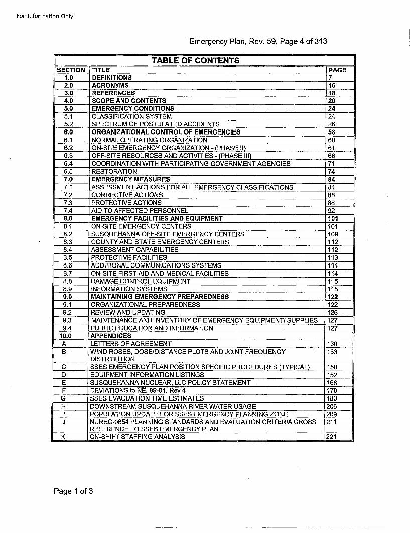
- ~~TABLE OF CONTENTS -PG
SECTION TITLE PG1.0 DEFINITIONS 72.0 ACRONYMS 163.0 REFERENCES 184.0 SCOPE AND CONTENTS 205.0 EMERGENCY CONDITIONS 245.1 CLASSIFICATION SYSTEM 245.2 SPECTRUM OF POSTULATED ACCIDENTS 266.0 ORGANIZATIONAL CONTROL OF EMERGENCIES 586.1 NORMAL OPERATING ORGANIZATION 606.2 ON-SITE EMERGENCY ORGANIZATION - (PHASE II) 616.3 OFF-SITE RESOURCES AND ACTIVITIES - (PHASE III) 666.4 COORDINATION WITH PARTICIPATING GOVERNMENT AGENCIES 716.5 RESTORATION 747.0 EMERGENCY MEASURES 847.1 ASSESSMENT ACTIONS FOR ALL EMERGENCY CLASSIFICATIONS 847.2 CORRECTIVE ACTIONS 6887.3 PROTECTIVE ACTIONS 887.4 AID TO AFFECTED PERSONNEL 928.0 EMERGENCY FACILITIES AND EQUIPMENT 1018.1 ON-SITE EMERGENCY CENTERS 1018.2 SUSQUEHANNA OFF-SITE EMERGENCY CENTERS 1098.3 COUNTY AND STATE EMERGENCY CENTERS 1128.4 ASSESSMENT CAPABILITIES 1128.5 PROTECTIVE FACILITIES 1138.6 ADDITIONAL COMMUNICATIONS SYSTEMS 1148.7 ON-SITE FIRST AID AND MEDICAL FACILITIES 1148.8 DAMAGE CONTROL EQUIPMENT 1158.9 INFORMATION SYSTEMS 1"159.0 MAINTAINING EMERGENCY PREPAREDNESS 1229.1 ORGANIZATIONAL PREPAREDNESS 1229.2 REVIEW AND UPDATING 1269.3 MAINTENANCE AND INVENTORY OF EMERGENCY EQUIPMENT! SUPPLIES 1279.4 PUBLIC EDUCATION AND INFORMATION 127
10.0 APPENDICESA LETTERS OF AGREEMENT 130B WIND ROSES, DOSE/DISTANCE PLOTS AND JOINT FREQUENCY 133
______DISTRIBUTION ___
C SSES EMERGENCY PLAN POSITION SPECIFIC PROCEDURES (TYPICAL) 150D EQUIPMENT INFORMATION LISTINGS 152E SUSQUEHANNA NUCLEAR, LLC POLICY STATEMENT 168F DEVIATIONS to NI-I 99-01, Rev 4 170G SSES EVACUATION TIME ESTIMATES 183H DOWNSTREAM SUSQUEHANNA RIVER WATER USAGE 206I POPULATION UPDATE FOR SSES EMERGENCY PLANNING ZONE 209
J NUREG-0654 PLANNING STANDARDS AND EVALUATION CRITERIA CROSS 211REFERENCE TO SSES EMERGENCY PLANI
K ON-SHIFT STAFFING ANALYSIS 1221
Page 1 of 3
For Information Only
EmergencyF T PLanEe.5,Pae5oS1
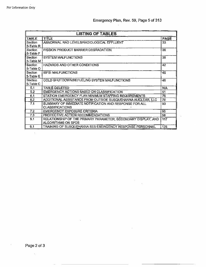
LISTING OF TABLESTABLE TITLE PAGESection IABNORMAL RAD LEVELS/RADIOLOGICAL EFFLUENT 335-Table RSection FISSION PRODUCT BARRIER DEGRADATION 365-Table FSection SYSTEM MALFUNCTIONS 395-Table MSSection HAZARDS AND OTHER CONDITIONS 425-Table 0O___Section ISESI MALFUNCTIONS 455-Table E____Section COLD SHUTDOWN/REFUELING SYSTEM MALFUNCTIONS 465-Table C____
5.1 TABLE DELETED N/A5.2 EMERGENCY ACTIONS BASED ON CLASSIFICATION 516.1 STATION EMERGENCY PLAN MINIMUM STAFFING REQUIREMENTS 766.2 ADDITIONAL ASSISTANCE FROM OUTSIDE SUSQUEHANNA NUCLEAR, LLC 787.1 SUMMARY OF IMMEDIATE NOTIFICATION AND RESPONSE FOR ALL 93
CLASSIFICATIONS7.2 EMERGENCY EXPOSURE CRITERIA 95•7.3 PROTECTIVE ACTION RECOMMENDATIONS 988.1 RELATIONSHIP OF THE PRIMARY PARAMETER, SECONDARY DISPLAY, AND 117
ALGORITHMS ON SPDS ___
9.1 TRAINING OF SUSQUEHANNA SES EMERGENCY RESPONSE PERSONNEL 128
Page 2 of 3
For Information Only
EmerN O FGUEncSln e.59 ae6o1
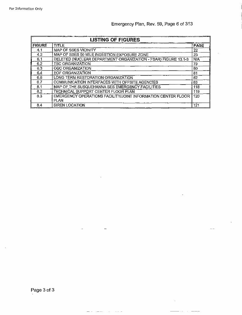
LISTING OF FIGURESFIGURE TITLE PAGE
4.1 MAP OF SSES VICINITY 224.2 MAP OF SSES 50 MILE INGESTION EXPOSURE ZONE 236.1 DELETED (NUCLEAR DEPARTMENT ORGANIZATION - FSAR) FIGURE 13.1-3 N/A6.2 TSC ORGANIZATION 796.3 OSC ORGANIZATION 806.4 EOF ORGANIZATION 816.6 LONG TERM RESTORATION ORGANIZATION 826.7 COMMUNICATION INTERFACES WITH OFFSITE AGENCIES 838.1 MAP OF THE SUSQUEHANNA SES EMERGENCY FACILITIES 1188.2 TECHNICAL SUPPORT CENTER FLOOR PLAN 1198.3 EMERGENCY OPERATIONS FACILITY/JOINT INFORMATION CENTER FLOOR 120_______PLAN
8.4 SIREN LOCATION 121
Page 3 of 3
For Information Only
Emergency Plan, Rev. 59, Page 7 of 313
[ ~1.0 DEFINITONs 1
1. ACCIDENT - an unforeseen and unintentional event which may result in an emergency.
2. ACTIVATE.- an emergency response facility has sufficient staffing to perform requiredfunctions and the facility has taken over command and control of the emergency. Thepositions required to activate the TSC, OSC and EOF are specified with an * in Figures6.2, 6.3 and 6.4. The terms "activated", "activation" "activation time" and "take overmanagement of the emergency" have the same definition.
3. AFFECTING SAFE SHUTDOWN - Event in progress has adversely affected functionsthat are necessary to bring the plant to and maintain it in the applicable HOT or COLDSHUTDOWN condition. Plant condition applicability is determined by TechnicalSpecification LCOs in effect.
Example 1: Event causes damage that result in entry into an LCO that requires theplant to be placed in HOT SHUTDOWN. HOT SHUTDOWN isachievable, but COLD SHUTDOWN is not. This event is not"AFFECTING SAFE SHUTDOWN."
Example 2: Event causes damage that result in entry into an LCO that requires theplant to be placed in COLD SHUTDOWN. HOT SHUTDOWN isachievable, but COLD SHUTDOWN is not. This event is "AFFECTINGSAFE SHUTDOWN."
4. ALERT - Events are in process or have occurred which involve an actual or potentialsubstantial degradation of the level of safety of the plant or a security event that involvesprobable life threatening risk to site personnel or damage to site equipment because ofHOSTILE ACTION. Any releases are expected to be limited to small fractions of the EPAProtective Action Guideline exposure levels.
5. ANNUAL - occurring within calendar year starting January 1 and ending December 31.
6. ALERT NOTIFICATION SYSTEM - sirens with ratings of 121 dB at 100' within theten-mile EPZ around the Susquehanna Steam Electric Station. Siren location wasdetermined by a detailed study including field surveys, actual determination of averagebackground noise level, and consideration of population distribution within the 10-mileEPZ.
7. ASSESSMENT ACTIONS - those actions taken during or after an incident to obtain andprocess information that is necessary to make decisions to implement specificemergency measures.
8. BIENNIAL EXERCISE - NRC/DHS-FEMA exercise performed on alternate years, to becompleted within the calendar year scheduled.
9. BIWEEKLY - occurring on alternate weeks, within the 7-day week.
10. BOMB - refers to an explosive device suspected of having sufficient force to damageplant systems or structures.
11. CDE - the Committed Dose Equivalent; dose to an organ due to an intake of radioactivematerial during the 50 year period following the intake.
Page 1 of 9
For Information Only
Emergency Plan, Rev. 59, Page 8 of 313
12. CIVIL DISTURBANCE - A CIVIL DISTURBANCE COULD BE FOREWARNED ORSPONTANEOUS. Information of a CIVIL DISTURBANCE could be expressed bytelephone, mail, hand delivered or other means. Plans of a CIVIL DISTURBANCE maybe given dilrectly or indirectly through a law enforcement agency, mass media,organization or some other party. A group of unexpected or unauthorized individuals isobserved outside the PROTECTED AREA or facility management is informed of plans tostage such a gathering (e.g. labor picket line, protest demonstrations, etc.)
13. COLUMBIA COUNTY EMERGENCY MANAGEMENT AGENCY (CCEMA) - emergencyresponse coordinating agency for Columbia County, responsible for implementingoff-site action upon direct notification from Susquehanna SES or PEMA.
14. CONFINEMENT BOUNDARY - is the barrier(s) between areas containing radioactivesubstances and the environment.
15. CONTAINMENT CLOSURE - is considered to be Secondary Containment as requiredby Technical Specifications.
16. CONTROL ROOM - the location of the Control Panels from which the reactor and itsauxiliary systems are controlled.
17. CORPORATE LEADERSHIP COUNCIL (CLC) - the Talen Management group whichdetermines major policy commitments for the company. The CLC membership includesthe President of the company and other senior executives.
18. CORRECTIVE ACTIONS - those emergency measures taken to ameliorate or terminatean emergency situation.
19. DEPARTMENT OF ENVIRONMENTAL PROTECTION/BUREAU OF RADIATIONPROTECTION (DEP/BRP) - the State agency responsible to provide guidance andrecommendations for specific off-site protective measures.
20. DEPARTMENT OF HOMELAND SECURITY - Federal Emergqency ManagqementAgqency (DHS-FEMA) - within the context of this plan, serves as the primary contact forrequests for Federal assistance; lead coordinator all non-technical federal response.
21. DOSE PROJECTION - a calculated estimate of the potential radiation dose toindividuals at a given location, normally off-site, (determined from the quantity ofradioactive material released and the appropriate meteorological transport anddispersion parameters).
22. DOSE RATE - the amount of radiation an individual can potentially receive per unit of time.
23. EFFECTIVE DOSE EQUIVALENT (EDE) - the sum of the products of the doseequivalent to the organ or tissue and the weighting factors applicable to each of the bodyorgans or tissues that are irradiated.
24. EMERGENCY ACTION LEVELS (EAL) - operational or radiological parameters which,when exceeded, require the implementation of portions of this plan. EALs for variousemergency conditions are specified in Section 5 Tables R, F, M, 0, E and C.
25. EMERGENCY ACTIONS - those steps taken, as a result of exceeding an EmergencyAction Level in the Emergency Plan, to ensure that the situation is assessed and that theproper corrective and/or protective actions are taken.
Page 2 of 9
For Information Only
Emergency Plan, Rev. 59, Page 9 of 313
26. EMERGENCY ALERT SYSTEM (EAS) - radio and television broadcast system used bypublic emergency management officials to notify the public concerning protective actions
•to be taken in the event of natural disasters, radiological protective actions, and otherinformation of immediate impact to the public. Formerly referred to as the Civil DefenseEmergency Broadcast System.
27. EMERGENCY CONDITION - the characterization of several classes of emergencysituations consisting of exclusive groupings including the entire spectrum of possibleradiological emergency situations. The four classes of emergencies, listed in increasingseverity, which Susquehanna has incorporated into this Emergency Plan, are outlined inSection 5.0 of this plan.
28. EMERGENCY COORDINATORS - designated Susquehanna SES staff membersresponsible for coordinating specific emergency organization functions.
29. EMERGENCY DIRECTOR (ED) - the Susquehanna individual responsible for directionof on-site activities during an emergency at the Susquehanna SES.
30. EMERGENCY OPERATIONS CENTERS - designated state and county emergencymanagement agency headquarters facilities designed and equipped for the purpose ofexercising effective coordination and control over disaster operations carried out withintheir jurisdiction.
31. EMERGENCY OPERATIONS FACILITY - Emergency Response Facility co-located with theJoint Information Center in Plains Township, Pennsylvania, to provide continuouscoordination and evaluation of Susquehanna activities during an emergency having orpotentially having environmental consequences (Reference REFERENCES, Section 3.19).
32. EMERGENCY PLAN BOUNDARY - same as the EXCLUSION AREA, i.e., that areaaround Susquehanna SES within a radius of 1800 feet determined in accordance with10 CFR 100.11. The dose criterion of 10 CFR 50.67 applies at the EXCLUSION AREAboundary.
33. EMERGENCY PLAN IMPLEMENTING PROCEDURES - specific procedures defining indetail the action to be taken in the event of an emergency condition. The EmergencyPlan Implementing Procedures will be separate from, but may incorporate and refer to,normal plant operating procedures and instructions, Emergency Plan Position SpecificProcedures and Emergency Plan Technical Procedures.
34. EMERGENCY PLAN TECHNICAL PROCEDURES - procedures describing how toperform processes associated with the Emergency Plan. These procedures may includeprocesses such as Emergency Classification or Protective Action. Used together withEmergency Plan Position Specific Procedures, these procedures are designed toimplement the Emergency Plan during a declared emergency.
35. EMERGENCY PLANNING ZONE - there are two Emergency Planning Zones. The firstis an area, approximately 10 miles in radius around the Susquehanna SES, for whichemergency planning consideration of the plume exposure pathway has been given inorder to ensure that prompt and effective actions can be taken to protect the public in theevent of an accident. The second is an area approximately 50 miles in radius aroundthe Susquehanna SES, for which emergency planning consideration of the ingestionexposure pathway has been given.
Page 3 of 9
For Information Only
Emergency Plan, Rev. 59, Page 10 of 313
36. EMERGENCY PLAN POSITION SPECIFIC PROCEDURES - procedu~es describinghow to perform tasks assigned to emergency positions. Each procedure includes anoverview of the position's tasks, detailed instructions, and relevant material. Usedtogether, these procedures are designed to implement the Emergency Plan during adeclared emergency.
37. EMERGENCY RESPONSE ORGANIZATION (ERO) - The SSES organization that isactivated when an emergency classification has been declared that meets one of thefour emergency classifications.
38. EXCLUSION AREA - is a circle of radius 1800 feet with the center at the commonrelease point on the Unit 1 and Unit 2 Reactor Buildings as determined in accordancewith 10 CFR100.1 1. The dose criterion of 10 CFR 50.67 applies at the EXCLUSIONAREA boundary.
39. EXPLOSION - An EXPLOSION is a rapid, violent, unconfined combustion, or acatastrophic failure of pressurized equipment that imparts energy of sufficient force topotentially damage permanent structures, systems, or components.
40. EXTORTION - is an attempt to cause an action at the station by threat of force.
41. FIRE. - is combustion characterized by heat and light. Sources of smoke such asslipping drive belts or overheated electrical equipment do not constitute FIRES.Observation of flame is preferred but is NOT required if large quantities of smoke andheat are observed.
42. FULLY FUNCTIONAL- all minimum required staff as defined in Table 6.1 and thepositions designated by dashed lines in Figures 6.2, 6.3 and 6.4 are present.
43. GENERAL EMERGENCY - Events are in process or have occurred which involve actualor imminent substantial core degradation or melting with potential for loss of containmentintegrity or HOSTILE ACTION that results in an actual loss of physical control of thefacility. Releases can be reasonably expected to exceed EPA Protective ActionGuideline exposure levels offsite for more than the immediate site area.
44. HOSTAGE - is a person(s) held as leverage against the station to ensure that demandswill be met by the station.
45. HOSTILE FORCE - one or more individuals who are engaged in a determined assault,overtly or by stealth and deception, equipped with suitable weapons capable of killing,maiming, or causing destruction.
46. HOSTILE ACTION- An act toward a Nuclear Power Plant or its personnel that includesthe use of violent force to destroy equipment, take hostages, and/or intimidate the plantto achieve an end. This includes attack by air, land, or water using weapons, explosives,projectiles, vehicles, or other devices used to deliver destructive force. Other acts thatsatisfy the overall intent may be included. HOSTILE ACTION should not be construed toinclude acts of civil disobedience or felonious acts that are not part of a concerted attackon the power plant. Non-terrorism based EALs should be used to address suchactivities, (e.g. violent acts between individuals in the owner controlled area).
47. IMMEDIATELY DANGEROUS TO LIFE AND HEALTH (IDLH) - A condition that eitherposes an immediate threat to life and health or an immediate threat of severe exposureto contaminants which are likely to have adverse delayed effects on health.
Page 4 of 9
For Information Only
Emergency Plan, Rev. 59, Page 11 of 313
48. INTRUSION I INTRUDER - is a person(s) present in a specified area withoutauthorization. Discovery of a BOMB in a specified area is indication of INTRUSION intothat area by a HOSTILE FORCE.
49. INITIATING CONDITION (IC) - one of a predetermined subset of nuclear power plantconditions where either the potential exists for a radiological emergency, or such anemergency has occurred.
50. ISESI - Independent Spent Fuel Storage Facility - A series of adjacent concrete structureslocated within the SSES Protected Area that contain spent fuel storage canisters.
51. JOINT INFORMATION CENTER - the designated location from which news releases,press conferences and other media interfacing can be provided.
52. LDE - Lens Dose Equivalent; the external exposure to the lens of the eye.
53. LOWER FLAMMABILITY LIMIT (LFL) -The minimum concentration of a combustiblesubstance that is capable of propagating a flame through a homogenous mixture of thecombustible and a gaseous oxidizer.
54. LUZERNE COUNTY EMERGENCY MANAGEMENT AGENCY (LCEMA) - the hostcounty emergency response coordinating agency, responsible for implementing off-siteaction upon either direct notification from the Susquehanna SES or from PEMA.
55. MONTHLY -occurring within the calendar month.
56. NORMAL PLANT OPERATIONS - activities at the plant site associated with routine testing,maintenance, or equipment operations, in accordance with normal operating oradministrative procedures. Entry into abnormal or emergency operating procedures, ordeviation from normal security or radiological controls posture, is a departure from NORMALPLANT OPERATIONS.
57. NOTIFICATION OF UNUSUAL EVENT - Events are in process or have occurred whichindicate a potential degradation of the level of safety of the plant or indicate a securitythreat to facility protection has been initiated. No releases of radioactive materialrequiring offsite response or monitoring are expected unless further degradation ofsafety systems occurs.
58. NUCLEAR REGULATORY COMMISSION (NRC) - within the context of this plan, theFederal agency responsible for verifying that appropriate emergency plans have beenimplemented and for conducting investigative activities associated with a radiologicalemergency.
59. OFF-SITE - any area outside the Emergency Plan Boundary surrounding theSusquehanna SES.
60. OFF-SITE RADIOLOGICAL INCIDENT - any radiation incident affecting areas beyondthe Emergency Plan boundary and posing a significant threat to public health and safety.
61. ON-SITE - the area within the PROTECTED AREA.
Page 5 of 9
For Information Only
Emergency Plan, Rev. 59, Page 12 of 313
62. OPERATIONAL SUPPORT CENTER (OSC) - the primary on-site assembly area foroperations support team personnel during the initial phase of an emergency. Theprimary OSC is not in the control structure but is located in an administrative building. Inthe event of a large radioactive release, the OSC may be relocated to the back-up OSCthat is located in the control structure.
63. OWNER CONTROLLED AREA - includes the area within the expanded securityperimeter, i.e. the areas that are bordered by the Vehicle Barrier System. The OWNERCONTROLLED AREA encompasses the Monitored OWNER CONTROLLED AREA(MOCA) as defined in Security Procedures.
64. PENNSYLVANIA EMERGENCY MANAGEMENT AGENCY (PEMA) - within the contextof this plan, the lead state-agency for radiological emergency planning, response andrecovery and for providing guidance to local government for development of radiologicalemergency plans and programs.
65. PLANT PROCEDURES - those procedures utilized by the plant operations staff to controland manipulate the plant under both normal and abnormal circumstances.
66. PROTECTED AREA - An area encompassed by Physical Barriers and to which access iscontrolled.
67. PROTECTIVE ACTION GUIDES (PAG) - the projected dose to reference personnel, orother defined individual, from an unplanned release of radioactive material at which aspecific protective action to reduce or avoid that dose is recommended.
68. PROTECTIVE ACTIONS - those emergency measures taken for the purpose ofpreventing or minimizing radiological exposures.
69. QUARTERLY - occurring during the calendar quarter.
70. RADIATION DOSE - the quantity of radiation absorbed by the body or any portion of thebody.
71. RADIATION MONITORING SYSTEM - an in-plant system consisting of ARMs, CAMs,and process monitors that contributes to personal protection, equipment monitoring, andaccident assessment by measuring and recording radiation levels and concentrations atselected locations throughout the station. Reference Appendix D.
72. RADIOACTIVE MATERIAL - any solid, liquid, or gas which emits radiationspontaneously.
73. RADIOLOGICAL EMERGENCY RESPONSE TEAM - the response team from the Divisionof Radiological Health, State Board of Health, Pennsylvania Emergency ManagementAgency, and other State agencies, which will be dispatched to the scene of radiologicalemergencies. The team provides technical guidance and other services to localgovernments or an affected nuclear facility.
Page 6 of 9
For Information Only
Emergency Plan, Rev. 59, Page 13 of 313
74. RADIOLOGICALLY CONTROLLED AREA (RCA) - any temporary or permanent areaestablished by Health Physics, which is controlled for purposes of protection fromexposure to radiation or radioactive materials. Typically, the Radiologically ControlledArea is defined by the outer perimeters of the Turbine, Reactor, and RadwasteBuildings, portions of the Control Structure, and portions of LLRWHF.
75. RADIOLOGICALLY CONTROLLED AREA EVACUATION - evacuation of nonessentialindividuals from some or all of the Radiologically Controlled Area.
76. RECOVERY ACTIONS - those actions taken after the emergency to restore the plant asnearly as possible to its pre-emergency condition.
77. RECOVERY MANAGER - the individual responsible for the management of emergencyresponse activities in the EOF during an emergency at the Susquehanna Steam ElectricStation.
78. REM. (Acronym for roentgen equivalent man) - a unit of measure of radiation dose inbiological tissue.
79. REMOTE ASSEMBLY AREA - a designated area, outside the exclusion area, for theassembly of evacuated plant personnel, if necessary, during a Site Evacuation. ThePrimary Remote Assembly Area is the Susquehanna Energy Information Center. Thealternate assembly area is the West Building.
80. REMOTE MONITORING SYSTEM - fixed radiation detectors located near the siteperimeter and mobile monitoring equipment to locate and assess elevated radiation levels.
81. ROUTE ALERTING TEAMS - a back-up to the siren system that is implemented, asnecessary, in the event of siren failure or to alert persons or areas that may not be withinthe sound of the sirens. Route alerting is a municipal responsibility and is accomplishedby municipal route alert teams traveling in vehicles along preplanned routes deliveringthe following message: "There is an emergency at the Susquehanna Steam ElectricStation; please tune to your Emergency Alert Station."
82. SDE - Shallow Dose Equivalent; external exposure of the skin or extremity which ismeasured at 0.007 cm in tissue.
83. .S.ABOTAGE - is deliberate damage, mis-alignment, or mis-operation of plant equipmentwith the intent to render the equipment inoperable. Equipment found tampered with ordamaged due to malicious mischief may NOT meet the definition of SABOTAGE untilthis determination is made by security supervision.
84. SAFE SHUTDOWN SYSTEMS/EQUIPMENT - consists of the following: DieselGenerators, HPCI, Core Spray, Standby Gas Treatment System, RCIC, 4kV SafeguardBuses, ESW, ADS, RHR, RHRSW, Remote Shutdown Panels and DC Vital Buses.
85. SECURITY CONDITION - Any Security Event as listed in the approved securitycontingency plan that constitutes a threat/compromise to site security, threat/risk to sitepersonnel, or a potential degradation to the level of safety of the plant. A SECURITYCON DITION does not involve a HOSTILE ACTION.
Page 7 of 9
For Information Only
Emergency Plan, Rev. 59, Page 14 of 313
86. SHIFT MANAGER - the individual who acts in the capacity of Susquehanna SteamElectric Station emergency manager immediately upon concurrence of an emergency asdescribed in the SSES Emergency Plan. The designation Shift Manager is synonymouswith the designation Shift Supervisor and may be used interchangeably in theemergency plan. Both terms designate the same individual.
87. SIGNIFICANT TRANSIENT - is an UNPLANNED event involving one or more of thefollowing: (1) Reactor Re-circulation System runback involving a power reduction of over25% thermal reactor power, (2) electrical load rejection >25% full electrical load, (3)Reactor Trip, (4) ECCS Actuations, or (5) thermal power oscillations >10%.
88. SITE AREA EMERGENCY - Events are in process or have occurred which involveactual or likely major failures of plant functions needed for protection of the public orHOSTILE ACTION that results in intentional damage or malicious acts; (1) toward sitepersonnel or equipment that could lead to the likely failure of or; (2) that prevent effectiveaccess to equipment needed for the protection of the public. Any releases are notexpected to result in exposure levels that exceed EPA Protective Action Guidelineexposure levels beyond the site boundary.
89. SITE BOUNDARY - that line, beyond which the land is not owned, leased or otherwisecontrolled by the licensee. (Susquehanna drawing C243786, Sh 1, "Site Facilities andBoundary Map.")
90. SITE EVACUATION - evacuation of all non-essential personnel from the Exclusion Area.
91. STATE - the Commonwealth of Pennsylvania.
92. STATION ACCOUNTABILITY AREAS - areas designated for the gathering of individualsfor the purpose of personnel accountability. Typically these are large areas withinstalled card readers to facilitate electronic accounting for personnel. Specific locationsare defined in station procedures.
93. STRIKE ACTION - is a work stoppage within the PROTECTED AREA by a body ofworkers to enforce compliance with demands made on SSES. The STRIKE ACTIONmust threaten to interrupt NORMAL PLANT OPERATIONS.
94. SUSQUEHANNA NUCLEAR, LLC - subsidiary company of Talen Energy Corporationthat owns and operates Susquehanna Steam Electric Station. The Emergency Plan willrefer to this company as Susquehanna.
95. SUSTAINED HIGH WINDS - winds whose speed exceeds the specified value for greaterthan 1 minute. Wind gusts of shorter duration do not meet this criterion. SSES FSARSection 3.3 'W'ind and Tornado Loadings specifies the 80mph design limit for SSESstructures. FSAR Section 3.3.1.1 "Design Wind Velocity" references ASCE document:"Wind Forces on Structures," ASCE paper No. 3269, Transaction Volume 126, Part II(1961), Pg. 1124. The ASCE paper provides guidance for the use of the term sustainedwhen dealing with wind loadings of structures.
Page 8 of 9
For Information Only
Emergency Plan, Rev. 59, Page 15 of 313
96. TECHNICAL SUPPORT CENTER - a designated on-site location where the conditionsduring and after an accident can be analyzed to provide technical and radiologicalassessments of the accident to the Emergency Director. In the event of certain hazardspreventing site access or certain security related events, personnel who normally report tothe Technical Support Center may report to the Emergency Operations Facility wherearrangements will be made to accommodate TSC-specific functions not assumed by theEOE. The alternate TSC will be activated as soon as possible to support the site; however,it is recognized that the activation time for the alternate TSC may exceed 60 minutes."
97. TEDE. - Total Effective Dose Equivalent; integrated doses consisting of the sum ofexternal doses from plume shine, 50 year committed effective dose equivalent frominhalation (CEDE), and 4 day ground shine doses.
98. THYROID DOSE - radiation exposure to the thyroid resulting from an intake ofradioactive materials.
99. TRANSMISSION POWER DISPATCHER - individual manning the transmission anddistribution system for PPL Corporation.
100. UNPLANNED - a parameter change or an event that is not the result of an intendedevolution and requires corrective or mitigate action.
101. VALID - an indication, report, or condition is considered to be VALID when it is verified by(1) an instrument channel check, or (2) indications on related redundant indicators, or (3) bydirect observation by plant personnel, such that doubt related to the indicator's operability,the condition's existence, or the report's accuracy is removed. Implicit in this definition is theneed for timely assessment.
102. VISIBLE DAMAGE - is damage to equipment or structure that is readily observablewithout measurements, testing, or analysis. Damage is sufficient to cause concernregarding the continued operability or reliability of affected safety structure, system, orcomponent. Example damage includes: deformation due to heat or impact, denting,penetration, rupture, cracking, paint blistering. Surface blemishes (e.g., paint chipping,scratches) should not be included.
103. VITAL AREAS - is any area, normally within the PROTECTED AREA, which containsequipment, systems, components, or material, the failure, destruction, or release ofwhich could directly or indirectly endanger the public health and safety by exposure toradiation. Plant VITAL AREAS include the following: SCC, Control Structure, DieselGenerator Buildings, ESSW Pump House, Spray Pond and Reactor Buildings.
104. WHOLE BODY EXPOSURE - direct radiation exposure to the body from externalsources.
Letter dated February 25, 2002 from Samuel J. Collins, Director, Office of Nuclear Reactor Regulations,to Robert G. Byram, Senior Vice President and Chief Nuclear Officer. Subject: Issuance of Order forInterim Safeguards and Security Compensatory Measures for - Susquehanna Steam Electric Station,Units 1 & 2.Page 9 of 9
For Information Only
Eme A RgeNcYMPaRvS9 Pg 6o1
2.0 ACRONYMS
2.12.22.32.42.52.62.72.82.92.102.112.122.132.142.15
2.162.172.182.192.202.212.222.232.242.252.262.272.282.292.302.312.322.332.342.352.362.372.382.392.402.412.422.432.442.45
Page 1
ANS -ARI.-ARM -ASCC -CAM -CCEMA -CEDE -
CR-CREOASS -
CSARCTN -DAC -DCS -DEP/BRP -
DHS -FEMA
DOE -EAL -EAS -EGGS -
ED-EDE -EMA -EMCO-EOC -EOF -EP -
EPA -EP-PS -
EPZ -ERDS -
ERF-.EROETN -FPCO-FRC -FRERP -
FRMAC -
FSAR -
FTS -HHS -HPCI -
JICG-LCEMA -LCO -LER -
of 2
Alert Notification SystemAlternate Rod InsertionArea Radiation MonitorsAlternate Security Control CenterContinuous Air MonitorsColumbia County Emergency Management AgencyCommitted Effective Dose EquivalentControl RoomControl Room Emergency Outside Air Supply SystemCertified Safety Analysis ReportCentrex Telephone NetworkDerived Air ConcentrationDocument Control ServicesDepartment of Environmental Protection/Bureau of Radiological ProtectionDepartment of Homeland Security - Federal Emergency ManagementAgencyU.S. Department of EnergyEmergency Action LevelsEmergency Alert SystemEmergency Core Cooling SystemsEmergency Director at Susquehanna SESEffective Dose EquivalentEmergency Management AgencyEmergency Management Coordinator (Municipality)Emergency Operations CenterEmergency Operations FacilityEmergency PreparednessEnvironmental Protection AgencyEmergency Plan Position Specific ProceduresEmergency Planning ZoneEmergency Response Data SystemEmergency Response FacilityEmergency Response Organization for SSESElectronic Tandem NetworkFuel Pool CoolingFederal Response CoordinatorFederal Radiological Emergency Response PlanFederal Radiological Monitoring and Assessment CenterSusquehanna SES Final Safety Analysis Report, Units 1 and 2Federal Telecommunications SystemHealth and Human ServicesHigh Pressure Coolant Injection SystemJoint Information CenterLuzerne County Emergency Management AgencyLimiting Condition for OperationLicense Event Report
For Information Only
Emergency Plan, Rev. 59, Page 17 of 313
2.462.472.482.492.502.512.522.532.542.552.562.572.582.592.602.612.62
2.632.642.652.662.672.682.692.702.712.722.732.742.752.762.772.782.792.802.81
2.822.832.84
2.852.862.872.882.892.90
LLRWHF -LOCA -MOCA -MIDAS -
MSIV.-MSL -NEP -NRC -NRP -NSRBNSSS -
ODCM -OSC -PAGS -
PASS -
PEMA -PlCSY -
PORC -PPL -PSP -
RCA -RClC -RDAS -
RHR -RPS -RMSRx-SCC -SDE -SDS -SEIC -SGTS -
SLC -SOCA -SPDS -
SPINGs -
SSE -SSESSusquehanna
TEDE -TR-TSC -UMCO-UPS -USDA -
Low Level Radwaste Holding FacilityLoss of Coolant AccidentMonitored Owner Controlled AreaMeteorological Information and Dose Assessment SystemMain Steam isolation ValveMain Steam LineNuclear Emergency PlanningNuclear Regulatory CommissionNational Response PlanNuclear Safety Review BoardNuclear Steam Supply SystemOffsite Dose Calculation ManualOperations Support CenterProtective Action Guides from EPAPost Accident Sampling SystemPennsylvania Emergency Management AgencyPlant Integrated Computer System, synonymous with Plant ProcessComputer (PPC) or R*TIMEPlant Operations Review CommitteePPL CorporationPennsylvania State PoliceRadiologically Controlled AreaReactor Core isolation CoolingRemote Data Analysis SystemResidual Heat RemovalReactor Protection SystemRemote Monitoring SystemReactorSecurity Control CenterShallow Dose EquivalentSatellite Display SystemSusquehanna Energy Information CenterStandby Gas Treatment SystemStandby Liquid ControlSecurity Owner Controlled AreaSafety Parameter Display SystemSystem Particulate, Iodine, and Noble Gas Monitor (Vent MonitoringSystem)Safe Shutdown EarthquakeSusquehanna Steam Electric StationSusquehanna Nuclear, LLC (subsidiary company of Talen EnergyCorporation)Total Effective Dose EquivalentTemperature RecorderTechnical Support CenterUnit Monitoring Console (PCS)Uninterruptible Power SupplyUnited States Department of Agriculture
Page 2 of 2
For Information Only
Emergency Plan, Rev. 59, Page 18 of 313
3.0 REFERENCES
3.1 Columbia County Radiological Emergency Response Plan to Nuclear Power PlantIncidents.
3.2 DEP/BRP Emergency Plan - Bureau of Radiation Protection "Plan for Nuclear PowerGenerating Station Incidents".
3.3 NRC Generic Letter 91-14, "Emergency Telecommunications".
3.4 Luzerne County Radiological Emergency Response Plan to Nuclear Power Plant
Incidents.
3.5 NUREG 0654/FEMA-REP-1 - Criteria for Preparation and Evaluation of RadiologicalEmergency Response Plans and Preparedness In Support of Nuclear Power Plants.
3.6 NUREG 0696 - Final Report - Functional Criteria for Emergency Response Facilities.
3.7 NUREG 0737 - Clarification of TMI Action Plan Requirements.
3.8 NUREG 1392 - Emergency Response Data System Implementation.
3.9 PEMA Emergency Plan - Annex E to Commonwealth of Pennsylvania "DisasterOperations Plan", Nuclear Incidents (Fixed Facility).
3.10 Susquehanna SES Emergency Plan Position Specific Procedures.
3.11 Susquehanna SES Letters of Agreement with off-site emergency organizations(Appendix A).
3.12 Susquehanna Nuclear, LLC Security Plan.
3.13 Susquehanna SES Plant Procedures.
3.14 I0CFR Part 50 - Domestic Licensing of Production and Utilization Facilities.
3.15 Design of the Siren Alerting System for the Susquehanna Steam Electric Station: FinalReport.
3.16 SSES Preparedness, Prevention and Contingency Plan.
3.17 EPA 400-R-91-001 - Manual of Protective Action Guides and Protective Actions forNuclear Incidents.
3.18 NEI 99-01 Revision 4, "Methodology for Development of Emergency Action Levels".
3.19 NRC Letter dated April 17, 1996, MOVING THE EOF TO THE NORTHEAST DIVISIONHEADQUARTERS (TAC NOS. M91377 AND M91 378), Docket Nos. 50-387/50-412.
Page 1 of 2
For Information Only
Emergency Plan, Rev. 59, Page 19 of 313
3.20 Letter dated February 25, 2002 from Samuel J. Collins, Director, Office of NuclearReactor Regulations, to Robert G. Byram, Senior Vice President and Chief NuclearOfficer. Subject: Issuance of Order for Interim Safeguards and Security CompensatoryMeasures for - Susquehanna Steam Electric Station, Units 1 & 2.
3.21 Susquehanna Nuclear, LLC Training and Qualification Plan.
3.22 Regulatory Guide 1.101 Emergency Planning and Preparedness for Nuclear PowerReactors (Revision 3, August 1992).
3.23 NRC Bulletin 2005-02 Emergency Preparedness and Response Actions for SecurityBased Events July 18, 2005.
3.24 Regulatory Issue Summary 2004-15, Supplement 1, Emergency Preparedness Issues:Post-9/1 1.
3.25 EC 690275/AR 850156, Extended Power Uprate (EPU) Impact Evaluation.
3.26 NE! 03-12, Template for Security Plan and Training and Qualification Plan, June 2004.
Page 2 of 2
For Information Only
Emergency Plan, Rev. 59, Page 20 of 313
I ~4.0 SCOPE AND CONTENTS I
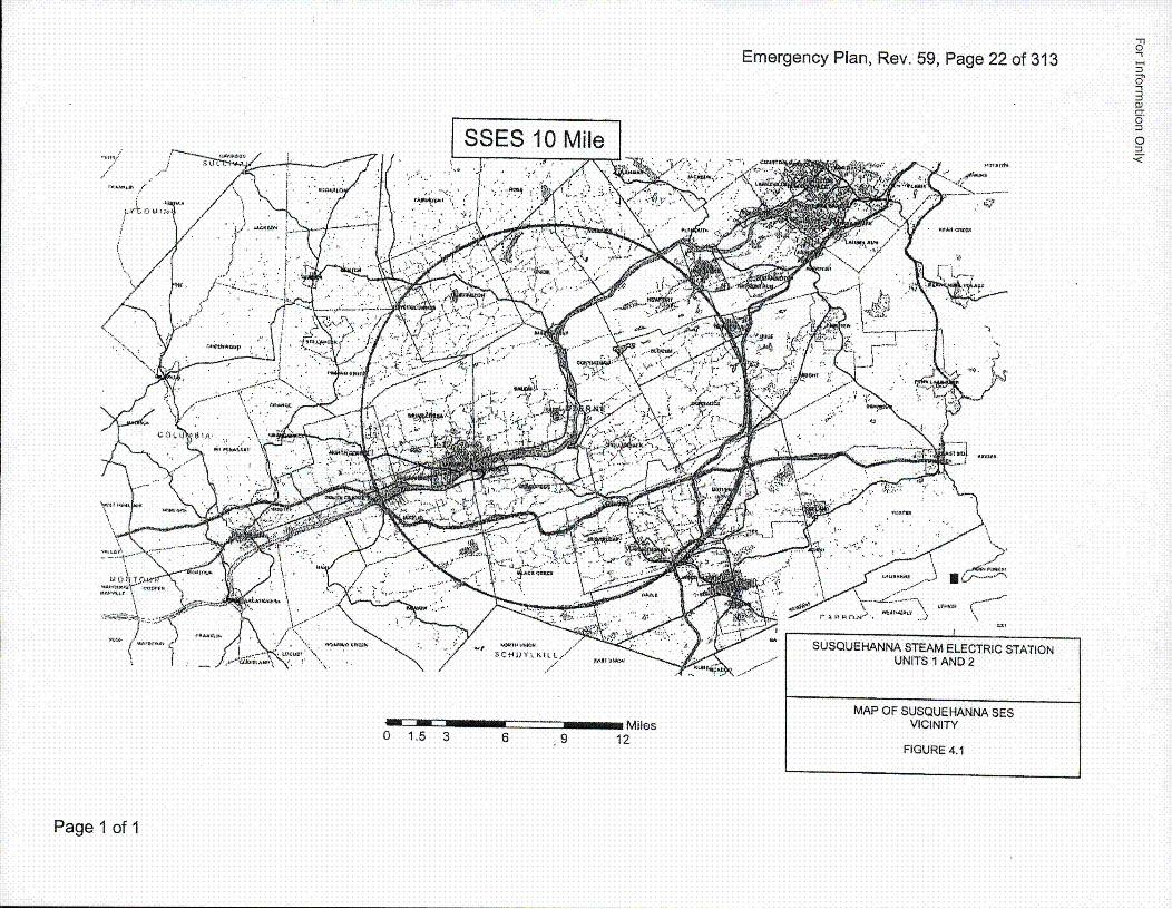
SSES includes two boiling water reactor electrical generating units. The station is located in SalemTownship, Luzerne County, in east central Pennsylvania; about five miles northeast of Berwick,Pennsylvania (see Figure 4.1). This Emergency Plan applies to the operation of Unit 1 and Unit 2.
4.1 SCOPE
This Plan provides guidance for both on-site and off-site emergency situations, It ranges inscope from relatively minor events and occurrences involving small releases of radioactivematerial, up to and including a major nuclear emergency having significant off-siteradiological consequences. This Plan, together with the state, county, and municipalradiological emergency response plans, provides detailed guidance and direction for takingemergency measures by the ERO to ensure the health and safety of the public living withinthe 10-mile EPZ of SSES. Additional guidance is provided in state and county plans foringestion pathway preventive measures out to 50 miles (see Figure 4.2).
Additional guidance on specific emergency actions for non-radiological releases ofhazardous materials can be found in the SSES Preparedness, Prevention, andContingency Plan.
4.2 CONTENTS
4.2.1 Classification
This Plan provides for a graded response for distinct classifications ofemergency conditions, action within those classifications, and criteria forescalation to another classification. This classification system is alsoused by PEMA, DEP/BRP, LCEMA, and CCEMA. This system is coveredin Section 5.0.
4.2.2 Organization Control
The Susquehanna organization for control of emergencies begins with theon-shift station personnel and contains provisions for augmentation andextension to include other station personnel, Talen corporate personnel,and outside emergency response organizations.
The total emergency program includes the support of state, federal and localemergency organization~s. Detailed provisions are made for implementingprotective measures against direct radiation exposure for the public within aradius of at least ten miles from the SSES. Additional preventive measuresmay be taken beyond that distance to preclude ingestion pathway exposures.
Specific agreements are also made with local off-site support organizations toprovide firefighting, medical, law enforcement, and traffic control services.
State, County, and Federal agencies have lead responsibilitiesspecifically related to this Plan.
Organizational control is covered in Section 6.0.Page 1 of 2
For Information Only
Emergency Plan, Rev. 59, Page 21 of 313
4.2.3 Emergqency Measures
The mechanisms through which this Plan provides for the proper responseto emergency conditions at SSES include identification of the event, initialand ongoing assessment, and initial and ongoing emergency actions.Emergency actions include classification of event, completion ofnotifications, activation of onsite and offsite ERO, requests for offsiteassistance, implementing onsite protective actions, recommending offsiteprotective actions, and activation of the restoration organization. Thesemechanisms are discussed in Section 7.0.
4.2.4 Emergqency Facilities
Emergency facilities and equipment are provided to ensure thecapabilities for prompt, efficient assessment and control of situations overthe entire spectrum of probable and postulated emergency conditions.The facilities and associated equipment and their emergency functionsare described in Section 8.0.
4.2.5 Emergqency Trainingq
A concept of in-depth preparedness is employed regarding the SSESemergency preparedness program. This concept is emphasized in thetraining program and in preparedness drills and exercises. Personnel aretrained to provide an in-depth response capability for required actions inan emergency situation. Section 9.0 includes the means to achieve andmaintain preparedness and to ensure maintenance of an effectiveemergency program.
Page 2 of 2
Emergency Plan, Rev. 59, Page 22 of 313
S// Ji ." "'2.• - " .
• i , ,. ... .'•", '. - .D •.,- ..• , ,--* . .
I 4*LtE •t kI SUQUHAN S ,TEAM ELCTICTTO
/ .. .: .. . .. .- ., , , . .. . M AP.• O F " U U,< , N A S EMiesVIINT
O 1,.5.. 3-••' 6 • 9. 12 FIGU E4.
0r
0
DJ0'='
Page 1 of 1
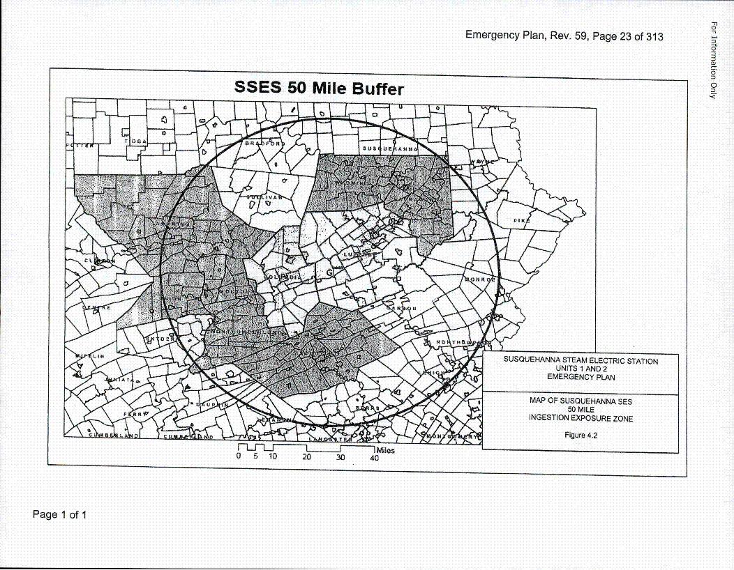
Emergency Plan, Rev. 59, Page 23 of 313'1
0o1
0<
Page 1 of I
For Information Only
Emergency Plan, Rev. 59, Page 24 of 313
5.0 EMERGENCY CONDITIONS I5.1 CLASSIFICATION SYSTEM
Emergency conditions are grouped into four classifications that cover the entirespectrum of probable and postulated accidents. These classifications are Notification ofUnusual Event, Alert, Site Area Emergency, and General Emergency. Action levelcriteria are specified for determining and declaring each emergency classification.Planning is coordinated with State and county agencies to ensure that this classificationsystem is compatible with the system used by those agencies. The system provides fornotification of appropriate emergency response organizations and for implementation ofactions immediately applicable to a specific condition. Provisions are included forupgrading the classification level and the corresponding response in the event of achange in the emergency condition.
Recognition and action level criteria are based on readily available information such asControl Room instrumentation. Immediate actions for response to conditions involvingplant operating parameters, such as Technical Specification Limiting Conditions forOperation (LCOs), are detailed in the Plant Procedures.
The emergency classification system, initiating conditions, and EAL thresholds for eachinitiating condition are defined in Tables R, F, M, 0, E and C. This table demonstrateshow an initiating condition leads directly to the appropriate emergency classificationbased on the magnitude of the event. In many cases, the proper classification isimmediately apparent from in-plant instrumentation. In other cases, more extensiveassessment is necessary to determine the applicable emergency classification.Continuing reassessment is required to ensure that the classification is consistent withthe conditions. The emergency actions that will be taken for each of the four emergencyclassifications are shown in Table 5.2.
5.1.1 Notification of Unusual Event
Events are in process or have occurred which indicate a potentialdegradation of the level of safety of the plant or indicate a security threatto facility protection has been initiated. No releases of radioactive materialrequiring offsite response or monitoring are expected unless furtherdegradation of safety systems occurs.
Conditions that constitute a Notification of Unusual Event classificationare outlined in Tables R, F, M, 0, E and C.
The ED declares a Notification of Unusual Event within 15 minutes ofhaving information-necessary to make a declaration.
Page 1 of 9
For Information Only
Emergency Plan, Rev. 59, Page 25 of 313
The emergency actions that will be taken by Susquehanna and offsiteagencies for an unusual event are listed in Table 5.2. In general the tablestates that the plant emergency management personnel and offsiteagencies will be notified by plant staff if a Notification of Unusual Event isdeclared. Plant staff will request assistance as necessary to disseminateinformation, make critical decisions and resolve the unusual event.
5.1.2 Alert
Events are in process or have occurred which involve an actual orpotential substantial degradation of the level of safety of the plant or asecurity event that involves probable life threatening risk to site personnelor damage to site equipment because of intentional malicious dedicatedefforts of HOSTILE ACTION. Any releases are expected to be limited tosmall fractions of the EPA Protective Action Guideline exposure levels.
Conditions that constitute an Alert classification are outlined in Tables R,F, M, 0 and C.
The ED or Recovery Manager declares an Alert within 15 minutes ofhaving information necessary to make a declar'ation.
The emergency actions that will be taken by Susquehanna and offsiteagencies for an Alert are listed in Table 5.2. In general the actions will besimilar to a Notification of Unusual Event but will also include the dispatchof monitoring teams if a radioactive release is involved.
5.1.3 Site Area Emergency
Events are in process or have occurred which involve actual or likelymajor failures of plant functions needed for protection of the public orHOSTILE ACTION that results in intentional damage or malicious acts;(1) toward site personnel or equipment that could lead to the likely failureof or; (2) that prevent effective access to equipment needed for theprotection of the public. Any releases are not expected to result inexposure levels that exceed EPA Protective Action Guideline exposurelevels beyond the site boundary.
Conditions that constitute a Site Area Emergency are outlined in TablesR, F, M, 0 and C.
The ED or Recovery Manager declares a Site Area Emergency within 15minutes of having information necessary to make a declaration.
The emergency actions taken by Susquehanna and offsite agencies for aSite Area Emergency are listed in Table 5.2. In general, the actions willbe similar to the actions taken for an Alert with increased emphasis oninformation dissemination, more senior technical and management staff inthe emergency response facilities, and additional field radiologicalmonitoring.
Page 2 of 9
For Information Only
Emergency Plan, Rev. 59, Page 26 of 313
5.1.4 General Emergqency
Events are in process or have occurred which involve actual or imminentsubstantial core degradation or melting with potential for loss ofcontainment integrity or HOSTILE ACTION that results in an actual lossof physical control of the facility. Releases can be reasonably expected toexceed EPA Protective Action Guideline exposure levels offsite for morethan the immediate site area.
Total activation of the onsite and offsite emergency organizations is requiredfor such events. Actions involving offsite populations are probable. Conditionsthat constitute a General Emergency are outlines in Tables R, F, M, 0 and C.
The ED or Recovery Manager declares a General Emergency within 15minutes of having information necessary to make a declaration.
The emergencyactions taken by Susquehanna and offsite agencies for aGeneral Emergency are listed in Table 5.2. In general the actions will besimilar to the actions taken for a Site Area Emergency with additionalresources dedicated to the health and safety of the general public.Additional actions include the initiation of predetermined protective actionsfor the public.
5.2 SPECTRUM OF" POSTULATED ACCIDENTS
The classification and corresponding protective actions relative to significant emergencyconditions are based primarily on the resultant or potential radiation doses. Methods aredescribed in this Plan and in EP Procedures for measuring, projecting and evaluatingthose doses.
The discrete accidents addressed in this section are those which are defined in theSSES FSAR as "design basis accidents" resulting in off-site dose consequences andaccidents involving the spent fuel storage facility (ISFSI). The following discussion ofthese postulated accidents and Tables R, F, M, 0, E and C identify the instrumentationand other mechanisms for prompt detection and continued assessment, anddemonstrates how each accident is encompassed within the emergency classificationsystem of this Plan. When an event also involves elevated off-site radiologicalconsequences or other specific conditions, the event classification will be adjusted toreflect actual conditions.
5.2.1 Control Rod Drop Accident
This accident is described in FSAR Section 15.4.9 and is postulated tooccur with the reactor in hot startup condition, and very conservativecalculations indicate failure of fuel rods. The main steam line radiationmonitors detect the significant increase in activity and initiate an alarm toalert operations personnel. Operations personnel would then validate thealarm condition, manually SCRAM the reactor and initiate closure of themain steam isolation valves (MSIV) and isolation of the main condenser.During the MSIV closing time period, noble gases and radioiodines aretransported with the steam to the condenser. Release of radioactivity tothe environment is by way of leakage from the turbine building.
Page 3 of 9
For Information Only
Emergency Plan, Rev. 59, Page 27 of 313
Initial assessment of this accident, performed by the Control RoomPersonnel under the direction of the ED includes evaluation of radiationlevels. Data are direct radiation levels at the locations of various turbinebuilding ARMs, and an indication of the airborne radioactivity concentrationfrom the turbine building vent exhaust monitor. EP-Procedures provideguidance for dose projections based on radiation readings. Data from theTurbine Building vent exhaust monitors is supplemented by informationobtained by the radiological monitoring team.
The emergency actions include:
a) Evaluate Emergency Action Levels per Tables R, F, M, 0 and C
b) Declare the appropriate classification as warranted
c) Implement Radiologically Controlled Area Evacuation
5.2.2 Fuel Handlingq
This accident is described in FSAR Section 15.7.4 and is postulatedto occur with the reactor in shutdown condition with the vessel headremoved and results in fuel failure. The reactor building ventilationexhaust duct radiation monitoring system alarms, isolates the ventilationsystem, and starts operation of the Standby Gas Treatment System(SGTS). Noble gases and radioiodines are released to the fuel pool,migrate to the secondary containment, and are released to theenvironment after filtration through the SGTS.
Initial assessment of this accident includes the performance of doseprojections in accordance with EP-PSs. Dose projections utilize datafrom the reactor building vent monitor, standby gas treatment ventmonitor, and meteorological instrumentation.
The emergency actions include:
a) Evaluate Emergency Action Levels per Tables R, F, M, 0 and C
b) Declare the appropriate classification as warranted
c) Implement Radiologically Controlled Area Evacuation
5.2.3 Main Steam Line Break
This accident is described in FSAR Section 15.6.4 and is postulated tooccur with the reactor in operating status. The steam line break occursoutside the containment and releases steam until complete closure of theMSIVs. Noble gases and radioiodines in the coolant are assumed to bereleased directly to the environment.
Page 4 of 9
For Information Only
Emergency Plan, Rev. 59, Page 28 of 313
The initial assessment of this event includes the performance of doseprojections. An estimate of the resultant doses can be made andcompared to those shown in Table 15.6-9 of the FSAR for worst caseconditions. Actual doses are proportional to the fission product activity inthe steam, as monitored by the off-gas release rate, prior to the accident.The doses in Table 15.6-9 of the ESAR are based on the assumption thatthe off-gas release rate is at the upper limiting condition for operation.Actual dose estimates, and corresponding emergency actions, may betaken, based on the off-gas release rate prior to the accident.Consideration may also be given to the relative benefit from taking or nottaking specific protective action, based on the short-term duration ofexposure associated with this accident.
The emergency actions include:
a) Evaluate Emergency Action Levels per Tables R, F, M, 0 and C
b) Declare the appropriate classification as warranted
c) Implement Radiologically Controlled Area Evacuation
5,2.4 Instrument Line Break
This accident is described in the FSAR section 15.6.2 and is acircumferential rupture of an instrument line connected to the primarycoolant system postulated to occur outside the primary containment butinside the secondary containment. This failure results in the release ofprimary system coolant to the secondary containment, until the reactor isdepressurized. Operator recognition of the accident is by a combinationof alarms or abnormal readings or by comparison of radiation,temperature, humidity, fluid and noise readings with several instrumentsmonitoring the same process variable such as reactor level, jet pumpflow, steam flow, and steam pressure.
Design Basis analysis shows that the event analyzed in Subsection15.6.5 is bounding. The following describes a realistic analysis of theevent. The iodine concentration prior to the break is assumed to be 0.2micro-curies/gram dose equivalent 1-131, which is the maximumequilibrium concentration for continued full-power operation permitted bythe Technical Specifications. All of the iodine activity in the steam fromthe flashed liquid and steam from the steam dome and 10 percent fromthe remaining liquid released from the break are assumed to becomeairborne. A plateout factor of 2 is assumed for airborne iodine insidesecondary containment. Although there will be some activation andcorrosion products released the isotopes of primary importance are theiodine isotopes.
The emergency actions include:
a) Evaluate Emergency Action Levels per Tables R, F, M, 0 and C
Page 5 of 9
For Information Only
Emergency Plan, Rev. 59, Page 29 of 313
b) Declare the appropriate classification as warranted
c) Implement Radiologically Controlled Area Evacuation
5.2.5 Loss of Coolant Accident (LOCA)
This accident is described in FSAR Section 15.6.5 and is postulated toinvolve a complete circumferential break of a recirculating loop pipe insidethe primary containment, with the reactor operating at full power. Theaccident results in release of a significant quantity of fission products intothe primary containment, leakage into the secondary containment, andrelease to the environment through the SGTS. Containment failure,although not likely, must be considered possible.
The occurrence of a design basis LOCA is uniquely identified by low-lowreactor water level and high drywell pressure signals from the reactorprotection system sensors and high radiation signal from the containmentaccident radiation monitor(s). A reactor scram and MSIV closure occur.Operation of the emergency core cooling system is initiated.
The radiological exposures resulting from the activity released to theenvironment as a consequence of the LOCA have been determined forthe realistic and design basis cases. The design basis and realisticLOCA doses are presented in FSAR Table 15.6-18. The radiologicalexposure of the Control Room personnel for the design basis case isgiven in Table 15.6-21.
The emergency actions include:
a) Evaluate Emergency Action Levels per Tables R, F, M, 0 and C
b) Declare the appropriate classification as warranted
c) Implement Radiologically Controlled Area Evacuation
5.2.6 Off-Gas Treatment System Failure
This accident is described in FSAR Section 15.7.1.1 and is postulated tobe initiated bY an occurrence such as earthquake (greater than designbasis), explosion, or fire. The accident results in release of the storedinventory of radionuclides in the system including that contained in thecharcoal adsorption beds. In addition to recognition of the initiating event,the operator is provided with recognition and assessment informationfrom alarmed instrumentation such as ARMs and vent radiation monitors.
The emergency actions include:
a) Evaluate Emergency Action Levels per Tables R, F, M, 0 and C
b) Declare the appropriate classification as warranted
c) Implement Radiologically Controlled Area EvacuationPage 6 of 9
For Information Only
Emergency Plan, Rev. 59, Page 30 of 313
5.2.7 Air Ejector Line Failure
This accident is described in ESAR Section 15.7.1.3 and is postulated toresult from a seismic event more serious than the system is designed towithstand. The noble gas and radioiodine activity from the air ejector,which is normally processed by the off-gas treatment system, isdischarged to the environment via the turbine building ventilation system.The accident is recognized by the off-gas system loss of flow indicationand ARMs. Assessment of the severity includes evaluation of the off-gasactivity release rate prior to the accident and results of on-site monitoring.
The emergency actions include:
a) Evaluate Emergency Action Levels per Tables R, F, M, 0 and C
b) Declare the appropriate classification as warranted
c) Implement Radiologically Controlled Area Evacuation
5.2.8 Liquid Radwaste Failure
This accident is described in FSAR Section 15.7.3 and is postulated to bea rupture of the RWCU phase separator in the Radwaste enclosure.Airborne radioactivity released during the accident passes directly to theenvironment via the turbine building vent. A high water level alarm on theRadwaste building sump alarms and activates the sump pumps.Radwaste building ARMs and on-site monitoring provides data forassessing the magnitude of the radiological consequences.
The emergency actions include:
a) Evaluate Emergency Action Levels per Tables R, F, M, 0 and C
b) Declare the appropriate classification as warranted
c) Implement Radiologically Controlled Area Evacuation
5.2.9 Recirculation Pump Seizure
This accident is described in ESAR Section 15.3.3 and is postulated toresult in the nearly instantane~ous stoppage of the pump motor shaft of.one of the recirculation pumps to occur with the reactor in operatingstatus. As a result of the very rapid decrease in core flow in response tothe large hydraulic resistance produced by the stopped pump impeller, aresulting level swell in the reactor may initiate a trip of the main andfeedwater turbines, a scram due to stop valve closure, and a trip of therecirculation pumps.
Page 7 of 9
For Information Only
Emergency Plan, Rev. 59, Page 31 of 313
Fuel damage is not expected for the pump seizure accident for either twoloop or single ioop operation. Any rods that experience boiling transitionmay be conservatively postulated to fail and potentially causing anEmergency Plan entry per the fuel cladding degradation EmergencyAction Level. The radioactivity released from the fuel is transported intothe steam line and is released to the environment via leakage from thecondenser.
The occurrence of recirculation pump seizure is identified by theindication of recirculation flow loss and pump differential pressure in thecontrol room.
The emergency actions include:
a) Evaluate Emergency Action Levels per Tables R, F, M, 0 and C
b) Declare the appropriate classification as warranted
5.2.10 Feedwater Line Break - Outside Containment
This accident is described in FSAR Section 15.6.6 and is postulated to bean instantaneous, circumferential break of the largest feedwater lineoutside of containment. The break releases coolant to the turbinebuilding until the feedwater line check valves isolate the reactor from thefeedwater system. The reactor will scram on low water level. At low-lowwater level, RCIC and HPCl initiate and maintain reactor water levelabove the low-low-low level trip point and eventually restore the r'eactorwater level to its normal elevation.
There is no fuel damage as a result of this accident scenario.Radioactivity will be released from the feedwater piping prior to isolationof the break location. Activity concentrations are the same as thosefound in the main condenser hotwell. Activity release will occur throughflashing and partitioning into the turbine building atmosphere, and then tothe environment through the turbine building ventilation system.
The estimated activity released to the environment for the worst casecondition is shown in FSAR Table 15.6-25. Actual doses are proportionalto the fission product activity in the coolant. Fission product activity canbe determined from coolant grab samples or off-gas grab samples. AreaRadiation Monitors, Main Steam Line Radiation Monitors, or Off-Gasradiation monitors may also indicate fission product activity.
The emergency actions include:
a) Evaluate Emergency Action Levels per Tables R, F, M, 0 and C
b) Declare the appropriate classification as warranted
c) Implement Radiologically Controlled Area Evacuation.
Page 8 of 9
For Information Only
Emergency Plan, Rev. 59, Page 32 of 313
5.2.11 Accidents Affecting Independent Spent Fuel Storage installation asdescribed in the CSAR
The design basis accidents postulated to affect the Dry Fuel StorageSystem include:
* Reduced Horizontal Storage Module air inlet and outlet shielding* Natural phenomena events as defined in the CSAR* Accidental transfer cask drop with loss of neutron shield* Lightning effects* Debris blockage of Horizontal Storage Module air inlet and outlet
opening• Postulated Dry Cask Storage leakage* Pressurization due to fuel cladding failure within the Dry Cask
Storage
The consequences of the postulated accidents are as specified in theCSAR. Impact of the postulated accidents would be detected byradiological monitoring during transport and storage of spent fuel.
a) Evaluate Emergency Action levels per Table E.
b) Declaration of a Notification of Unusual Event as warranted.
c) Implement recovery actions.
Page 9 of 9
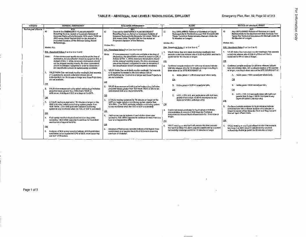
TABLE R - ABNORMAL RAID LEVELS I RADIOLOGICAL EFFLUENT Emergency Plan, Rev. 59, Page 33 of 313
Category GENERAL EMERGENCY SITE AREA EMERGENCY ALERT NOTICE OF UNUSUAL EVENT
Rodioslogcot Effluents RG11 RS1 RAl RUlIC Dose at the EMERGENCY PLAN EOUNDARY IC Dose at the EMERGENCY PLAN EOUNDARY IC Asy UNPLANNED Release of Gaseous or Liquid IC Asp UNPLANNED Release of Gaseous er Liqoid
Resuiltfeg from as Actual or imminent Release of Resuiltig froam as Actoat or Imminent Release at Radioactivsity to the Essireomeet that Exceeds 200 Radioactivity Is the Ensironmeot that Exceeds TwoGoseoss Radloastivity Exceeds 10011 moom TEDE or Gaseoss RadloactWiity Exceeds 101 mrorm TEDE or Times Technical Rsrjsrioemects Macsal Limits foe Times the Techrsical Requtrements Macsal Limits far51001 mrem Child Thyroid CDE for the Actual or 5OD mrem Child Thyrord CDE for the Actual er IS Minotes or Loager. ES Minutes or Longer.Projected Duration of the Release Using Aetual Projected Duratioa of the Release.Meteorology. Modes: ALL Modes: ALL
Modes: ALLModes: ALL EAL Thresheid Value (I or 2 or 3 cr 4) " AL Thresheid Voice (1 or 2ZerO c r4)
GAL Threshold Vaise (1 or 2or 3or 4 cr 5)SAL Threshold Voice (1 or 2 or 3 or 4 er 5) 1. VALID Noble Gas sent stech monitoding reading(s) thot I. VALID Noble Gas soot slosh moollor roadiog(s) thet esceedo
Note: If nose assesnmest rosolls are onoaiblae at the limo of . esceeds sallie total estesse t'ale of 2.OEsE isCldnin ond ihat Is a total site relsone rate oi 2.00+0 i.Cilsmns and thaot isNote: lf dose essesoment rsullsamrasafflabloeoflbselime of deolamtiun, lbseolassifiootion should beaheoundEcAL 2 sustcined far 15 minutesa or longer. sustained for 6it imantes or looger.
deofarstion, lbs efassitisaaios ohoold ho booed on GAL 2 instead ofFGAL 1. Whi/e neocesoay desiftsafons shsuldJnstead ofFALl1. Whife necesoary declarstians should cot be delayed awaiting resolto, lire doss assassment O5 O.RRnot be deloyed awuilny rosulls, lbs dose asosesmeot should be initilated/osmpfeted in sorder to determine if
hshuldhbe Inilfated/completedlin orderlao dclesrolce If Ihe olassillcation oshould ha suboequently escafeted. 2. Ccotoired sample asalyoses tor airborne releoses indicate 2. Contirmed sample analyses for airborne releases Indicatefirs classification should bs saboeqoently escalated. lotSal sto release rates tsr 15 minutes or tongor resuitelg In total site reiease tales, with a release duration of tO minultas
1. VALID Noble Gas sent otach monitor reading(s) thal eccoeds dose tales ol lbs SITE BOUNDARY of: or longer, resultilng Is dote mises at the SITE ECUNDARY of:1. VALID Nnbie Gas nest otocin monitor reading(s) that eacaeds or Is exprected to enceed a oist lotol relense tote of
or is enpected to exceed a cite tolta rolease rote of s.2En~g.Cllmln for 15 minutes or longer sod Dose Praocetions A. Noble gases > 1,0iE+5 mreranyear whole body, A. Nobie gases >1000 mroranyeor whole body,6.2E+tipCtmio fori15 minutes or tonger sod Dose Projections are cot anailabfle.ame sot availoble. OS OR
ORRO 2. VALID dose asesosamnin axing atusal meteorology lrI noites S. Noble gases> 0 .05+5 inremlysor chin, B, Noble gases >60001 morrolyoaroskdn,
2. VALID dose asosossment osog octual meteorology lodlcates projeoctd doses greater tbao 100 morero TEDS 0 5110 irmrarRprojectert doses greater than 1000 srresm TEDS or ohiid thyroid COO at or beyond tine EPS. O ~0000 mremn child thyroid CDE xi or beyond lbs EpB. C -3,63,H3adpriuae ihhIie
OR grea1ter thao3 -3 days particulatesryr w Ish hafvsy greater thon 8 dsys > 30011 mmmfmyearlto anyO...RR reaer han8 dys >.gB5 ttemyea toanyorgan (lohalotioa pathway ooly).
S.AVLI edigssole3or.~~ A VALID reading sustained lori15 minuts or lsnger on the organ (Inhalation pathways only).3. VAID eadng ustine fo 15rn~u is orriger en thes RME perimeter radiation monlitodng system greater than O
RMS perdmeter radiation msoatodng system greater thas 1iOmrnPhr. (The RMS porimeter radiotios monltodng system OR1000 mR/hr. (The RMO pedimeter radiation monitoning is only montilord whon the TSC or S=OF s activated) S. Confirmed sample analyses for liquid releasas Indicatesystem is eoly monitored when the TOC or SOP is sotisated) . coiretomlonysso:iqdreaonoduo noaenfrelions with a release duratos of tO mloutes or
ORs3. conrsirmdsamp is naoyses ofo 200u two estes Teohicate longer in excess of two limes the Technical RequirementsOS ocnrtosI xeso 0 ie h ehia Manual liquid effloent linits.
4. FIeld survey results Indicate closed wlndsw dose sates Reqoirements Manuel liquid effluent limits lori15 minutes or4. Filed survey mesults indicate closed wisdom dose totes enceding 100 mR/hr eupected Iaocontinue for morn thxs one longer.
exceeding 10011 mRthrr eopeoted lx continue for more than boar ol or beyond tins SPB,ens boor of or beyond the SFB.O R
OR - 4., VALID reading ox oany liquid eflouent monitor thai exceeds 4. VALID reading on any liquid effluent monitor thot enceods
0. nayse o fod orvy omyesindoos cil ibrod dse two hundred limes the alarm selpoini established by a con-cot two limes lire aons sutyolnt nstablisbed by a current5.AalssofSldsreysmle ndct cid hr 5dds Anmalysesta or bdsuvyasdmthes E ndcat sf000 m hrem d a ossuin radlnac[tyt discharge pormit lori"[ mioutes or longer radioactivity discharge permit for 601 minutes sr longer
commitment ot or besyond the GPO of 5000 mrem assuming ase hoar of inhalation.one boor of Inhalation.
Page 1 of 3
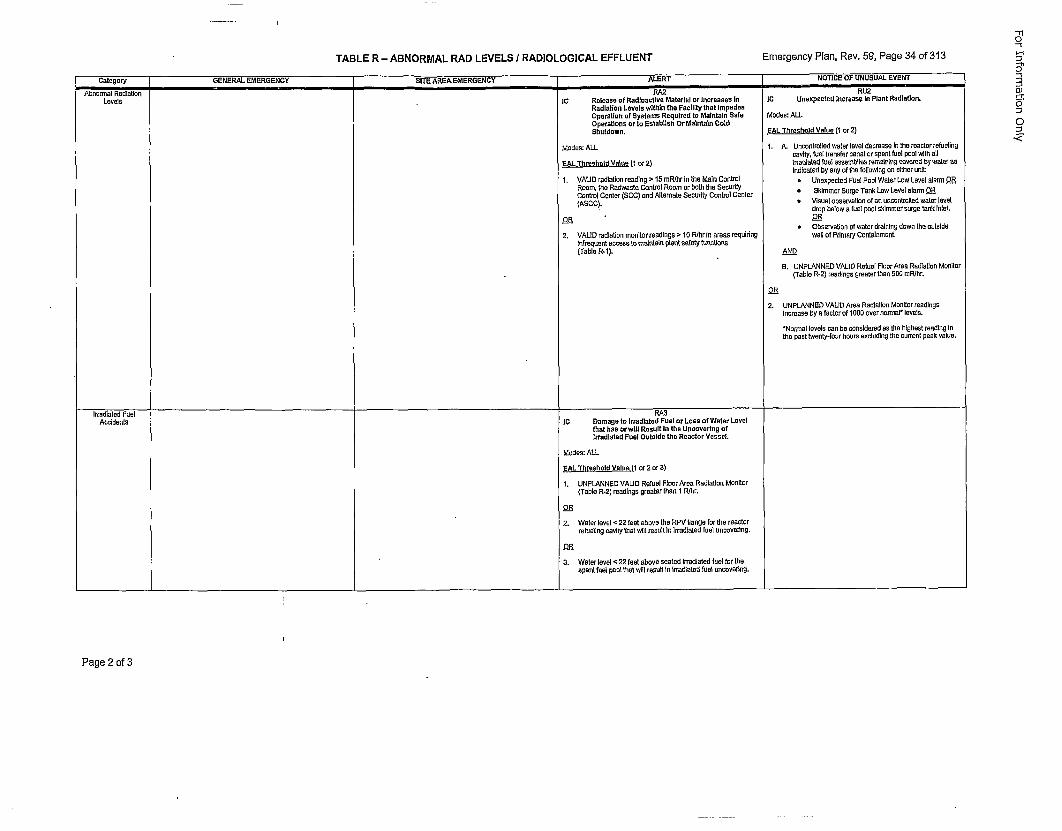
TABLE R - ABNORMAL RAD LEVELS I RADIOLOGICAL EFFLUENT Emergency Plan, Rev. 59, Page 34 of 313
Category GENERAL EMERGENCY SITE AREA EMERGENCY ALERT NOTICE OF UNUSUAL EVENTAirnonnal Radiation PA2 RU2
Levels IC Release of Radioactive Material or Increases In IC Unexpected lnoreasp In Plant Radiation.Radiation Levels w~thIn the Facil~ty that ImpedeeOperation of Systems Required to Maintafn Safe Morten: ALLOperatiees or to !Estahllsh Or Matntain ColdShutdown. CAL Thrreshold Value (1 or 2)
Modes: ALL 1. A. Unovatrolled waler lever decrease in tihereactor refuelingcavity, feel transfer nanal or spevt fuel pool wirh all
CAL Threshold Value (1 or 2) Ireadlsled fuel asserblihes remanfliixg covered lay water usIndicated by any of lire following en either unit:
1. VAUD radiatIon reading > 15 mR~hr in tihe Main Control * Unexpected Feel Pool Waler Low Level alnrm ORRoom, lire Radwaste Control Roomeor both lire Security SkmeSugTo Lweellrm2Control Center (6CC) and Alternate Security Control Center SimeSrgTa owLelar O(ASCO). * Visual irservatlon of an usconarolled waler level
drop below a fuel pool skimmer sarge lock Inlet,
• Observaton ef waler draining down irs oatslde2. VAUD rdlationmonitor reodingsv• 10 R/irrln sarea requiring wuillofFdmery ContaiomenL
Infrequent enoess to mraivtvrn plant safety functions(Table R-l). AND
B. UNPLANNED VALID Refuel Floor Area Radiatioan Monitor(ruble R-2) reodirgs greater Iron 500it nrEiir.
2. UNPLANNED VALID Area Radiation Monitor readingsIncrease byea factor of IE00 over normal* levels.
• Normal levels nun be censidered en lire highest reading Inhea past twenty-fear hosurs exolclding tire current peak nolse.
Irradiated Fuel leA3Accidents IC Damage to irradIated Fuel or Less of Water Level
that has or will Result In Ihe Uueovenleg oftrradiated Pool Outside the Reantor Vessel.
Modes: ALL
CAL Threshold Values ( or 2 er 3)
1. UNPLANNED VALID Refuel Ftoor Area Radiation Monitor(Table R-2) readings greater than t R/irr.
25
I2. Waler level < 22 feet above tire RPV flange for the reactorrefueling needy trot wilt1 result in irradiated fuel uncovering.
2. Waler level < 22 feet above seated irrudiated fset for tirespent feel poolt tirat w~ll• result ln Irradiated fuel uncovering.
"TI0
-e
0
Dr
0.
Page 2 of 3
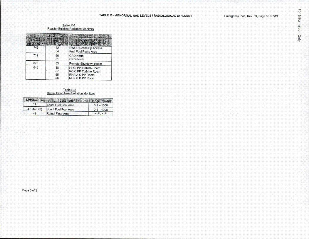
TABLE R - ABNORMAL RAD LEVELS / RADIOLOGICAL EFFLUENT Emergency Plan, Rev. 59, Page 35 of 313
'1
-1
0J
0*
0<
Tabl1e R-1Reactor Buildingq Radiation Monitors
54 Fuel Pool Pump Area719 50 CRD North_______ 51 CR0 South
670 53 Remote Shutdown Room645 48 HPCI PP Turbine Room
57 RCIC PP Turbine Room55 RHR A C PP Room
_____ 56 RHR B DPP Room
Table R-2Refuel Floor,.Area Radiation Monitors
14 S~pent Fuel Pool Area ~ 0.1 -100047 (44 U-2) Spent Fuel Pool Area 0.1 - 1000
49 Refuel Floor Area 102- 10o6
Page 3 of 3
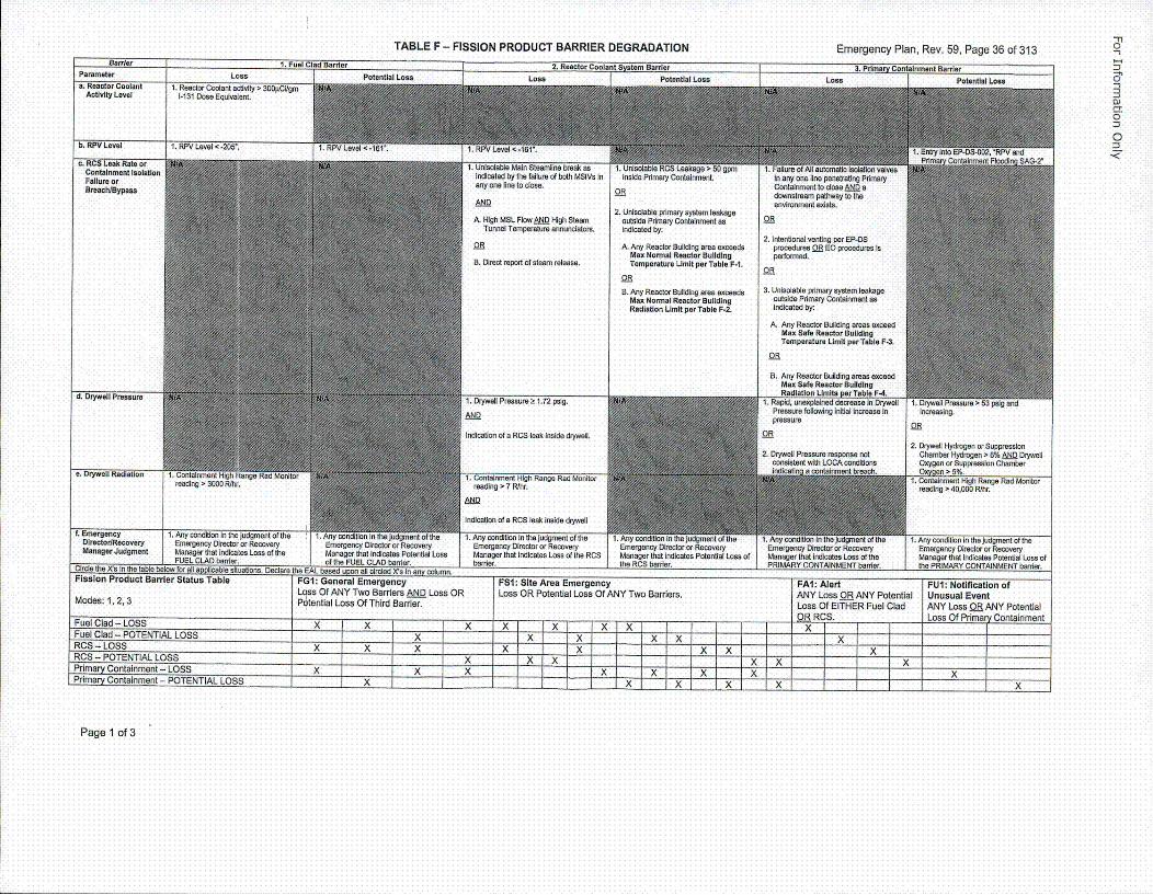
TABLE F - FISSION PRODUCT BARRIER DEGRADATION Emergency Plan, Rev. 59, Page 36 of 313Barrier 1. Fuel Cied Barrier 2. Reactor Coolant System Barrier 3. Prime CnainenBre
Parameter Loss P•f=nfl•l I ^•a I ~ I I Oa t.. lol !a. Reactor Coolant 1. Reactor Coolant adivity > 300iiClIgm
Activity Levei 1-131 Done Equivalent.
!-ri
oJ
0J
C
0. KYV LeVel 1. t, y Level <-205".
c. RCS Leak Rate orContainment isolationFailure orBreachlaypaea
d. Dryweil Pressure
e. Drywell Radiation
• J . ... ... ... .. . . .1. unl5OlflDiO Main •taamllne ornac an 1. Unnlctacie nuo5 L eaxg >indicated by the failure of both MSIVa In inoida Primary ContalhmeotL
any one lione to dose. i0 any one0line penntratng PrimaryConlainranet to dose AN adownstream pathway to ihaenvkonmast errata.AND
A. HIgh MSL Rlow A•Q HIgh SteamTunndi Temperature aenuncators.
2. Unlistable prhmary system leakageoutalde Primary Conolinrnont anIndicated by:
A. Any Reactor Building eros enceedeMax Normal Reactor BuildingTemperature Limit per Table F-I.
2. Intentional venting per EP-DSprocdadras OS EO procedures Isperformed.
B. Direct report ot steam release.QR
ORB, Any Reactor Building eros exceeds
Max Normal Reactor BuildingRadiation Limit per Table P-2.
3. Unlsotable primary system leslakagroutside Prdmary Contialrontn anindiceted by:
A. Any Reacto Building areas exceedMax Safe Reactor BuildingTemrperature Urnit per Table F-3.
1. Drywall Prexturen 1 .72 pstg.
B. Any Reactor Building areas exceedMax Safe Reactor BuidldigRadiation U~mits per Table F-4.
1. Rapid, unexplaIned decrease in Dryetilpressure tollowing loitial increase inpressure
Mandiagerion nbenLs of he RCS eknsddret
2. Drywall Hydraoge or SuppressionChamber Hydrogen > 6% AND Drywall
SOxygen or Suppression Chambern Oxye 5%.
•1. Coctustnmen High Range Reid MonriorSreading >040,000 R/hr.
f, EmergencyDirectodResoveryManager Judgment
I...... ............ ...1.0 oocni ilogeto rEmergency Direc tor or RecoveryManager that indicates Lone of the S Emergency Director or Recovery r1. Any condition in the Judgmnent of the
Emergency Director or Recovery
0mmdi the )(S In Ore rabie betow fo all applicable situations. Declare the EAL based upon all rdirded XCa In ann cotamns. _______________________ _________ ________Fission Product Barrer Status Table FGI: General Emergency FSI: Site Area Emergency FAI: Alert FUI: Notification ofLoan Of ANY Two Banriors AN Loss OR Loss OR Potential Loss Of ANY Two Barriers. ANY Loaa OR ANY Potential Unusual EventModea: 1, 2, 3 Potential Loss Of Third Barrier. Loan Of EITHER Fuel Clad ANY Loss OR ANY Potential
0_• RCS. Ls fPie otimnFuel Clad -LPOTENIA LOSSXX X ......X X "X X X X
RCS -POTENTIAL LOSSxPrimary Containment - LOSS ...... X X X X X XXPrimary Containment - POTENTIAL LOSS
X
Page 1 of 3
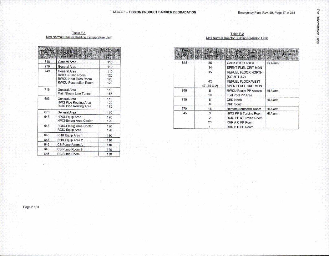
TABLE F - FISSION PRODUCT BARRIER DEGRADATION Emergency Plan, Rev. 59, Page 37 of 313-F10-1
oJ01
Table F-IMax Normal Reactor Buildingq Temperature Limit Table 1F-2
Max Normal Reactor Building Radiation Limit
818 General Area 110779 General Area 110749 General Area 110
RWCU-Pump Room 120RWCU-Heat Exch Room 120RWCU-Penetration Room 120
719 General Area 110Main Steam Line Tunnel 157
683 General Area 110HPCI Pipe Routing Area 120RCIC Pipe Routing Area 120
670 General Area 110645 HPCI-Equip Area 120
HPCI-Emerg Area Cooler 120
645 RClC-Emerg Area Cooler 120_____RClC-Equip Area 120
645 RHR Equip Area 1 110645 RHR Equip Area 2 110645 OS Pump Room A 110645 CS Pump Room B 110645 RB Surnp Room 110
818 3514
15
CASK STOR AREASPENT FUEL CRIT MONREFUEL FLOOR NORTH(SOUTH U-2)REFUEL FLOOR WESTRPENT FUEFL CHIT MON
Hi Alarm
4247 (44 II-2i
749 8 RWCU Reciro PP Access Hi Alarm
10 Fuel Pool PP Area _________719 5 CRD North Hi Alarm
6 CRD South________670 16 Remote Shutdown Room Hi Alarm645 3 HPCI PP & Turbine Room HI Alarm
2 RClC PP & Turbine Room25 RHR A C PP Room
______ 1 RHR BD PP Room _______
Page 2 of 3
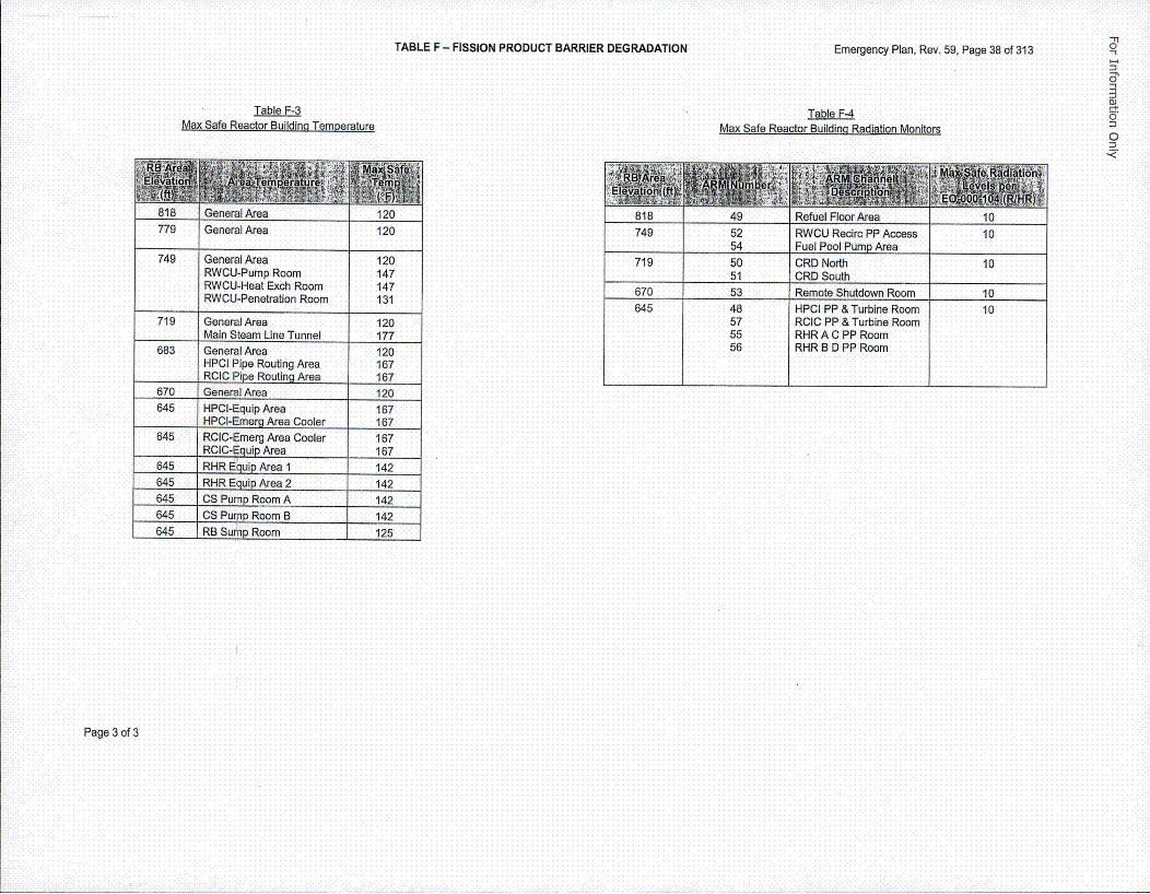
TABLE F - FISSION PRODUCT BARRIER DEGRADATION Emergency Plan, Rev. 59, Page 38 of 313 -I
0"
*O103
0
Table F-3Max Safe Reactor Building Temperature
Ta_.ble F-4Max Safe Reactor Building Radiation Monitors
t1o eealAe 2
818 General Area 120
779 General Area 120
RWCU-Pump Room 147RWCU-Heat Exch Room 147RWCU-Penetration Room 131
719 General Area 120Main Steam Line Tunnel 177
683 General Area 120HPCI Pipe Routing Area 167RCIC Pipe Routing Area 167
670 General Area 120645 HPCI-Equip Area 167
HPCI-Emerg Area Cooler 167645 RCIC-Emerg Area Cooler 167
RCIC-Equip Area 167645 RHR Ec~uip Area 1 142
645 RHR Equip Area 2 142645 CS Pump Room A 142645 CS Pump Room B 142645 RB Sump Room 125
749 5254
RWCU Recirc PP AccessFuel Pool Pump Area
10
719 50 CR0 North 10_________ 51 CRD South _______
670 53 Remote Shutdown Room 10645 48 HPCI PP & Turbine Room 10
57 RCIC PP & Turbine Room55 RHR A C PP Room55 RHR B 0 PP Room
Page 3 of 3
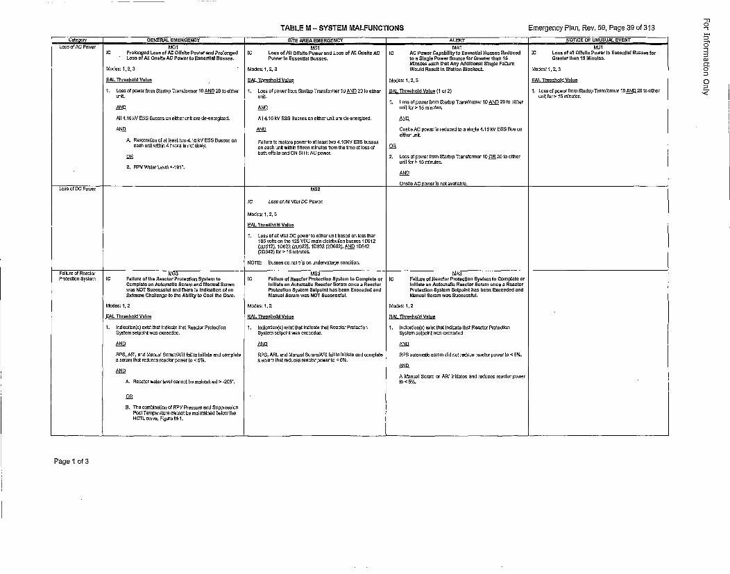
TABLE M - SYSTEM MALFUNCTIONS Emergency Pian, Rev. 59, Page 39 of 313Cate~osr GENERAL EMERGENCY SITE AREA EMERGENCY ALERT NOTICE OP UNUSUAL EVENT
LOSS 01 AU(. Power MG1IC proloeged Loss of All Offolte Power and Prolonged•Less of All Onslte AC Power to Essenotia Basses.
Modes: 1,2, 3
EAL Threshold Value
1. Loss of power" from Startup Transformer 16 AND 20 to eItherunit.
AND
All 4.16 kV ESS Suosoes on elther coil are de-cnerglzed.
AND
A. Restoration of of [coot Iwo 4.16 OV E$8 Bcssoo 00each soil mimhin 4 hours is not likely.
MS1IC Loos of All Otfflte Power End Laoss of All Ocolte ACPower to Essential Easoes.
Modes: 1, 2, 3
EAL Threshold Value
1. Loss of power from Slarlup Transformeor 10 AND 20 to elthorunit,
AND
All 4.16 kV 555 Bussos on either coil are de-energized.
Failure to restore power tooat leasot Iwo 4.16KV 088 busseson each soil wilhin ffeen minuates from the time of loss ofboth offslte and ON SITE AC power.
ICMA1
AC Power Capability to Esosentla[ Nooses Redocedtooa SIngle Power Soarce for Greater than 10Minutes sach thot Ann Additional Sloole PoltureWoald Resutlt n Station Eloloatku
fModes: 1, 2, 3
EAt. Threshold Valoe (1 cr 2)
1, Loss of power from Startap Tranuforner 10 AND 26 to olther
coil for>• 15 minuteu.
AND
Onsfto AC purser as redaced le a singtle 4.16 kV ESS Ecu oo.Reithor urit.
2. Loon of power from Stortop Transformer 10 OR 20 to either
anit for > IS minotes.
ANDO
MU1IC Loss of all Offolte Power Is Essootiot Bosses for
Greater than 10 Mioutes.
Modeol 1,2, 3
EAL Thlreshold Vatoe
1. Loss of powor from Storlop Trsnsformer 10 AND 20 Is eitherunit for • 15 minutes.
6. RPV~doler Level <-101".
LOSS of DC Power MS2
IC Loos sf All Vitof 00 Power,
Modes: 1, 2,23
EAL Threshold Value
1. Losa of all nital DC power Is either unit based on lass thar1015 nolts om te 125 VOC main distdbhution buoses 10612(20612), 1D622 (20622), 106322(20622), AND 10642(200642) for > 15 mlnutes.
NOTE: Eusses do nulltri on undervnltage conditioo.
r-aliUre asrsceacarrPmetectloo System IC Poitore of the Recolor Praoeotton System toComplete an Automotio Scram and Moocat Scramwas NOT Saccessfel end there Is Jodlestcon of acEstreme Challenge to the Abilttty to Coot the Core.
Modes: 1, 2
EAL Threshotd Valce
1.uIdicalion(s) eoistlthatlindlcate Ihot Reactor PraleotionSystem selpoint was eoceedad.
ITPS, ARI, end Manual Sormm/ARI fall to initlate end complete
a scram Oral reduces reactor power to <65%.
A. Reoctor water level carnot tbn maintained > -265"¶
OR
0. The combination of RPV Preosure and SuppressionPool Temperature cannot bc maintained below theHCTL comve, Figurc M-1.
IC PFilure of Reactor ProtectIon System to Camplete orInitate an Astomatic Reactor Serom ocne a ReactorProtection Syatem Setpolnt has been Eacoeded andMacuaol Scram mas NOT Soccessfat.
Modes: 1, 2
EAL Threohold Value
1. Indicatlor(s) euist thot indicate that Reactor Protecllon
Syotem octroint woo exceeded•
AND
RPS, ARI, and Manual ScrsrrdARl tail to initiste and completesscram Oral reduces reactor power to <05%.
IC
Modes: 1,2
EAL Threshold Valuee
1. IndicatIon(s) esist that indicate thstl Reactor PretectionSystem ontpoint was exceeded
AND
RPS automatic scrom did not reduce reactor power ts <65%.
AND
A Manoal Scram or ARI nitiaites and reduces reactor powerto <5%.
MA,'Failure of Reactor Protectioc System to Comptete ortoitlate an Aatoma~c Reactor Scram once a ReactorProtectIon System Sctpatnt bes been Boceeded andMancal Scram was OSuceensful.
Page 1 of 3
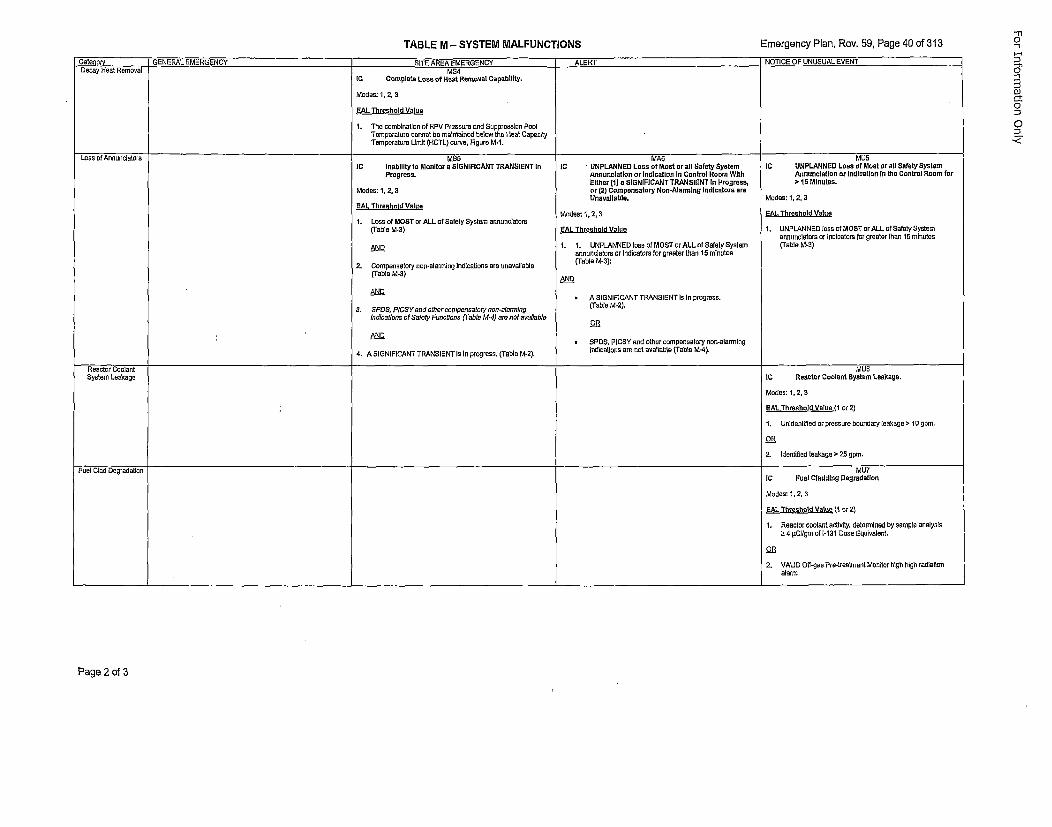
TABLE M - SYSTEM MALFUNCTIONS Emergency Plan, Rev. 59, Page 40 of 313
Catenory GENERAL EMERGENCY SITE AREA EMERGENCY ALERT NOTICE OF UNUSUAL EVENTDecay Heat Removal MS4
IC Complete Loss af Heal Removal Capability,
Modes: 1, 2, 3
EAL Threshold Value
1. The combination of RPV Pressure end Suppression PeelTemperature cannot be maintained below the Heast CapacityTemperatura Umit (HCTL) nerve, Figure M-1.
Laoss of Annuncliaror MS5 MA5 MU5IC InabIlity to Monitor a SIGNIFICANT TRANSIENT In IC UNPLANNED Lace of Most or all Solely System IC UNPLANNED Lose of Moot or all Safely System
Progresa. Anonunlation or Indication In Control Room WIth Anounctatlon or tndloation In the Control Room forEither (1)0a SIGNIFICANT TRANSIENT In Progress, > 1S Minutes.
Modes: 1,2, 3 or (2) Compensatory Non-Alarmdng IndIcators areUnealagable. Modes: 1, 2, 3
SAL Threshold ValueModes: 1, 2, 3 EAL. Threshold Value
1. Loss of MOST nr ALL of Safely System annonoiators(Tablo M-3) EAL Threshold Melee 1. UNPLANNED 1o00 of MOST or ALL of Safety Syatem
annunciators or indicators for greater than 15 minutesAND 1. 1. UNPLANNED loss of MOST or ALL at Safely System (Table M-3)
onnunciateor or Indicators for greater than 15 minoutes2. Compensatory non-olarming indIcations ere unavailbleb (Table M-3):
(Table M-3) AND
AND , A SIGNIFICANT TRANSIENT olei progress.
3. SPOS, PlCS Y end otheroempenoatory aon-abamrrng (Table M-2).
Indlcations of Safety Funotions (Table M-4) eve not available
N• SPOS, PICSY and other compensatory non-alarming
4. A SIGNIFICANT TRANSIENT lo in progresn. (Table M-2). Indications ore aol available (Table M-4).
Reactor Coolant MUS
System Lealkage IC Reenter Coolant System Leohage,
Modes: 1, 2, 3
EAL Threshold Voice (1 or2l
1. Unldeatified or pressure boundary lenkage > 15 gpm.
2. Idendtifed leakage >025 gym.
Peel Clod Dogradation MU7IC Fool Cladding Gegradatlon
Modes: 1,2, 3
EAL. Threshold Valse (.1 or 2)
1. Reactor coolant activIty, determined by somple analysls3 4 p.Ci/gm of 1-131 Dose Equiveleot.
OR
2. VALID Off-gao Pre-treatment Monitor high high radlatisoalarm
Page 2 of 3
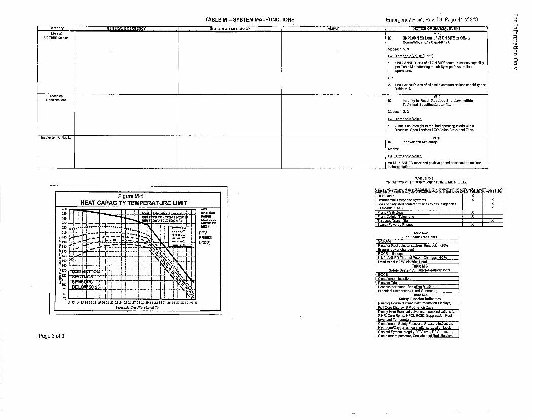
TABLE M - SYSTEM MALFUNCTIONS Emergency Plan, Rev. 59, Page 41 of 313
Caelr/GENERAL EMERGENCY SITE AREA EMERGENCY ALERT NOTICE OF UNUSUAL EVENTLoss of MUS
Communications IC UNPLANNED Loss of all ON SITE or Offslto
Communications Capabilities.
Modes: 1, 2, 3
EAL Threshold Value (1 cr2)
1. UNPLANNED loss of sli ON SITE cammunlcutIons capabilityper Table M-1 affecting the abllty to perform routineoperations.
OR
2. UNPLANNED loss of all slfsile osmmunications cspabllity perTable M-1,
Technical MU9
Speoltications IC Inability ts Reach Required Shatdown wlthth
Teornical Specificatton Limits.
Modes: 1, 2, 3
EAL Threshold Value
1. PlantlIs not brought to required operating mode withinTechnical Specifications LCD Action Statement Time.
Inadvertent Criticality MUI0
IC tnadvertant Criticality.
Modes: 3
CAL Thresheld Vauee
An UNPLANNED extended positUve period observed on oucinurInst rumentatlon.
"-s"
-s
.,i
TABLE M.1,ON SITEJDFFSITE COMMUNICATIONS CAPABILITY
IUHF Radio ______________Figure M-1HEATCAPACITY TEMPERATURELIMIT ___
25 I i i E i
~' ....*t r . e..BOE.3
at-i . ....r--" -s..... .. . l....
1213141 t.• 1 t tt 2g:2t 20.12 42, 23 - 267 2t 29 30313233 34 3536 e3r 3E 3B 4e4
Table M-2SI9lglicant TranstentsSCRAMReactor Reciroulutson system Runbacks (>25%/thermal power changes)EGCS InitiationsUNPLANNED Thermel Power Changons >10 %Load reject > 25% electrical soad
Table M-3SECSa fety System Annun elate rslthdlceteos
IContainment IsoletionRoaster TriProcess ur Etfluent Radiation MonitorsElectrical Dlstrdbutlon/Diesel IGeneratora
Table M-4Safety Fenotirm Indicators
Reactor Power-Nuclear Instmumerntation Displays,Foil Core Display, SIP panel displaysDocay Hest Removal-valee end pump Indications forRHR, Core Spray. HPCI, RCtC, Soppreslsin Poollevet end Temoersatre
Conlelnment Safety Functions-Preuuure indicabion.,Hydrotgen/Oxygen concenlralions, radiation levels,Coolant System lntegdty-RPV level, RPV presusure.,Contalnment oressure, Contalnment Radiation level
Page 3 of 3
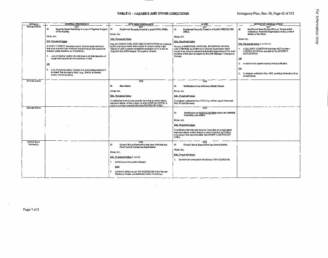
TABLE 0 - HAZARDS AND OTHER CONDITIONS Emergency Plan, Rev. 69, Page 42 of 313
Gate a• GENERAL EMERGENCY SITE AREA EMERGENCY ALERT NOTICE OP UNUSUAL EVENTSecurity Events 0G1 OS1 OAt OU1
IC Security Event Resulting In Lass el Phrysical Central IC Canfirwed Security Event In a pleant VITAL AREA. IC Canfirased Security Event In a PLANT PROTECTED IC Ceefirmede SecurIty Centttoen en Threat whichaf the FacilIty. AREA. tudleates a Poteetlal Degradatlee In the Level a!
Mode: ALL Safety at the Plant.Mode: ALL Mode: ALL
I EAL Threshold Vatae Mode: ALLEAL Threshold Vale EAt Threshold Value
Any oct of SABOTAGE, HOSTAGE OR EXTORTION as confinmed EAL Thresheld Vatue (1 st 2 cr 3)A HOSTILE FORCE has taken control of plant equipment such by Seonuity Supervision which results in actual or I~kely major Any act of SAEOTAG3E, HOSTAGE, EXTORTION OR CIVILthai plant perormenn are unable to operate equlyroent required Is failtures ol plant tunctons needed Ion pmoteclion at the puhili as CISTUREANCE as oontirmed by Security Supervisinn which 1. A SECURITY CONDITION that does NOT involvewaistaln safety fenctions au Indicated by: judged hy the Shift Manager?/ Emergency Director. resulta Inans actual or potential substential degradation of the level HOSTILE ACTION as reported by the SECURITY
of nafety of the plant eo judgedi by Ihe Shift Manager I Emergency SUPERVISION.1. Loss of physical control of a vitel wase sock that operation of Director.
equipment inquired for safe shutdown Is lost.P
OR 2. A credible cite specific security threat notification.
!2. Loss of physical control of spent foal pool coolieg systems If Oimminent fuel damage Ia likely. (e.g., freshly off-Inaded 3. A validated notification from NRC providing Isformetlon of asresctor core Is the pool). elrcraft threat.
Security EvntOS2 0A2
IC Site Attach, IC Notification at an Airbrorn Adtack Threat
Mode: ALL Mode: ALL
EAL Thresheld Melee SAL Thresheld Velee
A notification from the site sonority force that as ensed attsch, A validated onllotiallon from NRC of an aildiner attach threat lessexplosive attack, aidiner impact, or other HOSTILE ACTION is Than 30 minutes away.occurrinn or hss occurred within the PROTECTED AREA.
Security EvnO A3
IC Nottt~catton of HOSTILE ACTION within the OWNERCONTROLLED AREA.
Mode: ALL
EAt Threshold Meloe
A notlficatson from The site Security Force that en ocoed sntack,enplosive adtack, sinlner impact or ether HOSTILE ACTION ineccardeg or has occurred within The OWNER CONTROLLEDAREA.
Control Room 0S4 0A4Evacuetlos IC Control Roam Enaouatien has baeen Initiated end IC Central Rorom Enansatiee has been Ioitiated.
Plant Central Ceannot be Established.Mode: ALL
Mode: ALLE.t Threshold Values
,EAt Threshald Ma ne (1 end 2)1. Control ream evacuation lnilisatd per ON-I 05(2E0)-059.
1. Control room evucuattion Iliiated.
2 Coetroi ot eIther uneit per ON-lf0(250)-0Og at the RemoteShutdows pasels not established within 15 minmates.
-r
n
Page 1 of 3
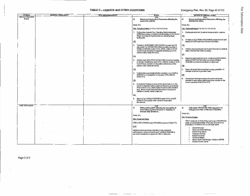
TABLE 0 - HAZARDS AND OTHER CONDITIONS Emergency Plan, Rev. 59, Page 43 of 313
CaeoyGENERAL EMERGENCY SITE AREA EMERGENCY 4ALERT NOTICE OF UNUSUAL EVENT
Events IC Natural and Destrentive Phenomena Affecthng the
plank VITAL AREAS.A
Mode: ALL
PAL Threshnild Value (1 or 2nr 3 nr 4 arE5 orE6)
1. Earthquake at greeter then Operating Easas Earthquake(DBEE) levels based no seismic Ieoteumeotatlsn in the ControlRosin recording level greater then en Operating EasisEarthquake.
OR
2. Tornado or SUSTAINED HIGH WINDS nI greater thsn 80mph within the PROTECTED AREA bnundary resulting InVISIELE DAMAGE to plant VITAL AREA. (Table 0-1 ) ORControl Room Inledoalsa of degraded performaonceof thesystems within those uhroclures.
Os
3. VehIcle crash wIthin PROTECTED AREA boundary resultingin VISIELE DAMAGE to plant VITAL AREAS. (Table O-1) ORConlrol Roorm indication of degraded performance of thesyotems within those structures.
OR
4. Turblne tailure-generaled missiles resulting In any VISIELEDAMAGE to or penetratIon of any plant VITAL AREAS.(TFable 0-1).
Os
S. Uncontrolled Snoorting in ereso of the plant (Table 0-1) thatresults in degraded safety systemn performance us indicatedin the control room or that creates irduestrial safety hazards(e.g., electrIc shock) thet precludes accses necessary tooperate or monitor safety equipment.
Os
6. Report of any VISIELE DAMAGE Is plant VITAL AREAS(Table 0-1 ) canoed by other ntatrat or destractivephenomena.
OU5IC Nateral and Bestruettne Phenemena Affecting thePROTECTED AREA.
Mode: ALL
PAL Threehold Veluee (1 or 2 or 3 or 4 er 5 orE6)
1. Earthquake detected by seismic Instrumentatlon systems.
OR
2. Tornade or SUSTAINED HIGH WINDS greater the an m0rphimpact ON SITE within the PROTECTED AREA.
Os
3. Vehicle creth causing domage to plant structures or systemswithin PROTECTED AREA boundury.
Os
4. Report by plant personnel el an unanticipated EXPLOSIONwithia the PROTECTED AREA resuti~ng in VISIELEDAMeAGE te permnenet structures or equipment.
OR
S. Report of turbIne faluare resultIng In casing penetration ordramage te turbine or gnaerator sesls,
Os
6. Uncontrolled flooding In areas of the plant that has thepotential to effect safety rotated equipment needed far thecurrent eperating mode (Table 0-t).
FIRE I EXPLOSION OAE DUEIC FIRE er EXPLOSION Affect~ng the OperabilIty at tC FIRE w~thtn PROTECTED AREA Boundary eat
Plant Safety Systems Reqeired te Estabiteh or Exttnoulabed wIthin 15 Minutes en Deteotioe.Malntaln Sate Shutdown.
Mode: ALLMode: ALL
PAL Thresbeld ValuePAL Thresheld Volfce
FIRE Is buildings or renes contiguous te asp at the followingFIRE or EXPLOSION in any at the following arees (Table 0-1 ). areas not extinguished within IS minutes nf control moom
notitnatlan or vedticotion of a control moom alarm:AND
* Control StructureAffected osyltem parameter indicotiono show degraded * Diesel Generator Euildingsperformance or plant personnel report VtSIELE DAMAGE to * P5W Pump Housepermanent stractures or equipment within a vital area. * Radwasth Eullding
* Reactor EBuidldgs* Turbine Eulidldgs* Interim Spent Fuel Storage instellation (ISFBI)
* Secudty Contrmi Center
Page 2 of 3
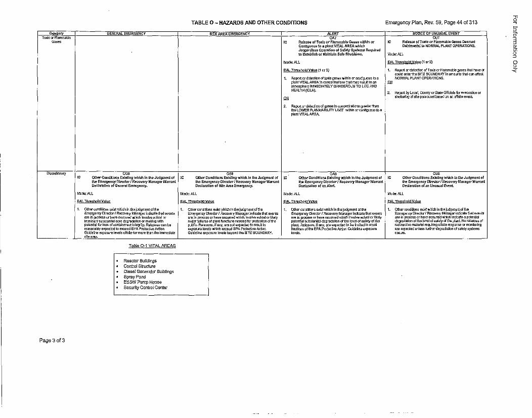
TABLE 0-~ HAZARDS AND OTHER CONDITIONS Emergency Plan, Rev. 59, Page 44 of 313
Cateoryr; GENERAL EMERGENCY ___]SITE AREA EMERGENCY ] -ALERT __ ___[NOTICE OF UNUSUAL EVENT
Gases UPSIC Release of Toxic or Flammable Gases within orCantigeunu te a plant VITAL AREA whichJeopardizes Operatloe at Safety Systems Requiredto Estabtish or Malntain Safe Shutdewe.
Mode: ALL
EAL Threshold Valee 11 cr 21
1. Report or detection of tordo gases wIth~n or contlgusos Is apleant VITAL AREA In corroeniratlions that may result le anasnasphera IMMEDIATELY DANGEROUS TO LIFE ANDHEALTH (IDLH).
OS
2. Report or detection of gases in concentrations greater thanthe LOWER FLAMMABILITY LIMIT within or contIguous tosapleant VITAL AREA.
OUTtIC Release of Toxic or Flammable Gases Deemed
Detrimental to NORMAL FLANT OPERATIONS.
Mode: ALL
EAL Threshold Voice (1 or 2)
1. Report or detectioc of Tordc or Flammable gesos that have orcould ester the SITE BOUNDARY in amounts that coo affectNORMAL PLANT OPERATIONS.
OR
2. Report by Local, County or Sttei Officials for evacoation orshetteriog at site persoonel based on an ostrate event.
0G5 O55 0A5 OU8IC Other Condlitloes Existing which la the Judgment of IC Other Conditioas Existing which ie the Judgment of [C " Other Conditions Existlng which In the Judgment of C Other Conditions Existing which in the Judgment of
the Emergency DirectorlI Recovery Manager Warraet the Emergescy Directorl/Recovery Maeager Warrant the Emergeocy Directerl Recovery Manager Warrant the Emergeney Direciorl/Recovery Manager WarraetDeclaration at General Emengency. Declaration of SIte Area Emergency. Declaration of an Alert. Oeclaratiao of an Unuseal Event.
Mode: ALL Mode: ALL Made: ALL Mode: ALL
EAL Threshold Voiue EAL Threshoid Voice EAL Threshold Vauie EAL Threshold Voice
t. Other conditions mdist which In the judgment of the 1. Other conditioau eutst which in thelJudgmoeni of the 1. Other conditions evist which In the judgmentalf the 1. Other conditions erdst which In the judgroent ofitheEmergency Director I Recovery Manager indicate thot events Emrergency Director/ Recovery Manager Indicate that events Emergency Director I Recovery Munager indicoat that evenis Emergency DirectorI/ Recovery Manager indicate thai eventsare In process or have occurred which Innolve actual or ame In process en heve occurred which involve actual or thkely are In process or have occurred whtoh eInvolv aciual or tikely are in process or have occurred which Inuloete a potentialimminent subatantial core deeradetios or melgng with motor failures of plant functions needed for protection of the potential substantial degradation of= tho tevel at safety at the degwadation ot the level at safety of the planL, No releases ofpotentila for loan of containment Integrity. Raleuses can be public. Releases, if any, rem not expected to result In planL Releeses, if any. are expected to ha limited to small rediaoative materiel requsrdng o[tisite response ar monaitaorgreesonably expected to exceed EPA Protective Action exposure levels which exceed EPA Protectve Action fractioas at the EPA Protective Action Guideline esposure aem expected unless further degrudafion of safety systemsGuideline exposure levels sitsile for more than the Immediste Guideline exposure levels beyond the SITE BOUNDARY. levels. occurs.site owea. ____________________________ __________________________
Table O-1 VITAL AREAS
* Reactor Buildings* Control Structure* Diesel Generstor Buildings* Spray Pondo ES5W Pamp Houseo, Security Control Center
Page 3 of 3
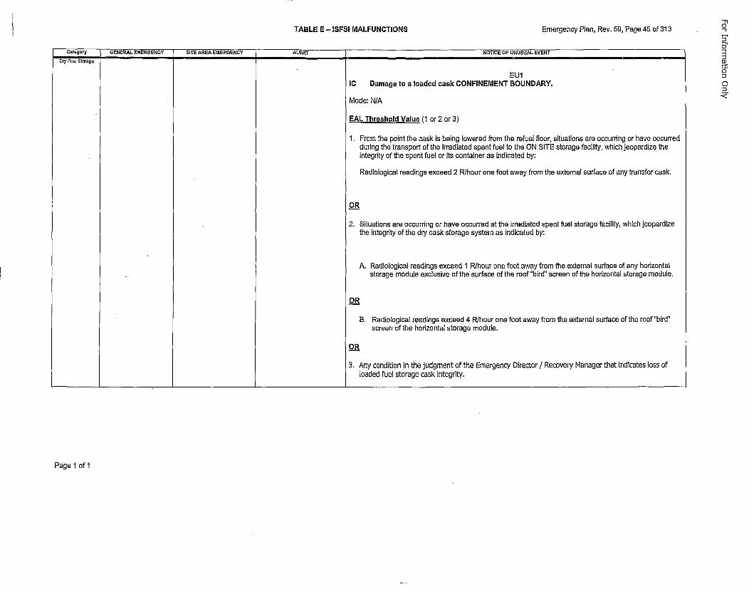
TABLE E - ISFSI MALFUNCTIONS Emergency Plan, Rev. 59, Page 45 of 313
Category GENERAL EMERGENCY SITE AREA EMERGENCY ALERT NOTICE OF UNUSUAL EVENTDr/ Fuel Storge "'"e
EU1IC Damage to a loaded cask CONFINEMENT BOUNDARY.
Mode: N/A
EAL Threshold Value (1 or 2 cr 3)
1.From the point the cask is being lowered from the refuel floor, situations are occurring or have occurredduring the transport of the irradiated spent fuel to the ON SITE storage facility, which jeopardize theintegrity of the spent fuel or its container as indicated by:
Radiological readings exceed 2 R/hour one foot away from the external surface of any transfer cask.
OR
2. Situations are occurring or have occurred at the irradiated spent fuel storage facility, which jeopardizethe integrity of the dry cask storage system as indicated by:
A. Radiological readings exceed 1 Rihour one foot away from the external surface of any horizontalstorage module exclusive of the surface of the roof "bird" screen of the horizontal storage module.
O_.R
B. Radiological readings exceed 4 R/hour one foot away from the external surface of the roof "bird"screen of the horizontal storage module.
o_.R
3. Any condition in the judgment of the Emergency Director / Recovery Manager that indicates loss ofloaded fuel storage cask integrity.
-11a
0-
cJ0"
0]
Page 1 of 1
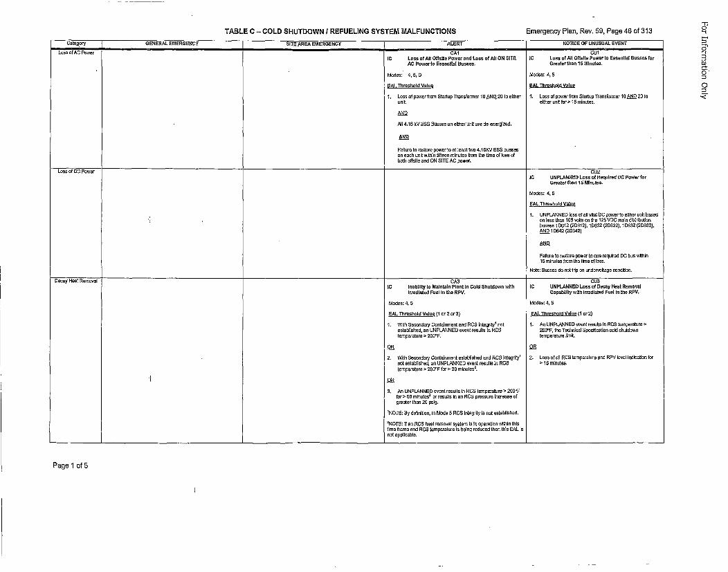
TABLE C - COLD SHUTDOWN I REFUELING SYSTEM MALFUNCTIONS Emergency Plan, Rev. 59, Page 46 of 313
Category GENERAL EMERGENCY SITE AREA EMERGENCY ALERT NOTICE OF UNUSUAL EVENT
Loss of AC Power CA1 CUt
IC Loss of All Offstte Power and Loss of All ON SITE IC Loss of All Offstte Pewer to Esseotial Easses farAC Power ta Esseotlal Easses. Greeter than IS Minutes.
Modes:" 4, B, 0 Modos: 4, 5
EAL Threshold Value EAL Threshold Valuee
1. Loss of power from Startup Traostormer 10O AN.D 20 Is elther 1. Loss of power from Stsduop Transformer 10 AN 20 Isunit. either soil fcr >15 minutes.
AND
All 4.16 kV 255 Bosses on either soil are do-energized.
AN._DD
Failure Is restore power too lt east twa 4.16KV ESS bussesoo each soil within fifees mineutes from the tree of loss of2bat offsite end ON SITE AC power.
Loss of DC Power CU2IC UNPLANNED Loss of Reqoired DC Power for
Greater thsan 1B Miestes.
Modes: 4,05
EAL Threshold Values
1.UNPLANNED loss of oil oital DC power to either onit basedson less thon 10B volts 0n the 125 VDC mote distrbriutios
bussea IDEI12 (2D612), 1DE2.2 (20D62,?), 1DE32 (2DE32),AN.Q 1D642 (20642)
AND
Failure Is rootors power to one required DC bus within15 minutes from lbs lime of lass.
Note: Busses do cot trip on undew/ellage condition.
"-t
Os
or
Decay Heal Removal CA3IC ntabtlity to Malotals Plastc Cn old Shetdwow withtrradiated Feel Is the RPV,
Modes: 4, 5
EAL Threshold Value (1 or 2or 3)
1. With OScoodary Cootatnment and RCS tntegrity' noteslabt[shed, an UNPLANNED event reoults to RCStemperature > 20064.
2R
2. With Secoodary Cootainmonl established and ROB integrity'niotestabtothed, so UNPLANNED event resutloto RCStemprerturs o 200°F for > 20 mtnutes
5.
DR
3. As UNPLANNED event resells in ROB temperoture > 200°Ffor > E0 minutes
2 or results lossn ROB pressuro Increase of
greater lhan 20 pstg.
'NOTE: Ey detinitson, lv Moda 5 RCS integrity localt esteblished.2NOTE: If an RCS heal removal system lts Inoperetion withine thIs
lime frame and RC5 temperature Is baesn reduced then thia hAL issot applicable.
CUSIC UNPLANNED Loss of Decoy Heal Removal
Capab~llty with Irradiated Poet Is the RPV.
Modes: 4, 5
EAL Threshold Valce (1 cr 2)
1.As UNPLANNED eyent results is RCS tnemperature >200°F, lbs Technicat Specificotion cold ohuldowstemperature limait.
252. Loss cf oil RCS temporaltera and RPV level tedicatton for
a 15 minutes.
Page 1 of 5
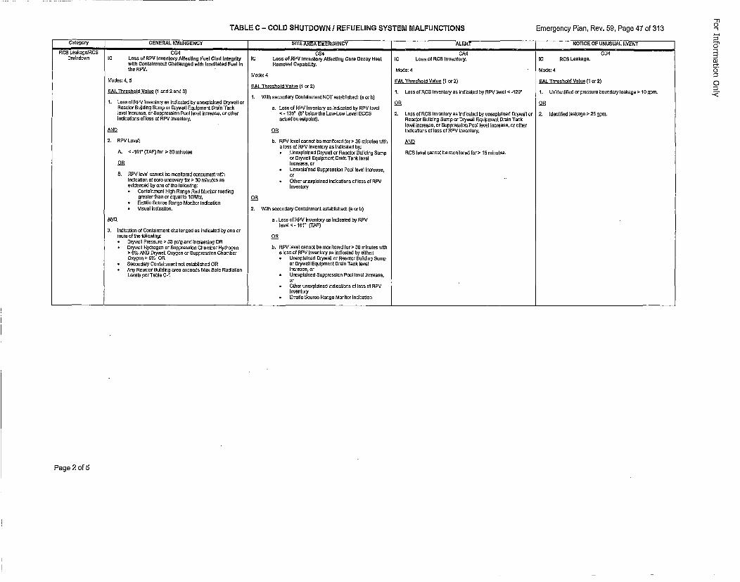
TABLE C - COLD SHUTDOWN / REFUELING SYSTEM MALFUNCTIONS Emergency Rlan, Rev. 59, Page 47 of 313
Category GENERAL EMERGENCY SITE AREA EMERGENCY ALERT NOTICE OF UNUSUAL EVENTRCS Laakago/RCS CG4 C5S4 CA4 CU4
Druindown IC Lass of RFV Inventory Affecting Fuel Clad IntegrIty IC Loss of RPM Inventory Affecting Core Decay Heel IC Loss of RCS lnveatory. IC RCS Lealkageowith Containmoent Challeaged with Irradiated Fuel In Removal Capability.the RPV. .Mode: 4 Mode: 4
Mode: 4Modes: 4, 5 EAL Threshold Value (1 cr 2) EAL Threshold Valee (1 cr 2)
EAL Threshold Value (1 or 2)SAL. Threshold Velue (luand 2 end 1) 1. Laoss of RCS Invontory as indicated hy RPV level < -12E" 1. Usldenlitied or pressure boundary leahage > 10 spot.1. With secondary Conlalnroenl NOT estshlishod: (a or b)
1. Loss of RPM loventory aso indieated by unesplained Dryweil or 23 23Reoctor Euliding Sump or Dryweil Eqeipmoent Groin Tusk a. Loss of RPV Inventory so indicated by RPM levellevel increose, or Suppression Pool level increaseor oiher <- 125" (6" below tha Low-Low Level ECCS 2. Loss of RCS inventoryas indicated byunesplained Dryweallnr 2. tdenifiedleukageo>25 gpro.indicaUlons of loss et RPM Inventory, actoation selpoint). Roaster Euiiding Sorop or Drywall Equiprment Groin Tush
level iscrease, or Suppressios Post level Increase, or otherAND 23 indications of loss of RPV isventory,
2. RPM Level: b. RPM level sunset be monitored for > 3E minutes with AN)9o less of RPM Inventory us lndicated by:
A. < -16" (TAF) for >230 minutes * .Uneexptained Orproell or Readeor Euilding ESuop RCS levol sunset be monitored for >15 minatee.or Dryweil Equipmenot Groin Tusk level2R Increase, or
* Unexpbeinod Suppressioe Pool level Increase,5. RPM level connot be monitored coocurrent with or
Indbsaaion of sore oncovery for >0 34051mnuts as Giber unexplained indications of loss of RPMevidenced by cue of the following: Inventory* Conltanument High Range Rod Monitor reuding
grouter thee or equal to 10iR/hr, 23* Erratic source Rouge Monitor Indication* Misual indication. 2. With secondary Contoinmeont established: )a or b)
AN.D e. Loss of RPM inventory as indcseled by RPVlevehOl <-l6" (TAP)
3. ludination of Centainroent shuilengod an indicated by one orwere of the following: DR
DryWalil Preroure > 52 pstg end Increesing OR* Drywell Hydrogen or Suppression Chamber Hydrogeu b. RPV level sonnet he monitored for >30 minutes with
> 6% AND Drywlwel DOygen or Suppression Chamber a loss of RPM inventory us Indissted by oither.Oxygen e 5% OR * Unesplelnod Dryweil or Rooster Euilding Sump
• Secondury Conlainwent not establiuhed OR or Drywell Equiproent Groin Tusk levet* Any Reactor Building urea escoeds Mes Safe Radiation increase, or
Levels per Table C-I * Uneoplained Suppression Pool snotl increase,
* ther uneuplained Indications st less 0f RPV
Inventory* Erratic Source Range Monitor Indieaotns
Page 2 oft5
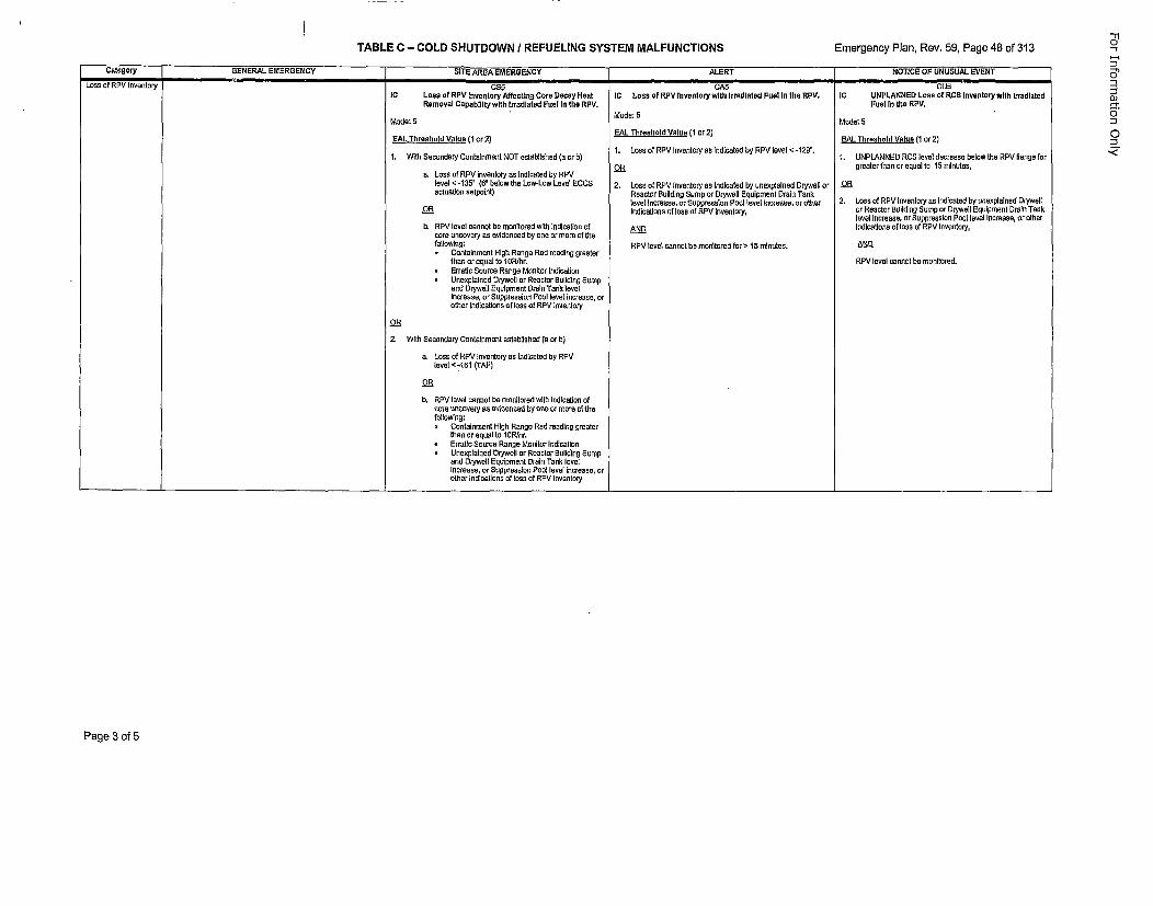
TABLE C - COLD SHUTDOWN / REFUELING SYSTEM MALFUNCTIONS Emergency Plan, Rev. 59, Page 48 of 313
Category GENERAL EMERGENCY SIT'E AREA EMERGENCY ALERT NOTrICE OF UNUSUAL EVENTLoss of RPV Inventory CS5 CA5 CUE
iC Loss of RFV Inventory Affecting Core Decay Heat IC Loss of RFV lnventory with Irradiated Foel Is the RPV. IC UNPLANNED Loss of RCS tnventory wlth IrradiatedRemoval Capablillty wills Irradiatod Fuel In Use RFV. Fool In the RFV.
Mode: SMode: 5 Mode: 5
ELTrsldVle(cr) EAL.Threshold Value (1 or 2) EAL Threshold Valu~e (1 or 2)1. Loss of RPV Inventory as indicoled by RPV level <-125".1.With Secondary Conta~nmnent NOT establlshed (s or b) 1. UNPLANNED RCS level decrease below the RPV flange for
OR greater than or equal to 15 minutes,a. Loss of RPV inventory us Indlcated by RPV
level < -135" (6" below the Low-Low Lovel EGOS 2. Loss of RPV Inventory as Indicated by unexplained Drywall or Oactuation setpoint) Reactor Bul~ding Sumpo or Drywall Equipment Drain Tank
level Inoceane, or Ssppressilon Fooltlevel Inoseaos, or other 2. Loss of RPV Investory' as indicated by snexpalsned DrywellOR Indlcatlons of Ions of RPV Inventory, or Reactor Bul~diog Sump or Drywall Equipment Orals Took
Isvel Increase, nr Suppression Posl level Increase, Or otherh, RPV level cannot he monitiored with Indication ot AND Indications of loss of RPV Inventory,
core uncovery us ehidenced by one or mome nfl thefoilov,'ng: RPV level cannot he monitored flora lb1 m~nutes. N
* Containument High Range Red reading greeterthan or equal to 10R/hr. RPV level cannot be monitored.
* Erratic Source Range Monitor Indication* Unexpalaned Drywell cr Reactor Buildring Somep
and Dryweli Equipment Drain Tank levelincrease, or Suppression Pont level increase, orother Indications of loss of RPV leventnry
2. With Secondary Containment established (a or b)
a. Loon of RPV Inventory as indicoted by RPVlenlv-et 76 (TAP)
OR
b. RPV level cannot be monitored rstlh indIcatIon ofonre snreonvery as ev~denced by coven morme of thefollowing:* Containmoent HIgh Range Rad reading gireater
then nr equal to 10R/hr.* Erratic Snurce Range Monitor Indication* Unexpslaied Orywell or Reactor Buliding Bump
and Drywell Equipment Drain Tank levelIncrease, or Suppression Pool level Increase, orother indications of loss of RPV inventory
Page 3 of 5
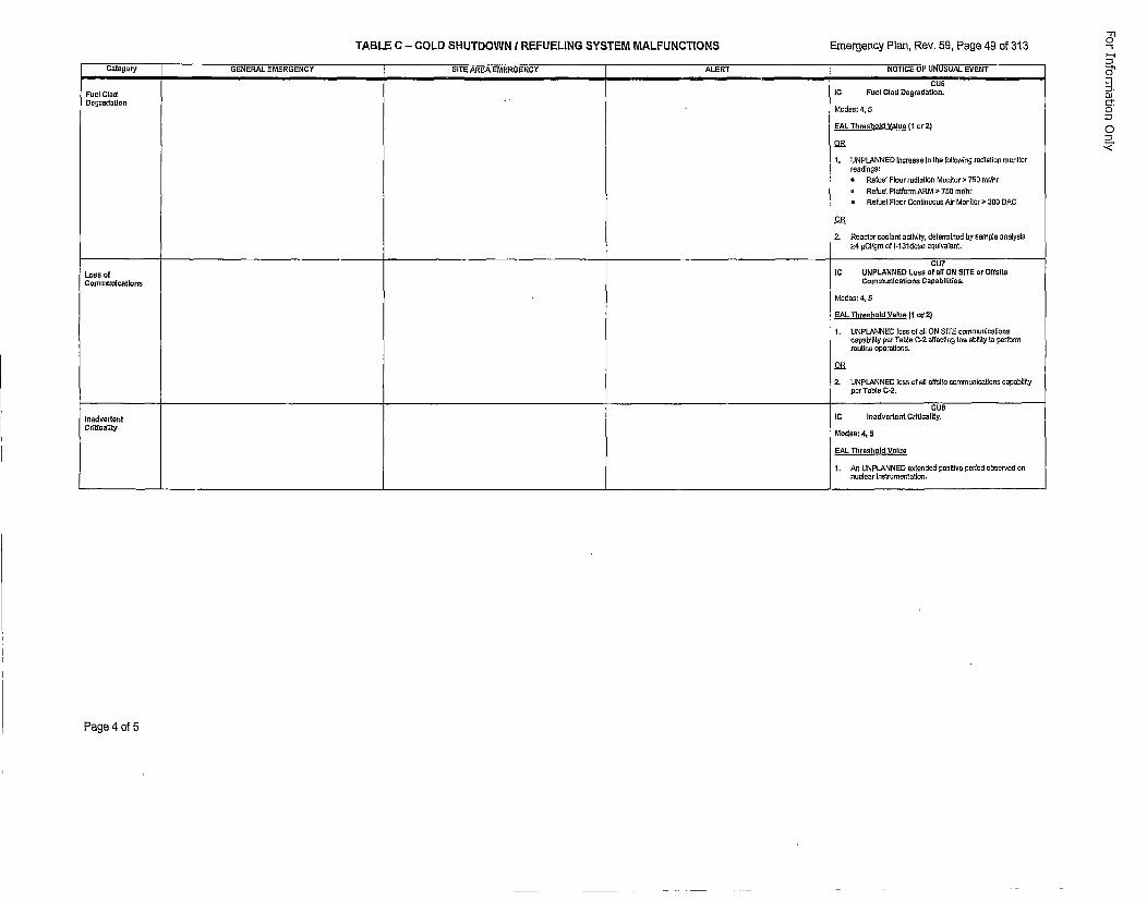
TABLE C - COLD SHUTDOWN I REFUELING SYSTEM MALFUNCTIONS Emergency Plan, Rev. 59, Page 49 of 313
Category GENERAL E=MERGENCY SITE AREA EMERGENCY ALERT NOTICE OF UNUSUAL EVENT
CU6
Fuel Clad IC Fuel Clod Degradation.
DograoltonModes: 4, 5
EAL Threshold Value (1 or2)
Os
1. UNPLANNED Incroase In the following radiation monitorreadings:
* Retoel Floor radlation Monitor > 750 mr/hr
o Refuel Platform ARM'> 750 mr/hr
* Refuel Floor Continouso AIr Monitor ' 300 DAC
Os
2. Reactor coolant activity, dteleninod by sample analysis
>4 IsClfgm of l-13ldose equivabent.
CU7Laoss of IC UNPLANNED LosS sftall ON SITE or OffllteCommunications Communaication Capabllties.
Modes: 4. 5
EAL. Threshold Value (1 or 2)
1. UNPLANNED loss oftali ON SITE communlcalionscapabi~lty per Table C-2 ureding the ability to petformroutina oparations.
OR
2. UNPLANNED toss of all offsile communications capabilitypor Table C-2.
CUBInadvertent IC Inadvertent CrItsoality.Critioality Modes: 4, 5
EAL Threshold Vnlue
1. An UNPLANNED extenrded poslitie poriod observed 0nnoulear lnstm~mentatlon.
'-'r"-s
OJ
0
Page 4 of 5
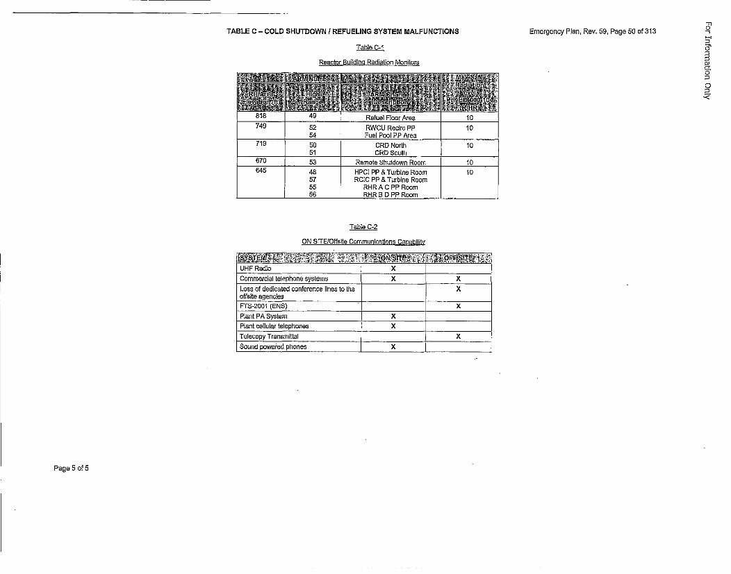
TABLE C - COLD SHUTDOWN I REFUELING SYSTEM MALFUNCTIONSEmrecPlnRv.5,ag50o33Emergency Plan, Rev. 59, Page 50 of 313
Table C-1.
Reactor Building Radiation Monitors
..... t rKeiuei t-Ioot Area 1 l t
749 52 RWCU Recirc PP 1054 Fuel Pool PP Area
719 50 CR0 North 1051 CRD South
670 53 Remote Shutdown Room 10645 48 HPCI PP & Turbine Room 10
57 RCIC PP & Turbine Room55 RHRAC PP Room
_______ 56 RHR B D PP Room ______
Table C-2
ON SlTE/Offsite Communications Capability
UHF Radio XCommercial telephone systems X XLoss of dedicated conference lines to the Xoffaite agenciesFTS-2001 (ENS) XPlant PA System XPlant cellular telephones XTelecopy TransmittalXSound powered phones X
Page 5 of 5
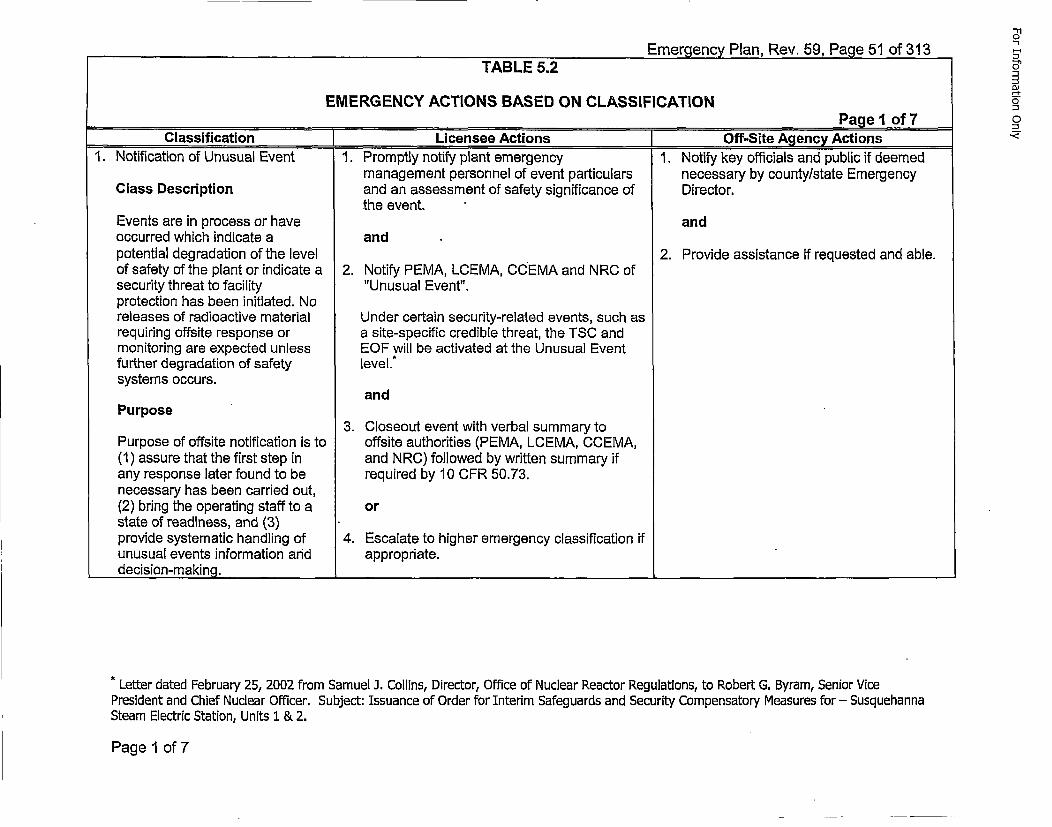
Emergency Plan, Rev. 59, Page 51 of 313TABLE 5.2
EMERGENCY ACTIONS BASED ON CLASSIFICATION____ ____ ___ ____ ___ ____ ___Page 1 of 7
Classification Licensee Actions [ Off-Site iAgency Actions1. Notification of Unusual Event 1. Promptly notify plant emergency 1. Notify key officials and public if deemed
management personnel of event particulars necessary by county/state EmergencyClass Description and an assessment of safety significance of Director.
the event.Events are in process or have andoccurred which indicate a andpotential degradation of the level 2. Provide assistance if requested and able.of safety of the plant or indicate a 2. Notify PEMA, LCEMA, CCEMA and NRC ofsecurity threat to facility "Unusual Event".protection has been initiated. Noreleases of radioactive material Under certain security-related events, such asrequiring offsite response or a site-specific credible threat, the TSC andmonitoring are expected unless EOF will be activated at the Unusual Eventfurther degradation of safety level.t
systems occurs.and
Purpose3. Closeout event with verbal summary to
Purpose of offsite notification is to offsite authorities (PEMA, LCEMA, CCEMA,(1) assure that the first step in and NRC) followed by written summary ifany response later found to be required by 10 CFR 50.73.necessary has been carried out,(2) bring the operating staff to a orstate of readiness, and (3)provide systematic handling of 4. Escalate to higher emergency classification ifunusual events information arid appropriate.
, decision-making._______________________ ______________ _______
5'-
-4,
*Letter dated February 25, 2002 from Samuel J. Collins, Director, Office of Nuclear Reactor Regulations, to Robert G. Byram, Senior VicePresident and Chief Nuclear Officer. Subject: Issuance of Order for Interim Safeguards and Security Compensatory Measures for - SusquehannaSteam Electric Station, Units 1 & 2.
Page 1 of 7
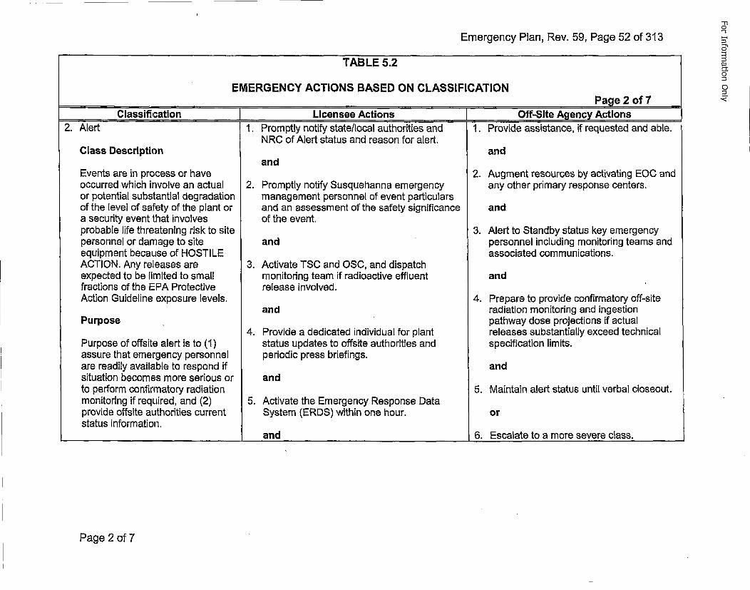
Emergency Plan, Rev. 59, Page 52 of 313
TABLE 5.2
EMERGENCY ACTIONS BASED ON CLASSIFICATION____ ____ ___ ____ ___ ____ ___Page 2 of 7
Classification f Licensee Actions Off-Site Agency Actions2. Alert 1. Promptly notify state/local authorities and 1. Provide assistance, if requested and able.
NRC of Alert status and reason for alert.Class Description and
andEvents are in process or have 2. Augment resources by activating EOC andoccurred which involve an actual 2. Promptly notify Susquehanna emergency any other primary response centers.or potential substantial degradation management personnel of event particularsof the level of safety of the plant or and an assessment of the safety significance anda security event that involves of the event.probable life threatening risk to site 3. Alert to Standby status key emergencypersonnel or damage to site and personnel including monitoring teams andequipment because of HOSTILE associated communications.ACTION. Any releases are 3. Activate TSC and OSC, and dispatchexpected to be limited to small monitoring team if radioactive effluent andfractions of the EPA Protective release involved.Action Guideline exposure levels. 4. Prepare to provide confirmatory off-site
and radiation monitoring and ingestionPurpose pathway dose projections if actual
4. Provide a dedicated individual for plant releases substantially exceed technicalPurpose of offsite alert is to (1) status updates to offsite authorities and specification limits.assure that emergency personnel periodic press briefings.are readily available to respond if andsituation becomes more serious or andto perform confirmatory radiation 5. Maintain alert status until verbal closeout.monitoring if required, and (2) 5. Activate the Emergency Response Dataprovide offsite authorities current System (ERDS) within one hour. orstatus information.
_________________ and 6. Escalate to a more severe class.
1-I
Page 2 of 7
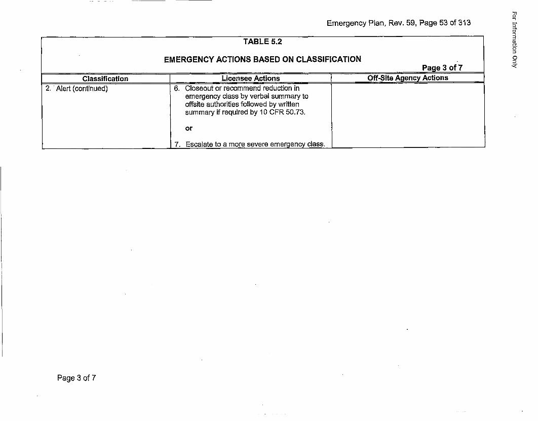
Emergency Plan, Rev. 59, Page 53 of 313
TABLE 5.2
EMERGENCY ACTIONS BASED ON CLASSIFICATION_____________________________Page_3_of 7
cl'assification Licensee Actions [Off-,Site Agency Actions2. Alert (continued) 6. Closeout or recommend reduction in
emergency class by verbal summary tooffsite authorities followed by writtensummary if required by 10 CER 50.73.
or
___________________________7. Escalate to a more severe emergency class. ____________________
-'I
~-t0
--
Page 3 of 7
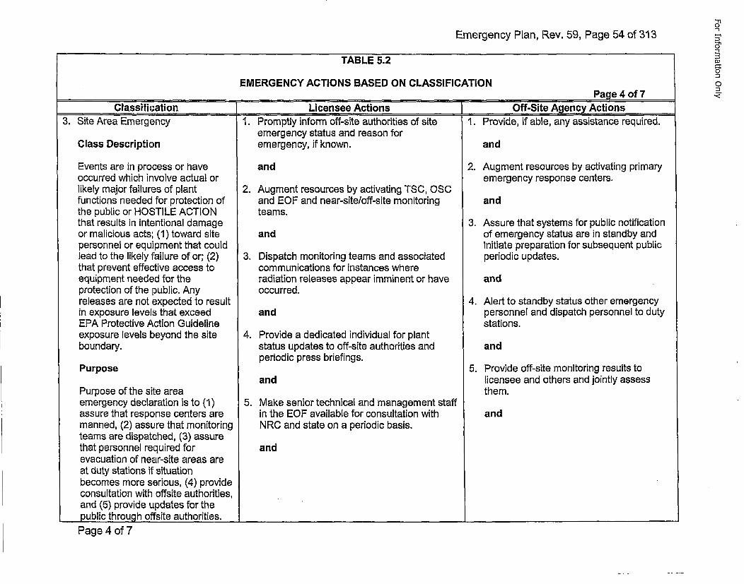
Emergency Plan, Rev. 59, Page 54 of 313
TABLE 5.2
EMERGENCY ACTIONS BASED ON CLASSIFICATION____ ____ ___ ____ ___ ____ ___Page 4 of 7
.Classification [Licensee Actions IOff-Site Agency Actions
on
1DJ
.,<.
3. Site Area Emergency
Class Description
Events are in process or haveoccurred which involve actual orlikely major failures of plantfunctions needed for protection ofthe public or HOSTILE ACTIONthat results in intentional damageor malicious acts; (1) toward sitepersonnel or equipment that couldlead to the likely failure of or; (2)that prevent effective access toequipment needed for theprotection of the public. Anyreleases are not expected to resultin exposure levels that exceedEPA Protective Action Guidelineexposure levels beyond the siteboundary.
Purpose
Purpose of the site areaemergency declaration is to (1)assure that response centers aremanned, (2) assure that monitoringteams are dispatched, (3) assurethat personnel required forevacuation of near-site areas areat duty stations if situationbecomes more serious, (4) provideconsultation with offsite authorities,and (5) provide updates for thepublic through offsite authorities.
1. Promptly inform off-site authorities of siteemergency status and reason foremergency, if known.
and
2. Augment resources by activating TSC, OSCand EOF and near-site/off-site monitoringteams.
and
3. Dispatch monitoring teams and associatedcommunications for instances whereradiation releases appear imminent or haveoccurred.
and
4. Provide a dedicated individual for plantstatus updates to off-site authorities andperiodic press briefings.
and
5. Make senior technical and management staffin the EOF available for consultation withNRC and state on a periodic basis.
and
1. Provide, if able, any assistance required.
and
2. Augment resources by activating primaryemergency response centers.
and
I . Assure that systems for public notificationof emergency status are in standby andinitiate preparation for subsequent publicperiodic updates.
and
4. Alert to standby status other emergencypersonnel and dispatch personnel to dutystations.
and
5. Provide off-site monitoring results tolicensee and others and jointly assessthem.
and
Page 4 of 7I _____________________________________________________________________________
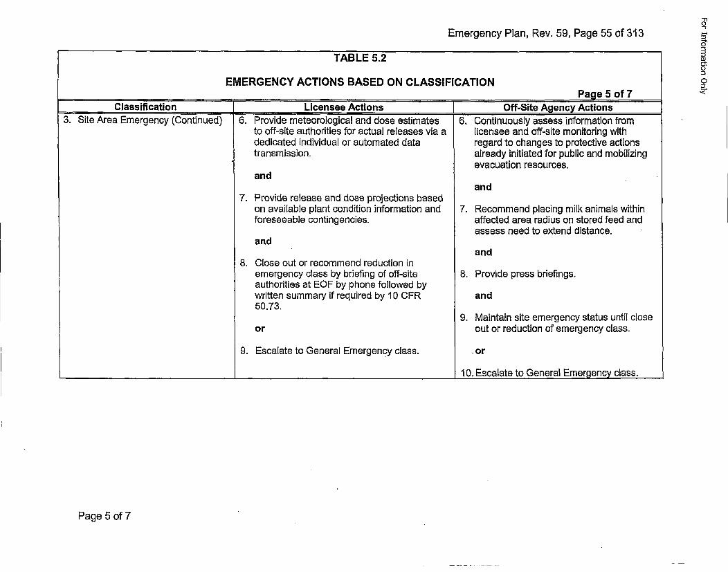
Emergency Plan, Rev. 59, Page 55 of 313
TABLE 5.2
EMERGENCY ACTIONS BASED ON CLASSIFICATION____ ____ ___ ____ ___ ____ ___Page 5 of 7
Classification [Licensee Actions ]Off-Site Agency Actions3. Site Area Emergency (Continued) 6. Provide meteorological and dose estimates 6, Continuously assess information from
to off-site authorities for actual releases via a licensee and off-site monitoring withdedicated individual or automated data regard to changes to protective actionstransmission. already initiated for public and mobilizing
evacuation resources.and
and7. Provide release and dose projections based
on available plant condition information and 7. Recommend placing milk animals withinforeseeable contingencies. affected area radius on stored feed and
assess need to extend distance.and
and8. Close out or recommend reduction in
emergency class by briefing of off-site 8. Provide press briefings.authorities at EOF by phone followed bywritten summary if required by 10 CFR and50.73.
9. Maintain site emergency status until close•or out or reduction of emergency class.
9. Escalate to General Emergency class. .or
___________________________________________________________10. Escalate to General Emergency class.
Page 5 of 7
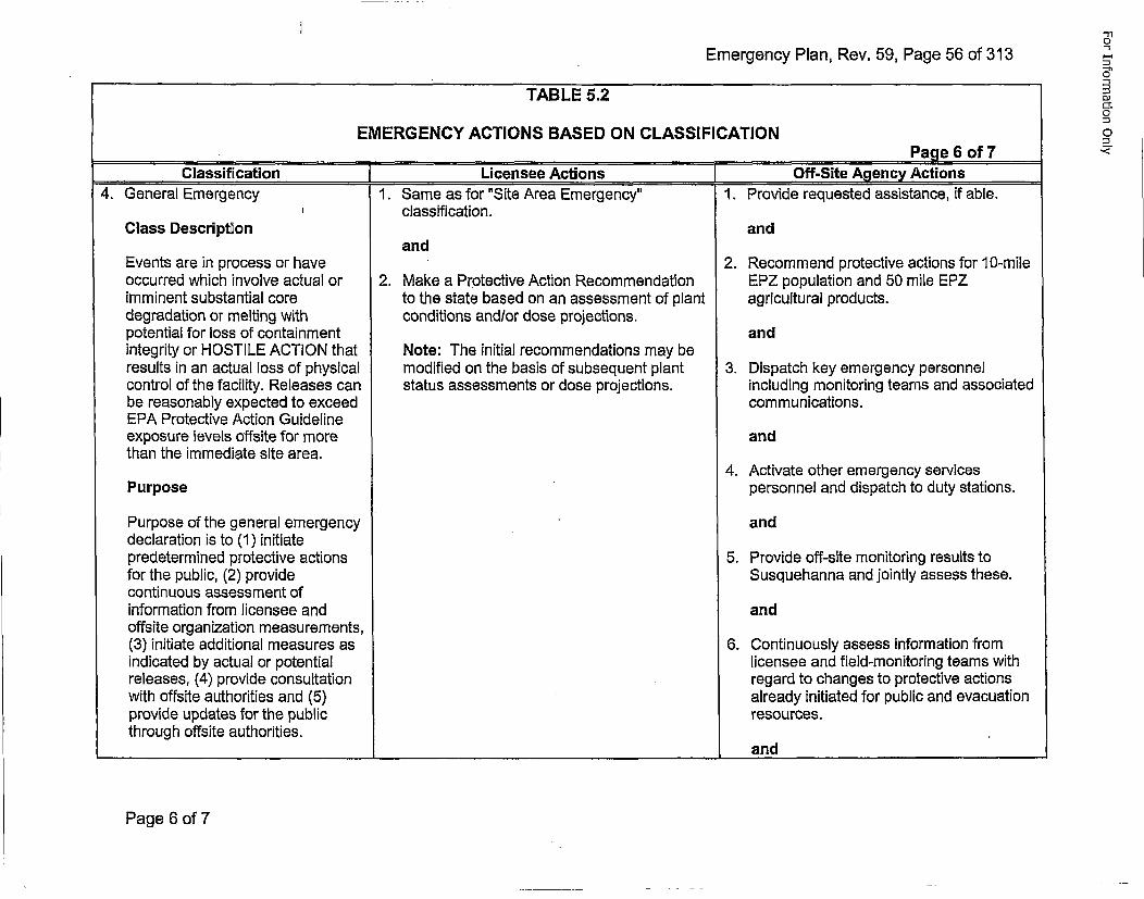
Emergency Plan, Rev. 59, Page 56 of 313
TABLE 5.2
EMERGENCY ACTIONS BASED ON CLASSIFICATION_________________________Page 6 of 7
Classification (Licensee Actions Off-Site Agency Actions4. General Emergency 1. Same as for "Site Area Emergency" 1. Provide requested assistance, if able.
I classification.Class Description and
andEvents are in process or have 2. Recommend protective actions for 10-mileoccurred which involve actual or 2. Make a Protective Action Recommendation EPZ population and 50 mile EPZimminent substantial core to the state based on an assessment of plant agricultural products.degradation or melting with conditions and/or dose projections.potential for loss of containment andintegrity or HOSTILE ACTION that Note: The initial recommendations may beresults in an actual loss of physical modified on the basis of subsequent plant 3. Dispatch key emergency personnelcontrol of the facility. Releases can status assessments or dose projections. including monitoring teams and associatedbe reasonably expected to exceed communications.EPA Protective Action Guidelineexposure levels offsite for more andthan the immediate site area.
4. Activate other emergency servicesPurpose personnel and dispatch to duty stations.
Purpose of the general emergency anddeclaration is to (1) initiatepredetermined protective actions 5. Provide off-site monitoring results tofor the public, (2) provide Susquehanna and jointly assess these.continuous assessment ofinformation from licensee and andoffsite organization measurements,(3) initiate additional measures as 6. Continuously assess information fromindicated by actual or potential licensee and field-monitoring teams withreleases, (4) provide consultation regard to changes to protective actionswith offsite authorities and (5) already initiated for public and evacuationprovide updates for the public resources.through offsite authorities.
____ ___ ____ ___ ____ ___ ____ ___ ___ and
-h5"
0l
0
Page 6 of 7
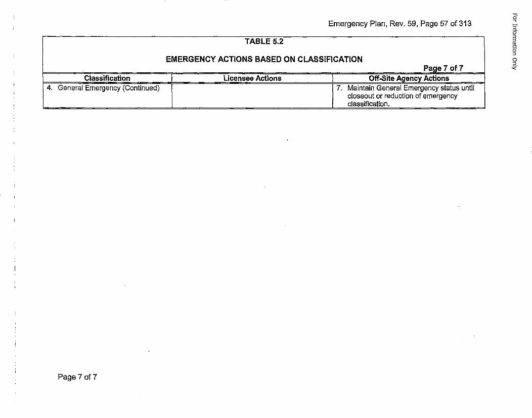
Emergency Plan, Rev. 59, Page 57 of 313
TABLE 5.2
EMERGENCY ACTIONS BASED ON CLASSIFICATIONPage 7 of 7
Classification Licensee Actions Off-Site Agency Actions4. General Emergency (Continued) [7. Maintain General Emergency status untilI closeout or reduction of emergency
.... classification.
Page 7 of 7
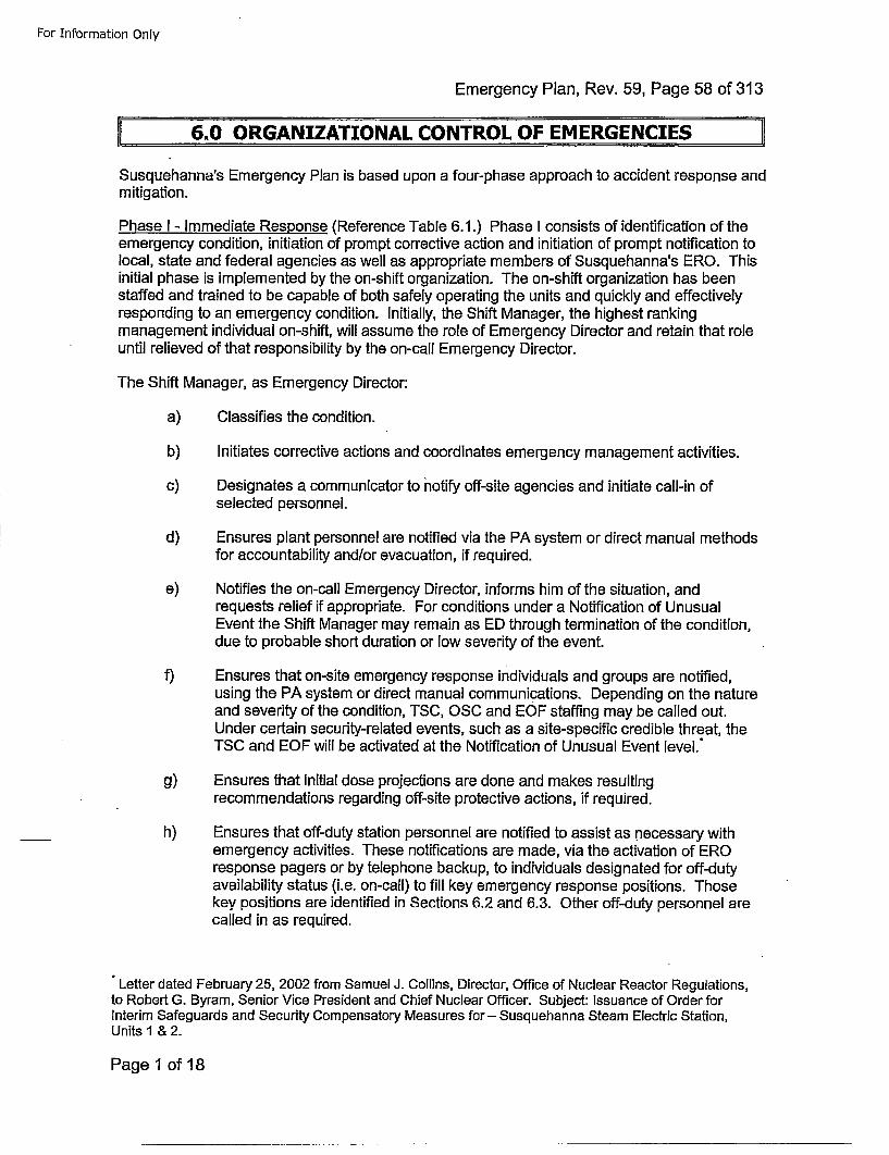
For Information Only
Emergency Plan, Rev. 59, Page 58 of 313
6.0 ORGANIZATIONAL CONTROL OF EMERGENCIES
Susquehanna's Emergency Plan is based upon a four-phase approach to accident response andmitigation.
Phase I - Immediate Response (Reference Table 6.1.) Phase I consists of identification of theemergency condition, initiation of prompt corrective action and initiation of prompt notification tolocal, state and federal agencies as well as appropriate members of Susquehanna's ERO. Thisinitial phase is implemented by the on-shift organization. The on-shift organization has beenstaffed and trained to be capable of both safely operating the units and quickly and effectivelyresponding to an emergency condition. Initially, the Shift Manager, the highest rankingmanagement individual on-shift, will assume the role of Emergency Director and retain that roleuntil relieved of that responsibility by the on-call Emergency Director.
The Shift Manager, as Emergency Director:
a) Classifies the condition.
b) Initiates corrective actions and coordinates emergency management activities.
c) Designates a communicator to notify off-site agencies and initiate call-in of
selected personnel.
d) Ensures plant personnel are notified via the PA system or direct manual methodsfor accountability and/or evacuation, if required.
e) Notifies the on-call Emergency Director, informs him of the situation, andrequests relief if appropriate. For conditions under a Notification of UnusualEvent the Shift Manager may remain as ED through termination of the condition,due to probable short duration or low severity of the event.
f) Ensures that on-site emergency response individuals and groups are notified,using the PA system or direct manual communications. Depending on the natureand severity of the condition, TSC, OSC and E0F staffing may be called out.Under certain security-related events, such as a site-specific credible threat, theTSC and EOF will be activated at the Notification of Unusual Event level."
g) Ensures that initial dose projections are done and makes resultingrecommendations regarding off-site protective actions, if required.
h) Ensures that off-duty station personnel are notified to assist as necessary withemergency activities. These notifications are made, via the activation of EROresponse pagers or by telephone backup, to individuals designated for off-dutyavailability status (i.e. on-call) to fill key emergency response positions. Thosekey positions are identified in Sections 6.2 and 6.3. Other off-duty personnel arecalled in as required.
"Letter dated February 25, 2002 from Samuel J. Collins, Director, Office of Nuclear Reactor Regulations,to Robert G. Byram, Senior Vice President and Chief Nuclear Officer. Subject: Issuance of Order forInterim Safeguards and Security Compensatory Measures for - Susquehanna Steam Electric Station,Units I & 2.
Page 1 ofl18
For Information Only
Emergency Plan, Rev. 59, Page 59 of 313
Upon activation of Phase II, additional personnel are available, and control of the emergencyand dissemination of in-plant teams shifts from the Control Room to the TSC.
Phase II - Activation of On-Site ERO - (Reference Table 6.1 and Figures 6.2 and 6.3.) Uponnotification by the on-shift organization, the on-call Emergency Director reports to thesite/Control Room to assume the role of Emergency Director. As specified in Figures 6.2 and6.3, the minimum number of support coordinators and staffs also report to the site. Theseindividuals form the nucleus of the ED's Team and activate the TSC and OSC. The TSC andOSC are fully functional within 60 minutes of event classification. As the on-call EmergencyDirector and his support coordinators arrive, they are briefed and assume responsibility for theirparticular areas of expertise. Emergency management activities, including communications, areunder the control of the Emergency Director; dose projection and assessment activities aredirected by the Radiation Protection Coordinator; technical expertise is directed by the TechSupport Coordinator; the Operations Coordinator oversees Operations activities; and theDamage Control Team Coordinator oversees in-plant damage control actions. The OSCCoordinator supports the operations and damage control team coordinators by managingpersonnel in the OSC (back up 0S0 in the event the OSC is not habitable). The TSC takesover all emergency management and support activities from the on-shift organization, freeingthem to devote their efforts towards establishing and maintaining the plant in a safe, stablecondition.
The onsite ERO may be further augmented as shown in Figures 6.2 and 6.3 by personnel fillingTSC positions and OSC positions not designated as minimum requirements. Figures 6.2 and6.3 also designate minimum requirements for the TSC and OSC respectively.
In the event of hazards preventing site access or certain security related events, personnel whonormally report to the Technical Support Center and Operations Support Center will report to theAlternate TSC and 0SC at the Emergency Operations Facility. OSC personnel can be sent to thesite to mitigate site damage as soon as the site is secured. The alternate TSC will be activated assoon as possible to support the site; however, it is recognized that the activation time for thealternate TSC may exceed 60 minutes.*
Phase Ill - Activation of Off-site ERO - (Reference Table 6.1 and Figure 6.4.) This organizationstaffs the Emergency Operations Facility to provide management of the overall emergencyresponse as well as technical support, off-site radiological assessment, and communications.
Staffing of the EOF occurs following an Alert, a Site Area Emergency, or a General Emergencydeclaration. The EOF is required to activate following a Site Area Emergency or GeneralEmergency classification and take over management of the emergency from the TSC or ControlRoom within 90 minutes of the Site Area Emergency or higher classification. Activation of theEmergency Operations Facility requires the minimum staff as identified in Figure 6.4. When theinitial emergency classification is a Site Area Emergency or higher, the EOF will take over themanagement of the emergency within 90 minutes of the declaration of a Site Area Emergency.Due to the site response during a daytime security event that starts at the SAE level, the EOFmay not be staffed within 90 minutes. With an event in progress, station personnel may bedirected to take cover and therefore be unable to respond to the EOF until cleared by plantsecurity. At the discretion of the Emergency Director, the EOF can be activated and take overmanagement of the emergency earlier.
"Letter dated February 25, 2002 from Samuel J. Collins, Director, Office of Nuclear Reactor Regulations,to Robert G. Byram, Senior Vice President and Chief Nuclear Officer. Subject: Issuance of Order forInterim Safeguards and Security Compensatory Measures for- Susquehanna Steam Electric Station,Units 1 & 2.
Page 2 of 18
For Information Only
Emergency Plan, Rev. 59, Page 60 of 313
Functional operation will include:
* Management of overall emergency response
• Coordination of radiological and environmental assessment
* Determination of recommended protective actions
* Communications
* Coordination of emergency response activities with Federal, State, local county andmunicipal agencies
The offsite ERO may be further augmented as denoted in Figure 6.4 by personnel filling EOFpositions not designated as minimum requirements. Figure 6.4 designates minimum staffing.
Phase IV - Restoration - This phase leads ultimately to the return to service of the unit. Theorganizational and philosophical concepts that are utilized during this phase are highlydependent upon the nature of the emergency. The restoration phase does not begin untilthere is complete assurance that the plant is in a stable shutdown condition and that there isno inadvertent or unplanned significant release of radioactivity to the environment.
6.1 NORMAL OPERATING ORGANIZATION
FSAR Section 13.1.2 defines the normal operating organization for SSES as illustratedin FSAR Figure 13.1-3: Minimum shift response during off-hours is as follows:
1 Shift Manager (SRO)
1 Unit Supervisor (SRO)
3 Plant Control Operators (RO)
4 Non-Licensed Operators
1 Shift Technical Advisor
2 Health Physics Technicians
1 Chemistry Technician
1 Emergency Plan Communicator
1 NRC Communicator
Fire Brigade response personnel per Technical Requirements Manual
Security Personnel as specified in the SSES Security Plan
Page 3 of 1 8
For Information Only
Emergency Plan, Rev. 59, Page 61 of 313
NOTE: On-shift staffing may be less than the minimum Emergency Plan requirementfor a period of time not to exceed 2 hours in order to accommodate unexpectedunavailability of on-duty shift individuals provided immediate action is taken torestore shift complement to within minimum requirements. This note applies topersonnel who are on-duty, not oncoming shift relief.
6.2 ON-SITE EMERGENCY ORGANIZATION-(PHASE II)
Technical Specification 5.2, FSAR Section 13.1, and FSAR Section 17.2 definequalification requirements for Susquehanna Nuclear, LLC personnel. Departmentimplementing procedures define specific qualification and training requirements forSusquehanna ERO positions.
6.2.1 Emeraencv Director
The Shift Manager assumes the role of Emergency Director (ED) until heis relieved by a qualified Emergency Director or a qualified RecoveryManager (RM).
Non-delegable duties (duties the ED cannot delegate except to anotherqualified ED or RM) are duties related to classification of emergencies,decision to notify state and local agencies, and Protective ActionRecommendations.
The ED assumes full responsibility for the implementation andadministration of the Emergency Plan and is responsible for assuringcontinuity of resources until those responsibilities are turned over to theRecovery Manager. The responsibility and authority of the ED are setforth in Appendix E of this plan.
The ED cannot relinquish any responsibilities until the arrival of andassumption of responsibilities by the Recovery Manager at the EOF. Atthat time, the ED may relinquish any responsibilities except those relatedto maintaining the Unit in a safe shutdown condition with adequate corecooling and no uncontrolled radioactive material refleases.
If the Emergency Director cannot perform this function during theemergency, he will be succeeded by the Operations Coordinator untilanother qualified Emergency Director arrives to 'assume thisresponsibility.
Functional responsibilities of the ED include:
a. Immediately upon notification of an existing or potentialemergency, report to the Control Room and initiate assessmentactivities, including classification of the emergency and doseprojections if appropriate.
b. Manage overall implementation of the immediate on-sitecorrective and protective actions to bring the incident undercontrol and mitigate its effects.
Page 4 of 18
For Information Only
Emergency Plan, Rev. 59, Page 62 of 313
c. Assure that appropriate notifications of emergency classificationand protective action recommendations to state and localagencies are made within 15 minutes of declaration of an EAL.
d. Assure that appropriate notifications and recommendations to theNRC are made immediately after notification to state and localagencies, but not later than one hour after declaration of anemergency classification.
e. Augment the on-site ERO with duty roster personnel and otheravailable station staff members as dictated by the emergencycondition.
f. Continue reassessment of emergency status and makeappropriate recommendations including protective actions tooff-site organizations.
g. Ensure that information released is accurate and released throughthe proper channels.
h. Activate Emergency Facilities described in Section 8.0, asrequired.
i. Assign a technical liaison to the state EOC when requested.
j. Communicate with and provide information to the RecoveryManager and the Public Information Manager.
k. Authorize issuance of Radioprotective Drugs in accordance withprescribed procedures. This should include consultation with theRadiation Protection Coordinator and medical consultants.
I. Authorize Emergency dose extensions. This should includeconsultation with the Radiation Protection Coordinator.
m. Authorize taking essential corrective action that may involve therisk of emergency radiation exposure to ERO personnel. Table7.2 provides the basic criteria for this decision.
n. Implement RCA and site evacuations as required.
o. _Re~quest Federal assistance to augment ERO capabilities asnecessary. Such requests should be coordinated with PEMAand/or DEP/BRP and are normally done through the RecoveryManager and the EOF staff.
6.2.2 Operations Coordinator
Responsibilities:
a. Prepare the TSC for activation if the TSC ED has relieved theControl Room ED of responsibility.
Page 5 of 18
For Information Only
Emergency Plan, Rev. 59, Page 63 of 313
b. Advise the Shift Manager in directing the Control Room andin-plant operational activities.
c, Direct activities of the Damage Control Team Coordinator, SAMCoordinator, and TSC Communicator.
d. Advise the ED on plant operations and conditions.
e. Establish and set priorities for mitigation with the concurrence ofthe ED.
6.2.3 TSC Communicator
Responsibilities:
a. Make proper notification to off-site organizations.
b. Initiate call-in procedures as requested by the ED.
c. Function as liaison for emergency-related communicationsbetween the ED and on-site and off-site emergency groups.
d. Maintain communications with the NRC.
e. Maintain records during the emergency.
6.2.4 Radiation Protection Coordinator
Responsibilities:
a. Ensures dose projections are performed until relieved by the EOF.
b. Provide radiological advice to the ED concerning on-site
emergency activities.
c. Provide protective action recommendations to the ED.
d. Maintain communication with and provide information to the EOFDose Assessment Supervisor.
e. Maintain communication with and provide radiological informationto DEP/BRP until relieved by the EOF.
f. Provide on-site radiation monitoring personnel for effluent releaseassessment.
g. Provide radiation monitoring personnel for emergency teamefforts.
h. Direct personnel and area contamination control anddecontamination activities.
i. Provide dose projections to the Dose Assessment Supervisor until
relieved of that responsibility by the EOF.
Page 6 of 18
For Information Only
Emergency Plan, Rev. 59, Page 64 of 313
j. Perform initial off-site environmental assessment until relieved bythe EOF.
k. Ensure radiological data is communicated to the NRC via theHealth Physics Network.
I. Advise the Emergency Director and organization on use of Ki andemergency dose extensions.
6.2.5 Technical Support Coordinator
Responsibilities:
a. Analyze mechanical, electrical, and instrument and controlproblems; determine alternate solutions, design and coordinatethe installation of short-term modifications.
b. Analyze thermo hydraulic and thermodynamic problems anddevelop solutions.
c. Assist in the development of procedures necessary for conductingemergency operations and damage control.
d. Analyze conditions and develop guidance for the ED andoperations personnel.
e. Resolve questions concerning Operating License requirementswith NRC representatives.
f. Maintain lead technical responsibility, coordinate technicalinformation with the EOF as appropriate, and request technicalsupport from the EOF or other engineering/technical resources.
g. Maintain communication with and provide technical information toDEP/BRP Technical, as required, until relieved by the EOF.
h. Provide core damage estimates.
i. Until relieved, provide direction to Chemistry Technician toperform emergency plan actions.
6.2.6 Security Coordinator
Responsibilities:
a. Maintain plant security and institute appropriate contingencymeasures.
b. Account for personnel as directed by EP-PS procedures.
c. Act as liaison with outside groups in providing additional resourcessuch as manpower, equipment, supplies, and transportation.
Page 7 of 18
For Information Only
Emergency Plan, Rev. 59, Page 65 of 313
d. Coordinate provisions for transportation, food, and other logisticalsupport for emergency personnel.
e. Provide personnel and work schedules for relieving emergencypersonnel.
6.2.7 OSC Coordinator
Responsibilities:
a. Report to the OSC.
b. Organize, brief, dispatch, and direct, as necessary, the onsitedamage control teams.
c. Coordinate the availability and assignment of personnelsupporting activities for the ED and other ERO managers.
d. Organize and manage emergency response personnel in the OSC.
6.2.8 Damaaqe Control Team Coordinator
Responsibilities:
a. Participate in briefings with the TSC ED and helping to setpriorities.
b. Ensure damage control resources are allocated on the correctpriorities by providing priorities to the OSC Coordinator andmonitoring INDIA Team assignments.
c. Communicate with Operations Coordinator, the Technical SupportCoordinator, and the OSC Coordinator.
6.2.9 Radio Communicator
Responsibilities:
a. Maintain radio communications with all in-plant teams.
b. Maintain an up-to-date status of in-plant radiological conditions.
6.2.10 Severe Accident Managqement (SAM) Coordinator
Responsibilities:
a. Make recommendations to the Operations Coordinator formitigation of the effects of a severe accident at SSES.
6.2.11 HP Specialist
Responsibilities:
a. Determine radiological conditions in the plant.
Page 8 of 18
For Information Only
Emergency Plan, Rev. 59, Page 66 of 313
b. Assess on-site habitability.
c. Provide guidance and brief teams on radiological and ALARA
considerations.
d. Monitor in-plant team exposures.
6.2.12 Non-Op~erations Support Personnel
Maintenance Technicians, Chemistry Technicians, and HP trainedpersonnel are called out per Table 6.1 to support damage control,chemistry, and radiological functions. Table 6.1 designates personnelwho report in 60 minutes and 90 minutes.
6.2.13 Engineering Staff (Core Thermal Hydraulic Engineer. Electrical Engqineer,Mechanical Engineer)
Responsibilities
a. Provide core damage estimates. (Core Thermal Hydraulic
Engineer)
b. Analyze mechanical problems and other discipline related issuesand determine solutions and provide support for implementation ofrequired mechanical actions. (Mechanical Engineer)
c. Analyze electrical and instrumentation and control problems andother discipline related issues. Determine alternate solutions andprovide support for implementation of required electrical/l&Cactions. (Electrical Engineer)
All responders are notified to provide for full augmentation of resources atthe TSC and OSC for the positions in Figures 6.2 and 6.3. Theaugmented response may be greater than 60 minutes and may occurafter the TSC has activated.
6.3 OFF-SITE RESOURCES AND ACTIVITIES (PHASE Il1)
Technical Specification 5.3, FSAR Section 13.1, and ESAR Section 17.2 define thequalification requirements for Susquehanna Nuclear, LLC personnel. Departmentimplementing procedures define specific qualification and training requirements forSusquehanna ERO positions.
Notification of the Recovery Manager is made via notification of key managers for theNotification of Unusual Event and via ERO activation for higher levels by theCommunic~ators in the Control Room or TSC. An on-call duty roster is available in theSusquehanna Information Management System.
At the discretion of the Emergency Director, the EOF can be manned or activated at aNotification of Unusual Event level.
Page 9 of 18
For Information Only
Emergency Plan, Rev. 59, Page 67 of 313
Staffing of the EOF occurs following an Alert, a Site Area Emergency, or a GeneralEmergency declaration. The EOF is required to activate following a Site Area Emergencyor General Emergency classification for the purpose of taking over management of theemergency from the TSC or Control Room within 90 minutes of the Site Area Emergencyor higher classification.
When these responders are briefed on the emergency situation and verify thatnecessary equipment is functioning properly, the Recovery Manager will assumeresponsibility for overall management of the emergency response. The followingfunctions are provided:
* Management of overall emergency response
* Coordination of radiological and environmental assessment* Determination of recommended protective actions
* Communications
* Coordination of emergency response activities with Federal, State, local countyand municipal agencies.
All responders are notified to provide for full augmentation of resources at the EOF forthe positions in Figure 6.4. The augmented response may be greater than ninetyminutes and may occur after the EOF has activated.
6.3.1 EOF Ornqanization
6.3.1.1 Recovery Manacqer
if the Recovery Manager cannot perform this function during theemergency, he will be succeeded by the Engineering SupportSupervisor until another qualified Recovery Manager arrives.
Non-delegable duties (duties the RM cannot delegate except toanother qualified ED or RM) are duties related to classificationof emergencies, decision to notify state and local agencies, andProtective Action Recommendations.
Responsibilities:
a. Upon activation of the EOF, initiate assessmentactivities, including classification of the emergency anddose projections if appropriate.
b. Provide continuous coordination and evaluation ofSusquehanna activities during an emergency having orpotentially having environmental consequences.
c. Manage overall Susquehanna emergency response andassuring continuity of resources.
d. Act as lead interface with off-site government agencyofficials.
Page 10 of 18
For Information Only
Emergency Plan, Rev. 59, Page 68 of 313
e. Assure appropriate notifications and recommendationsto offsite organizations are timely.
f. Continue reassessment of emergency status and makeappropriate recommendations including protectiveactions to off-site organizations.
g. Ensure that information released is accurate and madethrough proper channels.
h. Direct the activities of all other EOF managers.
i. Request Federal assistance to augment EROcapabilities as necessary. Such requests should becoordinated with PEMA and/or DEP/BRP.
j. Notify PEMA Emergency Operations Center ofProtective Action Recommendations.
k. When requested, send a representative to the StateEOC. If conditions result in implementation of theFederal Radiological Emergency Response Plan, assigna representative to the Federal Response Center, to theFederal Radiological Monitoring and AssessmentCenter, and to the Joint Information Center (most likelythe PIM).
I. Authorize issuance of Radioprotective Drugs inaccordance with prescribed procedures. This shouldinclude consultation with the Dose AssessmentSupervisor and medical consultants.
6.3.1.2 Engineeringq Support Sup~ervisor
Responsibilities:
a. Manage engineering support resources in the EOF.
b. Provide technical support to aid in decision making
process.
c. Keep BRP informed concerning technical status of theplant and any mitigating actions being considered or inprogress.
d. Provide technical information concerning plant statusand mitigating actions to the off-site agencies.
Page 11 of 18
For Information Only
Emergency Plan, Rev. 59, Page 69 of 313
6.3.1.3 EOF Support Supervisor
Responsibilities:
a. Provide support to the Recovery Manager in review ofplant data.
b. Oversee formal communications leaving the EOF.
c. Oversee proper facility set up.
d. Provide administrative support.
e. Support the Recovery Manager withl off-site agencyinterface.
6.3.1.4 Dose Assessment Supervisor
Responsibilities:
a. Ensure dose projections are performed.
b. Evaluate the magnitude and effects of actual or potentialradioactive releases from the plant.
c. Recommend appropriate off-site protective measures to
the Recovery Manager.
d. Recommend appropriate emergency classifications tothe Recovery Manager.
e. Communicate with the Radiation Protection Coordinator
in the TSC and with DEP/BRP radiological personnel.
f. Control field monitoring teams.
g. Perform off-site environmental assessment.
6.3.1.5 EOF Communicator
Responsibilities:
a. Assume responsibility from the TSC for off-sitenotifications (except ENS communications).
b. Transmit information about the emergency to off-siteorganizations.
c. Function as liaison for questions received from otherorganizations.
d. Maintain a record of emergency notifications.
Page 12 of 18
For Information Only
Emergency Plan, Rev. 59, Page 70 of 313
6.3.1.6 Radiologqical Support Staff (Dose Assessment Staffer. FieldTeam Director, Radiologqical Monitoring Team)
Responsibilities:
a. Perform dose calculations, as required. (DoseAssessment Staffer)
b. Monitor and control field teams. (Field Team Director)
c. Perform monitoring of areas around the plant asdirected. (Radiological Monitoring Team)
6.3.2 Joint Information Center
The ED ensures that the JIC (Figure 6.4) is promptly notified andprovided with available details of the emergency. The JIC staff providesinformation regarding the emergency and items of public interest tomunicipal groups, initiates appropriate news releases, and responds toquestions from the media officials. After the Recovery Manager assumescontrol of the EOF, the Public Information Manager reports to theRecovery Manager.
6.3.2.1 Public Information Managqer
Responsibilities:
a. Serve as official company spokesperson.
b. Prepare and disseminate SSES information to the publicvia the news media.
c. Interpret plant status information for the news media andother agencies.
d. Arrange for news media conferences.
e. Manage rumor control.
f. Establish interfaces and coordinates news releases withthe federal and state agencies in the JIC.
6.3.3 Local Off-Site Support Services
The Emergency Director, and the Recovery Manager as appropriate,ensures that appropriate off-site emergency support groups are contactedto provide the type and level of assistance that m~iy be necessary to dealwith the existing emergency condition. Organizations that may becontacted for assistance during an emergency condition at SSES arelisted in Appendix A, Letters of Agreement. Methods available forcontacting these support groups include direct telephone communicationswith individual organizations, use of the 911 telephone system foremergency services, and message relay through LCEMA or CCEMA.
Page 13 of 18
For- Information Only
Emergency Plan, Rev. 59, Page 71 of 313
6.3.4 Off-Site Support Services
An emergency at SSES may require additional technical services andequipment. This type of assistance may be obtained from theorganizations listed in Table 6.2 and Appendix A.
6.4 COORDINATION WITH PARTICIPATING GOVERNMENT AGENCIES
The ED and the RM ensure that off-site authorities are notified and apprised ofemergency events at SSES when their respective facilities are managing theemergency.
Notification of a NOUE (Notification of Unusual Event) is primarily to ensure that theauthorities are cognizant of the details of events that may arouse public concern and initiateinquiries by news media or members of the public.
6.4.1 County Agqencies
LCEMA and CCEMA provide for:
* Planning and coordination with municipal, State, and Federal
authorities.
* Initial response to notification by SSES.
* Alert and warning of local populations within the 10 mile EPZ..
* Evacuation and other protective measures for local populationswithin the 10 mile EPZ.
* Emergency services.
* Situation analysis.
• Operation of county EOC.
LCEMA and CCEMA also provide direction for the local organizations that are assignedaction or support responsibilities under their plans.
The primary method of notification to LCEMA and CCEMA is via the Centrex TelephoneNetwork (CTN). Secondary methods are radio and regular telephone.
6.4.2 State Agencies
PEMA provides for:
* Issuance of planning guidance.
* Coordination of State response to nuclear incidents.
* Coordination of multi-county Emergency Response Planning.
* Operation of PEMA EOC.
Page 14 of 18
For Information Only
Emergency Plan, Rev. 59, Page 72 of 313
* Provision for emergency public information.
* Coordination of State agencies and departments.
DEP/BRP provides for:
* Technical consultation on Radiological and Plant conditions.
• Accident assessment.
* Recommendations for protective actions.
* Recommendations for protection of potable water and food.
* Recommendations for recovery and re-entry (off-site).
* Operation of DEP/BRP EOC.
initially, SSES notifies PEMA, who, in turn, notifies DEPIBRP. DEPIBRP calls back toSSES to obtain radiological and plant condition information and establish acommunication link with SSES. If the emergency warrants, DEP/BRP responds to theEOF.
The primary method of notification to PEMA is via the Centrex Telephone Network(CTN). CTN communications between SSES and DEP/BRP are used for transmittingradiological and technical information/recommendations.
6.4.3 Federal Agqencies
As detailed in the Federal Radiological Emergency Response Plan(FRERP), the Federal government maintains extensive capabilities toassist states and licensees in responding to radiological emergencies.The ED and, upon EOF activation, the RM are authorized to requestFederal assistance. Such requests should be coordinated with PEMAand/or DEPIBRP.
NC- designated Lead Federal Agency (LFA) under the NationalResponse Plan (NRP).
The primary method of notification to the NRC is via the EmergencyNotification System (ENS). Upon notification of an emergencyclassification, the NRC will enter one of several response modes basedon the severity of the event. Response modes include:
Normal (Increased Regional Monitoring)MonitoringActivationExpanded Activation
Page 15 of 18
For Information Only
Emergency Plan, Rev. 59, Page 73 of 313
In the Normal and Monitoring modes, NRC site presence is provided bythe Resident Inspectors who typically observe activity in the ControlRoom and TSC. Upon Activation, a site team will be dispatched that canarrive at the site within several hours. Response assignments areprimarily at the EOF, with a few individuals located at the JIC, TSC,Control Room and OSC. If conditions warrant, the NRC can go toExpanded Activation that has a much larger response to staff shift typeoperations and additional team support personnel.
DOE - provides radiological monitoring and assessment assistance.
The primary method of notification to DOE is by telephone, althoughassistance is typically requested through the Lead Federal Agency (NRC)or through the State (DEP/BRP). Initial DOE response is by aRadiological Assistance Program (RAP) team dispatched from the DOEBrookhaven Area Office. This team can arrive within eight hours andwould operate primarily out of the EOF.
If the situation necessitates additional technical assistance, DOE can setup and staff a Federal Radiological Monitoring and Assessment Center(FRMAC) in the vicinity of SSES. A FRMAC, which draws DOEresources and personnel from its Nevada Operations Office, can beoperational within about 24 hours. The location of such a center would beselected based on actual radiological deposition patterns. The FederalFRMAC team is initially managed by DOE, with personnel also providedby NRC, EPA, USDA, HHS, and other agencies. The State andSusquehanna would assign personnel to the FRMAC to coordinatemonitoring activity.
DHS - FEMA - responsible for coordinating all Non-technical Federalresponse.
If the emergency situation has warranted implementation of the NationalResponse Plan (NRP), DHS-FEMA will set up and staff a FederalResponse Center in the vicinity of SSES. The location of such a centerwould be selected based on current needs and conditions. Access to allFederal non-technical assistance is through the Federal Response Centerwhere representatives of participating agencies are based.
Other Federal Acqencies
In addition to NRC, DOE, and DHS-FEMA, other Federal agencies areavailable to provide assistance under the National Response Plan (NRP).The extent of participation depends on the nature and magnitude of theevent. A full listing of these agencies and description of their missions isfound in the National Response Plan (NRP).
Additional information on available resources can be found inN UREG-14421 FEMA-REP-17, "Post-Emaergency Response ResourcesGuide."
Page 16 of 18
For Information Only
Emergency Plan, Rev. 59, Page 74 of 313
Joint Information Center (JIC)
The National Response Plan (NRP) provides for each participatingagency to be represented at a Joint Information Center, along with theState and the facility licensee. For Susquehanna SES, it is expected thatthese parties will agree to utilize Susquehanna's JIC to fulfill thison-scene Joint Information Center role.
Resources Available to Support Federal Response
A. Lodging and Food Service - Lodging and food service forpersonnel operating from the FRMAC, Federal Response Center,and JIC are available from local commercial resources in theWilkes-Barre, Hazleton, and Bloomsburg areas.
B. Communications - Capability provided by DOE and DHS-FEMA,supplemented by standard telephone service to be establishedwhen facilities are selected, are adequate for the FRMAC andFederal Response Center.
C. Security - Security arrangements for the FRMAC and FederalResponse Center can be made by the DOE and DHS-FEMA,respectively, with local resources.
0. Transportation - Federal response personnel will provide their owntransportation by renting commercially available vehicles.
E. Airport - Wilkes-Barre/Scranton International Airport, Avoca,Pennsylvania.
6.5 RESTORATION
The Susquehanna ERO continues to provide appropriate emergency response functionsuntil such time as the emergency has been terminated or the Talen CorporateLeadership Council (CLO) has approved the implementation of a long-range restorationorganization. Termination from an emergency condition is through joint evaluation bythe organizations involved. In the case of a severe emergency involving off-siteconsequences, this would include the Recovery Manager, DEP/BRP, and NRC. TheSenior Vice President and Chief Nuclear Officer requests that the Talen CorporateLeadership Council establish a restoration organization when the following guidelineshave been met:
* In-plant systems are stable, adequate core cooling established and contingencysystems and plans available.
*In-plant radiation levels are stable or are decreasing with time.
* Releases of radioactive material to the environment are under control or haveceased.
* Any fire, flooding or similar emergency conditions are under control or have ceased.
Page 17 of 18
For Information Only
Emergency Plan, Rev. 59, Page 75 of 313
Although planning for restoration varies according to the emergency, a long-term restorationorganization that is general in nature has been defined. The restoration organization is aproject-type organization with their major activities conducted from the EOF. Thisorganization is depicted in Figure 6.6 and major responsibilities are defined below.
* Restoration Manaqer - A designated officer or senior manager from Susquehanna tomanage SSES restoration operations.
* Plant Operations Managqer - A designated manager from Susquehanna qualified tocontrol plant operations including security.
* Technical Support Manaaer - A designated manager from Susquehanna qualified tomanage a technical group.
* Radiological Manager - A designated manager qualified to manage the radioactivewaste and radiological control aspects.
* Maintenance Managqer - A designated manager qualified to coordinate the activitiesof Susquehanna, NSSS supplier, and construction forces on proposed plantmodifications or other construction support.
* Advisory Support Function - Advisory support consists of senior representatives ofthe NSSS supplier, the NRC, and special consultants.
* Scheduling/Planningq Managqer - A designated manager to coordinate plans andschedules for the Restoration Manager.
* Administration and Logqistics Manager - A designated manager who is responsible forproviding administrative, logistic, communications and personnel support.
* Public Information Manager - A designated manager qualified to manage publicrelations activities.
During restoration operations, the radiation exposure limits of 10OCFR20 apply.Compliance with those limits is the responsibility of the Restoration Manager via theapplicable Health Physics organization.
At the time of declaring that an emergency has entered the restoration phase, theRestoration Manager is responsible for providing notification to all applicable agencies.
Restoration actions that plan for, or may result in, radioactive release are evaluated bythe Restoration Manager as far in advance of the event as is possible. Such events anddata are reported to the appropriate off-site emergency response organizations andagencies prior to initiating release.
Page 18 of 18
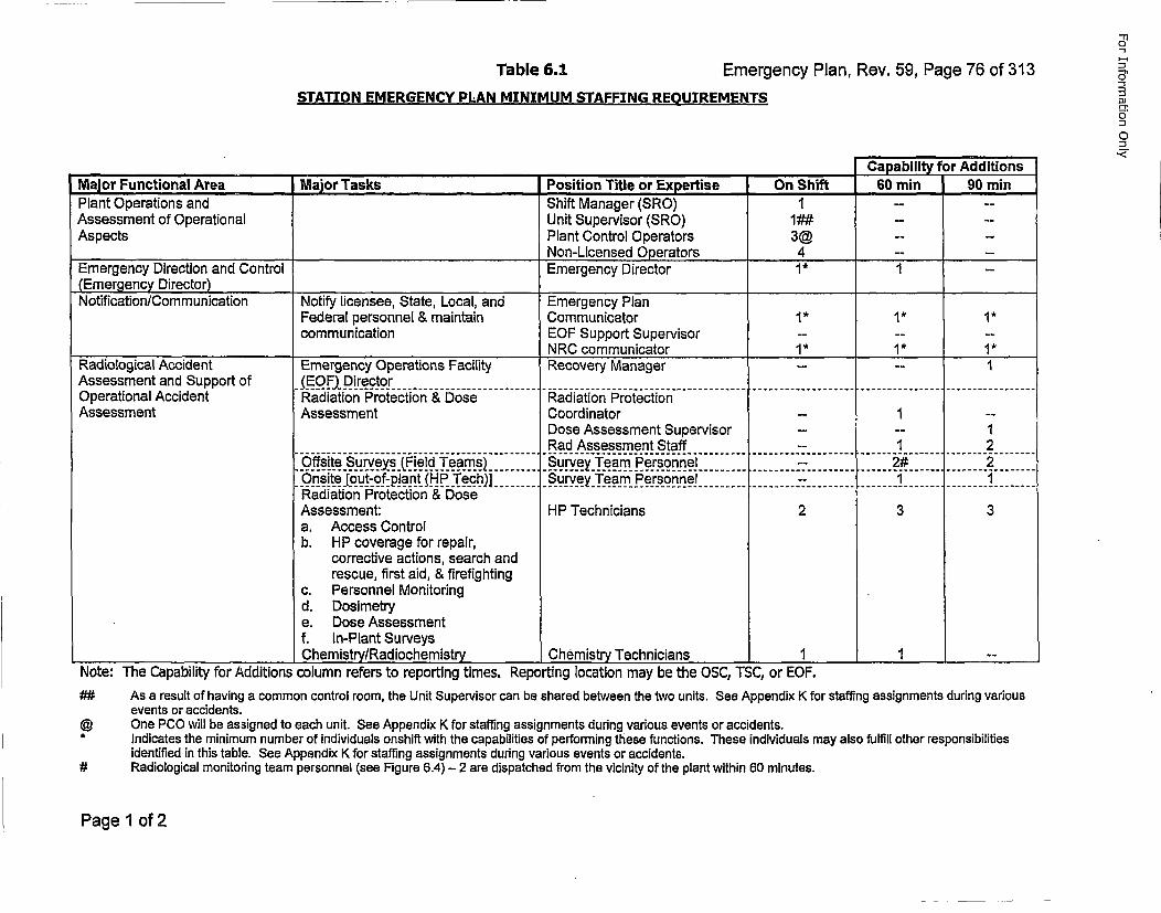
Table 6.1 Tabl 6.1Emergency Plan, Rev. 59, Page 76 of 313
STATION EMERGENCY PLAN MINIMUM STAFFING REOUIREMENTS
Caoability for AdditionsMajor Functional Area Major Tasks Position Title or Expertise On Shift 60 rai 90 raiPlant Operations and Shift Manager (SRO) 1 ....-Assessment of Operational Unit Supervisor (SRO) 1## ...Aspects Plant Control Operators 3@ ....-
Non-Licensed Operators 4 ....-Emergency Direction and Control Emergency Director 1* 1 --
(Emergency Director)______________Notification/Communication Notify licensee, State, Local, and Emergency Plan
Federal personnel & maintain Communicator 1" 1" 1*communication EOF Support Supervisor ......-
NRC communicator 1" 1* 1"Radiological Accident Emergency Operations Facility Recovery Manager - -- IA ssessm ent up o t andE___.)D Support................ ...........of.........................irector...........Operational Accident Radiation Protection & Dose Radiation ProtectionAssessment Assessment Coordinator -- 1 --
Dose Assessment Supervisor ....- 1Rad Assessment Staff -- 1 2
• Ofsite.S.urveyXs.(Field._Tea~m~s)..... .Su.rveyT~eam__Pe~r~so~n~n~el......... -: ........ 2-....... 2....On it ou -__~fp!_ant_. ._P _._~.. ] ...... S~ur. ey.Te.am- .P.e~rso nn.e ......... _-.- ...... ... I........ .....
Radiation Protection & DoseAssessment: HP Technicians 2 3 3a. Access Controlb. HP coverage for repair,
corrective actions, search andrescue: first aid, & firefighting
c. Personnel Monitoringd. Dosimetrye. Dose Assessmentf. In-Plant Surveys
________________Chemistry/Radiochemistry Chemistr Technicians I 1 --_____
Note: The Capability for Additions column refers to reporting times. Reporting location may be the OSC, TSC, or EOF.## As a result of having a common control room, the Unit Supervisor can be shared between the two units. See Appendix K for staffing assignments during various
events or accidents.@ One PCO will be assigned to each unit. See Appendix K for staffing assignments during various events or accidents.* Indicates the minimum number of individuals onshift with the capabilities of performing these functions. These individuals may also fulfill other responsibilities
identified in this table. See Appendix K for staffing assignments during various events or accidents.# Radiological monitoring team personnel (see Figure 6.4) - 2 are dispatched from the vicinity of the plant within 60 minutes.
Page 1 of 2
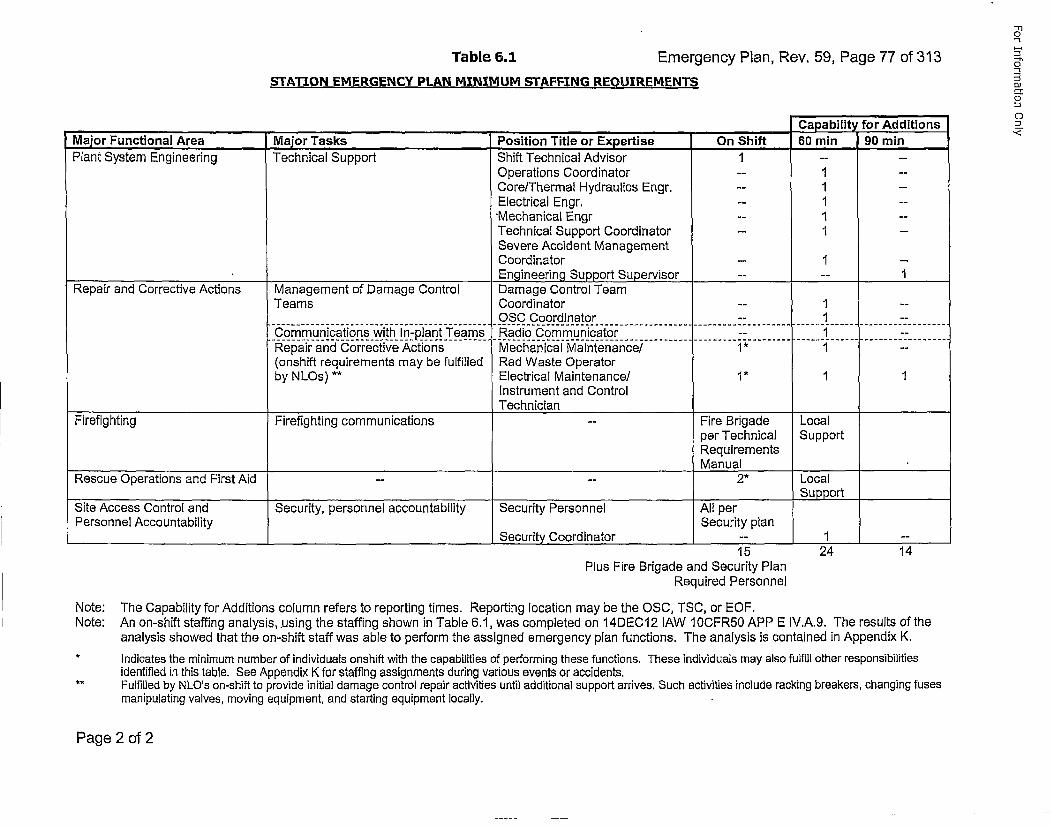
Table 6.1 Tabl 6.1Emergency Plan, Rev. 59, Page 77 of 313STATION EMERGENCY PLAN MINIMUM STAFFING REQUIREMENTS
Ca~abilitv for Additions
Major Functional Area Maior Tasks ,Position Title or Expertise On Shift 60 min 90 minPlant System Engineering Technical Support Shift Technical Advisor 1 ....-Operations Coordinator -- I --
Core/Thermal Hydraulics Engr. -- 1 --
Electrical Engr. -- I --
"Mechanical Engr -- 1 --Technical Support Coordinator -- I --
Severe Accident ManagementCoordinator -- I --
Engineering Support Supervisor ....- 1Repair and Corrective Actions Management of Damage Control Damage Control Team
Teams Coordinator -- I --OSC Coordinator -- I --
Communications with In-plant Teams Radio Communicator -- I1-Repair and Corrective Actions Mechanical Maintenancef 1* 1 --
(onshift requirements may be fulfilled Rad Waste Operatorby NLOs) ** Electrical Maintenance! 1*" 1
Instrument and ControlTechnician
Firefighting Firefighting communications -- Fire Brigade Localper Technical SupportRequirementsManual
Rescue Operations and First Aid ---- 2* Local_______________________Support
Site Access Control and Security, personnel accountability Security Personnel All perPersonnel Accountability Security plan
Security _Coordinator -- t --
15Plus Fire Brigade and Security Plan
Required Personnel
24 14
Note: The Capability for Additions column refers to reporting times. Reporting location may be the OSC, TSC, or EOF.Note: An on-shift staffing analysis, .using the staffing shown in Table 6.1, was completed on 14DEC12 lAW I0CFR50 APP E IV.A.9. The results of theanalysis showed that the on-shift staff was able to perform the assigned emergency plan functions. The analysis is contained in Appendix K.
* Indicates the minimum number of individuals onshift with the capabilities of performing these functions. These individuals may also fulfill other responsibilitiesidentified in this table. See Appendix K for staffing assignments during various events or accidents.Fulfilled by NLO's on-shift to provide initial damage control repair activities until additional support arrives. Such activities include racking breakers, changing fusesmanipulating valves, moving equipment, and starting equipment locally.
Page 2 of 2
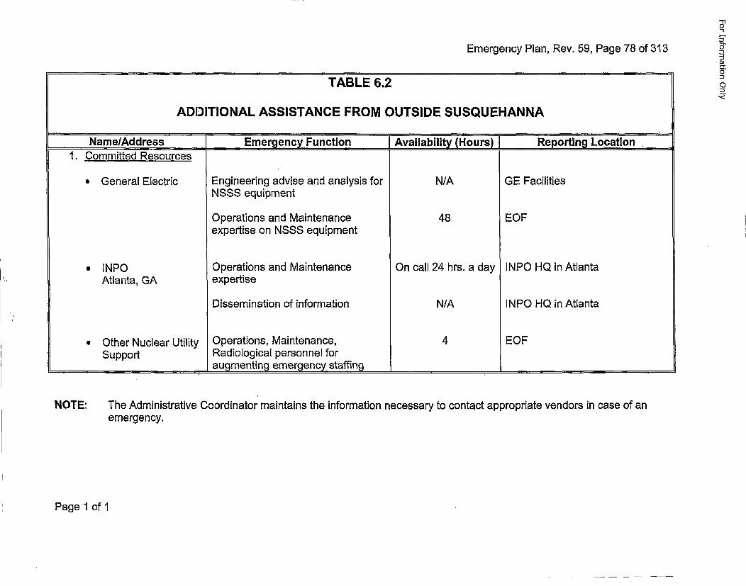
Emergency Plan, Rev. 59, Page 78 of 313DJ
0,
0TABLE 6.2
ADDITIONAL ASSISTANCE FROM OUTSIDE SUSQUEHANNA
Name/Address.. Emergency Function (Availability (Hours)] Reporting Location1. Committed Resources
*General Electric Engineering advise and analysis for N/A GE FacilitiesNSSS equipment
Operations and Maintenance 48 EOFexpertise on NSSS equipment
*INPO Operations and Maintenance On call 24 hrs. a day INPO HQ in AtlantaAtlanta, GA expertise
Dissemination of information N/A I NPO HQ in Atlanta
*Other Nuclear Utility Operations, Maintenance, 4 EOFSupport Radiological personnel for
_____________________augmenting emergency staffing ______________
NOTE: The Administrative Coordinator maintains the information necessary to contact appropriate vendors in case of anemergency.
Page 1 of I
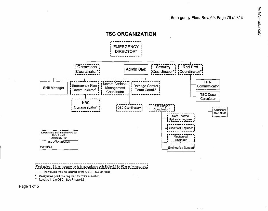
Emergency Plan, Rev. 59, Page 79 of 313
-1
:3JO4
"J
TSC ORGANIZATION
IIEMERGENCY
,DIRECTOR* !
U.-OperationsCoordinatori
-------
Admin Staff Secrit , Rad Prot,:Coordinator*l : Coordinator*I
Shit ange :Emergency Plan:
Shif Manger Communicator*
-- I
S NRC
!Communicator*
Susquehanna Steam Electric Station
Units 1 and 2Emergency Plan
TSC ORGANIZATION
IFIGURE 6.2
..... J------.......--......,Severe Accident: Damae.CotroManag...ement,,uaae nto
.C~oordi~nat~or..: Team Coord.*:
OSC.IR Coonrdinator** Tech Support In
Electrical Engineer:
... En.gineer. .
Engineering Support
a......................................................................... mm mImmm111,Dsnte minimum requirements in accordance with Table 6.1I for 60-minute response.:
-...Individuals may be located in the OSO, TSC, or Field.* Designates positions required for TSO activation.** Located in the OS0. See Figure 6.3
Page 1 of 5
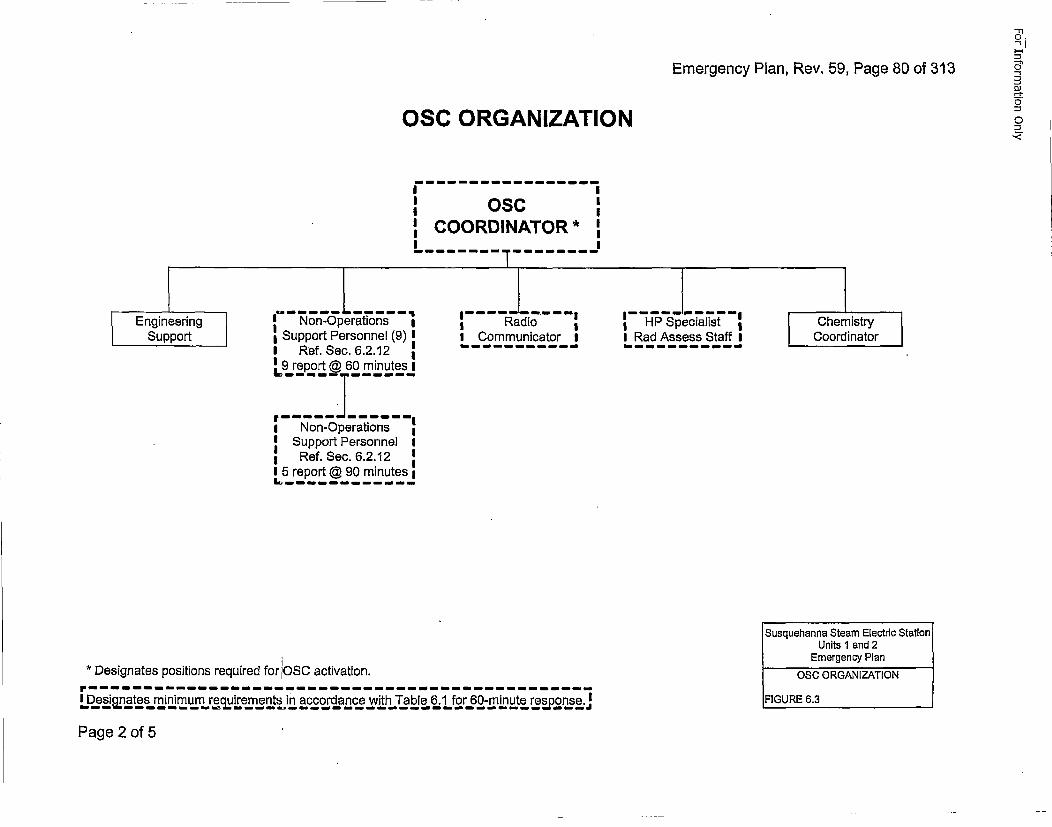
Emergency Plan, Rev. 59, Page 80 of 313
OSC ORGANIZATION
I IosoI: COORDINATOR* I
_________________________________----------------- -I
S Engineering
Support
I -Non-Operations I•IISupport Personnel (9) I
I Ref. Sec. 6.2.12 IL9 report @ 60 minutes I
* Non-Operations
ISupport Personnel III Ref. Sec. 6.2.12I 5 report @ 90 minutesL .......-- I
* Communicator I
I-----------I
IHP Specialist *I Rad Assess Staff I
S ChemistryCoordinator
* Designates positions required for OSC activation.
L esgnte mnimum recjuirements in accordance with Table 6.1 for 60-minute response I
Susquehanna Steam Electric StationS Units 1 and 2
Emergency Plan
O SCRG NIZTO
IFIGURE 6.3
Page 2 of 5
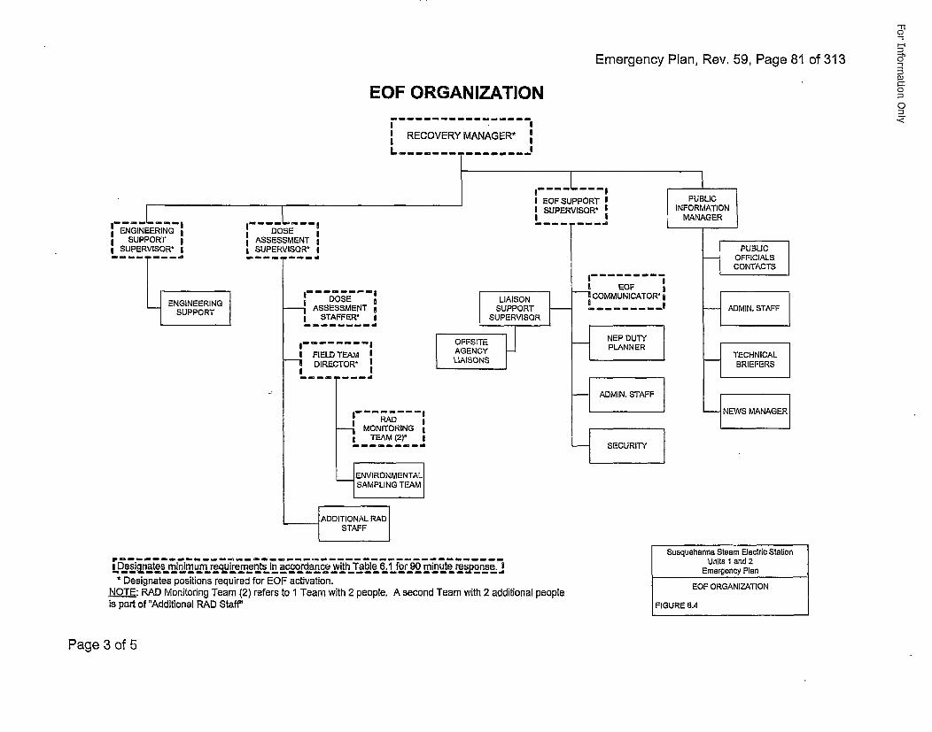
Emergency Plan, Rev. 59, Page 81 of 313
EOF ORGANIZATION
I II RECOVERY MANAGER* II IL-------- .....
------------------------------
III SUPPORT I
I SUPERVISOR' I
ENGINEERINGSSUPPORT -~ASSESSMENT I
L S.TAFFER;_I
R AD !'1MONITORING
TEAM (2)*
.ENVIRONMENTALSAMPLING TEAM
fL e~•nj srin m rrq ie et in accordance with Table 6.1 for 90 minute response. I* Designates positions required for EQF activation.
NOTE: RAD Monitoring Team (2) refers to 1 Team with 2 people. A second Team with 2 additional peopleis part of "Additional RAD Staff"
Page 3 of 5
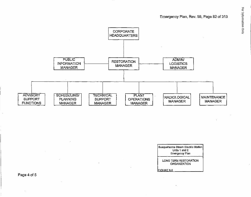
Emergency Plan, Rev. 59, Page 82 of 313
Susquehanna Steam Electric StationUnits 1 and 2Emergency Plan
LONG TERM RESTORATION
ORGANIZATION
FIGURE 6.6
Page 4 of 5
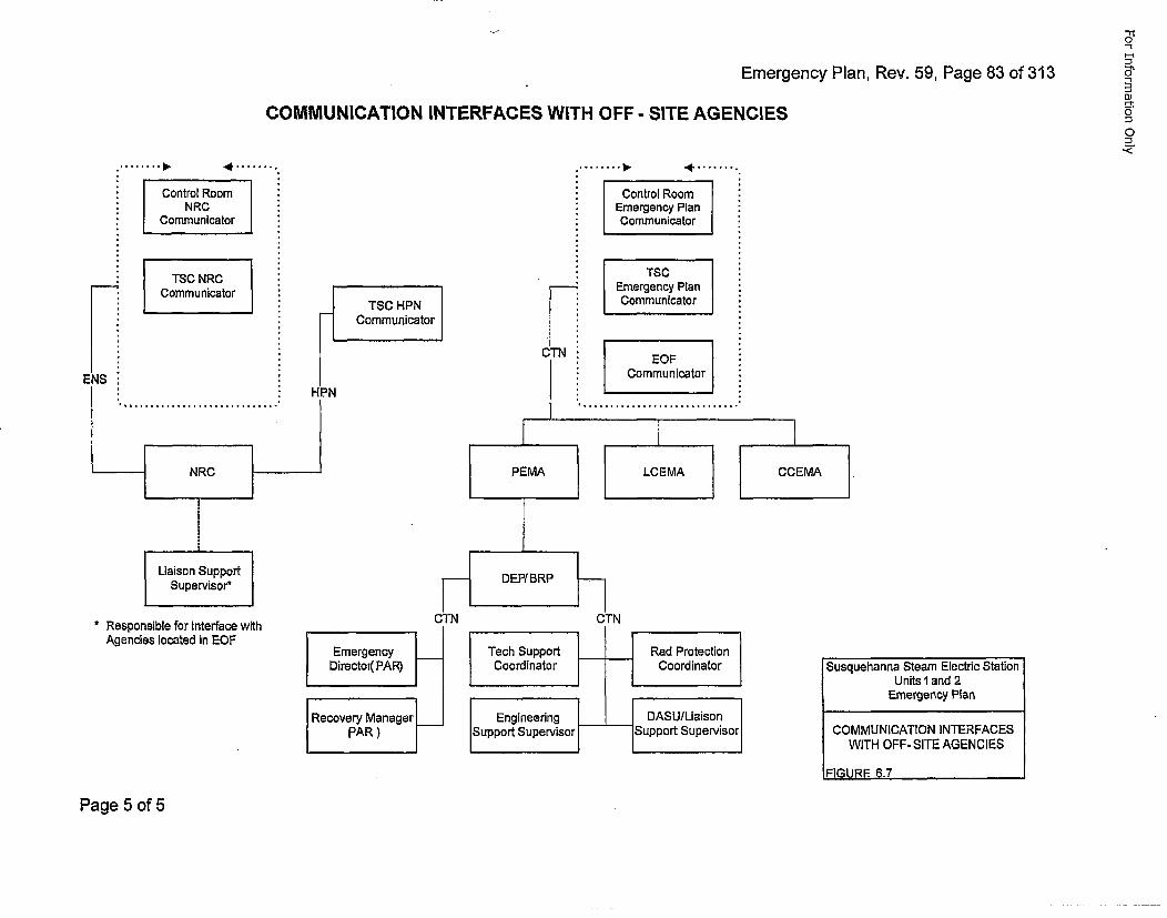
Emergency Plan, Rev. 59, Page 83 of 313
COMMUNICATION INTERFACES WITH OFF - SITE AGENCIESDJ
0
o
SControl RocNRC
Communica
STSC NRCCommunica
*.Control Room
EegnyPlanCommunca t or.
EegcyPlan
Lommnica t or.
Commnicator
* Responsible for Interface withAgencies located in EOF
I Tech Support t• Rad Protection
Coordinator Coordinator
Engineering DASU/Liaison
Support Supervisor -- Support Supervisor
Susquehanna Steam Electric StationUnits l and 2
Emergency Plan
COMMUNICATION INTERFACES
WITH OFF- SITE AGENCIES
FI(lIJRF= 6 7
Page 5 of 5
For Information Only
Emergency Plan, Rev. 59, Page 84 of 313
7Q MERENC .ESURSI•".~
"7.1 ASSESSMENT ACTIONS FOR ALL EMERGENCY CLASSIFICATIONS
Provisions are made for assessment through the course of an emergency to ensureeffective coordination, direction and upgrading of emergency activities in a timelymanner. The assessment actions are described in detail in Emergency Plan PositionSpecific Instructions (EP-PSs),
Continuous assessment of the status of plant systems and radiological conditions isprovided by plant instrumentation and is supplemented by routine surveillance functions.The occurrence of an Unusual Event is recognized by instrument alarms or indications,surveillance results, or other observation of an off-normal condition by an individual atthe station.
Assessment actions are described below. For a Notification of Unusual Event, one ormore of the actions listed below will be initiated; for higher emergency classifications,actions are continued, intensified, and increased in frequency.
Table 7.1 provides a Summary of Notification & Response Actions outlined in Section 7.1.
* Perform surveillance of in-plant instrumentation.
* Initial and continued observation of off-normal conditions.
* Obtain assistance from off-duty personnel and/or off-site support groups.
* Perform dose calculation activities. Correlate with field team data.
*Deploy field radiological monitoring teams to perform direct radiation measurementsand air sampling.
*Perform sampling and analysis of environmental media.
* Deploy on-site damage control teams.
• Perform reactor coolant sampling and analysis.
7.1.1 Off-Site Dose Calculations
T~he Emergency Director is responsible for initiating off-site dosecalculation and assessment activities. These activities are performed byhealth physics trained personnel who report to the Technical SupportCenter (TSC) (or the Control Room for all initial entries into theEmergency Plan). Data from the vent effluent monitors and themeteorological towers serve as inputs for the off-site dose calculationmethods.
The ED is responsible for calling in personnel to the TSC to performoff-site dose assessment activities. The Radiation Protection Coordinatorreports to the TSC within 60 minutes of notification.
Page 1 of 9
For Information Only"
Emergency Plan, Rev. 59, Page 85 of 313
Field monitoring teams are directed to selected monitoring location(s) byeither the Radiation Protection Coordinator, Dose Assessment Supervisor,Dose Assessment Staffer, or Field Team Director via radio and/or phonecommunication. The results of the teams' surveys are used to updateprojected doses and dose calculational assumptions. In addition, anindependent Remote Monitoring System can be used, if desired, tosupplement the information obtained by field monitoring teams. ThisRemote Monitoring System uses fixed radiation detectors which are locatednear the site perimeter and mobile monitoring equipment to locate andassess elevated radiation levels. This system is not required, but can beused, if desired, to supplement the existing monitoring capabilities.Terminals for this system are located in both the TSC and EOF.
The initial field monitoring team(s) are staffed within 60 minutes.Additional team(s) are dispatched upon activation of the EOF.
Each radiological monitoring team is supplied with a survey meter and lowvolume air sampler. TLDs are located at 17 sites around the station toprovide early information on accumulated off-site doses. Two sets of TLDsare provided at each of these sites; one set for dose accumulation during theperiod of releases and one set maintained for the normal monitoring period orexchanged early at the Dose Assessment Supervisor's discretion to meetinformation needs.
The ED and Recovery Manager recommend appropriate protectiveactions to PEMA Operations Center, Harrisburg, based upon the resultsof the off-site dose assessment activities.
7.1.1.1 Meteorologqy
The SSES on-site meteorological measurement system is basedupon an on-site primary meteorological tower located to the eastsoutheast of the station. The primary tower providesmeasurements of wind speed, wind direction, and wind variabilityat its 10 and 60-meter levels, temperature differential' betweenthe 10 and 60-meter levels, and ambient temperature and dewpoint at the 10-meter level. Precipitation is measured at groundlevel. In case of primary tower failure, a 10-meter on-site backupmeteorological tower will provide measurements of wind speed,wind direction, and wind variability.
A permanent supplemental tower is installed in the river valleynear the station to provide additional meteorological data to moreaccurately model the effects of surrounding terrain onatmospheric dispersion and transport. The tower is locatedapproximately 3.6 miles SW of the station off Route 93 just eastof Nescopeck.
The tower measures wind speed, wind direction, and sigma thetaat the 33-foot level. The tower also measures temperature at aheight of approximately 6.6 feet. The meteorological datacollected from this tower is used only to support assessment andrestoration efforts in the event there is an accidental release ofradioactive material from SSES.
Page 2 of 9
For Information.Only
Emergency Plan, Rev. 59, Page 86 of 313
The meteorological systems are instrumented to providecontinuous data to the control room and the Plant IntegratedComputer System (PICSY) for utilization in the TSC and EOF.Data that enters PICSY is viewable through various displayformats and is also transmitted to the NRC via ERDS. Digitaldataloggers are present at all of the SSES meteorologicaltowers. All data is stored locally and is available for acquisitionby interrogation across telephone lines. Primary and backuptower strip chart recorders are located in the control room.
Site specific, meteorological information for emergency doseassessment purposes can be obtained by contacting either ameteorologist or the National Weather Service Station using thephone numbers provided in the SSES Emergency TelephoneDirectory.
7.1.1.2 Health Physics Considerations
In the event of an unplanned radioactive release from either thereactor building vents, the turbine building vents, or the standbygas treatment vent; continuous gross noble gas readings areavailable from the vent monitors. Each monitor is also equippedwith in-line iodine and particulate sampling capability. Thesein-line samples are periodically removed and analyzed in order toprovide iodine and particulate release rate information. Eventdeclarations are based on Noble Gas readings or iodine andparticulate sample results.
The following Health Physics considerations are taken into account:selection of the accident type to closely approximate the isotopicmix and average gamma energies of the release occurring,radioactive decay from time of reactor shutdown, plumedecay-in-transit and iodine and particulate depletion due toprecipitation.
7.1.1.3 Dose Calculations for Airborne Releases
A dose calculation model is used to make current, site specificestimates and predictions of atmospheric effluent transport anddiffusion during and immediately following an accidental airborneradioactivity release. The purpose of the prediction is to providean input to the assessment of the consequences of accidentalradioactive releases to the atmosphere and to aid in theimplementation of emergency response decisions.
Page 3 of 9
For Information Only
Emergency Plan, Rev. 59, Page 87 of 313
The dose calculation model used is a fast running,time-dependent, variable trajectory plume segment "B" modelwith the following capabilities:
NOTE: A class "B" model is a numerical model thatrepresents the actual spatial and temporalvariations of plume distribution.
* Computes atmospheric dispersion at the site basedon atmospheric stability as a function of sitespecific terrain conditions with 15-minute upgradesof source term and meteorological conditions.
* Provides estimates of deposition and relativeconcentration of radioactivity within the plumeexposure and ingestion EPZs for the duration ofthe release.
* Incorporated in the calculations is wet and drydeposition which enables dose estimates from threepathways - plume, ground shine, and ingestion.
The dose program complies with the "Manual of Protective ActionGuides and Protective Actions for Nuclear Incidents," (EPA-400),adopting the dose calculation methodology in ICRP #26/30. Theaccident dose assessments are based on the adult physiology perEPA 400, except for one case-that is, child thyroid dose conversionfactors are used in calculating thyroid CDE. However adultphysiology is used in calculating thyroid CDE for purposes ofevaluating the need for a sheltering only PAR and evaluatingcontrolled venting of containment. Calculations of TEDE are madeusing the (adult) dose factors provided in EPA-400. The followingcalculational options are available:
*TEDE (Tot~al Effective Dose Equivalent) integrated dosesconsisting of the sum of external doses from plume shine, 50year committed effective dose equivalent from inhalation(CEDE), and 4 day ground shine doses.
* EDE and CDE dose rates for field team management.
* Fifty year thyroid committed dose (CDE), from inhalation ofradioactive materials.
* Population dlose (person rem) out to 50 miles.
* Summary print of projected doses for each of four projection times.
* Integrated ground dose for projected times specified by the user.
Page 4 of 9
For Information Only
Emergency Plan, Rev. 59, Page 88 of 313
The dose calculation program is a standalone program runningon PCs located in the TSC and EOF.
7.1.1.4 Liquid Release Calculations
Estimates of downstream river water concentrations are made byemploying effluent sample analysis or discharge monitor data,discharge flow rates and river elevation readings. The riverelevation is used to estimate the travel time to the point of interest.The calculated degree of mixing, together with the dischargemonitor data and the discharge flow rates are used to calculatedownstream concentrations.
7.2 CORRECTIVE ACTIONS
Detailed operating procedures and plant procedures are utilized by the plant operatingpersonnel to assist them in recognizing emergency events and taking the correctiveactions necessary to place the plant in a safe condition. Table 6.1 shows personnelavailable to respond to an emergency. Additionally, EP-PSs describe subsequent andsupplemental corrective actions for the scope of potential situations within each of theemergency classifications. These procedures are designed to guide the actions of thepersonnel to correct or mitigate the condition as early and as near to the source of theproblem as feasible.
Some essential corrective actions may involve the risk of emergency exposure to EROpersonnel. Such actions could involve preventing the release of large quantities ofradioactive material, reducing damage to major equipment or lifesaving actions.Table 7.2 specifies the limits for emergency exposure and other relevant criteria to beconsidered. The ED is responsible for all corrective actions taken to mitigate theconsequences of the accident on-site.
7.3 PROTECTIVE ACTIONS
Protective actions are implemented to prevent or mitigate consequences to individualsduring or after a radiological incident. Protective action recommendations within theSSES Exclusion Area and Site Boundary are the responsibility of the ED, but mayinclude assistance by the EOF. Protective actions outside the Site Boundary areprimarily the responsibility of State and local emergency organizations, but may includecoordination of activities, dissemination of appropriate data, and recommendations bythe ED or Recovery Manager. Effective integration of SSES procedures andimplementation plans with State and local implementation plans ensure that all membersof the public, including those located on Susquehanna property but outside theemergencY plan boundary, will be notified of protective actions to be taken and that theactions can be implemented in a timely manner. Protective action recommendations areoutlined in Table 7.3.
7.3.1 On-Site Protective Actions
The primary protective measure for on-site personnel in an emergency isprompt evacuation from areas that may be affected by significantradiation, contamination, or airborne radioactivity.
Page 5 of 9
For Information Only
Emergency Plan, Rev. 59, Page 89 of 313
Respiratory protective equipment and clothing are provided at the plantand in the various emergency equipment kits for personnel who may berequired to perform emergency activities.
Control of in-plant contamination is in accordance with SSES HealthPhysics procedures. In the event of radioactive contamination outsidefenced security areas, but within the exclusion area, access to such areasis controlled by Susquehanna with assistance from the PSP.
7.3.1.1 Local Ar'ea Evacuation
This category refers to evacuation from one area to anotherarea within the same building. The initiation of a Local AreaEvacuation results from ARM or CAM alarm(s) sounding in thesame area within a building or from observed conditions suchas smoke or toxic gas, which may indicate a possiblehabitability problem. The initial response for individuals is toevacuate to an unaffected area of the building, notify the plantControl Room of the conditions, and await further instruction.The ED assesses the situation, activates appropriateprocedures to rectify the condition and informs the personnelwhen to return to their respective work area via the PA systemor direct manual communication.
7.3.1.2 Radioloqically Controlled Area Evacuation
The initiation of a Radiologically Controlled Area Evacuationresults from ARM, CAM, or other applicable monitor alarms,(i.e., fire alarms). Notification for personnel to proceed with aRadiologically Controlled Area Evacuation is announced overthe plant PA system. If all or part of the PA system isunavailable then alternate manual methods may be used tonotify personnel of the need for evacuation and/oraccountability. The initial mandatory response by individuals isevacuation to an unaffected area. In this case, however, thenearest such area may not be in the same building, and multipleARM, CAM, or fire alarms are probable.
The decision to implement a Radiologically Controlled AreaEvacuation is the responsibility of the ED. Factors to beconsidered include the apparent levels of radiation and/orairborne radioactivity involved and the exposure to personnelthat would result from evacuating to Accountability Areas.
7.3.1.3 Security and Accountability
Accountability of on-site personnel during an emergency isaccomplished through the use of the physical security systemand station procedures. The physical security system clearlyestablishes who is within the protected area. Personnel arenotified to report to accountability areas during an emergencyvia an alert signal transmitted over the PA system. If all or partof the PA system is unavailable then alternate manual methodsmay be used to notify personnel of the need for evacuation
Page 6 of 9
For Information Only
Emergency Plan, Rev. 59, Page 90 of 313
and/or accountability. The names of the personnel reporting inare compared to those logged through the security system inorder to ensure total accountability.
If not completed earlier, accountability will be initiated immediatelyafter declaration of a Site Area Emergency and will be completedwithin 30 minutes of the declaration of a Site Area Emergency.
For certain security-related events, an evacuation of non-essentialpersonnel may be conducted prior to performing accountability.Security will collect badges upon egress from the site and thenperform accountability.
7.3.1.4 Site Evacuation
A Site Evacuation requires that all individuals on-site, except forControl Room operations personnel and others with specificemergency assignments, leave the site. lf the ED requiresoff-site assembly, personnel will go to the Remote AssemblyArea. The Primary Remote Assembly Area is the SusquehannaEnergy Information Center (NE Sector), as shown in Figure 8.1.The alternate Remote Assembly Area is the West Building(WSW Sector). Assembly area leaders will coordinateaccountability at Remote Assembly Areas.
Implementation of a Site Evacuation is the responsibilitY of theED. That decision is based on the severity of the incident, thelikelihood of escalation, and the radiation and airborneradioactivity levels throughout the station. Notification is madevia the PA system. If all or part of the PA system is unavailablethen alternate manual methods may be used to notify personnelof the need for evacuation and/or accountability.
Accountability is accomplished in passage through the securitygate. Personnel and vehicle contamination surveys are performedat the Remote Assembly Area, using portable survey instruments.
For certain events such as some security events, on-site personnelmay be directed to remain in place due to personal safety concernsuntil a more appropriate time for accountability and evacuation.Station procedures specify those security contingencies. *
•Letter dated February 25, 2002 from Samuel J. Collins, Director, Office of Nuclear Reactor Regulations, to RobertG3. Byram, Senior Vice President and Chief Nuclear Officer. Subject: Issuance of Order for Interim Safeguards andSecurity Compensatory Measures for - Susquehanna Steam Electric Station, Units i & 2.
Page 7 of 9
For Information Only
Emergency Plan, Rev. 59, Page 91 of 313
7.3.2 Off-Site Protective Actions
The responsibility for actions to protect off-site individuals rests with theCommonwealth of Pennsylvania.
DEPIBRP is responsible for evaluating information obtained from SSESand other sources and recommending appropriate off-site protectiveactions to PEMA. Such recommendations include:
* Shelter for affected populations* Evacuation of affected populations* Administration of thyroid prophylaxis* Control of contaminated agricultural products
The principal off-site local coordinating agency is LCEMA. Since the areaand population inside the ten-mile EPZ are partially within ColumbiaCounty, parallel emergency response functions are provided by CCEMA.Upon notification by PEMA of a situation that may require protectiveactions for off-site populations, LCEMA and CCEMA initiate appropriateactions. If PEMA has lost communication or is otherwise unavailable, it ispossible that the ED or Recovery Manager may contact LCEMA andCCEMA directly with protective action recommendations. If time permits,LCEMA and CCEMA obtain a review and verification by PEMA ofrecommendations made by the ED or Recovery Manager.
LCEMA and CCEMA protective actions include:
* Prompt alerting of the population within ten miles of the SSES throughthe use of the Alert Notification System (described in Section 8.0) andRoute Alerting Teams, a supplement to the siren system that isimplemented, as necessary, in the event of siren failure or to alertpersons or areas that may not be within the sound of the sirens.Route alerting is a municipal responsibility and is accomplished bymunicipal route alert teams travieling in vehicles along preplannedroutes delivering the following message: "There is an emergency atthe Susquehanna Steam Electric Station; please tune to yourEmergency Alert Station."
* Transmission of specific instructions to potentially affectedpopulations via the Emergency Alert System.
• Assistance for evacuation of the population within the ten-mile EPZ.
Appendix G includes the estimated times to evacuate all or segments ofthe population from the 1 0-mile EPZ, identifies potential problem areasand provides contingencies for dealing with adverse conditions. It wasutilized in the development of detailed evacuation plans by PEMA,LCEMA, and CCEMA.
Page 8 of 9
For Information Only
Emergency Plan, Rev. 59, Page 92 of 313
7.4 AID TO AFFECTED PERSONNEL
7.4.1 Emergqency Exposure
All reasonable measures are taken to maintain the radiation exposure ofemergency personnel who provide rescue, first aid, decontamination,ambulance, firefighting, law enforcement or medical treatment serviceswithin applicable limits specified in Table 7.2. "Guidance on Dose Limitsfor Workers Performing Emergency Services". Table 7.2 summarizes theemergency exposure criteria for entry or re-entry into areas for purposesof undertaking protective or corrective actions. Actions taken to providethe support activities listed above are considered commensurate with theactivities listed in Tale 7.2. Methods and conditions for permittingvolunteers to receive emergency radiation exposures are described inEP-PS procedures, and provide for expeditious decisions withconsideration to known and reasonable balance of associated risks.
7.4.2 Decontamination and First Aid
Personnel contamination in emergency situations is controlled to theextent feasible by the normal methods of using protective clothing andsurveying for contamination following the removal of such clothing.Personnel decontamination areas are available in-plant anddecontamination efforts involving significant amounts of contaminationare performed under the direction of Health Physics personnel.
At least two persons who are qualified in first aid methods are on-site atall times. First aid to injured personnel can be performed in conjunctionwith any necessary decontamination methods. However, if immediatetreatment of the injury is vital, that treatment takes precedence overdecontamination. This philosophy also extends to off-site emergencyassistance involving radioactive contamination. For that purpose,measures are established to ensure timely off-site medical treatment.
7.4.3 Medical Transportation and Treatment
Arrangements and agreements have been made for the transportationand treatment of patients from SSES, who may have injuries complicatedwith radioactive contamination or who may have been involved in aradiation incident.
Page 9 of 9
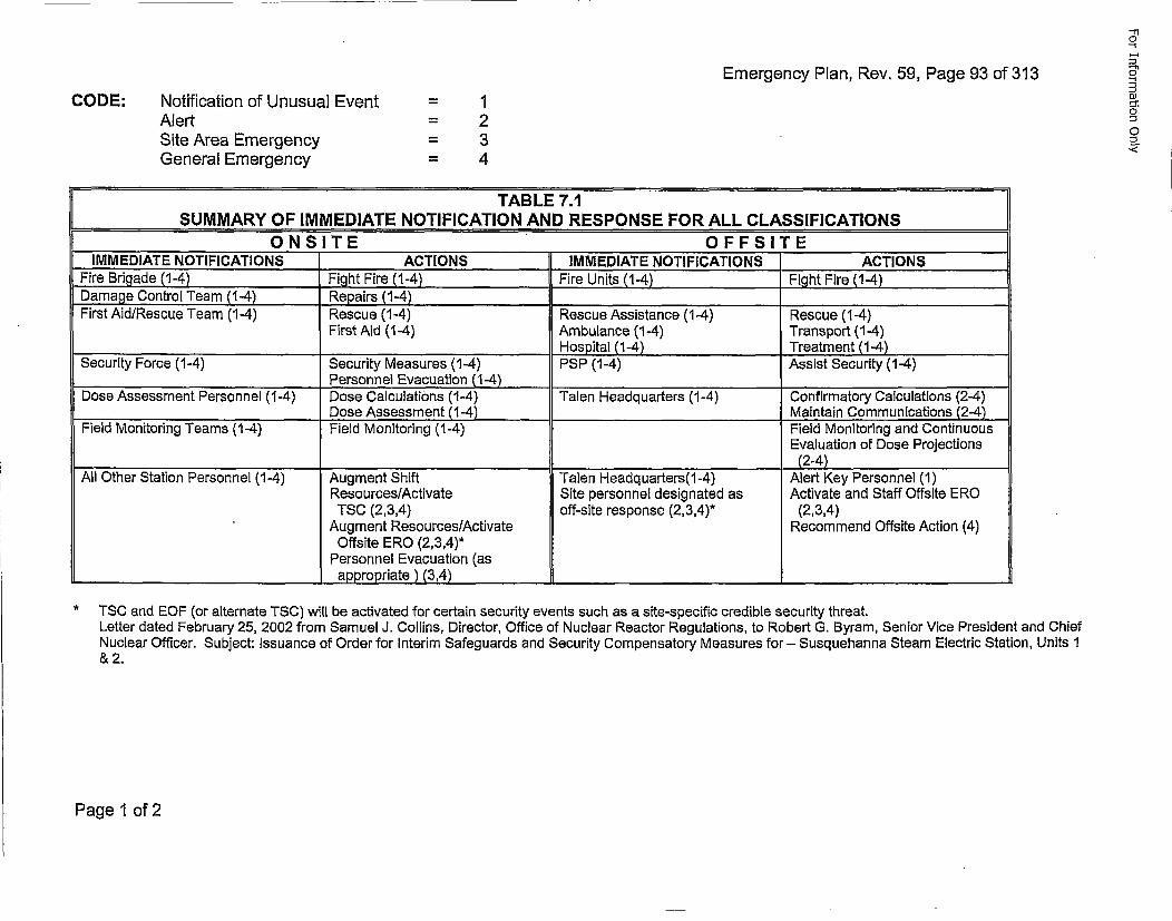
Emergency Plan, Rev. 59, Page 93 of 313
CODE: Notification of Unusual EventAlertSite Area EmergencyGeneral Emergency
= 1= 2= 3= 4
TABLE 7.1SUMMARY OF IMMEDIATE NOTIFICATION AND RESPONSE FOR ALL CLASSIFICATIONS
ONSITE OFFSITEIMMEDIATE NOTIFICATIONS ACTIONS IMMEDIATE NOTIFICATIONS 'ACTIONS
Fire Brigade (1-4) Figjht Fire (1-4) Fire Units (1-4) Fight Fire (1-4)Damage Control Team (1-4) Repairs (1-4)______________First Aid/Rescue Team (1-4) Rescue (1-4) Rescue Assistance (1-4) Rescue (1-4)
First Aid (1-4) Ambulance (1-4) Transport (1-4)____________________ ___________________Hospital (1-4) Treatment (1-4)
Security Force (1-4) Security Measures (1-4) PSP (1-4) Assist Security (1-4)__________________________Personnel Evacuation (1-4) ______________
Dose Assessment Personnel (1-4) Dose Calculations (1-4) Talen Headquarters (1-4) Confirmatory Calculations (2-4)__________________Dose Assessment (1-4) _______________ Maintain Communications (2-4)
Field Monitoring Teams (1-4) Field Monitoring (1-4) Field Monitoring and ContinuousEvaluation of Dose Projections
________________________(2-4)All Other Station Personnel (1-4) Augment Shift Talen Headquarters(1-4) Alert Key Personnel (1)
Resources/Activate Site personnel designated as Activate and Staff Offsite EROTSC (2,3,4) off-site response (2,3,4)* (2,3,4)
Augment Resources/Activate Recommend Offsite Action (4)Offsite ERO (2,3,4)*
Personnel Evacuation (asappropriate ) (3,4) ______________________________
*TSC and EOF (or alternate TSC) will be activated for certain security events such as a site-specific credible security threat.Letter dated February 25, 2002 from Samuel J. Collins, Director, Office of Nuclear Reactor Regulations, to Robert G. Byram, Senior Vice President and ChiefNuclear Officer. Subject: Issuance of Order for Interim Safeguards and Security Compensatory Measures for - Susquehanna Steam Electric Station, Units 1& 2.
Page 1 of 2
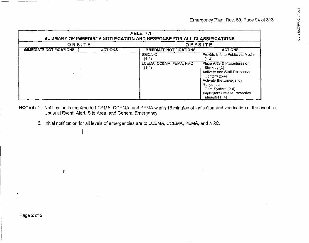
Emergency Plan, Rev. 59, Page 94 of 313
'TABLE 7.1SUMMARY OF IMMEDIATE NOTIFICATION AND RESPONSE FOR ALL CLASSIFICATIONS
ONS•TE OFFSITEIMMEDIATE NOTIFICATIONS ACTIONS IMMEDIATE NOTIFICATIONS ACTIONS
SEIC/JIC Provide Info to Public via Media(1-4) (1-4)
LCEMA, CCEMA, PEMA, NRC Place ANS & Procedures on(1-4) Standby (2)
Activate and Staff ResponseCenters (2-4)
Activate the EmergencyResponseData System (2-4)
Implement Off-site Protective_____________________________________________Measures (4)
NOTES: 1. Notification is required to LCEMA, CCEMA, and PEMA within 15 minutes of indication and verification of the event forUnusual Event, Alert, Site Area, and General Emergency.
2. Initial notification for all levels of emergencies are to LCEMA, CCEMA, PEMA, and NRC.
Page 2 of 2
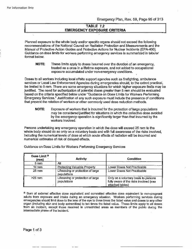
For Information Only
Emergency Plan, Rev. 59, Page 95 of 313
EMERGENCY EXPOSURE CRITERIA
Planned exposure to the whole body and/or specific organs should not exceed the followingrecommendations of the National Council on Radiation Protection and Measurements and theManual of Protective Action Guides and Protective Actions for Nuclear Incidents (EPA-400).Guidance on dose limits for workers performing emergency services is summarized in tabularformat below.
NOTE: These limits apply to doses incurred over the duration of an emergency,treated as a once in a lifetime exposure, and not added to occupationalexposure accumulated under non-emergency conditions.
Doses to all workers including local offsite support agencies such as firefighting, ambulanceservices or Local Law Enforcement Agencies during emergencies should, to the extent practical,be limited to 5 rem. There are some emergency situations for which higher exposure limits may bejustified. The need for authorization of potential doses greater than 5 rem should be evaluatedbased on the criteria specified below under "Guidance on Dose Limits for Workers PerformingEmergency Services." Justification of any such exposure must include the presence of conditionsthat prevent the rotation of workers or other commonly used dose reduction methods.
NOTE: Exposure of workers that is incurred for the protection of large populationsmay be considered justified for situations in which the collective dose avoidedby the emergency operation is significantly larger than that incurred by theworkers involved.
Persons undertaking any emergency operation in which the dose will exceed 25 rem to thewhole body should do so only on a voluntary basis and with full awareness of the risks involved,including the numerical levels of dose at which acute effects of radiation will be incurred andnumerical estimates of risk of delayed effects.
Guidance on Dose Limits for Workers Performing Emergency Services
Dose Limit a(rem) Activity Condition
5 rem All10 rem Protecting Valuable Property Lower Doses Not Practicable25 rem Lifesaving or protection of large Lower Doses Not Practicable
populations>25 remn Lifesaving or protection of large Only on a voluntary basis to persons
populations fully aware of the risks involved (see_______________ _______________________attached tables)
a Sum of external effective dose equivalent and committed effective dose equivalent to non-pregnantadults from exposure and intake during an emergency situation. Workers performing services duringemergencies should limit dose to the lens of the eye to three times the listed value and doses to any otherorgan (including skin and body extremities) to ten times the listed value. These limits apply to all dosesfrom an incident, except those received in unrestricted areas as members of the public during theintermediate phase of the incident.
Page 1 of 3
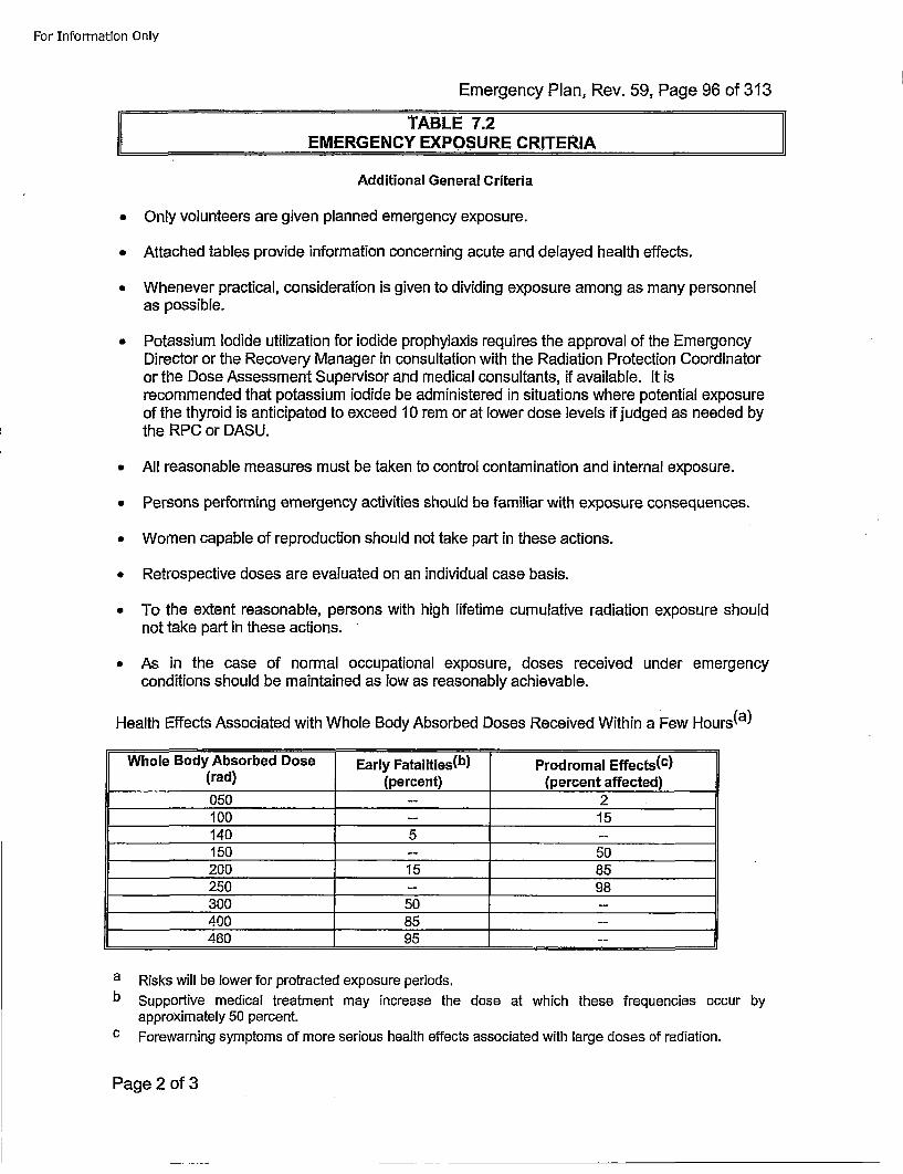
For Information Only
Emergency Plan, Rev. 59, Page 96 of 313
EMERGENCY EXPOSURE CRITERIA
Additional General Criteria
• Only volunteers are given planned emergency exposure.
* Attached tables provide information concerning acute and delayed health effects.
* Whenever practical, consideration is given to dividing exposure among as many personnelas possible.
• Potassium Iodide utilization for iodide prophylaxis requires the approval of the EmergencyDirector or the Recovery Manager in consultation with the Radiation Protection Coordinatoror the Dose Assessment Supervisor and medical consultants, if available. It isrecommended that potassium iodide be administered in situations where potential exposureof the thyroid is anticipated to exceed 10 remn or at lower dose levels if judged as needed bythe RPC or DASU.
* All reasonable measures must be taken to control contamination and internal exposure.
• Persons performing emergency activities should be familiar with exposure consequences.
* Women capable of reproduction should not take part in these actions.
* Retrospective doses are evaluated on an individual case basis.
• To the extent reasonable, persons with high lifetime cumulative radiation exposure shouldnot take part in these actions.
• As in the case of normal occupational exposure, doses received under emergencyconditions should be maintained as low as reasonably achievable.
Health Effects Associated with Whole Body Absorbed Doses Received Within a Few Hours(a)
Whole Body Absorbed Dose Early Fatalities(b) Prodromal Effects(c)(rad) ,(percent) (percent affected)
050 -- 2100 1 5140 5 --
150 -- 50200 15 85250 -- 98300 50 --
400 85 -
460 95 -
a Risks will be lower for protracted exposure periods.b Supportive medical treatment may increase the dose at which these frequencies occur by
approximately 50 percent.c Forewarning symptoms of more serious health effects associated with large doses of radiation.
Page 2 of 3
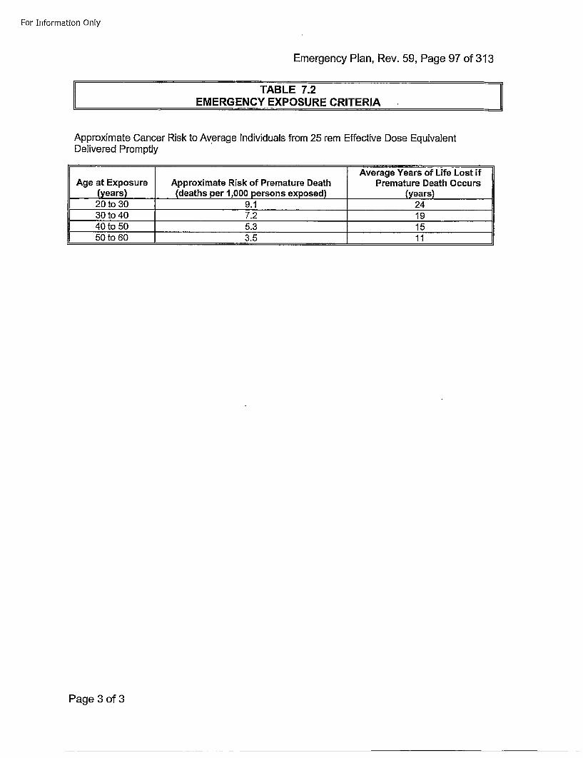
For Information Only
Emergency Plan, Rev. 59, Page 97 of 313
TABLE 7.2 •EMERGENCY EXPOSURE CRITERIA
Approximate Cancer Risk to Average Individuals from 25 rem Effective Dose EquivalentDelivered Promptly
Average Years of Life Lost ifAge at Exposure Approximate Risk of Premature Death Premature Death Occurs
(years) (deaths per 1,000 persons exposed) (years)20 to 30 9.1 2430 to 40 7.2 1940 to50 5.3 1550 to60 3.5 11
Page 3 of 3
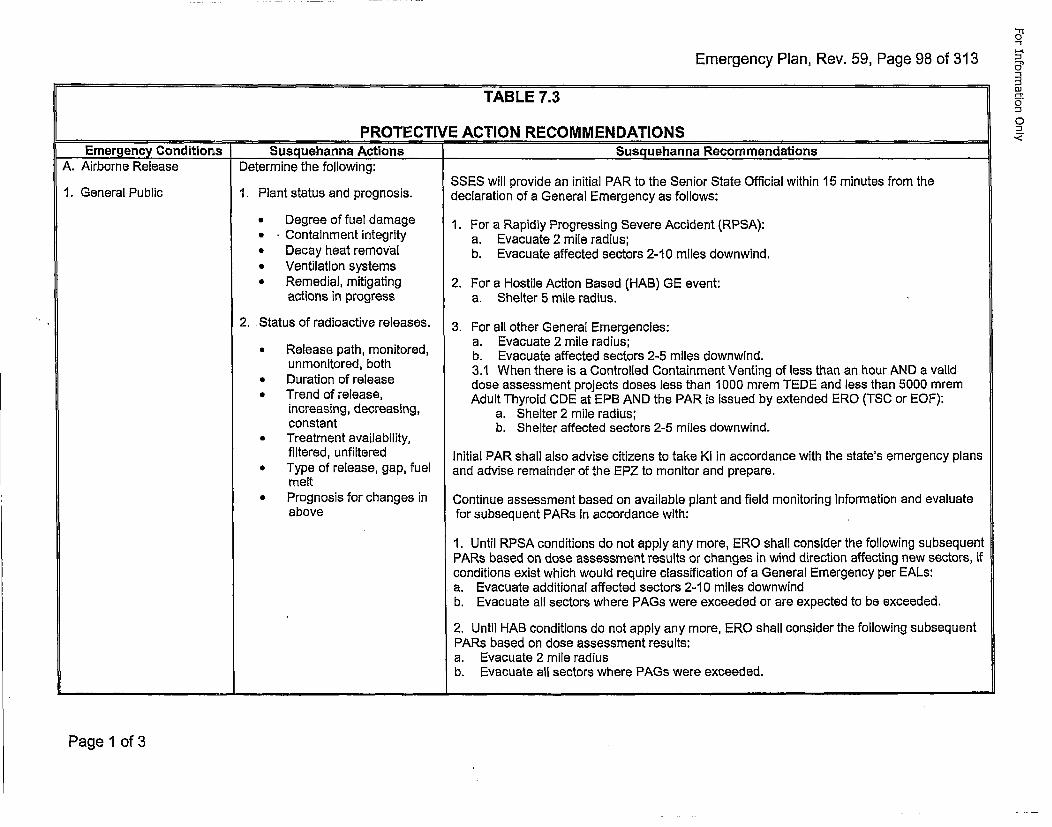
Emergency Plan, Rev. 59, Page 98 of 313
TABLE 7.3
S ~PROTECTIVE ACTION RECOMMENDATIONSEmergency Conditions r Susguehanna Actions Susguehanna Recommendations
-'1
03
0
A. Airborne Release Determine the following:
1. Plant status and prognosis.1. General Public
2.
* Degree of fuel damage* Containment integrity* Decay heat removal* Ventilation systems* Remedial, mitigating
actions in progress
Status of radioactive releases.
* Release path, monitored,unmonitored, both
• Duration of release* Trend of release,
increasing, decreasing,constant
* Treatment availability,filtered, unfiltered
* Type of release, gap, fuelmelt
* Prognosis for changes inabove
SSES will provide an initial PAR to the Senior State Official within 15 minutes from thedeclaration of a General Emergency as follows:
1. For a Rapidly Progressing Severe Accident (RPSA):a. Evacuate 2 mile radius;b. Evacuate affected sectors 2-10 miles downwind.
2. For a Hostile Action Based (HAB) GE event:a. Shelter 5 mile radius.
3. For all other General Emergencies:a. Evacuate 2 mile radius;b. Evacuate affected sectors 2-5 miles downwind.3.1 When there is a Controlled Containment Venting of less than an hour AND a validdose assessment projects doses less than 1000 mrem TEDE and less than 5000 mremAdult Thyroid CDE at EPB AND the PAR is issued by extended ERO (TSC or EOF):
a. Shelter 2 mile radius;b. Shelter affected sectors 2-5 miles downwind.
Initial PAR shall also advise citizens to take KI in accordance with the state's emergency plansand advise remainder of the EPZ to monitor and prepare.
Continue assessment based on available plant and field monitoring information and evaluatefor subsequent PARs in accordance with:
1. Until RPSA conditions do not apply any more, ERO shall consider the following subsequentPARs based on dose assessment results or changes in wind direction affecting new sectors, ifconditions exist which would require classification of a General Emergency per EALs:a. Evacuate additional affected sectors 2-10 miles downwindb. Evacuate all sectors where PAGs were exceeded or are expected to be exceeded.
2. Until HAB conditions do not apply any more, ERO shall consider the following subsequentPARs based on dose assessment results:a. Evacuate 2 mile radiusb. Evacuate all sectors where PAGs were exceeded.
Page 1 of 3
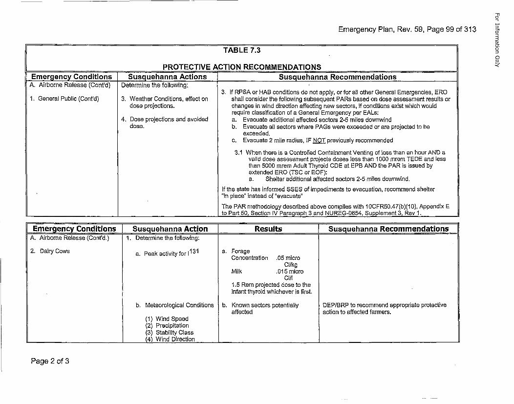
Emergency Plan, Rev. 59, Page 99 of 313
TABLE 7~3
0"
DiJ
0
01
PROTECTIVE ACTION RECOMMENDATIONSEmergency Conditions Susquehanna Actions Susguehanna Recommendations
A. Airborne Release (Cont'd) Determine the following:3. If RPSA or HAB conditions do not apply, or for all other General Emergencies, ERO
1. General Public (Cont'd) 3. Weather Conditions, effect on shall consider the following subsequent PARs based on dose assessment results ordose projections, changes in wind direction affecting new sectors, if conditions exist which would
require classification of a General Emergency per EALs:4. Dose projections and avoided a. Evacuate additional affected sectors 2-5 miles downwind
dose. b. Evacuate all sectors where PAGs were exceeded or are projected to beexceeded.
c. Evacuate 2 mile radius, IF NOT previously recommended
3.1 When there is a Controlled Containment Venting of less than an hour AND avalid dose assessment projects doses less than 1000 mrem TEDE and lessthan 5000 mrem Adult Thyroid CDE at EPB AND the PAR is issued byextended ERO (TSC or EOF):a. Shelter additional affected sectors 2-5 miles downwind.
If the state has informed SSES of impediments to evacuation, recommend shelter"in place" instead of "evacuate"
The PAR methodology described above complies with I OCFRb0.47(b)(1 0), Appendix E____ ___ ___ ____ ___ ___to Part 50, Section IV Paragraph 3 and NUREG-0654, Supplement 3, Rev 1.
Emergency Conditions ISusquehanna Action ]Results (Susquehanna RecommendationsA. Airborne Release (Cont'd.) 1. Determine the following:
2. Dairy Cows a. Peak activity for 1131 a. ForageConcentration .05 micro
CilkgMilk .015 micro
Ci/l1.5 Rem projected dose to theinfant thyroid whichever is first.
b. Meteorological Conditions b. Known sectors potentially DEP/BRP to recommend appropriate protectiveaffected action to affected farmers.
(1) Wind Speed(2) Precipitation(3) Stability Class
S(4) Wind Directi_ _
Page 2 of 3
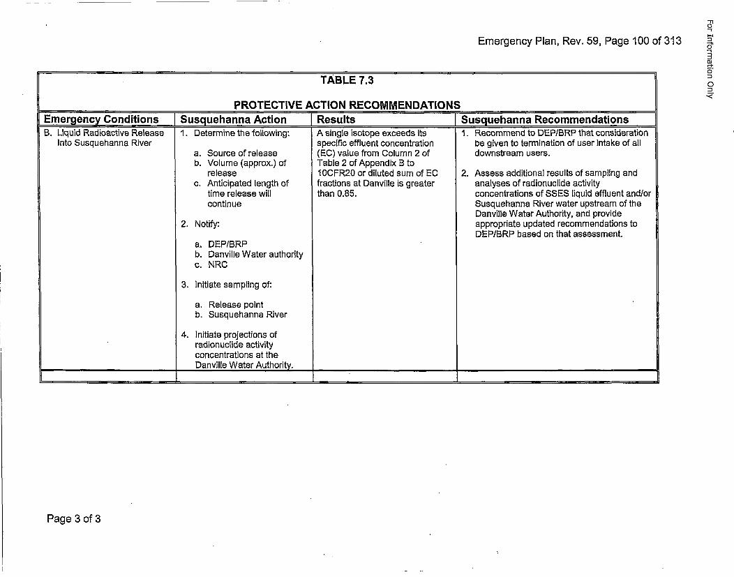
Emergency Plan, Rev. 59, Page 100 of 313
TABLE 7.3
_______________PROTECTIVE ACTION RECOMMENDATIONS[Emergency Conditions [Susqguehanna Action Results JSusguehanna RecommendationsB. Liquid Radioactive Release 1. Determine the following: A single isotope exceeds its 1. Recommend to DEPIBRP that consideration
Into Susquehanna River specific effluent concentration be given to termination of user intake of alla. Source of release (EC) value from Column 2 of downstream users.b. Volume (approx.) of Table 2 of Appendix B to
release 10CFR20 or diluted sum of EC 2. Assess additional results of sampling andc. Anticipated length of fractions at Danville is greater analyses of radionuclide activity
time release will than 0.85. concentrations of SSES liquid effluent and/orcontinue Susquehanna River water upstream of the
Danville Water Authority, and provide2. Notify: appropriate updated recommendations to
DEP/BRP based on that assessment.a. DEP/BRPb. Danville Water authorityc. NRC
3. Initiate sampling of:
a. Release pointb. Susquehanna River
4. Initiate projections ofradionuclide activityconcentrations at the
_________________________ DanvilleWaterAuthority. ______________________________________
Page 3 of 3
For Information Only
Emergency Plan, Rev. 59, Page 101 of 313
8.0 EMERGENCY FACILITIES AND E UiPMENT ]8.1 ON-SITE EMERGENCY CENTERS
8.1.1 Control Room
The Control Room is the primary location for the initial assessment andcoordination of corrective actions for all emergency conditions. TheControl Room is equipped with the display and controls for all critical plantsystems, radiological and meteorological monitoring systems, and allstation communication systems. Reference Appendix 0, Enclosure 7.
Off-site emergency functions initially served by the Control Room are transferredto the TSC or EOF for an Alert, a Site Area Emergency, or a General Emergencyas deemed appropriate by the ED. If the TSC and/or EOF are staffed, thefunctions may also be transferred at the Notification of Unusual Event level. Theprimary consideration is to ensure that the number of personnel involved with theemergency in the Control Room shall not impair the safe and orderly shutdown ofthe reactor or the operation of plant safety systems.
8.1.2 Operations Support Center
The OSC is the primary on-site assembly area for operations support teampersonnel during an emergency. There are 20OSC areas-a primary OSClocated separate from the TSC and Control Room and a backup 0S0 locatedin the Control Structure. The primary OSC is located on the first floor of theSouth (Administrative) Building. The backup OSC occupies 340 square feetadjacent to the Control Room on Elevation 729'-1" of the control structure.
The OSC is utilized initially' as the central location for assembly andaccountability of on-shift emergency team personnel required to perform suchfunctions as: firefighting, first aid, search and rescue, damage control, andon-site radiation monitoring. If and when the TSC is activated, allnon-operations support team personnel assemble and are accounted for inthe OSC (or TSC if the backup OSC is being utilized.) TSC personnel assessthe need for emergency team personnel and based on this assessment, theOSC dispatches available team personnel and call in additional personnel asneeded. The OSC and TSC assembly areas will be monitored continuouslyfor habitability. If these areas become uninhabitable, retained personnel willbe directed to alternate holding areas. Control and dispatch of these teams isthe responsibility of the Radio Communicator. The OSC Coordinatormanages operations and other support personnel.
Equipment required for these teams to perform their functions, as outlined inAppendix D is stored and maintained in the Control Room, Operations SupportCenter, Health Physics access control points and Maintenance tool areas.
Page 1 of 16
For Information Only
Emergency Plan, Rev. 59, Page 102 of 313
In the event of hazards preventing site access such as certain security events,personnel who normally report to the Operations Support Center will report tothe Alternate OSC at the Emergency Operations Facility. The alternate OSCwill be activated as soon as possible to support the site; however, it isrecognized that the activation time in the alternate OSC may exceed 60minutes. *
8.1.2.1 The Primary OSC
The primary 0S0 is located on the first floor of the South(Administration) Building. The 0S0 facilities may be used for normaldaily activities that do not degrade OSC emergency preparedness.
8.1.2.1.1 Habitability
8.1.2.1 .1 .a Allowable Post-Accident Radiation Doses
The primary OSC is monitored forradiation exposure using a local ARM andContinuous Air Monitor. The radiationdose will be limited to less than 5 RemTEDE, at which time the primary OSC willbe relocated to the backup OSC.Applicable criteria are specified inGeneral Design Criterion 19, StandardReview Plan NUREG 0800 Section 6.4,and NUREG-0737, Item lI.B.2.
8.1.2.1. .lb Postulated Post Accident Radiation Doses
The primary OSC is monitored forradiation exposure using a local ARM andContinuous Air Monitor. The radiationdose will be limited to less than 5 RemTEDE, at which time the OSC will berelocated to the backup 0SC. Applicablecriteria are specified in General DesignCriterion 19, Standard Review PlanNUREG 0800 Section 6.4, andNUREG-0737, Item ll.B.2.
8.1.2.1.1.c Radiation Monitoringq
A portable ARM will be installed in theprimary 05C area and a Continuous AirMonitor-Is installed in the South(Administration) Building cafeteria, whichis adjacent to the primary OSC. Thisarea serves as an accountability area anda holding area for essential personnel.
•Letter dated February 25, 2002 from Samuel J. Collins, Director, Office of Nuclear Reactor Regulations, toRobert G. Byram, Senior Vice President and Chief Nuclear Officer. Subject: Issuance of Order for InterimSafeguards and Security Compensatory Measures for - Susquehanna Steam Electric Station, Units I & 2.
Page 2 of 16
For Information Only
Emergency Plan, Rev. 59, Page 103 of 313
8.1.2.1.2 HVAC.
The primary OSC is subject to normal South(Administration) Building ventilation.
8.1.2.1.3 Shielding
There is no special shielding installed. The primaryOSC is located in an area with no outside walls.
8.1.2.1.4 Occupant Accommodations
Since the primary OSC is located in an administrationbuilding, toilet facilities and water are available.
8.1.2.1.5 Communications
The primary OSC communication system includes theplant PA system and telephone lines tied through theplant switchboard.
8.1.2.1 .5.a Telephone
The normal telephone service for theprimary OSC uses the plant ETN system,and can reach on and offsite locations.
8.1.2.1.5.b Public Address System
The PA system is part of the plant PA system.The system provides two-way communicationsat handset stations. Each station mayoriginate and receive communications byswitching to either a page channel or to one offive non-interfering party line channels.
Page 3 of 16
For Information Only
Emergency Plan, Rev. 59, Page 104 of 313
8.1.2.2 Backup OSC.
A backup OSC area exists in the Control Structure and would beused in the event the primary OSC becomes uninhabitable. Duringnormal plant operations, this area serves as an operations staff workarea for shift changeover purposes as well as shift work assignmentarea. The Non-Emergency use of the OSC does not degrade itsprimary purpose.
8.1.2.2.1 Habitability
8.1.2.2.1.a Allowable Post-Accident Radiation Doses
Back-up OSC personnel are protected fromradiological hazards, including direct shineand airborne activities for postulated accidentconditions to the same degree as ControlRoom personnel. Applicable criteria arespecified in General Design Criterion 19,Standard Review Plan NUREG 0800 Section6.4, and NUREG-0737, Item ll.B.2
8.1 .2.2.1 .b Postulated Post Accident Radiation Doses
The radiation dose to personnel occupyingthe backup OSC is the same as the ControlRoom personnel. The doses from controllingaccidents are summarized in Chapter 15.0 ofthe FSAR.
8.1.2.2.1 .c Radiation Monitoring
To ensure adequate radiological protectionof the backup OSC personnel, a commercialgrade monitor located in the center of theControl Room alarms on high gross gammaradiation dose rates.
8.1.2.2.2 HVAC
The backup 0S0 HVAC system is a part of the ControlRoom HVAC system which is described in FSAR Section9.4.1.
Page 4 of 16
For Information Only
Emergency Plan, Rev. 59, Page 105 of 313
8.1.2.2.3 Shieldingq
Shielding requirement for the backup OSC is the sameas for the Control Room for total dose to occupants fromdirect shine and airborne. Exposure does not exceed 5Rem TEDE for the duration of the accident. This is inaccordance with General Design Criterion 19, USNRCStandard Review Plan NUREG 0800 Section 6.4, andNUREG-0737, Item ll.B.2. Duration of occupancy andmethod of analysis is the same as that used for theControl Room. Access control may need to be appliedwithin five feet of the east wall of the Control Structure(including the backup OSC) as described in EmergencyPlan position specific procedures.
8.1.2.2.4 Occupant Accommodations
No toilet facilities are provided in the backup OSC.Facilities are available in the Control Room and at gradelevel of the control structure for washing and toiletaccommodations.
8.1.2.2.5 Communications
The backup OSC communication system includes theplant PA system and telephone lines tied through theplant switchboard.
8.1 .2.2.5.a Telephone
The normal telephone service for the backupOSC uses the plant ETN and CTN systems.Both systems have the capability to reach onand offsite locations.
8.1.2.2.5.b Public Address System
The PA system is part of the plant PA system.The system provides two-way communicationsat handset stations. Each station mayoriginate and receive communications byswitching to either a page channel or to one offive non-interfering party line channels.
Page 5 of 16
For Information Only
Emergency Plan, Rev. 59, Page 106 of 313
8.1.3 Technical Support Center
The TSC is a controlled access area that provides working space andfacilities for approximately 25 ERO personnel. These personnel provideguidance to plant operations personnel for management of emergencyconditions and accident mitigation.
The TSC is located in the existing Control Room mezzanine above theControl Room at elevation 741'-1" of the control structure and occupiesapproximately 2500 square feet. The TSC is within approximately twominutes travel time of the Control Room by elevator or stairs.
The TSC facilities may be used for normal daily activities that do notdegrade TSC emergency preparedness. The TSC provides office spacefor Operations and Technical personnel. Other station personnel mayalso use the facilities as a research or reference area.
In the event of hazards preventing site access such as certain securityevents, personnel who normally report to the Technical Support Centerwill report to the Alternate TSC at the Emergency Operations Facility.The alternate TSC will be activated as soon as possible to support thesite; however, it is recognized that the activation time in the alternate TSCmay exceed 60 minutes.
8.1.3.1 Spatial Layout Description
The TSC includes areas for work, conferencing (NRC &Susquehanna), document control, and computer monitoring.Housed components are PICSY terminals, associated copiers,and SPING monitor panel. (Reference Figure 8.2.)
8.1.3.2 Fire Protection
Smoke detection and automatic pre-action sprinkler system areprovided.
8.1.3.3 Structural Desiqin Criteria
The TSC is part of the control structure that is a Seismic Category Istructure, as defined in NRC Regulatory Guide 1.29. It is designedin accordance with Chapter 3.0 of the FSAR.
"Letter dated February 25, 2002 from Samuel J. Collins, Director, Office of Nuclear Reactor Regulations,to Robert G. Byram, Senior Vice President and Chief Nuclear Officer. Subject: Issuance of Order forInterim Safeguards and Security Compensatory Measures for - Susquehanna Steam Electric Station,Units 1 & 2.
Page 6 of 16
For Information Only
Emergency Plan, Rev. 59, Page 107 of 313
8.1.3.4 Habitability
8.1.3.4.1 Post-Accident Radiation Doses
8.1.3.4.1.a Allowable
TSC personnel are protected fromradiological hazards, including direct shineand airborne activities for postulated accidentconditions to the same degree as controlroom personnel. Applicable criteria arespecified in General Design Criterion 19,Standard Review Plan NUREG 0800 Section6.4, and NUREG-0737, Item ll.B.2.
8.1.3.4.1 .b Postulated
The radiation dose to personnel is thesame as the Control Room personnel.The doses from controlling accidents aresummarized in Section 15 of the FSAR.
8.1.3.4.1.c Radiation Monitorinq
Commercial grade monitors are provided toalarm on high gross gamma radiation doserates. In addition, airborne radioactivityconcentrations are monitored by portablemonitors. Iodine detection capability isprovided.
8.1.3.4.2 HVAC.
The TSC HVAC system is a part of the Control RoomHVAC system which is described in FSAR Section 9.4.1.
8.1.3.4.3 Shieldingq
Shielding is the same as for the Control Room for totaldose to occupants from direct shine and airborne.Exposure will not exceed 5 Rem TEDE for the duration ofthe accident. This is in accordance with General DesignCriterion 19, USNRC Standard Review Plan NUREG0800 Section 6.4, and NUREG-0737, Item ll.B.2.Duration of occupancy and method of analysis is thesame as for the control room. Access control may needto be applied within five feet of the east wall of the ControlStructure (including impacted TSC areas) as described inEmergency Plan position specific procedures.
Page 7 of 16
For Information Only
Emergency Plan, Rev. 59, Page 108 of 313
8.1.3.4.4 Occupant Accommodations
No sleeping accommodations or toilet facilities are provided.Use of the plant's existing facilities at grade level of thecontrol structure for washing and toilet accommodations isavailable. Self-contained breathing apparatus are availablefor personnel who are qualified in their use.
8.1.3.5 Communication Links
The TSC communications system is comprised of threetelephone networks (ETN, CTN, and FTS), VHF and UHFradios, and the plant PA system. They provide reliable primaryand back-up communication links to emergency responsefacilities on- and off-site.
8.1.3.5.1 Telephones
The TSC uses the CTN system as primarycommunications with the ETN system available atvarious locations and the FTS 2001 reserved forfederal government agencies.
8.1.3.5.2 Radio
The TSC has a four-channel 450 MHz UHF and atwo-channel 150 MHz VHF radio system with digitalvoice privacy capability. The VHF radio is anemergency backup for communication with LCEMAand CCEMA, and to communicate with the fieldmonitoring teams. The UHF radio provides primaryand backup security, emergency, operational andmaintenance communication links.
8.1.3.5.3 Public Address System
The PA system is part of the plant PA system. Thesystem provides two way communications at handsetstations. Each station may originate and receivecommunications by switching to either a page channel orto one of five non interfering party line channels.
8.1.3.6 Power Supply
The TSC is part of the existing power block as described inChapter 8.0 of the FSAR.
8.1.3.7 Instrumentation
The TSC utilizes the same field sensors and signal conditioningequipment that is provided to monitor plant systems. TSCinstrumentation is identical to the field instrumentation used tooperate the plant. A detailed description of this instrumentationis provided in Chapter 7.0 of the FSAR.
Page 8 of 16
For Information Only
Emergency Plan, Rev. 59, Page 109 of 313
8.1.3.8 TSC Data Presentation
The TSC includes human factors engineered man-machinecapabilities to allow personnel to determine:
* plant conditions during normal operation* plant steady-state conditions prior to an accident* transient conditions producing an initiating event* plant system dynamic behavior during an accident* projected behavior and effects of offsite airborne
radioactivity releases.
The man-machine interface is provided by the Plant IntegratedComputer System (PICSY), located in the TSC. (ReferenceFigure 8.2.)
8.1.3.9 Records and Documents
The TSC contains up-to-date records and references for useduring emergency conditions. (Reference Appendix D.)Records are updated and managed by DCS utilizing PlantAdministrative Procedures.
8.1.3.10 Security
The TSC is located within a plant vital area and is subject to thevital area access controls as identified in the Security Plan.
8.2 SUSQUEHANNA OFF-SITE EMERGENCY CENTERS
8.2.1 Joint Information Center
For a Notification of Unusual Event, the Susquehanna Energy InformationCenter, located on U.S. Route t11, is utilized as the Joint InformationCenter. For other event classifications, the East Mountain BusinessCenter, Plains Township, will be activated as the Joint Information Center.
8.2.2 Emernency Op~erations Facility
The EOF is an emergency response facility that provides continuousmanagement of Susquehanna activities during radiological emergenciesthat may have offsite impact.
The EOF is located on East Mountain Boulevard in Plains Township, off PARoute 115 five miles north of exit 105 of the Northeast Extension of thePennsylvania Turnpike and one mile south of exit 1 70A of Interstate 81. Asthe EOF is located beyond 10 miles from the site, the NRC Commissionapproval was required prior to the relocation. This was granted April 17,1996 (see REFERENCES, Section 3.19).
The non-emergency activities of the EOF are such that its main functionis not degraded.
Page 9 of 16
For Information Only
Emergency Plan, Rev. 59, Page 110 of 313
8.2.2.1 Architecture
The EOF is a one-story, rectangular structure. The buildingwas constructed using standard building codes.
8.2.2.1.1 Spatial Layout Description
Reference Figure 8.3.
8.2.2.1.2 Fire Protection
Automatic wet pipe sprinklers are provided throughout thebuilding.
8.2.2.2 Structural Classification
The EOF is classified as a structure, the failure of which would notresult in release of significant radioactivity, and is not required forreactor shutdown. This structure is classified as Non-Category I.
8.2.2.3 Habitability
The EOF is located outside the EPZ; therefore, no specialhabitability needs are required.
8.2.2.4 Communications
The EOF communications system is comprised of three telephonenetworks (ETN, CTN, and FTS), VHF radios, and a PA system.They provide a reliable primary and back-up communicationsnetwork.
8.2.2.4.1 Telephones
The EOF uses a combination of the CTN and ETNsystems with the FTS system available for federalgovernmental agencies. Cellular telephones mayalso be used as needed.
8.2.2.4.2 Radio
The EOF has a two--channel 150 MHz VHF radiosystem that is used as an emergency backup to thetelephone system to communicate with the fieldmonitoring teams, the TSC, CCEMA, and LCEMA.
8.2.2.5 Power Reliability
Power is supplied to the EOF via two independent undergroundpower lines that supply the industrial park complex. Uponexperiencing a loss of power from the normal supply, a dieselgenerator starts and supplies power to the building.
Page 10 of 16
For Information Only
Emergency Plan, Rev. 59, Page 111 of 313
8.2.2.6 EOF Data Presentation
The EOF includes human factors engineered man-machineinterface capabilities to allow personnel to:
* access environmental conditions* coordinate radiological monitoring activities* recommend implementation of off-site emergency plans* monitor Emergency Response Data System
8.2.2.7 Records and Documents
The EOF contains up-to-date references and records.Documents are managed by DCS using plant administrativeprocedures.
8.2.2.8 Security
EOF access during an emergency is limited to authorizedpersonnel. Intrusion detection devices monitor the EOF duringunoccupied periods.
8.2.3 Alternate Operations Support Center (080)
The alternate OSC is accessible even if the site is under threat of orexperiencing hostile action since it is located within the EmergencyOperations Facility. It functions as a staging area for OSC staff and hasthe capability for communication with the emergency operations facility,control room, and plant security. The alternate OSC provides the 0SCstaff with the capability for damage control team planning and preparationwhen the primary 0SC and backup OSC cannot be safely accessedduring hostile action.
8.2.4 Alternate Technical Support Center (TSC)
The alternate TSC is accessible even if the site is under threat of orexperiencing hostile action since it is located within the EmergencyOperations Facility. It functions as a staging area for TSC staff and hasthe capability for communication with the emergency operations facility,control room, and plant security. The alternate TSC provides the TSCstaff with the capability to perform offsite notifications and for engineeringassessment activities when the primary TSC cannot be safely accessedduring hostile action.
Page 11 of 16
For Information Only
Emergency Plan, Rev. 59, Page 112 of 313
8.3 COUNTY AND STATE EMERGENCY CENTERS
8.3.1 County Emergency Centers
Both LCEMA and CCEMA have EOCs that meet or exceed the minimumFederal criteria for sufficient space, communications, warning systems,self-sufficiency in supplies and accommodations and radiologicalprotection factor. Both counties maintain full-time employees, providing24-hour per day coverage either at their EOC or their "911" Centers, tocoordinate emergency planning and evaluation. "CTN" telephoneconnections exist between SSES and each County EOC.
Location of the county EOCs:
* Luzerne CountyEmergency Management BuildingWilkes-Barre, Pennsylvania
* Columbia CountyColumbia County Courthouse 911 AnnexBloomsburg, Pennsylvania
8.3.2 State Emerqency Center.
The State EOC is located at the PEMA headquarters, located on InterstateDrive, one mile north of the Progress Avenue exit on Interstate 81. Thiscenter is equipped with a reliable communications system that includes"CTN" telephone connections between the EOC and SSES, and ties to allarea and county EOCs. During an emergency, representatives fromappropriate State agencies will assemble at the State EOC to manage andsupport the emergency response activities. Facilities are also available at theEOF for PEMA personnel.
8.4 ASSESSMENT CAPABILITIES
8.4.1 Radiation Monitoring System
This on-site system, consisting of ARMs, CAMs, and process monitors,contributes to personnel protection, equipment monitoring and accidentassessment by measuring and recording radiation levels andconcentrations at selected locations throughout the station. ReferenceAppendix D.
8.4.2 Fire Protection
Fire protection at SSES is provided by a network of fire detection,suppression, and extinguishing systems. These systems and associatedfire alarms are activated by a variety of fire and smoke detection devicesthroughout the plant. Types of detectors include combustion product,smoke, thermal, and flame. For more detail, reference the SSES FireProtection Review Report.
Page 12 of 16
For Information Only
Emergency Plan, Rev. 59, Page 113 of 313
8.4.3 Natural Phenomena Monitors
Monitors are provided for detecting and recording natural phenomenaevents that could result in plant damage due to ground motion orstructural vibration. Reference Appendix D.
8.4.4 Environmental Monitoringq
This program establishes the pre-operational background levels, detects anygradual buildup of long-lived radionuclides, and verifies that operation of theplant has no detrimental effect on the health and safety of the public or theenvironment. Reference Appendix D.
8.4.5 Radiologqical Monitoring Team Equipment
Reference Appendix D.
8.5 PROTECTIVE FACILITIES
8.5.1 Control Room
Protective features (Reference the SSES FSAR):
a. Adequate shielding by concrete walls.
b. CREOASS.
c. ARM system indications.
d. Emergency and essential lighting and power.
e. Basic protection equipment for emergency teams (Appendix D),and listings/locations of additional emergency supplies/equipment.
f. Communications systems.
8.5.2 Station Accountability Areas
Specific locations are designated for accountability of all stationpersonnel. They are located on the basis of logical access routes andphysical separation from likely areas of radiation and/or airborneradioactivity.
8.5.3 Remote Assembly Areas
Upon declaration of a Site Evacuation, the ED may send personnel totheir homes or to Remote Assembly Areas. These areas are designatedfor assembly of personnel who can be used to augment the plant staff.Locations were selected on the basis of:
a. Space availability for all personnel who may be within theexclusion area at the time of an evacuation.
b. Assurance of a controlled area for contamination surveys and forpossible establishment of decontamination stations.
Page 13 of 16
For Information Only
Emergency Plan, Rev. 59, Page 114 of 313
8.5.4 Alert Notification System
An ANS consisting of sirens with ratings of 121 dB at 100' exists withinthe ten-mile EPZ around SSES. Siren location was determined by adetailed study including field surveys, actual determination of averagebackground noise level, and consideration of population distribution withinthe 10-mile EPZ.
Activation of the ANS is via radio control from either the LCEMAEmergency Operations Center or CCEMA Emergency Operations Center.A back-up satellite system can also activate the sirens from LCEMA orCCEMA. A redundant control station located at SSES and the EOF hasfull radio control capabilities, and will be used for the purpose of testingand maintenance activities. Direct Current (DC) batteries provide aback-up source of power to the normal Alternating Current (AC) supply.The Nuclear Emergency Alert signal is a 3 minute steady tone. Publicresponse to this signal is to proceed indoors and tune their radio ortelevision to the Emergency Alert System Network serving their local areafor additional information.
Testing of the system takes place annually and includes verification of thesystem's ability to alert the general public.
8.6 ADDITIONAL COMMUNICATIONS SYSTEMS
8.6.1 Commercial Telephone System
Two independent telecommunications networks exist to provide primaryand backup telephone communications between ERFs and offsiteagencies. These systems are the Centrex Telephone Network (CTN) andElectronic Tandem Network (ETN).
CTN extension locations include: Control Room, TSC, EOF, JIC, SEIC,DEP/BRP, PEMA, LCEMA, and CCEMA. This is the primary system foremergency communications.
8.6.2 Plant Emerciency Alarm System
A plant emergency alarm system provides audible warning of emergencyconditions to plant personnel. The system consists of a multi-tonegenerator, tone selector switch, area selector switch, and message taperecorder. The Emergency Alarm System is integral to the PA System andis powered via the Vital AC UPS. The Plant Emergency Alarm System istested at least weekly.
8.7 ON-SITE FIRST AID AND MEDICAL FACILITIES
A first aid treatment facility, equipped with normal industrial first aid supplies, is locatedon the first floor of the S&A Building. Standard first aid kits are at designated locationsthroughout the station. Inventories are performed regularly.
Page 14 of 16
For Information Only
Emergency Plan, Rev. 59, Page 115 of 313
8.8 DAMAGE CONTROL EQUIPMENT
Damage control equipment consists of normal and special purpose tools and devicesused for maintenance functions throughout the station. The ED has access to keys formaintenance tool cribs, shops and other locations where damage control equipment isstored. Inventories are performed regularly.
8.9 INFORMATION SYSTEMS
8.9.1 Plant lnte~qrated Computer System
The PICSY is used for emergency data configuration for the following reasons:
* It contains graphic and trending capabilities.* It provides for historical data recording and retrieval.* It has flexibility to permit interfacing to additional I/O equipment and
other sources of data.* Its design provides for a high degree of reliability.* It is capable of scanning and processing all of the data needed in the
EOF and TSC.* It is located in a secure area within the control structure.* It has a redundant system design.* The ERDS and SPDS functions are integrated into its design.* All of the PICSY data and functions are easily made available at
locations remote from SSES.
8.9.1.1 Data Acquisition
Data is acquired from I/O hardware in the plant as well as overdata interfaces to various other plant equipment. All data ischecked for validity and errors before being displayed to theuser. isolation is applied to all safety-related inputs. All data isarchived. Both short term and long term data are available forretrieval at any PICSY SDS. Long term data is available for atleast the previous fuel cycle.
8.9.1.2 Data Preparation
Display formats needed by the ERF are generated and storedwithin the PCS using standard proven PICSY software. Aconfiguration management software system is employed to trackchanges to all formats and the database itself.
Proven system and application software has been developedwhich performs data display and system security. Thedatabase includes raw data, data converted to engineeringunits, data checked on a real-time basis, and various types ofcalculated data.
User interaction from the PICSY SDS is independent from eachstation and controlled by multiple copies of the identical software.
Page 15 of 16
For Information Only
* Emergency Plan, Rev. 59, Page 116 of 313
8.9.1.3 Data Presentation
Three SDSs are available in the TSC for display of Unit 1, Unit2, and Common data. Procedures and methods for call-up anderror indications of TSC function are identical to those used inthe control room with one exception. Control Room monitorsare usually fitted with touch screens in lieu of track balls andkeyboards.
Data is presented in formats that are easy to understand andinterpret. Variables not in a normal condition are presented withan indication of that condition. Alarms are represented by usingthe same color coding techniques as in the control room.Output formats are designed according to human factorsengineering criteria, and include pattern and coding techniques.
8.9.1.4 Availability
A minimum system availability of 99% or greater can beexpected, based on analytical calculations.
Page 16 of 16
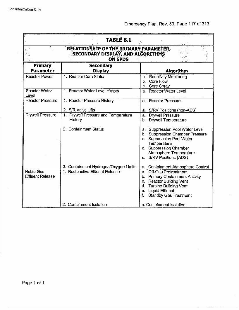
For Information Only
Emergency Plan, Rev. 59, Page 117 of 313
TABLE 8.1
"RELATI[ONSHIP. OF THE :PRIMARY PARAMETER, ,." ..:SEcoNDR ISPLY AND ALGO)RITHM."
________-___- oNisPiDS __________"__'_"::"_
Primary ISecondaryIParameter JDisplay jAlg orithm
Reactor Power 1. Reactor Core Status a. Reactivity Monitoringb. Core Flowc. Core Spray
Reactor Water 1. Reactor Water Level History a. Reactor Water LevelLevelReactor Pressure 1. Reactor Pressure History a. Reactor Pressure
_________2. S/R Valve Lifts a. S/RV Positions (non-ADS)Drywell Pressure 1. Drywell Pressure and Temperature a. Drywell Pressure
History b. Drywell Temperature
2. Containment Status a. Suppression Pool Water Levelb. Suppression Chamber Pressurec. Suppression Pool Water
Temperatured. Suppression Chamber
Atmosphere Temperaturee. S/RV Positions (ADS)
3. Containment Hydrogen/Oxygen Limits a. Containment Atmosphere ControlNoble Gas 1. Radioactive Effluent Release a. Off-Gas PretreatmentEffluent Release b. Primary Containment Activity
c. Reactor Building Ventd. Turbine Building Vente. Liquid Effluentf. Standby Gas Treatment
2. Containment Isolation a. Containment Isolation
Page 1 of 1
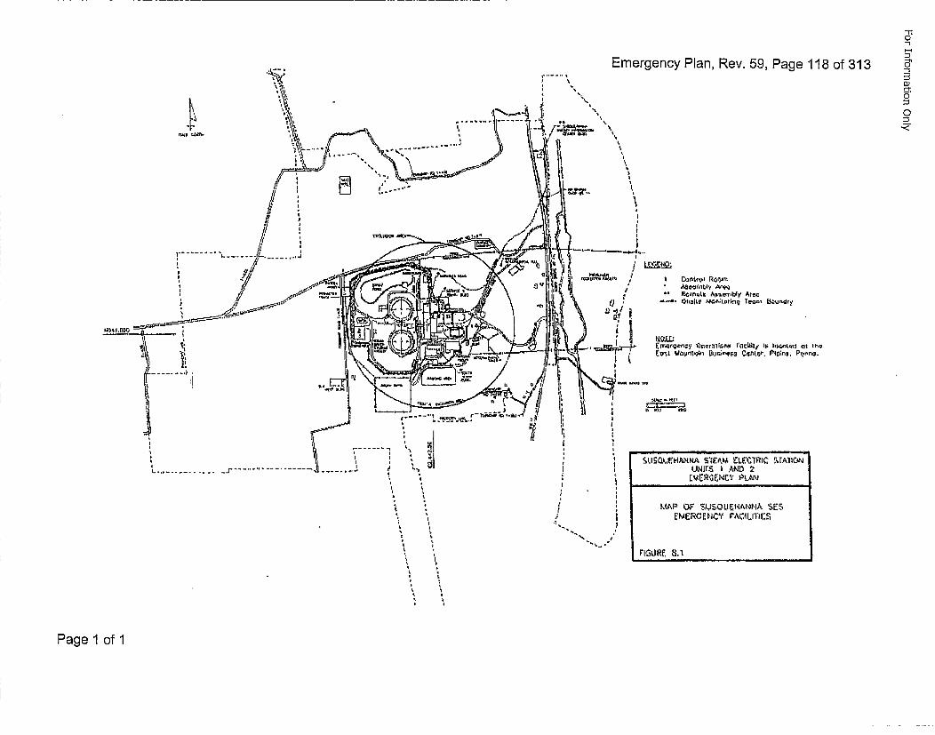
Emergency Plan, Rev. 59, Page 118 of 313
I
ouw1rs I AND 2
LIAR or• St1$LItIANNA'•I• SESF MERC;EN'CY VACILrITUS
rIGItRE=. a.d
%
i
i
Page 1 of 1
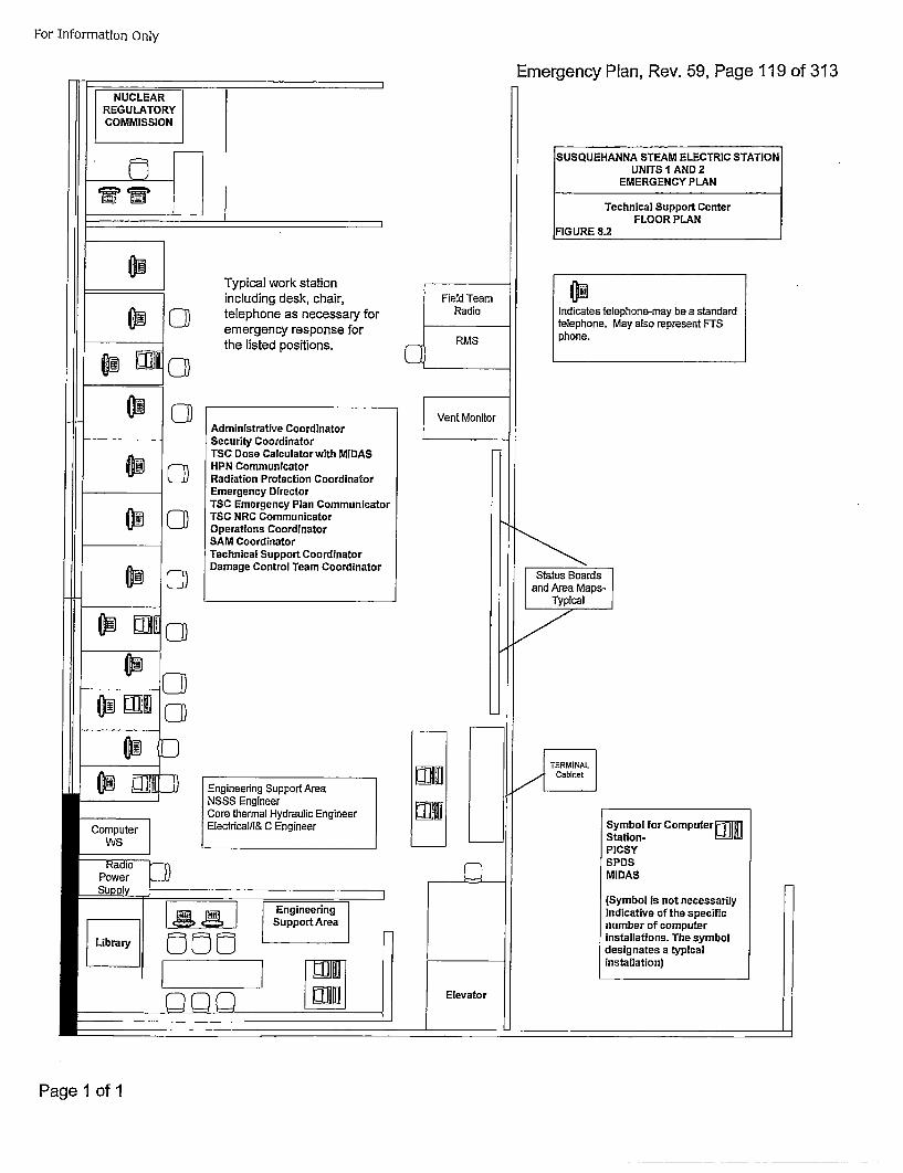
For Information Only
Emergency Plan, Rev. 59, Page 119 of 313
SUSQUEHANNA STEAM ELECTRIC STATIONUNITS I AND 2
I Technical Support CenterI FLOOR PLAN
]FIGURE 8.2
Typical work stationincluding desk, chair,telephone as necessary foremergency response forthe listed positions.
Indicates telephone-may be a standardtelephone. May also represent FTSphone.
cmAdministrative CoordinatorSecurity CoordinatorTSC Dose Calculator with MIDASHPN CommunicatorRadiation Protection CoordinatorEmergency DirectorTSC Emergency Plan CommunicatorTSC NRC CommunicatorOperations CoordinatorSAM CoordinatorTechnical Support CoordinatorDamage Control Team Coordinator
Engineering Support AreaNSSS EngineerCore thermal Hydraulic EngineerElectrlcal/l& C Engineer Symbol for Computer l------I1
Station- H4IUj~PICSYSPDSMIDAS
(Symbol is not necessarilyindicative of the specificnumber of computerinstallations. The symboldesignates a typicalinstallation)
Page 1 of 1
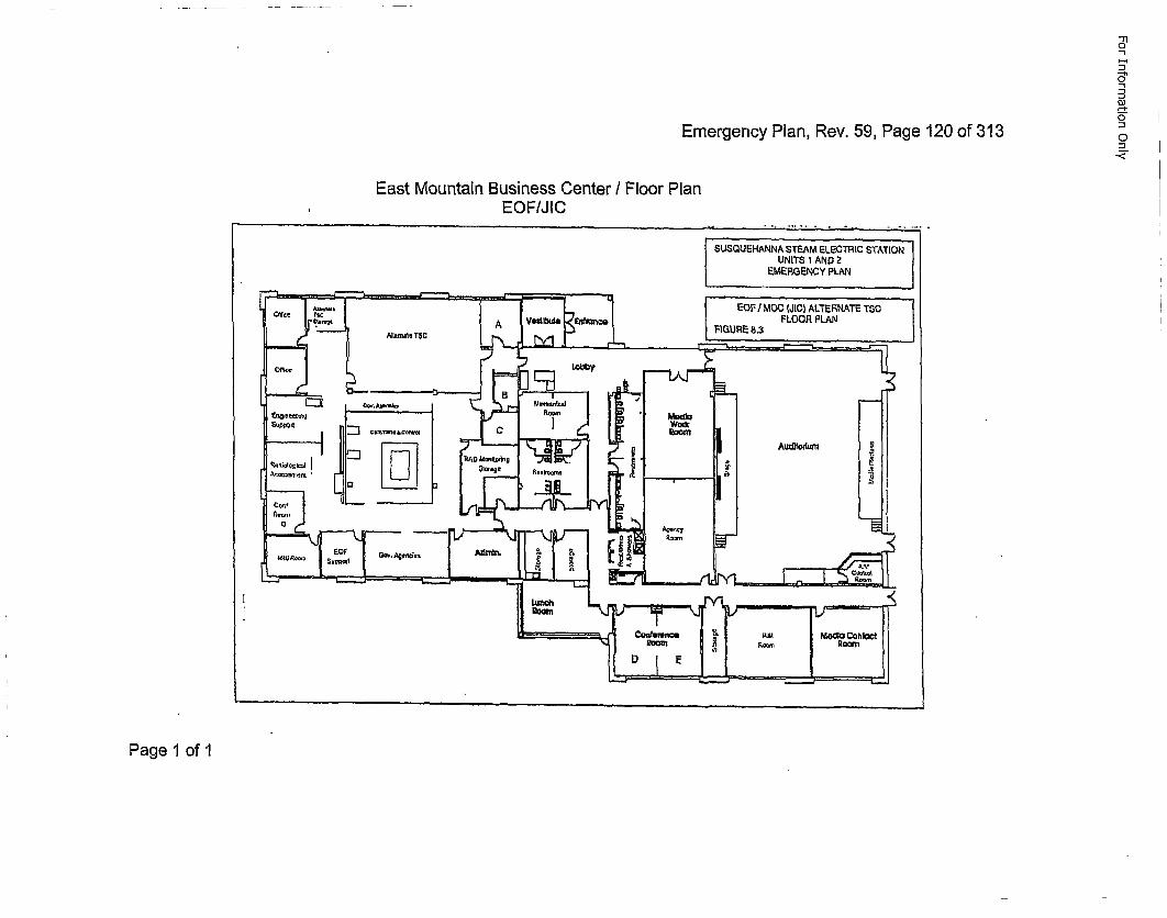
1*1
Emergency Plan, Rev. 59, Page 120 of 313o-<
East Mountain Business Center I Floor PlanEOFIJ IC
SU.SOUEI-ANNA ST2AM ELECTRIC STATIONUNITS 1 AND 2
SMERGENOY PLAN
EOFI/ MOO (JIC) ALTERNATE TSCFLOOR PLAN
Page 1 of 1
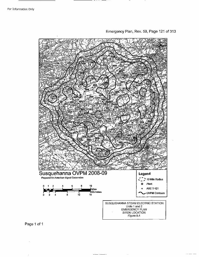
For Information Only
Emergency PRan, Rev. 59, Page 121 of 313
Susquehanna OVPM 2008-09Prepar'ed fr:. Amefrican Signal Corporation
SUSQUEHANNA STEAM ELECTRIC STATIONUnits 1 and 2
EMERGENCY PLANSIREN LOCATION
Figure 8.4
Page 1 of 1
For Information Only
Emergency Plan, Rev. 59, Page 122 of 313
9.0O MAINTAINING EMERGENCY PREPAREDNESS •
9.1 ORGANIZATIONAL PREPAREDNESS
9.1.1 Trainingq
a. All unescorted personnel entering or working within the SSESRadiologically Controlled Area receive as a minimum, thefollowing instruction:
* Appropriate portions of the SSES EP.
*Use of emergency facilities and equipment, familiarization withstation alarms and personnel response, and stationcommunications systems.
*Personnel accountability, evacuation, and radiation exposurecriteria.
* Radiation protection, emphasizing protective clothing,equipment, and personnel dosimetry.
b. Those individuals working on the SSES site, inside the protectedarea, but outside the Radiologically Controlled Area, are providedwith instructions on warning signals, accountability areas, andevacuation routes.
c. Personnel assigned to the Susquehanna ERO receive specializedtraining for their respective assignments. (Reference Table 9.1)
d. PEMA conducts a training program throughout the State andassists the counties in developing training policy for disasteroperational readiness. The county and local EMAs areresponsible for planning and conducting disaster preparednesstraining of respective emergency response personnel.Susquehanna works closely with PEMA and the county EMAs incoordinating training programs. In addition, orientation training forState and county agencies and personnel involved in SSESemergency planning efforts is made available by Susquehanna.
e. Annually, DEP/BRP and state, county, and municipal EMAs areinvited to participate in a training program conducted bySusquehanna. The initial training program relates the importanceof emergency planning and the interface between theSusquehanna and off~site ernerg~ency organizations with anemphasis on classification; EALs; reporting requirements;assessment, protective, and corrective actions; andcommunications networks. In addition, DEP/BRP is offered aspecific review of dose calculations/projections, protective actionsguides, and reportable information.
Page 1 of 6
For Information Only
Emergency Plan, Rev. 59, Page 123 of 313
f. The State Police, annually, are invited to participate in a trainingprogram on appropriate EP-PSs, with emphasis on theclassification of emergencies, communications, and specific areasof responsibility.
g. Susquehanna provides training annually to local off-site supportorganizations. These local organizations are encouraged tobecome familiar with the SSES, key station personnel, and areinvited to attend training conducted by or for Susquehanna.
Initial core training for local fire companies and ambulanceassociations includes:
* Interface with the Site Security Force• Basic health physics indoctrination and training* SSES facility layout
Fire companies also receive training in the following areas:
* On-site fire protection system equipment* Differences between on-site firefighting equipment and fire
company supplied equipment* Communications system* Review of sections of the SSES EP and EP-PSs* The on-site ERO with emphasis on the interface between the
SSES fire brigade and fire company personnel
h. Personnel assigned to the Emergency Planning Organizationreceive training as required by EP administrative procedures.Emergency Planning experience may be used in lieu of training.
Each year a fire drill, which includes local fire company support, is held totest these areas.
Annually local ambulance associations are invited to attend specializedtraining regarding the handling of contaminated/injured victims.
Page 2 of 6
For Information Only
Emergency Plan, Rev. 59, Page 124 of 313
9.1.2 Drills and Exercises
Each drill or exercise is conducted to: (1) ensure that the participants arefamiliar with their respective duties and responsibilities, (2) verify theadequacy of the SSES EP procedures, (3) test communications networksand systems, (4) determine availability and operability of emergencysupplies and equipment, and (5) every two years verify the adequacy ofoff-site agency plans.
Drills and exercises are conducted to simulate actual emergencyconditions as closely as possible and may be scheduled such that morethan one type of the following drills or exercises can be conductedsimultaneously to meet the guidance of NUREG-0654 and therequirements of I0CFR50:
• Annual medical drill involving offsite support* Annual fire drill involving offsite support* Annual radiological drill to site area or general emergency level with
offsite participation biennially* Annual full-scale ANS test* Annual environmental monitoring drill* Semi-annual Health Physics drill testing survey sampling and analysis
techniques* Annual drill that tests ability to obtain and analyze a post accident
coolant sample* Perform augmentation exercise every eight years* Hostile Action Based exercise every eight years
Additional non-integrated drills and tests are conducted as follows:
• Bi-weekly Silent Tests for sirens* Quarterly Growl Tests for sirens* Quarterly fire drills* Monthly communications drills with state and county agencies* Monthly communications tests with the NRC
Drill scenarios for major drills are prepared to involve participation ofseveral emergency teams and all or specific parts of the ERO includingvarying degrees of participation of State, County, and Federal agenciesand focal off-site support organizations.
Following the conduct of drills, critiques are held to clearly identifydeficiencies and action plans for resolution. Procedures are establishedto assure the timely implementation of corrective actions.
Ingestion pathway exercises are conducted by the offsite agencies inaccordance with PEMA Annex E. Susquehanna Steam Electric Stationpersonnel provide support as required.
Page 3 of 6
For Information Only
Emergency Plan, Rev. 59, Page 125 of 313
9.1.3 Overall Coordination of Nuclear Emergqency Preparedness
The Manager-Emergency Preparedness is responsible for the overallcoordination of all nuclear emergency planning activities. TheManager-Emergency Preparedness is assisted in this effort by: the PlantManager for activities involving the Susquehanna Site, the GeneralManager-Nuclear Engineering for engineering issues, theManager-Nuclear Training for on-site training, the Community RelationsManager-Susquehanna for communications with the public and newsmedia, and the Manager-Nuclear Oversight for audits of EmergencyPlanning.
The Manager-Emergency Preparedness is typically responsible for:
* Revising of the SSES Emergency Plan* Revising of EP-PSs and other Emergency Planning Administrative
procedures• Conducting of integrated drills and exercises and communication drills* Defining EP training scope for ERO* Defining EOF and JIC EP Training• Coordinating EP interface between State and Federal agencies* Coordinating maintenance and testing of ANS• Coordinating interface between state, county, municipal, and
Susquehanna ERO* Assuring operational readiness of Emergency Response Facilities
Page 4 of 6
For Information Only
Emergency Plan, Rev. 59, Page 126 of 313
9.2 REVIEW AND UPDATING9.2.1 SSES Emerqency Plan
The Manager-Emergency Preparedness is responsible for the review andrevision of the SSES Emergency Plan, ensuring:
* A review of the SSES Emergency Preparedness Program isperformed periodically by persons who have no direct responsibilityfor implementation of the program in accordance with 10OCFR50.54t.
* Annual review of the SSES Emergency Plan.
* Annual review of Letters of Agreement.
* Recommendation of Emergency Plan changes to PORO.
* PORC review of Emergency Plan changes and submission ofchanges to NSRB.
* Revisions or a report of change to the Emergency Plan that do notchange the effectiveness of the plan are submitted to the NRC within30 days from the implementation of such change(s).
* Perform an annual review of the Evacuation Time Estimate (ETE) toensure 10OCFR50 Appendix E Section IV and NUREG 0654 ElementJ.8 requirements are maintained. Update the full ETE should thecriteria from Appendix E be met and re-submit the ETE to the NRC.
9.2.2 Emergqency Plan Procedures
The Manager-Emergency Preparedness is responsible for the review andrevision(s) of the Emergency Plan Procedures, ensuring:
* The periodic review is accomplished in accordance with establishedplant procedures.
° Revisions to procedures are done in accordance with establishedplant procedures.
* Controlled copies of procedure revisions are issued by stationdocument control programs.
* ERO personnel are briefed on revisions as required.
Page 5 of 6
For Information Only
Emergency Plan, Rev. 59, Page 127 of 313
9.3 MAINTENANCE AND INVENTORY OF EMERGENCY EQUIPMENT/SUPPLIESThe Manager-Emergency Preparedness is responsible for periodic inventory andinspection of emergency equipment and supplies, and for periodic testing of emergencycommunic~ations systems. This testing includes verification of phone numbers that arecontained in Emergency Plan procedures.
Equipment, supplies, and parts having limited shelf lives are checked and replaced asnecessary. Monthly communications drills and tests are also conducted from SusquehannaERFs and offsite agencies.
Any deficiencies found during these activities are either cleared immediately ordocumented for corrective action.
9.4 PUBLIC EDUCATION AND INFORMATION
Under the direction of the Manager-Emergency Preparedness, the following methodsare utilized to ensure that emergency planning information and education is providedand transmitted to residents and transients in the EPZ annually.
9.4.1 Telephone Directory Inserts
With the cooperation of Pennsylvania Emergency Management Agency,Luzerne County Emergency Management Agency, and Columbia CountyEmergency Management Agency, emergency information is provided inall telephone directories distributed within the ten mile EPZ. Thisinformation includes:
• explanation of Emergency Classifications* what to do when you hear the sirens* public Protective Actions* student pick-up points* evacuation routes to reception centers* evacuation Plan Map* callback number for special needs
9.4.2 Programs are Offered to Acquaint the News Media With:
* SSES Emergency Plan* information concerning radiation* points of contact for the release of public information during an
emergency
9.4.3 Educational Traininq Progqrams
Educational training programs on emergency preparedness are madeavailable to the general public through the staffs of the SusquehannaEnergy Information Center and Nuclear Emergency Preparedness.
Page 6 of 6
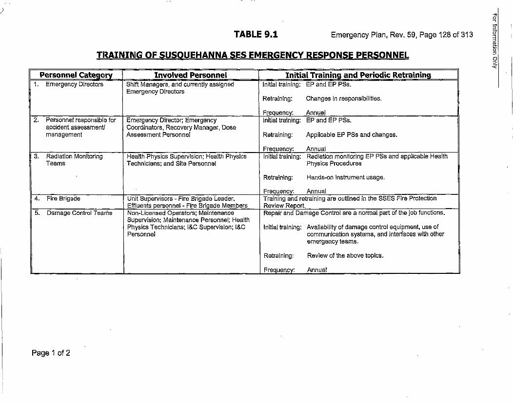
TABLE 9.1 Emergency Plan, Rev. 59, Page 128 of 313
-n0-l
DI
0
0TRAINING OF SUSQUEHANNA SES EMERGENCY RESPONSE PERSONNEL
Personnel Category .... Involved Personnel Iinitial Training and Periodic Retraining1. Emergency Directors Shift Managers, and currently assigned Initial training: EP and EP PSs.
Emergency DirectorsRetraining: Changes in responsibilities.
Frequency: Annual2. Personnel responsible for Emergency Director; Emergency Initial training: EP and EP PSs.
accident assessmentl Coordinators, Recovery Manager, Dosemanagement Assessment Personnel Retraining: Applicable EP PSs and changes.
_____________________Frequency: Annual3. Radiation Monitoring Health Physics Supervision; Health P5hysics Initial training: Radiation monitoring EP PSs and applicable Health
Teams Technicians; and Site Personnel Physics Procedures
Retraining: Hands-on instrument usage.
Frequency: Annual4. Fire Brigade Unit Supervisors - Fire Brigade Leader, Training and retraining are outlined in the SSES Fire Protection
Effluents personnel - Fire Brigade Members Review Report.5.' Damage Control Teams Non-Licensed Operators; Maintenance Repair and Damage Control are a normal part of the'job functions.
Supervision; Maintenance Personnel; HealthPhysics Technicians; l&C Supervision; l&C Initial training: Availability of damage control equipment, use ofPersonnel communication systems, and interfaces with other
emergency teams.
Retraining: Review of the above topics,
_____________________ ________________________________Frequency: Annual
Page 1 of 2
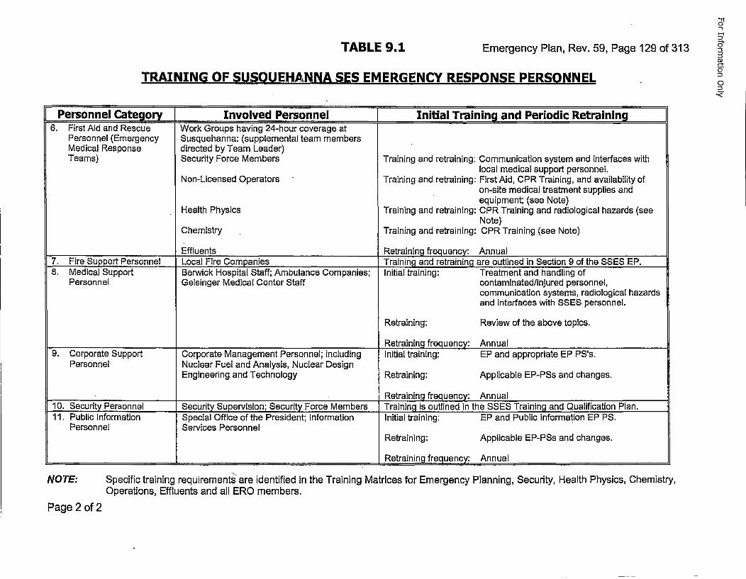
TABLE 9,1 Emergency Plan, Rev. 59, Page 129 of 313
TRAINING OF SUSQUEHANNA SES EMERGENCY RESPONSE PERSONNEL
Personnel Categoryj Involved Personnel Initial Training and Periodic Retraining6. First Aid and Rescue Work Groups having 24-hour coverage at
Personnel (Emergency Susquehanna: (supplemental team membersMedical Response directed by Team Leader)Teams) Security Force Members Training and retraining: Communication system and interfaces with
local medical support personnel.Non-Licensed Operators Training and retraining: First Aid, CPR Training, and availability of
on-site medical treatment supplies andequipment; (see Note)
Health Physics Training and retraining: CPR Training and radiological hazards (seeNote)
Chemistry Training and retraining: CPR Training (see Note)
______________Effluents Retraining frequency: Annual7. Fire Support Personnel Local Fire Companies Trainin~g and retraining are outlined in Section 9 of the SSES EP.8. Medical Support Berwick Hospital Staff; Ambulance Companies; Initial training: Treatment and handling of
Personnel Geisinger Medical Center Staff contaminated/injured personnel,communication systems, radiological hazardsand interfaces with SSES personnel.
Retraining: Review of the above topics.
_________________________________Retraining frequency: Annual9. Corporate Support Corporate Management Personnel; including Initial training: EP and appropriate EP PS's.
Personnel Nuclear Fuel and Analysis, Nuclear DesignEngineering and Technology Retraining: Applicable EP-PSs and changes.
Retraining frequency: Annual10. Security Personnel Security Supervision; Security Force Members Training is outlined in the SSES Training and Qualification Plan.11. Public Information Special Office of the President; Information Initial training: EP and Public Information EP PS.
Personnel Services PersonnelRetraining: Applicable EP-PSs and changes.
________________________________________________________Retraining frequency: Annual
NOTE: Specific training requirements are identified in the Training Matrices for Emergency Planning, Security, Health Physics, Chemistry,Operations, Effluents and all ERG members.
Page 2 of 2

For Information Only
Emergency Plan, Rev. 59, Page 130 of 313
APPENDIX A
LETTERS OF AGREEMENT
Page 1 of 3
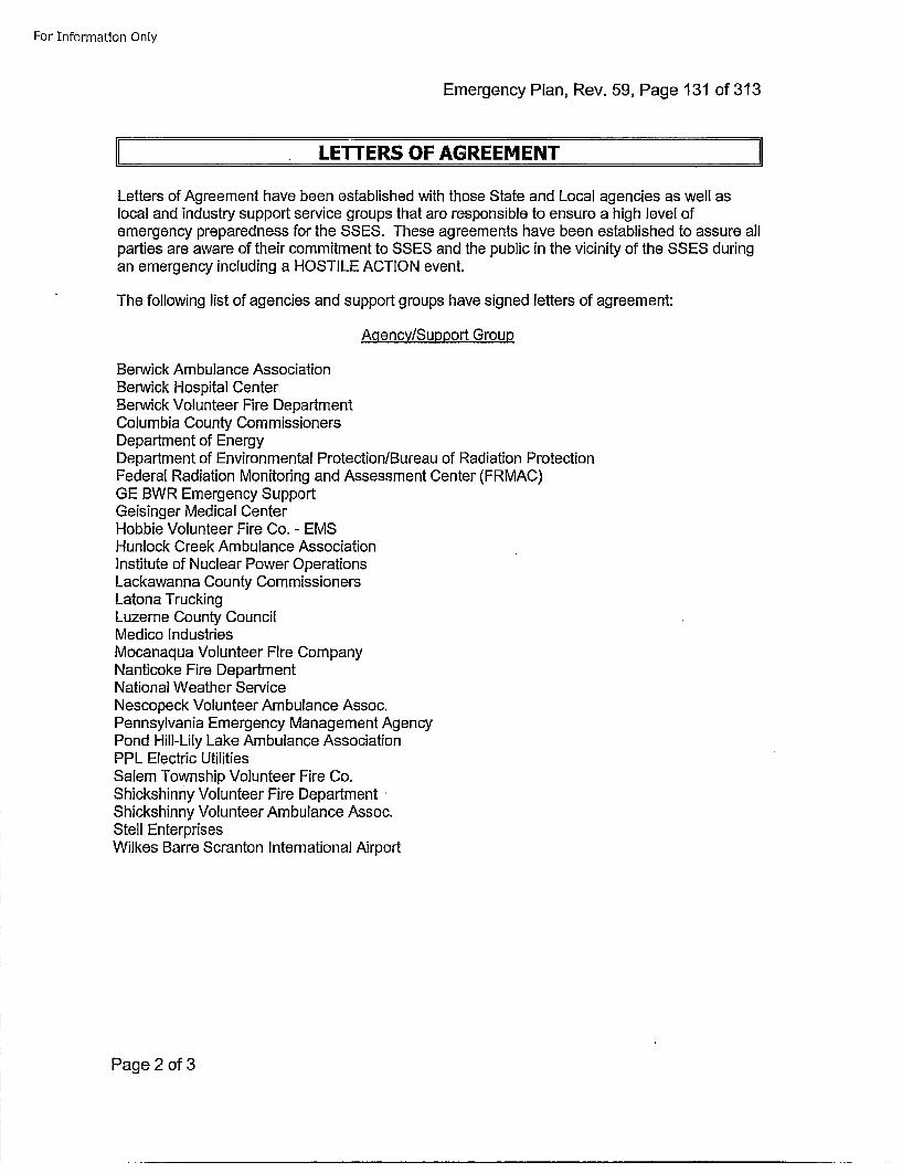
For Information Only
Emergency Plan, Rev. 59, Page 131 of 313
LE1TrERS OF AGREEMENT
Letters of Agreement have been established with those State and Local agencies as well aslocal and industry support service groups that are responsible to ensure a high level ofemergency preparedness for the SSES. These agreements have been established to assure allparties are aware of their commitment to SSES and the public in the vicinity of the SSES duringan emergency including a HOSTILE ACTION event.
The following list of agencies and support groups have signed letters of agreement:
A qency/Support Group
Berwick Ambulance AssociationBerwick Hospital CenterBerwick Volunteer Fire DepartmentColumbia County CommissionersDepartment of EnergyDepartment of Environmental Protection/Bureau of Radiation ProtectionFederal Radiation Monitoring and Assessment Center (ERMAC)GE BWR Emergency SupportGeisinger Medical CenterHobbie Volunteer Fire Co. - EMSHunlock Creek Ambulance AssociationInstitute of Nuclear Power OperationsLackawanna County CommissionersLatona TruckingLuzerne County CouncilMedico IndustriesMocanaqua Volunteer Fire CompanyNanticoke Fire DepartmentNational Weather ServiceNescopeck Volunteer Ambulance Assoc.Pennsylvania Emergency Management AgencyPond Hill-Lily Lake Ambulance AssociationPPL Electric UtilitiesSalem Township Volunteer Fire Co.Shickshinny Volunteer Fire DepartmentShickshinny Volunteer Ambulance Assoc.Stell EnterprisesWilkes Barre Scranton International Airport
Page 2 of 3
For Information Only
Emergency Plan, Rev. 59, Page 132 of 313
These letters of agreement provide for:
* Coordination of planning efforts by State and loca] agencies; industry support groups;fire ambulance and hospital support services; and Susquehanna.
* Appropriate emergency response to assure employee and public safety during anemergency condition at SSES.
* Mutual notification capabilities.* Appropriate training and exercising of emergency response capabilities.* Fire, first aid and medical support.* Environmental monitoring and assessment support.* Other emergency support services as deemed necessary
The Manager-Emergency Preparedness is responsible for renewing letters of agreement everyyear where applicable. In some instances, where the letter of agreement is for a specifiedduration longer than 1 year, letters need not be renewed until the end of the specified duration.Copies are maintained and controlled within Document Control Services to assure appropriatereview and updating takes place.
Page 3 of 3
For Information Only
Emergency Plan, Rev. 59, Page 133 of 313
APPENDIX B
WIND ROSES,
DOSE/DISTANCE PLOTS AND
JOINT FREQUENCY DISTRIBUTION
Page 1 of 17
For Information Only
Emergency Plan, Rev. 59, Page 134 of 313
I ~ORIGINAL DOCUMENT ISSUED 01/1992!SPECIFIC FIGURES MAY HAVE OTHER ISSUE DATES.
INTERPRETATION OF WIND ROSES I
Perhaps the best way to discuss the interpretation is to take a specific example. Let us considerthe wind rose for Spring (Figure I). This wind rose represents the average wind conditions atthe 10 meter level for a total of 4 Springs (1973-1976). Spring is defined as the months ofMarch, April, and May. Similarly Summer consists of June, July, and August, Autumn isSeptember, October, and November, and Winter is December, January, and February.
In looking at Figure I we see that the winds are most frequently from the West. Thus they willcarry plant effluents towards the East. We also see that 11.5% of all the winds are from theWest. Winds from the West at speeds of 0-1.5 meters per second (raps) comprise 1.6% of allwinds; winds from the West at speeds of 1.5-5.0 mps comprise 6.9% of all winds; winds fromthe West at speeds of greater than 5 mps comprise 3.0% of all winds.
We can also see that 0.8% of all the winds are calm and therefore are not assigned a direction.In addition the least frequent winds are from the Southeast.
It is also apparent that the lightest winds (0-1.5 mps) most frequently are associated with windsfrom the East-Northeast and East while the strongest winds (greater than 5 mps) are mostfrequently associated with winds from. the West.
Page 2 of 17
For Information Only
Emergency Plan, Rev. 59, Page 135 of 313
J INTERPRETATION OFDOSE/DISTANCE PLOTS
The dose/distance plots have been removed and reference to the use of MIDAS as theapproved methodology/tool for determining magnitude of and for continually assessing theimpact of the release.
MIDAS has the capability to provide assessments using event-specific fuel damage estimates.Additionally, MIDAS can provide information at additional distances than were provided in thedeleted Dose/Distance nomographs. The system performs estimates and predictions ofatmospheric effluent transport and diffusion during and immediately following an accidentalairborne radioactive release from the facility.
Page 3 of 17
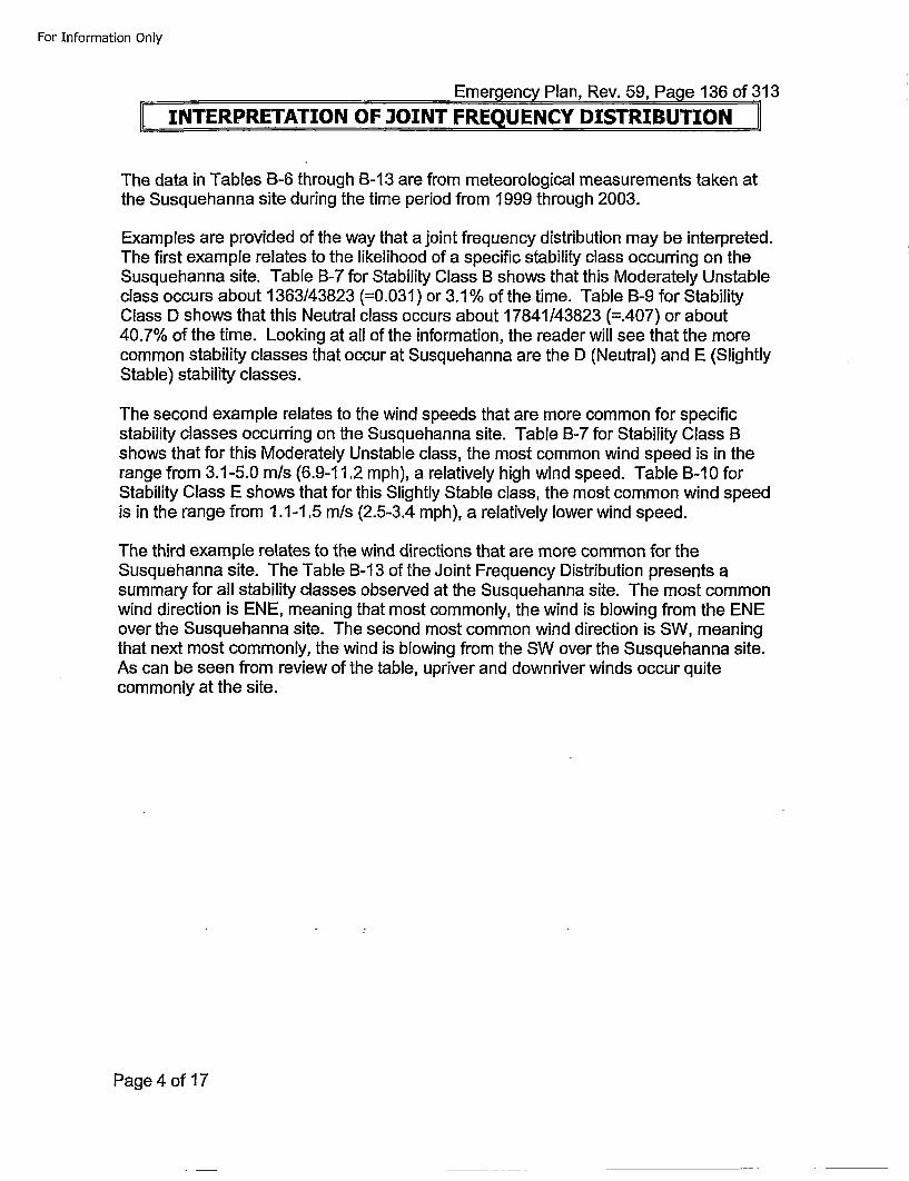
For Information Only
Emergency Plan, Rev. 59, Page 136 of 313[[INTERPRETATION OF JOINT FRE UENCY DISTRIBUTION I
The data in Tables B-6 through B-I13 are from meteorological measurements taken atthe Susquehanna site during the time period from 1999 through 2003.
Examples are provided of the way that a joint frequency distribution may be interpreted.The first example relates to the likelihood of a specific stability class occurring on theSusquehanna site. Table B-7 for Stability Class B shows that this Moderately Unstableclass occurs about 1363/43823 (=0.031) or 3.1% of the time. Table B-9 for StabilityClass D shows that this Neutral class occurs about 17841/43823 (=.407) or about40.7% of the time. Looking at all of the information, the reader will see that the morecommon stability classes that occur at Susquehanna are the D (Neutral) and E (SlightlyStable) stability classes.
The second example relates to the wind speeds that are more common for specificstability classes occurring on the Susquehanna site. Table B-7 for Stability Class Bshows that for this Moderately Unstable class, the most common wind speed is in therange from 3.1-5.0 m/s (6.9-11t.2 mph), a relatively high wind speed. Table B-I10 forStability Class E shows that for this Slightly Stable class, the most common wind speedis in the range from 1.1-1.5 m/s (2.5-3.4 mph), a relatively lower wind speed.
The third example relates to the wind directions that are more common for theSusquehanna site. The Table B-I13 of the Joint Frequency Distribution presents asummary for all stability classes observed at the Susquehanna site. The most commonwind direction is ENE, meaning that most commonly, the wind is blowing from the ENEover the Susquehanna site. The second most common wind direction is SW, meaningthat next most commonly, the wind is blowing from the SW over the Susquehanna site.As can be seen from review of the table, upriver and downriver winds occur quitecommonly at the site.
Page 4 of 17
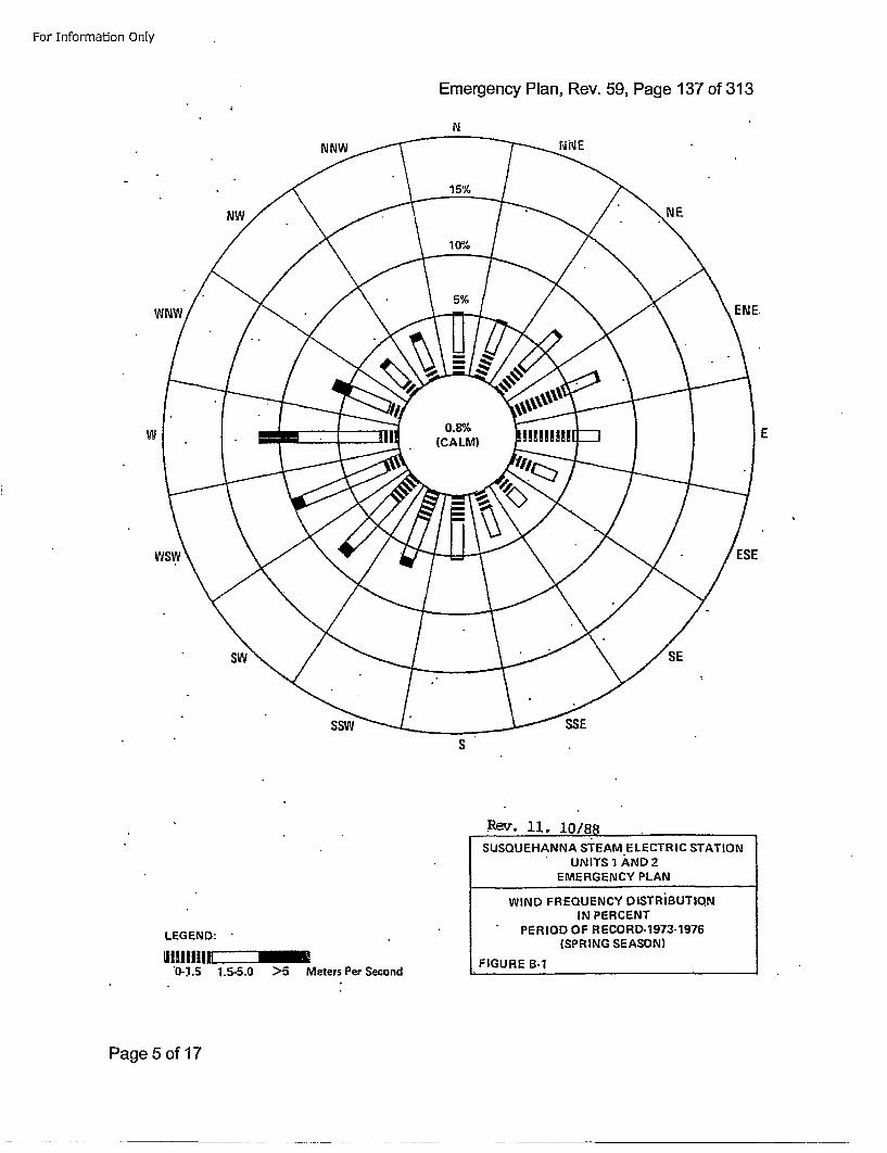
For Information Only
Emergency Plan, Rev. 59, Page 137 of 313
N
W E
S
Rev. 11, 10/8sSUSQUEHANNA STEAM ELECTRIC STATION
UNITS 1 AND 2EMERGENCY PLAN
WIND FREQUENCY DISTRIBUTIQN
IN PERCENTPERIOD OF RECORD-1973-'1976
(SPRING SEASON I
FIGURE B-1
LEGEND:IlIllIllEZIZZ~l
"0-.1.5 1.5-5.0 >5 Meters Per Second
Page 5 of 17
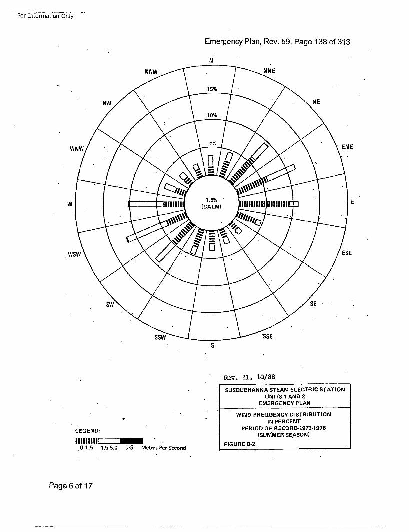
For Information-Only -.
Emergency Plan, Rev. 59, Page 138 of 313
N
ENE
E
ESE
S
Re=v. 11, 10/88SUSQUE-HANNA STEAM ELECTRIC STATION
UNITS 1 AND 2EMERGENCY PLAN
WIND FREQUENCY DISTRIBUTIONIN PERCENT"
PERIOD:OF RECORD-1973-1976(SUMMER SE.AS.ON)
FIGURE B-2.
LEGEND:
IIII~IIIIr•zzzl0-1.5 1,5-5.0 ;'5 Meters Per Second
Page 6 of 17
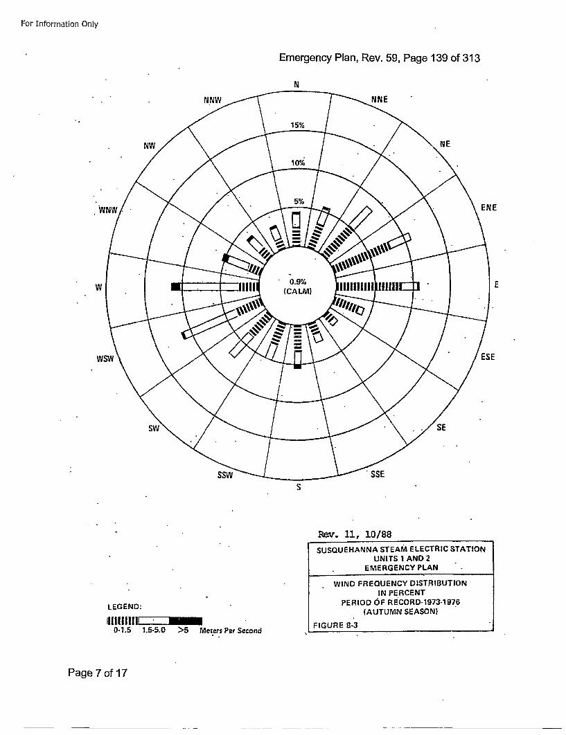
For Information Only
Emergency Plan, Rev. 59, Page 139 of 313
ENE
E
ESE
S
SUSQUEHANNA STEAM ELECTRIC STATION
UNITS I AND 2EMERGENCY PLAN
WIND FREQUENCY DIST.RIBUTIONIN PERCENT
PERIOD OiF RISCORD-1973-1 976
(AUTUMN SEASON)
FIGURE B-3
LEGEND:111l1lllllEZZZZZfB~
0-1.5 1.5-5.0 >5 Meters Per Second
Page 7 of 17
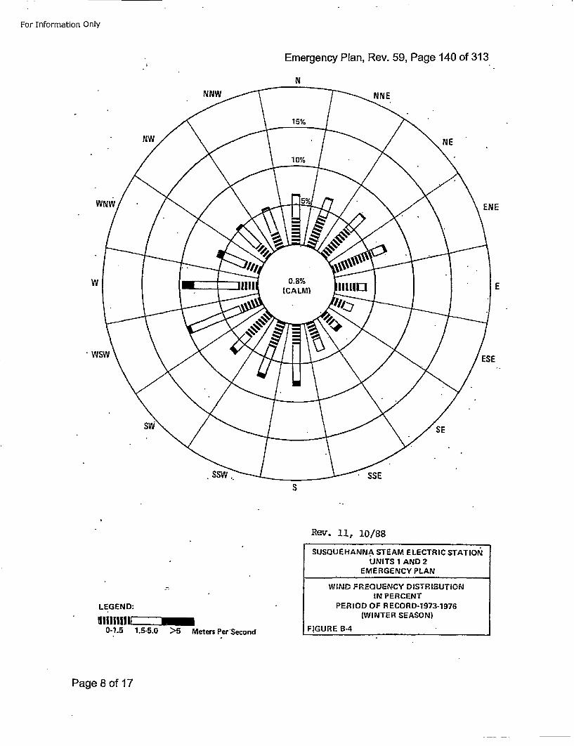
For Information Only
Emergency Plan, Rev. 59, Page 140 of 313
N
ENE
w!.ws
E
ESE
S
Rev'. 11, 10/88SUSGUEHANNA STEAM ELECTRIC STATION•
UNITS 1 AND 2EMERGENCY PLAN
WIND FREQUENCY DISTRIBUTiONIN PERCENT
PERIOD OF R ECORD-1973-1976(WINTER SEASON)
FIGURE B-4
LEGEND:I!111111 ZZI
0-1.5 1.5-5.0 >5 Meters Per'Second
Page 8 of 17
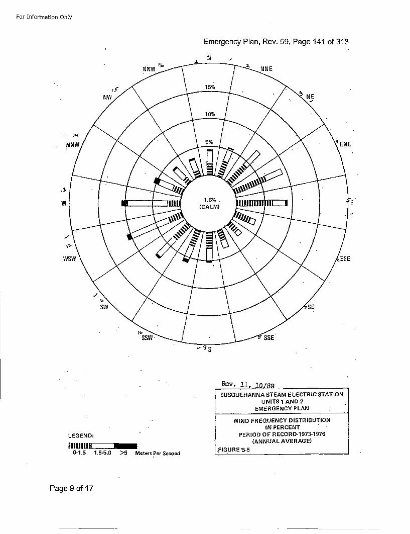
For Information Only
Emergency Plan, Rev. 59, Page 141 of 313
N
W
Rev. ii, 1o/s88 _______SUSQU EHANNA STEAM E LECTRIC STAT ION
UNITS 1 AND 2EMERGENCY PLAN
WIND FREQUENCY DISTR IBUTIONIN PERCENT
PERIOD OF RECORD-1973-1976
(ANNUAL AVERAG E)
.FIGURE B-5
LEG END:II11III1111 ZII
0-1.5 1.5-5.0 >5 Meters Per Second
Page 9 of 17
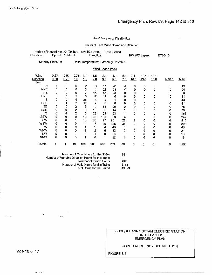
For Information Only
Emergency Plan, Rev. 59, Page 142 of 313
Joint Frequency Distribution
Hours at Each Wind Speed and Direction
Period of Record = 01/01/99 1:00 - 12131/03 23:00 Total PeriodElevation: Speed: 10M SPD Direction: l0M WD Lapse: DT60-1 0
Stability Class: A Delta Temperature: Extremely Unstable
Wind Speed (mis)
Wind 0.23- 0.51- 0.76- 1.1- 1.6- 2.1- 3.1- 5.1- 7.1- 10.1- 13.1-Direction 0.50 0.75 1.0 1.5 2.0 3._0 5.0 7.0 10.0 13.0 18.0
from> 18.0 Total
NNNE
NEENE
EESE
SESSE
SSSW
SWWSW
WWNW
NWNNW
1000000000000000
00000I0000000000
0 2 3 11 280 3 1 28 580 7 15 45 231 8 17 11 44 26 8 4 17 12 7 8 62 6 14 33 202 6 19 36 142 10 28 62 630 12 38 105 881 10 38 177 2610 4 7 29 1250 1 2 4 480 1 2 6 120 0 1 0 60 1 0 1 12
4400000114
2835
5034
0000000000120000
0000000000000000
0000000000000000
0000000000000000
499490414341757816624751620260211018
Totals 1 1 19 109 200 560 769
Number of Calm Hours for this TableNumber of Variable Direction Hours for this Table
Number of Invalid HoursNumber of Valid Hours for this Table
Total Hours for the Period
89 3 0 0
18a297175143823
0 1751
SUSQUEHAN NA STEAM ELECTRIC STATIONUNITS 1 AND 2
EMERGENCY PLAN
JOINT FREQUENCY DISTRIBUTION
FIGURE B-6Page 10 of 17

For Information Only
Emergency Plan, Rev. 59, Page 143 of 313
Joint Frequency Distribution
Hours at Each Wind Speed and Direction
Period of Record = 01/01/99 1:00- 12131/03 23:00 Total PeriodElevation: Speed: 10M SPD Direction: l0M WD Lapse: DT60-1 0
Stability Class: B Delta Temperature: Moderately Unstable
Wind Speed (mis)
Wind 0.23- 0.51- 0.76- 1.1- 1.6- 2.1- 3.1- 5.1- 7.1-Direction 0.50 0.75 1.0 1.5 2.0 3.0 5.0 7.0 10.0from
N 0 1 0 1 5 9 42 8 0NNE 0 0 0 3 20 47 34 3 0
NE 0 0 0 12 16 46 24 0 0ENE 0 0 1 24 13 10 2 0 0
E 0 0 9 15 7 10 3 0 0ESE 0 0 4 11 14 5 5 0 0
SE 0 0 2 10 11 16 11 0 0SSE 0 0 0 4 11 11 6 0 0
5 0 0 2 11 14 38 21 0 0SSW 0 0 1 11 39 55 28 3 0
SW 0 0 0 4 36 105 175 31 4WSW 0 0 1 1 7 23 100 43 2
W 0 0 0 0 1 8 34 4 0WNW 0 0 0 0 1 1 18 1 0
NW 0 0 0 0 1 5 10 2 0NNW 0 0 0 0 4 8 19 3 2
10.1- 13.1-13.0 18.0 > 18.0 Total
0000000000000000
0000000000000000
0000000000000000
661079850443950328613735517747211836
Totals 0 1 20 107 200 397 532
Number of Calm Hours for this TableNumber of Variable Direction Hours for this Table
Number of Invalid HoursNumber of Valid Hours for this Table
Total Hours for the Period
98 8 0 0 0 1363
180297136343823
SUSQUEHANNA STEAM ELECTRIC STATIONUNITS I AND 2
EMERGENCY PLAN
JOINT FREQUENCY DISTRIBUTION
FIGURE B-7Page 11 ofl17
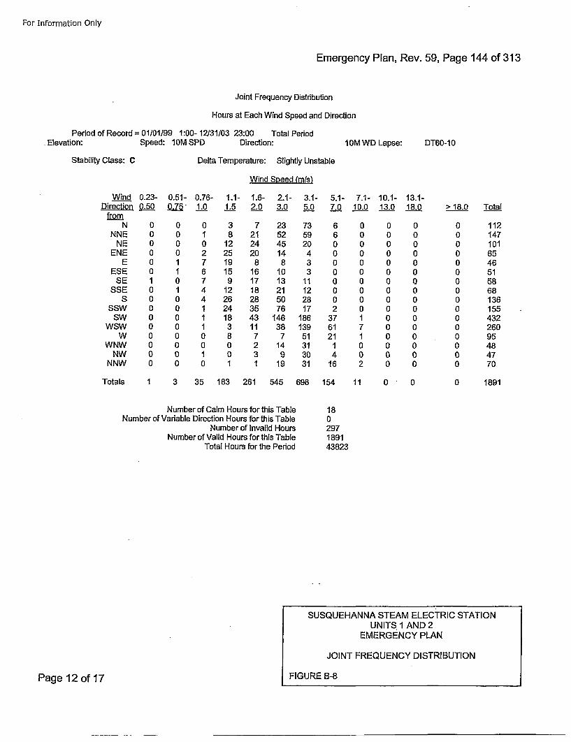
For Information Only
Emergency Plan, Rev. 59, Page 144 of 313
Joint Frequency Distribution
Hours at Each Wind Speed and Direction
Period of Record = 01/01/99 1:00- 12131103 23:00 Total Period•Elevation: Speed: 1DM SPD Direction: IOM WD Lapse: DT60-10
Stability Class: C Delta Temperature: Slightly Unstable
Wind Speed (mis)
Wind 0.23- 0.51- 0.76- 1.1- 1.6- 2.1- 3.1- 5.1- 7.1- 10.1- 13.1-Direction 0.50 0.75. 1.0 1.5 2.._0 3.0 5.0 7.0 10.0 13.0 18.0.from
N 0 0 0 3 7 23 73 6 0 0 0NNE 0 0 1 8 21 52 59 6 0 0 0
NE 0 0 0 12 24 45 20 0 0 0 0ENE 0 0 2 25 20 14 4 0 0 0 0
E 0 1 7 19 8 8 3 0 0 0 0ESE 0 1 6 15 16 10 3 0 0 0 0
SE 1 0 7 9 17 13 11 0 0 0 0SSE 0 1 4 12 18 21 12 0 0 0 0
S 0 0 4 26 28 50 28 0 0 0 0SSW 0 0 1 24 35 76 17 2 0 0 0
SW 0 0 1 18 43 146 186 37 1 0 0WSW 0 0 1 3 11 38 139 61 7 0 0
W 0 0 0 8 7 7 51 21 1 0 0WNW 0 0 0 0 2 14 31 1 0 0 0
NW 0 0 1 0 3 9 30 4 0 0 0NNW 0 0 0 1 1 19 31 16 2 0 0
> 18.0 Total
0000000000000000
112147101654651586813615543226095484770
Totals 1 3 35 183 261 545 698
Number of Calm Hours for this TableNumber of Variable Direction Hours for this Table
Number of Invalid HoursNumber of Valid Hours for this Table
Total Hours for the Period
154 11 0 0 0 1891
180297189143823
SUSQUEHANNA STEAM ELECTRIC STATIONUNITS 1 AND 2
EMERGENCY PLAN
JOINT FREQUENCY DISTRIBUTION
FIGURE 8-8Page 12 of 17
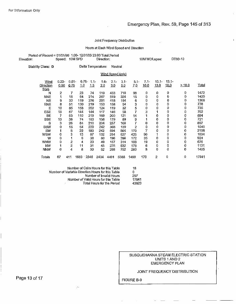
For Information Only
Emergency Plan, Rev. 59, Page 145 of 313
Joint Frequency Distribution
Hours at Each Wind Speed and Direction
Period of Record = 01101199 1:00- 12131103 23:00 Total PeriodElevation: Speed: 10M SPD) Direction: 10M WID Lapse: DT60-10
Stability Class: D Delta Temperature: Neutral
Wind Soeed (mis)
WindDirection
fromN
NNENE
ENEE
ESESE
SSES
SSWSW
WSWW
WNWNW
NNW
0,23- 0.51- 0.76- 1.1- 1.6- 2.1- 3.1- 5.1- 7.1- 10.1- 13.1-0.50 0.75 1.0 1.5 2.0 3.0 5.0 7..00 10.__0 13.0 18.0 > 18.0 Total
2 7 23 74 119 433 716 981 16 64 214 267 519 324 159 33 119 276 281 418 164 68 51 130 219 153 158 54 3
10 85 158 202 124 119 32 515 67 144 144 117 146 58 77 53 110 219 169 200 121 14
10 38 74 163 158 179 89 93 26 84 210 204 257 106 70 15 54 220 242 368 139 21 8 29 193 242 594 864 1700 3 15 87 132 254 627 4250 1 6 38 80 196 396 1720 2 4 23 49 157 314 1081 2 11 31 45 225 632 1780 4 8 33 52 268 752 280
00000311007
90351968
0000010000010000
0000000000000000
0000000000000000
14721420130677673570289472189710402108163492467611311405
Totals 67 411 1033 "2346 2434 4491 5388 1499 170 2 0 0 17841
Number of Calm Hours for this TableNumber of Variable Direction Hours for this Table
Number of Invalid HoursNumber of Valid Hours for this Table
Total Hours for the Period
1802971784143823
SUSQUEHANNA STEAM ELECTRIC STATIONUNITS 1 AND 2
EMERGENCY PLAN
JOINT FREQUENCY DISTRIBUTION
FIGURE B-9Page 13 of 17
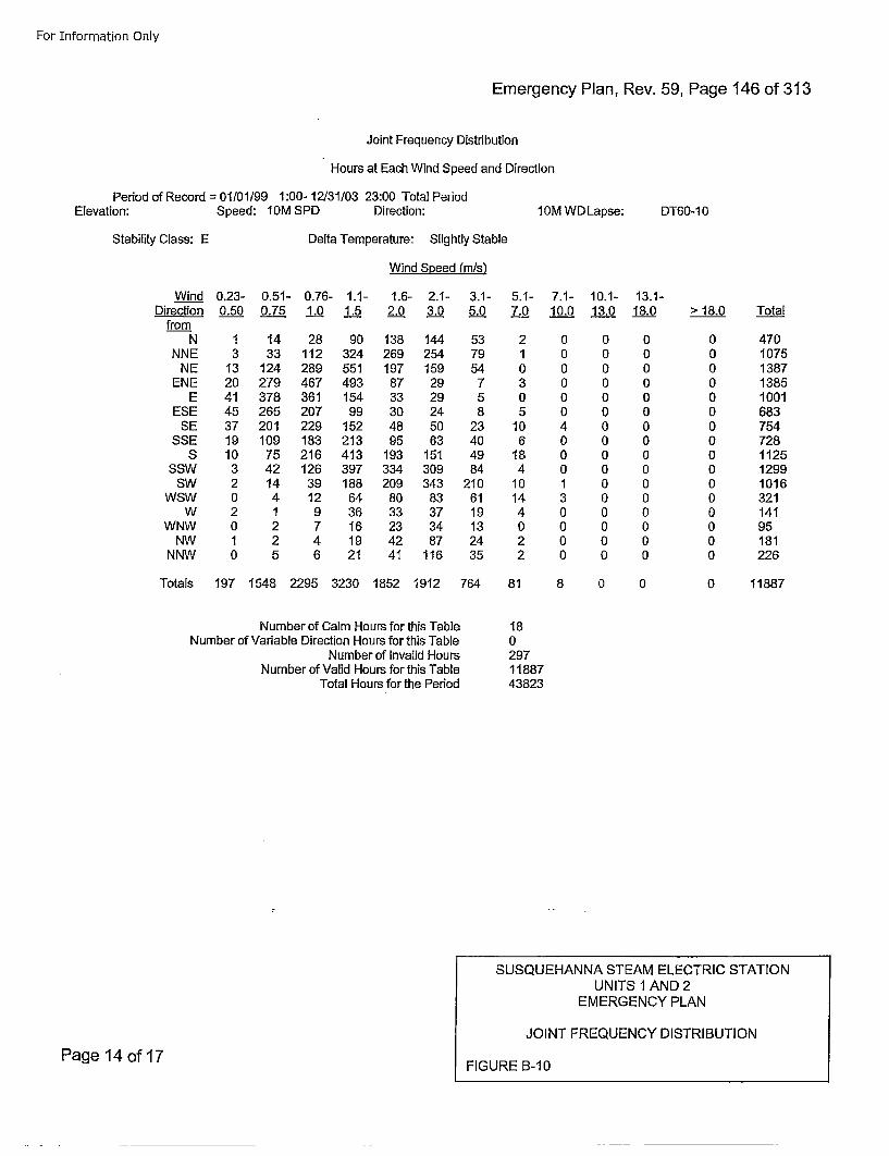
For Information Only
Emergency Plan, Rev. 59, Page 146 of 313
Joint Frequency Distribution
Hours at Each Wind Speed and Direction
Period of Record =01/01/99 1:00- 12131/03 23:00 Total PeriodElevation: Speed: 1DM SPD Direction: 10M WDLapse: DT60-1 0
Stability Class: E Delta Temperature: Slightly Stable
Wind Speed (m/s)
Wind 0.23- 0.51- 0.76- 1.1- 1.6- 2.1- 3.1- 5.1- 7.1- 10.1- 13.1-Direction 0.50 0.75 1.0 1.5 2.0 3.0 5.0 7.0 10.0 13.0 18.0
from.N 1 14 28 90 138 144 53 2 0 0 0
NNE 3 33 112 324 269 254 79 1 0 0 0NE 13 124 289 551 197 159 54 0 0 0 0
ENE 20 279 467 493 87 29 7 3 0 0 0E 41 378 361 154 33 29 5 0 0 0 0
ESE 45 265 207 99 30 24 8 5 0 0 0SE 37 201 229 152 48 50 23 10 4 0 0
SSE 19 109 183 213 95 63 40 6 0 0 0S 10 75 216 413 193 151 49 18 0 0 0
SSW 3 42 126 397 334 309 84 4 0 0 0SW 2 14 39 188 209 343 210 10 1 0 0
WSW 0 4 12 64 80 83 61 14 3 0 0W 2 1 9 36 33 37 19 4 0 0 0
WNW 0 2 7 16 23 34 13 0 0 0 0NW 1 2 4 19 42 87 24 2 0 0 0
NNW 0 5 6 21 41 116 35 2 0 0 0
> 18.0 Total
0000000000000000
470107513871385100168375472811251299101632114195181226
Totals 197 1548 2295 3230 1852 1912 764
Number of Calm Hours for this TableNumber of Variable Direction Hours for this Table
Number of Invalid HoursN umber of Valid Hours for this Table
Total Hours for the Period
81 8 0 0 0 11887
1802971188743823
SUSQUEHAN NA STEAM ELECTRIC STATIONUNITS 1 AND 2
EMERGENCY PLAN
JOINT FREQUENCY DISTRIBUTION
Page 14 of 17FIGURE B-10
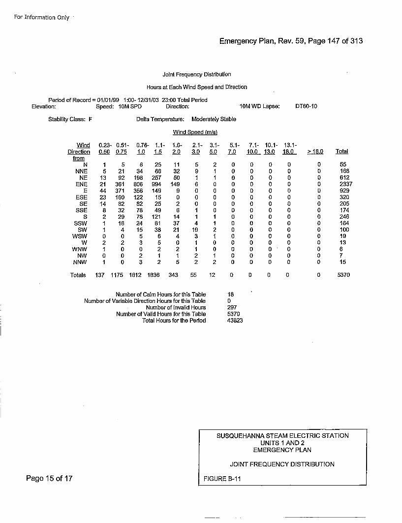
For Information Only•
Emergency Plan, Rev. 59, Page 147 of 313
Joint Frequency Distribution
Hours at Each Wind Speed and Direction
Period of Record =01/01199 1:00- 12/31/03 23:00 Total PeriodElevation: Speed: 10M SPD Direction: 10M WD Lapse: DT60-10
Stability Class: F Delta Temperature: Moderately Stable
Wind Speed (mis)
Wind 0.23- 0.51- 0.76- 1.1- 1.6- 2.1- 3.1- 5.1- 7.1- 10.1- 13.1-Direction 0.50 0.75 1.0 1.5 2.0 3._0 5._0 7.0 10.0 13.0 18.0
fromN 1 5 6 25 11 5 2 0 0 0 0
NNE 5 21 34 66 32 9 1 0 0 0 0NE 13 92 198 257 50 1 1 0 0 0 0
ENE 21 361 806 994 149 6 0 0 0 0 0E 44 371 356 149 9 0 0 0 0 0 0
ESE 23 160 122 15 0 0 0 0 0 0 0SE 14 82 82 25 2 0 0 0 0 0 0
SSE 8 32 78 49 6 1 0 0 0 0 0S 2 29 78 121 14 1 1 0 0 0 0
SSW 1 16 24 81 37 4 1 0 0 0 0SW 1 4 15 38 21 19 2 0 0 0 0
WSW 0 0 5 6 4 3 1 0 0 0 0W 2 2 3 5 0 1 0 0 0 0 0
WNW 1 0 0 2 2 1 0 0 0 0 0NW 0 0 2 1 1 2 1 0 0 0 0
NNW 1 0 3 2 5 2 2 0 0 0 0
> 18.0 Total
0000000000000000
55168612233792932020517424616410019136715
Totals 137 1175 1812 1836 343 55 12
Number of Calm Hours for this TableNumber of Variable Direction Hours for this Table
Number of Invalid HoursNumber of Valid Hours for this Table
Total Hours for the Period
0 0 0 0 0 5370
180297537043823
SUSQU EHANNA STEAM ELECTRIC STATIONUNITS I AND 2
EMERGENCY PLAN
JOINT FREQUENCY DISTRIBUTION
FIGURE B-ilPage 15 of 17
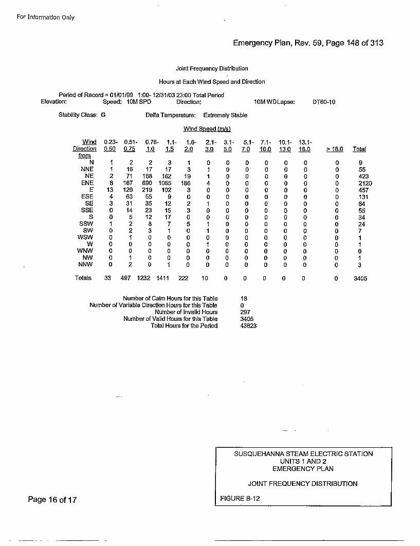
For Information Only
Emergency Plan, Rev. 59, Page 148 of 313
Joint Frequency Distribution
Hours at Each Wind Speed and Direction
Period of Record = 01/01/99 1:00- 12/31/03 23:00 Total PeriodElevation: Speed: I0M SPD Direction:l0M WD Lapse: DT60-1 0
Stability Class: G Delta Temperature: Extremely Stable
Wind Speed (mis)
Wind 0.23- 0.51- 0.76- 1.1- 1.6- 2.1- 3.1- 5.1- 7.1- 10.1- 13.1-Direction 0.50 0.75 1.0 1._.5 2._0 3.0 5.0 7.0 10.0 13.0 18.0
fromN 1 2 2 3 1 0 0 0 0 0 0
NNE 1 16 17 17 3 1 0 0 0 0 0NE 2 71 168 162 19 1 0 0 0 0 0
ENE 8 167 690 1065 186 4 0 0 0 0 0E 13 120 219 102 3 0 0 0 0 0 0
ESE 4 63 55 9 0 0 0 0 0 0 0SE 3 31 35 12 2 1 0 0 0 0 0
SSE 0 14 23 15 3 0 0 0 0 0 05 0 5 12 17 0 0 0 0 0 0 0
SSW 1 2 8 7 5 1 0 0 0 0 0SW 0 2 3 1 0 1 0 0 0 0 0
WSW 0 1 0 0 0 0 0 0 0 0 0W 0 0 0 0 0 1 0 0 0 0 0
WNW 0 0 0 0 0 0 0 0 0 0 0NW 0 1 0 0 0 0 0 0 0 0 0
NNW 0 2 0 1 0 0 0 0 0 0 0
> 18.0 Total
0000000000000000
95542321204571318455342471I0I3
Totals 33 497 1232 1411 222 10
Number of Calm Hours for this TableNumber of Variable Direction Hours for this Table
Number of Invalid HoursN umber of Valid Hours for this Table
Total Hours for the Period
0 0 0 0 0
180297340543823
0 3405
SUSQUEHANNA STEAM ELECTRIC STATIONUNITS I AND 2
EMERGENCY PLAN
JOINT FREQUENCY DISTRIBUTION
FIGURE B-12Page 16 of 17
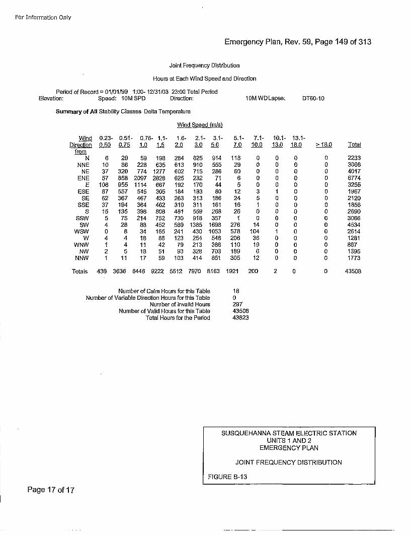
For Information Only
Emergency Plan, Rev. 59, Page 149 of 313
Joint Frequency Distribution
Hours at Each Wind Speed and Direction
Period of Record = 01/01199 1:00- 12131103 23:00 Total PeriodElevation: Speed: I0M SPD Direction:
Summary of All Stability Classes Delta Temperature
Wind Speed (msls
10M WD Lapse: DT60-1 0
Wind 0.23- 0.51- 0.76- 1.1- 1.6- 2.1- 3.1- 5.1- 7.1- 10.1- 13.1-Direction 0.50 0.75 1.0 1.5 2.0 3.0 5.0 7.0 10.0 13.0 18.0
fromN 6 29 59 198 284 625 914 118 0 0 0
NNE 10 86 228 635 613 910 555 29 0 0 0NE 37 320 774 1277 602 715 286 60 0 0 0
ENE 57 858 2097 2828 625 232 71 6 0 0 0E 108 955 1114 667 192 170 44 5 0 0 0
ESE 87 557 545 305 184 193 80 12 3 1 0SE 62 367 467 433 263 313 186 24 5 0 0
SSE 37 194 364 462 310 311 161 16 1 0 0S 15 135 398 808 481 559 268 26 0 0 0
SSW 5 75 214 752 730 918 357 1 0 0 0SW 4 28 88 452 589 1385 1698 276 14 0 0
WSW 0 8 34 165 241 430 1053 578 104 1 0W 4 4 18 88 123 254 548 206 36 0 0
WNW 1 4 11 42 79 213 388 110 19 0 0NW 2 5 18 51 93 328 703 189 6 0 0
NNW 1 11 17 59 103 414 851 305 12 0 0
> 18,0 Total
0000000000000000
223330664017677432551967212018562690306645342614128186713951773
Totals 436 3636 6446 9222 5512 7970 8163
Number of Calm Hours for this TableNumber of Variable Direction Hours for this Table
Number of Invalid HoursNumber of Valid Hours for this Table
Total Hours for the Period
1921 200 2 0 0 43508
1802974350843823
SUSQU EHAN NA STEAM ELECTRIC STATIONUNITS 1 AND 2
EMERGENCY PLAN
JOINT FREQUENCY DISTRIBUTION
FIGURE B-13
Page 17 of 17
For Information Only
EmerencyPlan Rev 59,Page150 IfI31
APPENDIX C
SSES EMERGENCY PLAN
POSITION SPECIFIC PROCEDURES
(TYPICAL)
Page 1 of 2
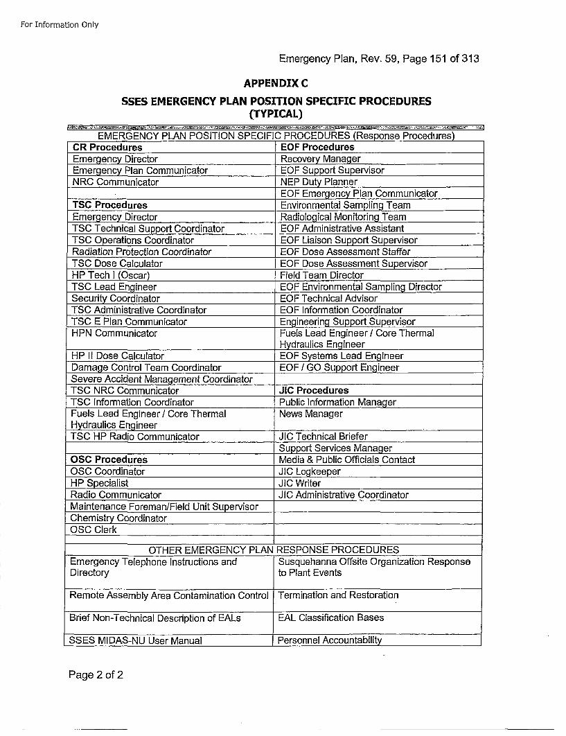
For Information Only
Emergency Plan, Rev. 59, Page 151 of 313
APPENDIX C
SSES EMERGENCY PLAN POSITION SPECIFIC PROCEDURES(TYPICAL)
EMERGENCY PLAN POSITION SPECIFIC PROCEDURES (Response Procedures)CR Procedures EOF ProceduresEmergency Director Recovery ManagerEmergency Plan Communicator EOF Support SupervisorNRC Communicator NEP Duty Planner
EOF Emergency Plan CommunicatorTSC Procedures Environmental Sampling TeamEmergency Director Radiological Monitoring TeamTSC Technical Support Coordinator EOF Administrative AssistantTSC Operations Coordinator EOF Liaison Support SupervisorRadiation Protection Coordinator EOF Dose Assessment StafferTSC Dose Calculator EOF Dose Assessment SupervisorHP Tech I (Oscar) Field Team DirectorTSC Lead Engineer EOF Environmental Sampling DirectorSecurity Coordinator EOF Technical AdvisorTSC Administrative Coordinator EOF Information CoordinatorTSC E Plan Communicator Engineering Support SupervisorHPN Communicator Fuels Lead Engineer / Core Thermal
________________________________Hydraulics EngineerHP I1 Dose Calculator EOF Systems Lead EngineerDamage Control Team Coordinator EOF / GO Support EngineerSevere Accident Management CoordinatorTSC NRC Communicator JIC ProceduresTSC Information Coordinator Public Information ManagerFuels Lead Engineer I Core Thermal News ManagerHydraulics EngineerTSC HP Radio Communicator JIC Technical Briefer
Support Services ManagerOSC Procedures Media & Public Officials Contact0S0 Coordinator JIG LogkeeperHP Specialist JIC WriterRadio Communicator J IC Administrative CoordinatorMaintenance Foreman/Field Unit SupervisorChemistry Coordinator ____________________OSC Clerk
OTHER EMERGENCY PLAN RESPONSE PROCEDURESEmergency Telephone Instructions and Susquehanna Offsite Organization ResponseDirectory to Plant Events
Remote Assembly Area Contamination Control Termination and Restoration
Brief Non-Technical Description of EALs EAL Classification Bases
SSES MIDAS-NU User Manual Personnel Accountability
Page 2 of 2
For Information Only
Emergency Plan, Rev. 59, Page 152 of 313
APPENDIX D
EQUIPMENT INFORMATION LISTINGS
I II
Page 1 ofl16
For Information Only
Enclosure 1
Enclosure 2
Enclosure 3
Enclosure 4
Enclosure 5
Enclosure 6
Enclosure 7
Enclosure 8
Enclosure 9
Emergency Plan, Rev. 59, Page 153 of 313
CONTENTS OF APPENDIX D
Equipment Information Listinqs
Typical Station Decontamination Area EquipmentTypical Damage Control Equipment Storage Box Contents
Onsite Search and Rescue/First Add, Typical Ambulance and Hospital RadiationEmergency Equipment and Supplies
Natural Phenomena Monitors
Radiological Monitors
Environmental Monitoring Systems
Typical Health Physics Van Radiation Emergency Monitoring Equipment
Emergency Classification Dependent Instrumentation
Typical Initial Emergency Equipment for Initial Incident Response
Typical TSC Equipment
Typical EOF Equipment
Page 2 of 16
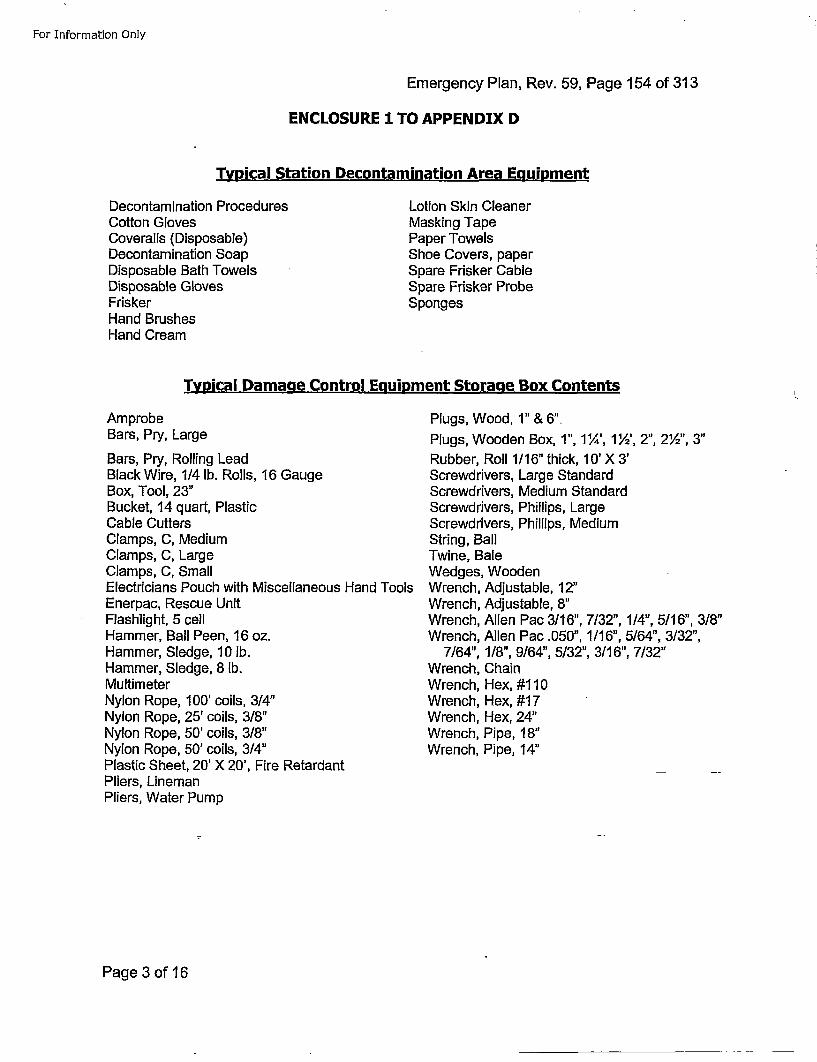
For Information Only
Emergency Plan, Rev. 59, Page 154 of 313
ENCLOSURE 1 TO APPENDIX D
Typical Station Decontamination Area Ecluipment
Decontamination ProceduresCotton GlovesCoveralls (Disposable)Decontamination SoapDisposable Bath TowelsDisposable GlovesFriskerHand BrushesHand Cream
Lotion Skin CleanerMasking TapePaper TowelsShoe Covers, paperSpare Frisker CableSpare Frisker ProbeSponges
Typical Damaae Control Equipment Storaqe Box Contents
AmprobeBars, Pry, Large
Bars, Pry, Rolling LeadBlack Wire, 114 lb. Rolls, 16 GaugeBox, Tool, 23"Bucket, 14 quart, PlasticCable CuttersClamps, C, MediumClamps, C, LargeClamps, C, SmallElectricians Pouch with Miscellaneous Hand ToolsEnerpac, Rescue UnitFlashlight, 5 cellHammer, Ball Peen, 16 oz.Hammer, Sledge, 10 lb.Hammer, Sledge, 8 lb.MultimeterNylon Rope, 100' coils, 3/4"Nylon Rope, 25' coils, 3/8"Nylon Rope, 50' coils, 3/8"Nylon Rope, 50' coils, 3/4"Plastic Sheet, 20' X 20', Fire RetardantPliers, LinemanPliers, Water Pump
Plugs, Wood, 1" & 6".Plugs, Wooden Box, 1", 1%', 1½', 2", 2',", 3"Rubber, Roll 1/16" thick, 10' X 3'Screwdrivers, Large StandardScrewdrivers, Medium StandardScrewdrivers, Phillips, LargeScrewdrivers, Phillips, MediumString, BallTwine, BaleWedges, WoodenWrench, Adjustable, 12"Wrench, Adjustable, 8"Wrench, Allen Pac 3116", 7/32", 1/4", 5/16", 318"Wrench, Allen Pac .050", 1/16", 5/64", 3/32",
7/64", 1/8", 9164", 5/32", 3116", 7/32"Wrench, ChainWrench, Hex, #110Wrench, Hex, #17Wrench, Hex, 24"Wrench, Pipe, 18"Wrench, Pipe, 14"
Page 3 of 16
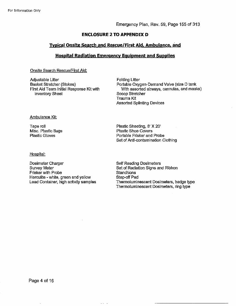
For Information Only
Emergency Plan, Rev. 59, Page 155 of 313
ENCLOSURE 2 TO APPENDIX D
Typical Onsite Search and Rescue/First Aid. Ambulance, and
Hospital Radiation Emergency Equipment and Supplies
Onsite Search Rescue/First Aid:
Adjustable LitterBasket Stretcher (Stokes)First Aid Team Initial Response Kit with
Inventory Sheet
Folding LifterPortable Oxygen-Demand Valve (size D tank
With assorted airways, cannulas, and masks)Scoop StretcherTrauma KitAssorted Splinting Devices
Ambulance Kit:
Tape rollMisc. Plastic BagsPlastic Gloves
Plastic Sheeting, 8' X 20'Plastic Shoe CoversPortable Frisker and ProbeSet of Anti-contamination Clothing
Hospital:
Dosimeter ChargerSurvey MeterFrisker with ProbeHerculite - white, green and yellowLead Container, high activity samples
Self Reading DosimetersSet of Radiation Signs and RibbonStan chionsStep-off PadThermoluminescent Dosimeters, badge typeThermoluminescent Dosimeters, ring type
Page 4 of 16
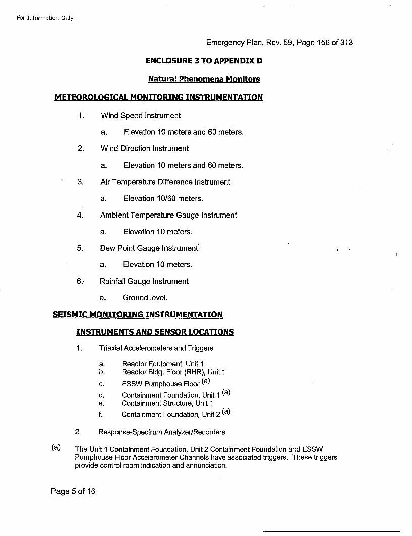
For Information Only
EmergencyPlan, Rev. 59, Page 156 of 313
ENCLOSURE 3 TO APPENDIX D
Natural Phenomena Monitors
METEOROLOGICAL MONITORING INSTRUMENTATION
1. Wind Speed Instrument
a. Elevation 10 meters and 60 meters.
2. Wind Direction Instrument
a. Elevation 10 meters and 60 meters.
3. Air Temperature Difference Instrument
a. Elevation 10160 meters.
4. Ambient Temperature Gauge Instrument
a. Elevation 10 meters.
5. Dew Point Gauge Instrument
a. Elevation 10 meters.
6.: Rainfall Gauge Instrument
a. Ground level.
SEISMIC MONITORING INSTRUMENTATION
INSTRUMENTS AND SENSOR LOCATIONS
1. Triaxial Accelerometers and Triggers
a. Reactor Equipment, Unit 1b. Reactor Bldg. Floor (RHR), Unit 1c. ESSW Pumphouse Floor (a)
d. Containment Foundation, Unit 1 (a)e. Containment Structure, Unit 1f. Containment Foundation, Unit 2 (a)
2 Response-Spectrum Analyzer/Recorders
(a) The Unit 1 Containment Foundation, Unit 2 Containment Foundation and ESSWPumphouse Floor Accelerometer Channels have associated triggers. These triggersprovide control room indication and annunciation.
Page 5 of 16
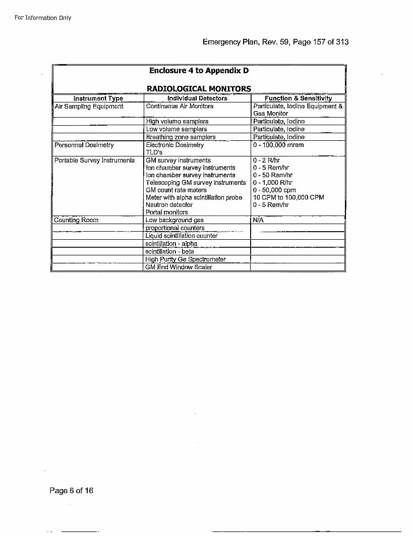
For Information Only
Emergency Plan, Rev. 59, Page 157 of 313
Enclosure 4 to Appendix D[ RADIOLOGICAL MONITORSInstrument Type Individual Detectors Function & Sensitivi.t
Air Sampling Equipment !Continuous Air Monitors Particulate, Iodine Equipment &Gas Monitor
High volume samplers Particulate, IodineLow volume samplers P~articulate, IodineBreathing zone samplers Particulate, Iodine
Personnel Dosimetry Electronic Dosimetry 0- 100,000 mremTLD's
Portable Survey Instruments GM survey instruments 0 - 2 R/hrIon chamber survey instruments 0 - 5 Rem/hrIon chamber survey instruments 0 - 50 Rem/hrTelescoping GM survey instruments 0 - 1,000 R/hrGM count rate meters 0 - 50,000 cpmMeter with alpha scintillation probe 10 CPM to 100,000 CPMNeutron detector 0 - 5 Rem/hrPortal monitors______________
Counting Room Low background gas N/A_____________________proportional counters
Liquid scintillation counterscintillation - apha .. _____________
_______________________ scintillation - beta ______________
_____________________High Purity Ge Spectrometer__________________________________GM End Window Scaler
Page 6 of 16
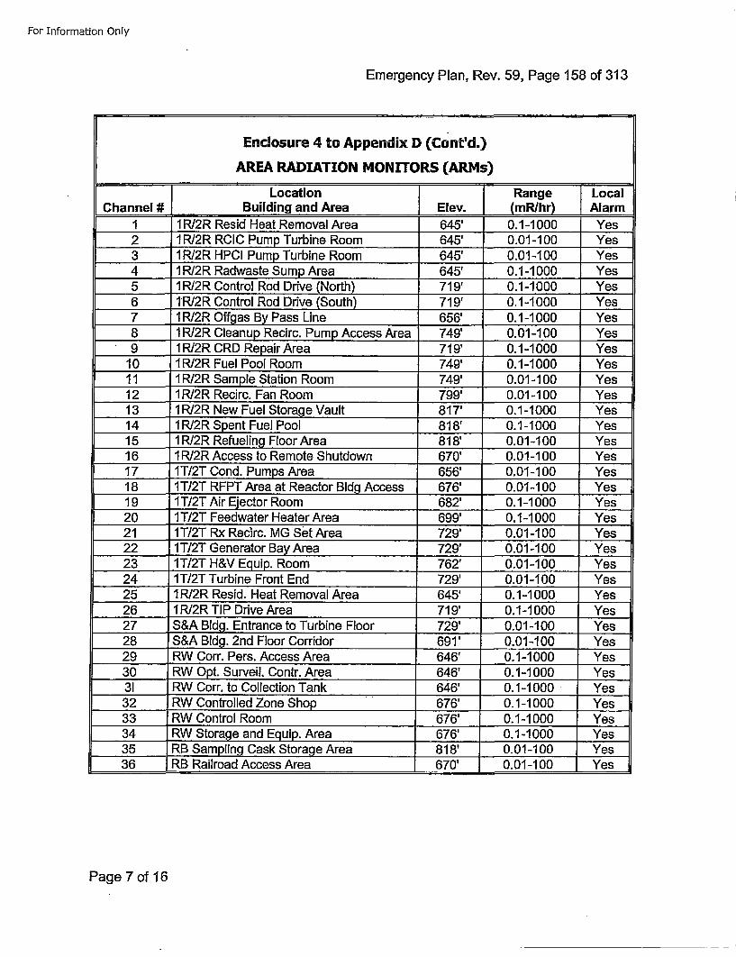
For Information Only
Emergency Plan, Rev. 59, Page 158 of 313
Enclosure 4 to Appendix D (Cont'd.)
AREA RADIATION MONITORS (ARMs)
1Location j Range LocalChannel #J Building and Area j Elev. (mR/hr) JAlarm
1 1RI2R Resid Heat Removal Area 645' 0.1-1000 Yes2 1R/2R RCIC Pump Turbine Room 645' 0.01-100 Yes3 1R/2R HPCI Pump Turbine Room 645' 0.01-1 00 Yes4 1 R/2R Radwaste Sump Area 645' 0.1-1 000 .. Yes5 1RI2R Control Rod Drive (North) 719' 0.1-1 000 Yes6 1RJ2R Control Rod Drive (South) 719' 0.1-1'000 Yes7 1 RI2R Offgas By Pass Line 656' 0.1-1 000 Yes8 1RI2R Cleanup Recirc. Pump Access Area 749' 0.01-100 Yes9 1RI2R CRD Repair Area 719' 0.1-1000 Yes
10 1RI2R Fuel Pool Room 749' 0.1-1000 Yes11 1 RI2R Sample Station Room 749' 0.01-100 Yes12 1RI2R Recirc. Fan Room 799' 0.01-1 00 Yes13_ 1R/2R New Fuel Storage Vault 817' 0.1-1000 Yes
14 1R/2R Spent Fuel Pool 818' 0.1-1000 Yes15 1R/2R Refueling Floor Area 818' 0.01-1 00 Yes16 1R/2R Access to Remote Shutdown 670' 0.01-1 00 Yes17 1T/2T Cond. Pumps Area 656' 0.01-100 Yes18 1IT/2T RFPT Area at Reactor Bldg Access 676' 0.01-100 Yes19 1 T/2T Air Ejector Room 682' 0.1-1000 Yes20 1T/2T Feedwater Heater Area 699' 0.1-1000 Yes21 1T/2T Rx Recirc. MG set Area 729' 0.01-1 00 Yes22 1T/2T Generator Bay Area 729' 0.01-1 00 Yes23 1T/2T H&V Equip. Room 762' 0.01-100 Yes24 1T/2T Turbine Front End 729' 0.01-1 00 Yes25 1RI2R Resid. Heat Removal Area 645' 0.1-1 000 Yes26 1R/2R TIP Drive Area 719' 0.1-1000 Yes27 S&A Bldg. Entrance to Turbine Floor 729' 0.01-1 00 Yes28 S&A Bldg. 2nd Floor Corridor 691' 0.01-100 Yes29 RW Corr. Pers. Access Area 646' 0.1-1 000 Yes30 RW Opt. Surveil. Contr. Area 646' 0.1-1 000 Yes31 RW Corr. to Collection Tank 646' 0.1-1 000 Yes32 RW Controlled Zone Shop "676' 0.1-1000 Yes33 RW Control Room 676' 0.1-1000 Yes34 RW Storage and Equip. Area 676' 0.1-1000 Yes35 .RB Sampling Cask Storage Area 818' 0.01-1 00 Yes36 RB Railroad Access Area 670' 0.01-1 00 Yes
Page 7 of 16
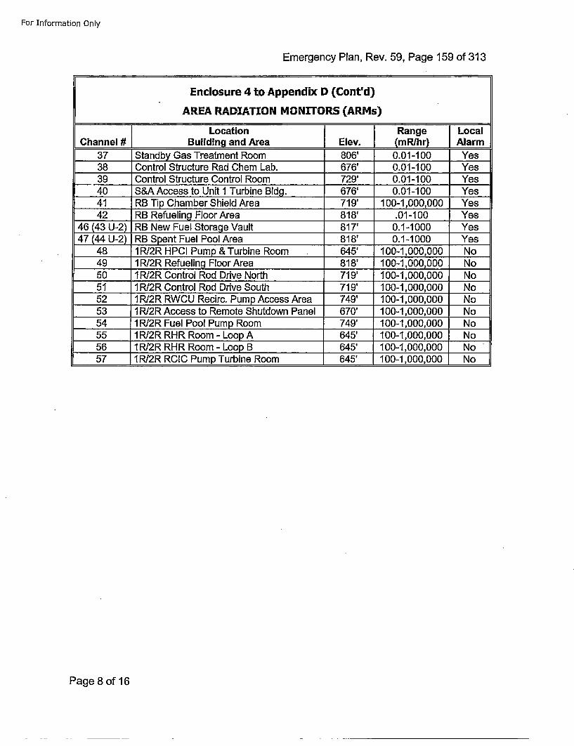
For Information Only
Emergency Plan, Rev. 59, Page 159 of 313
Enclosure 4 to Appendix D (Cont'd)
AREA RADIATION MONITORS (ARMs)
ILocation JRange LocalChannel # Building and Area jElev. (mRhr)~ Alarm
37 Standby Gas Treatment Room 806' 0.01-1 00 Yes38 Control Structure Rad Chem Lab. 676' 0.01-100 Yes39 Control Structure Control Room 729' 0.01-1 00 Yes40 S&A Access to Unit I Turbine Bldg. 676' 0.01-1 00 Yes41 RB Tip Chamber Shield Area 719' 100-1,000,000 Yes42 RB Refueling Floor Area 818' .01-1 00 Yes
46 (43 U-2) RB New Fuel Storage Vault 817' 0.1-1 000 Yes47 (44 U-2) RB Spent Fuel Pool Area 818' 0.1-1 000 Yes
48 RIR2R HPCI Pump & Turbine Room 645' 100-1,000,000 No49 1RI2R Refueling Floor Area 818' 100-1,000,000 No50 1 RI2R Control Rod Drive North 719' 100-1,000,000 No51 iPJ2R Control Rod Drive South 719' 100-1,000,000 No52 1R/2R RWCU Recirc. Pump Access Area 749' 100-1,000,000 No53 1PRJ2R Access to Remote Shutdown Panel 670' 100-1,000,000 No54 1R/2R Fuel Pool Pump Room 749' 100-1,000,000 No55 1 RI2R RHR Room - Loop A 645' 100-1,000,000 No56 1 RI2R RHR Room - Loop B 645' 100-1,000,000 No57 1RI2R RCIC Pump Turbine Room 645' 100-1,000,000 No
Page 8 of 16
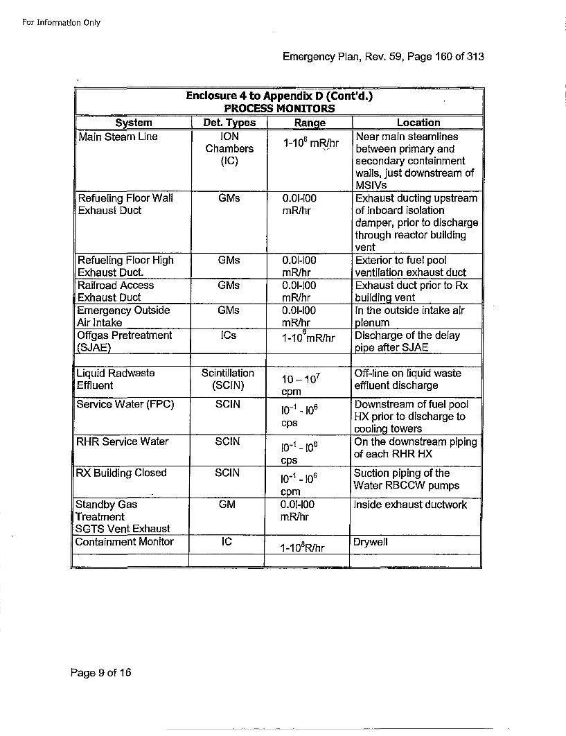
For Inforrnat~on Only
Emergency Plan, Rev. 59, Page 160 of 313
Enclosure 4 to Appendix D (Cont'd.,)PROCESS MvONIrTORS
[ System Det.ypes[ Range [LocationMainSChambersIO 1-106 mR/hr Near main steamlines
Chambrs • between primary and(IC) secondary containment
walls, just downstream ofMSIVs
Refueling Floor Wall GMs 0.01-100 Exhaust ducting upstreamExhaust Duct mRlhr of inboard isolation
damper, prior to dischargethrough reactor building
____ ___ ___ ___ ___ ___ ___ ___vent
Refueling Floor High GMs 0.01-100 Exterior to fuel poolExhaust Duct. mR/hr ventilation exhaust ductRailroad Access GMs 0.01-100 Exhaust duct prior to RxExhaust Duct mR/hr building ventEmergency Outside GMs 0.01-100 In the outside intake airAir Intake mR/hr plenumOffgas Pretreatment ICs 1-10ObmR/hr Discharge of the delay(SJAE) ______ ______pipe after SJAE
Liquid Radwaste Scintillation 10 - 07 Off-line on liquid wasteEffluent (SClN) effluent discharge
_________ cpm _ _ _ _ _ _ _ _Service Water (FPC) SClN 10_1.106 Downstream of fuel pool
HX prior to discharge tocps cooling towers
RHR Service Water SClN l10_ 106 On the downstream pipingof each RHR HXcps__ _ _ _ _ _ _ _ _ _ _
RX Building Closed SClN 10_1.-106 Suction piping of theWater RBCCW pumps
_____ cpmStandby Gas GM 0.01-100 Inside exhaust ductworkTreatment mR/hrSGTS Vent ExhaustContainment Monitor IC 1-108 R/hr Drywell
Page 9 of 16
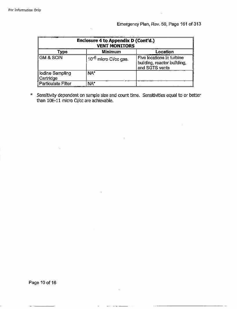
For Information Only
Emergency Plan, Rev. 59, Page 161 of 313
Enclosure 4 to Appendix D (Cont'd..)_____________ VENT MONITORS-_ ________
IType ] Minimum [LocationGM & SCIN 10-6 micro Ci/oc gas. Five locations in turbine
building, reactor building,________________and SGTS vents
Iodine Sampling NA*Cartridge____________Particulate Filter NA*
* Sensitivity dependent on sample size and count time. Sensitivities equal to or betterthan 10E-11 micro Ci/cc are achievable.
Page 10 of 16
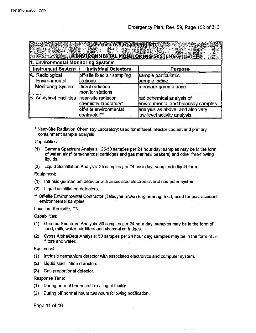
For Information Only
Emergency Plan, Rev. 59, Page 162 of 313
':~~~~~~~~~~~~~.............• •., . ..••:.:"•,-:t-."-•,°' . -;....."•:•Z :•!.
[i. Environmental Monitoring SystemsInstrument System Individual Detectors Purpose,.Radiological off-site fixed air sampling sample particulates
Environmental •tations •ample iodineMonitoring System dlirect radiation measure gamma dose
________________ onitor stations_________________B. Analytical Facilities near-site radiation radiochemical analysis of
chemistry laboratory* environmental and bioassay samplesoff-site environmental analysis as above, and also verycontractor** low-level' activity analysis
* Near-Site Radiation Chemistry Laboratory; used for effluent, reactor coolant and primarycontainment sample analysis..
Capabilities:
(1) Gamma Spectrum Analysis: 25-50 samples per 24 hour day; samples may be in the formof water, air (filters/charcoal cartridges and gas marinelli beakers) and other free-flowingliquids.
(2) Liquid Scintillation Analysis: 25 samples per 24 hour day; samples in liquid form.
Equipment:
(1) Intrinsic germanium detector with associated electronics and computer system.
(2) Liquid scintillation detectors.
** Off-site Environmental Contractor (Teledyne Brown Engineering, Inc.); used for post-accidentenvironmental samples
Location: Knoxville, TN.
Capabilities:
(1) Gamma Spectrum Analysis: 50 samples per 24 hour day; samples may be in the form offood, milk, water, air filters and charcoal cartridges.
(2) Gross Alpha/Beta Analysis: 50 samples per 24 hour day; samples may be in the form of airfilters and water.
Equipment:
(1) Intrinsic germanium detector with associated electronics and computer system.
(2) Liquid scintillation detectors.
(3) Gas proportional detector.
Response Time:
(1) During normal hours staff existing at facility.
(2) During off normal hours two hours following notification.
Page 11 of 16
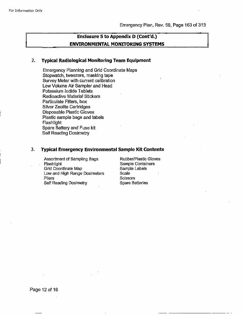
For Information Only
Emergency Plan, Rev. 59, Page 163 of 313
II Enclosure 5 to Appendix D (Cont'd.)ENVIRONMENTAL MONITORING SYSTEMS
2. Typical Radiological Monitoring Team Equipment
Emergency Planning and Grid Coordinate MapsStopwatch, tweezers, masking tapeSurvey Meter with current calibrationLow Volume Air Sampler and HeadPotassium Iodide TabletsRadioactive Material StickersParticulate Filters, boxSilver Zeolite CartridgesDisposable Plastic GlovesPlastic sample bags and labelsFlashlightSpare Battery and Fuse kitSelf Reading Dosimetry
3. Typical Emergency Environmental Sample Kit Contents
Assortment of Sampling BagsFlashlightGrid Coordinate MapLow and High Range DosimetersPliersSelf Reading Dosimetry
RubberlPlastic GlovesSample ContainersSample LabelsScaleScissorsSpare Batteries
Page 12 of 16
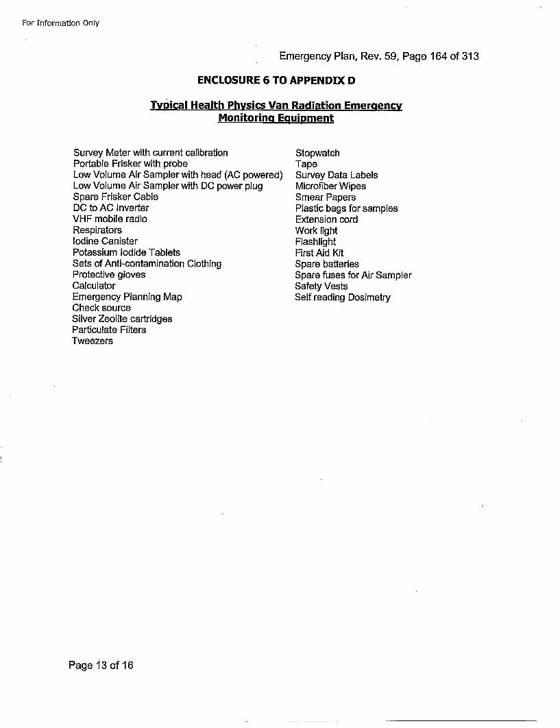
For Information Only
Emergency Plan, Rev. 59, Page 164 of 313
ENCLOSURE 6 TO APPENDIX D
Typical Health Physics Van Radiation EmeraencvMonitoring Epuipment
Survey Meter with current calibrationPortable Frisker with probeLow Volume Air Sampler with head (AC powered)Low Volume Air Sampler with DC power plugSpare Frisker CableDC to AC InverterVHF mobile radioRespiratorsIodine CanisterPotassium Iodide TabletsSets of Anti-contamination ClothingProtective glovesCalculatorEmergency Planning MapCheck sourceSilver Zeolite cartridgesParticulate FiltersTweezers
StopwatchTapeSurvey Data LabelsMicrofiber WipesSmear PapersPlastic bags for samplesExtension cordWork lightFlashlightFirst Aid KitSpare batteriesSpare fuses for Air SamplerSafety VestsSelf reading Dosimetry
Page 13 of 16
For Information Only
Emergency Plan, Rev. 59, Page 165 of 313
ENCLOSURE 7 TO APPENDIX D
Erneraencv Classification Dependent Instrumentation
Vent Stack MonitorsMeteorological Tower IndicationRemote Monitoring SystemAirborne Sampling SystemLiquid Radwaste SamplingLiquid Discharge Radiation MonitorsSpent Fuel Pool Level IndicationArea Radiation MonitorsPrimary Containment Isolation Valve Position IndicationReactor Coolant System SamplingReactor Pressure Vessel Level Indication (Fuel Zone, Shutdown Range, Extended WideRange)Main Steam Isolation Valve Position IndicationMain Steam Line Flow IndicationMain Steam Line Tunnel Temperature IndicationDrywell Sump Level IndicationReactor Building Temperature IndicationContainment Pressure IndicationContainment Hydrogen / Oxygen AnalyzersContainment High Range Radiation MonitorAC Power - 13.8KV (Downstream Loads / Breaker Position)AC Power - 4KV (Downstream Loads I Breaker Position)125 VDC Power (Downstream Loads / Breaker Position)Nuclear Instrumentation (APRM, SRM)Suppression Pool Temperature IndicationSuppression Pool Level IndicationReactor Pressure Vessel Pressure IndicationDrywell Equipment Drain Tank Level IndicationOffgas Pretreatment Radiation MonitorSeismic Monitor InstrumentationStation Flooding InstrumentationSimplex Fire DetectionReactor Coolant System Temperature IndicationReactor Building Sump Level IndicationReactor Protection System Trip Indication
Page 14 of 16
For Information Only
Emergency Plan, Rev. 59, Page 166 of 313
ENCLOSURE 8 TO APPENDIX D
Typical Emergency Equipment for Initial Incident Response
Portable frisker with probeLow volume Air Sample with HeadHigh Volume Air Sampler with HeadSurvey MeterSpare frisker cable and probeParticulate filter paperSilver Zeolite CartridgesSpare Batteries and fusesPortable WorklightExtension CordSelf Reading Dosimetry*Potassium iodine TabletsAnti-contamination ClothingFull face RespiratorIodine Filter CanistersSCBA EquipmentEmergency PlanEmergency Plan Position Specific InstructionsEmergency Planning Map with offsite sampling locationsOnsite Monitoring Locations MapFirst Aid KitKeys to Health Physics VanEmergency Plan KeysFood and potable water adequate to support 10 people for 5 days.
*Available at OSC and at HP control point to the RCA.
Typical Technical Support Center Equipment
Plant Technical SpecificationsOperating Procedures ManualEmergency Operating Procedure ManualFinal Safety Analysis ReportEP and EP-PSsSafety Procedure ManualOffsite Dose Calculation ManualPlant as built drawingsEmergency Phone DirectoryCopy Machine and Telecopier
Page 15 of 16
For Information Only
Emergency Plan, Rev. 59, Page 167 of 313
ENCLOSURE 9 TO APPENDIX D
Typical Emerqency Operations Facility Equipment
Plant Technical SpecificationsOperating Procedures ManualEmergency Operating Procedures ManualFinal Safety Analysis ReportEmergency PlanEmergency Plan Position Specific InstructionsCurrent Emergency Plans for PEMA, LCEMA, CCEMARad Health HandbookOffsite Dose Calculation ManualEmergency Phone DirectoryEmergency Planning Map with Offsite Monitoring LocationsCalculatorsFlashlightFirst Aid Kit
Page 16 of 16
For Information Only
Emergency Plan, Rev. 59, Page 168 of 313
APPENDIX E
Susquehanna Nuclear, LLC Policy Statement:SUSQUEHANNA SES EMERGENCY MANAGEMENT
Page 1 of 2
For Information Only
Emergency Plan, Rev. 59, Page 169 of 313
TIfmothy. S. Raizsch 8usqziehanna Nucloar LLC
Be~w]ok, PA 18603 T ~ ~ -4TL'• 5,7..42.44 E NE RGY
T1motihn.Ra=uschTalenEnanwer, cm
July 17, 2015
SUJSQUEHANNA NUCLEAR LLC POLICY STATEMENT:
SUS.QUEH.A.NNA STEAM ELECTRIC STATION EMERGENCY MANAGEMENT
Immediate response, assessment, and tlhe implementalion of protective and corrective measures pertaining toan emergency condition at the Susquehanna Steam Electro Station shall be the responsibility of the SSESEmergency Director until relieved of this function by the Recovery Manager. The indMduals who shall act inthe capacity of S8ES Emergency Managers are determined as follows:
Immediately upon the occurrence of an emergency, the Shift Manager on dutyat the station shall assume the role of SSES Emergency Director, as described inthe SSES Emergency Plan, until relieved of that responsibility by the EmergencyDirector or his designated alternate.
If the emergency requires activation of the Emergency Operations Facility (EOF),the SSES Recovery Manager shall assume responsibility for overall managementof the emergency and off-site Protective Action Recommendations: The .SSESEmergency Director retains responsibility for on-site operations.
The SSES Emergency Managers shall implemnent applicable portions of the SSES Emergency Plan to preventor mitigate the consequences of emergencies at the Susquehanna Steam Electric Station. They shall have theauthority to act on behalf of Susquehanna Nuclear, LLC, in all matters concerning an emergency, at least untilsuch lime as the scope, severity, and potential radiological consequences have been assessed, and theappropriate protective and corrective actions have been implemented. Following that critical period, but stillwith complete regard for health and safety, major decisions and Corporate commitments are the responsibilityof Susquehanna Nuclear, LLC, Management.
Throughout the course of" an emergency condition, all expertise and support available within the SusquehannaNuclear, LLC organization shall be provided at the request of the SSES Emergency Managers,
Page 2 of 2
For Information Only
/J7"
Emergency Plan, Rev. 59, Page 170 of 313
APPENDIX F
DEVIATIONS TO NEI 99-01 REVE 4
Page 1 ofl13
For Information Only
Emergency Plan, Rev. 59, Page 171 of 313
Susquehanna Deviations to NEI 99-01 Rev 4INITIATING CONDITIONS and Emergency Actions Levels
This document contains a table listing all of the NEI INITIATING CONDITIONS along with acorrelation to the corresponding Susquehanna SES ICs. A description to any deviations from theNEI EALs is given.
Page 2 of 13
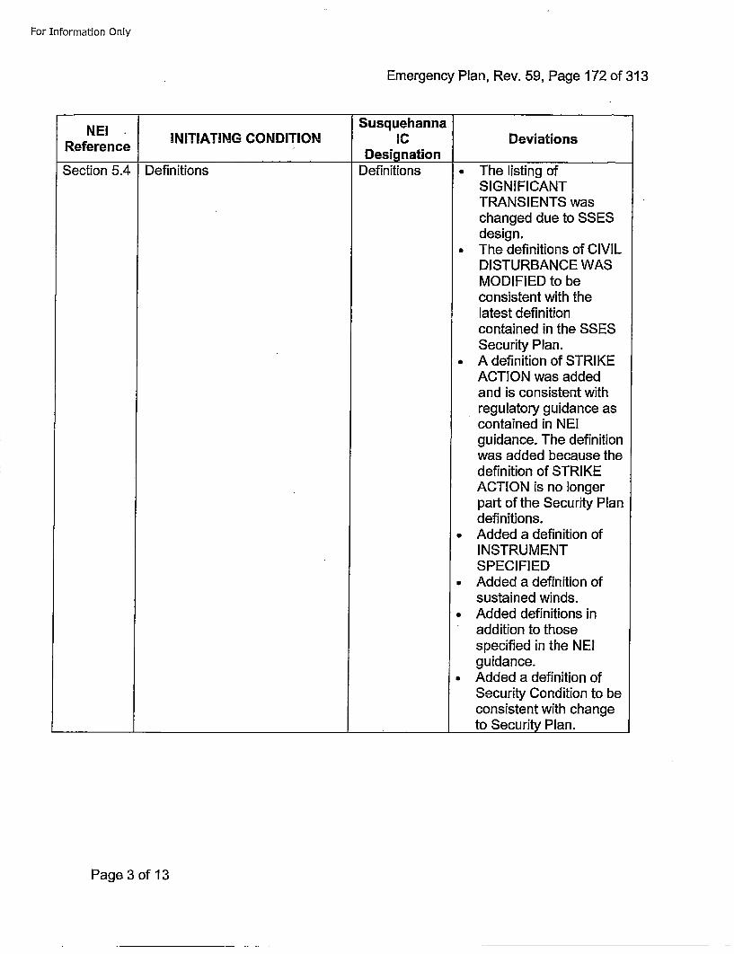
For Information Only
Emergency Plan, Rev. 59, Page 172 of 313
NEI SusquehannaRfrne INITIATING CONDITION IC Deviations
Reference _______________ Designation____________
Section 5.4 IDefinitions Definitions • The listing ofSIGNIFICANTTRANSIENTS waschanged due to SSESdesign.
• The definitions of CIVILDISTURBANCE WASMODIFIED to beconsistent with thelatest definitioncontained in the SSESSecurity Plan.
* A definition of STRIKEACTION was addedand is consistent withregulatory guidance ascontained in NEIguidance. The definitionwas added because thedefinition of STRIKEACTION is no longerpart of the Security Plandefinitions.
• Added a definition ofINSTRUMENTSPECIFIED
• Added a definition ofsustained winds.
* Added definitions in*addition to those
specified in the NEIguidance.
* Added a definition ofSecurity Condition to beconsistent with changeto Security Plan.
Page 3 of 13
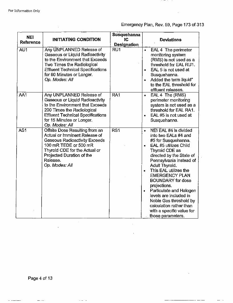
For Information Only
Emergency Plan, Rev. 59, Page 173 of 313
NEI SusquehannaRfrne INITIATING CONDITION IC Deviations
RfrneDesignation ___________
AU1 Any UNPLANNED Release of RU1 * EAL 4 The perimeterGaseous or Liquid Radioactivity monitoring systemto the Environment that Exceeds (RMS) is not used as aTwo Times the Radiological threshold for EAL RUI.Effluent Technical Specifications ° EAL 5 is not used atfor 60 Minutes or Longer. Susquehanna.Op. Modes: All ° Added the term liquid"
to the EAL threshold foreffluent releases.
AA1 Any UNPLANNED Release of RA1 • EAL 4 The (RMS)Gaseous or Liquid Radioactivity perimeter monitoringto the Environment that Exceeds system is not used as a200 Times the Radiological threshold for EAL RAI.Effluent Technical Specifications ° EAL #5 is not used atfor 15 Minutes or Longer. Susquehanna.Op. Modes: All
ASI Offsite Dose Resulting from an RSI ° NEI EAL #4 is dividedActual or Imminent Release of into two EALs #4 andGaseous Radioactivity Exceeds #5 for Susquehanna.100 mR TEDE or 500 mR ° EAL #5 utilizes ChildThyroid CDE for the Actual or Thyroid CDE asProjected Duration of the directed by the State ofRelease. Pennsylvania instead ofOp. Modes: All Adult Thyroid.
* This EAL utilizes theEMERGENCY PLANBOUNDARY for doseprojections.
* Particulate and Halogenlevels are included inNoble Gas threshold bycalculation rather thanwith a specific value for
________ ______________________ __________ those parameters.
Page 4 of 13
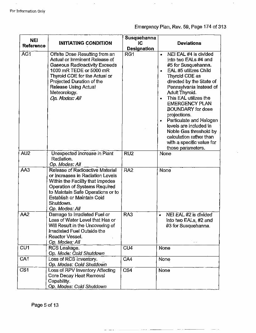
For Information Only
Emergency Plan, Rev. 59, Page 174 of 313
NEI SusquehannaRfrne INITIATING CONDITION IC DeviationsRefeenceDesignation
AGI Offsite Dose Resulting from an RG1 • NEI EAL #4 is dividedActual or Imminent Release of into two EALs #4 andGaseous Radioactivity Exceeds #5 for Susquehanna.1000 mR TEDE or 5000 mR • EAL #5 utilizes ChildThyroid CDE for the Actual or Thyroid CDE asProjected Duration of the directed by the State ofRelease Using Actual Pennsylvania instead ofMeteorology. Adult Thyroid.Op. Modes: All • This EAL utilizes the
EMERGENCY PLANBOUNDARY for doseprojections.
•Particulate and Halogenlevels are included inNoble Gas threshold bycalculation rather thanwith a specific value forthose parameters.
AU2 Unexpected Increase in Plant RU2 NoneRadiation.
Op. Modes: AllAA3 Release of Radioactive Material RA2 None
or Increases in Radiation LevelsWithin the Facility that ImpedesOperation of Systems Requiredto Maintain Safe Operations or toEstablish or Maintain ColdShutdown.Op. Modes: All____ ______
AA2 Damage to Irradiated Fuel or RA3 * NEI EAL #2 is dividedLoss of Water Level that Has or into two EALs, #2 andWill Result in the Uncovering of #3 for Susquehanna.Irradiated Fuel Outside theReactor Vessel.
______Op. Modes: AllCU1 RCS Leakage. CU4 None
Op. Mode: Cold ShutdownCA1 Loss of RCS Inventory. CA4 None
Op. Modes: Cold Shutdow•nCS1 Loss of RPV Inventory Affecting CS4 None
Core Decay Heat RemovalCapability.
________Op. Modes: Cold Shutdown
Page 5 of 13
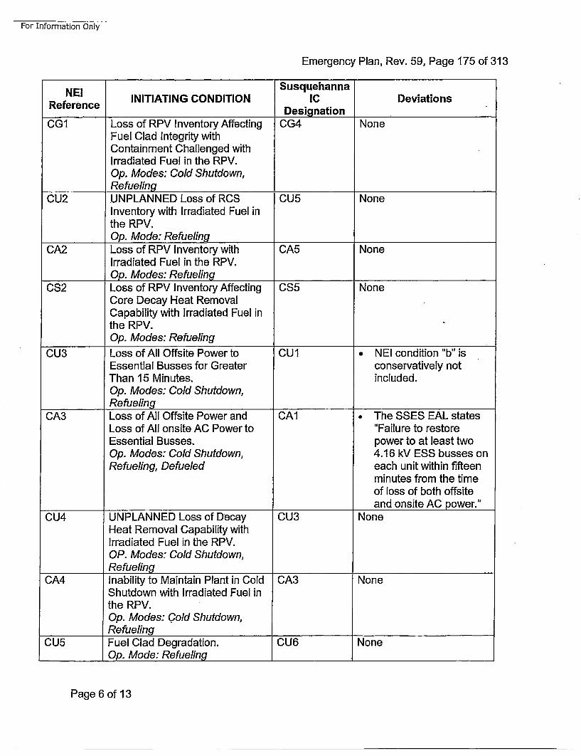
For Information Only-
Emergency Plan, Rev. 59, Page 175 of 313
NE! SusquehannaRfrne INITIATING CONDITION IC Deviations
RefernceDesignationCG1 Loss of RPV Inventory Affecting CG4 None
Fuel Clad Integrity withContainment Challenged withIrradiated Fuel in the RPV.Op. Modes: Cold Shutdown,Refueling____________
CU2 UNPLANNED Loss of RCS CU5 NoneInventory with Irradiated Fuel inthe RPV.Op. Mode: Refueling
CA2 Loss of RPV Inventory with CA5 NoneIrradiated Fuel in the RPV.
________Op. Modes: RefuelingCS2 Loss of RPV Inventory Affecting CS5 None
Core Decay Heat RemovalCapability with Irradiated Fuel inthe RPV.Op. Modes: Refueling
CU3 Loss of All Offsite Power to CU1 NEI condition "b" isEssential Busses for Greater conservatively notThan 15 Minutes. included.Op. Modes: Cold Shutdown,Re fueling
CA3 Loss of All Offsite Power and CAl1 The SSES EAL statesLoss of All onsite AC Power to "Failure to restoreEssential Busses. power to at least twoOp. Modes: Cold Shutdown, 4.16 kV ESS busses onRefueling, Defueled each unit within fifteen
minutes from the timeof loss of both offsiteand onsite AC power."
CU4 UNPLANNED Loss of Decay CU3 NoneHeat Removal Capability withIrradiated Fuel in the RPV.OP. Modes: Cold Shutdown,Refueling_______ __ _ _ _ _ _ _ _ _ _ _
CA4 Inability to Maintain Plant in Cold CA3 NoneShutdown with Irradiated Fuel inthe RPV.Op. Modes: Cold Shutdown,
_________Refueling
CU5 Fuel Clad Degradation. CU6 NoneOp. Mode: Refueling
Page 6 of 13
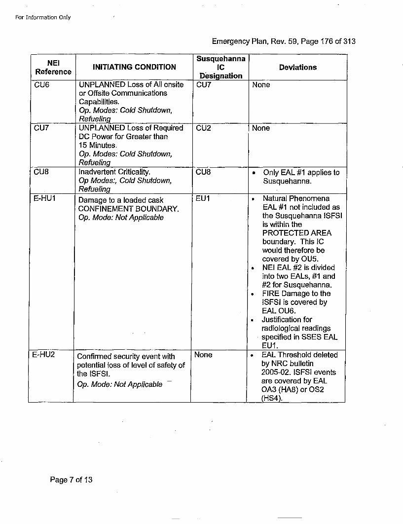
For Information Only
Emergency Plan, Rev. 59, Page 176 of 313
NEI SusquehannaRfrNcEI INITIATING CONDITION IC Deviations
RefeenceDesignationCU6 UNPLANNED Loss of All onsite CU7 None
or Offsite CommunicationsCapabilities.Op. Modes: Cold Shutdown,Re fueling_________ ____
CU7 UNPLANNED Loss of Required CU2 NoneDC Power for Greater than15 Minutes.Op. Modes: Cold Shutdown,Refueling
CU8 Inadvertent Criticality. CU8 *Only EAL #1 applies toOp Modes:, Cold Shutdown, Susquehanna.
_________ Refueling ____________
E-HU1 Damage to a loaded cask EU1 • Natural PhenomenaCONFINEMENT BOUNDARY. EAL #1 not included asOp. Mode: Not Applicable the Susquehanna ISFSI
is within thePROTECTED AREAboundary. This ICwould therefore becovered by OUS.
• NEI EAL #2 is dividedinto two EALs, #1 and#2 for Susquehanna.
* FIRE Damage to theISFSI is covered byEAL OU6.
• Justification forradiological readingsspecified in SSES EALEUI.
E-HU2 Confirmed security event with None • EAL Threshold deletedpotential loss of level of safety of by NRC bulletinthe ISFSI. 2005-02. ISFSi eventsOp. Mode: Not Applicable - are covered by EAL
OA3 (HA8) or OS2(HS4).
Page 7 of 13
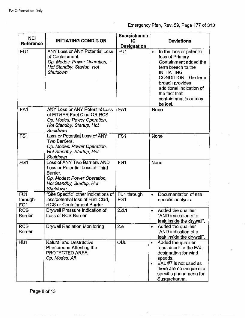
For Information Only
Emergency Plan, Rev. 59, Page 177 of 313
NE! SusquehannaReeec. INITIATING CONDITION IC Deviations
RefeenceDesignationFUI ANY Loss or ANY Potential Loss FU1 • In the loss or potential
of Containment, loss of PrimaryOp. Modes: Power Operation, Containment added theHot Standby, Startup, Hot term breach to theShutdown INITIATING
CONDITION. The termbreach providesadditional indication ofthe fact thatcontainment is or maybe lost.
FA1 ANY Loss or ANY Potential Loss FAl Noneof EITHER Fuel Clad OR RCSOp. Modes: Power Operation,Hot Standby, Startup, HotShutdown
FS1 Loss or Potential Loss of ANY FSI NoneTwo Barriers.Op. Modes: Power Operation,Hot Standby, Startup, HotShutdown
FG1 Loss of ANY Two Barriers AND FG1 NoneLoss or Potential Loss of ThirdBarrier.Op. Modes: Power Operation,Hot Standby, Startup, HotShutdown ______
FU1 "Site Specific" other indications of FU1 through • Documentation of sitethrough losslpotential loss of Fuel Clad, FGI specific analysis.FG1 RCS or Containment BarrierROS Drywell Pressure Indication of 2.d.1 • Added the qualifierBarrier Loss of RCS Barrier "AND indication of a
_________ _______________________leak inside the drywelr'.RCS Drywell Radiation Monitoring 2.e • Added the qualifierBarrier "AND indication of a
leak inside the drywelr'.HU1 Natural and Destructive OU5 * Added the qualifier
Phenomena Affecting the "sustained" to the EALPROTECTED AREA. designation for windOp. Modes: All speeds.
a EAL #7 is not used asthere are no unique sitespecific phenomena for
____ ___ ___ ____ ___ ___ ____ ___ ___ ____ ___ ___ ___ Susquehanna.
Page 8 of 13
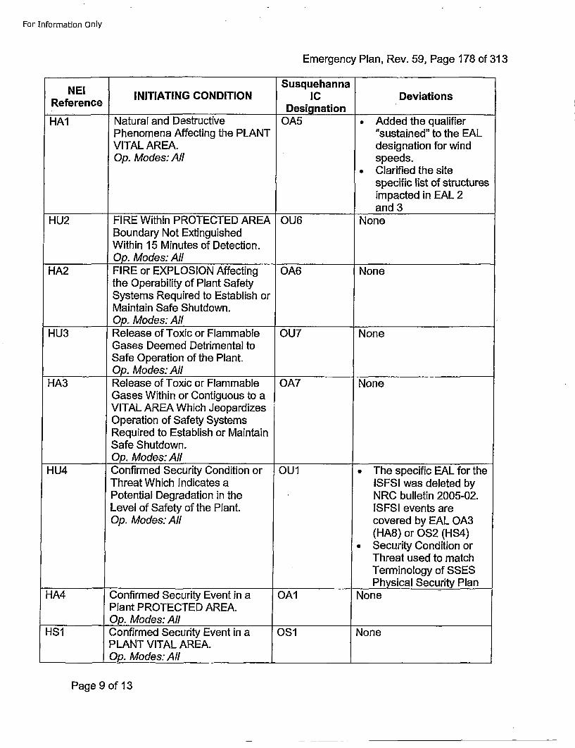
For Information Only
Emergency Plan, Rev. 59, Page 178 of 313
SusquehannaNEI INITIATING CONDITION IC DeviationsReference Designation
HA1 Natural and Destructive OA5 • Added the qualifierPhenomena Affecting the PLANT "sustained" to the EALVITAL AREA. designation for windOp. Modes: All speeds.
•Clarified the sitespecific list of structuresimpacted in EAL 2and 3
HU2 FIRE Within PROTECTED AREA OU6 NoneBoundary Not ExtinguishedWithin 15 Minutes of Detection.
________Op. Modes: All___________HA2 FIRE or EXPLOSION Affecting OA6 None
the Operability of Plant SafetySystems Required to Establish orMaintain Safe Shutdown.Op. Modes: All
HU3 Release of Toxic or Flammable OU7 NoneGases Deemed Detrimental toSafe Operation of the Plant.
________Op. Modes: AllHA3 Release of Toxic or Flammable OA7 None
Gases Within or Contiguous to aVITAL AREA Which JeopardizesOperation of Safety SystemsRequired to Establish or MaintainSafe Shutdown.Op. Modes:AI A__________
HU4 Confirmed Security Condition or OUl * The specific EAL for theThreat Which Indicates a ISESI was deleted byPotential Degradation in the NRC bulletin 2005-02.Level of Safety of the Plant. ISFSI events areOp. Modes: All covered by EAL OA3
(HA8) or OS2 (HS4)• Security Condition or
Threat used to matchTerminology of SSES
___________ Physical Security PlanHA4 Confirmed Security Event in a OA1 None
Plant PROTECTED AREA.________Op. Modes: All ________________
HS1 Confirmed Security Event in aPLANT VITAL AREA.Op. Modes: All
OS1 None
Page 9 of 13
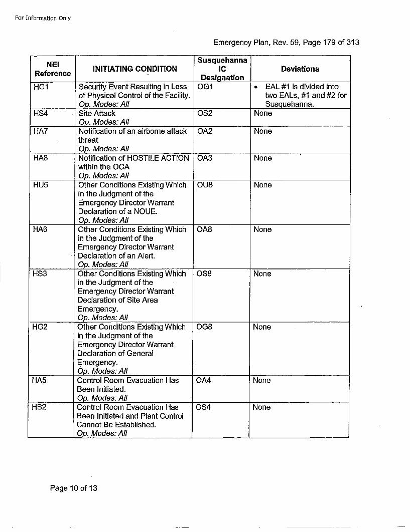
For Information Only
Emergency Plan, Rev. 59, Page 179 of 313
NEI SusquehannaRfrne INITIATING CONDITION IC Deviations
RefeenceDesignationHG1 Security Event Resulting in Loss OG1 • EAL #1is divided into
of Physical Control of the Facility, two EALs, #1 and #2 for_____Op. Modes: All Susquehanna.
HS4 Site Attack OS2 None________Op. Modes: All __________
HA7 Notification of an airborne attack OA2 NonethreatOp. Modes:AI All________
HA8 Notification of HOSTILE ACTION OA3 Nonewithin the OCAOp. Modes: All ________________
HU5 Other Conditions Existing Which OU8 Nonein the Judgment of theEmergency Director WarrantDeclaration of a NOUE.Op. Modes: All
HA6 Other Conditions Existing Which OA8 Nonein the Judgment of theEmergency Director WarrantDeclaration of an Alert.
________Op. Modes: AllHS3 Other Conditions Existing Which 0S8 None
in the Judgment of theEmergency Director WarrantDeclaration of Site AreaEmergency.Op. Modes: All
HG2 Other Conditions Existing Which OG8 Nonein the Judgment of theEmergency Director WarrantDeclaration of GeneralEmergency.Op. Modes: AIl
HA5 Control Room Evacuation Has OA4 NoneBeen Initiated.Op. Modes: All
HS2 Control Room Evacuation Has OS4 NoneBeen Initiated and Plant ControlCannot Be Established.
________Op. Modes: All ______ __________
Page 10 of 13
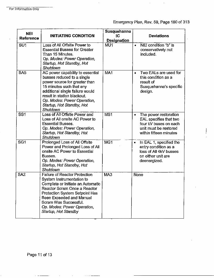
For Information Only
Emergency Plan, Rev. 59, Page 180 of 313
NEI SusquehannaRfrne INITIATING CONDITION IC Deviations
RfrneDesignation ____________
SU1 Loss of All Offsite Power to MU1 • NEI condition "b" isEssential Busses for Greater conservatively notThan 15 Minutes. included.Op. Modes: Power Operation,Startup, Hot Standby, HotShutdown ___________
SA5 AC power capability to essential MA1 Two EALs are used forbusses reduced to a single this condition as apower source for greater than result of15 minutes such that any Susquehanna's specificadditional single failure would design.result in station blackout.Op. Modes: Power Operation,Startup, Hot Standby, Hot
________Shutdown____________
SS1 Loss of All Offsite Power and MS1 The power restorationLoss of All onsite AC Power to EAL specifies that twoEssential Busses. four kV buses on eachOp. Modes: Power Operation, unit must be restoredStartup, Hot Standby, Hot within fifteen minutesShutdown____________
SG1 Prolonged Loss of All Offsite MGI *In EAL 1, specified thePower and Prolonged Loss of All entry condition as aonsite AC Power to Essential loss of All 4kV bussesBusses. on either unit areOp. Modes: Power Operation, deenergized.Startup, Hot Standby, HotShutdown ____________
SA2 Failure of Reactor Protection MA3 NoneSystem Instrumentation toComplete or Initiate an AutomaticReactor Scram Once a ReactorProtection System Setpoint HasBeen Exceeded and ManualScram Was Successful.Op. Modes: Power Operation,Startup, Hot Standby
Page 11 of 13
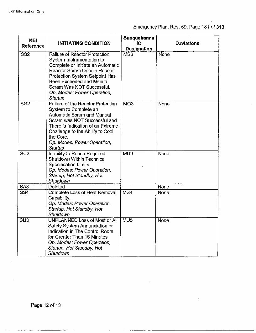
For Information Only
Emergency Plan, Rev. 59, Page 181 of 313
NEi SusquehannaRfrne INITIATING CONDITION IC Deviations
RefeenceDesignationSS2 Failure of Reactor Protection MS3 None
System Instrumentation toComplete or Initiate an AutomaticReactor Scram Once a ReactorProtection System Setpoint HasBeen Exceeded and ManualScram Was NOT Successful.Op. Modes: Power Operation,Startup
SG2 Failure of the Reactor Protection MG3 NoneSystem to Complete anAutomatic Scram and ManualScram was NOT Successful andThere is Indication of an ExtremeChallenge to the Ability to Coolthe Core.Op. Modes: Power Operation,Startup
SU2 Inability to Reach Required MU9 NoneShutdown Within TechnicalSpecification Limits.Op. Modes: Power Operation,Startup, Hot Standby, Hot
________Shutdown
SA3 Deleted NoneSS4 Complete Loss of Heat Removal MS4 None
Capability.Op. Modes: Power Operation,Startup, Hot Standby, Hot
________Shutdown
SU3 UNPLANNED Loss of Most or All MU5 NoneSafety System Annunciation orIndication in The Control Roomfor Greater Than 15 MinutesOp. Modes: Power Operation,Startup, Hot Standby, HotShutdown
Page 12 of 13
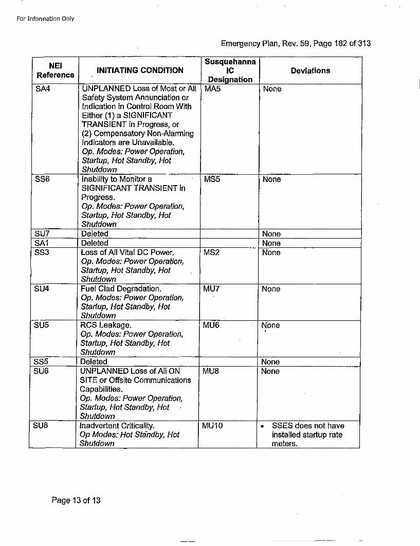
For Information Only
Emergency Plan, Rev. 59, Page 182 of 313
NEIReference INITIATING CONDITION
SusquehannaICDesignation
Deviations
SA4 UNPLANNED Loss of Most or All MA5 NoneSafety System Annunciation orIndication in Control Room WithEither (1) a SIGNIFICANTTRANSIENT in Progress, or(2) Compensatory Non-AlarmingIndicators are Unavailable.Op. Modes: Power Operation,Startup, Hot Standby, HotShutdown
SS6 Inability to Monitor a MS5 NoneSIGNIFICANT TRANSIENT inProgress.Op. Modes: Power Operation,Startup, Hot Standby, HotShutdown ___________
SU7 Deleted _______None
SA1 Deleted NoneSS3 Loss of All Vital DC Power. MS2 None
Op. Modes: Power Operation,Startup, Hot Standby, HotShutdown___________
SU4 Fuel Clad Degradation. MU7 NoneOp. Modes: Power Operation,Startup, Hot Standby, HotShutdown
SU5 RCS Leakage. MU6 NoneOp. Modes: Power Operation,Startup, Hot Standby, HotShutdown
SS5 Deleted NoneSU6 UNPLANNED Loss of All ON MU8 None
SITE or Offsite CommunicationsCapabilities.Op. Modes: Power Operation,Startup, Hot Standby, HotShutdown
SU8 Inadvertent Criticaliy. MU1 0 *SSES does not haveOp Modes: Hot Staindby, Hot installed startup rate
______Shutdown meters.
Page. 13 of 13
For Information Only
Emermcencv Plan. Rev. 59, Pa~Qe 183 of 313
APPENDIX GSSES EVACUATION TIME ESTIMATES
ORIGINAL DOCUMENT ISSUED 11/2012
Page 1lof 23

For Information Only
Emergency Plan, Rev. 59, Page 184 of 313
NOTE: The information contained in Appendix G is a copy of the executive summary of the November2012 Evacuation Time Estimate. The entire Evacuation Time Estimate can be found in theSusquehanna Information Management System which also stores the annual reviews.
Page 2 of 23
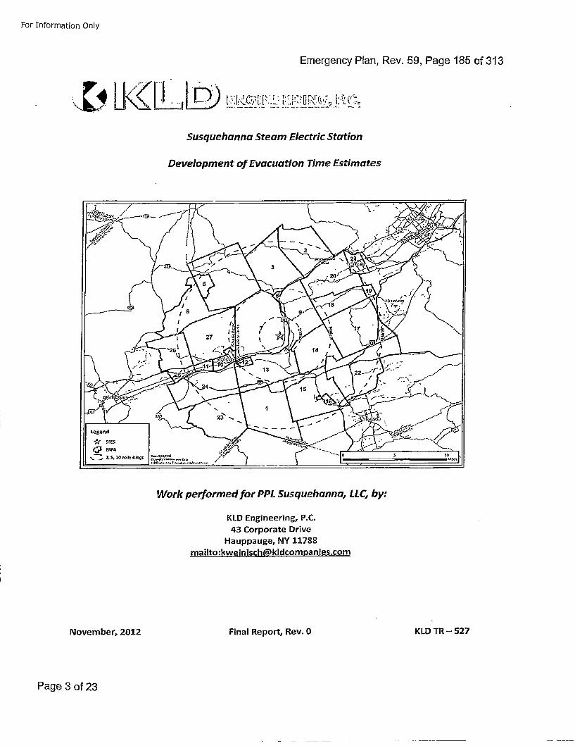
For Information Only
Emergency Plan, Rev. 59, Page 185 of 313
Susquehanna Steam Electric Station
Development of Evacuation Time Estimates
Work performed for PPL Susquehanna, LLC, by:
KID Engineering, P.C.43 Corporate Drive
Hauppauge, NY 11788mailto:kweinisch~kldcompanies.com
November, 2012 Final Report, Rev. 0 KLD TR -527
Page 3 of 23
For Information Only
Emergency Plan, Rev. 59, Page 186 of 313
EXECUTIVE SUMMARY
This report describes the analyses undertaken and the results obtained by a study to developEvacuation Time Estimates (ETE) for the Susquehanna Steam Electric Station (SSES) located inLuzerne County, Pennsylvania. ETE are part of the required planning basis and provide PPLSusquehanna, LIC (PPL) and state and local governments with site-specific information neededfor Protective Action decision-making.
In the performance of this effort, guidance is provided by documents published by FederalGovernmental agencies. Most important of these are:
* Criteria for Development of Evacuation Time Estimate Studies, NUREG/CR-7002,November 2011.
* Criteria for Preparation and Evaluation of Radiological Emergency Response Plans andPreparedness in Support of Nuclear Power Plants, NUREG-0654/FEMA-REP-1, Rev. 1,November 1980.
*Development of Evacuation Time Estimates for Nuclear Power Plants, NUREG/CR-6863,January 2005.
*10CFR5O, Appendix E -- "Emergency Planning and Preparedness for Production andUtilization Facilities"
Overview of Proiect ActivitiesThis project began in March, 2012 and extended over a period of 6 months. The major
activities performed are briefly described in chronological sequence:
* Attended "kick-off" meetings with PPL personnel.
* Accessed U.S. Census Bureau 'data files for the year 2010. Studied GeographicalInformation Systems (GIS) maps of the area in the vicinity of the SSES, then conducted adetailed field survey of the highway network.
* Synthesized this information to create an analysis network representing the highwaysystem topology and capacities within the Emergency Planning Zone (EPZ), plus aShadow Region covering the region between the EPZ boundary and approximately 15miles radially from the plant.
*Designed and sponsored a telephone survey of residents within the EPZ to gatherfocused data needed for this ETE study that were not contained within the censusdatabase. The survey used was carried out in 2008; it is still valid since there has notbeen a significant change in EPZ demographics. The survey instrument had beenreviewed and modified by the licensee and offsite response organization (ORO)personnel prior to conducting the survey.
* Data collection forms (provided to PPL at the kickoff meeting) were returned with data
Susquehanna Steam Electric Station E- KLD Engineering, P.C.Evacuation lime Estimate Rev. 0
Page 4 of 23
For Inf'ormation Only
Emergency Plan, Rev. 59, Page 187 of 313
pertaining to employment, transients, and special facilities in each county.
eThe traffic demand and trip-generation rates of evacuating vehicles were estimatedfrom the gathered data. The trip generation rates reflected the estimated mobilizationtime (i.e., the time required by evacuees to prepare for the evacuation trip) computedusing the results of the telephone survey of EPZ residents.
aFollowing federal guidelines, the EPZ is subdivided into 27 ERPA. These ERPA are thengrouped within circular areas or "keyhole" configurations (circles plus radial sectors)that define a total of 30 Evacuation Regions.
* The time-varying external circumstances are represented as Evacuation Scenarios, eachdescribed in terms of the following factors; (1) Season (Summer, Winter); (2) Day ofWeek (Midweek, Weekend); (3) Time of Day (Midday, Evening); and (4) Weather (Good,Rain, Snow). One special event scenario - refueling at the plant - was considered. Oneroadway impact scenario was considered wherein a single lane was closed on Interstate80 westbound for the duration of the evacuation.
* Staged evacuation was considered for those regions wherein the 2 mile radius andsectors downwind to 5 miles were evacuated.
* As per NUREG/CR-7002, the planning basis for the calculation of ETE is:
* A rapidly escalating accident at the SSES that quickly assumes the status ofGeneral Emergency such that the Advisory to Evacuate is virtually coincidentwith the siren alert, and no early protective actions have been implemented.
* While an unlikely accident scenario, this planning basis will yield ETE, measuredas the elapsed time from the Advisory to Evacuate until the stated percentage ofthe population exits the impacted Region, that represent "upper bound"estimates. This conservative Planning Basis is applicable for all initiating events.
* If the emergency occurs while schools are in session, the ETE study assumes that thechildren will be evacuated by bus directly to reception centers or host schools locatedoutside the EPZ. Parents, relatives, and neighbors are advised to not pick up theirchildren at school prior to the arrival of the buses dispatched for that purpose. The ETEfor schoolchildren are calculated separately.
*Evacuees who do not have access to a private vehicle will either ride-share withrelatives, friends or neighbors, or be evacuated by buses provided as specified in thecounty evacuation plans. Those in special facilities will likewise be evacuated withpublic transit, as needed: bus, van, or ambulance, as required. Separate ETE arecalculated for the transit-dependent evacuees, for homebound special needspopulation, and for those evacuated from special facilities.
Computation of ETE
A total of 420 ETE were computed for the evacuation of the general public. Each ETE quantifies
the aggregate evacuation time estimated for the population within one of the 30 Evacuation
Susquehanna Steam Electric Station ES-2 KID Engineering, P.C.
Evacuation Time Estimate Rev. 0
Page 5 of 23
For Information Only
Emergency Plan, Rev. 59, Page 188 of 313
Regions to evacuate from that Region, under the circumstances defined for one of the 14Evacuation Scenarios (30 x 14 = 420). Separate ETE are calculated for transit-dependentevacuees, including school children for applicable scenarios.
Except for Region R03, which is the evacuation of the entire EPZ, only a portion of the peoplewithin the EPZ would be advised to evacuate. That is, the Advisory to Evacuate applies only tothose people occupying the specified impacted region. It is assumed that 100 percent of thepeople within the impacted region will evacuate in response to this Advisory. The peopleoccupying the remainder of the EPZ outside the impacted region may be advised to takeshelter.
The computation of ETE assumes that 20% of the population within the EPZ but outside theimpacted region, will elect to "voluntarily" evacuate. In addition, 20% of the population in theShadow Region will also elect to evacuate. These voluntary evacuees could impede those whoare evacuating from within the impacted region. The impedance that could be caused byvoluntary evacuees is considered in the computation of ETE for the impacted region.
Staged evacuation is considered wherein those people within the 2-mile region evacuateimmediately, while those beyond 2 miles, but within the EPZ, shelter-in-place. Once 90% of the2-mile region is evacuated, those people beyond 2 miles begin to evacuate. As per federalguidance, 20% of people beyond 2 miles will evacuate (non-compliance) even though they areadvised to shelter-in-place.
The computational procedure is outlined as follows:
* A link-node representation of the highway network is coded. Each link represents aunidirectional length of highway; each node usually represents an intersection or mergepoint. The capacity of each link is estimated based on the field survey observations andon established traffic engineering procedures.
• The evacuation trips are generated at locations called "zonal centroids" located withinthe EPZ and Shadow Region. The trip generation rates vary over time reflecting themobilization process, and from one location (centroid) to another depending onpopulation density and on whether a centroid is within, or outside, the impacted area.
* The evacuation model computes the routing patterns for evacuating vehicles that arecompliant with federal guidelines (outbound relative to the location of the plant), thensimulate the traffic flow movements over space and time. This simulation processestimates the rate that traffic flow exits the impacted region.
The ETE statistics provide the elapsed times for 90 percent and 100 percent, respectively, of thepopulation within the impacted region, to evacuate from within the impacted region. Thesestatistics are presented in tabular and graphical formats. The 90th percentile ETE have beenidentified as the values that should be considered when making protective action decisionsbecause the 1 0 0 th percentile ETE are prolonged by those relatively few people who take longerto mobilize. This is referred to as the "evacuation tail" in Section 4.0 of NUREG/CR-7002.
The use of a public outreach (information) program to emphasize the need for evacuees to
Susquehanna Steam Electric Station ES-3 KLD Engineering, P.C.Evacuation Time Estimate Rev. 0
Page 6 of 23
For Information Only
Emergency Plan, Rev. 59, Page 189 of 313
minimize the time needed to prepare to evacuate (secure the home, assemble needed clothes,medicines, etc.) should also be considered.
Traffic Management
This study references the comprehensive traffic management plans provided in the Luzerne andColumbia County Radiological Emergency Response Plans. Due to the detailed plans already inplace and the limited traffic congestion within the EPZ, no additional traffic or access controlmeasures have been identified as a result of this study.
Selected Results
A compilation of selected information is presented on the following pages in the form of figures
and tables extracted from the body of the report; these are described below.
* Figure 6-1 displays a map of the SSES EPZ showing the layout of the 27 ERPA thatcomprise, in aggregate, the EPZ.
* Table 3-1 presents the estimates of permanent resident population in each ERPA basedon the 2010 Census data.
* Table 6-1 defines each of the 30 Evacuation Regions in terms of their respective groupsof ERPA.
* Table 6-2 lists the Evacuation Scenarios.* Tables 7-1 and 7-2 are compilations of ETE. These data are the times needed to clear
the indicated regions of 90 and 100 percent of the population occupying these regions,respectively. These computed ETrE include consideration of mobilization time and ofestimated voluntary evacuations from other regions within the EPZ and from the
Shadow Region.* Tables 7-3 and 7-4 presents ETE for the 2-mile region for un-staged and staged
evacuations for the 9 0 th and 1 0 0 th percentiles, respectively.* Table 8-7 presents ETE for the schoolchildren in good weather.* Table 8-11 presents ETE for the transit-dependent population in good weather.* Figure H-B presents an example of an Evacuation Region (Region R08) to be evacuated
under the circumstances defined in Table 6-1. Maps of all regions are provided inAppendix H.
Conclusions
*General population ETE were computed for 420 unique cases - a combination of 30unique Evacuation Regions and 14 unique Evacuation Scenarios. Table 7-1 and Table 7-2document these ETE for the 9 0 th and 1 0 0 th percentiles. These ETE range from 1:40(hr:min) to 3:35 at the 90h percentile.
*Inspection of Table 7-1 and Table 7-2 indicates that the ETE for the 1 0 0 th percentile aresignificantly longer than those for the 9 0 th percentile. This is the result of the relativelylong mobilization time of a small proportion of the resident population and congestionwithin the EPZ. When the system becomes congested, traffic exits the EPZ at ratessomewhat below capacity until some evacuation routes have cleared. As more routes
Susquehanna Steam Electric Station ES-4 KLD Engineering, P.C.Evacuation Time Estimate Rev. 0
Page 7 of 23
For Information Only
Emergency Plan, Rev. 59, Page 190 of 313
clear, the aggregate rate of egress slows since many vehicles have already left the EPZ.*Towards the end of the process, relatively few evacuees (those with the longest
mobilization times) travel freely out of the EPZ. See Figures 7-8 through 7-21.*Inspection of Table 7-3 and Table 7-4 indicates that a staged evacuation provides no
benefits to evacuees from within the 2 mile region and unnecessarily delays theevacuation of those beyond 2 miles (compare Regions R25 through R30 and Regions R04through R08 and R02, respectively, in Tables 7-1 and 7-2). See Section 7.6 for additional
discussion.SComparison of Scenarios 6 and 13 in Table 7-1 indicates that the Special Event -
refueling outage at the plant -- does not have a significant impact on the ETE for the 90t'percentile. See Section 7.5 for additional discussion.
o Comparison of Scenarios 1 and 14 in Table 7-1 indicates that the roadway closure - onelane westbound on 1-80 from the interchange with SC 339 to the EPZ boundary - doesnot change the ETE, indicating that there is excess capacity on the highway. See Section
7._5.* Nanticoke City and Briar Creek Borough and Township are the most congested areas
during an evacuation. The last roadway in the EPZ to exhibit traffic congestion is SC 93.All links within the EPZ are at LOS A (free-flowing traffic conditions) at 3 hours and 20minutes after the Advisory to Evacuate. See Section 7.3 and Figures 7-3 through 7-7.
* Separate ETE were computed for schools, medical facilities, transit-dependent persons,homebound special needs persons and correctional facilities. The average single-waveETE for these sources are within a similar range as the general population ETE at the 9 0 th
percentile. See Section 8.*Table 8-5 indicates that there are enough buses and wheelchair vans available to
evacuate the transit-dependent population within the EPZ in a single wave; however,aid agreements with other counties will need to be activated in order to provide enoughambulances to evacuate the bedridden population in a single wave. See Sections 8.4and 8.5.
*The general population ETE at the 9 0 th percentile is insensitive to reductions in the basetrip generation time of 4 hours since the mobilization time of the bulk of evacuees isunchanged by the truncation. See Table M-I.
* The general population ETE is relatively insensitive to the voluntary evacuation ofvehicles in the Shadow Region (tripling the shadow evacuation percentage onlyincreases 9 0 th percentile ETE by 5 minutes). See Table M-2.
* Population changes between +30% or -46% are needed to result in ETE changes whichmeet the criteria for updating ETE between decennial Censuses. See Section M.3.
Susquehanna Steam Electric Station ES-5 KLD Engineering, P.C.Evacuation Time Estimate Rev. 0
Page 8 of 23
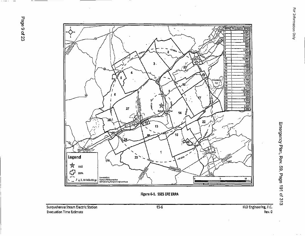
"1/
Figure 6-1. SSES EPZ ERPA
Susquehanna Steam Electric Station ES-6
Evacuation Time Estimate
ERPA"I Pop~ulation 2010
0 2,107
1[,1"[ 3 2,04
"*1
¢0
CD
01
--uir
KLD Engineering, P.C.Rev. 0
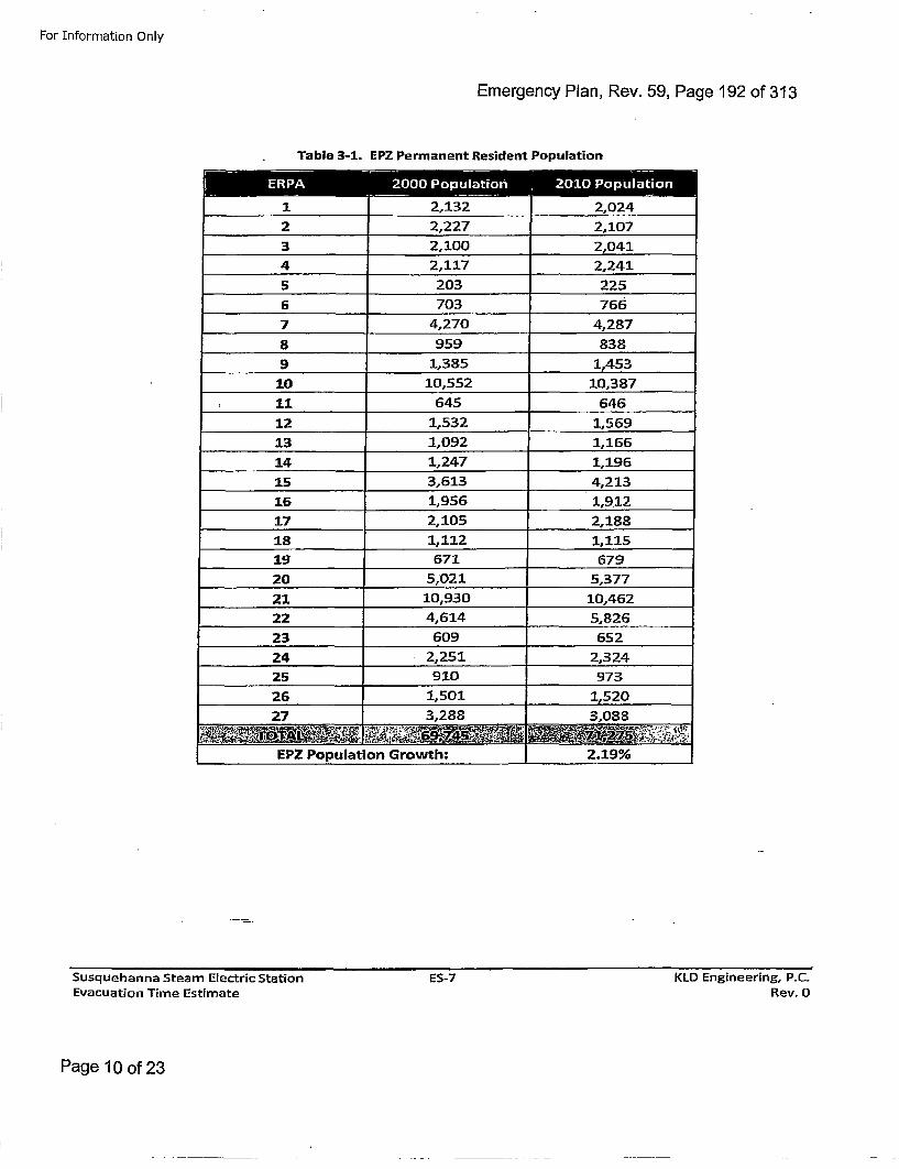
For Information Only
Emergency Plan, Rev. 59, Page 192 of 313
Table 3-1. EPZ Permanent Resident Population
3 2,100 2,041
4 2,117 2,241
1 ,2470 4,287_____
9 _________1,98561 5
10 ~ ~ 210,551,8
18 1,1121,6
20 5,0921 1,166_____
21 10,930 1,196_______
25 9,10 9723
26 1,9501 1,5120
27 328852,8__ 8O A1,1 2~ 1,15 . -
EP oulto Groth 219%
Susquehanna Steam Electric StationEvacuation Time Estimate
ES-7 KLD Engineering, P.C.Rev. 0
Page 10 of 23
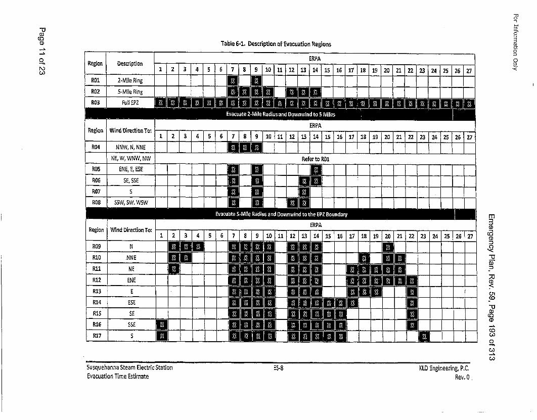
0-4,
Table 6-1. Description of Evacuation Regions
"110
o1
o
-C
0<Region Description -....-
R0l 2-Mile Ring II gJ
R02 5-Mile RingiIll}lIIlli Ii
__ __ 2 _ 4 5 6 7_ 91 11j2 3p4 LJj167pB[19 20 21 22 23 24 25 26j2
NE, W, WNW, NW
ROS ENEEESE
RU6 SE, SSE
R07 S
Refer to RO
UXITh-|
0U
II I I I I .1 I
ROB ISSW, SW, WSW I I I I I I I
Region ERPAWind Directon To: r ii.,,,,1
R09 N
R10 .NNE
2 3 4 SIBII IBi i•1
23 j24 25 I261 27
Rlu NE
R12 ENER13 E
R14 ESE
RiS SE
R16 SSE
R17 S I!
I m
CD
0,Co
"0-4,
SusquehannaStearn Electric StationEvacuation Time Estimate
ES-8 KID Engineering, PC,Rev. 0
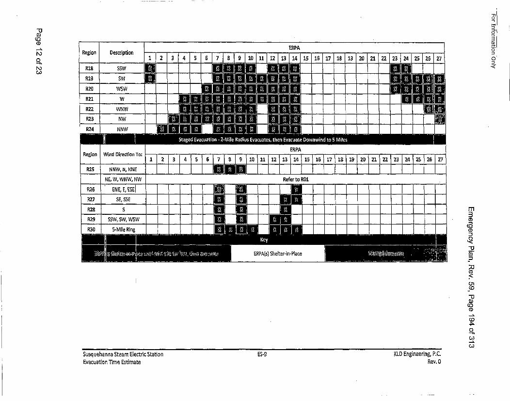
"D
CD
0
0.h
-n0
01Region ERPADescription . , n i I
iJ 23 { 4 5 5 7 8 9 iDhil 12 13 14115115117118119120121.... I
RegionERPA
Wind Direction To: 1 2 3 T 6 8 1 f11I51181IO 121421627
R5 NNW, N, NNEIL [LI iI E I] IL 1NE, W, WNW, NW Refer to R0l26 ENE, E,ESEl __ , I i
R7 SE, SSE
R8 SSW W S m2Co
-D
-U
CD!"13
0,
CO
0
Susquehanna Steam Electric StationEvacuation Time Estimate
ES-9 KLD Engineering, P.C.Rev.O0
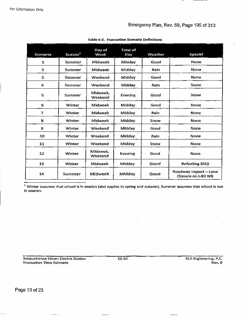
For Information Only
Emergency Plan, Rev. 59, Page 195 of 313
Table 6-2. EvacuatIon Scenario Definitions
3. . -.
1. Summer Midweek Midday Good None
2 Summer Midweek Midday Rain Nn
3 Summer Weekend Midday Good Nn
4 Summer Weekend Midday Rain Nn
SSummer MiWeekn Evening Good Nn
6 Winter Midweek Midday Good None
7 Winter Midweek Midday Rain None
8 Winter Midweek Midday Snow None
9 Winter Weekend Midday Good None
10 Winter Weekend Midday Rain None
11 Winter Weekend Midday Snow None
1:2 Winter Midweek, EvngGodNeWeekend EvnnGodNe
13 Winter Midweek Midday Good Refueling SSES
Roadway Impact- Lane14 Summer Midweek Midday Good Closure on 1-80 WB
SWinter assumes that school is in session (also applies to spring and autumn). Summer assumes that school is not
in session.
Susquehanna Steam Electric StationEvacuation Time Estimate
ES-lO KLD Engineering, P.C.Rev. 0
Page 13 of 23
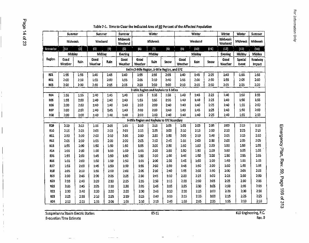
Co(p
0o
Table 7-1. lime to Clear the Indicated Area of 90 Percent of the Affected Population
M____________ ___ nirwek 2-ieRidweeMlkRgo ndEZ ____ ____RMidwe :5ek0 :5 1:0 155 15 3 T 14 1:45ed 2:25ek1ek40 1id50. 1:55ee
________ ________ ______ ________ Entre_2-Mile Region, and-ehle tegon 5 n MiesPZ__ ___ ____ _______R04 1:55 1:55 1:4.0 1.:45 '1':40 1:55 1:55 2:35 1:40 1:45' 2:25' 1:40 .1:50. 1:55"R02 :5 2:00 1:40 1: 40 1:40 1:55 1:55 2: 35 1:40 1: 40 2: 25 1:40 1:55 205 1:55R03 2:00 2:00 1:40 1:40 1:40 2:00 2:0 2:40:0 1:40 1:40 2:250 1:40 1:55 2:00R07 2:00 .2:55 1:40 1:45. 1:40 2:00 1:00 2:40 1:40 1:45 2:25 1:40 .1:50 2:00RO5 2:00 2:00 1:40 1:40 1:40 2:00 2:00 2:40 1:40 1:40 2:25 1:40 1:55 2:00R07 2:10 ,2:015 1:55 2:0.5. 1:55 2:10 2:15 2.:55 1:550 2:05 2:35 2:00 2150 2:10mR08 2:15 2:25 2:405 2154 14 2:05 2:15 2:25 3:00 2:1 0 2:15 2:50 210 2:25 2:15
R10 2:10 2:20 2:00 2:10 2:05 2:10 2:20 2:50 2:00 2:10 2:40 2:05 2:15 2:10 Co
R12 2:05 2:10 1:55 2:00 2:00 2:05 2:10 2:45 1:55 2:00 2:30 2:00 2:05 2:05 :R13 1:55 2:00 1:50 1:50 1:50 1:55 2:00 2:30 1,:50 1:50 2:20 1:50 1:55 1:.55R14 1:55 2:00 1:50 1:50 1:50 1:55 2:00 2:30 1:50 1:50 2:20 1:50 1:55 1:55 •RI5 1:55 2:00 1:45 1:50 . 1:50 1:5.5 2:00 2:30 1:45 1:50 '2:20 1:50 1:55. 1:55 "R16 1:55 2:00 1:50 1:50 1:50 1:55 2:00 2:30 1:45 1:50 2:20 1:50 1:55 1:55 ;R17 1:55 2:00 1:45 1:50. 1:50 1:55 2:00 .2:30 1:45 1:50 2:20 1:50' 1:55 1:55.•R18 2:05 2:10 1:55 2:00 2:00 2:05 2::10 2:40 1:55 2:00 2:30 2:00 2:05 2:05R19 2:30 2:.45 2:20 2:25 2:25 2:30 2:45 3:10 2:20 2:25 3:00 2:25 2:30 2:30
"1)1120 2:35 2:40 2:20 2:30 2:25 2:35 2:50 3:15 2:20 2:30 3:05 2:25 2:30 2:35P121 2:35 2:45 2:25 2:30 2:30 2:35 2:45 3:15 2:25 2:30 3:05 2:30 2:35 2:35' 0R22 2:30 2:40 2:20 2:30 2:20 2:30 2:40 3:10 2:20 2:25 3:00 2:20 2:30 2:30 co-.C)R23 2:25 2:35 2:10 2:25' 2:15" 2"25 ,2:40 3:10 2:15 2:20, 3:00 '2:15 2:25 2:25o_R24 2:10 2:15 1:55 2:05 1:55 2:10 2:15 2:45 1:55 2:05 2:35 1:55 2:10 2:10 •--.)
"11
-5
DJ
0
"-
.Susquehanna Steam Electric StationEvacuation Time Estimate
ES-il KID Engineering, PC.Rev, 0
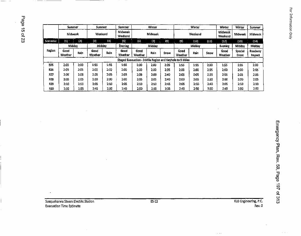
0D
(0CD01
"110
DJ0,m
0
Summer Summer Summer Winter WitrWinter Winter SummerMidweek Midweek
Midweek Weekend ekndMidweek Weekend Wend Midweek Midweek-ekndW-knMidday Midday Evening Midday , MidEvening Midday Midday.
WeathrRai Weather, Weather Weather , Weather Weather Event Impact
_______ _______ _____ _______ ______Staged Evacuation - 2-Mile Region and Keyhole to 5SMiles_____________ ____
l•25 2,:00 2:00 1:55 1:55 1:55 2:00 2:00 2:35 1:55 1:55 2:30 1:55 1:55 2:00R26 2:05 2:05 2:00 2:00 2:00 2:00 2:00 2:35 2:00 2:00 2:35 2:00 2'O0 2:05'R27 2:05' 2:05 2:05 2:05 2:05 2:05 2:05 . 2:40 2:05 2:05 2:35 2"05 2:05 2:05.RZ8 2:05 2'.05 2:00 2:00 2:00 2:05 2:05 2:40 2:00 2:00 2:35 2:00 2:00 2:05R2.9 2:10 2:10 2:05 2':10 2:05 2":10 2:10 .2:45 2:05 2:10. 2:40 2:05 2:10 2:10
R30 2:50 2:55 2:45 2:50 2:45 2:50 2:55 3:35 2:45 2:50 3:30 2:45 2:50 2:50
CD
CDC.<
"13
0)CD
0"-h
Susquehanna Steam Electric StationEvacuation lime Estimate
ES -12 KLD Engineering, P,.CRev. 0
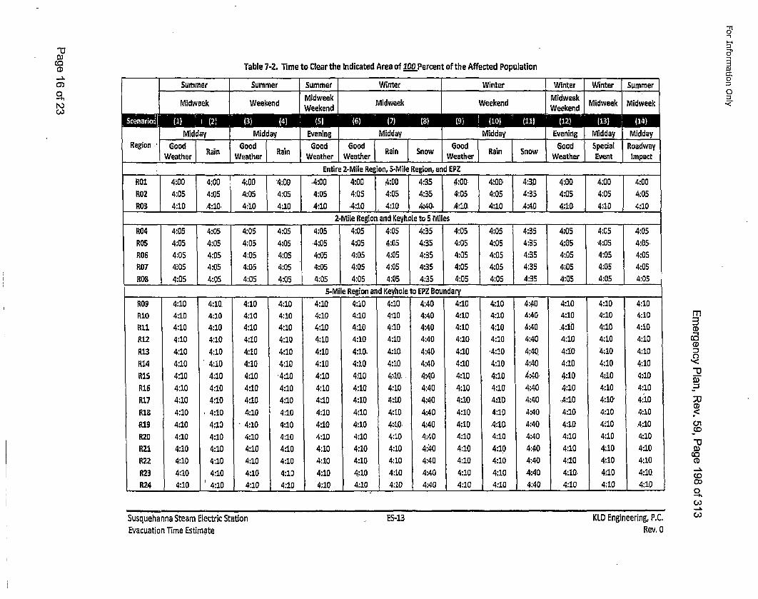
-o
CD
0..%oh
N,o'3
Table 7-2. lime to Clear the Indicated Area of 100 Percent of the Affected Population
M________ nirwek M-ieieind5Mlwegoaneek________ ___
__egion .___ood_ __ood _ 2-Mo l Regonad Kyoet 5 Miles ____ _____ ood__ __pedl Roadway
R04 4:05 4:05 4:05 '4:05 .4:05 4:05 .4:05 4:35 4:05, 4:,05 4:350 4:05 4:05 4:05ROS 4:05 4:05 4:05 4:05 4:05 4:05 4:05 4:35 4:05 4:05 4:35 4:05 4:05 4:05R05 4:05 .4:105 4::05 4:05 4:05 .4:05 4:05 4:35, .4:105 4:05 4:435 4•:05 4:05 4:105
R04 4:05 4:05 4:05 4:05 4:05 4:05 4:05 4:35 4:05 4:05 4:35 4:05 4:05 4:05ROB 4:05 4:05 j4:05 4:05 .4:05 4:05 4:05 4:35 4:05 [4:05 4:35 4:05 4:05 4:05.R06 4:105 4:10. 4:105 4:105 4:105 4:105 4:105 4:40 4:105 4:10 4:40 4:105 4:105 4:105R0O 4:10 4:10 4:10 4:105 4:105 4:105 4:10 4:40 4:10 4:105 4:40 4:10 4:10 4:105ROB 4:10 4:105 4:10 4:105 4:.05 4:105 4:105 4:40 4:10 4:105 4:40 .4:105 4:10 4:105R12 4:10 4:10. 4:10 '4:10 4:2.0 4:1.0 4:10 4:40 4:10 4:10 4:,40 4:10 4:10 4:10)R1O 4:10 4:10 4:10 4:10 4:10 4:10. 4:10. 4:40 4:10 4:10 4:40 4:10 4:10 4:10R14 4:10 4:10 4:10 4:10 4:1.0 4:10 4:10 4:40 4:10 4:10 4:40 .4:10 4:10 4:10Ri12 4:10 4:10 4:10 4:10 4:10 4:10 4:10. 4:40 4:10 4:10 4:40 4:10 4:10 4:10R13 4:10 4:10 4:10 4:10 4:10 4:10. 4:10. 4:40 4:10 '4:10 4:40. 4:10 4:10 4:10R14 4:10 4:10 4:10 4:10 4:10 4:10 4:10 4:40 4:10 4:10 4:40 .4:10 4:10 4:10R15 4:10 4:10 4:10 '4:10 4:10 4:"10 4:,10. 4:40 4:10 4:10 4:.40. 4:2.0 4•:10 4:10R19 4:10 4:10 4:10 4:10 4:10 4:10 4:10. 4:40 4:10 .4:10. 4:40 4:10 4:10 4:10R207 4:10 4:10 4:10 4:10 4:10 4:10 4:10 4:40 4:10 4:10 4:40 .4:10 4:10' 4:'10.RZ1 4:10 ,4:10 4:10 4:10 4:10 4:10 4:10 4:40 4:10 4:10 4:40 4:10 4:10 4:10R19 4:10 4:10 "4:10 4:10 4:10 4:10 4:10O 4:40 4:10 .4:10. 4:40 4:10 4:10 .4:10R23 4:10 4:10 4:10 4:10 4:10 4:10 4:1.0 4:40 4:10 4:10 4:40 4:10. 4:10 4:10.R24 4:10 4:10 4:10 4:10 4:10 4:10 4:1.0 4:40 4:10 4:1.0 4:40 4:10 4:10 4:10
"-I
0
o-I
0<
m
CD
CD
01
;0
CD
C.D
"0
,--h
('3Susquehanna Steam Electric StationEvacuation Time Estimate
ES-13 KID Engineering, P.C.Rev, 0
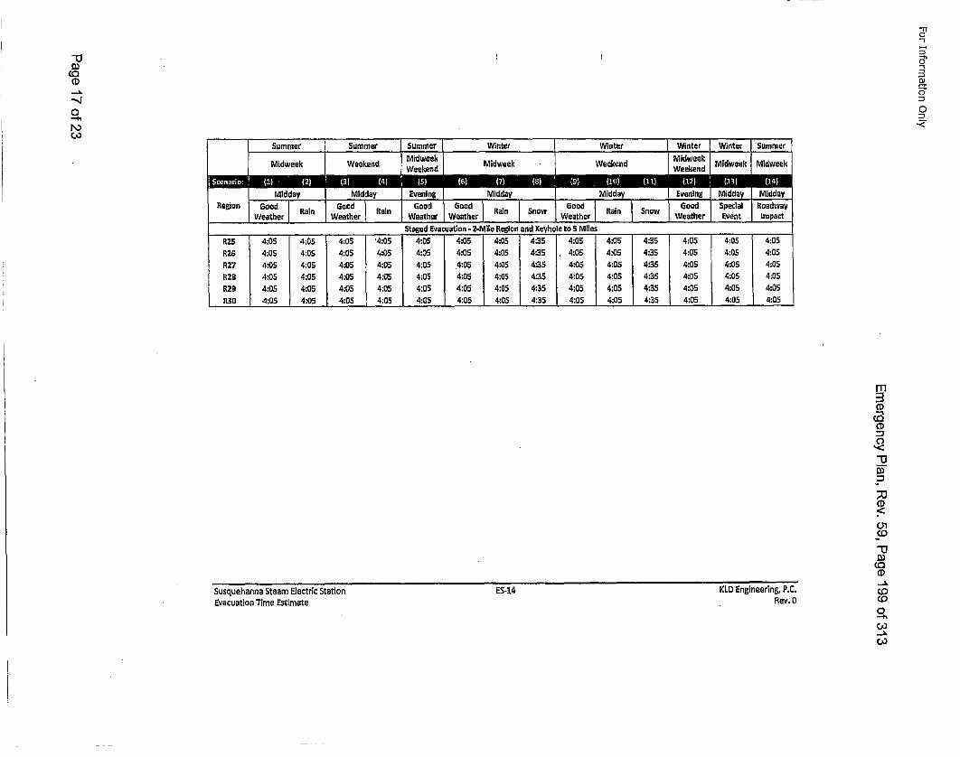
-0
--.
S'.8'
o1
0
,<J
R25 4:05 4:05 4:05 '4:05 4:05 4:05 4:05 4:35 4:05 4:05 4"35 4:05R26 4:05 4:05 4:05 4:05 4:05 4:05 4:05 4:BS 4:0.5 4:05 4:35 4:05R27 4:05 4:05 4:05 4:05 4:05 4:05 4:05 4:35 4:0.5 4:05 '4,35 4:05R128 4:05 4:05 4:05 4:05 4:05 4:05 4:05 4:35 4:05 4:05 4:35 4:05R29 4:05 4:05 4:05 4:05 4:05 4:05 4:05 4:35 4:05 4:05 4:35 4:051130 4:05 4:05 4:05 4:05 4:05 4:05 4:05 4:35 4:05 4:05 4:35 4:05
4:05 404:05 404:05 404:05 40
4:054:05
4:05
4:054:05
4:05
4:05 4:054:05 4:05
-IT
CD
CD
CO
CD
0•
C,,
Susquehanna Steam Electric StationEvacuation "1ime Estimate
E5-14 KLD Engineering, P.C.Rev. 0
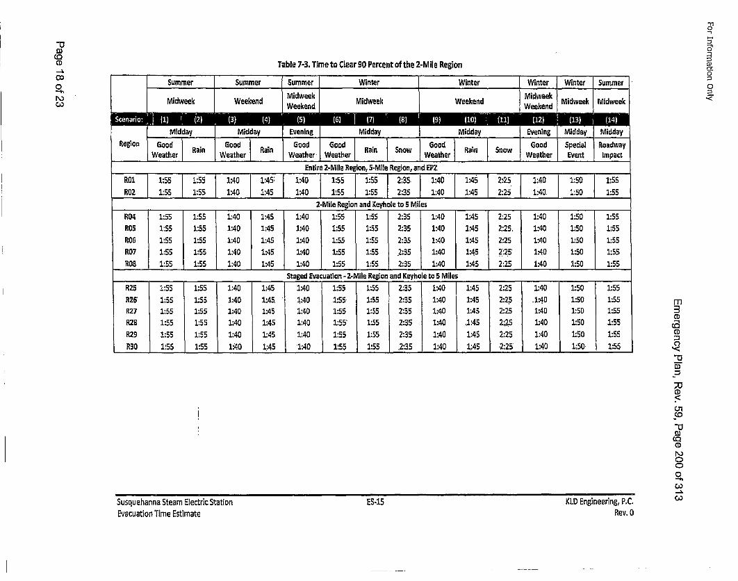
CD
O0oh
Table 7-3. Time to Clear 90 Percent of the 2-Mile RegionSummer___ __ __ um___er __ Summerwinte Winter Winter Winter Summer
Region Good Good Good Good RaiodSnopecialerRoadwayoWete an Weather Ran Weather. Weather ,Weather Event Impact
'Entire 2-Mile Region, 5-Mile Region, and EPZ
RO2. 1:55 1:55 1:40 [1:45: 1:40 1:55 [1:55 2:35. 1:40 1:45 2:25 1:40. 1:50 1:55ROZ 1:55 1:55 1:40 [1:45 1:40 1:55 [1:55 2:35 1:40 1:45 2:25 1:40. 1:50 1:55
RO4 1:55 1:55 1:40 1:45 1:40 1:55 1:55 2:35 1:40 1:45 2:25. 1:40 1:50 1:55R05f 1:55 1:55 1:40 1:45 1:40 1:55 1:55 2:35 1:40 1:45 2:25. 1:40 1:50 1:55RO7 1:55 1:55 1:40 1:45 1:40 1:55 1:55 2:35 1:40 1:45 21:25' 1:40 1:.50 1:55RO7 1:55 1:55 1:40 1:45 1:40 1:53 1:55 .2:35 .1:40 1:45 2:25 1:40 1:50 1:55
_______ ______ ______ ______ ______ StagedEvacuation - 2-Mile Region andKeyhole__ to .5 Miles_____________RZS 1:55 1:55 1:.40 1:45 1:40 1:55 1:55 2:35 1:40 1:45 2:25 1:40 1:50 1:55R26 1:55 1:55 1:40 1:45. .1:40 1:55. 1:55 2:35 1:40 1:45 2:25 .1:4.0 1:50 1:55R27 1:55 1:55 1:40 1:45 1:40 1:55 1:35 2:35 1:40 1:45 2:25 1:40 1:50 1:55R28 1:55 1:55 1:40 1:45 1:40 1:55' 1:55 2:35 1:40 ,1:45 2;~. .5 1:40 1:50 .1:55R29 1:55 1:55 1:40 1:45 1:40 1:55 1:55 2:35 1:40 1:45 2:25 1:40 1:50 1:55R30 1:55 1:55 1:40 1:45 1:40 1:55 1:55 .2:.35 1:40 1:45 .2:25 1:40 1:50: 1:55
-n"0
0
m2CD
CoCD
CD
"1Co
0,oCooDo)
Susquehanna Steam Electric StationEvacuation Time Estimate
ES-i5 KLD Engineering, P.C.Rev. 0

CD
Co_0x-b
Table 7-4. Time to Clear 1.00 Percent of the 2-Mile Region
M___ ___ nirwee 2-ie einMiMdeweek adEZ ____ ____
________ _Entire 2-Mile RegionadKyoet 5 MilesRgin and__ EPZ__ ____R0 :00 l 4o 00 4o0 T :0 :0o:0:00°°4:35 4:00 4:00 4:30 4:00 4:00 4:00R02 4:00 4:00 4:00 I4:00 j 4:00 4:00 4:00 4:,35 4:00 4:00 4:3.0. 4:00 4:00 4:00
R06 :00 :00 4:00 4:00 4:0 4:00o 4:00 4:3oe o5 4il 00 4:0 43 :0:0 40RO4 4:00 4:0.0 I4:00. 4:00 I4:00 4:00 4:00 4:35 4:00 4:00 4:30 4:0 ""4':00 4:00R0S 4:00 4:00 [4:00 j 4:00 [.4.:00 4:00 4:00 4:35 4:00 4:00 .4:3.0 4:00. 4:00 4:00
_____________ _____ ______ _____ StgedEvauaton 2-ileRegon nd eyhoe t S~les__________________R06 4:00 4:00 4:00 4:00 4:00 4:00 4:00 4:35 4:00 4:00 4:30 4:00 4:00 4:00R26 :00 4:0 4:0 4:0 400 400 :00 4:3 4:0 4:0 430 400 :00 4:0R27 4:00 4:0.0 4:00. 4:;00 4:00 4:00 4:00 .4:35 4:00 4:00 4:30 4:00 4:00. 4:00
R08 4:00 •4:00 4:00 4:00 4:00 4:00 .4:00. 4:35 4:00 4:00 4:30 4:00 4:00 4:00R9 4:0 4:0 400t:00 4:0 4:00aio 4:00il Rein 4n:3yol o5 4:00 s 4:0 43 :0:0 40
R30 4:00 4:05 4:00 4:00 4:00 4:00 4:05 4:35 4:00 4:00 4:30 4:00 4:00 4:00
"11
,-t.
.,<
Cl)
C',,
o,co
Susquehanna Steam Electric StationEvacuation Time Estimate
ES-16 KLD Engineering, P.C.Rev. 0
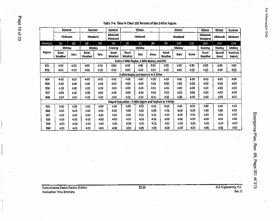
0
-h
A,0
Table 7-4. Time to Clear 100 Percent of the 2-Mile Region
eater "umer Weuther WWathe ritr Weather Evente SummertEnirwee 2-ieiedwe5-ieeeioankP
________ _______ 2-Mile Region, ad-eyhle tego, anile ____ _P__________
R02 4:00 4:00 4:00 4:00 4:00 4:00 I ] 4:00 4:,35 4:00 4:00 4:30 4:00 4:00 I 4:00R05 4:00 4:00 4:00 4:00M4:0 4:00o 4:00 Key 35l to S400 4:M400 4:0e:0R04 4:00 4:00 4:00 4:00 4:00 4:00 4:00 4:35 4:00 4:00 4:'30 4:00 4:00 4:00
R07 4:00 4:0.0 4:00. 4.400 4.:00 4:00 4:00 4:35 4:00 4:00 .4:3.0 4:00. 4:00 4:00ROBl 4:00 4:00 4:00 4:00 4:00 4:00 4:00 4:35 4:00 4:00 4:30 4:00 4:00 4:00
__O___ ___00_ __:0.0 4:00.__ 4;00 d E4 cutio 4:- 2-Mil Rein 4n:Kyol5 Miles 4:_0,_4:__:0 4100._4:0R25 4:00 4:00 4:00 4:00 4:00 4:00 4:00 4:35 4:00 4:00 4:30 4:00 4:00 4:00R26 4:00 4:00g4:00'4:00a4:00 4:0 4:00l Reg3o 4:00eyol 4:0o430 :0M4:0e:0RX5 4:00 4:00 4:00 4:00' 4:00 4:00' 4:00 4:35 4:00 4:00 4:30 4:00 4:00 4:00P,28 4:00 4:00 4:00 4:00 4:00 4:00 .4:00. 4:35 4:00 4:00 4:30 4:00 4:00 4:00R27 4:00 4:00 4:00 4:00 4:00 4:00 4:00 4:35 4:00 4:00 4:30 4:00 4:00 4:00
R30 4:00 4:05 4:00 4:00 4:00 4:00 4:.05 4.:35 4:00 4:006 4.30 4:00 4:00 4:00
-n10.-I
0
0
CD0-u
Co
CD
0
CAoSusquehanna Steam Electric StationEvacuation Time Estimate
ES-16 KLD Engineering, P.C.Rev. 0
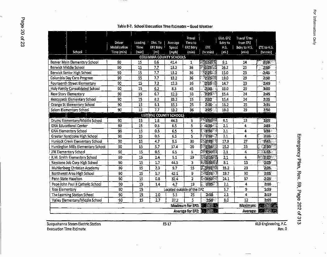
C)0
-h
Table 8-7. School Evacuation Time Estimates - Good Weather
-'1
DJ
'-4.
Duuver Jwrin :lwmen~wryBerwick Middle School I 90 .L .15 7.7 13.2 36 LiI I | I I I II
Berwick Senior High School 90 15 77 13.2 36 •'>Columbia Day Care Program 90 15 7, 13.2 36 ..,'Fourteenthg Streetor aml Eeenay tElmntr Eeenay lmetryCnsEdae Sementarycol coo 09 0 090 90 5 5332 15 1. 1. 837.3 12.3'' 36oreet SretEemnar 0 5 23 '
16.2+•:• 25 .2:5.s+
•i•O: 15. 23 2:45:
•' 19.0 29 2:250 '
19;• .0", 29 3:00.•
2.+25 19.0 29 2i'5O
a a.
SDrums Elementary/Middle School 90 1
GNA Educational Center 90 1GNA Elementary School 90 1Greater Nanticoke High School ! 90 1H unlock Creek Elementary School 90 1Huntington Mills Elementary School 90 1JFK Elementary School 90 1K.M. Smith Elementary School 90 15Keystone Job Corp High School 90 15Muhlenberg Christian Academy 90 •'15"
Northwest Area High. School 90 115Penn State Hazelton 90 1L5
Pope John Paul II Catholic School 90 1
1.80.50.50.54.75.70.52.41.72.35.70.81A
I
21I
21
44.36.56.56.59,517.46.55.1
44.39.742.132.44.7
355530205
293159219
~SO~ 8.1
1~O~ 2.1~ i!:5O-~' 21L~Z:i~5~ ~ 17.9
2~5~ 15.2i~so§~ 2.12~5'~ 21
!i~o~&~ 81~ 15.2~ 19.7~ 24.1
2.1
1344427
434
132330374
2~051':551:551~55
2:30' -
~ '~2:'2O2:052~25~2~252:252:10
ZE m
-I-
CO"13
iCoCD
0o
R ice ElementaryThe Learning Station SchoolValley Elementary/Middle School
I 90 I 15I !
I 90 I 15I I
I *90 I 15
Located ousd fteEPZ572.0 5.1 25 : 21i'J 2.12.7 37.2 5 1 i 1':5+0,-= 8.0
Maximum for EPZ:. 2 •OMaAverage~for EPZ: • A5
9 I412 Iiximum:hveraee:•
[ •.SSj
tII I I
Susquehanna Steam Electric.StationEvacuation Time Estimate
ES-17 KLD Engineering, P.C.Rev. 0
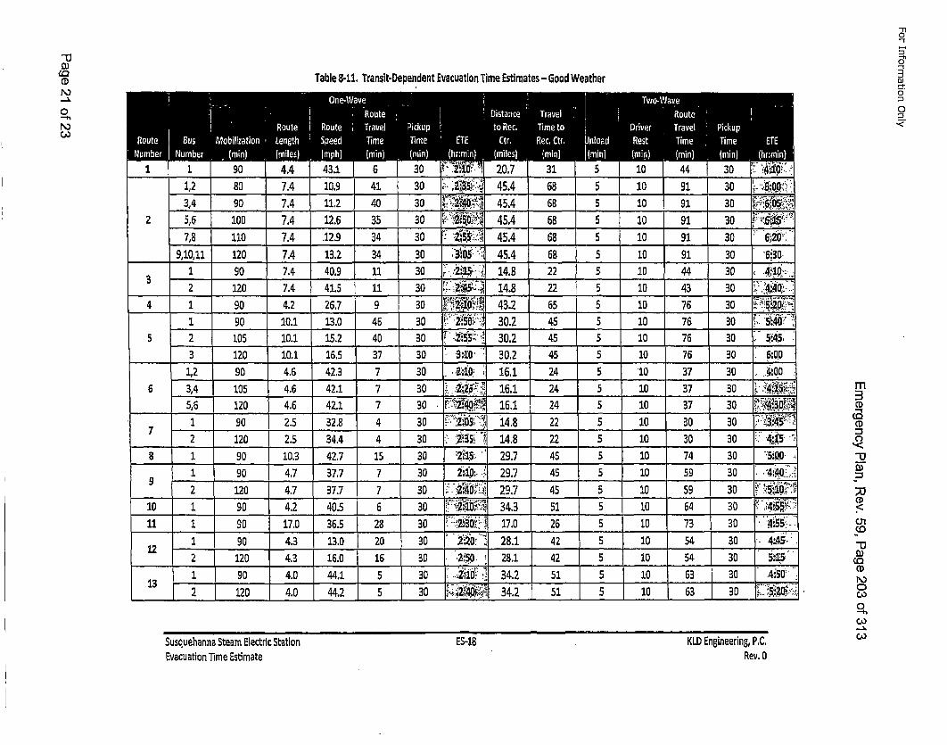
"oCD
0
Table 8-11. Translt-Depandent Evacuation Time Estimates - 6ood Weather
"-Il
0"
o1
0
DJ
1 90 7.4j40.9 11 30 21 148.22. 10 44 0 412 120 7.4 4. 11 30 2;:48 25 0 433'44
4 190 4.2 267 3 •. i. ,vo-: 43.2 655 10 76 30 .....190 10.1 3 .0 4 30 .2.:SO. 30.2 455 10 76 30 :,. 5•:40'
5 2 105 10.1 5. 4 30 255•.• 30.2 45 10 76o30 5'45:3 20 1.1o 6. 3 30 3.10, 30.2 45 5 1 76 30 o.o:.012 90 4.6 42.3 7'3o'20 11 2 5 10 37 30 o. 4 .0O
6 34 105 4.6 4. 7 30 2:5'• 161 2 5 10 37 30 4:5. :''••56 120 4.6 421 7 3 2,•0A 161 2 5 10 37 30 .;4+-.3•0,1 90 2.5 32. 4 30 . 18.2, 10 30 30 ' 3:4:•? :
__ 2 12 I 2. 44 4 30s3 4 22 5 10i• 30 30 L4:_,1s.8 1 90 10.3 427 15 3 "27"1' 29 45S 10 74 30 5:•0.0
1 90 4.7 3,77 30 20: 297-4 5 10 59 30 ,.4:4.:0.9___ 120 1 4.7 37. 7 0 - '2:40•.!" 297 4 10 59 30 "/ " •'5R•10O;"
10 1 90 4.42 405.3 '-2,:10' 33:5 5 10 64 30 4',:4i55•11 1 90 17.0 3. 8 3 .:2,30',": 17S2 10 73 30 ":4!":55
12 90 4.3 130 2,02'20 2.1 4 5 10 54 30 .. 4:.45:
13 90 4.0 4,4.1 0 20 3. 51, 5•: 10 63o30 .4i5so.2 20 4.0 44.2 5 0 2•4. 34,. 2 5 5 10 63 30 °.si•.
m
C1)
,.<
"o
(1).<
01
0CA,
CA,III
I I I I I
Susquehanna Steam Electric StationEvacuation Time Estimate
ES-18 KLD Engineering, PC,Rev. 0
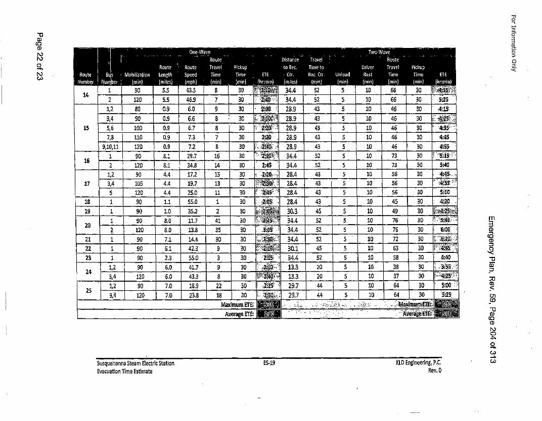
CoCD
'-n
0
0
1 902 120
1,2 80
3,4 9015 5,6 100
7,8 1109,10,1ll 120
1 90162 120
1,2 9017 3,4 105
5 12018 1 90
19 1 901 90
2 .2: 120
21 1 1 9022 1 9023 1 90
24 1,2 903,4 1201,2 90
25 3,4 120
5.5 46.90.9 6.00.9 6.60.9 6.70.9 7.30.9 7.2
i
BA.8.14.44.44.41.11.08,08.0
7.16,12.36.06.07.07.0
29.734.817.219.725.055.0
35,211.713.814,442.355.041.743.318.923.8
43A
9 30 2:OQ 28.9 438 30 28.9 43
7 30 :30 . 28.9 43
16 30~ 2?~0C~34.4 52
11 30~ ' '45:* 28.4 43
30 30 2:30 34.4 52
8 30 133 2022 3 2:2 297 44
18 3 i.25 . 9 44
555555555555555
555S5
10 46 30 i10 46 3 .4.:4.5.•
10 46 30 4:
10 73 30
10 56 3 4:450
10 56 30 5~10, 45 30 :20i
10 76 30 "5:40s"D
C,
.<
oi.
Co
Co
0
,--C,,
LMaximum ETIE::Average. ETh:
,- -..• . *. . aium E E 0
Susquehanna Steam Electric StationEvacuation Time Estimate ES-19 KLD Engineering,. P.C.Rev. 0
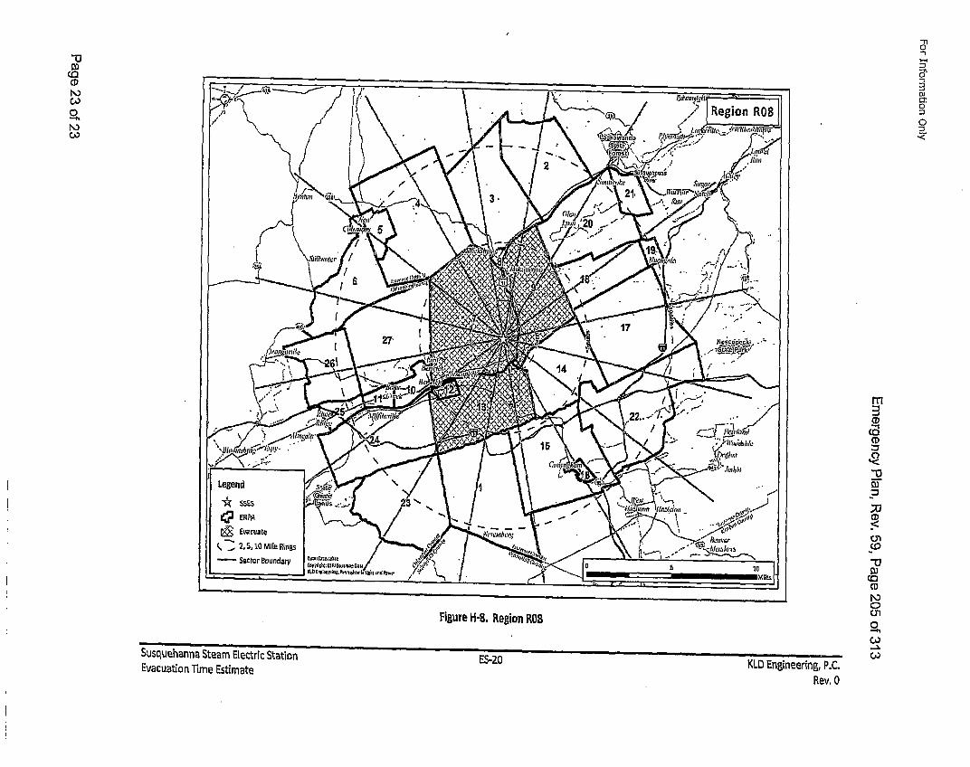
-u3
Co0
-hN)
"1
O3J
0
0
CD
CD
C,
-v
CD
v-iCo
Co
CoFigure H-B, Region ROB
Susquehanna Steam Electric Station n ,
Evacuation Time Estimater'o-/..U KLD Eng~ineering, P.C.
Rev. 0
For Information Only
Emegeny lan Re. 9, age20 of31
APPENDIX H
DOWNSTREAM SUSQUEHANNA RIVER WATER USAGE
Page 1 of 3
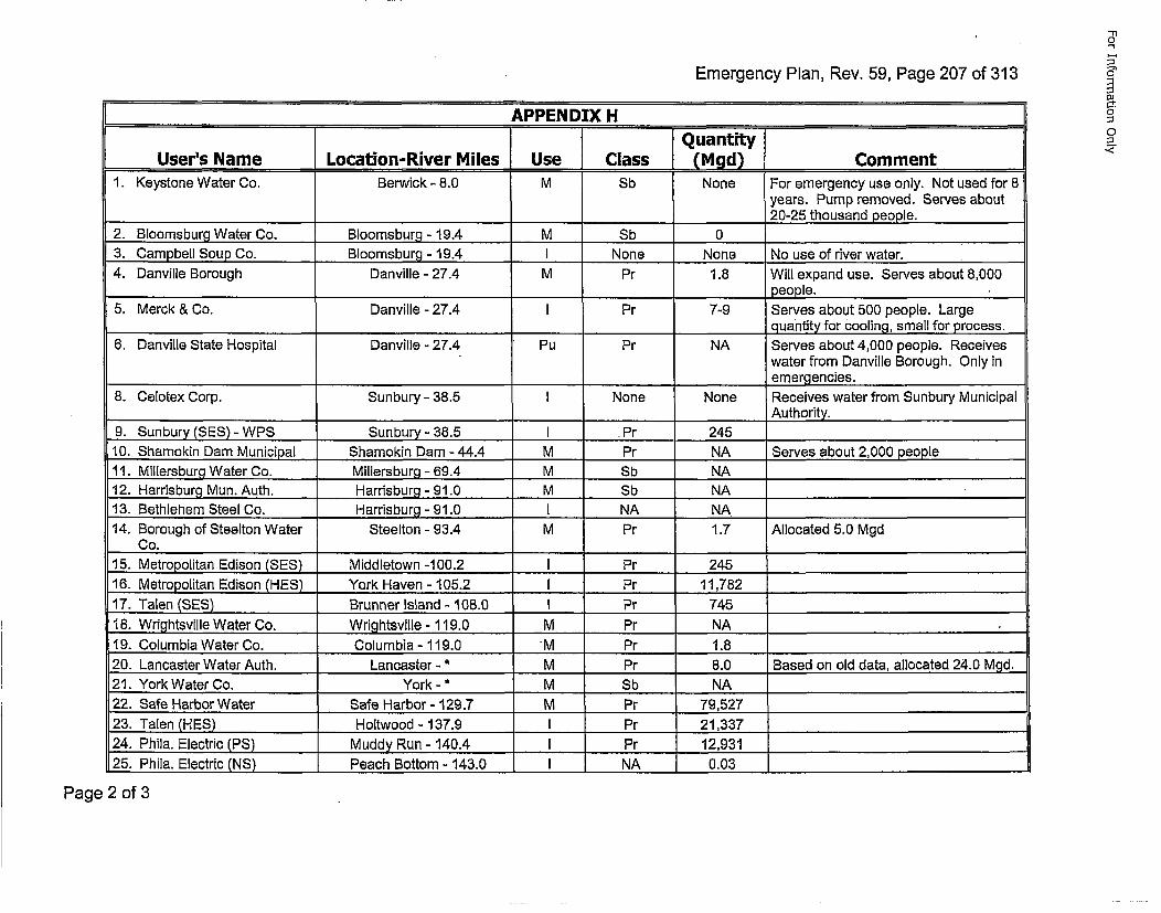
Emerenc PlaIRv. 5,rPge 27 o 31
"1I0
5"
O-t
0
0,
Aflfl~fliEY~ LI
1 I I iQuantitylUser's Name JLocation-River Miles Use Class JAM9d) Comment.
1. Keystone Water Co. Berwick - 8.0 M Sb None For emergency use only. Not used for 8years. Pump removed. Serves about
_____________________ _________20-25 thousand people.2. Bloomsburg Water Co. Bloomsburg - 19.4 M Sb 03. Campbell Soup Co. Bloomsburg - 19.4 I None None No use of river water.4. Danville Borough Danville - 27.4 M Pr 1.8 Will expand use. Serves about 8,000
______________________ _________ people.5. Merck & Co. Danville - 27.4 I Pr 7-9 Serves about 500 people. Large
____ ____quantity for cooling, small for process.6. Danville State Hospital Danville - 27.4 Pu Pr NA Serves about 4,000 people. Receives
water from Danville Borough. Only in. emergencies.
8. Celotex Corp. Sunbury - 38.5 I None None Receives water from Sunbury Municipal
9. Sun bury (SES) - WPS Sun bury - 38.5 I Pr 24510.. Shamokin Dam Municipal Shamokin Dam -44.4 M Pr NA Serves about 2,000 people11. Millersburg Water Co. Millersburg - 69.4 M Sb NA _________________
12. Harrisburg Mun. Auth. Harrisburg -91.0 ... M Sb NA ________________
13. Bethlehem Steel Co. Harrisburg -91.0 I. NA NA ________________
14. Borough of Steelton Water Steelton - 93.4 M Pr 1.7 Allocated 5.0 MgdCo. _ _ _ _ _ _ _ _ _ _ _ _ _ _ _ _ _ _ _ _ _ _ _
15. Metropolitan Edison (SES) Middletown -100.2 I Pr 24516. Metropolitan Edison (HES) York Haven - 105.2 I Pr 11,75217. Talen (SES) Brunner Island - 108.0 1 Pr 745 ________________
18. Wrightsville Water Co. Wrig1htsville - 119.0 M Pr NA __________________
19. Columbia Water Co. Columbia - 119.0 M Pr 1.8 _________________
20. Lancaster Water Auth. Lancaster - * M Pr 8.0 Based on old data, allocated 24.0 Mgd.21. York Water Co. York -* M Sb NA ______________
22. Safe Harbor Water Safe Harbor - 129.7 M Pr 79,527 _______________
23. Talen (HES) Holtwood - 137.9 I Pr 21,337 _______________
24. Phila. Electric (PS) Muddy Run - 140.4 I Pr 12,93125. Phila. Electric (NS) Peach Bottom - 143.0 I NA 0.03 _________________
Page 2 of 3
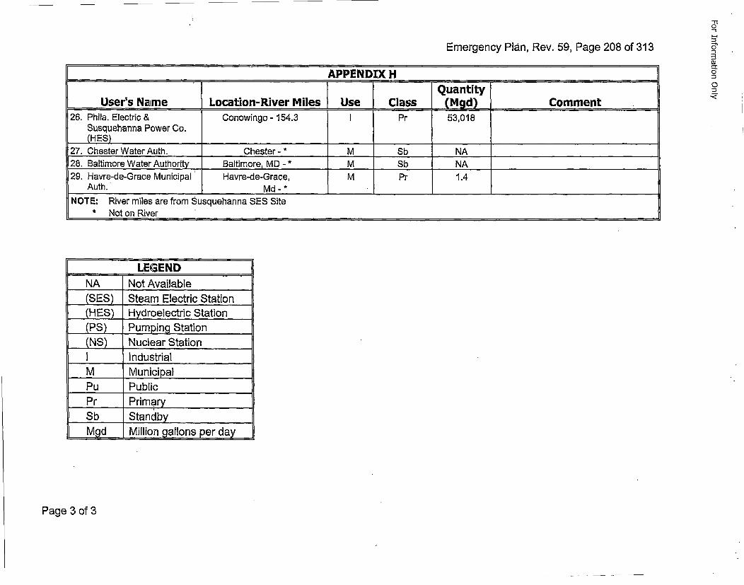
Emergency Plan, Rev. 59, Page 208 of 313
"11o
-4.
User's Name ILocation-River Miles Use Class L Mgdi Comment26. Phila. Electric & Conowingo - 154.3 I Pr 53,018
Susquehanna Power Co.(H.E.S)__ _ _ _ _ _ _ _ _ _
27. Chester Water Auth. Chester - * M Sb NA28. Baltimore Water Authority Baltimore, MD - * M Sb NA29. Havre-de-Grace Municipal' Havre-de-Grace, M Pr 1.4
Auth. Md* -_ _ *_ _ _ _ _ _ _ _ _ __ _ _ _ _ _ _
NOTE: River miles are from Susquehanna SES Site• Not on River
______ LEGENDNA Not Available(SES) Steam Electric Station.(HES) HyIdroelectric Station(PS) Pumping Station(NS) Nuclear Station
1IndustrialM MunicipalPu PublicPr PrimarySb Standby_Mgd Million gallons per day
Page 3 of 3
For Information Only
Emergency Plan, Rev. 59, Page 209 of 313
APPENDIX IPOPULATION UPDATE FOR SSES
EMERGENCY PLANNING ZONE
Page 1 of 2
For Information Only
Emergency Plan, Rev. 59, Page 210 of 313
REFER TO THE EVACATION TIME ESTIMATE IN APPENDIX G FOR THE CURRENTPOPULATION INFORMATION
Page 2 of 2
FodrInformation Only
Emergency Plan, Rev. 59, Page 211 of 313
APPENDIX J
NUREG-0654 PLANNING STANDARDS AND
EVALUATION CRITERIA CROSS
REFERENCE TO SSES EMERGENCY PLAN
Page 1 ofl10
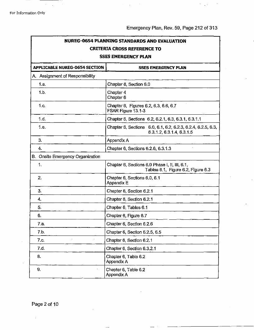
For Information Only
Emergency Plan, Rev. 59, Page 212 of 313
NUREG-0654 PLANNING STANDARDS AND EVALUATION
CRITERIA CROSS REFERENCE TO
SSES EMERGENCY PLAN
APPLICABLE NUREG-0654 SECTION SSES EMERGENCY PLAN
A. Assignment of Responsibility ________________________
l.a. Chapter 6, Section 6.0
1 .b. Chapter 4__________________________Chapter 6
I .c. Chapter 6, Figures 6.2, 6.3, 6.6, 6.7FSAR Figure 13.1-3
I1.d. Chapter 6, Sections 6.2, 6.2,1, 6.3, 6.3.1, 6.3.1.1
I.e. Chapter 6, Sections 6.0, 6.1, 6.2, 6.2.3, 6.2.4, 6.2.5, 6.3,6.3.1.2, 6.3.1.4, 6.3.1.5
3. Appendix A
4. Chapter 6, Sections 6.2.6, 6.3.1.3
B. Onsite Emergency Organization
1. Chapter 6, Sections 6.0 Phase I, HI, III, 6.1,Tables 6.1, Figure 6.2, Figure 6.3
2. :Chapter 6, Sections 6.0, 6.1
Appendix E
3. Chapter 6, Section 6.2.1
4. Chapter 6, Section 6.2.1
5. Chapter 6, Tables 6.1
6. Chapter 6, Figure 6.7
7.a. Chapter 6, Section 6.2.6
7.b. Chapter 6, Section 6.2.5, 6.5
7.c. Chapter 6, Section 6.2.1
7.d. Chapter 6, Section 6.3.2.1
8. Chapter 6, Table 6.2Appendix A
9. Chapter 6, Table 6.2_________________________ Appendix A
Page 2 of 10
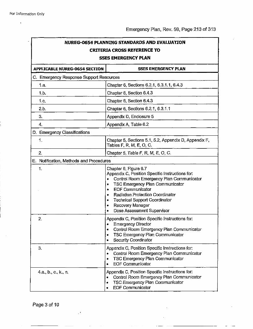
For Information Only
Emergency Plan, Rev. 59, Page 213 of 313
NUREG-0654 PLANNING STANDARDS AND EVALUATION
CRITERIA CROSS REFERENCE TO
SSES EMERGENCY PLAN
APPLICABLE NUREG-0654 SECTION ISSES EMERGENCY PLAN
C. Emergency Response Support Resourcesl.a. Chapter 6, Sections 6.2.1, 6.3.1.1, 6.4.3
1.b. Chapter 6, Section 6.4.3
1 .c. Chapter 6, Section 6.4.3
2.b. Chapter 6, Sections 6.2.1, 6.3.1.1
3. Appendix D, Enclosure 5
4. Appendix A, Table 6.2
D. Emergency Classifications
1. Chapter 5, Sections 5.1, 5.2, Appendix D, Appendix F,Tables F, R, M, E, 0, C.
2. Chapter 5, Table F, R, M, E, 0, C.
E. Notification, Methods and Procedures
1. Chapter 6, Figure 6.7Appendix C, Position Specific Instructions for:* Control Room Emergency Plan Communicator* TSC Emergency Plan Communicator* EOF Communicator* Radiation Protection Coordinator* Technical Support Coordinator* Recovery Manager• Dose Assessment Supervisor
2. Appendix C, Position Specific instructions for:* Emergency Director* Control Room Emergency Plan Communicator* TSC Emergency Plan Communicator* Security Coordinator
3. Appendix C, Position Specific Instructions for:* Control Room Emergency Plan Communicator* TSC Emergency Plan Communicator* EOF Communicator
4.a., b., c., k., n. Appendix C, Position Specific Instructions for:*, Control Room Emergency Plan Communicator* TSC Emergency Plan Communicator* EOF Communicator
Page 3 of 10
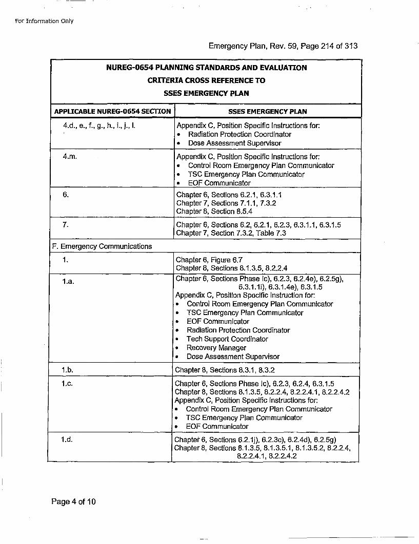
For Information Only
Emergency Plan, Rev. 59, Page 214 of 313
NUREG-0654 PLANNING STANDARDS AND EVALUATION
CRITERIA CROSS REFERENCE TO
SSES EMERGENCY PLAN
APPLICABLE NUREG-0654 SECTION SSES EMERGENCY PLAN
4.d., e., f., g., h., i., j., I. Appendix C, Position Specific Instructions for:* Radiation Protection Coordinator• Dose Assessment Supervisor
4.m. Appendix C, Position Specific Instructions for:* Control Room Emergency Plan Communicator* TSC Emergency Plan Communicator* EQF Communicator
6. Chapter 6, Sections 6.2.1, 6.3.1.1Chapter 7, Sections 7.1.1, 7.3.2Chapter 8, Section 8.5.4
7. IChapter 6, Sections 6.2, 6.2.1, 6.2.3, 6.3.1.1, 6.3.1.5
Chapter 7, Section 7.3.2, Table 7.3
F. Emergency Communications
1. Chapter 6, Figure 6.7_________________________Chapter 8, Sections 8.1.3.5, 8.2.2.4
l.a. Chapter 6, Sections Phase Ic), 6.2.3, 6.2.4e), 6.2.5g),6.3.1.1i), 6.3.1.4e), 6.3.1.5
Appendix C, Position Specific Instruction for:* Control Room Emergency Plan Communicatora TSC Emergency Plan Communicator* EOF Communicator* Radiation Protection Coordinator* Tech Support Coordinator* Recovery Manager* Dose Assessment Supervisor
1 .b. ;Chapter 8, Sections 8.3.1, 8.3.2
1 .c. Chapter 6, Sections Phase Ic), 6.2.3, 6.2.4, 6.3.1.5Chapter 8, Sections 8.1.3.5, 8.2.2.4, 8.2.2.4.1, 8.2.2.4.2Appendix C, Position Specific Instructions for:* Control Room Emergency Plan Communicator* TSC Emergency Plan Communicator* EOF Communicator
1l.d. Chapter" 6, Sections 6.2.1j), 6.2.3c), 6.2.4d), 6.2.5g)Chapter 8, Sections 8.1.3.5, 8.1.3.5.1, 8.1.3.5.2, 8.2.2.4,
8.2.2.4.1, 8.2.2.4.2
Page 4 of 10
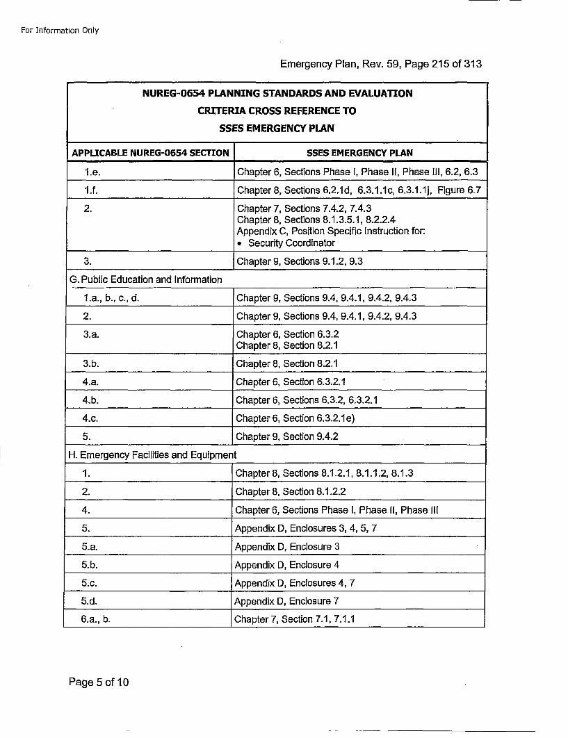
For Information Only
Emergency Plan, Rev. 59, Page 215 of 313
NUREG-0654 PLANNING STANDARDS AND EVALUATION
CRITERIA CROSS REFERENCE TO
SSES EMERGENCY PLAN
APPLICABLE NUREG-0654 SECTION SSES EMERGENCY PLAN
1 .e. Chapter 6, Sections Phase I, Phase II, Phase 111, 6.2, 6.3
1 .f. Chapter 8, Sections 6.2.1d, 6.3.1.1c, 6.3.1.1j, Figure 6.7
2. Chapter 7, Sections 7.4.2, 7.4.3Chapter 8, Sections 8.1.3.5.1, 8.2.2.4Appendix C, Position Specific Instruction for:
_________________________ Security Coordinator
3. Chapter 9, Sections 9.1.2, 9.3
G. Public Education and Information
l.a., b., c., d. Chapter 9, Sections 9.4, 9.4.1, 9.4.2, 9.4.3
2. Chapter 9, Sections 9.4, 9.4.1, 9.4.2, 9.4.3
3.a. Chapter 6, Section 6.3.2Chapter 8, Section 8.2.1
3.b. chapter 8, Section 8.2.1
4.a. Chapter 6, Section 6.3.2.1
4.b. Chapter 6, Sections 6.3.2, 6.3.2.1
4.c. Chapter 6, Section 6.3.2.1e)
5. Chapter 9, Section 9.4.2
H. Emergency Facilities and Equipment
1. Chapter 8, Sections 8.1.2.1, 8.1.1.2, 8.1.3
2. Chapter 8, Section 8.1.2.2
4. Chapter 6, Sections Phase I, Phase II, Phase 1l1
5. Appendix D, Enclosures 3, 4,5, 7
5.a. Appendix D, Enclosure 3
5.b. Appendix D, Enclosure 4
5.c. Appendix D, Enclosures 4, 7
5.d. Appendix 0, Enclosure 7
6.a., b. Chapter 7, Section 7.1, 7.1.1
Page 5 of 10
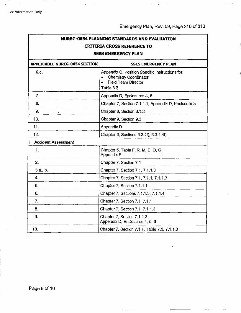
For Information Only
Emergency Plan, Rev. 59, Page 216 of 313
NUREG-0654 PLANNING STANDARDS AND EVALUATION
CRITERIA CROSS REFERENCE TO
SSES EMERGENCY PLAN
APPLICABLE NUREG-0654 SECTION SSES EMERGENCY PLAN
6.c. Appendix C, Position Specific Instructions for:* Chemistry Coordinator* Field Team DirectorTable 6.2
7. Appendix D, Enclosures 4, 5
8. Chapter 7, Section 7.1.1.1, Appendix 0, Enclosure 3
9. Chapter 8, Section 8.1.2
10. Chapter 9, Section 9.3
11. Appendix D
12. Chapter 6, Sections 6.2.4f), 6.3.1.40
I. Accident Assessment
1. Chapter 5, Table F, R, M, E, 0, CAppendix F
2. Chapter 7, Section 7.1
3.a., b. Chapter 7, Section 7.1, 7.1.1.3
4. Chapter 7, Section 7.1, 7.1.1, 7.1.1.3
5. Chapter 7, Section 7.1.1.1
6. Chapter 7, Sections 7.1.1.3, 7.1.1.4
7. Chapter 7, Section 7.1, 7.1.1
8. Chapter 7, Section 7.1, 7.1.1.3
9. Chapter 7, Section 7.1.1.3Appendix 0, Enclosures 4, 5, 6
10. Chapterl7, Section 7.1.1, Table 7.3, 7.1.1.3
Page 6 of 10
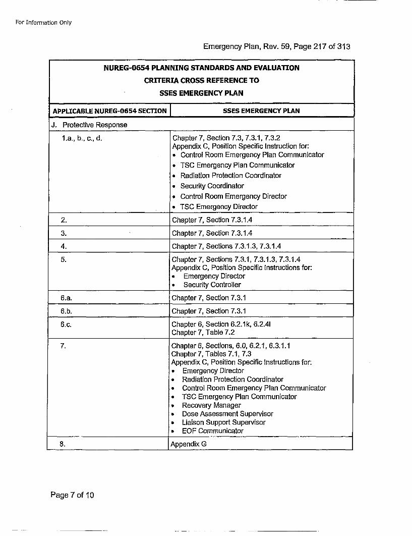
For Information Only
Emergency Plan, Rev. 59, Page 217 of 313
NUREG-0654 PLANNING STANDARDS AND EVALUATION
CRITERIA CROSS REFERENCE TO
SSES EMERGENCY PLAN
APPLICABLE NUREG-0654 SECTION SSES EMERGENCY PLAN
J. Protective Response
l.a., b., c., d. Chapter 7, Section 7.3, 7.3.1, 7.3.2Appendix C, Position Specific Instruction for:* Control Room Emergency Plan Communicator
* TSC Emergency Plan Communicator
* Radiation Protection Coordinator
* Security Coordinator
* Control Room Emergency Director
* TSC Emergency Director
2. Chapter 7, Section 7.3.1.4
3. Chapter 7, Section 7.3.1.4
4. Chapter 7, Sections 7.3.1.3, 7.3.1.4
5. Chapter 7, Sections 7.3.1, 7.3.1.3, 7.3.1.4Appendix C, Position Specific Instructions for:* Emergency Director* Security Controller
6.a. Chapter 7, Section 7.3.1
6.b. Chapter 7, Section 7.3.1
6. c. Chapter 6, Section 6.2.1k, 6.2.41__________________________Chapter 7, Table 7.2
7. Chapter 6, Sections, 6.0, 6.2.1, 6.3.1.1Chapter 7, Tables 7.1, 7.3Appendix C, Position Specific Instructions for:
•Emergency Director* Radiation Protection Coordinator* Control Room Emergency Plan Communicator* TSC Emergency Plan Communicator* Recovery Manager* Dose Assessment Supervisor• Liaison Support Supervisor• EOF Communicator
8. Appendix G
Page 7 of 10
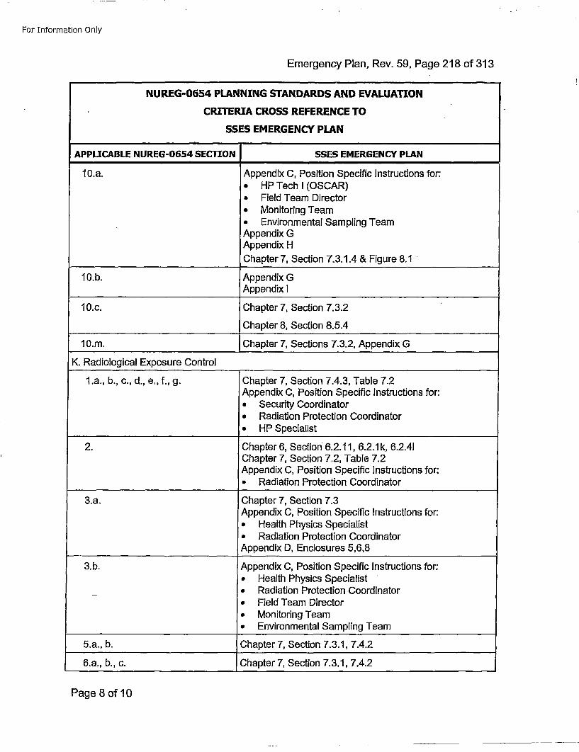
For Information Only
Emergency Plan, Rev. 59, Page 218 of 313
NUREG-0654 PLANNING STANDARDS AND EVALUATION
CRITERIA CROSS REFERENCE TO
SSES EMERGENCY PLAN
APPLICABLE NUREG-0654 SECTION SSES EMERGENCY PLAN
10.a. Appendix C, Position Specific Instructions for:* HP TechlI(OSCAR)* Field Team Director* Monitoring Team* Environmental Sampling TeamAppendix GAppendix HChapter 7, Section 7.3.1.4 & Figure 8.1
10.b. Appendix GAppendix I
10.c. Chapter 7, Section 7.3.2
Chapter 8, Section 8.5.4
10.m. Chapter 7, Sections 7.3.2, Appendix G
K. Radiological Exposure Control
1l.a., b., c., d., e., f., g. Chapter 7, Section 7.4.3, Table 7.2Appendix C, Position Specific Instructions for:* Security Coordinator* Radiation Protection Coordinator* HP Specialist
2. Chapter 6, Section 6.2.11, 6.2.1k, 6.2.41Chapter 7, Section 7.2, Table 7.2Appendix C, Position Specific instructions for:* Radiation Protection Coordinator
3.a. Chapter 7, Section 7.3Appendix C, Position Specific Instructions for:• Health Physics Specialist* Radiation Protection CoordinatorAppendix 0, Enclosures 5,6,8
3.b. Appendix C, Position Specific Instructions for:* Health Physics Specialist* Radiation Protection Coordinator* Field Team Director* Monitoring Team• Environmental Sampling Team
5.a., b. Chapter 7, Section 7.3.1, 7.4.2
6.a., b., c. Chapter 7, Section 7.3.1, 7.4.2
Page 8 of 10
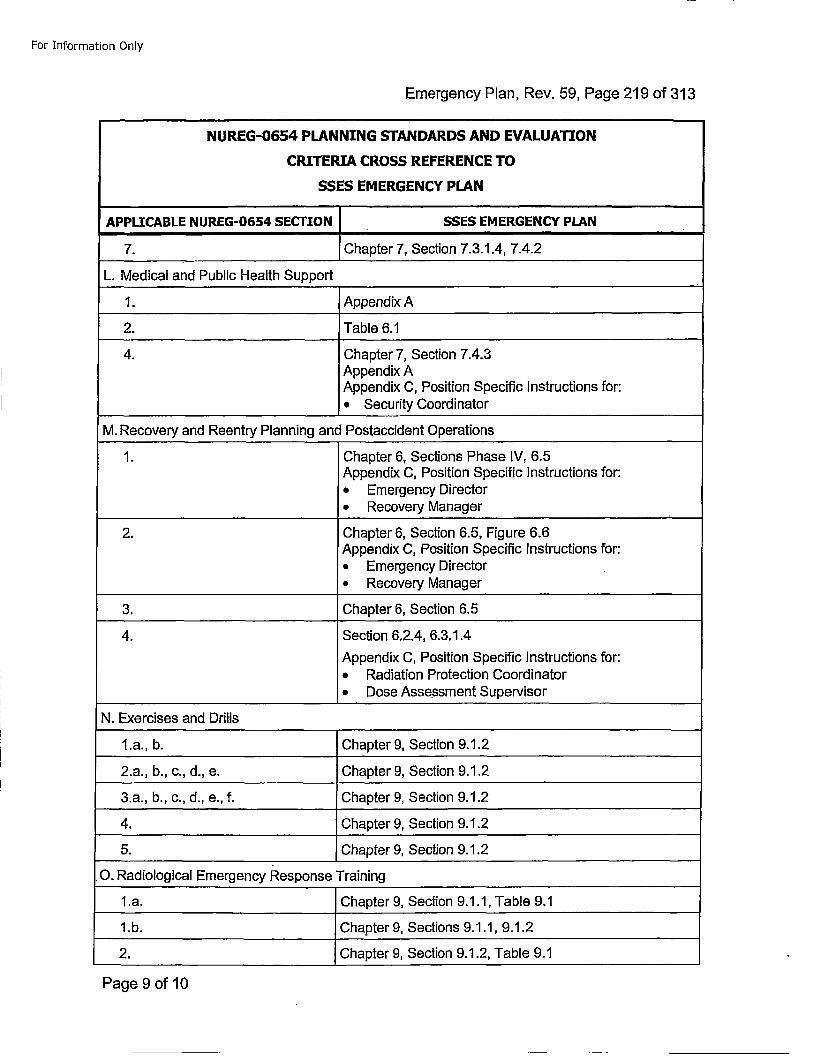
For Information Only
Emergency Plan, Rev. 59, Page 219 of 313
NUREG-0654 PLANNING STANDARDS AND EVALUATION
CRITERIA CROSS REFERENCE TO
SSES EMERGENCY PLAN
APPLICABLE NUREG-0654 SECTION I-SSEs EMERGENCY PLAN
7. hptr7, Section 7.3.1.4, 7.4.2
L. Medical and Public Health Support
1. Appendix A
2. Table 6.1
4. Chapter 7, Section 7.4.3Appendix AAppendix C, Position Specific Instructions for:* Security Coordinator
M. Recovery and Reentry Planning and Postaccident Operations
1. Chapter 6, Sections Phase IV, 6.5Appendix C, Position Specific Instructions for:* Emergency Director* Recovery Manager
2. Chapter 6, Section 6.5, Figure 6.6Appendix C, Position Specific instructions for:* Emergency Director* Recovery Manager
3. Chapter 6, Section 6.5
4. Section 6.2.4, 6.3.1.4
Appendix C, Position Specific Instructions for:• Radiation Protection Coordinator* Dose Assessment Supervisor
N. Exercises and Drills
1l.a., b. Chapter 9, Section 9.1.2
2.a., b., c., d., e. Chapter 9, Section 9.1.2
3.a., b., c., d., e., f. Chapter 9, Section 9.1.2
4. Chapter 9, Section 9.1.2
5. Chapter 9, Section 9.1.2
0. Radiological Emergency Response Training
l.a. Chapter 9, Section 9.1.1, Table 9.1
1.b. Chapter 9, Sections 9.1.1, 9.1.2
2. Chapter 9, Section 9.1.2, Table 9.1
Page 9 of 10
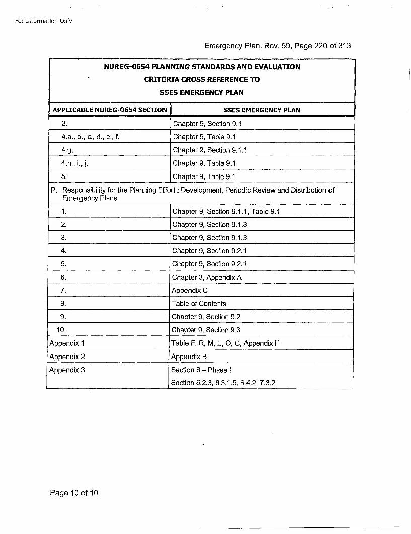
For Information Only
Emergency Plan, Rev. 59, Page 220 of 313
NUREG-0654 PLANNING STANDARDS AND EVALUATION
CRITERIA CROSS REFERENCE TO
SSES EMERGENCY PLAN
APPLICABLE NUREG-0654 SECTION SSES EMERGENCY PLAN
3. Chapter 9, Section 9.1
4.a., b., c., d., e., f. Chapter 9, Table 9.1
4.g. Chapter 9, Section 9.1.1
4.h., i., j. Chapter 9, Table 9.1
5. Chapter 9, Table 9.1
P. Responsibility for the Planning Effort : Development, Periodic Review and Distribution ofEmergency Plans
1. Chapter 9, Section 9.1.1, Table 9.1
2. Chapter 9, Section 9.1.3
3. Chapter 9, Section 9.1.3
4. Chapter 9, Section 9.2.1
5. Chapter 9, Section 9.2.1
6. Chapter 3, Appendix A
7. Appendix C
8. Table of Contents
9. Chapter 9, Section 9.2
10. Chapter 9, Section 9.3
Appendix 1 Table F, R, M, E, 0, C, Appendix F
Appendix 2 Appendix B
Appendix 3 Section 6 - Phase I
Section 6.2.3, 6.3.1.5, 6.4.2, 7.3.2
Page 10 of 10
For Information Only
Emergency Plan, Rev. 59, Page 221 of 313On-Shift Staffing Analysis
APPENDIX KOn-Shift Staffing Analysis
Page 1 of 93
For Information Only
Emergency Plan, Rev. 59, Page 222 of 313On-Shift Staffing Analysis
Susqueha~nna Stearnin Eliec~tri Station
Onf--,Shift Sta~ffing An~a~lysis ReportRevision 0
December 14, 201!2
Page 2 of 93
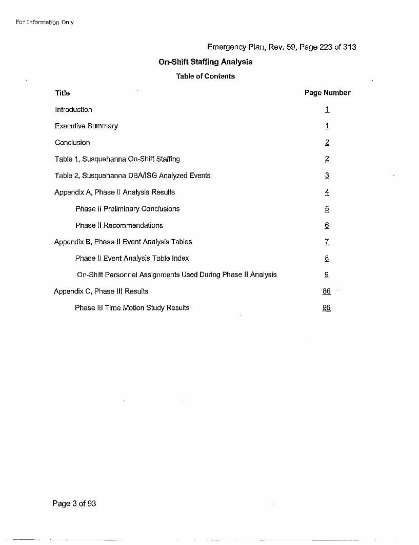
For Information Only
Emergency Plan, Rev. 59, Page 223 of 313On-Shift Staffing Analysis
Table of Contents
Title
Introduction
Executive Summary
Conclusion
Table 1, Susquehanna On-Shift Staffing
Table 2, Susquehanna DBAIISG Analyzed Events
Appendix A, Phase II Analysis Results
Phase II Preliminary Conclusions
Phase II Recommendations
Appendix B, Phase II Event Analysis Tables
Phase Ii Event Analysis Table Index
On-Shift Personnel Assignments Used During Phase II Analysis
Appendix C, Phase IIl Results
Phase Ill Time Motion Study Results
Page Number
1
1
2_
2
_3
4
_5
6
7
_8
9
86
95
Page 3 of 93
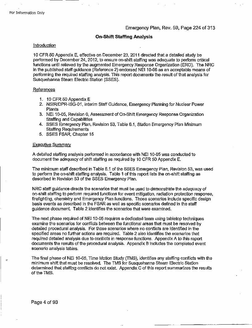
For Information Only
Emergency Plan, Rev. 59, Page 224 of 313
On-Shift Staffing Analysis
Introduction
10 CFR 50 Appendix E, effective on December 23, 2011 directed that a detailed study beperformed by December 24, 2012, to ensure on-shift staffing was adequate to perform criticalfunctions until relieved by the augmented Emergency Response Organization (ERO). The NRCin the published staff guidance (Reference 2) endorsed NEI 10-05 as an acceptable means ofperforming the required staffing analysis. This report documents the result of that analysis forSusquehanna Steam Electric Station (SSES).
References
1. 10OCFR 50Appendix E2. NSIR/DPR-ISG-01, Interim Staff Guidance, Emergency Planning for Nuclear Power
Plants3. NEI 10-05, Revision 0, Assessment of On-Shift Emergency Response Organization
Staffing and Capabilities4. SSES Emergency Plan, Revision 53, Table 6.1, Station Emergency Plan Minimum
Staffing Requirements5. SSES FSAR, Chapter 15
Executive Summary
A detailed staffing analysis performed in accordance with NE! 10-05 was conducted todocument the adequacy of shift staffing as required by 10 CFR 50 Appendix E.
The minimum staff described in Table 6.1 of the SSES Emergency Plan, Revision 53, was usedto perform the on-shift staffing analysis. Table 1 of this report lists the on-shift staffing asdescribed in Revision 53 of the SSES Emergency Plan.
NRC staff guidance directs the scenarios that must be used to demonstrate the adequacy ofon-shift staffing to perform required functions for event mitigation, radiation protection response,firefighting, chemistry and Emergency Plan functions. Those scenarios include specific designbasis events as described in the FSAR as well as specific scenarios defined in the staffguidance document. Table 2 identifies the scenarios that were examined.
The next phase required of NEI 10-05 requires a dedicated team using tabletop techniquesexamine the scenarios for conflicts between the functional areas that must be resolved bydetailed procedural analysis. For those scenarios where no conflicts are identified in thespecified areas no further actions are required. Table 2 also identifies the scenarios thatrequired detailed analysis due to conflicts in response functions. Appendix A to this reportdocuments the results of the procedural analysis. Appendix B includes the completed eventscenario analysis tables.
The final phase of NEI 10-05, Time Motion Study (TMS), identifies any staffing conflicts with theminimum shift that must be resolved. The TMS for Susquehanna Steam Electric Stationdetermined that staffing conflicts do not exist. Appendix C of this report summarizes the resultsof the TMS.
Page 4 of 93
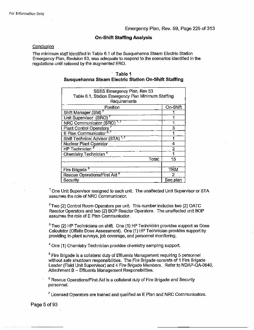
For Information Only
Emergency Plan, Rev. 59, Page 225 of 313
On-Shift Staffing Analysis
Conclusion
The minimum staff identified in Table 6.1 of the Susquehanna Steam Electric StationEmergency Plan, Revision 53, was adequate to respond to the scenarios identified in theregulations until relieved by the augmented ERO.
Table 1Susquehanna Steam Electric Station On-Shift Staffing
SSES Emergency Plan, Rev 53Table 6.1, Station Emergency Plan Minimum Staffing
Requirements_____Position On-Shift
Shift Manager (SM) 7 1 __
Unit Supervisor (SRO) 7 1 __
NRC Communicator (SRO) 1, 7 1Plant Control Operators ~'3 _
E Plan Communicator 2,7 1 __
Shift Technical Advisor (STA) 1,.7 1 __
Nuclear Plant Operator 4HP Technician 3 2Chemistry Technician 1
Total: 15
Fire Brigade 5 TRMRescue Operations/First Aid 6 2Security Sec plan
1 One Unit Supervisor assigned to each unit. The unaffected Unit Supervisor or STAassumes the role of NRC Communicator.
2Two (2) Control Room Operators per unit. This number includes two (2) OATCReactor Operators and two (2) BOP Reactor Operators. The unaffected unit BOPassumes the role of E Plan Communicator.
3 Two (2) HP Technicians on shift. One (1) HP Technician provides support as DoseCalculator (Offsite Dose Assessment). One (1) HP Technician provides support byproviding In-plant surveys, job coverage, and personnel monitoring.
'4 One (1) Chemistry Technician provides chemistry sampling support.
5 Fire Brigade is a collateral duty of Effluents Management requiring 5 personnelwithout safe shutdown responsibilities. The Fire Brigade consists of 1 Fire BrigadeLeader (Field Unit Supervisor) and 4 Fire Brigade Members. Refer to NDAP-QA-0640,Attachment B - Effluents Management Responsibilities.
6 Rescue Operations/First Aid is a collateral duty of Fire Brigade and Securityperson nel.
7 Licensed Operators are trained and qualified as E Plan and NRC Communicators.
Page 5 of 93
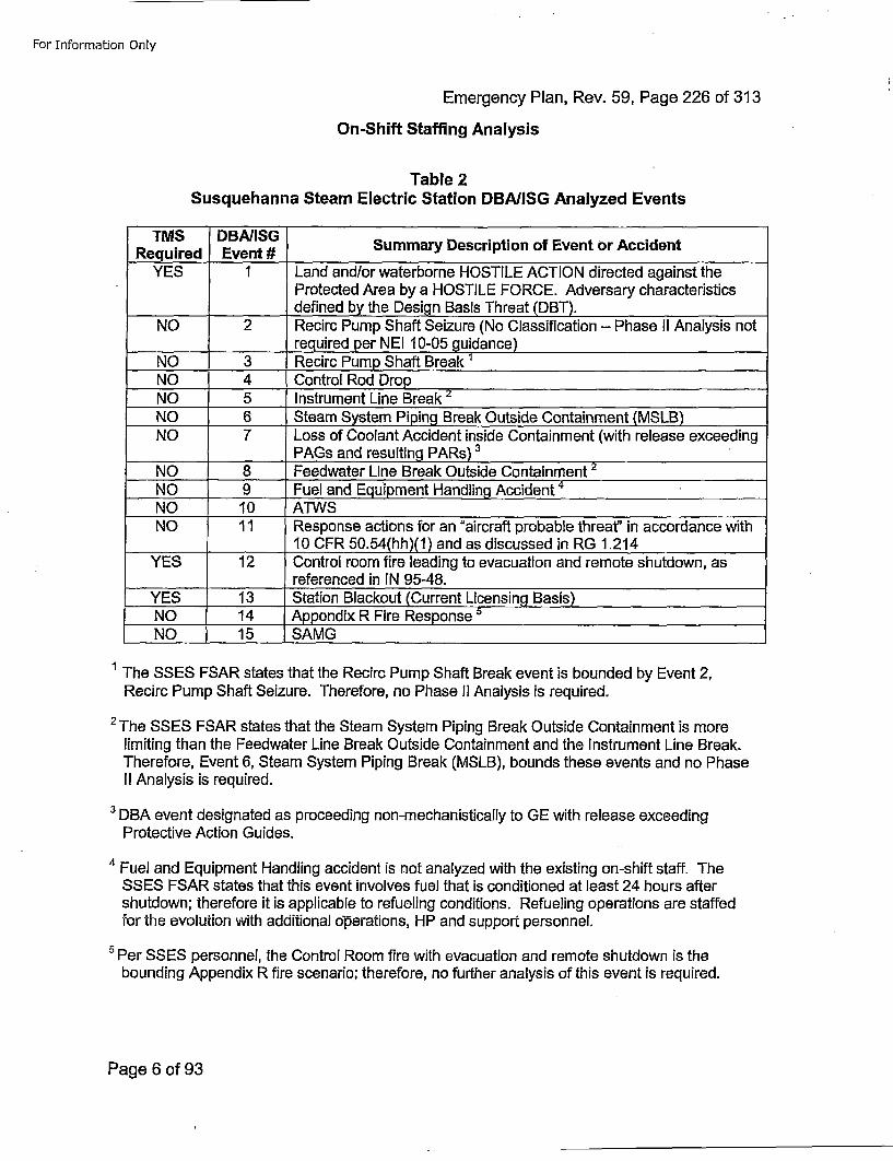
For Information Only
Emergency Plan, Rev. 59, Page 226 of 313
On-Shift Staffing Analysis
Table 2Susquehanna Steam Electric Station DBA/ISG Analyzed Events
Rqired DventSG Summary Description of Event or Accident
YES 1 Land and/or waterborne HOSTILE ACTION directed against theProtected Area by a HOSTILE FORCE. Adversary characteristics
________________defined by the Design Basis Threat (DBT).NO 2 Recirc Pump Shaft Seizure (No Classification - Phase II Analysis not
________required per NEI 10-05 guidance)NO 3 Recirc Pump Shaft Break 1
NO 4 Control Rod DropNO 5 Instrument Line BreakNO 6 Steam System Piping Break Outside Containment (MSLB)NO 7 Loss of Coolant Accident inside Containment (with release exceeding
PAGs and resulting PARs) 3
NO 8 Feedwater Line Break Outside Containment 2
NO 9 Fuel and Equipment Handling AcienNO 10 ATWSNO 11 Response actions for an "aircraft probable threat" in accordance with
________10 CFR 50.54(hh)(1) and as discussed in RG 1.214YES 12 Control room fire leading to evacuation and remote shutdown, as
referenced in IN 95-48.YES 13 Station Blackout (Current Licensing Basis)NO 14 Appendix R Fire Response 5
NO 15 ISAMG
1 The SSES FSAR states that the Recirc Pump Shaft Break event is bounded by Event 2,Recirc Pump Shaft Seizure. Therefore, no Phase II Analysis is required.
2 The SSES FSAR states that the Steam System Piping Break Outside Containment is morelimiting than the Feedwater Line Break Outside Containment and the Instrument Line Break.Therefore, Event 6, Steam System Piping Break (MSLB), bounds these events and no PhaseII Analysis is required.
3 DBA event designated as proceeding non-mechanistically to GE with release exceedingProtective Action Guides.
4' Fuel and Equipment Handling accident is not analyzed with the existing on-shift staff. TheSSES FSAR states that this event involves fuel that is conditioned at least 24 hours aftershutdown; therefore it is applicable to refueling conditions. Refueling operations are staffedfor the evolution with additional operations, HP and support personnel.
SPrSSES personnel, the Control Room fire with evacuation and remote shutdown is thebounding Appendix R fire scenario; therefore, no further analysis of this event is required.
Page 6 of 93

For Information Only
Emergency Plan, Rev. 59, Page 227 of 313
On-Shift Staffing Analysis
Appendix APhase II Analysis Results
Page 7 of 93
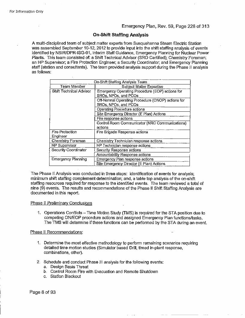
For Information Only
Emergency Plan, Rev. 59, Page 228 of 313
On-Shift Staffing Analysis
A multi-disciplined team of subject matter experts from Susquehanna Steam Electric Stationwas assembled September 10-12, 2012 to provide input into the shift staffing analysis of eventsidentified by NSIRIDPR-ISG-01, Interim Staff Guidance, Emergency Planning for Nuclear PowerPlants. This team consisted of: a Shift Technical Advisor (SRO Certified); Chemistry Foreman;an HP Supervisor; a Fire Protection Engineer; a Security Coordinator; and Emergency Planningstaff (station and consultants). The team provided analysis support during the Phase II analysisas follows:
On-Shift Staffing Analysis TeamTeam Member Subiect Matter ExpertiseShift Technical Advisor Emergency Operating Procedure (EOP) actions for
SROs, NPOs, and PCOsOff-Normal Operating Procedure (ONOP) actions forSROs, NPOs, and PCOsOperating Procedure actionsSite Emergency Director (E Plan) ActionsFire response actionsControl Room Communicator (NRC Communications)actions
Fire Protection Fire Brigade Response actionsEngineerChemistry Foreman Chemistry Technician response actionsHP Supervisor HP Technician response actionsSecurity Coordinator Security Response actions
Accountability Response actionsEmergency Planning EmergencyPlan response actions
Site Emergency Director (E Plan) Actions
The Phase II Analysis was conducted in three steps: identification of events for analysis;minimum shift staffing complement determination; and, a table top analysis of the on-shiftstaffing resources required for response to the identified events. The team reviewed a total ofnine (9) events. The results and recommendations of the Phase II Shift Staffing Analysis aredocumented in this report.
Phase 1I Preliminary Conclusions
1. Operations Conflicts - Time Motion Study (TMS) is required for the STA position due tocompeting ON/EOP procedure actions and assigned Emergency Plan functions/tasks.The TMS will determine if these functions can be performed by the STA during an event.
Phase II Recommendations:
1. Determine the most effective methodology to perform remaining scenarios requiringdetailed time motion studies (Simulator based Drill, timed in-plant response,combinations, other).
2. Schedule and conduct Phase Ill analysis for the following events:a. Design Basis Threatb. Control Room Fire with Evacuation and Remote Shutdownc. Station Blackout
Page 8 of 93
For Information Only
Emergency Plan, Rev. 59, Page 229 of 313On-Shift Staffing Analysis
Appendix BPhase II Event Analysis Tables
Page 9 of 93
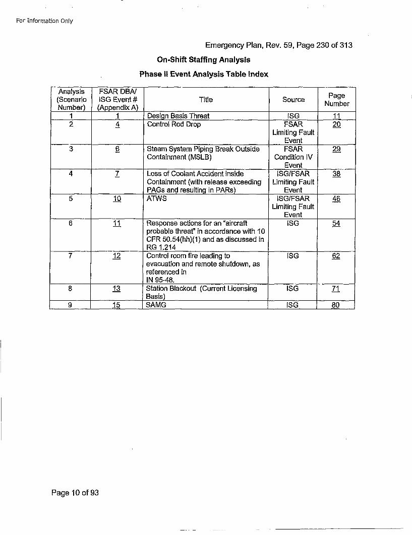
For Information Only
Emergency Plan, Rev. 59, Page 230 of 313On-Shift Staffing Analysis
Phase II Event Analysis Table Index
Analysis ESAR DBN Pg(Scenario ISG Event # Title Source NumberNumber) (Appendix A) Number_____________
1 1 Design Basis Threat ISG 112 4 Control Rod Drop FSAR 2.0
Limiting Fault__________________________ Event
3 6_ Steam System Piping Break Outside FSAR 2_99Containment (MSLB) Condition IV
__________ ________________________ Event4 7 Loss of Coolant Accident inside ISGIFSAR 3_8
Containment (with release exceeding Limiting Fault______PAGs and resulting in PARs) Event
5 100 ATWS ISGIFSAR 4_6-Limiting Fault
Event6 11. Response actions for an "aircraft ISG 54
probable threat" in accordance with 10CFR 50.54(hh)(1) and as discussed inRG 1.214
712 Control room fire leading to ISG 62.evacuation and remote shutdown, asreferenced inIN 95-48.
8 1._3 Station Blackout (Current Licensing ISG 7"1____________ Basis) _______ _____
9 15 SAMG ISG 8_0
Page 10 of 93
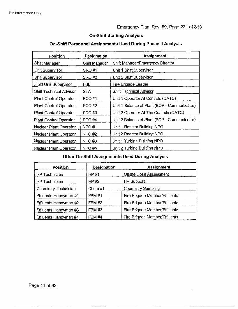
For Information Only
Emergency Plan, Rev. 59, Page 231 of 313
On-Shift Staffing Analysis
On-Shift Personnel Assignments Used During Phase II Analysis
Position Designation Assignment
Shift Manager Shift Manager Shift Manager/Emergency Director
Unit Supervisor SRO #1 Unit 1 Shift Supervisor
Unit Supervisor SRO #2 Unit 2 Shift Supervisor
Field Unit Supervisor FBL Fire Brigade Leader
Shift Technical Advisor STA Shift Technical Advisor
Plant Control Operator PCO #1 Unit I Operator At Controls (OATC)
Plant Control Operator P00 #2 Unit 1 Balance of Plant (BOP - Communicator)
Plant Control Operator PC0 #3 Unit 2 Operator At The Controls (OATC)
Plant Control 0perator P00 #4 Unit 2 Balance of Plant (BOP - Communicator)
Nuclear Plant Operator NPO #1 Unit 1 Reactor Building NPO
Nuclear Plant 0perator NPO #2 Unit 2 Reactor Building NPO
Nuclear Plant Operator NPO #3 Unit 1 Turbine Building NPO
Nuclear Plant 0perator NPO #4 Unit 2 Turbine Building NPO
Other On-Shift Assignments Used During Analysis
Position Designation Assignment
HP Technician HP #1 Offsite Dose Assessment
HP Technician HP #2 HP Support
Chemistry Technician Chem #1 Chemistry Sampling
Effluents Handyman #1 FBM #1 Fire Brigade Member/Effluents
Effluents Handyman #2 FBM #2 Fire Brigade Member/Effluents
Effluents Handyman #3 FBM #3 Fire Brigade Member/Effluents
Effluents Handyman #-4 FBM #4 Fire Brigade Member/Effluents
Page 11 of 93
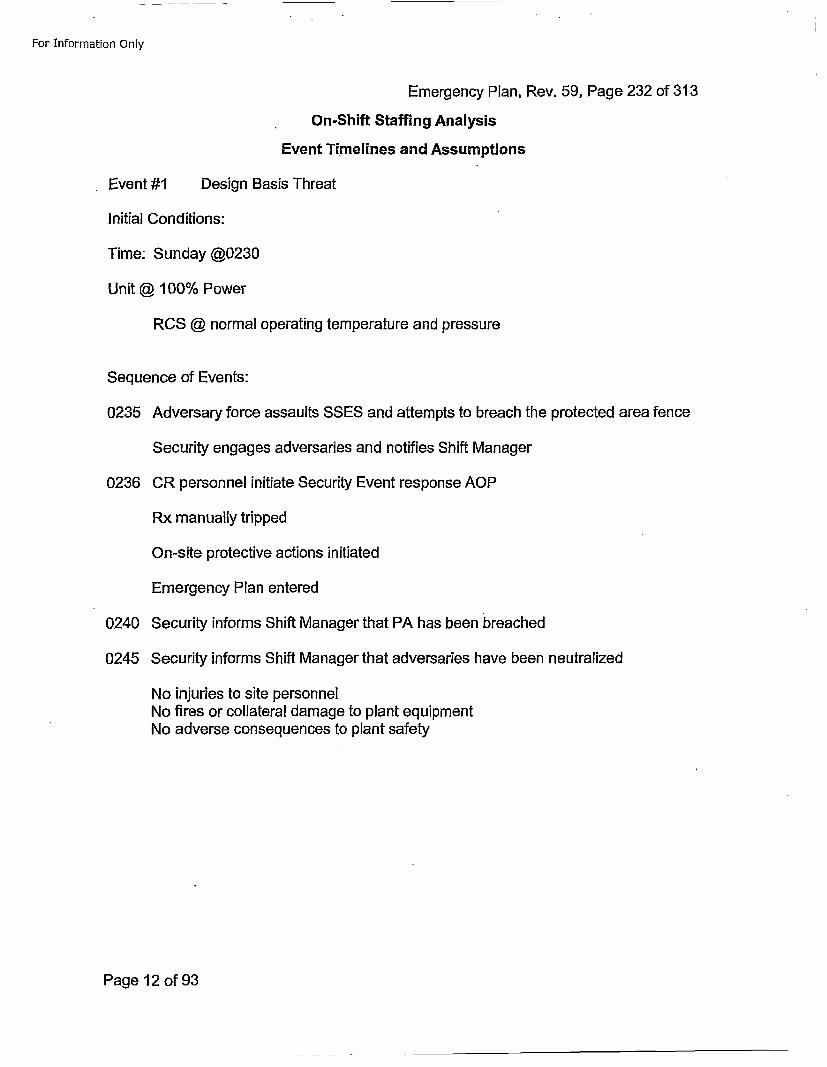
For Information Only
Emergency Plan, Rev. 59, Page 232 of 313On-Shift Staffing Analysis
Event Timelines and Assumptions
Event #1 Design Basis Threat
Initial Conditions:
Time: Sunday @0230
Unit @ 100% Power
RCS @ normal operating temperature and pressure
Sequence of Events:
0235 Adversary force assaults SSES and attempts to breach the protected area fence
Security engages adversaries and notifies Shift Manager
0236 CR personnel initiate Security Event response AOP
Rx manually tripped
On-site protective actions initiated
Emergency Plan entered
0240 Security informs Shift Manager that PA has been breached
0245 Security informs Shift Manager that adversaries have been neutralized
No injuries to site personnelNo fires or collateral damage to plant equipmentNo adverse consequences to plant safety
Page 12 of 93
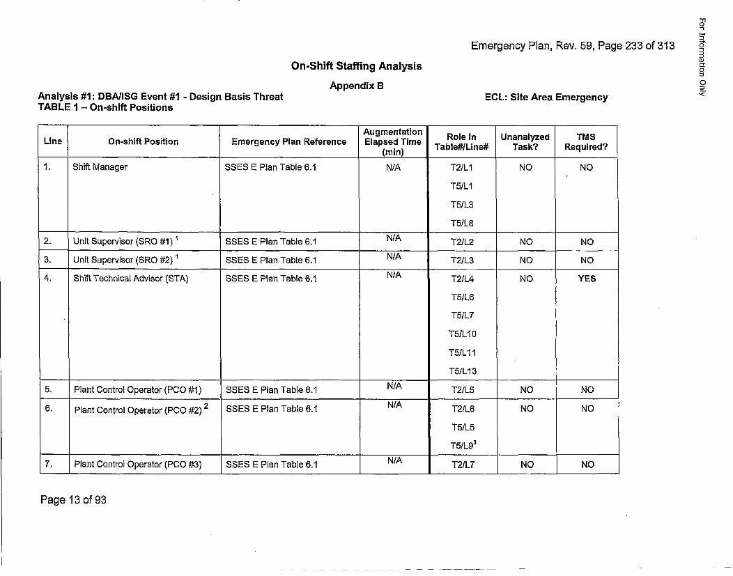
Emergency Plan, Rev. 59, Page.233 of 313
'1
0
0-
On-Shift Staffing AnalysisAppendix B
Analysis #1: DBA/ISG Event #1 - Design Basis ThreatTABLE 1 - On-shift Positions
0
ECL: Site Area Emergency "
Augmentation Role in Unanalyzed TMSLine On-shift Position Emergency Plan Reference Elapsed Time(m) Table#ILine# Task? Required?
1. Shift Manager SSES E Plan Table 6.1 N/A T2/LI NO NO
T5ILI
T51L3
T5/L8
2. Unit Supervisor (SRO #1) SSES E Plan Table 6.1 N/A T2/L2 NO NO
3. Unit Supervisor (SRO #2) 1 SSES E Plan Table 6.1 N/A T2/L3 NO NO
4. Shift Technical Advisor (STA) SSES E Plan Table 6.1 N/A T2/L4 NO YES
T5/L6
T5IL7
T5ILI0
T5ILI 1
T5ILI 3
5. Plant Control Operator (PC0 #1) SSES E Plan Table 6.1 N/A T2/L5 NO NO
6. Plant Control Operator (PCO #2) 2 SSES E Plan Table 6.1 N/A T2/L6 NO NO
T5/L5
T5/L93
7. Plant Control Operator (PCO #3) SSES E Plan Table 6.1 N/A T2/L7 NO NO
Page 13 of 93
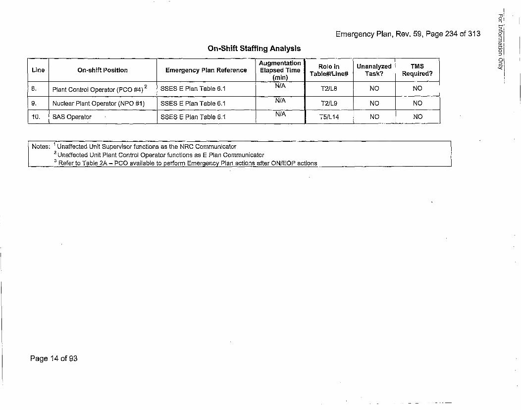
Emergency Plan, Rev. 59, Page 234 of 313On-Shift Staffing Analysis
Augmentation Role in Unanalyzed TMSLine On-shift Position Emergency Plan Reference Elapsed Time
(m) Table#ILine# Task? Required?8. Plnt CntrolOpertor (00 #)2 SS E lan Tble .1(Nain)L N N
9. Nuleart Plantro Operator (NPCO #1)2 SSES E Plan Table 6.1 N/A T2/L8 NO NO
10. SAS Operator SSES E Plan Table 6.1 N/A T5/L14 NO NO
Notes: Unaffected Unit Supervisor functions as the NRC Communicator
2 Unaffected Unit Plant Control Operator functions as E Plan CommunicatorSRefer to Table 2A - P00 available to perform Emergency Plan actions after ONIEOP actions
Page 14 of 93
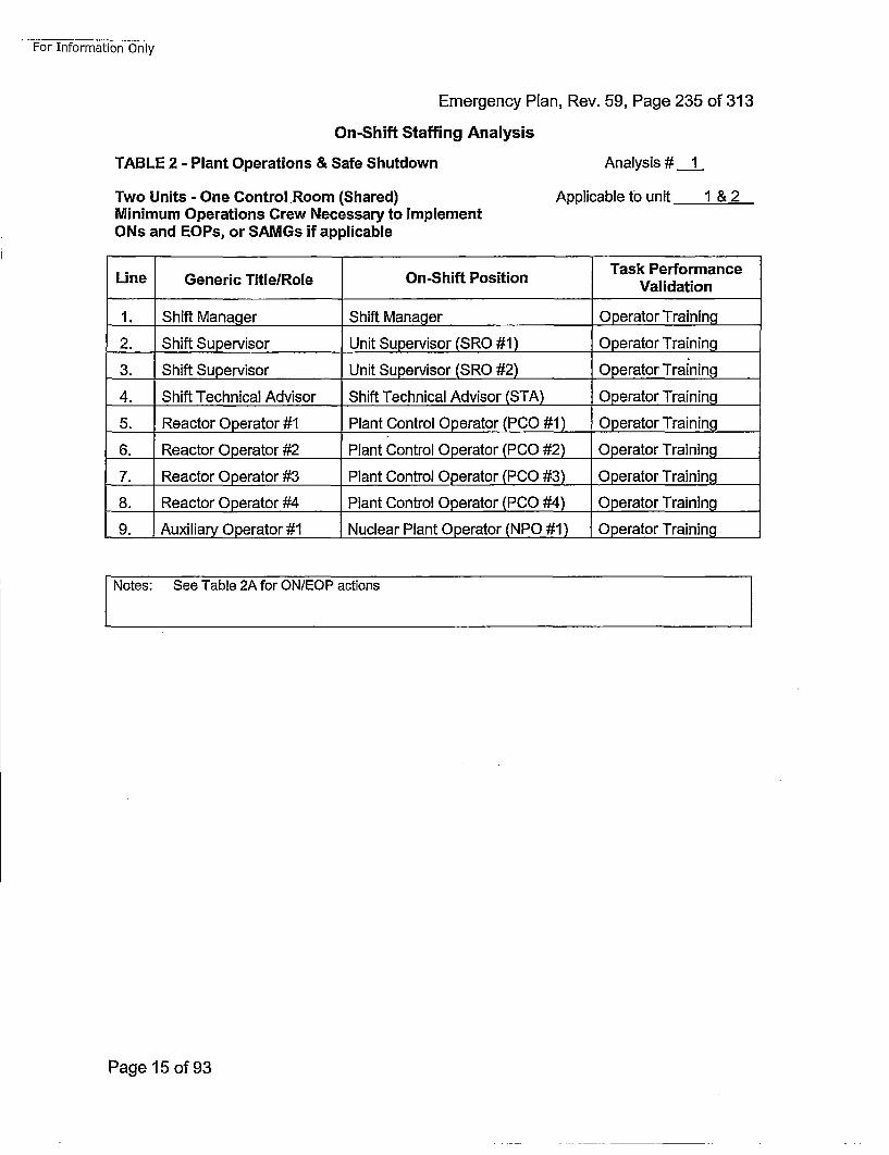
For Information Only
Emergency Plan, Rev. 59, Page 235 of 313
On-Shift Staffing Analysis
TABLE 2 - Plant Operations & Safe Shutdown
Two Units - One Control Room (Shared)Minimum Operations Crew Necessary to ImplementONs and EOPs, or SAMGs if applicable
Analysis #.j
Applicable to unit 1 & 2
Task PerformanceLine Generic Title/Role On-Shift Position Vldto
1. Shift Manager Shift Manager Operator Training
2. Shift Supervisor Unit Supervisor (SRO #1) Operator Training
3. Shift Supervisor Unit Supervisor (SRO #2) Operator Training
4. Shift Technical Advisor Shift Technical Advisor (STA) Operator Training
5. Reactor Operator #1 Plant Control Operator (PC0 #1) Operator Training
6. Reactor Operator #2 Plant Control Operator (PCO #2) Operator Training
7. Reactor Operator #3 Plant Control Operator (PCO #3) Operator Training
8. Reactor Operator #4 Plant Control Operator (PCO #4) Operator Training
9. Auxiliary Operator #1 Nuclear Plant Operator (NPO #1) Operator Training
[ Notes: See Table 2A for ON/EOP actions
Page 15 of 93
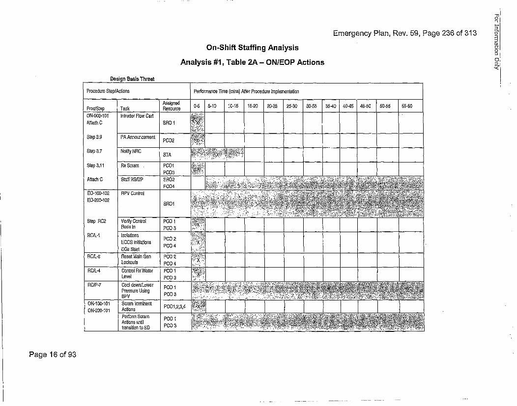
'-I
Emergency Plan, Rev. 59, Page 236 of 313 5'
On-Shift Staffing Analysis 0
Analysis #1, Table 2A - ON/EOP Actions •
-Ti
Page 16 of 93
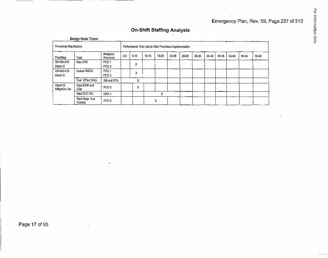
Emergency Plan, Rev. 59, Page 237 of 313
-Il0
0"
0]
0
0
On-Shift Staffing AnalysisDesign Basis Threat
Procedure StepfActions Performance Time (mins) After Procedure Implementation
PrcSeAakRsourced 0-5 5-10 10-15 15-20 20-25 25-30 30-35 35-40 40-45 45-50 50-55 55-50
ON-00O-010 Max CRD PCO 1Attach C PCO 3 ___ ______
ON-COO-Gb10 Isolate RWCU PCO 1Attach C PCO 3X
Eval EPlan Entry SM and STA X
Attach G Start ESW and P0Mitigation List DGs____
Start SCC DS NPO 1 XStart Supp Pool P00 2 X
________Cooling I____________________
Page 17 of 93
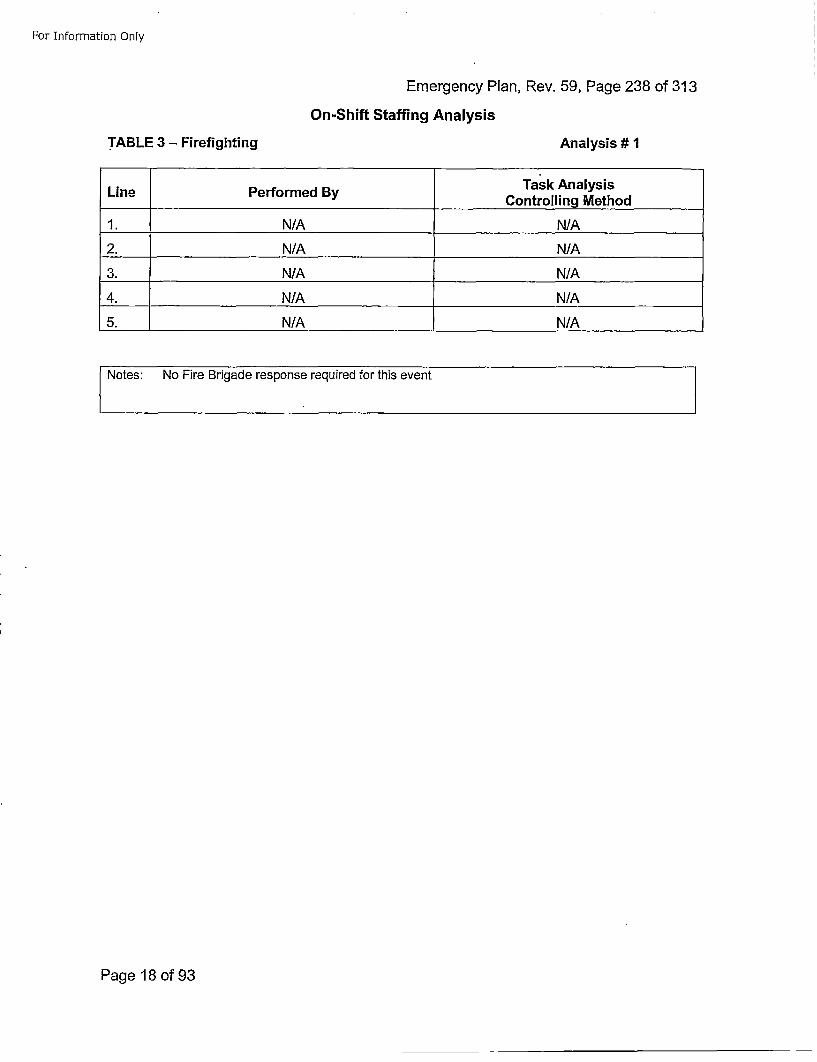
For Information Only
Emergency Plan, Rev. 59, Page 238 of 313On-Shift Staffing Analysis
TABLE 3 - Firefighting Anialysis# 1
LinePerorme ByTask AnalysisLinePerorme ByControlling Method
1. N/A N/A
2. N/A N/A
3. N/A N/A
4. N/A N/A
5. N/A N/A
Notes: No Fire Brigade response required for this event
Page 18 of93
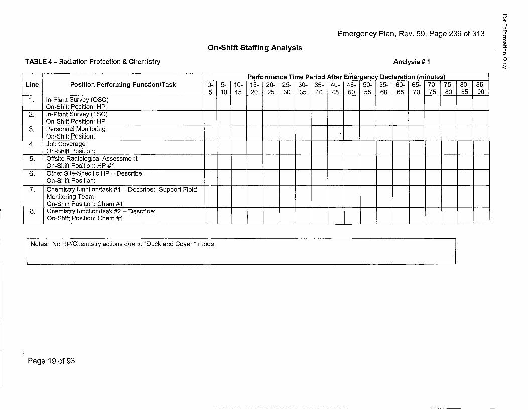
Emergency Plan, Rev. 59, Page 239 of 313
-1o
5n
C
a-0
0<
On-Shift Staffing Analysis
TABLE 4 - Radiation Protection & Chemistry Analysis #
Performance Time Period After Emergency Declaration (minutes)Line Position Performing Function/Task 0- 5- 10- 15- 20- 25- 30- 35- 40- 45- 50- 55- 60- 65- 70- 75- 80- 85-
5 10 15 20 25 30 35 40 45 50 55 60 65 70 75 80 85 901. In-Plant Survey (0SC)
On-Shift Position: HP2. In-Plant Survey (TSC)
On-Shift Position: HP3. Personnel Monitoring
On-Shift Position:4. Job Coverage
On-Shift Position:5. Offsite Radiological Assessment
___On-Shift Position: HP #16. Other Site-Specific HP - Describe:
On-Shift Position:7. Chemistry function/task #1 - Describe: Support Field
Monitoring TeamOn-Shift Position: Chem #1
B. Chemistry function/task #2 - Describe:On-Shift Position: Chem #1
Notes: No HP/Chemistry actions due to "Duck and Cover" mode
Page 19 of 93
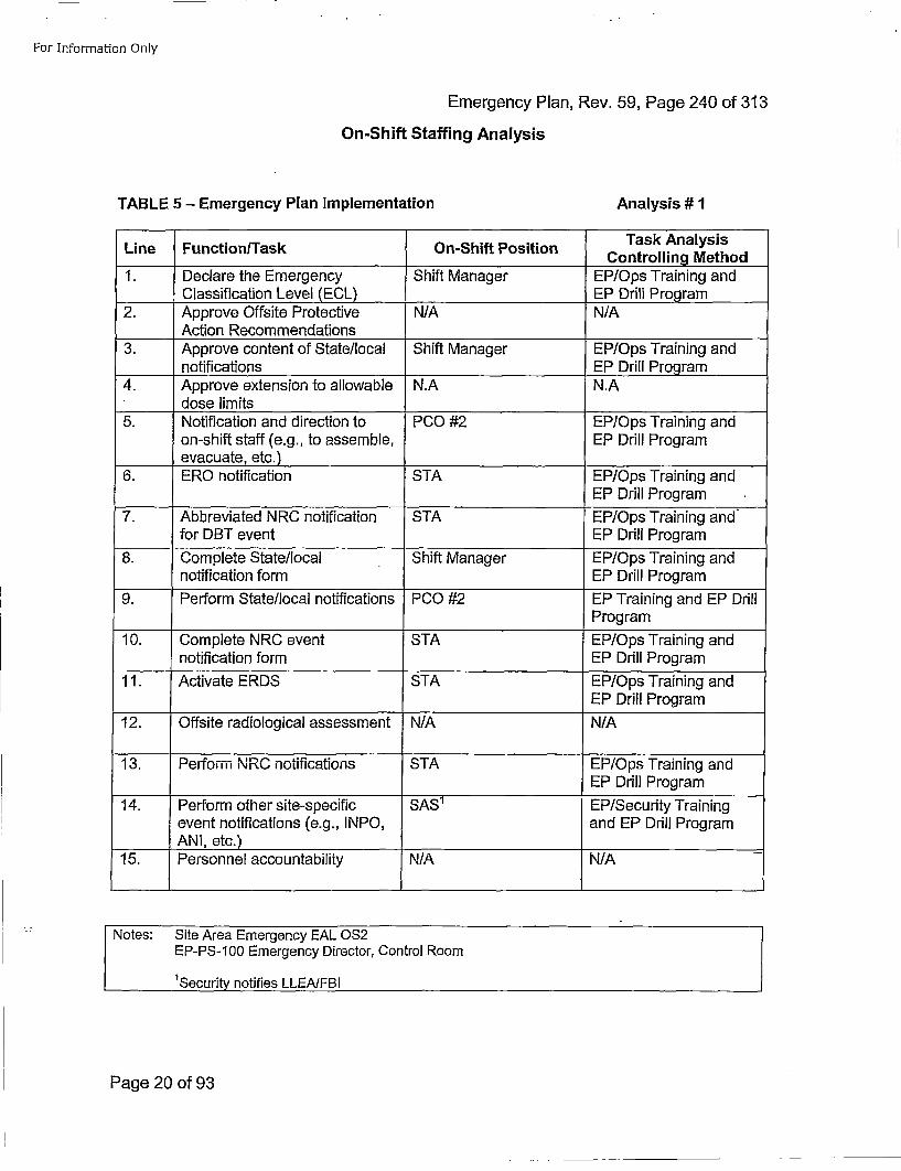
For Information Only
Emergency Plan, Rev. 59, Page 240 of 313On-Shift Staffing Analysis
TABLE 5 - Emergency Plan Implementation Analysis # 1
Line Function/Task On-Shift PositionTakAlyiControlling Method
1. Declare the Emergency Shift Manager EP/Ops Training andClassification Level (ECL) EP Drill Program
2. Approve Offsite Protective N/A N/AAction Recommendations __________
3. Approve content of State/local Shift Manager EP/Ops Training andnotifications_____EP Drill Program
4. Approve extension to allowable N.A N.Adose limits ____________
5. Notification and direction to PCO #2 EP/Ops Training andon-shift staff (e.g., to assemble, EP Drill Programevacuate, etc.)
6. ERO notification STA EP/Ops Training andEP Drill Program
7. Abbreviated NRC notification STA EP/Ops Training andfor DBT event EP Drill Program
8. Complete State/local Shift Manager EP/Ops Training andnotification form EP Drill Program
9. Perform State/local notifications PCO #2 EP Training and EP DrillProgram
10. Complete NRC event STA EP/Ops Training andnotification form EP Drill Program
11. Activate ERDS STA EP/Ops Training andEP Drill Program
12. Offsite radiological assessment N/A N/A
13. Perform N RC notifications STA EP/Ops Training andEP Drill Program
14. Perform other site-specific SAS1 EP/Security Trainingevent notifications (e.g., INPO, and EP Drill Program
____ANI, etc.)15. Personnel accountability N/A N/A-
Notes: Site Area Emergency EAL 0S2
EP-PS-100 Emergency Director, Control Room
'Security notifies LLEAIFBI
Page 20 of 93
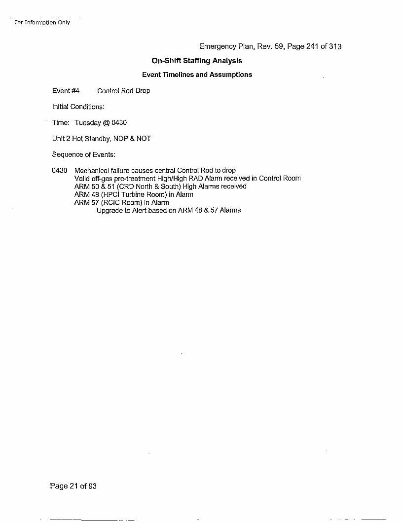
For Information Only
Emergency Plan, Rev. 59, Page 241 of 313
On-Shift Staffing Analysis
Event Timelines and Assumptions
Event #4 Control Rod Drop
Initial Conditions:
Time: Tuesday @0430
Unit 2 Hot Standby, NOP & NOT
Sequence of Events:
0430 Mechanical failure causes central Control Rod to dropValid off-gas pr~e-treatment High/High RAD Alarm received in Control RoomARM 50 & 51 (CR0 North & South) High Alarms receivedARM 48 (HPCI Turbine Room) in AlarmARM 57 (RCIC Room) in Alarm
Upgrade to Alert based on ARM 48 & 57 Alarms
Page 21 of 93
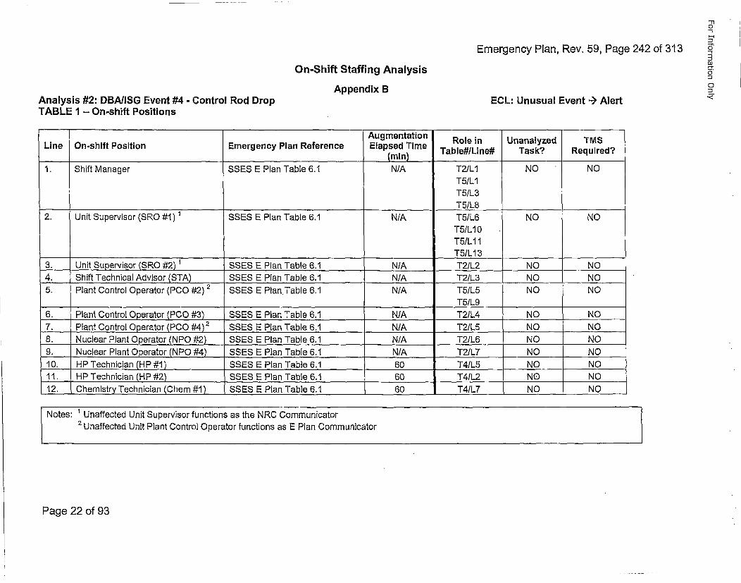
Emergency Plan, Rev. 59, Page 242 of 313
"-rl0
n•
o
-1On-Shift Staffing Analysis
Appendix B o
ECL: Unusual Event --) Alert •Analysis #2: DBA/ISG Event #4 - Control Rod DropTABLE I - On-shift Positions
Augmentation Role in Unanalyzed TMSLine On-shift Position Emergency Plan Reference Elapsed Time TbeIie ak eurd(mn) Tbe/ie ak eurd
1. Shift Manager SSES E Plan Table 6.1 N/A T2/L1 NO NOT5/L1T5/L3
_________________________ ______________________T51L8
2. Unit Supervisor (SRO #1) 1 SSES E Plan Table 6.1 N/A T5/L6 NO NOT5/L 10T5/LI11
_______ _______ _______ ______T51L 13 _ _ _ _ _ _
3. Unit Supervisor (SRO #2) 1 SSES E Plan Table 6.1 N/A T2/L2 NO NO4. Shift Technical Advisor (STA) SSES E Plan Table 6.1 N/A T2/L3 NO NO5. Plant Control Operator (PC0 #2) 2 SSES E Plan. Table 6.1 N/A T51L5 NO NO
T5/L96. Plant Control Operator (PCO #3) SSES E Plan Table 6.1 N/A T2/L4 NO NO7. Plant Control Operator (PCO #4)2 SSES E Plan Table 6,1 N/A T2/L5 NO NO8. Nuclear Plant Operator (NPO #2) SSES E Plan Table 6.1 N/A T21L6 NO NO9. Nuclear Plant Operator (NPO #4) SSES E Plan Table 6.1 N/A T2/L7 NO .. NO10. HP Technician (HP #1) SSES E Plan .Table 6.1 60 T4/L5 NO NO11. HP Technician (HP #2) SSES E Plan Table 6.1 60 T4/L2 NO NO12. Chemistry Technician (Chem #1) SSES E Plan Table 6.1 60 T41L7 NO NO
Notes: 1 Unaffected Unit Supervisor functions as the NRC Communicator2 UnfetdUnit Plant Control Operator functions as E Plan Communicator
Page 22 of 93
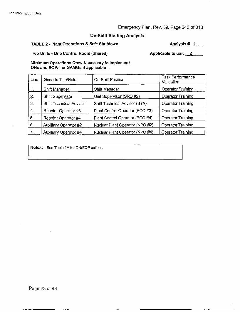
For Information Only
Emergency Plan, Rev. 59, Page 243 of 313
On-Shift Staffing Analysis
TABLE 2 - Plant Operations & Safe Shutdown Analysis # 2
Two Units - One Control Room (Shared)
Minimum Operations Crew Necessary to ImplementONs and EOPs, or SAMGs if applicable,
Applicable to unit 2
Task PerformanceLine Generic Title/Role On-Shift Position Vldto
1. Shift Manager Shift Manager Operator Training
2. Shift Supervisor Unit Supervisor (SRO #2) Operator Training
3. Shift Technical Advisor Shift Technical Advisor (STA) Operator Training
4. Reactor Operator #3 Plant Control Operator (PCO #3) Operator Training
5. Reactor Operator #4 Plant Control Operator (PCO #4) Operator Training
6. Auxiliary Operator #2 Nuclear Plant Operator (NPO #2) Operator Training
7. Auxiliary Operator #4 Nuclear Plant Operator (NPO #4) Operator Training
Notes: See Table 2A for ON/EOP actions
Page 23 of 93
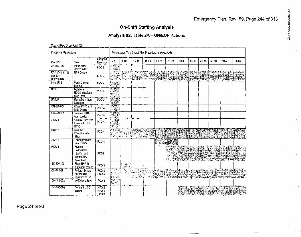
-rn0
Emergency Plan, Rev. 59, Page 244 of 313 s
On-Shift Staffing Analysis •
Analysis #2, Table 2A - ON/EOP Actions=
Page 24 of 93
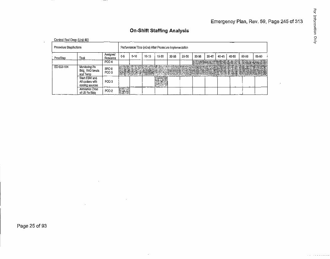
'-'n
Emergency Plan, Rev. 59, Page 245 of 313 =•5
-'-.On-Shift Staffing Analysis
Control Rod Drop Unit #2)
Procedure Step/Actions Performance Time (mains) After Procedure Implementation
Proc/Step Task Resource 0-5 5-10 10-15 15-20 20-25 25-30 [30-35 [35-40 40-45 45-50 50-55 55-50
Bldg PAD levels *4
Start ESW end !
cooling sources .,__.-._-__.__ -. _____-,., ____ ___ ____
________________ of U2 Rx Bldg ___ .:_____ .: _____________,_____ ___ ____ ________
0
Page 25 of 93
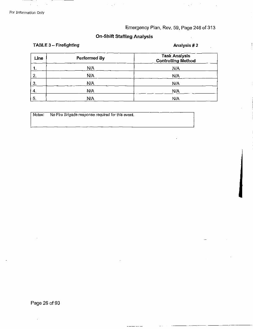
For Information Only
Emergency Plan, Rev. 59, Page 246 of 313On-Shift Staffing Analysis
TABLE 3 - Firefighting Analysis # 2
LinePerorme ByTask AnalysisLieerored_ Controlling Method
1. N/A N/A
2. N/A N/A
3. N/A N/A
4. N/A N/A
5. N/A N/A
Notes: No Fire Brigade response required for this event.
Page 26 of 93
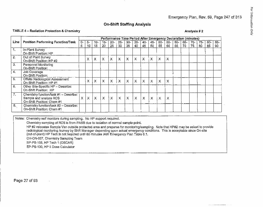
Emergency Plan, Rev. 59, Page 247 of 313
"F10
0-
0"
0JOn-Shift Staffing Analysis
TABLE 4 - Radiation Protection & Chemistry Analysis #2
Performance Time Period After Emergency Declaration (inutes)-Line Position Performing Function/Task 0- 5- 10- 15- 20- 25- 30- 35- 40- 45- 50- 55- 60- 65- 70- 75- 80- 85-
5 10 15 20 25 30 35 40 45 50 55 60 65 70 75 80 85 901. In-Plant Survey
On-Shift Position: HP2. Out of Plant SurveyX X X X X X X X X X X
On-Shift Position: HP #2X X X X X X X X X X X3. Personnel Monitoring
___On-Shift Position:4. Job Coverage
On-Shift Position:5. Offsite Radiological Assessment ~ ~ >
On-Shift Position: HP #1X X X X X X X X X X X6. Other Site-Specific HP - Describe:
On-Shift Position: HP7. Chemistry function/task #1 - Describe:
Sample and analyze RCS X X X X X X X X X X X XOn-Shift Position: Chem #1
8. Chemistry function/task #2 - Describe:On-Shift Position: Chem #1
Notes: Chemistry self monitors during sampling. No HP support required.Chemistry sampling of RCS is from PASS due to isolation of normal sample point.HP #2 relocates Sample Van outside protected area and prepares for monitoring/sampling. Note that HP#2 may be asked to provideradiological monitoring /survey by Shift Manager depending upon actual emergency conditions. This is acceptable since On-site(out-of-plant) HP Tech is not required until 60 minutes lAW Emergency Plan Table 6.1.CH-ON-007, Chemistry Sampling TeamEP-PS-1 08, HP Tech I (OSCAR)EP-PS-1 30, HP II Dose Calculator
Page 27 of 93
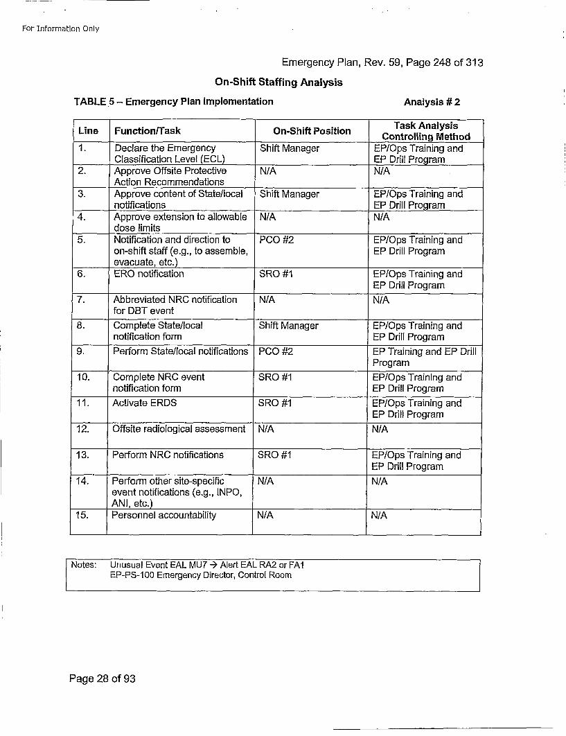
For Information Only
Emergency Plan, Rev. 59, Page 248 of 313On-Shift Staffing Analysis
TABLE 5- Emergency Plan Implementation Analysis # 2
Task AnalysisLine Function/Task On-Shift Position CnrligMto
1. Declare the Emergency Shift Manager EP/Ops Training and____Classification Level (ECL) EP Drill Program
2. Approve Offsite Protective N/A N/AAction Recommendations
3. Approve content of State/local Shift Manager EP/Ops Training andnotifications EP Drill Program
4. Approve extension to allowable N/A N/Adose limits
5. Notification and direction to PCO #2 EP/Ops Training andon-shift staff (e.g., to assemble, EP Drill Programevacuate, etc.) ___________
6. ERO notification SO# POsTann n
7. Abbreviated NRC notification N/ANAfor DBT event
8. Complete State/local Shift Manager EP/Ops Training andnotification form EP Drill Program
9. Perform State/local notifications PCO #2 EP Training and EP DrillProgram
10. Complete NRC event SRO #1 EP/Ops Training andnotification form EP Drill Program
11. Activate ERDS SRO #1 EP/Ops Training andEP Drill Program
12. Offsite radiological assessment N/A N/A
13. Perform NRC notifications SRO #1 EP/Ops Training andEP Drill Program
14. Perform other site-specific N/A N/Aevent notifications (e.g., INPO,ANI, etc.)
15. Personnel accountability N/A N/A
Notes: Unusual Event EAL MU7 --) Alert EAL RA2 or FAlEP-PS-100 Emergency Director, Control Room
Page 28 of 93
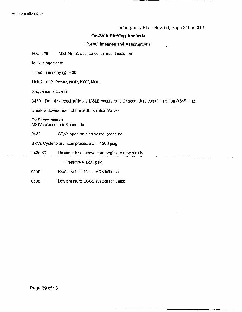
For Information Only
Emergency Plan, Rev. 59, Page 249 of 313
On-Shift Staffing Analysis
Event Timelines and Assumptions
Event #6 MSL Break outside containment isolation
initial Conditions:
Time: Tuesday @ 0430
Unit 2 100% Power, NOP, NOT, NOL
Sequence of Events:
0430 Double-ended guillotine MSLB occurs outside secondary containment on A MS Line
Break is downstream of the MSL Isolation Valves
Rx Scram occursMSIVs closed in 5.5 seconds
0432 SRVs open on high vessel pressure
SRVs Cycle to maintain pressure at =1200 psig
0435:30 Rx water level above core begins to drop slowly
Pressure =1200 psig
0505 RxV Level at -161" - ADS initiated
0508 Low pressure ECCS systems initiated
Page 29 of 93
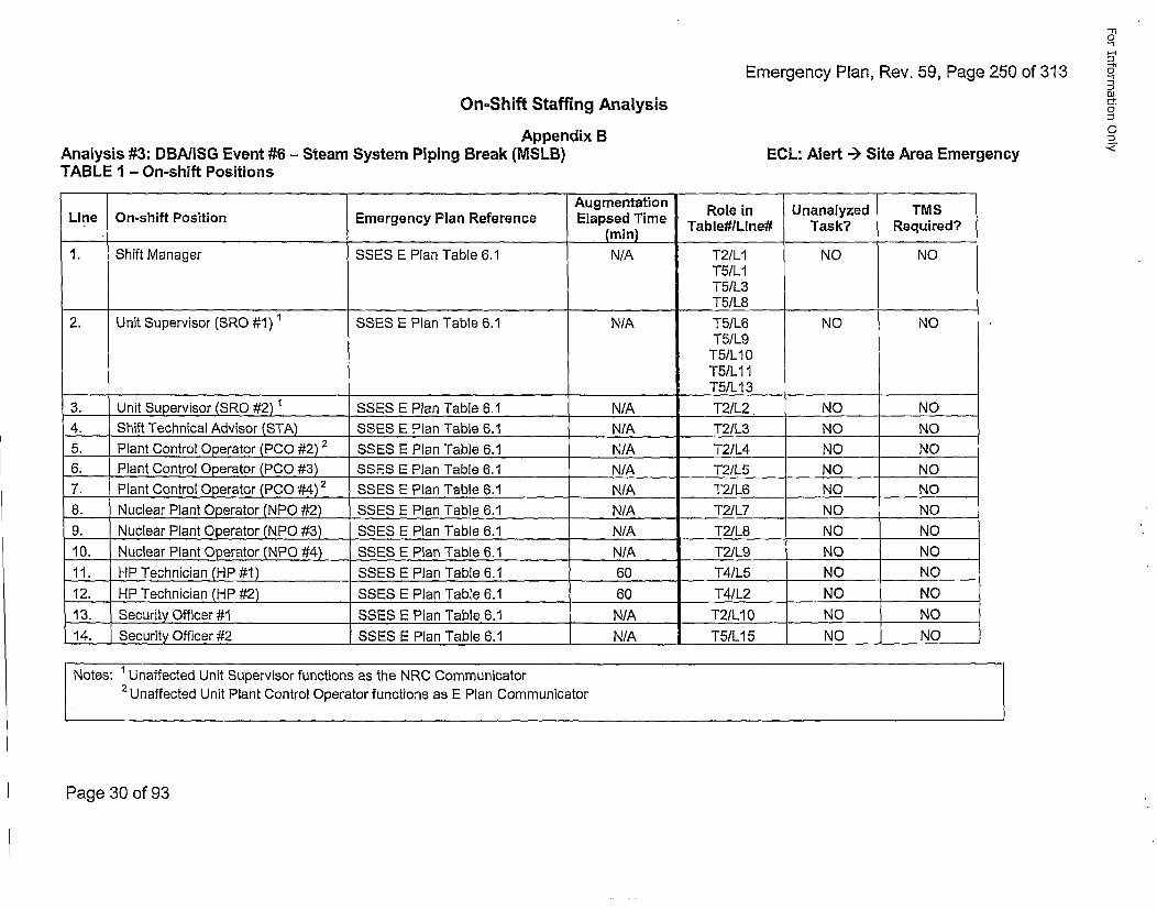
Emergency Plan, Rev. 59, Page 250 of 313
"1"1C
-I
O~
0
DJOn-Shift Staffing Analysis
Appendix BAnalysis #3: DBA/ISG Event #6 - Steam System Piping Break (MSLB)TABLE I - On-shift Positions ECL: Alert -- Site Area Emergency
Lie n-hit oitonEmrgnc la Rfeene Augmentation Role in Unanalyzed TMSLineOn-hiftPostio Emegeny Pan Rfernce Elapsed Time
(mmn) Table#/Line# Task? Required?
1. Shift Manager SSES E Plan Table 6.1 N/A T2/L1 NO NOT5/LIT5/L3
____ ____ ___ ____ ____ ___T5/L8
2. Unit Supervisor (SRO #1) 1 SSES E Plan Table 6.1 N/A T5/L6 NO NOT51L9T5/L10T5/LIIT5/LI 3 ______
,3. Unit Supervisor (SRO #2) 1 SSES E Plan Table 6.1 N/A T2/L2 NO NO4. Shift Technical Advisor (STA) SSES E Plan Table 6.1 N/A_____ T21L3 NO NO5. Plant Control Operator (PCO #2) 2 SSES E Plan Table 6.1 N/A____ T21L4 NO NO6. Plant Control Operator (PCO.#3) SSES E Plan Table 6.1 N/A____ T2/L5 NO NO7'. Plant Control Operator (PCO #4)2 SSES E Plan Table 6.1 NAT2/L6 NO NO8. Nuclear Plant Operator (NPO #2) SSES E Plan Table 6.1 N/A____ T2/L7 NO NO9. Nuclear Plant Operator (N.PO #3) SSES .E.Pl.an Table 6.1 N/A____ T2/L8 NO NO10. Nuclear Plant Operator (NPO #•4) SSES E Plan Table 6.1 N/A T2JL9 NO NO11. HP Technician (HP #1) SSES E Plan Table 6.1 60 T4/L5 .. NO NO12. HP Technician (HP #2) SSES E Plan Table 6.1 60 T4/L2 NO NO13. Security Officer #1 SSES E Plan Table 6.1 N/A T2/L10 NO NO14. Security Officer #2 SSES E Plan Table 6.1 N/A T5/L15 NO NO
Notes: Unaffected Unit Supervisor functions as the NRC Communicator2 Unaffected Unit Plant Control Operator functions as E Plan Communicator
Page 30 of 93
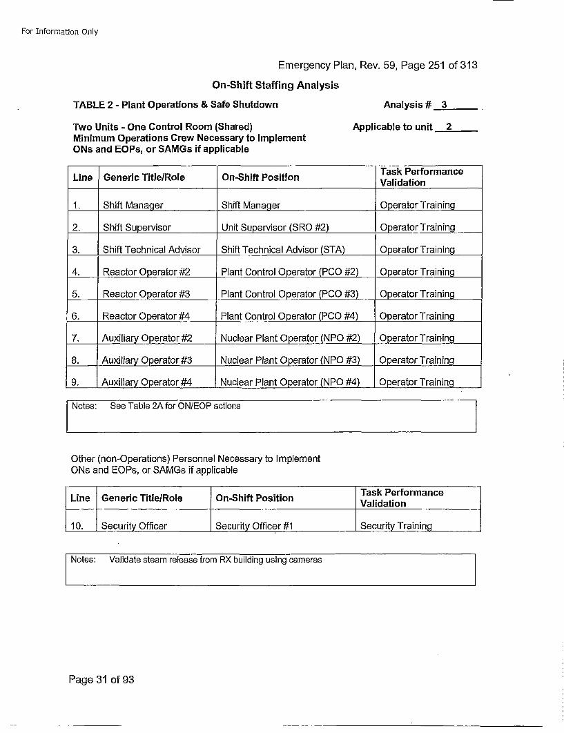
For Information Only
Emergency Plan, Rev. 59, Page 251 of 313On-Shift Staffing Analysis
TABLE 2 - Plant Operations & Safe Shutdown Analysis # 3
Two Units - One Control Room (Shared) Applicable to unit 2Minimum Operations Crew Necessary to ImplementONs and EOPs, or SAMGs if applicable
Task PerformanceLine Generic Title/Role On-Shift Position Vldto
1. Shift Manager Shift Manager Operator Training
2. Shift Supervisor Unit Supervisor (SRO #2) Operator Training
3. Shift Technical Advisor Shift Technical Advisor (STA) 0perator Training
4. Reactor Operator #2 Plant Control Operator (PCO #2) Operator Training
5. Reactor Operator #3 Plant Control Operator (PCO #3) Operator Training
6. Reactor Operator #4 Plant Control 0perator (PCO #4) Operator Training
7. Auxiliary Operator #2 Nuclear Plant Operator (NPO #2) Operator Training
8. Auxiliary Operator #3 Nuclear Plant Operator (NPO #3) Operator Training
9. Auxiliary Operator #4 Nuclear Plant Operator (NPO #4) Operator Training
Other (non-Operations) Personnel Necessary to ImplementONs and EOPs, or SAMGs if applicable
Task PerformanceLine Generic Title/Role On-Shift Position Vldto
10. Security Officer Security Officer #1 Security Training
Notes: Validate steam release from RX building using cameras
Page 31 of 93
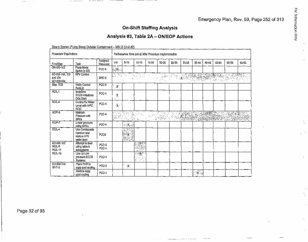
Emergency Plan, Rev. 59, Page 252 of 313
-rl0
0
C
On-Shift Staffing AnalysisAnalysis #3, Table 2A - ON/EOP Actions
Steam System Piping Break Outside Containment - MSLB (Unit #2)
Procedure Step/Actions Perfornance Time (mins) After Procedure Implementation
Assigned 0-5 5-10 10-15 15-20 20-25 25-30 30-35 35-40 40-45 45-50 50-55 55-60•Proc/Step Task Resource__ _ __ _ __ _ __ _
0N-200-102 Place Mode PC .. Ii:ii.Switchin SlD P0.3
E0-200-102, 103 RPV Control ,.:.¢;; . . ..... . .. ,,, .... . , 7.....G0.-200-004 ____ ___ ___ ___ _:__'___:_' ' __:_.. .._ .'_Step FIC2 Verily Control PCO 3
Rods In X _ _ _ _ _ _ ___ ____'______
ROIL-1 IsolationsECCS lnitiations PCO04 .XDGs Start ._ _ ___ ___ ___ ___
RC/L-4 Control Rx WaterLevel with HPIC PC4 ...
Pressurewith.P00 ..:>.. . .. , . ... ..... . . •,: , .• .~. ,.... •' .'.:•:••'..
Pressure with PC04 ' -. . . . . . . . . . .. . . . . . . .. . . . -. .- .. ,. -.. ,;,..., . .. : ,, ... ,__ _ _ _ _ _ _ SRVs '' " ' ": ." ./ -' . "' ''"''"' ': ":"; ' '••' • :"'' '- •;" $ ' :''''"'" '; ': ,E.,;.' S ..
R(•lP-7 Lower pressure P0"04' .u s in g S R V s P O 4: .! y . .j
RC/L-4 Use Condensate -i••i :-:i:injection and PCoa."03:X "i:restore RPV :;!.•.•water level ,,:'. ,-.:
E0-200-102 Attempt to feed PC.O 3 X.-:;,
RC/I.-t 1 subsystems PCO___ ____4_______ ___
RCIL-1O Line up Low '-*.,X¢pressure ECOS PCO 4 •...:Systems "_____ ___ ___ _____ _______.' _____ ____
E0-200-103 Place RHR inSPIT'-2 eupp pool cooling PCO 2 • X
Restore supp PCO 4 • ,X;pool cooling •____ ______________. ___ ___
Page 32 of 93
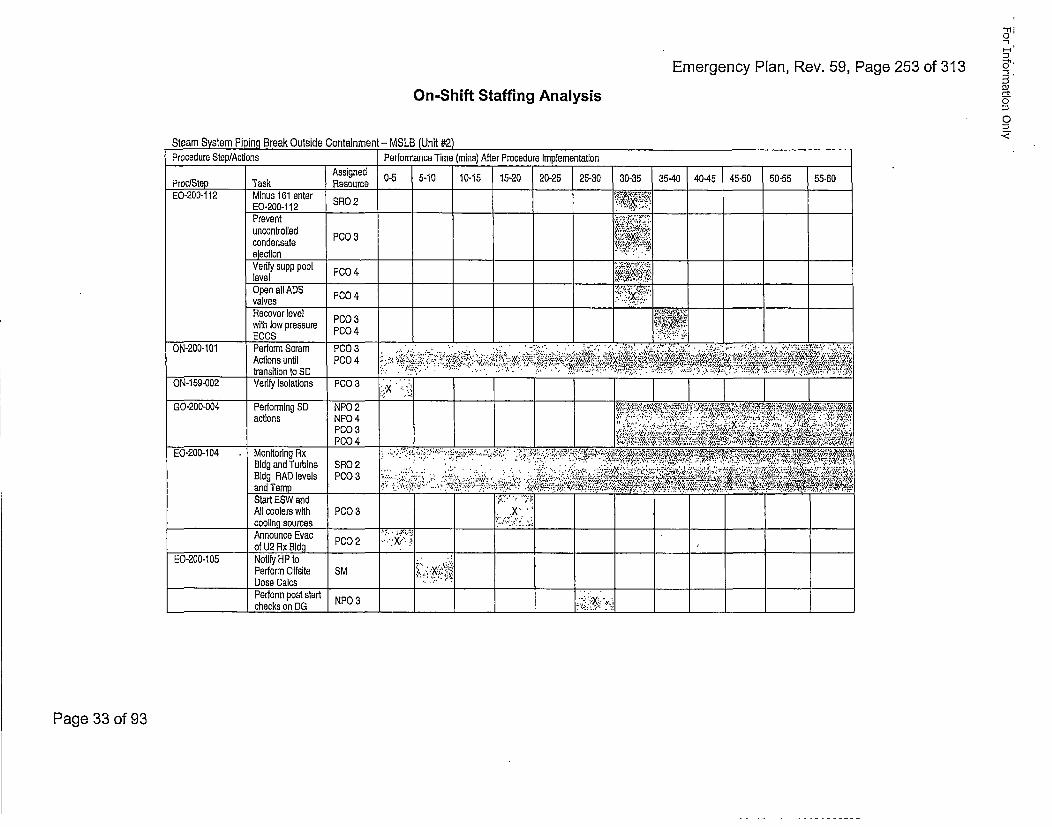
Emergency Plan, Rev. 59, Page 253 of 313
OJ
0
-<
On-Shift Staffing Analysis
Stem Sste PiingBreak Outside Containment - MSLB (Unit #2)Procedure Step/Actions Performance Time (mine) After Procedure Implementation
Assigned 0-5 5-10 10-15 15-20 20-25 25-30 30-35 ,35-40 40-45 45-50 50-55 55-60Proc/Step Task ResourceEO-200-112 Minus 161 enter SRO
E O -2 0 0 -1 1 2S O 2 " . .L . -Prevent "-•'"o:'
condensateeeto P003:" "
Verify supp pool P:004.•:-::level ___ ___Open all ADS P004•!:'valves PCO__...__.__...
Reoe ee ,:with low pressure P004 ,ECCS PCO___4__.___.___ _____ .- __
0N-200-101 Perform Scram P003 •~ ' -* .•- • .." ' '". '.' ::- " • •"" '•""':';' . .":• °:;•"• •••• "' •.Actions until PCO04 ..". , ' -. . . . ...'•••:•:• •-v•-;; .••. .!;.`i: ::..:. .,.,÷ '`x• .• i.. i~••` .•.'>,
_ _ _ _ _ transitiontoS D:O..... . . ' • "__ _ _ . .. '" " < *.:,.:: *.,',"-.• ..'.-:"..'..'.. ...... :,,.:,':-:.,.•::.ON-1 59-002 Verify Isolations P0O03 ___'X_",__""_
GO-200-004 Performing SD NPO 2 t ."'!z • , ";'•••, '.•~~i; A••,,F
actions NPO 4 ,;'£ ••: '!::'::: ' .•2•;•'%"';" :••"-.4** •:;•{••s:*'*;
Bldg RAnd Turbiel PC 3 , . ., - . ,.:.-.,', , •- SR,0 2' .~. -.,.. ,,j, ,, b...:•••` `:•: `•, * `•.• : .•` `•••`:
and Temp .,.,..,.4;;• ...•.:;/• :-I...•,: ... ,. ,, "`.•?`•! :;•;• •`•/:44 #;A••`` ?• :`•• '`• •Start ESW and •",-"All coolers with P00 3 .X'cooling sources .. :;--•
Announce Evac P002 '-•'•:of U2 Rx Bldg PC 2 -':X,.!
EO-200-105 Notify HP to • .i-._•Perform Otfsite SM •,..^.,.•,
______________DoseCalcs ____
Perform post start NPO 3 .:•.X.'.checks onOG ,._____ ___.___-__,____
Page 33 of 93
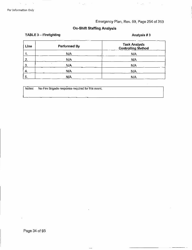
For Information Only
Emergency Plan, Rev. 59, Page 254 of 313On-Shift Staffing Analysts
TABLE 3 - Firefightinig Analysis # 3
LiePerformed By Task AnalysisLine Controlling Method
1. N/A N/A
2. N/A N/A
3. N/A N/A
4. N/A N/A
5. N/A N/A
SNotes: No Fire Brigade response required for this event.
Page 34 of 93
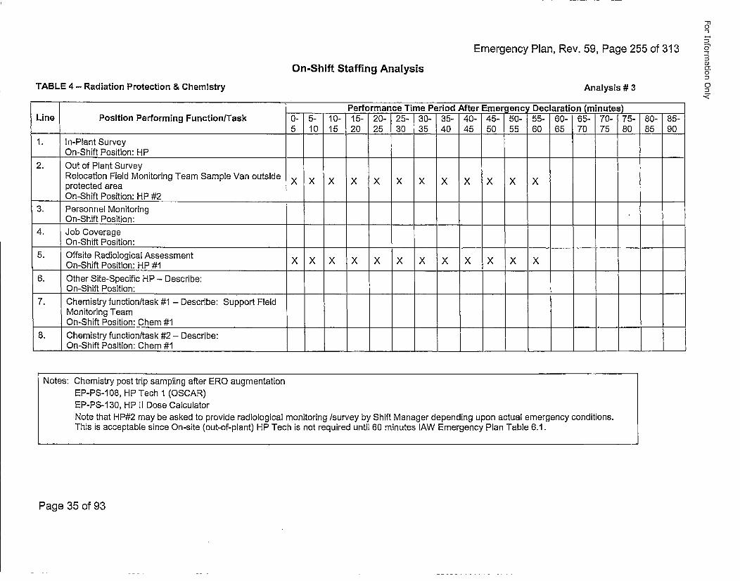
Emergency Plan, Rev. 59, Page 255 of 313
"-I,
0"
O1
0
Di
On-Shift Staffing Analysis
TABLE 4 - Radiation Protection & Chemistry Analysis # 3
Performance Time Period After Emergency Declaratiorn (inutes) __
Line Position Performing Function/Task 0- 5- 10- 15- 20- 25- 30- 35- 40- 45- 50- 55- 60- 65- 70- 75- 80- 85-5 10 15 20 25 30 35 40 45 50 55 60 65 70 75 80 85 90
I. In-Plant SurveyOn-Shift Position: HP
2. Out of Plant SurveyRelocation Field Monitoring Team Sample Van outside x x x x x x x x x xprotected areaOn-Shift Position: HP #2
3. Personnel MonitoringOn-Shift Position:
4. Job CoverageOn-Shift Position:
5. Offsite Radiological Assessment x x x x x x x x x xOn-Shift Position: HP #1 X X X X X X X X X X X
6. Other Site-Specific HP - Describe:On-Shift Position:
7. Chemistry function/task #1 - Describe: support FieldMonitoring Team
___On-Shift Position: Chem #18. Chemistry function/task #2 - Describe:
___On-Shift Position: Chem #1
Notes: Chemistry post trip sampling after ERO augmentationEP-PS-1 08, HP Tech I (OSCAR)EP-PS-1 30, HP II Dose CalculatorNote that HP#2 may be asked to provide radiological monitoring /survey by Shift Manager depending upon actual emergency conditions.This is acceptable since On-site (out-of-plant) HP Tech is not required until 60 minutes lAW Emergency Plan Table 6.1.
Page 35 of 93
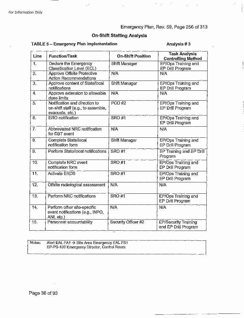
For Information Only
Emergency Plan, Rev. 59, Page 256 of 313
On-Shift Staffing Analysis
TABLE 5 - Emergency Plan Implementation Analysis# 3
Task AnalysisLine Function/Task On-Shift Position CnrligMto
1. Declare the Emergency Shift Manager EP/Ops Training andClassification Level (ECL) EP Drill Program
2. Approve Offsite Protective N/A N/AAction Recommendations
3. Approve content of State/local Shift Manager EP/Ops Training andnotifications EP Drill Program
4. Approve extension to allowable N/A N/Adose limits
5. Notification and direction to PCO #2 EP/Ops Training andon-shift staff (e.g., to assemble, EP Drill Programevacuate, etc.)
6. ERO notification SRO #1 EP/Ops Training andEP Drill Program
7. Abbreviated NRC notification N/A N/Afor DBT event
8. Complete State/local Shift Manager EP/Ops Training andnotification form EP Drill Program
9. Perform State/local notifications SRO #1 EP Training and EP DrillProgram
10. Complete NRC event SRO #1 EP/Ops Training andnotification form EP Drill Program
11. Activate ERDS SRO #1 EP/Ops Training andEP Drill Program
12. Offsite radiological assessment N/A N/A
13. Perform NRC notifications SRO #1 EP/Ops Training andEP Drill Program
14. Perform other site-specific N/A N/Aevent notifications (e.g., INPO,ANI, etc.)
15. Personnel accountability Security Officer #2 EP/Security Trainingand EP Drill Program
Notes: Alert EAL FAI -÷ Site Area Emergency EAL FS1EP-PS-100 Emergency Director, Control Room
Page 36 of 93
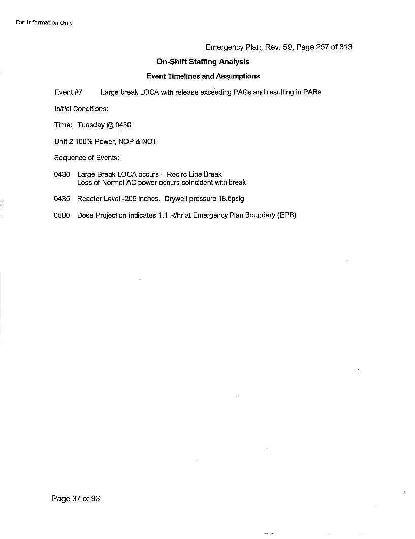
For Information Only
Emergency Plan, Rev. 59, Page 257 of 313On-Shift Staffing Analysis
Event Timelines and Assumptions
Event #7 Large break LOCA with release exceeding PAGs and resulting in PARs
Initial Conditions:
Time: Tuesday @ 0430
Unit 2 100% Power, NOP & NOT
Sequence of Events:
0430 Large Break LOCA occurs - Recirc Line BreakLoss of Normal AC power occurs coincident with break
0435 Reactor Level -205 inches. Drywell pressure 18.5psig
0500 Dose Projection indicates 1.1 R~hr at Emergency Plan Boundary (EPB)
Page 37 of 93
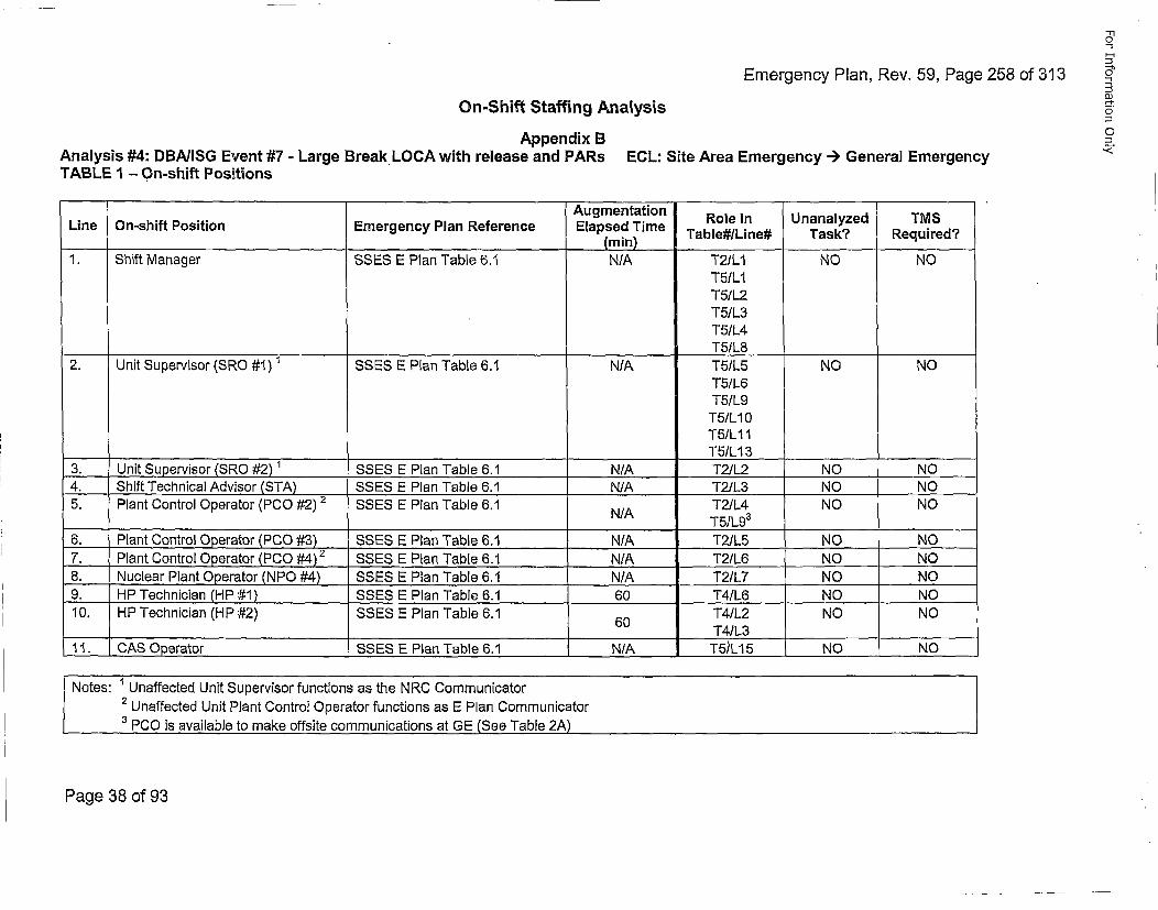
Emergency Plan, Rev. 59, Page 258 of 313On-Shift Staffing Analysis
Appendix BAnalysis #4: DBAIISG Event #7 - Large Break LOCA with release and PARs ECL: Site Area Emergency --) General EmergencyTABLE 1 - On-shift Positions
Ln O-sif ostin mrgnc Pa Rfeene Augmentation Role in Unanalyzed TMSLieO-sitPsiinEmrec Pa efrne Elapsed Time TbeIie ak eurd
(min) _______ _____ _
1. Shift Manager SSES E Plan Table 6.1 N/A T2/L1 NO NO
T5/L2T5/L2T5/L3T5/L4
2. Unit Supervisor (SRO #1) 1 SSES E Plan Table 6.1 N/A T5/L5 NO NOT5/L6T5/L9T5/LI0T5ILI1
______ _____ T51L13_ _ _ _ _ _
3. Unit Supervisor (SRO #2) 1 SSES E Plan Table 6.1 N/A T2/L2 NO NO4. Shift Technical Advi~sor (STA) SSES E Plan Table 6.1 N/A T2/L3 NO NO5. Plant Control Operator (PCO #2) 2 SSES E Plan Table 6.1 T2/L4 NO NO
N/A T5/L9 3
6. Plant Control Operator (PCO #3) SSES E Plan Table 6.1 N/A T21L5 NO "NO7. Plant Control 0perator (P00 #4)2. SSES E Plan Table 6.1 N/A T2/L6 NO NO8. Nuclear Plant Operator (NPO #.4) SSES E Plan Table 6.1 N/A T2/L7 NO NO9. HP Technician (HP #1) SSES E Plan Table 6.1 60 T4/L6 NO NO10. HP Technician (HP #2) SSES E Plan Table 6.1 60T4/L2 NO NO
60 T4/L311. CAS Operator SSES E Plan Table 6.1 N/A T5i•L15 NO NO
Notes: Unaffected Unit Supervisor functions as the NRC CommunicatorSUnaffected Unit Plant Control Operator functions as E Plan Communicator
3 PCO is available to make offsite communications at GE (See Table 2A)
-I"1a
0i
5"
0
Page 38 of 93
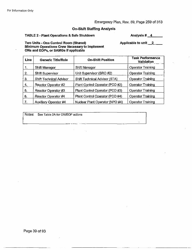
For Information Only
Emergency Plan, Rev. 59, Page 259 of 313On-Shift Staffing Analysis
TABLE 2 - Plant Operations & Safe Shutdown Analysis # 4
Two Units.- One Control Room (Shared)Minimum Operations Crew Necessary to ImplementONs and EOPs, or SAMGs if applicable
Applicable to unit 2
Task PerformanceLine Generic TitleIRole On-Shift Position Vldto
1. Shift Manager Shift Manager Operator Training
2. Shift Supervisor Unit Supervisor (SRO #2) Operator Training
3. Shift Technical Advisor Shift Technical Advisor (STA) Operator Training
4. Reactor Operator #2 Plant Control Operator (PCO #2) Operator Training
5. Reactor Operator #3 Plant Control Operator (PCO #3) Operator Training
6. Reactor Operator #4 Plant Control Operator (PC0 #4) Operator Training
7. Auxiliary Operator #4 Nuclear Plant Operator (NPO #4) Operator Training
Notes: See Table 2A for ON/EOP actions
Page 39 of 93
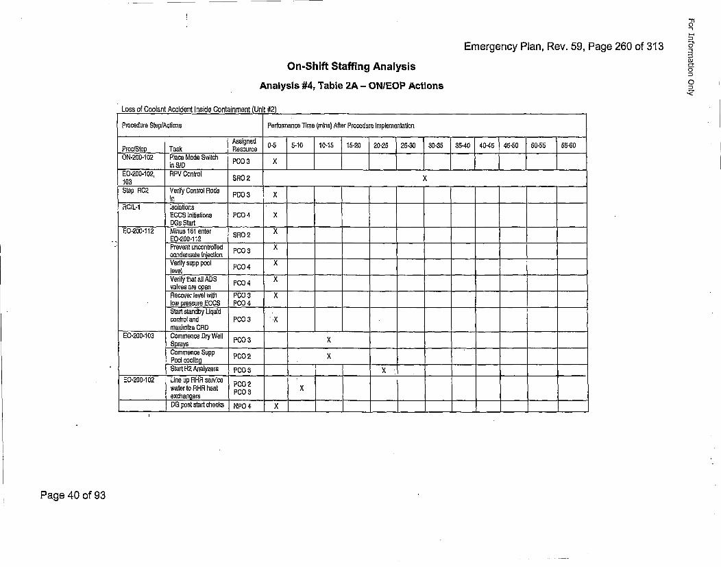
Emergency Plan, Rev. 59, Page 260 of 313
'--I
oJ
0On-Shift Staffing Analysis
Analysis #4, Table 2A - ON/EOP Actions
Loss of Coolant Accident Inside Containment(Ui#2
Procedure Step/Actions Performance Time (mnins) After Procedure Implementation
Assignedl 0-5 5-10 10-15 15-20 20-25 25-30 30-35 35-40 40-45 465,0 50-55 55-60Proc/Step Task Resource _ _ _ _ _ _ _
ON-200-102 Place Mode Switch_ _in SID __ __ __ __O ___ ____ _ _ ____ _ _ _
E0-200-1 02, RPV Control SR2X103 _RO_2 X
Step RC2 Verify Control Rods P0________In ___O___X
ROIL-i IsolationsE0CS Initiations P00 4 XOGs Start ___ ______ ___
E0-200-112 Minus 161 enter SR0 2 XEO-200,-112 _______ _______
Prevent uncontrolled PO3 'condensate inaection P0Verify supp pool P00 4 Xlevel ____________
Verify that all ADS PCO04 Xvalves are open ________
Recover level wIth P00 3 Xlow pressure ECOS P004 _______ 4__Start standby Liquidcontrol and PC03 •
maximize CRD______ ___-E0-200-1 03 Commence Dry Well P00 3 X
S~prays ...._ ___
Commence Supp P0O02 XPool cooling________ _______
Start 142 Analyzers P00 3 _____ i__
20-200-1 02 Line up RHR service PCO02Iwater to RHR heat P00 3 X
____________exchangers____-
DO post start checks NPO 4 X
Page 40 of 93
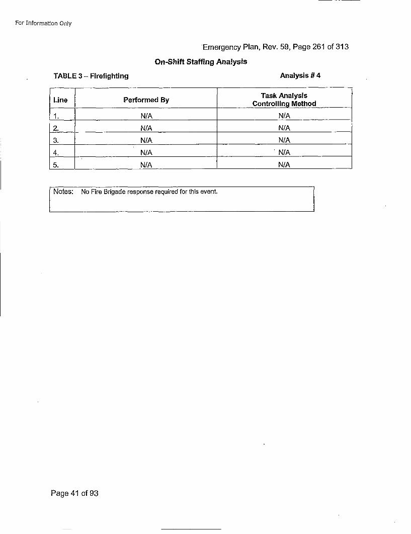
For Information Only
Emergency Plan, Rev. 59, Page 261 of 313
On-Shift Staffing Analysis
Analysis # 4TABLE 3 - Firefighting
LinePerorme ByTask AnalysisLinePerorme ByControlling Method
1. N/A N/A
2. N/A N/A
3. N/A N/A
4. N/A N/A
5. N/A N/A
Notes: No Fire Brigade response required for this event.
Page 41 of 93
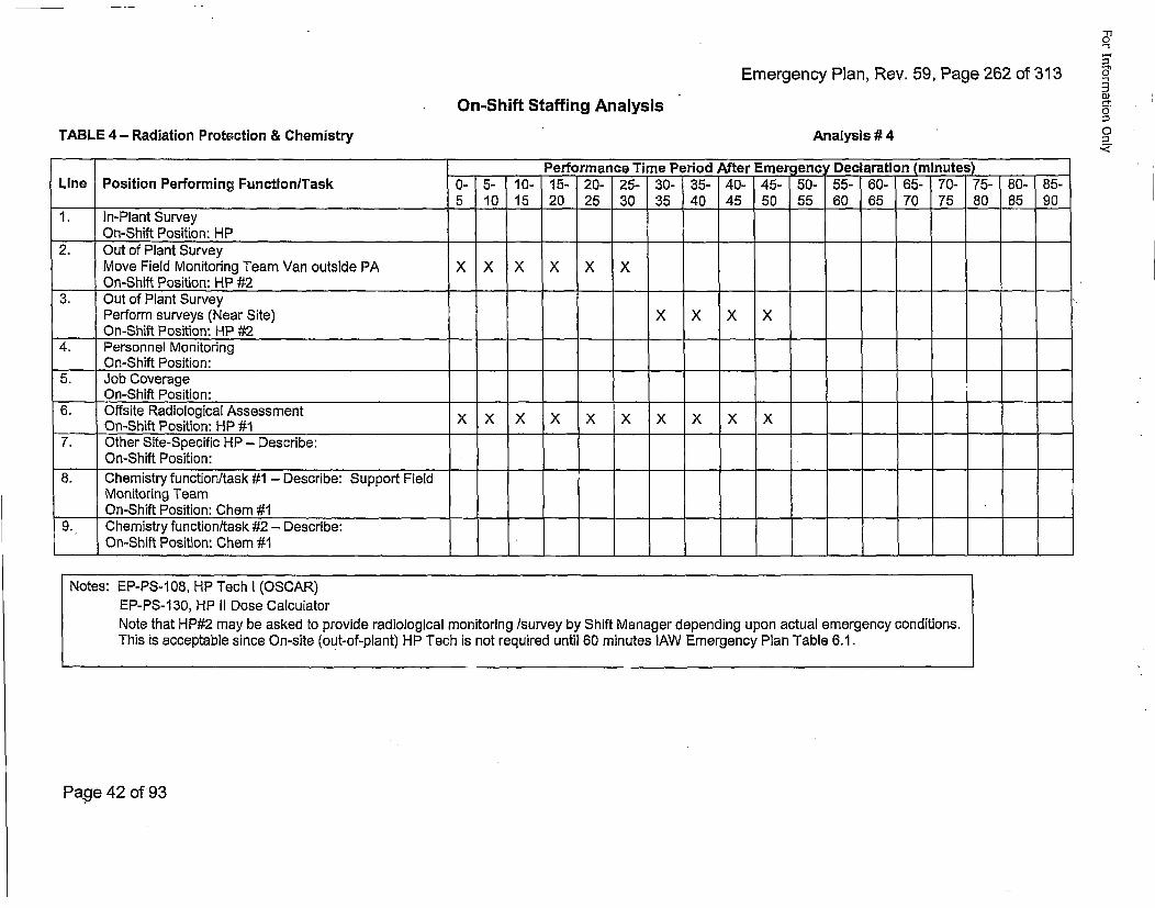
Emergency Plan, Rev. 59, Page 262 of 313
'-r"-I
0"
0]
0On-Shift Staffing Analysis
TABLE 4 - Radiation Protection & Chemistry Analysis # 4
Performance Time Period After Emerqency Declaration (mlnutes).Line Position Performing FunctionlTask 0- 5- 10- 15- 20- 25- 30- 35- 40- 45- 50- 55- 60- 65- 70- 75- 80- 85-
5 10 15 20 25 30 35 40 45 50 55 60 65 70 75 80 85 90'1. In-Plant Survey ..
On-Shift Position: HP2. Out of Plant Survey
Move Field Monitoring Team Van outside PA X X X X X XOn-Shift Position: HP #2
:3. Out of Plant SurveyPerform surveys (Near Site) X X X XOn-Shift Position: HP #2
4. Personnel MonitoringOn-Shift Position:
5. Job CoverageOn-Shift Position:
6. Offsite Radiological Assessment x x x x x x x x xOn-Shift Position: HP #1X X X X X X X X X
7. Other Site-Specific HP - Describe:On-Shift Position:
8. Chemistry function/task #1 - Describe: Support FieldMonitoring Team
___On-Shift Position: Chem #1'9. Chemistry function/task #2 - Describe:'
On-Shift Position: Chain #1
Notes: EP-PS-108, HP Tech I (OSCAR)EP-PS-1 30, HP II Dose CalculatorNote that HP#2 may be asked to provide radiological monitoring /survey by Shift Manager depending upon actual emergency conditions.This is acceptable since On-site (out-of-plant) HP Tech is not required until 60 minutes lAW Emergency Plan Table 6.1.
Page 42 of 93
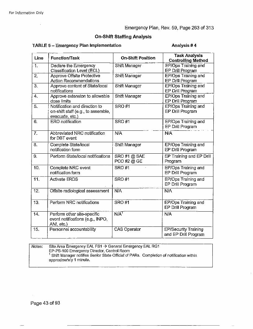
For Information Only
Emergency Plan, Rev. 59, Page 263 of 313
On-Shift Staffing Analysis
TABLE 5 - Emergency Plan Implementation Analysis # 4
Line Function/Task On-Shift PositionTakAlyi
- 1. Declare the Emergency Shift Manager EP/Ops Training andClassification Level (ECL) E rl rga
2. Approve Offsite Protective Shift Manager EP/Ops Training andAction Recommendations ____Drill__Program _
3. Approve content of State/local Shift Manager EP/Ops Training andnotifications EP Drill Program
4. Approve extension to allowable Shift Manager EP/Ops Training anddose limits EP Drill Program
5. Notification and direction to SRO #1 EP/Ops Training andon-shift staff (e.g., to assemble, EP Drill Program
____evacuate, etc.)6. ERO notification SRO #1 EP/Ops Training and
EP Drill Program
7. Abbreviated NRC notification N/A N/Afor DBT event
8. Complete State/local Shift Manager EP/Ops Training andnotification form EP Drill Program
9. Perform State/local notifications SRO #1 @ SAE EP Training and EP DrillPCO #2 @ GE Program
10. Complete NRC event SRO #1 EP/Ops Training andnotification form EP Drill Program
11. Activate ERDS SRO #1 EP/Ops Training andEP Drill Program
12. Offsite radiological assessment N/A N/A
13. Perform NRC notifications SRO #1 EP/Ops Training andEP Drill Program
14. Perform other site-specific N/A1 N/Aevent notifications (e.g., I NPO,AN!, etc.)
15. Personnel accountability CAS Operator EP/Security Trainingand EP Drill Program
Notes: Site Area Emergency EAL FS1 --) General Emergency EAL RG1EP-PS-100 Emergency Director, Control Room' Shift Manager notifies Senior State Official of PARs. Completion of notification withinapproximately 1 minute.
Page 43 of 93
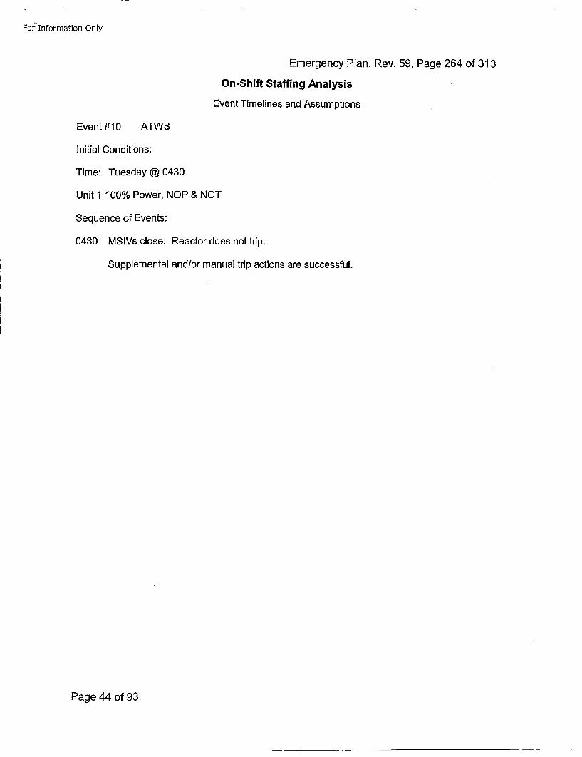
For Information Only
Emergency Plan, Rev. 59, Page 264 of 313
On-Shift Staffing Analysis
Event Timelines and Assumptions
Event #10 ATWS
Initial Conditions:
Time: Tuesday @ 0430
Unit 1 100% Power, NOP & NOT
Sequence of Events:
0430 MSIVs close. Reactor does not trip.
Supplemental and/or manual trip actions are successful.
Page 44 of 93
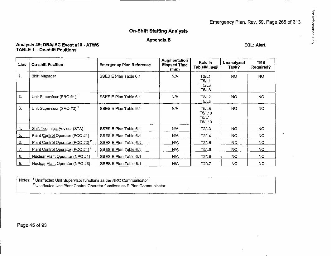
Emergency Plan, Rev. 59, Page 265 of 313
-T1
0"
0
oJ'i.
On-Shift Staffing Analysis
Appendix BAnalysis #5: DBA/ISG Event #10 - ATWSTABLE 1 - On-shift Positions
ECL: Alert
Augmentation Role in Unanalyzed TMSLine On-shift Position Emergency Plan Reference Elapsed Time
____________________ __________________ (min) Table#/Llne# Task? Required?
1. Shift Manager SSES E Plan Table 6.1 N/A T2/L1 NO NOT5/L1T5/L3T5/L8
2. Unit Supervisor (SRO #1) 1SSES E Plan Table 6.1 N/A T2/L2 NO NOT5/L5 _______ _____ __
3. Unit Supervisor (SRO #2) 1 SSES E Plan Table 6.1 N/A T5/L6 NO NOT5/L10T5IL11T5/LI13
4. Shift Technical Advisor (STA) SSES E Plan Table 6.1 N/A T2/L3 NO NO
5. Plant Control Operator (PCO #1) SSES E Plan Table 6.1 N/A T2/L4 NO NO
6. Plant Control Operator (PCO #2) 2 SSES E Plan Table 6.1 N/A T2/L5 NO NO
7. Plant Control Operator (PCO #4)2 SSES E Plan Table 6.1 N/A T5/L9 NO NO
8. Nuclear Plant Operator (NPO #1) SSES E Plan Table 6.1 N/A T2/L6 NO NO
9. Nuclear Plant Operator (NPO #3) SSES E Plan Table 6.1 N/A T2/L7 NO NO
Notes: 1Unaffected Unit Supervisor functions as the NRC Communicator2 UnfetdUnit Plant Control Operator functions as E Plan Communicator
Page 45 of 93
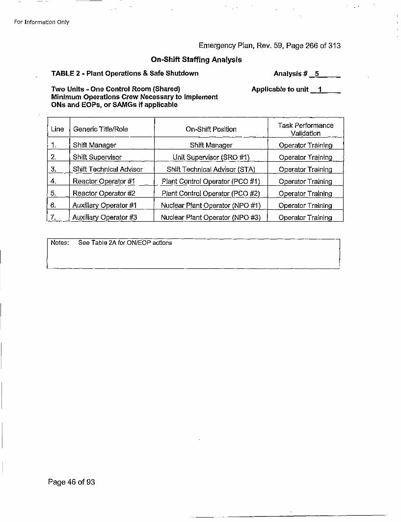
For Information Only
Emergency Plan, Rev. 59, Page 266 of 313On-Shift Staffing Analysis
TABLE 2 - Plant Operations & Safe Shutdown Analysis # 5
Applicable to unit 1Two Units - One Control Room (Shared)Minimum Operations Crew Necessary to ImplementONs and EOPs, or SAMGs if applicable
Task PerformanceLine Generic Title/Role On-Shift Position Vldto
1. Shift Manager Shift Manager Operator Training
2. Shift S~upe~rvisor Unit Supervisor (SRO #1) .. Operator Training
3. Shift Technical Advisor Shift Technical Advisor (STA) .Operator Training
4. Reactor Operator #1 Plant Control Operator (PCO #1 ) Operator Training
5. Reactor Operator #2 Plant Control Operator (PCO #2) 0perator Training
6. Auxiliary Operator #1 Nuclear Plant Operator (NPO #1) ,Operator Training
7. .,Auxiliary Operator #3 Nuclear Plant Operator (NPO #3) Operator Training
Notes: See Table 2A for ON/EOP actions
Page 46 of 93
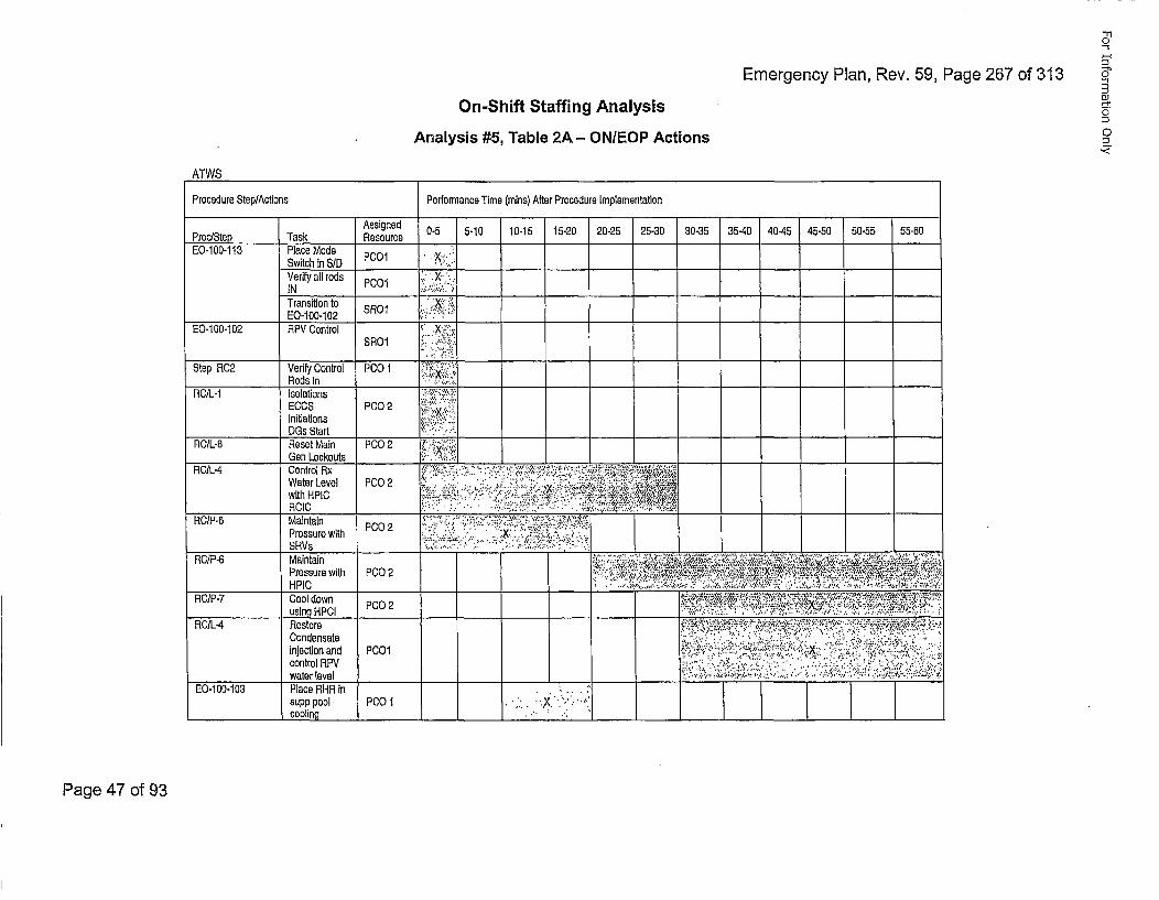
Emergency Plan, Rev. 59, Page 267 of 313
-I
0"
oJ0:
0
On-Shift Staffing AnalysisAnalysis #5, Table 2A - ON/EOP Actions
ATWS
Procedure Step/Actions Pertormance Time (mains) After Procedure Implementation
Assigned 0-5 5-10 10-15 15-20 20-25 25-30 30-35 35-40 40-45 45-50 50-55 55-50Proc/Step Task ResourceE0-100-113 Place Mode
Switch in S/D PC0 :'..: K .,
Verify all rods •. .X-IN PC 1 __.___,:,..•
Transition to SR0I ;X•. :.E0-i100-102 ";:" '
E0-100-102 RPV Control : X'2SRO1
Step RC2 Verify Control PCO 1 x•••;iRods In ... ,_.__:.
RO/L-1 Isolations ;.,'•,.:EGOS PCO02 • .%X•:
Initiations......,.DGs Start _'._.__.._..__-
RCtL-8 Reset Main PC02 •:"•:Gen Lockouts __,..._____.:,,..,____
RO/LL4 Control Rx...;. .. ,.-.. .:.' .,, .-,-- .-. ':.-..... .• ..'....'""-{•4', .';W ater Level PCO02 xo.. ..--.• .,* ...'.-. ,., . .'.: ,•# , ,.., .4 ;•with HPIC -= -'•-'.. .,• .;, .. •. :...- '•••.•.. . •- , .*, ;.••,•,,,
RC/ -6 ainalPressure witth PC02 ;i:. .;..", •."X.::.'i:i., .:';;
RC/P-5 Maintain ••:; ;' '.,;,:. .ii:' i !• •'"":'"' •': •;:•: .... "" • " :: •••" •:Pressure with P00 2 •..,, .; ,•• ,. --,- ,,•..,,,•`:•`?e; ••*!',``:`•;••:••`•••••.
RC/P-7 Cool down ".•,,,.•2' ,., ,• .•..;,.,,,,• •'•.,•"#,;',.•':,,,;,=:÷•,.using HPCI PC02 •••'-•-7 ;•'•• •••:,, .- .,' •, . .- ,;•,.,
RC/L .4 Restore {• T., hT. " 'Y,'.f £.i•T-•,,5;'••;. :,•.~.:.• .',:;. 4 :,-Condensate,....: •: ... . .- ".:. ' ... ' , .•, .- ',injection and PC0O,;'Y'" . . .'" .•. ;••.":•: ..... .: l'•"":'., .;•"-., "control RPVi..: :'-:• :..,.", ,,.'. ' .'. .. ":. ;,,,:.'..'::. ":,,,:.:.•-i! ;''
___________ water level "..:.::.,;•<,,.,.:•:.,s,.,.-• , ,, -r.•..,*. 4...; ... •:.,,•:.,•::.
________________cooling _______________________
Page 47 of 93
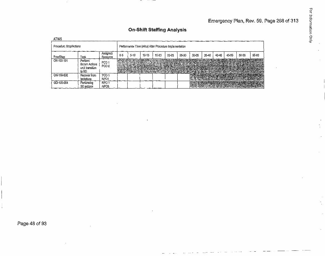
Emergency Plan, Rev. 59, Page 268 of 313
"1"1
u-'1
0
.,
On-Shift Staffing Analysis
ATWS
Procedure Step/Actions Performance Time (rains) After Procedure Implementation
AssignedResource 0-5 15-10 10o-15 15•-20 20-25 125-3o 3o-35 135-40 40-451I45-50 50-55 55-60Proc/Step Task
GON0-00 fPerformn NPO0 1001 Scra Actions NPO2
ON-159-002 l•ecover fromIsolations Po0lNP01
GO-100.004 ( Performing NPO 1 1 ____________________________________________
___________ SD actions L NPO3
Page 48 of 93
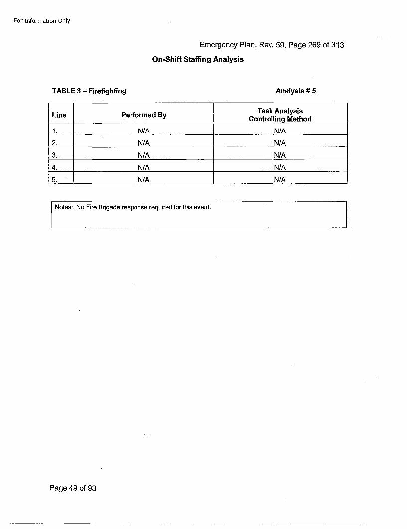
For Information Only
Emergency Plan, Rev. 59, Page 269 of 313On-Shift Staffing Analysis
TABLE 3 - Firefighting Analysis # 5
LinePerorme ByTask AnalysisLine____Per__ormed ____By__Controlling Method
1. N/A N/A
2. N/A N/A
3. N/A N/A
4. N/A N/A
5. N/A N/A
Notes: No Fire Brigade response required for this event.
Page 49 of 93
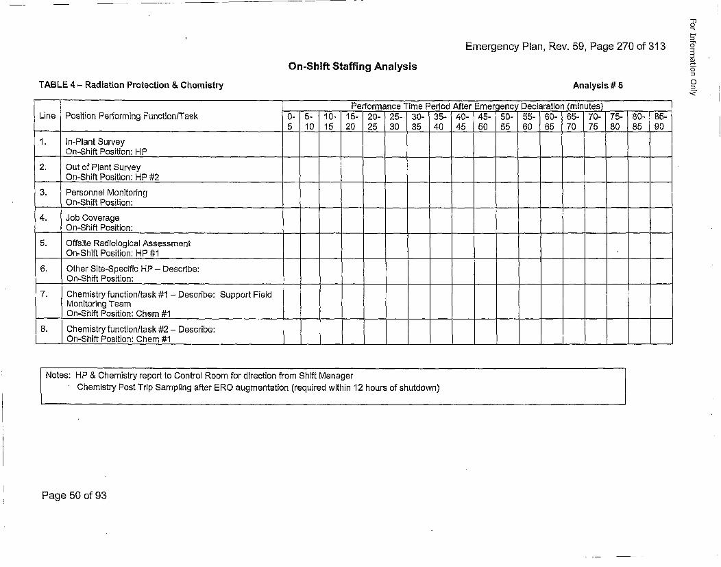
Emergency Plan, Rev. 59, Page 270 of 313
-1310
0"
0
0
On-Shift Staffing Analysis
TABLE 4 - Radiation Protection & Chemistry Analysis #5
Performan~ce Time Period After Emergency Declaration (minutes)Line Position Performing Function/Task 0- 5- 10- 15- 20- 25- 30- 35- 40- 45- 50- 55- 60- 65- 70- 75- 80- 85-___5 10 15 20 25 30 35 40 45 50 55 60 65 70 75 80 85 90
1. In-Plant SurveyOn-Shift Position: HP
2. Out of Plant SurveyOn-Shift Position: HP #2 __
3. Personnel MonitoringOn-Shift Position:
4. Job CoverageOn-Shift Position:
5. Offsite Radiological Assessment___On-Shift Position: HP #1
6. Other Site-Specific HP - Describe:On-Shift Position:
7. Chemistry function/task #1 - Describe: Support FieldMonitoring TeamOn-Shift Position: Chem #1
8. Chemistry function/task #2 - Describe:___On-Shift Position: Chem #1
Notes: HP & Chemistry report to Control Room for direction from Shift ManagerChemistry Post Trip Sampling after ERO augmentation (required within 12 hours of shutdown)
Page 50 of 93
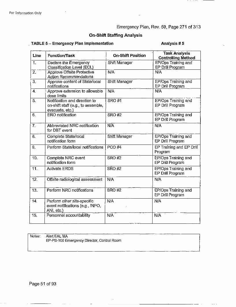
For Information Only
Emergency Plan, Rev. 59, Page 271 of 313On-Shift Staffing Analysis
TABLE 5- Emergency Plan Implementation Analysis # 5
Task AnalysisLine FunctioniTask On-Shift Position CnrligMto
1. Declare the Emergency Shift Manager EP/Ops Training and___Classification Level (ECL) EP Drill Program
2. Approve Offsite Protective N/A N/AAction Recommendations ___________
3. Approve content of State/local Shift Manager EP/Ops Training andnotifications ____________EP Drill Program
4. Approve extension to allowable N/A N/Adose limits
5. Notification and direction to SRO #1 EP/Ops Training andon-shift staff (e.g., to assemble, EP Drill Programevacuate, etc.)
6. ERO notification SRO #2 EP/Ops Training andEP Drill Program
7. Abbreviated NRC notification N/A N/Afor DBT event
8. Complete State/local Shift Manager EP/Ops Tlraining andnotification form EP Drill Program
9. Perform State/local notifications PCO #4 EP Training and EP DrillProgram
10. Complete NRC event SRO #2 EP/Ops Training andnotification form EP Drill Program
11. Activate ERDS SRO #2 EP/Ops Training andEP Drill Program
12. Offsite radiological assessment N/A N/A
13. Perform NRC notifications SRO #2 EP/Ops Training andEP Drill Program
14. Perform other site-specific N/A N/Aevent notifications (e.g., INPO,ANI, etc.) _ _ _ _ _ _ _ _ _ _ _ _ _ _ _ _ _ _ _ _
15. Personnel accountability N/A N/A
Notes: Alert EAL MAEP-PS-1 00 Emergency Director, Control Room
Page 51 of 93
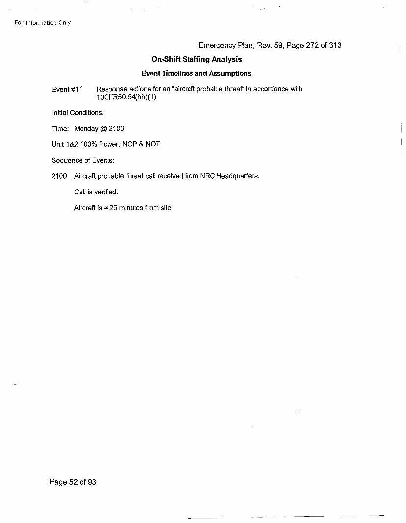
For Information Only
Emergency Plan, Rev. 59, Page 272 of 313
On-Shift Staffing Analysis
Event Timelines and Assumptions
Event #11 Response actions for an "aircraft probable threat'' in accordance with10OCFR50.54(hh)(1)
Initial Conditions:
Time: Monday @ 2100
Unit I&2 100% Power, NOP & NOT
Sequence of Events:
2100 Aircraft probable threat call received from NRC Headquarters.
Call is verified.
Aircraft is =25 minutes from site
Page 52 of 93
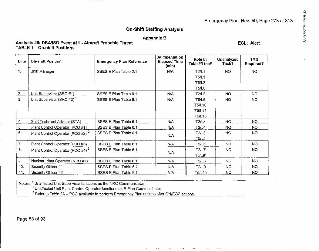
Emergency Plan, Rev. 59, Page 273 of 313
-n10
£0
0
0
On-Shift Staffing Analysis
Appendix BAnalysis #6: DBA/ISG Event #11 - Aircraft Probable ThreatTABLE 1 - On-shift Positions
ECL: Alert
Augmentation Role in Unanalyzed TMSLine On-shift Position Emergency Plan Reference Elapsed Time(m) Table#/Line# Task? Required?
1. Shift Manager SSES E Plan Table 6.1 N/A T2/L1 NO NO
T5/LIT5/L3T5/L8_______
2. Unit Supervisor (SRO #1) 1 SSES E Plan Table 6.1 N/A T2/L2 NO NO3. Unit Supervisor (SRO #2) 1 SSES E Plan Table 6.1 N/A T5/L6 NO NO
T5/LIO
T5/LI3
4. Shift Technical Advisor (STA) SSES E Plan Table 6.1 N/A T2/L3 NO NO5. Plant Control Operator (PC0 #1) SSES E Plan Table 6.1 N/A T2/L4 NO NO6. Plant Control Operator (PC0 #2) 2 SSES E Plan Table 6.1 NAT2/L5 NO NO
N/A T5/L57. Plant Control Operator (PCO #3) SSES E Plan Table 6.1 N/A T2/L6 NO NO6. Plant Control Oeao(PO#)2 SSES E Plan Table 6.1 T2/L7 NO NO
Opeatr P0 ~N/A T5/L9 3 ______
9. Nuclear Plant Operator (NPO #1) SSES E Plan Table 6.1 N/A T2/L8 NO NO10. Security Officer #1 SSES E Plan Table 6.1 N/A T2/L9 NO NO11. Security Officer #2 SSES E Plan Table 6.1 N/A T5/L14 NO NO
Notes: ' Unaffected Unit Supervisor functions as the NRC Communicator2Unaffected Unit Plant Control Operator functions as E Plan Communicator
3 Refer to Table 2A - PCO available to perform Emergency Plan actions after ON/EOP actions.
Page 53 of 93
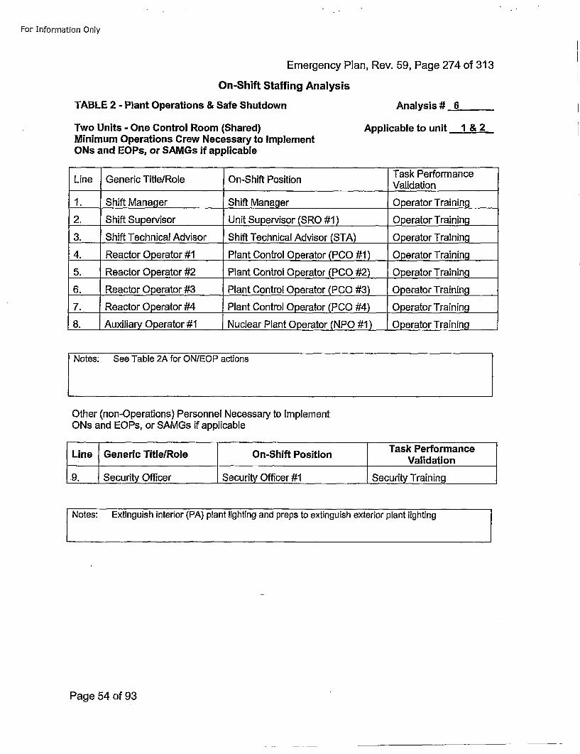
For Information Only
Emergency Plan, Rev. 59, Page 274 of 313On-Shift Staffing Analysis
TABLE 2 - Plant Operations & Safe Shutdown Analysis # 6
Two Units - One Control Room (Shared)Minimum Operations Crew Necessary to ImplementONs and EOPs, or SAMGs if applicable
Applicable to unit 1 & 2
Task PerformanceLine Generic Title/Role On-Shift Position Vldto
1. Shift Manager Shift Manager Operator Training .
2. Shift Supervisor Unit Supervisor (SRO #1) 0perator Training
3. Shift Technical Advisor Shift Technical Advisor (STA) Opera~tor Training
4. Reactor Operator #1 Plant Control Operator (PCO #1) Operator Training
5. Reactor Operator #2 Plant Control Operator (PCO #2) 0perator Training
6. Reactor Operator #3 Plant Control Operator (PCO #3) Operator Training
7. Reactor Operator #4 Plant Control Operator (PCO #4) Operator Training
8. Auxiliary Operator #1 Nuclear Plant Operator (NPO #1) Operator Training
Other (non-Operations) Personnel Necessary to ImplementONs and EOPs, or SAMGs if applicable
[ Task PerformanceLine Generic TitlelRole On-Shift Position Vldto
1 . Securit Officer Security Officer #1 Securit Training
INotes: Extinguish interior (PA) plant lighting and preps to extinguish exterior plant lighting
Page 54 of 93
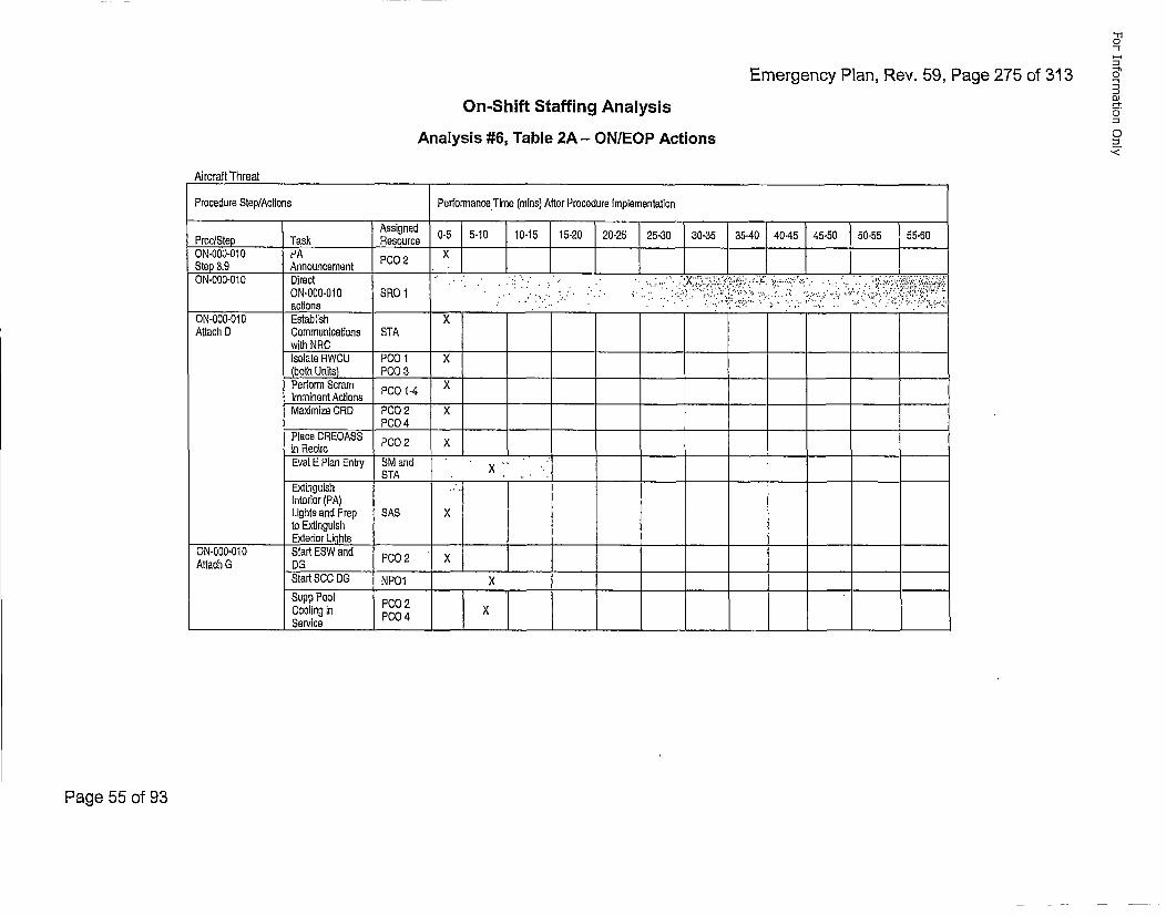
Emergency Plan, Rev. 59, Page 275 of 313
-510
51
n0-
oJ
0<
On-Shift Staffing AnalysisAnalysis #6, Table 2A - ONIEOP Actions
Aircraft Threat
Procedure Step/Actions Performance.Time (mins) After Procedure Implementation
PrcSeAakRsourced 0-5 5-10 10-15 15-20 20-25 25-30 30-35 35-40 40-45 45-50 50-55 55-60
ON-O00-01 0 PA [ _O_2_X
Step 3.9 Announcement P02 XL______________________ ________
ON-000-010 Direct1 -O N... ..-..... . .. . .. ... . .... S.... .. .O -O -lactions .R1i I? • ' . ! ' . " ! . .. •;' ;';..-. :.-.• :. :. .. ' ":.;":=' ?••o,
ON-O00-O10 Establish XAttach 0 Communications STA
with NRCIsolate RWCU P00 1 X(both Units) PCO03Perform ScramXImminent Actions P00 1-4Maximize CRD PCO02 X
PCO4 4__Place CREOASS P0in RaciroEval EPlan Entry SM and x-
STA ..,Extinguish .
Interior (PA)Lights and Prep SAS Xto Extinguish
_______________Exterior Lights ____________________ _______________________
ON-gO0-010 Start ESW and P00 2 XAttach G OG______
Start SOC OG N P01 XSupp Pool PCO02Cooling In P00 4 XService ____ __I___ _______________________________
Page 55 of 93
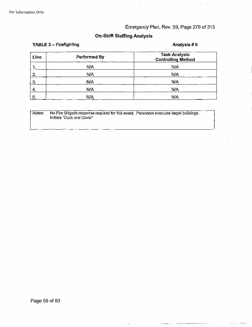
For Information Only
Emergency Plan, Rev. 59, Page 276 of 313On-Shift Staffing Analysis
TABLE 3 - Firefighting Analysis # 6
LinePerorme ByTask AnalysisLinePerorme ByControlling Method
1. N/A N/A
2. N/A N/A
3. N/A N/A
4. N/A N/A
5. N/A N/A
Page 56 of 93
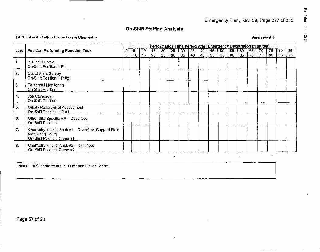
Emergency Plan, Rev. 59, Page 277 of 313
'-nO
8"
oh
0
Di0,
On-Shift Staffing Analysis
TABLE 4 - Radiation Protection & Chemistry Analysis # 6
Performance Time Period After Emergency Declaration (minutes)Line Position Performing FunctionlTask 0- 5- 10- 15- 20- 25- 30- 35- 40- 45- 50-/55- 60- 65- 70- 75- 80- 85-
5 10 15 20 25 30 35 40 45 50 55 60 65 70 75 80 85 901. In-Plant Survey
On-Shift Position: HP
2. Out of Plant Survey___On-Shift Position: HP #2
3. Personnel MonitoringOn-Shift Position:
4. Job CoverageOn-Shift Position:
5. Offsite Radiological AssessmentOn-Shift Position: HP #1
6. Other Site-Specific HP - Describe:On-Shift Position:
7. Chemistry function/task #1 - Describe: Support FieldMonitoring TeamOn-Shift Position: Chem #1
8. Chemistry function/task #2 - Describe:___On-Shift Position: Chem #1
Notes: HP/Chemistry are in 'Duck and Cover" Mode.
Page 57 of 93
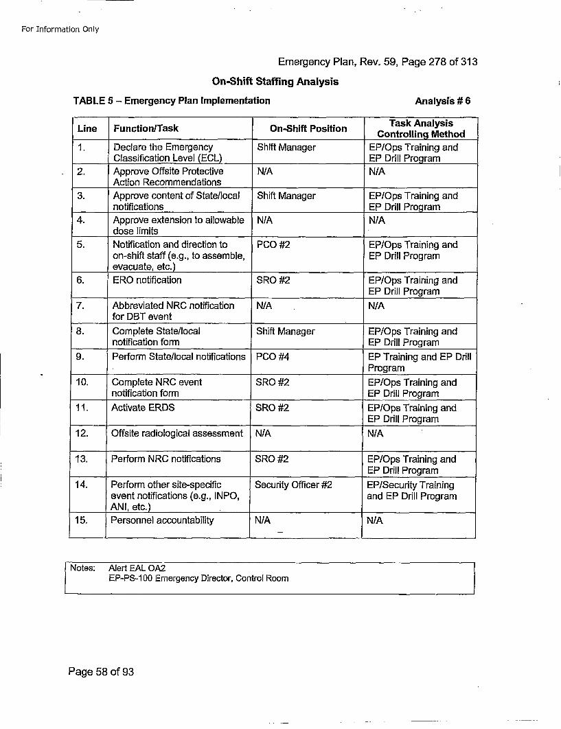
For Information Only
Emergency Plan, Rev. 59, Page 278 of 313On-Shift Staffing Analysis
TABLE 5 - Emergency Plan Implementation Analysis # 6
Line FunctionlTask On-Shift Position CnrligMto
1. Declare the Emergency Shift Manager EP/Ops Training andClassification Levei (ECL) E rl rga
2. Approve Offsite Protective N/AN/Action Recommendations ___________
3. Approve content of State/local Shift Manager EP/Ops Training andnotifications ___________EP Drill Program
4. Approve extension to allowable N/A N/Adose limits_______ _____
5. Notification and direction to PCO #2 EP/Ops Training andon-shift staff (e.g., to assemble, EP Drill Programevacuate, etc.) ___________
6. ERO notification SRO #2 EP/Ops Training and______EP Drill Program
7. Abbreviated NRC notification N/A N/A____for DBT event
8. Complete State/local Shift Manager EP/Ops Training andnotification form EP Drill Program
9. Perform State/local notifications PCO #4 EP Training and EP DrillProgram
10. Complete NRC event SRO #2 EP/Ops Training andnotification form EP Drill Program
11. Activate ERDS SRO #2 EP/Ops Training and_____________________EP Drill Program
12. Offsite radiological assessment N/A N/A
13. Perform N RC notifications SRO #2 EP/Ops Training and____ _ _ ___ ___ ____ ___ ___ ___ ____ ___ ___ ___ ___ EP Drill Program
14. Perform other site-specific Security Officer #2 EP/Security Trainingevent notifications (e.g., INPO, and EP Drill ProgramANI, etc.)_ _ _ _ _ _ _ _ _ _
15. Personnel accountability N/A N/A
Notes: Alert EAL OA2EP-PS-1 00 Emergency Director, Control Room
Page 58 of 93
For Information Only
Emergency Plan, Rev. 59, Page 279 of 313
On-Shift Staffing Analysis
Event Timelines and Assumptions
Event #12 Control room fire leading to evacuation and remote shutdown
initial Conditions:
Time: Monday @ 0330
Unit 1&2 100% Power, NOP & NOT
Sequence of Events:
0330 Smoke, sparks and flames observed coming from back of control board
Fire Brigade activated
0332 Fire Operations attempt to extinguish flames without success - fire and smoke affectsoperation of both units 1&2
0340 Decision to evacuate Control Room 1 &2
Page 59 of 93
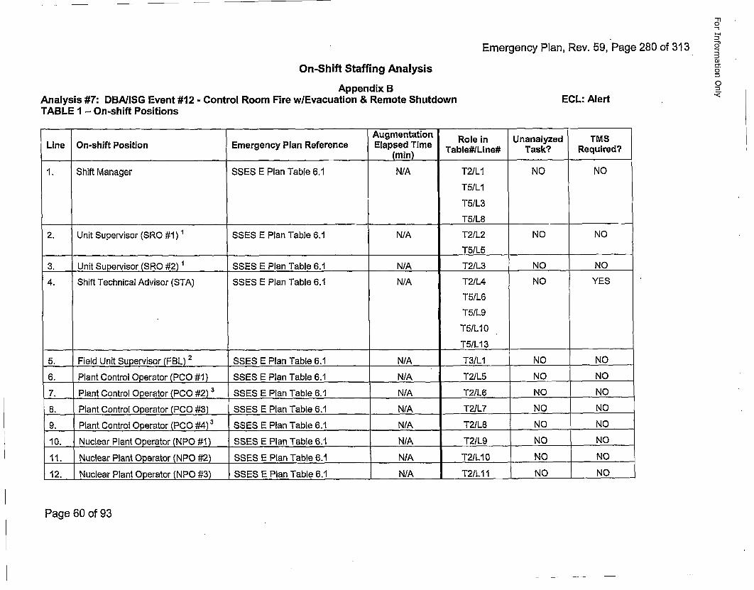
Emergency Plan, Rev. 59, Page 280 of 313
S'-
0
On-Shift Staffing AnalysisAppendix B
Analysis #7: DBA(ISG Event #12 - Control Room Fire wlEvacuation & Remote ShutdownTABLE 1 - On-shift Positions
0
ECL: Alert -
Lie n-hit oitonEmrgnc la Rfeene Augmentation Role in Unanalyzed TMSLin O-sif PsitonEmrgnc Pln efrece Elapsed Time Table#/Line# Task? Required?(min) _____
1. Shift Manager SSES E Plan Table 6.1 N/A T2/LI NO NO
T5/L1
T5/L3
T5/L8
2. Unit Supervisor (SRO #1) SSES E Plan Table 6.1 N/A T2/L2 NO NO
T5/L5
3. Unit Supervisor (SRO #2) 1 SSES E Plan Table 6.1 N/A T21L3 NO NO4. Shift Technical Advisor (STA) SSES E Plan Table 6.1 N/A T2/L4 NO YES
T51L6
T51L9
T5IL10
T5/L13
5. Field Unit Supervisor (FBL) 2 SSES E Plan Table 6.1 NAT3/LI NO _.NO
6. Plant Control 0perator (PCO #1) SSES E Plan Table 6.1 N/A_____ T21L5 NO NO7. Plant Control Operator (PCO #2) 3 SSES E Plan Table 6.•1,/ T2/L6 NO NO
8. Plant Control Operator (PCO #3) SSES E Plan Table 6.1 NAT21L7 NO NO
9. Plant Control Operator (PCO #4) 3 SSES E Plan Table 6.1 N./..A___ T2/L8 NO ... NO
10. Nuclear Plant Operator (NPO #1) SSES E Plan Table 6.1 N/A T21L9 NO NO
11. Nuclear Plant Operator (NPO #2) SSES E Plan Table 6.1 N/A T2/L10 NO NO
12. Nuclear Plant Operator (NPO #3) SSES E Plan Table 6.1 N/A T2/LII NO NO
Page 60 of 93
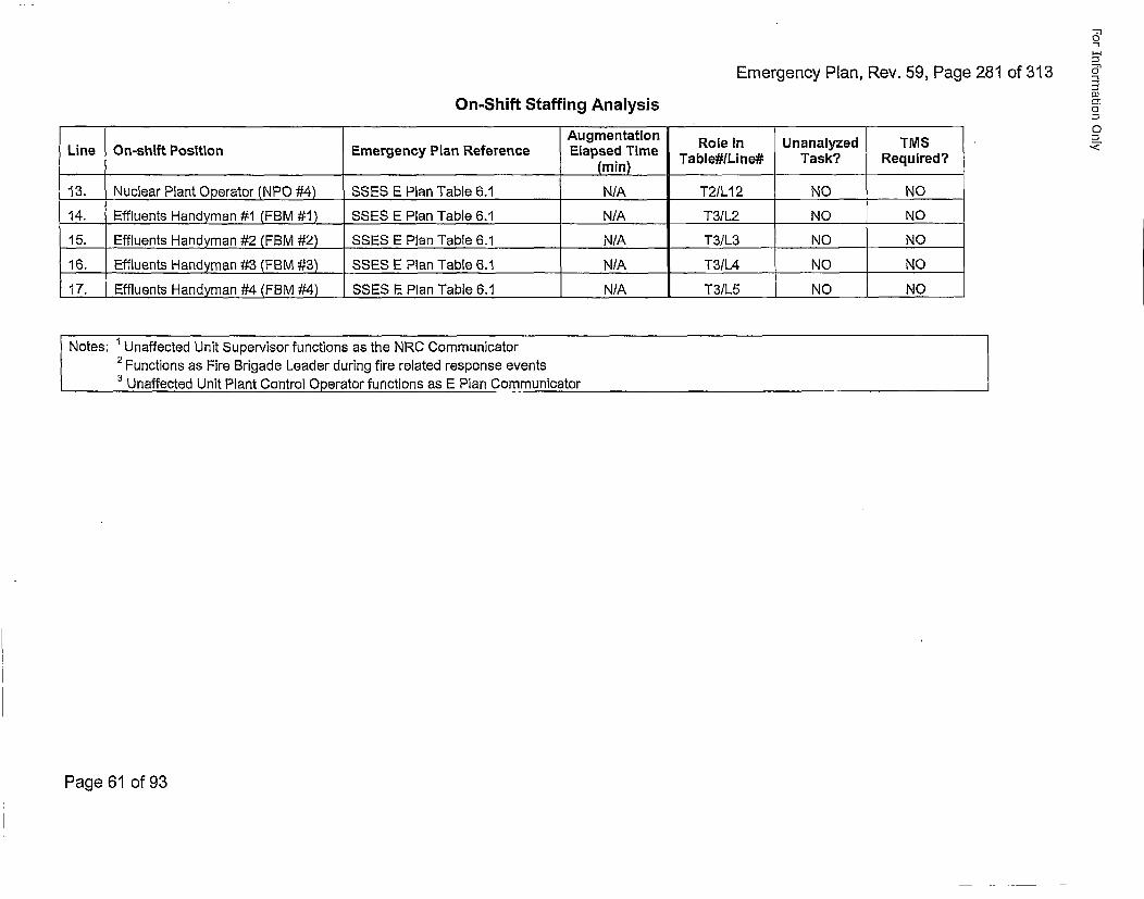
Emergency Plan, Rev. 59, Page 281 of 313
-1r10
5"
O1
On-Shift Staffing Analysis
Line On-shift Position Emergency Plan ReferenceAugmentationElapsed Time
(raini
Role inTable#/Line#
UnanalyzedTask?
TMSRequired?
13. Nuclear Plant Operator (NPO #4) SSES E Plan Table 6.1 N/A T21L12 NO NO
14. Effluents Handyman #1 (FBM #1) SSES E Pl~an Table 6.1 N/A T3/L2 NO NO
15. Effluents Handyman #2 (FBM #2) SSES E Plan Table 6.1 N/A T3/L3 NO NO
16. Effluents Handyman #3 (FBM #3) SSES E Plan Table 6.1 N/A T31L4 NO NO
17. Effluents Handyman #4 (FBM #4) SSES E Plan Table 6.1 N/A T3/L5 NO N.O.
SNotes: ' Unaffected Unit Supervisor functions as the NRC Communicator2 Functions as Fire Brigade Leader during fire related response events3 Unaffected Unit Plant Control Operator functions as E Plan Communicator
Page 61 of 93
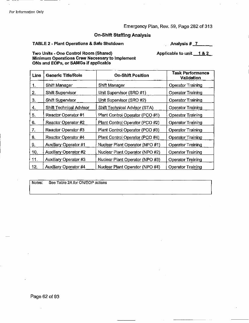
For Information Only
Emergency Plan, Rev. 59, Page 282 of 313On-Shift Staffing Analysis
TABLE 2 - Plant Operations & Safe Shutdown
Two Units - One Control Room (Shared)Minimum Operations Crew Necessary to ImplementONs and EOPs, or SAMGs if applicable
Analysis # 7
Applicable to unit 1 & 2
Line Generic TitlelRole On-Shift Position Ts efracValidation
1. Shift Manager Shift Manager Operator Training
2. Shift Supervisor Unit Supervisor (SRO #1) Operator Training
3. Shift Supervisor Unit Supervisor (SRO #2) Operator Training
4. Shift Technical Advisor Shift Technical Advisor (STA) Operator Training
5. Reactor Operator #1 Plant Control Operator (PCO #1) Operator Training
6. Reactor Operator #2 Plant Control Operator (PCO #2) Operator Training
7. Reactor Operator #3 Plant Control Operator (PC0 #3) Operator Training
8. Reactor Operator #4 Plant Control Operator (PCO #4) Operator Training
9. Auxiliary Operator #1 Nuclear Plant Operator (NPO #1 ) 0perator Training
10. Auxiliary Operator #2 Nuclear Plant Operator (NPO #2) Operator Training
11. Auxiliary Operator #3 Nuclear Plant Operator (NPO #3) 0perator Tra~ining
12. Auxiliary Operator #4 Nuclear Plant Operator (NPO #4) Operator Training
t Notes: See Table 2A for ON/EOP actions
Page 62 of 93
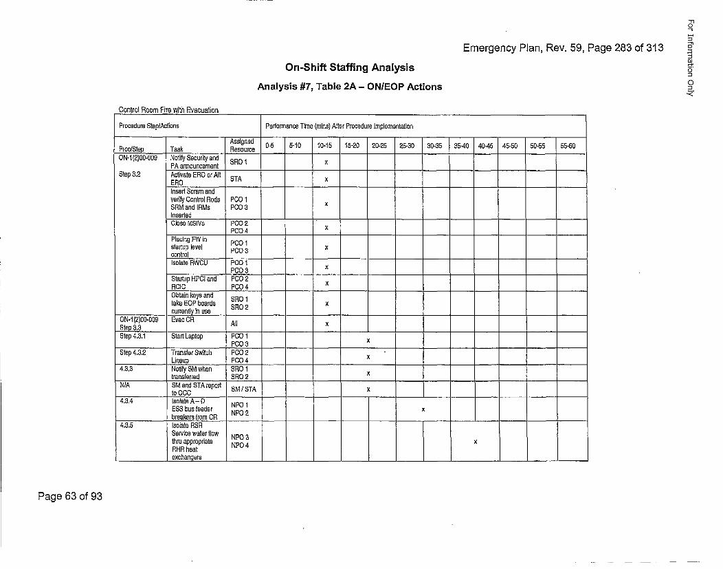
Emergency Plan, Rev. 59, Page 283 of 313
"rlo
t-4,
oOn-Shift Staffing Analysis
Analysis #7, Table 2A - ONIEOP Actions
Control Room Fire with Evacuation _________________________________________________
Procedure Step/Actions Performance Time (mine) After Procedure lImplementaticn
Assigned 0-5 5-10 10-15 15-20 20-25 25-30 30-35 35-40 40-45 45-50 50-55 55-60Proc/Step Task ResourceON-i1(2)00-009 Notify Security and SRO1x
PA announcementXStep 3.2 Activate ERO or Alt STA x
ERO_____ _
insert Scram andverify Control Rods PCO 1SRM and IRMs P0O03 xInsertedClose MSIVs PCO02
PCO04 xPlacing FW in P00 1startup level PCO03 xcontrol _____ ___
Isolate RWCU P00 1PCO 3 x
Startup HPCI and P00 2ROIC PCO04 XObtain keys and SR 1take EOP boards SRO 2 x
______________ currently in use ____
ON-i1(2)00-009 Evac OR All xStep 3.3 _______ ___
Step 4.3.1 Start Laptop P00 1PCO03 x
Step 4.3.2 Transfer Switch PCO02Lineup P00 4 X
4.3.3 No~tiy SM when SRO 1transferred SRO 2 x
N/A SM and STA report SM / STA xto 0C0
4.3.4 Isolate A- 0ESS bus feeder NP1breakers from OR NP2
4.3.5 Isolate RSRService water tiow NPO 3thru appropriate NPO 4XRHR heatexchangers _________________ ___ __________________________________
Page 63 of 93
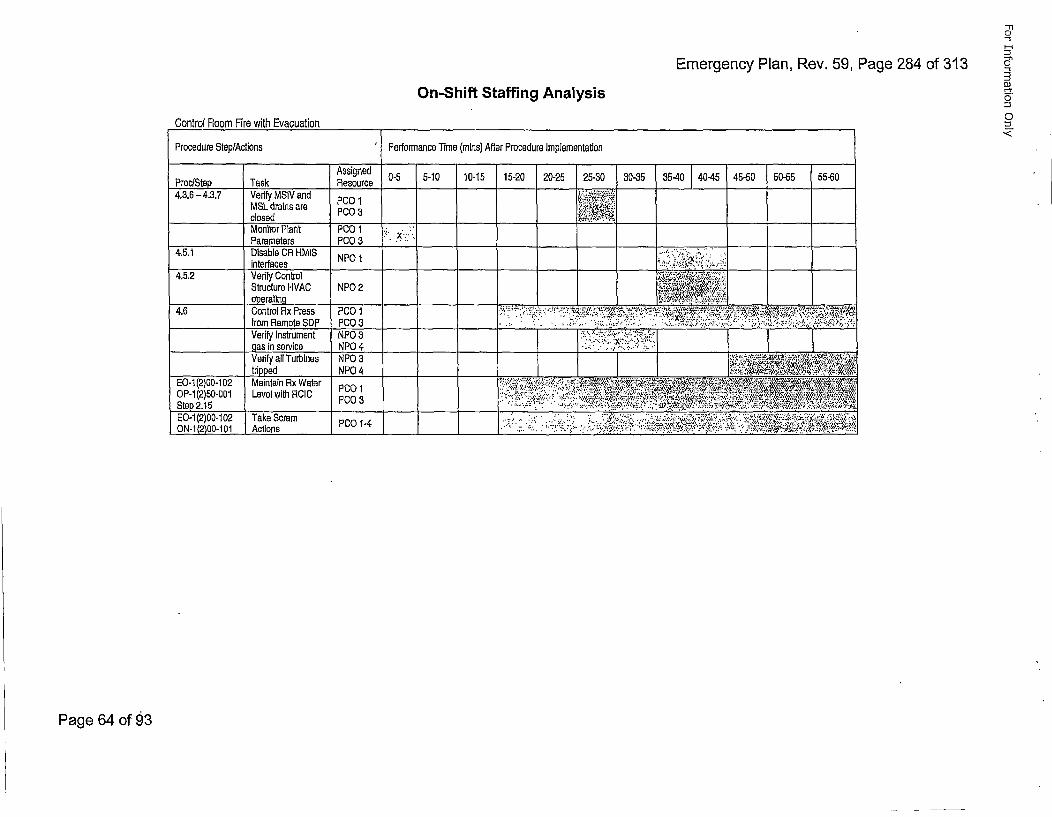
Emergency Plan, Rev. 59, Page 284 of 313
'-10
5a
O)
0
C,
On-Shift Staffing Analysis
Control Room Fire with Evacuation
Procedure Step/Actions Performance Time (mains) After Procedure implementation
Assigned 0-5 5-10 10-15 15-20 20-25 25-30 30-35 35-40 40-45 45-50 50-55 55-60Proc/Step Task Resource,..4,3.6- 4.3.7 Verify MSiV and PC 1 •••.' '
MSL drains are P003.'•closed PO3 , .-',Monitor Plant P00 1 "x.,:'Parameters PCO 3 ..
4.5.1 Disable CR HMIS NPO 1 ..• ,:Li:'.:..,,interfaces
4,5.2 Verify Controi • ... ",",;....Structure HVAC NPO 2 •! x i!,'.,,operating , ,. ,:!:,
4.6 Control Rx Press PCO 1 •'.,., .,•, ,;•+,,.••'.•. ',€ ">•-, *.,'., :,,..;;. ••••'.',•, •••,•,•,from Remote SOP PCO 3.. • :. . .. ;"..:.• ;':, ,:. .. : ..• •.2-...:•:.. " .-.. ',.,.:..,. o ;,., , .Verify Instrument NPO03 .." #:"''': ::':••#'x•:• • :gas in service NPO 4 ... ". . P•' "
Verify all Turbines NPO 3 : ••'""' " : -:>:•*•'•frippad NPO 4 •"•:;#•;•, ,5: :t; •'!:
EQ-i1(2)00-102 Maintain Rx Water PC "•: );..:i; (* .* ,','••.•7.",*/,,,, ,.. ,'2 ' •: '. • '•,•, ;4:i ',•OtP-(2)5,015 LvlwihRI PC0 •.:.•:.'... :". "':;;,:'.*..y4 ;;.•': , • ,•t••; •-,•?. ,.;• ;.•., . ;•,:.•
E0 1(O 0-02 T ke(2a)PO0-0-102.. ... •....Take Scram...,.,, -P001...-4 ., .,. ::. ..... •.•L•,.,• ..... ,. ... ,. ,.,,, ..
Page 64 of 93
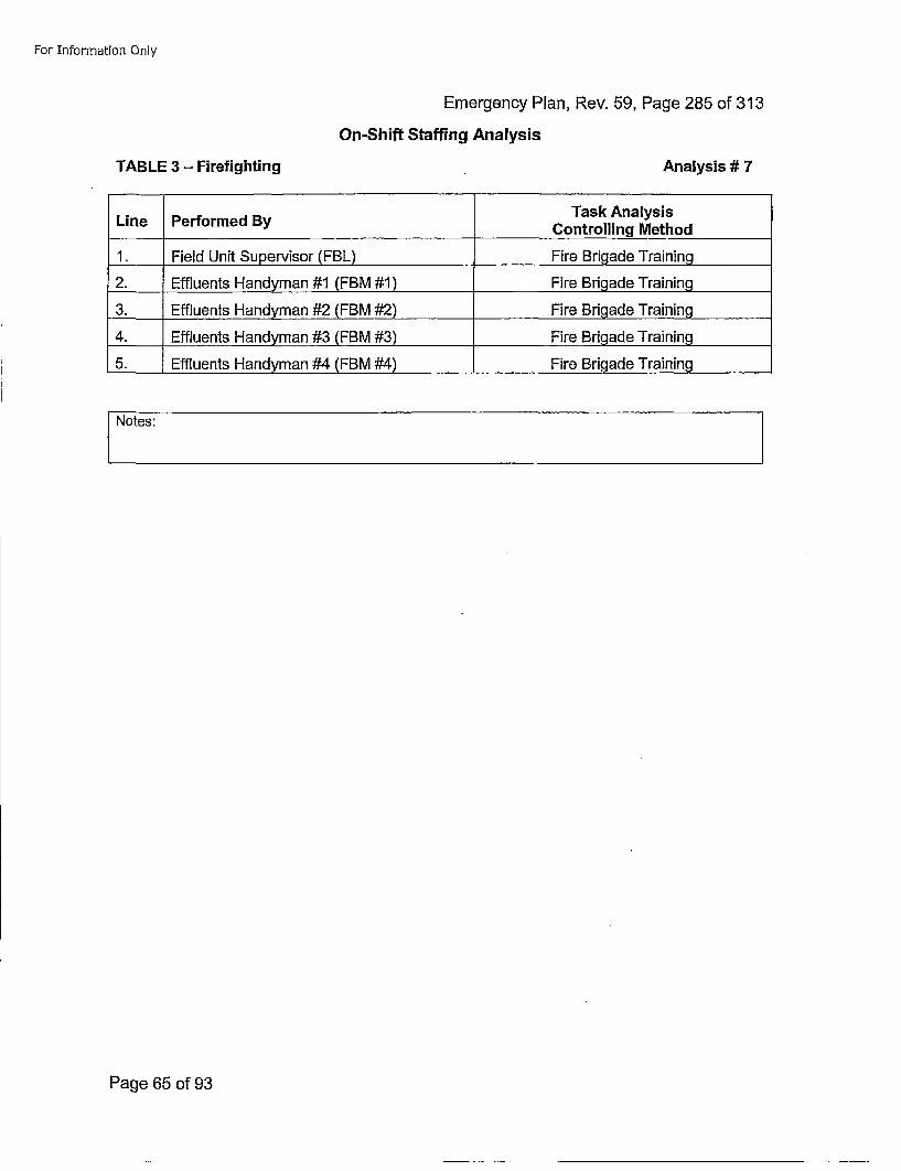
For Information Only
Emergency Plan, Rev. 59, Page 285 of 313On-Shift Staffing Analysis
TABLE 3 -Firefighting Analysis # 7
Line Perorme ByTask AnalysisLine Perorme ByControlling Method
1. Field Unit Supervisor (FBL) Fire Brigade Training
2. Effluents Handyman #1 (FBM #1) Fire Brigade Training
3. Effluents Handyman #2 (FBM #2) Fire Brigade Training
4. Effluents Handyman #3 (FBM #3) Fire Brigade Training
5. Effluents Handyman #4 (FBM #4) Fire Brigade Training
Notes:
Page 65 of 93
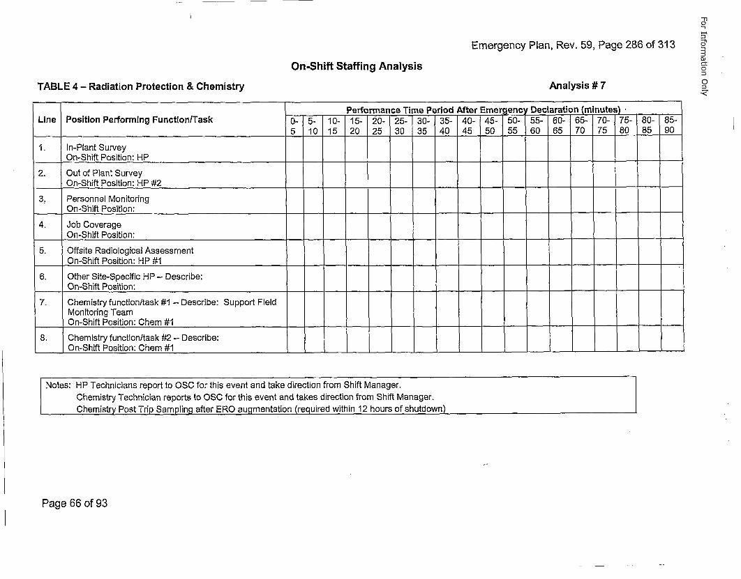
Emergency Plan, Rev. 59, Page 286 of 313
-T10
-I
OJo-tOn-Shift Staffing Analysis
TABLE 4 - Radiation Protection & Chemistry Analysis # 7
Performance Time Period After Emergency Declaration (mnutes)~Line Position Performing Function/Task 0- 5- 10- 15- 20- 25- 30- 35- 40- 45- 50- 55- 60- 65- 70- 75- 80- 85-
5 10 15 20 25 30 35 40 45 50 55 60 65 70 75 80 85 90
1. In-Plant SurveyOn-Shift Position: HP
2. Out of Plant SurveyOn-Shift Position: HP #2
3. Personnel MonitoringOn-Shift Position:__-
- -
4. Job CoverageOn-Shift Position:-
- -
5, Offsite Radiological AssessmentOn-Shift Position: HP #1---
6. Other Site-Specific HP - Describe:On-Shift Position: __
7. Chemistry function/task #1 - Describe: Support FieldMonitoring Team
__On-Shift Position: Chem #1----- - - --
8. Chemistry function/task #2 - Describe:On-Shift Position: Chem #1 _ _ - - _
SNotes: HP Technicians report to OSC for this event and take direction from Shift Manager.Chemistry Technician reports to OSO for this event and takes direction from Shift Manager.Chemistry Post Trip Sampling after• ERO augmentation (required within 12 hours of shutdown)}
Page 66 of 93
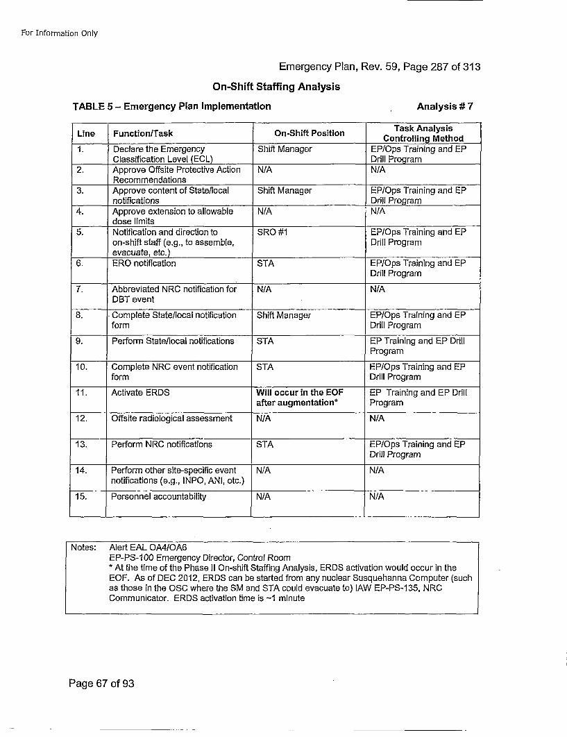
For Information Only
Emergency Plan, Rev. 59, Page 287 of 313On-Shift Staffing Analysis
TABLE 5 - Emergency Plan Implementation Analysis# 7
Line Function/Task On-Shift PositionTakA lyi
1. Declare the Emergency Shift Manager EP/Ops Training and EP____Classification Level (ECL)DrlPora
2. Approve Offsite Protective Action N/AN/Recommendations
3. Approve content of State/local Shift Manager EP/Ops Training and EPnotifications Drill Program
4. Approve extension to allowable N/A N/Adose limits
5. Notification and direction to SRO #1 EP/Ops Training and EPon-shift staff (e.g., to assemble, Drill Programevacuate, etc.)____________
6. ERO notification STA EP/Ops Training and EPDrill Program
7. Abbreviated NRC notification for N/A N/ADBT event
8. Complete State/local notification Shift Manager EP/Ops Training and EPform Drill Program
9. Perform State/local notifications STA EP Training and EP DrillProgram
10. Complete NRC event notification STA EP/Ops Training and EPform Drill Program
11. Activate ERDS Will occur in the EOF EP Training and EP Drillafter augmentation* Program
12. Offsite radiological assessment N/A N/A
13. Perform NRC notifications STA EP/Ops Training and EPDrill Program
14. Perform other site-specific event N/A N/Anotifications (e.g., INPO, ANI, etc.)
15. Personnel accountability N/A N/A
Notes: Alert EAL 0A4/OA6EP-PS-100 Emergency Director, Control Room* At the time of the Phase II On-shift Staffing Analysis, ERDS activation would occur in theEOF. As of DEC 2012, ERDS can be started from any nuclear Susquehanna Computer (suchas those in the OSC where the SM and STA could evacuate to) lAW EP-PS-1 35, NRCCommunicator. ERDS activation time is -1 minute
Page 67 of 93
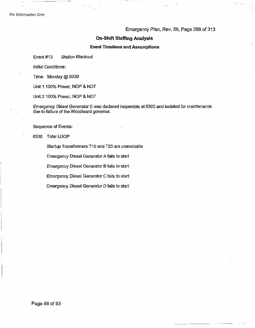
For Information Only
Emergency Plan, Rev. 59, Page 288 of 313On-Shift Staffing Analysis
Event Timelines and Assumptions
Event #13 Station Blackout
Initial Conditions:
Time: Monday @ 0330
Unit 1 100% Power, NOP & NOT
Unit 2 100% Power, NOP & NOT
Emergency Diesel Generator E was declared inoperable at 0300 and isolated for maintenance
due to failure of the Woodward governor.
Sequence of Events:
0330 Total LOOP
Startup Transformers TI10 and T20 are unavailable
Emergency Diesel Generator A fails to start
Emergency Diesel Generator B fails to start
Emergency Diesel Generator C fails to start
Emergency Diesel Generator D fails to start
Page 68 of 93
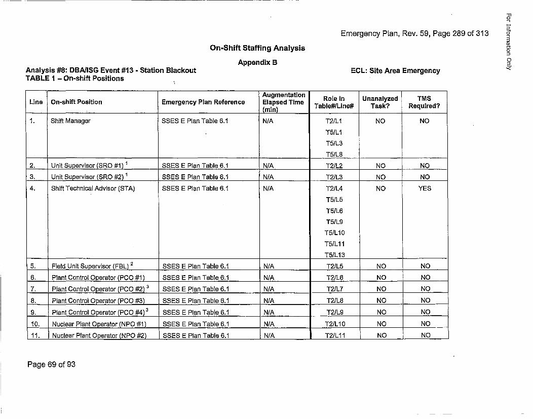
Emergency Plan, Rev. 59, Page 289 of 313
"-n0
0"
03On-Shift Staffing Analysis
Appendix B 0ECL: Site Area Emergency •
Analysis #8: DBAIISG Event #13 - station BlackoutTABLE 1 - On-shift Positions
Augmentation Role in Unanalyzed TMSLine On-shift Position Emergency Plan Reference Elapsed Time
mmTable#ILine# Task? Required?
1. Shift Manager SSES E Plan Table 6.1 N/A T2/LI NO NO
T5ILI
T5/L3
________________________T5/L8
2. Unit Supervisor (SRO #1) ' SSES E Plan Table 6.1 N/A T2/L2 NO NO
3. Unit Supervisor (SRO #2) 1 SSES E Plan Table 6.1 N/A T2/L3 NO NO
4. Shift Technical Advisor (STA) SSES E Plan Table 6.1 N/A T2/L4 NO YES
T51L5
T51L6
T51L9
T5/LI10
T5/L11
T5/L13 ______
5. Field Unit Supervisor (FBL) 2 SSES E Plan Table 6.1 N/A T21L5 NO NO
6. Plant Control Operator (PCO #1) SSES E Plan Table 6.1 N/A T2/L6 NO NO
7. Plant Control Operator (PCO #2) 3 SSES E Plan Table 6.1 N/A T2/L7 NO NO
8. Plant Control Operator (PCO #3) SSES E Plan Table 6.1 N/A T21L8 NO NO
9. Plant Control Operator (PCO #4)3 SSES E Plan Table 6.1 N/A T21L9 NO NO
10. Nuclear Plant Operator (NPO #1) SSES E Plan Table 6.1 N/A T2/LI 0 NO NO
11. Nuclear Plant Operator (NPO #2) SSES E Plan Table 6.1 N/A T2/L11I NO NO
Page 69 of 93
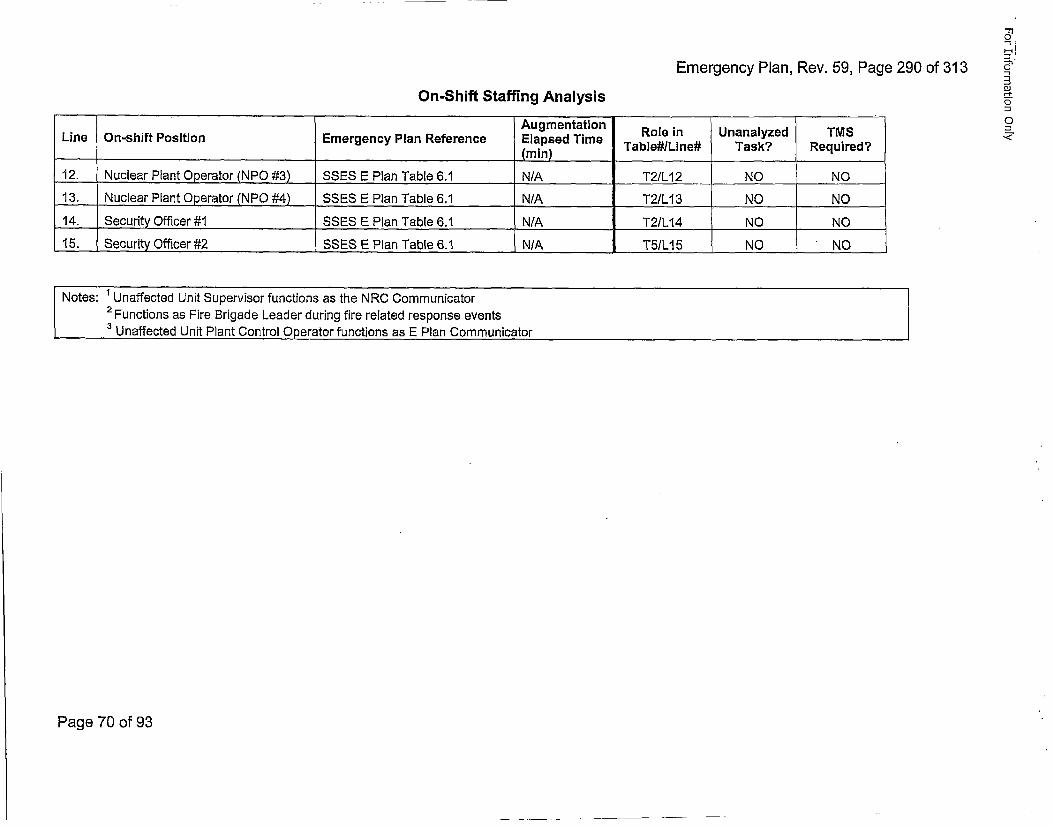
Emergency Plan, Rev. 59, Page 290 of 313
"-13
DJ
0
o
On-Shift Staffing AnalysisAugmentation Role in Unanalyzed TMS
Line On-shift Position Emergency Plan Reference Elapsed Time TbeJie ak eurd(rai) __abe#___ne# Task?___ .... _Required
12. Nucle.a.r Plant Operator (NPO #3) SSES E Plan Table 6.1 N/A T2/L12 NO NO
13. Nuclear Plant Operator (NPO #4) SSES E Plan Table 6.1 N/A T2/L13 NO NO
14. Security Officer #1 SSES E Plan Table 6.1 N/A T2/L14 NO NO15. Security Officer #2 SS ES E Plan Table 6.1 N/A T5/L15 NO ' NO
Notes: ' Unaffected Unit Supervisor functions as the NRC Communicator2Functions as Fire Brigade Leader during fire related response events3 Unaffected Unit Plant Control Operator functions as E Plan Communicator
Page 70 of 93
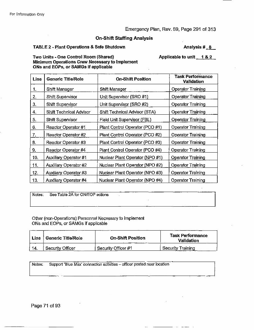
For Information Only
Emergency Plan, Rev. 59, Page 291 of 313
On-Shift Staffing Analysis
TABLE 2 - Plant Operations & Safe Shutdown Analysis # 8
Two Units - One Control Room (Shared)Minimum Operations Crew Necessary to ImplementONs and EOPs, or SAMGs if applicable
Applicable to unit 1 & 2
Task PerformanceLine Generic Title/Role On-Shift Position Vldto
1. Shift Manager Shift Manager 0perator Training
2. Shift Supervisor Unit Supervisor (SRO #1) Operator Training
3. Shift Supervisor Unit Supervisor (SRO #2) Operator Training
4. Shift Technical Advisor Shift Technical Advisor (STA) Operator Training
5. Shift Supervisor Field Unit Supervisor (FBL) Operator Training
6. Reactor Operator #1 Plant Control Operator (PCO #1) Operator Training
7. Reactor Operator #2 Plant Control Operator (PCO #2) Operator Training
8. Reactor Operator #3 Plant Control 0perator (PCO #3) 0perator Training
9. Reactor Operator #4 Plant Control Operator (PCO #4) Operator Training
10. Auxiliary Operator #1 Nuclear Plant Operator (NPO #1 ) Operator Training
11. Auxiliary Operator #2 Nuclear Plant Operator (NPO #2) Operator Training
12. Auxiliary Operator #3 Nuclear Plant Operator (NPO #3) Operator Training
13. Auxiliary Operator #4 Nuclear Plant Operator (NPO #4) Operator Training
f Notes: See Table 2A for ON/EOP actions
Other (non-Operations) Personnel Necessary to lmplementONs and EOPs, or SAMGs if applicable
SNotes: Support 'Blue Max' connection activities -. officer posted near location
Page 71 of 93
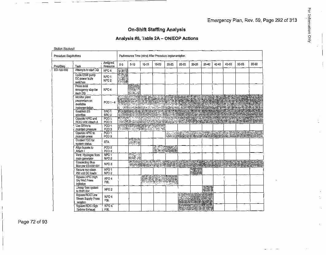
-1
Emergency Plan, Rev. 59, Page 292 of 313 -"
OJ4-,
COn-Shift Staffing Analysis
Analysis #8, Table 2A - ON/EOP Actions
Station Blrackouit
Procedure Step/Actions Perfonnance Time (mins) After Procedure Implementa~tion
Assigned 0-5 5-10 10-15 15-20 0-5 25-30 30-35 354 045 4-0 505 56
EO-100-030 Attempts to start DG NPO 4 •;t Tt,•,Cycle ESW pump NPO 1 I:,':: iDC power knife N 'P " 2 ° '" ____ ___
switches .__ ._._ _ _ _ _ _ ___ _ _ _Press local :"•emergency stop for NPOparamterson P01-4: 7 1ea h O _ _Monitor plant ''..,.,.,• - ,-.;..,#-• :• .•,.,,, ,., .," ..•,*,v
Establish ES SRO 1 :;_ •.
m a in ta in p re ssu re P 0O 3 •: .z•,. .:! - .:; : F,• ;: i,• ,• • __."-" " ___ _____-__ _-__ _
maintain press P00 3 _ '_____ • '-' ,•'';""• • ;"' ______•'•' ;• _______'••'"
Contact TOO for STA •=•:,"!,;•system status __________ ___ _____________Align busses to P002 :.•:::.:-,,• • •,'
Vent Hydrogen from NPO 1 1 -.,.•,xJ; r-main generator NPO 2 ,,___,.___' __.:_ ___,___,.__
Secure non-class NPO 1 ]250 volt DO loads NPO 2 ...-__ _ .,__ I ___I _ __.__ ._ _ _ _ _ _ _ _
Bypass HPIC HighDry Well PressInitiation
NPO 4FBL .. . .... .. •,. - . .... : ':';i,;.X'!t;•
LinemSupp tires s ste NP0IsoHationBypass ROIC Low NPO 4Steam Supply Press FBLIsolation __________ ________ _______ ________ ________
Bypass ROIC High NPO 4Turbine Exhaust - FBL -. _______ - i1~1_
Page 72 of 93
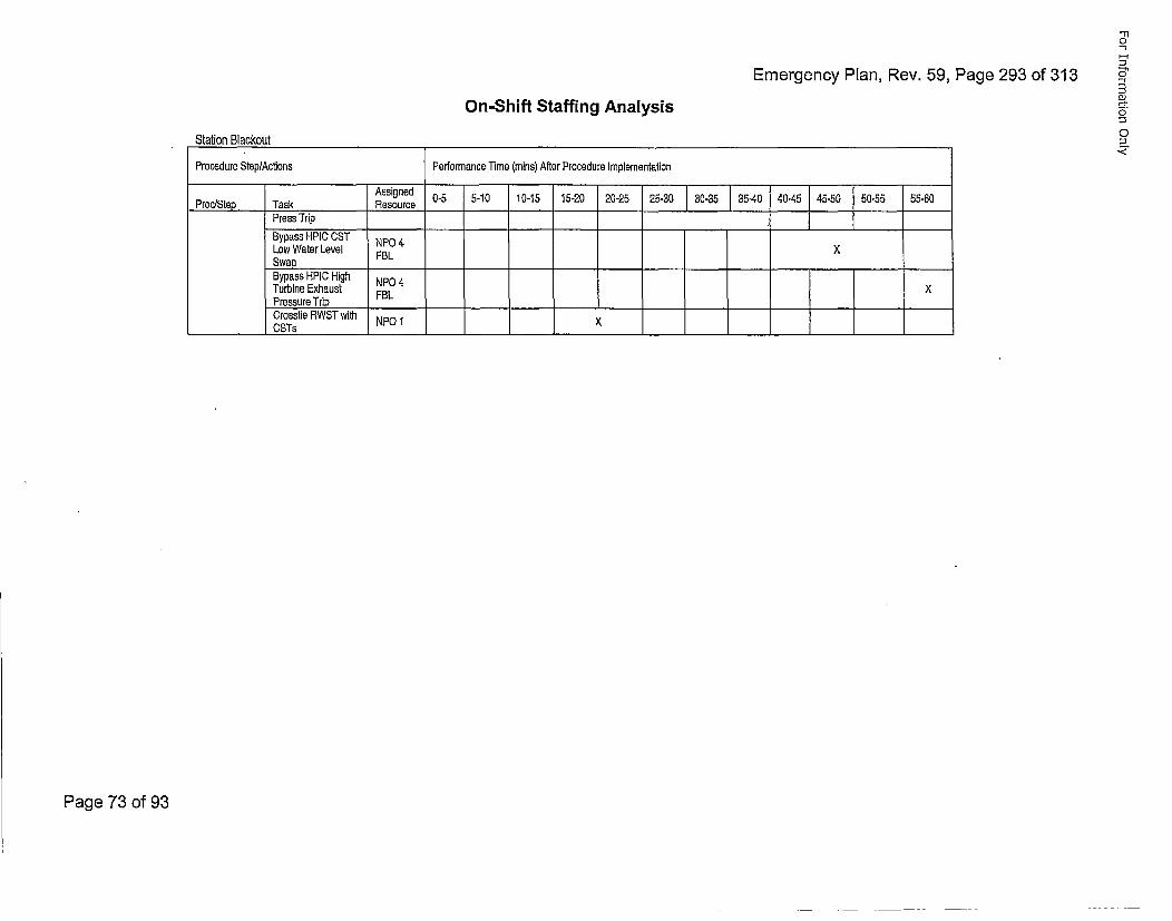
Emergency Plan, Rev. 59, Page 293 of 313
F,
~130,:
o
0
On-Shift Staffing Analysis
,Station Blackout
Procedure Step/Actions Performance Time (rains) After Procedure Implementation
PrssieTakgrie~d 5 0-5 5-10 10-15 15-20 20-25 25-~30 0-35 35A0 4045 45-50 [50-55 55-60
Bypass HPIC CST NPO 4xLow Water Level FBSwap . __..
Bypass HPIC High NPO 4Turbine Exhaust FBLPressure Trip ____________________________ _______
Crosstie RWST with NPO 1 X__________CSTs ___________ _____________ ______
Page 73 of 93

For Information Only
Emergency Plan, Rev. 59, Page 294 of 313On-Shift Staffing Analysis
TABLE 3 - Firefighting Analysis# 8
LinePerorme ByTask AnalysisLine eifoned ByControlling Method
1. N/A N/A
2. N/A N/A
3. N/A N/A
4. N/A N/A
5. N/A N/A
SNotes: No fire Brigade response required for this event.
Page 74 of 93
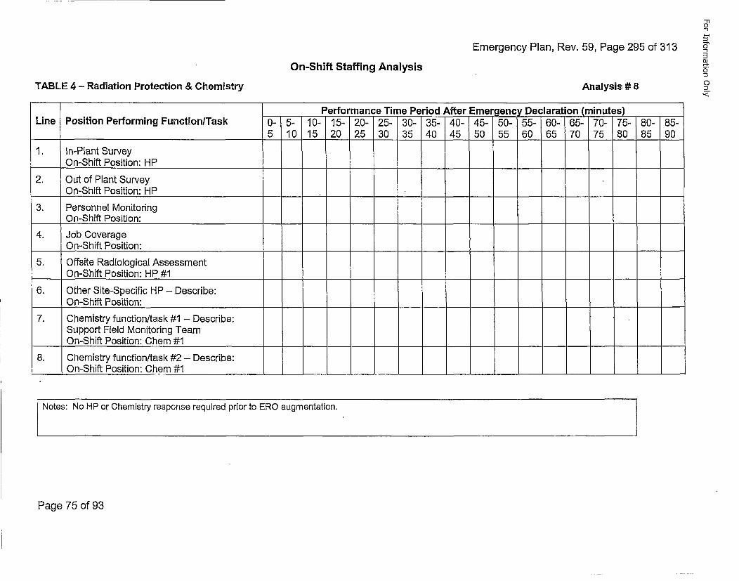
Emergency Plan, Rev. 59, Page 295 of 313
'-r"-I
0"
03
0
0
On-Shift Staffing Analysis
TABLE 4 - Radiation Protection & Chemistry Analysis # 8
Performance Time Period After Emergency Declaration (minutes)Line Position Performing Function/Task 0- 5- 10- 15- 20- 25- 30- 35- 40- 45- 50- 55- 60- 65- 70- 75- 80- 85-
5 10 15 20 25 30 35 40 45 50 55 60 65 70 75 80 85 90
1. In-Plant SurveyOn-Shift Position: HP
2. Out of Plant SurveyOn-Shift Position: HP____
3. Personnel MonitoringOn-Shift Position:
4. Job CoverageOn-Shift Position:
5. Offsite Radiological Assessment___On-Shift Position: HP #1
6. Other Site-Specific HP - Describe:On-Shift Position:
7. Chemistry function/task #1 - Describe:Support Field Monitoring Team
___On-Shift Position: Chem #1 _
8. Chemistry function/task #2 - Describe:On-ShiftPosition:_Chem_#1____ ____________ ____ __
Notes: No HP or Chemistry response required prior to ERO augmentation.
Page 75 of 93
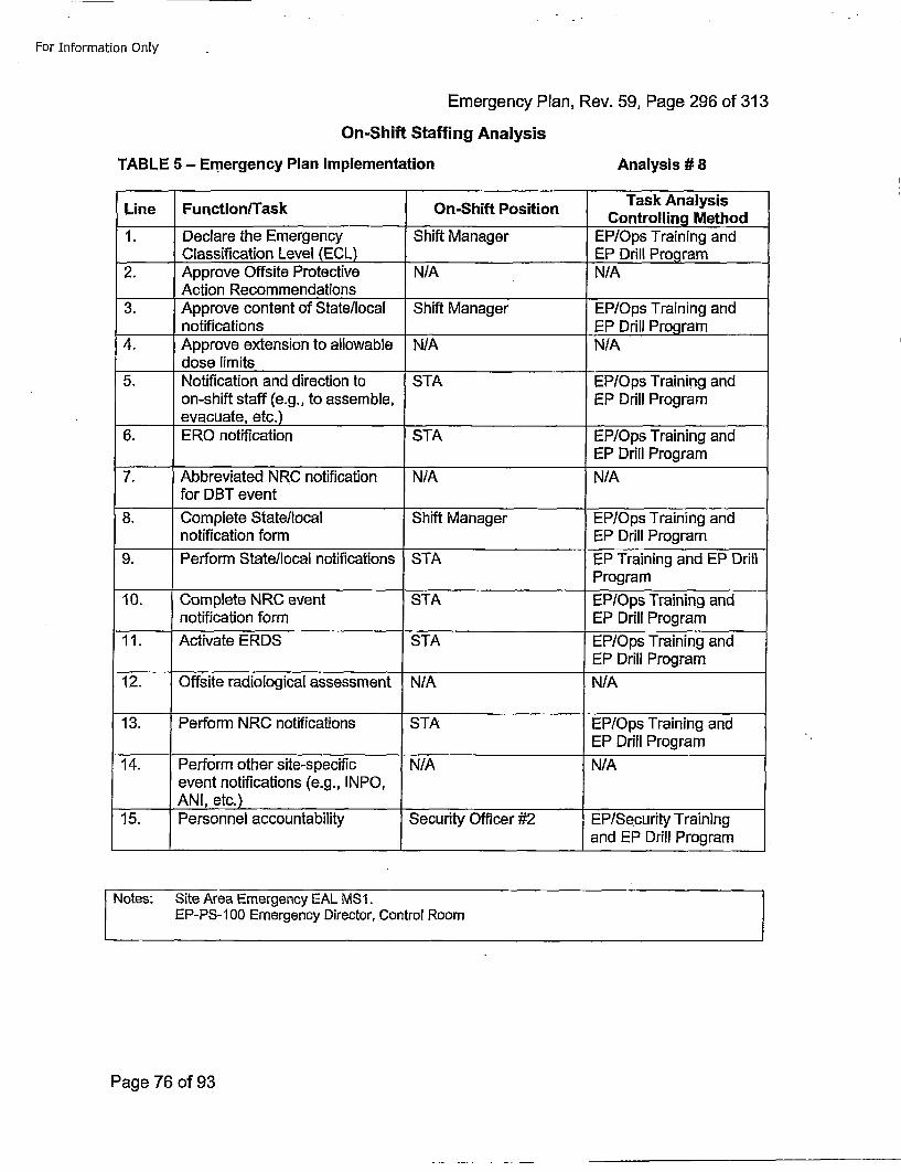
For Information Only
Emergency Plan, Rev. 59, Page 296 Of 313On-Shift Staffing Analysis
TABLE 5 - Emergency Plan Implementation Analysis # 8
Task AnalysisLine Function/Task On-Shift Position CnrligMto
1. Declare the Emergency Shift Manager EP/Ops Training andClassification Level (ECL) EP Drill Program
2. Approve Offsite Protective N/A N/A____Action Recommendations
3. Approve content of State/local Shift Manager EP/Ops Training andnotifications EP Drill Program
4. Approve extension to allowable N/A, N/Adose limits
5. Notification and direction to STA EP/Ops Training andon-shift staff (e.g., to assemble, EP Drill Programevacuate, etc.)
6. ERO notification STA EP/Ops Training andEP Drill Program
7. Abbreviated NRC notification N/A N/Afor DBT event
8. Complete State/local Shift Manager EP/Ops Training andnotification form EP Drill Program
9. Perform State/local notifications STA EP Training and EP DrillProgram
10. Complete NRC event STA EP/Ops Training andnotification form EP Drill Program
11. Activate ERDS STA EP/Ops Training andEP Drill Program
12. Offsite radiological assessment N/A N/A
13. Perform NRC notifications STA EP/Ops Training andEP Drill Program
14. Perform other site-specific N/A N/Aevent notifications (e.g., INPO,ANI, etc.) ...
15. Personnel accountability Security Officer #2 EP/Security Trainingand EP Drill Program
Notes: Site Area Emergency EAL MS1.EP-PS-I100 Emergency Director, Control Room
Page 76 of 93
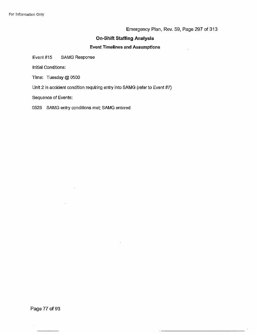
For Information Only
Emergency Plan, Rev. 59, Page 297 of 313
On-Shift Staffing Analysis
Event Timelines and Assumptions
Event #15 SAMG Response
Initial Conditions:
Time: Tuesday @ 0500
Unit 2 in accident condition requiring entry into SAMG (refer to Event #7)
Sequence of Events:
0525 SAMG entry conditions met; SAMG entered
Page 77 of 93
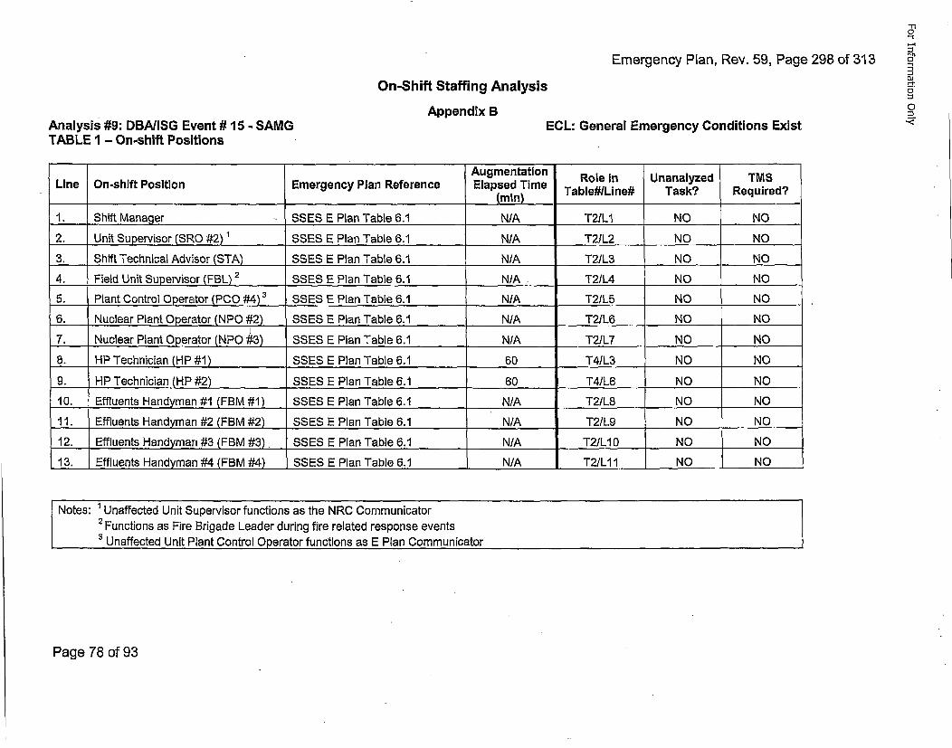
Emergency Plan, Rev. 59, Page 296 of 313
5'-5"
DiOn-Shift Staffing Analysis
Appendix B 0ECL: General Emergency Conditions ExistAnalysis #9: DBA/ISG Event # 15 - SAMGTABLE 1 - On-shift Positions
Augmentation Role in Unanalyzed TMSLine On-shift Position Emergency Plan Reference Elapsed Time TbeIie ak eurd
1. Shift Managjer SSES E Plan Table 6.1 N/A T2IL1 NO NO
2. Unit Supervisor (SRO #2) 1 SSES E Plan Table 6.1 N/A T21L2 NO NO
3. Shift Technical Advisor (STA) SSES E Plan Table 6.1 N/A T2/L3 ... NO NO
4. Field Unit Supervisor (FBL) 2 SSES E Plan Table 6.1 N/A .T2/L4 NO NO
5. Plant Control Operator (PCO #4)3 SSES E Plan Table 6.1 N/A T2/L5 NO NO
6. Nuclear Plant Operator (NPO #2) SSES E Plan Table 6.1 N/A T2/L6 NO NO
7. Nuclear Plant Operator (NPO #3) SSES E Plan Table 6.1 N/A T2/L7 NO NO
6. HP Technician (HP #1) SSES E Plan Table 6.1 60 T4/L3 NO NO
9. HP Technician (HP #2) SSES E Plan Table 6.1 60 T4/L6 NO NO
10. Effluents Handyman #1 (FBM #1) SSES E Plan Table 6.1 N/A T2/L8 NO ... NO
11. Effluents Handyman #2 (FBM #2) SSES E Plan Table 6.1 N/A T2/L9 NO NO
12. Effluents Handyman #3 (FBM #3) SSES E Plan Table 6.1 N/A T2/L10 NO NO
13. Effluents Handyman #4 (FBM #4) SSES E Plan Table 6.1 N/A T2/LII NO NO
Notes: ' Unaffected Unit Supervisor functions as the NRC Communicator2 Functions as Fire Brigade Leader during fire related response events
3 Unaffected Unit Plant Control Operator functions as E Plan Communicator
Page 78 of 93
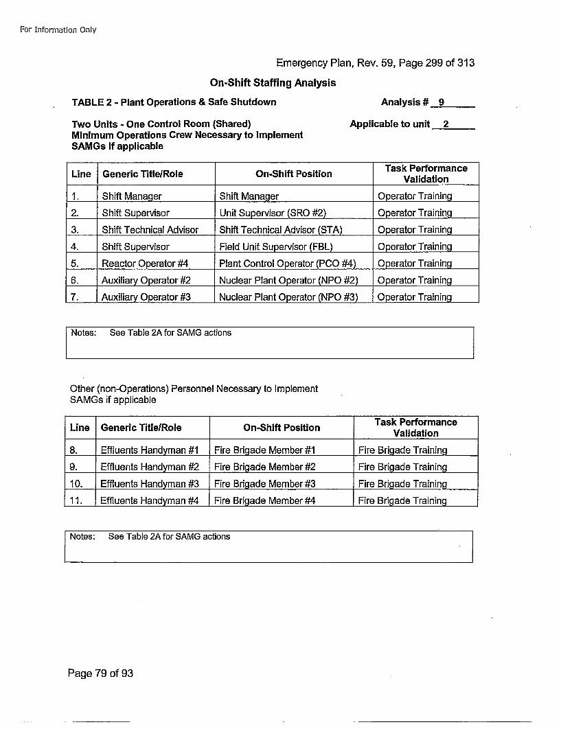
For Information Only
Emergency Plan, Rev. 59, Page 299 of 313
On-Shift Staffing Analysis
TABLE 2 - Plant Operations & Safe Shutdown Analysis # 9
Two Units - One Control Room (Shared)Minimum Operations Crew Necessary to ImplementSAMGs if applicable
Applicable to unit 2
Task PerformanceLine Generic Title/Role On-Shift Position Vldto
1. Shift Manager Shift Manager Operator Training
2. Shift Supervisor Unit Supervisor (SRO #2) Operator Training
3. Shift Technical Advisor Shift Technical Advisor (STA) Operator Training
4. Shift Supervisor Field Unit Supervisor (FBL) Operator Training
5. Reactor Operator #4 Plant Control Operator (PCO #4) Operator Training
6. Auxiliary Operator #2 Nuclear Plant Operator (NPO #2) Operator Training
7. Auxiliary Operator #3 Nuclear Plant Operator (NPO #3) Operator Training
Other (non-Operations) Personnel Necessary to ImplementSAMGs if applicable
Task PerformanceLine Generic TitleIRole On-Shift Position Vldto
8. Efluets Hndyan # FirBriadeMembr#1FireBrialdeTationin
9. Effluents Handyman #2 Fire Brigade Member #2 Fire Brigade Training
10. Effluents Handyman #3 Fire Brigade Member #3 Fire Brigade Training
11. Effluents Handyman #4 Fire Brigade Member #3 Fire Brigade Training
SNotes: See Table 2A for SAMG actions
Page 79 of 93
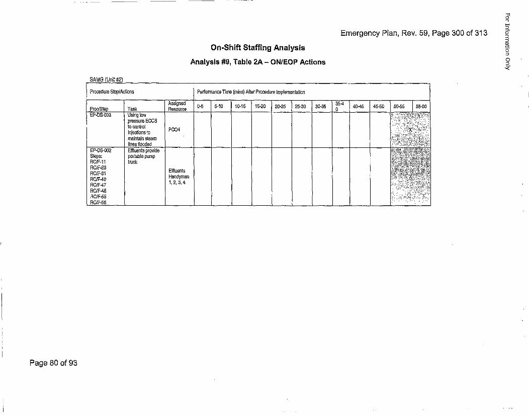
Emergency Plan, Rev. 59, Page 300 of 313
'-110
0"
DJ
0
,,
On-Shift Staffing AnalysisAnalysis #9, Table 2A - ON/EOP Actions
SAMG (Unit #2)
Procedure Step/Actions Performance Time (mains) After Procedure Implementation
ArcSe akRssirned 0-5 5-10 10-15 15-20 20-25 25-30 30-35 0 40-45 45-50 50-55 55-50
EP-DS-003 Using low • • ,'.•..'-"2-..;pressure ECOS ,L•.',• ';,• " i ;.
I~njectionsC~to to P.004 ;,.: ; !,;•"..
maintain steam •'"'" ":" ,•"-••"lines flooded "__"_"_____"__"'#
EP-DS-002 Effluents provide!,..•.'•"'"":"•';,; ,,. •""Steps: portable pump :;.-.,.x,..,.•, ,,.RO/F-1 1 truck , ,,t,,,•.. :•,,•RO/F-2I Effluents ••-";-ii'!!i':.••
RC/F-40 Handyman •.,,.........X•, •;..
RC/F-48 ... .. :.....,.• ,.,
RC/F-55
Page 80 of 93
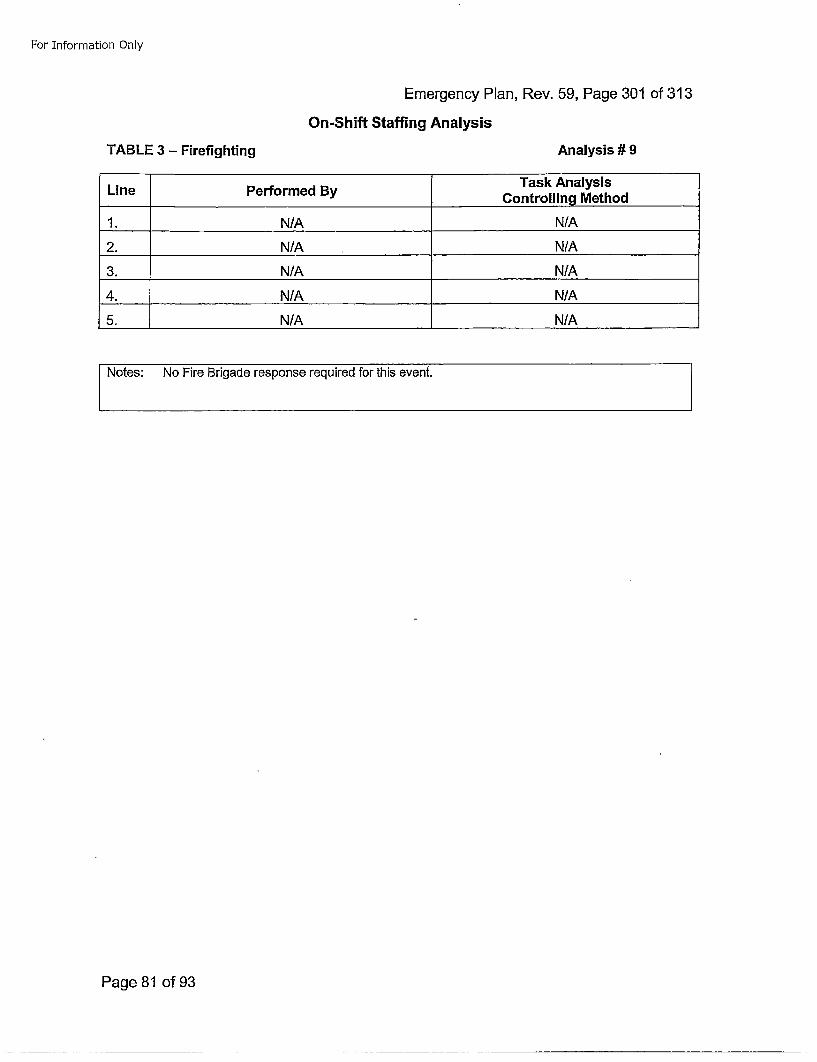
For Information Only
Emergency Plan, Rev. 59, Page 301 of 313
On-Shift Staffing Analysis
TABLE 3 - Firefighting Analysis# 9
LinePerorme ByTask AnalysisLinePerorme ByControlling Method
1. N/A N/A
2. N/A N/A
3. N/A N/A
4. N/A N/A
5. N/A N/A
Notes: No Fire Brigade response required for this event.
Page 81 of 93
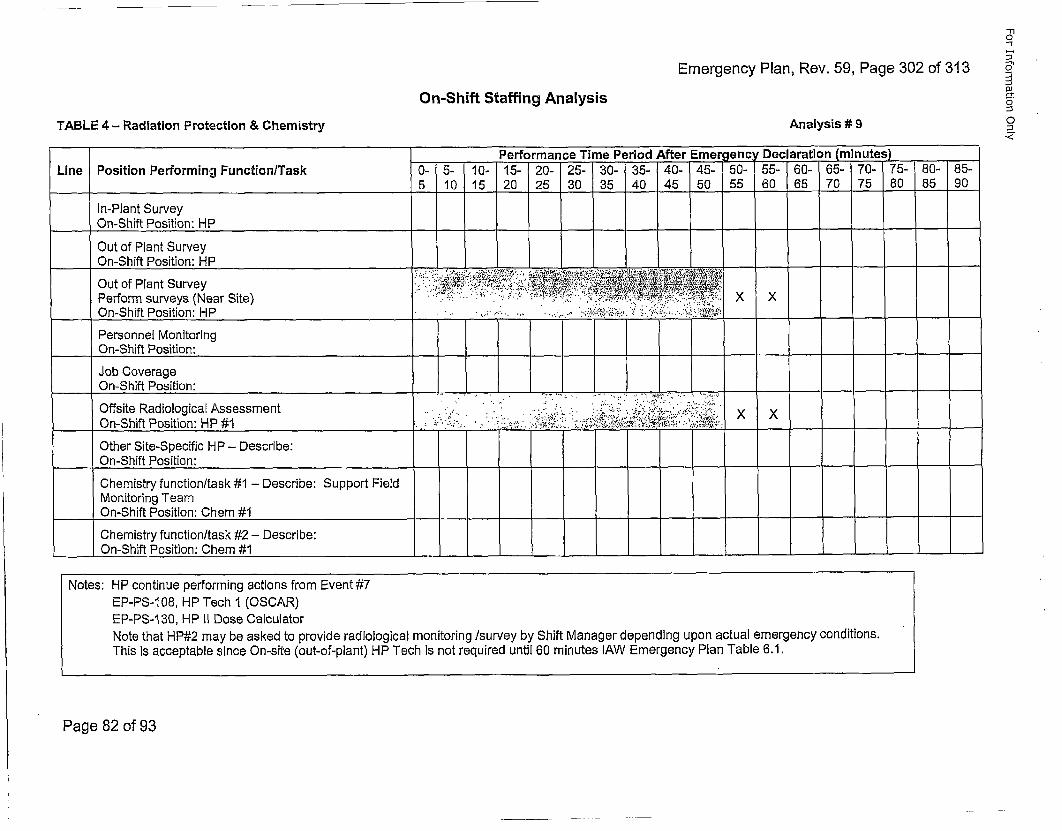
Emergency Plan, Rev. 59, Page 302 of 313
m10
5•~
0'
O
o
On-Shift Staffing Analysis
TABLE 4 - Radiation Protection & Chemistry Analysis # 9
Performance Time Period After Emergency Declaration (minutes)Line Position Performing Function/Task 0- 5- 10- 15- 20- 25- 30- 35- 40- 45- 50- 55- 60- 65- 70- 75- 80- 85-
5 10 15 20 25 30 35 40 45 50 55 60 65 70 75 80 85 90
In-Plant Survey___On-Shift Position: HP
Out of Plant SurveyOn-Shift Position: HP
Out of Plant Survey .° :.: -,:., :.•:,:*,.,•::-.,- :;;,•••.'••a.: • •;,•.!,,•'t!••:. °Perform surveys (Near Site) " ";::. .••: •/. •",!°:'°Yf '.. . •.• •':::::::•:. X X
.. O n-Shift Position:.HP -. .. ; .. .. . .'-=-; :;.••,!...:.•:.•...:......-•• •
Personnel MonitoringOn-Shift Position:
Job Coverage____On-Shift Position:
Offsite Radiological Assessment .. - .. .-... x... .. , x.-,.:.-: .''.,. , •:-.On-Shift Position: HP #1 . ,....... .•••. ..,-.• ,...•,, ,~: ,•••,.•,:,•,;•,,.•,.,••.
Other Site-Specific HP - Describe:On-Shift Position:
Chemistry function/task #1 - Describe: Support FieldMonitoring TeamOn-Shift Position: Chem #1- ---- - - -- - - -
Chemistry function/task #2 - Describe:On-Shift Position: Chem #1 - _
Notes: HP continue performing actions from Event #7EP-PS-1 08, HP Tech I (OSCAR)EP-PS-I130, HP II Dose CalculatorNote that HP#2 may be asked to provide radiological monitoring /survey by Shift Manager depending upon actual emergency conditions.This is acceptable since On-site (out-of-plant) HP Tech is not required until 60 minutes lAW Emergency Plan Table 6.1.
Page 82 of 93
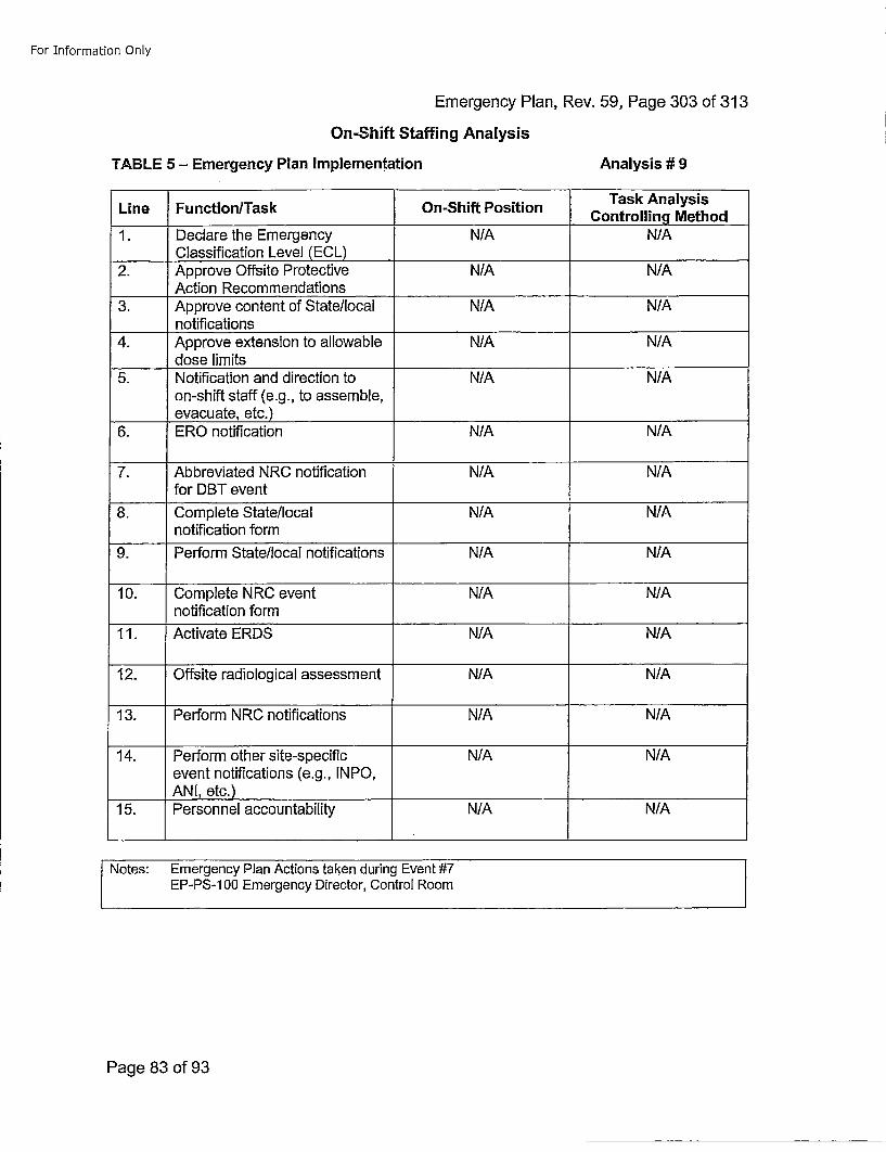
For Information Only
Emergency Plan, Rev. 59, Page 303 of 313On-Shift Staffing Analysis
TABLE 5 - Emergency Plan Implementation Analysis # 9
Line Function/Task On-Shift Position Task AnalysisControlling Method1. Declare the Emergency N/A N/A
Classification Level (ECL)2. Approve Offsite Protective N/A N/A
____Action Recommendations3. Approve content of State/local N/A N/A
notifications4. Approve extension to allowable N/A N/A
dose limits5. Notification and direction to N/A N/A
on-shift staff (e.g., to assemble,____evacuate, etc.)
6. ERO notification N/A N/A
7. Abbreviated NRC notification N/A N/Afor DBT event
8. Complete State/local N/A N/Anotification form
9. Perform State/local notifications N/A N/A
10. Complete NRC event N/A N/Anotification form
11. Activate EROS N/A N/A
12. Offsite radiological assessment N/A N/A
13. Perform N RC notifications N/A N/A
14. Perform other site-specific N/A N/Aevent notifications (e.g., INPO,AN I, etc.)
15. Personnel accountability N/A N/A
Notes: Emergency Plan Actions taken during Event #7EP-PS-1 00 Emergency Director, Control Room
Page 83 of 93
For Information Only
Emergency Plan, Rev. 59, Page 304 of 313On-Shift Staffing Analysis
Appendix CPhase Ill Time Motion Study Analysis Results
Page 84 of 93
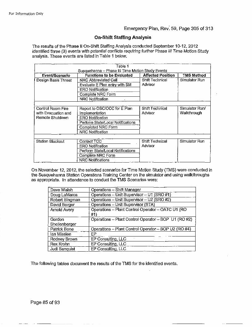
For Information Only
Emergency Plan, Rev. 59, Page 305 of 313
On-Shift Staffing Analysis
The results of the Phase II On-Shift Staffing Analysis conducted September 10-12, 2012identified three (3) events with potential conflicts requiring further Phase Ill Time Motion Studyanalysis. These events are listed in Table 1 below.
Table 1_________________Susguehanna - Phase Ili Time Motion Study Events ________
EventlScenario Functions to be Evaluated Affected Position TMS MethodDesign Basis Threat NRC Abbreviated Call Shift Technical 4Simulator Run
Evaluate EPlan entry with SM AdvisorERO NotificationComplete NRC Form
_________________ NRC Notification _________ _______
Control Room Fire Report to OSC/OCC for E Plan Shift Technical Simulator Runlwith Evacuation and Implementation Advisor WalkthroughRemote Shutdown ERO Notification
Perform State/Local NotificationsCompleted NRC Form
_________________ NRC Notification_________ ________
Station Blackout Contact TCC Shift Technical Simulator RunERO Notification AdvisorPerform State/Local NotificationsComplete NRC FormNRC Notifications_________
On November 12, 2012, the selected scenarios for Time Motion Study (TMS) were conducted inthe Susquehanna Station Operations Training Center on the simulator and using walkthroughsas appropriate. In attendance to conduct the TMS Scenarios were:
Dave Walsh Operations - Shift Manager_Doug LaMarca Operations - Unit Supervisor- U1 (SRO #1)_Robert Bingman Operations - Unit Supervisor - U2 (SRO #2)David Borger Operations - Unit Supervisor (STA)Arnold Avery Operations - Plant Control Operator- OATC UI (RO
#1)-Gordon Operations - Plant Control Operator- BOP U1 (RO #2)ShellenbergerPatrick Bone Operations - Plant Control Operator - BOP U2 (RO #4)lan Missien EPRodney Brown EP Consulting, LLCRex Krohn EP Consulting, LLCJudi San uist EP Consulting, LLC
The following tables document the results of the TMS for the identified events.
Page 85 of 93
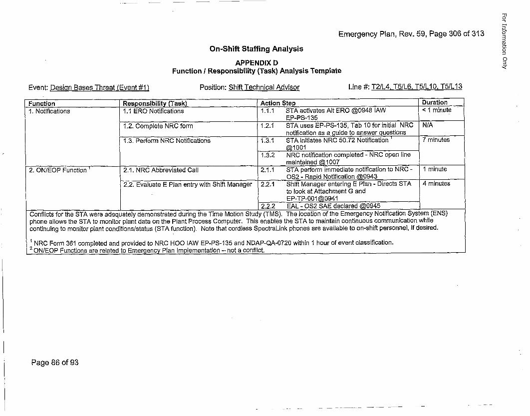
Emergency Plan, Rev. 59, Page 306 of 313On-Shift Staffing Analysis
APPENDIX DFunction / Responsibility (Task) Analysis Template
-i
0"
C
Event: Desigqn Bases Threat (Event #1 ) Position: Shift Technical Advisor Line #: T2/L4. T5/L6, T5/L10, T5/L13
Function Responsibility (Task). Action Step Duration1. Notifications 1.1 ERO Notifications 1.1.1 STA activates Alt ERO @0948 lAW <1I minuteEP-PS-1 35
1.2. Complete NRC form 1.2.1 STA uses EP-PS-135, Tab 10 for initial NRC N/Anotification as a guide to answer questions
1.3. Perform NRC Notifications 1.3.1 STA initiates NRC 50.72 Notification 1 7 minutes
1.3,2 NRC notification completed - NRC open line
2. ON/EOP Function 2.1. NRC Abbreviated Call 2.1.1 STA perform immediate notification to NRC - '1 minute0S2 - Rapid Notification @0943 ______
2.2. Evaluate E Plan entry with Shift Manager 2.2,1 Shift Manager entering E Plan - Directs STA 4 minutesto look at Attachment G andEP-TP-O01 @0941
___________________________________________________2.2.2 EAL - 0S2 SAE declared @0945 ______
Conflicts for the STA were adequately demonstrated during the Time Motion Study (TMS), The location or tne e-mergency I'oEITcauion •ystem [t-i,•)phone allows the STA to monitor plant data on the Plant Process Computer. This enables the STA to maintain continuous communication whilecontinuing to monitor plant conditions/status (STA function). Note that cordless SpectraLink phones are available to on-shift personnel, if desired.
SNRC Form 361 completed and provided to NRC HOO lAW EP-PS-135 and NDAP-QA-0720 within 1 hour of event classification.2 0N/EOP Functions are related to Emeraencv Plan Implementation - not a conflict.
Page 86 of 93
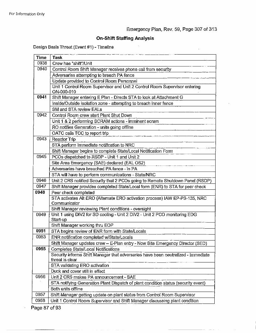
For Information Only
Emergency Plan, Rev. 59, Page 307 of 313
On-Shift Staffing Analysis
Design Basis Threat (Event #1) - Timeline
Time Task0938 Crew has "shift"/Unit0940 Control Room Shift Manager receives phone call from security
Adversaries attempting to breach PA fenceUpdate provided to Control Room PersonnelUnit 1 Control Room Supervisor and Unit 2 Control Room Supervisor enteringON-000-O1 0
0941 Shift Manager entering E Plan - Directs STA to look at Attachment GInside/Outside isolation zone - attempting to breach inner fenceSM and STA review EALs
0942 Control Room crew start Plant Shut DownUnit 1 & 2 performing SCRAM actions - imminent scramRO notifies Generation - units going offline
____OATC calls TCC to report trip0943 Reactor Trip
STA perform immediate notification to NRCShift Manager begins to complete State/Local Notification Form
0945 PCOs dispatched to RSDP -Unit 1 and Unit 2Site Area Emergency (SAE) declared (EAL OS2)Adversaries have breached PA fence - in PASTA will have to perform communications - State/NRC
0946 Unit 2 CRS notified Security that 2 PCOs going to Remote Shutdown Panel (RSDP)0947 Shift Manager provides completed State/Local form (ENR) to STA for peer check
0948 Peer check completedSTA activates Alt ERe (Alternate ERe activation process) JAW EP-PS-1 35, NRCCommunicatorShift Manager reviewing Plant conditions - oversight
0949 Unit 1 using DIV2 for SD cooling - Unit 2 DIV2 - Unit 2 PCO monitoring EDGStart-upShift Manager working thru EOP
0951 STA begins review of ENR form with State/Locals0953 ENR notification completed w/State/Locals
Shift Manager updates crew - E-Plan entry - Now Site Emergency Director (SED)0955 Completes State/Local Notifications
Security informs Shift Manager that adversaries have been neutralized - immediatethreat is clearSTA validating ERe activationDuck and cover still in effect
0956 Unit 2 CRS makes PA announcement - SAESTA notifying Generation Plant Dispatch of plant condition status (security event)Both units offline
0957 Shift Manager getting update on plant status from Control Room Supervisor0958 Unit I Control Room Supervisor and Shift Manager discussing plant condition
Page 87 of 93
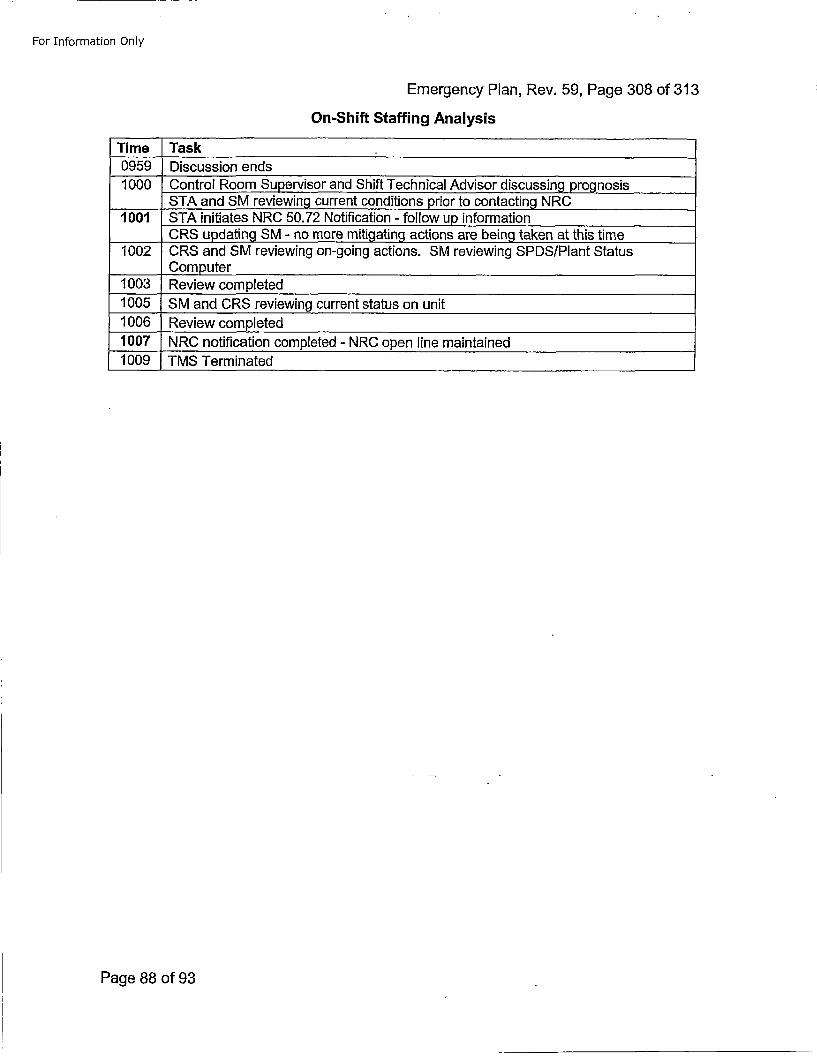
For Information Only
Emergency Plan, Rev. 59, Page 308 of 313On-Shift Staffing Analysis
Time Task0959 Discussion ends1000 Control Room Supervisor and Shift Technical Advisor discussing prognosis
STA and SM reviewing current conditions prior to contacting NRC1001 STA initiates NRC 50.72 Notification - follow up information
CR5 updating SM - no more mitigating actions are being taken at this time1002 CRS and SM reviewing on-going actions. SM reviewing SPDS/Plant Status
Computer1003 Review completed1005 SM and CRS reviewing current status on unit1006 Review completed1007 NRC notification completed - NRC open line maintained1009 TMS Terminated
Page 88 of 93
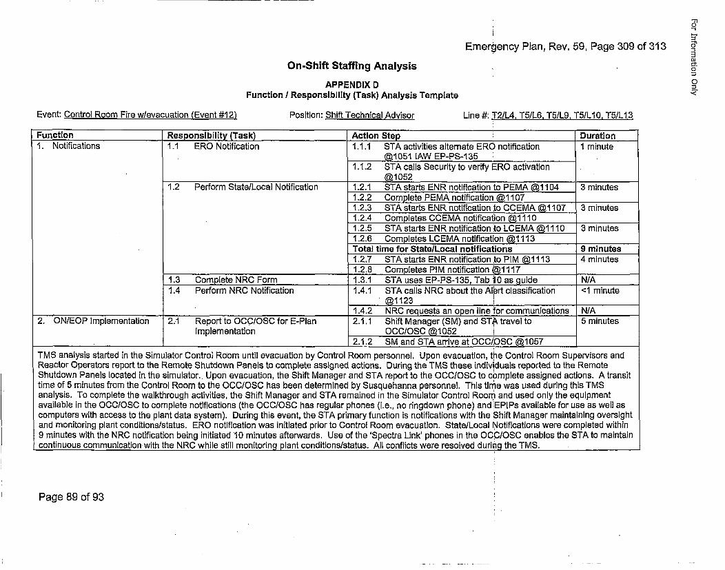
Emergency Plan, Rev. 59, Page 309 of 313
-TI
oJ
4-'
0-t
0On-Shift Staffing Analysis
APPENDIX DFunction / Responsibility (Task) Analysis Template
Event: Control Room Fire w/evacuation (Event #1 2) Position: Shift Technical Advisor Line #: T2/L4, T5/L6. T5/L9.9 T5/L10. T5/L13
Function Responsibility (Task) Action Step Duration1. Notifications 1.1 ERG Notification 1.1.1 STA activities alternate ERO notification 1 minute
@1051 lAW EP-PS-1351.1.2 STA calls Security to verify ERG activation
@1052 ______
1.2 Perform State/Local Notification 1.2.1 STA starts ENR notification ito PEMA @1104 3 minutes1.2.2 Complete PEMA notification' @11071.2.3 STA starts ENR notification ;to CCEMA @1107 3 minutes1.2.4 Completes CCEMA notification @1110 _____
1.2.5 STA starts ENR notification ito LCEMA @1110 3 minutes1.2.6 Completes LOEMA notification @1113Total time for State/Local notifications 9 minutes1,2.7 STA starts ENR notification [to PIM @1113 4 minutes
______________________________ 1.2.8 Completes PIM notification @1117 ______
1.3 Complete NRC Form . 1.3.1 STA uses EP-PS-1 35, Tab 10 as guide N/A1.4 Perform NRC Notification 1.4.1 STA calls NRC about the Alert classification <1 minute
@1123 ______1.4.2 NRC requests an open line for communications N/A
2.' ON/EOP Implementation 2.1 Report to OCCIOSC for E-Plan 2.1.1 Shift Manager (SM) and STA travel to 5 minutesImplementation OCC/OSC @1052
.. 2.1.2 SM and STA arrive at OCC/OSC @1057 _____
TMS analysis started in the Simulator Control Room until evacuation by Control Room personnel. Upon evacuation, the Control Room Supervisors andReactor Operators report to the Remote Shutdown Panels to complete assigned actions. During the TMS these individuals reported to the RemoteShutdown Panels located in the simulator.. Upon evacuation, the Shift Manager and STA report to the OCC/OSC to complete assigned actions. A transittime of 5 minutes from the Control Room to the OCC/OSC has been determined by Susquehanna personnel. This tingie was used during this TMSanalysis. To complete the walkthrough activities, the Shift Manager and STA remained in the Simulator Control Room and used only the equipmentavailable in the OCC/OSC to complete notifications (the OCC/OSC has regular phones (i.e., no ringdown phone) and ]EPIPs available for use as well ascomputers with access to the plant data system). During this event, the STA primary function is notifications with the Shift Manager maintaining oversightand monitoring plant conditions/status. ERO notification was initiated prior to Control Room evacuation. State/Local Notifications were completed within9 minutes with the NRC notification being initiated 10 minutes afterwards. Use of the 'Spectra Link' phones in the OC.C/OSC enables the STA to maintaincontinuous communicationwith the NRC while still monitoring plant conditions/status. All conflicts were resolved during the TMS.
Page 89 of 93
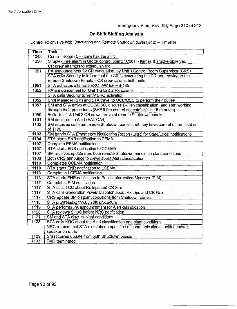
For Information Only
Emergency Plan, Rev. 59, Page 310 of 313
On-Shift Staffing Analysis
Control Room Fire with Evacuation and Remote Shutdown (Event. #12) -Timeline
Time Task1048 Control Room (CR) crew has the shift1050 Simplex Fire alarm in CR on control board 1 C601 - flames & smoke observed
____CR crew attempts to extinguish fire1051 PA announcement for CR evacuation, by Unit 1 Control Room Supervisor (CRS)
STA calls Security to inform that the CR is evacuating the CR and moving to theremote Shutdown Panels - CR crew scrams both units
1051 STA activates alternate ERO lAW EP-PS-1 351052 PA announcement for Unit I & Unit 2 Rx scrams
STA calls Security to verify ERO activation1052 Shift Manager (SM) and STA travel to OCCIOSC to perform their duties1057 SM and STA arrive at OCC/OSC, discuss E-Plan classification, and start working
through their procedures (SAE if fire control not establish in 15 minutes)1059 Both Unit 1 & Unit 2 CR crews arrive at remote Shutdown panels1101 S M declares an Alert (EAL OA4)1102 SM receives call from remote Shutdown panels that they have control of the plant as
of 11001102 SM hands STA Emergency Notification Report (ENR) for State/Local notifications1104 STA starts ENR notification to PEMA1107 Complete PEMA notification1107 STA starts ENR notification to CCEMA1107 SM receives update from both remote Shutdown panels on plant conditions1108 Both CRS announce to crews about Alert classification1110 Completes CCEMA notification1110 STA starts ENR notification to LCEMA1113 Completes LCEMA notification1113 STA starts ENR notification to Public Information Manager (PIM)1117 Completes PIM notification1117 STA calls TCC about Rx trips and CR Fire1117 STA calls Generation Power Dispatch about Rx tdips and CR Fire1117 CRS update SM on plant conditions from Shutdown panels1118 STA progressing through his procedure1119 STA performs PA announcement for Alert classification1 120 STA reviews SPDS before NRC notification1121 SM and STA discuss plant conditions1123 STA calls NRC about the Alert classification and plant conditions
NRC request that STA maintain an open line of communications - with headset,______speaker on mute
1129 SM receives update from both Shutdown panels1133 TMS terminated
Page 90 of 93
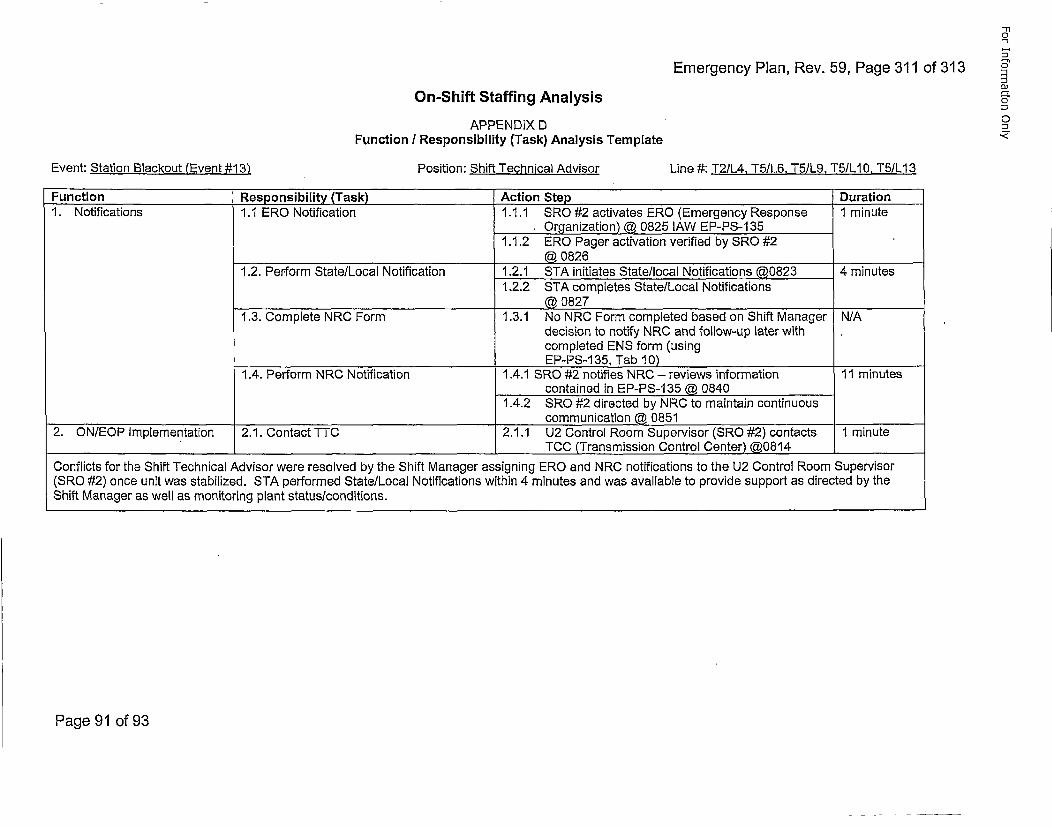
Emergency Plan, Rev. 59, Page 311 of 313
-no
0"
oJ
"1
o
On-Shift Staffing AnalysisAPPENDIX D
Function I Responsibility (Task) Analysis Template
Event: Station Blackout (Event #13') Position: Shift Technical Advisor Line #: T2/L4. T5/L6. T5/L9, T5/L10, T5/L13
Function Responsibility (Task) Action Step Duration1. Notifications 1.1 ERO Notification 1.1.1 SRO #2 activates ERO (Emergency Response 1 minuteOrganization) @ 0825 lAW EP-PS-135
1.1.2 ERO Pager activation verified by SRO #2@ 0826
1.2. Perform State/Local Notification 1.2.1 STA initiates State/local Notifications @0823 4 minutes1,2.2 STA completes State/Local Notifications
@ 08271.3. Complete NRC Form 1.3.1 No NRC Form completed based on Shift Manager N/A
decision to notify NRC and follow-up later withcompleted ENS form (using
___________________________EP-PS-1 35, Tab 10)1.4. Perform NRC Notification 1.4.1 SRO #2 notifies NRC - reviews information 11 minutes
contained in EP-PS-135 @ 08401.4.2 SRO #2 directed by NRC to maintain continuous
communication @ 08512. ONIEOP Implementation 2.1. Contact TTC 2.1.1 U2 Control Room Supervisor (SRO #2) contacts 1 minute
TCC (Transmission Control Center) @0814
Conflicts for the Shift Technical Advisor were resolved by the Shift Manager assigning ERO and NRC notifications to the U2 Control Room Supervisor(SRO #2) once unit was stabilized. STA performed State/Local Notifications within 4 minutes and was available to provide support as directed by theShift Manager as well as monitoring plant status/conditions.
Page 91 of 93
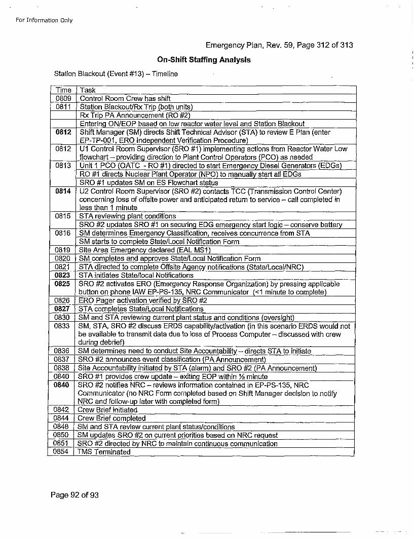
For Information Only
Emergency Plan, Rev. 59, Page 312 of 313
On-Shift Staffing Analysis
Station Blackout (Event #13) - Timeline
Time Task0809 Control Room Crew has shift0811 Station Blackout/Rx Trip (both units)
Rx Trip PA Announcement (RO #2)Entering ON/EOP based on low reactor water level and Station Blackout
0812 Shift Manager (SM) directs Shift Technical Advisor (STA) to review E Plan (enterEP-TP-001, ERO Independent Verification Procedure)
0812 U1 Control Room Supervisor (SRO #1) implementing actions from Reactor Water Low____flowchart - providing direction to Plant Control Operators (PCO) as needed
0813 Unit 1 PCO (OATC - RO #1) directed to start Emergency Diesel Generators (EDGs)RO #1 directs Nuclear Plant Operator (NPO) to manually start all EDGsSRO #1 updates SM on ES Flowchart status
0814 U2 Control Room Supervisor (SRO #2) contacts TCC (Transmission Control Center)concerning loss of offsite power and anticipated return to service - call completed in
____less than 1 minute0815 STA reviewing plant conditions
SRO #2 updates SRO #1 on securing FDG emergency start logic - conserve battery0816 SM determines Emergency Classification, receives concurrence from STA
SM starts to complete State/Local Notification Form0819 Site Area Emergency declared (EAL MS1)0820 SM completes and approves State/Local Notification Form0821 STA directed to complete Offsite Agency notifications (State/Local/NRC)0823 STA initiates State/local Notifications0825 SRO #2 activates ERO (Emergency Response Organization) by pressing applicable
button on phone lAW EP-PS-135, NRC Communicator (<1 minute to complete)0826 ERO Pager activation verified by SRO #20827 STA completes State/Local Notifications0830 SM and STA reviewing current plant status and conditions (oversight)0833 SM, STA, SRO #2 discuss ERDS capability/activation (in this scenario ERDS would not
be available to transmit data due to loss of Process Computer - discussed with crewduring debrief)
0836 SM determines need to conduct Site Accountability - directs STA to initiate0837 SRO #2 announces event classification (PA Announcement)0838 Site Accountability initiated by STA (alarm) and SRO #2 (PA Announcement)0840 SRO #1 provides crew update - exiting EOP within 1/ minute0840 SRO #2 notifies NRC - reviews information contained in EP-PS-1 35, NRC
08542-TMewTermefinitated
Page 92 of 93
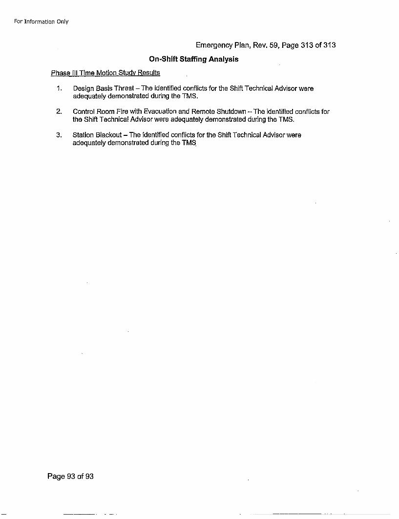
For Information Only
Emergency Plan, Rev. 59, Page 313 of 313On-Shift Staffing Analysis
Phase Ill Time Motion Study Results
1. Design Basis Threat - The identified conflicts for the Shift Technical Advisor wereadequately demonstrated during the TMS.
2. Control Room Fire with Evacuation and Remote Shutdown - The identified conflicts forthe Shift Technical Advisor were adequately demonstrated during the TMS.
3. Station Blackout - The identified conflicts for the Shift Technical Advisor wereadequately demonstrated during the TMS
Page 93 of 93
Attachment 3 to PLA-743910 CFR 50.54(q) Screens and Evaluations
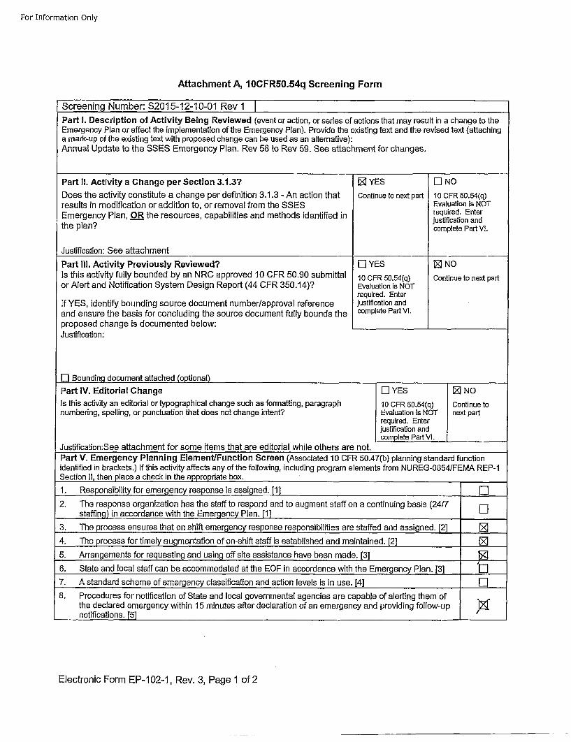
For Information Only
Attachment A, 10CFRf0.54q Screening Form
Screening Number: $2015-12-10-01 Rev 1Part I. Description of Activity Being Reviewed (event or action, or series of actions that may result in a change to theEmergency Plan or affect the implementation of the Emergency Plan). Provide the existing text and the revised text (attachinga mark-up of the existing text with proposed change can be used as an alternative):Annual Update to the SSES Emergency Plan. Rev 58 to Rev 59. See attachment for changes.
Part II. Activity a Change per Section 3.1.3? [] YES LI NODoes the activity constitute a change per definition 3.1.3 - An action that Continue to next part 10 CFR 50.54(q)results in modification or addition to, or removal from the SSES Evaluation is NOTEmergency Plan, OR the resources, capabilities and methods identified in required. Enter
the lanjustification andthe lancomplete Part VI.
Justification: See attachment
Part II1. Activity Previously Reviewed? LI YES []NOIs this activity fully bounded by an NRC approved 10 CFR 50.90 submittal 10 CFR 50.54(q) Continue to next partor Alert and Notification System Design Report (44 CFR 350.14)? Evaluation is NOT
required. EnterIf YES, identify bounding source document number/approval reference justification andand ensure the basis for concluding the source document fully bounds the complete Part Vl.proposed change is documented below: ________________
Justification:
El Bounding document attached (optional)_______Part IV. Editorial Change L] YES []NO
Is this activity an editorial or typographical change such as formatting, paragraph 10 CFR 50.54(q) Continue tonumbering, spelling, or punctuation that does not change intent? Evaluation is NOT next part
required. Enterjustification andcomplete Part VI. ______
Justification:See attachment for some items that are editorial while others are not.
Part V. Emergency Planning Element/Function Screen (Associated 10 CFR 50.47(b) planning standard functionidentified in brackets.) If this activity affects any of the following, including program elements from NUREG-0654/FEMA REP-iSection 11, then place a check in the appropriate box.
1. Responsibility for emergency response is assigned. 11] ______
2. The response organization has the staff to respond and to augment staff on a continuing basis (24/7staffing) in accordance with the Emergency Plan. [1] [
3. The process ensures that on shift emergency response responsibilities are staffed and assigned. [2] ______
4. The process for timely augmentation of on-shift staff is established and maintained. [2] [
5. Arrangements for requesting and using off site assistance have been made. [3]
6. State and local staff can be accommodated at the EOF in accordance with the Emergency Plan. [3] L[77. A standard scheme of emergency classification and action levels is in use. [41 ______
8. Procedures for notification of State and local governmental agencies are capable of alerting them ofthe declared emergency within 15 minutes after declaration of an emergency and providing follow-upnotifications. F51
Electronic Form EP-1 02-1, Rev. 3, Page 1 of 2
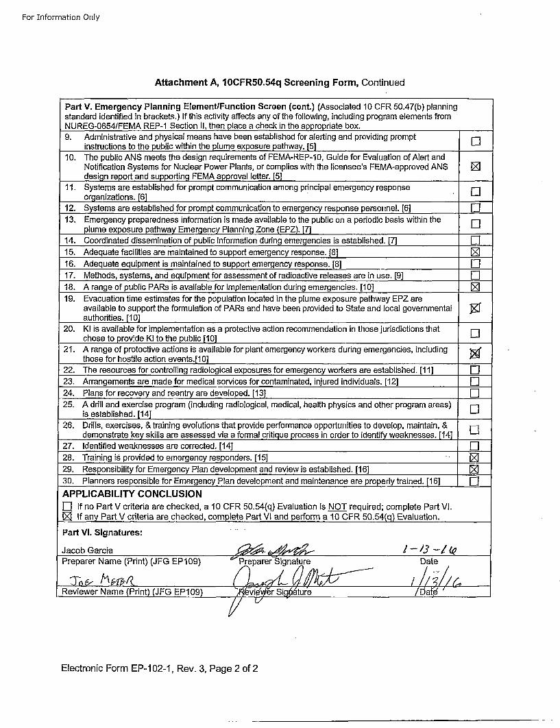
For Information Only
Attachment A, 10CFR50.54q Screening Form, Continued
Part V. Emergency Planning Element/Function Screen (cont.) (Associated 10 CFR 50.47(b) planningstandard identified in brackets.) If this activity affects any of the following, including program elements fromNUREG-0654/FEMA REP-I Section II. then olace a check in the aoorooriate box.9. Administrative and physical means have been established for alerting and providing prompt
instructions to the public within the plume exposure pathway. [5] [
10. The public ANS meets the design requirements of FEMA-REP-10, Guide for Evaluation of Alert andNotification Systems for Nuclear Power Plants, or complies with the licensee's FEMA-approved ANS []design report and supporting FEMA approval letter. [5]
11. Systems are established for prompt communication among principal emergency response Liorganizations. [6]
12. Systems are established for prompt communication to emergency response personnel. [6] LII13. Emergency preparedness information is made available to the public on a periodic basis within the [
plume exposure pathway Emergency Planning Zone (EPZ). [7]14. Coordinated dissemination of public information during emergencies is established. [7] El15. Adequate facilities are maintained to supp~ort emergency response. [8]1[
16. Adequate equipment is maintained to support emergency response. [8] El17. Methods, systems, and equipment for assessment of radioactive releases are in use. [9] El18. A range of public PARs is available for implementation during emergencies. [10] [
19. Evacuation time estimates for the population located in the plume exposure pathway EPZ areavailable to support the formulation of PARs and have been provided to State and local governmental ~authorities. [10]
20. KI is available for implementation as a protective action recommendation in those jurisdictions that Echose to provide KI to the public [10] [
21. A range of protective actions is available for plant emergency workers during emergencies, includingthose for hostile action events.[10]
22. The resources for controlling radiological exposures for emergency workers are established. [11] El23. Arrangements are made for medical services for contaminated, injured individuals. [12] El24. Plans for recovery and reentry are developed. [13] El25. A drill and exercise program (including radiological, medical, health physics and other program areas) E
is established. [14] [
26. Drills, exercises, & training evolutions that provide performance opportunities to develop, maintain, & [demonstrate key skills are assessed via a formal critique process in order to identify weaknesses. [14] E
27. Identified weaknesses are corrected. [14] El28. Training is provided to emergency responders. [15]1 [29. Responsibility for Emergency Plan development and review is established. [16] [30. Planners responsible for Emergency Plan development and maintenance are properly trained. [16] ElAPPLICABILITY CONCLUSIONEl If no Part V criteria are checked, a 10 CFR 50.54(q) Evaluation is NOT required; complete Part VI.[] If any Part V criteria are checked, complete Part VI and perform a 10 CFR 50.54(q) Evaluation.
Part VI. Signatures:
Jacob Garcia ,J: . €•• / -/3 -1k'Preparer Name (Print) (JFG EP109) c'Preparer•Signature Date
Reviewer Name (Print) JFG 1EP109) ,4vie' er Sig )ture /Da{; -
Electronic Form EP-1 02-1, Rev. 3, Page 2 of 2
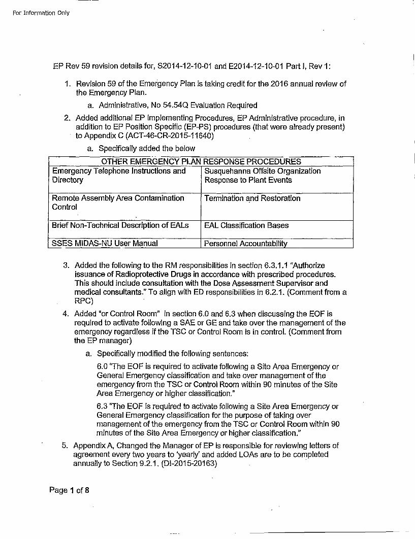
For Information Only
EP Rev 59 revision details for, S2014-12-10-0t and E2014-12-10-01 Part I, Rev 1:
1. Revision 59 of the Emergency Plan is taking credit for the 2016 annual review ofthe Emergency Plan.
a. Administrative, No 54.54Q Evaluation Required
2. Added additional EP Implementing Procedures, EP Administrative procedure, inaddition to EP Position Specific (EP-PS) procedures (that were already present)to Appendix C (ACT-46-CR-2015-11640)
a. Specifically added the below
OTHER EMERGENCY PLAN RESPONSE PROCEDURESEmergency Telephone Instructions and Susquehanna Offsite OrganizationDirectory Response to Plant Events
Remote Assembly Area Contamination Termination and RestorationControl
Brief Non-Technical Description of EALs EAL Classification Bases
SSES MIDAS-NU User Manual Personnel Accountability
3. Added the following to the RM responsibilities in section 6.3.1.1 "Authorizeissuance of Radioprotective Drugs in accordance with prescribed procedures.This should include consultation with the Dose Assessment Supervisor andmedical consultants." To align with ED responsibilities in 6.2.1. (Comment from aRPC)
4. Added "or Control Room" in section 6.0 and 6.3 when discussing the EOF isrequired to activate following a SAE or GE and take over the management of theemergency regardless if the TSC or Control Room is in control. (Comment fromthe EP manager)
a. Specifically modified the following sentences:
6.0 "The EOF is required to activate following a Site Area Emergency orGeneral Emergency classification and take over management of theemergency from the TSC or Control Room within 90 minutes of the SiteArea Emergency or higher classification."
6.3 "The EOF is required to activate following a Site Area Emergency orGeneral Emergency classification for the purpose of taking overmanagement of the emergency from the TSC or Control Room within 90minutes of the Site Area Emergency or higher classification."
5. Appendix A, Changed the Manager of EP is responsible for reviewing letters ofagreement every two years to 'yearly' and added LOAs are to be completedannually to Section 9.2.1. (DI-201 5-20163)
Page 1 of 8
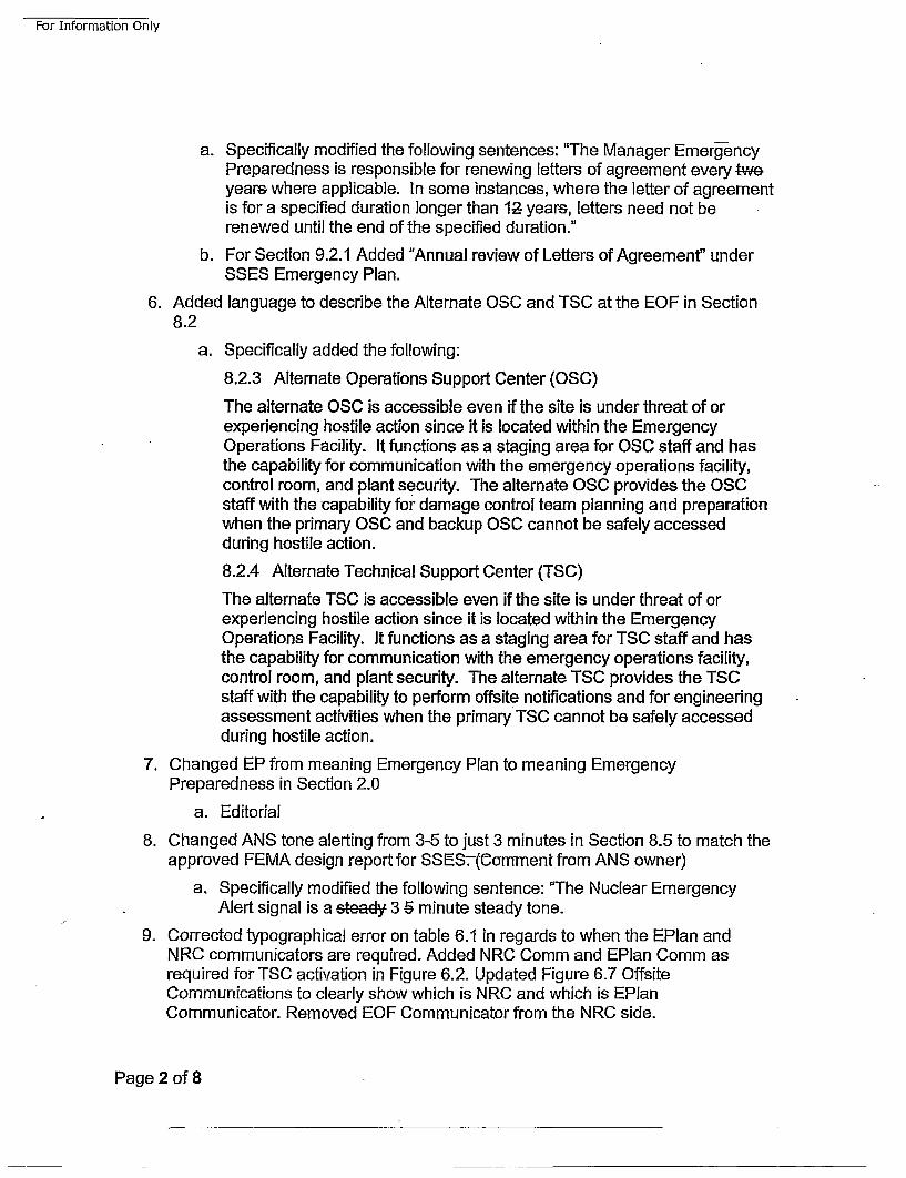
For Information Only
a. Specifically modified the following sentences: "The Manager Emerg-encyPreparedness is responsible for renewing letters of agreement every tweyears where applicable. In some instances, where the letter of agreementis for a specified duration longer than 12- years, letters need not berenewed until the end of the specified duration."
b. For Section 9.2.1 Added "Annual review of Letters of Agreement" underSSES Emergency Plan.
6. Added language to describe the Alternate OSC and TSC at the EOF in Section8.2
a. Specifically added the following:
8.2.3 Alternate Operations Support Center (OSC)
The alternate OSC is accessible even if the site is under threat of orexperiencing hostile action since it is located within the EmergencyOperations Facility. It functions as a staging area for OSC staff and hasthe capability for communication with the emergency operations facility,control room, and plant security. The alternate OSC provides the OSCstaff with the capability for damage control team planning and preparationwhen the primary OSC and backup OSC cannot be safely accessedduring hostile action.
8.2.4 Alternate Technical Support Center (TSC)
The alternate TSC is accessible even if the site is under threat of orexperiencing hostile action since it is located within the EmergencyOperations Facility. It functions as a staging area for TSC staff and hasthe capability for communication with the emergency operations facility,control room, and plant security. The alternate TSC provides the TSCstaff with the capability to perform offsite notifications and for engineeringassessment activities when the primary TSC cannot be safely accessedduring hostile action.
7. Changed EP from meaning Emergency Plan to meaning EmergencyPreparedness in Section 2.0
a. Editorial
8. Changed ANS tone alerting from 3-5 to just 3 minutes in Section 8.5 to match theapproved FEMA design report for SSESr-.(Comment from ANS owner)
a. Specifically modified the following sentence: 'The Nuclear EmergencyAlert signal is a steady 3 -5 minute steady tone.
9. Corrected typographical error on table 6.1 in regards to when the EPlan andNRC communicators are required. Added NRC Comm and EPlan Comm asrequired for TSC activation in Figure 6.2. Updated Figure 6.70OffsiteCommunications to clearly show which is NRC and which is EPlanCommunicator. Removed EOF Communicator from the NRC side.
Page 2 of 8
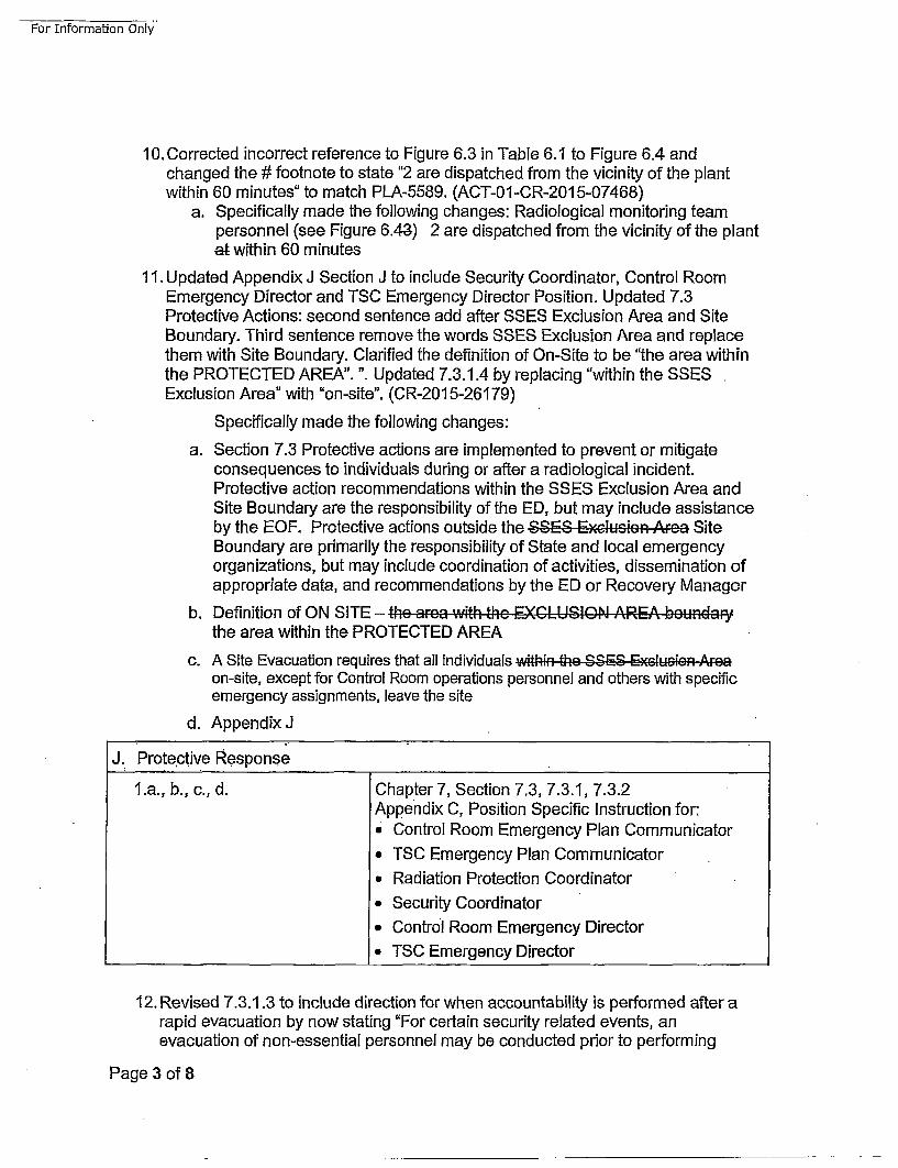
For Information Onlyt
10. Corrected incorrect reference to Figure 6.3 in Table 6.1 to Figure 6.4 andchanged the # footnote to state "2 are dispatched from the vicinity of the plantwithin 60 minutes" to match PLA-5589. (ACT-01-OR-2015-07468)
a. Specifically made the following changes: Radiological monitoring teampersonnel (see Figure 6.48) 2 are dispatched from the vicinity of the plantatwithin 60 minutes
11. Updated Appendix J Section J to include Security Coordinator, Control RoomEmergency Director and TSC Emergency Director Position. Updated 7.3Protective Actions: second sentence add after SSES Exclusion Area and SiteBoundary. Third sentence remove the words SSES Exclusion Area and replacethem with Site Boundary. Clarified the definition of On-Site to be "the area withinthe PROTECTED AREA". ". Updated 7.3.1.4 by replacing "within the SSESExclusion Area" with "on-site". (CR-201 5-26179)
Specifically made the following changes:
a. Section 7.3 Protective actions are implemented to prevent or mitigateconsequences to individuals during or after a radiological incident.Protective action recommendations within the SSES Exclusion Area andSite Boundary are the responsibility of the ED, but may include assistanceby the EOF. Protective actions outside the SSES Exclu-sion" .Area SiteBoundary are primarily the responsibility of State and local emergencyorganizations, but may include coordination of activities, dissemination ofappropriate data, and recommendations by the ED or Recovery Manager
b. Definition of ON SITE - the ... o.. ;+:h the, EXCLUSION .A.RE.A boun.. ,r','the area within the PROTECTED AREA
c. A Site Evacuation requires that all individuals ,within th, ee S -,ES • Exclusion ^,,eaon-site, except for Control Room operations personnel and others with specificemergency assignments, leave the site
d. Appendix J
J. Prote~ctive Response
l.a., b., c., d. Chapter 7, Section 7.3, 7.3.1, 7.3.2Appendix C, Position Specific Instruction for:, Control Room Emergency Plan Communicator
* TSC Emergency Plan Communicator
, Radiation Protection Coordinator* Security Coordinator. Control Room Emergency Director
* TSC Emergency Director
12. Revised 7.3.1.3 to include direction for when accountability is performed after arapid evacuation by now stating "For certain security related events, anevacuation of non-essential personnel may be conducted prior to performing
Page 3 of 8
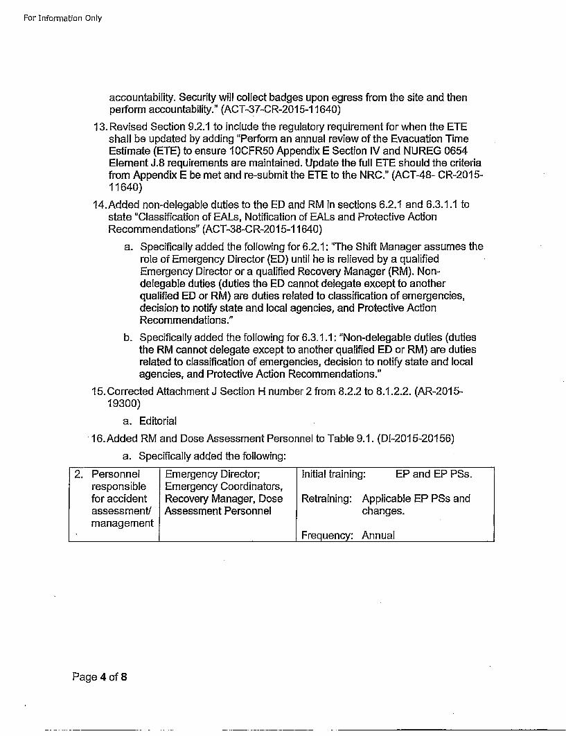
For Information Only
accountability. Security will collect badges upon egress from the site and thenperform accountability." (ACT-37-CR-20 15-11640)
13. Revised Section 9.2.1 to include the regulatory requirement for when the ETEshall be updated by adding "Perform an annual review of the Evacuation TimeEstimate (ETE) to ensure 10CFR50 Appendix E Section IV and NUREG 0654Element J.8 requirements are maintained. Update the full ETE should the criteriafrom Appendix E be met and re-submit the ETE to the NRC." (ACT-48- CR-201 5-11640)
14.Added non-delegable duties to the ED and RM in sections 6.2.1 and 6.3.1.1 tostate "Classification of EALs, Notification of EALs and Protective ActionRecommendations" (ACT-38-CR-20 15-11640)
a. Specifically added the following for 6.2.1: "The Shift Manager assumes therole of Emergency Director (ED) until he is relieved by a qualifiedEmergency Director or a qualified Recovery Manager (RM). Non-delegable duties (duties the ED cannot delegate except to anotherqualified ED or RM) are duties related to classification of emergencies,decision to notify state and local agencies, and Protective ActionRecommendations."
b. Specifically added the following for 6.3.1.1: "Non-delegable duties (dutiesthe RM cannot delegate except to another qualified ED or RM) are dutiesrelated to classification of emergencies, decision to notify state and localagencies, and Protective Action Recommendations."
15. Corrected Attachment J Section H number 2 from 8.2.2 to 8.1.2.2. (AR-2015-19300)
a. Editorial
16.Added RM and Dose Assessment Personnel to Table 9.1. (DI-2015-20156)
a. Specifically added the following:
2. Personnel Emergency Director; Initial training: EP and EP PSs.responsible Emergency Coordinators,for accident Recovery Manager, Dose Retraining: Applicable EP PSs andassessment! Assessment Personnel changes.management
____________ __________________ Frequency: Annual
Page 4 of 8
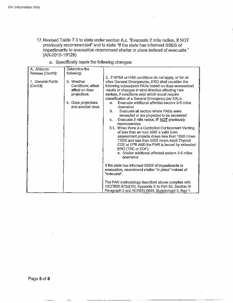
For Information Only
17. Revised Table 7.3 to state under section A.c. "Evacuate 2 mile radius, if NOTpreviously recommended" and to state "If the state has informed SSES ofimpediments to evacuation recommend shelter in place instead of evacuate."(AR-201 5-19129)
a. Specifically made the following changes:
A. AirborneRelease (Cont'd)
1. General Public(Cont'd)
Determine thefollowing:
3. WeatherConditions', effeeteffect on doseprojections.
4. Dose projectionsand avoided dose.
3. If RPSA or HAB conditions do not apply, or for allother General Emergencies, ERO shall consider thefollowing subsequent PARs based on dose assessmentresults or changes in wind direction affecting newsectors, if conditions exist which would requireclassification of a General Emergency per EALs:
a. Evacuate addlitional affected sectors 2-5 milesdownwind
b. Evacuate all sectors where PAGs wereexceeded or are projected to be exceeded
c. Evacuate 2 mile radius, IF NOT previouslyrecommended
3.1. When there is a Controlled Containment Ventingof less than an hour AND a valid doseassessment projects doses less than 1000 mremTEDE and less than 5000 mrem Adult ThyroidCDE at EPB AND the PAR is issued by extendedERO (TSC or EOF):a. Shelter additional affected sectors 2-5 miles
downwind
If the state has informed SSES of impediments toevacuation, recommend shelter "in place" instead of"evacuate".
The PAR methodology described above complies with10CFR50.47(b)(10), Appendix E to Part 50, Section IVParagraph 3 and NUREG-0654, Supplement 3, Rev 1.
Page 5 of 8
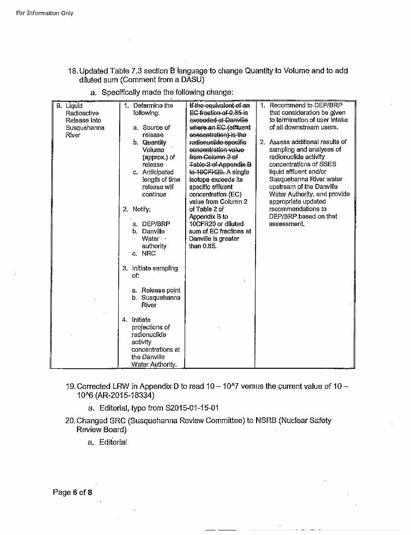
For Information Only
18. Updated Table 7.3 section B language to change Quantity to Volume and to adddiluted sum (Comment from a DASU)
a. Specifically made the following change:
B. LiquidRadioactiveRelease IntoSusquehannaRiver
1. Determine thefollowing:
a. Source ofrelease
b, uaat~tyVolume(approx.) ofrelease
c. Anticipatedlength of timerelease willcontinue
2. Notify:
a. DEP/BRPb. Danville
Waterauthority
c. NRC
3. Initiate samplingof:
a. Release pointb. Susquehanna
River
4. initiateprojections ofradionuclidieactivityconcentrations atthe DanvilleWater Authority.
EC fraction of 0.85
isotopedexteeds itsoshpeiniC (effluent
concentration (ElC)vuefrom Column 2 oofTable 2 of Apni
1e0CF-R20 sr inlued
cumonEntfractions (EC
Danville is greaterthan 0.85.
1. Recommend to DEP/BRPthat consideration be givento termination of user intakeof all downstream users.
2. Assess additional results ofsampling and analyses ofradionuclide activityconcentrations of SSESliquid effluent and/orSusquehanna River waterupstream of the DanvilleWater Authority, and provideappropriate updatedrecommendations toDEPIBRP based on thatassessment.
I"
19. Corrected LRW in Appendix D to read 10 - 10A7 versus the current value of 10 -1 0A6 (AR-201 5-18334)
a. Editorial, typo from S2015-01-15-01
20. Changed SRC (Susquehanna Review Committee) to NSRB (Nuclear SafetyReview Board)
a. Edit~orial
Page 6 of 8
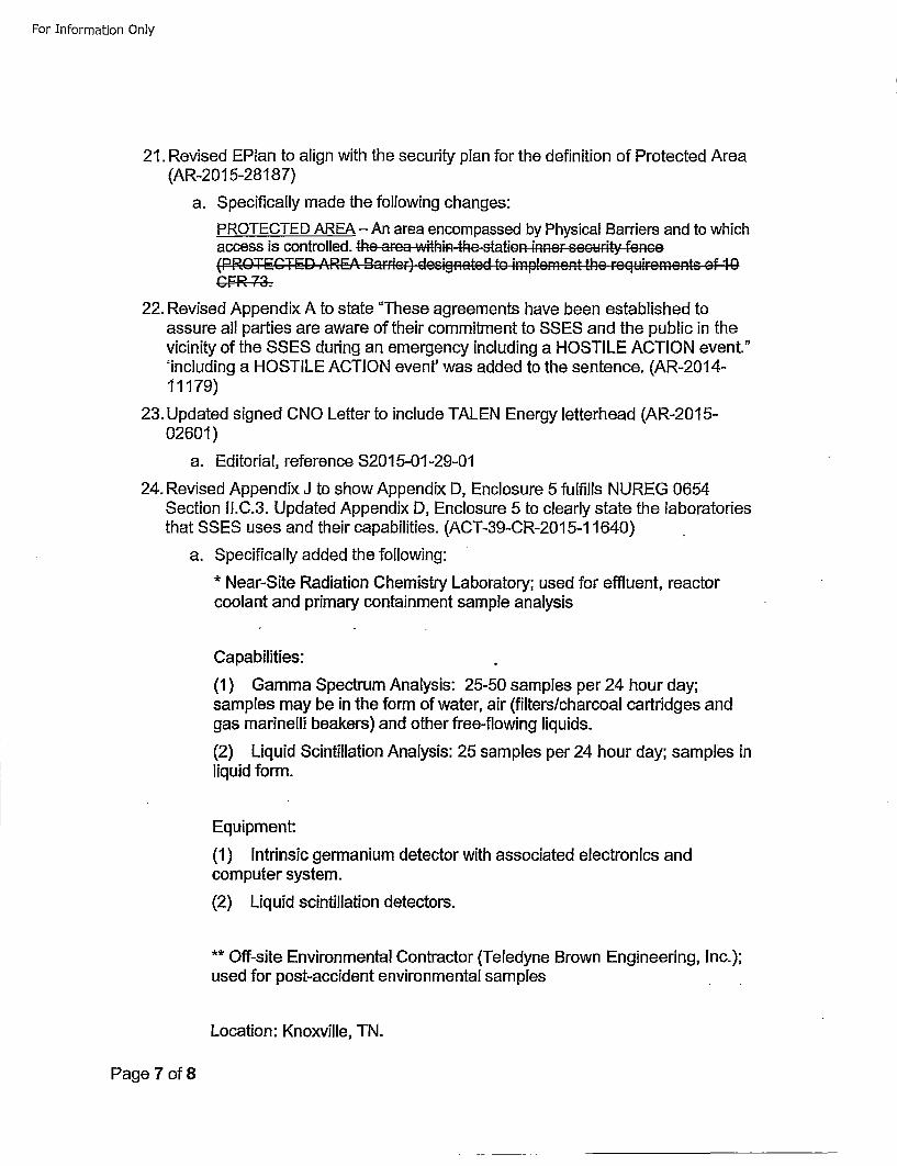
For Information Only
21. Revised EPlan to align with the security plan for the definition of Protected Area(AR-201 5-28187)
a. Specifically made the following changes:
PROTECTED AREA - An area encompassed by Physical Barriers and to whichaccess is controlled. the .. r... within the, stton, + nn, r ... c. rit. fenc..
22. Revised Appendix A to state "These agreements have been established toassure all parties are aware of their commitment to SSES and the public in thevicinity of the SSES during an emergency including a HOSTILE ACTION event."'including a HOSTILE ACTION event' was added to the sentence. (AR-2014-11179)
23. Updated signed CNO Letter to include TALEN Energy letterhead (AR-201 5-02601)
a. Editorial, reference 32015-01-29-01
24. Revised Appendix J to show Appendix D, Enclosure 5 fulfills NUREG 0654Section I1.C.3. Updated Appendix D, Enclosure 5 to clearly state the laboratoriesthat SSES uses and their capabilities. (ACT-39-CR-201 5-11640)
a. Specifically added the following:* Near-Site Radiation Chemistry Laboratory; used for effluent, reactorcoolant and primary containment sample analysis
Capabilities:
(1) Gamma Spectrum Analysis: 25-50 samples per 24 hour day;samples may be in the form of water, air (filters/charcoal cartridges andgas marinelli beakers) and other free-flowing liquids.
(2) Liquid Scintillation Analysis: 25 samples per 24 hour day; samples inliquid form.
Equipment:
(1) Intrinsic germanium detector with associated electronics andcomputer system.
(2) Liquid scintillation detectors.
** Off-site Environmental Contractor (Teledyne Brown Engineering, Inc.);used for post-accident environmental samples
Location: Knoxville, TN.
Page 7 of 8
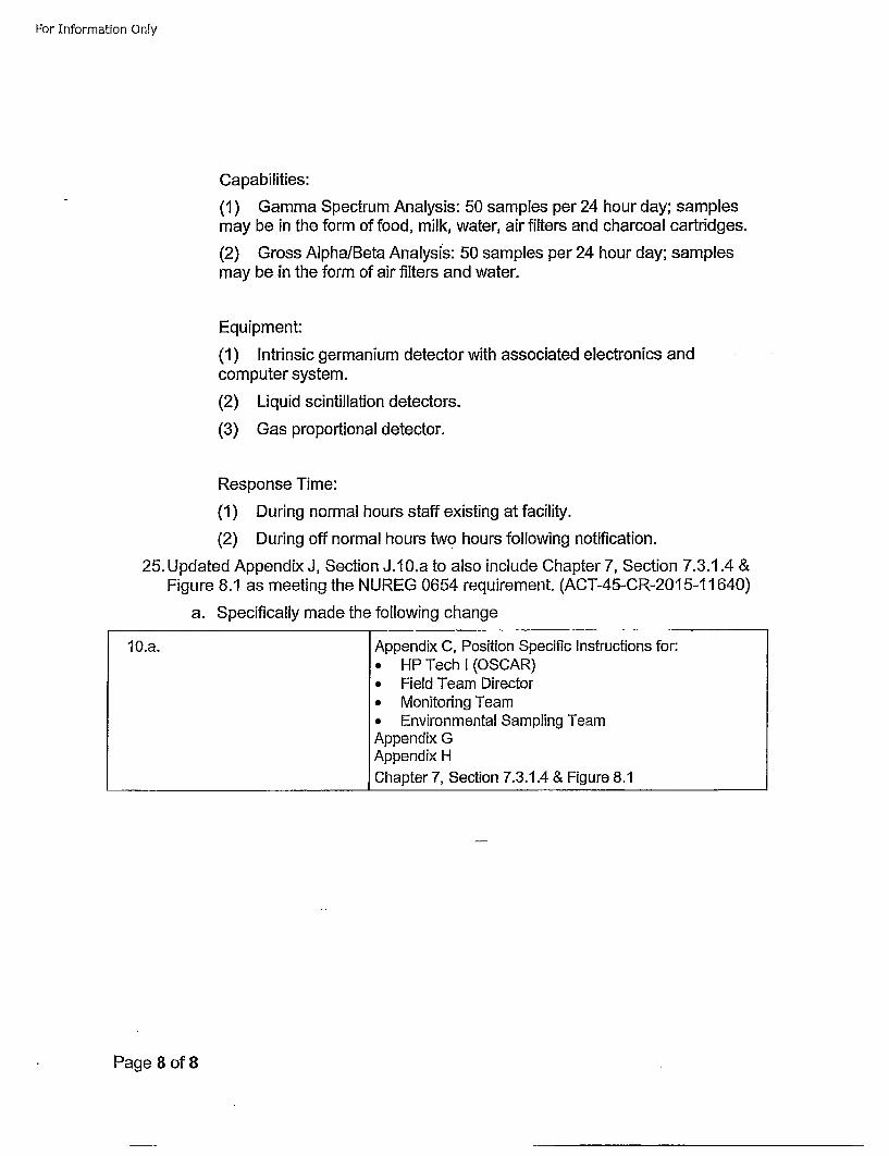
For Information Only
Capabilities:(1) Gamma Spectrum Analysis: 50 samples per 24 hour day; samplesmay be in the form of food, milk, water, air filters and charcoal cartridges.
(2) Gross Alpha/Beta Analysis: 50 samples per 24 hour day; samplesmay be in the form of air filters and water.
Equipment:
(1) Intrinsic germanium detector with associated electronics andcomputer system.
(2) Liquid scintillation detectors.
(3) Gas proportional detector.
Response Time:
(1) During normal hours staff existing at facility.
(2) During off normal hours two hours following notification.
25. Updated Appendix J, Section J.10.a to also include Chapter 7, Section 7.3.1.4 &Figure 8.1 as meeting the NUREG 0654 requirement. (ACT-45-CR-2015-11640)
a. Specifically made the following change
10.a. Appendix C, Position Specific Instructions for:• HP Tech I (OSCAR)* Field Team Director* Monitoring Team* Environmental Sampling TeamAppendix GAppendix H
_______________________Chapter 7, Section 7.3.1.4 & Figure 8.1
Page 8 of 8
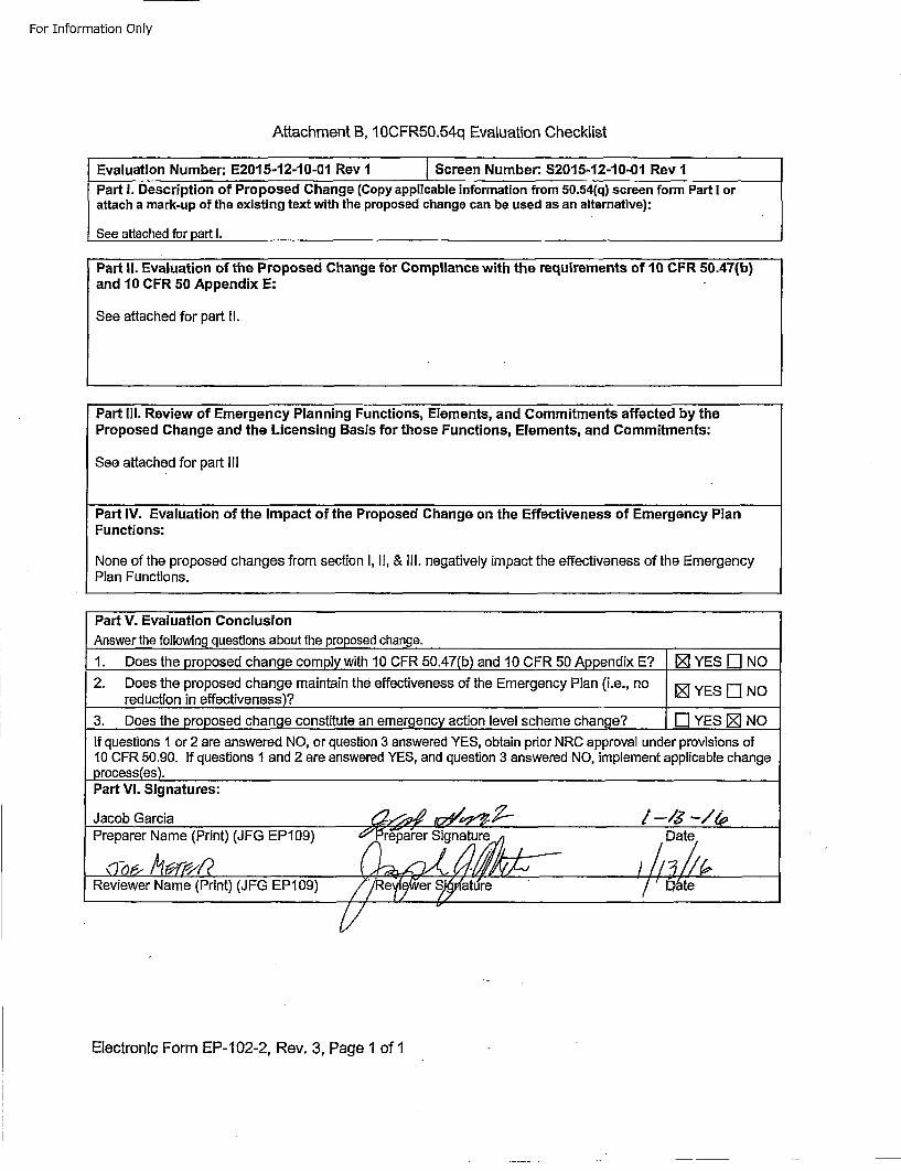
For Information Only
Attachment B, 10OCFR5O.54q Evaluation Checklist
Evaluation Number: E2015-12-10-01 Rev I Screen Number: $2015-12-10-01 Rev 1PartI. escipton f Popoed hang (Cpy pplcabe iforatin frm 5.54q) cren frm artI a
attach a mark-up of the existing text with the proposed change can be used as an alternative):
See attached for part I.
and 10 CFR 50 Appendix E:
See attached for part I1.
Part Ill. Review of Emergency Planning Functions, Elements, and Commitments affected by theProposed Change and the Licensing Basis for those Functions, Elements, and Commitments:
See attached for part Ill
Part IV. Evaluation of the Impact of the Proposed Change on the Effectiveness of Emergency PlanFunctions:
None of the proposed changes from section I, I1, & Ill. negatively impact the effectiveness of the EmergencyPlan Functions.
Part V. Evaluation ConclusionAnswer the following questions about the proposed change.1. Does the proposed change complI with 10 CFR 50.47b) and 10OCFR 5O Apendix E? I0]YESU[]NO
2. Does the proposed change maintain the effectiveness of the Emergency Plan (i.e., no YEriNreduction in effectiveness)..?]YE ]N
3. Does the proposed change constitute an emergency action level scheme change? [] YES [] NO
If questions 1 or 2 are answered NO, or question 3 answered YES, obtain prior NRC approval under provisions of10 CFR 50.90. If questions 1 and 2 are answered YES, and question 3 answered NO, implement applicable changeprocess(es).Part VI. Signatures:
Jacob Garcia -,• /•,-,• -/-J•-,•Preparer Name (Print) (JFG EP109) 6'0 reparer Sig[/ nature ,S'aur• ' / t/Date~ii•
Reviewer Name (Print) (JFG EPI09) /'/Re ejer auet
Electronic Form EP-102-2, Rev. 3, Page 1 of 1
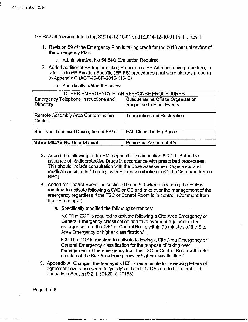
For Information Only
EP Rev 59 revision details for, S2014-12-10-01 and E2014-12-10-01 Part 1, Rev 1:
1. Revision 59 of the Emergency Plan is taking credit for the 2016 annual review ofthe Emergency Plan.
a. Administrative, No 54.54Q Evaluation Required
2. Added additional EP Implementing Procedures, EP Administrative procedure, inaddition to EP Position Specific (EP-PS) procedures (that were already present)to Appendix C (ACT-46-CR-201 5-11640)
a. Specifically added the below
OTHER EMERGENCY PLAN RESPONSE PROCEDURESEmergency Telephone Instructions and Susquehanna Offsite OrganizationDirectory Response to Plant Events
Remote Assembly Area Contamination Termination and Restoration
Control
Brief Non-Technical Description of EALs EAL Classification Bases
SSES MIDAS-NU User Manual Personnel Accountability
3. Added the following to the RM responsibilities in section 6.3.1.1 "Authorizeissuance of Radioprotective Drugs in accordance with prescribed procedures.This should include consultation with the Dose Assessment Supervisor andmedical consultants." To align with ED responsibilities in 6.2.1. (Comment from aRPC)
4. Added "or Control Room" in section 6.0 and 6.3 when discussing the EOF isrequired to activate following a SAE or GE and take over the management of theemergency regardless if the TSC or Control Room is in control. (Comment fromthe EP manager)
a. Specifically modified the following sentences:
6.0 "The EOF is required to activate following a Site Area Emergency orGeneral Emergency classification and take over management of theemergency from the TSC or Control Room within 90 minutes of the SiteArea Emergency or higher classification."
6.3 "The EOF is required to activate following a Site Area Emergency orGeneral Emergency classification for the purpose of taking overmanagement of the emergency from the TSC or Control Room within 90minutes of the Site Area Emergency or higher classification."
5. Appendix A, Changed the Manager of EP is responsible for reviewing letters ofagreement every two years to 'yearly' and added LOAs are to be completedannually to Section 9.2.1. (DI-201 5-201 63)
Page I of 8
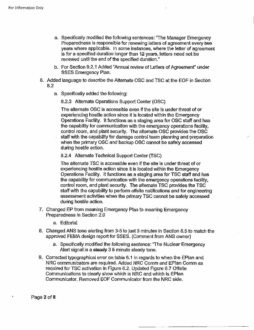
For Information Only
a. Specifically modified the following sentences: "The Manager EmergencyPreparedness is responsible for renewing letters of agreement every twoyears where applicable. In some instances, where the letter of agreementis for a specified duration longer than 12- years, letters need not berenewed until the end of the specified duration."5
b. For Section 9.2.1 Added "Annual review of Letters of Agreement" underSSES Emergency Plan.
6. Added language to describe the Alternate OSC and TSC at the EOF in Section8.2
a. Specifically added the following:
8.2.3 Alternate Operations Support Center (OSC)
The alternate OSC is accessible even if the site is under threat of orexperiencing hostile action since it is located within the EmergencyOperations Facility. It functions as a staging area for OSC staff and hasthe capability for communication with the emergency operations facility,control room, and plant security. The alternate OSC provides the OSCstaff with the capability for damage control team planning and preparationwhen the primary OSC and backup OSC cannot be safely accessedduring hostile action.
8.2.4 Alternate Technical Support Center (TSC)
The alternate TSC is accessible even if the site is under threat of orexperiencing hostile action since it is located within the EmergencyOperations Facility. It functions as a staging area for TSC staff and hasthe capability for communication with the emergency operations facility,control room, and plant security. The alternate TSC provides the TSCstaff with the capability to perform offsite notifications and for engineeringassessment activities when the primary TSC cannot be safely accessedduring hostile action.
7. Changed EP from meaning Emergency Plan to meaning EmergencyPreparedness in Section 2.0
a. Editorial
8. Changed ANS tone alerting from 3-5 to just 3 minutes in Section 8.5 to match theapproved FEMA design report for SSES. (Comment from ANS owner)
a. Specifically modified the following sentence: 'The Nuclear EmergencyAlert signal is a steady 3 5 minute steady tone.
9. Corrected typographical error on table 6.1 in regards to when the EPlan andNRC communicators are required. Added NRC Comm and EPlan Comm asrequired for TSC activation in Figure 6.2. Updated Figure 6.70OffsiteCommunications to clearly show which is NRC and which is EPlanCommunicator. Removed EOF Communicator from the NRC side.
Page 2 of 8
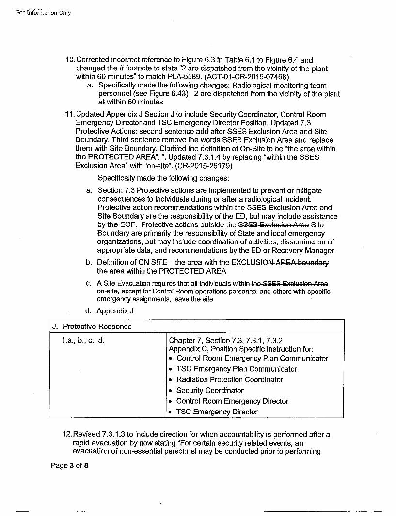
For Information Only
10. Corrected incorrect reference to Figure 6.3 in Table 6.1 to Figure 6.4 andchanged the # footnote to state "2 are dispatched from the vicinity of the plantwithin 60 minutes" to match PLA-5589. (ACT-01-CR-2015-07468)
a. Specifically made the following changes: Radiological monitoring teampersonnel (see Figure 6.48) 2 are dispatched from the vicinity of the plantat within 60 minutes
11. Updated Appendix J Section J to include Security Coordinator, Control RoomEmergency Director and TSC Emergency Director Position. Updated 7.3Protective Actions: second sentence add after SSES Exclusion Area and SiteBoundary. Third sentence remove the words SSES Exclusion Area and replacethem with Site Boundary. Clarified the definition of On-Site to be "the area withinthe PROTECTED AREA". ". Updated 7.3.1.4 by replacing "within the SSESExclusion Area" with "on-site". (CR-201 5-26179)
Specifically made the following changes:
a. Section 7.3 Protective actions are implemented to prevent or mitigateconsequences to individuals during or after a radiological incident.Protective action recommendations within the SSES Exclusion Area andSite Boundary are the responsibility of the ED, but may include assistanceby the ECE. Protective actions outside the SSES Exc'Jsion ,A, rc• SiteBoundary are primarily the responsibility of State and local emergencyorganizations, but may include coordination of activities, dissemination ofappropriate data, and recommendations by the ED or Recovery Manager
b. Definition of ON SITE - hc ...... with the• EXCLUSION AREAS bou.d. ,',,the area within the PROTECTED AREA
c. A Site Evacuation requires that all individuals within tho SSES Fxclu-sion ,Arcaon-site, except for Control Room operations personnel and others with specificemergency assignments, leave the site
d. Appendix J
J. Protective Response
l .a., b,, c., d. IChapter 7, Section 7.3, 7.3.1, 7.3.2Appendix C, Position Specific Instruction for:• Control Room Emergency Plan Communicator* TSC Emergency Plan Communicator* Radiation Protection Coordinator
* Security Coordinator• Control Room Emergency Director* TSC Emergency Director
12. Revised 7.3.1.3 to include direction for when accountability is performed after arapid evacuation by now stating "For certain security related events, anevacuation of non-essential personnel may be conducted prior to performing
Page 3 of 8
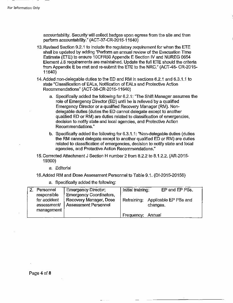
For Information Only
accountability. Security will collect badges upon egress from the site and thenperform accountability." (ACT-37-CR-201 5-11640)
13. Revised Section 9.2.1 to include the regulatory requirement for when the ETEshall be updated by adding "Perform an annual review of the Evacuation TimeEstimate (ETE) to ensure 10CFR50 Appendix E Section IV and NUREG 0654Element J.8 requirements are maintained. Update the full ETE should the criteriafrom Appendix E be met and re-submit the ETE to the NRC." (ACT-48- CR-2015-11640)
14.Added non-delegable duties to the ED and RM in sections 6.2.1 and 6.3.1.1 tostate "Classification of EALs, Notification of EALs and Protective ActionRecommendations" (ACT-38-CR-201 5-11640)
a. Specifically added the following for 6.2.1: "The Shift Manager assumes therole of Emergency Director (ED) until he is relieved by a qualifiedEmergency Director or a qualified Recovery Manager (RM). Non-delegable duties (duties the ED cannot delegate except to anotherqualified ED or RM) are duties related to classification of emergencies,decision to notify state and local agencies, and Protective ActionRecommendations."
b. Specifically added the following for 6.3.1.1: "Non-delegable duties (dutiesthe RM cannot delegate except to another qualified ED or RM) are dutiesrelated to classification of emergencies, decision to notify state and localagencies, and Protective Action Recommendations."
15. Corrected Attachment J Section H number 2 from 8.2.2 to 8.1.2.2. (AR-2015-19300)
a. Editorial
16.Added RM and Dose Assessment Personnel to Table 9.1. (DI-2015-20156)
a. Specifically added the following:
2. Personnel Emergency Director; Initial training: EP and EP PSs.responsible Emergency Coordinators,for accident Recovery Manager, Dose Retraining: Applicable EP PSs andassessment! Assessment Personnel changes.management
___________________Frequency: Annual
Page 4 of 8
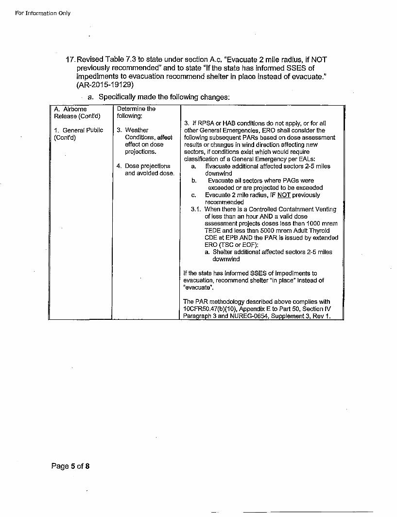
For Information Only
17. Revised Table 7.3 to state under section A.c. "Evacuate 2 mile radius, if NOTpreviously recommended" and to state "If the state has informed SSES ofimpediments to evacuation recommend shelter in place instead of evacuate."(AR-201 5-19129)
a. Specifically made the following changes:
A. AirborneRelease (Cont'd)
1. General Public(Cont'd)
Determine thefollowing:
3. WeatherConditions, effeeteffect on doseprojections.
4. Dose projectionsand avoided dose.
3. If RPSA or HAB conditions do not apply, or for allother General Emergencies, ERO shall consider thefollowing subsequent PARs based on dose assessmentresults or changes in wind direction affecting newsectors, if conditions exist which would requireclassification of a General Emergency per EALs:
a. Evacuate additional affected sectors 2-5 milesdownwind
b. Evacuate all sectors where PAGs wereexceeded or are projected to be exceeded
c. Evacuate 2 mile radius, IF NOT previouslyrecommended
3.1. When there is a Controlled Containment Ventingof less than an hour AND a valid doseassessment projects doses less than 1000 mremTEDE and less than 5000 mrem Adult ThyroidCDE at EPB AND the PAR is issued by extendedERO (TSC or EOF):a. Shelter additional affected sectors 2-5 miles
downwind
If the state has informed SSES of impediments toevacuation, recommend shelter "in place" instead of"evacuate".
The PAR methodology described above complies with10CFR50.47(b)(10), Appendix E to Part 50, Section IVParagqraph 3 and NUREG-0654, Supplement 3, Rev 1.
Page 5 of 8
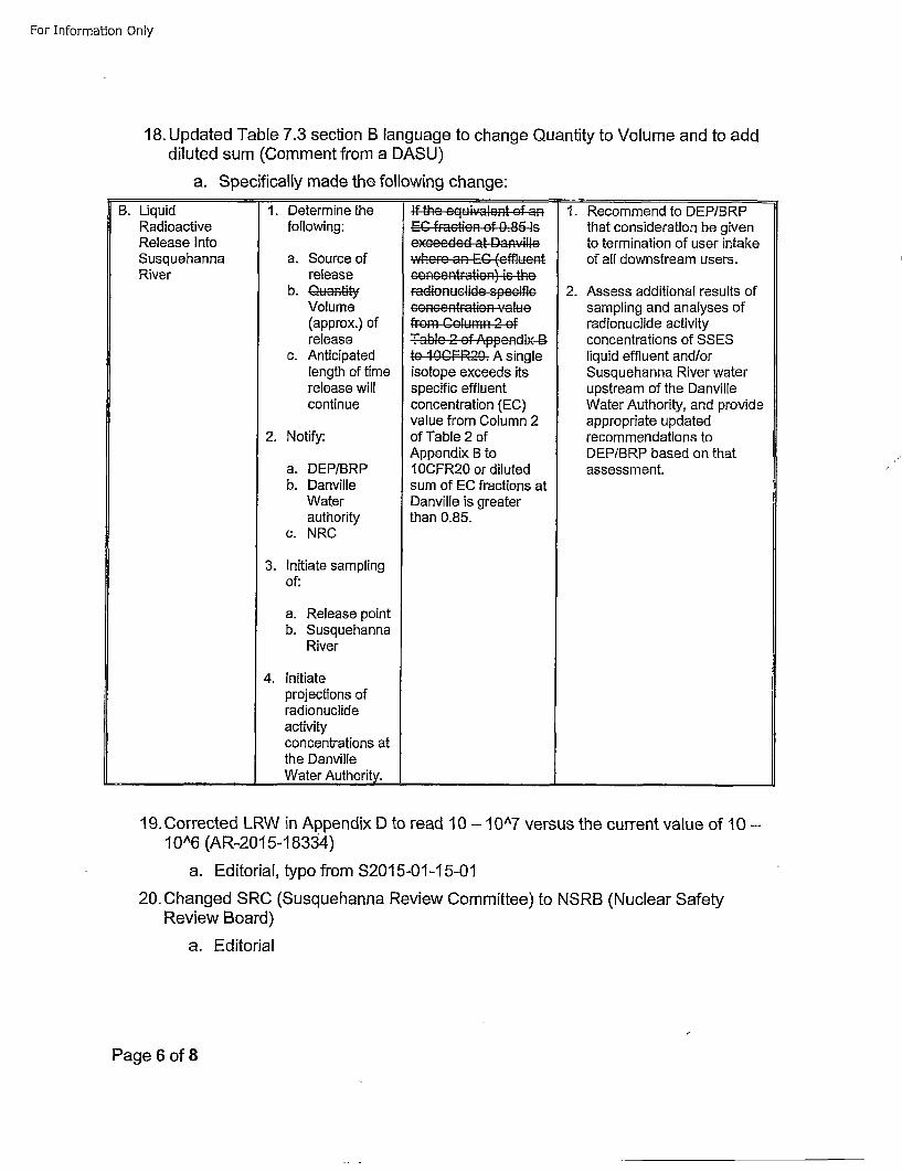
For Information Only
18. Updated Table 7.3 section B language to change Quantity to Volume and to adddiluted sum (Comment from a DASU)
a. Specifically made the following change:
B. LiquidRadioactiveRelease IntoSusquehannaRiver
1. Determine thefollowing:
a. Source ofrelease
b. iti ,Volume(approx.) ofrelease
c. Anticipatedlength of timerelease willcontinue
2. Notify:
a. DEP/BRPb. Danville
Waterauthority
c. NRC
3. Initiate samplingof:
a. Release pointb. Susquehanna
River
4. Initiateprojections ofradionuclideactivityconcentrations atthe DanvilleWater Authority.
Ifrthe Cquivahcn of aECfaction of Ap.85dis
theo an0CF0 (effnluensonetopetion)eds thsrspencific e pecificconccntration (ECu)vlefrom Column 2 a
Tal fAppendix B t
speCific0 effdluete
sum of EC fractions atDanville is greaterthan 0.85.
1. Recommend to DEP/BRPthat consideration be givento termination of user intakeof all downstream users.
2. Assess additional results ofsampling and analyses ofradionuclide activityconcentrations of SSESliquid effluent and/orSusquehanna River waterupstream of the DanvilleWater Authority, and provideappropriate updatedrecommendations toDEP/BRP based on thatassessment.
II
19.Corrected LRW in Appendix D to read 10 - 10A7 versus the current value of 10 -1 0^6 (AR-201 5-18334)
a. Editorial, typo from S2015-01-15-01
20. Changed SRC (Susquehanna Review Committee) to NSRB (Nuclear SafetyReview Board)
a. Editorial
Page 6 of 8
For Information Only
21. Revised EPlan to align with the security plan for the definition of Protected Area(AR-201 5-28187)
a. Specifically made the following changes:
PROTECTED AREA - An area encompassed by Physical Barriers and to whichaccess is controlled. the,, .. r.. w, i -thin the•,, station+'+;" inner'• .. ecur...t. fence•,x••, ...
22. Revised Appendix A to state "These agreements have been established toassure all parties are aware of their commitment to SSES and the public in thevicinity of the SSES during an emergency including a HOSTILE ACTION event."'including a HOSTILE ACTION event' was added to the sentence. (AR-20 14-11179)
23. Updated signed CNO Letter to include TALEN Energy letterhead (AR-201 5-02601)
a. Editorial, reference S201 5-01-29-01
24. Revised Appendix J to show Appendix D, Enclosure 5 fulfills NUREG 0654Section lI.C.3. Updated Appendix D, Enclosure 5 to clearly state the laboratoriesthat SSES uses and their capabilities. (ACT-39-CR-201 5-11640)
a. Specifically added the following:* Near-Site Radiation Chemistry Laboratory; used for effluent, reactorcoolant and primary containment sample analysis
Capabilities:
(1) Gamma Spectrum Analysis: 25-50 samples per 24 hour day;samples may be in the form of water, air (filters/charcoal cartridges andgas marinelli beakers) and other free-flowing liquids.
(2) Liquid Scintillation Analysis: 25 samples per 24 hour day; samples inliquid form.
Equipment:
(1) Intrinsic germanium detector with associated electronics andcomputer system. - -
(2) Liquid scintillation detectors.
** Off-site Environmental Contractor (Teledyne Brown Engineering, Inc.);
used for post-accident environmental samples
Location: Knoxville, TN.
Page 7 of 8
For Information Only
Capabilities:(1) Gamma Spectrum Analysis: 50 samples per 24 hour day; samplesmay be in the form of food, milk, water, air filters and charcoal cartridges.
(2) Gross Alpha/Beta Analysis: 50 samples per 24 hour day; samplesmay be in the form of air filters and water.
Equipment:
(1) Intrinsic germanium detector with associated electronics andcomputer system.
(2) Liquid scintillation detectors.
(3) Gas proportional detector.
Response Time:
(1) During normal hours staff existing at facility.
(2) During off normal hours two hours following notification.
25. Updated Appendix J, Section J.10.a to also include Chapter 7, Section 7.3.1.4 &Figure 8.1 as meeting the NUREG 0654 requirement. (ACT-45-CR-201 5-11640)
a. Specificatly made the following change
10.a. Appendix C, Position Specific Instructions for:* HP Tech I (OSCAR)* Field Team Director* Monitoring Team• Environmental Sampling TeamAppendix GAppendix HChapter 7, Section 7.3.1.4 & Figure 8.1
Page 8 of 8
For Information Only
E2015-12-lO-01 Part II
1. Administrative, No Evaluation Required.
2. The regulation in 10 CFR 50.47(b)(16) states the following:
Responsibilities for plan development and review and for distribution of emergency plans are
established, and planners are properly trained.
Adding EP Implementing Procedures, EP Administrative procedures, in addition to EP Position Specific
(EP-PS) procedures (that were already issued and evaluated under the 1DCFR50.54q process) to
Appendix C of the Emergency Plan is in compliance with the above regulation.
Appendix E to 10 CFR Part 50 does not contain any supporting requirements.
3. The regulation in 10 CFR 50.47(b)(10) states the following:
A range of protective actions has been developed for the plume exposure pathway EPZ foremergency workers and the public. In developing this range of actions, consideration has beengiven to evacuation, sheltering, and, as a supplement to these, the prophylactic use ofpotassium iodide (KI), as appropriate. Evacuation time estimates have been developed byapplicants and licensees. Licensees shall update the evacuation time estimates on a periodicbasis. Guidelines for the choice of protective actions during an emergency, consistent withFederal guidance, are developed and in place, and protective actions for the ingestion exposurepathway EPZ appropriate to the locale have been developed.
IOCFR50 Appendix E IV.B.
The means to be used for determining the magnitude of, and for continually assessing the
impact of, the release of radioactive materials shall be described, including emergency action
levels that are to be used as criteria for determining the need for notification and participation
of local and State agencies, the Commission, and other Federal agencies, and the emergency
action levels that are to be used for determining when and what type of protective measures
should be considered within and outside the site boundary to protect health and safety. The
emergency action levels shall be based on in-plant conditions and instrumentation in addition to
onsite and offsite monitoring.
Adding the capability of the Recovery Manager (RM) to authorize issuing KI is in accordance with the
above regulation since that position is equivalent in authority to the Emergency Director (ED).
Page Ilof 12
For Information Only
4. The regulation in 10 CFR 50.47(b)(2) states the following:
On-shift facility licensee responsibilities for emergency response are unambiguously defined,
adequate staffing to provide initial facility accident response in key functional areas is
maintained at all times, timely augmentation of response capabilities is available and the
interfaces among various onsite response activities and offsite support and response activities
are specified.
10CFR50 Appendix E IV.E.8.d.
For nuclear power reactor licensees, an alternative facility (or facilities) that would be accessible even if
the site is under threat of or experiencing hostile action, to function as a staging area for augmentation
of emergency response staff and collectively having the following characteristics: the capability for
communication with the emergency operations facility, control room, and plant security; the capability
to perform offsite notifications; and the capability for engineering assessment activities, including
damage control team planning and preparation; for use when onsite emergency facilities cannot be
safely accessed during hostile action;
Allowance for the Emergency Operations Facility (EOF) to also accept Command and Control directly
from the Control Room (CR) and not just the Technical Support Center (TSC) in certain security related
events is in accordance with Emergency Plan definition # 96 for the TSC and its associated footnote,
page 59 footnote and page 107 footnote and is in compliance with the above regulation.
5. The regulation in 10 CFR 50.47(b)(16) states the following:
Responsibilities for plan development and review and for distribution of emergency plans are
established, and planners are properly trained.
Changing that the Manager of EP is responsible for reviewing letters of agreement from every twoyears to 'yearly' and adding LOAs are to be completed annually is more conservative than the current
language and is in compliance with the above regulation.
Appendix E to 10 CFR Part 50 does not contain any supporting requirements.
6. The regulation in 10 CFR 50.47(b)(8) states the following:
Adequate emergency facilities and equipment to support the emergency response are provided
and maintained.
Page 2 of 12
For Information Only
10CFR5O Appendix E IV.E.8.d
For nuclear power reactor licensees, an alternative facility (or facilities) that would be accessible
even if the site is under threat of or experiencing hostile action, to function as a staging area for
augmentation of emergency response staff and collectively having the following characteristics:
the capability for communication with the emergency operations facility, control room, and
plant security; the capability to perform offsite notifications; and the capability for engineering
assessment activities, including damage control team planning and preparation, for use when
onsite emergency facilities cannot be safely accessed during hostile action.
Adding language to the Emergency Plan to describe the physical capabilities of the Alternate OSC and
Alternate TSC is in compliance with the above regulations.
7. Editorial, No Evaluation Required.
8. The regulation in 10 CFR 50.47(b)(5) states the following:
Procedures have been established for notification, by the licensee, of State and local response
organizations and for notification of emergency personnel by all organizations; the content of
initial and follow-up messages to response organizations and the public has been established;and means to provide early notification and clear instruction to the populace within the plume
exposure pathway Emergency Planning Zone have been established.
10CFR5O Appendix E IV.D.1 and IV.D.3
Administrative and physical means for notifying local, State, and Federal officials and agencies
and agreements reached with these officials and agencies for the prompt notification of the
public and for public evacuation or other protective measures, should they become necessary,
shall be described. This description shall include identification of the appropriate officials, by
title and agency, of the State and local government agencies within the EPZs.
A licensee shall have the capability to notify responsible State and local governmental agencies
within 15 minutes after declaring an emergency. The licensee shall demonstrate that the
appropriate governmental authorities have the capability to make a public alerting and
notification decision promptly on being informed by the licensee of an emergency condition.
Prior to initial operation greater than 5 percent of rated thermal power of the first reactor at a
site, each nuclear power reactor licensee shall demonstrate that administrative and physical
means have been established for alerting and providing prompt instructions to the public within
the plume exposure pathway EPZ. The design objective of the prompt public alert and
notification system shall be to have the capability to essentially complete the initial alerting and
initiate notification of the public within the plume exposure pathway EPZ within about 15
Page 3 of 12
For Information Only
minutes. The use of this alerting and notification capability will range from immediate alertingand notification of the public (within 15 minutes of the time that State and local officials are
notified that a situation exists requiring urgent action) to the more likely events where there is
substantial time available for the appropriate governmental authorities to make a judgment
whether or not to activate the public alert and notification system. The alerting and notification
capability shall additionally include administrative and physical means for a backup method of
public alerting and notification capable of being used in the event the primary method of
alerting and notification is unavailable during an emergency to alert or notify all or portions of
the plume exposure pathway EPZ population. The backup method shall have the capability to
alert and notify the public within the plume exposure pathway EPZ, but does not need to meet
the 15-minute design objective for the primary prompt public alert and notification system.
When there is a decision to activate the alert and notification system, the appropriate
governmental authorities will determine whether to activate the entire alert and notification
system simultaneously or in a graduated or staged manner. The responsibility for activating such
a public alert and notification system shall remain with the appropriate governmental
authorities.
Changing that the ANS tone alert signal is 3 minute steady tone from a steady 3-5 minute tone to
match the approved FEMA design report is in compliance with the above regulations.
9. Administrative. The original change to Table 6.1 that describes a TSC Eplan Communicator and a
TSC NRC Communicator vs. two TSC Communicators is found in Emergency Plan revision 58 and wasevaluated in E2014-06-19-03. This change to Table 6.1 corrects a vertical alignment error thatoccurred in revision 58. The values in the TSC column needed moved down one row. The update to
Figure 6.2 and 6.7 is administrative to make it congruent with Table 6.1. No addition evaluation
required.
10. The regulation in 10 CFR 50.47(b)(2) states the following:
On-shift facility licensee responsibilities for emergency response are unambiguously defined,
adequate staffing to provide initial facility accident response in key functional areas is
maintained at all times, timely augmentation of response capabilities is available and the
interfaces among various onsite response activities and offsite support and response activities
a re specified.
10CFR50 Appendix E IV.C. Activation of Emergency Organization
1. The entire spectrum of emergency conditions that involve the alerting or activating of
progressively larger segments of the total emergency organization shall be described. The
communication steps to be taken to alert or activate emergency personnel under each class of
Page 4 of 12
For Information Only
emergency shall be described. Emergency action levels (based not only on onsite and offsiteradiation monitoring information but also on readings from a number of sensors that indicate a
potential emergency, such as the pressure in containment and the response of the Emergency
Core Cooling System) for notification of offsite agencies shall be described. The existence, but
not the details, of a message authentication scheme shall be noted for such agencies. The
emergency classes defined shall include: (1) Notification of unusual events, (2) alert, (3) site area
emergency, and (4) general emergency. These classes are further discussed in NUREG-
0654/FE MA-REP-i.
2. By June 20, 2012, nuclear power reactor licensees shall establish and maintain the capabiiity
to assess, classify, and declare an emergency condition within 15 minutes after the availability of
indications to plant operators that an emergency action level has been exceeded and shallpromptly declare the emergency condition as soon as possible following identification of the
appropriate emergency classification level. Licensees shall not construe these criteria as a graceperiod to attempt to restore plant conditions to avoid declaring an emergency action due to an
emergency action level that has been exceeded. Licensees shall not construe these criteria aspreventing implementation of response actions deemed by the licensee to be necessary to
protect public health and safety provided that any delay in declaration does not deny the Stateand local authorities the opportunity to implement measures necessary to protect the public
health and safety
Changing the figure reference is editorial to correct an obvious typographical error. Changing thefootnote to read 2 are dispatched from the vicinity of the plant within 60 minutes from 'at 60 minutes'to match what was submitted to the NRC in PLA-S589 is in compliance with the above regulation.
11. The regulation in 10 CFR 50.47(b)(10) states the following:
A range of protective actions has been developed for the plume exposure pathway EPZ foremergency workers and the public. In developing this range of actions, consideration has beengiven to evacuation, sheltering, and, as a supplement to these, the prophylactic use ofpotassium iodide (KI), as appropriate. Evacuation time estimates have been developed byapplicants and licensees. Licensees shall update the evacuation time estimates on a periodicbasis. Guidelines for the choice of protective actions during an emergency, consistent withFederal guidance, are developed and in place, and protective actions for the ingestion exposurepathway EPZ appropriate to the locaile have been devel0•d.
10CFR5O Appendix E IV.B.
The means to be used for determining the magnitude of, and for continually assessing theimpact of, the release of radioactive materials shall be described, including emergency action
Page 5 of 12
For- Information Only
levels that are to be used as criteria for determining the need for notification and participationof local and State agencies, the Commission, and other Federal agencies, and the emergency
action levels that are to be used for determining when and what type of protective measures
should be considered within and outside the site boundary to protect health and safety. The
emergency action levels shall be based on in-plant conditions and instrumentation in addition to
onsite and offsite monitoring.
Adding the Emergency Director (ED) has responsibility for protective actions of personnel within theplant Exclusion Area and Site Boundary (i.e. property controlled by SSES) is in compliance with the
above regulation since protective actions outside the Site Boundary are primarily the responsibility of
State and local emergency organizations once a GE and PAR have been communicated.
The definition of ON-SITE was changed from Exclusion Area to the area within the Protected Area
since the Protected Area is used for personnel accountability. The change is in compliance with the
above regulation since ON-SITE is contained within the Site Boundary (as does the Exclusion Area) and
remains within the protective action recommendations required by section 7.3 of the emergency plan.
Adding additional positions that are responsible for protective actions within the Site Boundary toAppendix J in the EPlan is in compliance with the above regulation.
12. The regulation in 10 CFR 50.47(b)(10) states the following:
A range of protective actions has been developed for the plume exposure pathway EPZ foremergency workers and the public. In developing this range of actions, consideration has beengiven to evacuation, sheltering, and, as a supplement to these, the prophylactic use ofpotassium iodide (KI), as appropriate. Evacuation time estimates have been developed byapplicants and licensees. Licensees shall update the evacuation time estimates on a periodicbasis. Guidelines for the choice of protective actions during an emergency, consistent withFederal guidance, are developed and in place, and protective actions for the ingestion exposurepathway EPZ appropriate to the locale have been developed.
lOCFR50 Appendix E IV.B.
By June 20, 2012, for nuclear power reactor licensees, these action levels must include hostile
action that may adversely affect the nuclear power plant. The initial emergency action levels
shall be discussed and agreed on by the applicant or licensee and state and local governmental
authorities, and approved by the NRC. Thereafter, emergency action levels shall be reviewed
with the State and local governmental authorities on an annual basis.
Adding that security will collect badges upon egress from the site and then perform accountability(reference SI-SO-008) for those instances when site evacuation is need prior to conducting normal
Page 6 of 12
For Information Only
accountability (security event) is in compliance with the above regulation since it ensures protectiveactions of on-site personnel.
13. The regulation in 10 CFR 50.47(b)(10) states the following:
A range of protective actions has been developed for the plume exposure pathway EPZ foremergency workers and the public. In developing this range of actions, consideration has beengiven to evacuation, sheltering, and, as a supplement to these, the prophylactic use ofpotassium iodide (KI), as appropriate. Evacuation time estimates have been developed byapplicants and licensees. Licensees shall update the evacuation time estimates on a periodicbasis. Guidelines for the choice of protective actions during an emergency, consistent withFederal guidance, are developed and in place, and protective actions for the ingestion exposurepathway EPZ appropriate to the locale have been developed.
1OCFR5O Appendix E IV.5 and IV.6:
During the years between decennial censuses, nuclear power reactor licensees shall estimate
EPZ permanent resident population changes once a year, but no later than 365 days from the
date of the previous estimate, using the most recent U.S. Census Bureau annual resident
population estimate and State/local government population data, if available. These licensees
shall maintain these estimates so that they are available for NRC inspection during the period
between decennial censuses and shall submit these estimates to the NRC with any updated ETE
analysis.
If at any time during the decennial period, the EPZ permanent resident population increases
such that it causes the longest ETE value for the 2-mile zone or 5-mile zone, including all
affected Emergency Response Planning Areas, or for the entire 10-mile EPZ to increase by 25
percent or 30 minutes, whichever is less, from the nuclear power reactor licensee's currently
NRC approved or updated ETE, the licensee shall update the ETE analysis to reflect the impact of
that population increase. The licensee shall submit the updated ETE analysis to the NRC under
§ 50.4 no later than 365 days after the licensee's determination that the criteria for updating the
ETE have been met and at least 180 days before using it to form protective action
recommendations and providing it to State and local governmental authorities for use in
developing offsite protective action strategies.
Adding direction to perform an annual review of the ETE in accordance with the applicable portions of
10CFRS0 Appendix E IV and NRUEG 0634 ensures compliance with the above regulations.
14. The regulation in 10 CFR 50.47(b)(2) states the following:
On-shift facility licensee responsibilities for emergency response are unambiguously defined,
adequate staffing to provide initial facility accident response in key functional areas is
Page 7 of 12
For Information Only
maintained at all times, timely augmentation of response capabilities is available and theinterfaces among various onsite response activities and offsite support and response activities
are specified.
IOCFR50 Appendix E IV.A.2
A description of the onsite emergency response organization (ERO) with a detailed discussion of:
a. Authorities, responsibilities, and duties of the individual(s) who will take charge during an
emergency;
b. Plant staff emergency assignments;
c. Authorities, responsibilities, and duties of an onsite emergency coordinator who shall be in
charge of the exchange of information with offsite authorities responsible for coordinating and
implementing offsite emergency measures.
Adding the ED and RM responsibilities that may not be delegated to meet the requirements in NUREG
0654 Section ll.B.4 ensures compliance with the above regulations.
15. Editorial, No Evaluation Required.
16. The regulation in 10 CFR 50.47(b)(15) states the following:
Radiological emergency response training is provided to those who may be called on to assist in
an emergency.
lOCERSO Appendix E IV.F.1
The program to provide for: (a) The training of employees and exercising, by periodic drills, of
emergency plans to ensure that employees of the licensee are familiar with their specific emergency
response duties, and (b) The participation in the training and drills by other persons whose assistance
may be needed in the event of a radiological emergency shall be described. This shall include a
description of specialized initial training and periodic retraining programs to be provided to each of the
following categories of emergency personnel:
i. Directors and/or coordinators of the plant emergency organization;
ii. Personnel responsible for accident assessment, including control room shift personnel;
iii Radiological monitoring teams;
iv. Fire control teams (fire brigades);
Page 8 of 12
For Information Only
v. Repair and damage control teams;
vi. First aid and rescue teams;
vii. Medical support personnel;
viii. Licensee's headquarters support personnel;
ix. Security personnel.
Adding the RM and Dose Assessment personnel to the table that delineates training of SSESEmergency Response Personnel (personnel responsible for accident assessment/management) is in
compliance with the above regulations.
17. The changes to Table 7.3 for the airborne release PAR is evaluated in E2014-1O-29-01 revision 3.
18. The regulation in 10 CFR 50.47(b)(9) states the following:
Adequate methods, systems, and equipment for assessing and monitoring actual or potential
offsite consequences of a radiological emergency condition are in use.
The regulation in 10 CFR 50.47(b)(10) states the following:
A range of protective actions has been developed for the plume exposure pathway EPZ foremergency workers and the public. In developing this range of actions, consideration has beengiven to evacuation, sheltering, and, as a supplement to these, the prophylactic use ofpotassium iodide (KI), as appropriate. Evacuation time estimates have been developed byapplicants and licensees. Licensees shall update the evacuation time estimates on a periodicbasis. Guidelines for the choice of protective actions during an emergency, consistent withFederal guidance, are developed and in place, and protective actions for the ingestion exposurepathway EPZ appropriate to the locale have been developed.
1OCFR50 Appendix E IV.B.
The means to be used for determining the magnitude of, and for continually assessing the
impact of, the release of radioactive materials shall be described, including emergency action
levels that are to be used as criteria for determining the need for notification and participation
of local and State agencies, the Commission, and other Federal agencies, and the emergency
action levels that are to be used for determining when and what type of protective measures
should be considered within and outside the site boundary to protect health and safety. The
Page 9 of 12
For Information Only
emergency action levels shall be based on in-plant conditions and instrumentation in addition toonsite and offsite monitoring.
10CFR5O Appendix E IV.E.2.
Equipment for determining the magnitude of and for continuously assessing the impact of the
release of radioactive materials to the environment.
The changes to Table 7.3 for the liquid release PAR are grammatical in nature for enhanced readability
and do not constitute a technical change. Therefore the changes remain in compliance with the
above regulations.
19. Editorial for previous typographical error. See S2015-01-5-01. No additional Evaluation Required.
20. Editorial, No Evaluation Required.
21. The regulation in 10 CFR 50.47(b)(16) states the following:
Responsibilities for plan development and review and for distribution of emergency plans are
established, and planners are properly trained.
The change to the definition of PROTECTED AREA is to match what is in the Physical Security Plan and
does not constitute a technical change. There is no practical difference from an Emergency Plan
implementation standpoint. The area encompassed is the same. Therefore the changes remain in
compliance with the above regulations.
Appendix E to 10 CFR Part 50 does not contain any supporting requirements.
22. The regulation in 10 CFR 50.47(b)(3) states the following:
Arrangements for requesting and effectively using assistance resources have been made,
arrangements to accommodate State and local staff at the licensee's Emergency Operations
Facility have been made, and other organizations capable of augmenting the planned response
have been identified.
1OCFR5O Appendix E IV.A.7.
Page 10 of 12
For Information Only
By June 23, 2014, identification of, and a description of the assistance expected from,appropriate State, local, and Federal agencies with responsibilities for coping with emergencies,
including hostile action at the site. For purposes of this appendix, "hostile action" is defined as
an act directed toward a nuclear power plant or its personnel that includes the use of violent
force to destroy equipment, take hostages, and/or intimidate the licensee to achieve an end.This includes attack by air, land, or water using guns, explosives, projectiles, vehicles, or other
devices used to deliver destructive force.
Adding that LOA's have been established during all emergencies 'including a HOSTILE ACTION event' is
in compliance with the above regulations. Details of how the above are accomplished are found in
EP-O0-002 and AR-1066721.
23. Changing the letterhead for the annual CNO letter is editorial. No Evaluation is required.
Reference E2015-01-29-01 for transition from PPL to Talen.
24. The regulation in 10 CFR 50.47(b)(3) states the following:
Arrangements for requesting and effectively using assistance resources have been made,arrangements to accommodate State and local staff at the licensee's Emergency Operations
Facility have been made, and other organizations capable of augmenting the planned response
have been identified.
10CFR50 Appendix E IV.A.6.
A description of the local offsite services to be provided in support of the licensee's emergency
organization.
Adding the capabilities the analytical facilities listed in Enclosure 5 to Appendix and their expectedavailability to provide radiological monitoring and analyses services which can be used in anemergency is in compliance with the above regulations. Updating Appendix i to show Appendix D,Enclosure 5 fulfills NUREG 0654 Section lIhC.3 is also in compliance with the above regulations.
25. The regulation in 10 CFR 50.47(b)(10) states the following:
A range of protective actions has been developed for the plume exposure pathway EPZ foremergency workers and the public. In developing this range of actions, consideration has beengiven to evacuation, sheltering, and, as a supplement to these, the prophylactic use ofpotassium iodide (KI), as appropriate. Evacuation time estimates have been developed byapplicants and licensees. Licensees shall update the evacuation time estimates on a periodic
Page 11 of 12
For Information Only
basis. Guidelines for the choice of protective actions during an emergency, consistent withFederal guidance, are developed and in place, and protective actions for the ingestion exposurepathway EPZ a~ppropriate to the locale have been developed.
Adding the "roadmap" to additional sections of the Emergency Plan that comply with NUREG-0654section II.J.1O.a is in compliance with the above regulation. No technical content change.
No corresponding requirements in 1OCFR50 Appendix E.
Page 12 of 12
For Information Only
E2015-12-10-01 Part Ill
1. Administrative, No Evaluation Required.
2. Two emergency planning functions have been defined for planning standard 16:
(1) Responsibility for emergency plan development and review is established.
(2) Planners responsible for emergency plan development and maintenance are
properly trained.
The applicable planning element from NUREG-0654 is ll.P.7 - Each plan shall contain as an appendix
listing, by title, procedures required to implement the plan. The listing shall include the section(s) of the
plan to be implemented by each procedure.
There are no additional commitments associated with this section of the emergency plan.
Adding EP procedures does not negatively affect Emergency Planning Functions, Elements, and
Commitments affected by the Proposed Change and the Licensing Basis for those Functions, Elements,
and Commitments because it completes the list of procedures required by NUREG-0654.
3. Four emergency planning functions have been defined for planning standard 10:
(1) A range of public PARs is available for implementation during emergencies.
(2) Evacuation time estimates for the population located in the plume exposure pathway EPZ
are available to support the formulation of PARs and have been provided to State and local
governmental authorities.
(3) A range of protective actions is available for plant emergency workers during emergencies,
including those for hostile action events.
(4) KI is available for implementation as a protective action recommendation in those
jurisdictions that chose to provide KI to the public.
The applicable planning element from NUREG-0654 is Il.J.6 - Each licensee shall, for individuals
remaining or arriving onsite during the emergency, make provisions for:
a. Individual respiratory protection;
b. Use of protective clothing; and
c. Use of radioprotective drugs, (e.g., individual thyroid protection).
Page 1 of 10
For Information Only
There are no additional commitments associated with this section of the emergency plan.
The provisions in NSIR/DPR-ISG-O1 section IV.F are not applicable to this change.
Adding the capability of the Recovery Manager (RM) to authorize issuing El does not negatively affect
Emergency Planning Functions, Elements, and Commitments affected by the Proposed Change and the
Licensing Basis for those Functions, Elements, and Commitments because that position is~equivalent in
authority to the Emergency Director (ED) and ensures use the appropriate use of KI no matter which
facility has command and control.
4. Two emergency planning functions have been defined for planning standard 2:
(1) The process ensures that onshift emergency response responsibilities are staffed and
assigned.
(2) The process for timely augmentation of onshift staff is established and maintained.
The applicable planning element from NUREG-0654 is ll.B.3 - Each licensee shall identify a line ofsuccession for the emergency coordinator position and identify the specific conditions for higher level
utility officials assuming this function.
There are no additional commitments associated with this section of the emergency plan.
The provisions in NSIR/DPR-ISG-01 section IV.D are applicable to this change.
Allowance for the Emergency Operations Facility (EOF) to also accept Command and Control directly
from the Control Room (CR) and not just the Technical Support Center (TSC) in certain security related
events does not negatively affect Emergency Planning Functions, Elements, and Commitments
affected by the Proposed Change and the Licensing Basis for those Functions, Elements, and
Commitments because it allows the EOF to relieve the control room of specific emergency plan
responsibilities to focus on emergency mitigation for those instances when the TSC is not able toactivate in 60 minutes. The change is in accordance with Emergency Plan definition # 96 for the TSC:
and its associated footnote, page 59 footnote and page 107 footnote and is in compliance with the
NSIRIDPR-ISG-01 section IV,.D.
5. Two emergency planning functions have been defined for planning standard 16:
(1) Responsibility for emergency plan development and review is established.
(2) Planners responsible for emergency plan development and maintenance are
properly trained.
Page 2 of 10
For Information Only
The applicable planning element from NUREG-O654 is lI.P.4 - Each organization shall update its plan andagreements as needed, review and certify it to be current on an annual basis. The update shall take into
account changes identified by drills and exercises.
There are no additional commitments associated with this section of the emergency plan.
Changing that the Manager of EP is responsible for reviewing letters of agreement from every two
years to "yearly' and adding LOAs are to be completed annually does not negatively affect Emergency
Planning Functions, Elements, and Commitments affected by the Proposed Change and the Licensing
Basis for those Functions, Elements, and Commitments because it is more conservative than the
current language and is in compliance with the above NUREG planning element.
6. Two emergency planning functions have been defined for planning standard 8:
(1) Adequate facilities are maintained to support emergency response.
(2) Adequate equipment is maintained to support emergency response.
The applicable planning element from NUREG-0654 is lI.H - Facilities and Equipment
There are no additional commitments associated with this section of the emergency plan.
The provisions in NSIR/DPR-ISG-01 section IV.D for communications, notifications and assessment
activities are applicable to this change.
Adding language to the Emergency Plan to describe the physical capabilities of the Alternate OSC and
Alternate TSC does not negatively affect Emergency Planning Functions, Elements, and Commitments
affected by the Proposed Change and the Licensing Basis for those Functions, Elements, andCommitments because it is in compliance with the above NSIR/DPR-ISG-01 section IV.D requirements.
7. Editorial, No Evaluation Required.
8. Three emergency planning functions have been defined for planning standard 5:
(1) Procedures for notification of State and local governmental agencies are capable of alerting
them of the declared emergency within 15 minutes after declaration of an emergency and
providing follow-up notifications.
(2) Administrative and physical means have been established for alerting and providing prompt
instructions to the public within the plume exposure pathway.
Page 3 of 10
For Information Only
(3) The public ANS meets the design requirements of FEMA-REP-l0, "Guide for Evaluation ofAlert and Notification Systems for Nuclear Power Plants", or is compliant with the licensee'sFEMA-approved ANS design report and supporting FEMA approval letter.
The applicable planning element from NUREG-0554 is Appendix 3.C.3.g-The siren signal shall be a 3 to5 minute steady signal as described in Paragraph IV E of CPG-1-17 and capable of repetition.
The FEMA-approved ANS design report is the licensing basis for Sirens for SSES.
There are no additional commitments associated with this section of the emergency plan.
The provisions in NSIR/DPR-ISG-01 section IV.J for backup ANS means are not applicable to this change.
Changing that the ANS tone alert signal is 3 minute steady tone from a steady 3-5 minute tone does
not negatively affect Emergency Planning Functions, Elements, and Commitments affected by theProposed Change and the Licensing Basis for those Functions, Elements, and Commitments because itremains within the band described in the NUREG and it matches the approved FEMA design report.
9. Administrative. The original change to Table 5.1 that describes a TSC Eplan Communicator and aTSC NRC Communicator vs. two TSC Communicators is found in Emergency Plan revision 58 and wasevaluated in E2014-06-19-03. This change to Table 6.1 corrects a vertical alignment error thatoccurred in revision 58. The values in the TSC column needed moved down one row. The update toFigure 6.2 and 6.7 is administrative to make it congruent with Table 6.1. No addition evaluation
required.
10. Two emergency planning functions have been defined for planning standard 2:
(1) The process ensures that onshift emergency response responsibilities are staffed and
assigned.
(2) The process for timely augmentation of onshift staff is established and maintained.
The applicable planning element from NUREG-0654 is II.B - Onsite Emergency Organization Table B-i.
There are no additional commitments associated with this section of the emergency plan.
Changing the figure reference is editorial to correct an obvious typographical error. Changing thefootnote to read 2 are dispatched from the vicinity of the plant within 60 minutes from 'at 60 minutes'does not negatively affect Emergency Planning Functions, Elements, and Commitments affected bythe Proposed Change and the Licensing Basis for those Functions, Elements, and Commitments
because it matches what was submitted to the NRC in PLA-5589.
Page 4 of 10
For Information Only
11. Four emergency planning functions have been defined for planning standard 10:
(1) A range of public PARs is available for implementation during emergencies.
(2) Evacuation time estimates for the population located in the plume exposure pathway EPZ
are available to support the formulation of PARs and have been provided to State and local
governmental authorities.
(3) A range of protective actions is available for plant emergency workers during emergencies,
including those for hostile action events.
(4) KI is available for implementation as a protective action recommendation in those
jurisdictions that chose to provide KI to the public.
The applicable planning element from NUREG-0654 is II.i.1 - Each licensee shall establish the means andtime required to warn or advise onsite individuals and individuals who may be in areas controlled by the
operator, including:
a. Employees not having emergency assignments;
b. Visitors;
c. Contractor and construction personnel; and
d. Other persons who may be in the public access areas on or passing through the site or within
the owner controlled area.
The provisions in NSIR/DPR-ISG-01 section IV.F protective actions for onsite personnel during hostile
action.
Adding the Emergency Director (ED) has responsibility for protective actions of personnel within theplant Exclusion Area and Site Boundary (i.e. property controlled by SSES) does not negatively affectEmergency Planning Functions, Elements, and Commitments affected by the Proposed Change and the
Licensing Basis for those Functions, Elements, and Commitments because protective actions outsidethe Site Boundary are primarily the responsibility of State and local emergency organizations once a
GE and PAR have been communicated and the site boundary is what was originally approved by the
NRC in Revision 6 section 6.4 of the Emergency Plan.
The definition of ON-SITE was changed from Exclusion Area to the area within the Protected Area
since the Protected Area is used for personnel accountability. The change does not negatively affectEmergency Planning Functions, Elements, and Commitments affected by the Proposed Change and theLicensing Basis for those Functions, Elements, and Commitments because ON-SITE is contained within
the Site Boundary (as does the Exclusion Area) and remains within the protective action
recommendations required by section 7.3 of the emergency plan.
Page 5 of 10
For Information Only
Adding additional positions that are responsible for protective actions within the Site Boundary toAppendixiJ in the EPlan does not negatively affect Emergency Planning Functions, Elements, andCommitments affected by the Proposed Change and the Licensing Basis for those Functions, Elements,
and Commitments because they ensure compliance with NUREG-0654 is II.J.1.
The provisions in NSIR/DPR-ISG-01. section IV.F are affected by these changes since ON-OD0-0l0 is the
decision making tool to aid the shift manager in rapidly determining the best protective action for
onsite personnel during hostile action and these changes do not affect ON-000-010.
12. Four emergency planning functions have been defined for planning standard 10:
(1) A range of public PARs is available for implementation during emergencies.
(2) Evacuation time estimates for the population located in the plume exposure pathway EPZ
are available to support the formulation of PARs and have been provided to State and local
governmental authorities.
(3) A range of protective actions is available for plant emergency workers during emergencies,
including those for hostile action events.
(4) KI is available for implementation as a protective action recommendation in those
jurisdictions that chose to provide KI to the public.
The applicable planning element from NUREG-0654 is lI.J.5 - Each licensee shall provide for a capabilityto account for all individuals onsite at the time of the emergency and ascertain the names of missingindividuals within 30 minutes of the start of an emergency and account for all onsite individuals
continuously thereafter.
The provisions in NSIR/DPR-ISG-01 section IV.F protective actions for onsite personnel during hostile
action.
There are no additional commitments associated with this section of the emergency plan.
Adding that security will collect badges upon egress from the site and then perform accountability
(reference SI-SO-008) for those instances when site evacuation is need prior to conducting normal
accountability (security event) does not negatively affect Emergency Planning Functions, Elements,
and Commitments affected by the Proposed Change and the Licensing Basis for those Functions,
Elements, and Commitments because it ensures protective actions of on-site personnel.
Page 5 of 10
-For Information Only
13. Four emergency planning functions have been defined for planning standard 10:
(1) A range of public PARs is available for implementation during emergencies.
(2) Evacuation time estimates for the population located in the plume exposure pathway EPZ
are available to support the formulation of PARs and have been provided to State and local
governmental authorities.
(3) A range of protective actions is available for plant emergency workers during emergencies,
including those for hostile action events.
(4) KI is available for implementation as a protective action recommendation in those
jurisdictions that chose to provide KI to the public.
The applicable planning element from NUREG-0654 is lIIJ.8 - Each licensee's plan shall contain timeestimates for evacuation within the plume exposure EPZ. -
There are no additional commitments associated with this section of the emergency plan.
Adding direction to perform an annual review of the ETE in accordance with the applicable portions of
10CFR50 Appendix E IV does not negatively affect Emergency Planning Functions, Elements, and
Commitments affected by the Proposed Change and the Licensing Basis for those Functions, Elements,
and Commitments because ensures compliance with them.
14. Two emergency planning functions have been defined for planning standard 2:
(1) The process ensures that onshift emergency response responsibilities are staffed and
assigned.
(2) The process for timely augmentation of onshift staff is established and maintained.
The applicable planning element from NUREG-0654 is ll.B.4 - Each licensee shall establish the functionalresponsibilities assigned to the emergency coordinator and shall clearly specify which responsibilities
may not be delegated to other elements of the emergency organization. Among the responsibilities
which may not be delegated shall be the decision to notify and to recommend protective actions to
authorities responsible for offsite emergency measures.
The provisions in NSlR/DPR-ISG-01 section IV.F are not applicable to this change.
There are no additionaLcommitments associated with th~is section of the emergency plan.
Adding the ED and RM responsibilities that may not be delegated to meet the requirements in NUREG
0554 Section ll.B.4 does not negatively affect Emergency Planning Functions, Elements, and
Commitments affected by the Proposed Change and the Licensing Basis for those Functions, Elements,
and Commitments because ensures compliance with the above.
Page 7 ofl10
For Information Only
15. Editorial, No Evaluation Required.
16. One emergency planning function has been defined for planning standard 15:
(1) Training is provided to emergency responders.
The applicable planning element from NUREG-0654 is 11.0.5 - Each organization shall provide for theinitial and annual retraining of personnel with emergency response responsibilities
There are no additional commitments associated with this section of the emergency plan
Adding the RM and Dose Assessment personnel to the table that delineates training of SSES
Emergency Response Personnel (personnel responsible for accident assessment/management) does
not negatively affect Emergency Planning Functions, Elements, and Commitments affected by the
Proposed Change and the Licensing Basis for those Functions, Elements, and Commitments because it
meets the planning standard and planning element.
17. The changes to Table 7.3 for the airborne release PAR is evaluated in E2014-1O-29-01 revision 3.
18. The changes to Table 7.3 for the liquid release PAR are grammatical in nature for enhanced
readability and do not constitute a technical change.
19. Editorial for previous typographical error. See 52015-01-5-01. No additional Evaluation Required.
20. Editorial, No Evaluation Required.
21. The change to the definition of PROTECTED AREA is to match what is in the Physical Security Plan
and does not constitute a technical change. There is no practical difference from an Emergency Plan
implementation standpoint. The area encompassed is the same.
Page 8 of 10
For Information Only
22. Two emergency planning functions have been defined for planning standard 3:
(1) Arrangements for requesting and using offsite assistance have been made.
(2) State and local staff can be accommodated at the EOF in accordance with the emergency
plan..
The applicable planning element from NUREG-0654 is Ul.C - Emergency Response Support andResources,
The provisions in NSIR/DPR-ISG-01 section IV.E to verify that adequate ORO resources have been
identified to support onsite response activities during an emergency at the site, including hostile action
are applicable to this change.
The provisions in NSIRIDPR-ISG-O1 section IV.K that licensee plans and procedures should establish the
protocols and interfaces that will allow OROs to effectively support onsite activities, consistent with
incident command concepts established in State and local emergency response plans are applicable to
this change.
There are no additional commitments associated with this section of the emergency plan
Adding that LOA's have been established during all emergencies 'including a HOSTILE ACTION event' is
in compliance with the above. Details of how the above are accomplished are found in EP-00-002 and
AR-1066721.
23. C:hanging the letterhead for the annual C:NO letter is editorial. No Evaluation is required.
Reference E2015-01-29-O1 for transition from PPL to Talen.
24. Two emergency planning functions have been defined for planning standard 3:
(1) Arrangements for requesting and using offsite assistance have been made.
(2) State and local staff can be accommodated at the EOF in accordance with the emergency
plan..
The applicable planning element from NUREG-0654 is Il.C.3 - Each organization shall identifyradiological laboratories and their general capabilities and expected availability to provide radiologicalmonitoring and analyses services which can be used in an emergency.
There are no additional commitments associated with this section of the emergency plan
Page 9 of 10
For Information Only
Adding the capabilities the analytical facilities listed in Enclosure 5 to Appendix and their expectedavailability to provide radiological monitoring and analyses services which can be used in an
emergency is in compliance with the planning functions and planning element. Updating Appendix]J
to show Appendix D, Enclosure 5 fulfills NUREG 0654 Section ll.C.3 is also in compliance with the
planning functions and planning element.
25. Four emergency planning functions have been defined for planning standard 10:
(1) A range of public PARs is available for implementation during emergencies.
(2) Evacuation time estimates for the population located in the plume exposure pathway EPZ
are available to support the formulation of PARs and have been provided to State and local
governmental authorities.
(3) A range of protective actions is available for plant emergency workers during emergencies,
including those for hostile action events.
(4) KI is available for implementation as a protective action recommendation in those
jurisdictions that chose to provide KI to the public.
The applicable planning element from NUREG-0654 is II.J.1O.a - The organization's plans to implementprotective measures for the plume exposure pathway shall include:
Maps showing evacuation routes, evacuation areas, preselected radiological sampling and
monitoring points, relocation centers in host areas, and shelter areas; (identification of
radiological sampling and monitoring points shall include the designators in Table i-i or an
equivalent uniform system described in the plan)
There are no additional commitments associated with this section of the emergency plan.
Adding the "roadmap" to additional sections of the Emergency Plan that comply with NUREG-0654section Il.J.10.a is in compliance with the above planning element. No technical content change to theEmergency Plan.
Page 10 of 10
For Information Only
~Attachment B, I 0CFR50.54q Evaluation ChecklistE-valuation Number: E2014-10-29-01 Rev. 3 |Screen Number:, S2014-10-O9.-01
Part I. Description of Proposed Change:
This 10CFR5O.54(q) evaluation is a revision of the evaluation performed under E2014-10-29-O1 Rev. 2 onimplementing a new SSES PAR scheme developed in accordance with NUREG-0654, Supplement 3, Rev. 1.The new PAR scheme was implemented on 12/19(14 and included issuance of multiple implementingprocedures, as indicated below, and Rev 56 of the SSES Emergency Plan.
As indicated in AR-2015-19129, minor discrepancies were noted between the PAR scheme and the PARdescription in the SSES Emergency Plan, Rev 56. These corrections are considered for implementation in Rev.59 of the SSES Emergency plan and the 10CFR50.54(q) evaluation in E2.014-10-29-01 Rev. 2 is updated toaddress these minor changes in the SSES Emergency Plan. All changes from Rev 2 are highlighted in yellow inthis revision.
PPL Susquehanna developed a new PAR scheme (see Attachment 1 in this document) in accordance withNUREG-0654, Supplement 3 and NEI 12-10 guidance. The new SSES PAR scheme is based on EvacuationTime Estimates (ETE) (see Appendix G of SSES Emergency Plan, Rev 55) and NEI 12-10, Appendix A (seeAttachment 2 in this document) that was developed and agreed upon with Pa State representatives. The newPAR scheme affected the following code and procedure changes (see Attachment 3 for a detailed description ofthe procedure changes):
1. Changed MIDAS-NU code to report sectors and distances where Protective Action Guidelines (PAGs) (1000mrem TEDE and 5000 mrem child Thyroid CDE) were exceeded.
2. EP-RM-005 (editorial)Ci 3. EP-PS-001, Attachment MM, Protective Action Recommendation (PAR) Determination (Attachment 1 in this
document)
4. EP-PS-001, Attachment NN, Protective Action Recommendation State Notification Form (Attachment 4 inthis document)
5. EP-PS-1 01 (editorial)
6. EP-PS-1 04 (editorial)
7. EP-PS-105 (editorial)
8. EP-PS-200 (editorial)
9. EP-PS-244 (editorial)
10. EP-PS-245 (editorial)
11. EP-PS-307 (editorial)
ACT-01-CR-2014-31605 that evaluated the changes to the SSES Emergency Plan, Rev 55 (E-Plan) as a resultof implementing NUREG-0654, Supplement 3 (changes 1 through 4 above) showed that only Table 7.3 needs tobe changed in the E-Plan. The following E-Plan changes are proposed and evaluated in this document forTable 7.3, First Row (A.1), Last Column:.
Electronic Form EP-102-2, Rev. 1, Page 1 of 5
For Information Only
"SSES will pro vide an initial PAR to the Senior State Official within 15 minutes from the declaration of a GeneralEmergencyasflo:
1. For a Rapidly Progressing Severe Accident (RPSA):a. Evacuate 2 mile radius;b. Evacuate affected sectors 2-10 miles downwind.
2. For a Hostile Action Based (HAB) GE event:a. Shelter 5 mile radius.
3. For all other General Emergencies:a. Evacuate 2 mile radius;b. Evacuate affected sectors 2-5 miles down wind.3.1 When there is a Controlled Containment Venting of less than an hour AND a valid dose assessment
projects doses less than 1000 mrem TEDE and less than 5000 mrem Adult Thyroid CDE at EPB ANDthe PAR is issued by extended ERO (TSC or EOF):a. Shelter 2 mile radius;b. Shelter affected sectors 2-5 miles downwind.
Initial PAR shall also advise citizens to take KI in accordance with the state/s emergency plan and adviseremainder of the EPZ to monitor and prepare.
Continue assessment based on available plant and field monitoring information and evaluate for subsequentPARs in accordance with:
1. Until RPSA conditions do not apply any more, ERO shall consider the following subsequent PARs based ondose assessment results or changes in wind direction affecting new sectors, if condition~s exist which would
Srequire classification of a General Emergency per EALs:Ca. Evacuate additional affected sectors 2-10 miles downwind.b. Evacuate all sectors where PAGs were exceeded or are expected to be exceeded.
2. Until HAB conditions do not apply any more, ERO shall consider the following subsequent PARs based ondose assessment results:a. Evacuate 2 mile radiusb. Evacuate all sectors where PAGs were exceeded.
3. If RPSA or HAB conditions do not apply, or for all other General Emergencies, ERO shall consider thefollowing subsequent PARs based on dose assessment results or changes in wind direction affecting newsectors, if conditions exist which would require classification of a General Emergency per EALs:a. Evacuate additional affected sectors 2-5 miles downwind.b. Evacuate all sectors where PAGs were exceeded or are projected to be exceeded.c. Evacuate 2 mile radius, IF NOT Tpreviously recommended3.1! When there is a Controlled Containment Venting of less than an hour AND a valid dose assessment
projects doses less than 1000 mrem TEDE and less than 5000 mrem Adult Thyroid CDE at EPB AND thePAR is issued by extended ERO (TSC or EOF):a. Shelter additional affected sectors 2-5 miles downwind.
If the state has informed SSES of impediments to evacuation, recommend shelter "in place" instead of"evacuate".
The PAR methodology described above complies with 10CFR50.47(b) (10), Appendix E to Part 50, Section IVParagraph 3 and NUREG-0654, Supplement 3, Rev 1."
Statement 3.c (highlighted above) was added to address those scenarios in which the initial PAR is "Sheltering"(-.. and a subsequent PAR analysis reveals that an "Evacuation" is required. It was implemented in the new PAR
scheme (Attachment 1) rollout but was not included in the Rev 56 E-Plan language.
Electronic Form EP-102-2, Rev. 1, Page 2 of 5
For Information Only
The second highlighted statement in the E-Plan language was included in the clarifying notes of the new PARscheme (Attachment 1) rollout but was inadvertently omitted from Rev 56 E-Plan language. Per analysis in AR-2015-19129 these two statements are considered for Rev 59 of the E-Plan.
In addition:* The footnotes associated with First Row (A.1), Last Column were deleted.* The last row (C) in Table 7.3 was deleted.
The changes proposed above are aligned with changes in EP-PS-001, Attachment MM, Protective ActionRecommendation (PAR) Determination, and EP-PS-001, Attachment NN, Protective Action RecommendationState Notification Form, which were developed in accordance with NUREG-0654, Supplement 3 and NEI 12-10guidance. The MIDAS-N U code changes were performed to enhance and support the SSES ERO to issue theinitial and subsequent PARs.
The rest of the changes above (see changes 5 through 11 in Part I) are editorial in nature and are not analyzedin this evaluation. They include addition of "initial"~ to the step in the procedure to perform the first PAR after GEor addition of steps in procedure to perform subsequent PARs in accordance with EP-PS-001, Protective ActionRecommendation (PAR) Determination chart.
C
Electronic Form EP-102-2, Rev. 1, Page 3 of 5
For Information Only
Part II. Review af Emergency Planning Functions, Elements, and Commitments affected by theProposed Change and the Licensing Basis for those Functions, Elements, and Commitments:
100CFR50.47(b)(9) requires use of adequate methods, systems, and equipment for assessing and monitoringactual or potential offsite consequences of a radiological emergency condition. 100FR50.47(b)(10) requireslicensees to develop a range of Protective Actions for the plume exposure pathway EPZ for the emergencyworkers and public. IOCFR50.47'(b)(15) requires licensees to ensure that radiological emergency responsetraining is provided to Emergency Response Organization (ERO).
To comply with I0CFR50.47(b)(1 0), ACT-01-CR-2014-31605 evaluated the changes to the SSES EmergencyPlan, Rev 55 (E-Plan) as a result of implementing NUREG-0654, Supplement 3. The analysis showed that onlyTable 7.3 needs to be changed in the E-Plan. The proposed E-Plan changes for Table 7.3 are shown in Part I.In addition, the following supporting procedures were changed to comply with I0CFR50.47(b)(10) and toimplement NUREG-0654, Supplement 3: Protective Action Recommendation (PAR) Determination andProtective Action Recommendation State Notification Form in EP-PS-001 procedure.
To comply with 10CFR50.47(b)(1 0), Appendix E to Part 50, Section IV Paragraph 3, requires licensees to useNRC-approved ETE and updates to ETE in the formulation of PARs.
To comply with 10OCFR50.47(b)(9), Section 5 (Emergency Conditions), Section 6 (Organizational Control of theEmergencies), Section 7 (Emergency Measures), and Appendix B (Wind Roses, Dose/Distance Plots, and JointFrequency Distribution) in the E-Plan describe PPL Susquehanna, LLC's commitments with regards to doseassessment software I hardware. Section 5 shows that the results of the dose assessment calculations may beused to enter the Emergency Plan (reference Emergency Action Level RG1 and RS1). Section 7.1(Assessment Actions for all Emergency Classifications) describes the various aspects of dose assessment.Specifically in Section 7.1.1.3 (Dose Calculations for Airborne Releases) the E-Plan states that a dosecalculation model is used to make current, site specific estimates and predictions of atmospheric effluenttransport and diffusion during and immediately following an accidental airborne radioactivity release, for thepurpose of providing an input to the assessment of the consequences of accidental radioactive releases to theatmosphere and to aid in the implementation of emergency response decisions. Emergency Plan Appendix Bstates that the dose/distance plots have been removed and reference use of MIDAS as the approvedmethodology/tool for determining the magnitude of and for continually assessing the impact of the release.
The responsibility for dose assessments resides in Chapter 6 and is reiterated in Chapter 7 of the E-Plan. Theresponsibility for dose assessment is not being changed by updating the MIDAS software I hardware.
As part of complying with 10OCFR50.47(b)(15), Section 9.1.1 .c and Table 9.1 in the E-Plan describe the need forspecialized retraining for emergency personnel when there are changes in their responsibilities or methods.
In addition, applicable sections in RG 1.219 were also reviewed for compliance.
Besides changes in Table 7.3 of the E-Plan, the I0CFR50.54(q) screening S2014-10-09-01 indicated that10CFR50.45(b)(9), 10CFR50.47(b)(t0) and I0CFR50.47(b)(15) planning standards are potentially affected bythe change described in Part I.
Electronic Form EP-1 02-2, Rev. 1, Page 4 of 5
For Information Only
Part IlI. Evaluation of the Proposed Change for Compliance with the requirements of 10 CFR 50.47(b)and 10 CFR 50 Appendix E:
1 0CFR50.47(b)(I10) requires licensees to ensure that "A range of protective actions has been developed for theplume exposure pathway EPZ for emergency workers and the public. In developing this range of actions,consideration has been given to evacuation, sheltering, and, as a supplement to these, the prophylactic use ofpotassium iodide (KI), as appropriate. Evacuation time estimates have been developed by applicants andlicensees. Licensees shall update the evacuation time estimates on a periodic basis. Guidelines for the choiceof protective actions during an emergency, consistent with Federal guidance, are developed and in place, andprotective actions for the ingestion exposure pathway EPZ appropriate to the locale have been developed." Inaddition, Appendix E to Part 50, Section IV Paragraph 3, requires licensees to "use NRC approved evacuationtime estimates (ETEs) and updates to the ETEs in the formulation of protective action recommendations."
Protective Action Recommendation (PAR) Determination (Attachment 1 in this evaluation) and Protective ActionRecommendation State Notification Form (Attachment 4 in this evaluation) in EP-PS-001 procedure (seechanges 3 and 4 in Part I) were changed based on the following documents:
-NUREG 0654, Supplement 3, Rev 1;- NEI/NRC EPFAQ 2013-004;- NEI 12-10, Rev 1;- NEI 12-10, Rev 1, Attachment A for SSES, developed and agreed upon with Pa State representatives
(Attachment 2 in this evaluation).These changes were performed to comply with the requirements of 1 0CFR5O.47(b)(1 0) and Appendix E to Part50, Section IV, Paragraph 3.
I10CFR50.47(b)(9) requires licensees to ensure that "adequate methods, systems, and equipment for assessingand monitoring actual or potential offsite consequences of a radiological emergency condition are in use".MIDAS-NU dose assessment code was enhanced to report sectors and distances where PAGs are exceeded insupport of the implementation of the new PAR flowchart (see Change 1 in Part I). In addition, EP-RM-005,SSES MIDAS-NU User Manual, and several other procedures (EP-PS1 04, EP-PS-105, EP-PS-244 and EP-PS-245) were changed to reflect the new functionality of the code. The code and the procedure changes areenhancements to the dose assessment methodology and therefore, these changes maintain compliance with10OCFR50.47(b)(9).
10OCFR50.47(b)(1 5) requires licensees to ensure that "Radiological emergency response training is provided tothose who may be called on to assist in an emergency/. A training needs analysis was performed and trainingmaterials were developed to train the affected responders. The procedures will be issued after all training andremediation, if necessary, are completed. Therefore, by providing training on all these changes, SSEScontinues to comply with the requirements of 10OCFR50.47(b)(1 5).
The following sections of RG 1.219 were also reviewed and the changes discussed in Part I do not conflict withthe guidance in this document: Sections 1.2, 1.4, 3.6.d, 3.7.b, 4,5.f(2), 4.9.c(1 )(a) and 4.10.
C
Electronic Form EP-1 02-2, Rev. 1, Page 5 of 5
For Information Only
Part IV. Evaluation of the impact of the Proposed Change on the Effectiveness of Emergency PlanFunctions:
As discussed in Parts I and Ill, Changes 1, 2 and 5 through 11 represent either enhancements to the current doseassessment methodology in support of implementing the new PAR flowchart or editorial changes to supportingprocedures. Therefore, by implementing these changes the E-Plan effectiveness is expected to improve.
The deletion of the last row (C) in Table 7.3 was necessary to align the new PAR methodology developed inaccordance with NUREG0654, Supplement 3, Rev 1, NEI 12-10 and the SSES and State of Pa agreed upon PARbasis (see Attachment 1, 2, and 4 in this document). For the airborne releases, the PARs in the last row in Table7.3 is not aligned with the new PAR scheme (see Changes 3 and 4 described in Part I and Attachments 1 and 4 inthis document), while the PARs in the last row in Table 7.3 is not appropriate. For liquid releases, the appropriatePAR for the SSES is providing to the offsite authorities is to divert the Danville drinking water supply from theSusqiuehanna river, if appropriate (see row B in Table 7.3 in E-Plan and Attachment 4 in this document). Thefootnotes associated with First Row (A.1), Last Column were deleted since they are no longer applicable to the newPAR methodology described in Part I of this evaluation.
Changes 3, 4 and the rest of E-Plan change (first row (A.1) and last column. in Table 7.3) discussed in Parts I and Illmay represent a challenge to the ERO proficiency because they replace a few PARs and a relative simple 1-pagePAR flowchart with multiple PARs, based on various plant condition, and a relatively more complex, 4-page PARflowchart. However, the E-Plan effectiveness will not be affected by implementing these changes because:
-Although SSES is replacing a 1-page PAR flowchart with a 4-page PAR flowchart, the new flowchart isdesigned such that the user is at all times on only one page when assessing PARs.
-Every page in the new flowchart is comparable in complexity, if not simpler, than the current 1-page flowchart.-Training for the key responders will provide the necessary knowledge to successfully implement the new PAR
flowchart.- Exercises and tabletops will further allow the key responders to gain necessary experience with the new PAR
flowchart implementation.
Therefore, it is concluded that, by implementing Changes 3 and 4 discussed in Parts I and Ill, the E-Planeffectiveness is expected to remain the same.
Part V. Evaluation ConclusionAnswer the following questions about the proposed change.___________________
1. Does the proposed change comply with 10 CFR 50.47(b) and 10 CFR []YES LI NO50 Appendix E?_________________
2. Does the proposed change maintain the effectiveness of the YS NEmergencyPlan_(i.e.,_no reduction in effectiveness)? _____Y ___S_________NO__
3. Does the proposed change constitute an emergency action level LYS~Nscheme change?_________________
50.g0. If questions 1 and 2 are answered YES, and u in nwred NO, implement applicable change process(es).
Part VI. Signatures:AdinMrn1€ • • •
Preparer Name (Print)iJ R;q Prepare 7Sig 7 9t u/• Date•=
Joe Meter I!? •a2• // C_Reviewer Name (Print) (I'R-we ,#aure D~t'e
Electronic Form EP-102-2, Rev. 1, Page 6 of 5
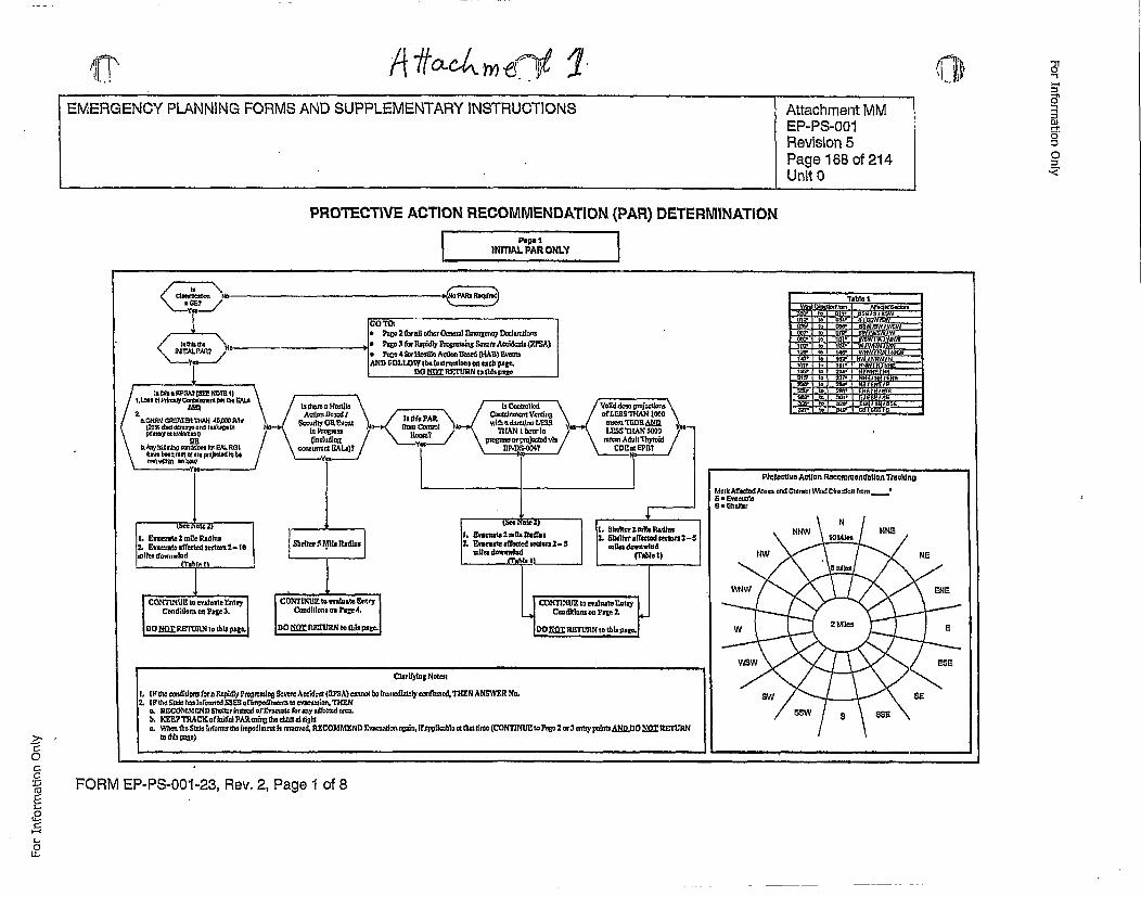
irv Arrefl~ I 1i ~110~1
=~1~
Di
0
PROTECTIVE ACTION RECOMMENDATION (PAR) DETERMINATIONPg INITIAl. PAR ONLY
"rlble &
Pirnccilw Aclln Recovmmendation Trag)lJng
Mer lctc• . arnf Cimani W, Dfr,,onfrom rm __2 • vamrn?U * hdl
I• C'ari~ytzzg No~et
I tbe~ cesltldons fore Rnjtldy Progiodn Severn Acciden (RPSA) cee be • tem o utm~~cafetd, ThEN ANSWER No.2. I• •o~et hm [nfmoendS•.SE ofmpedhmUcne t io.,TU"EP(
o. RECOMME•N D 21o'ht•PHn or •'ees•rote fO!y a ffbed ems
o. Wbenth do Stol !ut'arms the Impedlmeert I r,'moved, RE•COMMEND En u ed r •nReplirebloe ,d etlett(CONTNU• Pago2 ct3 ypetts•D.O • ETRZ
FORM EP-PS-O01-23, Rev. 2, Page 1 of 8
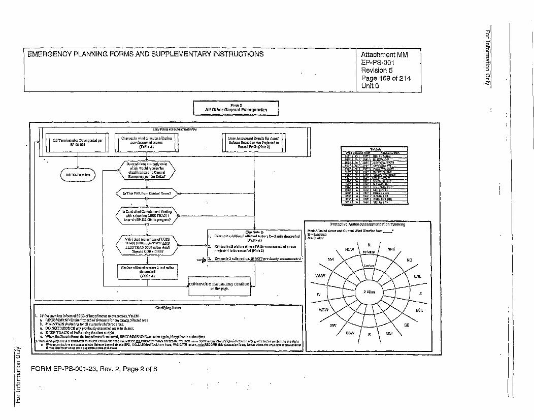
-n
EMERGENCY PLANNING FORMS AND SUPPLEMENTARY INSTRUCTlONS Attachment MMEP-PS-00O 1
Revision 5Page 169 of 214 0
Unit 0 •
Pa0e 2
All Other General Emergencies
-I G emntdo onrddpr Chrnttos to ywl ot dert~on ey•ciAor Dose AesemsrenteR.lt E ott o AtrsootOt emnsdrOw~ee ~now downwind sectors Rtelesco Et~ceod or Am Projected to
EP-0O-002 (Toble A) Itocced PA~e (Note 2) iTt-
',Mad Do condilFeo, coweotty eotot..h.... . Iwo0 . ... ol s£1e78the
.2' 14e 000 W0 1 I0N5
/Io Controltled Coololnmeot Ventingts \tth o dutottoo LE3SS THAN', I No-.
troonryin Etc-DS.0O4 en romrs' Pr0/toAle eerre/~o tsko
"('¢€ o~el)Mark Afftletd Ateas 000 Current WMed Otroetle from -// e~ddsepojcdnsoLGSt.I !tVocootme ddtttootnnlredled secors 2-5sottledowonwtod soF.,hlt-r
'•yroid ~ ~~CDIo ttEyt /pojstt t •€ec~dotNoee),o Nt N
t. I F theottte .Jol lo9nomied SEES ott~mpodtmroto to Oooeutinon TIelrNt
o, RtICOMMP.ND -thttnrlontoead ot Rvoeuotc te rorny t•wIv effected oweb. MAl NTA lN ohotterdoot oret correottytio Ttered ereno. 8c,. DtO £OT REDUCE- soy proviossily vtetr¢eted coins to hshlher.0, KEEP "reACK ofPAttPw,- ton•Ie etros ot rihtt te.. VWdtoco the 5to,0o titnors ttoeimpeditment is removed, RE•COMM END Enacuoteon e0te], Itoyptlicoble or thint time
2. 'J out deco peolocito, otf O•.At"tI£Rtt Du O'OUAI.TO ",O0 ~mcm T:OttS l..GOA0tnOF T R5"WANOR .*rD 000•0 r~S5ttt mrcm Chtts'Thyeoid COR to coy etoco sectorton chor to rttnetthec.. O PF eeo prolocuteno aem oxceodod oto• duetecee b 0yond to n,11, OPZ, OOLLtIAOCATe wlthr 10 S~totoVAttOATlO 000 u0, OjdD.RECe~OCMMN E',oee0cton to• ,nyttoctent rter•o ¶10PAtS 00000000 tonomot
0 n•odIn tcromnntectler doo too~letton ]I [IeI timn AG,
• FORM EP-PS-0O1-23, Rev. 2, Page 2 of 8
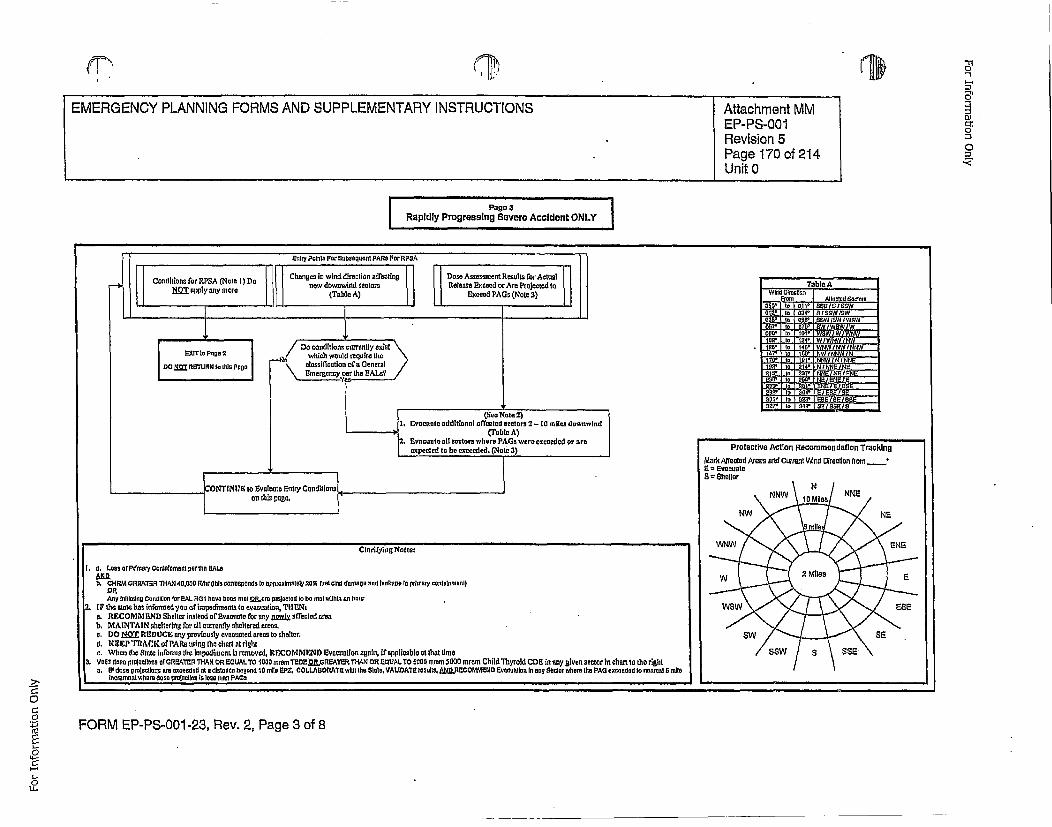
LI®EMERGENCY PLANNING FORMS AND SUPPLEMENTARY INSTRUCTIONS Attachment MM
EP-PS-0O01Revision 5Page 170 of 214Unit 0
Co
0
,=
J J J I I I lib
Pago 1Conditions f[or RPSA (Note I) Do Clnsnnslot i wind. directnon affct0ing
"I NO epply sny mere now downwind stotors
DoTo abiloocrety exi)
'TsbioAWild Qireotion
From Attnotooo000toto300' to oni, snolOIO0WIto' to oa~ else isON' to 000' 00W0011500w00 to OW oWl 0018W080' to 00' WOWIW WOW
0' to 24' 01/01001105* to 40' 010 WANOW
047' to ¶01' IN IO'o I NE
102' to 4' N N I N0' 0 03 N El ElEN
000' tO 059' NOIONOI00' to 00' 0 0801000
000' 004' 20 003 50 to 020' 00/00/007' to 040' 001002 0
Clo ril'yitg Nnolos
I. a. Loseas of meo yeoltoomnot potttta EAtLsto, CHRMGRFO•TER-OHAN 40.0 F• R (lioN nresoonods[toap~l~trtontotay 2501 uncod dertlesoand tokos srntpry Wcntarenoao)
Any tllootleogo Cornoido for 000. lOGO thve Noonl mr O.at GEo prmooated to No 01st withi• n ]oouot.It thoootolsm ho• inofooned yot of itpoditunoto to nvaoooatno., TIt No
to. R1ICOMM END) Shatter lnotend of Eversooto for tony j.os.[v afteoted sinsb. MAINTAIN shneltering for oll nourretly olhelterod ar~ss,o, D0O(Sl REDUCE any proviosly evonos~ted oman to oholtor.A. KEEP TRACK of PARs toning its heotnt ot righta. Whin h ttn tte informs tlotompoditmotL sromo~vod, RECOMMEND lvoontio snia, nf pplicoblott~hot tint
3.Votit dnen prolocgono of GRSATEt 'THIAN OR ECLUAL TO 1000 trefr=T0EnE ORGR5ATER THAN 0OR EGUAL TO 0000 nirom 3000 omroo Child Thyroid CDB in any g|von scotore it char to the righta. IFo dose peeletnsorfon exenended st e distooto Noeyond 10 mile EPZ COLLABOROATEwi•It tho Stttn. VAtLtATE requlite W.RECOMMEOID vEnonotion t ont aetSor where (No PAG exceededO 00 nenrest SmriteI tocmrenntvtmlanhe pnOOO riaton to tosa thon PAGe
FORM EP-PS-O01 -23, Rev. 2, Page 3 of 8
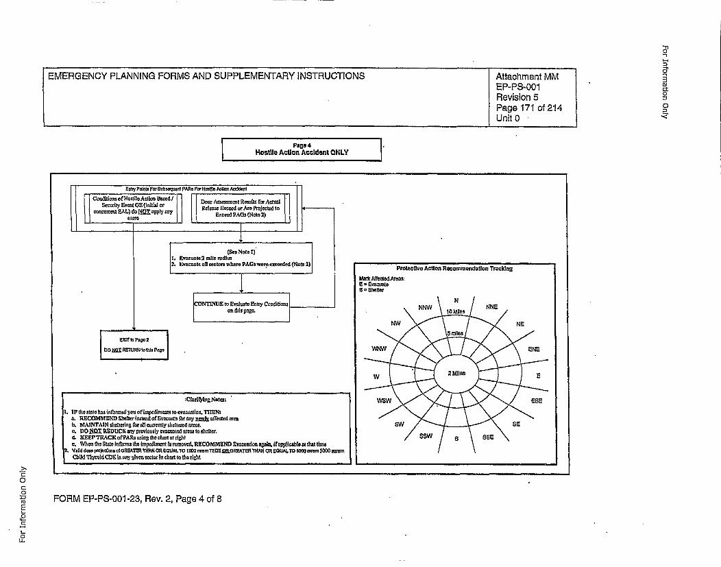
-n
-3O-
0_.,,<
I ~Page 4Hostile Action~ Accident ON, LY
0-0
4-
L.
,0
FORM EP-PS-001 -23, Rev. 2, Page 4 of 8
For Information Only
(9'1 7/114)
'-- Developer InsirtzcffonThis page provides a template for anapp~roval chain process. Licensees may useanothr established approval process forthis document; including those used forp~rocedures or emergency pl1an review andapproval.
Approved: Stan Davis (Site E.P Manaer)"
:Approved: _DE/.IVA (oRo)
Approved: _PEMA____________________ (oRo)
Approved: (ORO)
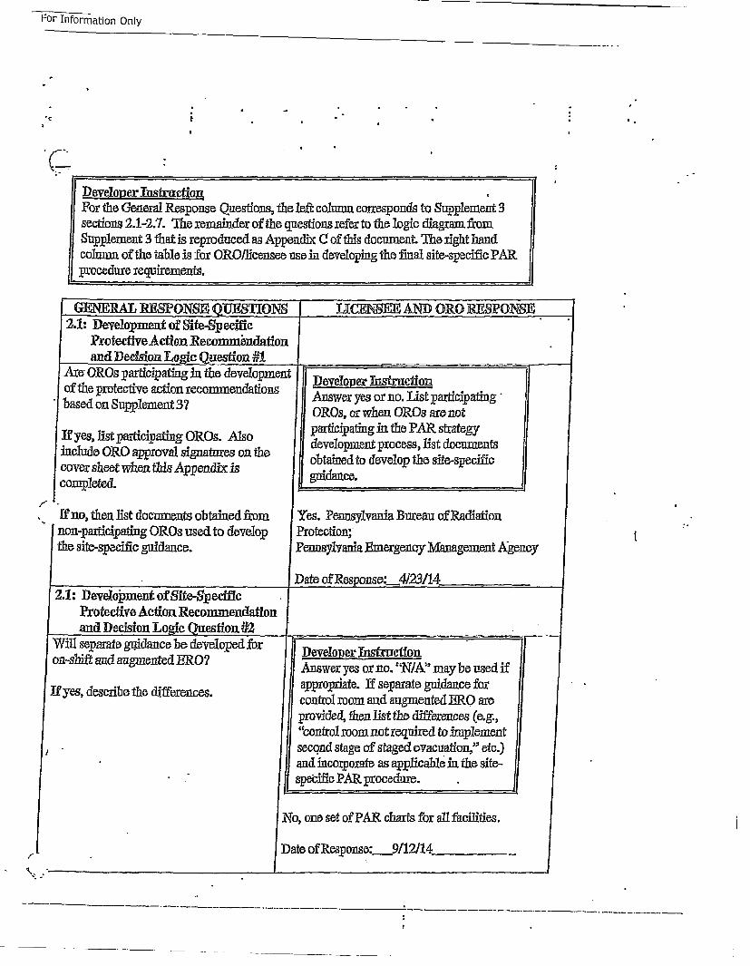
For Information Only
For Information
Only
Developer ThstmctionFor the General Response Questions, the left column corresponds to Supplement Ssections 2.1-2.7. The iemainder of the questions refer to the logic diagram fr~omSupplementS3 that is reproduced as Appendix (! of this document. The right handcolunm of the table is fox ORO/licensee use in developing the final site-specife PAR.procedure requirements.
GENERlAL RESPONSE QUIESIONS DtCENSE ANT) ORO RESPONSE -
2.1: Development of Site-SpeecicProtective Action •Recormm~ndationand Decision Logc. Question #1 ._____________
_Amx OROs participating in the development Developer Xnstructionof the p~rotective action recommendations orn.Lspaicatg
-based on Supllement 37 ores, or when oreOs are not
If yes, list participating OROs. A~s participating int the PAR strategyinclde RO pproal ignture onthe development process, list documents
cover sheet when tbis Appendix is obtindatn evlp h it-pei.completed.
[f no, then list documents obtained from Yes. Pennsylvania Bureau of Radiationnon-pgarticipating ORes used to develop Protection;the site.-specific guidance. Pennsylvania Emergenoy Management Agency
Date of Response:__4/23/14_______
I-
t
I2.1: Development of Site-$pecifcieProtective Action Recommendation Ion-si
If yes
!r
zift and augmented ERO?
•, describe the differences.
Developer Instrut~cionAnswer yes or no. "NIA" may be used ifappropriate. If separate guidance forcontrol room and augmiented ERO areprovided, then Just the differences (e.g.,"control room not reqluired to implementsecond stage of staged evacuation," etc.)and incorpoerate as applicable in the site-spe'ciflc PAR, 3procedure.
INo, oneo set of PAR charts for all facilities.Date of Resp~onse: 911:2/14
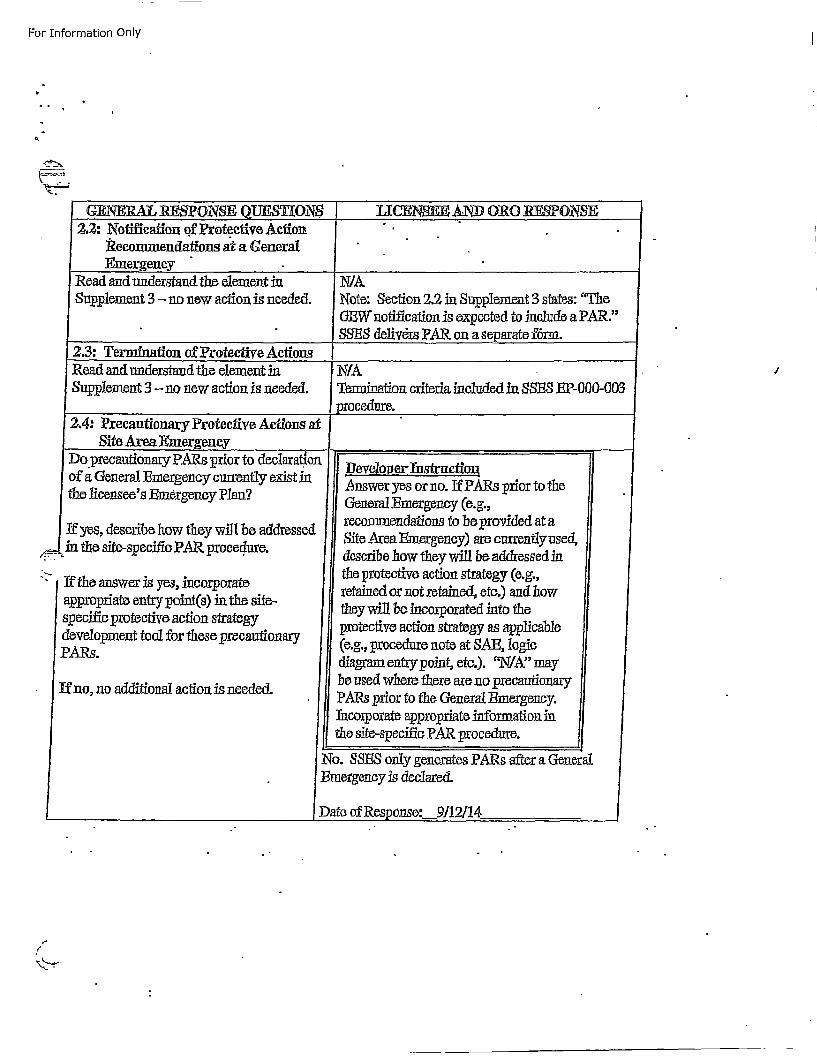
For Information Only
GENERIAI RESPONSJE QUES¶ON$ 1 ICeNSeE .AND 0R0 1F~E-PONSE
Recommendations at a General
Read and understand the element in N/ASupplement 3 -no new action is needed. Note: Section 2.2 in Supplement 3 states: "The
0BW notification is expected to include a PAR."SSES delivers PAR on a separate fdnn.
Site Area J•me~rgeneY ..______________
I~o precautionary k'AaX, prior to cleciarattorof a General Emergency currently exist finthe licensee's Emergency Plan?
Ifyes, describe how they will be addressedin the site-specifi PAR procedure.
""If the answer is yes, incorporateappropriate entry point(s) fin the site-specific [protective action strategydevelopment tool for these precautionaryPARs.
If no, no additional action is needed.
i Ulevelop.er. nstructionAnswer yes or no. If PARs prior to theGeneraLEmergency (e.g.,recommendations to be provided at aSite Area Emergency) are currently used,describe how they will be addressed inthe protective action strategy (e.g.,retained or not retained!, etc.) and howthey will 1,e incorporated into theprotective action strategy as applicable(e.g., procedure note at SAE, logicdiagram entrypoint, etc.). 'Rt41A"' maybe used where there are no precautionaryPA~s prior to the General Emergency.Theorporate appropriate information inthe site-specific PAR procedure.
No. 88S__, only generates PARs after a General•mergency is declarec.
Date of Response: 9112114
i
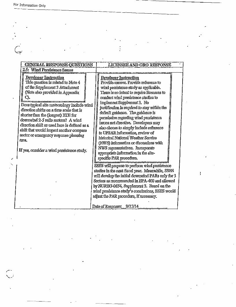
For Information Only
C-
GFENERA]5 RESPONSE QUESTIONS LXCJRNSEE AND ORO RESPNSE
S.5 W. esee su....Devlop~er Thsfruction Doveleper usirction
This question is related to N'ote 4 Provide answer. Provide reference toof the Supplement 3 Attachment wind p~ersistence study as applicable.(Note also provided in Appendix There is no intent to require licensees to
SC). ,conduct wind persistence studies toDoes typical site meteorology include wind implement Supplement 3,. No
slii'tsn atimescae tiarjustificationis required to stay within thediretio • n atim scle hat s dfau• gidace.Theguidance is
downwind 2-5 mile sectors? A wind periussive regarding wind persistencedirection shift as used here is deolue as a issues not directive. Developeors mayshf tha wol"matanteops also choose to simply include referencesector or emergency response planning to UPSAR information, review of
area, historical National Weather Servicearea. ('NWSf) information, or discussions with
if yes, consider awd estucsty. NW,5 representatives, Thcorporatea wid prsitenc stdy. approp~riate information in the site-
, ~Sp~ecii~o PAR procedure.
• SSBS willpropose to perform wind pei:sistencostudies in the next flscal year. Meanwhile, •SSBwill develop the initial downwind PA~s only for 3Sectors as recommended in BI'A-400 and allowedbyNURBG.-0654, Supplement 3. Based on thewind poersistence study's conclusions, SSBS would.adjust the PAR procedure, if necessary.
Date of Res onse:._9/1!711i4
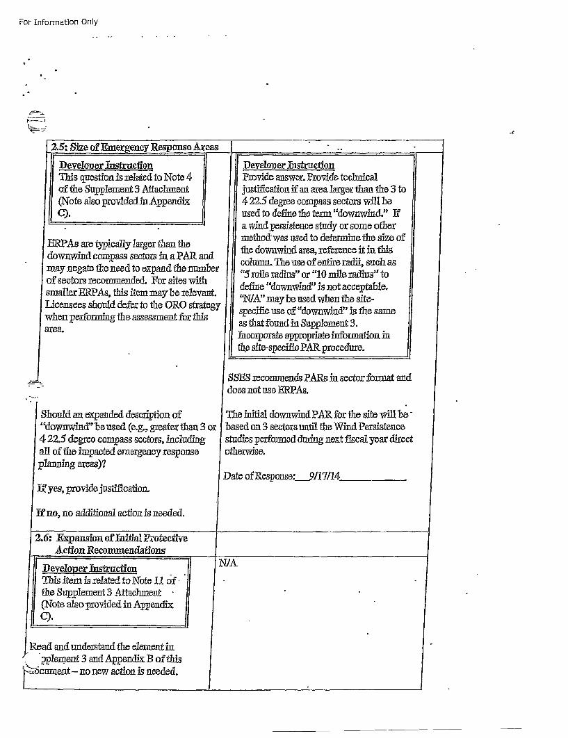
For Information Only
I2.5:5 siz of Emergency Response Axeas
I-:-,-
Developer IntrctionThis question is retated to Note 4
of the Supplement 3 Attachment
(Note also provided in AppendixI
ERPAs are typically larger than thedownwind compass sectors in a PAR andmay negate the need to expand the numlberof sectors recommended. For sites withsmaller ERPAs, thifs item may"be relevant.Licensees should defer to the ORG strategywhen performing the assessment for thifsarea.
Develoyer Th etrutonProvide answer. Provide technficaljustification if an area larger than the 3 to4 22.5 degree compass sectors will beused to define the terra "downwind." Ifa wind 3persistence study or some othermethod was used to determine t~he size ofthe downwind area, reference it in thiscolumn. The use of entire radii, such as"r5 mifle radius" or "10 mile radius'" todefine "downwind" is not acceptable.c'N/A" may be used when the site-speci~fic use of "downwind" is the sameas that found inSupplement 3..licorporate appropriate inform ation inthe site-specific PAR procedure.
58135 recommends PARs in sector formait anddoes not use ERPAs.
The infitial downwind PAR for the site will be -based on 3 sectors utfil the Wind Persistencestudies perfonned durig next fiscal year directotherwise.
Date of Responso: __g /I l4.
I
m
Should an expanded description of"downwind" be used (e.g., greater than 34 22.5 degree compass sectors, includingall of the impacted emergency responseplanning areas)?
Wf yes, provide justif ication,
If no, no additional action is needed.
or
- 2.o6: Expanson of luitial ProtectivAction Recommendations
Developer Instrnction N /AI hsitem is related to Note !1 of "the Supplement 3 Attachment(Note aloprovided in App~endix
Readl and under~stand the element inpplement 3 and Appendix B of this
i ocmnent- no new action is needed.
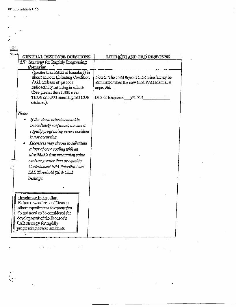
For Information Only
"- G:ENErAL RSONSE Q•hSflONS
AGI, Release of gaseousradioactiviy resulting iln offsite* dose greater than 1,000 mrein
*ThBD or 5,000 trero iyyoidcDW"declared).
S LICENSEE AND ORO JE•PONSE
ik.
_
JFN~ote 3: Thle child thyroid ODE criteria may beeliminated when the new EPA PAG Manual iaipproved.
Date of Response: 9117/14
No-
I\
~e~s
oIf the above criteria cannot beimmediately confirmed, assume a
rapidly progressing severe accident
iv not occurring.
Z Lcensees may chwooe to substitutea loss of core cooling with an
identifab le instrumentation .valtesuch as greater than or eqtazl to ]
Containment ER Potential LossEAL Threshold (20% Clad
ii
Damage.
iDeveloper ThstruetoniEFxtreme weather conditions or:other fimtediments to evacuationdo not need to be considered fordevelopoment of the licensee'sPAR. strategy for rapidl~yp~rogressing severe accidents.
lk
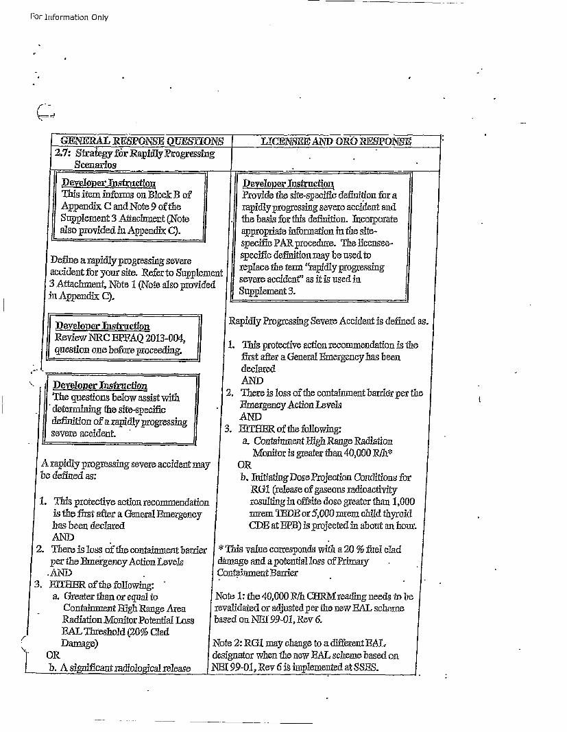
For- Information Only
2.7: Strategy for Rapidly Progressing_ Scenarios
SDevelop er ThstrnuctionSThis item inforns on Block B of
Ap~pendix C and Note 9 of the| ujpplement 3 Attachment ('Note ISalso provded in Appendix C).
SDefino a rapidly progressing severeSaccident for your site. Refer to supplement13 Attachment, Nbte 1 (Note also providedinAppendix Q).llt Developer Thst~ction- 11! Review NRC ]3PAQ 20 13-004, if
que stion one before proceedin.g, i
"- iiDeveoloper ThfrctionThe questions below assist withIF determining the site-specificde~fntion of a rapidly progressingsevere accident.
A rapidly progreossing severe accident maybe defined as:
1. This protective action recommendationis the first after a. General Emergencyhas been declaredlAN)
2. There is loss of the containment barrierper the .Thneigenoy Action Levels.
.AN~D3. EITTER of the following:
a. Grreater than or equal to_ Containment high Range Area
Radiation M~onitor Potential LossF AL Threshold (20% CladDamage)
OR
b. A significant radiological release ]
SDeveloper InstructionProvide the site-specific defintif.on for arapidlyprogressing severe accident andthe basis for this definition. Incorporateappropriate information in the site-specific PAR procedure. The licensee-specifie definition may be used toreplace the term "~rapidl~y progressingsevere accident" as it is used inSupplement 3.
SRapidly Progressing Severe Accident is defined as.
1. This protective action recommendation is theS first after a General .Emergency has been
declaredAND
2. There is loss of the containment hardier per theEm~ergency Action LevelsAND
3. IEITBER of the following:a. Containment !High Range Radiation
Monitor is greater than 40,000 R/h*~ORb, Thitiating Dose Projection Conditions for
RG1 (release of gaseous radioactivityre~sulting in offsite dose greater than 1,000rnrem TEDE or 5,0200 narem child thyroidCDB at EPB) is projected in about an hour.
This value corresponds with a 20 % fuel cladunage and a potenthia loss of PimrDen. in2ment Barrier
)te 1: the 40,000 R/h CURM reading needs to hevraidated or adjusted per the new RAL schemesed on NE1i99-01, Rev 6.
'te 2: RG1 may change to a different EAL•ignator when the new B•AL scheme based on]t 99-01, Rev 6 is implemented at SSFS.
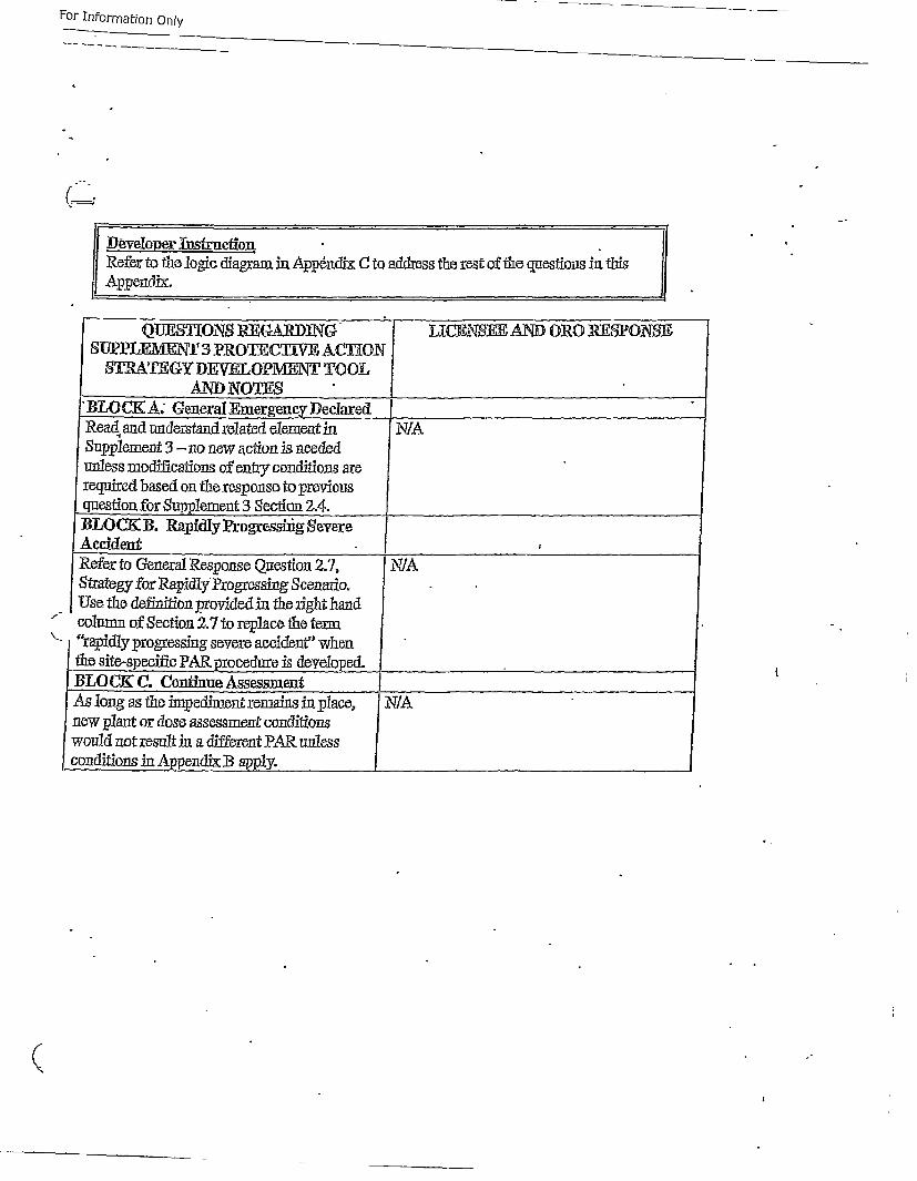
For Information Only
II ,I)•va°Per lustruc•°n •II Refez m t•o logic diagram in Appendix C to address the zest of tb• questions ia thisl! Ap£endix.
QUS.8IONLS RPa-AJRDJNC•-
SUPLE1VENT :3 PR.OTECTIE ACTIONS•hATECY DhIWEOPMENT TOOL
AND NO•S"BLOCK. A; Genteral Emergency D~eclaredRead and under~aa~d related element in
Refers todiefealtesonse Q esycodtions 2.7
Use tfe definition prvied iepns the lrighthancoestion ofo Supetin27to replcethen te.4.'BrOpid .progressing severe accidentwhren
ALCKC.iCont ine ssmnAselngea the i,-e dient re maionse Qsin p2ac, N 1newtpanteg or apdoye agsessment cndarions
wol nrpd~potresulting asdferen PaRciuntwesn
conditions in Appendix B3 apply.
7LICENffE AND 01R0 lESPOgN~
NIA
I
i
r
i
IA
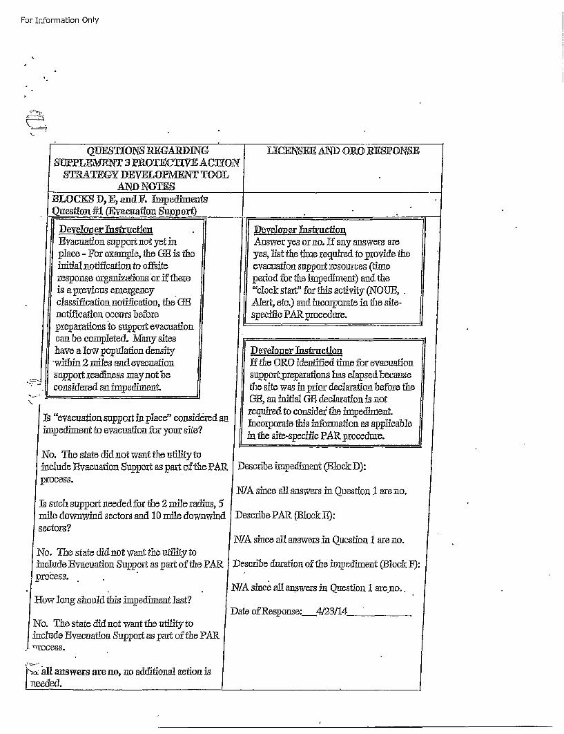
For Information Only
QUESTIONS REGARDIN( [ LICENSEE AND OZRO EES:PONSE
•Question #1 •vacuafion Supp~ort) _________________
I
Deyeloper Instruction.. Developoer ThsfrucitionEvacuation support not yet in Answer yes or no. If any answers areplace - ffor example, the GE is the yes, list the time required to provide theinitial notification to offsite evacuation support resources (timeresponse organizations or if there! period for the impediment) and the
is a previous emergency "clock start" for this activity (NOUB,.classifcation notification, the GE Alert, etc.) and incorporate in the site-notification occurs befor:e specific PAR procedure.preparations to sulpport evacuationcan be completed. M~any siteshave a low population density iDeveloper Instrction
"within 2 m~iles and evacuation if tile ORO identified time for evacuationsupport readiness may not be support.preparations tins elapsed becauseconsideedanimedmet.te site was in prior declaration before the
- I GE, an initial GE declaration is not
Is "vacatin supor inplae" cnsi~re an required to consider the impediment.Is rd an Incorporate this information as applicableimpediment to evacuation for your site? in the site-specific PAR. procedure.
No. Thle state did not want the utility toinclude Evacuation Support as part of the PAR Describe impediment (Block D):
process.N/A since all answers in Question 1. are no.
J] suhspotnee or the 2 mile radius, 5mile downwind sectors and 10 mile downwind | Describe PAR, (Bl1ock B,):
sectors?N/A since all answers in Question 1 are no.
No. The state did not want the utility toinclude Evacuation Support as part of the PAR Descrb duration of the impediment (Block 19:process.
N/A since all ans.wers inl Question 1 are no..how long should tins impediment last?
Date of Response: 4123/14N'o. The state did not want the utility to•nclude Evacuation Support as part of the PAR_.-rocess"
•, all answers are 110, no additional action is.eeded.
iJ
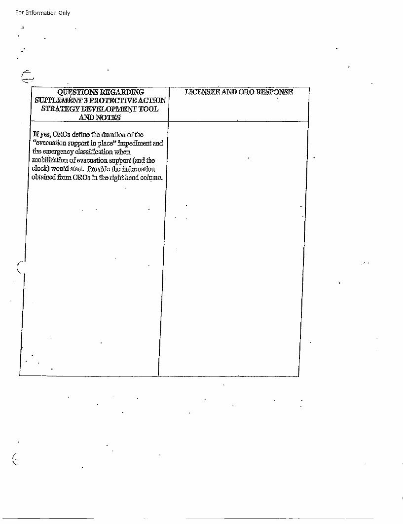
For Information Only
QUPPLEM NT 3 PROTECTING ACTGNEEAN IONSON]SUPPEA~T 3 2RVOTICTWIT CT[OO
ADNOTES __ _ _ _ _ _ _ _ _ _
If yes, OXROs defuae the duration of the"evacuation support in •place" im~pediment andthe emergency c~assi~cation whet,miobili'ation of evacuation support (and theclock) would start. Provide the i~nfonnationobtained from OROs in the right hand column.
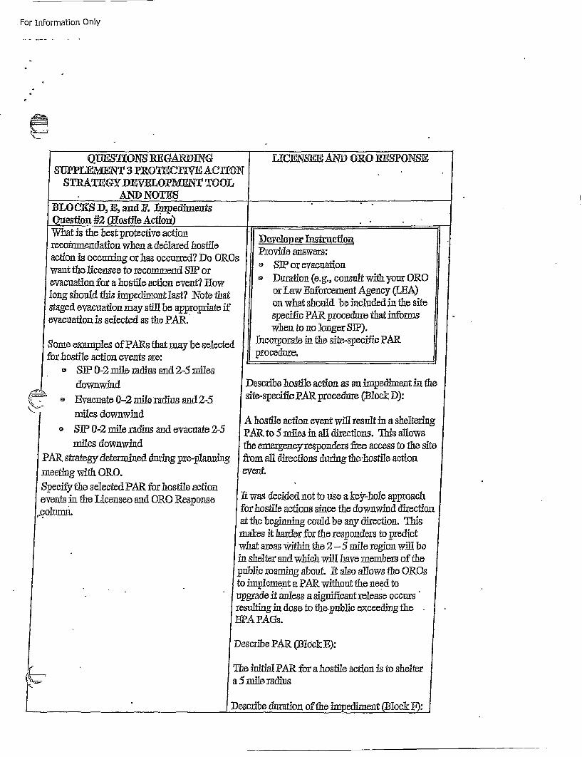
For Information Only
S•PPIEMEN] 3 PROLThEIV ACITIONISTRATEGY DEVELOPM•NT TOOL
LICENSEFEAND O1WROESPONSE
IBO KD,E adF. IQuestion #2 (ifostile Acfhc
What is the best protective actionrecoimnendation when. a de6lared lvstileaction is occuning or has occurred? Do ORCwant the licensee to recommend SIP: orevacuation for a hostile action event? Howlong should this impedinient last? Note thatstaged evacuation may still be appropriate ifevacuation is selected as the PAR.
Some examples of PARs that may be selectedfor hostile action events are:
,,SIP 0-2 mile radius and 2-5 milesdownwind
e'Z- o -vacuate 0-2 mile radius and 2-5
miles downwindS SIP 0-2 mile radius and evacuate 2-5
miles downwinmdPAR, strategy' determined dining pre-p~lannigmeetinug with. ORO.Specify the selected PAR for hostile actionevents in the Licensee and orO Response
1.column.
F.
3s
f
,Develop er InstructionProvide answers:r 'SIP or evacuation
oDuration (e.g., consult with your OROor Law Thnforcement Agency (LBA)on what should be included in the sitespecific PAR, procedure that infonmswhen to no longer SIP).
flacorporate in the site-specific PARprocedure.
SDescribe hostile action as an inpediment in the
site-specifi PAR procedure (-Block D):
A hostie action event will result in a shelteringPAR to 5 miles in all directions. This allowsthe emergencyresponders free access to the sitefrom all directions during the-hostile actionevent.
It was decided not to use a ke~r-hole approachfor hostile actions since the downwind directionat the beginning could be any direction. Thisnakes it harder for the responders to predictvhat areas within the 2- 5 mfile region will be'a shelter and which will have members of theublic roaming about. It also allows the erosimflplement a PAR without the needA to
tpgrade it unless a signi~ficant release occurs"•sulting in dose to the.public exceeding theIPA PA~ts.
escribe PAR (-/lock 13):
ie initial PAR for a hostile action is to sheltermil•e radius
•scribe duration of the inapediment (Block F):z L •
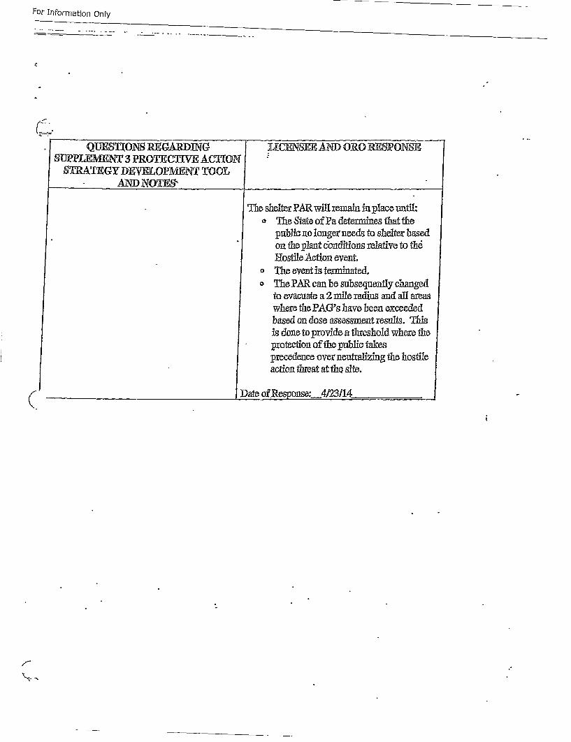
For InFormation Only
For Information Only
Q•TJElONS Rl GATRD]NSUPPLEMENT 3 PROTECTWIV' A.CThI
S¶RATEGY DEV-ELOPMENT TOOLAND NOTE'.
C
IfJIRSEE AND O1(0 RESPONSE
T he shelter PAR will reinui in place until:o The State of Pa determines that thepublic no longer needs to shelter based
• on the plant cobnditions relative to t•dHostile :Action event.
o The event is terminated,o TheoPAR can be subsequently changed
to evacuate a 2 mile radius and all areaswhere the PAG's have been exceededbased on dose assessment results. Tiis done to provide a threshold where theprotection of the public takes
S precedence over neutralizing the hostile
action threat at the site.
Date of.Response:.__4123114.
r
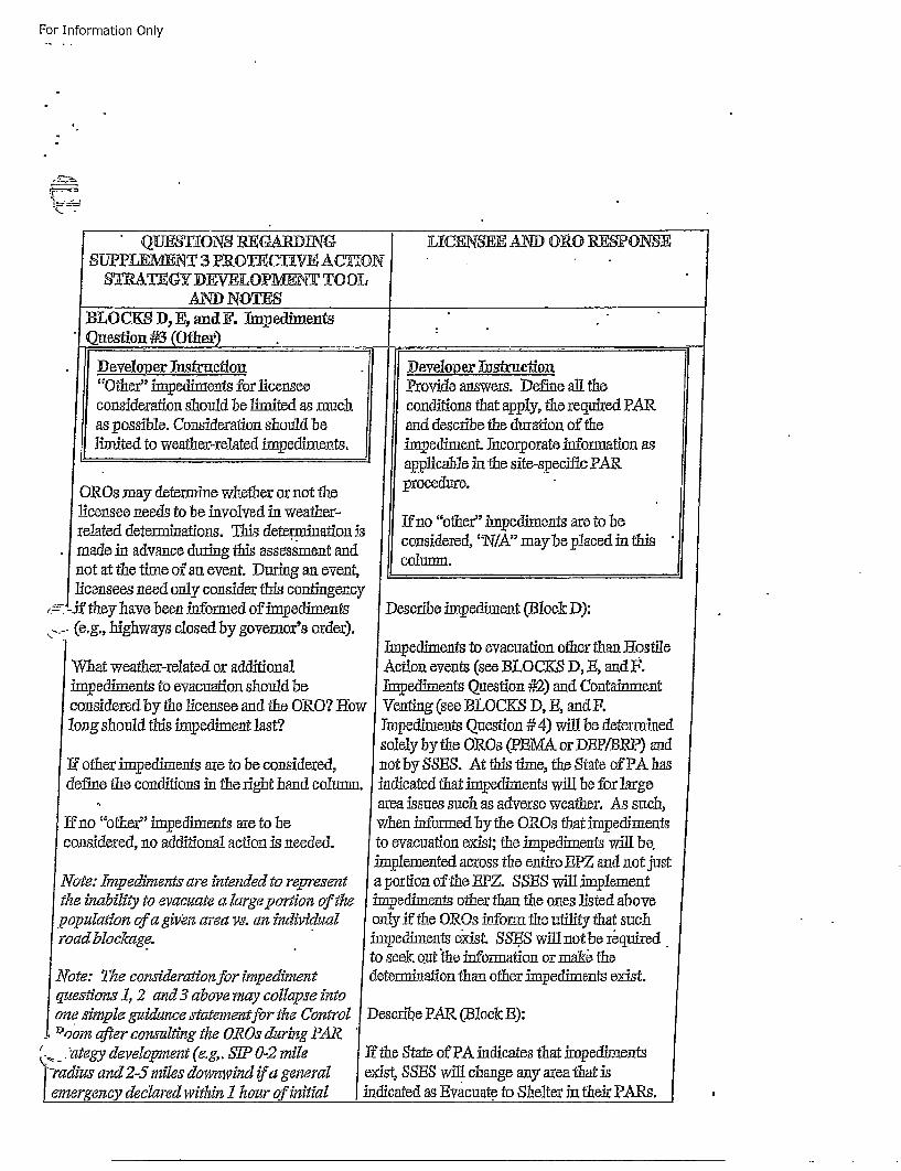
For Information Only
QTJES'IUONS RUGARDTN(9 L][CENISEB AND) ORG RESONSESU-PILEMENT 3 PROINCTWEN ACTHONr
WAIEY D.NVELOPMENT TO OLAND) NOTES
BLOCKS D, E, and]?. Impediments*Question #3 (Othier)
* Deeoper Inflaction Developer Iust ruction"Other" impediments for licens•ee[ Provide answers. Define all theconsideration should be limited as much conditions that apply, the required PARas possible. Consideration should be and describe the duration of thelimited to weather-relatedl impediments. imp~ediment. Incorporate information as
applicable in the site-sipec~ifi PARORes may determine whether or not the procedure.
licensee needs to be involved in weather-. fn"ohrimemntaetobrelated determinations. This determiiination 'J cniees~A ab pae nti
*made in advance during this assessment and cniee,'I"myepae ntinot at the time of an event. Durig an event, -_ounlicensees need only consider this contingency
, -. the have been informed oflinpediments Describe impediment (Block D):... (e.g., highways closed by governor's order).
Impediments to evacuation other than BostileWhat weather-reated or additional Action events (see BLOCK.S D, B, andU.impediments to evacuaton should be Impediments Question #2) and Containmentconsidered by the licensee and the ore? how Venting (see BLOCKS D, 1B, and Ulong should this impediment last? Impediments Question # 4) will be determined
solely by the OROs (PBMA or DiRP/BRP) and•If other imp~ediments are to be considered, not by SSBS. At this time, the State of PAk has
define the conditions in the right hand coun. indicated that impediments will be for large, area issues such as adverse weather. As such,
If no "other" impediments are to be when informed by the OROs that impgediments[
considered, no additional action is needed, to evacuation exist; the impediments will be,imjplemented across the entire EPZ and not just
Note: Impediments are intended to represent a portion of the BPZ. SSES will implementthe inability to evacu~ate a large portion of the impediments other than the ones l~isted abovepopulation of a girn area vs. an individual only if the OROs inform the utility that suchroad blockage. impediments exist. SS.ES will not be required.
"to seek o~ut the information or mak theNote: The consideration for impediment determination than other imp~ediments exist.questions 1, 2 and3 above may collapse intoone simple guidance statement for the Control Describe PAR (Block B):
..%'om after consulting the OROs during PAR?*. .'ategy development (e.g,. SIP 0-2 mile If the State of PA indicates that impediments
-radius and 2-5 miles downwind ir a general exist, SSES will change any area that isSemergency declared within 1 hour of initial indicated as Evacuate to Shelter in thleir PARs.
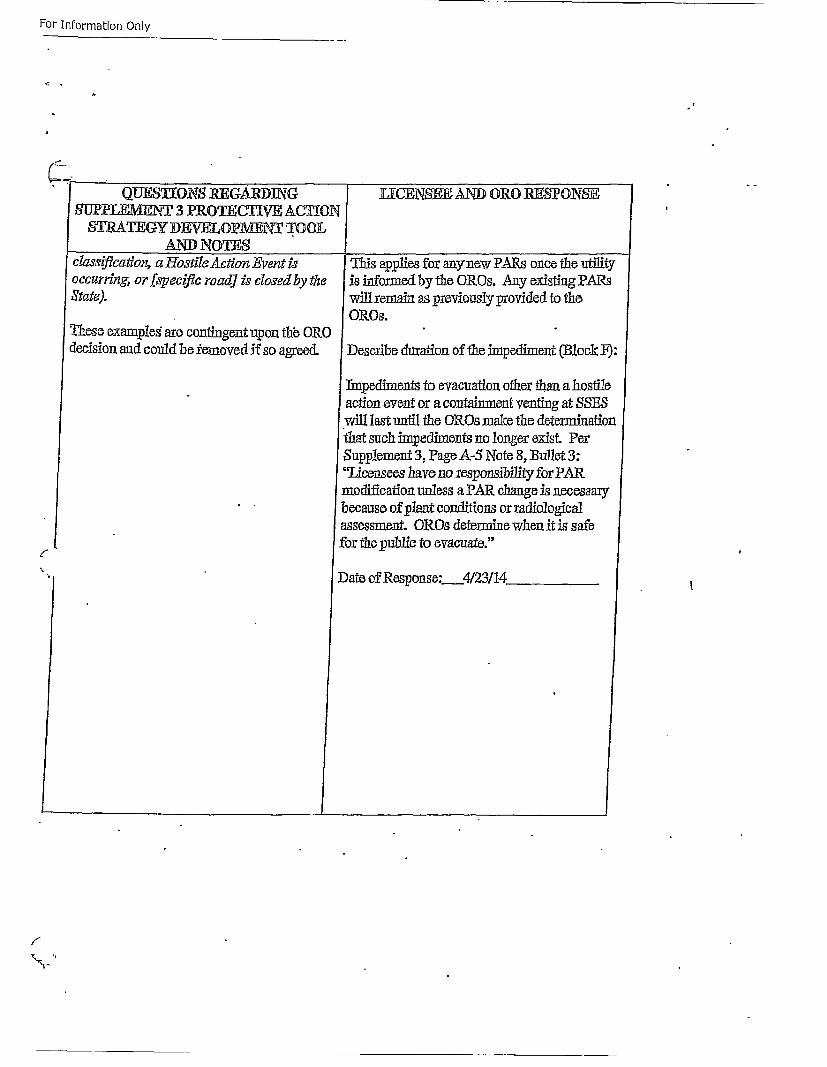
For Information Only
• [ QIJ~ oN8 REGARDING[ U-PLEMVEh7 3 PROTECTIVE ACTI~ONSTLRMTEGY DEVELOPMEN TOOL
ADNOTESclczs4fcatdon, a Hotile A~ton Event ioccurring, or fspecfle road] is cdo~sed by thexState).
These exaaples" are contingent upon thb ORedecision and could be femoved iX so agreed.
6
f •
I EiCENSEE AND ORO RFSPONSE
This applies for anyhnow PARs once the utilityis informed by the ORes. rAny existing PARswill remain as previously provided to theOROs.
SDescribe duration of the impediment (Bl3ock 19:
Thmpediments to evacuation other than a hostileaction event or a containment venting at SSESwill last until the OROs make the determinationthat such im~pediments no longer exist. PerSupplement 3, Page_4.-5 Note 8, Bullet 3:"LiAcensees have no responsibility for PARn2odification unless a PAR change is necessarybecause of plant conditions or radiologicalassessment. ORes determine when it is safefor the public to evacuate."
Date of Response: 4/23/14.

For Information Only
* QLJES•TKONS REGAJRDF.G ULCENS•E AND ORO :R.EON'SE
B1 4OCK• D, Eg, and F. Qulestion #4 (Shlort
rc..
I lDeyveloper Instruction [Developer InstrulctionReview NRC EPFAQ 20!3-004, question Define likely sources of short termtwo before proceeding. releases.
ZW~t: Sortten reea~'e cn ieraion' aply It is recommended that controlled venting•ote Shrt ermrelase onsdertioa aply from containment be identified as a short
only to the azugmened ERO and not to the term release if it is considered amnitigativecontrol room strate~gy, strategy for your reactor type.
Licensee may wish to consider controlled A PAR. of SIP 2-mile radius and 5 moiles
ventng s ashot tnn rleae senaiodownwind, all others monitor and prepareshould be recommended for short termreleases.
Describe venting strategy if used (Block D):
•The SSFS methodology uses the followingstandard for a short term release.
io The release is via a Controlled direct
conainment vent with a duration < 1 ou
o Valid doseprojections > 500 mremThEDS and < 5000 mrem TBDB and < 5000 torero
Adult CDB Thyroid at EPiB*
1" These values may change to align with[current SSES EO~s. In addition, inSc.oiisultation with the State of Pa, the thyoid -
[CTXB criteria may be eliminated when the newEPA PAG Manual is approved.
[These conditions must also be the first PAR] after the declaration of a General EmergencySsince evacuation may already be implementeddue to previously issued PAR's.
. If these conditions are met then the rfrd
I m
r
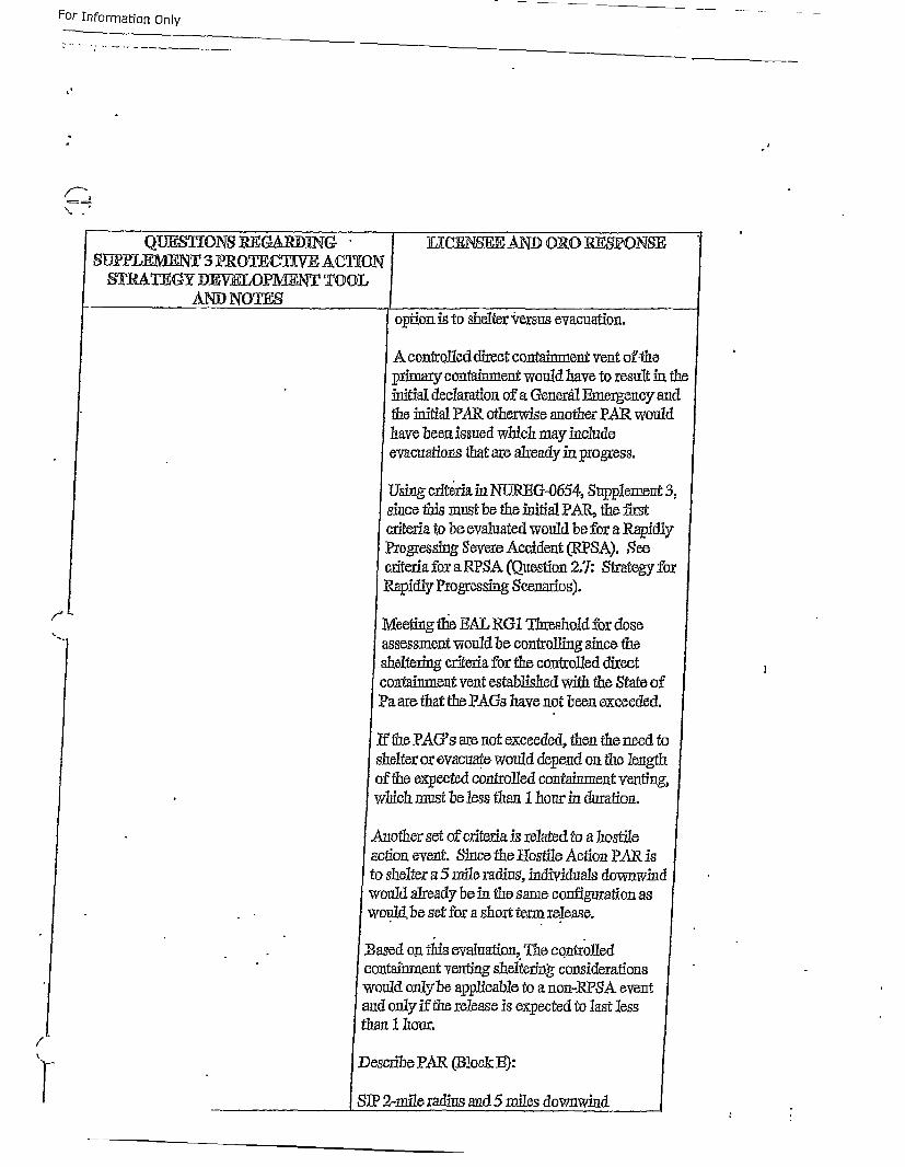
For- Information Only
I
/•
i1
QL3FOtNS REG•ARD]NcG UCEN1 SER AND oRe RESPONSESUPPLEMENTV 3 iPROTECTEVE ACTION
B•I• EGYDEW LOP/J•T TOI• option is to shelter versus evacuation.
A controlled direct containment vent of-theprimary contanment would have to result in theinitial declaration of a Generh1tl Emergency andthe initial PAR otherwise another PAR wouldhave been, issued which may includeevacuations that are already in progress.
Uig criteria in INUIRIG-0654, Supplement 3,sce this must be the initial PAR, the firstcriteria bo be evaluated would be for a RapidlyProgressing Severe Accident (RPSA). Secriteria for a RPSA (Question 2.7: Strategy foxRapidly Progressing Scenarios).
Meeting the HAL RG1 Threshold for dosea~sss•Slnent vould be controlling since the
sheltering criteria for the controlled directconrtainment vent establihed with the State ofPa are that tinePAGs have not been exceeded.
If the PAG's are not exceeded, then the need to/
shelter or evacuate, would depgend on the lengthof the expected controlled containment venting,
whch must be less than 1 hour in duration.
Aother set of criteria is related to a hostileaction event. Since the Ioslile Action PAR isto shelter a 5 mile radius, individuals downwindwould already be in the same configuration aswould.be set for a short term release.
lB sed on thifs evaluation, Theo controlled l
cntainment v•enting sheltering considerations
wuld only be applicable to a non-RPSA eventadonly ifthe release is expected to last lesshan 1 nour.
Desribe PAR (Block B):
SP2-mile radius and 5 miles downwind[
For Information Only
*: ' QUF_•SrhohS RE.ARD1NG. LJCENS ANM ORO RE_•-ONS-EJSLJPPLE1U•N :3 PRoTr~C¶¶VE AGCTION
•ITRA•hGY DEVELOPMENT? TOOL
*Descri1o duration of tho hnredimnent (Block lq-:
Approximately 1 hoi.
Date of Response: 9117114
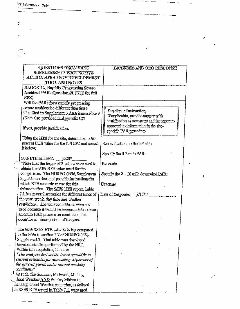
For InFormation Only
(7.
QUESFUONS WG~ARDIN4SUPPLEMNTL'3 PROTETV
ACTION STRATEGY DEVELOIPMENTTOOL AND NOTES I YicEN8K~ AND i/
Accident PA.Rs Question #I (M.FE for flEJZ)
I
IW ill the PARs for aiapidly progressing _ _ _ _ _ _ _ _ _ _ _ _ _ _severe accident be different than those 1Dvle hfutoidentified in Supplement 3 At tachment Note 9 Dapplocaber.srfovdanswrwt
(Ntealo roidd n ppnd~ ") justification as necessary and incorporatefyeprovide justification. fI appropriate info~rmation in h ite
eyesspecific PAkprocedure.
Using the 13T for the site, determine the 90percent ETh value for the futll BPZ and record See evaluation on the left side.it below:.
Specify the 0-2 mile PAR.:90% ETI] faI1IRZ: "2:20*
,•I*Note that the largerof-2 values were used to Evacuate
', obtain the 90% RTg'value used for the .comparison. The NtJREGC-O654, Supplement Specify the 2- 10nmileodowwind PAR:
3,gidace oes not provide instructions forwhich 13Th scenario to use for this Evacuatedetermination. The SS]_5 13Th report, Table7.! has several scenarios for different times of Date of Response: 9115/14the year, week, day time and weatherconditions. The worst conditions were notused because it would be luappropriato to basean entire PAR process on conditions thatoccur for a minor portion of rthe year.
The 90% SSE_,-3Th value is being comparedto the table in section 2.7 of NOREG-Q654,Supplement 3. That tableo was deveOlopedbased[ on studies perforned by the NRC.Within this regulation, it states:"The analysk derived the travel speeda'~fromciurrent estimate• for evacuatiftg .90 percent ofthe general public uinder normal weekdayconditiorLs"A 4s such, thle Suhmmer, Midweek, Midday,
SJoo d Weather AND_.A)D Winter, Midweek,
Midday, Good Weather scenarios, as defined/in. SSES 13Th repop in Table 71, were used..
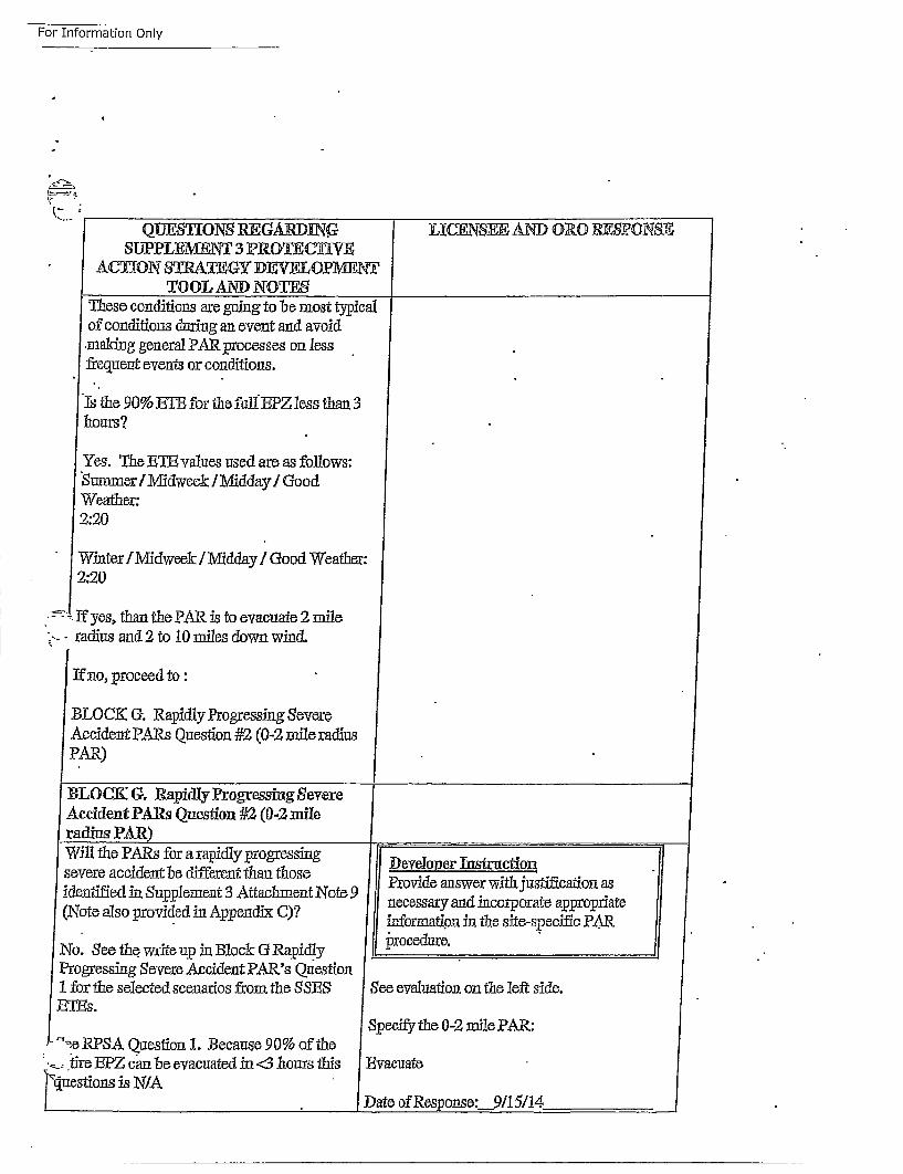
For Information Only
Q1JE6•IONS RIGAIRDQN.SUPPLE1•EN 3 PROThC•h
ACT(ON STRATIEGY DEV•OP1•NTOOI- AND NOT•S
T 1
J
LXCENSEE AND OR0 RESZPONSE
These conditions are going to be most typicof conditions during an event and avoidmaking general PAR processes on lessfrequent events or conditions.
'Is'the 90%E]Tb fr tlie •dEPZ lessth/an 3haours?
Yes. The ETh• values used are as follows:1Summer /Miidweekr / Midday / Goo dWeather:2:20
Winter/Midweek / Midday / Good Weather2:20
• -Tf yes, thanthe PAR is toevacuate 2miles-- radius and 2 to 10 miles down wind.
SIf no, proceed to:
BLOCK (. Rap~idly Progressing SevereAccident PARs Question #2 (0-2 mile radiusPAR)
al
r
!
jtI
I-
BLOCK G,. R'apidly Progressing SevereAccident PARs Question #2 (0-2 mileradius PAR) I
SWill the PARs for a rapidly progressing Developer Instruction
severe accident be different than those Poiease ihjsiiainaidentified in Supplement 3 Attachment Note 9 Poiease ihjsiiaina(Note also provided in Appendix C7 infossrmatind inctheosite-asrpecifi aR
No. See the. write up in Block & Rapidly jrocedure.Progressing Severe Accident PAR.'s Question1for the selected scenarios froni the SSES See evlai nonte left side.
ETiEs.Specify the 0-2 mile PAR:
• 7,SRP,,A Question 1. Because 90% of thetir• e EPZ can be evacuated in <3 liouxs this Evacuate
•4uestions is N/A
Date of Response:__9/1 5!4
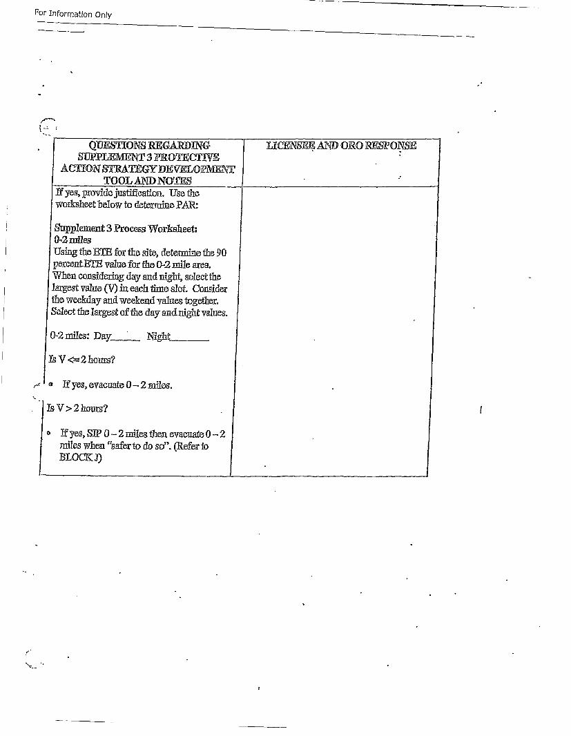
For Information Only
S'•TiIP •MN'T 3 FROTEC1VACTION STRATEGY DEOPMFAT£
TO OL AND NOTESIf yes, :provide justification. U0se theworksheet below to determine PAR:
Supp~lement 3 Process Worksheet:0-2 milesUsing the ETE for the site, determine the 90percent.Th-T value for the 0-2 mile area.When considering day and night, select thelargest value (V) in each time slot. Considerthe weekday and weekend values together.Select the largest of the day and night values.
0-2 miles: Day___ Night
ThYV < 2 hours?
,--o If yes, evacuate0- 2njiles.
Ts V >2hours? /
oIf yes, SJP - 2 mies then evacuate0- 2
miles whaen "safer to do so". (Refer toBLOC-KJ)
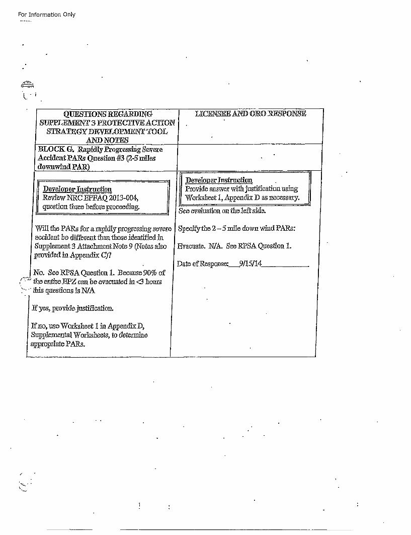
For Information Only
KQUESTIONS R]EGP, IN(G LIL-ENS1_E AND ORO J•SPONSE
SUOPPLEMENT 3 PROTEC1TLVE ACTIONSI1TA¶GY DEVELOPMEN TOOL'
AND NOTE1BLOCK G. Rapidly Progresshig SevereAccdfent PAils Question #3 (2-s milesdownwindl PAR)
I.Developer ThstructionRevibw NRC EPFAQ 2013-004,
Squestion three before proceeding.
Will the PARs for a rapidly progressing soeveaccident be different than those identified inSupplement 3 Attachment Note 9 (N\otes also
Spr~ovided in Appendix C)?
No. See RPSA Question 1. Because 90% of/ - the entire BPZ can be evacuated in <3 hours
:- " s questions is N/A
If yes, providejustification.
Ifno, use Wor~kshaeet 1 in App~endix D,SupIplemental Worksheets, to determineappropriate PARs.
' Pr~ovide answer with justification usingWorksheet 1, Appendix D as necessary.
SSee evaluation on tae leftside.
S peclfytle 2- 5 mile down wind PAis:
Evacuate. N/A. See RPSA Question 1.
Date of Response: 9115114
I
P Ii
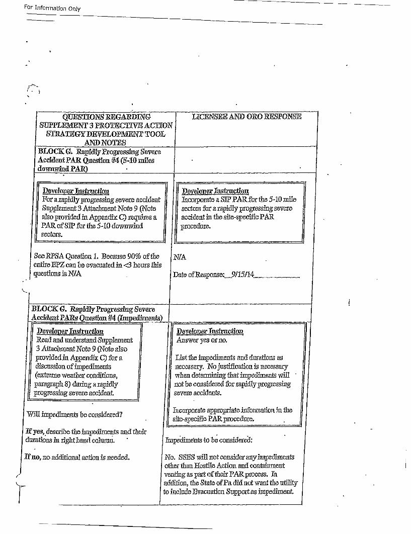
For Information Only
QLJS•ONS R1•GARDING' U-ENSEE AND ORO R,•SONSESUPJPLEMNT 3 PRO¶TClV ACI¶¶ON
6flRATFAGY DEVE•LOJPMEN 1 TOOl,AN]) NO[E•
BLOCK 12-. Rapidly rrogressiug SevereAccident PAR Question #4 (5-10 niiesdownwind PAR)
Developer Intrction IF~or a rapidly progressing severe accidentSupplement 3 Attachment Note 9 (Notealso provided in Appendix C2) requires aPAR of SIP far the 5-10 downwindsectors.
See, RPSA Question 1. Because 90% of theentire BP-Z can he evacuated in <3 hours thisquestions is N/A
Developer InstructionThoorporate a SWP PAR for the 5-10 milesectors for a rapidly progressing severeaccident in the site-spoecific PARp~rocedure.
N/A
LLBLOGL( (. Rapidly Progressing SevereAccdaent PARs Question #4 (fnipedin~ents) ___, _________,______
SDeveloner InstructionSRead and understand Sup~plement3 Attachment Note 9 (Note alsoprovided in Ap0pendix C) for adiscussion of linpedinients(extreme weather conditions,paragraph 8) during a ra~pidlyprogressing severe accident.
t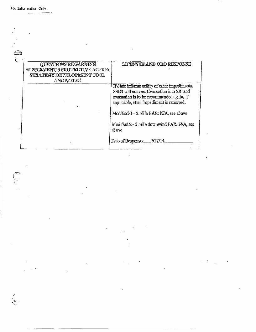
For Information Only
QUEST][ONS REG~ARDING LIGENSEE AND) ORO RESONSE/SUPP•ILEME•NT 3 PRGTEUCTWE ACITON
STRATEGY DEV-ELO•PM/NT ¶TOOLAND NOTES
If State inform utility of other impoedfiments,SSF• will con.vert Evacuation into SIP andovacuatfoni~s to lie recormmended again, ifapplicable, after im~pediment is removed.
Modified 0- 2 nriile PAR: N/A, see above
Modified Z2-.5 m~ile, downwind PAR: N/A, seeabove
Date of Response:___917/14
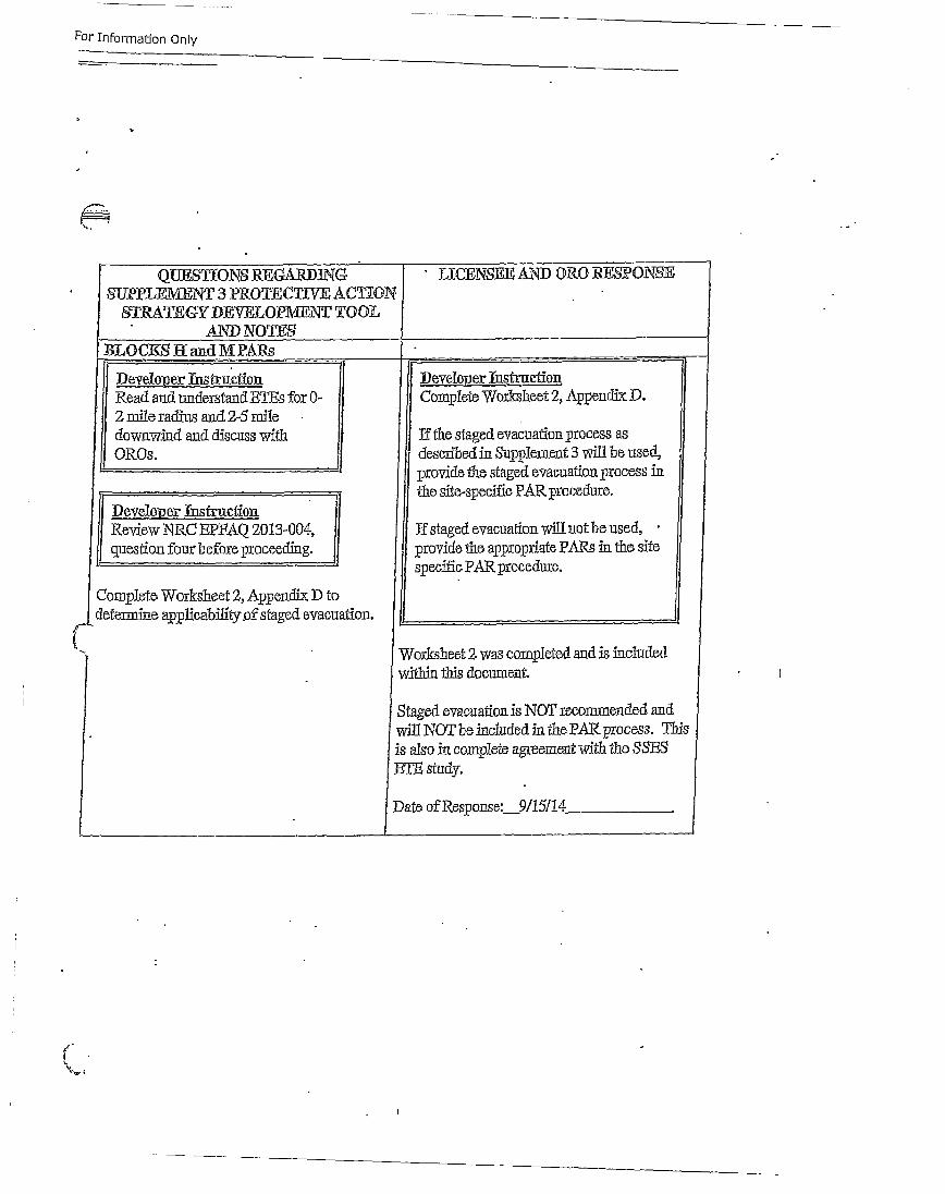
For Information Only
Q1JESIhONS REGARi•IN' LICENSEE AND ORO •E~ONSX
SUPTLF]:ENT 3 rROTECTIVE ACTXONSTRATEGY I)EVELOPMENT TOOL
AND NOThS
BLOCK1S J• audM•fPARs
D).eveIlorner Ths~huctiou Daveloper TtIUstLcfoI
Read anud understand ETEs for 0- Complete Worksheet 2, Appendix P.
2 mile radius and 2-.5 miedownwind and discuss wi~th If the staged evacuation process as
OR•Os. Jdescribed in Supp~lement 3 will be used,
• " 'provide the staged evacuation process in
Devetcuer th-fiznifionPAR, procedure.
Review NRC EPFAQ 2013-004, If staged evacuation will not be used,
question four becfore proceeding. porovide the appropriate PARs in the site
I • specific PAR procedure.
Completo Workshieet 2, Appendix D to
d. ef ermine applicabilit.of staged evacuation.
Worksheet 2. was completed and is included
w~ithin this document.
Staged evacuation is NOT recommended and
(
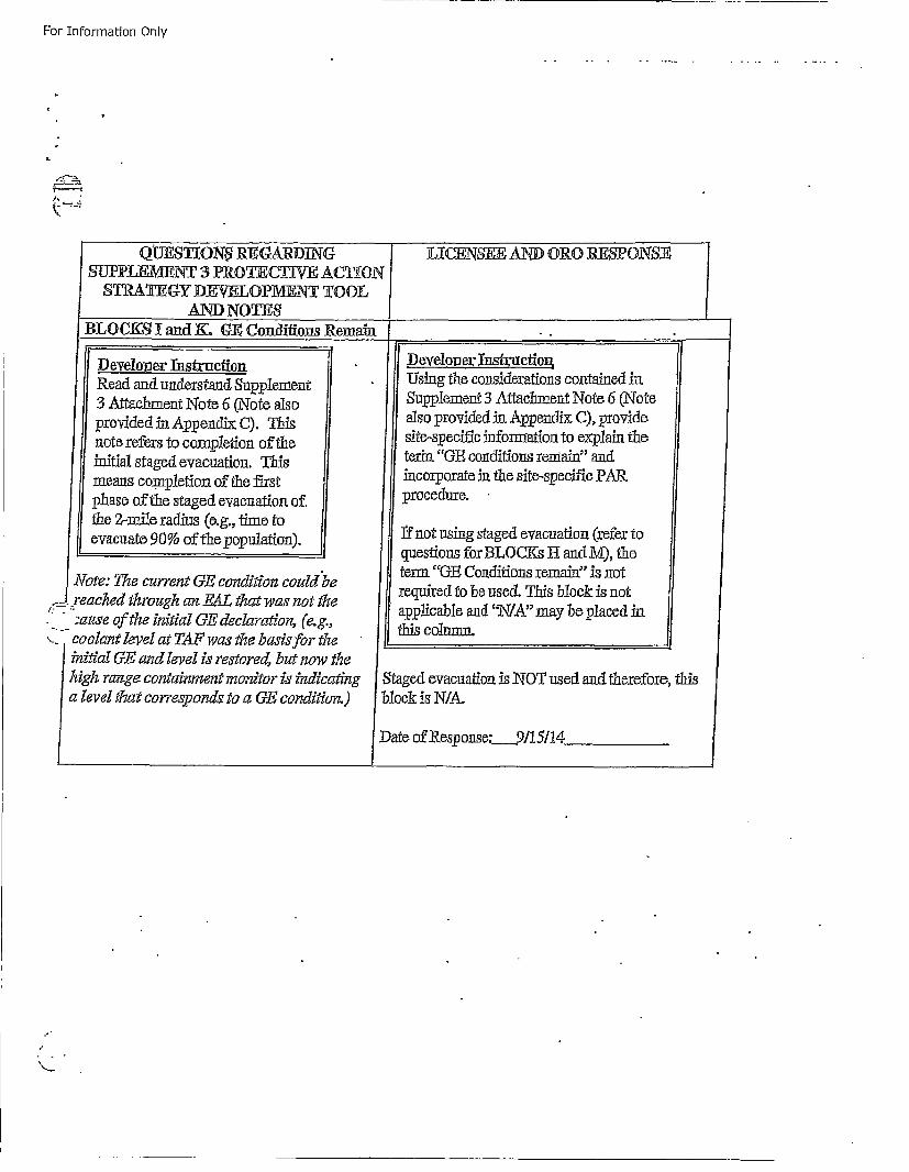
For- Information Only
QUESTION$ REGARD]iNGSUIL]WT3 POEfVEACTI0N
AND NOTESBLOCKS Z and K. GE Conditions Remain
LICENSEE AND ORO PRESPONSE
/Develouer InstructionRead and. understand, Supplement3 Attachment Note 6 (Note alsoprovided in Appendix C). Thisnote refers to completion of the
Sinitial staged evacuation. Thismeans completion of the firstphase of the staged evacuation of.the 2-mile radius (e.g., time toevacuate 90% of the population).
SNote: The current GE condition could be
x eached through an EAL that was not the/ ".- :auoe of the initial GE declaration, (e.g.,
c. oolant level at TAft was the basislfr the-initial GE and, level is restored, but now theI igh ran~ge containment monitor is indicatinga level that corresponds to a GE condition.)
IDeveloper !nstiuction.Using the considerations contained inSupplement 3 Attachmoent Note 6 (Notealso provided in Appendix: C), providesite-specifi infoimaiaon to explain theteria "GE conditions remain" andincorporate in the site-specific PARprocedure.
ffnot using staged evacuation (refer toquestions for BLOCKs II and M), theterm "GE Conditions remain" is notrequired to be used. This bl~ock is notapplicable and "N•/A" may be placed inthis cohumn.
Staged evacuation is NOT used and therefore, this
block is N/A.
SDate of Response: 9115114
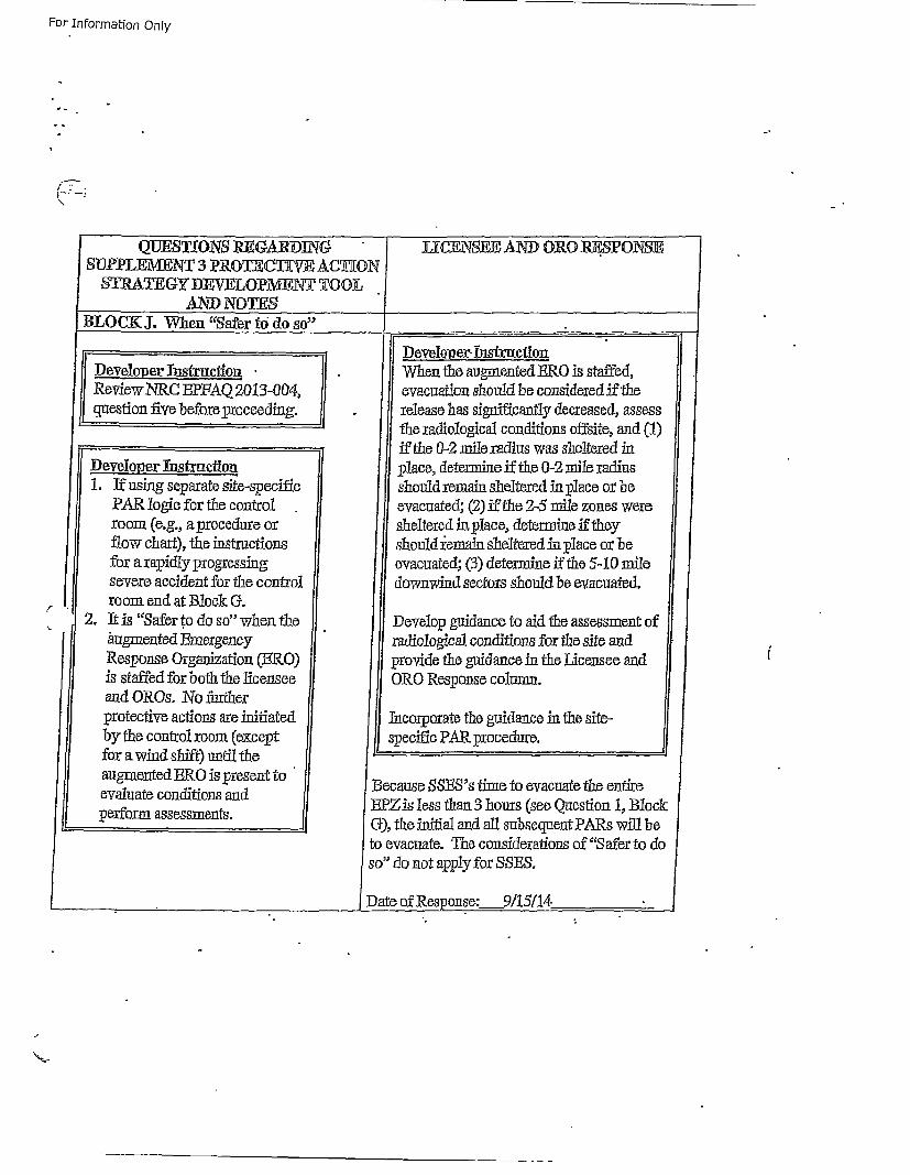
For Information Only
\:
QUJESJIONS R~EcGARDING [
SUPPLEMENTI 3 PR.OTECT][VE AC'UONSTRATEGY DRWVLOPl1¶ENT TOOL.
AND) NOTE9BLOCK Jt. When "safer 16 do so"
L'ICENSEE AND ORG RESPONSE
I
' IDevelo~ier ThsfrlctionR eview NRC EPFAQ 20113-004,
question five before proceeding.
D eveloper Thstruction
1. If using separate site-specificPAR logic for thle controlroom (e.g., a procedure orflow chart), the intructions
for a rapidly progressingsevere accident for the control
.• room end at Block G.2. It is "cSafer t~o do so" when the
a i ugmented EmergencyResponse Organization (BF.O)is staffed for: both the licenseeand eros. :No furtherprotective actions are initiatedby the control zoom (except
for a wind shift) unti the iaugmaented ERG is present toevaluate conditions andper_•€form assessments.
t-
[D evelop0 er-!nstructionWhen the augmented B•RO is staffed,evacuation should be considered if therelease has significantly decreased, assessthe radiological conditions offsite, and (1)if the 0-2 mile radius was sheltered inplace, determine if the 0-2 mile radiusshould remain sheltered in pflace or beevacuated; (2) if the 2-5 mile zones weresheltered in place, determine if theyshould jeznmin sheltered :in •place or beevacuated; (3) determine if the 5-10 miledownwind sectors should be evacuated.
Develop guidance to aid the assessment ofradiological conditions for the site andprovide the guidance in1 the Licensee andORO Response column.
Tncorporate the guidance in the site-specific PAR procedure.
Because SSES's time to evacuate the entireEPZis less than 3 hours (see Question 1, BlockQ), the initial and all subsequent PARs will beto evacuate. The considerations of "Safer to doso" do not apply for SSES,
,Date of Response:__9/15f!4
r
(
1 *t --
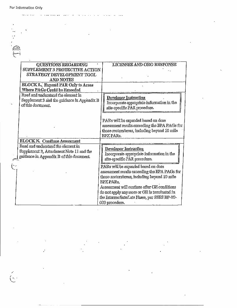
For Information Only
A ".
SUp:p:emVerNT 3 aid hegudaCei Appendix B..eoerTsrcfoi
LOf K This dc-ment d AROyore s iepefiPA.rodu.
PA~s will be expanded based on dose
assessment results exceeding the EPA PAGs forl
those sectors/areas, including beoyond 10 ruile,EPZ PARs.
...BLO(K iN. Continue Assessment _____________
IRead and understand the element inSuppllement 3, Attachment Note 1.1 and theguidance in Appendix B of tbis document.
D evelopoer Thstraetion.Incorporate approipriate information in thesite-specific PAR procedure.
PARs will be expanded based on doseassessment results exceeding the EPA PAGs forthose sectors/areas, including beyond 10 mileEPZ PARs.Assessment will continue after GB conditionsdo not ap~ply anymore or GB is terminated inthe I, ternedateiLate Phas, per sE EP-0O-003 poeue
f~2
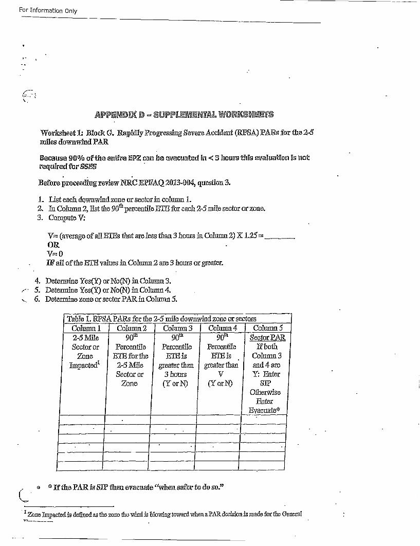
For Information Only
Worksheet 1: Block G. Rapidly P•rogressing Severe Acckient (RFSA) PARS for the 2•5miles downwind PAR
Because 90% of the entire EPZ can be evacuated in < 3 hours t:his evaluation is 1•o•
required for SSES
Before proceeding review" N-RC EF.2AQ 20•3-134D4, question 3.
1. List each downwind zone or sector in column it.2. Ia Column 2, list the 90'• percentile ET, T for eaech 2-5 mile sector or zone.3. Compnte V:
V=: (average of all RETEs that are less than 3 hours in Columna 2) X 1.25 =___OR.V= 0Ball of the BElE values in Column 2 are 3 hours or greater.
4. Determine Yes(Y) or No(N) in Columnn3.r- 5. Determine Yes(Yi) or No(N) in Column 4.,, 6. Determine zone or sector PAR. in Colutmn 5.
Table i. RIPSA PARs for the 2-5 mile downwind zone or sectorsColumn 1 Coltumn 2 Column 3 Column 4 Column 52-5 Mile 90m 90t 90t .Sector PAR,Sector or Percentile Percentile Percentile Yf both
Zone ETE forthe ETE is RI is Column 3Imp9acted1 2-5 Mi~le greater than greater than antd 4 are
Sector or 3 hours V Y: EnterZone (Y or N) (Y or N) SI
OtherwiseEnter
Evacuate*
o * If the PAR is SW[ then evacuate "when safer to do so."
' Zone Im~pactedis defined as the zone the 'wind is Tjlowing toward when a PAR decision is made for the General
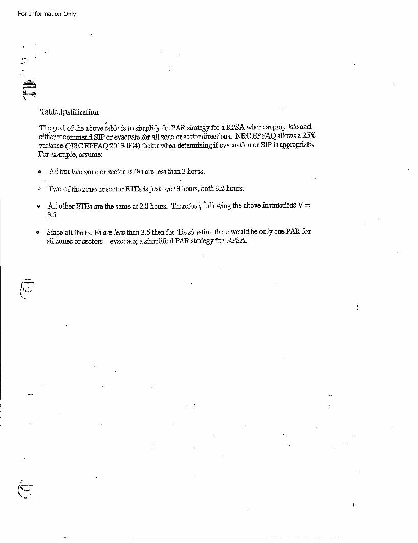
For Information Only
Table jutstiffcationThe goal of the above table is to si~mplify• the PAR. strategy for a iRPSA where apipropriate andeithler recommend SIP or evacuate for all, zone or sector directions. NRC BPFAQ allows a 25%'variance (NRC EPFAQ 2013-004) factor whech deter~mining if evacuation or SIP is appropriate.For examplIe, assume:
o All but two zone or sector BTEs are le~ss than 3 hours.
o Two of thle zone ox: sectorET~s is jus over 3 horeas, both 3.2 hours.
o All other EThs are the same at 2.8 htours. Therefore, following the above instructions V=3.5
aSince all the ETEs are less thman 3.5 then for this situation there would be only one PAR forall zones or sectors - evacuate; a simplified PAR strategy for RPSA.
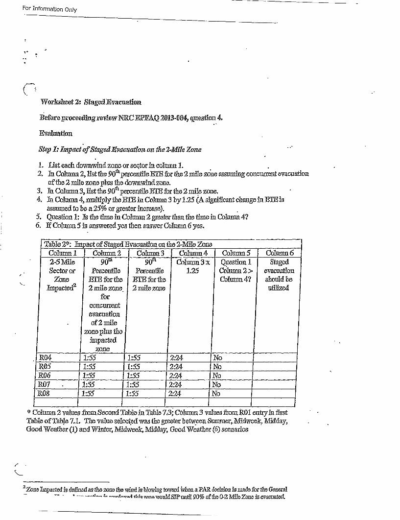
For- Information Only
Workshaeet 2: Staged Evacuation,
B•efor'e proceeding reviw NRC E]PP•AQ 2013-004, question 4.
Evaluation
Step 1; Impact "of Staged Evadllattolz on the 2.~Mile Zone
1. List each downwind zone or se&.tor in column 1.2. Ia1 Column 2, list the 90a* percentlile ETh for the 2 mile zone assumling concurr:ent evacuation
of the 2 mile zone plus the downwind zone.3. In Column 3, list the 90O• percentile B•Th for the 2 mile zone.4. In Column 4, multiplIy the £ETB in Column 3 by 1.25 (A significant change in BT~is
assumed to be a 25% or greater increase).5. Question 1: Is the time in Column 2 greater than the time in Colum~n 4?6. If Column 5 is answered yes then answer Column 6 yes.
[Table 2*: Ia 9act of Staged Evacuation on the 2-MVile ZoneColumn 1 Column 2 [.Column 3 Column 4 Column 5 Column 62.-51WMile 90t 90t Column 3 x Question 1 StagedSector or" Percentile Percentile 1.25 Column 2 > evacuation
,- Zone ETh for the ETR for the Cohumn 4? should be" hmpactedt2 2 mile zone 2 mile zone uttilized
forconcurrentevacuationof 2mile
zone plus theimpacted
zoneoR04 1:55 1:55 2:24 NoR05 1:55 1:55 2:2.4 No
SR06 1:55 1:55 2:24 No.P.07 - 1:55 1 :55 2:24 NoP.08 1:l55 1:551 2:24 No
* Column 2 values fr~om Second Table in Table 7,3;i Column 3 values from P.01 entry in firstTable of Tab.le 7.1. Thle value selected was thle greeter between Summer, Midweek7, Midday,Oood Weather (1) and Winter, 1M!idweek, Midday, Good Weather (6) scenarios
2 Zone Impacted is defined as the zone the wind in blowing toward 4vbeon a PAR decision is made for the General.......... "•- -'--- ...- ,4w ,A t7icnnP.won~d¶ until u190% of the 0-2 M~ile Zone is evacuated.
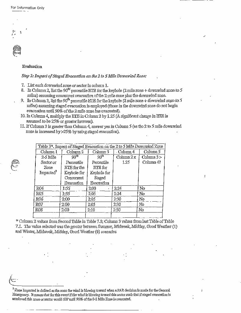
For Information Only
Evyaluation
Stepf 2: Xn~pctc of Staged Evacziadiozz on• the 2 to 5 Mile Downwind Zone:
7. List each dow-nwindzone or sector in column 1.8. In Column 2, list the 90m'percenfile ETE for the keyhole (2 mile zone + downwind zone to 5
miles) assuming concurrent evacuation of the 2 mile zone plus the downwind zone.9. In Column 3, list the 90m percentile ETE for the keyhole (2 mil e zone + dbwnwind zoiae to 5
miles) assuming staged evacuation is employed (those in the downwind zone do not beginevacuation until 90% of the2 -mile zone has evacuated).
10. In Colutmn 4, multipl1y the EgTE- i Column 2 by 1.25 (A significant change in BIB isassutmed to be 25% or greater increase).
i1. If Column 3 is giearer thant Colunm~t4, answer yes in Column 5 (as the 2 to 5Smile downwindzone is increased by >25% by using staged evacuation).
Table 3*. Impact of Staged Evacuation on the 2 to 5 Mile Downwind ZoneColumnl 1 Column 2 Column. 3 .Column 4 Column 52-5 Mile 90t 90t Column 2x ColumnS3>
_•Sector or P:ercentile Percentile 1.25 Column 4?_.Zone ETh for the ETB for
Tmpacted 3 Keyhole for Keyhole forConcur'rent StagedEvacuation 2Evacuation
R04 1:55 2:00 2:24 NoR05 1:55 2:05 2:24 ]NoR06 12:00 2:05 2:30 NoR07 2:00 2:05 I2:30 NoR08 2:00 [2:10 2:30 N-o
*- Column 2 values from Secon~d Table in Table 7.1; Column 3 ralues from last Table of Table7.1. The value selected was the greeter between. Summer, Midweek, Midd~ay, Good Weather (1)and Winter, Midweek, Midday, Good Weather (6) scenarios
3Zone Impoacted is defined as the zone the vvind is blowing to ward whsen a PAR. decision is made for the GeneralThnergency. It means that for this event if the wind is blowing toward this sector such that if staged evacuation isemtployed this zone or sector would STP nj~tij 90% of the 0-21Mile Zone is evacuated.
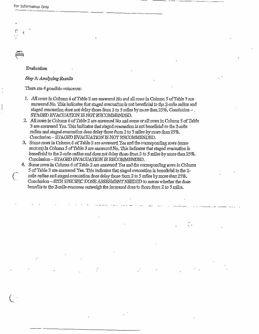
For Information Only
Evaluation
Step 3: Ancdyzing Resutif
There are 4 possible outcome~s:
1. Allrows in Couirm 6 of Table 2 are antswered No and all rows in Columnn 5 of Table 3 areanswered No. This indicates, that staged evacuation is not beneficial to the 2-mile radius andstaged evacuation does not delay those from 2 to 5.miles by more than 25%•. ConclusiontSTAGED BVACUAT[ON IS NOT RECO1\M2VTNDF.
2. All rows in Column 6 of Table 2 are answered No and some or all rows in Colum 5 of Table3 are answered Yes. This indicates that staged evacuation is not beneficial to the 2-milteradius and staged evacuation does delay those from 2 to 5miles by more than 25%.Conclusion -STAGED EVAUUAITION ES NOT RECOMMEINDED.
3. Some rows in Column 6 ofTable 2 are answered Yes and the corresponding rows (samesectors) in Column 5 of Table 3 are answered No. This indicates that staged evacuation isbeneficial to the 2-mile radius and does not delay those from 2 to rilies by more than 25%.Conclusion -STAGED EVACUATJON IS REceMvB'dED.
4. Some rows in Column 6 of Table 2 are answered Yes and the cotiiesp~onding rows in Column5 of Table 3 are answered Yes. This indicates that staged .evacutmion is beneficial to the 2-
S mileo radius and staged evacuation does delay those from 2 to 5 miles by more than 25%.Conclusion,- SlITE SPECWv.C DOSE ASSESMPIBNT NRDD to assess whtether the dosebenefits to the 2-mile evacuees outweigh the increased dose to those fr~om 2 to Srilies.
k. °
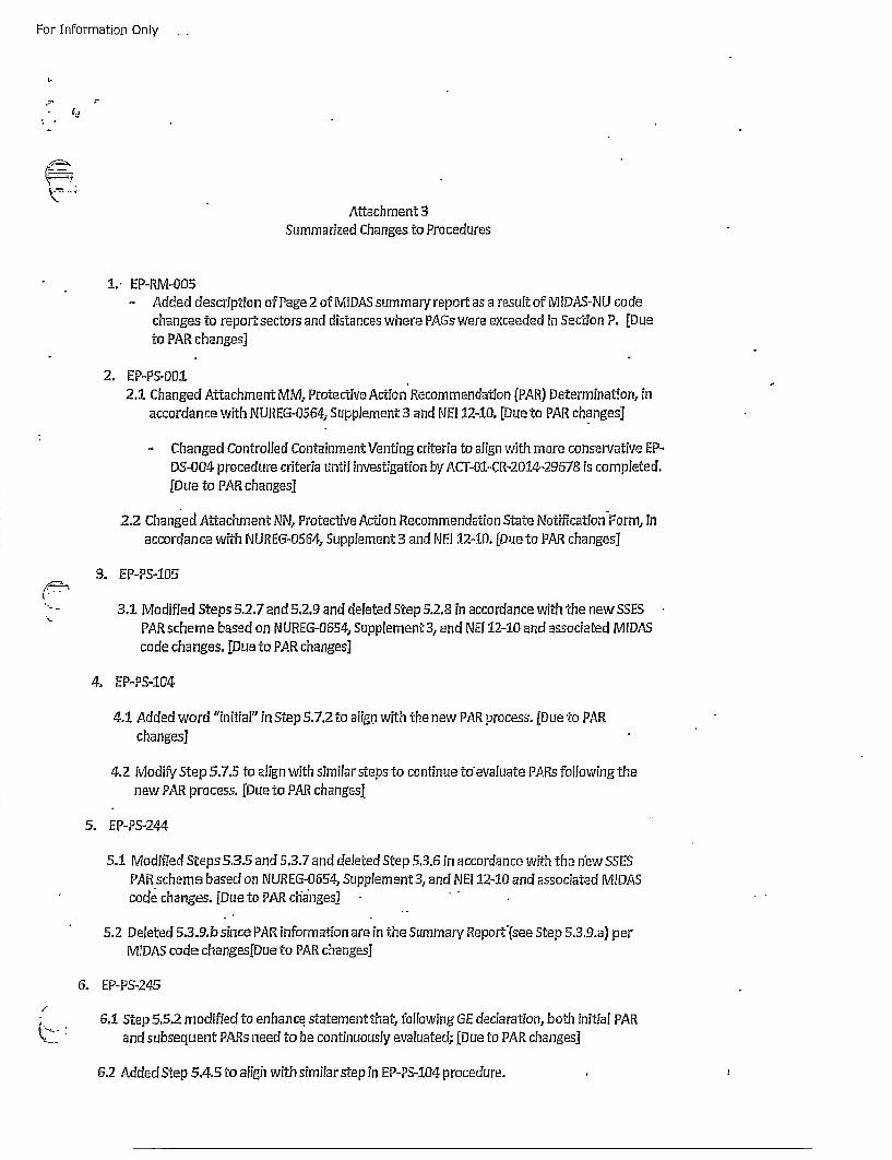
For Information Only
Attachment 3Summarized Changes to Procedures
1.- EP-RM-005
- Added descriptio n of Page 2 of MIDAS summary report as a result of MIDAS-NU codechanges to reportsectors and distances where PAGs were exceeded in Section P. [Dueto PAR changes]
2. EP-PS-JO1I2.1 Changed Attachment MM, Protective Action' Recommendation (PAR) Determination, in
accordance with NUREG-O564, Supplement 3 and NE! 12-10. [Due to PAR changes]
-Changed Controlled Containment Venting criteria to alrgn with more conservative EP-DS-004 procedure criteria until investigation by AGT-O1-CR-2014-29678 is completed.[Due to PAR changes]
2.2 Changed Attachment NN, Protective Action Recommendation State Notification Form, in
accordance with [NUREG-0564, Supplement 3 and NEJ 12-ID0. [Due to PAR changes]
3. EP-PS-!05
.... 3.1 Modified Steps 5.2.7 and 5.2.9 and deleted Step 5.2.8 in accordance with the new SSES
%. PAR scheme based on N UREc3-OSS4, Supplement 3, and NEI 12-10 and associated MIDAScode changes. [Due to PAR changes]
4. EP-PS-104
4.1 Added word "initial" in Step 5.7.2 to aligij with the new PAR process. [Due to PARchanges]
4.2 Modify Step 5.7.5 to align with similar steps to continue to'evaluate PARs following thenew PAR process. [Due to PAR changesj
5. EP-PS-244
5.1 Modified Steps 5.3.5 and 5.3.7 and deleted Step 5.3.6 in accordance with the niew SSESPAR scheme based on NUREG-0654, Supplement 3, and NEi 12-10 and associated MIDAS
* codte changes. [Due to PAR chianges]
5.2 Deleted 5.3.9.b since PAR information are in the Summary Reporf'(see Step 5.3.9.a) perMIDAS code changes[Due to PAR changes]
6. EP-PS-.245
"\-". 6.1 Step 5.5.2 modified to enhance, statement that, following GE declaration, both initial PARand subsequent PARs need to be continuously evaluated; [Due to P•AR changes]
6.2 Added Step 5.4.5 to aligh with similar step in EP-PS-104 procedure.
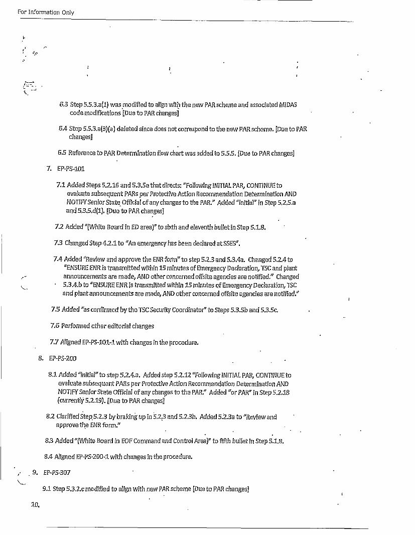
For Information Only
6. tp553a1 a oiidt lg it h e A ceeadascae IA
6.4 Step 5.5,3.a(3)(wa) deetdsine dtoe agno coreson t the new PAR schemeadaso iaued to PAR
changes]
6.5 Reference to PAR Determination flow chart was added to 5.5.5. [uue to PAR changes]
7. EP-PS-2.01
7.1 Added Steps 5.2.16 and 5.3.Se that directs: "Following INITIAL PAR, CONTINUE toevaluate subsequent PAA~s per Protective Action Recommendation Determination ANDNOTIFYSenior State Offcial of any changes to the PAR." Added "initia]" in Step 5.2.5.aand 5,3.5.d(1). [Due to PAR changes]
7.2 Added "(White Board in ED area)'7 to sixth and eleventh bullet in Step 5.1.8.
7.3 Changed Step 4.2.1 to "An emergency has been declared at SSES".
7.4 Added "Review and approve the ENR form" to step 5.2.3 and 5.3.4a. Changed 5.2.4 to"ENSURE ENR is transmitted within 15 minutes of Emergency Decdaration, TSC and plant
.,-- announcements are made, AND other concerned offsite agencies are notified." Changed
•,. 5.3.4.b to "ENSURE ENR is transmitted within 1/5 minutes of Emergency Declaration, TSCand plant announcements are made, AND other concerned offsite agencies are notified."
7.5 Added "as confirmed by the TSC Security Coordinator" to Steps 5.3.Sb and 5.3.5c.
7.6 Performed other editorial changes
7.7 Aligned EP-PS-101-1 with changes in the procedure.
8. EP-PS-2eOO
8.1 Added "initial" to step 5.2.4.a. Added step 5.2.:12 "Following INITIAL PAR, CONTINUE toevaluate subsequent PARs per Protective Action Recommendation Determination ANDNOTIF-Y Senior State Official of any changes to the PAR." Added "or PAR" in Step 5.2.18(currently 5.2.19). [Due to PAR changes]
8.2 Clarified Step.5.2.3 by braking up in 5.2.3 and 5.2.3b. Added 5.2.3a to "Review and
approve the ENR form."
8.3 Added "(White Board in EOF Command and Control Area)" to fifth bullet in Step 5.1.8.
8.4 Aligned EP-PS-2fJ0-4 with changes in the procedure.
,- 9. EP-PS-307
9,:1 Step 5.3.2.c modified to align with new PAR scheme [Due to PAR changes]
10.
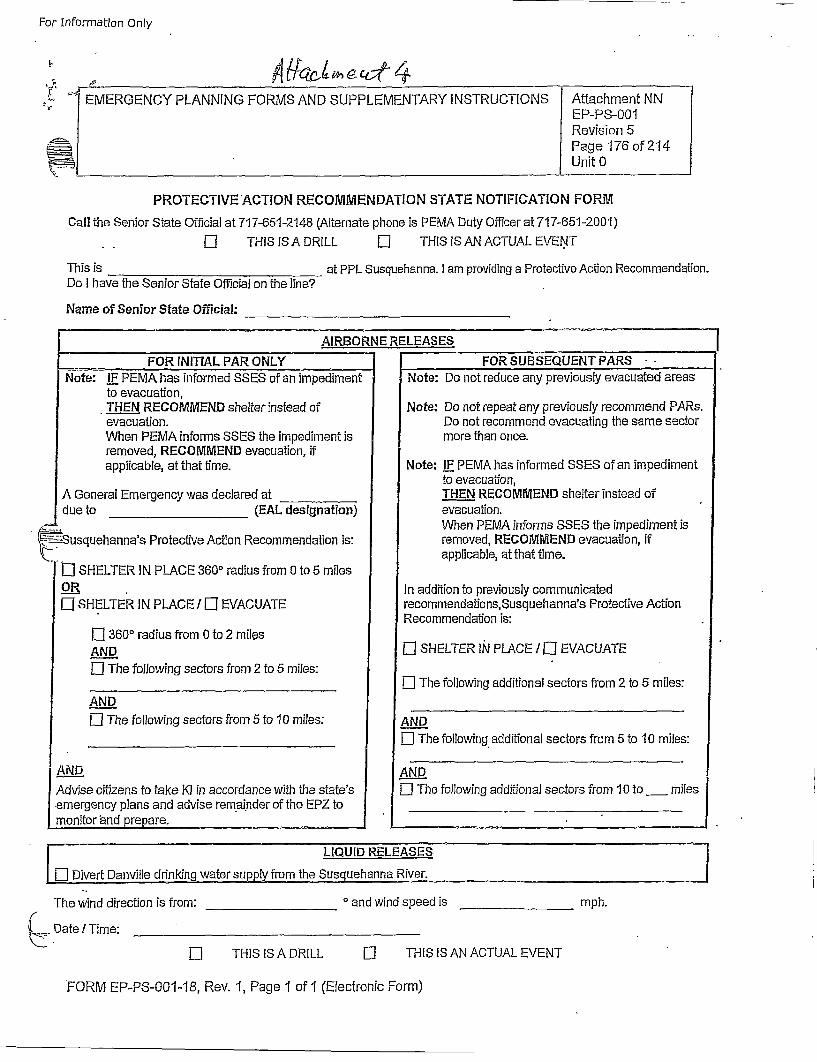
For Informat~ion Only
'0"I.
iIEMERGENCY PLANNING FORMS AND SUPPLEMENTARY INSTRUCTIONS Attachment NN
EP-PS-001Revision 5Page 176 of 214Unit 0
PROTECTIVE ACTION RECOMMENDATION STATE NOTIFICATION FORMCall the Senior State Official at 71 7-651-2148 (Alternate phone is PEMA Duty Officer at 717-651-2001)
.Li[ THIS IS A DRILL Li THIS IS AN ACTUAL EVENT
This is _________________at PPL Susquehanna. I am providing a Protective Action Recommendation.
Do I have the Senior State Official on the line?
Name of Senior State Official: ____________________
AIRBORNE RELEASES
FOR iNlTIAL PAR ONLY FOR SUBSEQUENT PARSNote: IFE PEMA has informed SSES of an impediment Note: Do not reduce any previously evacuated areas
to evacuation,.THE__..N RECOMMEND shelter instead of Note: Do not repeat any previously recommend PARs.evacuation. Do not recommend evacuating the same sectorWhen PEMA informs SSES the impediment is more than once.removed, RECOMMEND evacuation, ifapplicable, at that time. Note: IF PEMA has informed SSES of an impediment
to evacuation,A General Emergency was declared at T______._NTHN RECOMMEND shelter instead ofdue to ___________(EAL designation) evacuation.
~When PEMA informs SSES the impediment is~Susquehanna's Protective Action Recommendation is: removed, RECOMMEND evacuation, if
L•[i • SHELTER IN PLACE 3600 radius from 0 to 5 milesaplcbeathtti .
OR In addition to previously communicatedLi-SHELTER IN PLACE I Li EVACUATE recommendations, Susquehanna's Protective Action
Recommendation is:Li 3600 radius from 0 to 2 milesAN_..D Li SHELTER lN PLACE / Li EVACUATE
Li The following sectors from 2 to 5 miles:_______________________________ L The following additional sectors from 2 to 5 miles:
AN_.DD________________Li The following sectors from 5 to 10 miles: AND
_______________________________-L The following, additional sectors from 5 to 10 miles:
AND AN__D.Advise citizens to take 1(1 in accordance with the state's Li The following additional sectors from 10 to ___ milesemergency plans and advise rem~ainder of the EPZ to______________________monitor 'and prepare. _______________________
ii LIQUID RELEASES.
[]Divert Danville drinking water supply from the Susquehanna River.
The wind direction is from: ° and wind speed is __________mph.( .. ate I Time:_____________________
El THIS IS A DRILL Li THiS IS AN ACTUAL EVENT
FORM EP-PS-001-18, Rev. 1, Page 1 of 1 (Electronic Form)


![Der Gebirgsbote 1891 [Jg.59]](https://img.pdfslide.net/doc/110x75/63142887aca2b42b580d6f4e/der-gebirgsbote-1891-jg59.jpg)