Embed Size (px)
Citation preview

etters 252 (2006) 15–29www.elsevier.com/locate/epsl
Earth and Planetary Science L
Target delamination by spallation and ejecta dragging:An example from the Ries crater's periphery
Thomas Kenkmann a,⁎, Boris A. Ivanov b
a Museum of Natural History–Mineralogy, Humboldt-University Berlin, Invalidenstrasse 43, D-10115 Berlin, Germanyb Institute for Geodynamics and Geospheres, Russian Academy of Science, Leninsky Prospect, 38, 119334 Moscow, Russia
Received 20 March 2006; received in revised form 25 August 2006; accepted 25 August 2006Available online 27 October 2006
Editor: S. King
Abstract
Subhorizontal shear planes (detachments) are observed in bedded limestones in the periphery of the Ries impact crater,Germany. These detachments occur at 0.8–1.8 crater radii distance from the crater center beneath deposits of the continuous ejectablanket. Striations on detachment planes and offsets of markers indicate top-outward shearing with radial slip vectors. Detachmentswere found at depths between a few meters and more than 50 m beneath the target surface. The displacements along these faultsrange from meters to decameters and decrease with increasing depth and distance from the crater center. With increasing craterdistance, detachment horizons tend to climb to shallower levels. Cross-cutting relationships to faults associated with the cratercollapse indicate that detachment faulting started prior to the collapse but continued during crater modification. Numericalmodeling of the cratering process shows that near-surface deformation outside the transient crater is induced by two separatemechanisms: (i) weak spallation by interference of shock and release waves near the target surface and (ii) subsequent dragging bythe deposition of the ejecta curtain. Spallation causes an upward and outward directed motion of target material that increases inmagnitude toward the target surface. It leads to decoupling of the uppermost target layers in the early cratering stage without totallydisintegrating the rock. The subsequent arrival of the oblique impact shower of the ejecta curtain at the target surface delivers ahorizontal momentum to the uppermost target area and results in a second horizontal displacement increment by dragging. Withincreasing depth this effect vanishes rapidly. Spallation decoupling and subsequent ejecta dragging of near-surface rocks isprobably a general cratering mechanism around craters in layered targets with weak interbeds.© 2006 Elsevier B.V. All rights reserved.
Keywords: Ries crater; impact cratering; spallation; ejecta dragging; numerical modeling; detachment
1. Introduction
Impact craters are the most common features onplanetary surfaces and result from hypervelocity colli-
⁎ Corresponding author. Tel.: +49 30 20938878; fax: +49 30 20938565.
E-mail address: [email protected](T. Kenkmann).
0012-821X/$ - see front matter © 2006 Elsevier B.V. All rights reserved.doi:10.1016/j.epsl.2006.08.024
sions with asteroids and comets. The near-instantaneoustransfer of kinetic energy from projectile to targetcompresses rocks and causes the generation of a shockwave that expands roughly hemispherically into thetarget and back into the projectile. Rocks affected byshock are subjected to fracturing, brecciation, shockmetamorphism, melting, and vaporization depending onthe shock pressure, which in turn depends on the kineticenergy of the impactor and the distance to the point of

16 T. Kenkmann, B.A. Ivanov / Earth and Planetary Science Letters 252 (2006) 15–29
impact. Shock unloading of projectile and target beginswhen the shock wave is reflected at free surfaces like therear of the projectile or the target surface surroundingthe impact point. Shock and rarefaction waves set targetmaterial in motion and initiate an excavation flow thatopens the crater at a much lower velocity than the shockwave propagation velocity [1]. The kinematics of theexcavation flow are roughly described by the Z-model[2]; the end result is a parabolically shaped crater cavitymuch larger in size than the diameter of the projectile.The maximum extent of this cavity is known as thetransient crater. The end of excavation is reached at themoment when gravity forces stop the outward- andupward-directed motion of non-ejected material at therim of the crater and reverses its direction to begin thecollapse stage of crater formation.
The shockwave front passes through a given point at aspecific time, causing the onset of the target materialdisplacement. In the zone of the excavating flow, themain displacement occurs not during the passage of theshockwave, but at a later time during the excavationitself, when the shock wave has expanded far from theexcavation zone. However, near to the edge of theexcavation zone, outside the transient crater, the stressloading during the passage of the shock front may bemore intense than during the following stages ofcratering. In this zone displacement of near-surfacetarget, material may manifest itself as decoupling andjumping of coherent plates or blocks without total dis-integration of the entire rock. Generally, the target rocksaround the growing crater are damaged when appliedstresses exceed shear or tensile strength limits. At theperiphery of the fragmentation zone, the tensile strengthlimit is exceeded first, which results in the rock breakinginto Grady–Kipp fragments [3,4].
Along free surfaces (zero or ambient pressure planes)surrounding the point of impact, shock waves decayquickly because rarefaction waves rapidly reduce theshock pressure. The volume of material near the surfacein which the hemispherically expanding shock wavedoes not reach its full magnitude due to interference withrarefaction waves is called the interference zone [3]. Thethickness of this interference zone depends on the risetime in the shock wave front [1], which is controlled bythe target structure (layering, ground water table) androck properties (e.g., porosity). Target material in thisarea may be subjected to spallation: Steep pressuregradients accelerate weakly shocked spall plates to spe-cific ejection velocities that may reach a maximumcomparable with the impact velocity.
In addition, during the later stages of the craterformation, the uppermost target rocks just outside the
transient crater cavity are affected by the deposition ofejecta curtain material. The arrival of the ejecta curtain(end of the excavation phase) postdates spallation (earlyshock wave propagation) and, thus, encounters a pre-damaged and pre-decoupled target surface which isreadily prepared to be partially involved in the outward-directed ejecta-blanket flow. Both processes, near-sur-face spallation outside the excavated crater and defor-mation of target rocks during ejecta emplacement, arenot yet fully understood. Near the transient crater cavityrim both deformation increments may also be over-printed by the subsequent collapse of the transient cratercavity. The extent of crater collapse depends on impactenergy and gravity. The aim of this paper is to detect,analyze, and quantify the effects of weak spallation andejecta curtain dragging in near-surface target rockssurrounding transient crater cavities. For this purposewe used a combined approach of structural field analysisin the Ries crater and numerical simulations.
The Ries crater (Fig. 1) is the best suited large impactcrater on Earth to study processes of excavation andnear-surface deformation of target rocks as the amountof erosion is relatively small due to a long period ofshielding with post-crater marine sediments [5]. Thedeposits of the continuous ejecta blanket, the so-calledBunte Breccia, are widely preserved south and east ofthe crater but were eroded in the north and northwest.They extend up to three crater radii from the cratercenter. There are numerous sites where the underlyingtarget rocks can be studied at known levels beneath thecontact to the ejecta blanket. We have analysed thedeformation inventory of parautochthonous and autoch-thonous target rocks inside and outside the final(structural) crater rim and beneath the Bunte Brecciaat distances ranging from 10 to 22 km (0.8–1.8 craterradii) with respect to the crater center. A numericalmodel of the Ries impact event was used to derivedynamic physical parameters (displacement trajectories,pressure) for the region of interest and to compare thesemodel data with measurements in the field. The com-bined approach gives clues to the time sequence anddeformation processes that lead to the observed struc-tural features.
2. Geological outline of the Ries crater
After Shoemaker and Chao [6] had proven its impactorigin, the Ries crater, southern Germany (Fig. 1), becameone of the best studied craters on Earth. It is a pristinecomplex impact crater of ∼26 km diameter that formedduring the Miocene. New Ar–Ar laser probe datings oftektites yield an age of 14.34±0.08 Ma [7]. The Ries
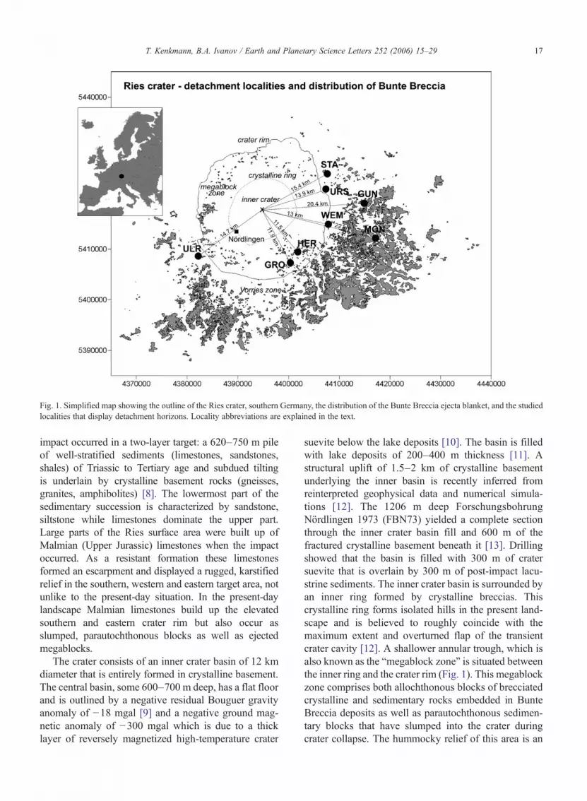
Fig. 1. Simplified map showing the outline of the Ries crater, southern Germany, the distribution of the Bunte Breccia ejecta blanket, and the studiedlocalities that display detachment horizons. Locality abbreviations are explained in the text.
17T. Kenkmann, B.A. Ivanov / Earth and Planetary Science Letters 252 (2006) 15–29
impact occurred in a two-layer target: a 620–750 m pileof well-stratified sediments (limestones, sandstones,shales) of Triassic to Tertiary age and subdued tiltingis underlain by crystalline basement rocks (gneisses,granites, amphibolites) [8]. The lowermost part of thesedimentary succession is characterized by sandstone,siltstone while limestones dominate the upper part.Large parts of the Ries surface area were built up ofMalmian (Upper Jurassic) limestones when the impactoccurred. As a resistant formation these limestonesformed an escarpment and displayed a rugged, karstifiedrelief in the southern, western and eastern target area, notunlike to the present-day situation. In the present-daylandscape Malmian limestones build up the elevatedsouthern and eastern crater rim but also occur asslumped, parautochthonous blocks as well as ejectedmegablocks.
The crater consists of an inner crater basin of 12 kmdiameter that is entirely formed in crystalline basement.The central basin, some 600–700 m deep, has a flat floorand is outlined by a negative residual Bouguer gravityanomaly of −18 mgal [9] and a negative ground mag-netic anomaly of −300 mgal which is due to a thicklayer of reversely magnetized high-temperature crater
suevite below the lake deposits [10]. The basin is filledwith lake deposits of 200–400 m thickness [11]. Astructural uplift of 1.5–2 km of crystalline basementunderlying the inner basin is recently inferred fromreinterpreted geophysical data and numerical simula-tions [12]. The 1206 m deep ForschungsbohrungNördlingen 1973 (FBN73) yielded a complete sectionthrough the inner crater basin fill and 600 m of thefractured crystalline basement beneath it [13]. Drillingshowed that the basin is filled with 300 m of cratersuevite that is overlain by 300 m of post-impact lacu-strine sediments. The inner crater basin is surrounded byan inner ring formed by crystalline breccias. Thiscrystalline ring forms isolated hills in the present land-scape and is believed to roughly coincide with themaximum extent and overturned flap of the transientcrater cavity [12]. A shallower annular trough, which isalso known as the “megablock zone” is situated betweenthe inner ring and the crater rim (Fig. 1). This megablockzone comprises both allochthonous blocks of brecciatedcrystalline and sedimentary rocks embedded in BunteBreccia deposits as well as parautochthonous sedimen-tary blocks that have slumped into the crater duringcrater collapse. The hummocky relief of this area is an

18 T. Kenkmann, B.A. Ivanov / Earth and Planetary Science Letters 252 (2006) 15–29
expression of its megablock nature. The tectonic craterrim could be defined in several geoelectric traverses[14,15] and a seismic section across the rim [10] by faultsthat separates autochthonous and downfaulted parau-tochthonous strata. The area outside the tectonic craterrim, the “Vorries zone”, is covered by the continuousejecta blanket (Bunte Breccia), allochthonous mega-blocks and patches of suevite. The ejecta of the Riescrater is composed of clastic polymict breccias (BunteBreccia) that extends up to three crater radii from theimpact center as a continuous ejecta blanket of decreasingthickness. Its constituents are mainly sedimentary rocks,with 5–10% of crystalline rocks. The ratio of primarycrater ejecta to local substrate components decreases withincreasing radial range [16]. Local and crater derivedmaterial are thoroughly mixed on all scales. It isinterpreted as a “cold”, non-cohesive impact formation[16–18]. In contrast, suevitic breccias predominantlyconsist of variously shocked and partly melted basementmaterial. Recent investigations showed that even thebreccia matrix contains high amounts of melted sedimen-tary and crystalline material [19]. Suevite achievesthicknesses of 300–400 m within the inner crater basin(crater suevite). Outside the crater, it occurs in 10–25-m-thick patches that extend up to two 22 km distance fromthe crater center (fallout suevite). The suevite-to-BunteBreccia contact is very sharp and indicates a hiatus anddifferent ejection mechanisms between the emplacementof the Bunte Breccia and the suevite. While the BunteBreccia deposits are regarded to be formed by ballisticejection and secondary mass transport [8,16], a processknown as ballistic sedimentation [20], the fallout sueviteis believed to be settled as a turbulent suspension of meltlumps and solid particles in amediumof hot gases from anexpanding vapor plume (e.g., [8,18]). Osinski [21]proposed that the fallout suevite was emplaced as groundhugging impact melt flows. However, an undisturbedsuevite-to-Bunte Breccia contact and delicate aerody-namical melt lump features within the suevite argueagainst this interpretation.
Sharp contacts of the Bunte Breccia ejecta blanketalso occur to the underlying rocks [16]. Striations oncontact surfaces revealed a radial flow [22,23]. However,obstacles of the pre-existing paleorelief caused deflec-tions by up to 30°. None of the contact planes of thelimestone target to the Bunte Breccia represents theancient pre-impact land surface, since weathering hori-zons are lacking. Soils and near-surface rocks wereincorporated in the ejecta flow. Seidl [24] and Wagner[22] were the first who observed subhorizontal displace-ments within Malmian target rocks beneath the ejectablanket-to-target contact and correctly interpreted there
kinematic history. Hüttner [25] and Chao [26] mis-interpreted these faults as striated target surfaces.
According to Stöffler et al. [27], the projectile mostlikely was a binary asteroid that near-simultaneouslyformed the much smaller Steinheim crater (3.8 kmdiameter) ∼40 km WSW of the Ries crater. Recentmodeling [27] suggests an oblique impact fromWSWthatalso accounts for the formation of the fan-like tektitestrewnfield (moldavites) in 250–400 km downrangedirection in the Czech Republic, East Germany andLowerAustria. The oblique impact scenario, however, didnot account for the occurrence of so-called Reuter'scheBlöcke south and southwest of the crater, which arebelieved to represent spallation products.
3. Methods
3.1. Structural analysis
Slip vectors on shear planes were determined bymeasuring the orientation of fault striae and grooves.Alternatively, striking of drag fold axes that are asso-ciated with the deformation increments of interest wereused for flow direction reconstructions. The hinge lineof such folds is oriented perpendicular to the slip vectorand the fold vergency indicates the sense of shear. Otheruseful shear sense criteria included the offsets of mar-kers and the ramp-and-flat geometry of detachmentplanes. The displacement magnitude along a detachmentwas most simply determined by measuring the offset ofa marker parallel to the shear direction. Very usefulmarkers were widened cleavage planes and, in partic-ular, vertically exposed karst pipes and caverns whichare frequent in thickly bedded limestones (Malmian δ).Other techniques use the displacement between twobenchmarks of the hanging wall and footwall of a faultthat initially belonged together. The length of a thrustramp yields minimum displacement magnitudes. If thehanging wall is folded the minimum displacement canbe estimated by calculating the difference between thelength of a bed in the fold and the shortest distance fromlimb to limb. Note that these latter techniques only yieldminimum displacement magnitudes. The “true” dis-placement is not specified and could be orders ofmagnitude higher.
3.2. Numerical modeling
A two-dimensional numerical model was designed tostudy the timing and extent of near-surface motion intarget rocks surrounding a transient crater cavity. Weused the SALEB hydrocode and ANEOS equation of

19T. Kenkmann, B.A. Ivanov / Earth and Planetary Science Letters 252 (2006) 15–29
state for limestone (the upper 800 m) and granite formodeling the Ries target. The computational cell sizewas mostly 50×50 m (early time control modeling uses25×25 m cells). We modeled an elliptical projectile equalin volume to a sphere with diameter D of 1.4 km anddensity 2600 kg/m3. The use of an elliptical projectile in atwo-dimensional model yields a shallower but broadercrater cavity than is the case for a spherical projectile, andthus provides a better approximation of the transient cratergeometry observed in oblique impact simulations. Thechosen impact velocity of 10 km/s corresponds to thevertical component of a 45° oblique impact at 14.1 km/s.The model is computed as an Eulerian grid. To revealLagrangian particlemotion and display displacements anddeformation, tracer mass-less particles (simply namedtracers), are emplaced in the center of each cell, recordingposition, pressure and inelastic strain in the target. The cellcentered parameters are recalculated for the current tracerposition with a bilinear interpolation method. A detailedstress–strain history has been recorded for selected tracersoriginally placed at ∼13 km distance from the center atvarious depths. This distancewas chosen sincemost of thestructural data were gained from here. Additional tracerscover a radial range from10km to 20 kmat shallow depth.
A set of additionalmodel parameterswas varied to finda best fit to the Ries crater morphology. The parameterstudy includes a variation in the decay time of acousticfluidization (25, 20, 16 s), and a change of the frictioncoefficient in damaged target material (0.4, 0.5) (formodel details see, e.g., [28]). The resulting best fit craterhas a diameter of 20–22 km and an inner ring of upliftedgranite of 12 km diameter that matches the “innercrystalline ring” of the Ries. Note that final crater sizeand the megablock zone are not reproduced perfectly. Ourmodeling yields similar results to that of [12].
Due to its two-dimensional axial symmetry themodel does not reproduce natural azimuthal variationsof target motions as observed in the field, particularlyfor oblique craters. Moreover, the model at the availableresolution describes deformed rocks as a continuummedia with a smooth distribution of strain. In contrast,real rocks are predominantly deformed along faults andfractures, separating much less deformed blocks. It is thehighly localized strain that is measured in rocks withinand around the Ries crater. To correlate field and modeldata one can estimate the average shear strain, dividingthe displacement along a localized shear zone by thecharacteristic block size. In our case, the effective blocksize was estimated as a thickness of a detached anddisplaced upper rock layer. This value can be comparedwith average shear strain in the model material. Tooutline the differential motion at the cell size scale
(50 m) we calculated the effective shear strain which isdefined as: s=(x(i,j)−x(i,j−1))/Dy, where i and j are theindices of cell row and column, respectively, and Dy isthe initial cell size.
4. Results
4.1. Structural data
Detachments were exclusively observed in flat-lyinglimestones of Malmian age, which built up large parts ofthe Ries target surface at the time of impact. These rocksformed an escarpment and displayed a rugged, karstifiedrelief in the southern, western and eastern target area.Withthe exception of isolated buttes, these limestones wereeroded in the northern part prior to impact. The contact oftarget surface rocks to the overlying ejecta deposits (BunteBreccia) is exposed at several sites. Detachments areformed within those limestones that display a rheologicalstratification formed by interbedded strata of thicklimestone beds and thin marly interbeds. Shear zonesare always localized in the incompetent layers. Massivereef limestones that occur at the southern rim of the Riesdo not show indications of surface-parallel detachmentfaulting. Figs. 2–4 and the following section describe theindividual detachments and the associated deformationinventory of the studied localities. Fig. 5 gives an over-view of the structural data and correlates magnitude ofdisplacement, depth of detachment, and distance to thecrater center. The following brief description of the out-crops is ordered clockwise with respect to theirgeographic positions (Figs. 1–4).
4.2. Description of studied localities
Stahlmühle (STA, 15.4 km NE of crater center (cc);1.23 crater radii): A major detachment plane is exposedin the NE edge of the limestone quarry (out of ope-ration). The length of detachment exposure is ∼40 m inthin-bedded limestones of Malmian β. The hanging-wall block shows strata undulations, low-angle stratacut-offs at the detachment, and remarkable folds(Fig. 2c). NW-striking folds display fold planes withNE vergency indicating top-NE motion. One major foldis disharmonic and shows sub-folds in its overturned NElimb (Fig. 2c). The major fold has an amplitude of∼7 mand is interpreted as a drag fold. A gradational succes-sion exists from detached and dragged blocks (para-utochthonous) to fully isolated megablocks outside thequarry being fully incorporated into the ejecta blanket.Previous outcrop analysis by [25], describing a differentoutcrop situation, also report thrust planes in Malmian δ

Fig. 2. (a) Grosssorheim (GRO): Line drawing of [22] shows a detachment horizon above unit C in Malmian β limestone. Unit D is locally overturnedby drag folding along the detachment. Comminuted and brecciated rock is injected between unit D and A, B. (b) Outcrop situation at Heroldingen(HER) displaying gentle small-scale folding in the hanging wall of a detachment formed in thin-bedded Malmian β limestones. Note that the quarrywall is in an obtuse angle to the tectonic transport direction. (c) Stahlmühle (STA): Asymmetric, disharmonic folding with local overturning occurs inthe hanging-wall strata of a Malmian β detachment. Bunte Breccia is situated above the quarry wall.
20 T. Kenkmann, B.A. Ivanov / Earth and Planetary Science Letters 252 (2006) 15–29
limestones, and striated contact surface (50–65° strike)to the Bunte Breccia.
Ursheim E (URS, 13.9 km NE of cc; 1.11 craterradii): The flat lying sequence of Malmian β2 and γ1limestones appears rather undeformed, but two bed-ding-parallel weathered horizons 12–15 m beneath thecontact to the Bunte Breccia still exist that show top-Eoffsets with 1.0–1.2 m displacement of major cleavageplanes. Shear planes coincide with interfaces of lime-stone beds. They were already described by [22](Fig. 3a) who reports EW striae on these surfaces(90–100° strike).
Wemding (WEM, 12.9–13.4 km E of cc; 1.03–1.07crater radii): This operating quarry is located at theeastern rim of the crater. The western part displaysweakly inclined (10–20° towards NW), thickly beddedlimestones of Malmian δ that are partly affected bykarstification and that are overlain by remnants of theejecta blanket. Karst caverns are filled with fluviatileconglomerates (Fig. 4c) of pre-Ries age. Beddingparallel detachment horizons can be observed at differ-ent levels between 15 and 30 m depth beneath thecontact to the Bunte Breccia (Fig. 4a, b, e) and were alsorecorded in previous mining stages [14,26]. Top-E
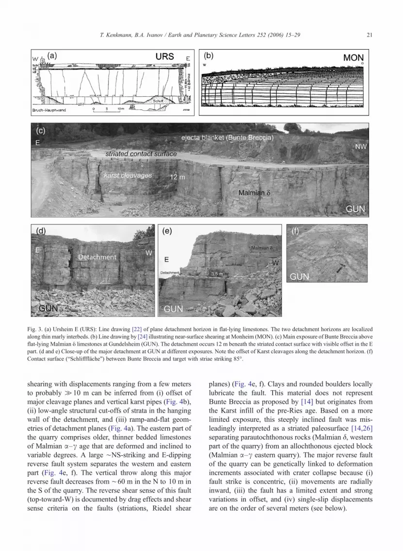
Fig. 3. (a) Ursheim E (URS): Line drawing [22] of plane detachment horizon in flat-lying limestones. The two detachment horizons are localizedalong thin marly interbeds. (b) Line drawing by [24] illustrating near-surface shearing at Monheim (MON). (c) Main exposure of Bunte Breccia aboveflat-lying Malmian δ limestones at Gundelsheim (GUN). The detachment occurs 12 m beneath the striated contact surface with visible offset in the Epart. (d and e) Close-up of the major detachment at GUN at different exposures. Note the offset of Karst cleavages along the detachment horizon. (f)Contact surface (“Schlifffläche”) between Bunte Breccia and target with striae striking 85°.
21T. Kenkmann, B.A. Ivanov / Earth and Planetary Science Letters 252 (2006) 15–29
shearing with displacements ranging from a few metersto probably ≫10 m can be inferred from (i) offset ofmajor cleavage planes and vertical karst pipes (Fig. 4b),(ii) low-angle structural cut-offs of strata in the hangingwall of the detachment, and (iii) ramp-and-flat geom-etries of detachment planes (Fig. 4a). The eastern part ofthe quarry comprises older, thinner bedded limestonesof Malmian α–γ age that are deformed and inclined tovariable degrees. A large ∼NS-striking and E-dippingreverse fault system separates the western and easternpart (Fig. 4e, f). The vertical throw along this majorreverse fault decreases from ∼60 m in the N to 10 m inthe S of the quarry. The reverse shear sense of this fault(top-toward-W) is documented by drag effects and shearsense criteria on the faults (striations, Riedel shear
planes) (Fig. 4e, f). Clays and rounded boulders locallylubricate the fault. This material does not representBunte Breccia as proposed by [14] but originates fromthe Karst infill of the pre-Ries age. Based on a morelimited exposure, this steeply inclined fault was mis-leadingly interpreted as a striated paleosurface [14,26]separating parautochthonous rocks (Malmian δ, westernpart of the quarry) from an allochthonous ejected block(Malmian α–γ eastern quarry). The major reverse faultof the quarry can be genetically linked to deformationincrements associated with crater collapse because (i)fault strike is concentric, (ii) movements are radiallyinward, (iii) the fault has a limited extent and strongvariations in offset, and (iv) single-slip displacementsare on the order of several meters (see below).

Fig. 4. Wemding (WEM): (a) Detachment and associated hanging-wall deformation in Malmian δ limestone. The detachment is truncated in the E bya reverse fault that was active during crater collapse. Motion on detachment plane is deflected to higher stratigraphic levels. (b) Two main detachmenthorizons with visible offsets, shown during earlier quarrying operation [23]. (c) Preimpact fluviatile infill of a vertical karst cavern in Malmian δlimestones. (d) Injection of preimpact fluviatile karst pipe infill along a detachment plane. (e and f) Reverve fault associated with crater modificationcuts the detachment plane and, therefore, postdates detachment faulting. However, interference of subsidiary faults suggests ongoing radial outwardmotion.
22 T. Kenkmann, B.A. Ivanov / Earth and Planetary Science Letters 252 (2006) 15–29
The detachments of the western unit (Malmian δ) aretruncated by the major NS trending reverse fault, andhence, these detachments were formed prior to the
reverse fault. Dragging along the main reverse faultcaused the opening of the detachment plane (Fig. 4a).This led to an injection of pre-Ries conglomerates and

Fig. 5. Summary of structural data of analyzed detachment planes.(a) Distance from crater center versus depth of detachment beneathcontact to the Bunte Breccia. (b) distance from crater center versusdisplacement. (c) depth of detachment versus displacement. Fordiscussion see text.
23T. Kenkmann, B.A. Ivanov / Earth and Planetary Science Letters 252 (2006) 15–29
clays of the Karst pipes (Fig. 4c) into the gaping plane(Fig. 4d). Near the reverse fault, the hanging wall of thedetachment shows frequent splays that propagate tohigher levels (Fig. 4a). The complex interplay of east-ward motion along the detachments and W-directedsteep reverse faulting (Fig. 4a, c) indicates that detach-ment faulting started prior to reverse faulting but was
still ongoing when main reverse faulting occurred.When crater outward motion along the detachmentstarted to be blocked by the onset of reverse faulting,shear planes were deflected to higher stratigraphiclevels.
Gundelsheim (GUN, 20.4 km E of cc; 1.63 craterradii): The operating quarry is situated 7.5 km outsidethe crater rim and displays flat-lying, thickly beddedMalmian δ limestones that are overlain by 8 m of BunteBreccia (Fig. 3c), composed of limestone and colouredshale blocks. The striated contact surface (“Schliff-fläche”) with parallel striae and grooves (85° strike)indicates the radial outward directed flow of the BunteBreccia (Fig. 3f). About 12 m beneath the contactsurface a major detachment plane is exposed (Fig. 3c–e)with displacements ranging from 1.2 to 3.5 m. Thedetachment is localized along a marly interbed and leadsto offsets of major cleavage planes and Karst pipes.
Monheim (MON, 22 km E of cc; 1.76 crater radii):An ancient, now non-existent outcrop is described by[24] that illustrates near-surface shearing (Fig. 3b) alongseveral shear planes with displacements in the order of1 m.
Heroldingen (HER, 11.5 km SE of cc; 0.92 craterradii): Interbedded strata of marls and limestones ofMalmian β display small-scaled open folds in thehanging wall of layer-parallel shear planes (Fig. 2b).Small-scale ramp-and-flat thrusts can also be observedand indicate relatively small displacements. The entiresequence was downfaulted during crater collapse. At thesouthern crater rimMalmian βwas overlain byMalmianγ and δ rocks. This must be considered when estimatingthe depth of detachment.
Grosssorheim E (11.9 km SE of cc; 0.95 crater radii):This old quarry of Malmian β limestones was analyzedin detail by [22]. It shows an upper unit that is decoupledfrom a basal unit along a flat lying shear plane that iscomminuted and striated (135° strike). The upper unit ispartly folded. Drag folding leads to local overturningnear the detachment (fold strike ∼100°) (Fig. 2a).
Ulrichsruhe (ULR, 14.7 km SW of cc; 1.18 craterradii): This quarry outside the crater rim operates inMalmian ζ limestone and dolostone that are overlain byBunte Breccia. Deformation near the contact to the BunteBreccia is indicated by thrust planes with ramp-and-flatgeometry and associated thrust propagation folds.
4.3. Summary of structural observations andmeasurements
Detachment faulting along the crater rim and in theperiphery of the crater (Vorries zone) always shows

24 T. Kenkmann, B.A. Ivanov / Earth and Planetary Science Letters 252 (2006) 15–29

25T. Kenkmann, B.A. Ivanov / Earth and Planetary Science Letters 252 (2006) 15–29
radial top-outward-displacement of the hanging wallblock. This is indicated by striations on shear planes,offsets of major cleavage planes and pre-impact karstcaverns, and by the vergency of drag folds of the hangingwall strata. Locally a switch in the detachment horizonwas observed in the form of ramp-and-flat geometriesleading to low-angle cut-offs of strata. Detachmentswere also recognized by the occurrence of brecciatedmaterial injected along the shear planes. Detachmentsare formed some 1–60 m below the contact of theMalmian to the overlying Bunte Breccia (Fig. 5). Thedepths of detachment beneath the ejecta blanketdecreases with increasing distance from the crater center[29] (Fig. 5a). The measured radial displacement is in therange of 1–15 m. Note that some techniques merelyprovide an estimate of minimum displacement andproduce large error bars in Fig. 5. The magnitude ofdisplacement seems to decrease with increasing distancefrom the crater center (Fig. 5b), although this trend is notclear. Moreover, the magnitude of displacement seems toincrease the shallower the detachment is situated. Thissuggests a genetic link between the emplacement of theejecta blanket and the occurrences of detachment planes.The interference of detachments with normal and reversefaults that are linked to the collapse stage of crateringsuggests that detachment formation started prior to thecrater collapse but had not come to rest when collapseinduced faulting started. The structural observations andtime relationships reveal that detachment faulting anddecoupling of upper target layers started very early andcould be caused by moderate to weak spallation outsidethe transient cavity. Ongoing outward shearing duringcrater collapse (see WEM) could be related to draggingeffects induced by the ejecta curtain [29].
4.4. Results of the numerical simulation
The numerical model derives a sequence of motionevents of near-surface target material for double-layertargets that scale to the Ries impact crater (Fig. 6). At the“real” Ries crater, however, the wave motion is expectedto be more complex due to multiple reflections and
Fig. 6. Results of the numerical modeling. The horizontal (a, d–f) and verticalof time. (a) and (b) focus on the early tracer motions, (c–f) display the complwith depth at 13 km distance from the crater center corresponds to the elasticbasement (steep dashed line). Dashed curves in each frame show Z-model pgrowth in an incompressible media. (b) Vertical velocity at various depth at rafree fall in the gravity field. Tracers at initial depth of 375 m and below demTracer at 825 m depth is located in the basement. (c, d) Complete history of th13 km radial distance. Tracers at depths of 75 m and 175 m demonstrate a h~51 s. (e, f) History of the horizontal velocity component (e) and finite horizofrom 10 to 18 km. The black lines delineate the arrival of the ejecta curtain.
refractions at strata boundaries within its sedimentarysuccession. Tracer particles recorded the absolute mo-tion of material in the periphery of the transient cratercavity at a depth ranging from 75 m down to 825 mbeneath the target surface for a period of 80 s after theimpact. The onset of near-surface particle motion(horizontal and vertical) with radial range and depth isdisplayed in Fig. 6a and b, respectively. The first motionoccurs about 2 s after the impact and corresponds to thearrival of stress waves propagating through the base-ment and refracted to the sedimentary layer (Fig. 6a, b).The rapid decay of this first velocity pulse is due totarget fracturing. Subsequent motions in the following20–30 s is explained with mass motions around thegrowing transient cavity. For comparison, we calculatedthe transient cavity growth using the Z-model [2] withZ=2.7 and computed the motion (dashed line) withradial distance. The growth of the cavity lasts about 30 s,followed by the transient cavity collapse. The velocitymagnitude for the Z-model and the numerical model issimilar, particularly at 12 km distance.
Fig. 6b shows the onset in vertical velocity as afunction of time and depth at 13 km radial distance. Theprofile is indicative to delineate the depth to whichspallation occurs. Spallation means the ballistic ejectionof decoupled, coherent target blocks. The dashed linescorrespond to the free fall in the gravity field. One cansee that tracers at initial depths of 75 and 175 m followthis line for 2 s and, thus, experience spallation, whereastracers at deeper levels (initial depth of 375m and below)demonstrate the absence of free fall and, hence, the ceaseof spallation. We introduce the term “weak spallation” toexpress the low speed and small amount of decoupling.
The entire vertical and horizontal velocity history forthe same tracer column is given in Fig. 6c and d. A secondhorizontal velocity excursion occurs ∼51 s after theimpact. This event has only a subdued vertical compo-nent. This part of the particle motion can be correlated tothe passage of the ejecta curtain (Fig. 7). The horizontalvelocity component of the obliquely impacting ejectareaches a magnitude of 240 m/s near the target surface at13 km distance from the crater center (Fig. 7). Due to
(b–c) velocity components of tracer particles are displayed as a functionete record for 80 s. (a) The shift in the onset of horizontal tracer motionlongitudinal sound velocity (cL=6.95 km/s) for the modeled graniticredictions for the near-surface ground motion due to transient cavitydial distance of 13 km from the center. Dashed lines correspond to theonstrate the absence of free fall and, therefore, the cease of spallation.e vertical (c) and horizontal (d) velocity component of tracers located atorizontal motion induced by the passage of the eject curtain drag afterntal displacement (f) of tracers at 75 m depth located at radial distances

Fig. 7. Horizontal velocity distribution of the ejecta curtain and ejecta blanket in two time steps (∼40 s and 51 s, respectively), visualized by colourcoding.
26 T. Kenkmann, B.A. Ivanov / Earth and Planetary Science Letters 252 (2006) 15–29
oblique trajectories of the ejecta curtain a horizontalmomentum is delivered to the uppermost target area andresults in a horizontal displacement increment by dragging.Ejecta dragging causes a distinct spike of 10–12 m/s thatlast for a few seconds. The dragging-induced horizontaldisplacement vanishes with depth and cannot be detectedat a depth of 375mandbelow (Fig. 6d). This trend inmind,it is straightforward to further focus on the uppermosttracers at 75 m depth for various crater distances: Fig. 6eillustrates the ejecta dragging effect for a radial distanceranging from 10 to 18 km. Amplitude and shape of theejecta-induced velocity spikes change remarkably with
distance and become narrower. The non-uniform changesreflect the circumstance that ejecta deposited at the surfaceas lumps of material. Azimuthal variations, as expected,e.g., for oblique impacts or rayed ejecta would furtherinfluence the pattern in 3D models. The total amount ofoutward shearing of near-surface material is the sum of(i) spallation, (ii) the distant effect of transient cavitygrowth, and (iii) ejecta-induced dragging (Fig. 6f). Itamounts to N1000 m at 10 km near the transient cavityrim and decays to ∼40 m at 18 km distance. Ejectadragging adds a few decameters to total displacementbudget (Fig. 6f).

Fig. 8. Effective shear strain, s, vs. radial distance at a depth of 50 m (black circles), 100 m (open circles), 150 m (triangles) and 200 m (squares). Asthe upper subsurface cell row is disturbed by mixing with ejecta, these data show the largest noise. Data for effective shear strain follow a power-lawdecay with radial range (solid lines). Black crosses are field data recalculated for effective shear strain.
27T. Kenkmann, B.A. Ivanov / Earth and Planetary Science Letters 252 (2006) 15–29
A comparison of shear strains recorded in the modeland obtained by field observation is very crude, as no bulkstrain could be measured directly in the field and wasinstead simply calculated by dividing the measured sheardisplacement by the depth of the shear plain. Fig. 8 showsthe effective shear strain, s, with increasing radial distanceas obtained from the model for various depths (50 m,100 m, 150 m, 200 m). The effective shear strain decaysbothwith depth and radial range from the center. The solidcurves show power law trends for s at each depth (theexponent for the radial decay is around −7 for 10–20 kmdistances). Black crosses in Fig. 8 display our field datarecalculated for effective shear strain. Note that field dataonly cover a range of 10–60 m depth and, thus, can onlybe compared with the model data for 50 m depth (blackcircles) (Fig. 8). According to the model, the shear de-formation should be presented in most of upper sedi-mentary layers to depths of a few hundred meters atleast. The model can, of course, not predict where andhow shear localization occurs. From most field dataeffective shear strains are obtained with magnitudes inthe range of s∼0.1–1. A reasonably good agreement ins between field and model data is achieved for distancesof 20–22 km from the crater center. The misfit increasesto smaller distances.
5. Discussion and conclusion
We have observed several subhorizontal shear planes(detachments) in stratified target rocks at the crater rimand in the periphery of the Ries crater in Germany, andmeasured their displacement vector and magnitude. Asystematic dependency seems to occur between the dis-placement and depth of these detachments and their dis-tance with respect to the impact center. In combination
with a numerical model we show that early spallation andsubsequent dragging of the ejecta curtain are most likelyresponsible for the formation of detachments in the sur-rounding of the transient crater cavity. Modeling hasshown that the effect of spallation followed by distanteffects of transient cavity growth may dominate the effectof later dragging. This may, however, also depend on thespall strength of the material involved. Grady [30] deter-mined a spall strength of 77 MPa for a Solnhofen lime-stone sample independent of impact amplitude,representing an upper strength level as rocks in naturalstate typically have a lot of fractures, decreasing the largescale strength. The effect of weak spallation in theperiphery of the transient crater cavity can be enhanced bythe layering of target material. Head and Melosh [31]demonstrated that a low-velocity layer of a thicknesscorresponding to the projectile radius can increase thespall velocity by steepening the near-surface pressuregradient. The rheological stratification of the Ries with a700–800 m thick pile of sediments resting on a crystallinebasement corresponds to the estimated projectile radius [8]and, thus, provides the prerequisite for effective spallation.
Modeling shows that spallation and ejecta draggingare two temporarily clearly distinct deformation incre-ments with a hiatus of more than 30 s at one crater radiusdistance (final crater size). Since deformation featuresanalyzed in the field always represent the sum of alldeformation increments it is not easy to distinguishbetween both phases. However, it was possible todemonstrate that detachment faulting is the first craterrelated deformation increment. At the quarry Wemding(WEM), it could be demonstrated that radially outwarddirected motion did not come to rest when the gravity-driven collapse started. This indicates that ejecta curtaindragging played an important role for the total

28 T. Kenkmann, B.A. Ivanov / Earth and Planetary Science Letters 252 (2006) 15–29
displacement budget. The numerical model probablyunderrates the importance of the Bunte Breccia flowbecause it cannot accurately simulate the dynamics of theturbulent ejecta emplacement and complex groundmotion that occur during ballistic sedimentation [20,16].As the ejecta curtain expands over the target surface itentrains more and more locally derived surface materialinto a forceful radial outward flow. Near-surface delam-ination, detachment faulting, and hanging-wall draggingare precursor stages of the full incorporation of targetmaterial into the ejecta blanket. Moreover, the role ofdragging of the ejecta could differ if atmospheric effectsand impact obliquity are taken into account. Barnouin-Jhaand Schultz [32] have shown that the geometry of theejecta curtain is strongly affected by self-generatedturbulent winds that can influence surface dragging.
The aim of the presented modeling was not to predictevery detail observed in the field, but rather to determinethe time sequence and extent of the major target motions(which are well modeled at the available resolution) andto provide boundary conditions for future, more detailedmodeling work utilizing 3D numerical hydrocodes. Themodeling is in some senses crude because of the lowresolution of the mesh, and because some importantphysics were not implemented into the model, mostsignificantly the effect of the fine-scale layering of thesedimentary target units, the effect of the atmospheredrag on ejecta emplacement, and an accurate descriptionof the turbulent interaction of the ejecta with the targeton which it lands. Note that in axial symmetrical 2Dmodeling each ejecta fragment represents a torus ofmaterial, while 3D ejecta may arrive as a stochasticcloud of ejected debris. A local 3D modeling is thus aprerequisite to refine theoretical predictions of a com-plex near-surface rock deformation.
We, therefore, emphasize that the model should not beover-interpreted. The modeling we used here to create aguideline for field data analysis is still very crude, as thecell-size is defined by a necessity to compute the entirecratering event to produce a proper loading pattern forstress waves and the depositing ejecta. The model isspecifically designed to analyze the gross picture and timesequence of near-surface target deformation of a Ries-scale impact event. The presented low-resolution modelmay be used to construct boundary conditions for higherresolution models that focus on smaller areas. However,with the model accuracy available to date we can clearlystate in accordance to field observations that for Ries-scale craters the upper ∼100 m of the target should beaffected by the deposition of the ejecta curtain. Draggingnear the target surface by the ejecta cause horizontalvelocites of 5–50 m/s and displacements of a few deca-
meters at distances from 10 to 20 km from the Ries cratercenter. The pulse duration decreases with distance.
Near-surface decoupling of target material in theperiphery of a crater may not occur uniquely at the Ries. Itprobably happened at the Lockne crater, Central Sweden[33] and is also recognized at Haughton Dome (Osinski,personal communication). The occurrence of subhori-zontal dike systems in Cretaceaous target rocks of theChicxulub crater (identified near the contact to sueviticejecta at the Yaxcopoil drill site, 60 km distance fromcrater center) was interpreted as evidence for spallationdecoupling [34]. Recently, lobe-parallel furrows andridges structuring the inner portions of fluidized ejectablankets of Martian impact craters, likewise require targetdetachments for their formation [5].
Acknowledgement
The paper has benefited from discussions with D.Stöffler, W. v. Engelhardt, J. Pohl and R. Hüttner overyears. B. Ivanov is grateful to the Alexander vonHumboldt Foundation for the Research Prize, whichmade it possible to collaborate with T. Kenkmann inGermany. We are grateful to an anonymous reviewerand, in particular, to G. Collins for his very thoroughcomments and review.
References
[1] H.J. Melosh, Impact cratering. A geologic process, Oxf. Monogr.Geol. Geophys. 11 (1989) (245 pp.).
[2] D.E. Maxwell, Simple Z model of cratering, ejection, and theoverturned flap, in: D.J. Roddy, R.O. Pepin, R.B. Merill (Eds.),Impact and Explosion Cratering, Pergamon Press, New York,1977, pp. 1003–1008.
[3] H.J. Melosh, Impact ejection, spallation, and the origin ofmeteorites, Icarus 59 (1984) 234–260.
[4] D.E. Grady, M.E. Kipp, The micromechanics of impact fractureof rock, Int. J. Rock Mech. Min. Sci. Geomech. Abstr. 16 (1979)293–302.
[5] T. Kenkmann, F. Schönian, Ries and Chicxulub: impact craterson Earth provide insights for Martian ejecta blankets, Meteorit.Planet. Sci. 41 (2006).
[6] E.M. Shoemaker, E.C.T. Chao, New evidence for the impactorigin of the Ries Basin, Bavaria, Germany, J. Geophys. Res. 66(1961) 3371–3378.
[7] M.A. Laurenzi, G. Bigazzi, M.L. Balestrieri, V. Bouska, 40Ar/39Arlaser probe dating of the Central European tectite-producing impactevent, Meteorit. Planet. Sci. 38 (2003) 887–893.
[8] J. Pohl, D. Stöffler, H. Gall, K. Ernstson, The Ries impact crater, in:D.J. Roddy, R.O. Pepin, R.B. Merill (Eds.), Impact and ExplosionCratering, Pergamon Press, New York, 1977, pp. 343–404.
[9] H.G. Kahle, Abschätzung der Störungsmasse im NördlingerRies, Z. Geophys. 35 (1969) 317–345.
[10] G. Angenheister, J. Pohl, Die seismischen Messungen im Riesvon 1948–1969, Geol. Bavarica 61 (1969) 304–326.

29T. Kenkmann, B.A. Ivanov / Earth and Planetary Science Letters 252 (2006) 15–29
[11] K. Ernstson, The structure of the Ries crater from geoelectricdepth soundings, J. Geophys. 40 (1974) 639–659.
[12] K. Wünnemann, J.V. Morgan, H. Jödicke, Is Ries crater typicalfor ist size? An analysis based upon old and new geophysical dataand numerical modeling, in: T. Kenkmann, F. Hörz, A. Deutsch(Eds.), Large Meteorite Impacts III, Geol. Soc. Amer. SpecialPaper, vol. 384, The Geological Society of America, Boulder,Colorado, 2005, pp. 67–83.
[13] D. Stöffler, Research drilling Nördlingen 1973 (Ries): Polymictbreccias, crater basement, and cratering model of the Ries impactstructure, Geol. Bavarica 75 (1977) 443–458.
[14] R. Hüttner, E. Brost, J. Homilius, H. Schmidt-Kaler, Struktur desRies-Kraterrandes auf Grund geoelektrischer Tiefensondierun-gen, Geol. Jahrb. E19 (1980) 95–117.
[15] R. Hüttner, Zum Bau des südlichen Ries-Kraterrandes, Jahrb.Geol. Landesamt Baden Württemberg 30 (1988) 231–251.
[16] F. Hörz, R. Ostertag, D.A. Rainey, Bunte Breccia of the Ries:continuous deposits of large impact craters, Rev. Geophys. SpacePhys. 21 (1983) 1667–1725.
[17] H.E. Newsom, G. Graup, D.A. Iseri, J.W. Geissman, K. Keil, Theformation of theRies crater,WestGermany; evidence of atmosphericinteractions during a larger cratering event, Geol. Soc. AmericaSpec. Paper, vol. 247, The Geological Society of America, Boulder,Colorado, 1990, pp. 195–206.
[18] W.v. Engelhardt, Distribution, petrography, and shock metamor-phism of the ejecta of the Ries crater in Germany—a review,Tectonophysics 171 (1990) 259–273.
[19] G.R. Osinski, R.A.F. Grieve, J.G. Spray, The nature of thegroundmass of surficial suevite from the Ries impact structure,Germany, and constraints on its origin, Meteorit. Planet. Sci. 39(2004) 1655–1683.
[20] V.R. Oberbeck, The role of ballistic erosion and sedimentation inlunar stratigraphy, Rev. Geophys. Space Phys. 13 (1975) 337–362.
[21] G.R. Osinski, Impact melt rocks from the Ries structure, Germany:an origin as impact melt flows? Earth Planet. Sci. Lett. 226 (2004)529–543.
[22] G.H. Wagner, Kleintektonische Untersuchungen im Gebiet desNördlinger Rieses, Geol. Jahrb. 81 (1964) 519–600.
[23] R. Hüttner, Bunte Trümmermassen und Suevit, Geol. Bavarica61 (1969) 142–200.
[24] E. Seidl, Nördlinger Ries, eine typische Zerreiβ-Zone; entstan-den durch tektonische Spannungen der Erdrinde, Z. Dtsch. Geol.Ges. 84 (1932) 18–23.
[25] H. Schmidt-Kaler, W. Treibs, R. Hüttner, Exkursionsführer zurGeologischen Übersichtskarte des Rieses 1:100,000, BayerischesGeologisches Landesamt, München, 1970 (68 pp.).
[26] E.C.T. Chao, Impact cratering phenomenon for the Ries multiringstructure based on constraints of geological, geophysical , andpetrological studies and the nature of the impacting body, in: D.J.Roddy, R.O. Pepin, R.B. Merill (Eds.), Impact and ExplosionCratering, Pergamon Press, New York, 1977, pp. 405–424.
[27] D. Stöffler, N.A. Artemieva, E. Pierazzo, Modeling the Ries-Steinheim impact event and the formation of moldavite strewnfield, Meteorit. Planet. Sci. 37 (2002) 1893–1907.
[28] G.S. Collins, H.J. Melosh, B.A. Ivanov, Modeling damage anddeformation in impact simulations, Meteorit. Planet. Sci. 39(2004) 217–231.
[29] T. Kenkmann, B.A. Ivanov, Thin-skin delamination of targetrocks around the Ries crater: the effect of spallation and ejectadrag, Lunar Planet. Sci. Conf. 36 (2005) Cd-ROM #1039.
[30] D.E. Grady, Spall strength of Solnhofen limestone and Dresserbasalt, Amer. Phys. Soc. Conf. Condensed Matter, Snowbird,1999, abstract #P2.05.
[31] J.N. Head, H.J. Melosh, Effects of layering on spall velocity:numerical simulations, Lunar Planet. Sci. Conf. 30 (1999)Cd-ROM #1761.
[32] O.S. Barnouin-Jha, P.H. Schultz, Ejecta entrainment by impact-generated ring vortices: theory and experiment, J. Geophys. Res.101 (1996) 21099–21115.
[33] E.F.F. Sturkell, J. Ormö, Impact-related clastic injections in themarine Ordovician Lockne impact structure, Central Sweden,Sedimentology 44 (1997) 793–804.
[34] T. Kenkmann, A. Wittmann, D. Scherler, Structure and impactindicators of the Cretaceous sequence of the ICDP drill coreYaxcopoil-1, Chicxulub impact crater, Mexico, Meteorit. Planet.Sci. 39 (2004) 1069–1088.


