Embed Size (px)
Citation preview
January 2018
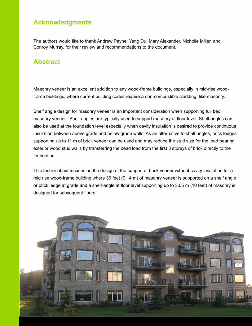
Masonry veneer is an excellent addition to any wood-frame buildings, especially in mid-rise wood-
frame buildings, where current building codes require a non-combustible cladding, like masonry.
Shelf angle design for masonry veneer is an important consideration when supporting full bed
masonry veneer. Shelf angles are typically used to support masonry at fl oor level. Shelf angles can
also be used at the foundation level especially when cavity insulation is desired to provide continuous
insulation between above grade and below grade walls. As an alternative to shelf angles, brick ledges
supporting up to 11 m of brick veneer can be used and may reduce the stud size for the load bearing
exterior wood stud walls by transferring the dead load from the fi rst 3 storeys of brick directly to the
foundation.
This technical aid focuses on the design of the support of brick veneer without cavity insulation for a
mid rise wood-frame building where 30 feet (9.14 m) of masonry veneer is supported on a shelf angle
or brick ledge at grade and a shelf-angle at fl oor level supporting up to 3.05 m (10 feet) of masonry is
designed for subsequent fl oors.
Abstract
Acknowledgments
The authors would like to thank Andrew Payne, Yang Du, Mary Alexander, Nicholle Miller, and Conroy Murray, for their review and recommendations to the document.
Shelf Angle Design at Foundation Supporting 9.144 m Brick Veneer Pg. 1
Shelf Angle Design at Floor Level Supporting 3.05 m Brick Veneer Through-bolts Pg. 3
Shelf Angle Design at Floor Level Supporting 3.05 m Brick Veneer with Lag Screws Pg. 8
Brick Ledge Design at Foundation Supporting 9.144 m Brick Veneer Pg. 12
Table of Contents
Disclaimer
This publication is intended for use by professionals who are knowledgeable and experienced in masonry and wood design and construction and who are competent to evaluate the limitations of the information provided herein. The publishers and contributors to these publications disclaim any and all responsibility and liability for the application of the information contained herein, and any injury or damages suff ered as a result of the use or inability to use this information.
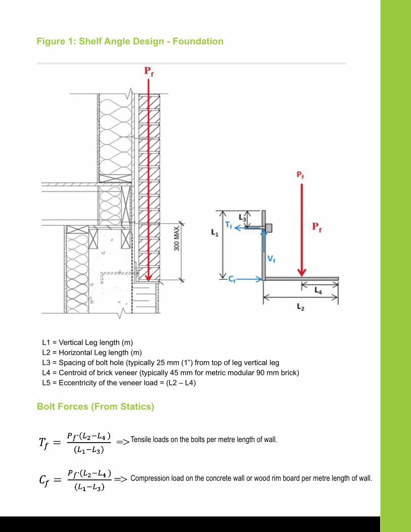
Figure 1: Shelf Angle Design - Foundation
L1 = Vertical Leg length (m)L2 = Horizontal Leg length (m)L3 = Spacing of bolt hole (typically 25 mm (1”) from top of leg vertical legL4 = Centroid of brick veneer (typically 45 mm for metric modular 90 mm brick)L5 = Eccentricity of the veneer load = (L2 – L4)
Bolt Forces (From Statics)
Tensile loads on the bolts per metre length of wall.
Compression load on the concrete wall or wood rim board per metre length of wall.
Shelf Angle Design - At Foundation
Assumptions:
• 90 mm thick brick veneer
• L152 x 102 x 9.5 (L6” x 4” x 3/8“) angle iron anchored into the concrete
• 16 mm (5/8”) Hilti Kwik Bolt 3 expansion anchor bolts at 406 mm (16”) o.c.
• Anchor bolts into a 20 MPa Concrete foundation wall
• Veneer supported to max 9.14 m (30’)
Design Forces:
i) Shelf Angle Design for Bending, Shear, and Defl ection
2
ii) Design of Concrete Anchor Bolts to Resist Shear and Withdrawal
iii) Design of Concrete Foundation to Resist Compression
Shelf Angle Design - At Floor Level
Assumptions:
• 90 mm thick brick veneer
• L203x102x6.4 (8”x4”x1/4“) angle iron anchored into the wood rim board
• Veneer supported at each fl oor - max 3.048 m (10’)
Through Bolt (RECOMMENDED)
2-ply S-P-F 2x12 rim board c/w ½” dia. (13 mm dia.) A307 through bolts at 16” (406 mm) o.c. = 2.46
bolts/m
Lag Screw (ALTERNATE SOLUTION)
3-ply SPF 2x12 rim board c/w 5/8” dia. (16 mm dia.) lag screws at 203 mm (8”) o.c.
= 4.92 lag screws/m – Minimum length of penetration into rim board for lag screws is 3-1/8” as per
CSA-O86-2014 Clause 12.6.3.3
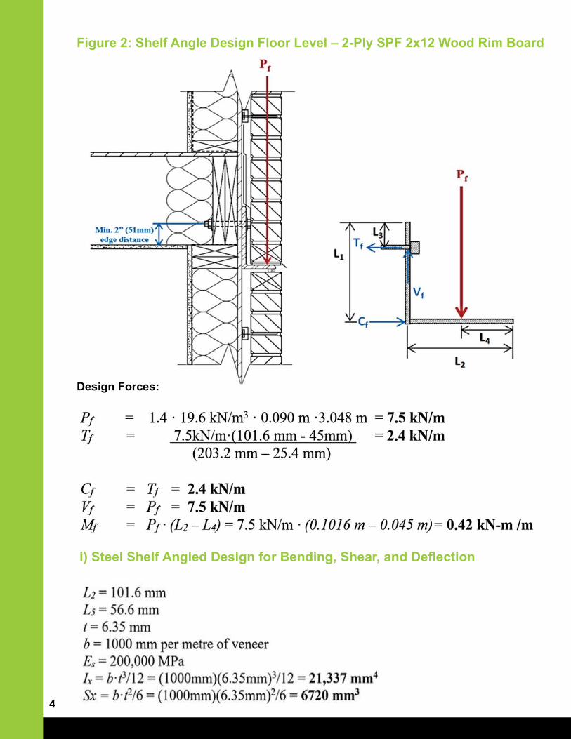
Figure 2: Shelf Angle Design Floor Level – 2-Ply SPF 2x12 Wood Rim Board
Design Forces:
i) Steel Shelf Angled Design for Bending, Shear, and Defl ection
4
Recommended Design – Through Bolt With 2-Ply SPF 2x12 Wood Rim Board
From load analysis the design loads on the fasteners are:
Tf = Tension force on through bolts per metre length of the veneer = 2.4 kN/m
Vf = Shear force on through bolts per metre length of the veneer = 7.5 kN/m
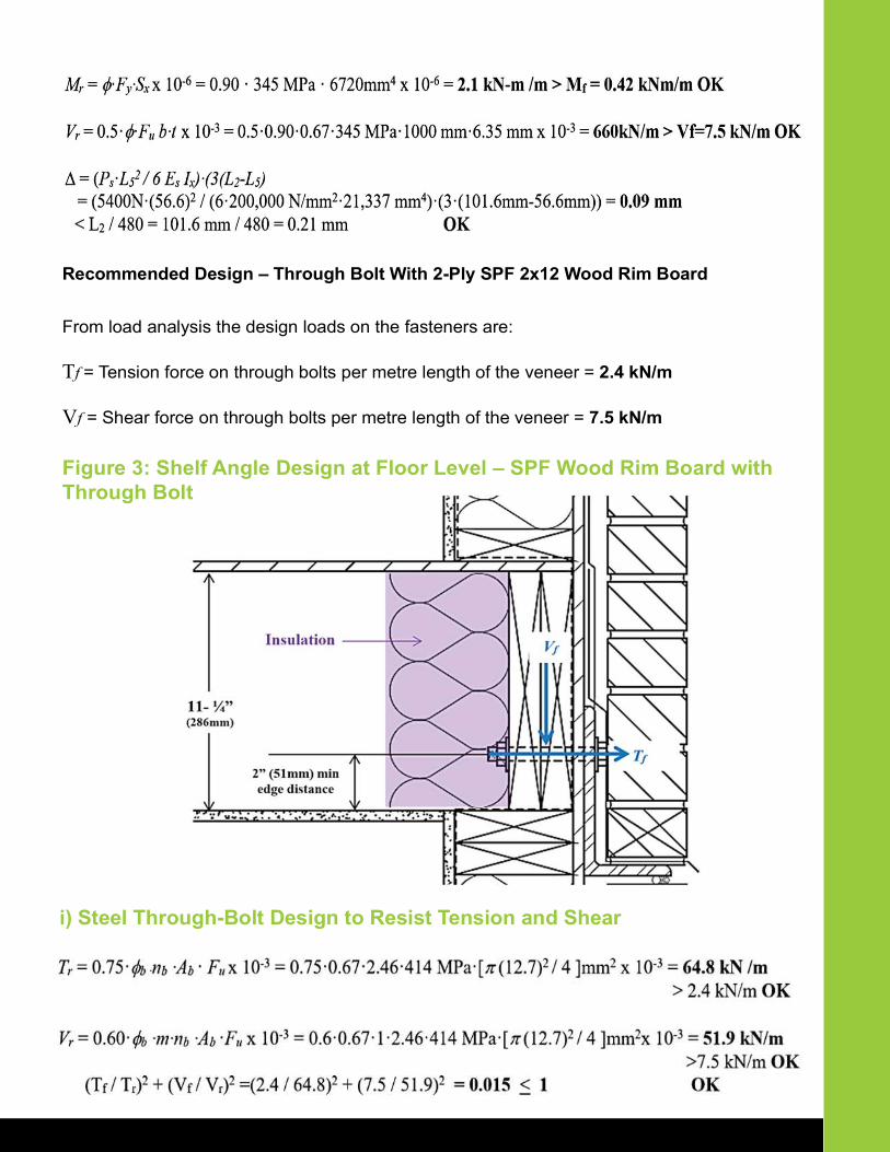
Figure 3: Shelf Angle Design at Floor Level – SPF Wood Rim Board with Through Bolt
i) Steel Through-Bolt Design to Resist Tension and Shear
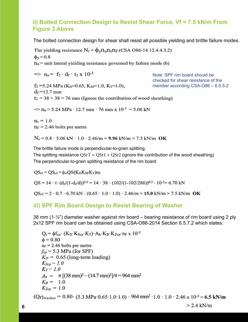
ii) Bolted Connection Design to Resist Shear Force, Vf = 7.5 kN/m From Figure 3 Above
iii) SPF Rim Board Design to Resist Bearing of Washer
38 mm (1-½”) diameter washer against rim board – bearing resistance of rim board using 2 ply 2x12 SPF rim board can be obtained using CSA-O86-2014 Section 6.5.7.2 which states:
6
The bolted connection design for shear shall resist all possible yielding and brittle failure modes.
The brittle failure mode is perpendicular-to-grain splitting.
The splitting resistance (ignore the contribution of the wood sheathing)
The perpendicular-to-grain splitting resistance of the rim board
Note: SPF rim board should be checked for shear resistance of the member according CSA-O86 – 6.5.5.2
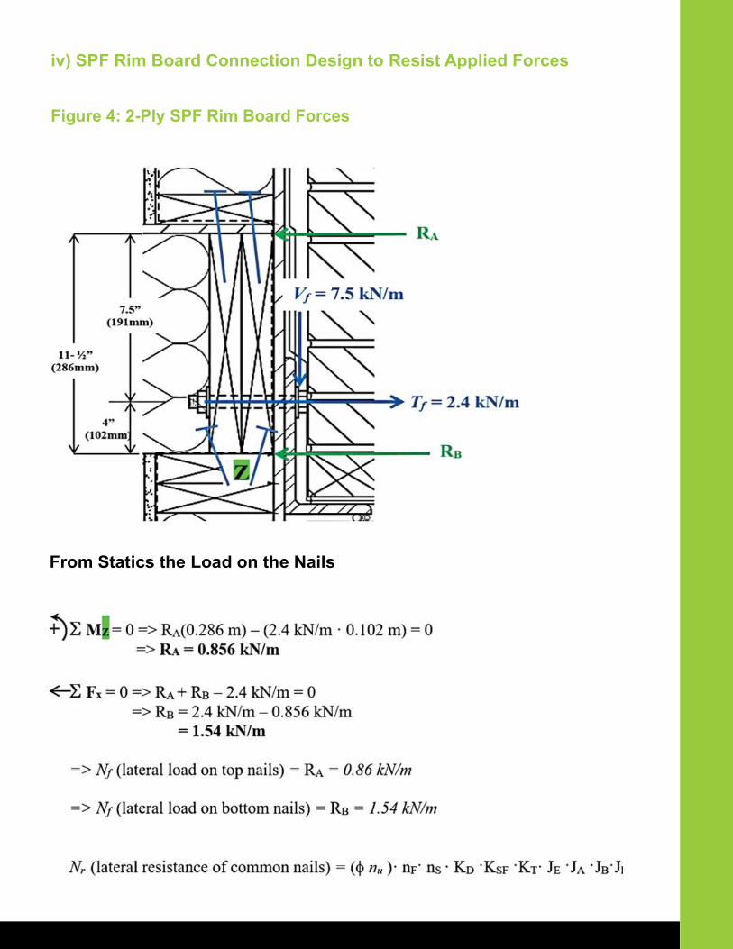
iv) SPF Rim Board Connection Design to Resist Applied Forces
From Statics the Load on the Nails
Figure 4: 2-Ply SPF Rim Board Forces
From the Canadian Wood Council’s - Wood Design Manual 2017 - Nail Selection Tables
For the connection resisting shear force RB, try 3.5” long (4.12 mm in diameter) common wire nails where toe nailing start at approximately 1/3 the nail length from the end of the piece and at an angle of 30 degree. Try two nails at every 16’’ o.c. (i.e., same location as the bolts).
The basic factored lateral resistance nu can be found from the Nail Selection Tables for a 38 mm thick SPF side member (assume the top plate of the wall assembly is constructed with SPF material). Since the penetration length into the main member is 2/3 of the nail length (greater than 33 mm).
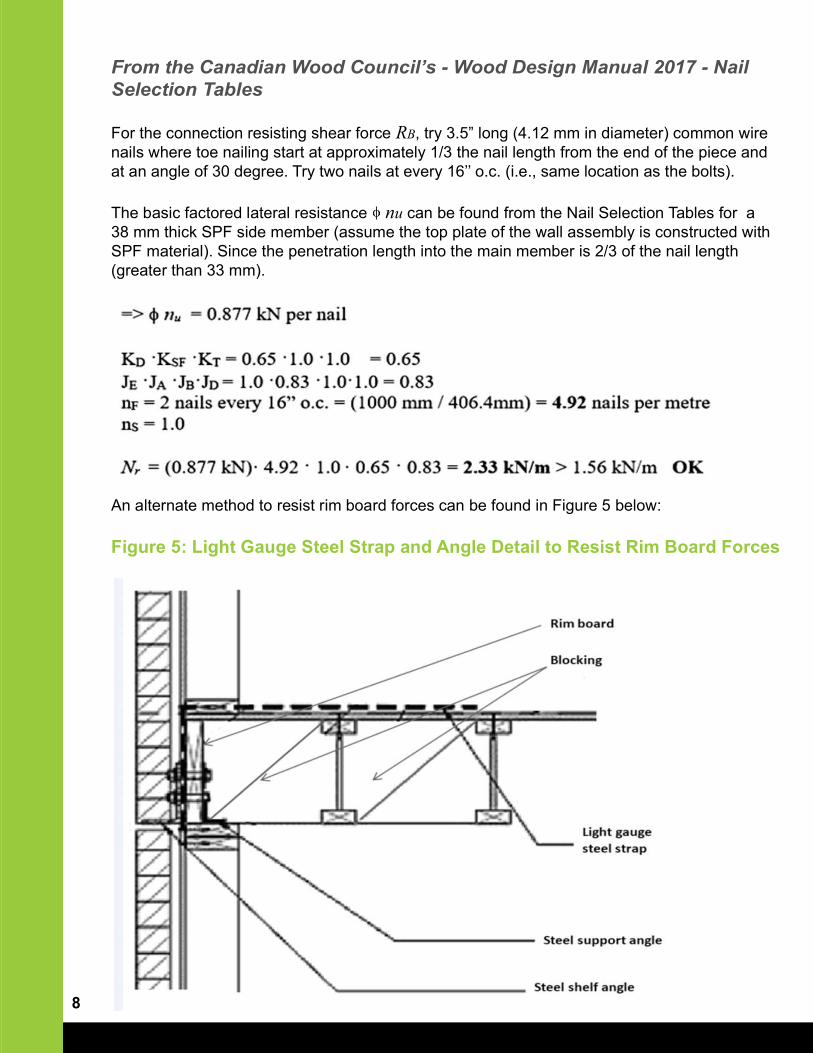
An alternate method to resist rim board forces can be found in Figure 5 below:
Figure 5: Light Gauge Steel Strap and Angle Detail to Resist Rim Board Forces
8
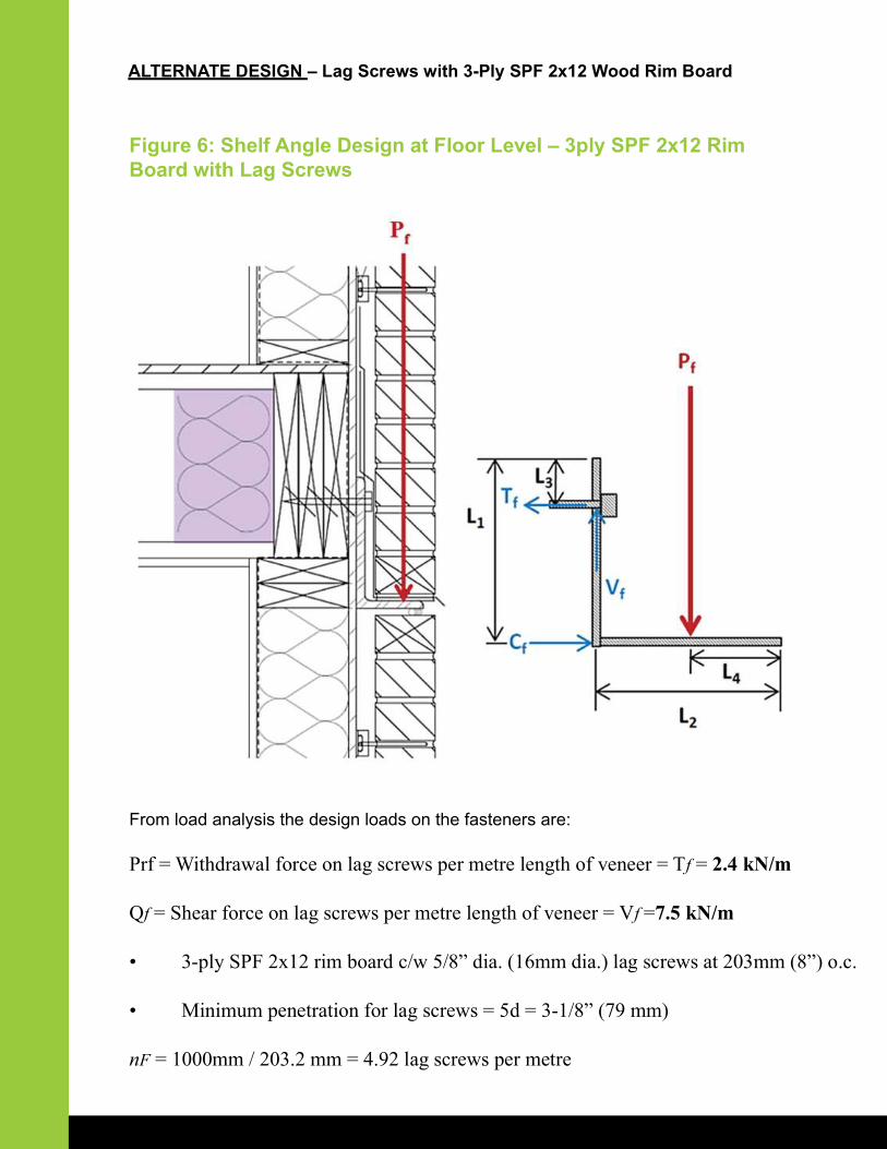
ALTERNATE DESIGN – Lag Screws with 3-Ply SPF 2x12 Wood Rim Board
Figure 6: Shelf Angle Design at Floor Level – 3ply SPF 2x12 Rim Board with Lag Screws
From load analysis the design loads on the fasteners are:
Prf = Withdrawal force on lag screws per metre length of veneer = Tf = 2.4 kN/m
Qf = Shear force on lag screws per metre length of veneer = Vf =7.5 kN/m
• 3-ply SPF 2x12 rim board c/w 5/8” dia. (16mm dia.) lag screws at 203mm (8”) o.c.
• Minimum penetration for lag screws = 5d = 3-1/8” (79 mm)
nF = 1000mm / 203.2 mm = 4.92 lag screws per metre
10
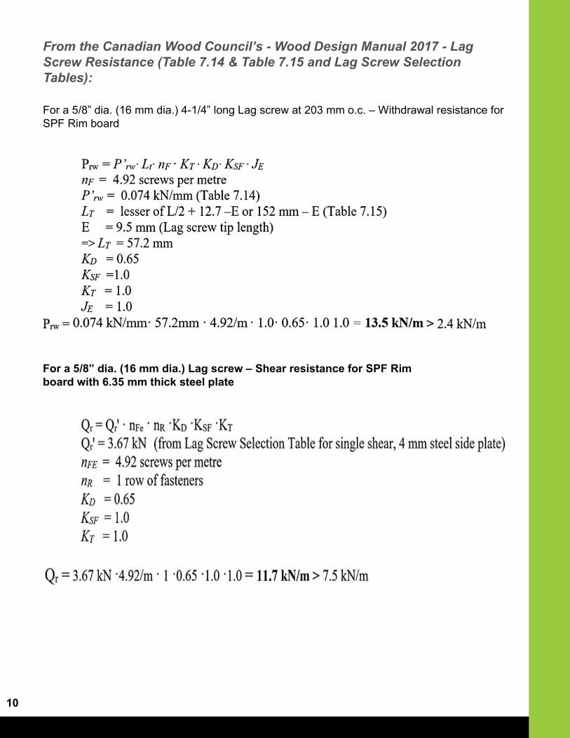
From the Canadian Wood Council’s - Wood Design Manual 2017 - Lag Screw Resistance (Table 7.14 & Table 7.15 and Lag Screw Selection Tables):
For a 5/8” dia. (16 mm dia.) Lag screw – Shear resistance for SPF Rim board with 6.35 mm thick steel plate
For a 5/8” dia. (16 mm dia.) 4-1/4” long Lag screw at 203 mm o.c. – Withdrawal resistance for SPF Rim board
Assumptions:
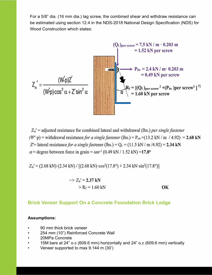
• 90 mm thick brick veneer• 254 mm (10”) Reinforced Concrete Wall• 20MPa Concrete• 15M bars at 24” o.c (609.6 mm) horizontally and 24” o.c (609.6 mm) vertically• Veneer supported to max 9.144 m (30’)
Brick Veneer Support On a Concrete Foundation Brick Ledge
For a 5/8” dia. (16 mm dia.) lag screw, the combined shear and withdraw resistance can
be estimated using section 12.4 in the NDS-2018 National Design Specifi cation (NDS) for
Wood Construction which states:
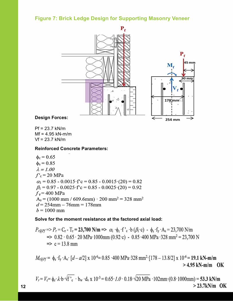
Figure 7: Brick Ledge Design for Supporting Masonry Veneer
Design Forces:
Pf = 23.7 kN/mMf = 4.95 kN-m/mVf = 23.7 kN/m
Reinforced Concrete Parameters:
Solve for the moment resistance at the factored axial load:
12


