Embed Size (px)
Citation preview
HA
KO L
EHRM
ITTE
LHAKO LehrmittelHelleräcker 6D-72127 Kusterdingen
phone +49 (0) 70 71-8 59 99 27mobile +49 (0) 1 73-9 88 64 22 fax +49 (0) 70 71-8 59 81 71e-mail: [email protected]: www.hako-lehrmittel.de
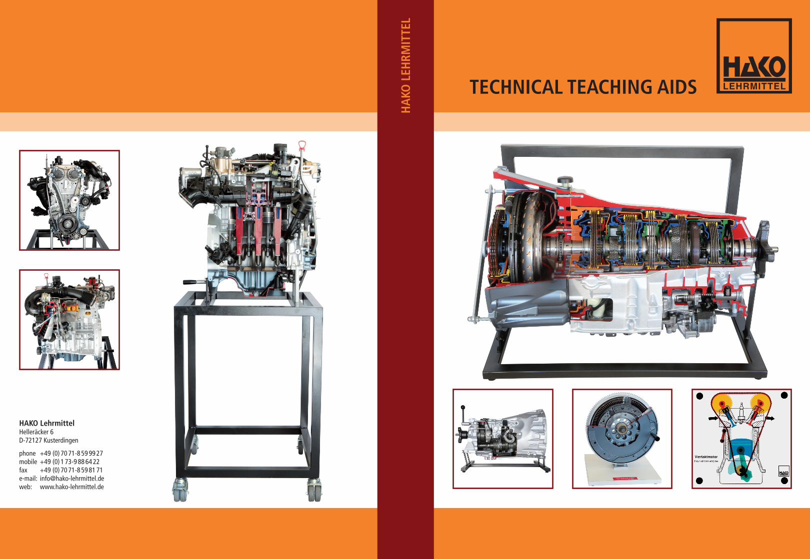
TECHNICAL TEACHING AIDS
Dear Sir/Madam
The pace of advancement in technical developments nowadays is ever increasing. The scope of the subject matter to be taught is becoming wider and more difficult, furthermore, in most cases, it has to be taught within a considerably shorter teaching period. Greater demands are continually being placed on the pubils‘capacity for intellectual thought. Consequently, there is also a growing need for the utilisation of appropriate teaching aids. The great advantage of overhead models is their ability to show key technical processes in sufficient size and action. They are ideal for de-monstrating principles and can be amplified through the addition of cutaways of the original parts.
It is important that the actual moving processes should not be demonstrated using a series of static slides, the movement action should instead be allowed to continually unfold. This improves understanding of the procedure whilst on the other hand mini-mising the amount of time required.
Years of teaching practice in vocational schools, advanced training classes and driving instruction centres led to the development of our overhead models. These models are manufactured from high quality acrylic glass, three millimetres thick and screwed together using galvanised M3 screws and washers to give you years of enjoyment. Should a model nevertheless become damaged we offer a repair service at cost price.
The baseplate on our models is 295x295x3 millimetres in size. If you experience prob-lems with storage of the models, we offer a small stand which holds 10 models and a sealed cabinet for 50 models.
Our cutaway, assembly and functional models are an ideal complement to our range of overhead models. Once the basic functional principles have been worked through using the overhead models, the cutaway original components can then be used to explain the additional functions in more detail. Our range is completed by our engine test stands for workshop use. Adjustment, testing and maintenance works can be performed on working engines, as well as troubleshooting on actuators and sensors.
We shall continue to develop further models in the future and will keep you infor-med of progress. Should you have any suggestions or technical problems concerning demonstration please let us know. We will take them on board and endeavour to seek a solution for them.
Yours sincerely HAKO Overhead Models

picture 1: positive camber picture 2: negative camber picture 3: positive kingpin offset
picture 4: negative kingpin offset picture 5: compression picture 6: rebound
HAKO-OVERHEAD-MODELS –… and what you can show with them!
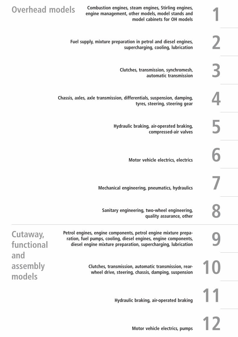
Overhead models
Cutaway, functional and assembly models
1Combustion engines, steam engines, Stirling engines,
engine management, other models, model stands and model cabinets for OH models
2Fuel supply, mixture preparation in petrol and diesel engines, supercharging, cooling, lubrication
Clutches, transmission, synchromesh, automatic transmission
Chassis, axles, axle transmission, differentials, suspension, damping, tyres, steering, steering gear
Hydraulic braking, air-operated braking, compressed-air valves
Motor vehicle electrics, electrics
Mechanical engineering, pneumatics, hydraulics
Sanitary engineering, two-wheel engineering, quality assurance, other
Petrol engines, engine components, petrol engine mixture prepa-ration, fuel pumps, cooling, diesel engines, engine components,
diesel engine mixture preparation, supercharging, lubrication
Clutches, transmission, automatic transmission, rear-wheel drive, steering, chassis, damping, suspension
Hydraulic braking, air-operated braking
Motor vehicle electrics, pumps
3456789
101112
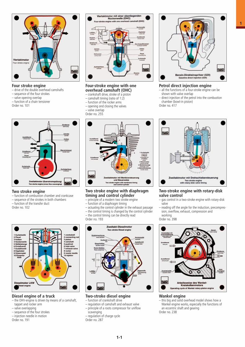
Petrol direct injection engine– all the functions of a four-stroke engine can be
shown with valve overlap– direct injection of the petrol into the combustion
chamber (bowl-in piston)Order no. 417
Two-stroke engine with rotary-disk valve control– gas control in a two-stroke engine with rotary-disk
valve– reading off the angle for the induction, precompres-
sion, overflow, exhaust, compression and working
Order no. 398
Four stroke engine– drive of the double overhead camshafts– sequence of the four strokes– valve opening overlap– function of a chain tensionerOrder no. 101
Four-stroke engine with one overhead camshaft (OHC)– crankshaft drive, stroke of a piston– camshaft timing (ratio of 1:2)– function of the rocker arms– opening ond closing the valves– valve overlapOrder no. 255
Two stroke engine– function of combustion chamber and crankcase– sequence of the strokes in both chambers– function of the transfer ductOrder no. 102
Two stroke engine with diaphragm timing and control cylinder – principle of a modern two stroke engine– function of a diaphragm timing– actuating the control cylinder in the exhaust passage– the control timing is changed by the control cylinder– the control timing can be directly readOrder no. 193
Diesel engine of a truck– the OHV-engine is driven by means of a camshaft,
tappet and rocker arm– valve overlapping– sequence of the four strokes– injection needle in motionOrder no. 191
Two-stroke diesel engine– function of crankshaft drive– regulation of camshaft and exhaust valve– principle of a roots compressor for uniflow
scavenging – regulation of charge cycleOrder no. 287
Wankel engine– this big and solid overhead model shows how a
Wankel engine works, especially the functions of an eccentric shaft and gearing
Order no. 238
1-1
1
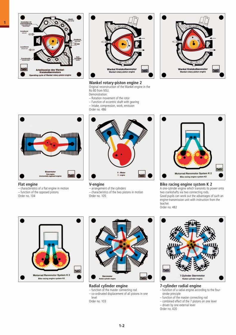
Flat engine– characteristics of a flat engine in motion– function of the opposed pistonsOrder no. 104
Radial cylinder engine– function of the master connecting rod– co-ordinated displacement of all pistons in one
levelOrder no. 103
V-engine– arrangement of the cylinders– characteristics of the two pistons in motionOrder no. 105
7-cylinder radial engine– function of a radial engine according to the four-
stroke principle– function of the master connecting rod– combined effect of the 7 pistons on one lever– driven by one external leverOrder no. 420
Wankel rotary-piston engine 2Original reconstruction of the Wankel engine in the Ro 80 from NSU.Demonstration:– Rotation movement of the rotor– Function of eccentric shaft with gearing– Intake, compression, work, emissionOrder no. 486
Bike racing engine system K 2A one-cylinder engine which transmits its power onto two crankshafts via two connecting rods. Good pupils can work out the advantages of such an engine-transmission unit with instruction from the teacher.Order no. 482
1-2
1
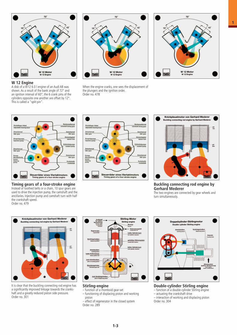
W 12 EngineA disk of a W12 6.0 l engine of an Audi A8 was shown. As a result of the bank angle of 72° and an ignition interval of 60°, the 6 crank pins of the cylinders opposite one another are offset by 12°. This is called a "split pin".
When the engine cranks, one sees the displacement of the plungers and the ignition order.Order no. 478
Timing gears of a four-stroke engineInstead of toothed belts or a chain, 10 spur gears are used to drive the injection pump, the camshaft and the ancillaries. Injection pump and camshaft turn with half the crankshaft speed.Order no. 479
Buckling connecting rod engine by Gerhard MedererThe two engines are connected by gear wheels and turn simultaneously.
It is clear that the buckling connecting rod engine has a significantly improved linkage towards the cranks-haft and a greatly reduced piston side pressure.Order no. 301
Stirling-engine– function of a rhomboid gear-set– functioning of displacing piston and working
piston– effect of regenerator in the closed systemOrder no. 289
Double-cylinder Stirling engine– function of a double-cylinder Stirling engine– actuating the crankshaft drive– interaction of working and displacing pistonOrder no. 304
1-3
1
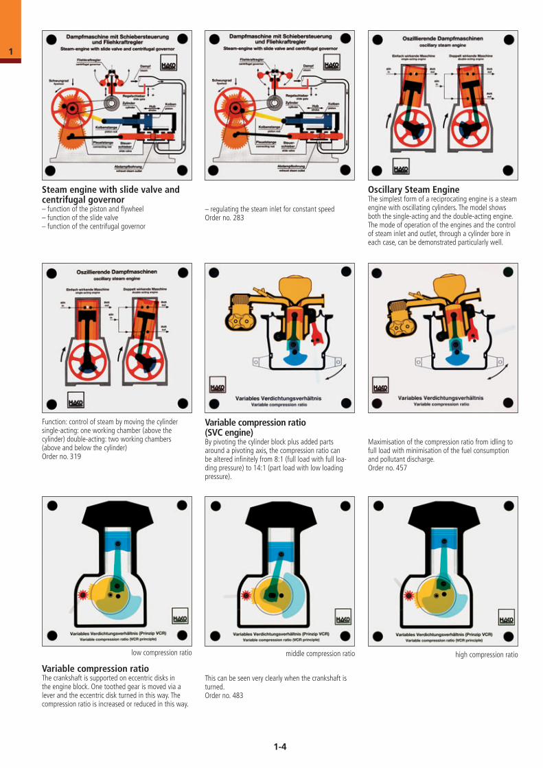
Oscillary Steam EngineThe simplest form of a reciprocating engine is a steam engine with oscillating cylinders. The model shows both the single-acting and the double-acting engine. The mode of operation of the engines and the control of steam inlet and outlet, through a cylinder bore in each case, can be demonstrated particularly well.
Function: control of steam by moving the cylindersingle-acting: one working chamber (above the cylinder) double-acting: two working chambers (above and below the cylinder)Order no. 319
Variable compression ratio (SVC engine)By pivoting the cylinder block plus added parts around a pivoting axis, the compression ratio can be altered infinitely from 8:1 (full load with full loa-ding pressure) to 14:1 (part load with low loading pressure).
Maximisation of the compression ratio from idling to full load with minimisation of the fuel consumption and pollutant discharge.Order no. 457
Variable compression ratio The crankshaft is supported on eccentric disks in the engine block. One toothed gear is moved via a lever and the eccentric disk turned in this way. The compression ratio is increased or reduced in this way.
This can be seen very clearly when the crankshaft is turned.Order no. 483
low compression ratio middle compression ratio high compression ratio
Steam engine with slide valve and centrifugal governor– function of the piston and flywheel– function of the slide valve – function of the centrifugal governor
– regulating the steam inlet for constant speedOrder no. 283
1-4
1
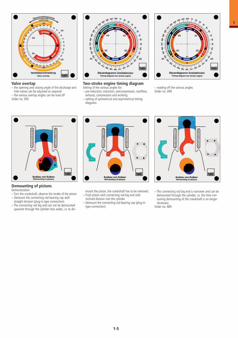
Valve overlap– the opening and closing angle of the discharge and
inlet valves can be adjusted as required– the various overlap angles can be read offOrder no. 395
Two-stroke engine timing diagramSetting of the various angles for:– pre-induction, induction, precompression, overflow,
exhaust, compression and working– setting of symmetrical and asymmetrical timing
diagrams
– reading off the various anglesOrder no. 399
Demounting of pistonsDemonstration:– Turn the crankshaft, observe the stroke of the piston– Demount the connecting rod bearing cap with
straight division (plug-in type connection).– The connecting rod big end can not be demounted
upwards through the cylinder (too wide), i.e. to dis-
mount the piston, the crankshaft has to be removed.– Push piston with connecting rod big end with
inclined division into the cylinder – Demount the connecting rod bearing cap (plug-in
type connection).
– This connecting rod big end is narrower and can be demounted through the cylinder, i.e. the time-con-suming demounting of the crankshaft is no longer necessary.
Order no. 485
1-5
1
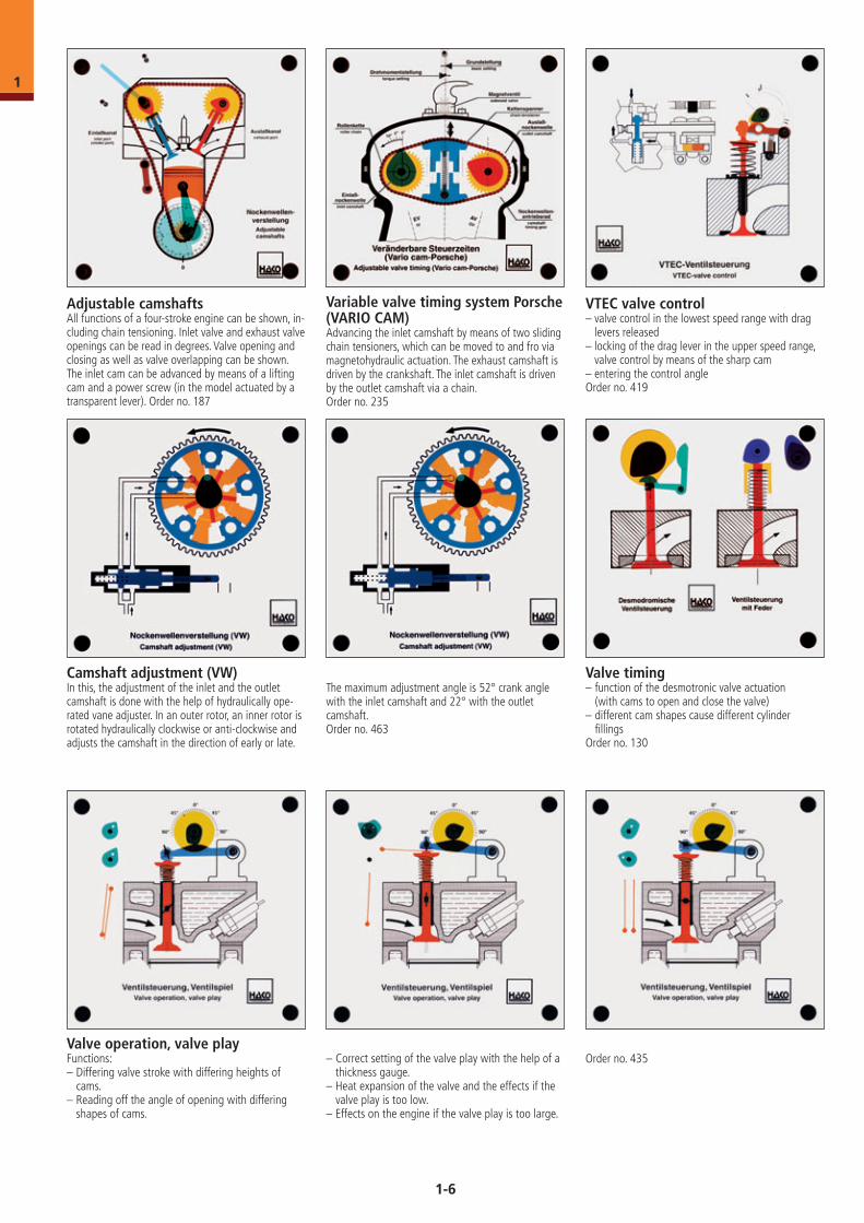
Adjustable camshaftsAll functions of a four-stroke engine can be shown, in-cluding chain tensioning. Inlet valve and exhaust valve openings can be read in degrees. Valve opening and closing as well as valve overlapping can be shown. The inlet cam can be advanced by means of a lifting cam and a power screw (in the model actuated by a transparent lever). Order no. 187
Variable valve timing system Porsche (VARIO CAM)Advancing the inlet camshaft by means of two sliding chain tensioners, which can be moved to and fro via magnetohydraulic actuation. The exhaust camshaft is driven by the crankshaft. The inlet camshaft is driven by the outlet camshaft via a chain.Order no. 235
Valve timing– function of the desmotronic valve actuation (with cams to open and close the valve)– different cam shapes cause different cylinder fillingsOrder no. 130
VTEC valve control– valve control in the lowest speed range with drag
levers released– locking of the drag lever in the upper speed range,
valve control by means of the sharp cam– entering the control angleOrder no. 419
Valve operation, valve play Functions:– Differing valve stroke with differing heights of
cams.– Reading off the angle of opening with differing
shapes of cams.
– Correct setting of the valve play with the help of a thickness gauge.
– Heat expansion of the valve and the effects if the valve play is too low.
– Effects on the engine if the valve play is too large.
Order no. 435
Camshaft adjustment (VW)In this, the adjustment of the inlet and the outlet camshaft is done with the help of hydraulically ope-rated vane adjuster. In an outer rotor, an inner rotor is rotated hydraulically clockwise or anti-clockwise and adjusts the camshaft in the direction of early or late.
The maximum adjustment angle is 52° crank angle with the inlet camshaft and 22° with the outlet camshaft.Order no. 463
1-6
1
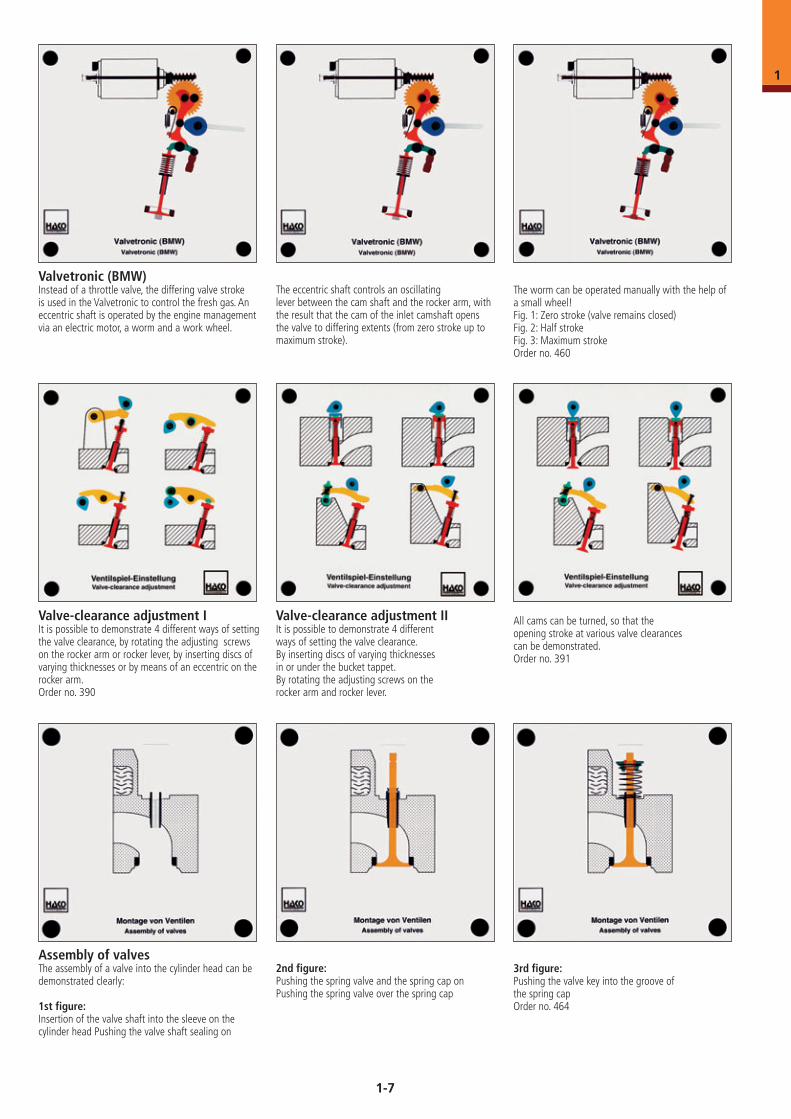
Valve-clearance adjustment IIt is possible to demonstrate 4 different ways of setting the valve clearance, by rotating the adjusting screws on the rocker arm or rocker lever, by inserting discs of varying thicknesses or by means of an eccentric on the rocker arm.Order no. 390
Valve-clearance adjustment IIIt is possible to demonstrate 4 differentways of setting the valve clearance.By inserting discs of varying thicknessesin or under the bucket tappet.By rotating the adjusting screws on the rocker arm and rocker lever.
All cams can be turned, so that the opening stroke at various valve clearances can be demonstrated.Order no. 391
Valvetronic (BMW)Instead of a throttle valve, the differing valve stroke is used in the Valvetronic to control the fresh gas. An eccentric shaft is operated by the engine management via an electric motor, a worm and a work wheel.
The eccentric shaft controls an oscillating lever between the cam shaft and the rocker arm, with the result that the cam of the inlet camshaft opens the valve to differing extents (from zero stroke up to maximum stroke).
The worm can be operated manually with the help of a small wheel!Fig. 1: Zero stroke (valve remains closed) Fig. 2: Half strokeFig. 3: Maximum strokeOrder no. 460
Assembly of valvesThe assembly of a valve into the cylinder head can be demonstrated clearly:
1st figure: Insertion of the valve shaft into the sleeve on the cylinder head Pushing the valve shaft sealing on
2nd figure: Pushing the spring valve and the spring cap onPushing the spring valve over the spring cap
3rd figure: Pushing the valve key into the groove of the spring capOrder no. 464
1-7
1
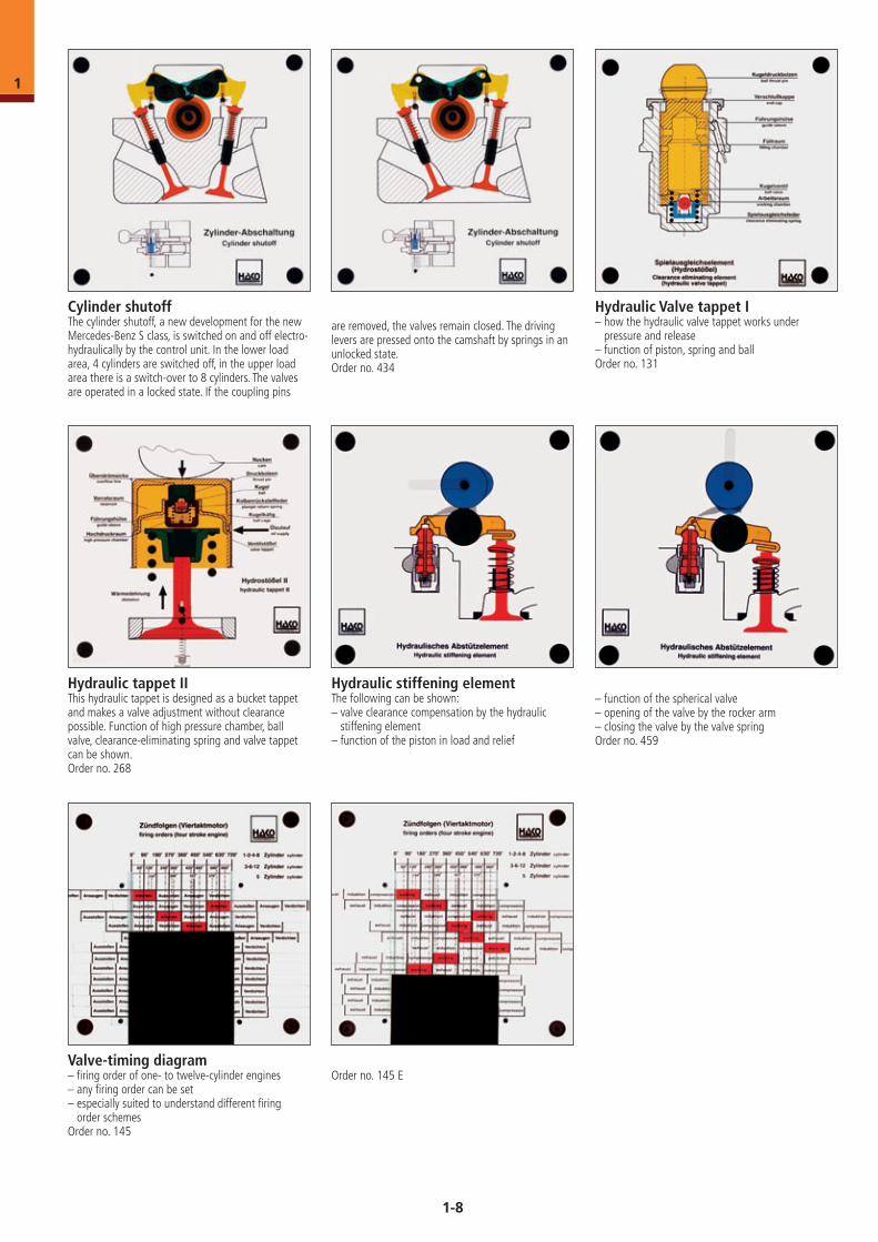
Hydraulic stiffening elementThe following can be shown: – valve clearance compensation by the hydraulic
stiffening element– function of the piston in load and relief
– function of the spherical valve– opening of the valve by the rocker arm– closing the valve by the valve springOrder no. 459
Cylinder shutoffThe cylinder shutoff, a new development for the new Mercedes-Benz S class, is switched on and off electro-hydraulically by the control unit. In the lower load area, 4 cylinders are switched off, in the upper load area there is a switch-over to 8 cylinders. The valves are operated in a locked state. If the coupling pins
are removed, the valves remain closed. The driving levers are pressed onto the camshaft by springs in an unlocked state.Order no. 434
Hydraulic Valve tappet I– how the hydraulic valve tappet works under
pressure and release – function of piston, spring and ballOrder no. 131
Valve-timing diagram– firing order of one- to twelve-cylinder engines– any firing order can be set– especially suited to understand different firing
order schemesOrder no. 145
Order no. 145 E
Hydraulic tappet IIThis hydraulic tappet is designed as a bucket tappet and makes a valve adjustment without clearance possible. Function of high pressure chamber, ball valve, clearance-eliminating spring and valve tappet can be shown.Order no. 268
1-8
1
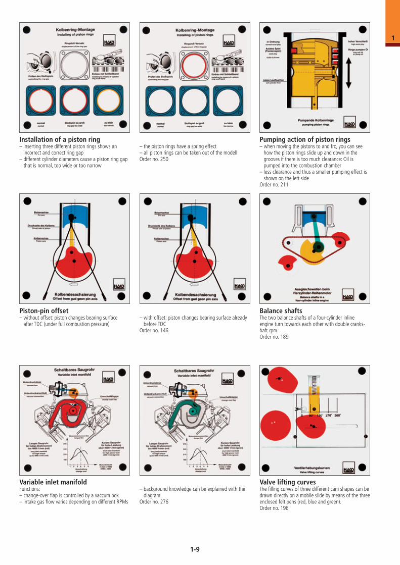
Installation of a piston ring– inserting three different piston rings shows an
incorrect and correct ring gap– different cylinder diameters cause a piston ring gap
that is normal, too wide or too narrow
– the piston rings have a spring effect– all piston rings can be taken out of the modellOrder no. 250
Pumping action of piston rings– when moving the pistons to and fro, you can see
how the piston rings slide up and down in the grooves if there is too much clearance: Oil is pumped into the combustion chamber
– less clearance and thus a smaller pumping effect is shown on the left side
Order no. 211
Piston-pin offset– without offset: piston changes bearing surface
after TDC (under full combustion pressure)
Balance shaftsThe two balance shafts of a four-cylinder inline engine turn towards each other with double cranks-haft rpm.Order no. 189
Valve lifting curvesThe filling curves of three different cam shapes can be drawn directly on a mobile slide by means of the three enclosed felt pens (red, blue and green).Order no. 196
Variable inlet manifoldFunctions:– change-over flap is controlled by a vaccum box– intake gas flow varies depending on different RPMs
– with offset: piston changes bearing surface already before TDC
Order no. 146
– background knowledge can be explained with the diagram
Order no. 276
1-9
1
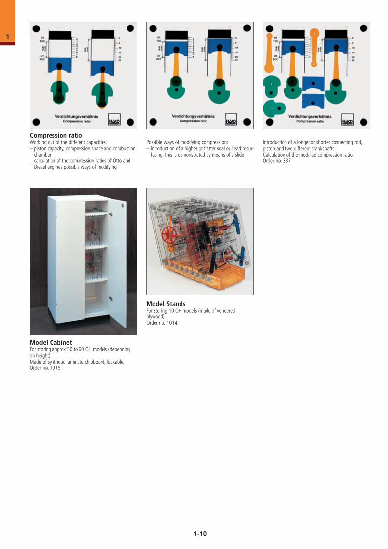
Compression ratioWorking out of the different capacities:– piston capacity, compression space and combustion
chamber– calculation of the compression ratios of Otto and
Diesel engines possible ways of modifying
Possible ways of modifying compression:– introduction of a higher or flatter seal or head resur-
facing; this is demonstrated by means of a slide
Introduction of a longer or shorter connecting rod, piston and two different crankshafts. Calculation of the modified compression ratio.Order no. 337
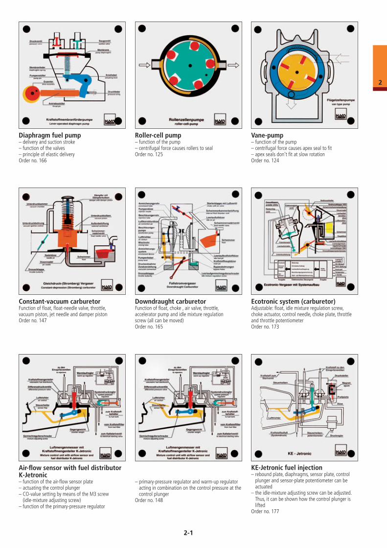
Model CabinetFor storing approx 50 to 60 OH models (depending on height).Made of synthetic laminate chipboard, lockable.Order no. 1015
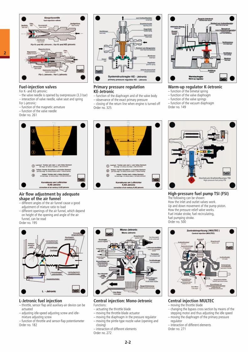
Model StandsFor storing 10 OH models (made of veneered plywood)Order no. 1014
1-10
1
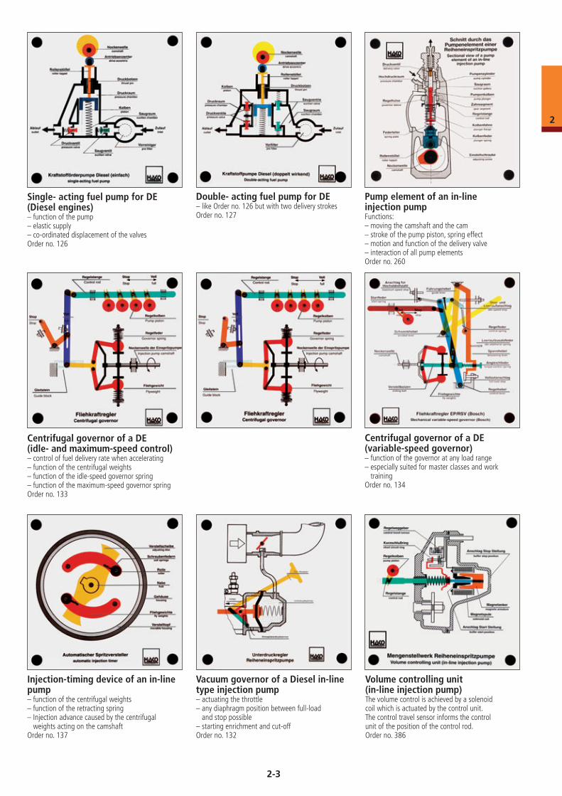
Diaphragm fuel pump– delivery and suction stroke– function of the valves– principle of elastic deliveryOrder no. 166
Roller-cell pump– function of the pump– centrifugal force causes rollers to sealOrder no. 125
Vane-pump– function of the pump– centrifugal force causes apex seal to fit– apex seals don’t fit at slow rotationOrder no. 124
Constant-vacuum carburetorFunction of float, float-needle valve, throttle, vacuum piston, jet needle and damper pistonOrder no. 147
Ecotronic system (carburetor)Adjustable: float, idle mixture regulation screw, choke actuator, control needle, choke plate, throttle and throttle potentiometerOrder no. 173
Downdraught carburetorFunction of float, choke , air valve, throttle, accelerator pump and idle mixture regulation screw (all can be moved)Order no. 165
Air-flow sensor with fuel distributor K-Jetronic– function of the air-flow sensor plate– actuating the control plunger– CO-value setting by means of the M3 screw
(idle-mixture adjusting screw)– function of the primary-pressure regulator
– primary-pressure regulator and warm-up regulator acting in combination on the control pressure at the control plunger
Order no. 148
KE-Jetronic fuel injection– rebound plate, diaphragms, sensor plate, control
plunger and sensor-plate potentiometer can be actuated
– the idle-mixture adjusting screw can be adjusted. Thus, it can be shown how the control plunger is lifted
Order no. 177
2-1
2
Fuel-injection valvesFor K- and KE-jetronic:– the valve needle is opened by overpressure (3.3 bar)– interaction of valve needle, valve seat and spring For L-jetronic:– function of the magnetic armature– function of the valve needleOrder no. 261
Primary pressure regulation KE-Jetronic– function of the diaphragm and of the valve body– observance of the exact primary pressure – closing of the return line when engine is turned offOrder no. 325
Central injection MULTEC– moving the throttle blade– changing the bypass cross section by means of the
stepping motor and thus adjusting the idle speed– moving the diaphragm of the primary pressure
regulator– interaction of different elementsOrder no. 271
Warm-up regulator K-Jetronic– function of the bimetal spring– function of the valve diaphragm– function of the valve springs– function of the vacuum diaphragmOrder no. 149
Air flow adjustment by adequate shape of the air funnel– different angles of the air funnel cause a good
adjustment of mixture ratio to load– different openings of the air funnel, which depend
on height of the opening and angle of the air funnel, can be read
Order no. 195
L-Jetronic fuel injection– throttle, sensor flap and auxiliary-air device can be
actuated– adjusting idle-speed adjusting screw and idle-
mixture adjusting screw– function of throttle and sensor-flap potentiometerOrder no. 182
Central injection: Mono-Jetronic Functions:– actuating the throttle blade– moving the throttle-blade actuator– moving the diaphragm in the pressure regulator– moving the pintle-type nozzle valve (opening and
closing)– interaction of different elementsOrder no. 272
High-pressure fuel pump TSI (FSI)The following can be shown: How the inlet and outlet valves work. Up and down movement of the pump piston. How the pressure relief valve works. Fuel intake stroke, fuel recirculating, fuel pumping stroke.Order no. 500
2-2
2
Double- acting fuel pump for DE– like Order no. 126 but with two delivery strokesOrder no. 127
Pump element of an in-line injection pumpFunctions:– moving the camshaft and the cam– stroke of the pump piston, spring effect– motion and function of the delivery valve– interaction of all pump elementsOrder no. 260
Single- acting fuel pump for DE (Diesel engines)– function of the pump– elastic supply– co-ordinated displacement of the valvesOrder no. 126
Centrifugal governor of a DE (idle- and maximum-speed control)– control of fuel delivery rate when accelerating– function of the centrifugal weights– function of the idle-speed governor spring– function of the maximum-speed governor springOrder no. 133
Centrifugal governor of a DE (variable-speed governor)– function of the governor at any load range– especially suited for master classes and work
trainingOrder no. 134
Injection-timing device of an in-line pump– function of the centrifugal weights– function of the retracting spring– Injection advance caused by the centrifugal
weights acting on the camshaftOrder no. 137
Vacuum governor of a Diesel in-line type injection pump– actuating the throttle– any diaphragm position between full-load
and stop possible– starting enrichment and cut-offOrder no. 132
Volume controlling unit (in-line injection pump)The volume control is achieved by a solenoidcoil which is actuated by the control unit. The control travel sensor informs the control unit of the position of the control rod.Order no. 386
2-3
2
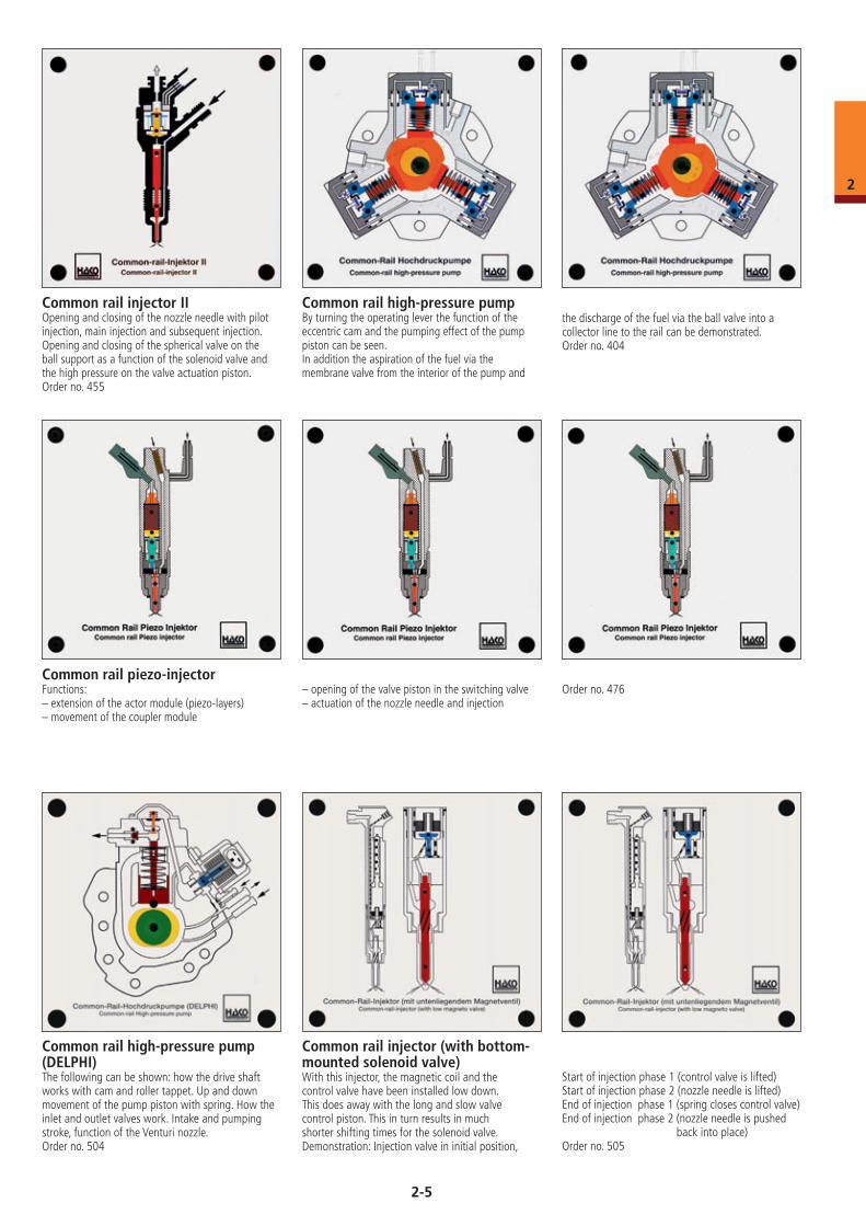
Two-spring injection-nozzle with needle-displacement sensor– low fuel injection (the valve needle is lifted
against the weak spring # 1)– high fuel injection (the valve needle is lifted
against stiff spring # 2)– the needle-displacement sensor senses start of
injection Order no. 291
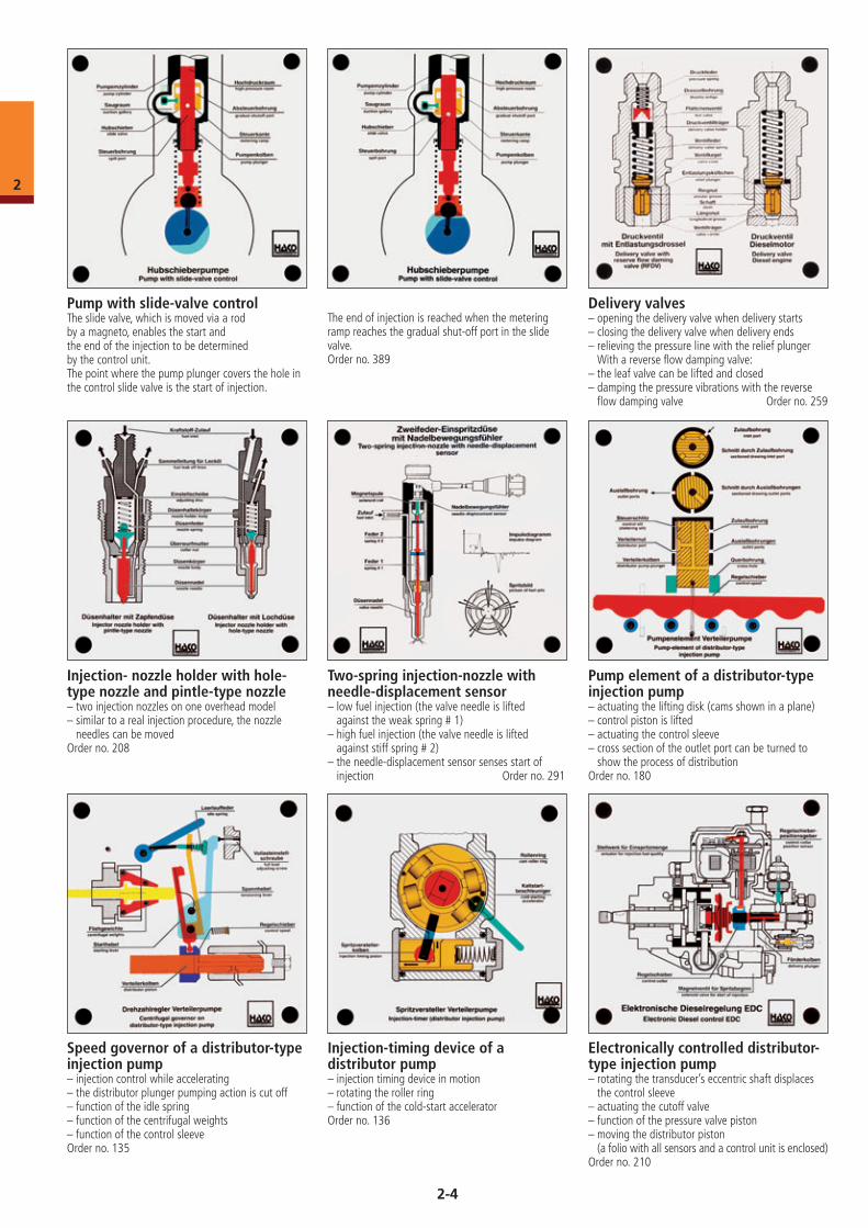
Pump with slide-valve controlThe slide valve, which is moved via a rod by a magneto, enables the start andthe end of the injection to be determined by the control unit.The point where the pump plunger covers the hole in the control slide valve is the start of injection.
The end of injection is reached when the metering ramp reaches the gradual shut-off port in the slide valve.Order no. 389
Delivery valves– opening the delivery valve when delivery starts– closing the delivery valve when delivery ends– relieving the pressure line with the relief plunger
With a reverse flow damping valve:– the leaf valve can be lifted and closed– damping the pressure vibrations with the reverse
flow damping valve Order no. 259
Injection- nozzle holder with hole- type nozzle and pintle-type nozzle– two injection nozzles on one overhead model– similar to a real injection procedure, the nozzle
needles can be movedOrder no. 208
Pump element of a distributor-type injection pump– actuating the lifting disk (cams shown in a plane)– control piston is lifted– actuating the control sleeve– cross section of the outlet port can be turned to
show the process of distributionOrder no. 180
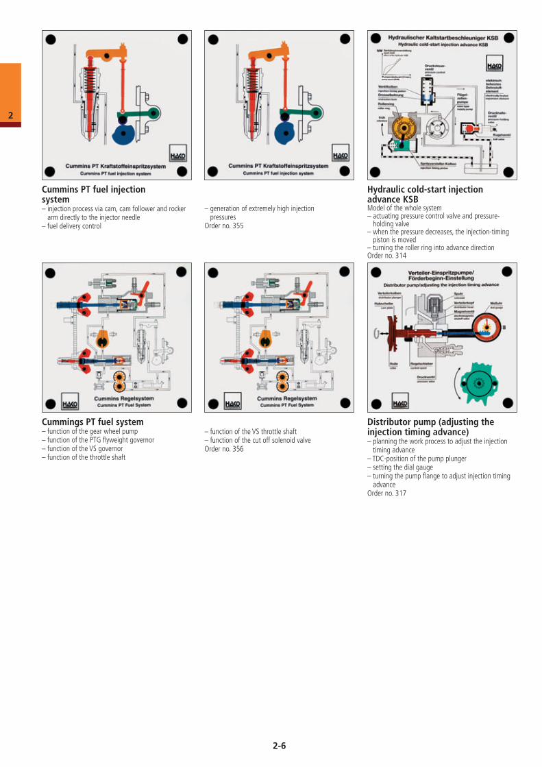
Injection-timing device of a distributor pump– injection timing device in motion– rotating the roller ring– function of the cold-start acceleratorOrder no. 136
Electronically controlled distributor- type injection pump– rotating the transducer’s eccentric shaft displaces
the control sleeve– actuating the cutoff valve– function of the pressure valve piston– moving the distributor piston
(a folio with all sensors and a control unit is enclosed)Order no. 210
Speed governor of a distributor-type injection pump– injection control while accelerating– the distributor plunger pumping action is cut off– function of the idle spring– function of the centrifugal weights– function of the control sleeveOrder no. 135
2-4
2
Common rail high-pressure pump By turning the operating lever the function of the eccentric cam and the pumping effect of the pump piston can be seen.In addition the aspiration of the fuel via the membrane valve from the interior of the pump and
the discharge of the fuel via the ball valve into a collector line to the rail can be demonstrated.Order no. 404
Common rail injector IIOpening and closing of the nozzle needle with pilot injection, main injection and subsequent injection. Opening and closing of the spherical valve on the ball support as a function of the solenoid valve and the high pressure on the valve actuation piston.Order no. 455
Common rail piezo-injectorFunctions:– extension of the actor module (piezo-layers)– movement of the coupler module
– opening of the valve piston in the switching valve– actuation of the nozzle needle and injection
Order no. 476
Start of injection phase 1 (control valve is lifted)Start of injection phase 2 (nozzle needle is lifted)End of injection phase 1 (spring closes control valve)End of injection phase 2 (nozzle needle is pushed back into place)Order no. 505
Common rail injector (with bottom-mounted solenoid valve)With this injector, the magnetic coil and the control valve have been installed low down. This does away with the long and slow valve control piston. This in turn results in much shorter shifting times for the solenoid valve. Demonstration: Injection valve in initial position,
Common rail high-pressure pump (DELPHI)The following can be shown: how the drive shaft works with cam and roller tappet. Up and down movement of the pump piston with spring. How the inlet and outlet valves work. Intake and pumping stroke, function of the Venturi nozzle.Order no. 504
2-5
2
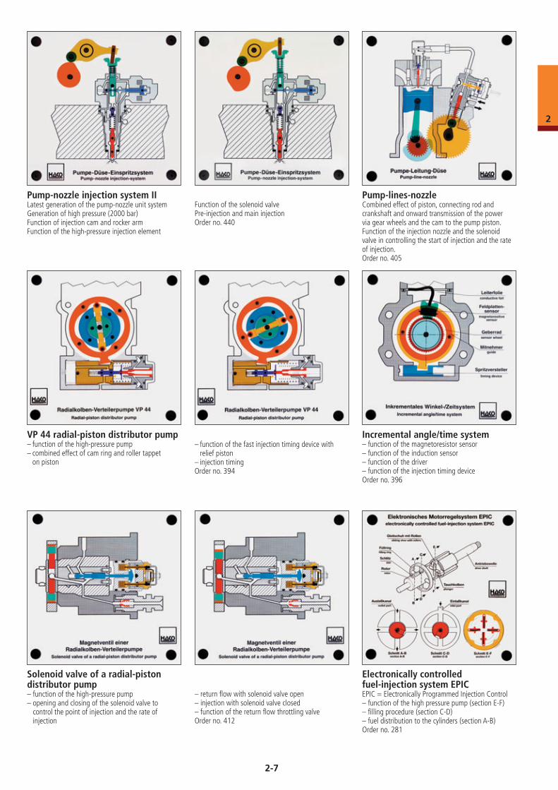
Cummins PT fuel injection system– injection process via cam, cam follower and rocker
arm directly to the injector needle– fuel delivery control
– generation of extremely high injection pressures
Order no. 355
Hydraulic cold-start injection advance KSBModel of the whole system – actuating pressure control valve and pressure-
holding valve– when the pressure decreases, the injection-timing
piston is moved– turning the roller ring into advance directionOrder no. 314
Cummings PT fuel system– function of the gear wheel pump– function of the PTG flyweight governor– function of the VS governor– function of the throttle shaft
Distributor pump (adjusting the injection timing advance)– planning the work process to adjust the injection
timing advance– TDC-position of the pump plunger– setting the dial gauge– turning the pump flange to adjust injection timing
advanceOrder no. 317
– function of the VS throttle shaft– function of the cut off solenoid valveOrder no. 356
2-6
2
Pump-nozzle injection system IILatest generation of the pump-nozzle unit systemGeneration of high pressure (2000 bar) Function of injection cam and rocker armFunction of the high-pressure injection element
Function of the solenoid valvePre-injection and main injection Order no. 440
Pump-lines-nozzleCombined effect of piston, connecting rod and crankshaft and onward transmission of the power via gear wheels and the cam to the pump piston. Function of the injection nozzle and the solenoid valve in controlling the start of injection and the rateof injection. Order no. 405
Electronically controlled fuel-injection system EPICEPIC = Electronically Programmed Injection Control– function of the high pressure pump (section E-F)– filling procedure (section C-D)– fuel distribution to the cylinders (section A-B)Order no. 281
VP 44 radial-piston distributor pump– function of the high-pressure pump– combined effect of cam ring and roller tappet
on piston
– function of the fast injection timing device with relief piston
– injection timingOrder no. 394
Solenoid valve of a radial-piston distributor pump– function of the high-pressure pump– opening and closing of the solenoid valve to
control the point of injection and the rate of injection
– return flow with solenoid valve open– injection with solenoid valve closed– function of the return flow throttling valveOrder no. 412
Incremental angle/time system– function of the magnetoresistor sensor– function of the induction sensor – function of the driver– function of the injection timing deviceOrder no. 396
2-7
2
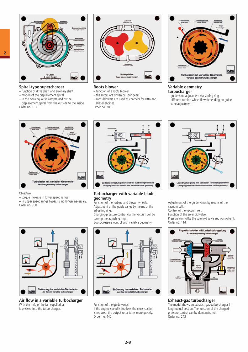
Spiral-type supercharger– function of drive shaft and auxiliary shaft– motion of the displacement spiral– in the housing, air is compressed by the
displacement spiral from the outside to the insideOrder no. 161
Roots blower– function of a roots blower– the rotors are driven by spur gears– roots blowers are used as chargers for Otto and
Diesel enginesOrder no. 205
Variable geometry turbocharger– guide vane adjustment via setting ring– different turbine wheel flow depending on guide
vane adjustment
Objective: – torque increase in lower speed range– in upper speed range bypass is no longer necessary.Order no. 358
Turbocharger with variable blade geometryFunction of the turbine and blower wheels.Adjustment of the guide vanes by means of the adjusting ring.Charging-pressure control via the vacuum cell by turning the adjusting ring.Boost-pressure control with variable geometry.
Adjustment of the guide vanes by means of the vacuum cell.Control of the vacuum cell.Function of the solenoid valve.Pressure control by the solenoid valve and control unit.Order no. 414
Exhaust-gas turbochargerThe model shows an exhaust-gas-turbo-charger in longitudiual section. The function of the charged-pressure control can be demonstrated.Order no. 243
Air flow in a variable turbochargerWith the help of the fan supplied, airis pressed into the turbo-charger.
Function of the guide vanes:if the engine speed is too low, the cross-sectionis reduced, the output rotor turns more quickly.Order no. 442
2-8
2
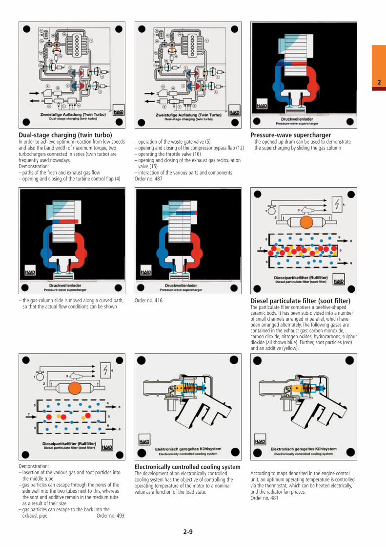
Pressure-wave supercharger– the opened-up drum can be used to demonstrate
the supercharging by sliding the gas column
– the gas-column slide is moved along a curved path, so that the actual flow conditions can be shown
Order no. 416
Dual-stage charging (twin turbo)In order to achieve optimum reaction from low speeds and also the band width of maximum torque, two turbochargers connected in series (twin turbo) are frequently used nowadays.Demonstration:– paths of the fresh and exhaust gas flow– opening and closing of the turbine control flap (4)
– operation of the waste gate valve (5)– opening and closing of the compressor bypass flap (12)– operating the throttle valve (16)– opening and closing of the exhaust gas recirculation
valve (15)– interaction of the various parts and componentsOrder no. 487
Diesel particulate filter (soot filter)The particulate filter comprises a beehive-shaped ceramic body. It has been sub-divided into a number of small channels arranged in parallel, which have been arranged alternately. The following gases are contained in the exhaust gas: carbon monoxide, carbon dioxide, nitrogen oxides, hydrocarbons, sulphur dioxide (all shown blue). Further, soot particles (red) and an additive (yellow).
Demonstration: – insertion of the various gas and soot particles into
the middle tube– gas particles can escape through the pores of the
side wall into the two tubes next to this, whereas the soot and additive remain in the medium tube as a result of their size
– gas particles can escape to the back into the exhaust pipe Order no. 493
Electronically controlled cooling systemThe development of an electronically controlled cooling system has the objective of controlling the operating temperature of the motor to a nominal value as a function of the load state.
According to maps deposited in the engine control unit, an optimum operating temperature is controlled via the thermostat, which can be heated electrically, and the radiator fan phases. Order no. 481
2-9
2
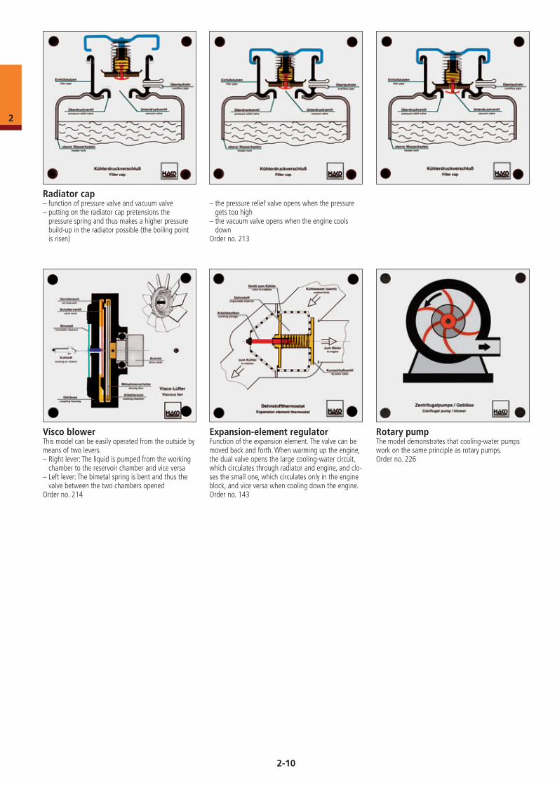
Radiator cap– function of pressure valve and vacuum valve– putting on the radiator cap pretensions the
pressure spring and thus makes a higher pressure build-up in the radiator possible (the boiling point is risen)
– the pressure relief valve opens when the pressure gets too high
– the vacuum valve opens when the engine cools down
Order no. 213
Rotary pumpThe model demonstrates that cooling-water pumps work on the same principle as rotary pumps.Order no. 226
Expansion-element regulatorFunction of the expansion element. The valve can be moved back and forth. When warming up the engine, the dual valve opens the large cooling-water circuit, which circulates through radiator and engine, and clo-ses the small one, which circulates only in the engine block, and vice versa when cooling down the engine.Order no. 143
Visco blowerThis model can be easily operated from the outside by means of two levers.– Right lever: The liquid is pumped from the working
chamber to the reservoir chamber and vice versa– Left lever: The bimetal spring is bent and thus the
valve between the two chambers openedOrder no. 214
2-10
2
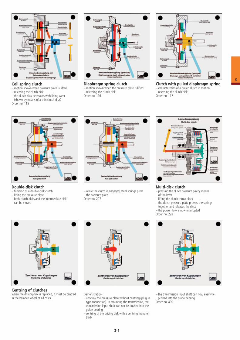
Coil spring clutch– motion shown when pressure plate is lifted– releasing the clutch disk– the clutch play decreases with lining wear
(shown by means of a thin clutch disk)Order no. 115
Diaphragm spring clutch– motion shown when the pressure plate is lifted– releasing the clutch diskOrder no. 116
Clutch with pulled diaphragm spring– characteristics of a pulled clutch in motion– releasing the clutch diskOrder no. 117
Double-disk clutch– function of a double-disk clutch– lifting the pressure plate– both clutch disks and the intermediate disk
can be moved
– while the clutch is engaged, steel springs press the pressure plate
Order no. 207
Multi-disk clutch– pressing the clutch pressure pin by means
of the lever– lifting the clutch thrust block– the clutch pressure-plate presses the springs
together and releases the discs– the power flow is now interruptedOrder no. 293
Centring of clutchesWhen the driving disk is replaced, it must be centred in the balance wheel at all costs.
Demonstration:– unscrew the pressure plate without centring (plug-in
type connection). In mounting the transmission, the transmission input shaft can not be pushed into the guide bearing
– centring of the driving disk with a centring mandrel (red)
– the transmission input shaft can now easily be pushed into the guide bearing
Order no. 490
3-1
3
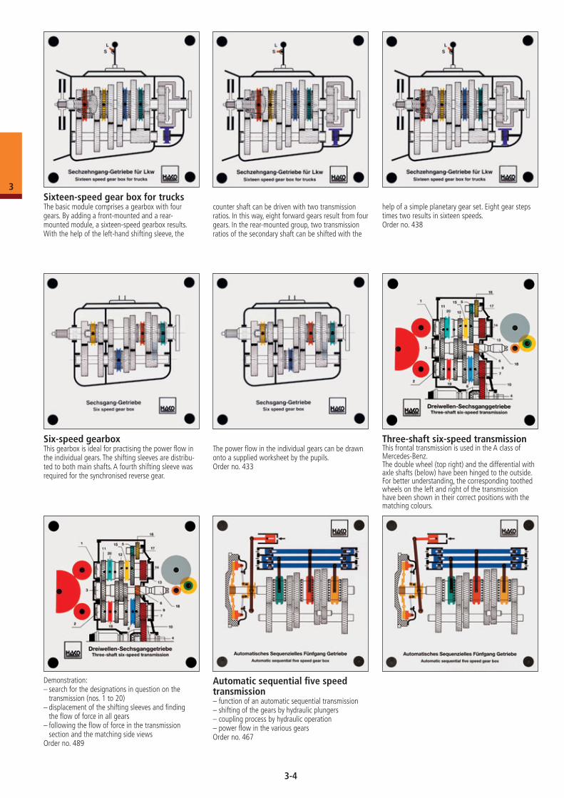
Dual-mass flywheel– design of a dual-mass flywheel– function of the pressure springs when primary
flyweight is subject to torsional vibrations
– function of the torsional-vibration damper between primary and secondary flyweight
Order no. 275
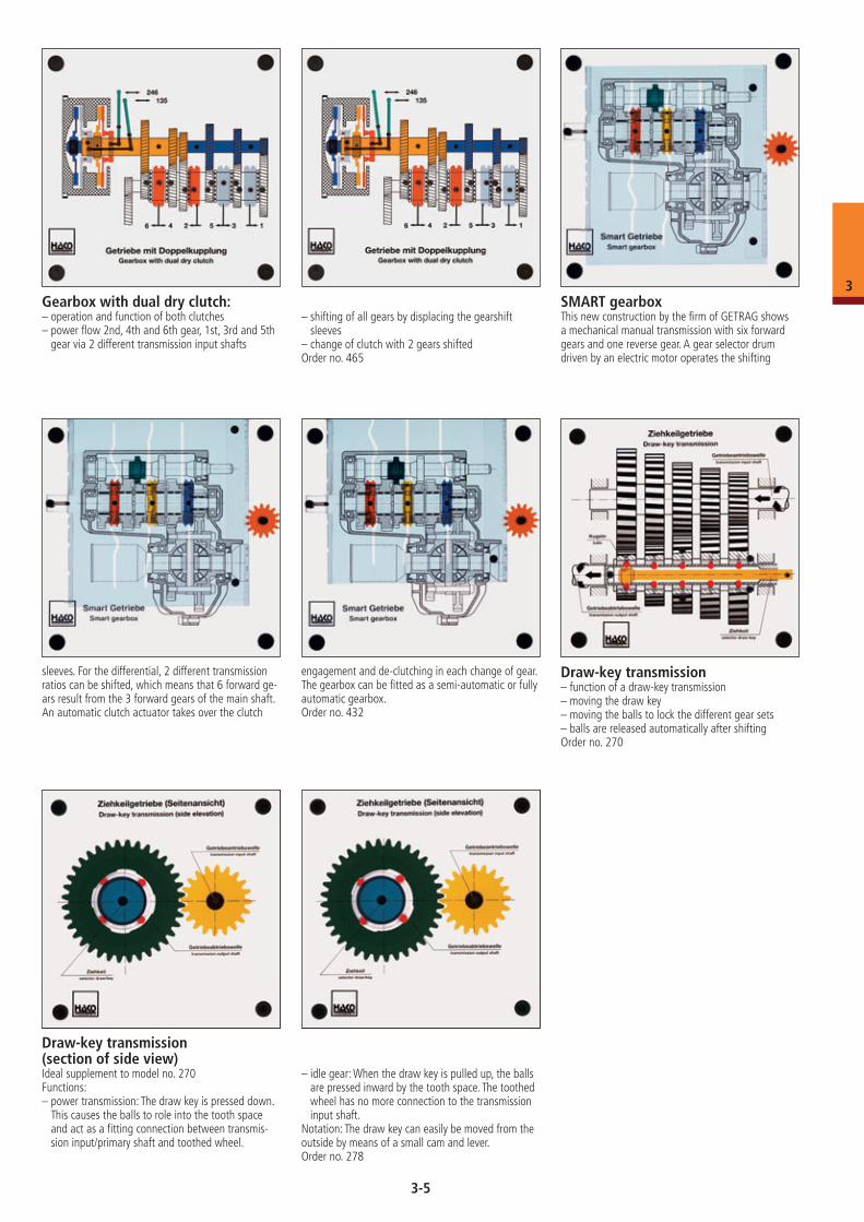
Planetary dual-mass flywheel– rotation of the secondary flywheel mass against
the primary flywheel– pressing the springs together in their guide shoes
without housing friction
– acceleration of the planetary wheels, which attenuate the vibrations of the springs thanks to their friction
Order no. 469
Clutch actuator– function of the solenoid valves– function of the diaphragm and of the
retractor spring– function of the position transducer– declutching process– clutch engagement processOrder no. 324
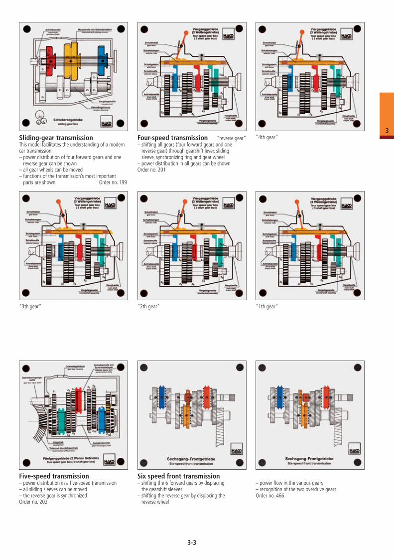
Centrifugal clutch– turning the driving crank sets the driving flange
into motion– centrifugal force presses the flyweights with the
friction lining against the clutch-drum, thereby driving the clutch-drum
Order no. 295
Hydraulically operated clutch– interaction of master cylinder and slave cylinder– actuating the clutch release fork– function of the compensation orifice and bleedingOrder no. 279
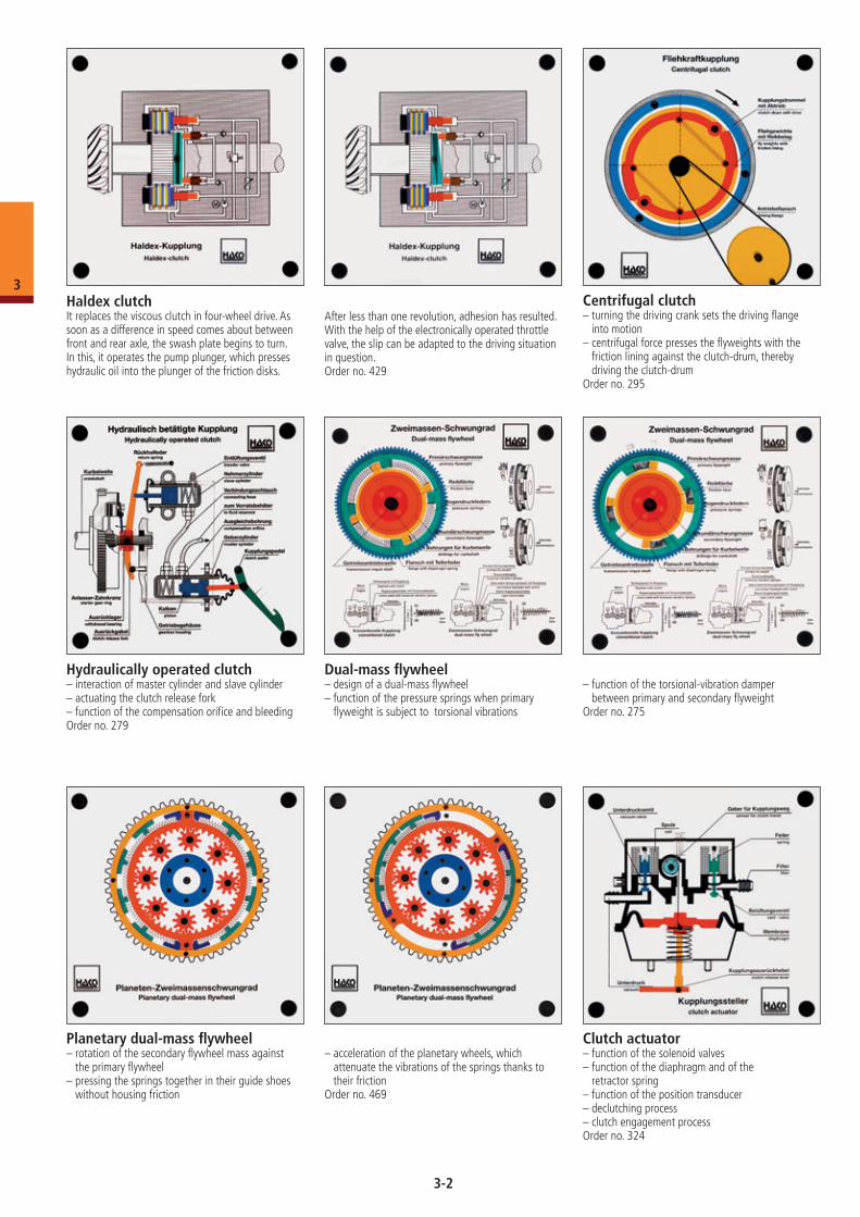
Haldex clutchIt replaces the viscous clutch in four-wheel drive. As soon as a difference in speed comes about between front and rear axle, the swash plate begins to turn. In this, it operates the pump plunger, which presses hydraulic oil into the plunger of the friction disks.
After less than one revolution, adhesion has resulted. With the help of the electronically operated throttle valve, the slip can be adapted to the driving situation in question.Order no. 429
3-2
3
Six speed front transmission– shifting the 6 forward gears by displacing
the gearshift sleeves– shifting the reverse gear by displacing the
reverse wheel
– power flow in the various gears– recognition of the two overdrive gearsOrder no. 466
Four-speed transmission “reverse gear“– shifting all gears (four forward gears and one
reverse gear) through gearshift lever, sliding sleeve, synchronizing ring and gear wheel
– power distribution in all gears can be shownOrder no. 201
“4th gear“
“3th gear“ “2th gear“ “1th gear“
Sliding-gear transmissionThis model facilitates the understanding of a modern car transmission:– power distribution of four forward gears and one
reverse gear can be shown– all gear wheels can be moved– functions of the transmission’s most important
parts are shown Order no. 199
Five-speed transmission– power distribution in a five-speed transmission– all sliding sleeves can be moved– the reverse gear is synchronizedOrder no. 202
3-3
3
Sixteen-speed gear box for trucksThe basic module comprises a gearbox with four gears. By adding a front-mounted and a rear- mounted module, a sixteen-speed gearbox results. With the help of the left-hand shifting sleeve, the
counter shaft can be driven with two transmission ratios. In this way, eight forward gears result from four gears. In the rear-mounted group, two transmission ratios of the secondary shaft can be shifted with the
help of a simple planetary gear set. Eight gear steps times two results in sixteen speeds.Order no. 438
Six-speed gearboxThis gearbox is ideal for practising the power flow in the individual gears. The shifting sleeves are distribu-ted to both main shafts. A fourth shifting sleeve was required for the synchronised reverse gear.
The power flow in the individual gears can be drawn onto a supplied worksheet by the pupils.Order no. 433
Three-shaft six-speed transmissionThis frontal transmission is used in the A class of Mercedes-Benz.The double wheel (top right) and the differential with axle shafts (below) have been hinged to the outside. For better understanding, the corresponding toothed wheels on the left and right of the transmission have been shown in their correct positions with the matching colours.
Demonstration:– search for the designations in question on the
transmission (nos. 1 to 20)– displacement of the shifting sleeves and finding
the flow of force in all gears– following the flow of force in the transmission
section and the matching side viewsOrder no. 489
Automatic sequential five speed transmission– function of an automatic sequential transmission– shifting of the gears by hydraulic plungers– coupling process by hydraulic operation– power flow in the various gearsOrder no. 467
3-4
3
Gearbox with dual dry clutch:– operation and function of both clutches– power flow 2nd, 4th and 6th gear, 1st, 3rd and 5th
gear via 2 different transmission input shafts
– shifting of all gears by displacing the gearshift sleeves
– change of clutch with 2 gears shiftedOrder no. 465
SMART gearboxThis new construction by the firm of GETRAG shows a mechanical manual transmission with six forward gears and one reverse gear. A gear selector drum driven by an electric motor operates the shifting
sleeves. For the differential, 2 different transmission ratios can be shifted, which means that 6 forward ge-ars result from the 3 forward gears of the main shaft. An automatic clutch actuator takes over the clutch
engagement and de-clutching in each change of gear. The gearbox can be fitted as a semi-automatic or fully automatic gearbox.Order no. 432
Draw-key transmission– function of a draw-key transmission– moving the draw key– moving the balls to lock the different gear sets– balls are released automatically after shiftingOrder no. 270
Draw-key transmission (section of side view)Ideal supplement to model no. 270Functions:– power transmission: The draw key is pressed down.
This causes the balls to role into the tooth space and act as a fitting connection between transmis-sion input/primary shaft and toothed wheel.
– idle gear: When the draw key is pulled up, the balls are pressed inward by the tooth space. The toothed wheel has no more connection to the transmission input shaft.
Notation: The draw key can easily be moved from the outside by means of a small cam and lever.Order no. 278
3-5
3
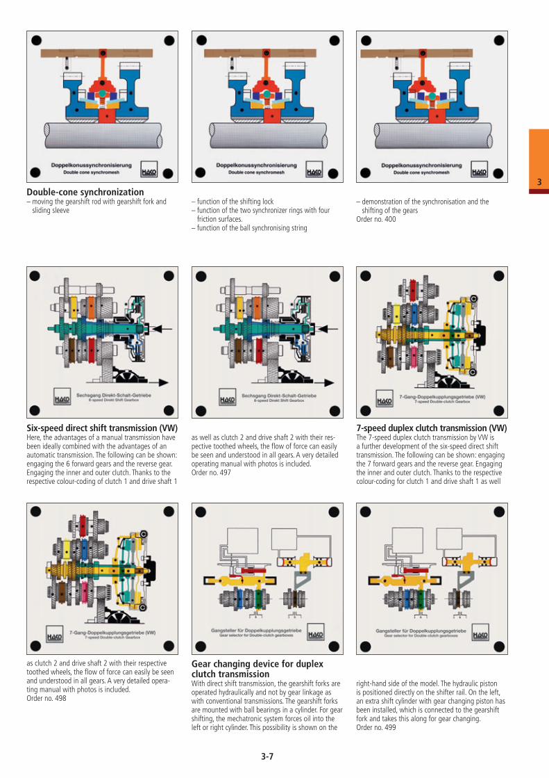
Transfer case– power distribution in a transfer case– shift options: front axle only, rear axle only and both
axles (four-wheel drive)Order no. 203
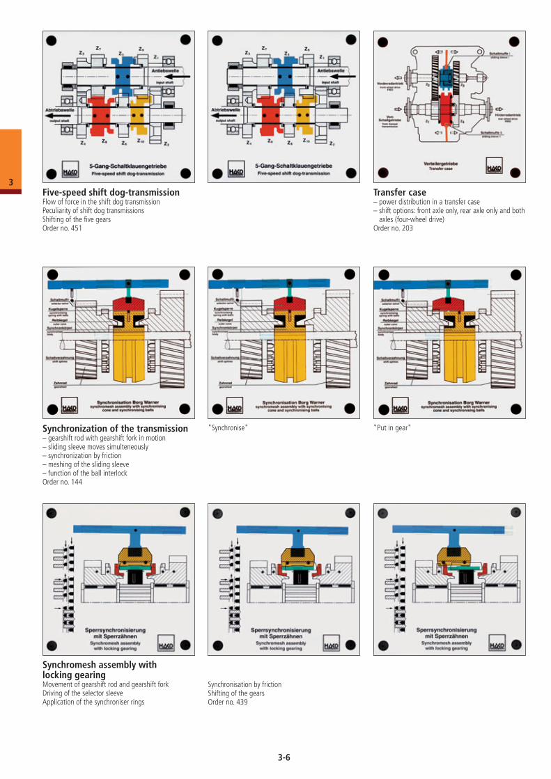
Five-speed shift dog-transmissionFlow of force in the shift dog transmissionPeculiarity of shift dog transmissionsShifting of the five gearsOrder no. 451
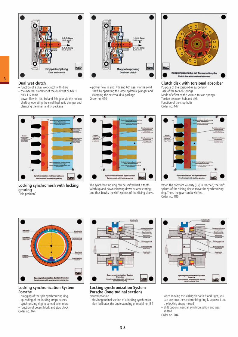
Synchronization of the transmission– gearshift rod with gearshift fork in motion– sliding sleeve moves simulteneously– synchronization by friction– meshing of the sliding sleeve– function of the ball interlockOrder no. 144
"Synchronise" "Put in gear"
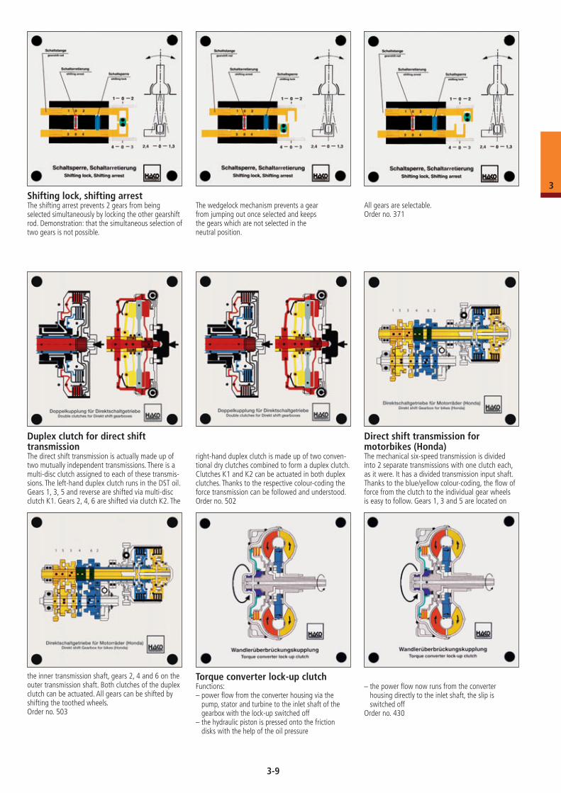
Synchromesh assembly with locking gearingMovement of gearshift rod and gearshift forkDriving of the selector sleeveApplication of the synchroniser rings
Synchronisation by frictionShifting of the gearsOrder no. 439
3-6
3
Double-cone synchronization– moving the gearshift rod with gearshift fork and
sliding sleeve– function of the shifting lock– function of the two synchronizer rings with four
friction surfaces.– function of the ball synchronising string
– demonstration of the synchronisation and the shifting of the gears
Order no. 400
as clutch 2 and drive shaft 2 with their respective toothed wheels, the flow of force can easily be seen and understood in all gears. A very detailed opera-ting manual with photos is included. Order no. 498
Gear changing device for duplex clutch transmissionWith direct shift transmission, the gearshift forks are operated hydraulically and not by gear linkage as with conventional transmissions. The gearshift forks are mounted with ball bearings in a cylinder. For gear shifting, the mechatronic system forces oil into the left or right cylinder. This possibility is shown on the
right-hand side of the model. The hydraulic piston is positioned directly on the shifter rail. On the left, an extra shift cylinder with gear changing piston has been installed, which is connected to the gearshift fork and takes this along for gear changing.Order no. 499
7-speed duplex clutch transmission (VW)The 7-speed duplex clutch transmission by VW is a further development of the six-speed direct shift transmission. The following can be shown: engaging the 7 forward gears and the reverse gear. Engaging the inner and outer clutch. Thanks to the respective colour-coding for clutch 1 and drive shaft 1 as well
as well as clutch 2 and drive shaft 2 with their res-pective toothed wheels, the flow of force can easily be seen and understood in all gears. A very detailed operating manual with photos is included.Order no. 497
Six-speed direct shift transmission (VW)Here, the advantages of a manual transmission have been ideally combined with the advantages of an automatic transmission. The following can be shown: engaging the 6 forward gears and the reverse gear. Engaging the inner and outer clutch. Thanks to the respective colour-coding of clutch 1 and drive shaft 1
3-7
3
Dual wet clutch– function of a dual wet clutch with disks– the external diameter of the dual wet clutch is
only 117 mm!– power flow in 1st, 3rd and 5th gear via the hollow
shaft by operating the small hydraulic plunger and clamping the internal disk package
– power flow in 2nd, 4th and 6th gear via the solid shaft by operating the large hydraulic plunger and clamping the external disk package
Order no. 470
Clutch disk with torsional absorberPurpose of the torsion-bar suspensionTask of the torsion springsMode of effect of the various torsion springsTorsion between hub and diskFunction of the stop boltsOrder no. 447
Locking synchronization System Porsche– dragging of the split synchronizing ring– spreading of the locking straps causes
synchronizing ring to spread even more– function of detent block and stop blockOrder no. 164
Locking synchronization System Porsche (longitudinal section)Neutral position– this longitudinal section of a locking synchroniza-
tion facilitates the understanding of model no.164
– when moving the sliding sleeve left and right, you can see how the synchronizing ring is squeezed and the locking straps moved
– shift options: neutral, synchronization and gear shifted
Order no. 204
Locking synchromesh with locking gearing"idle position"
The synchronizing ring can be shifted half a tooth width up and down (slowing down or accelerating) and thus blocks the shift splines of the sliding sleeve.
When the constant velocity (CV) is reached, the shift splines of the sliding sleeve move the synchronizing ring. Then, the gear can be shifted.Order no. 186
3-8
3
Shifting lock, shifting arrestThe shifting arrest prevents 2 gears from being selected simultaneously by locking the other gearshift rod. Demonstration: that the simultaneous selection of two gears is not possible.
The wedgelock mechanism prevents a gear from jumping out once selected and keepsthe gears which are not selected in the neutral position.
All gears are selectable.Order no. 371
Duplex clutch for direct shift transmissionThe direct shift transmission is actually made up of two mutually independent transmissions. There is a multi-disc clutch assigned to each of these transmis-sions. The left-hand duplex clutch runs in the DST oil. Gears 1, 3, 5 and reverse are shifted via multi-disc clutch K1. Gears 2, 4, 6 are shifted via clutch K2. The
right-hand duplex clutch is made up of two conven-tional dry clutches combined to form a duplex clutch. Clutches K1 and K2 can be actuated in both duplex clutches. Thanks to the respective colour-coding the force transmission can be followed and understood.Order no. 502
Direct shift transmission for motorbikes (Honda)The mechanical six-speed transmission is divided into 2 separate transmissions with one clutch each, as it were. It has a divided transmission input shaft. Thanks to the blue/yellow colour-coding, the flow of force from the clutch to the individual gear wheels is easy to follow. Gears 1, 3 and 5 are located on
the inner transmission shaft, gears 2, 4 and 6 on the outer transmission shaft. Both clutches of the duplex clutch can be actuated. All gears can be shifted by shifting the toothed wheels.Order no. 503
Torque converter lock-up clutchFunctions:– power flow from the converter housing via the
pump, stator and turbine to the inlet shaft of the gearbox with the lock-up switched off
– the hydraulic piston is pressed onto the friction disks with the help of the oil pressure
– the power flow now runs from the converter housing directly to the inlet shaft, the slip is switched off
Order no. 430
3-9
3
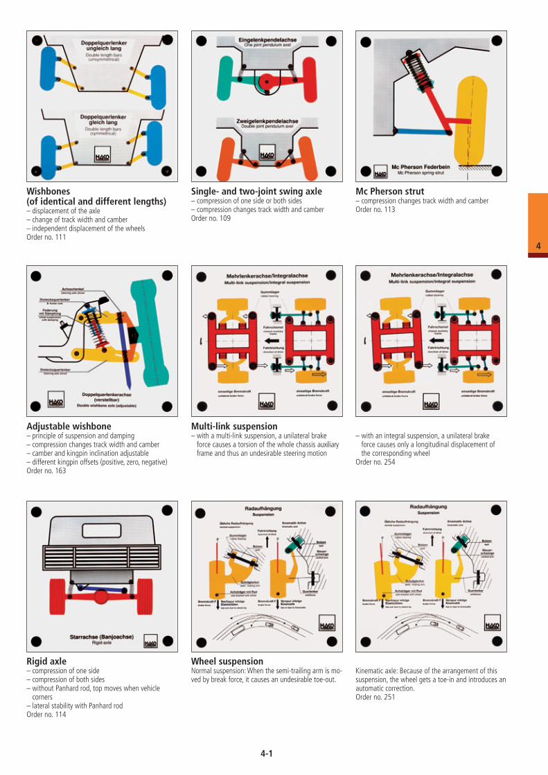
Planetary axle wheel drive assembly– function of a wheel drive assembly– ratio in the planetary gear
– when you turn the axle shaft, you see how the wheel turns with a ratio of 1: 4
Order no. 473
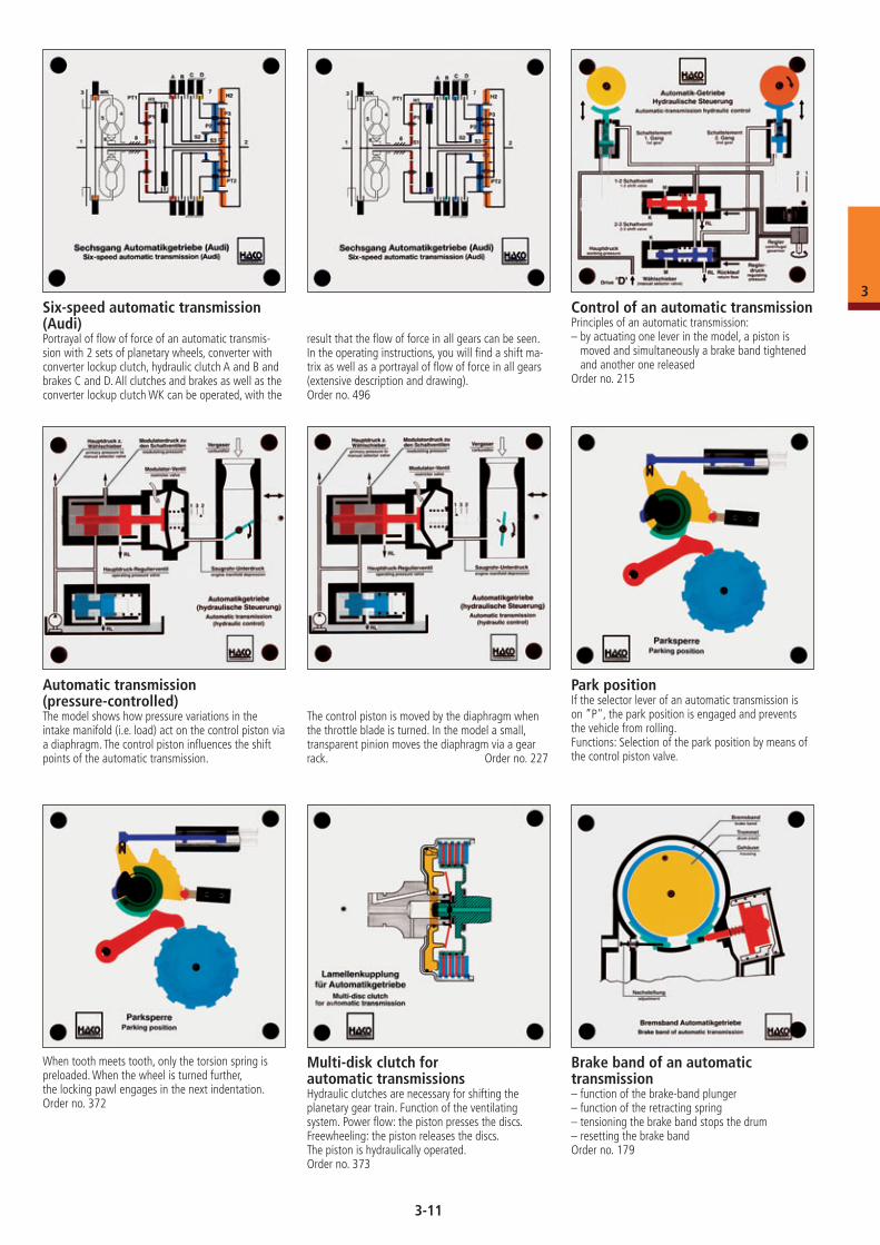
Simple planetary gear train All transmission ratios of a simple planetary gear train can be shown by driving and locking different parts of the model from the outside.Order no. 239
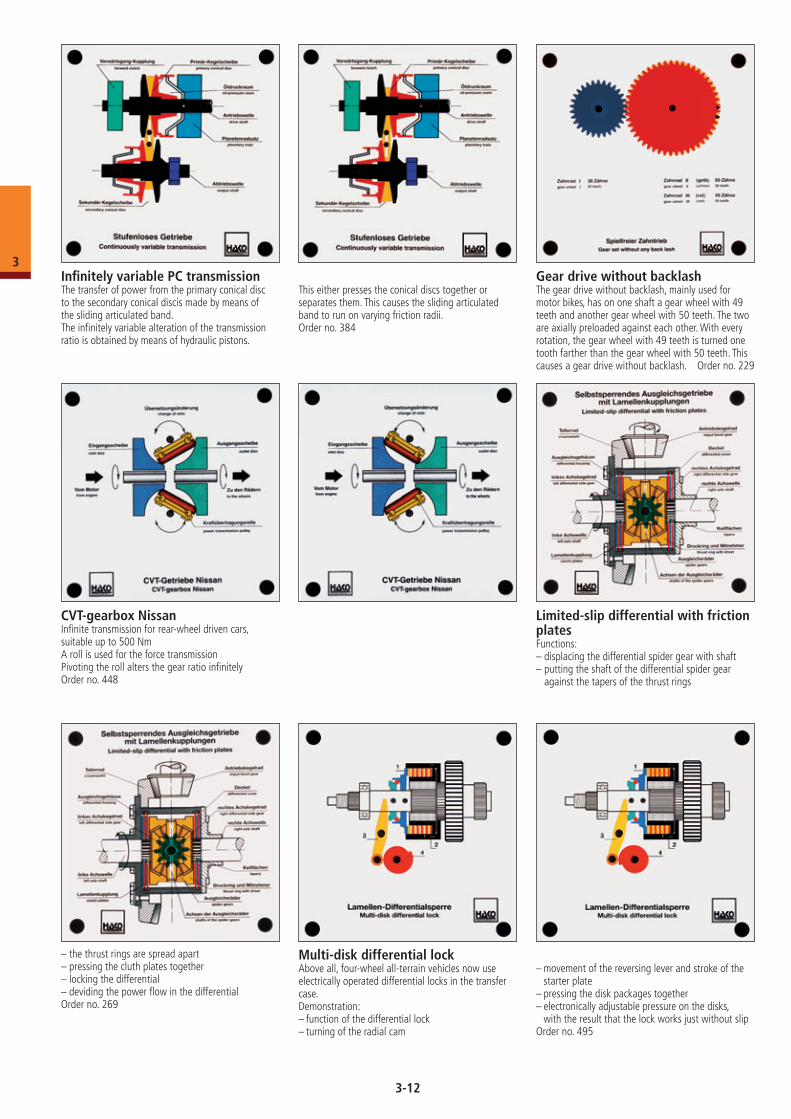
Planetary gear train: Ravigneaux gear setConsists of ring gear, planet carriers, two sun wheels and six planetary wheels.The gear train can be set to the desired transmission ratio from the outside.Order no. 240
Planetary gear train: Simpson gear setTwo simple planetary gear sets are combined to formed a single set. The Simpson gear set has 2 ring gears, 2 planet carriers and two connected sun wheels. Various gears (forwards and reverse) can be selected.Order no. 385
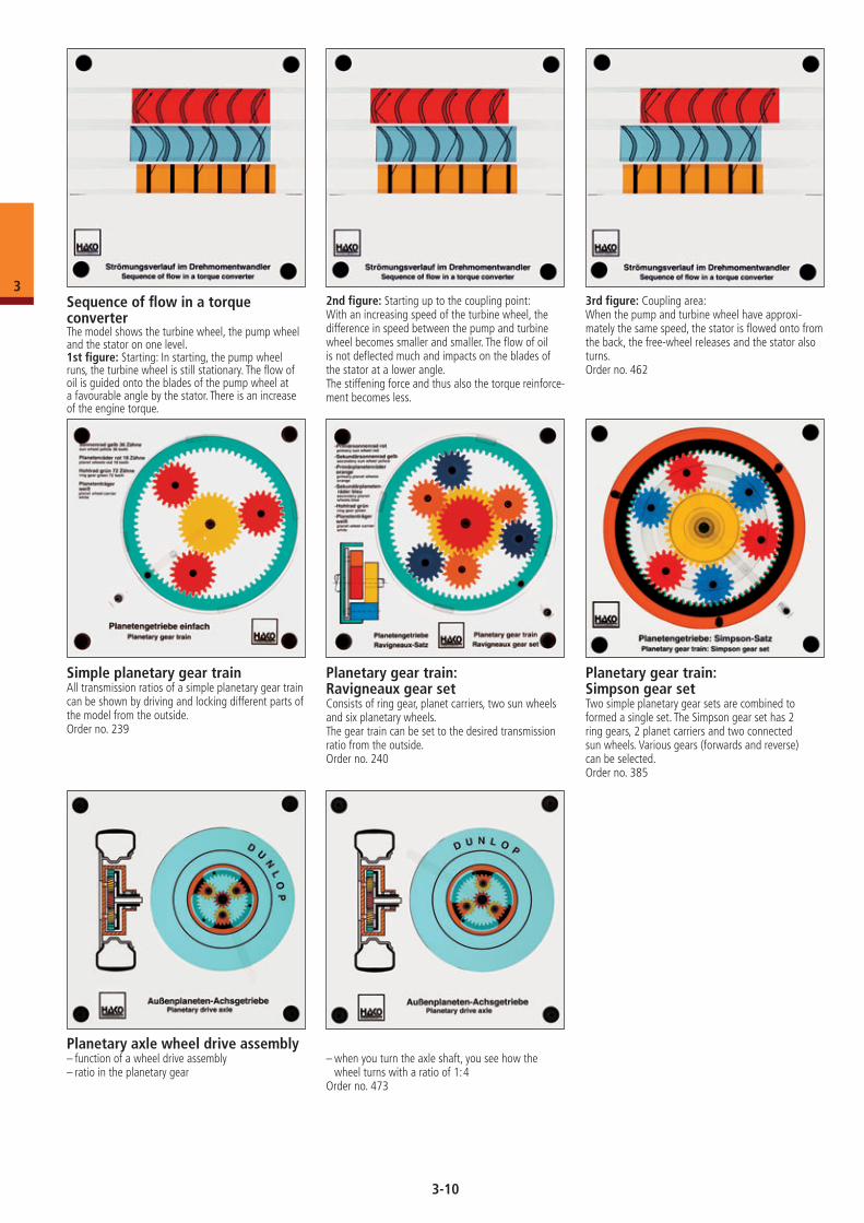
Sequence of flow in a torque converterThe model shows the turbine wheel, the pump wheel and the stator on one level.1st figure: Starting: In starting, the pump wheel runs, the turbine wheel is still stationary. The flow of oil is guided onto the blades of the pump wheel at a favourable angle by the stator. There is an increase of the engine torque.
2nd figure: Starting up to the coupling point:With an increasing speed of the turbine wheel, the difference in speed between the pump and turbine wheel becomes smaller and smaller. The flow of oil is not deflected much and impacts on the blades of the stator at a lower angle.The stiffening force and thus also the torque reinforce-ment becomes less.
3rd figure: Coupling area:When the pump and turbine wheel have approxi-mately the same speed, the stator is flowed onto from the back, the free-wheel releases and the stator also turns.Order no. 462
3-10
3
Six-speed automatic transmission (Audi)Portrayal of flow of force of an automatic transmis-sion with 2 sets of planetary wheels, converter with converter lockup clutch, hydraulic clutch A and B and brakes C and D. All clutches and brakes as well as the converter lockup clutch WK can be operated, with the
result that the flow of force in all gears can be seen. In the operating instructions, you will find a shift ma-trix as well as a portrayal of flow of force in all gears (extensive description and drawing).Order no. 496
Control of an automatic transmissionPrinciples of an automatic transmission:– by actuating one lever in the model, a piston is
moved and simultaneously a brake band tightened and another one released
Order no. 215
Automatic transmission (pressure-controlled)The model shows how pressure variations in the intake manifold (i.e. load) act on the control piston via a diaphragm. The control piston influences the shift points of the automatic transmission.
The control piston is moved by the diaphragm when the throttle blade is turned. In the model a small, transparent pinion moves the diaphragm via a gear rack. Order no. 227
Park positionIf the selector lever of an automatic transmission is on ”P", the park position is engaged and prevents the vehicle from rolling.Functions: Selection of the park position by means of the control piston valve.
When tooth meets tooth, only the torsion spring is preloaded. When the wheel is turned further, the locking pawl engages in the next indentation.Order no. 372
Multi-disk clutch for automatic transmissionsHydraulic clutches are necessary for shifting the planetary gear train. Function of the ventilating system. Power flow: the piston presses the discs. Freewheeling: the piston releases the discs.The piston is hydraulically operated.Order no. 373
Brake band of an automatic transmission– function of the brake-band plunger– function of the retracting spring– tensioning the brake band stops the drum– resetting the brake bandOrder no. 179
3-11
3
Gear drive without backlashThe gear drive without backlash, mainly used for motor bikes, has on one shaft a gear wheel with 49 teeth and another gear wheel with 50 teeth. The two are axially preloaded against each other. With every rotation, the gear wheel with 49 teeth is turned one tooth farther than the gear wheel with 50 teeth. This causes a gear drive without backlash. Order no. 229
Infinitely variable PC transmissionThe transfer of power from the primary conical disc to the secondary conical discis made by means of the sliding articulated band.The infinitely variable alteration of the transmission ratio is obtained by means of hydraulic pistons.
This either presses the conical discs together or separates them. This causes the sliding articulated band to run on varying friction radii.Order no. 384
Limited-slip differential with friction platesFunctions:– displacing the differential spider gear with shaft– putting the shaft of the differential spider gear
against the tapers of the thrust rings
– the thrust rings are spread apart– pressing the cluth plates together– locking the differential– deviding the power flow in the differentialOrder no. 269
CVT-gearbox NissanInfinite transmission for rear-wheel driven cars, suitable up to 500 NmA roll is used for the force transmissionPivoting the roll alters the gear ratio infinitelyOrder no. 448
Multi-disk differential lockAbove all, four-wheel all-terrain vehicles now use electrically operated differential locks in the transfer case. Demonstration:– function of the differential lock– turning of the radial cam
– movement of the reversing lever and stroke of the starter plate
– pressing the disk packages together– electronically adjustable pressure on the disks,
with the result that the lock works just without slipOrder no. 495
3-12
3
Wishbones (of identical and different lengths)– displacement of the axle– change of track width and camber– independent displacement of the wheelsOrder no. 111
Single- and two-joint swing axle– compression of one side or both sides– compression changes track width and camberOrder no. 109
Mc Pherson strut– compression changes track width and camberOrder no. 113
Adjustable wishbone– principle of suspension and damping– compression changes track width and camber– camber and kingpin inclination adjustable– different kingpin offsets (positive, zero, negative)Order no. 163
Multi-link suspension– with a multi-link suspension, a unilateral brake
force causes a torsion of the whole chassis auxiliary frame and thus an undesirable steering motion
– with an integral suspension, a unilateral brake force causes only a longitudinal displacement of the corresponding wheel
Order no. 254
Rigid axle– compression of one side– compression of both sides– without Panhard rod, top moves when vehicle
corners– lateral stability with Panhard rodOrder no. 114
Wheel suspensionNormal suspension: When the semi-trailing arm is mo-ved by break force, it causes an undesirable toe-out.
Kinematic axle: Because of the arrangement of this suspension, the wheel gets a toe-in and introduces an automatic correction.Order no. 251
4-1
4
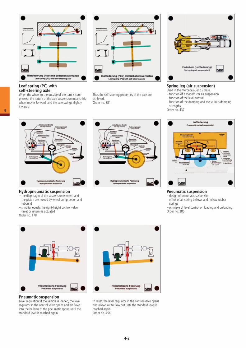
Leaf spring (PC) with self-steering axleWhen the wheel to the outside of the turn is com-pressed, the nature of the axle suspension means this wheel moves forward, and the axle swings slightly inwards.
Thus the self-steering properties of the axle are achieved.Order no. 381
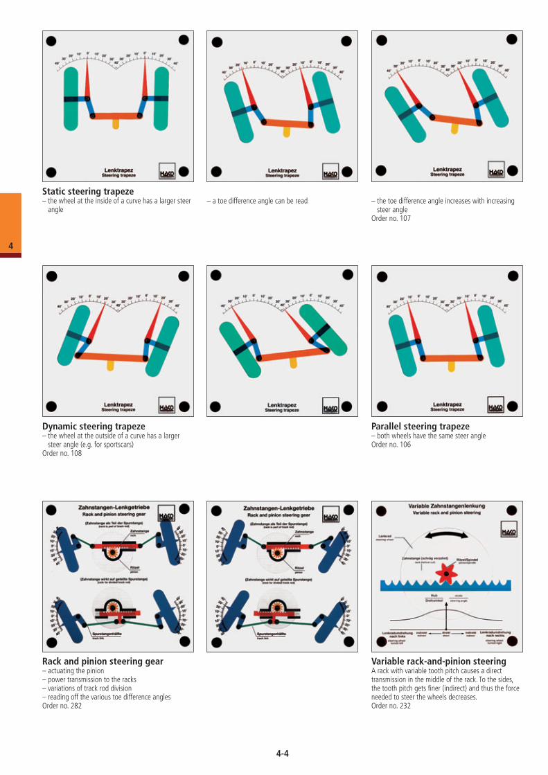
Hydropneumatic suspension– the diaphragm of the suspension element and
the piston are moved by wheel compression and rebound
– simultaneously, the right-height control valve (inlet or return) is actuated
Order no. 178
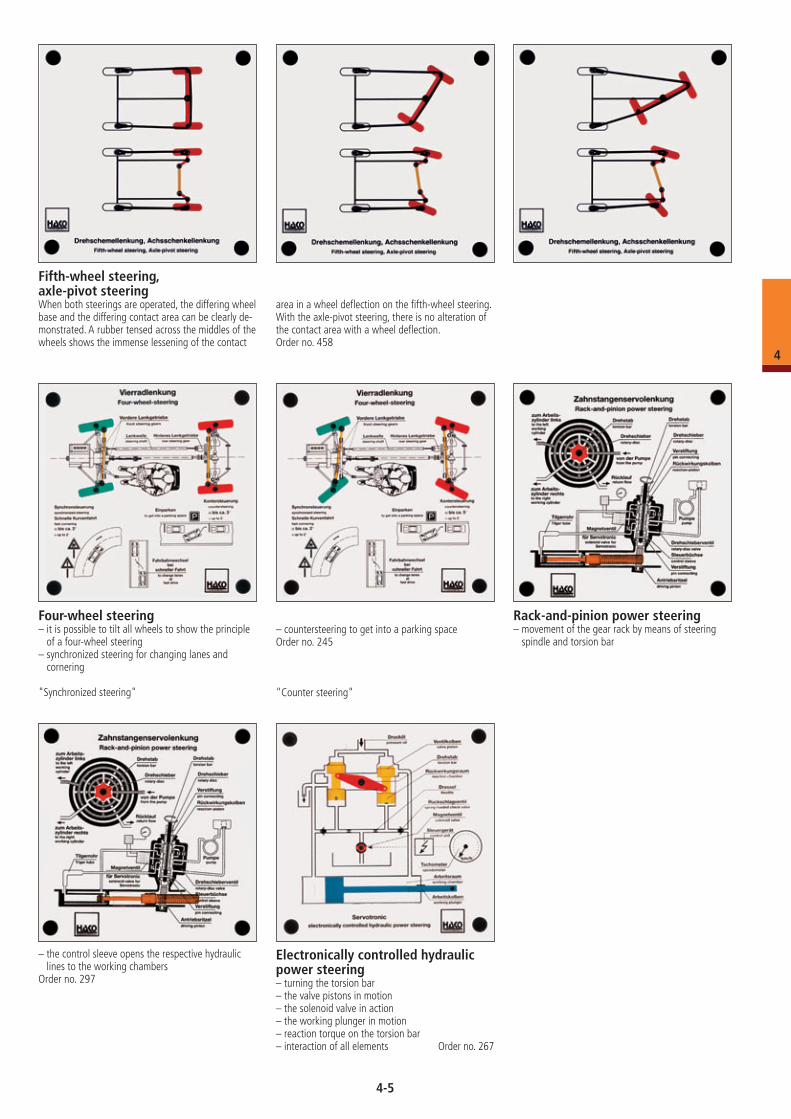
Pneumatic suspension– design of pneumatic suspension– effect of air spring bellows and hollow rubber
springs– principle of level control on loading and unloadingOrder no. 285
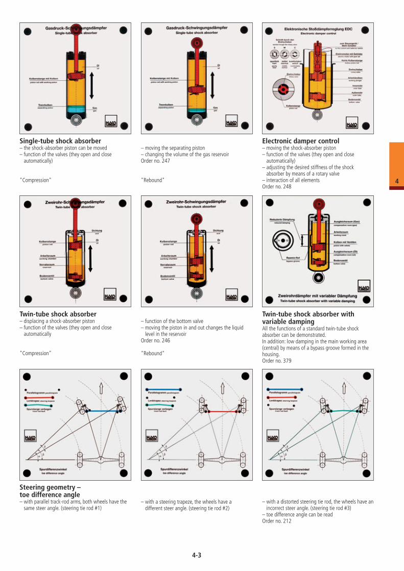
Spring leg (air suspension)Used in the Mercedes-Benz S class.– function of a modern car air suspension– function of the level control– function of the damping and the various damping
strengthsOrder no. 437
Pneumatic suspensionLevel regulation: if the vehicle is loaded, the level regulator in the control valve opens and air flows into the bellows of the pneumatic spring until the standard level is reached again.
In relief, the level regulator in the control valve opens and allows air to flow out until the standard level is reached again.Order no. 456
4-2
4
Single-tube shock absorber– the shock-absorber piston can be moved– function of the valves (they open and close
automatically)
"Compression"
– moving the separating piston– changing the volume of the gas reservoirOrder no. 247
"Rebound"
Electronic damper control– moving the shock-absorber piston– function of the valves (they open and close
automatically)– adjusting the desired stiffness of the shock
absorber by means of a rotary valve– interaction of all elementsOrder no. 248
Steering geometry – toe difference angle– with parallel track-rod arms, both wheels have the
same steer angle. (steering tie rod #1)– with a steering trapeze, the wheels have a
different steer angle. (steering tie rod #2)– with a distorted steering tie rod, the wheels have an
incorrect steer angle. (steering tie rod #3)– toe difference angle can be readOrder no. 212
Twin-tube shock absorber with variable dampingAll the functions of a standard twin-tube shock absorber can be demonstrated.In addition: low damping in the main working area (central) by means of a bypass groove formed in the housing.Order no. 379
Twin-tube shock absorber– displacing a shock-absorber piston– function of the valves (they open and close
automatically
"Compression"
– function of the bottom valve– moving the piston in and out changes the liquid
level in the reservoirOrder no. 246
"Rebound"
4-3
4
Static steering trapeze– the wheel at the inside of a curve has a larger steer
angle– a toe difference angle can be read – the toe difference angle increases with increasing
steer angleOrder no. 107
Dynamic steering trapeze– the wheel at the outside of a curve has a larger
steer angle (e.g. for sportscars)Order no. 108
Parallel steering trapeze– both wheels have the same steer angleOrder no. 106
Rack and pinion steering gear– actuating the pinion– power transmission to the racks– variations of track rod division– reading off the various toe difference anglesOrder no. 282
Variable rack-and-pinion steering A rack with variable tooth pitch causes a direct transmission in the middle of the rack. To the sides, the tooth pitch gets finer (indirect) and thus the force needed to steer the wheels decreases. Order no. 232
4-4
4
Four-wheel steering– it is possible to tilt all wheels to show the principle
of a four-wheel steering– synchronized steering for changing lanes and
cornering
"Synchronized steering"
– countersteering to get into a parking spaceOrder no. 245
"Counter steering"
Fifth-wheel steering, axle-pivot steeringWhen both steerings are operated, the differing wheel base and the differing contact area can be clearly de-monstrated. A rubber tensed across the middles of the wheels shows the immense lessening of the contact
area in a wheel deflection on the fifth-wheel steering. With the axle-pivot steering, there is no alteration of the contact area with a wheel deflection.Order no. 458
Rack-and-pinion power steering – movement of the gear rack by means of steering
spindle and torsion bar
– the control sleeve opens the respective hydraulic lines to the working chambers
Order no. 297
Electronically controlled hydraulic power steering– turning the torsion bar– the valve pistons in motion– the solenoid valve in action– the working plunger in motion– reaction torque on the torsion bar– interaction of all elements Order no. 267
4-5
4
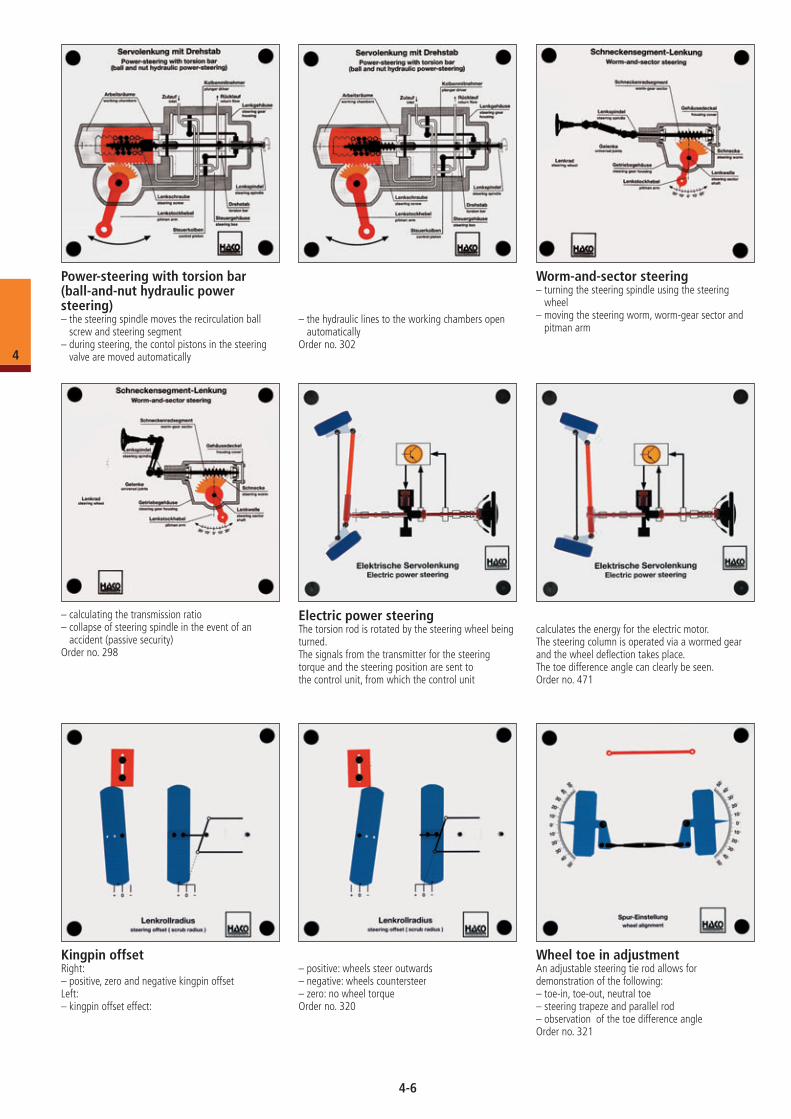
Electric power steeringThe torsion rod is rotated by the steering wheel being turned.The signals from the transmitter for the steering torque and the steering position are sent to the control unit, from which the control unit
calculates the energy for the electric motor.The steering column is operated via a wormed gear and the wheel deflection takes place. The toe difference angle can clearly be seen.Order no. 471
Worm-and-sector steering– turning the steering spindle using the steering
wheel– moving the steering worm, worm-gear sector and
pitman arm
– calculating the transmission ratio– collapse of steering spindle in the event of an
accident (passive security)Order no. 298
Power-steering with torsion bar (ball-and-nut hydraulic power steering)– the steering spindle moves the recirculation ball
screw and steering segment– during steering, the contol pistons in the steering
valve are moved automatically
– the hydraulic lines to the working chambers open automatically
Order no. 302
Kingpin offsetRight:– positive, zero and negative kingpin offsetLeft:– kingpin offset effect:
– positive: wheels steer outwards– negative: wheels countersteer– zero: no wheel torqueOrder no. 320
Wheel toe in adjustmentAn adjustable steering tie rod allows fordemonstration of the following:– toe-in, toe-out, neutral toe– steering trapeze and parallel rod– observation of the toe difference angleOrder no. 321
4-6
4
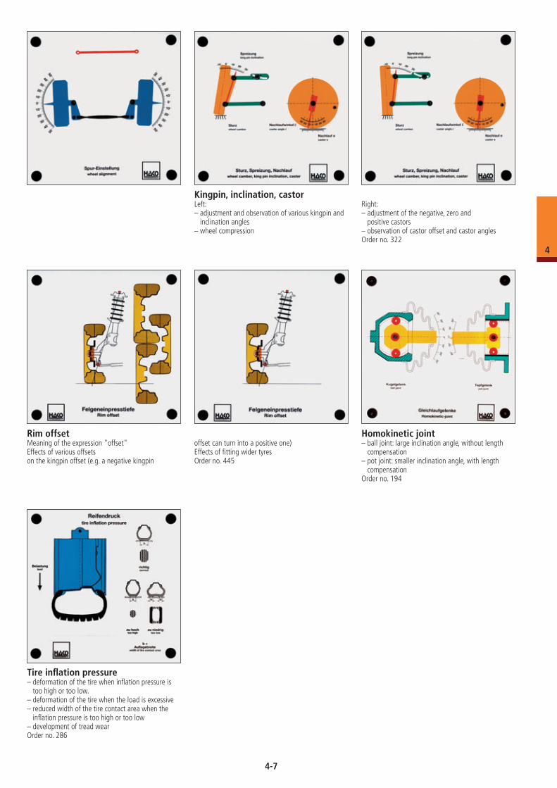
Kingpin, inclination, castorLeft:– adjustment and observation of various kingpin and
inclination angles– wheel compression
Right:– adjustment of the negative, zero and
positive castors– observation of castor offset and castor anglesOrder no. 322
Rim offsetMeaning of the expression "offset"Effects of various offsetson the kingpin offset (e.g. a negative kingpin
offset can turn into a positive one)Effects of fitting wider tyresOrder no. 445
Homokinetic joint– ball joint: large inclination angle, without length
compensation– pot joint: smaller inclination angle, with length
compensationOrder no. 194
Tire inflation pressure– deformation of the tire when inflation pressure is
too high or too low.– deformation of the tire when the load is excessive– reduced width of the tire contact area when the
inflation pressure is too high or too low– development of tread wearOrder no. 286
4-7
4
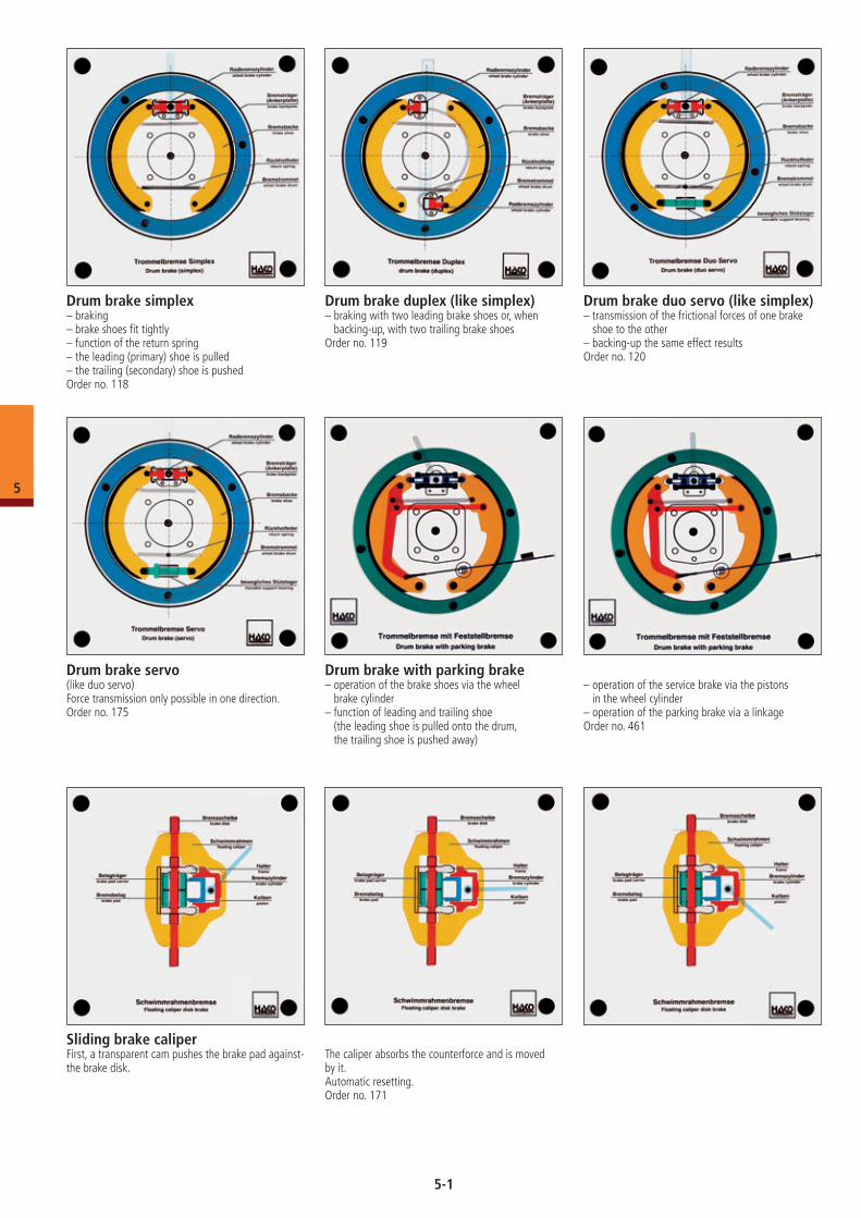
Drum brake with parking brake– operation of the brake shoes via the wheel
brake cylinder– function of leading and trailing shoe
(the leading shoe is pulled onto the drum, the trailing shoe is pushed away)
– operation of the service brake via the pistons in the wheel cylinder
– operation of the parking brake via a linkageOrder no. 461
Drum brake simplex– braking– brake shoes fit tightly– function of the return spring– the leading (primary) shoe is pulled– the trailing (secondary) shoe is pushedOrder no. 118
Drum brake duplex (like simplex)– braking with two leading brake shoes or, when
backing-up, with two trailing brake shoesOrder no. 119
Drum brake duo servo (like simplex)– transmission of the frictional forces of one brake
shoe to the other– backing-up the same effect resultsOrder no. 120
Drum brake servo (like duo servo)Force transmission only possible in one direction.Order no. 175
Sliding brake caliperFirst, a transparent cam pushes the brake pad against-the brake disk.
The caliper absorbs the counterforce and is moved by it.Automatic resetting.Order no. 171
5
5-1
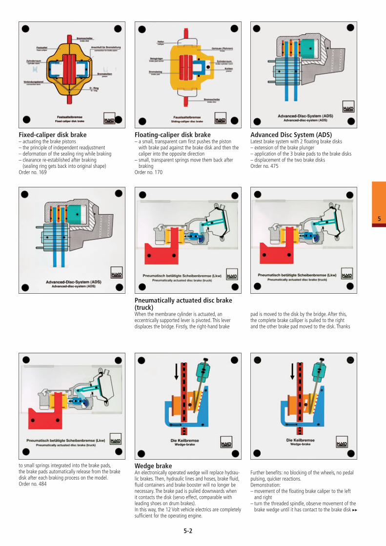
Fixed-caliper disk brake– actuating the brake pistons– the principle of independent readjustment– deformation of the sealing ring while braking– clearance re-established after braking
(sealing ring gets back into original shape)Order no. 169
Floating-caliper disk brake– a small, transparent cam first pushes the piston
with brake pad against the brake disk and then the caliper into the opposite direction
– small, transparent springs move them back after braking
Order no. 170
Advanced Disc System (ADS)Latest brake system with 2 floating brake disks– extension of the brake plunger– application of the 3 brake pads to the brake disks– displacement of the two brake disksOrder no. 475
Pneumatically actuated disc brake (truck)When the membrane cylinder is actuated, an eccentrically supported lever is pivoted. This lever displaces the bridge. Firstly, the right-hand brake
pad is moved to the disk by the bridge. After this, the complete brake calliper is pulled to the right and the other brake pad moved to the disk. Thanks
to small springs integrated into the brake pads, the brake pads automatically release from the brake disk after each braking process on the model.Order no. 484
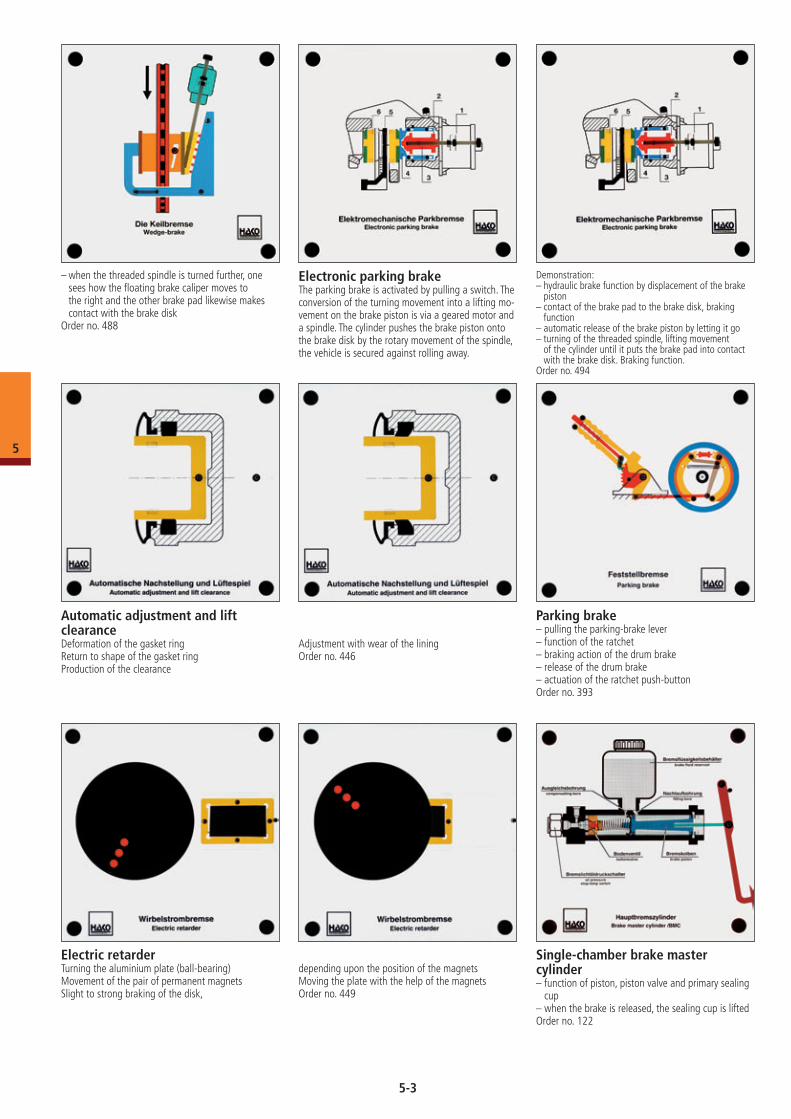
Wedge brakeAn electronically operated wedge will replace hydrau-lic brakes. Then, hydraulic lines and hoses, brake fluid, fluid containers and brake booster will no longer be necessary. The brake pad is pulled downwards when it contacts the disk (servo effect, comparable with leading shoes on drum brakes).In this way, the 12 Volt vehicle electrics are completely sufficient for the operating engine.
Further benefits: no blocking of the wheels, no pedal pulsing, quicker reactions.Demonstration:– movement of the floating brake caliper to the left
and right– turn the threaded spindle, observe movement of the
brake wedge until it has contact to the brake disk
5
5-2
Automatic adjustment and lift clearanceDeformation of the gasket ringReturn to shape of the gasket ringProduction of the clearance
Adjustment with wear of the liningOrder no. 446
Electric retarderTurning the aluminium plate (ball-bearing)Movement of the pair of permanent magnetsSlight to strong braking of the disk,
depending upon the position of the magnetsMoving the plate with the help of the magnetsOrder no. 449
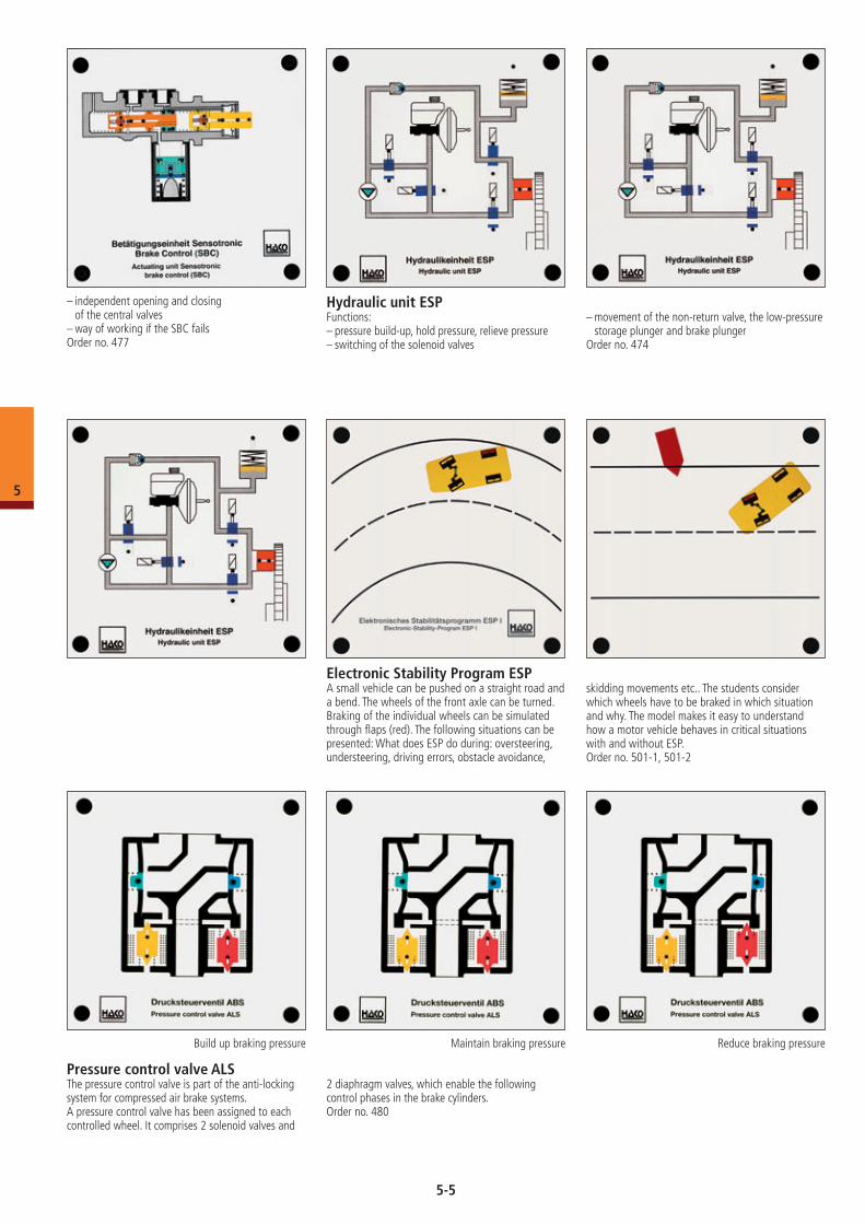
Parking brake– pulling the parking-brake lever– function of the ratchet– braking action of the drum brake– release of the drum brake– actuation of the ratchet push-button Order no. 393
– when the threaded spindle is turned further, one sees how the floating brake caliper moves to the right and the other brake pad likewise makes contact with the brake disk
Order no. 488
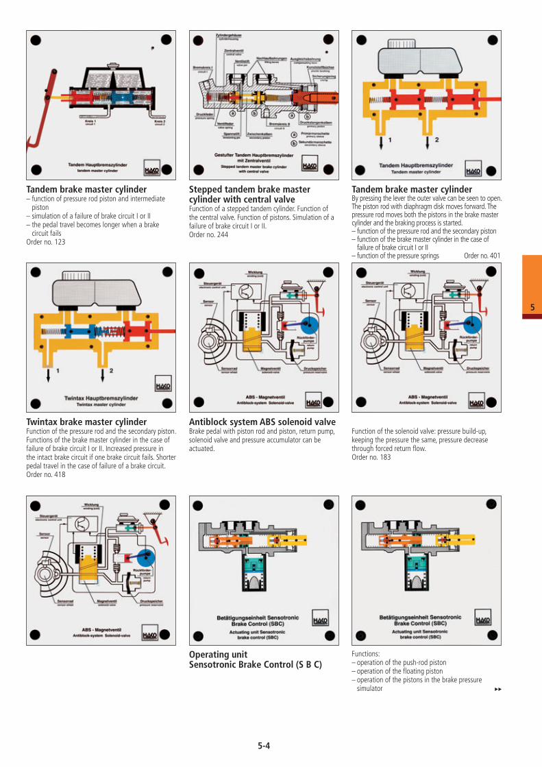
Electronic parking brakeThe parking brake is activated by pulling a switch. The conversion of the turning movement into a lifting mo-vement on the brake piston is via a geared motor and a spindle. The cylinder pushes the brake piston onto the brake disk by the rotary movement of the spindle, the vehicle is secured against rolling away.
Demonstration:– hydraulic brake function by displacement of the brake
piston– contact of the brake pad to the brake disk, braking
function– automatic release of the brake piston by letting it go– turning of the threaded spindle, lifting movement
of the cylinder until it puts the brake pad into contact with the brake disk. Braking function.
Order no. 494
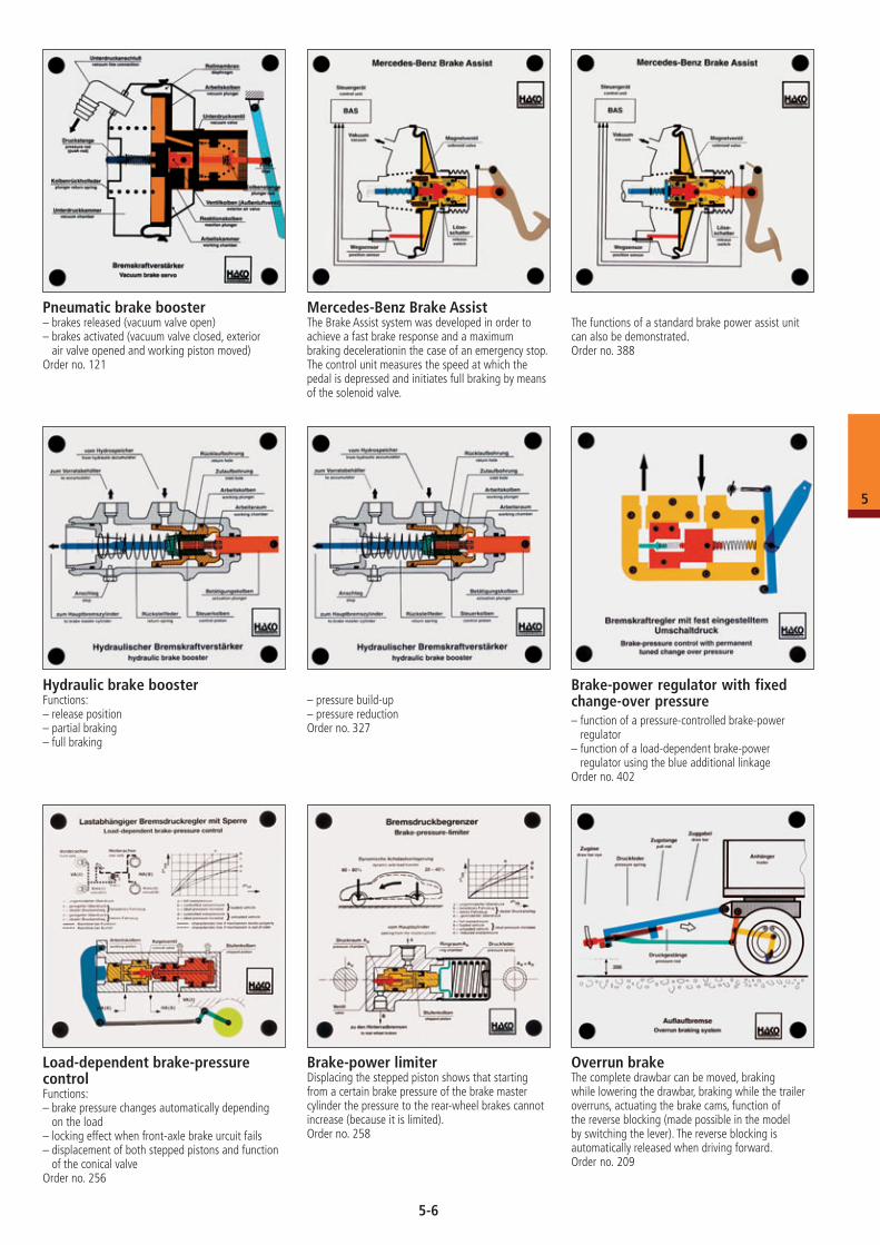
Single-cham ber brake master cylinder– function of piston, piston valve and primary sealing
cup– when the brake is released, the sealing cup is liftedOrder no. 122
5
5-3
Tandem brake master cylinder– function of pressure rod piston and intermediate
piston– simulation of a failure of brake circuit I or II– the pedal travel becomes longer when a brake
circuit failsOrder no. 123
Stepped tandem brake master cylinder with central valveFunction of a stepped tandem cylinder. Function of the central valve. Function of pistons. Simulation of a failure of brake circuit I or II.Order no. 244
Tandem brake master cylinderBy pressing the lever the outer valve can be seen to open. The piston rod with diaphragm disk moves forward. The pressure rod moves both the pistons in the brake master cylinder and the braking process is started. – function of the pressure rod and the secondary piston– function of the brake master cylinder in the case of
failure of brake circuit I or II– function of the pressure springs Order no. 401
Twintax brake master cylinderFunction of the pressure rod and the secondary piston. Functions of the brake master cylinder in the case of failure of brake circuit I or II. Increased pressure in the intact brake circuit if one brake circuit fails. Shorter pedal travel in the case of failure of a brake circuit.Order no. 418
Antiblock system ABS solenoid valveBrake pedal with piston rod and piston, return pump, solenoid valve and pressure accumulator can be actuated.
Function of the solenoid valve: pressure build-up, keeping the pressure the same, pressure decrease through forced return flow.Order no. 183
Operating unitSensotronic Brake Control (S B C)
Functions: – operation of the push-rod piston– operation of the floating piston– operation of the pistons in the brake pressure
simulator
5
5-4
– independent opening and closing of the central valves
– way of working if the SBC failsOrder no. 477
Hydraulic unit ESPFunctions: – pressure build-up, hold pressure, relieve pressure– switching of the solenoid valves
– movement of the non-return valve, the low-pressure storage plunger and brake plunger
Order no. 474
skidding movements etc.. The students consider which wheels have to be braked in which situation and why. The model makes it easy to understand how a motor vehicle behaves in critical situations with and without ESP. Order no. 501-1, 501-2
Electronic Stability Program ESP A small vehicle can be pushed on a straight road and a bend. The wheels of the front axle can be turned. Braking of the individual wheels can be simulated through flaps (red). The following situations can be presented: What does ESP do during: oversteering, understeering, driving errors, obstacle avoidance,
Pressure control valve ALSThe pressure control valve is part of the anti-locking system for compressed air brake systems.A pressure control valve has been assigned to each controlled wheel. It comprises 2 solenoid valves and
2 diaphragm valves, which enable the following control phases in the brake cylinders.Order no. 480
Build up braking pressure Maintain braking pressure Reduce braking pressure
5
5-5
Pneumatic brake booster– brakes released (vacuum valve open)– brakes activated (vacuum valve closed, exterior
air valve opened and working piston moved)Order no. 121
Mercedes-Benz Brake AssistThe Brake Assist system was developed in order to achieve a fast brake response and a maximum braking decelerationin the case of an emergency stop.The control unit measures the speed at which the pedal is depressed and initiates full braking by means of the solenoid valve.
The functions of a standard brake power assist unit can also be demonstrated.Order no. 388
Hydraulic brake boosterFunctions:– release position– partial braking– full braking
– pressure build-up– pressure reductionOrder no. 327
Load-dependent brake-pressure control Functions: – brake pressure changes automatically depending
on the load– locking effect when front-axle brake urcuit fails– displacement of both stepped pistons and function
of the conical valveOrder no. 256
Brake-power limiterDisplacing the stepped piston shows that starting from a certain brake pressure of the brake master cylinder the pressure to the rear-wheel brakes cannot increase (because it is limited).Order no. 258
Overrun brakeThe complete drawbar can be moved, braking while lowering the drawbar, braking while the trailer overruns, actuating the brake cams, function of the reverse blocking (made possible in the model by switching the lever). The reverse blocking is automatically released when driving forward.Order no. 209
Brake-power regulator with fixed change-over pressure– function of a pressure-controlled brake-power
regulator– function of a load-dependent brake-power
regulator using the blue additional linkageOrder no. 402
5
5-6
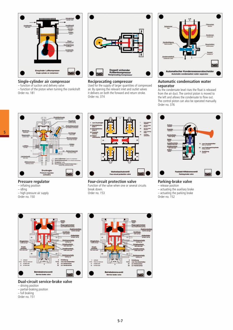
Single-cylinder air compressor– function of suction and delivery valve– function of the piston when turning the crankshaftOrder no. 181
Reciprocating compressorUsed for the supply of larger quantities of compressed air. By opening the relevant inlet and outlet valves it delivers on both the forward and return stroke.Order no. 374
Automatic condensation water separatorAs the condensate level rises the float is released from the air duct. The control piston is moved to the left and allows the condensate to flow out. The control piston can also be operated manually.Order no. 376
Pressure regulator– inflating position– idling– high-pressure air supplyOrder no. 150
Four-circuit protection valveFunction of the valve when one or several circuits break down.Order no. 153
Parking-brake valve– release position– actuating the auxiliary brake– actuating the parking brakeOrder no. 152
Dual-circuit service-brake valve– driving position– partial-braking position– full brakingOrder no. 151
5
5-7
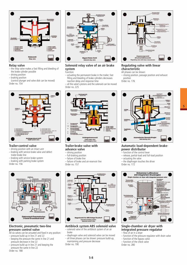
Relay valve– the relay valve makes a fast filling and bleeding of
the brake cylinder possible– driving position– braking position
(control plunger and valve disk can be moved)Order no. 154
Regulating valve with linear characteristicAll phases can be shown: – closing position, passage position and exhaust
positionOrder no. 176
Trailer-control valve– driving position with an intact unit– braking with service-brake valve and defect
trailer-brake line– braking with service brake system– braking with parking brake systemOrder no. 156
Trailer-brake valve with advance valve– driving position– full-braking position– failure of brake line– failure of brake and air-reservoir lineOrder no. 157
Automatic load-dependent brake- power distributor– function of the control lever– release, partial-load and full-load position– actuating the valve– the diaphragm touches the driverOrder no. 172
Electronic, pneumatic two-line pressure control valveAll six valves can be actuated and fixed in any position:– pressure build-up in line 21 and 22 – keeping the pressure the same in line 21 and
pressure decrease in line 22– pressure build-up in line 21 and keeping the
pressure the same in line 22Order no. 188
Antiblock system ABS solenoid valve – solenoid valve of the antiblock system of an air
brake– diaphragm valve and solenoid valve can be moved– all three phases can be shown: pressure build-up,
maintaining and pressure decreaseOrder no. 190
Single-chamber air dryer with integrated pressure regulator– flow of air in a dryer– function of the pressure regulator with drain valve– function of the bypass valve– function of the check valveOrder no. 280
Solenoid relay valve of an air brake systemFunction: – actuating the permanent brake in the trailer; fast
filling and bleeding of brake cylinders decreases reaction delay and response time
– all the valve’s pistons and the solenoid can be movedOrder no. 225
5
5-8
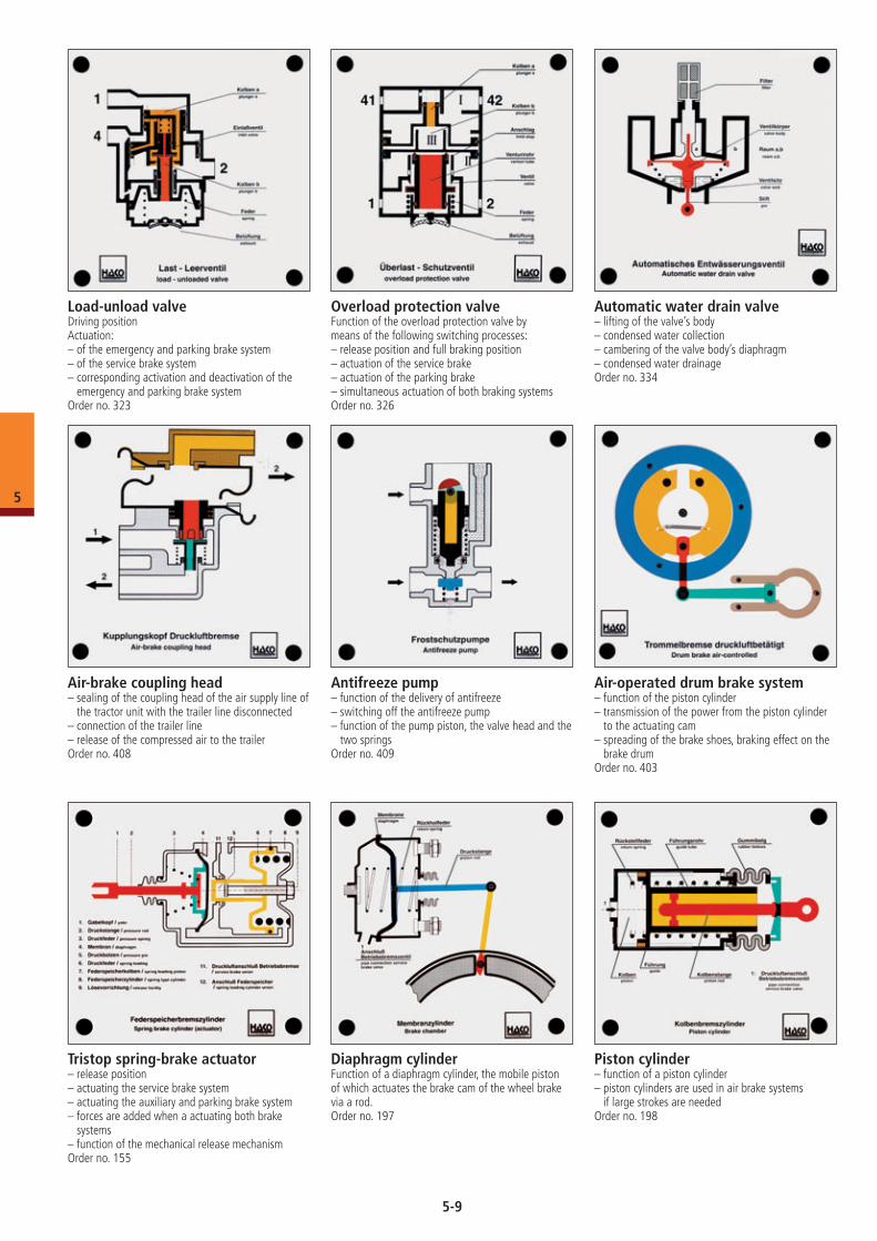
Load-unload valveDriving positionActuation:– of the emergency and parking brake system– of the service brake system– corresponding activation and deactivation of the
emergency and parking brake systemOrder no. 323
Overload protection valveFunction of the overload protection valve bymeans of the following switching processes:– release position and full braking position– actuation of the service brake– actuation of the parking brake– simultaneous actuation of both braking systemsOrder no. 326
Automatic water drain valve– lifting of the valve’s body– condensed water collection– cambering of the valve body’s diaphragm– condensed water drainageOrder no. 334
Tristop spring-brake actuator– release position– actuating the service brake system– actuating the auxiliary and parking brake system– forces are added when a actuating both brake
systems– function of the mechanical release mechanismOrder no. 155
Air-brake coupling head– sealing of the coupling head of the air supply line of
the tractor unit with the trailer line disconnected– connection of the trailer line– release of the compressed air to the trailerOrder no. 408
Antifreeze pump– function of the delivery of antifreeze– switching off the antifreeze pump– function of the pump piston, the valve head and the
two springsOrder no. 409
Air-operated drum brake system– function of the piston cylinder– transmission of the power from the piston cylinder
to the actuating cam– spreading of the brake shoes, braking effect on the
brake drumOrder no. 403
Diaphragm cylinderFunction of a diaphragm cylinder, the mobile piston of which actuates the brake cam of the wheel brake via a rod.Order no. 197
Piston cylinder – function of a piston cylinder– piston cylinders are used in air brake systems
if large strokes are neededOrder no. 198
5
5-9
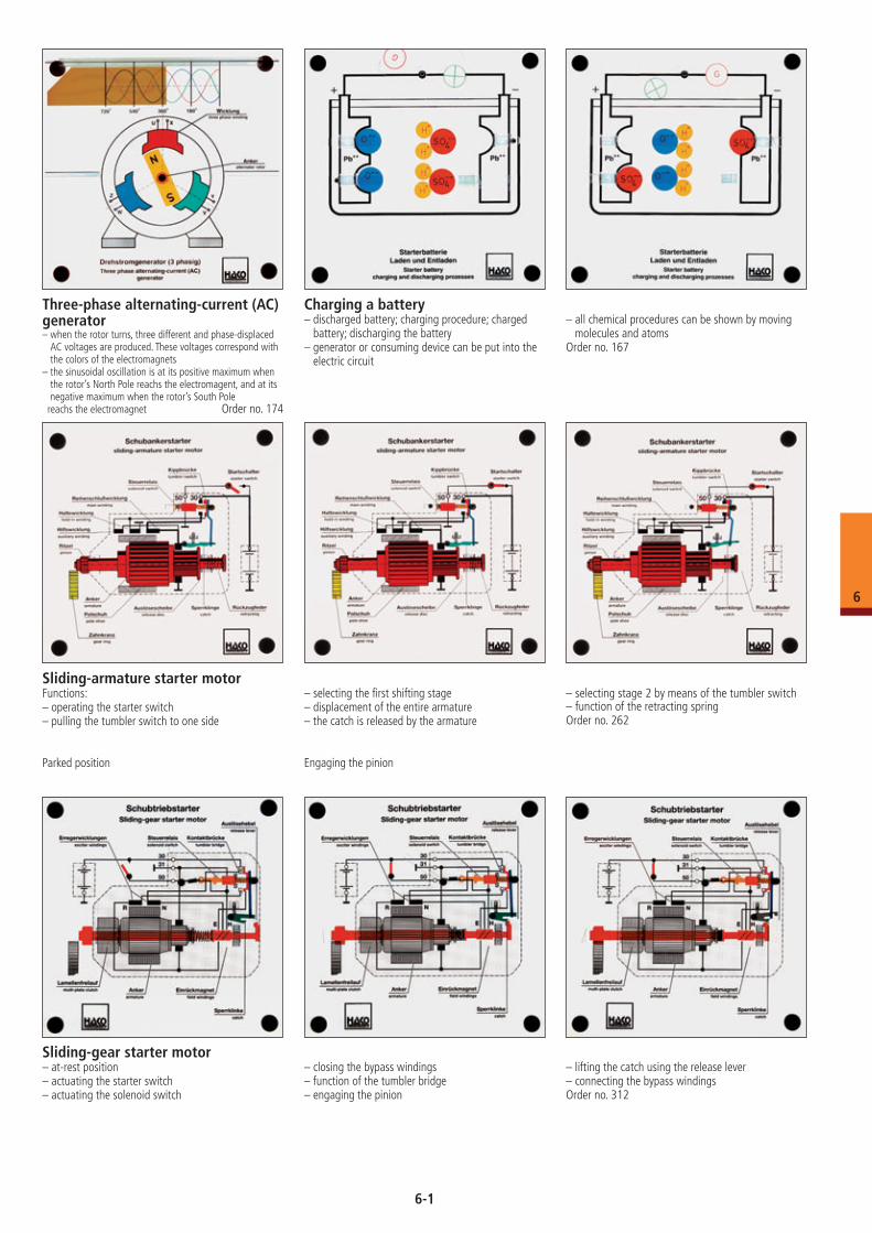
Three-phase alternating-current (AC) generator– when the rotor turns, three different and phase-displaced
AC voltages are produced. These voltages correspond with the colors of the electromagnets
– the sinusoidal oscillation is at its positive maximum when the rotor’s North Pole reachs the electromagent, and at its negative maximum when the rotor’s South Pole
reachs the electromagnet Order no. 174
Charging a battery– discharged battery; charging procedure; charged
battery; discharging the battery– generator or consuming device can be put into the
electric circuit
– all chemical procedures can be shown by moving molecules and atoms
Order no. 167
Sliding-armature starter motorFunctions:– operating the starter switch– pulling the tumbler switch to one side
Parked position
– selecting the first shifting stage– displacement of the entire armature– the catch is released by the armature
Engaging the pinion
– selecting stage 2 by means of the tumbler switch– function of the retracting springOrder no. 262
Sliding-gear starter motor– at-rest position– actuating the starter switch– actuating the solenoid switch
– closing the bypass windings– function of the tumbler bridge– engaging the pinion
– lifting the catch using the release lever– connecting the bypass windingsOrder no. 312
6-1
6
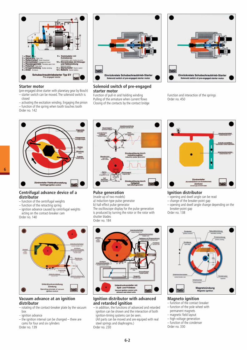
Magneto ignition– function of the contact breaker– function of the pole wheel with
permanent magnets– magnetic field layout– high-voltage generation– function of the condenserOrder no. 330
Solenoid switch of pre-engaged starter motorFunction of pull-in and holding windingPulling of the armature when current flowsClosing of the contacts by the contact bridge
Function and interaction of the springsOrder no. 450
Starter motor(pre-engaged drive starter with planetary gear by Bosch)– starter switch can be moved. The solenoid switch is
closed– activating the excitation winding. Engaging the pinion– function of the spring when tooth touches toothOrder no. 142
Centrifugal advance device of a distributor– function of the centrifugal weights– function of the retracting spring– ignition advance caused by centrifugal weights
acting on the contact-breaker camOrder no. 140
Pulse generation(made-up of two models)a) induction-type pulse generatorb) hall-effect pulse generator The oscilloscope display for the pulse generation is produced by turning the rotor or the rotor with shutter bladesOrder no. 184
Ignition distributor– opening and dwell angle can be read– change of the breaker-point gap– opening and dwell angle change depending on the
breaker-point gapOrder no. 138
Vacuum advance at an ignition distributor– rotating of the contact-breaker plate by the vacuum
box– ignition advance– the ignition interval can be changed – there are
cams for four and six cylindersOrder no. 139
Ignition distributor with advanced and retarded ignition– in addition, the functions of advanced and retarded
ignition can be shown and the interaction of both ignition-timing systems can be seen. (All parts can be moved and are equiped with real steel springs and diaphragms.)
Order no. 230
6-2
6
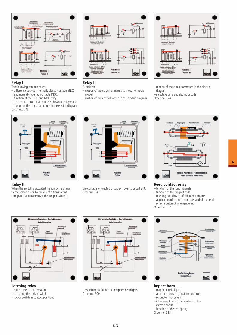
Relay IThe following can be shown:– difference between normally closed contacts (NCC)
and normally opened contacts (NOC)– function of the NCC and NOC relay– motion of the curcuit armature is shown on relay model– motion of the curcuit armature in the electric diagramOrder no. 273
Relay IIFunctions:– motion of the curcuit armature is shown on relay
model– motion of the control switch in the electric diagram
– motion of the curcuit armature in the electric diagram
– selecting different electric circuitsOrder no. 274
Relay IIIWhen the switch is actuated the jumper is drawn to the solenoid coil by means of a transparent cam plate. Simultaneously, the jumper switches
the contacts of electric circuit 2-1 over to circuit 2-3.Order no. 341
Reed contact relay– function of the foric magnets– function of the magnet coils– opening and closing of the reed contacts– application of the reed contacts and of the reed
relay in automotive engineeringOrder no. 357
Latching relay– pulling the circuit armature– actuating the rocker switch– rocker switch in contact positions
– switching to full beam or dipped headlightsOrder no. 300
Impact horn– magnetic field layout– armature stroke against iron coil core– resonator movement– CI interruption and connection of the
electric circuit– function of the leaf springOrder no. 333
6-3
6
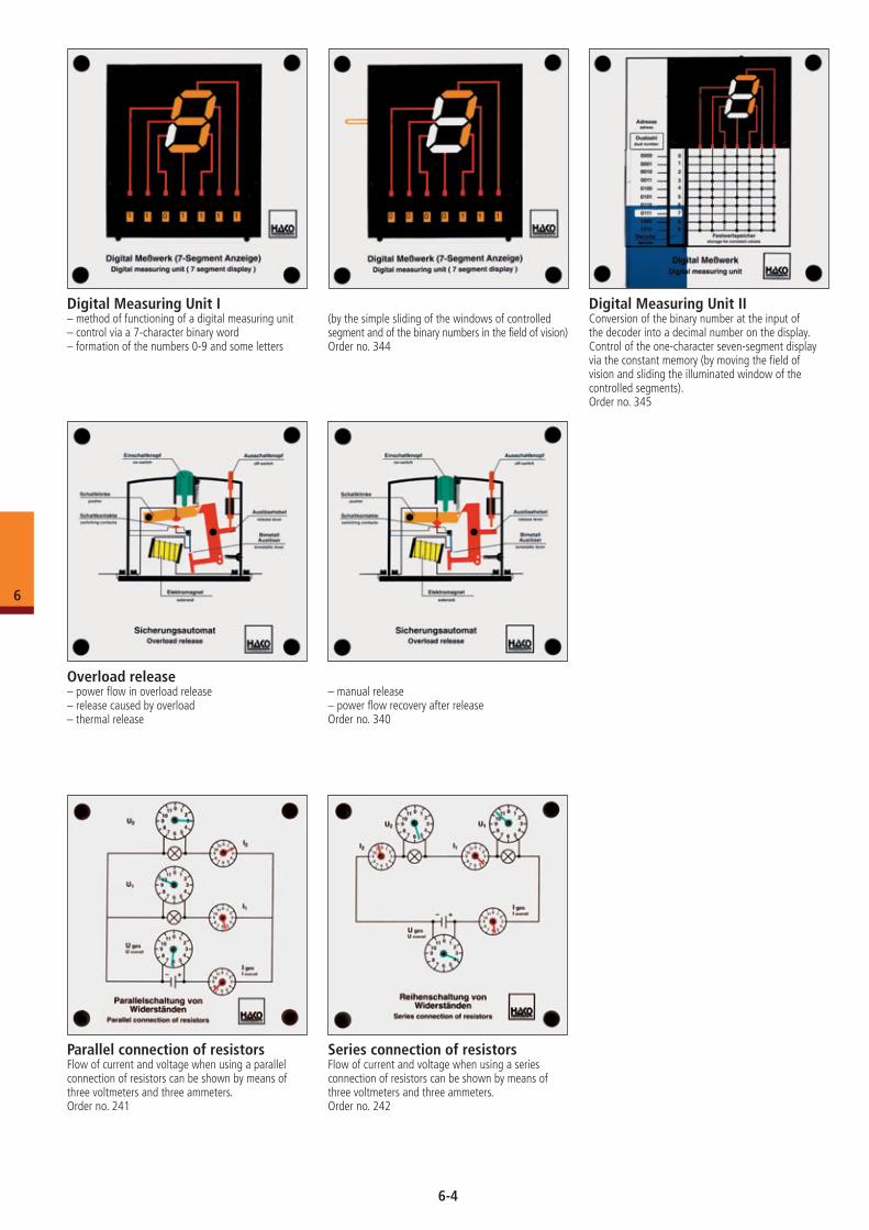
Digital Measuring Unit I– method of functioning of a digital measuring unit – control via a 7-character binary word– formation of the numbers 0-9 and some letters
Digital Measuring Unit IIConversion of the binary number at the input of the decoder into a decimal number on the display.Control of the one-character seven-segment display via the constant memory (by moving the field of vision and sliding the illuminated window of the controlled segments).Order no. 345
(by the simple sliding of the windows of controlled segment and of the binary numbers in the field of vision)Order no. 344
Overload release– power flow in overload release– release caused by overload– thermal release
– manual release– power flow recovery after releaseOrder no. 340
Parallel connection of resistorsFlow of current and voltage when using a parallel connection of resistors can be shown by means of three voltmeters and three ammeters.Order no. 241
Series connection of resistorsFlow of current and voltage when using a series connection of resistors can be shown by means of three voltmeters and three ammeters.Order no. 242
6-4
6
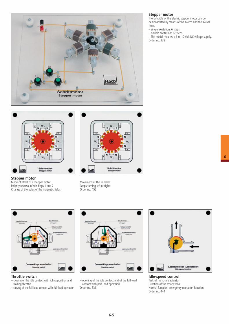
Stepper motorThe principle of the electric stepper motor can be demonstrated by means of the switch and the swivel rotor.– single excitation: 6 steps– double excitation: 12 steps
The model requires a 6 to 10 Volt DC voltage supply.Order no. 332
Stepper motorMode of effect of a stepper motorPolarity reversal of windings 1 and 2Change of the poles of the magnetic fields
Movement of the impeller (steps turning left or right)Order no. 452
Idle-speed controlTask of the rotary actuatorFunction of the rotary valveNormal function, emergency operation functionOrder no. 444
Throttle switch– closing of the idle contact with idling position and
trailing throttle– closing of the full-load contact with full-load operation
– opening of the idle contact and of the full-load contact with part load operation
Order no. 336
6-5
6
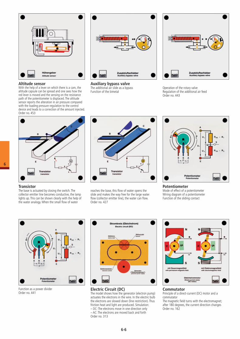
Auxiliary bypass valveThe additional air slide as a bypassFunction of the bimetal
Operation of the rotary valveRegulation of the additional air feedOrder no. 443
Altitude sensorWith the help of a lever on which there is a cam, the altitude capsule can be spread and one sees how the red lever is moved and the sensing on the resistance path of the potentiometer is displaced. The altitude sensor reports the alteration in air pressure compared with the loading pressure regulation to the control device and leads to a correction of the amount injected.Order no. 453
CommutatorPrinciple of a direct-current (DC) motor and a commutatorThe magnetic field turns with the electromagnet; after 180 degrees, the current direction changesOrder no. 162
Electric Circuit (DC)The model shows how the generator (electron pump) actuates the electrons in the wire. In the electric bulb the electrons are slowed down (line restriction). Thus friction heat and light are produced. Simulation:– DC: The electrons move in one direction only– AC: The electrons are moved back and forthOrder no. 313
PotentiometerMode of effect of a potentiometerWiring diagram of a potentiometerFunction of the sliding contact
Function as a power dividerOrder no. 441
TransistorThe base is actuated by closing the switch. The collector emitter line becomes conductive, the lamp lights up. This can be shown clearly with the help of the water analogy. When the small flow of water
reaches the base, this flow of water opens the slide and makes the way free for the large water flow (collector emitter line), the water can flow. Order no. 427
6-6
6
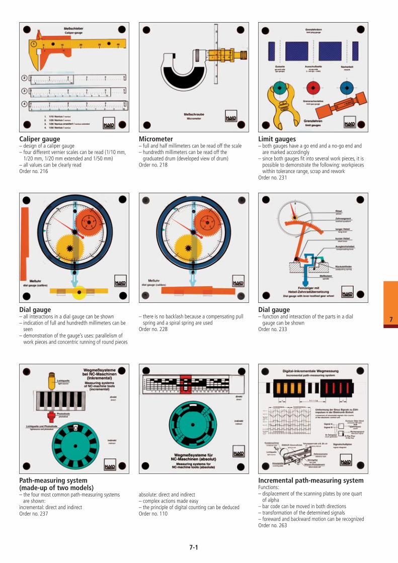
Caliper gauge– design of a caliper gauge– four different vernier scales can be read (1/10 mm,
1/20 mm, 1/20 mm extended and 1/50 mm)– all values can be clearly readOrder no. 216
Micrometer– full and half millimeters can be read off the scale– hundredth millimeters can be read off the
graduated drum (developed view of drum)Order no. 218
Limit gauges– both gauges have a go end and a no-go end and
are marked accordingly– since both gauges fit into several work pieces, it is
possible to demonstrate the following: workpieces within tolerance range, scrap and rework
Order no. 231
Dial gauge – all interactions in a dial gauge can be shown– indication of full and hundredth millimeters can be
seen– demonstration of the gauge’s uses: parallelism of
work pieces and concentric running of round pieces
– there is no backlash because a compensating pull spring and a spiral spring are used
Order no. 228
Dial gauge– function and interaction of the parts in a dial
gauge can be shownOrder no. 233
Path-measuring system(made-up of two models)– the four most common path-measuring systems
are shown:incremental: direct and indirectOrder no. 237
absolute: direct and indirect – complex actions made easy– the principle of digital counting can be deducedOrder no. 110
Incremental path-measuring systemFunctions:– displacement of the scanning plates by one quart
of alpha– bar code can be moved in both directions– transformation of the determined signals– foreward and backward motion can be recognizedOrder no. 263
7-1
7
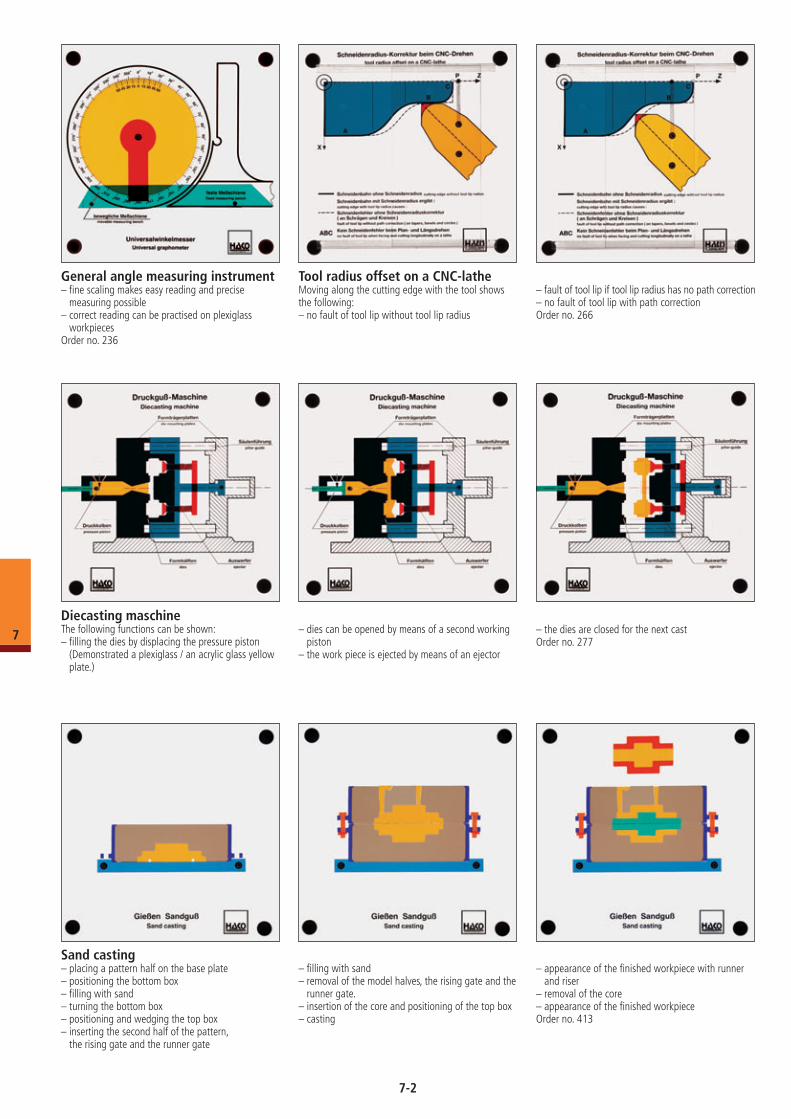
General angle measuring instrument– fine scaling makes easy reading and precise
measuring possible– correct reading can be practised on plexiglass
workpiecesOrder no. 236
Sand casting– placing a pattern half on the base plate– positioning the bottom box– filling with sand– turning the bottom box– positioning and wedging the top box– inserting the second half of the pattern,
the rising gate and the runner gate
– filling with sand– removal of the model halves, the rising gate and the
runner gate.– insertion of the core and positioning of the top box– casting
– appearance of the finished workpiece with runner and riser
– removal of the core– appearance of the finished workpieceOrder no. 413
Tool radius offset on a CNC-latheMoving along the cutting edge with the tool shows the following:– no fault of tool lip without tool lip radius
– fault of tool lip if tool lip radius has no path correction– no fault of tool lip with path correctionOrder no. 266
Diecasting maschineThe following functions can be shown:– filling the dies by displacing the pressure piston
(Demonstrated a plexiglass / an acrylic glass yellow plate.)
– dies can be opened by means of a second working piston
– the work piece is ejected by means of an ejector
– the dies are closed for the next castOrder no. 277
7-2
7
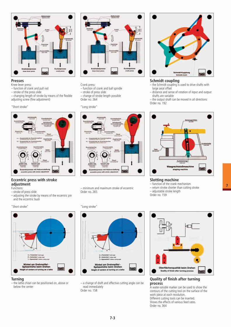
PressesKnee-lever press:– function of crank and pull rod– stroke of the press slide– changing length of stroke by means of the flexible adjusting screw (fine adjustment)
"Short stroke"
Crank press:– function of crank and ball spindle– stroke of press slide– change of stroke length possibleOrder no. 264
"Long stroke"
Schmidt coupling– the Schmidt coupling is used to drive shafts with
large axial offset– distance and sense of rotation of input and output
shafts are variable– the output shaft can be moved in all directionsOrder no. 192
Eccentric press with stroke adjustmentFunctions:– stroke of press slide– adjusting the stroke by means of the eccentric pin
and the eccentric bush
"Short stroke"
– minimum and maximum stroke of eccentricOrder no. 265
"Long stroke"
Slotting machine– function of the crank mechanism– return stroke shorter than cutting stroke– adjustable stroke lengthOrder no. 159
Turning– the lathe chisel can be positioned on, above or
below the center– a change of draft and effective cutting angle can be
read immediatelyOrder no. 158
Quality of finish after turning processA water-soluble marker can be used to show the contours of the cutting tool on the surface of the work piece at each revolution.Different cutting tools can be inserted.Shows the effects of various feed rates.Order no. 364
7-3
7
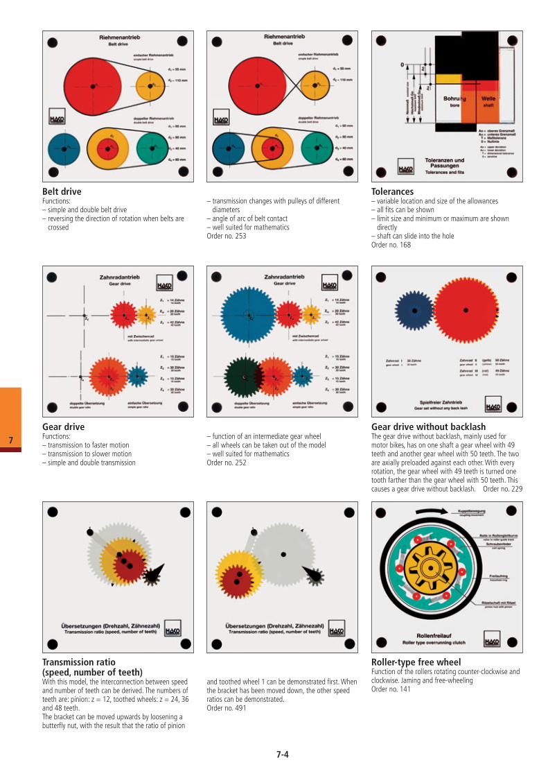
Belt driveFunctions:– simple and double belt drive– reversing the direction of rotation when belts are
crossed
– transmission changes with pulleys of different diameters
– angle of arc of belt contact– well suited for mathematicsOrder no. 253
Tolerances– variable location and size of the allowances– all fits can be shown– limit size and minimum or maximum are shown
directly– shaft can slide into the holeOrder no. 168
Gear driveFunctions:– transmission to faster motion– transmission to slower motion– simple and double transmission
– function of an intermediate gear wheel– all wheels can be taken out of the model– well suited for mathematicsOrder no. 252
Roller-type free wheelFunction of the rollers rotating counter-clockwise and clockwise. Jaming and free-wheelingOrder no. 141
Transmission ratio (speed, number of teeth)With this model, the interconnection between speed and number of teeth can be derived. The numbers of teeth are: pinion: z = 12, toothed wheels: z = 24, 36 and 48 teeth.The bracket can be moved upwards by loosening a butterfly nut, with the result that the ratio of pinion
and toothed wheel 1 can be demonstrated first. When the bracket has been moved down, the other speed ratios can be demonstrated.Order no. 491
Gear drive without backlashThe gear drive without backlash, mainly used for motor bikes, has on one shaft a gear wheel with 49 teeth and another gear wheel with 50 teeth. The two are axially preloaded against each other. With every rotation, the gear wheel with 49 teeth is turned one tooth farther than the gear wheel with 50 teeth. This causes a gear drive without backlash. Order no. 229
7-4
7
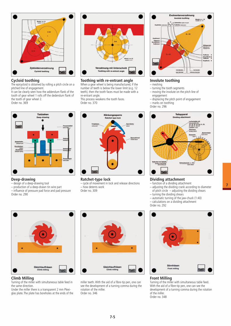
Involute toothing– meshing– turning the tooth segments– moving the involute on the pitch line of
engagement– displacing the pitch point of engagement– marks on toothingOrder no. 296
Cycloid toothingThe epicycloid is obtained by rolling a pitch circle on a pitched line of engagement.It can be clearly seen how the addendum flank of the tooth of gear wheel 1 rolls off the dedendum flank of the tooth of gear wheel 2.Order no. 369
Toothing with re-entrant angleWhen a gear wheel is being manufactured, if the number of teeth is below the lower limit (e.g. 12 teeth), then the tooth faces must be made with a re-entrant angle.This process weakens the tooth faces.Order no. 370
Deep-drawing– design of a deep-drawing tool– production of a deep-drawn tin wire part– influence of pressure pad force and pad pressureOrder no. 290
Ratchet-type lock– cycle of movement in lock and release directions– how detents workOrder no. 309
Dividing attachment– function of a dividing attachment– adjusting the dividing crank according to diameter
of pitch circle – adjusting the dividing shears– turning the dividing shears– automatic turning of the jaw-chuck (1:40)– calculations on a dividing attachmentOrder no. 292
Climb MillingTurning of the miller with simultaneous table feed in the same direction.Under the miller there is a transparent 2 mm Plexi-glas plate. The plate has boreholes at the ends of the
miller teeth. With the aid of a fibre-tip pen, one can see the development of a turning comma during the rotation of the miller.Order no. 346
Front MillingTurning of the miller with simultaneous table feed.With the aid of a fibre-tip pen, one can see the development of a turning comma during the rotation of the miller.Order no. 348
7-5
7
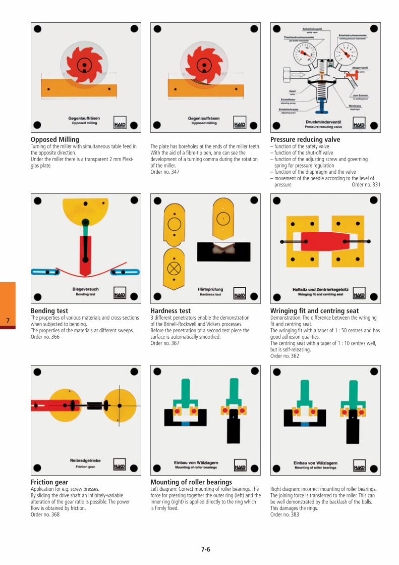
Opposed MillingTurning of the miller with simultaneous table feed in the opposite direction.Under the miller there is a transparent 2 mm Plexi-glas plate.
The plate has boreholes at the ends of the miller teeth. With the aid of a fibre-tip pen, one can see the development of a turning comma during the rotation of the miller.Order no. 347
Pressure reducing valve– function of the safety valve– function of the shut-off valve– function of the adjusting screw and governing
spring for pressure regulation– function of the diaphragm and the valve– movement of the needle according to the level of
pressure Order no. 331
Bending testThe properties of various materials and cross-sections when subjected to bending.The properties of the materials at different sweeps.Order no. 366
Hardness test3 different penetrators enable the demonstration of the Brinell-Rockwell and Vickers processes.Before the penetration of a second test piece the surface is automatically smoothed.Order no. 367
Wringing fit and centring seatDemonstration: The difference between the wringing fit and centring seat.The wringing fit with a taper of 1 : 50 centres and has good adhesion qualities.The centring seat with a taper of 1 : 10 centres well, but is self-releasing.Order no. 362
Friction gearApplication for e.g. screw presses.By sliding the drive shaft an infinitely-variable alteration of the gear ratio is possible. The power flow is obtained by friction.Order no. 368
Mounting of roller bearingsLeft diagram: Correct mounting of roller bearings. The force for pressing together the outer ring (left) and the inner ring (right) is applied directly to the ring which is firmly fixed.
Right diagram: incorrect mounting of roller bearings.The joining force is transferred to the roller. This can be well demonstrated by the backlash of the balls. This damages the rings.Order no. 383
7-6
7
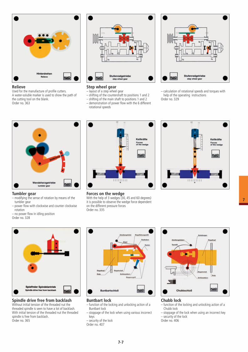
RelieveUsed for the manufacture of profile cutters.A water-soluble marker is used to show the path of the cutting tool on the blank.Order no. 363
Step wheel gear– layout of a step wheel gear– shifting of the countershaft to positions 1 and 2– shifting of the main shaft to positions 1 and 2– demonstration of power flow with the 6 different
rotational speeds
– calculation of rotational speeds and torques with help of the operating instructions
Order no. 329
Buntbart lock– function of the locking and unlocking action of a
Buntbart lock– stoppage of the lock when using various incorrect
keys– security of the lockOrder no. 407
Chubb lock– function of the locking and unlocking action of a
Chubb lock– stoppage of the lock when using an incorrect key– security of the lockOrder no. 406
Tumbler gear– modifying the sense of rotation by means of the
tumbler gear– power flow with clockwise and counter clockwise
rotation– no power flow in idling positionOrder no. 328
Forces on the wedgeWith the help of 3 wedges (30, 45 and 60 degrees) it is possible to observe the wedge force dependent on the different pressure forcesOrder no. 335
Spindle drive free from backlashWithout initial tension of the threaded nut the threaded spindle is seen to have a lot of backlash.With initial tension of the threaded nut the threaded spindle is free from backlash.Order no. 365
7-7
7
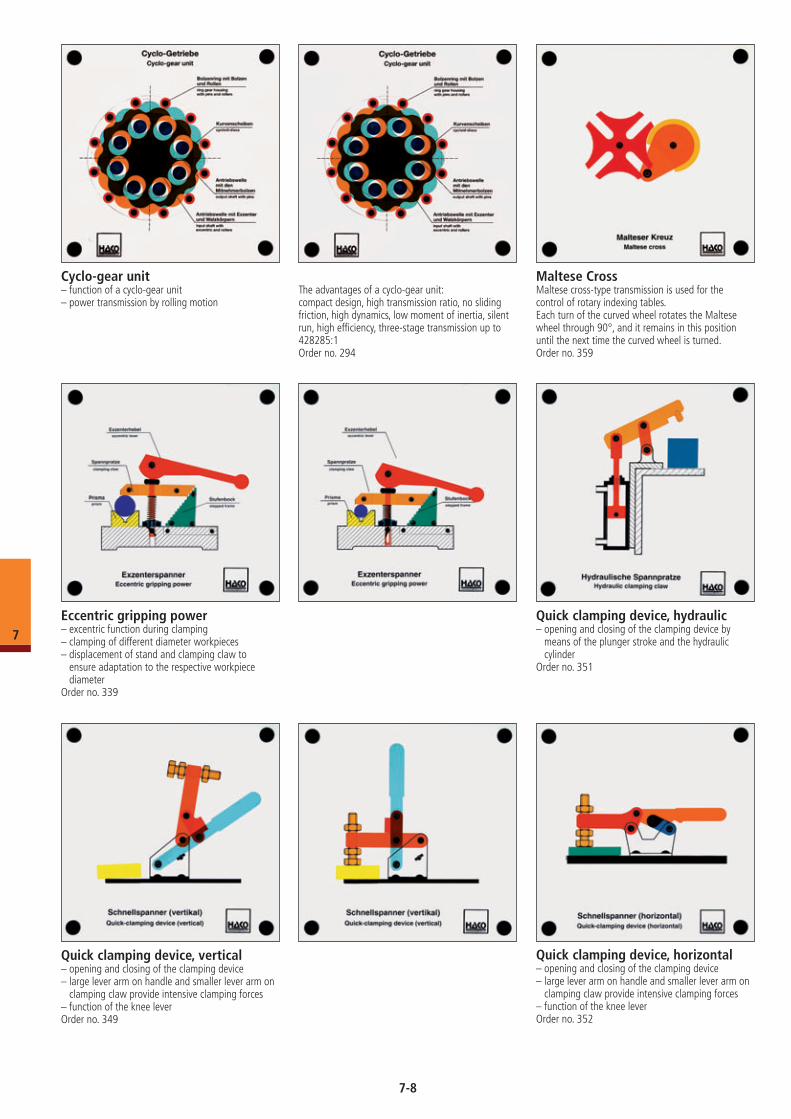
Maltese CrossMaltese cross-type transmission is used for the control of rotary indexing tables.Each turn of the curved wheel rotates the Maltese wheel through 90°, and it remains in this position until the next time the curved wheel is turned.Order no. 359
Cyclo-gear unit– function of a cyclo-gear unit– power transmission by rolling motion
The advantages of a cyclo-gear unit: compact design, high transmission ratio, no sliding friction, high dynamics, low moment of inertia, silent run, high efficiency, three-stage transmission up to 428285:1Order no. 294
Eccentric gripping power– excentric function during clamping– clamping of different diameter workpieces– displacement of stand and clamping claw to
ensure adaptation to the respective workpiece diameter
Order no. 339
Quick clamping device, hydraulic– opening and closing of the clamping device by
means of the plunger stroke and the hydraulic cylinder
Order no. 351
Quick clamping device, vertical– opening and closing of the clamping device– large lever arm on handle and smaller lever arm on
clamping claw provide intensive clamping forces– function of the knee leverOrder no. 349
Quick clamping device, horizontal– opening and closing of the clamping device– large lever arm on handle and smaller lever arm on
clamping claw provide intensive clamping forces– function of the knee leverOrder no. 352
7-8
7
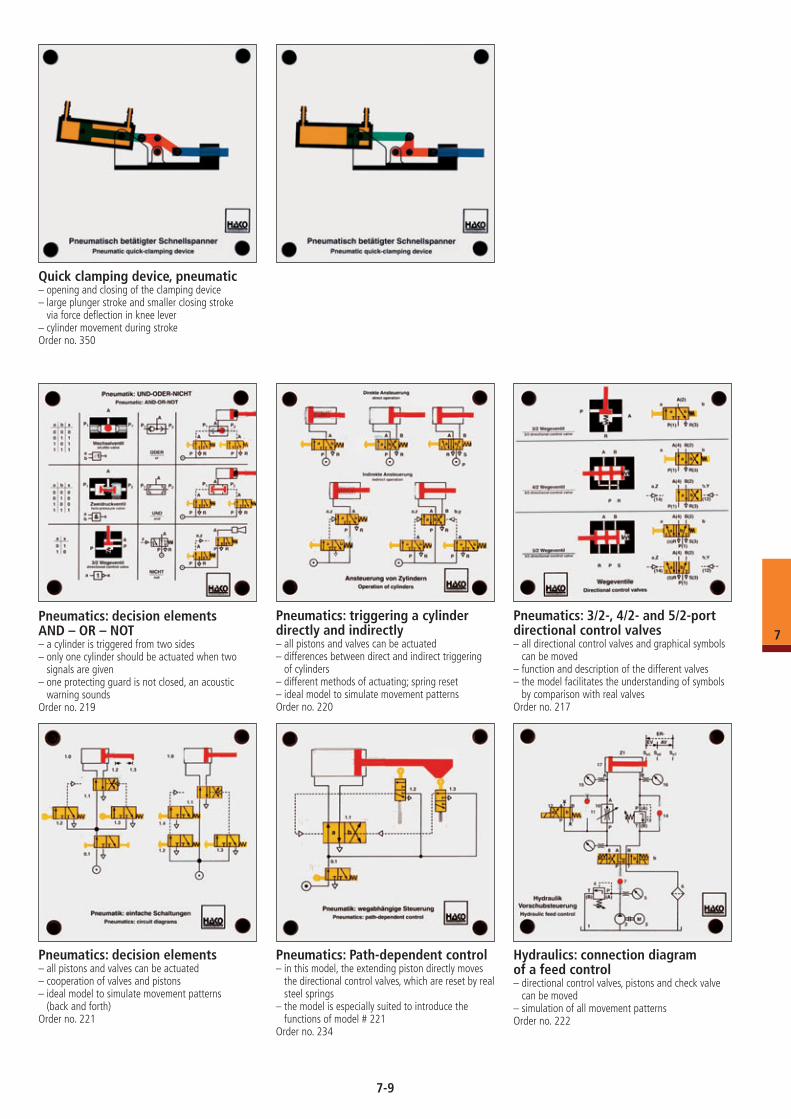
Quick clamping device, pneumatic– opening and closing of the clamping device– large plunger stroke and smaller closing stroke
via force deflection in knee lever– cylinder movement during strokeOrder no. 350
Pneumatics: decision elements AND – OR – NOT– a cylinder is triggered from two sides– only one cylinder should be actuated when two
signals are given– one protecting guard is not closed, an acoustic
warning soundsOrder no. 219
Pneumatics: triggering a cylinder directly and indirectly– all pistons and valves can be actuated– differences between direct and indirect triggering
of cylinders– different methods of actuating; spring reset– ideal model to simulate movement patternsOrder no. 220
Pneumatics: 3/2-, 4/2- and 5/2-port directional control valves– all directional control valves and graphical symbols
can be moved– function and description of the different valves– the model facilitates the understanding of symbols
by comparison with real valvesOrder no. 217
Pneumatics: decision elements– all pistons and valves can be actuated– cooperation of valves and pistons– ideal model to simulate movement patterns
(back and forth)Order no. 221
Pneumatics: Path-dependent control – in this model, the extending piston directly moves
the directional control valves, which are reset by real steel springs
– the model is especially suited to introduce the functions of model # 221
Order no. 234
Hydraulics: connection diagram of a feed control – directional control valves, pistons and check valve
can be moved– simulation of all movement patternsOrder no. 222
7-9
7
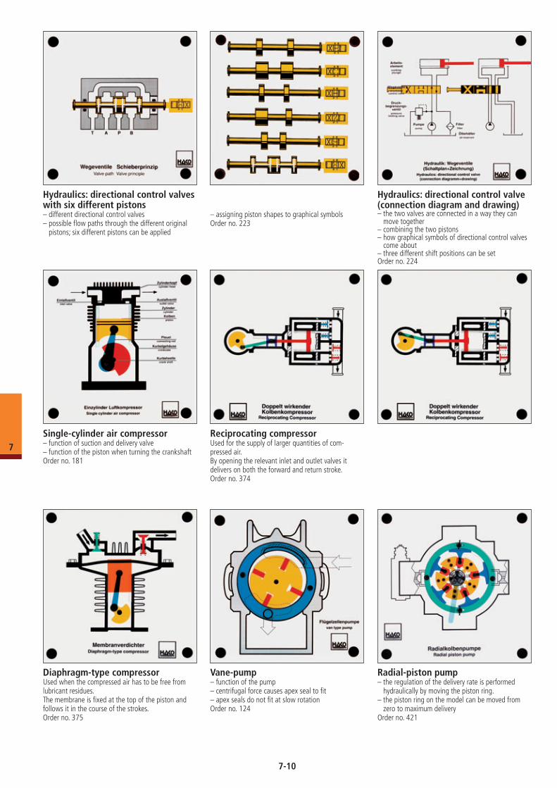
Hydraulics: directional control valves with six different pistons– different directional control valves– possible flow paths through the different original
pistons; six different pistons can be applied
– assigning piston shapes to graphical symbolsOrder no. 223
Hydraulics: directional control valve (connection diagram and drawing)– the two valves are connected in a way they can
move together– combining the two pistons– how graphical symbols of directional control valves
come about– three different shift positions can be setOrder no. 224
Radial-piston pump– the regulation of the delivery rate is performed
hydraulically by moving the piston ring.– the piston ring on the model can be moved from
zero to maximum deliveryOrder no. 421
Single-cylinder air compressor– function of suction and delivery valve– function of the piston when turning the crankshaftOrder no. 181
Reciprocating compressorUsed for the supply of larger quantities of com- pressed air.By opening the relevant inlet and outlet valves it delivers on both the forward and return stroke.Order no. 374
Diaphragm-type compressorUsed when the compressed air has to be free from lubricant residues.The membrane is fixed at the top of the piston and follows it in the course of the strokes.Order no. 375
Vane-pump– function of the pump– centrifugal force causes apex seal to fit– apex seals do not fit at slow rotationOrder no. 124
7-10
7
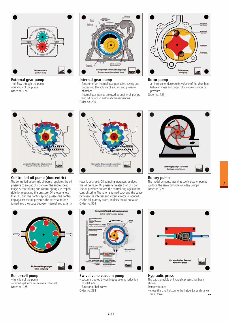
External gear pump– oil flow through the pump– function of the pumpOrder no. 128
Rotor pump– an increase or decrease in volume of the chambers
between inner and outer rotor causes suction or pressure
Order no. 129
Internal gear pump– function of an internal gear pump: increasing and
decreasing the volume of suction and pressure chamber
– internal gear pumps are used as engine-oil pumps and oil pumps in automatic transmissions
Order no. 206
Hydraulic pressThe basic principle of hydraulic presses has been shown.Demonstration:– move the small piston to the inside. Large distance,
small force
Controlled oil pump (duocentric)The controlled duocentric oil pump regulates the oil pressure to around 3.5 bar over the entire speed range. A control ring and control spring are respon-sible for regulating the pressure. Oil pressure less than 3.5 bar: The control spring presses the control ring against the oil pressure, the external rotor is turned and the space between internal and external
rotor is enlarged. Oil pumping increases, as does the oil pressure. Oil pressure greater than 3.5 bar: The oil pressure presses the control ring against the control spring. The rotor is turned back and the space between the internal and external rotor is reduced. As the oil quantity drops, so does the oil pressure.Order no. 506
Rotary pumpThe model demonstrates that cooling-water pumps work on the same principle as rotary pumps.Order no. 226
Roller-cell pump– function of the pump– centrifugal force causes rollers to sealOrder no. 125
Swivel vane vacuum pump– vacuum created by continuous volume reduction
of inlet side– function of ball valvesOrder no. 288
7-11
7
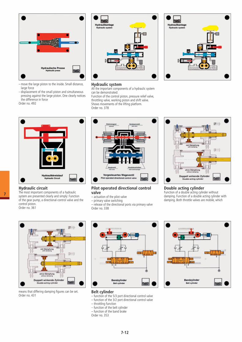
– move the large piston to the inside. Small distance, large force
– displacement of the small piston and simultaneous pressing against the large piston. One clearly notices the difference in force
Order no. 492
Hydraulic circuitThe most important components of a hydraulic system are presented clearly and simply: Function of the gear pump, a directional-control valve and the control piston.Order no. 361
Hydraulic systemAll the important components of a hydraulic system can be demonstrated:Function of the control piston, pressure relief valve, throttling valve, working piston and shift valve.Shows movements of the lifting platform.Order no. 378
Pilot operated directional control valve– actuation of the pilot valve– primary valve switching– release of the directional ports via primary valveOrder no. 338
Double acting cylinderFunction of a double acting cylinder without damping. Function of a double acting cylinder with damping. Both throttle valves are mobile, which
means that differing damping figures can be set.Order no. 431
Belt cylinder– function of the 5/3 port directional control valve– function of the 3/2 port directional control valve– throttling function– function of the belt cylinder– function of the band brakeOrder no. 353
7-12
7
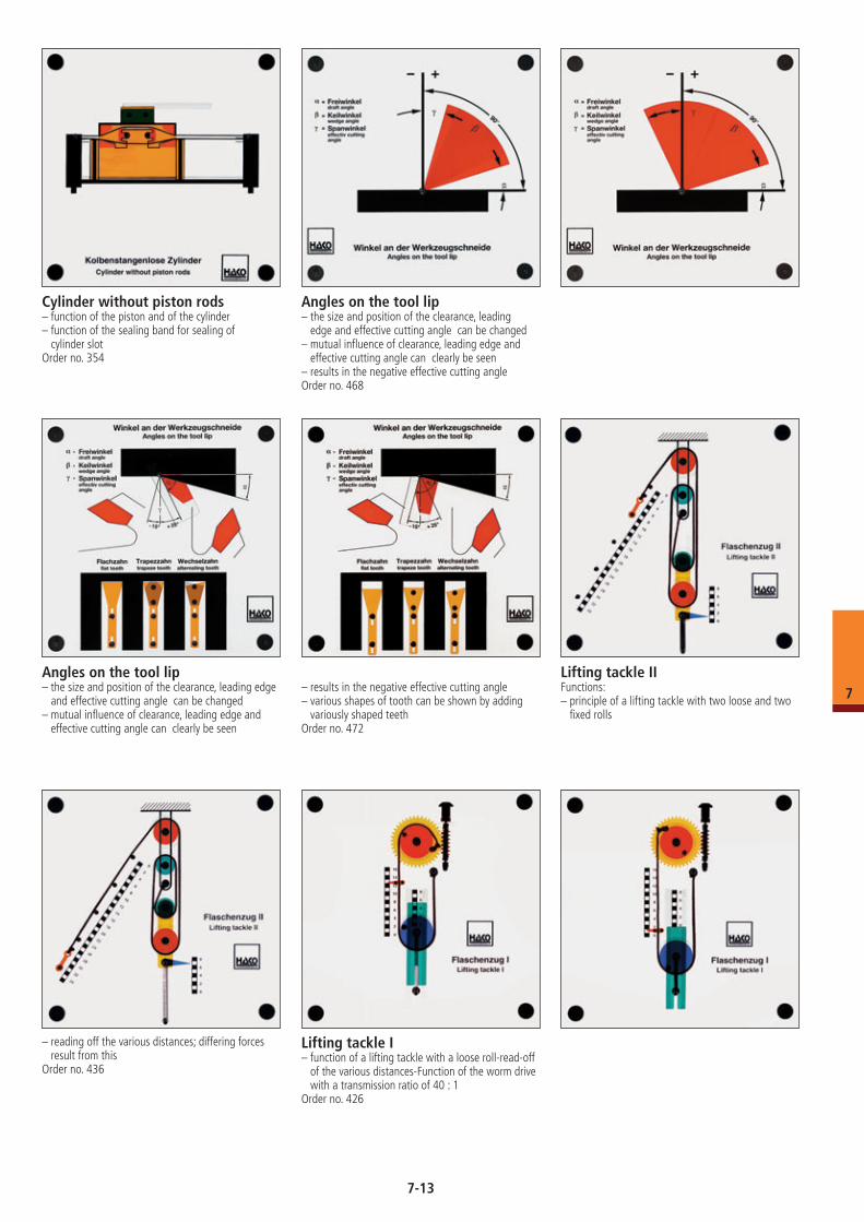
Cylinder without piston rods– function of the piston and of the cylinder– function of the sealing band for sealing of
cylinder slotOrder no. 354
Angles on the tool lip– the size and position of the clearance, leading
edge and effective cutting angle can be changed– mutual influence of clearance, leading edge and
effective cutting angle can clearly be seen– results in the negative effective cutting angleOrder no. 468
Angles on the tool lip– the size and position of the clearance, leading edge
and effective cutting angle can be changed– mutual influence of clearance, leading edge and
effective cutting angle can clearly be seen
– results in the negative effective cutting angle– various shapes of tooth can be shown by adding
variously shaped teethOrder no. 472
Lifting tackle I– function of a lifting tackle with a loose roll-read-off
of the various distances-Function of the worm drive with a transmission ratio of 40 : 1
Order no. 426
Lifting tackle IIFunctions:– principle of a lifting tackle with two loose and two
fixed rolls
– reading off the various distances; differing forces result from this
Order no. 436
7-13
7
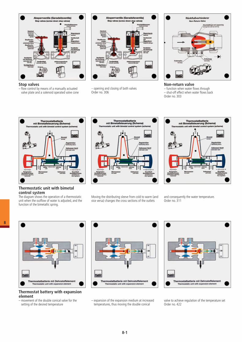
Thermostat battery with expansion element– movement of the double conical valve for the
setting of the desired temperature– expansion of the expansion medium at increased
temperatures, thus moving the double conical valve to achieve regulation of the temperature setOrder no. 422
Stop valves– flow control by means of a manually actuated
valve plate and a solenoid operated valve cone– opening and closing of both valvesOrder no. 306
Non-return valve– function when water flows through– shut-off effect when water flows backOrder no. 303
Thermostatic unit with bimetal control systemThe diagram shows the operation of a thermostatic unit when the outflow of water is adjusted, and the function of the bimetallic spring.
Moving the distributing sleeve from cold to warm (and vice versa) changes the cross sections of the outlets
and consequently the water temperature.Order no. 311
8
8-1
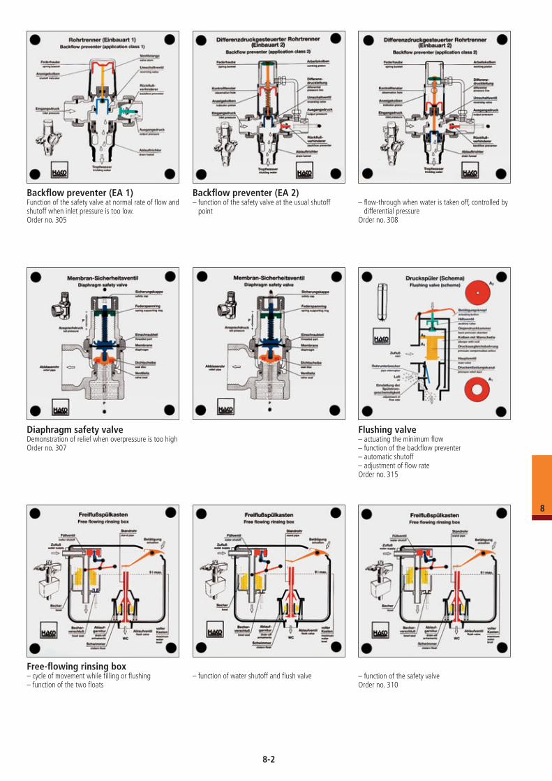
Backflow preventer (EA 1)Function of the safety valve at normal rate of flow and shutoff when inlet pressure is too low.Order no. 305
Backflow preventer (EA 2)– function of the safety valve at the usual shutoff
point– flow-through when water is taken off, controlled by
differential pressureOrder no. 308
Diaphragm safety valveDemonstration of relief when overpressure is too highOrder no. 307
Flushing valve– actuating the minimum flow– function of the backflow preventer– automatic shutoff– adjustment of flow rateOrder no. 315
Free-flowing rinsing box– cycle of movement while filling or flushing– function of the two floats
– function of water shutoff and flush valve – function of the safety valveOrder no. 310
8
8-2
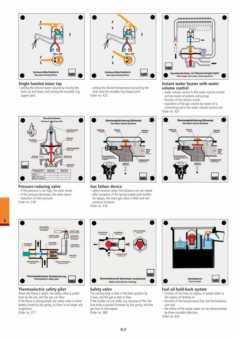
Pressure-reducing valve– if the pressure is too high, the valve closes– if the pressure decreases, the valve opens– reduction of inlet pressureOrder no. 318
Single-handed mixer tap– setting the desired water volume by moving the
lever up and down and turning the movable ring (upper part)
Instant water heater with water volume control– water volume control in the water volume control
unit by means of pistons and springs– function of the Venturi nozzle– regulation of the gas volume by means of a
connecting rod to the water volume control unitOrder no. 425
Fuel oil hold-back system– function of the float on ingress of waste water or
the ingress of heating oil– function of the backpressure flap and the backpres-
sure seal– the inflow of the waste water can be demonstrated
by three movable slide barsOrder no. 424
– setting the desired temperature by turning the lever and the movable ring (lower part)
Order no. 423
Gas failure device– safety function when line divisions are not closed– after actuation of the spring loaded push-button
for bypass, the main gas-valve is lifted and rest pressure increases
Order no. 316
Thermoelectric safety pilotWhen the flame is alight, the safety valve is pulled back by the coil, and the gas can flow.If the flame is extinguished, the safety valve is imme-diately closed by the spring, as there is no longer any magnetism.Order no. 377
Safety valveThe closing body is held in the back position by a fuse, and the gas is able to flow.If the fusible cut out melts, e.g. because of fire, the fuse body is pushed forwards by the spring, and the gas flow is interrupted.Order no. 380
8
8-3
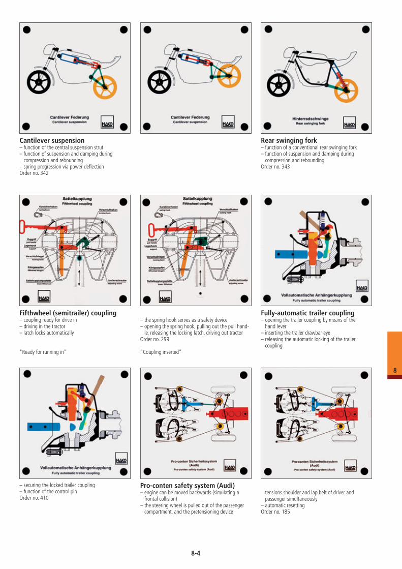
Fully-automatic trailer coupling – opening the trailer coupling by means of the
hand lever– inserting the trailer drawbar eye– releasing the automatic locking of the trailer
coupling
– securing the locked trailer coupling– function of the control pinOrder no. 410
Cantilever suspension– function of the central suspension strut– function of suspension and damping during
compression and rebounding– spring progression via power deflectionOrder no. 342
Rear swinging fork– function of a conventional rear swinging fork– function of suspension and damping during
compression and reboundingOrder no. 343
Fifthwheel (semitrailer) coupling– coupling ready for drive in– driving in the tractor– latch locks automatically
"Ready for running in"
– the spring hook serves as a safety device– opening the spring hook, pulling out the pull hand-
le, releasing the locking latch, driving out tractorOrder no. 299
"Coupling inserted"
Pro-conten safety system (Audi)– engine can be moved backwards (simulating a
frontal collision)– the steering wheel is pulled out of the passenger
compartment, and the pretensioning device
tensions shoulder and lap belt of driver and passenger simultaneously
– automatic resettingOrder no. 185
8
8-4
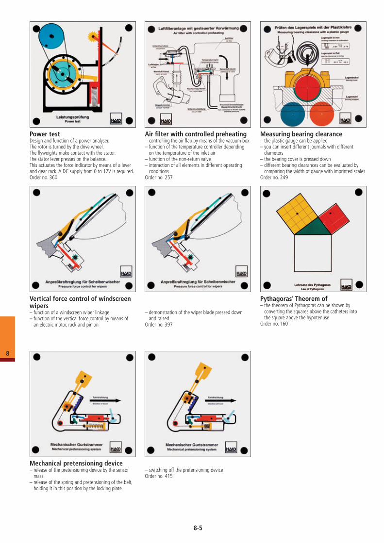
Vertical force control of windscreen wipers– function of a windscreen wiper linkage– function of the vertical force control by means of
an electric motor, rack and pinion
– demonstration of the wiper blade pressed down and raised
Order no. 397
Power testDesign and function of a power analyser.The rotor is turned by the drive wheel.The flyweights make contact with the stator.The stator lever presses on the balance.This actuates the force indicator by means of a lever and gear rack. A DC supply from 0 to 12V is required.Order no. 360
Air filter with controlled preheating– controlling the air flap by means of the vacuum box– function of the temperature controller depending
on the temperature of the inlet air– function of the non-return valve– interaction of all elements in different operating
conditionsOrder no. 257
Measuring bearing clearance– the plastic gauge can be applied– you can insert different journals with different
diameters– the bearing cover is pressed down– different bearing clearances can be evaluated by
com paring the width of gauge with imprinted scalesOrder no. 249
Pythagoras’ Theorem of– the theorem of Pythagoras can be shown by
converting the squares above the catheters into the square above the hypotenuse
Order no. 160
Mechanical pretensioning device– release of the pretensioning device by the sensor
mass– release of the spring and pretensioning of the belt,
holding it in this position by the locking plate
– switching off the pretensioning deviceOrder no. 415
8
8-5
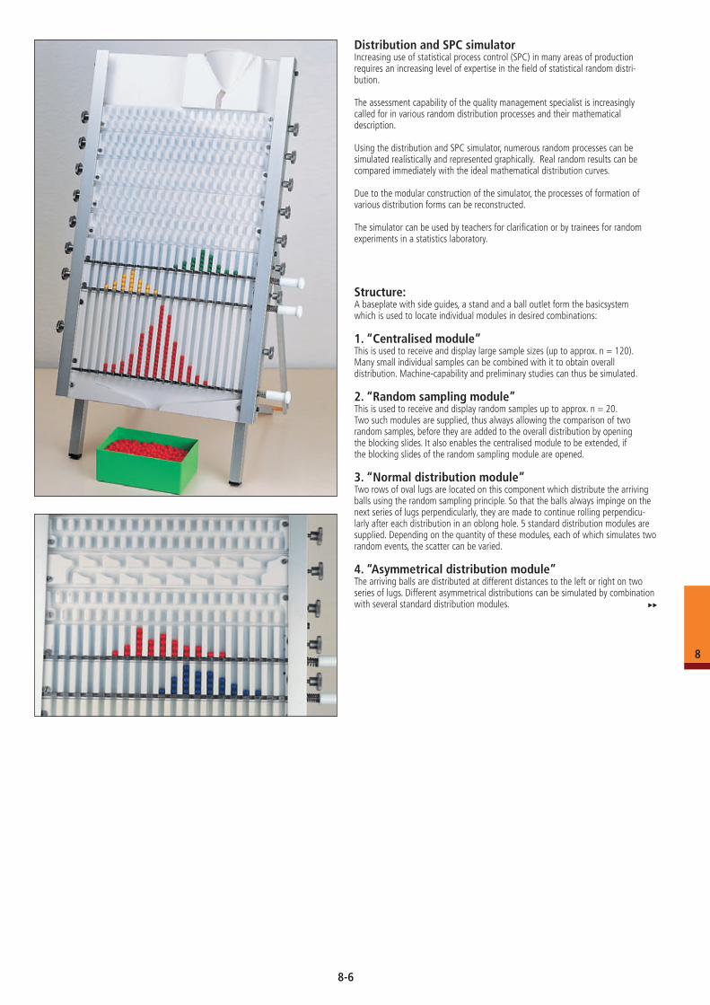
Distribution and SPC simulatorIncreasing use of statistical process control (SPC) in many areas of production requires an increasing level of expertise in the field of statistical random distri- bution.
The assessment capability of the quality management specialist is increasingly called for in various random distribution processes and their mathematical description.
Using the distribution and SPC simulator, numerous random processes can be simulated realistically and represented graphically. Real random results can be compared immediately with the ideal mathematical distribution curves.
Due to the modular construction of the simulator, the processes of formation of various distribution forms can be reconstructed.
The simulator can be used by teachers for clarification or by trainees for random experiments in a statistics laboratory.
Structure:A baseplate with side guides, a stand and a ball outlet form the basicsystem which is used to locate individual modules in desired combinations:
1. “Centralised module”This is used to receive and display large sample sizes (up to approx. n = 120). Many small individual samples can be combined with it to obtain overall distribution. Machine-capability and preliminary studies can thus be simulated.
2. “Random sampling module”This is used to receive and display random samples up to approx. n = 20. Two such modules are supplied, thus always allowing the comparison of two random samples, before they are added to the overall distribution by opening the blocking slides. It also enables the centralised module to be extended, if the blocking slides of the random sampling module are opened.
3. “Normal distribution module”Two rows of oval lugs are located on this component which distribute the arriving balls using the random sampling principle. So that the balls always impinge on the next series of lugs perpendicularly, they are made to continue rolling perpendicu-larly after each distribution in an oblong hole. 5 standard distribution modules are supplied. Depending on the quantity of these modules, each of which simulates two random events, the scatter can be varied.
4. “Asymmetrical distribution module”The arriving balls are distributed at different distances to the left or right on two series of lugs. Different asymmetrical distributions can be simulated by combination with several standard distribution modules.
8
8-6
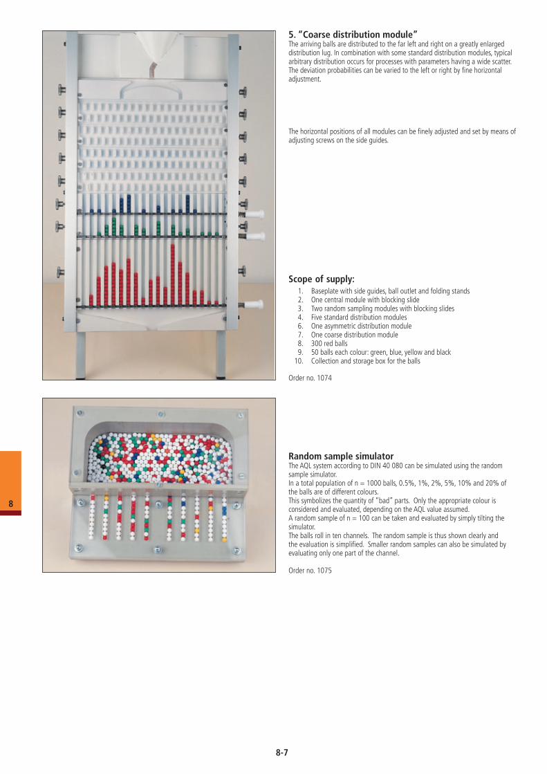
5. “Coarse distribution module”The arriving balls are distributed to the far left and right on a greatly enlarged distribution lug. In combination with some standard distribution modules, typical arbitrary distribution occurs for processes with parameters having a wide scatter. The deviation probabilities can be varied to the left or right by fine horizontal adjustment.
The horizontal positions of all modules can be finely adjusted and set by means of adjusting screws on the side guides.
Scope of supply: 1. Baseplate with side guides, ball outlet and folding stands 2. One central module with blocking slide 3. Two random sampling modules with blocking slides 4. Five standard distribution modules 6. One asymmetric distribution module 7. One coarse distribution module 8. 300 red balls 9. 50 balls each colour: green, blue, yellow and black 10. Collection and storage box for the balls
Order no. 1074
Random sample simulatorThe AQL system according to DIN 40 080 can be simulated using the random sample simulator.In a total population of n = 1000 balls, 0.5%, 1%, 2%, 5%, 10% and 20% of the balls are of different colours.This symbolizes the quantity of “bad” parts. Only the appropriate colour is considered and evaluated, depending on the AQL value assumed.A random sample of n = 100 can be taken and evaluated by simply tilting the simulator.The balls roll in ten channels. The random sample is thus shown clearly and the evaluation is simplified. Smaller random samples can also be simulated by evaluating only one part of the channel.
Order no. 1075
8
8-7
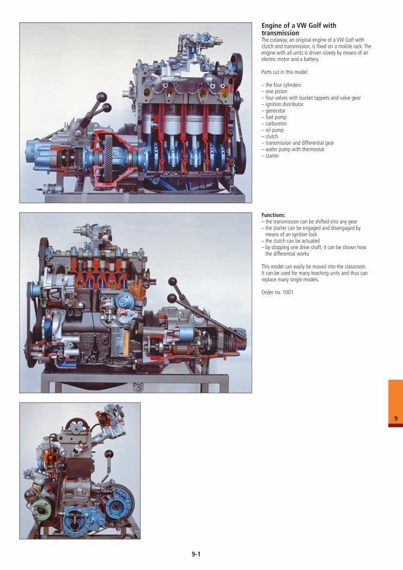
Engine of a VW Golf with transmissionThe cutaway, an original engine of a VW Golf with clutch and transmission, is fixed on a mobile rack. The engine with all units is driven slowly by means of an electric motor and a battery.
Parts cut in this model:
– the four cylinders– one piston– four valves with bucket tappets and valve gear– ignition distributor– generator– fuel pump– carburetor– oil pump– clutch– transmission and differential gear– water pump with thermostat– starter
Functions: – the transmission can be shifted into any gear– the starter can be engaged and disengaged by
means of an ignition lock– the clutch can be actuated– by stopping one drive shaft, it can be shown how
the differential works
This model can easily be moved into the classroom. It can be used for many teaching units and thus can replace many single models.
Order no. 1001
9-1
9
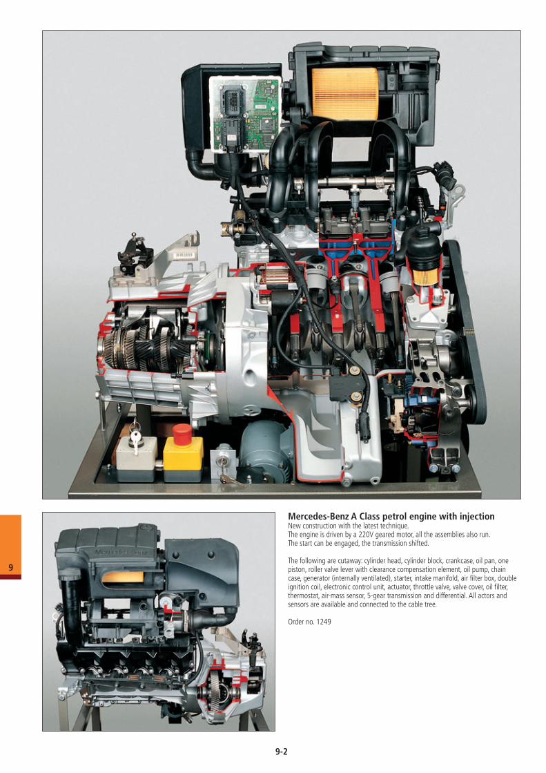
Mercedes-Benz A Class petrol engine with injectionNew construction with the latest technique. The engine is driven by a 220V geared motor, all the assemblies also run. The start can be engaged, the transmission shifted.
The following are cutaway: cylinder head, cylinder block, crankcase, oil pan, one piston, roller valve lever with clearance compensation element, oil pump, chain case, generator (internally ventilated), starter, intake manifold, air filter box, double ignition coil, electronic control unit, actuator, throttle valve, valve cover, oil filter, thermostat, air-mass sensor, 5-gear transmission and differential. All actors and sensors are available and connected to the cable tree.
Order no. 1249
9-2
9
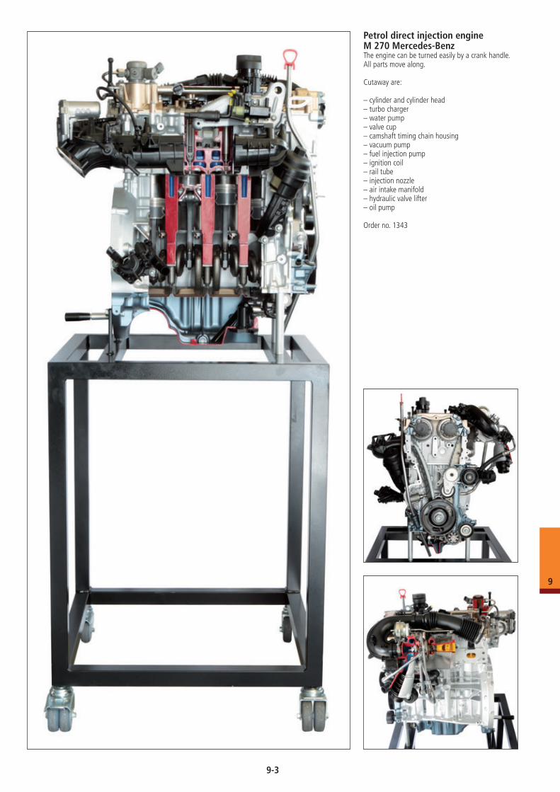
Petrol direct injection engine M 270 Mercedes-BenzThe engine can be turned easily by a crank handle. All parts move along.
Cutaway are:
– cylinder and cylinder head– turbo charger– water pump– valve cup– camshaft timing chain housing– vacuum pump– fuel injection pump– ignition coil– rail tube– injection nozzle– air intake manifold– hydraulic valve lifter– oil pump
Order no. 1343
9-3
9
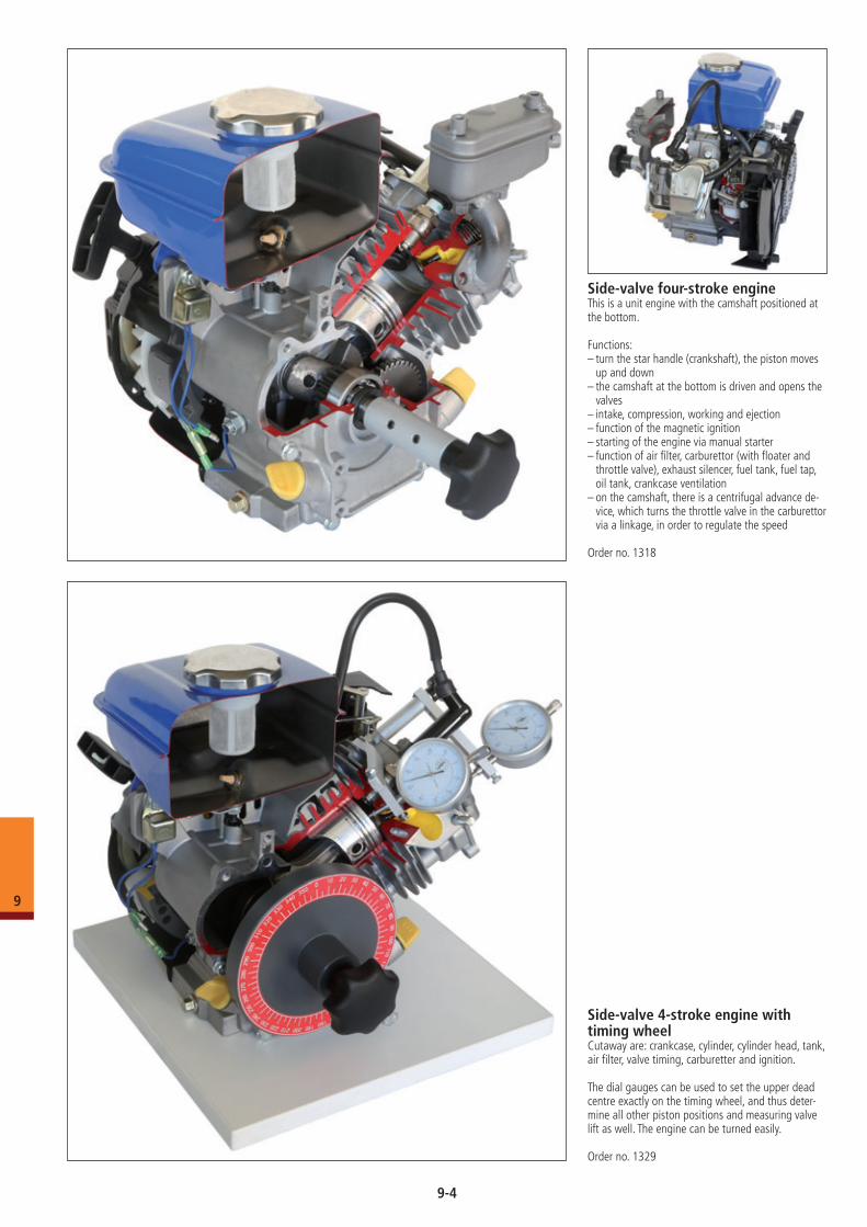
Side-valve four-stroke engineThis is a unit engine with the camshaft positioned at the bottom.
Functions:– turn the star handle (crankshaft), the piston moves
up and down– the camshaft at the bottom is driven and opens the
valves– intake, compression, working and ejection– function of the magnetic ignition– starting of the engine via manual starter– function of air filter, carburettor (with floater and
throttle valve), exhaust silencer, fuel tank, fuel tap, oil tank, crankcase ventilation
– on the camshaft, there is a centrifugal advance de-vice, which turns the throttle valve in the carburettor via a linkage, in order to regulate the speed
Order no. 1318
Side-valve 4-stroke engine with timing wheelCutaway are: crankcase, cylinder, cylinder head, tank, air filter, valve timing, carburetter and ignition.
The dial gauges can be used to set the upper dead centre exactly on the timing wheel, and thus deter-mine all other piston positions and measuring valve lift as well. The engine can be turned easily.
Order no. 1329
9-4
9
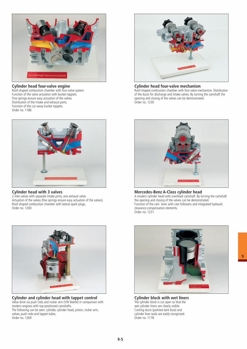
Cylinder head four-valve engineRoof-shaped combustion chamber with four-valve system.Function of the valve actuation with bucket tappets.Fine springs ensure easy actuation of the valves.Distribution of the intake and exhaust ports.Function of the cut-away bucket tappets.Order no. 1186
Cylinder head four-valve mechanismRoof-shaped combustion chamber with four-valve mechanism. Distribution of the ducts for discharge and intake valves. By turning the camshaft the opening and closing of the valves can be demonstrated. Order no. 1230
Mercedes-Benz A-Class cylinder headA modern cylinder head with overhead camshaft. By turning the camshaft the opening and closing of the valves can be demonstrated. Function of the cam lever with cam followers and integrated hydraulic clearance-compensation elements.Order no. 1231
Cylinder head with 3 valves2 inlet valves with separate intake ports, one exhaust valve. Actuation of the valves (fine springs ensure easy actuation of the valves).Roof-shaped combustion chamber with lateral spark plugs.Order no. 1200
Cylinder block with wet linersThe cylinder block is cut open so that the wet cylinder liners are clearly visible.Cooling ducts (painted dark blue) and cylinder liner seals are easily recognised.Order no. 1178
Cylinder and cylinder head with tappet controlValve drive via push rods and rocker arm (VW Beetle) in comparison with modern engines with top-positioned camshafts. The following can be seen: cylinder, cylinder head, piston, rocker arm, valves, push rods and tappet tubes.Order no. 1269
9-5
9
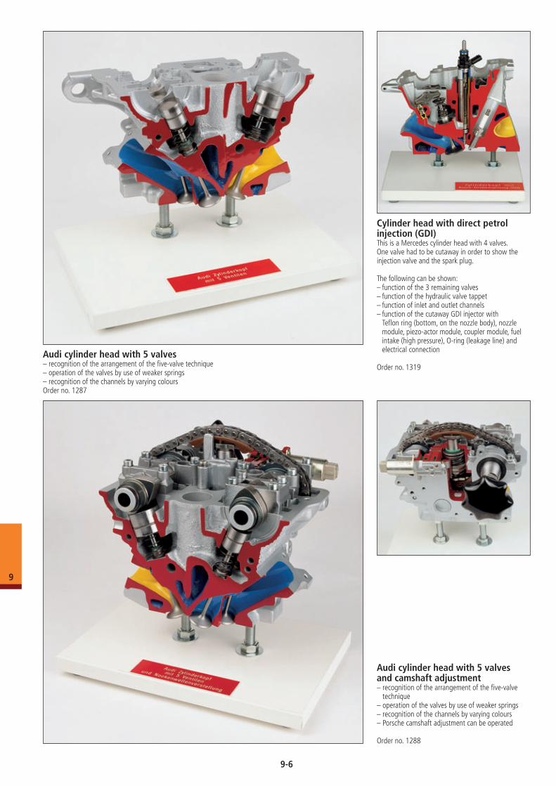
Audi cylinder head with 5 valves– recognition of the arrangement of the five-valve technique– operation of the valves by use of weaker springs– recognition of the channels by varying coloursOrder no. 1287
Audi cylinder head with 5 valves and camshaft adjustment– recognition of the arrangement of the five-valve
technique– operation of the valves by use of weaker springs– recognition of the channels by varying colours– Porsche camshaft adjustment can be operated
Order no. 1288
Cylinder head with direct petrol injection (GDI)This is a Mercedes cylinder head with 4 valves.One valve had to be cutaway in order to show the injection valve and the spark plug.
The following can be shown:– function of the 3 remaining valves– function of the hydraulic valve tappet– function of inlet and outlet channels– function of the cutaway GDI injector with
Teflon ring (bottom, on the nozzle body), nozzle module, piezo-actor module, coupler module, fuel intake (high pressure), O-ring (leakage line) and electrical connection
Order no. 1319
9-6
9
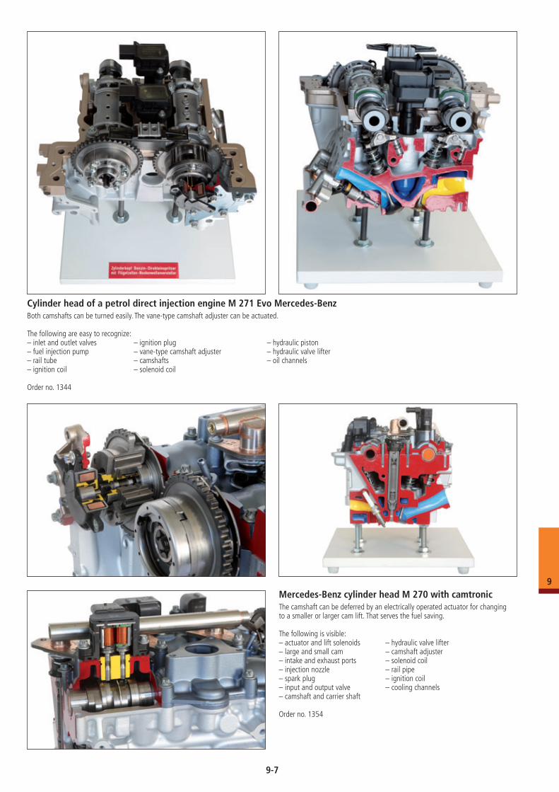
Cylinder head of a petrol direct injection engine M 271 Evo Mercedes-BenzBoth camshafts can be turned easily. The vane-type camshaft adjuster can be actuated.
The following are easy to recognize:– inlet and outlet valves – ignition plug – hydraulic piston– fuel injection pump – vane-type camshaft adjuster – hydraulic valve lifter– rail tube – camshafts – oil channels– ignition coil – solenoid coil
Order no. 1344
Mercedes-Benz cylinder head M 270 with camtronicThe camshaft can be deferred by an electrically operated actuator for changing to a smaller or larger cam lift. That serves the fuel saving.
The following is visible: – actuator and lift solenoids – hydraulic valve lifter– large and small cam – camshaft adjuster– intake and exhaust ports – solenoid coil– injection nozzle – rail pipe– spark plug – ignition coil– input and output valve – cooling channels– camshaft and carrier shaft
Order no. 1354
9-7
9
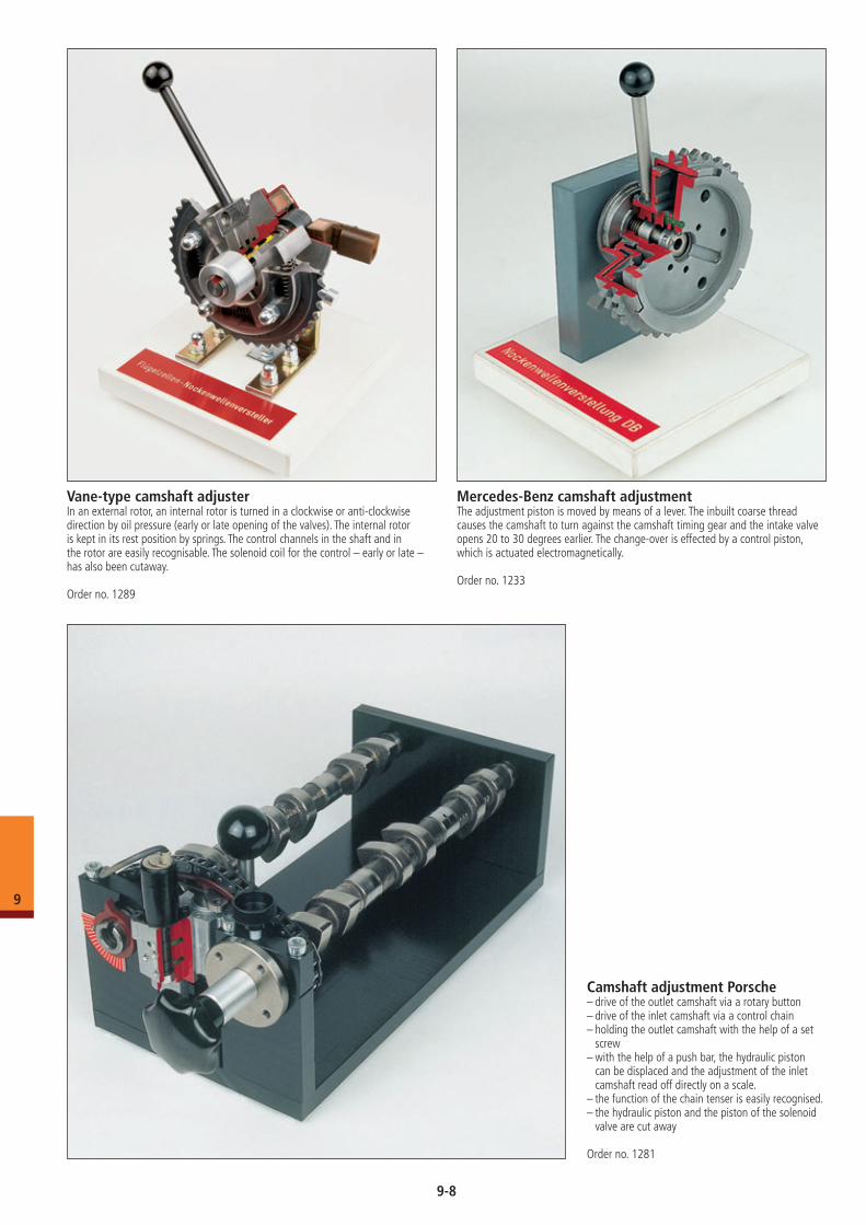
Mercedes-Benz camshaft adjustmentThe adjustment piston is moved by means of a lever. The inbuilt coarse thread causes the camshaft to turn against the camshaft timing gear and the intake valve opens 20 to 30 degrees earlier. The change-over is effected by a control piston, which is actuated electromagnetically.
Order no. 1233
Vane-type camshaft adjusterIn an external rotor, an internal rotor is turned in a clockwise or anti-clockwise direction by oil pressure (early or late opening of the valves). The internal rotor is kept in its rest position by springs. The control channels in the shaft and in the rotor are easily recognisable. The solenoid coil for the control – early or late – has also been cutaway.
Order no. 1289
Camshaft adjustment Porsche– drive of the outlet camshaft via a rotary button– drive of the inlet camshaft via a control chain– holding the outlet camshaft with the help of a set
screw– with the help of a push bar, the hydraulic piston
can be displaced and the adjustment of the inlet camshaft read off directly on a scale.
– the function of the chain tenser is easily recognised.– the hydraulic piston and the piston of the solenoid
valve are cut away
Order no. 1281
9-8
9
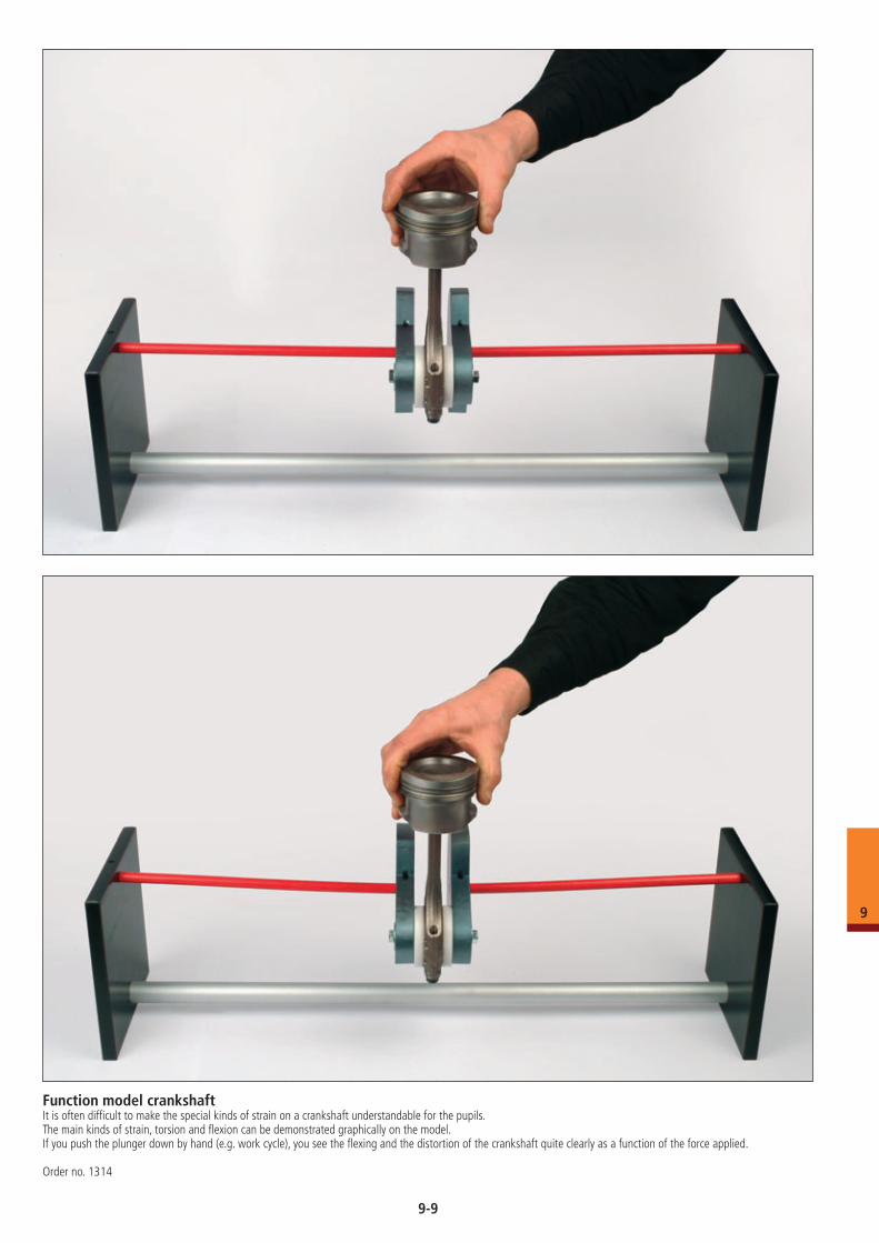
Function model crankshaftIt is often difficult to make the special kinds of strain on a crankshaft understandable for the pupils. The main kinds of strain, torsion and flexion can be demonstrated graphically on the model. If you push the plunger down by hand (e.g. work cycle), you see the flexing and the distortion of the crankshaft quite clearly as a function of the force applied.
Order no. 1314
9-9
9
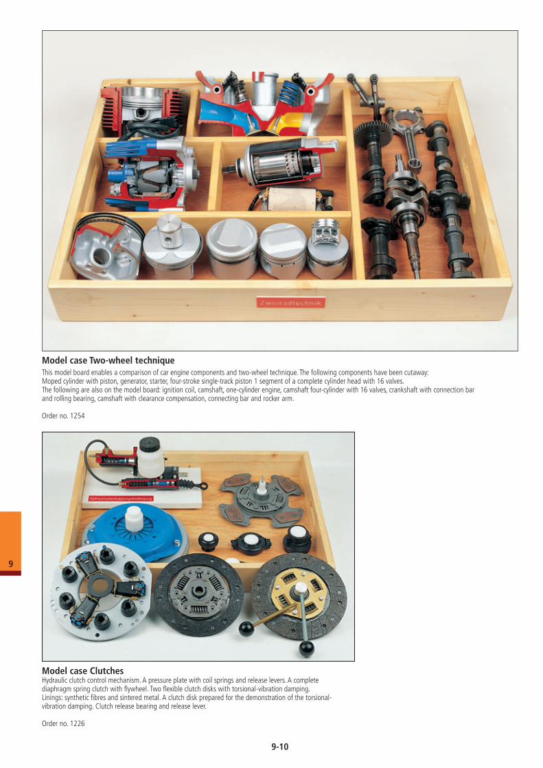
Model case Two-wheel techniqueThis model board enables a comparison of car engine components and two-wheel technique. The following components have been cutaway:Moped cylinder with piston, generator, starter, four-stroke single-track piston 1 segment of a complete cylinder head with 16 valves.The following are also on the model board: ignition coil, camshaft, one-cylinder engine, camshaft four-cylinder with 16 valves, crankshaft with connection bar and rolling bearing, camshaft with clearance compensation, connecting bar and rocker arm.
Order no. 1254
Model case ClutchesHydraulic clutch control mechanism. A pressure plate with coil springs and release levers. A complete diaphragm spring clutch with flywheel. Two flexible clutch disks with torsional-vibration damping. Linings: synthetic fibres and sintered metal. A clutch disk prepared for the demonstration of the torsional- vibration damping. Clutch release bearing and release lever.
Order no. 1226
9-10
9
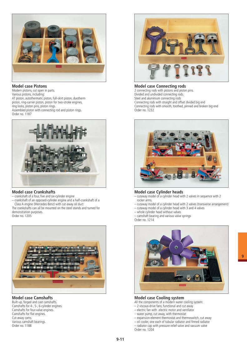
Model case Crankshafts– crankshaft of a four, five and six-cylinder engine– crankshaft of an opposed-cylinder engine and a half-crankshaft of a
Class A engine (Mercedes-Benz) with cut-away oil ductThe crankshafts can all be mounted on the steel stands and turned for demonstration purposes.Order no. 1205
Model case CamshaftsBuilt-up, forged and cast camshafts.Camshafts for 4-, 5-, 6-cylinder engines.Camshafts for four-valve engines.Camshafts for flat engines.Cut-away cams.Various camshaft bearings.Order no. 1188
Model case Cylinder heads– cutaway model of a cylinder head with 2 valves in sequence with 2
rocker arms. – cutaway model of a cylinder head with 2 valves (transverse arrangement)– cutaway model of a cylinder head with 3 and 4 valves– whole cylinder head without valves– camshaft bearing and various valve springsOrder no. 1214
Model case PistonsModern pistons, cut open in parts.Various pistons, including:AT piston, autothermatic piston, full-skirt piston, duotherm piston, ring-carrier piston, piston for two-stroke engines,ring locks, piston pins, piston rings.Assembled piston with connecting rod and piston rings.Order no. 1187
Model case Connecting rods2 connecting rods with pistons and piston pins.Divided and undivided connecting rods.Steel and aluminium connecting rodsConnecting rods with straight and offset divided big end Connecting rods with smooth, toothed, pinned and broken big end Order no. 1232
Model case Cooling systemAll the components of a modern water cooling system:– 2 viscous-drive fans, functional and cut away– electric fan with electric motor and ventilator– water pump, cut away, with thermostat– expansion-element thermostat and thermoswitch, cut away– oil cooler, one each of tubular radiator and finned radiator– radiator cap with pressure relief valve and vacuum valveOrder no. 1204
9-11
9
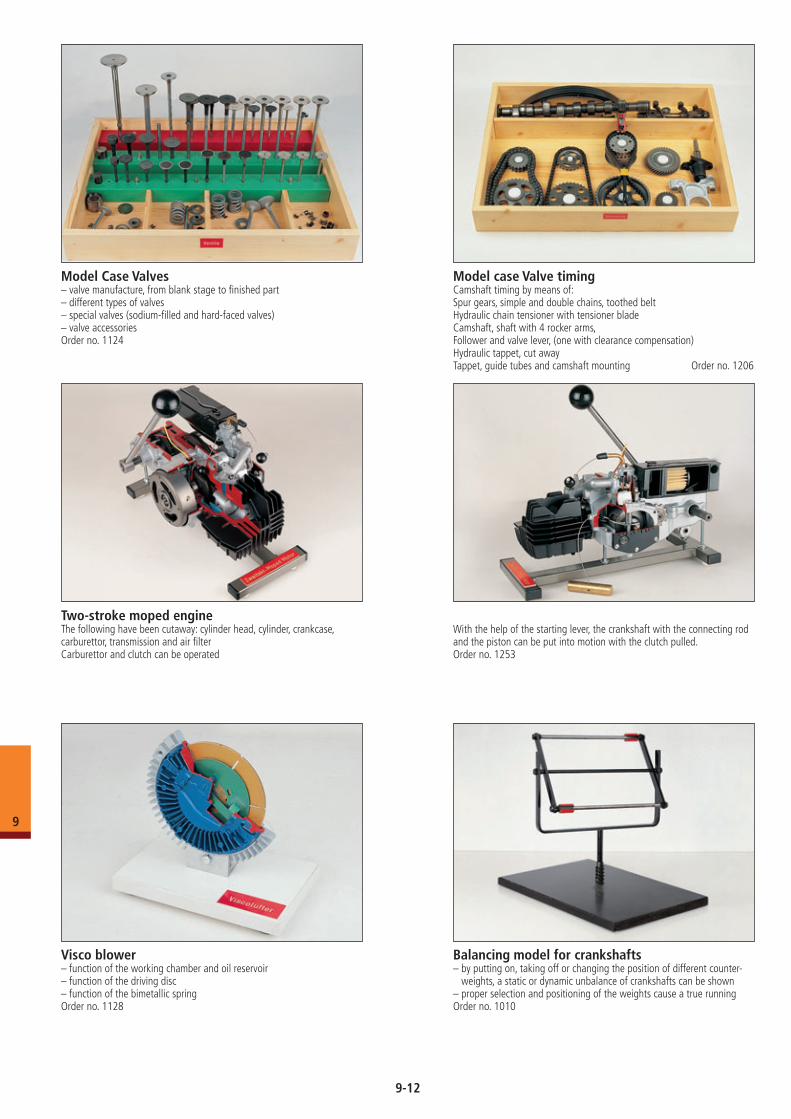
Visco blower– function of the working chamber and oil reservoir– function of the driving disc– function of the bimetallic springOrder no. 1128
Two-stroke moped engineThe following have been cutaway: cylinder head, cylinder, crankcase, carburettor, transmission and air filterCarburettor and clutch can be operated
With the help of the starting lever, the crankshaft with the connecting rod and the piston can be put into motion with the clutch pulled.Order no. 1253
Balancing model for crankshafts– by putting on, taking off or changing the position of different counter-
weights, a static or dynamic unbalance of crankshafts can be shown– proper selection and positioning of the weights cause a true running Order no. 1010
Model Case Valves– valve manufacture, from blank stage to finished part– different types of valves– special valves (sodium-filled and hard-faced valves)– valve accessoriesOrder no. 1124
Model case Valve timingCamshaft timing by means of:Spur gears, simple and double chains, toothed beltHydraulic chain tensioner with tensioner bladeCamshaft, shaft with 4 rocker arms, Follower and valve lever, (one with clearance compensation)Hydraulic tappet, cut awayTappet, guide tubes and camshaft mounting Order no. 1206
9-12
9
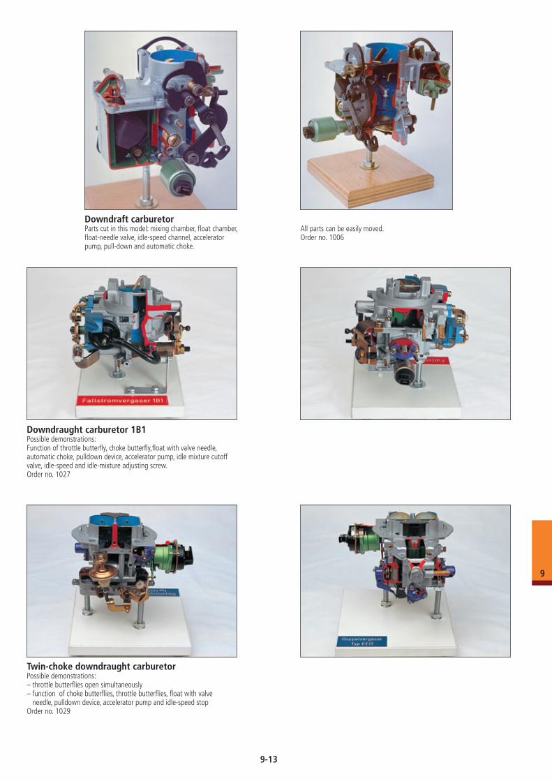
Downdraft carburetor Parts cut in this model: mixing chamber, float chamber, float-needle valve, idle-speed channel, accelerator pump, pull-down and automatic choke.
All parts can be easily moved.Order no. 1006
Downdraught carburetor 1B1Possible demonstrations:Function of throttle butterfly, choke butterfly,float with valve needle, automatic choke, pulldown device, accelerator pump, idle mixture cutoff valve, idle-speed and idle-mixture adjusting screw.Order no. 1027
Twin-choke downdraught carburetorPossible demonstrations: – throttle butterflies open simultaneously– function of choke butterflies, throttle butterflies, float with valve
needle, pulldown device, accelerator pump and idle-speed stopOrder no. 1029
9-13
9
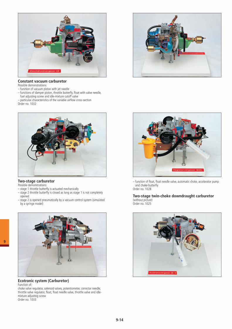
Constant vacuum carburetorPossible demonstrations:– function of vacuum piston with jet needle – functions of damper piston, throttle butterfly, float with valve needle,
fuel adjusting screw and idle-mixture cutoff valve– particular characteristics of the variable airflow cross-sectionOrder no. 1032
Ecotronic system (Carburetor)Function of:choke valve regulator, solenoid valves, potentiometer, corrector needle, throttle valve regulator, float, float needle valve, throttle valve and idle-mixture adjusting screwOrder no. 1033
Two-stage carburetorPossible demonstrations: – stage 1 throttle butterfly is actuated mechanically– stage 2 throttle butterfly is closed as long as stage 1 is not completely
opened– stage 2 is opened pneumatically by a vacuum control system (simulated
by a syringe model)
– function of float, float needle valve, automatic choke, accelerator pump and choke-butterfly
Order no. 1028
Two-stage twin-choke downdraught carburetor(without picture)Order no. 1025
9-14
9
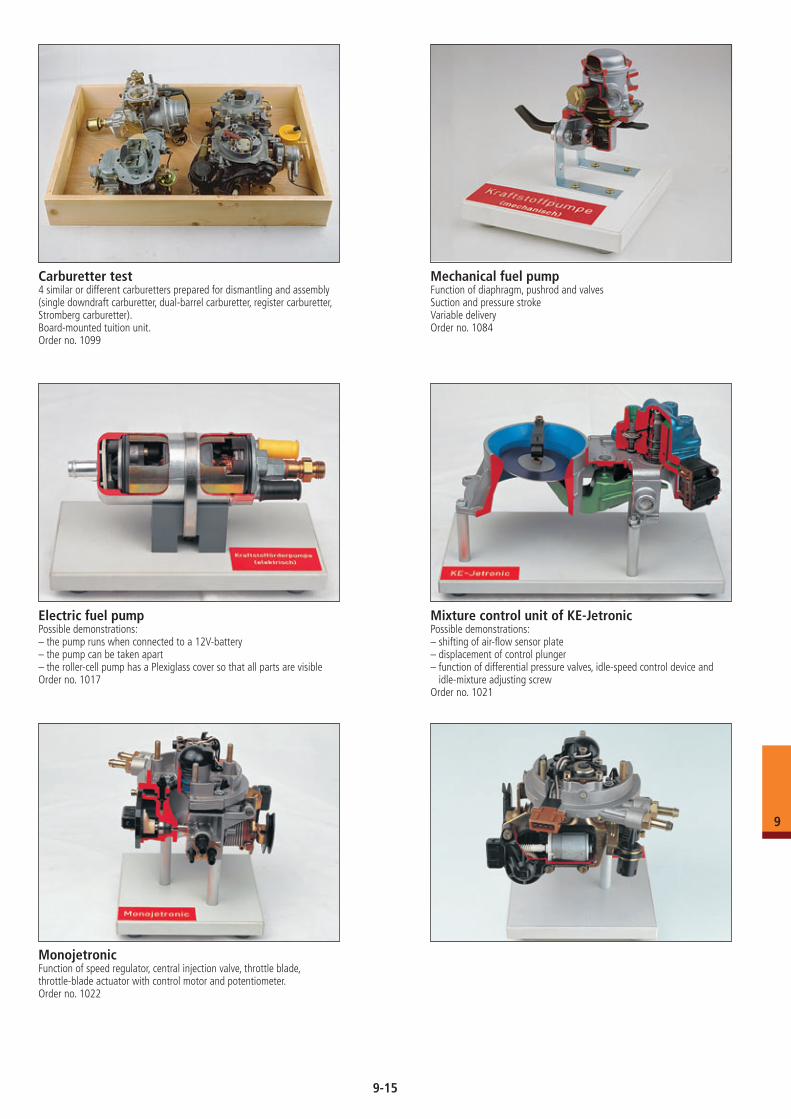
Carburetter test4 similar or different carburetters prepared for dismantling and assembly(single downdraft carburetter, dual-barrel carburetter, register carburetter, Stromberg carburetter).Board-mounted tuition unit.Order no. 1099
Mechanical fuel pumpFunction of diaphragm, pushrod and valvesSuction and pressure strokeVariable deliveryOrder no. 1084
MonojetronicFunction of speed regulator, central injection valve, throttle blade,throttle-blade actuator with control motor and potentiometer.Order no. 1022
Electric fuel pumpPossible demonstrations: – the pump runs when connected to a 12V-battery– the pump can be taken apart– the roller-cell pump has a Plexiglass cover so that all parts are visibleOrder no. 1017
Mixture control unit of KE-JetronicPossible demonstrations:– shifting of air-flow sensor plate– displacement of control plunger– function of differential pressure valves, idle-speed control device and
idle-mixture adjusting screwOrder no. 1021
9-15
9
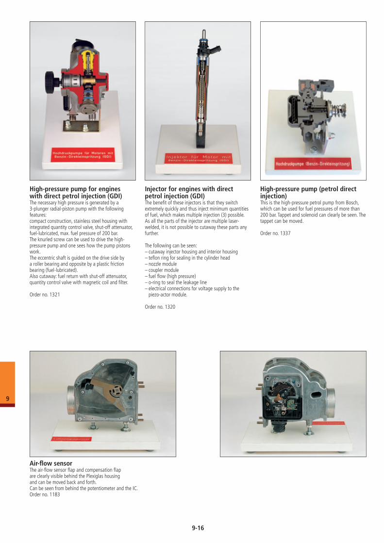
High-pressure pump for engines with direct petrol injection (GDI)The necessary high pressure is generated by a 3-plunger radial-piston pump with the following features: compact construction, stainless steel housing with integrated quantity control valve, shut-off attenuator, fuel-lubricated, max. fuel pressure of 200 bar.The knurled screw can be used to drive the high-pressure pump and one sees how the pump pistons work.The eccentric shaft is guided on the drive side by a roller bearing and opposite by a plastic friction bearing (fuel-lubricated).Also cutaway: fuel return with shut-off attenuator, quantity control valve with magnetic coil and filter.
Order no. 1321
Injector for engines with direct petrol injection (GDI)The benefit of these injectors is that they switch extremely quickly and thus inject minimum quantities of fuel, which makes multiple injection (3) possible.As all the parts of the injector are multiple laser-welded, it is not possible to cutaway these parts any further.
The following can be seen:– cutaway injector housing and interior housing– teflon ring for sealing in the cylinder head– nozzle module– coupler module– fuel flow (high pressure)– o-ring to seal the leakage line– electrical connections for voltage supply to the
piezo-actor module.
Order no. 1320
High-pressure pump (petrol direct injection)This is the high-pressure petrol pump from Bosch, which can be used for fuel pressures of more than 200 bar. Tappet and solenoid can clearly be seen. The tappet can be moved.
Order no. 1337
Air-flow sensorThe air-flow sensor flap and compensation flapare clearly visible behind the Plexiglas housingand can be moved back and forth.Can be seen from behind the potentiometer and the IC.Order no. 1183
9-16
9
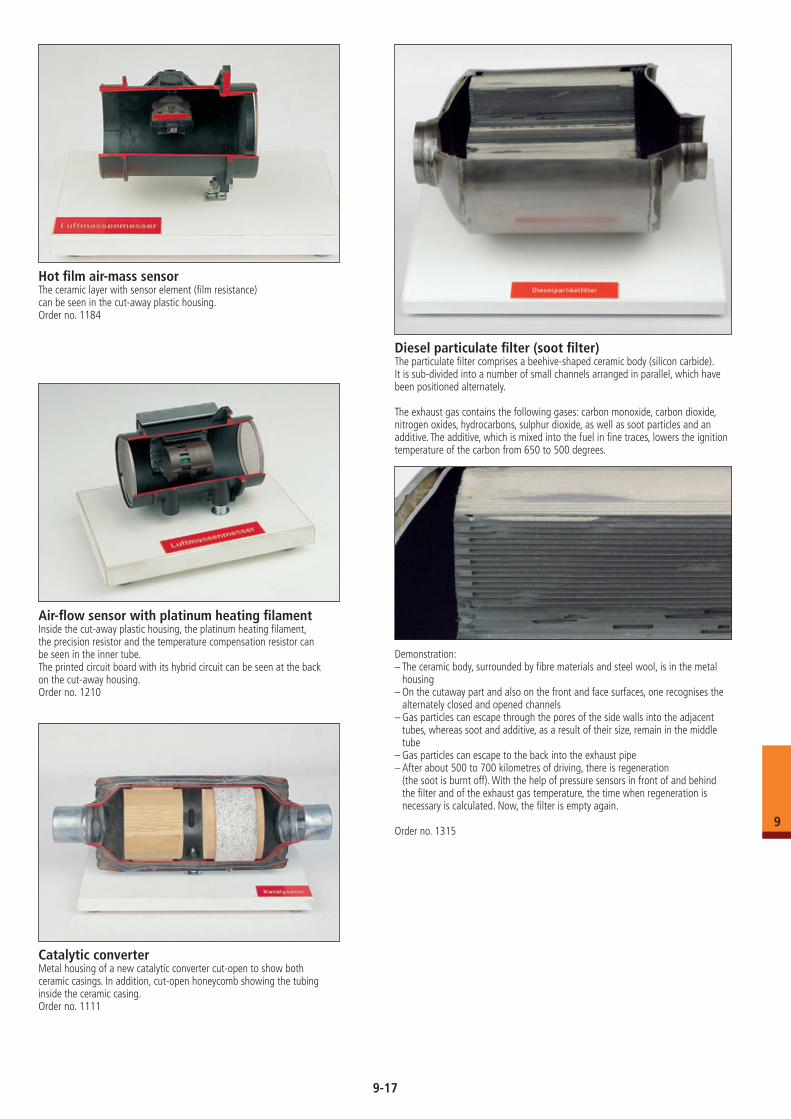
Hot film air-mass sensorThe ceramic layer with sensor element (film resistance) can be seen in the cut-away plastic housing.Order no. 1184
Air-flow sensor with platinum heating filamentInside the cut-away plastic housing, the platinum heating filament, the precision resistor and the temperature compensation resistor can be seen in the inner tube.The printed circuit board with its hybrid circuit can be seen at the back on the cut-away housing. Order no. 1210
Catalytic converterMetal housing of a new catalytic converter cut-open to show both ceramic casings. In addition, cut-open honeycomb showing the tubing inside the ceramic casing.Order no. 1111
Diesel particulate filter (soot filter)The particulate filter comprises a beehive-shaped ceramic body (silicon carbide).It is sub-divided into a number of small channels arranged in parallel, which have been positioned alternately.
The exhaust gas contains the following gases: carbon monoxide, carbon dioxide, nitrogen oxides, hydrocarbons, sulphur dioxide, as well as soot particles and an additive. The additive, which is mixed into the fuel in fine traces, lowers the ignition temperature of the carbon from 650 to 500 degrees.
Demonstration:– The ceramic body, surrounded by fibre materials and steel wool, is in the metal
housing– On the cutaway part and also on the front and face surfaces, one recognises the
alternately closed and opened channels– Gas particles can escape through the pores of the side walls into the adjacent
tubes, whereas soot and additive, as a result of their size, remain in the middle tube
– Gas particles can escape to the back into the exhaust pipe– After about 500 to 700 kilometres of driving, there is regeneration
(the soot is burnt off). With the help of pressure sensors in front of and behind the filter and of the exhaust gas temperature, the time when regeneration is necessary is calculated. Now, the filter is empty again.
Order no. 1315
9-17
9
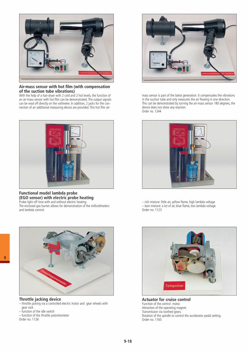
Air-mass sensor with hot film (with compensation of the suction tube vibrations)With the help of a hair-dryer with 2 cold and 2 hot levels, the function of an air-mass sensor with hot film can be demonstrated. The output signals can be read off directly on the voltmeter. In addition, 2 jacks for the con-nection of an additional measuring device are provided. This hot film air-
mass sensor is part of the latest generation. It compensates the vibrations in the suction tube and only measures the air flowing in one direction. This can be demonstrated by turning the air-mass sensor 180 degrees, the device does not show any reaction.Order no. 1244
Functional model lambda probe (EGO sensor) with electric probe heatingProbe light-off time with and without electric heating.The enclosed gas burner allows for demonstration of the millivoltmeters and lambda control:
– rich mixture: little air, yellow flame, high lambda voltage– lean mixture: a lot of air, blue flame, low lambda voltageOrder no. 1123
Throttle jacking device– throttle jacking via a controlled electric motor and gear wheels with
gear rack– function of the idle switch– function of the throttle potentiometerOrder no. 1126
Actuator for cruise controlFunction of the control motor.Attraction of the operating magnet.Transmission via toothed gears.Rotation of the spindle to control the accelerator pedal setting.Order no. 1165
9-18
9
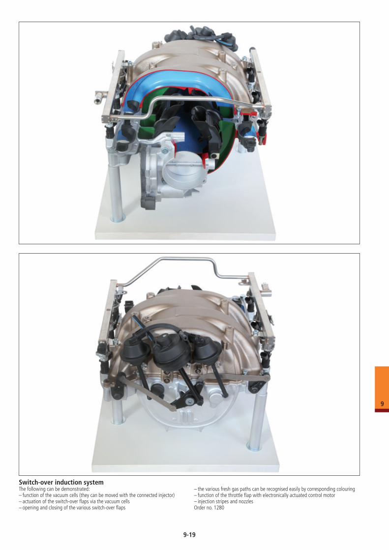
Switch-over induction systemThe following can be demonstrated:– function of the vacuum cells (they can be moved with the connected injector)– actuation of the switch-over flaps via the vacuum cells– opening and closing of the various switch-over flaps
– the various fresh gas paths can be recognised easily by corresponding colouring– function of the throttle flap with electronically actuated control motor– injection stripes and nozzlesOrder no. 1280
9-19
9
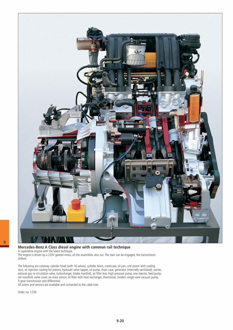
Mercedes-Benz A Class diesel engine with common rail techniqueA superlative engine with the latest technique. The engine is driven by a 220V geared motor, all the assemblies also run. The start can be engaged, the transmission shifted.
The following are cutaway: cylinder head (with 16 valves), cylinder block, crankcase, oil pan, one piston with cooling duct, oil injection cooling for pistons, hydraulic valve tappet, oil pump, chain case, generator (internally ventilated), starter, exhaust gas re-circulation valve, turbocharger, intake manifold, air filter box, high-pressure pump, one injector, feed pump, rail manifold, valve cover, air-mass sensor, oil filter with heat exchanger, thermostat, modern single-vane vacuum pump, 5-gear transmission and differential. All actors and sensors are available and connected to the cable tree.
Order no. 1250
9-20
9
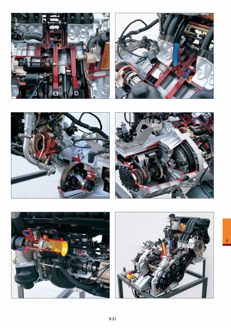
9-21
9
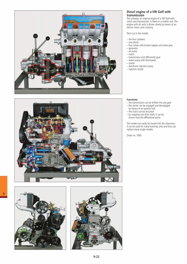
Diesel engine of a VW Golf with transmissionThe cutaway, an original engine of a VW Golf with clutch and transmission, is fixed on a mobile rack. The engine with all units is driven slowly by means of an electric motor and a battery.
Parts cut in this model: – the four cylinders– one piston– four valves with bucket tappets and valve gear– generator– oil pump– clutch– transmission and differential gear– water pump with thermostat– starter– distributor injection pump– injection nozzle
Functions: – the transmission can be shifted into any gear– the starter can be engaged and disengaged
by means of an ignition lock– the clutch can be actuated– by stopping one drive shaft, it can be
shown how the differential works
This model can easily be moved into the classroom. It can be used for many teaching units and thus can replace many single models
Order no. 1065
9-22
9
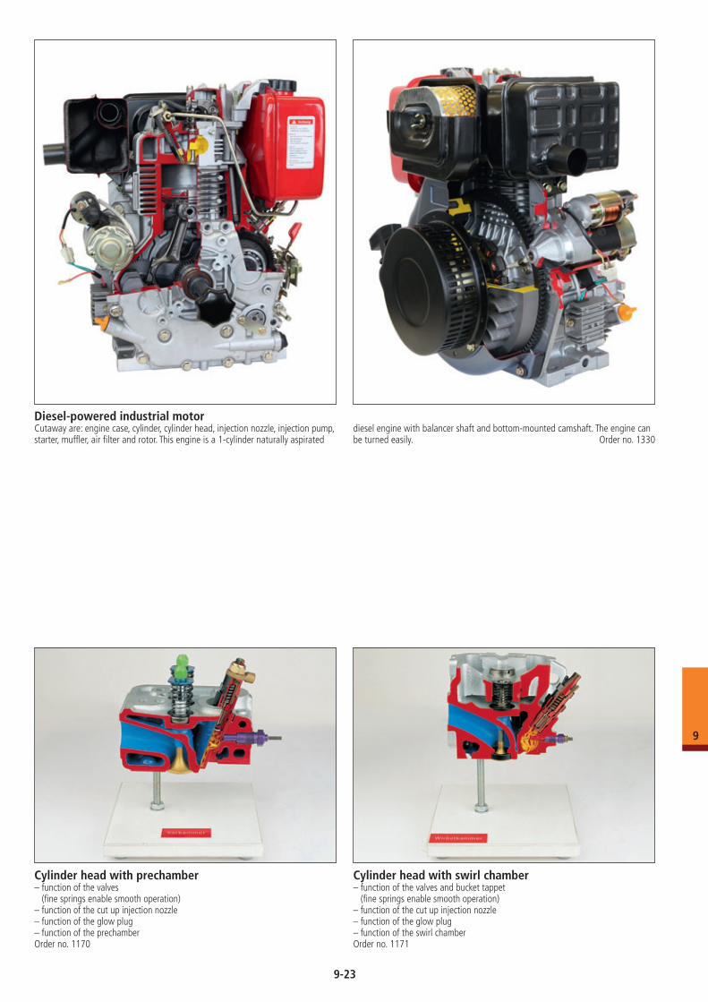
Diesel-powered industrial motorCutaway are: engine case, cylinder, cylinder head, injection nozzle, injection pump, starter, muffler, air filter and rotor. This engine is a 1-cylinder naturally aspirated
diesel engine with balancer shaft and bottom-mounted camshaft. The engine can be turned easily. Order no. 1330
Cylinder head with prechamber– function of the valves
(fine springs enable smooth operation)– function of the cut up injection nozzle– function of the glow plug– function of the prechamberOrder no. 1170
Cylinder head with swirl chamber– function of the valves and bucket tappet
(fine springs enable smooth operation)– function of the cut up injection nozzle– function of the glow plug– function of the swirl chamberOrder no. 1171
9-23
9
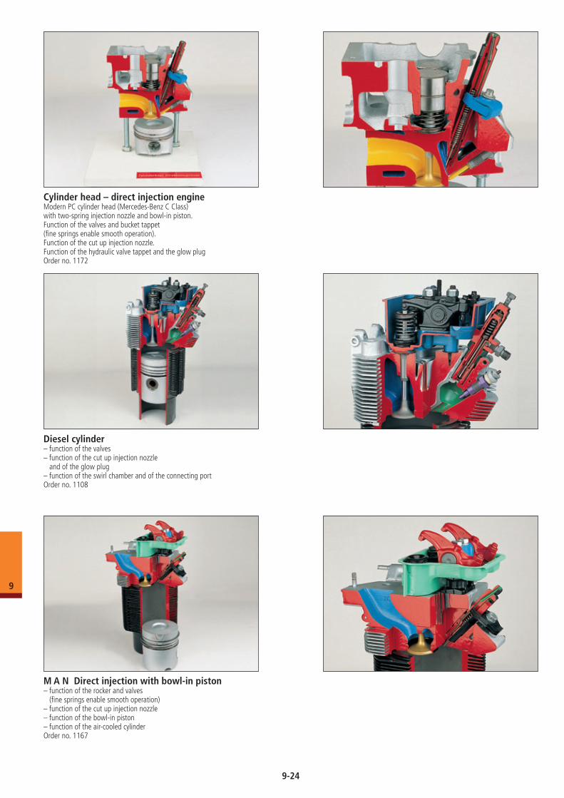
M A N Direct injection with bowl-in piston– function of the rocker and valves
(fine springs enable smooth operation)– function of the cut up injection nozzle– function of the bowl-in piston– function of the air-cooled cylinderOrder no. 1167
Cylinder head – direct injection engineModern PC cylinder head (Mercedes-Benz C Class)with two-spring injection nozzle and bowl-in piston.Function of the valves and bucket tappet(fine springs enable smooth operation).Function of the cut up injection nozzle.Function of the hydraulic valve tappet and the glow plugOrder no. 1172
Diesel cylinder– function of the valves– function of the cut up injection nozzle
and of the glow plug– function of the swirl chamber and of the connecting portOrder no. 1108
9-24
9
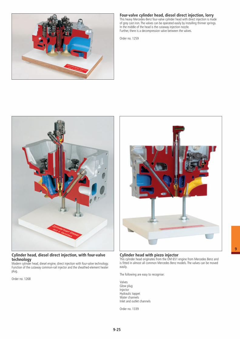
Four-valve cylinder head, diesel direct injection, lorryThis heavy Mercedes-Benz four-valve cylinder head with direct injection is made of grey cast iron. The valves can be operated easily by installing thinner springs. In the middle of the head is the cutaway injection nozzle.Further, there is a decompression valve between the valves.
Order no. 1259
Cylinder head, diesel direct injection, with four-valve technologyModern cylinder head, diesel engine, direct injection with four-valve technology. Function of the cutaway common-rail injector and the sheathed-element heater plug.
Order no. 1268
Cylinder head with piezo injectorThis cylinder head originates from the OM 651 engine from Mercedes Benz and is fitted in almost all common Mercedes Benz models. The valves can be moved easily.
The following are easy to recognise:
ValvesGlow plugInjectorHydraulic tappetWater channelsInlet and outlet channels
Order no. 1339
9-25
9
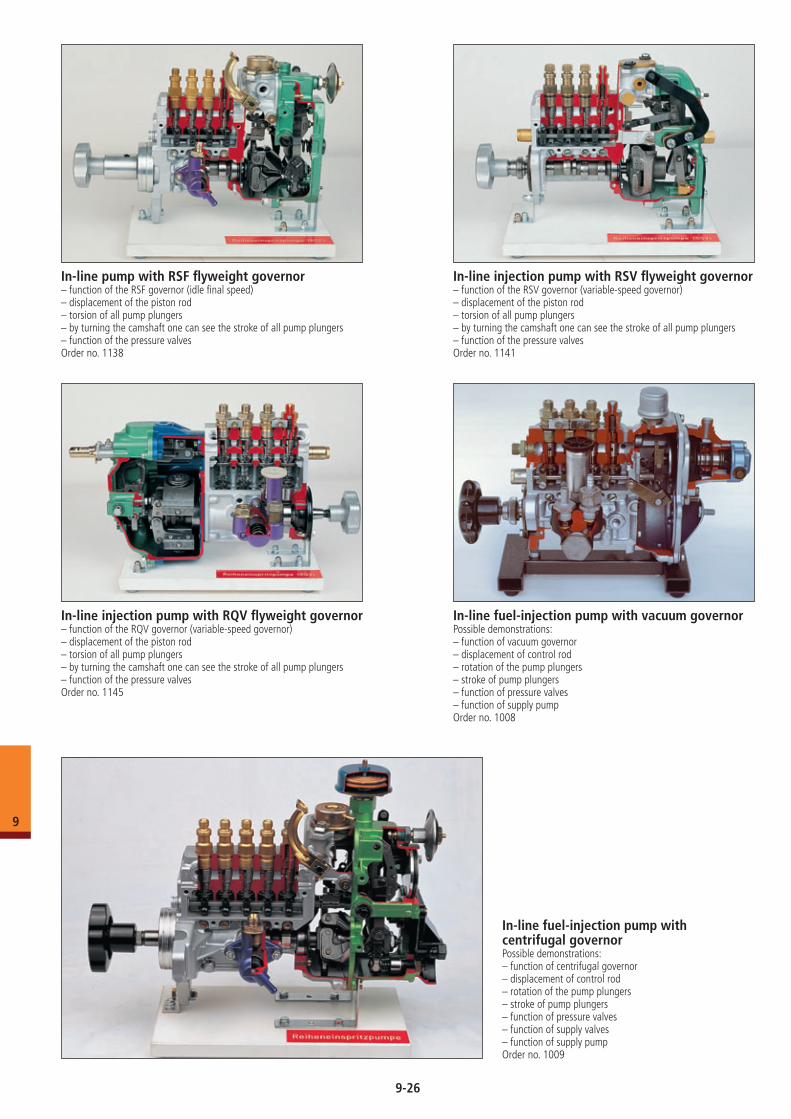
In-line pump with RSF flyweight governor– function of the RSF governor (idle final speed)– displacement of the piston rod– torsion of all pump plungers– by turning the camshaft one can see the stroke of all pump plungers– function of the pressure valvesOrder no. 1138
In-line injection pump with RSV flyweight governor– function of the RSV governor (variable-speed governor)– displacement of the piston rod– torsion of all pump plungers– by turning the camshaft one can see the stroke of all pump plungers– function of the pressure valvesOrder no. 1141
In-line injection pump with RQV flyweight governor– function of the RQV governor (variable-speed governor)– displacement of the piston rod– torsion of all pump plungers– by turning the camshaft one can see the stroke of all pump plungers– function of the pressure valvesOrder no. 1145
In-line fuel-injection pump with vacuum governorPossible demonstrations:– function of vacuum governor– displacement of control rod– rotation of the pump plungers– stroke of pump plungers– function of pressure valves– function of supply pumpOrder no. 1008
In-line fuel-injection pump with centrifugal governorPossible demonstrations:– function of centrifugal governor– displacement of control rod– rotation of the pump plungers– stroke of pump plungers– function of pressure valves– function of supply valves– function of supply pumpOrder no. 1009
9-26
9
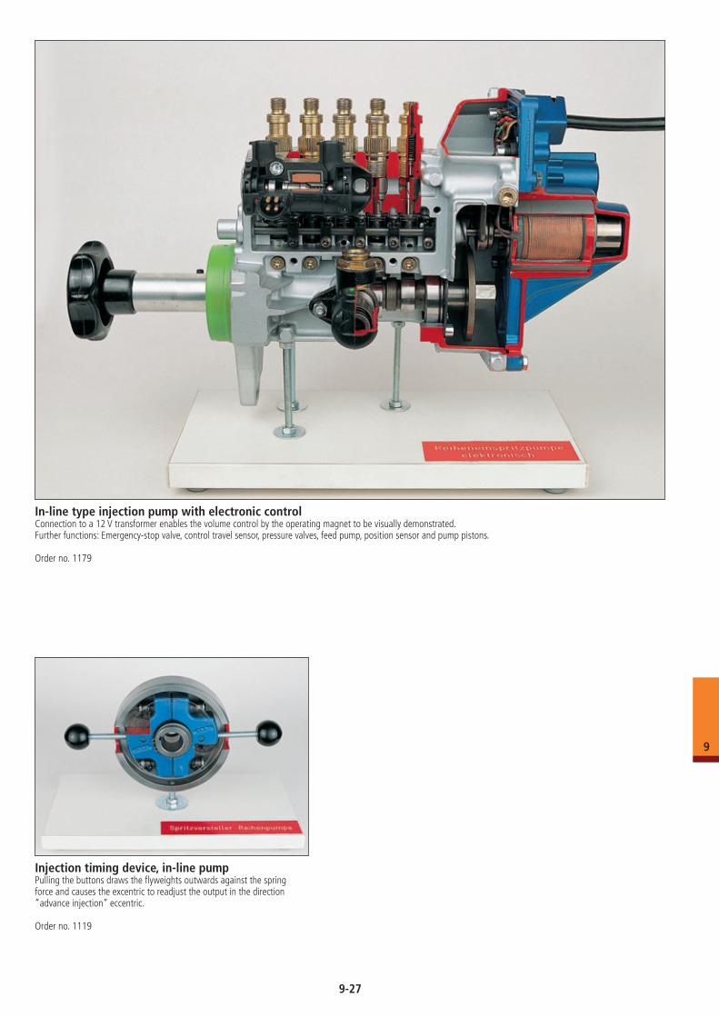
In-line type injection pump with electronic controlConnection to a 12 V transformer enables the volume control by the operating magnet to be visually demonstrated.Further functions: Emergency-stop valve, control travel sensor, pressure valves, feed pump, position sensor and pump pistons.
Order no. 1179
Injection timing device, in-line pumpPulling the buttons draws the flyweights outwards against the spring force and causes the excentric to readjust the output in the direction ”advance injection” eccentric.
Order no. 1119
9-27
9
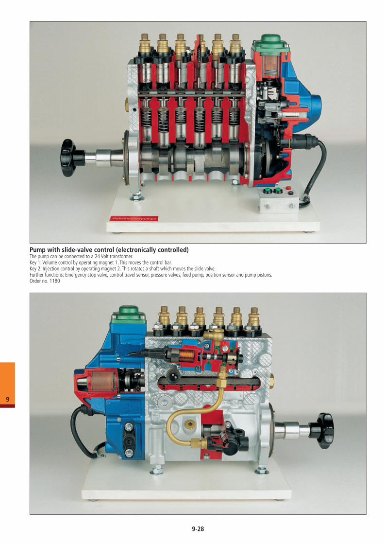
Pump with slide-valve control (electronically controlled)The pump can be connected to a 24 Volt transformer.Key 1: Volume control by operating magnet 1. This moves the control bar.Key 2: Injection control by operating magnet 2. This rotates a shaft which moves the slide valve.Further functions: Emergency-stop valve, control travel sensor, pressure valves, feed pump, position sensor and pump pistons.Order no. 1180
9-28
9
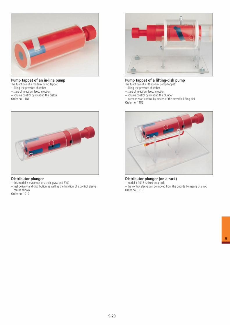
Pump tappet of an in-line pumpThe functions of a modern pump tappet:– filling the pressure chamber– start of injection, feed, injection– volume control by rotating the pistonOrder no. 1181
Pump tappet of a lifting-disk pumpThe functions of a lifting-disk pump tappet:– filling the pressure chamber– start of injection, feed, injection– volume control by rotating the plunger– injection start control by means of the movable lifting diskOrder no. 1182
Distributor plunger– this model is made out of acrylic glass and PVC– fuel delivery and distribution as well as the function of a control sleeve
can be shownOrder no. 1012
Distributor plunger (on a rack)– model # 1012 is fixed on a rack– the control sleeve can be moved from the outside by means of a rodOrder no. 1013
9-29
9
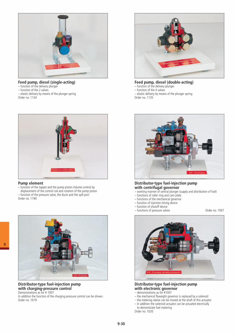
Pump element– function of the tappet and the pump piston.Volume control by
displacement of the control rod and rotation of the pump piston– function of the pressure valve, the ducts and the spill portOrder no. 1190
Distributor-type fuel-injection pump with charging-pressure controlDemonstrations as for # 1007In addition the function of the charging-pressure control can be shown.Order no. 1019
Distributor-type fuel-injection pump with centrifugal governor– working manner of central plunger (supply and distribution of fuel)– functions of roller ring and cam plate– functions of the mechanical governor– function of injection timing device– function of shutoff device– functions of pressure valves Order no. 1007
Distributor-type fuel-injection pump with electronic governor– demonstrations as for #1007– the mechanical flyweight governor is replaced by a solenoid– the metering sleeve can be moved at the shaft of this actuator – in addition the solenoid actuator can be actuated electrically to demonstrate fuel meteringOrder no. 1020
Feed pump, diesel (single-acting)– function of the delivery plunger– function of the 2 valves– elastic delivery by means of the plunger springOrder no. 1134
Feed pump, diesel (double-acting)– function of the delivery plunger– function of the 4 valves– elastic delivery by means of the plunger springOrder no. 1135
9-30
9
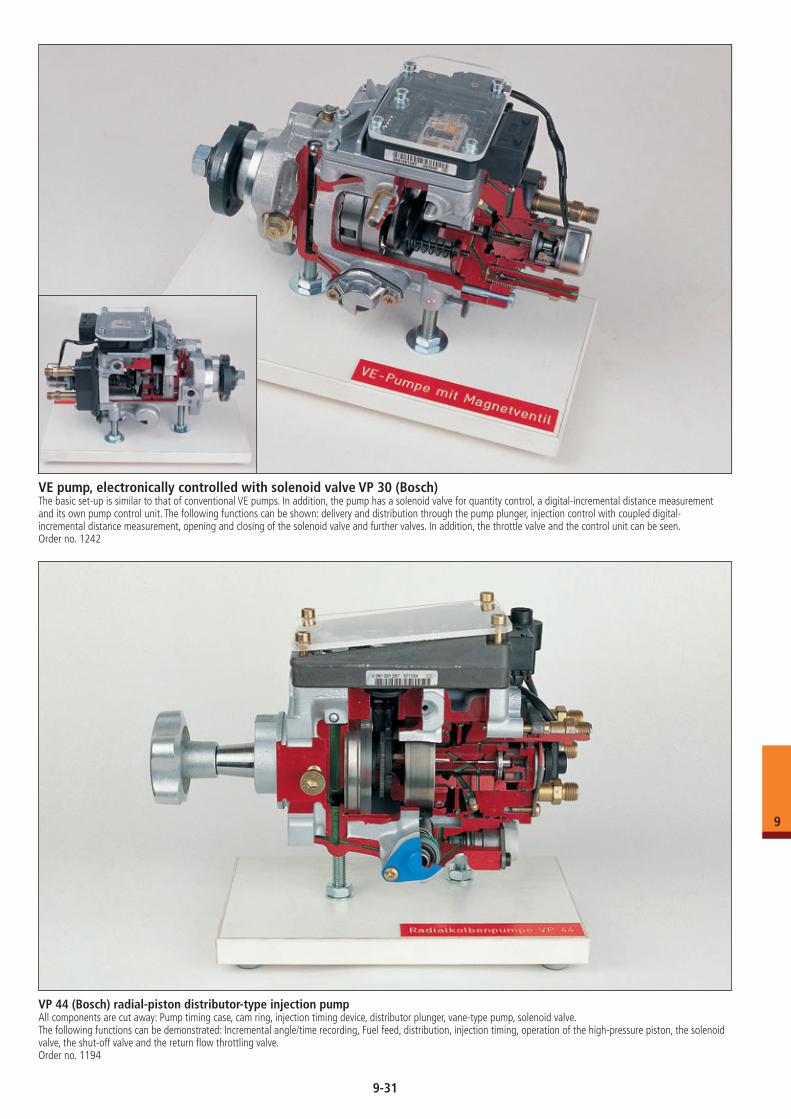
VE pump, electronically controlled with solenoid valve VP 30 (Bosch)The basic set-up is similar to that of conventional VE pumps. In addition, the pump has a solenoid valve for quantity control, a digital-incremental distance measurement and its own pump control unit. The following functions can be shown: delivery and distribution through the pump plunger, injection control with coupled digital- incremental distance measurement, opening and closing of the solenoid valve and further valves. In addition, the throttle valve and the control unit can be seen.Order no. 1242
VP 44 (Bosch) radial-piston distributor-type injection pumpAll components are cut away: Pump timing case, cam ring, injection timing device, distributor plunger, vane-type pump, solenoid valve. The following functions can be demonstrated: Incremental angle/time recording, Fuel feed, distribution, injection timing, operation of the high-pressure piston, the solenoid valve, the shut-off valve and the return flow throttling valve. Order no. 1194
9-31
9
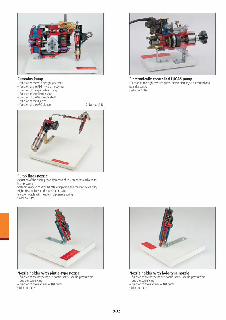
Pump-lines-nozzleActuation of the pump piston by means of roller tappet to achieve the high pressure.Solenoid valve to control the rate of injection and the start of delivery.High-pressure lines to the injection nozzle.Injection nozzle with needle and pressure spring.Order no. 1196
Cummins Pump– function of the VS flyweight governor– function of the PTG flyweight governor– function of the gear wheel pump– function of the throttle shaft– function of the VS throttle shaft– function of the injector– function of the AFC plunger Order no. 1140
Electronically controlled LUCAS pumpFunction of the high-pressure pump, distribution, injection control and quantity control Order no. 1087
Nozzle holder with pintle-type nozzle– function of the nozzle holder, nozzle, nozzle needle, pressure pin
and pressure spring– function of the inlet and outlet ductsOrder no. 1173
Nozzle holder with hole-type nozzle– function of the nozzle holder, nozzle, nozzle needle, pressure pin
and pressure spring– function of the inlet and outlet ductsOrder no. 1174
9-32
9
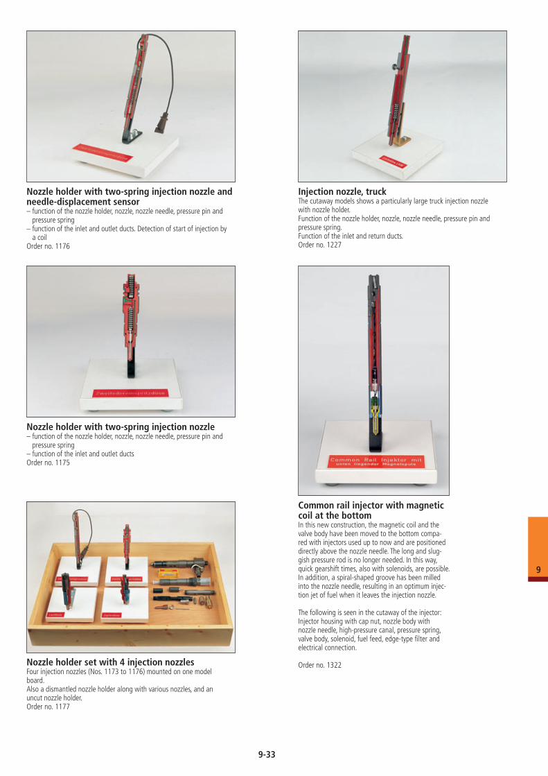
Nozzle holder with two-spring injection nozzle and needle-displacement sensor– function of the nozzle holder, nozzle, nozzle needle, pressure pin and
pressure spring – function of the inlet and outlet ducts. Detection of start of injection by
a coilOrder no. 1176
Injection nozzle, truckThe cutaway models shows a particularly large truck injection nozzle with nozzle holder.Function of the nozzle holder, nozzle, nozzle needle, pressure pin and pressure spring.Function of the inlet and return ducts.Order no. 1227
Nozzle holder with two-spring injection nozzle– function of the nozzle holder, nozzle, nozzle needle, pressure pin and
pressure spring– function of the inlet and outlet ductsOrder no. 1175
Nozzle holder set with 4 injection nozzlesFour injection nozzles (Nos. 1173 to 1176) mounted on one model board.Also a dismantled nozzle holder along with various nozzles, and an uncut nozzle holder.Order no. 1177
Common rail injector with magnetic coil at the bottomIn this new construction, the magnetic coil and the valve body have been moved to the bottom compa-red with injectors used up to now and are positioned directly above the nozzle needle. The long and slug- gish pressure rod is no longer needed. In this way, quick gearshift times, also with solenoids, are possible. In addition, a spiral-shaped groove has been milled into the nozzle needle, resulting in an optimum injec-tion jet of fuel when it leaves the injection nozzle.
The following is seen in the cutaway of the injector:Injector housing with cap nut, nozzle body with nozzle needle, high-pressure canal, pressure spring, valve body, solenoid, fuel feed, edge-type filter and electrical connection.
Order no. 1322
9-33
9
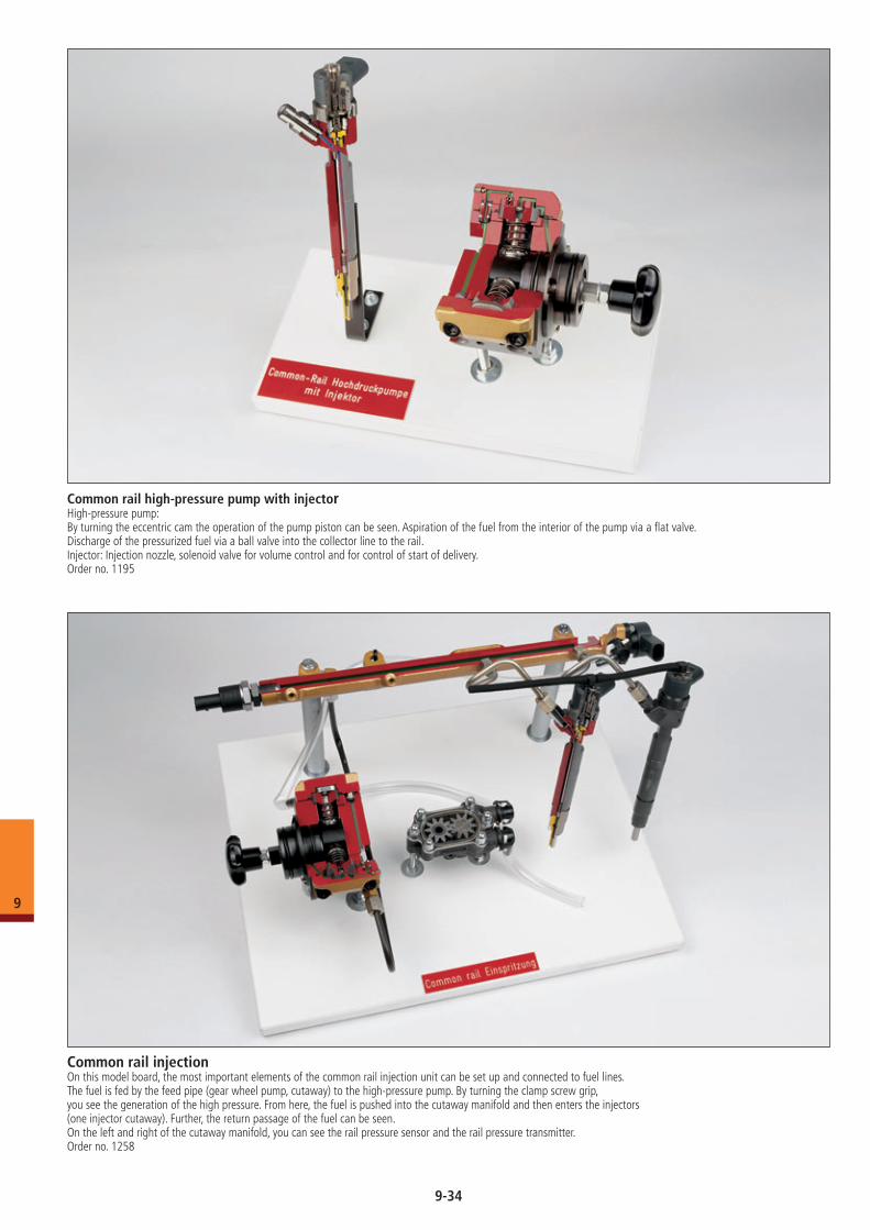
Common rail high-pressure pump with injectorHigh-pressure pump: By turning the eccentric cam the operation of the pump piston can be seen. Aspiration of the fuel from the interior of the pump via a flat valve. Discharge of the pressurized fuel via a ball valve into the collector line to the rail.Injector: Injection nozzle, solenoid valve for volume control and for control of start of delivery.Order no. 1195
Common rail injectionOn this model board, the most important elements of the common rail injection unit can be set up and connected to fuel lines. The fuel is fed by the feed pipe (gear wheel pump, cutaway) to the high-pressure pump. By turning the clamp screw grip, you see the generation of the high pressure. From here, the fuel is pushed into the cutaway manifold and then enters the injectors (one injector cutaway). Further, the return passage of the fuel can be seen.On the left and right of the cutaway manifold, you can see the rail pressure sensor and the rail pressure transmitter.Order no. 1258
9-34
9
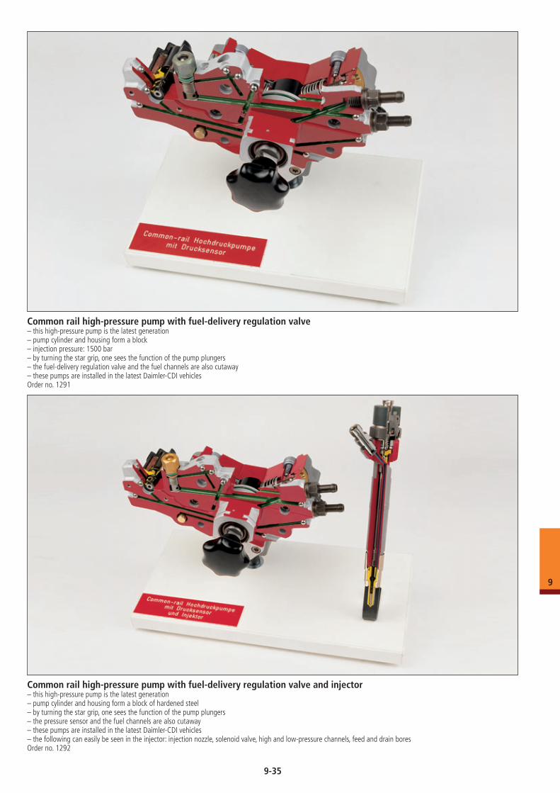
Common rail high-pressure pump with fuel-delivery regulation valve– this high-pressure pump is the latest generation– pump cylinder and housing form a block– injection pressure: 1500 bar– by turning the star grip, one sees the function of the pump plungers– the fuel-delivery regulation valve and the fuel channels are also cutaway– these pumps are installed in the latest Daimler-CDI vehiclesOrder no. 1291
Common rail high-pressure pump with fuel-delivery regulation valve and injector– this high-pressure pump is the latest generation– pump cylinder and housing form a block of hardened steel– by turning the star grip, one sees the function of the pump plungers– the pressure sensor and the fuel channels are also cutaway– these pumps are installed in the latest Daimler-CDI vehicles– the following can easily be seen in the injector: injection nozzle, solenoid valve, high and low-pressure channels, feed and drain bores Order no. 1292
9-35
9
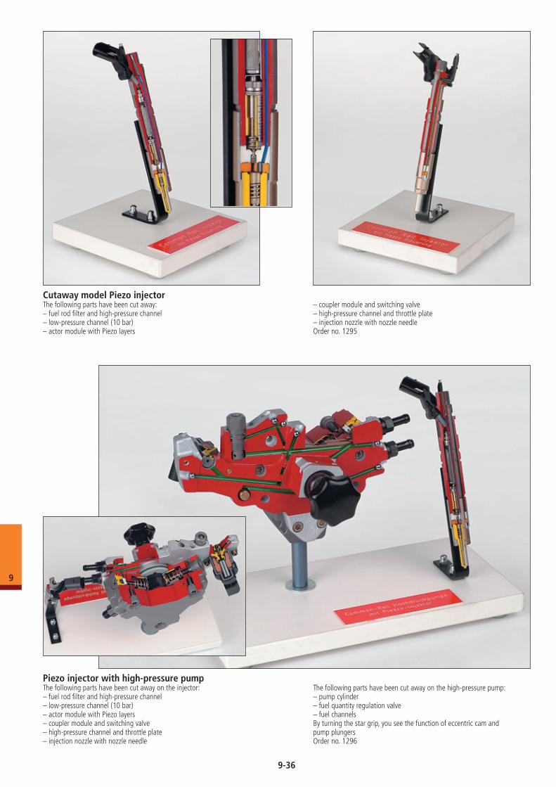
Cutaway model Piezo injector The following parts have been cut away: – fuel rod filter and high-pressure channel– low-pressure channel (10 bar)– actor module with Piezo layers
– coupler module and switching valve– high-pressure channel and throttle plate– injection nozzle with nozzle needleOrder no. 1295
Piezo injector with high-pressure pumpThe following parts have been cut away on the injector:– fuel rod filter and high-pressure channel– low-pressure channel (10 bar)– actor module with Piezo layers– coupler module and switching valve– high-pressure channel and throttle plate– injection nozzle with nozzle needle
The following parts have been cut away on the high-pressure pump:– pump cylinder– fuel quantity regulation valve– fuel channelsBy turning the star grip, you see the function of eccentric cam and pump plungersOrder no. 1296
9-36
9
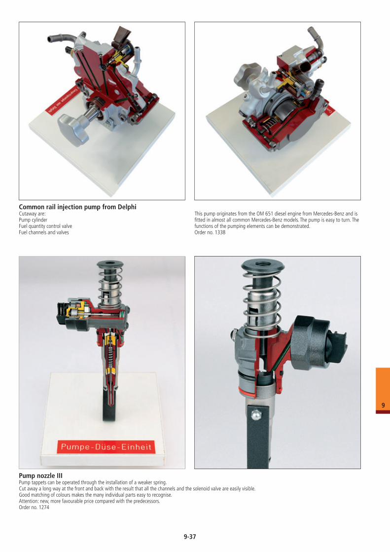
Common rail injection pump from DelphiCutaway are:Pump cylinderFuel quantity control valveFuel channels and valves
This pump originates from the OM 651 diesel engine from Mercedes-Benz and is fitted in almost all common Mercedes-Benz models. The pump is easy to turn. The functions of the pumping elements can be demonstrated. Order no. 1338
Pump nozzle IIIPump tappets can be operated through the installation of a weaker spring. Cut away a long way at the front and back with the result that all the channels and the solenoid valve are easily visible.Good matching of colours makes the many individual parts easy to recognise.Attention: new, more favourable price compared with the predecessors. Order no. 1274
9-37
9
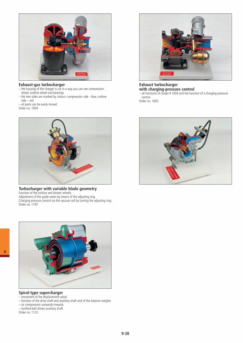
Exhaust-gas turbocharger– the housing of the charger is cut in a way you can see compression
wheel, turbine wheel and bearings– the two sides are marked by colours: compression side - blue, turbine
side – red– all parts can be easily movedOrder no. 1004
Exhaust turbocharger with charging-pressure control– all functions of model # 1004 and the function of a charging-pressure
controlOrder no. 1005
Turbocharger with variable blade geometryFunction of the turbine and blower wheels.Adjustment of the guide vanes by means of the adjusting ring.Charging-pressure control via the vacuum cell by turning the adjusting ring.Order no. 1197
Spiral-type supercharger– movement of the displacement spiral– function of the drive shaft and auxiliary shaft and of the balance weights– air compression outwards-inwards– toothed-belt driven auxiliary shaft Order no. 1122
9-38
9
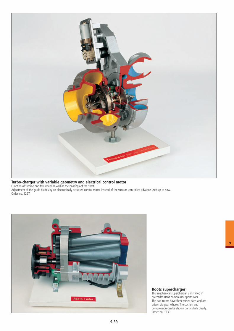
Turbo-charger with variable geometry and electrical control motorFunction of turbine and fan wheel as well as the bearings of the shaft.Adjustment of the guide blades by an electronically actuated control motor instead of the vacuum-controlled advance used up to now.Order no. 1267
Roots superchargerThis mechanical supercharger is installed in Mercedes-Benz compressor sports cars. The two rotors have three vanes each and are driven via gear wheels. The suction and compression can be shown particularly clearly. Order no. 1239
9-39
9
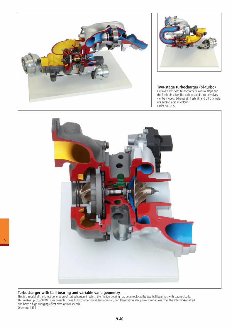
Turbocharger with ball bearing and variable vane geometryThis is a model of the latest generation of turbochargers in which the friction bearing has been replaced by two ball bearings with ceramic balls. This makes up to 300,000 rpm possible. These turbochargers have less abrasion, can transmit greater powers, suffer less from the afterworker effect and have a high charging effect even at low speeds. Order no. 1331
Two-stage turbocharger (bi-turbo)Cutaway are: both turbochargers, control flaps and the fresh-air valve. The turbines and throttle valves can be moved. Exhaust air, fresh air and oil channels are accentuated in colour. Order no. 1327
9-40
9
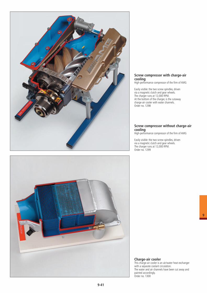
Screw compressor with charge-air coolingHigh-performance compressor of the firm of AMG
Easily visible: the two screw spindles, driven via a magnetic clutch and gear wheels.The charger runs at 12,000 RPM.At the bottom of the charger, is the cutawaycharge-air cooler with water channels.Order no. 1298
Screw compressor without charge-air coolingHigh-performance compressor of the firm of AMG
Easily visible: the two screw spindles, driven via a magnetic clutch and gear wheels.The charger runs at 12,000 RPM.Order no. 1299
Charge-air coolerThis charge-air cooler is an air/water heat exchanger with a separate coolant circulation.The water and air channels have been cut away and painted accordingly.Order no. 1300
9-41
9
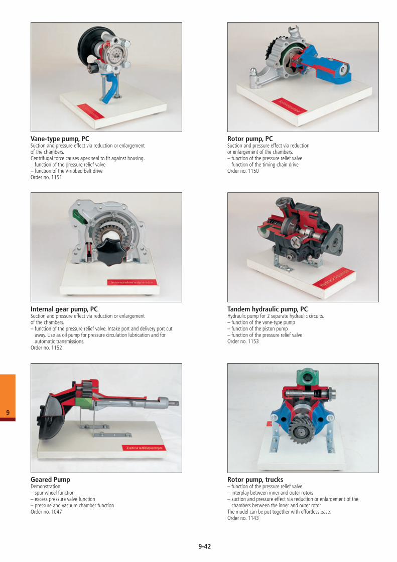
Vane-type pump, PCSuction and pressure effect via reduction or enlargement of the chambers.Centrifugal force causes apex seal to fit against housing.– function of the pressure relief valve– function of the V-ribbed belt driveOrder no. 1151
Internal gear pump, PCSuction and pressure effect via reduction or enlargement of the chambers.– function of the pressure relief valve. Intake port and delivery port cut
away. Use as oil pump for pressure circulation lubrication and for automatic transmissions.
Order no. 1152
Rotor pump, PCSuction and pressure effect via reductionor enlargement of the chambers.– function of the pressure relief valve– function of the timing chain driveOrder no. 1150
Tandem hydraulic pump, PCHydraulic pump for 2 separate hydraulic circuits. – function of the vane-type pump– function of the piston pump– function of the pressure relief valveOrder no. 1153
Geared PumpDemonstration:– spur wheel function– excess pressure valve function– pressure and vacuum chamber functionOrder no. 1047
Rotor pump, trucks– function of the pressure relief valve– interplay between inner and outer rotors– suction and pressure effect via reduction or enlargement of the
chambers between the inner and outer rotor The model can be put together with effortless ease.Order no. 1143
9-42
9
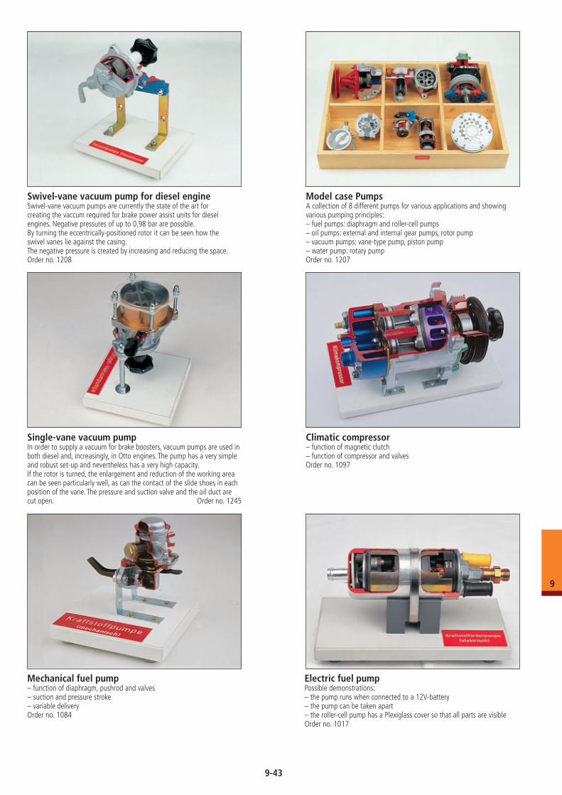
Climatic compressor– function of magnetic clutch– function of compressor and valvesOrder no. 1097
Swivel-vane vacuum pump for diesel engineSwivel-vane vacuum pumps are currently the state of the art for creating the vaccum required for brake power assist units for diesel engines. Negative pressures of up to 0,98 bar are possible.By turning the eccentrically-positioned rotor it can be seen how the swivel vanes lie against the casing.The negative pressure is created by increasing and reducing the space.Order no. 1208
Model case PumpsA collection of 8 different pumps for various applications and showing various pumping principles:– fuel pumps: diaphragm and roller-cell pumps– oil pumps: external and internal gear pumps, rotor pump– vacuum pumps: vane-type pump, piston pump– water pump: rotary pumpOrder no. 1207
Single-vane vacuum pumpIn order to supply a vacuum for brake boosters, vacuum pumps are used in both diesel and, increasingly, in Otto engines. The pump has a very simple and robust set-up and nevertheless has a very high capacity.If the rotor is turned, the enlargement and reduction of the working area can be seen particularly well, as can the contact of the slide shoes in each position of the vane. The pressure and suction valve and the oil duct are cut open. Order no. 1245
Mechanical fuel pump– function of diaphragm, pushrod and valves– suction and pressure stroke– variable deliveryOrder no. 1084
Electric fuel pumpPossible demonstrations: – the pump runs when connected to a 12V-battery– the pump can be taken apart– the roller-cell pump has a Plexiglass cover so that all parts are visibleOrder no. 1017
9-43
9
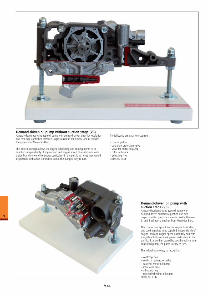
Demand-driven oil pump with suction stage (V8)A newly developed vane-type oil pump with demand-driven quantity regulation and two map-controlled pressure stages is used in the new 6- and 8-cylinder V engines from Mercedes-Benz.
This control concept allows the engine lubricating and cooling points to be supplied independently of engine load and engine speed absolutely and with a significantly lower drive power particularly in the part-load range than would be possible with a non-controlled pump. The pump is easy to turn.
The following are easy to recognise:
– control piston– cold-start protection valve– valve for motor oil pump– rotor with vane– adjusting ring – toothed wheel for oil pumpOrder no. 1342
Demand-driven oil pump without suction stage (V6)A newly developed vane-type oil pump with demand-driven quantity regulation and two map-controlled pressure stages is used in the new 6- and 8-cylinder V engines from Mercedes-Benz.
This control concept allows the engine lubricating and cooling points to be supplied independently of engine load and engine speed absolutely and with a significantly lower drive power particularly in the part-load range than would be possible with a non-controlled pump. The pump is easy to turn.
The following are easy to recognise:
– control piston– cold-start protection valve– valve for motor oil pump– rotor with vane– adjusting ringOrder no. 1341
9-44
9
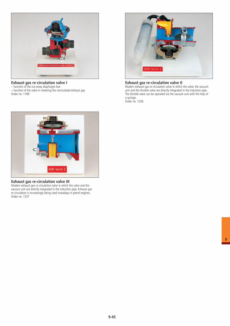
Exhaust gas re-circulation valve I– function of the cut-away diaphragm box– function of the valve in metering the recirculated exhaust gasOrder no. 1189
Exhaust gas re-circulation valve IIModern exhaust gas re-circulation valve in which the valve, the vacuum unit and the throttle valve are directly integrated in the induction pipe. The throttle valve can be operated via the vacuum unit with the help of a syringe.Order no. 1256
Exhaust gas re-circulation valve IIIModern exhaust gas re-circulation valve in which the valve and the vacuum unit are directly integrated in the induction pipe. Exhaust gas re-circulation is increasingly being used nowadays in petrol engines.Order no. 1257
9-45
9
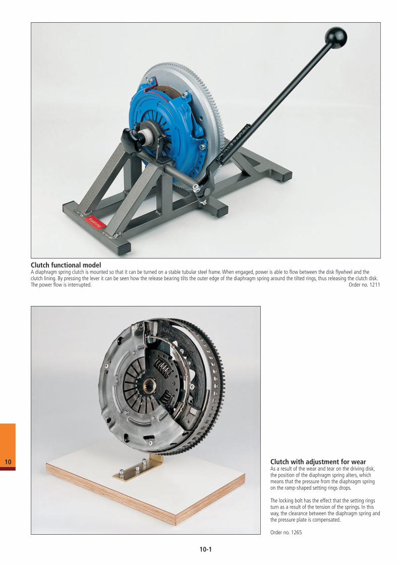
Clutch functional modelA diaphragm spring clutch is mounted so that it can be turned on a stable tubular steel frame. When engaged, power is able to flow between the disk flywheel and the clutch lining. By pressing the lever it can be seen how the release bearing tilts the outer edge of the diaphragm spring around the tilted rings, thus releasing the clutch disk. The power flow is interrupted. Order no. 1211
Clutch with adjustment for wearAs a result of the wear and tear on the driving disk, the position of the diaphragm spring alters, which means that the pressure from the diaphragm spring on the ramp-shaped setting rings drops.
The locking bolt has the effect that the setting rings turn as a result of the tension of the springs. In this way, the clearance between the diaphragm spring and the pressure plate is compensated.
Order no. 1265
10
10-1
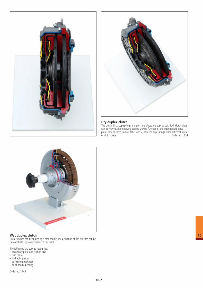
Dry duplex clutch The clutch discs, cup springs and pressure plates are easy to see. Both clutch discs can be moved. The following can be shown: function of the intermediate drive plate, flow of force from clutch 1 and 2, how the cup springs work, different sizes of clutch discs. Order no. 1334
Wet duplex clutchBoth clutches can be turned by a star handle. The actuation of the clutches can be demonstrated by compression of the discs.
The following are easy to recognize:– secondary plate and friction disc– disc carrier– hydraulic piston– coil spring packages– axial needle bearing
Order no. 1345
10
10-2
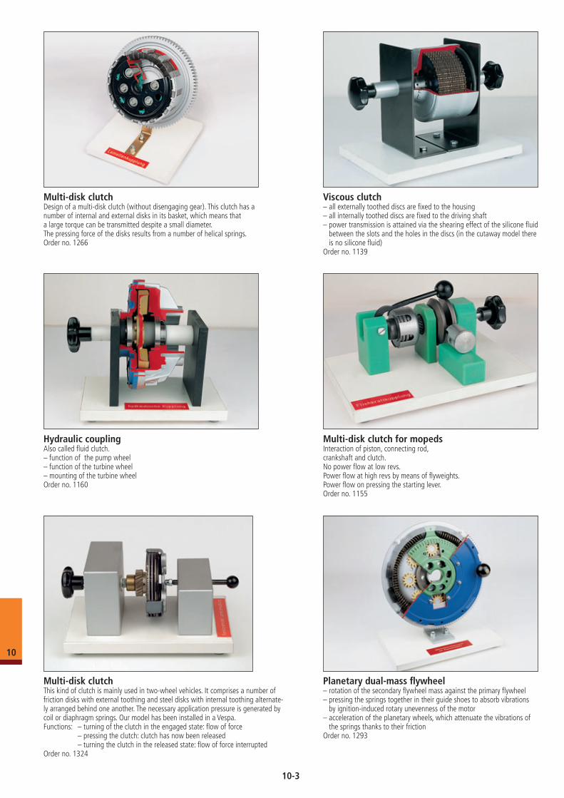
Viscous clutch– all externally toothed discs are fixed to the housing– all internally toothed discs are fixed to the driving shaft– power transmission is attained via the shearing effect of the silicone fluid
between the slots and the holes in the discs (in the cutaway model there is no silicone fluid)
Order no. 1139
Multi-disk clutch for mopedsInteraction of piston, connecting rod,crankshaft and clutch.No power flow at low revs.Power flow at high revs by means of flyweights.Power flow on pressing the starting lever.Order no. 1155
Hydraulic couplingAlso called fluid clutch.– function of the pump wheel– function of the turbine wheel– mounting of the turbine wheelOrder no. 1160
Planetary dual-mass flywheel– rotation of the secondary flywheel mass against the primary flywheel– pressing the springs together in their guide shoes to absorb vibrations
by ignition-induced rotary unevenness of the motor– acceleration of the planetary wheels, which attenuate the vibrations of
the springs thanks to their frictionOrder no. 1293
Multi-disk clutchDesign of a multi-disk clutch (without disengaging gear). This clutch has a number of internal and external disks in its basket, which means that a large torque can be transmitted despite a small diameter. The pressing force of the disks results from a number of helical springs.Order no. 1266
Multi-disk clutchThis kind of clutch is mainly used in two-wheel vehicles. It comprises a number of friction disks with external toothing and steel disks with internal toothing alternate-ly arranged behind one another. The necessary application pressure is generated by coil or diaphragm springs. Our model has been installed in a Vespa.Functions: – turning of the clutch in the engaged state: flow of force – pressing the clutch: clutch has now been released – turning the clutch in the released state: flow of force interruptedOrder no. 1324
10
10-3
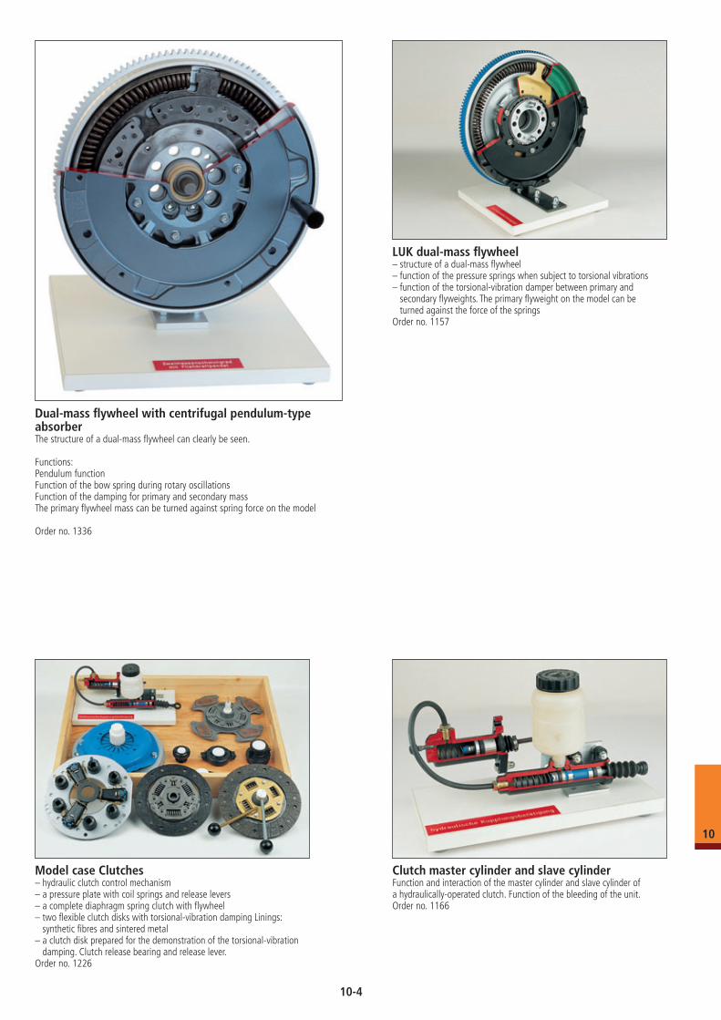
Clutch master cylinder and slave cylinderFunction and interaction of the master cylinder and slave cylinder of a hydraulically-operated clutch. Function of the bleeding of the unit.Order no. 1166
Model case Clutches– hydraulic clutch control mechanism– a pressure plate with coil springs and release levers– a complete diaphragm spring clutch with flywheel– two flexible clutch disks with torsional-vibration damping Linings:
synthetic fibres and sintered metal– a clutch disk prepared for the demonstration of the torsional-vibration
damping. Clutch release bearing and release lever.Order no. 1226
LUK dual-mass flywheel– structure of a dual-mass flywheel– function of the pressure springs when subject to torsional vibrations– function of the torsional-vibration damper between primary and
secondary flyweights. The primary flyweight on the model can be turned against the force of the springs
Order no. 1157
Dual-mass flywheel with centrifugal pendulum-type absorberThe structure of a dual-mass flywheel can clearly be seen.
Functions:Pendulum functionFunction of the bow spring during rotary oscillationsFunction of the damping for primary and secondary massThe primary flywheel mass can be turned against spring force on the model
Order no. 1336
10
10-4
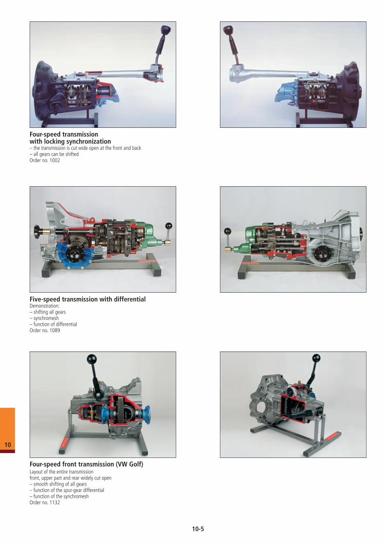
Five-speed transmission with differentialDemonstration: – shifting all gears– synchromesh– function of differentialOrder no. 1089
Four-speed transmission with locking synchronization– the transmission is cut wide open at the front and back– all gears can be shiftedOrder no. 1002
Four-speed front transmission (VW Golf) Layout of the entire transmissionfront, upper part and rear widely cut open– smooth shifting of all gears– function of the spur-gear differential– function of the synchromeshOrder no. 1132
10
10-5
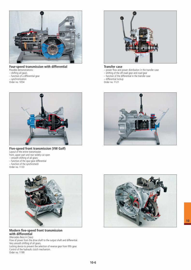
Modern five-speed front transmission with differential(Mercedes-Benz A Class)Flow of power from the drive shaft to the output shaft and differential. Very smooth shifting of all gears. Locking device to prevent the selection of reverse gear from fifth gear.Control of the hydraulic clutch mechanism.Order no. 1199
Five-speed front transmission (VW Golf)Layout of the entire transmissionfront, upper part and rear widely cut open– smooth shifting of all gears– function of the spur-gear differential– function of the synchromeshOrder no. 1133
Four-speed transmission with differentialPossible demonstrations: – shifting all gears– function of a differential gear– synchronizationOrder no. 1054
Transfer case– power flow and power distribution in the transfer case– shifting of the off-road gear and road gear– function of the differential in the transfer case– differential lockupOrder no. 1121
10
10-6
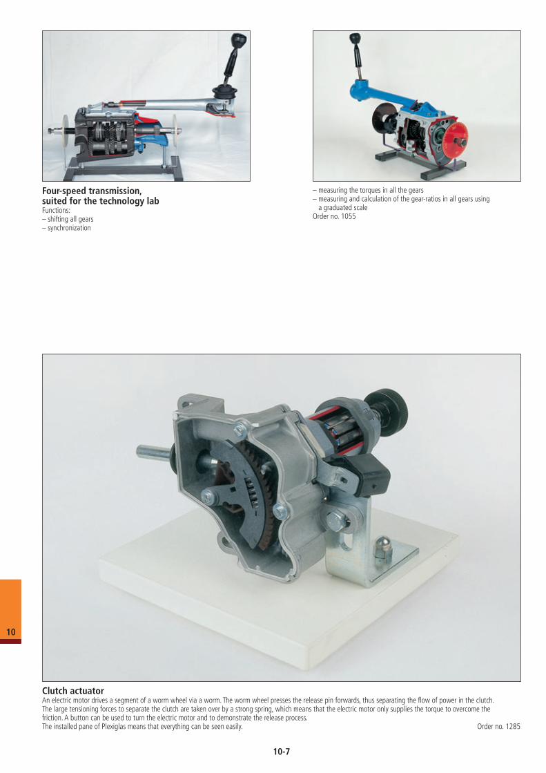
Four-speed transmission, suited for the technology labFunctions: – shifting all gears– synchronization
– measuring the torques in all the gears– measuring and calculation of the gear-ratios in all gears using
a graduated scaleOrder no. 1055
Clutch actuatorAn electric motor drives a segment of a worm wheel via a worm. The worm wheel presses the release pin forwards, thus separating the flow of power in the clutch. The large tensioning forces to separate the clutch are taken over by a strong spring, which means that the electric motor only supplies the torque to overcome the friction. A button can be used to turn the electric motor and to demonstrate the release process. The installed pane of Plexiglas means that everything can be seen easily. Order no. 1285
10
10-7
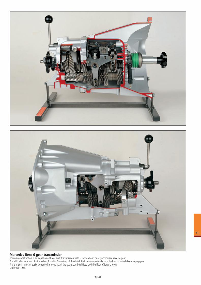
Mercedes-Benz 6-gear transmissionThis new construction is an equal-axle three-shaft transmission with 6 forward and one synchronised reverse gear.The shift elements are distributed on 2 shafts. Operation of the clutch is done automatically via a hydraulic central disengaging gear. The transmission can easily be turned in neutral. All the gears can be shifted and the flow of force shown.Order no. 1255
10
10-8
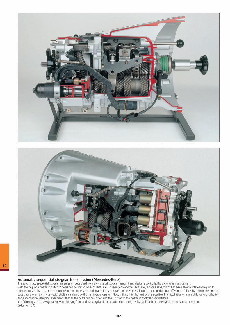
Automatic sequential six-gear transmission (Mercedes-Benz)The automated, sequential six-gear transmission developed from the classical six-gear manual transmission is controlled by the engine management. With the help of a hydraulic piston, 2 gears can be shifted on each shift level. To change to another shift level, a gate sleeve, which had been able to rotate loosely up to then, is arrested by a second hydraulic piston. In this way, the old gear is firstly removed and then the selector shaft turned onto a different shift level by a pin in the arrested gate sleeve when the inlet selector shaft is displaced by the first hydraulic piston. Now, shifting into the next gear is possible. The installation of a gearshift rod with a button and a mechanical clamping lever means that all the gears can be shifted and the function of the hydraulic controls demonstrated.The following are cut away: transmission housing front and back, hydraulic pump with electric engine, hydraulic unit and the hydraulic pressure accumulator. 0rder no. 1282
10
10-9
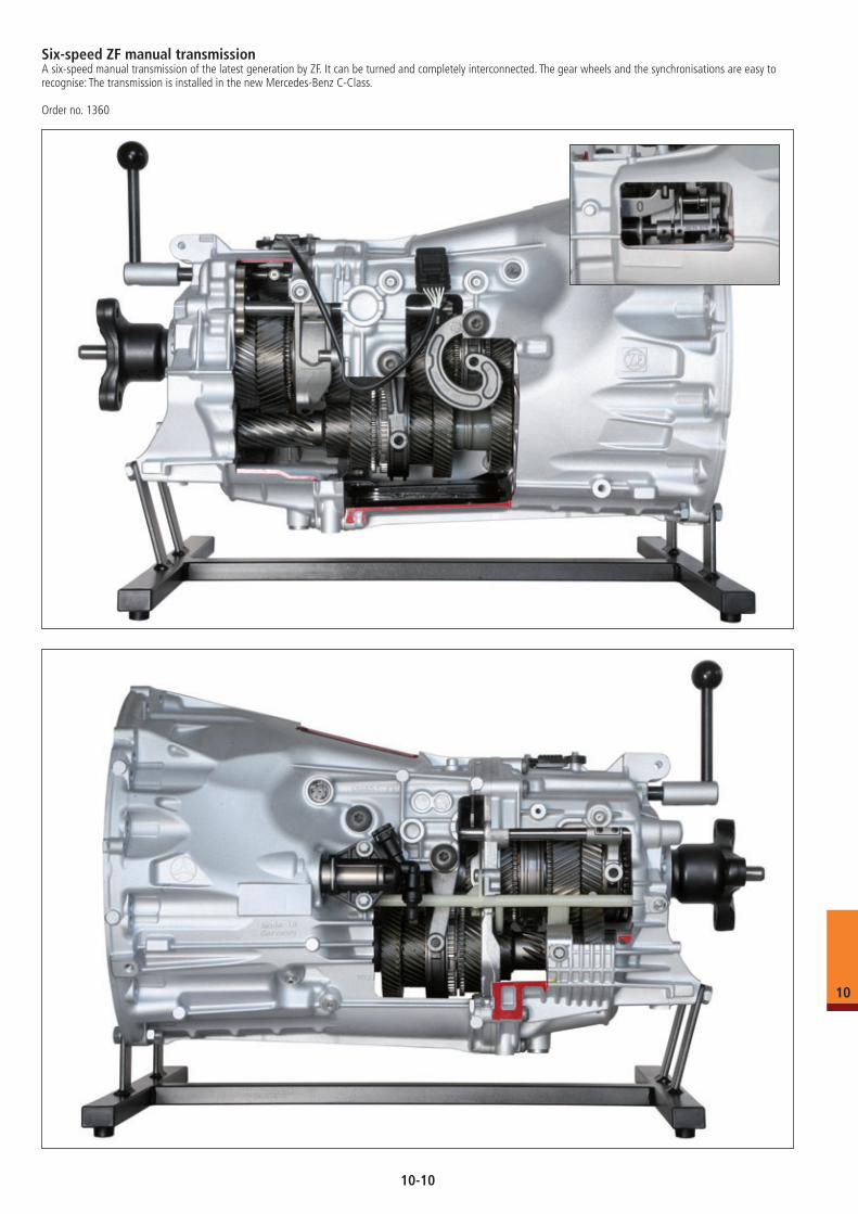
Six-speed ZF manual transmissionA six-speed manual transmission of the latest generation by ZF. It can be turned and completely interconnected. The gear wheels and the synchronisations are easy to recognise: The transmission is installed in the new Mercedes-Benz C-Class.
Order no. 1360
10
10-10
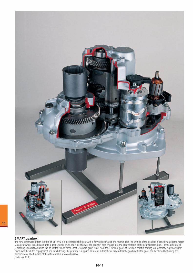
SMART gearboxThe new construction from the firm of GETRAG is a mechanical shift gear with 6 forward gears and one reverse gear. The shifting of the gearbox is done by an electric motor via a gear wheel transmission onto a gear selector drum. The slide shoes of the gearshift rods engage into the groove tracks of the gear selector drum. For the differential, 2 differing transmission ratios can be shifted, which means that 6 forward gears result from the 3 forward gears of the main shaft.In shifting, an automatic clutch actuator takes over the clutch engagement and de-clutching. The gearbox is supplied as a semi-automatic or fully automatic gearbox. All the gears can be shifted by turning the electric motor. The function of the differential is also easily visible.Order no. 1238
10
10-11
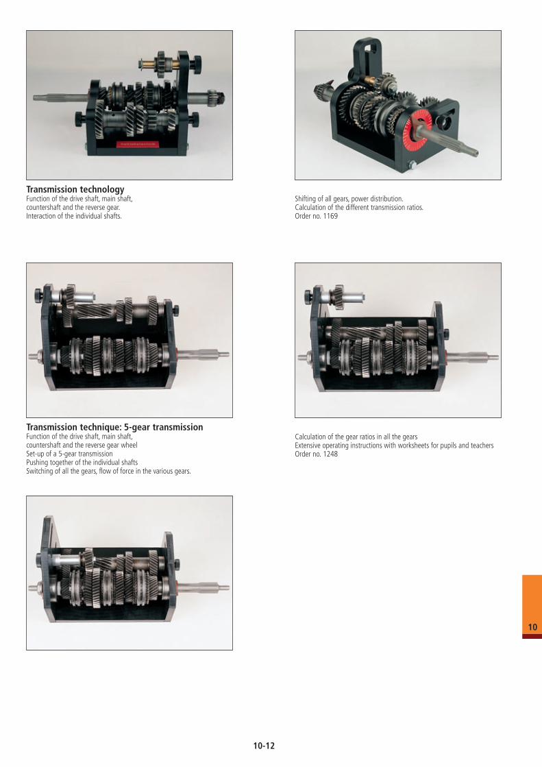
Transmission technologyFunction of the drive shaft, main shaft,countershaft and the reverse gear.Interaction of the individual shafts.
Shifting of all gears, power distribution.Calculation of the different transmission ratios.Order no. 1169
Transmission technique: 5-gear transmissionFunction of the drive shaft, main shaft,countershaft and the reverse gear wheelSet-up of a 5-gear transmissionPushing together of the individual shaftsSwitching of all the gears, flow of force in the various gears.
Calculation of the gear ratios in all the gearsExtensive operating instructions with worksheets for pupils and teachersOrder no. 1248
10
10-12
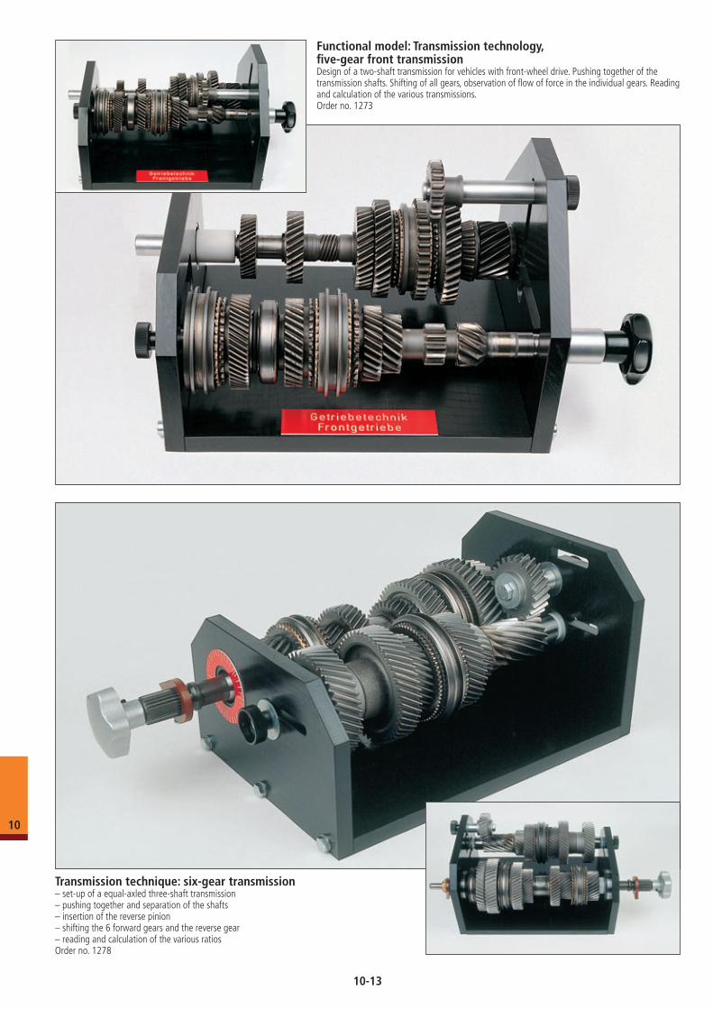
Functional model: Transmission technology, five-gear front transmissionDesign of a two-shaft transmission for vehicles with front-wheel drive. Pushing together of the transmission shafts. Shifting of all gears, observation of flow of force in the individual gears. Reading and calculation of the various transmissions.Order no. 1273
Transmission technique: six-gear transmission– set-up of a equal-axled three-shaft transmission– pushing together and separation of the shafts– insertion of the reverse pinion– shifting the 6 forward gears and the reverse gear– reading and calculation of the various ratiosOrder no. 1278
10
10-13
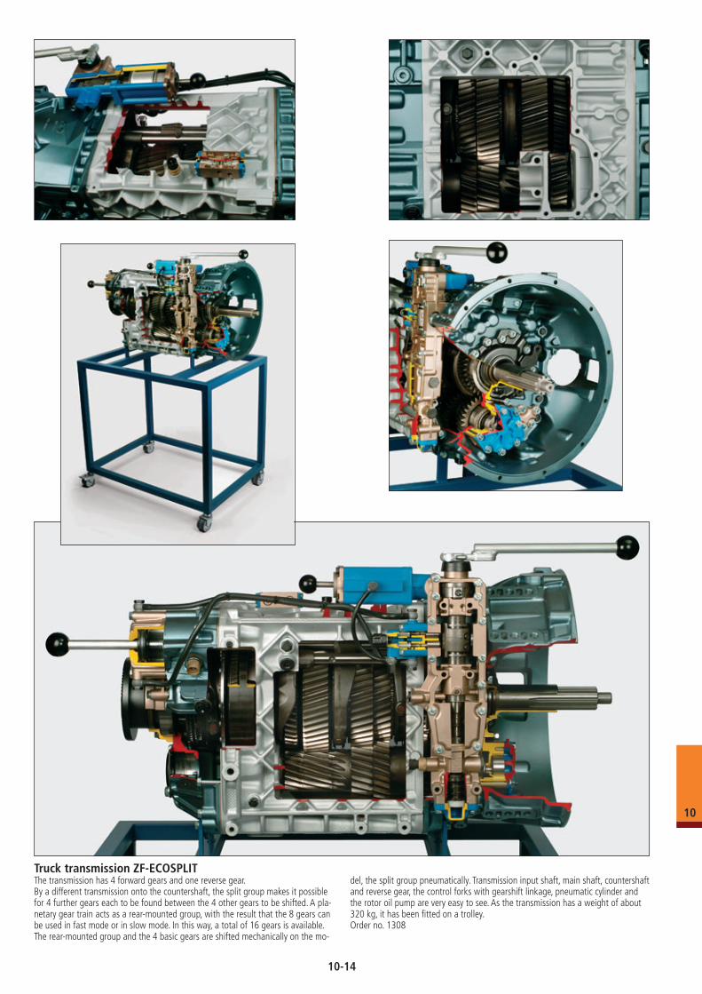
Truck transmission ZF-ECOSPLITThe transmission has 4 forward gears and one reverse gear.By a different transmission onto the countershaft, the split group makes it possiblefor 4 further gears each to be found between the 4 other gears to be shifted. A pla-netary gear train acts as a rear-mounted group, with the result that the 8 gears can be used in fast mode or in slow mode. In this way, a total of 16 gears is available. The rear-mounted group and the 4 basic gears are shifted mechanically on the mo-
del, the split group pneumatically. Transmission input shaft, main shaft, countershaft and reverse gear, the control forks with gearshift linkage, pneumatic cylinder and the rotor oil pump are very easy to see. As the transmission has a weight of about 320 kg, it has been fitted on a trolley.Order no. 1308
10
10-14
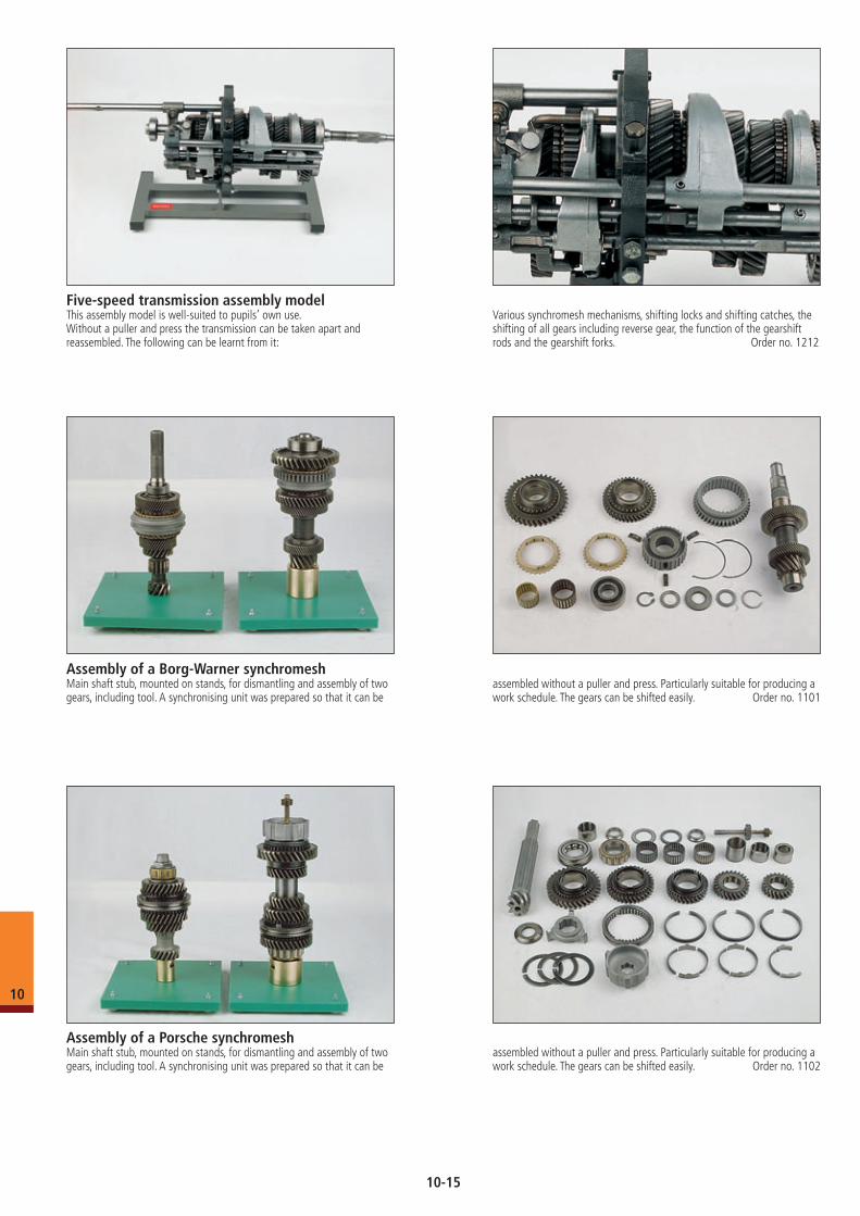
Five-speed transmission assembly modelThis assembly model is well-suited to pupils’ own use.Without a puller and press the transmission can be taken apart and reassembled. The following can be learnt from it:
Various synchromesh mechanisms, shifting locks and shifting catches, the shifting of all gears including reverse gear, the function of the gearshift rods and the gearshift forks. Order no. 1212
Assembly of a Porsche synchromeshMain shaft stub, mounted on stands, for dismantling and assembly of two gears, including tool. A synchronising unit was prepared so that it can be
assembled without a puller and press. Particularly suitable for producing a work schedule. The gears can be shifted easily. Order no. 1102
Assembly of a Borg-Warner synchromeshMain shaft stub, mounted on stands, for dismantling and assembly of two gears, including tool. A synchronising unit was prepared so that it can be
assembled without a puller and press. Particularly suitable for producing a work schedule. The gears can be shifted easily. Order no. 1101
10
10-15
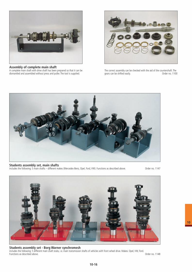
Assembly of complete main shaftA complete main shaft with drive shaft has been prepared so that it can be dismantled and assembled without press and puller. The tool is supplied.
The correct assembly can be checked with the aid of the countershaft. The gears can be shifted easily. Order no. 1100
Students assembly set, main shaftsincludes the following: 5 main shafts – different makes (Mercedes-Benz, Opel, Ford, VW). Functions as described above. Order no. 1147
Students assembly set - Borg Warner synchromeshincludes the following: 5 different main shaft stubs, i.e. main transmission shafts of vehicles with front wheel drive. Makes: Opel, VW, Ford. Functions as described above. Order no. 1148
10
10-16
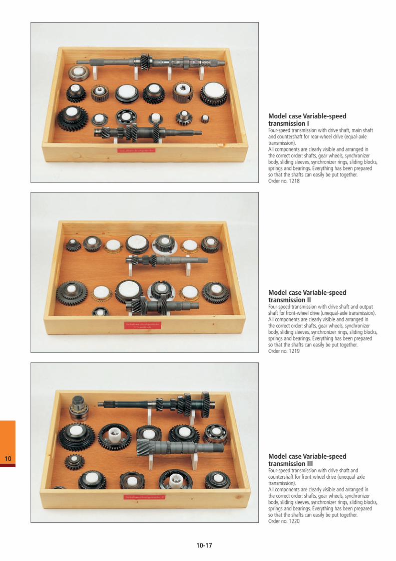
Model case Variable-speed transmission IFour-speed transmission with drive shaft, main shaft and countershaft for rear-wheel drive (equal-axle transmission).All components are clearly visible and arranged in the correct order: shafts, gear wheels, synchronizer body, sliding sleeves, synchronizer rings, sliding blocks, springs and bearings. Everything has been prepared so that the shafts can easily be put together.Order no. 1218
Model case Variable-speed transmission IIFour-speed transmission with drive shaft and output shaft for front-wheel drive (unequal-axle transmission).All components are clearly visible and arranged in the correct order: shafts, gear wheels, synchronizer body, sliding sleeves, synchronizer rings, sliding blocks, springs and bearings. Everything has been prepared so that the shafts can easily be put together.Order no. 1219
Model case Variable-speed transmission IIIFour-speed transmission with drive shaft and countershaft for front-wheel drive (unequal-axle transmission).All components are clearly visible and arranged in the correct order: shafts, gear wheels, synchronizer body, sliding sleeves, synchronizer rings, sliding blocks, springs and bearings. Everything has been prepared so that the shafts can easily be put together.Order no. 1220
10
10-17
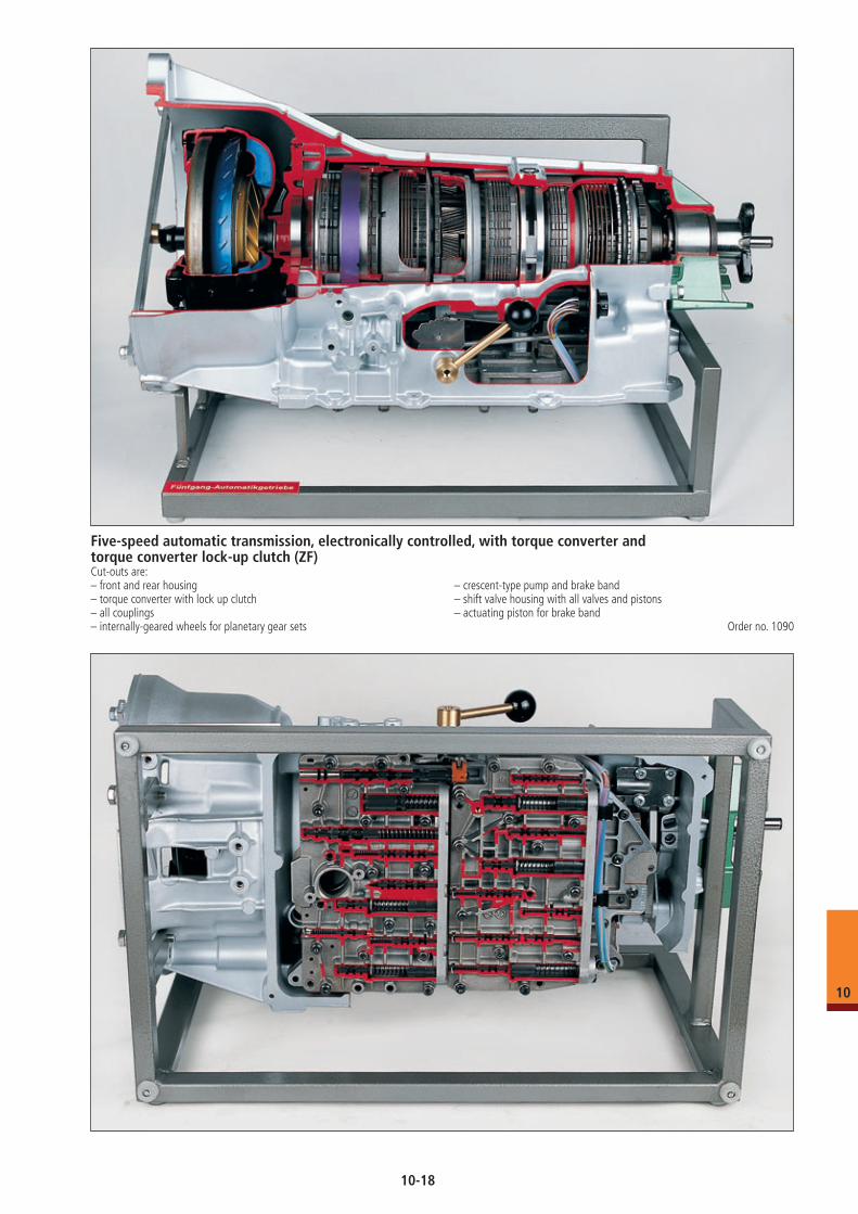
Five-speed automatic transmission, electronically controlled, with torque converter and torque converter lock-up clutch (ZF)Cut-outs are:– front and rear housing – crescent-type pump and brake band– torque converter with lock up clutch – shift valve housing with all valves and pistons– all couplings – actuating piston for brake band– internally-geared wheels for planetary gear sets Order no. 1090
10
10-18
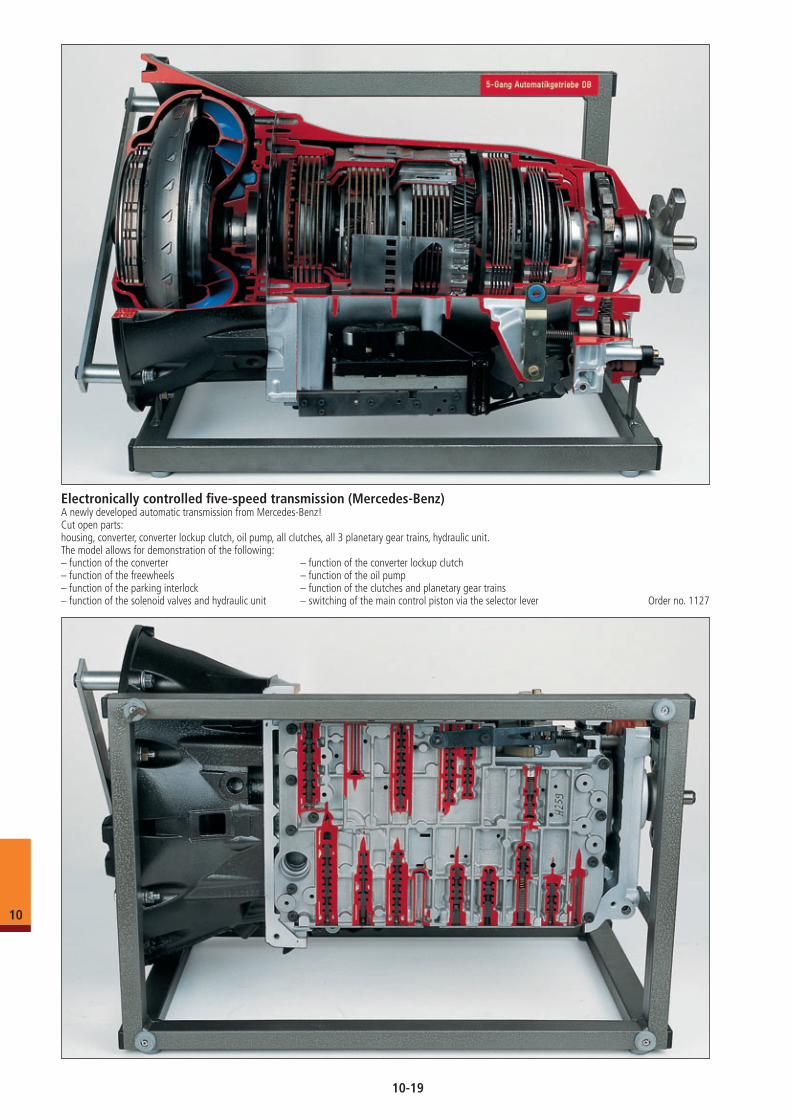
Electronically controlled five-speed transmission (Mercedes-Benz)A newly developed automatic transmission from Mercedes-Benz! Cut open parts:housing, converter, converter lockup clutch, oil pump, all clutches, all 3 planetary gear trains, hydraulic unit.The model allows for demonstration of the following:– function of the converter – function of the converter lockup clutch– function of the freewheels – function of the oil pump– function of the parking interlock – function of the clutches and planetary gear trains– function of the solenoid valves and hydraulic unit – switching of the main control piston via the selector lever Order no. 1127
10
10-19
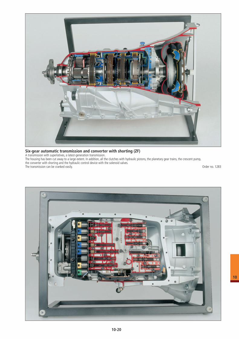
Six-gear automatic transmission and converter with shorting (ZF)A transmission with superlatives, a latest-generation transmission.The housing has been cut away to a large extent. In addition, all the clutches with hydraulic pistons, the planetary gear trains, the crescent pump, the converter with shorting and the hydraulic control device with the solenoid valves.The transmission can be cranked easily. Order no. 1283
10
10-20
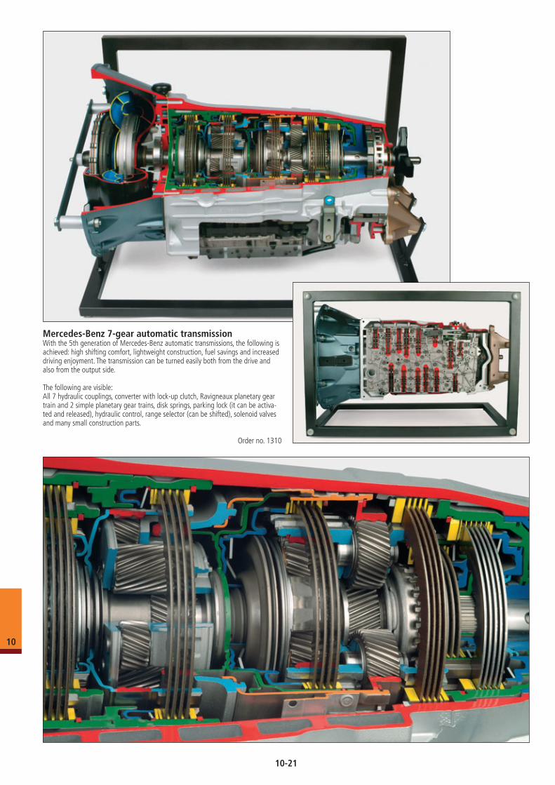
Mercedes-Benz 7-gear automatic transmissionWith the 5th generation of Mercedes-Benz automatic transmissions, the following is achieved: high shifting comfort, lightweight construction, fuel savings and increased driving enjoyment. The transmission can be turned easily both from the drive and also from the output side.
The following are visible:All 7 hydraulic couplings, converter with lock-up clutch, Ravigneaux planetary gear train and 2 simple planetary gear trains, disk springs, parking lock (it can be activa-ted and released), hydraulic control, range selector (can be shifted), solenoid valves and many small construction parts.
Order no. 1310
10
10-21
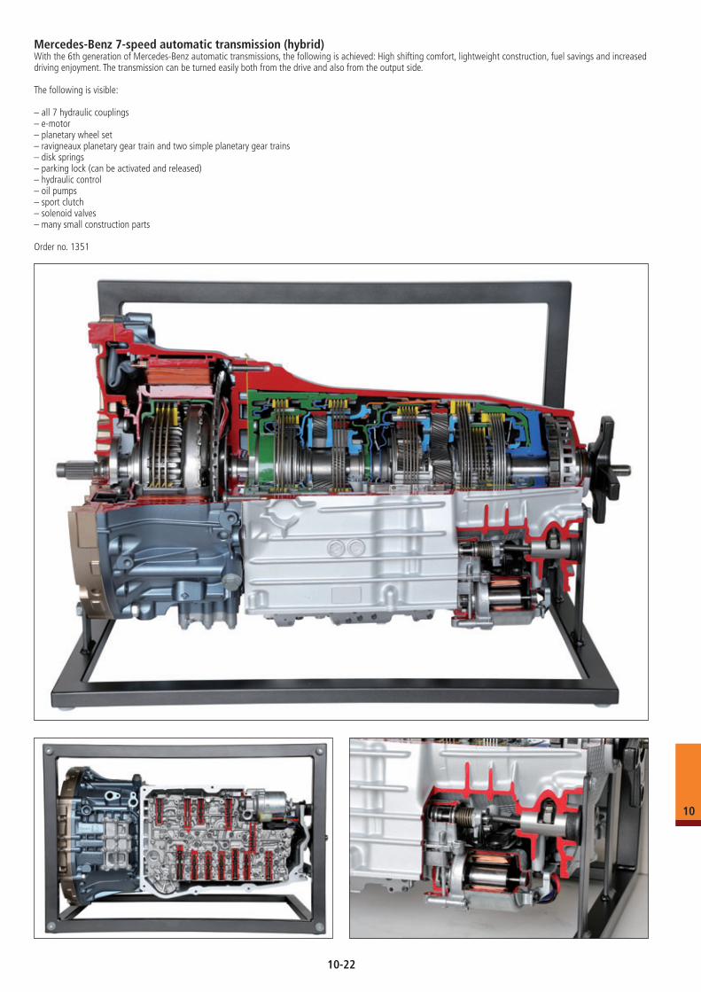
Mercedes-Benz 7-speed automatic transmission (hybrid)With the 6th generation of Mercedes-Benz automatic transmissions, the following is achieved: High shifting comfort, lightweight construction, fuel savings and increased driving enjoyment. The transmission can be turned easily both from the drive and also from the output side.
The following is visible:
– all 7 hydraulic couplings– e-motor– planetary wheel set– ravigneaux planetary gear train and two simple planetary gear trains– disk springs– parking lock (can be activated and released)– hydraulic control– oil pumps– sport clutch– solenoid valves– many small construction parts
Order no. 1351
10
10-22
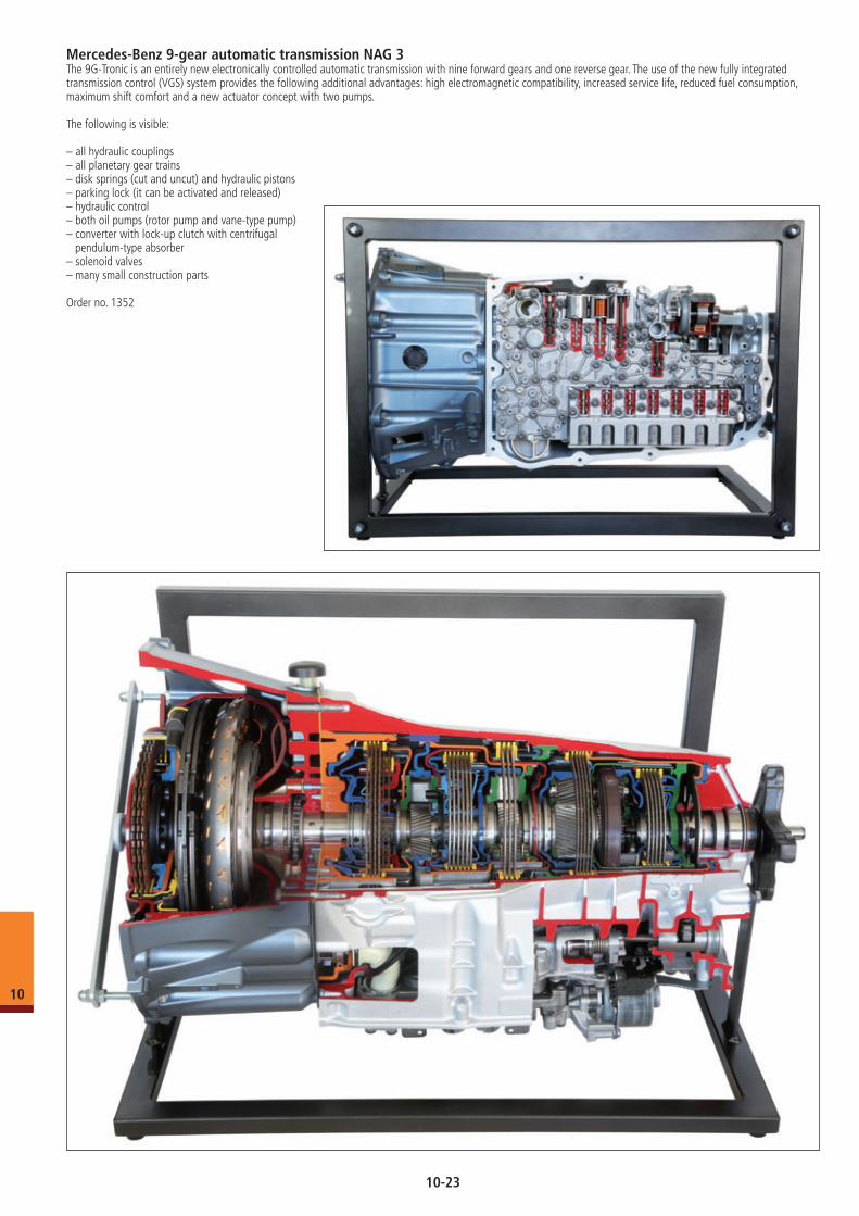
Mercedes-Benz 9-gear automatic transmission NAG 3The 9G-Tronic is an entirely new electronically controlled automatic transmission with nine forward gears and one reverse gear. The use of the new fully integrated transmission control (VGS) system provides the following additional advantages: high electromagnetic compatibility, increased service life, reduced fuel consumption, maximum shift comfort and a new actuator concept with two pumps.
The following is visible:
– all hydraulic couplings– all planetary gear trains– disk springs (cut and uncut) and hydraulic pistons– parking lock (it can be activated and released)– hydraulic control– both oil pumps (rotor pump and vane-type pump)– converter with lock-up clutch with centrifugal pendulum-type absorber– solenoid valves– many small construction parts
Order no. 1352
10
10-23
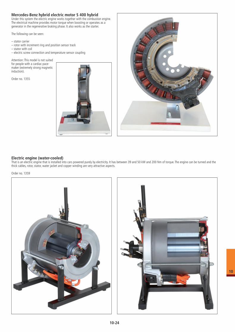
Mercedes-Benz hybrid electric motor S 400 hybridUnder this system the electric engine works together with the combustion engine. The electrical machine provides motor torque when boosting or operates as a generator in the regenerative braking phase. It also works as the starter.
The following can be seen:
– stator carrier– rotor with increment ring and position sensor track– stator with coil– electric screw connection and temperature sensor coupling
Attention: This model is not suited for people with a cardiac pace- maker (extremely strong magnetic induction).
Order no. 1355
Electric engine (water-cooled)That is an electric engine that is installed into cars powered purely by electricity. It has between 39 and 50 kW and 200 Nm of torque. The engine can be turned and the thick cables, rotor, stator, water jacket and copper winding are very attractive aspects.
Order no. 1359
10
10-24
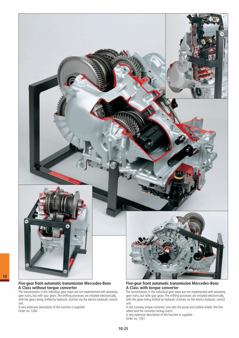
Five-gear front automatic transmission Mercedes-Benz A Class without torque converterThe transmissions in the individual gear steps are not implemented with planetary gear trains, but with spur gears. The shifting processes are initiated electronically, with the gears being shifted by hydraulic clutches via the electro-hydraulic control unit.A very extensive description of the function is supplied.Order no. 1260
Five-gear front automatic transmission Mercedes-Benz A Class with torque converterThe transmissions in the individual gear steps are not implemented with planetary gear trains, but with spur gears. The shifting processes are initiated electronically, with the gears being shifted by hydraulic clutches via the electro-hydraulic control unit.In the cutaway torque converter, one sees the pump and turbine wheel, the free-wheel and the converter lockup clutch.A very extensive description of the function is supplied.Order no. 1261
10
10-25
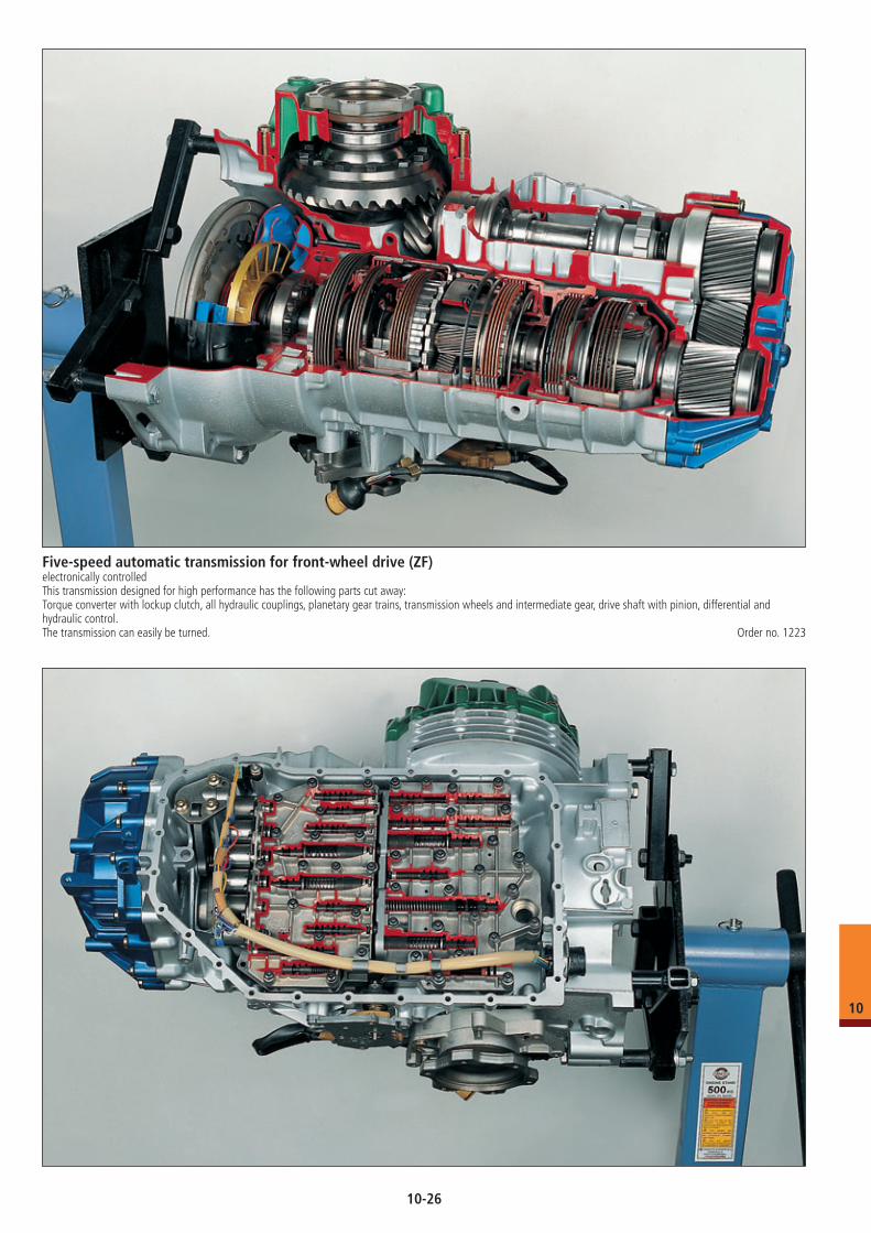
Five-speed automatic transmission for front-wheel drive (ZF)electronically controlledThis transmission designed for high performance has the following parts cut away:Torque converter with lockup clutch, all hydraulic couplings, planetary gear trains, transmission wheels and intermediate gear, drive shaft with pinion, differential and hydraulic control.The transmission can easily be turned. Order no. 1223
10
10-26
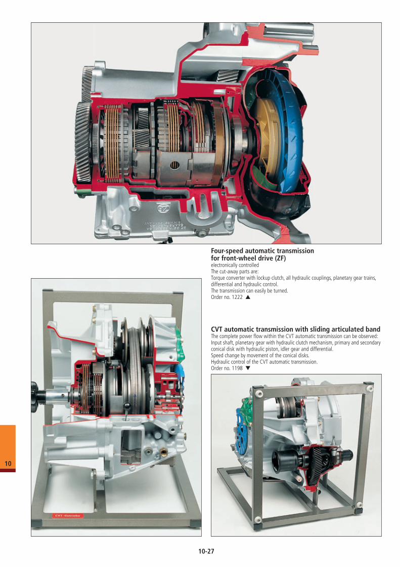
Four-speed automatic transmission for front-wheel drive (ZF)electronically controlledThe cut-away parts are:Torque converter with lockup clutch, all hydraulic couplings, planetary gear trains, differential and hydraulic control.The transmission can easily be turned.Order no. 1222 ▲
CVT automatic transmission with sliding articulated bandThe complete power flow within the CVT automatic transmission can be observed:Input shaft, planetary gear with hydraulic clutch mechanism, primary and secondary conical disk with hydraulic piston, idler gear and differential.Speed change by movement of the conical disks.Hydraulic control of the CVT automatic transmission.Order no. 1198 ▼
10
10-27
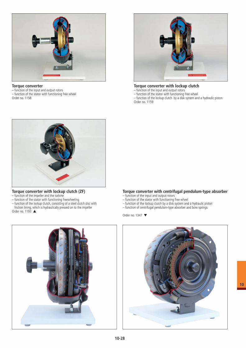
Torque converter– function of the input and output rotors– function of the stator with functioning free wheelOrder no. 1158
Torque converter with lockup clutch– function of the input and output rotors– function of the stator with functioning free wheel– function of the lockup clutch by a disk system and a hydraulic pistonOrder no. 1159
Torque converter with lockup clutch (ZF)– function of the impeller and the turbine– function of the stator with functioning freewheeling– function of the lockup clutch, consisting of a steel clutch disc with
friction lining, which is hydraulically pressed on to the impellerOrder no. 1193 ▲
Torque converter with centrifugal pendulum-type absorber– function of the input and output rotors– function of the stator with functioning free wheel– function of the lockup clutch by a disk system and a hydraulic piston– function of centrifugal pendulum-type absorber and bow springs
Order no. 1347 ▼
10
10-28
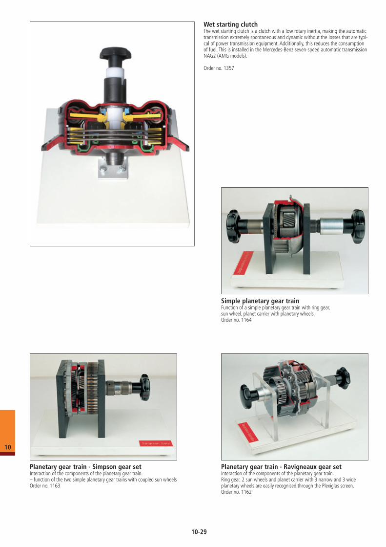
Simple planetary gear trainFunction of a simple planetary gear train with ring gear,sun wheel, planet carrier with planetary wheels.Order no. 1164
Planetary gear train - Simpson gear setInteraction of the components of the planetary gear train.– function of the two simple planetary gear trains with coupled sun wheelsOrder no. 1163
Planetary gear train - Ravigneaux gear setInteraction of the components of the planetary gear train.Ring gear, 2 sun wheels and planet carrier with 3 narrow and 3 wide planetary wheels are easily recognised through the Plexiglas screen.Order no. 1162
Wet starting clutchThe wet starting clutch is a clutch with a low rotary inertia, making the automatic transmission extremely spontaneous and dynamic without the losses that are typi-cal of power transmission equipment. Additionally, this reduces the consumption of fuel. This is installed in the Mercedes-Benz seven-speed automatic transmission NAG2 (AMG models).
Order no. 1357
10
10-29
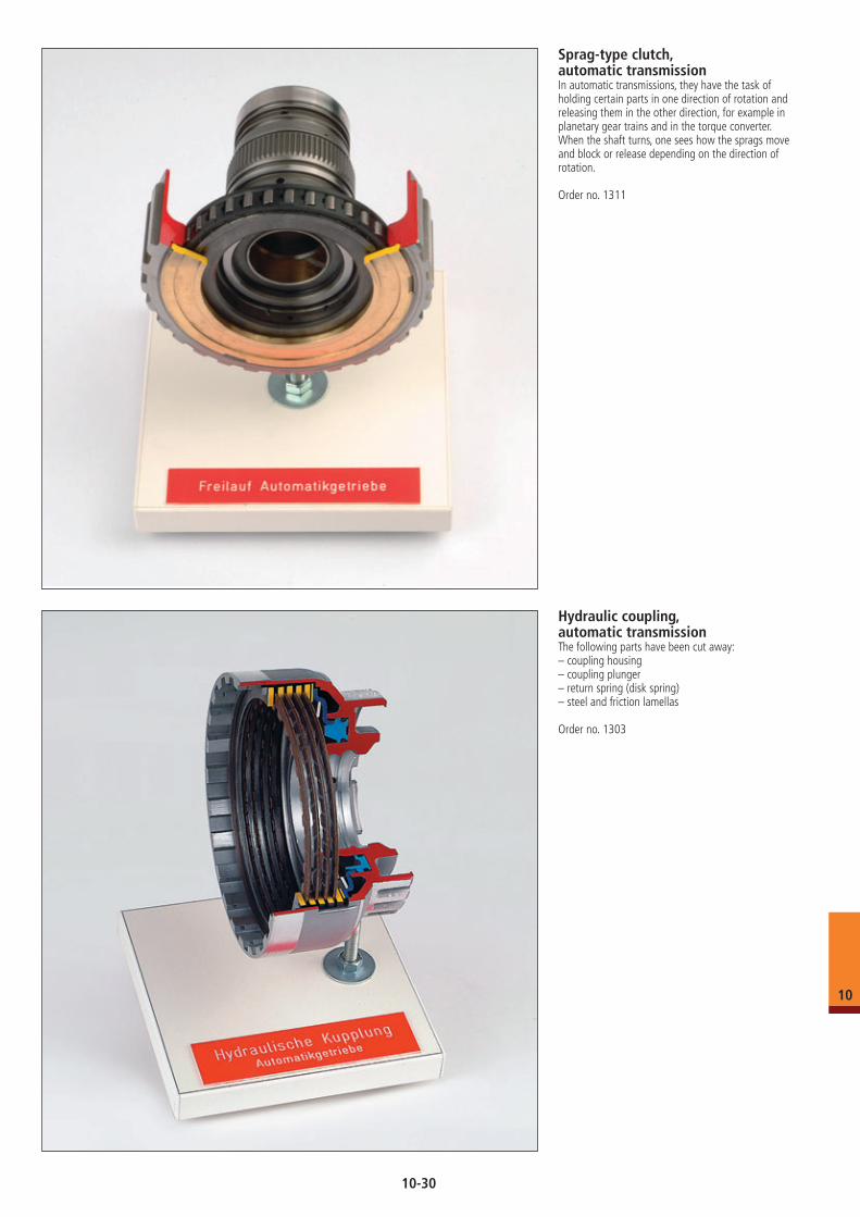
Hydraulic coupling, automatic transmissionThe following parts have been cut away: – coupling housing– coupling plunger– return spring (disk spring)– steel and friction lamellas
Order no. 1303
Sprag-type clutch, automatic transmissionIn automatic transmissions, they have the task of holding certain parts in one direction of rotation and releasing them in the other direction, for example in planetary gear trains and in the torque converter.When the shaft turns, one sees how the sprags move and block or release depending on the direction of rotation.
Order no. 1311
10
10-30
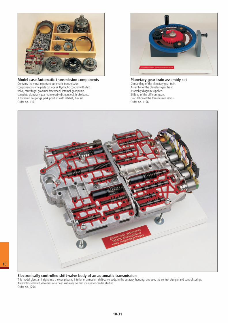
Model case Automatic transmission componentsContains the most important automatic transmission components (some parts cut open). Hydraulic control with shift valve, centrifugal governor, freewheel, internal gear pump,complete planetary gear train (easily dismantled), brake band, 2 hydraulic couplings, park position with ratchet, disk set.Order no. 1161
Planetary gear train assembly setDismantling of the planetary gear train.Assembly of the planetary gear train.Assembly diagram supplied.Shifting of the different gears.Calculation of the transmission ratios.Order no. 1156
Electronically controlled shift-valve body of an automatic transmissionThis model gives an insight into the complicated interior of a modern shift-valve body. In the cutaway housing, one sees the control plunger and control springs. An electro-solenoid valve has also been cut away so that its interior can be studied.Order no. 1294
10
10-31
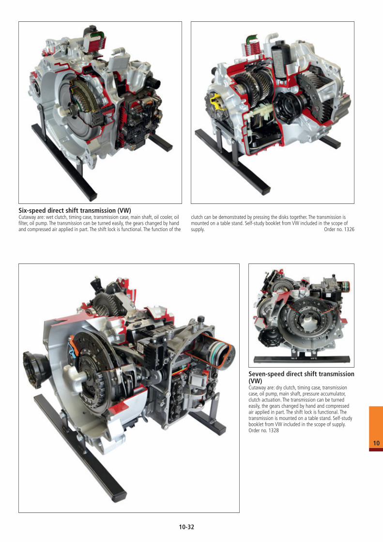
Six-speed direct shift transmission (VW)Cutaway are: wet clutch, timing case, transmission case, main shaft, oil cooler, oil filter, oil pump. The transmission can be turned easily, the gears changed by hand and compressed air applied in part. The shift lock is functional. The function of the
clutch can be demonstrated by pressing the disks together. The transmission is mounted on a table stand. Self-study booklet from VW included in the scope of supply. Order no. 1326
Seven-speed direct shift transmission (VW)Cutaway are: dry clutch, timing case, transmission case, oil pump, main shaft, pressure accumulator, clutch actuation. The transmission can be turned easily, the gears changed by hand and compressed air applied in part. The shift lock is functional. The transmission is mounted on a table stand. Self-study booklet from VW included in the scope of supply. Order no. 1328
10
10-32
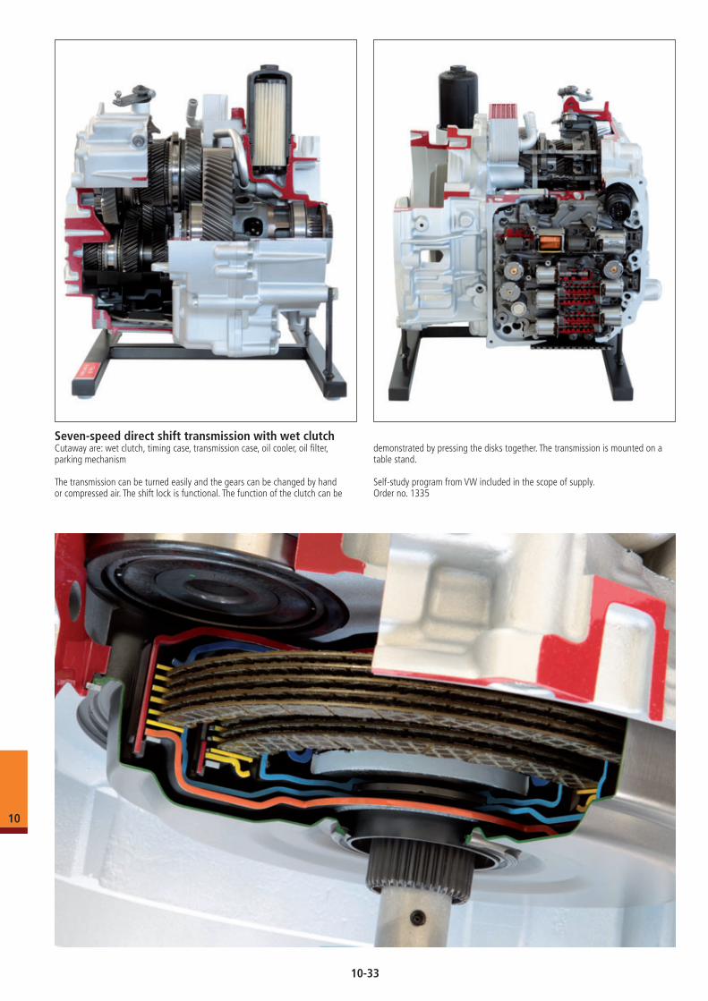
Seven-speed direct shift transmission with wet clutchCutaway are: wet clutch, timing case, transmission case, oil cooler, oil filter, parking mechanism
The transmission can be turned easily and the gears can be changed by hand or compressed air. The shift lock is functional. The function of the clutch can be
demonstrated by pressing the disks together. The transmission is mounted on a table stand.
Self-study program from VW included in the scope of supply. Order no. 1335
10
10-33
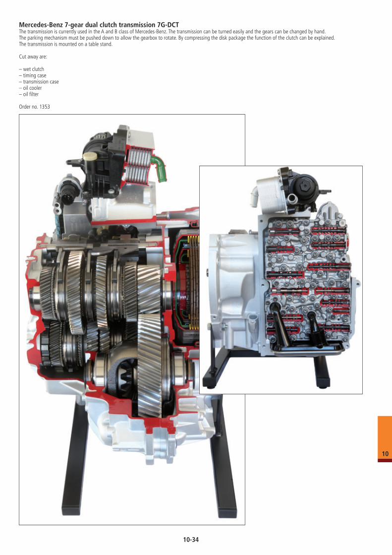
Mercedes-Benz 7-gear dual clutch transmission 7G-DCTThe transmission is currently used in the A and B class of Mercedes-Benz. The transmission can be turned easily and the gears can be changed by hand. The parking mechanism must be pushed down to allow the gearbox to rotate. By compressing the disk package the function of the clutch can be explained. The transmission is mounted on a table stand.
Cut away are:
– wet clutch– timing case– transmission case– oil cooler– oil filter
Order no. 1353
10
10-34
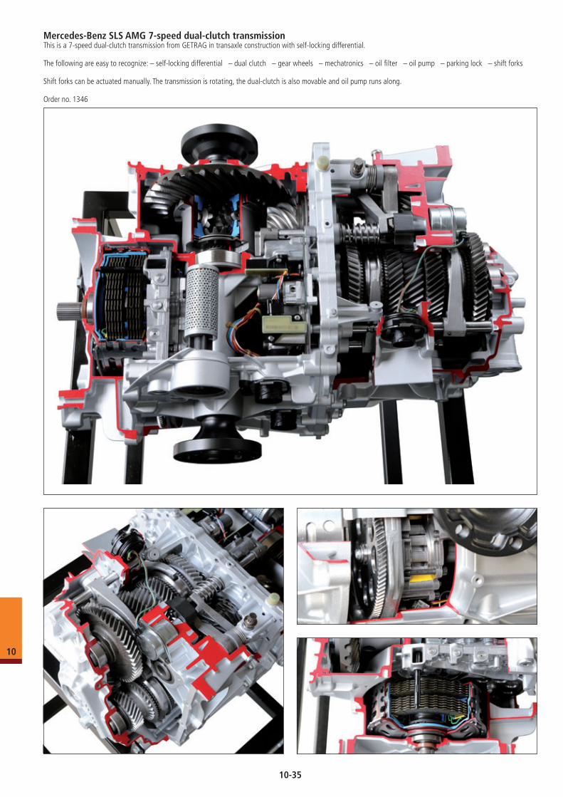
Mercedes-Benz SLS AMG 7-speed dual-clutch transmissionThis is a 7-speed dual-clutch transmission from GETRAG in transaxle construction with self-locking differential.
The following are easy to recognize: – self-locking differential – dual clutch – gear wheels – mechatronics – oil filter – oil pump – parking lock – shift forks
Shift forks can be actuated manually. The transmission is rotating, the dual-clutch is also movable and oil pump runs along.
Order no. 1346
10
10-35
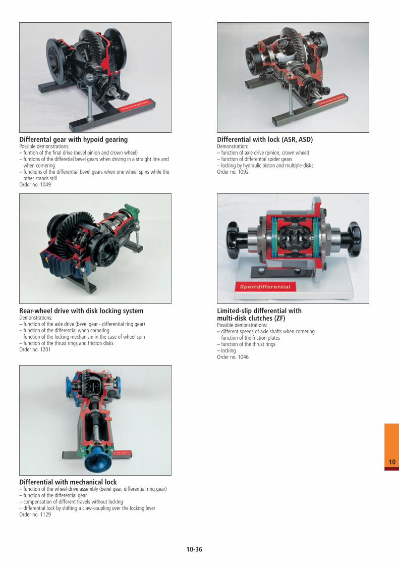
Differental gear with hypoid gearingPossible demonstrations: – funtion of the final drive (bevel pinion and crown wheel)– funtions of the differetial bevel gears when driving in a straight line and
when cornering– functions of the differential bevel gears when one wheel spins while the
other stands stillOrder no. 1049
Differential with lock (ASR, ASD)Demonstration:– function of axle drive (pinion, crown wheel)– function of differential spider gears– locking by hydraulic piston and multiple-disksOrder no. 1092
Rear-wheel drive with disk locking systemDemonstrations:– function of the axle drive (bevel gear - differential ring gear)– function of the differential when cornering– function of the locking mechanism in the case of wheel spin– function of the thrust rings and friction disksOrder no. 1201
Differential with mechanical lock– function of the wheel-drive assembly (bevel gear, differential ring gear)– function of the differential gear– compensation of different travels without locking– differential lock by shifting a claw-coupling over the locking leverOrder no. 1129
Limited-slip differential with multi-disk clutches (ZF)Possible demonstrations: – different speeds of axle shafts when cornering– function of the friction plates– function of the thrust rings– lockingOrder no. 1046
10
10-36
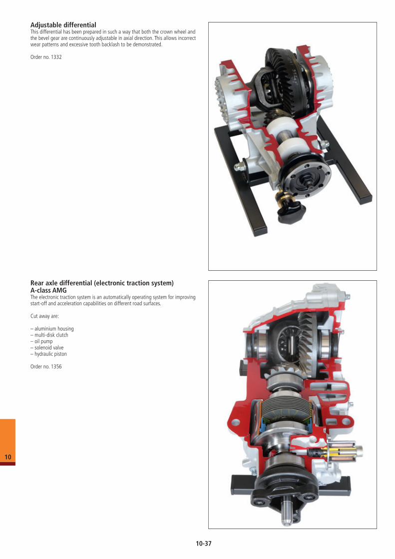
Rear axle differential (electronic traction system) A-class AMGThe electronic traction system is an automatically operating system for improving start-off and acceleration capabilities on different road surfaces. Cut away are: – aluminium housing– multi-disk clutch– oil pump– solenoid valve– hydraulic piston
Order no. 1356
Adjustable differential This differential has been prepared in such a way that both the crown wheel and the bevel gear are continuously adjustable in axial direction. This allows incorrect wear patterns and excessive tooth backlash to be demonstrated.
Order no. 1332
10
10-37
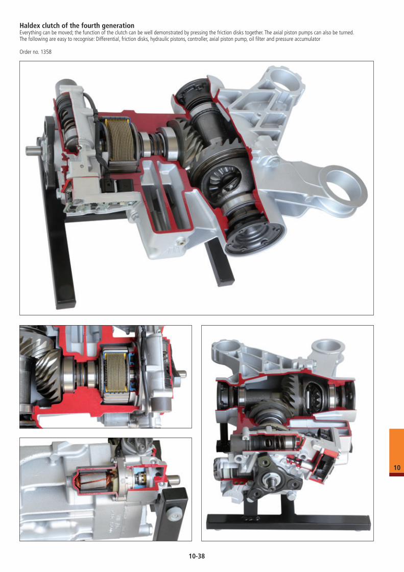
Haldex clutch of the fourth generationEverything can be moved; the function of the clutch can be well demonstrated by pressing the friction disks together. The axial piston pumps can also be turned. The following are easy to recognise: Differential, friction disks, hydraulic pistons, controller, axial piston pump, oil filter and pressure accumulator
Order no. 1358
10
10-38
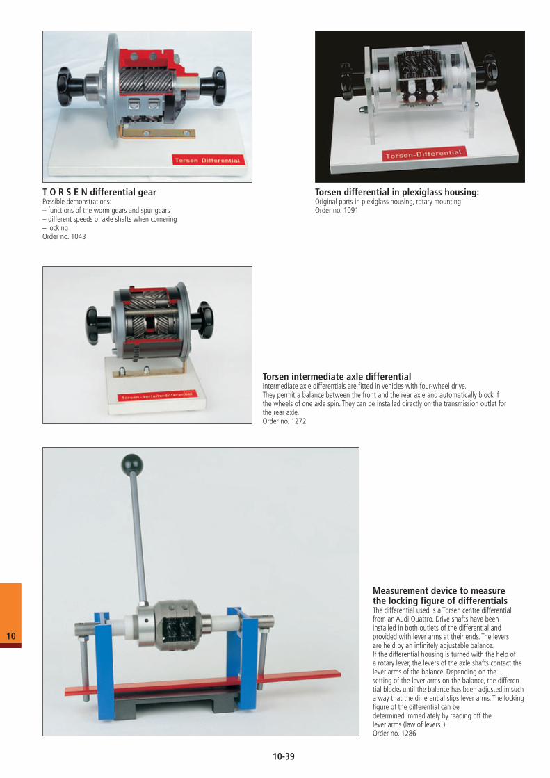
T O R S E N differential gearPossible demonstrations: – functions of the worm gears and spur gears– different speeds of axle shafts when cornering– locking Order no. 1043
Torsen differential in plexiglass housing:Original parts in plexiglass housing, rotary mountingOrder no. 1091
Torsen intermediate axle differentialIntermediate axle differentials are fitted in vehicles with four-wheel drive. They permit a balance between the front and the rear axle and automatically block if the wheels of one axle spin. They can be installed directly on the transmission outlet for the rear axle.Order no. 1272
Measurement device to measure the locking figure of differentialsThe differential used is a Torsen centre differential from an Audi Quattro. Drive shafts have been installed in both outlets of the differential and provided with lever arms at their ends. The levers are held by an infinitely adjustable balance.If the differential housing is turned with the help of a rotary lever, the levers of the axle shafts contact the lever arms of the balance. Depending on the setting of the lever arms on the balance, the differen-tial blocks until the balance has been adjusted in such a way that the differential slips lever arms. The locking figure of the differential can be determined immediately by reading off the lever arms (law of levers!).Order no. 1286
10
10-39
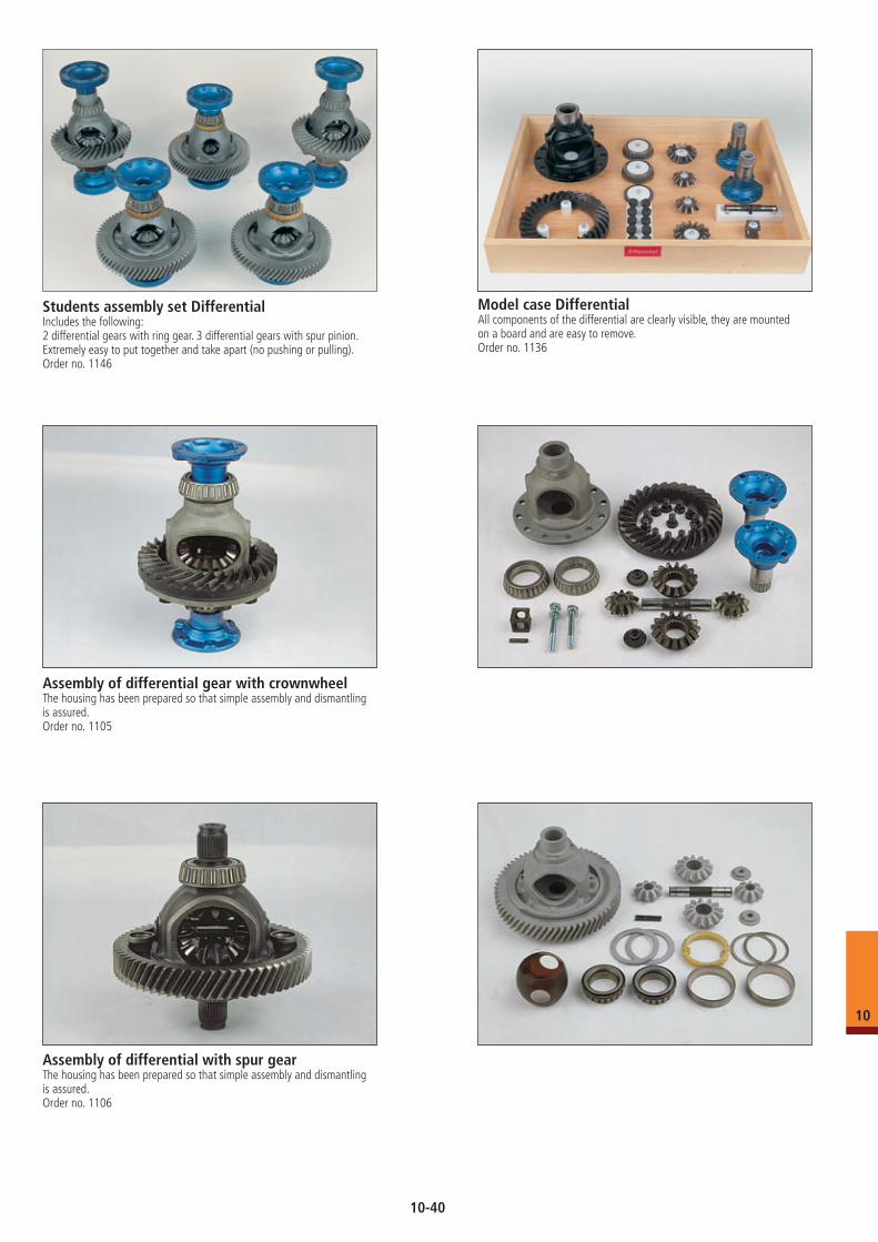
Assembly of differential gear with crownwheelThe housing has been prepared so that simple assembly and dismantling is assured.Order no. 1105
Students assembly set DifferentialIncludes the following:2 differential gears with ring gear. 3 differential gears with spur pinion.Extremely easy to put together and take apart (no pushing or pulling).Order no. 1146
Assembly of differential with spur gearThe housing has been prepared so that simple assembly and dismantling is assured.Order no. 1106
Model case DifferentialAll components of the differential are clearly visible, they are mounted on a board and are easy to remove.Order no. 1136
10
10-40
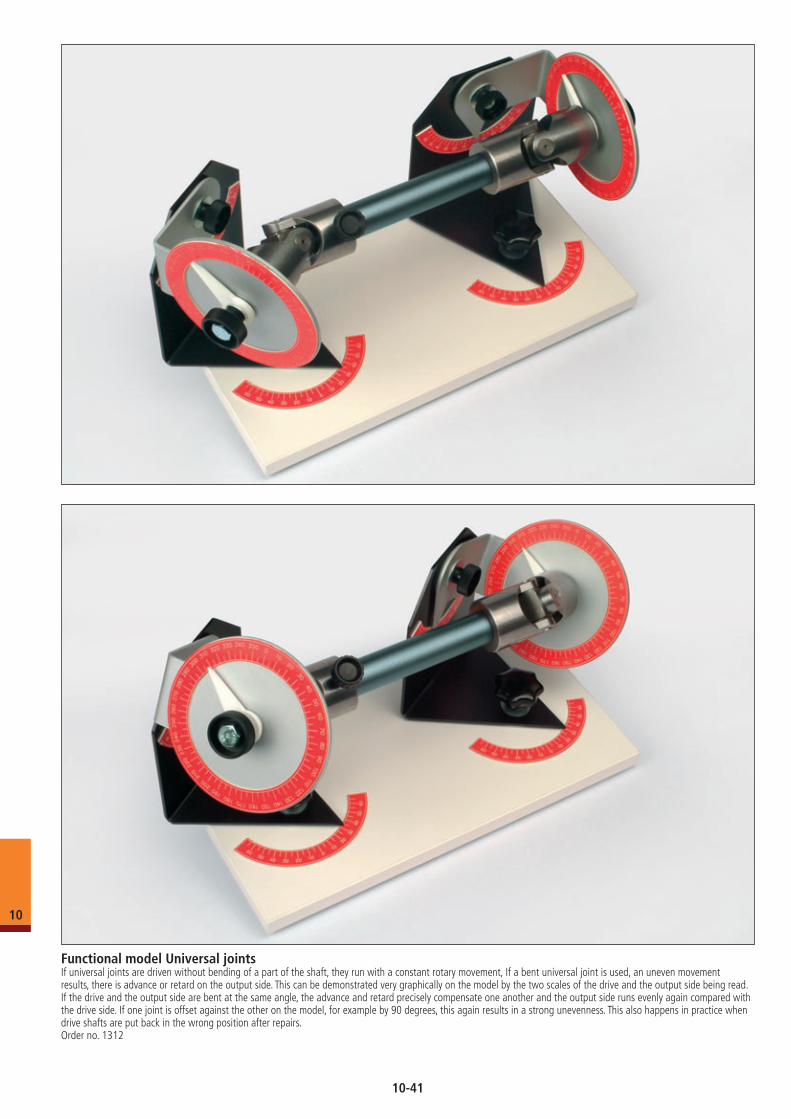
Functional model Universal jointsIf universal joints are driven without bending of a part of the shaft, they run with a constant rotary movement, If a bent universal joint is used, an uneven movement results, there is advance or retard on the output side. This can be demonstrated very graphically on the model by the two scales of the drive and the output side being read. If the drive and the output side are bent at the same angle, the advance and retard precisely compensate one another and the output side runs evenly again compared with the drive side. If one joint is offset against the other on the model, for example by 90 degrees, this again results in a strong unevenness. This also happens in practice when drive shafts are put back in the wrong position after repairs.Order no. 1312
10
10-41
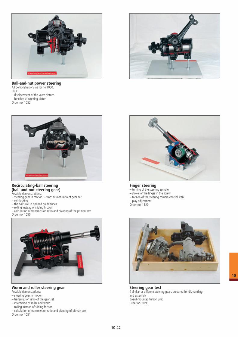
Ball-and-nut power steeringAll demonstrations as for no.1050.Plus:– displacement of the valve pistons– function of working pistonOrder no. 1052
Recirculating-ball steering (ball-and-nut steering gear)Possible demonstrations: – steering gear in motion – transmission ratio of gear set– self-locking– the balls roll in opened guide tubes– rolling instead of sliding friction– calculation of transmission ratio and pivoting of the pitman armOrder no. 1050
Finger steering– turning of the steering spindle– stroke of the finger in the screw– torsion of the steering column control stalk– play adjustmentOrder no. 1120
Worm and roller steering gearPossible demonstations: – steering gear in motion– transmission ratio of the gear set– interaction of roller and worm– rolling instead of sliding friction– calculation of transmission ratio and pivoting of pitman armOrder no. 1051
Steering gear test4 similar or different steering gears prepared for dismantling and assemblyBoard-mounted tuition unitOrder no. 1098
10
10-42
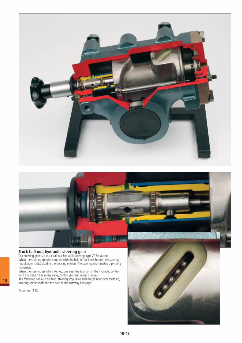
Truck ball nut, hydraulic steering gearOur steering gear is a truck ball nut hydraulic steering, type ZF Servocom.When the steering spindle is turned with the help of the cross button, the steering nut plunger is displaced in the housing cylinder. The steering shaft makes a pivoting movement.When the steering spindle is turned, one sees the function of the hydraulic control with the torsion bar, rotary valve, control jack and radial grooves.The following can also be seen: steering stop valve, ball nut plunger with toothing, steering-sector shaft and the balls in the cutaway ball cage.
Order no. 1313
10
10-43
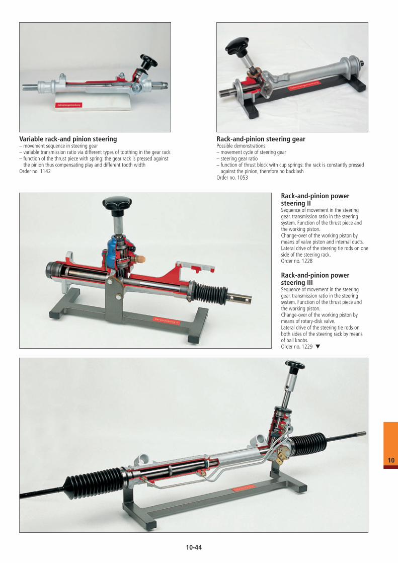
Variable rack-and pinion steering– movement sequence in steering gear– variable transmission ratio via different types of toothing in the gear rack– function of the thrust piece with spring: the gear rack is pressed against
the pinion thus compensating play and different tooth widthOrder no. 1142
Rack-and-pinion steering gearPossible demonstrations: – movement cycle of steering gear – steering gear ratio– function of thrust block with cup springs: the rack is constantly pressed
against the pinion, therefore no backlashOrder no. 1053
Rack-and-pinion power steering IISequence of movement in the steering gear, transmission ratio in the steering system. Function of the thrust piece and the working piston.Change-over of the working piston by means of valve piston and internal ducts.Lateral drive of the steering tie rods on one side of the steering rack.Order no. 1228
Rack-and-pinion power steering IIISequence of movement in the steering gear, transmission ratio in the steering system. Function of the thrust piece and the working piston.Change-over of the working piston by means of rotary-disk valve.Lateral drive of the steering tie rods on both sides of the steering rack by means of ball knobs.Order no. 1229 ▼
10
10-44
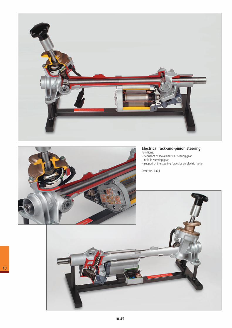
Electrical rack-and-pinion steeringFunctions:– sequence of movements in steering gear– ratio in steering gear– support of the steering forces by an electric motor
Order no. 1301
10
10-45
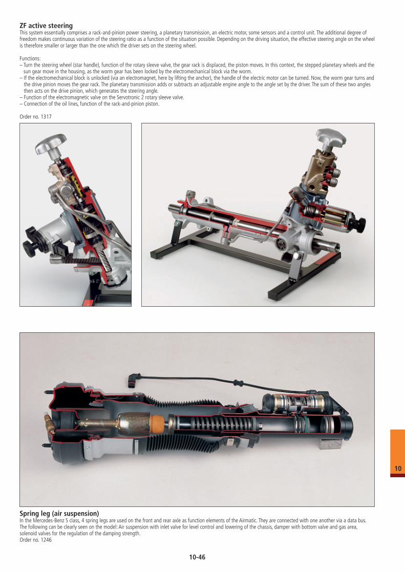
ZF active steeringThis system essentially comprises a rack-and-pinion power steering, a planetary transmission, an electric motor, some sensors and a control unit. The additional degree of freedom makes continuous variation of the steering ratio as a function of the situation possible. Depending on the driving situation, the effective steering angle on the wheel is therefore smaller or larger than the one which the driver sets on the steering wheel.
Functions:– Turn the steering wheel (star handle), function of the rotary sleeve valve, the gear rack is displaced, the piston moves. In this context, the stepped planetary wheels and the
sun gear move in the housing, as the worm gear has been locked by the electromechanical block via the worm.– If the electromechanical block is unlocked (via an electromagnet, here by lifting the anchor), the handle of the electric motor can be turned. Now, the worm gear turns and
the drive pinion moves the gear rack. The planetary transmission adds or subtracts an adjustable engine angle to the angle set by the driver. The sum of these two angles then acts on the drive pinion, which generates the steering angle.
– Function of the electromagnetic valve on the Servotronic 2 rotary sleeve valve.– Connection of the oil lines, function of the rack-and-pinion piston.
Order no. 1317
Spring leg (air suspension)In the Mercedes-Benz S class, 4 spring legs are used on the front and rear axle as function elements of the Airmatic. They are connected with one another via a data bus. The following can be clearly seen on the model: Air suspension with inlet valve for level control and lowering of the chassis, damper with bottom valve and gas area, solenoid valves for the regulation of the damping strength.Order no. 1246
10
10-46
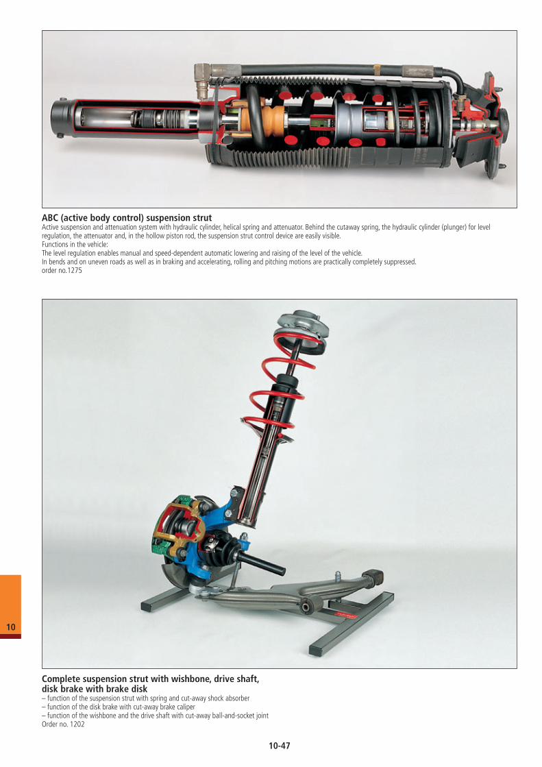
ABC (active body control) suspension strutActive suspension and attenuation system with hydraulic cylinder, helical spring and attenuator. Behind the cutaway spring, the hydraulic cylinder (plunger) for level regulation, the attenuator and, in the hollow piston rod, the suspension strut control device are easily visible.Functions in the vehicle:The level regulation enables manual and speed-dependent automatic lowering and raising of the level of the vehicle.In bends and on uneven roads as well as in braking and accelerating, rolling and pitching motions are practically completely suppressed.order no.1275
Complete suspension strut with wishbone, drive shaft, disk brake with brake disk– function of the suspension strut with spring and cut-away shock absorber– function of the disk brake with cut-away brake caliper– function of the wishbone and the drive shaft with cut-away ball-and-socket joint Order no. 1202
10
10-47
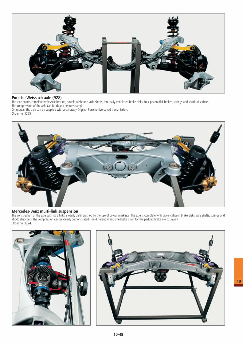
Porsche Weissach axle (928)The axle comes complete with: Axle bracket, double wishbone, axle shafts, internally-ventilated brake disks, four-piston disk brakes, springs and shock absorbers. The compression of the axle can be clearly demonstrated.On request the axle can be supplied with a cut-away Original Porsche five-speed transmission.Order no. 1225
Mercedes-Benz multi-link suspensionThe construction of the axle with its 5 links is easily distinguished by the use of colour markings. The axle is complete with brake calipers, brake disks, axle shafts, springs and shock absorbers. The compression can be clearly demonstrated. The differential and one brake drum for the parking brake are cut away.Order no. 1224
10
10-48
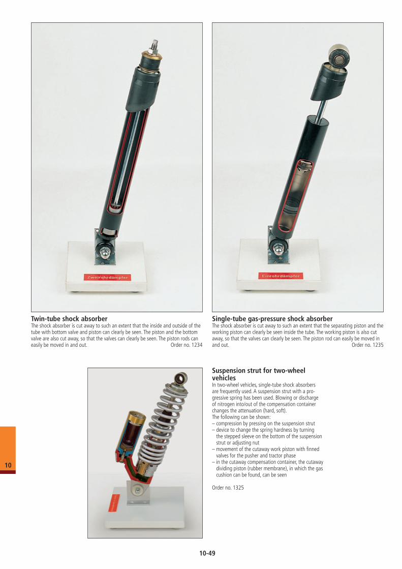
Twin-tube shock absorberThe shock absorber is cut away to such an extent that the inside and outside of the tube with bottom valve and piston can clearly be seen. The piston and the bottom valve are also cut away, so that the valves can clearly be seen. The piston rods can easily be moved in and out. Order no. 1234
Single-tube gas-pressure shock absorberThe shock absorber is cut away to such an extent that the separating piston and the working piston can clearly be seen inside the tube. The working piston is also cut away, so that the valves can clearly be seen. The piston rod can easily be moved in and out. Order no. 1235
Suspension strut for two-wheel vehiclesIn two-wheel vehicles, single-tube shock absorbers are frequently used. A suspension strut with a pro-gressive spring has been used. Blowing or discharge of nitrogen into/out of the compensation container changes the attenuation (hard, soft).The following can be shown:– compression by pressing on the suspension strut– device to change the spring hardness by turning
the stepped sleeve on the bottom of the suspension strut or adjusting nut
– movement of the cutaway work piston with finned valves for the pusher and tractor phase
– in the cutaway compensation container, the cutaway dividing piston (rubber membrane), in which the gas cushion can be found, can be seen
Order no. 1325
10
10-49
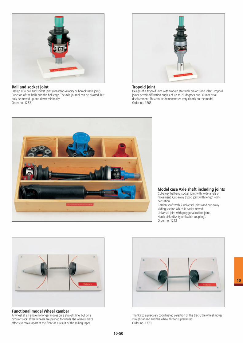
Ball and socket jointDesign of a ball and socket joint (constant-velocity or homokinetic joint).Function of the balls and the ball cage. The axle journal can be pivoted, but only be moved up and down minimally.Order no. 1262
Tropoid jointDesign of a tropoid joint with tropoid star with pinions and idlers. Tropoid joints permit diffraction angles of up to 20 degrees and 30 mm axial displacement. This can be demonstrated very clearly on the model.Order no. 1263
Model case Axle shaft including jointsCut-away ball-and-socket joint with wide angle of movement. Cut-away tripod joint with length com-pensation.Cardan shaft with 2 universal joints and cut-away sliding section which is easily moved.Universal joint with polygonal rubber joint. Hardy disk (disk-type flexible coupling).Order no. 1213
Functional model Wheel camberA wheel at an angle no longer moves on a straight line, but on a circular track. If the wheels are pushed forwards, the wheels make efforts to move apart at the front as a result of the rolling taper.
Thanks to a precisely coordinated selection of the track, the wheel moves straight ahead and the wheel flutter is prevented.Order no. 1270
10
10-50
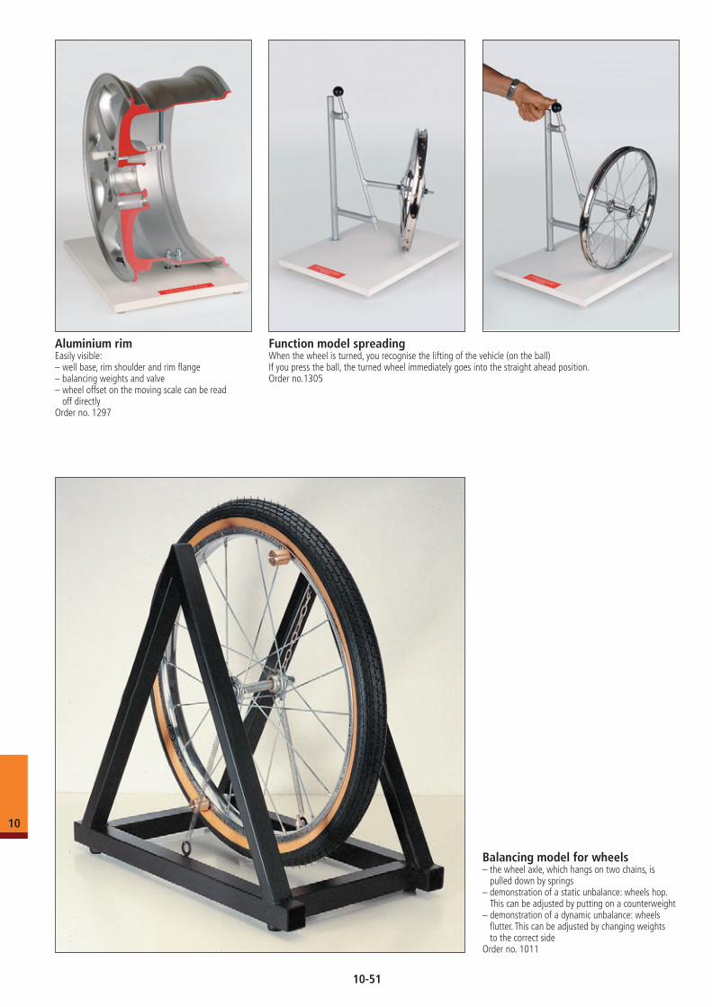
Balancing model for wheels– the wheel axle, which hangs on two chains, is
pulled down by springs– demonstration of a static unbalance: wheels hop.
This can be adjusted by putting on a counterweight– demonstration of a dynamic unbalance: wheels
flutter. This can be adjusted by changing weights to the correct side
Order no. 1011
Aluminium rim Easily visible:– well base, rim shoulder and rim flange– balancing weights and valve– wheel offset on the moving scale can be read
off directlyOrder no. 1297
Function model spreading When the wheel is turned, you recognise the lifting of the vehicle (on the ball)If you press the ball, the turned wheel immediately goes into the straight ahead position.Order no.1305
10
10-51
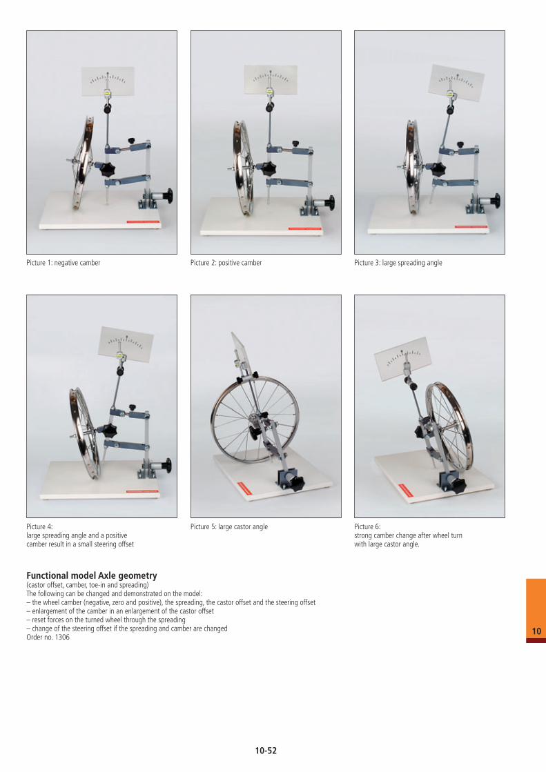
Picture 1: negative camber
Picture 2: positive camber Picture 3: large spreading angle
Picture 4: large spreading angle and a positivecamber result in a small steering offset
Functional model Axle geometry (castor offset, camber, toe-in and spreading) The following can be changed and demonstrated on the model:– the wheel camber (negative, zero and positive), the spreading, the castor offset and the steering offset– enlargement of the camber in an enlargement of the castor offset– reset forces on the turned wheel through the spreading– change of the steering offset if the spreading and camber are changedOrder no. 1306
Picture 5: large castor angle Picture 6: strong camber change after wheel turnwith large castor angle.
10
10-52
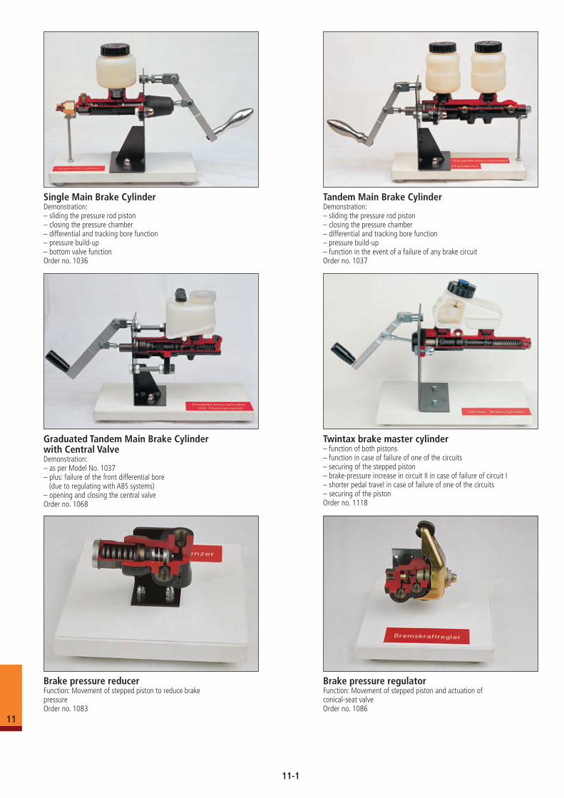
Tandem Main Brake CylinderDemonstration:– sliding the pressure rod piston– closing the pressure chamber– differential and tracking bore function– pressure build-up– function in the event of a failure of any brake circuitOrder no. 1037
Graduated Tandem Main Brake Cylinder with Central ValveDemonstration:– as per Model No. 1037– plus: failure of the front differential bore (due to regulating with ABS systems)– opening and closing the central valveOrder no. 1068
Single Main Brake CylinderDemonstration:– sliding the pressure rod piston– closing the pressure chamber– differential and tracking bore function– pressure build-up– bottom valve functionOrder no. 1036
Brake pressure reducer Function: Movement of stepped piston to reduce brake pressureOrder no. 1083
Brake pressure regulatorFunction: Movement of stepped piston and actuation of conical-seat valveOrder no. 1086
Twintax brake master cylinder– function of both pistons– function in case of failure of one of the circuits– securing of the stepped piston– brake-pressure increase in circuit II in case of failure of circuit I– shorter pedal travel in case of failure of one of the circuits– securing of the pistonOrder no. 1118
11
11-1
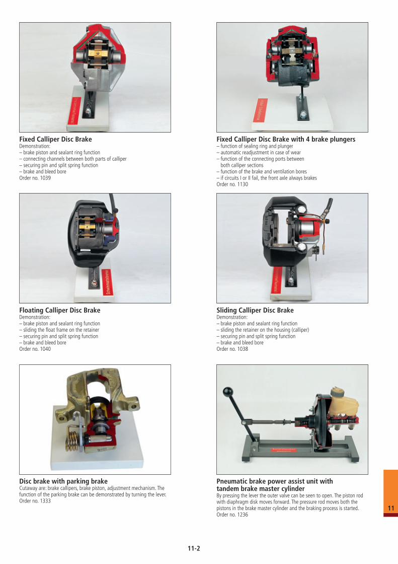
Fixed Calliper Disc BrakeDemonstration:– brake piston and sealant ring function– connecting channels between both parts of calliper– securing pin and split spring function– brake and bleed boreOrder no. 1039
Fixed Calliper Disc Brake with 4 brake plungers– function of sealing ring and plunger– automatic readjustment in case of wear– function of the connecting ports between
both calliper sections– function of the brake and ventilation bores– if circuits I or II fail, the front axle always brakesOrder no. 1130
Sliding Calliper Disc BrakeDemonstration: – brake piston and sealant ring function– sliding the retainer on the housing (calliper)– securing pin and split spring function– brake and bleed bore Order no. 1038
Floating Calliper Disc Brake Demonstration:– brake piston and sealant ring function– sliding the float frame on the retainer– securing pin and split spring function– brake and bleed bore Order no. 1040
Pneumatic brake power assist unit with tandem brake master cylinderBy pressing the lever the outer valve can be seen to open. The piston rod with diaphragm disk moves forward. The pressure rod moves both the pistons in the brake master cylinder and the braking process is started.Order no. 1236
Disc brake with parking brake Cutaway are: brake callipers, brake piston, adjustment mechanism. The function of the parking brake can be demonstrated by turning the lever. Order no. 1333
11
11-2
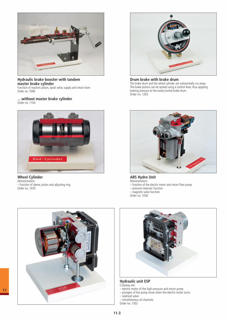
Drum brake with brake drumThe brake drum and the wheel cylinder are substantially cut away. The brake pistons can be spread using a control lever, thus applying braking pressure to the easily-turned brake drum.Order no. 1203
ABS Hydro UnitDemonstration:– function of the electric motor and return flow pump– pressure reservoir function– magnetic valve functionOrder no. 1030
Hydraulic brake booster with tandem master brake cylinderFunction of reaction piston, spool valve, supply and return boreOrder no. 1096
... without master brake cylinderOrder no. 1104
Wheel CylinderDemonstration:– function of sleeve, piston and adjusting ring Order no. 1035
Hydraulic unit ESPCutaway are: – electric motor of the high-pressure and return pump– plungers of the pump move when the electric motor turns– solenoid valve– miscellaneous oil channelsOrder no. 1302
11
11-3
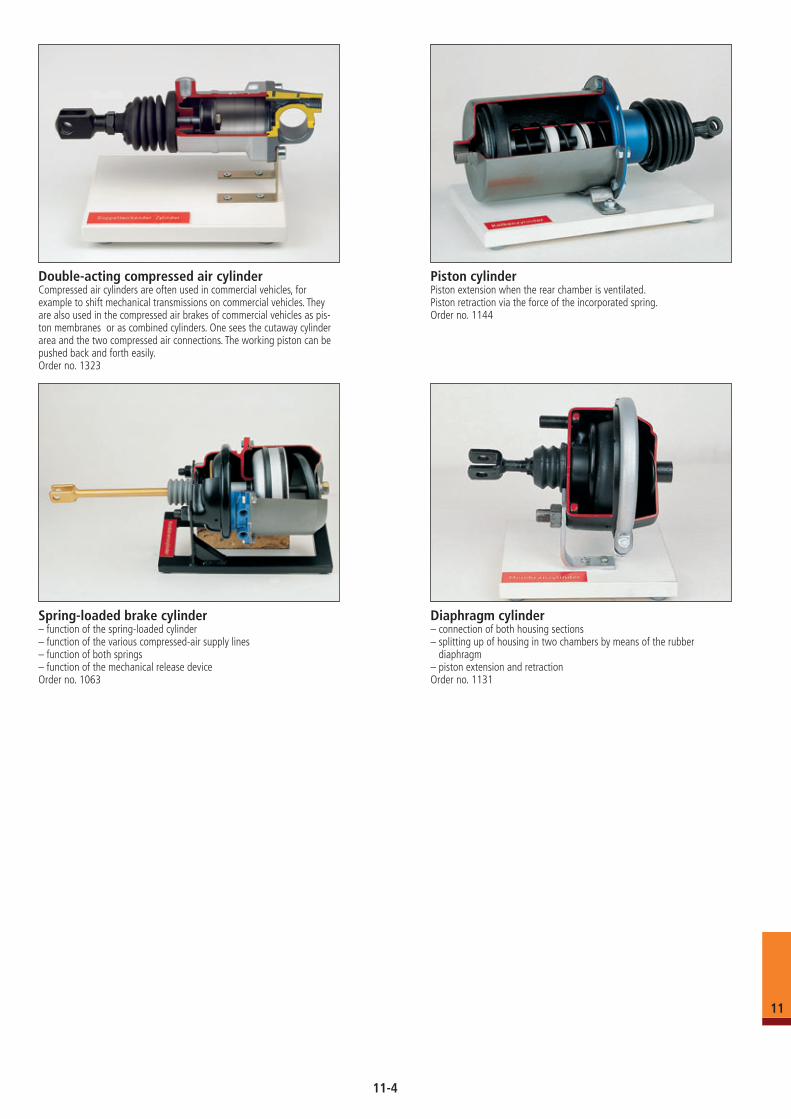
Spring-loaded brake cylinder– function of the spring-loaded cylinder– function of the various compressed-air supply lines– function of both springs– function of the mechanical release deviceOrder no. 1063
Diaphragm cylinder– connection of both housing sections– splitting up of housing in two chambers by means of the rubber
diaphragm– piston extension and retractionOrder no. 1131
Piston cylinderPiston extension when the rear chamber is ventilated.Piston retraction via the force of the incorporated spring.Order no. 1144
Double-acting compressed air cylinderCompressed air cylinders are often used in commercial vehicles, for example to shift mechanical transmissions on commercial vehicles. They are also used in the compressed air brakes of commercial vehicles as pis-ton membranes or as combined cylinders. One sees the cutaway cylinder area and the two compressed air connections. The working piston can be pushed back and forth easily.Order no. 1323
11
11-4
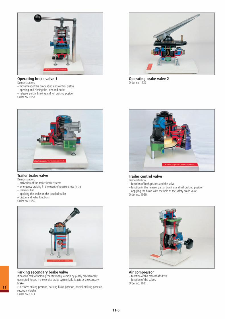
Operating brake valve 1Demonstration: – movement of the graduating and control piston opening and closing the inlet and outlet– release, partial braking and full braking positionOrder no. 1057
Operating brake valve 2Order no. 1137
Trailer brake valveDemonstration: – activation of the trailer brake system– emergency braking in the event of pressure loss in the – reservoir line– applying the brake on the coupled trailer– piston and valve functionsOrder no. 1059
Air compressor– function of the crankshaft drive– function of the valvesOrder no. 1031
Trailer control valveDemonstration:– function of both pistons and the valve– function in the release, partial braking and full braking position– applying the brake with the help of the safety brake valveOrder no. 1060
Parking secondary brake valveIt has the task of holding the stationary vehicle by purely mechanically generated forces. If the service brake system fails, it acts as a secondary brake.Functions: driving position, parking brake position, partial braking position, secondary brake.Order no. 1271
11
11-5
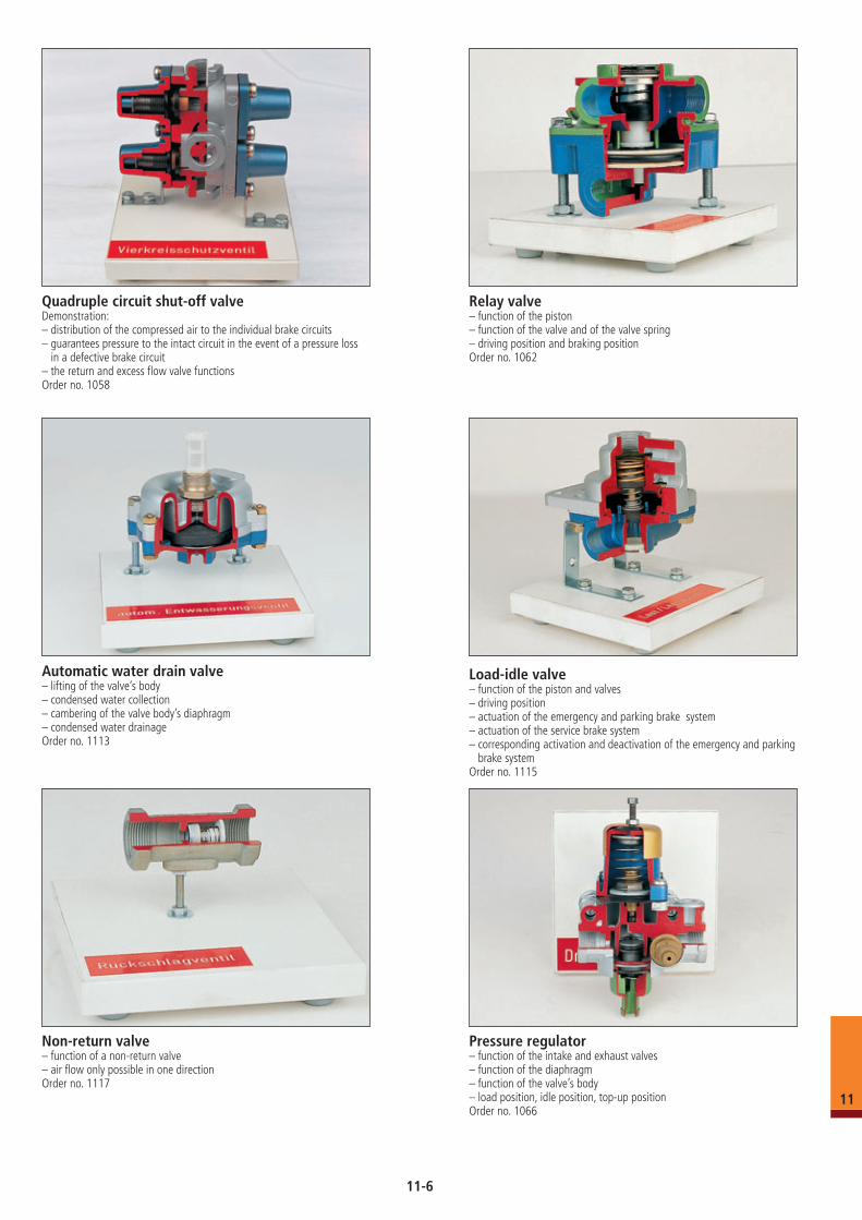
Quadruple circuit shut-off valveDemonstration: – distribution of the compressed air to the individual brake circuits– guarantees pressure to the intact circuit in the event of a pressure loss
in a defective brake circuit– the return and excess flow valve functionsOrder no. 1058
Relay valve– function of the piston– function of the valve and of the valve spring– driving position and braking positionOrder no. 1062
Automatic water drain valve– lifting of the valve’s body– condensed water collection– cambering of the valve body’s diaphragm– condensed water drainageOrder no. 1113
Non-return valve– function of a non-return valve– air flow only possible in one directionOrder no. 1117
Pressure regulator– function of the intake and exhaust valves– function of the diaphragm– function of the valve’s body– load position, idle position, top-up positionOrder no. 1066
Load-idle valve– function of the piston and valves– driving position– actuation of the emergency and parking brake system – actuation of the service brake system– corresponding activation and deactivation of the emergency and parking
brake systemOrder no. 1115
11
11-6
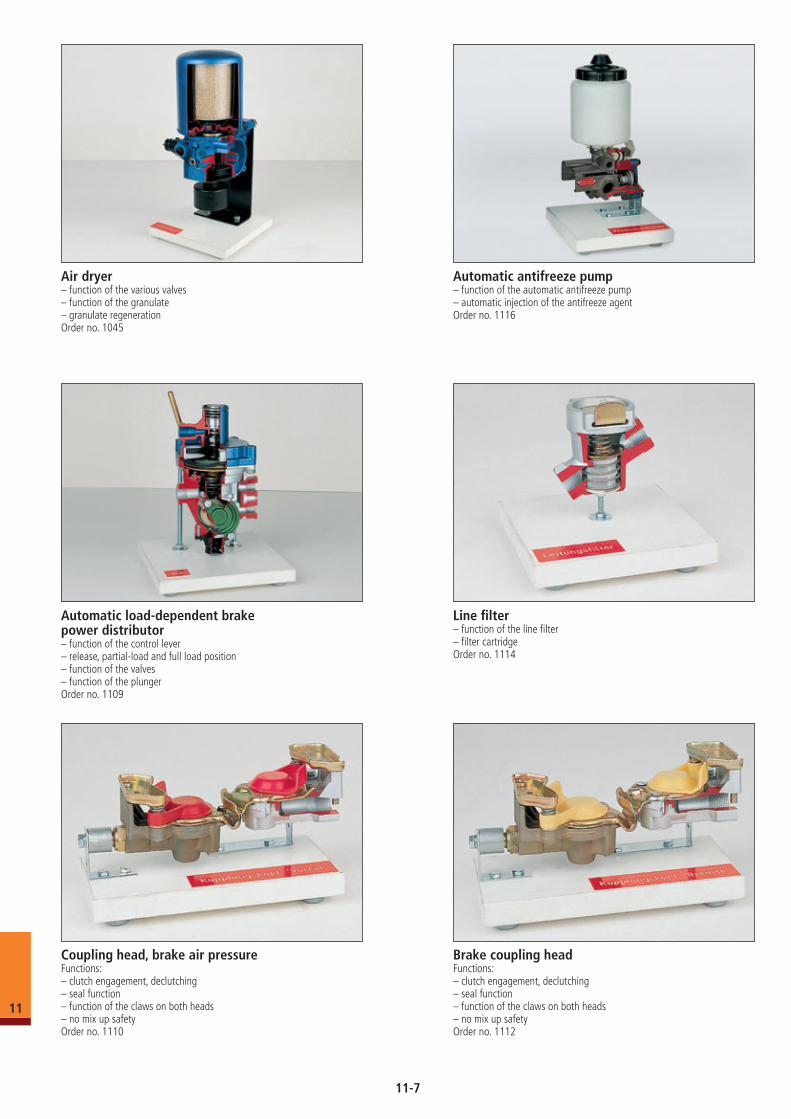
Air dryer– function of the various valves– function of the granulate– granulate regenerationOrder no. 1045
Coupling head, brake air pressureFunctions:– clutch engagement, declutching– seal function– function of the claws on both heads– no mix up safetyOrder no. 1110
Line filter– function of the line filter– filter cartridgeOrder no. 1114
Automatic antifreeze pump– function of the automatic antifreeze pump– automatic injection of the antifreeze agentOrder no. 1116
Brake coupling headFunctions: – clutch engagement, declutching– seal function– function of the claws on both heads– no mix up safetyOrder no. 1112
Automatic load-dependent brake power distributor– function of the control lever– release, partial-load and full load position– function of the valves– function of the plungerOrder no. 1109
11
11-7
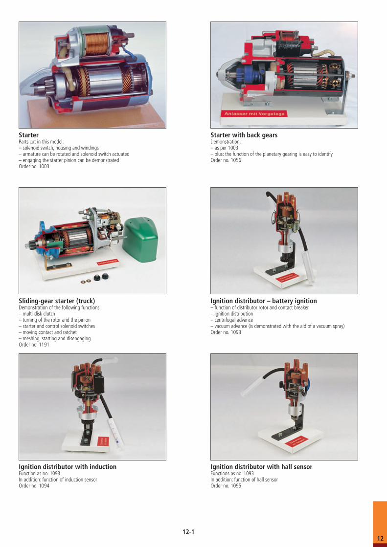
StarterParts cut in this model: – solenoid switch, housing and windings– armature can be rotated and solenoid switch actuated– engaging the starter pinion can be demonstratedOrder no. 1003
Starter with back gears Demonstration:– as per 1003– plus: the function of the planetary gearing is easy to identify Order no. 1056
Sliding-gear starter (truck)Demonstration of the following functions:– multi-disk clutch– turning of the rotor and the pinion– starter and control solenoid switches– moving contact and ratchet– meshing, starting and disengagingOrder no. 1191
Ignition distributor with inductionFunction as no. 1093In addition: function of induction sensorOrder no. 1094
Ignition distributor with hall sensorFunctions as no. 1093In addition: function of hall sensorOrder no. 1095
Ignition distributor – battery ignition– function of distributor rotor and contact breaker– ignition distribution– centrifugal advance– vacuum advance (is demonstrated with the aid of a vacuum spray)Order no. 1093
12-112
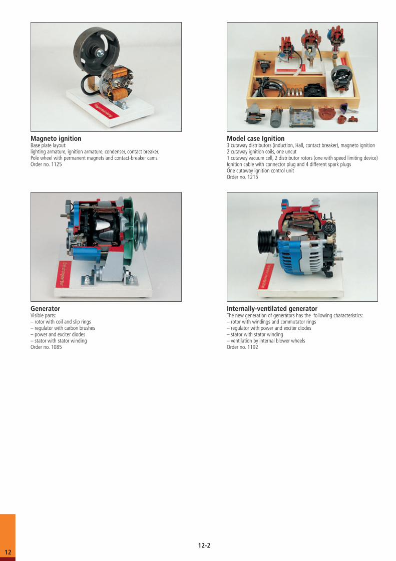
Magneto ignitionBase plate layout:lighting armature, ignition armature, condenser, contact breaker.Pole wheel with permanent magnets and contact-breaker cams.Order no. 1125
Model case Ignition3 cutaway distributors (induction, Hall, contact breaker), magneto ignition2 cutaway ignition coils, one uncut1 cutaway vacuum cell, 2 distributor rotors (one with speed limiting device)Ignition cable with connector plug and 4 different spark plugsOne cutaway ignition control unitOrder no. 1215
Internally-ventilated generatorThe new generation of generators has the following characteristics:– rotor with windings and commutator rings– regulator with power and exciter diodes– stator with stator winding– ventilation by internal blower wheelsOrder no. 1192
GeneratorVisible parts:– rotor with coil and slip rings– regulator with carbon brushes– power and exciter diodes– stator with stator windingOrder no. 1085
12-212
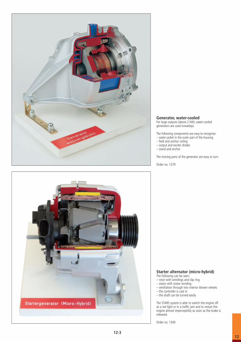
Generator, water-cooledFor large outputs (above 2 kW), water-cooled generators are used nowadays.
The following components are easy to recognise:– water jacket in the outer part of the housing– field and anchor coiling– output and exciter diodes– stand and anchor
The moving parts of the generator are easy to turn.
Order no. 1279
Starter alternator (micro-hybrid)The following can be seen: – rotor with windings and slip ring– stator with stator winding– ventilation through two interior blower wheels– the controller is cast in– the shaft can be turned easily
The STARS system is able to switch the engine off at a red light or in a traffic jam and to restart the engine almost imperceptibly as soon as the brake is released.
Order no. 1340
12-312
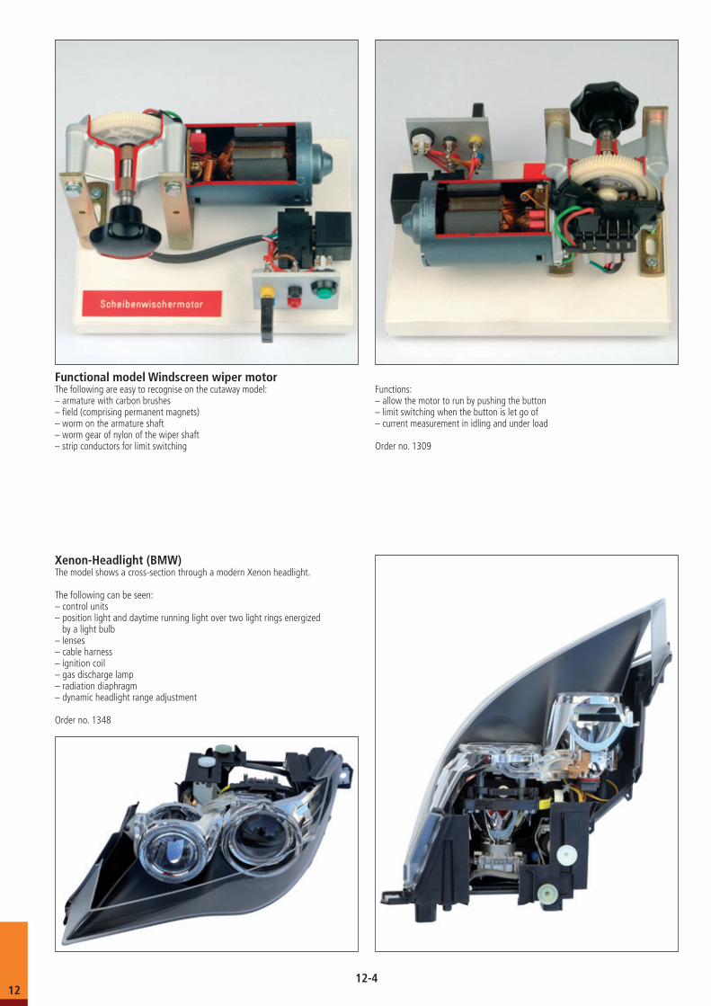
Functional model Windscreen wiper motorThe following are easy to recognise on the cutaway model:– armature with carbon brushes– field (comprising permanent magnets)– worm on the armature shaft– worm gear of nylon of the wiper shaft– strip conductors for limit switching
Functions: – allow the motor to run by pushing the button– limit switching when the button is let go of– current measurement in idling and under load
Order no. 1309
Xenon-Headlight (BMW)The model shows a cross-section through a modern Xenon headlight.
The following can be seen: – control units– position light and daytime running light over two light rings energized by a light bulb– lenses– cable harness– ignition coil– gas discharge lamp– radiation diaphragm– dynamic headlight range adjustment
Order no. 1348
12-412
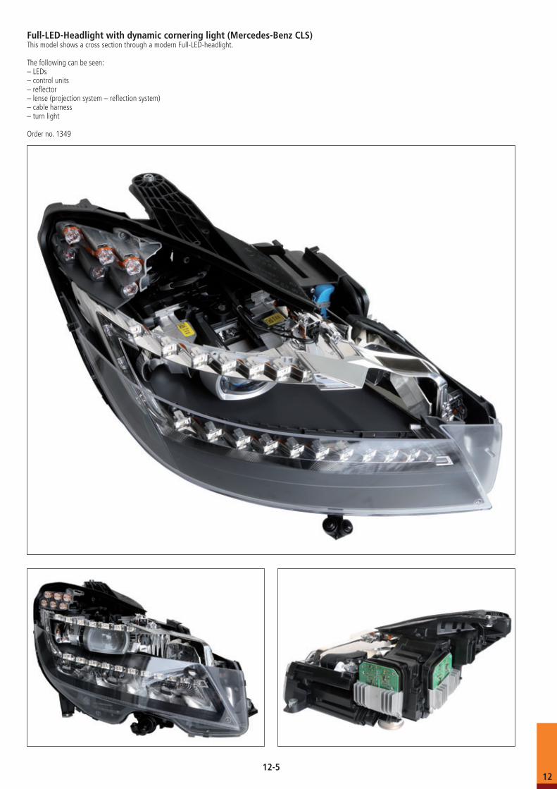
Full-LED-Headlight with dynamic cornering light (Mercedes-Benz CLS)This model shows a cross section through a modern Full-LED-headlight.
The following can be seen: – LEDs– control units– reflector– lense (projection system – reflection system)– cable harness– turn light
Order no. 1349
12-512
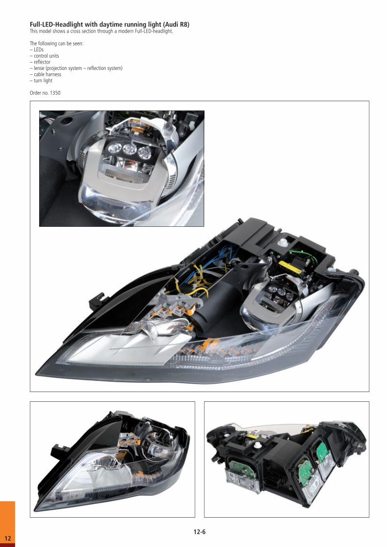
Full-LED-Headlight with daytime running light (Audi R8)This model shows a cross section through a modern Full-LED-headlight.
The following can be seen:– LEDs– control units– reflector– lense (projection system – reflection system)– cable harness– turn light
Order no. 1350
12-612
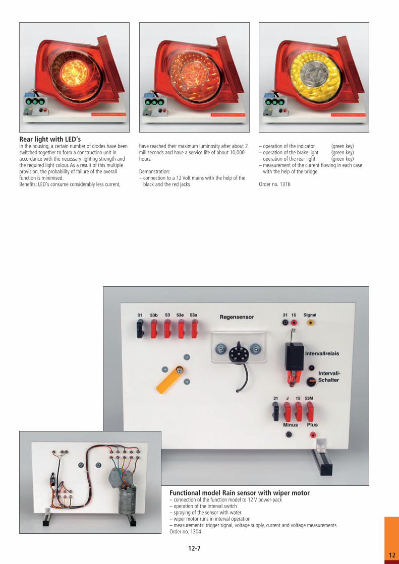
Rear light with LED‘sIn the housing, a certain number of diodes have been switched together to form a construction unit in accordance with the necessary lighting strength and the required light colour. As a result of this multiple provision, the probability of failure of the overall function is minimised.Benefits: LED‘s consume considerably less current,
have reached their maximum luminosity after about 2 milliseconds and have a service life of about 10,000 hours.
Demonstration:– connection to a 12 Volt mains with the help of the
black and the red jacks
– operation of the indicator (green key)– operation of the brake light (green key)– operation of the rear light (green key)– measurement of the current flowing in each case
with the help of the bridge
Order no. 1316
Functional model Rain sensor with wiper motor – connection of the function model to 12 V power-pack– operation of the interval switch– spraying of the sensor with water– wiper motor runs in interval operation– measurements: trigger signal, voltage supply, current and voltage measurementsOrder no. 1304
12-712
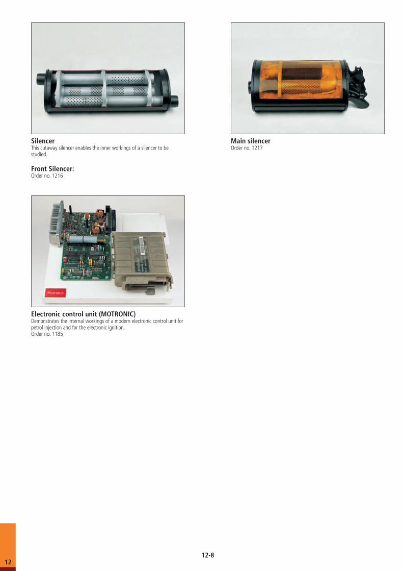
Electronic control unit (MOTRONIC)Demonstrates the internal workings of a modern electronic control unit for petrol injection and for the electronic ignition.Order no. 1185
SilencerThis cutaway silencer enables the inner workings of a silencer to be studied.
Front Silencer:Order no. 1216
Main silencerOrder no. 1217
12-812


