Embed Size (px)
Citation preview

Terahertz Channel Propagation Phenomena, MeasurementTerahertz Channel Propagation Phenomena, MeasurementTechniques and Modeling for 6G Wireless CommunicationTechniques and Modeling for 6G Wireless CommunicationApplications: a Survey, Open Challenges and Future ResearchApplications: a Survey, Open Challenges and Future ResearchDirectionsDirectionsThis paper was downloaded from TechRxiv (https://www.techrxiv.org).
LICENSE
CC BY 4.0
SUBMISSION DATE / POSTED DATE
08-01-2022 / 12-01-2022
CITATION
Serghiou, Demos; Khalily, Mohsen; Brown, Tim; Tafazolli, Rahim (2022): Terahertz Channel PropagationPhenomena, Measurement Techniques and Modeling for 6G Wireless Communication Applications: a Survey,Open Challenges and Future Research Directions. TechRxiv. Preprint.https://doi.org/10.36227/techrxiv.18092522.v2
DOI
10.36227/techrxiv.18092522.v2
1
Terahertz Channel Propagation Phenomena,Measurement Techniques and Modeling for 6G
Wireless Communication Applications: a Survey,Open Challenges and Future Research Directions
Demos Serghiou, Student Member, IEEE, Mohsen Khalily, Senior Member, IEEE, TimW.C. Brown, Member, IEEE, Rahim Tafazolli, Senior Member, IEEE
Abstract—The Terahertz (THz) band (0.1-3.0 THz) spans agreat portion of the Radio Frequency (RF) spectrum that ismostly unoccupied and unregulated. It is a potential candidatefor application in Sixth-Generation (6G) wireless networks asit has the capabilities of satisfying the high data rate andcapacity requirements of future wireless communication systems.Profound knowledge of the propagation channel is crucial incommunication systems design which nonetheless, is still at itsinfancy as channel modeling at THz frequencies has been mostlylimited to characterizing fixed Point-to-Point (P2P) scenariosup to 300 GHz. Provided the technology matures enough andmodels adapt to the distinctive characteristics of the THz wave,future wireless communication systems will enable a plethoraof new use cases and applications to be realized in additionto delivering higher spectral efficiencies that would ultimatelyenhance the Quality-of-Service (QoS) to the end user. In thispaper, we provide an insight into THz channel propagationcharacteristics, measurement capabilities and modeling methodsalong with recommendations that will aid in the development offuture models in the THz band. We survey the most recent andimportant measurement campaigns and modeling efforts foundin literature based on the use cases and system requirementsidentified. Finally, we discuss the challenges and limitationsof measurements and modeling at such high frequencies andcontemplate the future research outlook toward realizing the 6Gvision.
Index Terms—6G, channel measurements, channel modeling,channel sounding, deterministic modeling, diffuse scattering,molecular attenuation, propagation, Radio Frequency (RF), sta-tistical modeling, stochastic modeling, Terahertz (THz), wirelesscommunications.
LIST OF ABBREVIATIONS
6G Sixth-GenerationAI Artificial IntelligenceAoD Angle of DepartureAoSA Array of Sub-ArraysBER Bit-Error-RateCW Continuous-WaveFDTD Finite-Difference Time-DomainFFT Fast Fourier TransformGBSM Geometry-Based Stochastic Model
Demos Serghiou, Mohsen Khalily, Tim W.C. Brown and Rahim Tafazolliare with the ”Institute for Communications, home of the 6G InnovationCentre, University of Surrey, Guildford, Surrey GU2 7XH, UK. (E-mail:[email protected]; [email protected]; [email protected];[email protected]
GMM Gaussian Mixture ModelGVD Group Velocity DispersionICNIRP International Commission on Non-Ionizing Ra-
diation ProtectionIFFT Inverse Fast Fourier TransformISI Inter-Symbol InterferenceiWNSN In vivo Wireless Nano Sensor NetworkLDPC Low-Density Parity CheckLoS Line-of-SightML Machine LearningMMIC Monolithic Microwave Integrated CircuitmmWave millimeter WaveMoM Method of MomentsNGBSM Non-Geometry-Based Stochastic ModelRFoF Radio Frequency over FiberRF Radio FrequencyRS Reed-SolomonRT Ray-TracingSC Sliding CorrelatorSNR Signal-to-NoiseSV Saleh-ValenzuelaTbps Tera-bit per secondTDS Time-Domain SpectroscopyTHz TerahertzToA Time of ArrivalUTC-PD Uni-Travelling-Carrier Photo-DiodeWLAN Wireless Local Area Network5G Fifth-GenerationAoA Angle of ArrivalAP Access PointB-D Birth-DeathB-K Beckmann-KirchhoffBS Base StationCIR Channel Impulse ResponseCTF Channel Transfer FunctionD2D Device-to-DeviceDFT Discrete Fourier TransformDSSS Direct Sequence Spread SpectrumEESS Earth Exploration Satellite ServicesFDS Frequency-Domain SpectroscopyFSPL Free-Space Path LossGbps Giga-bit per secondGOA Giant Optical Activity
2
HEMT High Electron Mobility TransistorHST High-Speed TrainInP Indium PhosphideInter-Satellite Link ISLLO Local OscillatorLTCC Low Temperature Co-Fired CeramicMIMO Multiple-Input Multiple-OutputMPC Multi-Path ComponentNLOS Non-Line-of-SightP2P Point-to-PointPN Pseudo NoiseQoS Quality-of-ServiceR-R Rayleigh-RiceRIS Reconfigurable Intelligent SurfaceRMS Root Mean SquareRx ReceiverSI International System of UnitsSISO Single-Input Single-OutputSV Support Vector MachineT2I Train-to-InfrastructureTx TransmitterUM-MIMO Ultra-Massive Multiple-Input Multiple-OutputV2I Vehicle-to-InfrastructureV2X Vehicle-to-Everything
I. INTRODUCTION
AS the demand for higher data rates is growing expo-nentially, data rates that exceed 1 Tera-bit per second
(Tbps) could be required beyond 2030 [1]. Very high datarates are anticipated in indoor locations where lower costs canbe expected for extending wired backbone networks comparedto using optical cables while ITU [2] reported that by theyear 2030, wireless systems will be as significant as wiredcellular systems. A recently published white paper by CISCOestimated that average Fifth-Generation (5G) cellular speedswill reach 575 Mbps by 2023, resulting in a 13-fold increaseto the speeds recorded in 2018 [3]. Additionally, Ericssonhighlighted the imminent need for capacity as global mobiledata traffic is estimated to grow by a factor of 4.5 to reach 226ExaBytes per month in 2026 [4]. This unprecedented need forhigher speeds and larger bandwidths in sight of the currentlysaturated spectrum below 300 GHz [5] has motivated researchin parts of the Radio Frequency (RF) spectrum that have beenfaintly explored in order to meet the growing needs of thewireless communications industry [6], [7], [8]. A recentlypublished white paper [9] derived within the ”6G Flagship”by the university of Oulu in 2019, mentioned that Sixth-Generation (6G) systems should be able to deliver Tbps speedsand that the way to achieve these is through efficient utilizationof the THz spectrum. Nevertheless, initiatives for realizingthe 6G vision have been recently launched such as the ”NextG Alliance” project by the USA and ”Heat-X” European 6Gflagship project [10].
A. Introducing the THz Band
The frequency band that lies between the microwave andinfrared regions of the electromagnetic spectrum spanning
from 100 GHz to 3,000 GHz is termed as the THz band, withwavelengths ranging from 3 mm to 0.1 mm [11]. Recently,the THz band has received lots of attention as a promisingcandidate for various applications that can be classified in thefields of wireless cognition [12], [13], [14], sensing [15], [16]Imaging [17], [18], communications [19], [20] and position-ing [21], [22], offering advantages such as ultra-fast datatransmission [23], increased bandwidth [24] and microsecondlatencies [25]. While the THz wave has proven to be successfulin spectroscopy for sensing applications such as materialcharacterization [26], weather characterization [27] and studyof astronomical objects [28] due to its frequency selectivenature, some first applications identified where the THz wavecould be applied to in 6G networks for wireless communi-cations include Point-to-Point (P2P) scenarios such as kioskdownloads [29], wireless links in data centres [30], intra-device communications [31] and wireless backhaul/fronthaullink extensions [32]. Nonetheless, as the technology continuesto mature providing the appropriate beam-steering and track-ing capabilities at THz, along with the expected evolutionof the semiconductor technology and the ability to enablehigher levels of power generation to combat the high lossespresent in the atmosphere and free space, applications thatinclude mobility and require longer range communication linkscan also be realized. Applications as such include WirelessLocal Area Networks (WLANs), smart rail mobility [33],inter-satellite links (ISL) [34], Vehicle-to-Everything (V2X)communications [35] and Device-to-Device (D2D) communi-cations [36]. Last but not least, THz has found great interest infuture nano-networks within the medical industry for in-bodyvia nano-machine molecular communications [37], [38].
The aforementioned opportunities are ones that arise dueto the unique characteristics held by the THz wave in ad-dition to the largely unoccupied and unregulated region thatthis end of the spectrum offers. For the development of anefficient communications system with high data rates, derivingthe characteristics of the propagation channel by accuratemodeling is a necessity. So far, most studies have beenlimited to frequencies up to the millimeter-wave (mmWave)spectrum (30-300 GHz) due to the lack of high frequencygenerators and sensitive detectors. At frequencies > 300 GHzpropagation models need to consider high path loss, molecularabsorption and diffuse particle scattering (due to the shortwavelength < 1 mm), as the most important phenomena thatare very prominent especially as we shift higher up in the THzfrequency spectrum. These characteristics are crucial in thedevelopment of successful communications systems in termsof hardware, software and protocols [39].
B. Enabling Technologies for THz waves
THz research cannot be pondered as something ”new”. Thefirst paper ever published [40] dates back to 1893 and itinvolved THz spectroscopy. However, the term ”THz” was notcommon and instead it was referred to as ”obscure” radiation.In the experiments conducted there was a source and detectorof THz radiation and by placing different materials in between,absorption coefficients were measured, much like a lot of
3
(a) (b)
Fig. 1: Integrated THz systems evolution. (a) Power produced from different sources vs frequency, (b) Efficiency or sensitivity of detectors vs the ability toreconfigure and control these technologies [44].
the measurements conducted nowadays [41], [42], [43]. Thisshows that while a lot of work has been carried out and alot of materials have been characterized, there is still a lot ofinterest and work to be done in basic spectroscopy at THz.
What has happened recently, is that there is a growingrealization that the photonics and electronics research coin-cides and there is an ongoing merging of the electronics andphotonics fuse of the world [44]. In recent years there hasbeen a lot of progress in some key metrics and Fig. 1(a)shows one of these metrics in the form of power produced byvarious different sources vs frequency where e.g., the powerproduced by silicon sources in 2018 has increased by manyorders of magnitude compared to the power levels produced bysilicon in 2008, while other examples also show similar sort ofimprovement. This also shows that the production of integratedsystems is possible and that enough power can be generated todo something useful with it. Various techniques are currentlybeing carried out for the development of efficient sourcesand detectors of THz radiation [45], [46], [47] to bridge the‘gap’ between conventional electronics and optics. Some ofwhich, have made THz systems affordable and realizable byovercoming existing limitations through novel architecturaldesigns and device structures. On the electronics side, solid-state electronics technologies such as GaAs-based Schottkydiodes, Monolithic Microwave Integrated Circuit (MMIC),InP heterojunction bipolar transistors (HBTs), high electronmobility transistors (HEMTs) and Resonant-Tunnelling Diode(RTD) can now enable high power level generation from 100µW up to the mW range [48], [49], [50], [51]. This showsan increase of more than double in a decade, especially atfrequencies exceeding 1 THz. Likewise, various photonic tech-nologies within the THz band have been developed recentlythat enable µW Continuous-Wave (CW) power generationincluding photomixing approaches such as Uni-Travelling-
Carrier Photo-Diode (UTC-PD) and also Quantum CascadeLasers (QCLs) which are diode lasers capable of operatingbelow 2 THz [52], [53], [54]. DFG/parametric generationwithin the 1-2 THz range is also another option at THz thatenables mW radiated power levels to be obtained [55], [56].
On the other hand, there are many other important metricsbesides power that require consideration such as, efficiencyor sensitivity of detectors as illustrated in Fig. 1(b). Thesemetrics are important as it is not just a matter of whether itis possible to generate a THz signal but to also manage totune and control things such as the direction, spectral contentand polarization of the THz beam [57], [58]. In the spectrumabove 1 THz reaching up to 10 THz, photonic based systemssuch as QCLs, Si-photonics and UTC-PD devices are expectedto play an important part, especially where tuning of > 1THz is required. It is equally important however, whetherthese things can be done fast and in a programmable andreconfigurable manner which would require the use of phasedarrays [59], [60], [61], [62] that are currently not commerciallyavailable. At THz, the beam is required to be very directive inorder to combat the high path loss. In a mobile scenario, e.g.,when someone walks across the room and the beam needs tofollow them, such technology, is known as beam tracking andacquisition, or otherwise, ”device discovery” [63], [64]. Forthe beam to know where to go and to do so quickly enough,phased arrays and processing techniques such as adaptivebeamforming are essential [65].
C. Standardisation Efforts
A first standard on wireless communications at 300 GHz hasbeen defined by the IEEE 802.15 THz Interest Group knownas IEEE 802.15.3d-2017 [66], as an amendment to the IEEE802.15.3-2016 [67] 60 GHz standard, for operation up to 100Giga-bits per second (Gbps). The 300 GHz system can utilize
4
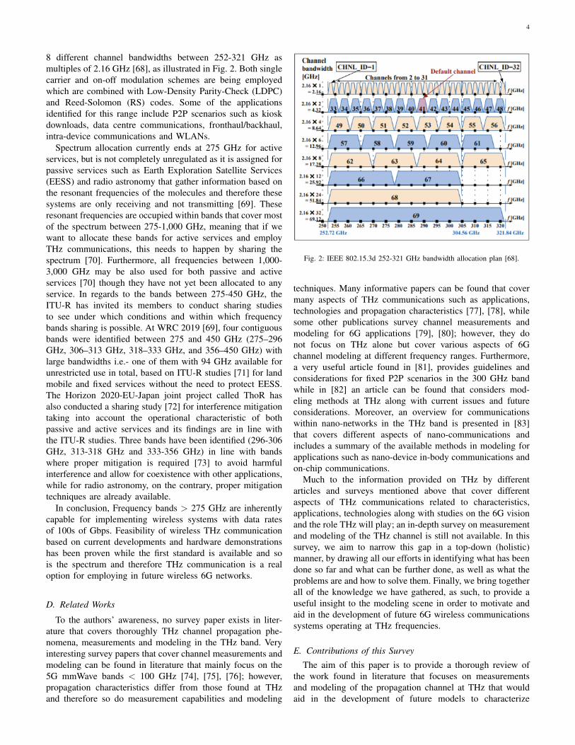
8 different channel bandwidths between 252-321 GHz asmultiples of 2.16 GHz [68], as illustrated in Fig. 2. Both singlecarrier and on-off modulation schemes are being employedwhich are combined with Low-Density Parity-Check (LDPC)and Reed-Solomon (RS) codes. Some of the applicationsidentified for this range include P2P scenarios such as kioskdownloads, data centre communications, fronthaul/backhaul,intra-device communications and WLANs.
Spectrum allocation currently ends at 275 GHz for activeservices, but is not completely unregulated as it is assigned forpassive services such as Earth Exploration Satellite Services(EESS) and radio astronomy that gather information based onthe resonant frequencies of the molecules and therefore thesesystems are only receiving and not transmitting [69]. Theseresonant frequencies are occupied within bands that cover mostof the spectrum between 275-1,000 GHz, meaning that if wewant to allocate these bands for active services and employTHz communications, this needs to happen by sharing thespectrum [70]. Furthermore, all frequencies between 1,000-3,000 GHz may be also used for both passive and activeservices [70] though they have not yet been allocated to anyservice. In regards to the bands between 275-450 GHz, theITU-R has invited its members to conduct sharing studiesto see under which conditions and within which frequencybands sharing is possible. At WRC 2019 [69], four contiguousbands were identified between 275 and 450 GHz (275–296GHz, 306–313 GHz, 318–333 GHz, and 356–450 GHz) withlarge bandwidths i.e.- one of them with 94 GHz available forunrestricted use in total, based on ITU-R studies [71] for landmobile and fixed services without the need to protect EESS.The Horizon 2020-EU-Japan joint project called ThoR hasalso conducted a sharing study [72] for interference mitigationtaking into account the operational characteristic of bothpassive and active services and its findings are in line withthe ITU-R studies. Three bands have been identified (296-306GHz, 313-318 GHz and 333-356 GHz) in line with bandswhere proper mitigation is required [73] to avoid harmfulinterference and allow for coexistence with other applications,while for radio astronomy, on the contrary, proper mitigationtechniques are already available.
In conclusion, Frequency bands > 275 GHz are inherentlycapable for implementing wireless systems with data ratesof 100s of Gbps. Feasibility of wireless THz communicationbased on current developments and hardware demonstrationshas been proven while the first standard is available and sois the spectrum and therefore THz communication is a realoption for employing in future wireless 6G networks.
D. Related Works
To the authors’ awareness, no survey paper exists in liter-ature that covers thoroughly THz channel propagation phe-nomena, measurements and modeling in the THz band. Veryinteresting survey papers that cover channel measurements andmodeling can be found in literature that mainly focus on the5G mmWave bands < 100 GHz [74], [75], [76]; however,propagation characteristics differ from those found at THzand therefore so do measurement capabilities and modeling
Fig. 2: IEEE 802.15.3d 252-321 GHz bandwidth allocation plan [68].
techniques. Many informative papers can be found that covermany aspects of THz communications such as applications,technologies and propagation characteristics [77], [78], whilesome other publications survey channel measurements andmodeling for 6G applications [79], [80]; however, they donot focus on THz alone but cover various aspects of 6Gchannel modeling at different frequency ranges. Furthermore,a very useful article found in [81], provides guidelines andconsiderations for fixed P2P scenarios in the 300 GHz bandwhile in [82] an article can be found that considers mod-eling methods at THz along with current issues and futureconsiderations. Moreover, an overview for communicationswithin nano-networks in the THz band is presented in [83]that covers different aspects of nano-communications andincludes a summary of the available methods in modeling forapplications such as nano-device in-body communications andon-chip communications.
Much to the information provided on THz by differentarticles and surveys mentioned above that cover differentaspects of THz communications related to characteristics,applications, technologies along with studies on the 6G visionand the role THz will play; an in-depth survey on measurementand modeling of the THz channel is still not available. In thissurvey, we aim to narrow this gap in a top-down (holistic)manner, by drawing all our efforts in identifying what has beendone so far and what can be further done, as well as what theproblems are and how to solve them. Finally, we bring togetherall of the knowledge we have gathered, as such, to provide auseful insight to the modeling scene in order to motivate andaid in the development of future 6G wireless communicationssystems operating at THz frequencies.
E. Contributions of this Survey
The aim of this paper is to provide a thorough review ofthe work found in literature that focuses on measurementsand modeling of the propagation channel at THz that wouldaid in the development of future models to characterize
5
the propagation environment for the deployment of futurecommunications systems. Initially, we describe the differentpropagation characteristics in terms of specific attenuationdue to path loss and precipitation as well as attenuationresulting from various interactions with different materials.We then describe the use cases at THz and identify what thesystem requirements for conducting measurements are. Next,we describe the methods that can be employed for channelsounding at THz as well as channel modeling techniquesthat can be applied to characterize wave propagation at THz.Furthermore, we survey important works found in literature re-lated to channel characterization for potential 6G applications.Onward, we present open challenges along with solutions formodeling at THz frequencies higher than 300 GHz (λ < 1mm), where the current spectrum allocation ends and modelingefforts are still in their early stages. The contributions of thissurvey are summarized as follows:
• We begin by presenting the different THz propagationphenomena experienced in free space at THz and theirassociated models and describe the unique interactionsexperienced by the THz waves in the surrounding envi-ronment at this frequency band.
• Secondly, we define and give a short description of theuse cases identified and set the system requirements forconducting measurements at THz based on these usecases. Then, we describe the channel sounding optionsavailable that are required for performing measurementsat THz, discuss their advantages and disadvantages anddiscuss how they address the measurement requirementsidentified.
• Next, we explore the physical and analytical modelingapproaches that could be employed at THz to describethe channel behaviour and discuss which methods aremost popular for extracting the propagation channel’scharacteristics.
• We survey scenario oriented as well as general channelmeasurement campaigns and modeling efforts found inliterature at THz for static P2P and dynamic scenariosthat include mobility.
• Finally, we present challenges in measurement and mod-eling at frequencies > 300 GHz and discuss possiblesolutions and research directions that can contribute tothe future modeling scene.
F. Outline
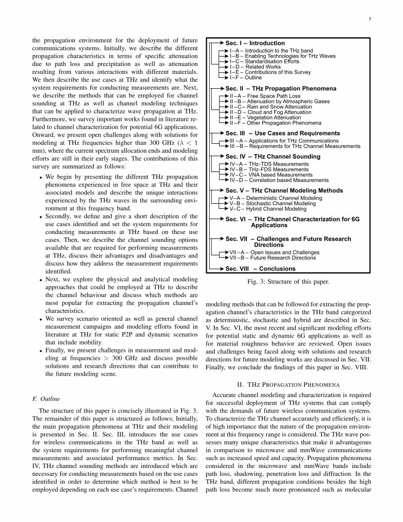
The structure of this paper is concisely illustrated in Fig. 3.The remainder of this paper is structured as follows; Initially,the main propagation phenomena at THz and their modelingis presented in Sec. II. Sec. III, introduces the use casesfor wireless communications in the THz band as well asthe system requirements for performing meaningful channelmeasurements and associated performance metrics. In Sec.IV, THz channel sounding methods are introduced which arenecessary for conducting measurements based on the use casesidentified in order to determine which method is best to beemployed depending on each use case’s requirements. Channel
Sec. I – Introduction
I–A – Introduction to the THz band I–B – Enabling Technologies for THz WavesI–C – Standardisation EffortsI–D – Related WorksI–E – Contributions of this SurveyI–F – Outline
Sec. II – THz Propagation Phenomena
II –A – Free Space Path LossII –B – Attenuation by Atmospheric GasesII –C – Rain and Snow AttenuationII –D – Cloud and Fog AttenuationII –E – Vegetation AttenuationII –F – Other Propagation Phenomena
Sec. III – Use Cases and Requirements
III –A – Applications for THz CommunicationsIII –B – Requirements for THz Channel Measurements
Sec. IV – THz Channel Sounding
IV–A – THz-TDS MeasurementsIV–B – THz-FDS MeasurementsIV–C – VNA based MeasurementsIV–D – Correlation based Measurements
Sec. V – THz Channel Modeling Methods
V–A – Deterministic Channel ModelingV–B – Stochastic Channel ModelingV–C – Hybrid Channel Modeling
Sec. VI – THz Channel Characterization for 6G Applications
Sec. VII – Challenges and Future Research Directions
VII –A – Open Issues and ChallengesVII –B – Future Research Directions
Sec. VIII – Conclusions
Fig. 3: Structure of this paper.
modeling methods that can be followed for extracting the prop-agation channel’s characteristics in the THz band categorizedas deterministic, stochastic and hybrid are described in Sec.V. In Sec. VI, the most recent and significant modeling effortsfor potential static and dynamic 6G applications as well asfor material roughness behavior are reviewed. Open issuesand challenges being faced along with solutions and researchdirections for future modeling works are discussed in Sec. VII.Finally, we conclude the findings of this paper in Sec. VIII.
II. THZ PROPAGATION PHENOMENA
Accurate channel modeling and characterization is requiredfor successful deployment of THz systems that can complywith the demands of future wireless communication systems.To characterize the THz channel accurately and efficiently, it isof high importance that the nature of the propagation environ-ment at this frequency range is considered. The THz wave pos-sesses many unique characteristics that make it advantageousin comparison to microwave and mmWave communicationssuch as increased speed and capacity. Propagation phenomenaconsidered in the microwave and mmWave bands includepath loss, shadowing, penetration loss and diffraction. In theTHz band, different propagation conditions besides the highpath loss become much more pronounced such as molecular
6
0 500 1000 1500 2000 2500 3000
Frequency (GHz)
100
120
140
160
180
200
Path
Loss (
dB
)
Range: 100 m
Range: 1 km
Range: 10 km
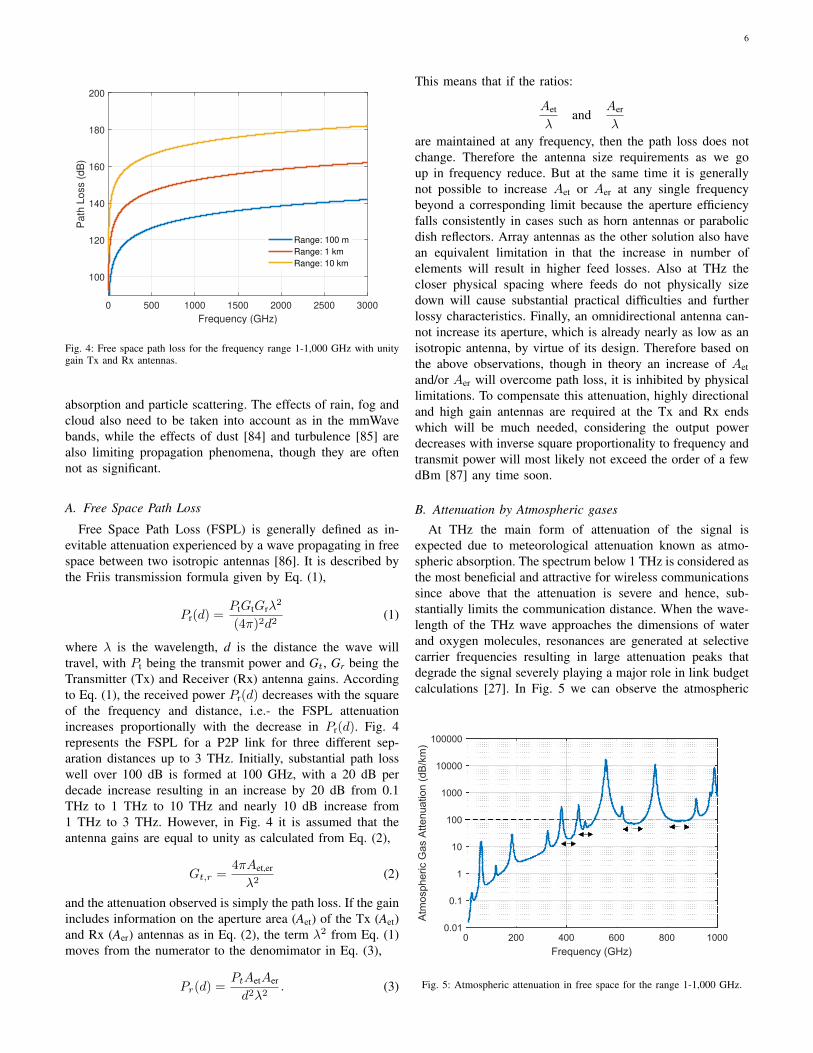
Fig. 4: Free space path loss for the frequency range 1-1,000 GHz with unitygain Tx and Rx antennas.
absorption and particle scattering. The effects of rain, fog andcloud also need to be taken into account as in the mmWavebands, while the effects of dust [84] and turbulence [85] arealso limiting propagation phenomena, though they are oftennot as significant.
A. Free Space Path Loss
Free Space Path Loss (FSPL) is generally defined as in-evitable attenuation experienced by a wave propagating in freespace between two isotropic antennas [86]. It is described bythe Friis transmission formula given by Eq. (1),
Pr(d) =PtGtGrλ
2
(4π)2d2(1)
where λ is the wavelength, d is the distance the wave willtravel, with Pt being the transmit power and Gt, Gr being theTransmitter (Tx) and Receiver (Rx) antenna gains. Accordingto Eq. (1), the received power Pr(d) decreases with the squareof the frequency and distance, i.e.- the FSPL attenuationincreases proportionally with the decrease in Pr(d). Fig. 4represents the FSPL for a P2P link for three different sep-aration distances up to 3 THz. Initially, substantial path losswell over 100 dB is formed at 100 GHz, with a 20 dB perdecade increase resulting in an increase by 20 dB from 0.1THz to 1 THz to 10 THz and nearly 10 dB increase from1 THz to 3 THz. However, in Fig. 4 it is assumed that theantenna gains are equal to unity as calculated from Eq. (2),
Gt,r =4πAet,er
λ2(2)
and the attenuation observed is simply the path loss. If the gainincludes information on the aperture area (Aet) of the Tx (Aet)and Rx (Aer) antennas as in Eq. (2), the term λ2 from Eq. (1)moves from the numerator to the denomimator in Eq. (3),
Pr(d) =PtAetAer
d2λ2. (3)
This means that if the ratios:
Aet
λand
Aer
λ
are maintained at any frequency, then the path loss does notchange. Therefore the antenna size requirements as we goup in frequency reduce. But at the same time it is generallynot possible to increase Aet or Aer at any single frequencybeyond a corresponding limit because the aperture efficiencyfalls consistently in cases such as horn antennas or parabolicdish reflectors. Array antennas as the other solution also havean equivalent limitation in that the increase in number ofelements will result in higher feed losses. Also at THz thecloser physical spacing where feeds do not physically sizedown will cause substantial practical difficulties and furtherlossy characteristics. Finally, an omnidirectional antenna can-not increase its aperture, which is already nearly as low as anisotropic antenna, by virtue of its design. Therefore based onthe above observations, though in theory an increase of Aetand/or Aer will overcome path loss, it is inhibited by physicallimitations. To compensate this attenuation, highly directionaland high gain antennas are required at the Tx and Rx endswhich will be much needed, considering the output powerdecreases with inverse square proportionality to frequency andtransmit power will most likely not exceed the order of a fewdBm [87] any time soon.
B. Attenuation by Atmospheric gases
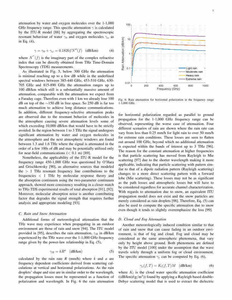
At THz the main form of attenuation of the signal isexpected due to meteorological attenuation known as atmo-spheric absorption. The spectrum below 1 THz is considered asthe most beneficial and attractive for wireless communicationssince above that the attenuation is severe and hence, sub-stantially limits the communication distance. When the wave-length of the THz wave approaches the dimensions of waterand oxygen molecules, resonances are generated at selectivecarrier frequencies resulting in large attenuation peaks thatdegrade the signal severely playing a major role in link budgetcalculations [27]. In Fig. 5 we can observe the atmospheric
0 200 400 600 800 1000
Frequency (GHz)
0.01
0.1
1
10
100
1000
10000
100000
Atm
osp
he
ric G
as A
tte
nu
atio
n (
dB
/km
)
Fig. 5: Atmospheric attenuation in free space for the range 1-1,000 GHz.
7
attenuation by water and oxygen molecules over the 1-1,000GHz frequency range. This specific attenuation γ is calculatedby the ITU-R model [88] by aggregating the spectroscopicresonant behaviour of water γ0 and oxygen molecules γω asin Eq. (4),
γ = γ0 + γω = 0.1820fN ′′(f) (dB/km) (4)
where N′′(f) is the imaginary part of the complex refractive
index that can be directly obtained from THz Time-DomainSpectroscopy (TDS) measurements.
As illustrated in Fig. 5, below 300 GHz the attenuationis minimal reaching up to a few dB while in the underlinedspectral windows between 385-440 GHz, 453-510 GHz, 630-705 GHz and 815-890 GHz the attenuation ranges up to100 dB/km which still is a substantially massive amount ofattenuation, comparable with the attenuation we expect froma Faraday cage. Therefore even with 1 km we already lose 100dB on top of the ∼150 dB in free space. So 250 dB is far toomuch attenuation to achieve long distance communications.In addition, different frequency-selective attenuation peaksare observed due to the resonant behavior of molecules inthe atmosphere causing severe attenuation levels some ofwhich exceeding 10,000 dB/km that would have to be strictlyavoided. In the region between 1 to 3 THz the signal undergoessignificant attenuation by water and oxygen molecules inthe atmosphere and the next atmospheric windows are foundbetween 1.3 and 1.6 THz where the signal is attenuated in theorder of a few 100s of dB and may be potentially utilized onlyfor near-field communications (< 0.1 m) [89].
Nonetheless, the applicability of the ITU-R model for thefrequency range 450-1,000 GHz was questioned by O’Haraand Grischkowsky [90], as alternative sources that modeledthe > 1 THz resonant frequency line contributions to thefrequencies < 1 THz by molecular response theory andthe absorption continuum using the two-parameter continuumapproach, showed more consistency resulting in a closer matchto THz-TDS experimental results of total absorption [91], [92].Moreover, molecular absorption noise is another contributingfactor that degrades the signal strength that requires furtheranalysis and appropriate modeling [93].
C. Rain and Snow Attenuation
Additional forms of meteorological attenuation that theTHz wave may experience when propagating in an outdoorenvironment are those of rain and snow [94]. The ITU modelprovided in [95], describes the rain attenuation, γR in dB/kmexperienced by the THz wave over the 1-1,000 GHz frequencyrange given by the power-law relationship in Eq. (5),
γR = kRa (dB/km) (5)
calculated by the rain rate R (mm/h) where k and a arefrequency dependent coefficients derived from scattering cal-culations at vertical and horizontal polarizations. As the raindroplets’ shape and size are in similar order to the wavelength,the propagation losses must be represented as a function ofpolarization and wavelength. In Fig. 6 the rain attenuation
0 200 400 600 800 1000
Frequency (GHz)
0.01
0.1
1
10
100
Ra
in A
tte
nu
atio
n (
dB
/km
)
Light rain
Moderate rain
Heavy rain
Extreme rain
Fig. 6: Rain attenuation for horizontal polarization in the frequency range1-1,000 GHz.
for horizontal polarization regarded as parallel to groundpropagation for the 1-1,000 GHz frequency range can beobserved, representing the worse case of attenuation. Fourdifferent scenarios of rain are shown where the rain rate canvary from less than 0.25 mm/h for light rain to over 50 mm/hfor extreme rain conditions. These losses are seen to flattenout around 100 GHz, beyond which no additional attenuationis expected within the bands of interest up to 3 THz [96].The reason for the constant attenuation at higher frequenciesis that particle scattering has moved from Rayleigh to Miescattering [97] due to the shorter wavelength making it moreapplicable, indicating that particle scattering with pattern sim-ilar to that of a dipole radiation pattern (Rayleigh scattering)changes to a more direct scattering pattern with a forwardlobe (Mie scattering). These losses may not be as significantas the path losses and atmospheric losses but will have tobe considered regardless for accurate channel characterization.With regards to attenuation due to snow, an equivalent ITUpropagation model does not exist and the snow particles aremerely considered as rain droplets [98]. Therefore, Eq. (5) canalso be used to compute the specific attenuation due to snoweven though it tends to slightly overemphasize the loss [99].
D. Cloud and Fog Attenuation
Another meteorologically induced condition similar to thatof rain and snow that can cause fading in an outdoor envi-ronment, is that of fog and cloud. Fog and cloud may beconsidered as the same atmospheric phenomena, that varyonly by height above ground. Both phenomena are definedby the ITU model [100] under the assumption that the wavetravels solely through a uniform fog or cloud environment.The specific attenuation γc can be computed by Eq. (6),
γc(f, T ) = Kl(f, T )M (dB/km) (6)
where Kl is the cloud water specific attenuation coefficient((dB/km)/(g/m3)) found by applying a Rayleigh based double-Debye scattering model that is used to extract the dielectric
8
0 200 400 600 800 1000
Frequency (GHz)
0.001
0.01
0.1
1
10
100
Fo
g o
r C
lou
d A
tte
nu
atio
n (
dB
/km
)
Medium fog/cloud
Heavy fog/cloud
Fig. 7: Fog or cloud specific attenuation for the range 1-1,000 GHz.
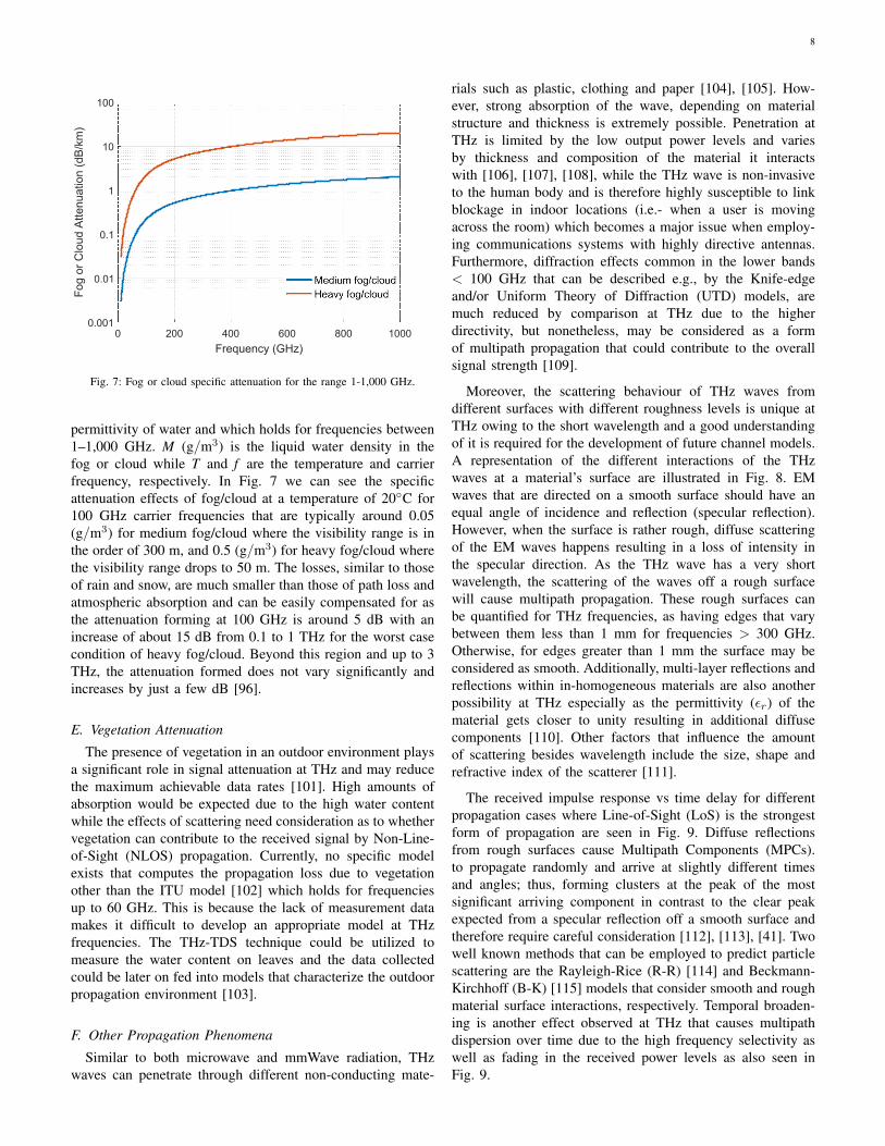
permittivity of water and which holds for frequencies between1–1,000 GHz. M (g/m3) is the liquid water density in thefog or cloud while T and f are the temperature and carrierfrequency, respectively. In Fig. 7 we can see the specificattenuation effects of fog/cloud at a temperature of 20◦C for100 GHz carrier frequencies that are typically around 0.05(g/m3) for medium fog/cloud where the visibility range is inthe order of 300 m, and 0.5 (g/m3) for heavy fog/cloud wherethe visibility range drops to 50 m. The losses, similar to thoseof rain and snow, are much smaller than those of path loss andatmospheric absorption and can be easily compensated for asthe attenuation forming at 100 GHz is around 5 dB with anincrease of about 15 dB from 0.1 to 1 THz for the worst casecondition of heavy fog/cloud. Beyond this region and up to 3THz, the attenuation formed does not vary significantly andincreases by just a few dB [96].
E. Vegetation Attenuation
The presence of vegetation in an outdoor environment playsa significant role in signal attenuation at THz and may reducethe maximum achievable data rates [101]. High amounts ofabsorption would be expected due to the high water contentwhile the effects of scattering need consideration as to whethervegetation can contribute to the received signal by Non-Line-of-Sight (NLOS) propagation. Currently, no specific modelexists that computes the propagation loss due to vegetationother than the ITU model [102] which holds for frequenciesup to 60 GHz. This is because the lack of measurement datamakes it difficult to develop an appropriate model at THzfrequencies. The THz-TDS technique could be utilized tomeasure the water content on leaves and the data collectedcould be later on fed into models that characterize the outdoorpropagation environment [103].
F. Other Propagation Phenomena
Similar to both microwave and mmWave radiation, THzwaves can penetrate through different non-conducting mate-
rials such as plastic, clothing and paper [104], [105]. How-ever, strong absorption of the wave, depending on materialstructure and thickness is extremely possible. Penetration atTHz is limited by the low output power levels and variesby thickness and composition of the material it interactswith [106], [107], [108], while the THz wave is non-invasiveto the human body and is therefore highly susceptible to linkblockage in indoor locations (i.e.- when a user is movingacross the room) which becomes a major issue when employ-ing communications systems with highly directive antennas.Furthermore, diffraction effects common in the lower bands< 100 GHz that can be described e.g., by the Knife-edgeand/or Uniform Theory of Diffraction (UTD) models, aremuch reduced by comparison at THz due to the higherdirectivity, but nonetheless, may be considered as a formof multipath propagation that could contribute to the overallsignal strength [109].
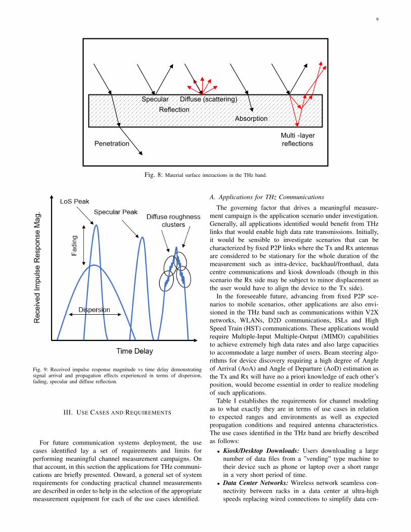
Moreover, the scattering behaviour of THz waves fromdifferent surfaces with different roughness levels is unique atTHz owing to the short wavelength and a good understandingof it is required for the development of future channel models.A representation of the different interactions of the THzwaves at a material’s surface are illustrated in Fig. 8. EMwaves that are directed on a smooth surface should have anequal angle of incidence and reflection (specular reflection).However, when the surface is rather rough, diffuse scatteringof the EM waves happens resulting in a loss of intensity inthe specular direction. As the THz wave has a very shortwavelength, the scattering of the waves off a rough surfacewill cause multipath propagation. These rough surfaces canbe quantified for THz frequencies, as having edges that varybetween them less than 1 mm for frequencies > 300 GHz.Otherwise, for edges greater than 1 mm the surface may beconsidered as smooth. Additionally, multi-layer reflections andreflections within in-homogeneous materials are also anotherpossibility at THz especially as the permittivity (ϵr) of thematerial gets closer to unity resulting in additional diffusecomponents [110]. Other factors that influence the amountof scattering besides wavelength include the size, shape andrefractive index of the scatterer [111].
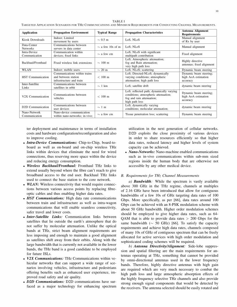
The received impulse response vs time delay for differentpropagation cases where Line-of-Sight (LoS) is the strongestform of propagation are seen in Fig. 9. Diffuse reflectionsfrom rough surfaces cause Multipath Components (MPCs).to propagate randomly and arrive at slightly different timesand angles; thus, forming clusters at the peak of the mostsignificant arriving component in contrast to the clear peakexpected from a specular reflection off a smooth surface andtherefore require careful consideration [112], [113], [41]. Twowell known methods that can be employed to predict particlescattering are the Rayleigh-Rice (R-R) [114] and Beckmann-Kirchhoff (B-K) [115] models that consider smooth and roughmaterial surface interactions, respectively. Temporal broaden-ing is another effect observed at THz that causes multipathdispersion over time due to the high frequency selectivity aswell as fading in the received power levels as also seen inFig. 9.
9
Penetration
Reflection
Specular Diffuse (scattering)
Absorption
Multi -layer
reflections
Fig. 8: Material surface interactions in the THz band.
Fig. 9: Received impulse response magnitude vs time delay demonstratingsignal arrival and propagation effects experienced in terms of dispersion,fading, specular and diffuse reflection.
III. USE CASES AND REQUIREMENTS
For future communication systems deployment, the usecases identified lay a set of requirements and limits forperforming meaningful channel measurement campaigns. Onthat account, in this section the applications for THz communi-cations are briefly presented. Onward, a general set of systemrequirements for conducting practical channel measurementsare described in order to help in the selection of the appropriatemeasurement equipment for each of the use cases identified.
A. Applications for THz Communications
The governing factor that drives a meaningful measure-ment campaign is the application scenario under investigation.Generally, all applications identified would benefit from THzlinks that would enable high data rate transmissions. Initially,it would be sensible to investigate scenarios that can becharacterized by fixed P2P links where the Tx and Rx antennasare considered to be stationary for the whole duration of themeasurement such as intra-device, backhaul/fronthaul, datacentre communications and kiosk downloads (though in thisscenario the Rx side may be subject to minor displacement asthe user would have to align the device to the Tx side).
In the foreseeable future, advancing from fixed P2P sce-narios to mobile scenarios, other applications are also envi-sioned in the THz band such as communications within V2Xnetworks, WLANs, D2D communications, ISLs and HighSpeed Train (HST) communications. These applications wouldrequire Multiple-Input Multiple-Output (MIMO) capabilitiesto achieve extremely high data rates and also large capacitiesto accommodate a large number of users. Beam steering algo-rithms for device discovery requiring a high degree of Angleof Arrival (AoA) and Angle of Departure (AoD) estimation asthe Tx and Rx will have no a priori knowledge of each other’sposition, would become essential in order to realize modelingof such applications.
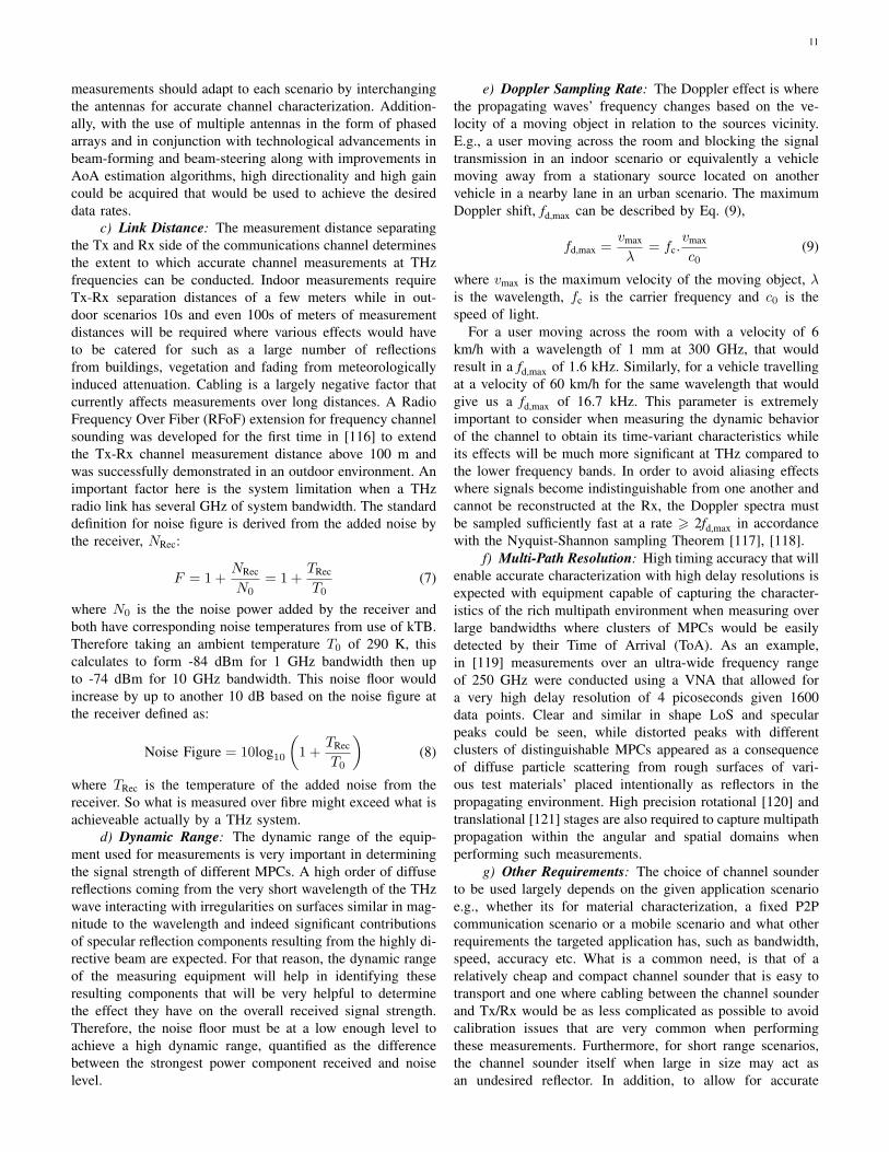
Table I establishes the requirements for channel modelingas to what exactly they are in terms of use cases in relationto expected ranges and environments as well as expectedpropagation conditions and required antenna characteristics.The use cases identified in the THz band are briefly describedas follows:
• Kiosk/Desktop Downloads: Users downloading a largenumber of data files from a ”vending” type machine totheir device such as phone or laptop over a short rangein a very short period of time.
• Data Center Networks: Wireless network seamless con-nectivity between racks in a data center at ultra-highspeeds replacing wired connections to simplify data cen-
10
TABLE ITARGETED APPLICATION SCENARIOS FOR THZ COMMUNICATIONS AND MINIMUM REQUIREMENTS FOR CONDUCTING CHANNEL MEASUREMENTS.
Application Propagation Environment Typical Range Propagation Characteristics Antenna AlignmentRequirements
Kiosk Downloads Indoor; Limitedmovement by users ∼ 0.5 m LoS, NLoS Manual alignment
of Rx by userData-CenterNetworks
Communications betweenservers in data center ∼ a few 10s of m LoS; NLoS Manual alignment
Intra-DeviceCommunication
Communication withindevices; fixed links ∼ a few cm LoS; NLoS with significant
multipath contribution Fixed alignment
Backhaul/Fronthaul Fixed wireless link extensions ∼ 100 mLoS; Atmospheric attenuation;fog and Rain attenuation;very high path loss
Highly directiveantennas; fixed alignment
WLAN Indoor; mobile users ∼ 20 m LoS; NLoS; scattering Dynamic beam steering
HST CommunicationCommunications within trainsand between stationinfrastructure and train
< 100 mLoS; Directed-NLoS; dynamicallyvarying conditions; atmosphericattenuation; high path loss
Dynamic beam steering;high AoA estimationaccuracy
Inter-SatelliteLinks
Communications betweensatellites in orbit ∼ 1 km LoS; satellite drift dynamic beam steering
V2X Communication Communications betweenvehicles < 100 m
LoS; reflected path; dynamically varyingconditions; atmospheric attenuation;fog and rain attenuation;high path loss
Dynamic beam steering;high AoA estimationaccuracy
D2D Communication Communications betweenuser devices ∼ 1 m LoS; dynamically varying
conditions; molecular attenuation; dynamic beam steering
Nano-NetworkCommunication
Nano-device communicationwithin nano-networks; in-vivo; ∼ a few cm Tissue penetration loss; scattering Dynamic beam steering
ter deployment and maintenance in terms of installationcosts and hardware configuration/reconfiguration and alsoto improve cooling.
• Intra-Device Communications: Chip-to-Chip, board-to-board as well as on-board and on-chip wireless THzlinks within devices that eliminate the need for wiredconnections, thus reserving more space within the deviceand reducing energy consumption.
• Wireless Backhaul/Fronthaul: Fronthaul THz links toextend usually beyond where the fibre can’t reach to givebroadband access to the end user. Backhaul THz linksused to connect the base station to the core network.
• WLAN: Wireless connectivity that would require connec-tions between various access points by replacing fibre-optic cables and thus enabling higher data rates.
• HST Communications: High data rate communicationsbetween train and infrastructure as well as intra-wagoncommunications that will enable seamless connectivity,safer travel and lower costs.
• Inter-Satellite Links: Communication links betweensatellites that lie outside the earth’s atmosphere that donot suffer by molecular attenuation. Unlike the opticalbands at THz, strict beam alignment requirements areless imposing and enough to maintain a good alignmentas satellites shift away from their orbits. Along with thelarge bandwidth that is currently not available in the lowerbands, the THz band is a good candidate to be employedfor future ISLs.
• V2X Communications: THz Communications within ve-hicular networks that can support a wide range of sce-narios involving vehicles, infrastructure and pedestriansoffering benefits such as enhanced user experience, im-proved road safety and air quality.
• D2D Communications: D2D communications have sur-faced as a major technology for enhancing spectrum
utilization in the next generation of cellular networks.D2D exploits the close proximity of various devicesin order to share resources efficiently so that higherdata rates, reduced latency and higher levels of systemcapacity can be achieved.
• Nano-Networks: Nano-machine enabled communicationssuch as in-vivo communications within sub-mm sizedregions inside the human body that are otherwise notaccessible by any other medical device.
B. Requirements for THz Channel Measurements
a) Bandwidth: While the spectrum is vastly availableabove 300 GHz in the THz regime, channels at multiplesof 2.16 GHz have been introduced that allow for contiguousbandwidths of a few 10s of GHz targeting data rates of 100Gbps. More specifically, as per [66], data rates around 100Gbps can be achieved with an 8-PSK modulation scheme withabout 50 GHz bandwidth. Higher order modulation schemesshould be employed to give higher data rates, such as 64-QAM that is able to provide data rates > 200 Gbps for thesame bandwidth (∼ 50 GHz) [66]. To satisfy the capacityrequirements and achieve high data rates, channels composedof many 10s of GHz of contiguous spectrum that can be freelyallocated for active services with high order modulation andsophisticated coding schemes will be required.
b) Antenna Directivity/Alignment: Side-lobe suppres-sion and spatial filtering are the main requirements for an-tennas operating at THz, something that cannot be providedby omni-directional antennas used in the lower frequencybands. Therefore, highly directive antennas with high gainare required which are very much necessary to combat thehigh path loss and large atmospheric absorption effects ofthe highly frequency selective THz channels and also providestrong enough signal components that would be detected bythe receivers. The antenna selected should be easily rotated and
11
measurements should adapt to each scenario by interchangingthe antennas for accurate channel characterization. Addition-ally, with the use of multiple antennas in the form of phasedarrays and in conjunction with technological advancements inbeam-forming and beam-steering along with improvements inAoA estimation algorithms, high directionality and high gaincould be acquired that would be used to achieve the desireddata rates.
c) Link Distance: The measurement distance separatingthe Tx and Rx side of the communications channel determinesthe extent to which accurate channel measurements at THzfrequencies can be conducted. Indoor measurements requireTx-Rx separation distances of a few meters while in out-door scenarios 10s and even 100s of meters of measurementdistances will be required where various effects would haveto be catered for such as a large number of reflectionsfrom buildings, vegetation and fading from meteorologicallyinduced attenuation. Cabling is a largely negative factor thatcurrently affects measurements over long distances. A RadioFrequency Over Fiber (RFoF) extension for frequency channelsounding was developed for the first time in [116] to extendthe Tx-Rx channel measurement distance above 100 m andwas successfully demonstrated in an outdoor environment. Animportant factor here is the system limitation when a THzradio link has several GHz of system bandwidth. The standarddefinition for noise figure is derived from the added noise bythe receiver, NRec:
F = 1 +NRec
N0= 1 +
TRec
T0(7)
where N0 is the the noise power added by the receiver andboth have corresponding noise temperatures from use of kTB.Therefore taking an ambient temperature T0 of 290 K, thiscalculates to form -84 dBm for 1 GHz bandwidth then upto -74 dBm for 10 GHz bandwidth. This noise floor wouldincrease by up to another 10 dB based on the noise figure atthe receiver defined as:
Noise Figure = 10log10
(1 +
TRec
T0
)(8)
where TRec is the temperature of the added noise from thereceiver. So what is measured over fibre might exceed what isachieveable actually by a THz system.
d) Dynamic Range: The dynamic range of the equip-ment used for measurements is very important in determiningthe signal strength of different MPCs. A high order of diffusereflections coming from the very short wavelength of the THzwave interacting with irregularities on surfaces similar in mag-nitude to the wavelength and indeed significant contributionsof specular reflection components resulting from the highly di-rective beam are expected. For that reason, the dynamic rangeof the measuring equipment will help in identifying theseresulting components that will be very helpful to determinethe effect they have on the overall received signal strength.Therefore, the noise floor must be at a low enough level toachieve a high dynamic range, quantified as the differencebetween the strongest power component received and noiselevel.
e) Doppler Sampling Rate: The Doppler effect is wherethe propagating waves’ frequency changes based on the ve-locity of a moving object in relation to the sources vicinity.E.g., a user moving across the room and blocking the signaltransmission in an indoor scenario or equivalently a vehiclemoving away from a stationary source located on anothervehicle in a nearby lane in an urban scenario. The maximumDoppler shift, fd,max can be described by Eq. (9),
fd,max =vmax
λ= fc.
vmax
c0(9)
where vmax is the maximum velocity of the moving object, λis the wavelength, fc is the carrier frequency and c0 is thespeed of light.
For a user moving across the room with a velocity of 6km/h with a wavelength of 1 mm at 300 GHz, that wouldresult in a fd,max of 1.6 kHz. Similarly, for a vehicle travellingat a velocity of 60 km/h for the same wavelength that wouldgive us a fd,max of 16.7 kHz. This parameter is extremelyimportant to consider when measuring the dynamic behaviorof the channel to obtain its time-variant characteristics whileits effects will be much more significant at THz compared tothe lower frequency bands. In order to avoid aliasing effectswhere signals become indistinguishable from one another andcannot be reconstructed at the Rx, the Doppler spectra mustbe sampled sufficiently fast at a rate ⩾ 2fd,max in accordancewith the Nyquist-Shannon sampling Theorem [117], [118].
f) Multi-Path Resolution: High timing accuracy that willenable accurate characterization with high delay resolutions isexpected with equipment capable of capturing the character-istics of the rich multipath environment when measuring overlarge bandwidths where clusters of MPCs would be easilydetected by their Time of Arrival (ToA). As an example,in [119] measurements over an ultra-wide frequency rangeof 250 GHz were conducted using a VNA that allowed fora very high delay resolution of 4 picoseconds given 1600data points. Clear and similar in shape LoS and specularpeaks could be seen, while distorted peaks with differentclusters of distinguishable MPCs appeared as a consequenceof diffuse particle scattering from rough surfaces of vari-ous test materials’ placed intentionally as reflectors in thepropagating environment. High precision rotational [120] andtranslational [121] stages are also required to capture multipathpropagation within the angular and spatial domains whenperforming such measurements.
g) Other Requirements: The choice of channel sounderto be used largely depends on the given application scenarioe.g., whether its for material characterization, a fixed P2Pcommunication scenario or a mobile scenario and what otherrequirements the targeted application has, such as bandwidth,speed, accuracy etc. What is a common need, is that of arelatively cheap and compact channel sounder that is easy totransport and one where cabling between the channel sounderand Tx/Rx would be as less complicated as possible to avoidcalibration issues that are very common when performingthese measurements. Furthermore, for short range scenarios,the channel sounder itself when large in size may act asan undesired reflector. In addition, to allow for accurate
12
(a) (b)
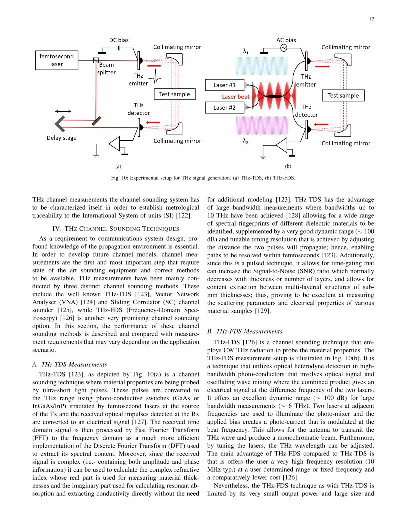
Fig. 10: Experimental setup for THz signal generation. (a) THz-TDS, (b) THz-FDS.
THz channel measurements the channel sounding system hasto be characterized itself in order to establish metrologicaltraceability to the International System of units (SI) [122].
IV. THZ CHANNEL SOUNDING TECHNIQUES
As a requirement to communications system design, pro-found knowledge of the propagation environment is essential.In order to develop future channel models, channel mea-surements are the first and most important step that requirestate of the art sounding equipment and correct methodsto be available. THz measurements have been mainly con-ducted by three distinct channel sounding methods. Theseinclude the well known THz-TDS [123], Vector NetworkAnalyser (VNA) [124] and Sliding Correlator (SC) channelsounder [125], while THz-FDS (Frequency-Domain Spec-troscopy) [126] is another very promising channel soundingoption. In this section, the performance of these channelsounding methods is described and compared with measure-ment requirements that may vary depending on the applicationscenario.
A. THz-TDS MeasurementsTHz-TDS [123], as depicted by Fig. 10(a) is a channel
sounding technique where material properties are being probedby ultra-short light pulses. These pulses are converted tothe THz range using photo-conductive switches (GaAs orInGaAs/InP) irradiated by femtosecond lasers at the sourceof the Tx and the received optical impulses detected at the Rxare converted to an electrical signal [127]. The received timedomain signal is then processed by Fast Fourier Transform(FFT) to the frequency domain as a much more efficientimplementation of the Discrete Fourier Transform (DFT) usedto extract its spectral content. Moreover, since the receivedsignal is complex (i.e.- containing both amplitude and phaseinformation) it can be used to calculate the complex refractiveindex whose real part is used for measuring material thick-nesses and the imaginary part used for calculating resonant ab-sorption and extracting conductivity directly without the need
for additional modeling [123]. THz-TDS has the advantageof large bandwidth measurements where bandwidths up to10 THz have been achieved [128] allowing for a wide rangeof spectral fingerprints of different dielectric materials to beidentified, supplemented by a very good dynamic range (∼ 100dB) and tunable timing resolution that is achieved by adjustingthe distance the two pulses will propagate; hence, enablingpaths to be resolved within femtoseconds [123]. Additionally,since this is a pulsed technique, it allows for time-gating thatcan increase the Signal-to-Noise (SNR) ratio which normallydecreases with thickness or number of layers, and allows forcontent extraction between multi-layered structures of sub-mm thicknesses; thus, proving to be excellent at measuringthe scattering parameters and electrical properties of variousmaterial samples [129].
B. THz-FDS Measurements
THz-FDS [126] is a channel sounding technique that em-ploys CW THz radiation to probe the material properties. TheTHz-FDS measurement setup is illustrated in Fig. 10(b). It isa technique that utilizes optical heterodyne detection in high-bandwidth photo-conductors that involves optical signal andoscillating wave mixing where the combined product gives anelectrical signal at the difference frequency of the two lasers.It offers an excellent dynamic range (∼ 100 dB) for largebandwidth measurements (∼ 6 THz). Two lasers at adjacentfrequencies are used to illuminate the photo-mixer and theapplied bias creates a photo-current that is modulated at thebeat frequency. This allows for the antenna to transmit theTHz wave and produce a monochromatic beam. Furthermore,by tuning the lasers, the THz wavelength can be adjusted.The main advantage of THz-FDS compared to THz-TDS isthat is offers the user a very high frequency resolution (10MHz typ.) at a user determined range or fixed frequency anda comparatively lower cost [126].
Nevertheless, the THz-FDS technique as with THz-TDS islimited by its very small output power and large size and
13
cannot be used for long range channel characterisation andfor a wider range of scenarios. Furthermore, this techniquecannot capture the dynamic behaviour of the channel such asDoppler spread due to moving scatterers blocking the directpath, as it requires the channel to be stationary for the wholeduration of the measurement, which may take several minutes.
C. VNA Measurements
The main technological advancements related to capturingthe characteristics of the propagation channel are namely,VNA [124] and SC [130] channel sounders. The VNA, whoseoperation is more well known works by sending a stimulussignal from the Tx to the Rx and processing the received signalto obtain the channel properties. It measures the frequencyresponse, which is essentially a measure of the phase andmagnitude of the received signal by processing sequentiallya great number of Channel Transfer Functions (CTFs) as afunction of increasing frequency within the band of interestand then aggregating them together to generate a broadbandCTF, i.e.- the S21 parameter which is a measure of the signalcoming out of port 2 in relation to the signal entering port1 of the VNA and is used to characterize distance-varyingmeasurements. Onward, using Inverse Fast Fourier Transform(IFFT) the Channel Impulse Responses (CIRs) are generatedas a function of time delay similar to those shown earlier inFig. 9, section II. A VNA can provide full synchronizationbetween the received and transmitted signal enabling indi-vidual calibration and coherent averaging over long timesfor the suppression of noise because of the large number ofnarrowband measurements [131]; hence, making it ideal fornarrowband channel characterization. To extend the frequencyrange of the VNA to the THz range, frequency extensions areemployed for the up conversion of the signal [132], [133].
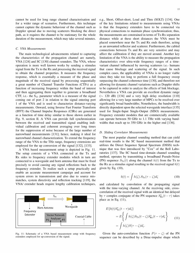
A VNA based measurement setup is depicted in Fig. 11.The setup consists of a VNA connected at the Tx andRx sides to frequency extender modules which in turn areconnected to a waveguide and horn antenna that must be fixedprecisely to avoid causing any signal reflections back to thefrequency extender. To realize such a setup practically andenable an accurate measurement campaign and account forsystem errors in transmission and also due to source mis-matches, system directivity and reflection tracking [119], theVNA/ extender heads require lengthy calibration techniques,
Fig. 11: Schematic of a VNA based measurement setup with frequencyextenders employed for up-conversion of the signal.
e.g., Short, Offset-short, Load and Thru (SOLT) [134]. Oneof the key limitations related to measurements using VNAsis that the frequency extenders have to be connected viaphysical connections to maintain phase synchronization; thus,the measurements are constrained in terms of Tx-Rx separationdistance while at these short distances the VNA must beplaced somewhere near the Tx and Rx ends therefore, actingas an unwanted reflector and scatterer. Furthermore, the cabledconnections between Tx and Rx are very sensitive and mayaffect the calibration if they are moved around. Another keylimitation of the VNA is the ability to measure the propagationcharacteristics over ultra-wide frequency ranges of a time-variant channel influenced by moving scatterers i.e.- humansthat cause blockage and scattering of the signal. In suchcomplex cases, the applicability of VNAs is no longer viablesince they take too long to perform a full frequency sweepsurpassing the channel coherence time [130], and therefore notallowing for dynamic channel variations such as Doppler shiftsto be captured in order to analyze the effects of link blockage.Nevertheless a VNA can provide an excellent dynamic range(∼ 120 dB) [134] and a very high delay resolution [110]allowing for a very large number of MPCs to be resolved oversignificantly broad bandwidths; Nonetheless, the bandwidth isdirectly dependent upon the selected waveguide interface [135]used for Single-Input Single-Output (SISO) measurements.Frequency extender modules that are commercially availablecan operate between 50 GHz to 1.1 THz with varying band-widths that reach up to 350 GHz in the higher end [136].
D. Sliding Correlator Measurements
The most popular channel sounding method that can yieldreal-time results is the SC based measurement method thatutilizes the Direct Sequence Spread Spectrum (DSSS) tech-nique that was first introduced by ”Cox” of the Bell Labo-ratories [137]. The SC based time-domain channel soundingmethod, operates by transmitting a broadband Pseudo-Noise(PN) sequence STx(t) along the channel h(t) from the Tx tothe Rx as a stimulus signal resulting to the received signal b(t)given by Eq. (10),
b(t) =
∫h(ζ).STx(τ − ζ)dζ (10)
and calculated by convolution of the propagating signalwith the time-varying channel. At the receiving side, cross-correlation of the received signal with an identical but delayedby τ complex conjugate of the PN sequence S∗
Rx(t− τ) takesplace as in Eq. (11),
E{b(t)S∗Tx(t− τ)dζ}
= E
{∫h(ζ)STx(t− ζ)S∗
Rx(t− τ)dζ
}=
∫h(ζ)S(τ − ζ)dζ.
(11)
Given the auto-correlation function P (τ − ζ) of the PNsequence can be described by a Dirac-impulse shape which
14
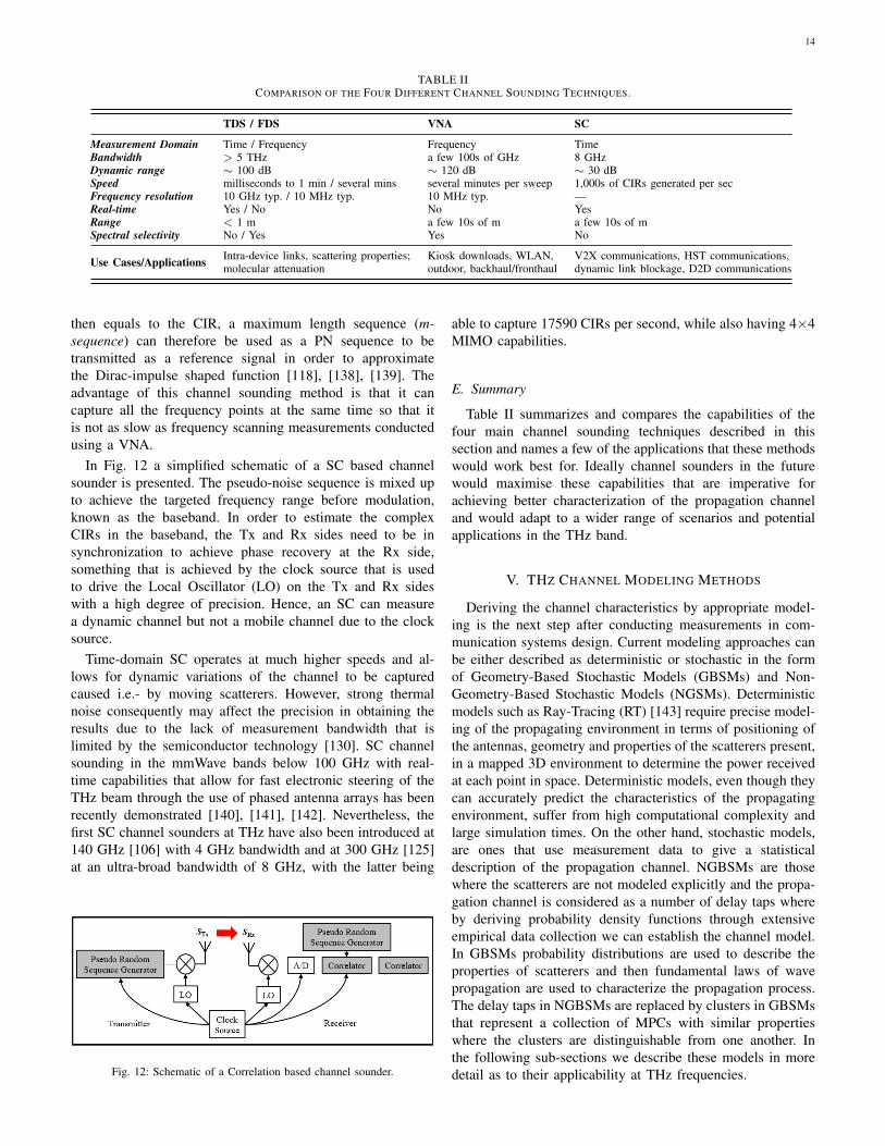
TABLE IICOMPARISON OF THE FOUR DIFFERENT CHANNEL SOUNDING TECHNIQUES.
TDS / FDS VNA SC
Measurement Domain Time / Frequency Frequency TimeBandwidth > 5 THz a few 100s of GHz 8 GHzDynamic range ∼ 100 dB ∼ 120 dB ∼ 30 dBSpeed milliseconds to 1 min / several mins several minutes per sweep 1,000s of CIRs generated per secFrequency resolution 10 GHz typ. / 10 MHz typ. 10 MHz typ. —Real-time Yes / No No YesRange < 1 m a few 10s of m a few 10s of mSpectral selectivity No / Yes Yes No
Use Cases/Applications Intra-device links, scattering properties;molecular attenuation
Kiosk downloads, WLAN,outdoor, backhaul/fronthaul
V2X communications, HST communications,dynamic link blockage, D2D communications
then equals to the CIR, a maximum length sequence (m-sequence) can therefore be used as a PN sequence to betransmitted as a reference signal in order to approximatethe Dirac-impulse shaped function [118], [138], [139]. Theadvantage of this channel sounding method is that it cancapture all the frequency points at the same time so that itis not as slow as frequency scanning measurements conductedusing a VNA.
In Fig. 12 a simplified schematic of a SC based channelsounder is presented. The pseudo-noise sequence is mixed upto achieve the targeted frequency range before modulation,known as the baseband. In order to estimate the complexCIRs in the baseband, the Tx and Rx sides need to be insynchronization to achieve phase recovery at the Rx side,something that is achieved by the clock source that is usedto drive the Local Oscillator (LO) on the Tx and Rx sideswith a high degree of precision. Hence, an SC can measurea dynamic channel but not a mobile channel due to the clocksource.
Time-domain SC operates at much higher speeds and al-lows for dynamic variations of the channel to be capturedcaused i.e.- by moving scatterers. However, strong thermalnoise consequently may affect the precision in obtaining theresults due to the lack of measurement bandwidth that islimited by the semiconductor technology [130]. SC channelsounding in the mmWave bands below 100 GHz with real-time capabilities that allow for fast electronic steering of theTHz beam through the use of phased antenna arrays has beenrecently demonstrated [140], [141], [142]. Nevertheless, thefirst SC channel sounders at THz have also been introduced at140 GHz [106] with 4 GHz bandwidth and at 300 GHz [125]at an ultra-broad bandwidth of 8 GHz, with the latter being
Fig. 12: Schematic of a Correlation based channel sounder.
able to capture 17590 CIRs per second, while also having 4×4MIMO capabilities.
E. Summary
Table II summarizes and compares the capabilities of thefour main channel sounding techniques described in thissection and names a few of the applications that these methodswould work best for. Ideally channel sounders in the futurewould maximise these capabilities that are imperative forachieving better characterization of the propagation channeland would adapt to a wider range of scenarios and potentialapplications in the THz band.
V. THZ CHANNEL MODELING METHODS
Deriving the channel characteristics by appropriate model-ing is the next step after conducting measurements in com-munication systems design. Current modeling approaches canbe either described as deterministic or stochastic in the formof Geometry-Based Stochastic Models (GBSMs) and Non-Geometry-Based Stochastic Models (NGSMs). Deterministicmodels such as Ray-Tracing (RT) [143] require precise model-ing of the propagating environment in terms of positioning ofthe antennas, geometry and properties of the scatterers present,in a mapped 3D environment to determine the power receivedat each point in space. Deterministic models, even though theycan accurately predict the characteristics of the propagatingenvironment, suffer from high computational complexity andlarge simulation times. On the other hand, stochastic models,are ones that use measurement data to give a statisticaldescription of the propagation channel. NGBSMs are thosewhere the scatterers are not modeled explicitly and the propa-gation channel is considered as a number of delay taps whereby deriving probability density functions through extensiveempirical data collection we can establish the channel model.In GBSMs probability distributions are used to describe theproperties of scatterers and then fundamental laws of wavepropagation are used to characterize the propagation process.The delay taps in NGBSMs are replaced by clusters in GBSMsthat represent a collection of MPCs with similar propertieswhere the clusters are distinguishable from one another. Inthe following sub-sections we describe these models in moredetail as to their applicability at THz frequencies.
15
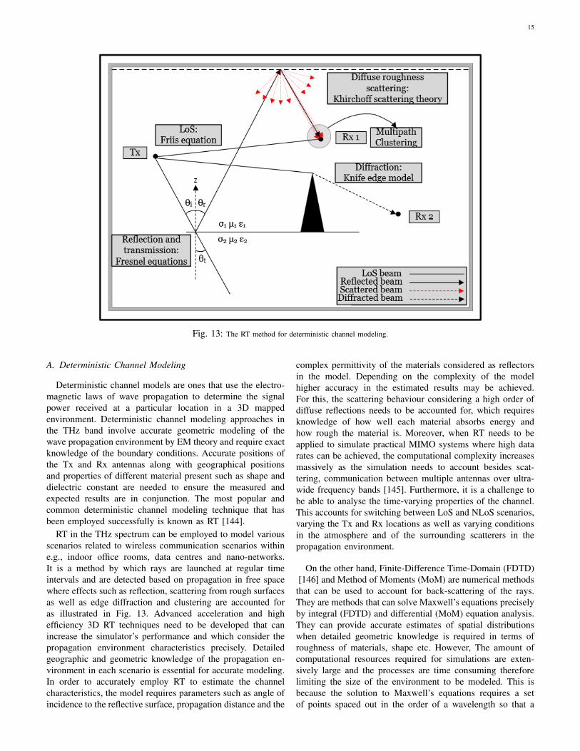
Fig. 13: The RT method for deterministic channel modeling.
A. Deterministic Channel Modeling
Deterministic channel models are ones that use the electro-magnetic laws of wave propagation to determine the signalpower received at a particular location in a 3D mappedenvironment. Deterministic channel modeling approaches inthe THz band involve accurate geometric modeling of thewave propagation environment by EM theory and require exactknowledge of the boundary conditions. Accurate positions ofthe Tx and Rx antennas along with geographical positionsand properties of different material present such as shape anddielectric constant are needed to ensure the measured andexpected results are in conjunction. The most popular andcommon deterministic channel modeling technique that hasbeen employed successfully is known as RT [144].
RT in the THz spectrum can be employed to model variousscenarios related to wireless communication scenarios withine.g., indoor office rooms, data centres and nano-networks.It is a method by which rays are launched at regular timeintervals and are detected based on propagation in free spacewhere effects such as reflection, scattering from rough surfacesas well as edge diffraction and clustering are accounted foras illustrated in Fig. 13. Advanced acceleration and highefficiency 3D RT techniques need to be developed that canincrease the simulator’s performance and which consider thepropagation environment characteristics precisely. Detailedgeographic and geometric knowledge of the propagation en-vironment in each scenario is essential for accurate modeling.In order to accurately employ RT to estimate the channelcharacteristics, the model requires parameters such as angle ofincidence to the reflective surface, propagation distance and the
complex permittivity of the materials considered as reflectorsin the model. Depending on the complexity of the modelhigher accuracy in the estimated results may be achieved.For this, the scattering behaviour considering a high order ofdiffuse reflections needs to be accounted for, which requiresknowledge of how well each material absorbs energy andhow rough the material is. Moreover, when RT needs to beapplied to simulate practical MIMO systems where high datarates can be achieved, the computational complexity increasesmassively as the simulation needs to account besides scat-tering, communication between multiple antennas over ultra-wide frequency bands [145]. Furthermore, it is a challenge tobe able to analyse the time-varying properties of the channel.This accounts for switching between LoS and NLoS scenarios,varying the Tx and Rx locations as well as varying conditionsin the atmosphere and of the surrounding scatterers in thepropagation environment.
On the other hand, Finite-Difference Time-Domain (FDTD)[146] and Method of Moments (MoM) are numerical methods
that can be used to account for back-scattering of the rays.They are methods that can solve Maxwell’s equations preciselyby integral (FDTD) and differential (MoM) equation analysis.They can provide accurate estimates of spatial distributionswhen detailed geometric knowledge is required in terms ofroughness of materials, shape etc. However, The amount ofcomputational resources required for simulations are exten-sively large and the processes are time consuming thereforelimiting the size of the environment to be modeled. This isbecause the solution to Maxwell’s equations requires a setof points spaced out in the order of a wavelength so that a
16
numerical solution to the equations can be found. This meansthat the computational complexity of the problem increasesmassively as the frequency and amount of scatterers increases.Both the FDTD and MoM approaches mentioned are veryattractive and may be combined with RT to provide a morereliable estimation method. Although; combining the two mod-els together may be quite challenging since they are devisedusing different tools and assumptions. Furthermore, large-scaleand small-scale interactions are tightly coupled and thus thehybrid model developed needs to consider mutual couplingbefore deployment. For the development of an efficient modelat THz, additional parameters need to be considered suchas polarization, indoor-to-outdoor propagation and channelvariations caused by moving scatterers [147].
B. Stochastic Channel Modeling
Stochastic channel models are ones that use empirical datato provide a statistical analysis of the channel by a spatio-temporal approach. These models are based on measurementcampaigns and require much less complexity in terms ofcomputing resource requirements compared to deterministicmodels. Although, measurement time to obtain good accuracyin the results is a limiting factor. Due to the higher orderfrequencies and larger bandwidths, wideband channels in theTHz regime require multipaths to be resolved in the timedomain. Narrow-band fading models such as Rayleigh andRicean may therefore no longer be required and a statisticalmodel that can generate the CIRs needs to be developed. Thiswould require us to obtain the spatio-temporal characteristicsof the propagation channel which are described in more detailas follows:
• Spatial Characteristics: Spatial parameters can be ex-tracted from a Power Angle Profile (PAP) that involvesstatistical distributions of the different multipaths inthe form of power received over AoA and AoD. PAPmeasurements can be conducted by varying a highlydirectional antenna in azimuth and elevation using highprecision rotational and translational stages and recordingthe power received with the advantage that no phaseinformation is required to steer the beam in the wanteddirection in contrast to electronic beam-steering [148].Misalignment of the antennas and signal arriving fromdifferent angles will cause power losses, and therefore itis important to know how much power is received at agiven point in time. Root Mean Square (RMS) angularspread is a spatial parameter that can be extracted fromthe PAP which describes the power arrival dispersedover the angles of incidence the antenna is being varied.Despite the high directivity of antennas at THz, thisangular spread may prove to be significant especially atlonger distances, i.e.- in an urban environment, wherespreads in the order of +/- 40◦ where recorded whenmeasured using a 30◦ beamwidth horn antenna [116].
• Temporal Characteristics: The temporal behavior of thechannel can be described in the form of a Power DelayProfile (PDP) which records power received over ToAof the different arriving MPCs where each component
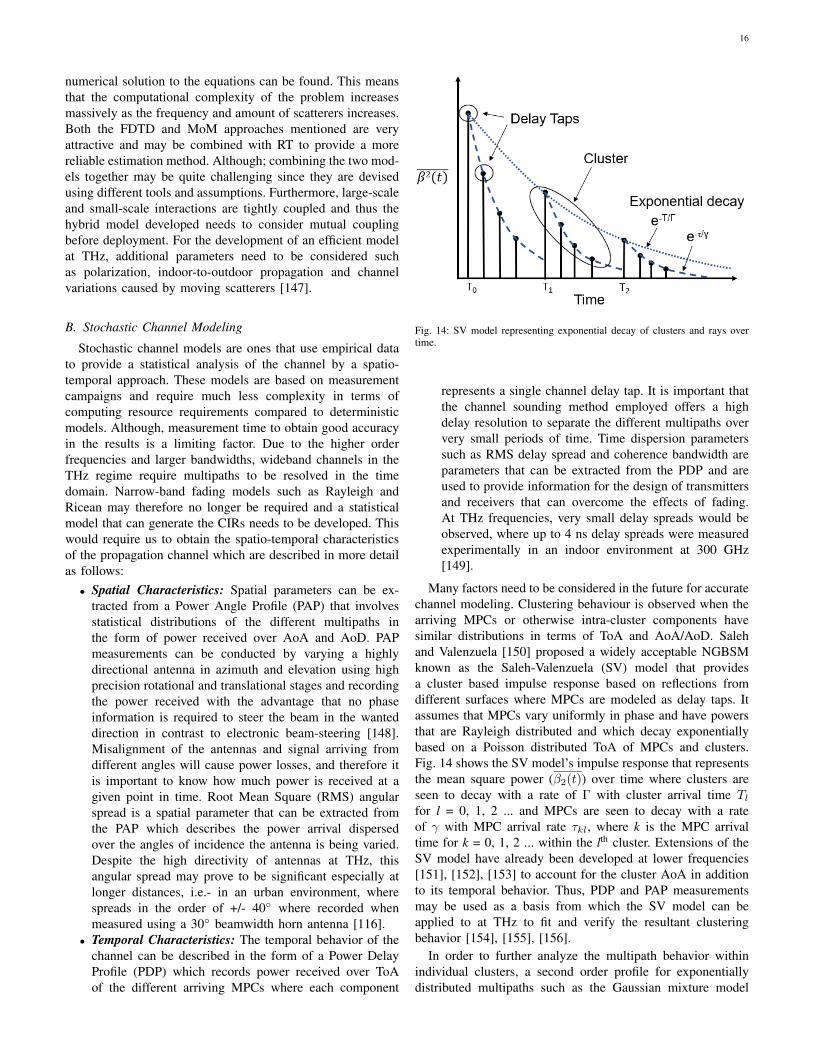
Fig. 14: SV model representing exponential decay of clusters and rays overtime.
represents a single channel delay tap. It is important thatthe channel sounding method employed offers a highdelay resolution to separate the different multipaths oververy small periods of time. Time dispersion parameterssuch as RMS delay spread and coherence bandwidth areparameters that can be extracted from the PDP and areused to provide information for the design of transmittersand receivers that can overcome the effects of fading.At THz frequencies, very small delay spreads would beobserved, where up to 4 ns delay spreads were measuredexperimentally in an indoor environment at 300 GHz[149].
Many factors need to be considered in the future for accuratechannel modeling. Clustering behaviour is observed when thearriving MPCs or otherwise intra-cluster components havesimilar distributions in terms of ToA and AoA/AoD. Salehand Valenzuela [150] proposed a widely acceptable NGBSMknown as the Saleh-Valenzuela (SV) model that providesa cluster based impulse response based on reflections fromdifferent surfaces where MPCs are modeled as delay taps. Itassumes that MPCs vary uniformly in phase and have powersthat are Rayleigh distributed and which decay exponentiallybased on a Poisson distributed ToA of MPCs and clusters.Fig. 14 shows the SV model’s impulse response that representsthe mean square power (β2(t)) over time where clusters areseen to decay with a rate of Γ with cluster arrival time Tl
for l = 0, 1, 2 ... and MPCs are seen to decay with a rateof γ with MPC arrival rate τkl, where k is the MPC arrivaltime for k = 0, 1, 2 ... within the lth cluster. Extensions of theSV model have already been developed at lower frequencies[151], [152], [153] to account for the cluster AoA in additionto its temporal behavior. Thus, PDP and PAP measurementsmay be used as a basis from which the SV model can beapplied to at THz to fit and verify the resultant clusteringbehavior [154], [155], [156].
In order to further analyze the multipath behavior withinindividual clusters, a second order profile for exponentiallydistributed multipaths such as the Gaussian mixture model
17
TxZ
Y
X
Z
X
Y
Rx
LoS Path
MPCs
Cluster i
Mean Ray
AoD
Mean Ray
AoA
Cluster k
Scatterer
Scatterer
Fig. 15: The cluster oriented GBSM.
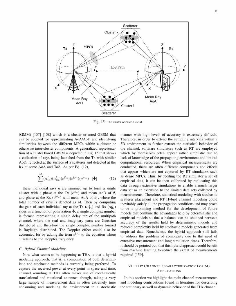
(GMM) [157] [158] which is a cluster oriented GBSM thatcan be adopted for approximating AoA/AoD and identifyingsimilarities between the different MPCs within a cluster orotherwise inter-cluster components. A generalized representa-tion of a cluster based GBSM is depicted in Fig. 15 that showsa collection of rays being launched from the Tx with similarAoD, reflected at the surface of a scatterer and detected at theRx at some AoA and ToA. As per Eq. (12),
M∑n
(α1Tx)(α
2Rx)(e
jθn)(ejϕn)(ejωα) [Φ] (12)
these individual rays n are summed up to form a singlecluster with a phase at the Tx (ejθn ) and mean AoD of θ,and phase at the Rx (ejϕn ) with mean AoA of ϕ , where thetotal number of rays is denoted as M. Then by computingthe gain of each individual ray at the Tx (α1
Tx) and Rx (α2Rx)
sides as a function of polarization Φ, a single complex numberis formed representing a single delay tap of the multipathchannel, where the real and imaginary parts are Gaussiandistributed and therefore the single complex number formedis Rayleigh distributed. The Doppler effect could also beaccounted for by adding the term ejωα to the equation whereω relates to the Doppler frequency.
C. Hybrid Channel Modeling
Now what seems to be happening at THz, is that a hybridmodeling approach, that is, a combination of both determin-istic and stochastic methods is currently being preferred. Tocapture the received power at every point in space and time,channel sounding at THz often makes use of mechanicallytranslational and rotational antennas; though, taking a verylarge sample of measurement data is often extremely timeconsuming and modeling the environment in a stochastic
manner with high levels of accuracy is extremely difficult.Therefore, in order to extend the sampling intervals within a3D environment to further extract the statistical behavior ofthe channel, software simulators such as RT are employedwhich by themselves often appear rather simplistic due tolack of knowledge of the propagating environment and limitedcomputational resources. When empirical measurements areconducted, there are often different components and effectsthat appear which are not captured by RT simulators suchas dense MPCs. Thus, by feeding the RT simulator a set ofempirical data, it can be then calibrated by replicating thisdata through extensive simulations to enable a much largerdata set as an extension to the limited data sets collected bymeasurements. Therefore, statistical modeling with stochasticscatterer placement and RT Hybrid channel modeling couldinevitably satisfy all the propagation conditions and may proveto be a promising method for the development of futuremodels that combine the advantages held by deterministic andempirical models so that a balance can be obtained betweenaccuracy of the results held by deterministic models andreduced complexity held by stochastic models generated fromempirical data. Nonetheless, the hybrid approach still failsto address the problem of complexity due to the need ofextensive measurement and long simulation times. Therefore,it should be pointed out, that this hybrid approach could benefitfrom machine learning to reduce the extent of measurementsrequired [159].
VI. THZ CHANNEL CHARACTERIZATION FOR 6GAPPLICATIONS
In this section we highlight the main channel measurementsand modeling contributions found in literature for describingthe stationary as well as dynamic behavior of the THz channel.
18
We categorize these models based on the application scenariosidentified in section III for future THz communications.
1) Kiosk/Desktop Downloads: Kiosk downloading may beconsidered as a short range communication scenario wherefile exchange between user devices such as smartphonesor PCs and ”vending” type machines can be pondered asprospective use cases with the potential to provide the socalled ”information showers” and achieve extremely high datarates targeting 100 Gbps [160]. Propagation in such use casesmay be assumed to be LoS over a short distance (< 1 m)with the uncertainty of user equipment antenna misalignmentwhere the user would have to essentially point the receivingdevice towards the transmitting end. The presence of a frontcover window would induce specular reflection while the Txside would have to be equipped with a high gain antenna tocompensate for propagation losses as antennas placed i.e.-within a smartphone would have their signal strength re-duced significantly because of the smartphone casing. Song etal. [161] presented a kiosk data downloading model based on aMMIC for the transmitter with Indium Phosphide (InP) basedHigh Electron Mobility Transistor (HEMT) semiconductortechnology along with concepts and considerations for smallpackaging for receiver modules based on the Low TemperatureCo-Fired Ceramic (LTCC) technologies, where 20 Gbps errorfree transmission was achieved over 1 m. This Kiosk down-loading system was further prototyped for operation at 300GHz and tested experimentally and a link budget plan was alsopresented [162]. He et al. [29], [163] presented a stochasticchannel model for 3 different Kiosk downloading scenarios at300 GHz where up to 6th order reflections were consideredand channel parameters were obtained based on measurementand calibrated ray-tracing results. Salhi et al. [164] investi-gated broadband angular channel characteristics by conductingmeasurements for 5 different frequency bands up to 321GHz for a short range indoor desktop download scenario thatcan be considered as a very similar use case to the kioskdownload scenario. Recently, short range characterization wasextended to carrier frequencies of 625 GHz with 250 GHzbandwidth to measure the channel properties in the the ultra-wideband [119], [110]. It was found that specular componentsfrom nearby scatterers are significant while reflections fromvarious materials can induce diffuse components that formclusters due to the high frequency selectivity at THz, whichnonetheless, is extremely unpredictable.
2) Data Center: A data center can be referred to as theinfrastructure within a building that contains racks with serverswith links connecting together the different racks as well as theservers within these racks [165]. A potential application of theTHz wave because of the high bandwidth availability is wire-less data center communications where the cabled connectionswould be replaced by ultra-fast and high data rate wirelesslinks. This would offer the advantages of flexibility and lowcosts as well as easier to maintain environmental conditionsprovided by cooling technologies for equipment operation.Cheng et al. [166] presented a THz MIMO channel soundingmeasurement campaign in a data centre like environmentat 300-312 GHz where LoS and Directed-NLoS (DNLoS)propagation were considered and the data was modeled in
the form of delay dispersion, shadowing gain and path loss.Similarly, an amplitude fading analysis and Doppler modelingwas considered for a 4×4 system, and a 2D geometricalmodel based on moving scatterers was also presented andvalidated with measurement data [167]. Characterization ofdifferent propagation phenomena for a wireless data centrewas considered in [30] while PAP and PDP measurements inan actual data centre were presented in [168] for various P2Pscenarios. In [169] a stochastic channel model was developedbased on the ray tracing approach that was used to derive thestatistical properties of the channel where up to 21 differentpaths with their associated delays and losses were consideredin the simulation along with dispersion effects caused byphase changes from small movement of the Tx and Rx. Anevaluation of the propagation channel in a THz wireless datacentre was presented in [170] where the effects of humiditywere considered. Finally, in [156] a cluster based model as amodification of the SV model was presented where the effectsof cooling on signal transmission were accounted for alongwith path loss and shadowing effects. The model was furthervalidated with measurement data.
3) Intra-Device: The continuous rise in data transfer withinmodern day devices where communications between compo-nents, different layers of motherboards and within on-chipnetworks are expected, has lead to complicated layout struc-tures, reduced processor space and high energy level consump-tion [171]. As such, high data rate intra-device THz wirelesscommunication links may prove to be a solution. The propa-gation environment to be considered for channel modeling isvery small, in the order of a few cm due to the casing of thedevice. The antenna requirements may be more flexible withless directive characteristics but communications are expectedto rely not only on LoS propagation but also by significantmultipath scattering contributions within the small enclosureby NLoS propagation. Examples of intra-device communi-cations include board-to-board, chip-to-chip [172], [31] aswell as in-chip communications [173], [174], [175]. Fu etal. [31], presented measurements conducted within a metalcasing at 300 GHz with the results showing that the receivedpower is sensitive to the heights of the Tx and Rx sides. In[176] characterization of transmission scenarios for THz intra-device communications was presented. Measurements wereconducted in the frequency range between 270-320 GHz withLoS and NLoS scenarios being considered where the narrowpropagation environment was found to induce less multipathcontribution while the impact of printed circuit boards wasfound to play a role in NLoS communication but has notbeen yet investigated in more detail. Data rates of 0.95 Tbpswere achieved by full-wave simulations in [177] for wirelesson-chip communications that interconnect cores in a multi-processor. In [178] the effects of multipath propagation on thelink budget due to multi-layer housing structures for on-chipcommunications were studied and may prove to be beneficialif careful chip layer structure is considered.
4) Backhaul/Fronthaul: Wireless backhaul/fronthaul linksare potential use cases for future THz communications withLoS as the main propagation characteristic. A backhaul linkis a fibre based or wireless link that connects the base station
19
to the core network and is in the km range. Current wirelessbackhaul links are not sufficient for future capacity and latencyrequirements and therefore a potential solution might be thatof THz wireless transmission as a wireless extension ofthe optical fiber between rural and highly populated urbanareas to ensure high-speed connectivity everywhere in a costeffective manner [179]. Fronthaul links can be used to givebroadband/high speed access to the end user when operatingat higher frequencies at places where the broadband customerdoes not have fiber connectivity and where the link distanceis much smaller compared to the backhaul. THz transmissioncan be applied to 5G fronthaul links in order to optimiseand speed up the implementation of 5G connectivity in urbanareas and thus; can provide more flexibility to avoid theexpensive fibre connections currently required for 5G systemdeployments. Automatic planning algorithms [32], [180] forthe backhaul/fronthaul links are essential in designing guide-lines for sucessfull deployment of these links. Planning forthese scenarios should involve identifying the shortest LoS linkwhere highly directive antennas that will minimize multipathpropagation will be employed. For terrestrial links we canassume that communications will be below the height ofclouds; however, the effect of attenuation due to fog may besignificant. The applicability and feasibility of such transmis-sion has already been proven by MMIC based technology anddemonstrated at large distances of 850 m at carrier frequenciesof 240 GHz where data rates of 64 Gbps were achieved [181].
5) WLAN: Typical indoor communications in the THzband will involve scenarios such as office rooms and confer-ence rooms. Such scenarios would have to consider LoS, linkblockage, and scattering as the main propagation phenomenaand will be mainly applied for interconnecting access pointsand not for user access. Notably, considering that the WiGig60 GHz standard [182] is of such limited range, then THzcannot be expected to go any further with communicationlinks ranging up to 20 metres. Calibrated RT simulations werepresented in [184] for indoor radio channels by taking accountdifferent frequency points within the evaluated range due tovarying propagation conditions and a novel calibrating methodwas employed that uses both spatial and temporal informationthat significantly improve the accuracy of the RT tool [185]and extend its applicability to much wider frequency ranges.The RT tool developed was built upon common image theoryfor reflections [186] and Kirchhoff scattering [187] analysisand the results were further validated against measurementdata collected at 300 GHz. Choi et al. in [188], proposed anovel GBSM for THz channels that mathematically describesthe specular component of a single induced cluster from indoorreflections that can be utilized when the main LoS componentis blocked. The model also accounts for the scattering loss andhas the advantage of reduced complexity in comparison to RT.The model was verified against a mirror-image procedure toaid in evaluating the physical characteristics and evaluate thesystem-level performance of the THz channels. In [189], RTsimulations were carried out in an indoor office room whereclustering due to multipath reflections from materials’ ofknown permittivity were identified and the effects of multipathpropagation on the PAP and PDP were considered. The effects
of clustering were validated against the SV model as they werefound to follow an exponential decay pattern.
In [190] RT modeling of short-range wireless communica-tions in a typical office environment was presented for theatmospheric windows below 1 THz. Statistical modeling wasconsidered in terms of AoA, AoD and ToA and Up to 4th
order reflections were considered in the simulation. It can bededuced that LoS components have the greatest contributionin received power while in the NLoS case the power receivedfrom reflections was much less, though it could supplementthe LoS when it is not available (e.g., due to blockage) but ahigh reliability communications system cannot be dependenton these components.
The effects of antenna misalignment on the received powerwill play a very important role at THz due to their highdirectivity, and as such, they are modeled as a random processin [191] where monte carlo simulations were used to evaluatethese effects while RT was used to determine the resolvablepaths and their associated gains and losses as a result ofpropagation in an indoor office room. Similarly, the effects ofdifferent antenna directivities on resolvable paths for differentapplications in terms of propagation losses, fading and delayspreads were investigated in [192] and it was found thatantenna directivities for fixed P2P applications should behigher than applications with positional uncertainty such ascommunications on board a desktop in the presence of non-stationary devices such as laptops where lower directivitiescould cater for antenna misalignment.
In [193] indoor channel measurements were conducted inthe recently standardised bands between 275-321 GHz for THzcommunications in a typical office scenario. Calibrated RT wasperformed, and a spatial and temporal analysis of the resultswas provided based on measurement data. MIMO channelcapacity was calculated for a 2×2 system where a capacity of6.21 bit/s/Hz was obtained. RT results were further comparedagainst measurement data and were found to be in goodagreement. Nonetheless; diffuse scattering was not consideredin the analysis. A modified version of the SV model used tocharacterize the THz channel for indoor THz communicationswith antenna sub-arrays operating at 300 GHz was presentedin [194]. An upper bound on the ergodic channel capacity wasobtained in relation to the number of antenna sub-arrays andas a function of distance where the capacity decreased with anincrease in the distance and the array gain decreased with theincrease in sub-array number. The ergodic channel capacity ata distance of 10 m with 40 antenna sub-arrays was found tobe 0.125 Tbps. Stochastic modeling of the indoor propagationchannel by considering both time and frequency domains [195]in a statistical analysis of ultra-wideband channels in the 275-325 GHz band was provided for a realistic office scenarioand the results were verified against calibrated RT simulations.The model accounts for AoA/AoD, ToA and phase togetherand considers channel dispersion for each resolvable path andso can be used to simulate practical MIMO systems. Angularspreads of a few degrees were observed while 3×3 MIMOcapacities ranging between 5.5-7.3 bit/s/Hz were measured.
Furthermore, Priebe et al. [196] conducted channel mea-surements at 300 GHz with a 10 GHz bandwidth. Mea-
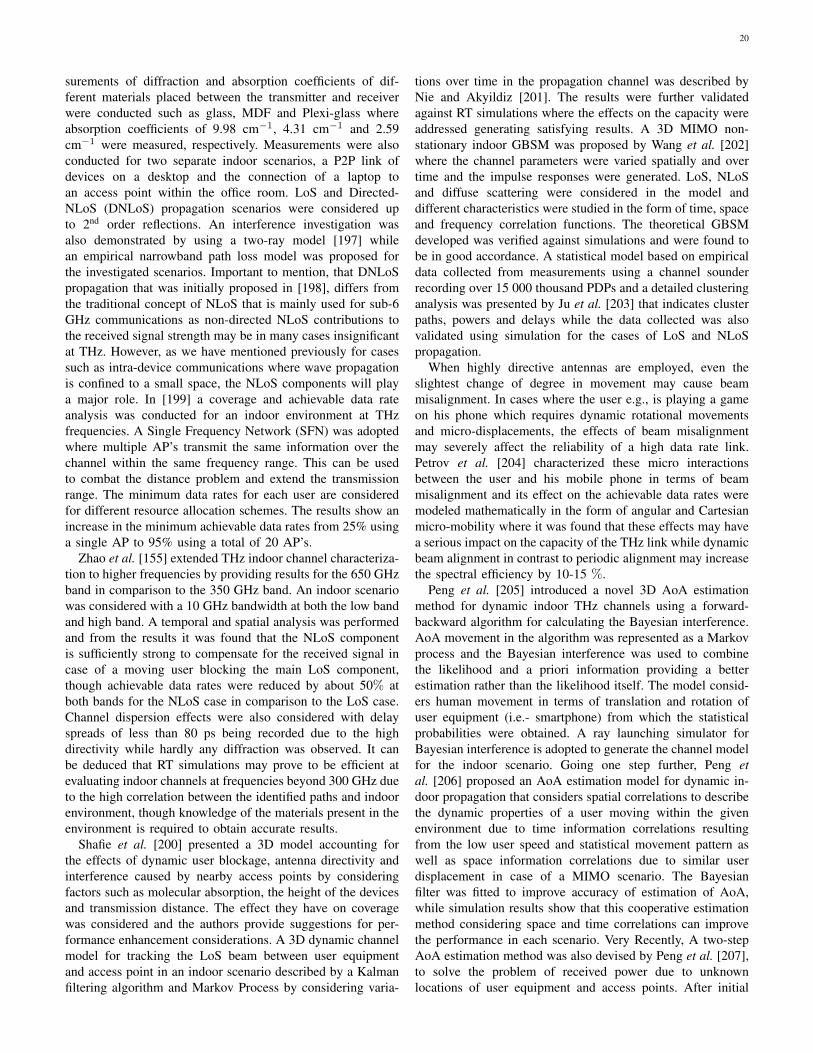
20
surements of diffraction and absorption coefficients of dif-ferent materials placed between the transmitter and receiverwere conducted such as glass, MDF and Plexi-glass whereabsorption coefficients of 9.98 cm−1, 4.31 cm−1 and 2.59cm−1 were measured, respectively. Measurements were alsoconducted for two separate indoor scenarios, a P2P link ofdevices on a desktop and the connection of a laptop toan access point within the office room. LoS and Directed-NLoS (DNLoS) propagation scenarios were considered upto 2nd order reflections. An interference investigation wasalso demonstrated by using a two-ray model [197] whilean empirical narrowband path loss model was proposed forthe investigated scenarios. Important to mention, that DNLoSpropagation that was initially proposed in [198], differs fromthe traditional concept of NLoS that is mainly used for sub-6GHz communications as non-directed NLoS contributions tothe received signal strength may be in many cases insignificantat THz. However, as we have mentioned previously for casessuch as intra-device communications where wave propagationis confined to a small space, the NLoS components will playa major role. In [199] a coverage and achievable data rateanalysis was conducted for an indoor environment at THzfrequencies. A Single Frequency Network (SFN) was adoptedwhere multiple AP’s transmit the same information over thechannel within the same frequency range. This can be usedto combat the distance problem and extend the transmissionrange. The minimum data rates for each user are consideredfor different resource allocation schemes. The results show anincrease in the minimum achievable data rates from 25% usinga single AP to 95% using a total of 20 AP’s.
Zhao et al. [155] extended THz indoor channel characteriza-tion to higher frequencies by providing results for the 650 GHzband in comparison to the 350 GHz band. An indoor scenariowas considered with a 10 GHz bandwidth at both the low bandand high band. A temporal and spatial analysis was performedand from the results it was found that the NLoS componentis sufficiently strong to compensate for the received signal incase of a moving user blocking the main LoS component,though achievable data rates were reduced by about 50% atboth bands for the NLoS case in comparison to the LoS case.Channel dispersion effects were also considered with delayspreads of less than 80 ps being recorded due to the highdirectivity while hardly any diffraction was observed. It canbe deduced that RT simulations may prove to be efficient atevaluating indoor channels at frequencies beyond 300 GHz dueto the high correlation between the identified paths and indoorenvironment, though knowledge of the materials present in theenvironment is required to obtain accurate results.
Shafie et al. [200] presented a 3D model accounting forthe effects of dynamic user blockage, antenna directivity andinterference caused by nearby access points by consideringfactors such as molecular absorption, the height of the devicesand transmission distance. The effect they have on coveragewas considered and the authors provide suggestions for per-formance enhancement considerations. A 3D dynamic channelmodel for tracking the LoS beam between user equipmentand access point in an indoor scenario described by a Kalmanfiltering algorithm and Markov Process by considering varia-
tions over time in the propagation channel was described byNie and Akyildiz [201]. The results were further validatedagainst RT simulations where the effects on the capacity wereaddressed generating satisfying results. A 3D MIMO non-stationary indoor GBSM was proposed by Wang et al. [202]where the channel parameters were varied spatially and overtime and the impulse responses were generated. LoS, NLoSand diffuse scattering were considered in the model anddifferent characteristics were studied in the form of time, spaceand frequency correlation functions. The theoretical GBSMdeveloped was verified against simulations and were found tobe in good accordance. A statistical model based on empiricaldata collected from measurements using a channel sounderrecording over 15 000 thousand PDPs and a detailed clusteringanalysis was presented by Ju et al. [203] that indicates clusterpaths, powers and delays while the data collected was alsovalidated using simulation for the cases of LoS and NLoSpropagation.
When highly directive antennas are employed, even theslightest change of degree in movement may cause beammisalignment. In cases where the user e.g., is playing a gameon his phone which requires dynamic rotational movementsand micro-displacements, the effects of beam misalignmentmay severely affect the reliability of a high data rate link.Petrov et al. [204] characterized these micro interactionsbetween the user and his mobile phone in terms of beammisalignment and its effect on the achievable data rates weremodeled mathematically in the form of angular and Cartesianmicro-mobility where it was found that these effects may havea serious impact on the capacity of the THz link while dynamicbeam alignment in contrast to periodic alignment may increasethe spectral efficiency by 10-15 %.
Peng et al. [205] introduced a novel 3D AoA estimationmethod for dynamic indoor THz channels using a forward-backward algorithm for calculating the Bayesian interference.AoA movement in the algorithm was represented as a Markovprocess and the Bayesian interference was used to combinethe likelihood and a priori information providing a betterestimation rather than the likelihood itself. The model consid-ers human movement in terms of translation and rotation ofuser equipment (i.e.- smartphone) from which the statisticalprobabilities were obtained. A ray launching simulator forBayesian interference is adopted to generate the channel modelfor the indoor scenario. Going one step further, Peng etal. [206] proposed an AoA estimation model for dynamic in-door propagation that considers spatial correlations to describethe dynamic properties of a user moving within the givenenvironment due to time information correlations resultingfrom the low user speed and statistical movement pattern aswell as space information correlations due to similar userdisplacement in case of a MIMO scenario. The Bayesianfilter was fitted to improve accuracy of estimation of AoA,while simulation results show that this cooperative estimationmethod considering space and time correlations can improvethe performance in each scenario. Very Recently, A two-stepAoA estimation method was also devised by Peng et al. [207],to solve the problem of received power due to unknownlocations of user equipment and access points. After initial
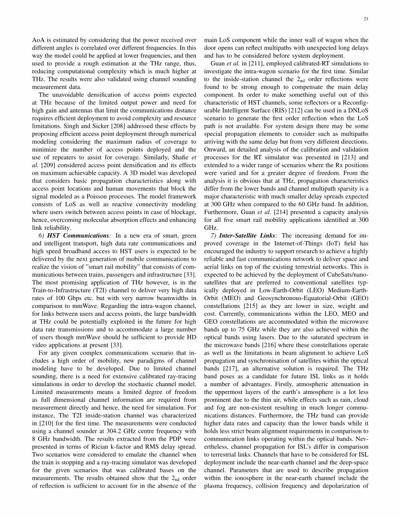
21
AoA is estimated by considering that the power received overdifferent angles is correlated over different frequencies. In thisway the model could be applied at lower frequencies, and thenused to provide a rough estimation at the THz range, thus,reducing computational complexity which is much higher atTHz. The results were also validated using channel soundingmeasurement data.
The unavoidable densification of access points expectedat THz because of the limited output power and need forhigh gain and antennas that limit the communications distancerequires efficient deployment to avoid complexity and resourcelimitations. Singh and Sicker [208] addressed these effects byproposing efficient access point deployment through numericalmodeling considering the maximum radius of coverage tominimize the number of access points deployed and theuse of repeaters to assist for coverage. Similarly, Shafie etal. [209] considered access point densification and its effectson maximum achievable capacity. A 3D model was developedthat considers basic propagation characteristics along withaccess point locations and human movements that block thesignal modeled as a Poisson processes. The model frameworkconsists of LoS as well as reactive connectivity modelingwhere users switch between access points in case of blockage,hence, overcoming molecular absorption effects and enhancinglink reliability.
6) HST Communications: In a new era of smart, greenand intelligent transport, high data rate communications andhigh speed broadband access to HST users is expected to bedelivered by the next generation of mobile communications torealize the vision of ”smart rail mobility” that consists of com-munications between trains, passengers and infrastructure [33].The most promising application of THz however, is in theTrain-to-Infrastructure (T2I) channel to deliver very high datarates of 100 Gbps etc. but with very narrow beamwidths incomparison to mmWave. Regarding the intra-wagon channel,for links between users and access points, the large bandwidthat THz could be potentially exploited in the future for highdata rate transmissions and to accommodate a large numberof users though mmWave should be sufficient to provide HDvideo applications at present [33].
For any given complex communications scenario that in-cludes a high order of mobility, new paradigms of channelmodeling have to be developed. Due to limited channelsounding, there is a need for extensive calibrated ray-tracingsimulations in order to develop the stochastic channel model.Limited measurements means a limited degree of freedomas full dimensional channel information are required frommeasurement directly and hence, the need for simulation. Forinstance, The T2I inside-station channel was characterizedin [210] for the first time. The measurements were conductedusing a channel sounder at 304.2 GHz centre frequency with8 GHz bandwidth. The results extracted from the PDP werepresented in terms of Rician k-factor and RMS delay spread.Two scenarios were considered to emulate the channel whenthe train is stopping and a ray-tracing simulator was developedfor the given scenarios that was calibrated bases on themeasurements. The results obtained show that the 2nd orderof reflection is sufficient to account for in the absence of the
main LoS component while the inner wall of wagon when thedoor opens can reflect multipaths with unexpected long delaysand has to be considered before system deployment.
Guan et al. in [211], employed calibrated-RT simulations toinvestigate the intra-wagon scenario for the first time. Similarto the inside-station channel the 2nd order reflections werefound to be strong enough to compensate the main delaycomponent. In order to make something useful out of thischaracteristic of HST channels, some reflectors or a Reconfig-urable Intelligent Surface (RIS) [212] can be used in a DNLoSscenario to generate the first order reflection when the LoSpath is not available. For system design there may be somespecial propagation elements to consider such as multipathsarriving with the same delay but from very different directions.Onward, an detailed analysis of the calibration and validationprocesses for the RT simulator was presented in [213] andextended to a wider range of scenarios where the Rx positionswere varied and for a greater degree of freedom. From theanalysis it is obvious that at THz, propagation characteristicsdiffer from the lower bands and channel multipath sparsity is amajor characteristic with much smaller delay spreads expectedat 300 GHz when compared to the 60 GHz band. In addition,Furthermore, Guan et al. [214] presented a capacity analysisfor all five smart rail mobility applications identified at 300GHz.
7) Inter-Satellite Links: The increasing demand for im-proved coverage in the Internet-of-Things (IoT) field hasencouraged the industry to support research to achieve a highlyreliable and fast communications network to deliver space andaerial links on top of the existing terrestrial networks. This isexpected to be achieved by the deployment of CubeSats/nano-satellites that are preferred to conventional satellites typ-ically deployed in Low-Earth-Orbit (LEO) Medium-Earth-Orbit (MEO) and Geosynchronous-Equatorial-Orbit (GEO)constellations [215] as they are lower in size, weight andcost. Currently, communications within the LEO, MEO andGEO constellations are accommodated within the microwavebands up to 75 GHz while they are also achieved within theoptical bands using lasers. Due to the saturated spectrum inthe microwave bands [216] where these constellations operateas well as the limitations in beam alignment to achieve LoSpropagation and synchronisation of satellites within the opticalbands [217], an alternative solution is required. The THzband poses as a candidate for future ISL links as it holdsa number of advantages. Firstly, atmospheric attenuation inthe uppermost layers of the earth’s atmosphere is a lot lessprominent due to the thin air, while effects such as rain, cloudand fog are non-existent resulting in much longer commu-nications distances. Furthermore, the THz band can providehigher data rates and capacity than the lower bands while itholds less strict beam alignment requirements in comparison tocommunication links operating within the optical bands. Nev-ertheless, channel propagation for ISL’s differ in comparisonto terrestrial links. Channels that have to be considered for ISLdeployment include the near-earth channel and the deep-spacechannel. Parameters that are used to describe propagationwithin the ionosphere in the near-earth channel include theplasma frequency, collision frequency and depolarization of
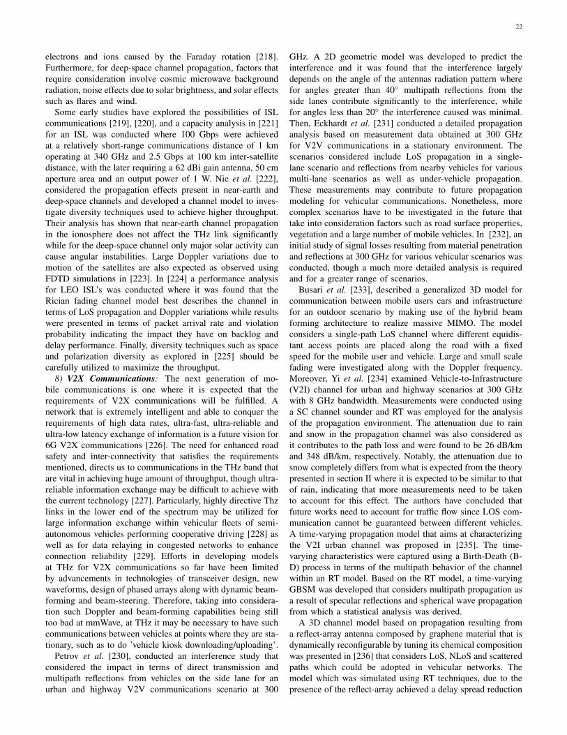
22
electrons and ions caused by the Faraday rotation [218].Furthermore, for deep-space channel propagation, factors thatrequire consideration involve cosmic microwave backgroundradiation, noise effects due to solar brightness, and solar effectssuch as flares and wind.
Some early studies have explored the possibilities of ISLcommunications [219], [220], and a capacity analysis in [221]for an ISL was conducted where 100 Gbps were achievedat a relatively short-range communications distance of 1 kmoperating at 340 GHz and 2.5 Gbps at 100 km inter-satellitedistance, with the later requiring a 62 dBi gain antenna, 50 cmaperture area and an output power of 1 W. Nie et al. [222],considered the propagation effects present in near-earth anddeep-space channels and developed a channel model to inves-tigate diversity techniques used to achieve higher throughput.Their analysis has shown that near-earth channel propagationin the ionosphere does not affect the THz link significantlywhile for the deep-space channel only major solar activity cancause angular instabilities. Large Doppler variations due tomotion of the satellites are also expected as observed usingFDTD simulations in [223]. In [224] a performance analysisfor LEO ISL’s was conducted where it was found that theRician fading channel model best describes the channel interms of LoS propagation and Doppler variations while resultswere presented in terms of packet arrival rate and violationprobability indicating the impact they have on backlog anddelay performance. Finally, diversity techniques such as spaceand polarization diversity as explored in [225] should becarefully utilized to maximize the throughput.
8) V2X Communications: The next generation of mo-bile communications is one where it is expected that therequirements of V2X communications will be fulfilled. Anetwork that is extremely intelligent and able to conquer therequirements of high data rates, ultra-fast, ultra-reliable andultra-low latency exchange of information is a future vision for6G V2X communications [226]. The need for enhanced roadsafety and inter-connectivity that satisfies the requirementsmentioned, directs us to communications in the THz band thatare vital in achieving huge amount of throughput, though ultra-reliable information exchange may be difficult to achieve withthe current technology [227]. Particularly, highly directive Thzlinks in the lower end of the spectrum may be utilized forlarge information exchange within vehicular fleets of semi-autonomous vehicles performing cooperative driving [228] aswell as for data relaying in congested networks to enhanceconnection reliability [229]. Efforts in developing modelsat THz for V2X communications so far have been limitedby advancements in technologies of transceiver design, newwaveforms, design of phased arrays along with dynamic beam-forming and beam-steering. Therefore, taking into considera-tion such Doppler and beam-forming capabilities being stilltoo bad at mmWave, at THz it may be necessary to have suchcommunications between vehicles at points where they are sta-tionary, such as to do ’vehicle kiosk downloading/uploading’.
Petrov et al. [230], conducted an interference study thatconsidered the impact in terms of direct transmission andmultipath reflections from vehicles on the side lane for anurban and highway V2V communications scenario at 300
GHz. A 2D geometric model was developed to predict theinterference and it was found that the interference largelydepends on the angle of the antennas radiation pattern wherefor angles greater than 40◦ multipath reflections from theside lanes contribute significantly to the interference, whilefor angles less than 20◦ the interference caused was minimal.Then, Eckhardt et al. [231] conducted a detailed propagationanalysis based on measurement data obtained at 300 GHzfor V2V communications in a stationary environment. Thescenarios considered include LoS propagation in a single-lane scenario and reflections from nearby vehicles for variousmulti-lane scenarios as well as under-vehicle propagation.These measurements may contribute to future propagationmodeling for vehicular communications. Nonetheless, morecomplex scenarios have to be investigated in the future thattake into consideration factors such as road surface properties,vegetation and a large number of mobile vehicles. In [232], aninitial study of signal losses resulting from material penetrationand reflections at 300 GHz for various vehicular scenarios wasconducted, though a much more detailed analysis is requiredand for a greater range of scenarios.
Busari et al. [233], described a generalized 3D model forcommunication between mobile users cars and infrastructurefor an outdoor scenario by making use of the hybrid beamforming architecture to realize massive MIMO. The modelconsiders a single-path LoS channel where different equidis-tant access points are placed along the road with a fixedspeed for the mobile user and vehicle. Large and small scalefading were investigated along with the Doppler frequency.Moreover, Yi et al. [234] examined Vehicle-to-Infrastructure(V2I) channel for urban and highway scenarios at 300 GHzwith 8 GHz bandwidth. Measurements were conducted usinga SC channel sounder and RT was employed for the analysisof the propagation environment. The attenuation due to rainand snow in the propagation channel was also considered asit contributes to the path loss and were found to be 26 dB/kmand 348 dB/km, respectively. Notably, the attenuation due tosnow completely differs from what is expected from the theorypresented in section II where it is expected to be similar to thatof rain, indicating that more measurements need to be takento account for this effect. The authors have concluded thatfuture works need to account for traffic flow since LOS com-munication cannot be guaranteed between different vehicles.A time-varying propagation model that aims at characterizingthe V2I urban channel was proposed in [235]. The time-varying characteristics were captured using a Birth-Death (B-D) process in terms of the multipath behavior of the channelwithin an RT model. Based on the RT model, a time-varyingGBSM was developed that considers multipath propagation asa result of specular reflections and spherical wave propagationfrom which a statistical analysis was derived.
A 3D channel model based on propagation resulting froma reflect-array antenna composed by graphene material that isdynamically reconfigurable by tuning its chemical compositionwas presented in [236] that considers LoS, NLoS and scatteredpaths which could be adopted in vehicular networks. Themodel which was simulated using RT techniques, due to thepresence of the reflect-array achieved a delay spread reduction
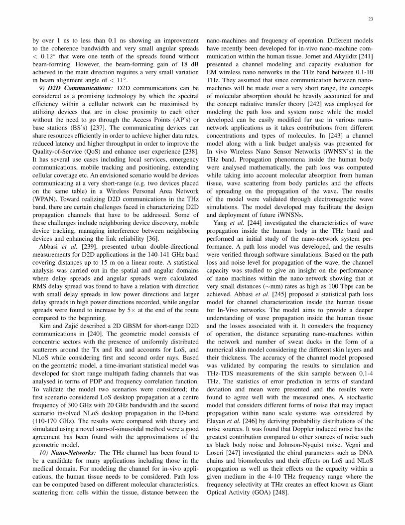
23
by over 1 ns to less than 0.1 ns showing an improvementto the coherence bandwidth and very small angular spreads< 0.12◦ that were one tenth of the spreads found withoutbeam-forming. However, the beam-forming gain of 18 dBachieved in the main direction requires a very small variationin beam alignment angle of < 11◦.
9) D2D Communications: D2D communications can beconsidered as a promising technology by which the spectralefficiency within a cellular network can be maximised byutilizing devices that are in close proximity to each otherwithout the need to go through the Access Points (AP’s) orbase stations (BS’s) [237]. The communicating devices canshare resources efficiently in order to achieve higher data rates,reduced latency and higher throughput in order to improve theQuality-of-Service (QoS) and enhance user experience [238].It has several use cases including local services, emergencycommunications, mobile tracking and positioning, extendingcellular coverage etc. An envisioned scenario would be devicescommunicating at a very short-range (e.g. two devices placedon the same table) in a Wireless Personal Area Network(WPAN). Toward realizing D2D communications in the THzband, there are certain challenges faced in characterizing D2Dpropagation channels that have to be addressed. Some ofthese challenges include neighboring device discovery, mobiledevice tracking, managing interference between neighboringdevices and enhancing the link reliability [36].
Abbasi et al. [239], presented urban double-directionalmeasurements for D2D applications in the 140-141 GHz bandcovering distances up to 15 m on a linear route. A statisticalanalysis was carried out in the spatial and angular domainswhere delay spreads and angular spreads were calculated.RMS delay spread was found to have a relation with directionwith small delay spreads in low power directions and largerdelay spreads in high power directions recorded, while angularspreads were found to increase by 5× at the end of the routecompared to the beginning.
Kim and Zajic described a 2D GBSM for short-range D2Dcommunications in [240]. The geometric model consists ofconcentric sectors with the presence of uniformly distributedscatterers around the Tx and Rx and accounts for LoS, andNLoS while considering first and second order rays. Basedon the geometric model, a time-invariant statistical model wasdeveloped for short range multipath fading channels that wasanalysed in terms of PDP and frequency correlation function.To validate the model two scenarios were considered; thefirst scenario considered LoS desktop propagation at a centrefrequency of 300 GHz with 20 GHz bandwidth and the secondscenario involved NLoS desktop propagation in the D-band(110-170 GHz). The results were compared with theory andsimulated using a novel sum-of-sinusoidal method were a goodagreement has been found with the approximations of thegeometric model.
10) Nano-Networks: The THz channel has been found tobe a candidate for many applications including those in themedical domain. For modeling the channel for in-vivo appli-cations, the human tissue needs to be considered. Path losscan be computed based on different molecular characteristics,scattering from cells within the tissue, distance between the
nano-machines and frequency of operation. Different modelshave recently been developed for in-vivo nano-machine com-munication within the human tissue. Jornet and Akyildiz [241]presented a channel modeling and capacity evaluation forEM wireless nano networks in the THz band between 0.1-10THz. They assumed that since communication between nano-machines will be made over a very short range, the conceptsof molecular absorption should be heavily accounted for andthe concept radiative transfer theory [242] was employed formodeling the path loss and system noise while the modeldeveloped can be easily modified fur use in various nano-network applications as it takes contributions from differentconcentrations and types of molecules. In [243] a channelmodel along with a link budget analysis was presented forIn vivo Wireless Nano Sensor Networks (iWNSN’s) in theTHz band. Propagation phenomena inside the human bodywere analysed mathematically, the path loss was computedwhile taking into account molecular absorption from humantissue, wave scattering from body particles and the effectsof spreading on the propagation of the wave. The resultsof the model were validated through electromagnetic wavesimulations. The model developed may facilitate the designand deployment of future iWNSNs.
Yang et al. [244] investigated the characteristics of wavepropagation inside the human body in the THz band andperformed an initial study of the nano-network system per-formance. A path loss model was developed, and the resultswere verified through software simulations. Based on the pathloss and noise level for propagation of the wave, the channelcapacity was studied to give an insight on the performanceof nano machines within the nano-network showing that atvery small distances (∼mm) rates as high as 100 Tbps can beachieved. Abbasi et al. [245] proposed a statistical path lossmodel for channel characterization inside the human tissuefor In-Vivo networks. The model aims to provide a deeperunderstanding of wave propagation inside the human tissueand the losses associated with it. It considers the frequencyof operation, the distance separating nano-machines withinthe network and number of sweat ducks in the form of anumerical skin model considering the different skin layers andtheir thickness. The accuracy of the channel model proposedwas validated by comparing the results to simulation andTHz-TDS measurements of the skin sample between 0.1-4THz. The statistics of error prediction in terms of standarddeviation and mean were presented and the results werefound to agree well with the measured ones. A stochasticmodel that considers different forms of noise that may impactpropagation within nano scale systems was considered byElayan et al. [246] by deriving probability distributions of thenoise sources. It was found that Doppler induced noise has thegreatest contribution compared to other sources of noise suchas black body noise and Johnson-Nyquist noise. Vegni andLoscri [247] investigated the chiral parameters such as DNAchains and biomolecules and their effects on LoS and NLoSpropagation as well as their effects on the capacity within agiven medium in the 4-10 THz frequency range where thefrequency selectivity at THz creates an effect known as GiantOptical Activity (GOA) [248].
24
11) General Models: In this part we present some note-worthy modeling contributions that target to extract the mainchannel characteristics at THz and which can adapt to a widerange of scenarios. Han et al. [249] presented a multi-ray de-terministic model that was developed based on RT techniquesfor the frequency range of 0.06-10 THz. A narrow-band modelwas initially created and the multi-ray model was formedbased on superposition of the sub-bands. A thorough analysison propagation effects such as LoS, scattering, diffraction,reflection and broadening effects along with common theorysuch as Kirchhoff scattering and knife edge diffraction wereemployed to analyze simulated results by varying the distanceand observing the frequency selectivity of the channel. RMSDelay spreads of 0.19 ns were found at 0.3 THz that droppedsignificantly to 51.7 ps at 0.7 THz over a 3 m distanceresulting to coherence bandwidths of 1.06 GHz and 3.87 GHzrespectively. The broadening effects were found to increasewith an increase in frequency because of the higher frequencyselectivity resulting from the short wavelength, hence, limitingthe achievable data rates. The wideband channel capacitywas also estimated over the 0.06-1 THz range using thewater-filling power allocation method to be 75 Gbps witha 10 dBm power at a 3 m distance. The simulated resultswere compared against experimental measurements found inliterature below 1 THz where some material properties are ac-cessible, though at higher frequencies the frequency selectivityis highly unpredictable to assume the validity of the model.Moldovan et al. [250] proposed an indoor channel model for0.1-10 THz considering LoS and NLoS propagation wherespecular as well as diffuse roughness components were con-sidered. The LoS component was found to be dominant eventhough at larger distances the NLoS component becomes moresignificant and in some cases dominant due to constructiveinterference between the indirect paths. Data rates of 1 Tbpswere simulated over a 1 m distance with a power of 1 W,while the capacity of just the NLoS component was foundto be 100 Gbps when modeled by a water-filling approachbetween 0.1-1 THz. Tsujimura et al. [251] illustrated a casualchannel model for the THz band. This work aimed to addressthe issue of deriving the impulse response from transmittanceby assuming linear phase that leads to a symmetric impulseresponse before and after the most significant LoS componentwhere it is not realistically possible for the signal to arrivebefore the main delay tap since it makes the model non-casual. The model developed can address this issue and wasvalidated with THz-TDS measurement data < 2 THz thatagree well with the results. A variation can be observed inthe coherence bandwidth obtained from the impulse responseas a function of the centre frequency that may be used todetermine the frequency selection for wireless communicationsystems. A generalised 3D THz channel model was presentedin [252] for 6G Ultra-Massive MIMO wireless communicationsystems that considered non-stationarities in the channel andand cluster evolution in frequency, space and time domainsand which can be applied for a variety of applications such asindoor, D2D communications.
12) Surface Roughness Modeling: Surface roughness is ameasure of the finely spaced micro-irregularities on the surface
texture which is composed of three components namely,roughness, waviness, and form [253]. The effect surfaceroughness will have on the scattering behavior depends on thesurface height relative to the wavelength. Factors that describethe roughness of a surface are the RMS height that allows fora fair comparison of the roughness of materials with similarstructures and correlation length which is the length from apoint on the surface to a short distance where the heights ofthe rough surface are correlated with each other.
In [254] rough surface scattering measurements were con-ducted in the low THz range for automotive radar applicationsat frequencies up to 1.1 THz. Back-scattering coefficients weremeasured and varied over the angle of incidence, to determinethe reflective properties of sandpaper of known permittivityat different grit levels. The backscattering coefficients weremeasured at frequency of 300 GHz over a bandwidth of 8GHz. The authors of the paper have deduced that by increasingthe frequency, the EM roughness of an individual surfacealso increases causing diffuse scattering and an increase inthe signal back-scattered from the road surface. In addition,the backscattering coefficient decreases significantly as theincidence angle increases. Furthermore, in [255] the authorsexamined the backscattering of EM signals at frequencies of300 GHz and 680 GHz with 4 GHz bandwidth from surfaceswith different roughness. The backscattering coefficients weremeasured for over a range of incident angles for different sam-ples of sandpaper of grit levels 50, 120 and 220. At 300 GHzthe backscattering from sandpaper with grits 120 and 220 werefound to be specular and the signal quickly decreased with theincrease in angle. At 680 GHz, backscattering from sandpaperswith grit 50 and grit 120 were diffuse, while backscatteringfrom sandpaper with grit 220 combines specular and diffusereflections.
In [256] the roughness parameters of metallic surfaceswere characterized using THz reflection spectra. Kirchhoff’sapproximation was used as a theoretical model and wascompared to the results obtained from measuring the reflectionspectra of aluminium using Fourier transform spectroscopy.The RMS roughness levels were measured, and a good agree-ment was found between the theoretical and experimentalresults. The reflectance measurements were made using aspectrometer while the RMS roughness was measured us-ing a stylus surface profilometer. The range of frequenciesconsidered in the experiment varied between 0.3 to 3 THz.The results were presented in terms of reflectance and wave-number where the RMS roughness curve was compared to theGaussian fit.
In [257] a theoretical and empirical evaluation of the effectssub-micrometer roughness has on the effective conductivity inthe THz regime was presented. Two frequency ranges wereconsidered at 400 and 650 GHz that were achieved using anopen quasi-optical resonator where the THz waves are usuallyincident to the sample. The statistical analysis performed usingthe measurement data was validated using two closed-formmodels and a finite-element simulation. It was found thatthe Mie-scattering based and finite element approaches aremore accurate for smoother samples relative to the skin depth.For surface considerations greater than the skin depth it was
25
found that the Hammerstad and Bekkadal models providemore accurate predictions of effective conductivity. The resultspresented in this paper can be set as benchmark for new andimproved models of effective conductivity in the THz regime.
In [258] the influence of surface roughness on THz re-flection measurements is considered. This paper aimed atproviding an insight in the performance of THz TDS for thedetection of hazardous substances for security applications.The measurements undertaken involve smooth and roughmetallic and dielectric surfaces varied over angle of incidenceand degree of surface roughness (grit). A Maitai femto-secondlaser in a THz-TDS setup was employed for the measurements.The frequency range considered was 0.1-3.0 THz and theresults were validated based on radar theory.
In [259] a study was performed to provide an insightto the different measurements conducted used to determinethe properties of different material in the THz channel. Theabsorption coefficient and the refractive index were calculatedfor the frequency range of 70 to 110 GHz. Surface roughnessmeasurements were also performed for frequencies beyond100 GHz (up to 410 GHz) to predict reflection and scatteringof the wave more accurately by using equipment available foroptical 3D micro and nano-metrology [260].
In [261] rough surface scattering was investigated for bothindoor and outdoor scenarios at carrier frequencies of 100,200, 300 and 400 GHz. NLOS and LOS scenarios are con-sidered based on signal reflections from building walls. TheBit Error Rate (BER) performance was measured relative tothe output power. It was shown that the losses caused byscattering off the rough surface of the walls were much lessthan the losses caused by absorption at all measured carrierfrequencies, while the losses caused by absorption were seento increase with frequency. To achieve error-free transmissionthe transmitted power needs to be higher to account forabsorption and scattering.
A. Summary for 6G Channel Modeling Efforts
Table III summarizes and compares the most importantscenario-specific modeling contributions found in literature.Since channel models in the THz band mainly rely on channelmeasurements, many more measurement campaigns must beundertaken in order to realize 6G applications and make useof the vastly available spectrum between 0.1-3.0 THz forfuture communication systems design. Having a closer look,we can deduce that these efforts lack characterization of thechannel particularly above 300 GHz and are quite sparsefor some of the envisioned applications. Furthermore, it isobvious that there is a lack of sounding equipment with MIMOcapabilities that are imperative for realizing long distancecommunications and achieving high throughput levels. A morethorough analysis regarding requirements of future channelmodeling efforts follows in section VII.
VII. CHALLENGES AND FUTURE RESEARCH DIRECTIONS
A. Open Issues and Challenges
From the work analyzed in this survey paper, there are someopen issues and challenges in modeling techniques that need
to be improved upon while other future research directions areset.
1) Diffuse Particle Scattering: Models such as R-R andB-K that are used to characterize scattering from materialsurfaces may no longer be applicable and therefore requirefurther consideration at THz. The R-R model while it performswell at predicting scattering from various angles at generallysmooth surfaces and takes into consideration polarization ofthe waves, it fails doing the same for rough surfaces. On theother hand, the B-K model performs better for rough surfacesbut is not as effective at wider angles due to effects suchas absorption and shadowing, while it does not account foreffects such as polarization [262]. Also very important at THzis that there is a very thin Fresnel zone. When different echoesarrive but the Fresnel zone is blocked by scatterers, this causesquite separate specular rather than diffuse reflections of somerough surfaces as diffuse scattering happens where the tip ofthe Fresnel zone is incident on the rough surface. This is animportant characteristic that opens up more work.
2) Atmospheric Channel Dispersion: Atmospheric GroupVelocity Dispersion (GVD) is a broadening effect observed inTHz atmospheric channels which can affect significantly themaximum achievable data transmission rates [263]. GVD isa measure of how different channels, media may affect theduration of the pulse propagating through them. As the THzchannel is dominated by atmospheric effects such as watervapor, the resonances occurring within the water particlesintroduce GVD due to different frequency components prop-agating at different velocities. Another property that requiresconsideration are the Doppler shifts that may also cause thebroadening of THz pulses in presence of moving scattererswithin a multipath environment and is extremely importantwhen modeling radar sensing applications such as vehicletracking [264]. Since the THz channel is highly frequency se-lective, GVD is caused leading to a distortion and broadeningof the pulse waveform along with Inter-Symbol Interference(ISI). Factors that may limit transmission rates and cause GVDthat need to be explored further include link distance, watervapor density and channel bandwidth. In [265] a novel methodis developed for compensating atmospheric channel dispersionfor THz wireless communication using a cohort of stratifiedmedia reflectors.
3) Capturing Time-Varying Channel Characteristics: Sofar channel characterization was mainly focused on staticscenarios where P2P links will be employed. But in realitymost cases will have to adapt to dynamic variations of thechannel characteristics due to the highly directive character-istic of the THz waves. Link blockage will be a major issue,especially when planning for deployment of THz communi-cations in scenarios where the presence of moving scattererswould affect coverage massively or in scenarios where dualmobility is involved when two devices are communicatingwith each other, i.e.- D2D communications. Moreover, inmore advanced cases, i.e.- two vehicles communicating witheach other, where both the Tx and Rx side are movingand at very high speeds, significant channel variations wouldoccur continuously and large Doppler shifts would have tobe accounted for over extremely short periods of time. With
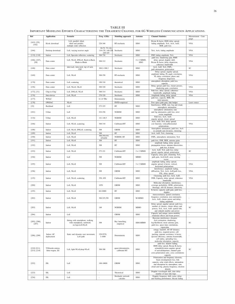
26
TABLE IIIIMPORTANT MODELING EFFORTS CHARACTERIZING THE TERAHERTZ CHANNEL FOR 6G WIRELESS COMMUNICATION APPLICATIONS.
Ref Application Scenario Freq. (GHz) Modeling approach Antenna Channel Statistics Measurement Cam-paign
[163], [29],[162] Kiosk download
LoS, parallel, tilted,tilted and parallel,
multiple order reflection220-340 RT-stochastic SISO
Rician K-factor, RMS delay spread,fading amplitude, ToA, AoA, AoD,
BER, path lossVNA
[164] Desktop download LoS, varying receiver angle50-75, 75-110,
110-170, 140-220,220-325
Stochastic SISO ToA, AoA, fading amplitude VNA
[119], [110] Indoor LoS, Specular reflection, scattering 500-750 Stochastic SISO PDP, fading amplitude, ToA VNA
[166], [167],[30] Data center
LoS, NLoS, DNLoS, Rack-to-Rack,Blade-to-Blade 300-312 Stochastic
4×4 MIMO,SISO
path loss, shadowing gain, RMSdelay spread, doppler shift,
Rician K-factor, delay dispersion,coherence bandwidth
VNA
[168] Data centerinter-rack, intra-rack, top of rack,
P2P 300.2–308.2 Stochastic SISOAoA, AoD, ToA, FSPL,
path attenuation, polarization SC
[169] Data center LoS, NLoS 300-350 RT-stochastic SISO
Delay spread, angular spread,amplitude fading, PL-angle correlation,
PL-delay correlation, phase andfrequency dispersion
VNA
[170] Data center LoS, scattering 190-310 theoretical SISOatmospheric absorption, path loss,
capacity -
[156] Data center LoS, NLoS, OLoS 300-320 Stochastic SISODelay spread, path loss, cluster powers,
shadowing gain, correlation VNA
[172], [31] Chip-to-Chip LoS, DNLoS, NLoS 300-314 Stochastic SISOPath loss, delay spread, coherence
bandwidth, amplitude fading VNA
[176] Intra-device LoS, NLoS 270-320 Stochastic SISO Amplitude fading, delay spread VNA
[177] WiNoC 0-1.0 THz Deterministicpath loss, capacity, BER, ISI,
field intensity -
[178] OWiNoC NLoS FDTD-empirical Free space path gain, link budget Laser source
[32] Backhaul LoS 275-325 RT SISOInterference, SINR, rain, fog and cloud,
atmospheric attenuation -
[181] Urban LoS 224-256 NGBSM SISOatmospheric attenuation, rain
and fog attenuation, path loss, errorvector magnitude
-
[116] Urban LoS, NLoS 141-148.5 NGBSM SISOPath loss, AoA, AoD,
angular spread, cluster spread
[184] Indoor LoS, NLoS, scattering 300-310 Calibrated-RT SISOAoA, AoD, ToA, delay spread,cost function, vertical/horizontal
polarizations.VNA
[188] Indoor LoS, NLoS, DNLoS, scattering 300 GBSM SISOAtmospheric attenuation, path loss, AoA
in azimuth and elevation, clustering -
[189] Indoor LoS, NLoS 300 RT SISO AoA, AoD, ToA, clustering -
[190] Indoor LoS, NLoS300,350,410,
670,850 NGBSM, RT SISO FSPL, atmospheric attenuation, ToA -
[191] Indoor LoS, NLoS 300 RT SISO path loss, SNR, BER, antenna gains -
[192] Indoor LoS, NLoS 300 RT SISOamplitude fading, delay spread,
propagation losses, antenna directivities,path loss, k-factor
-
[193] Indoor LoS, NLoS 275-321 Calibrated-RT 2×2 MIMOAoA, AoD, ToA, path loss, delay
spread, angular spread, polarization SC
[194] Indoor LoS 300 NGBSM MIMOCapacity, array gain, clustering, ToA,path gain, AoA/AoD, array steering
vector-
[195] Indoor LoS, NLoS 300 Calibrated-RT 3×3 MIMOamplitude fading, delay spread,
angular spread, k-factor, vertical,horizontal polarizations
VNA
[196] Indoor LoS, NLoS 300 GBSM SISOInterference, amplitude fading,
diffraction, ToA, AoA, AoD,path loss,FSL, delay spread
VNA
[155] Indoor LoS, NLoS, scattering 350, 650 Calibrated-RT SISOClustering, path loss, AoA, AoD,
SNR, Capacity, delay spread, coherencebandwidth
VNA
[200] Indoor LoS, NLoS 1070 GBSM SISOMolecular absorption, interference,
coverage probability, SINR, polarization,blockage, AP-UE distance, directivity
-
[195] Indoor LoS, NLoS 60-10000 RT SISOK-factor, capacity, path gain, path loss,
doppler -
[202] Indoor LoS, NLoS 300,325,350 GBSM M-MIMO
Autocorrelation, spatial correlation,frequency correlation, non-stationarity,AoA, AoD, cluster power and delay,
fading amplitude
-
[203] Indoor LoS, NLoS 140 NGBSM MIMO
Delay spread, angular spread, path loss,number of clusters, cluster delays andpowers, ToA, AoA, AoD, spatial lobe
and subpath number and power
SC
[204] Indoor LoS - GBSM SISOCapacity and outage, micro-mobilityrotational effects and beam powers -
[205], [206],[207] Indoor
Sitting with smartphone, walkingwith smartphone, notebook
on legs,LoS,NLoS300
Ray launching,empirical SISO,MIMO
Bayesian interference, dynamicAoA estimation, shadowing,
log-likelihood, mean antenna gain,path loss, space-time correlations,
eigenvalue
SC
[208], [209]Indoor APdeployment
Static and dynamic user movement,LoS path
320-9570,1-1080 Deterministic SISO
outage, handoff, AP-AP distance,path loss, required power, cell
packing, repeater assistance, k-factor,spectral efficiency, antenna beamwidth,
cell radius, spreading loss,molecular absorption, capacity
-
[210] [211],[213], [214]
T2I/inside-station,Intra-wagon, I2I LoS, light-NLoS,deep-NLoS 300-308
quasi-deterministic,calibrated RT SISO
path loss, shadow fading,RMS delay spread, Rician K-factor,
azimuth/elevation angular spreadof arrival/departure, channel gain
cross-polarization ratio, cross correlationscapacity
SC
[222] ISL LoS 100-10000 GBSM SISO
Polarization and frequency diversity,beam misalignment loss, link
capacity, solar wind effects, attenuationand absorption by atmosphere, rain,
cloud and fog, plasma frequency, electrondensity
-
[223] ISL LoS - Theoretical SISODoppler wavelength shift, time delay
number of laser link hops -
[224] ISL LoS -Stochastic network
calculus SISODoppler frequency shift, noise, delay
and backlog performance, Rician fading -
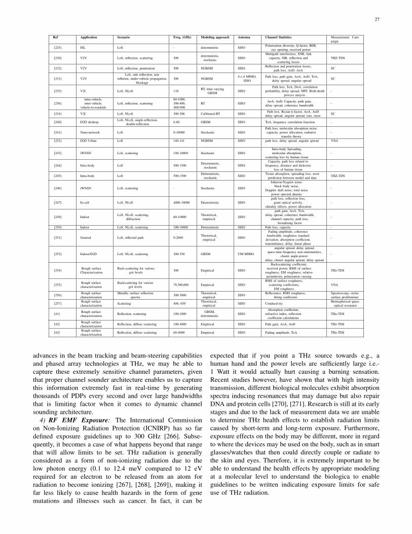
27
Ref Application Scenario Freq. (GHz) Modeling approach Antenna Channel Statistics Measurement Cam-paign
[225] ISL LoS - deterministic SISOPolarization diversity, Q-factor, BER,
eye opening, received power
[230] V2V LoS, reflection, scattering 300deterministic,
stochastic SISOMultipath interference, SNR, link
capacity, SIR, reflection andscattering losses
THZ-TDS
[232] V2V LoS, reflection, penetration 300 NGBSM SISOReflection and penetration losses,
path loss, AoD, AoA SC
[231] V2VLoS, side reflection, rear
refletion, under-vehicle propagation,blockage
300 NGBSM4×4 MIMO,
SISOPath loss, path gain, AoA, AoD, ToA,
delay spread, angular spread SC
[235] V2I LoS, NLoS 110RT, time-varying
GBSM SISOPath loss, ToA, DoA, correlation
probability, delay spread, MPC Birth-deathprocess anaysis.
-
[236]intra-vehicle,inter-vehicle,
vehicle-to-roadsideLoS, reflection, scattering
60-1000,300-400,800-900
RT SISOAoA, AoD, Capacity, path gain,
delay spread, coherence bandwidth -
[234] V2I LoS, NLoS 300-308 Calibrated-RT SISOPath loss, Rician k-factor, AoA, AoD
delay spread, angular spread, rain, snow SC
[240] D2D desktopLoS, NLoS, single-reflection,
double-reflection 0-60 GBSM SISO ToA, frequency correlation function -
[241] Nano-network LoS 0-10000 Stochastic SISOPath loss, molecular absorption noise,capacity, power allocation, radiative
transfer theory-
[252] D2D Urban LoS 140-141 NGBSM SISO path loss, delay spread, angular spread VNA
[243] iWNSN LoS, scattering 100-10000 Stochastic SISOIntra-body Spreading,molecular absorption,
scattering loss by human tissue-
[244] Intra-body LoS 500-1500Deterministic,
stochastic SISOCapacity, path loss related to
frequency, distance and dielectricloss of human tissue
-
[245] Intra-body LoS 500-1500Deterministic,
stochastic SISOTissue absorption, spreading loss, error
prediction between model and data THZ-TDS
[246] iWNSN LoS, scattering - Stochastic SISO
Johnson-Nyquist noise,black body noise,
Doppler shift noise, total noisepower spectral density
-
[247] In-cell LoS, NLoS 4000-10000 Deterministic SISOpath loss, reflection loss,
giant optical activity,chirality effects, power allocation
-
[249] IndoorLoS, NLoS, scattering,
diffraction 60-10000Theoretical,
empirical SISO
path gain, AoA, ToA,delay spread, coherence bandwidth,
channel capacity, path loss,broadening factor
-
[250] Indoor LoS, NLoS, scattering 100-10000 Deterministic SISO Path loss, capacity -
[251] General LoS, reflected path 0-2000Theoretical,
empirical SISO
Fading amplitude, coherencebandwidth, roughness standard
deviation, absorption coefficient,transmittance, delay, linear phase
-
[252] Indoor/D2D LoS, NLoS, scattering 300-350 GBSM UM-MIMO
angular spread, delay spread,space-time-frequency non-stationarities,
cluster angle-power-delay, cluster angular spread, delay spread
-
[254]Rough surface
CharacterizationBack-scattering for various
grit levels 300 Empirical SISO
Backscattering coefficient,received power, RMS of surface
roughness, EM roughness, relativepermittivity, polarization varying
THz-TDS
[255]Rough surfacecharacterization
Backscattering for variousgrit levels 79,300,680 Empirical SISO
RMS of surface roughness,scattering coefficients,
EM roughnessVNA
[256]Rough surfacecharacterization
Metallic surface reflectionspectra 300-3000
Theoretical,empirical SISO
Reflectance, RMS roughness,fitting coefficient
Spectroscopy, stylussurface profilometer
[257]Rough surfacecharacterization Scattering 400, 650
Theoretical,empirical SISO Conductivity
Hemispherical quasi-optical resonator
[41]Rough surfacecharacterization Reflection, scattering 100-1000
GBSM,deterministic SISO
Absorption coefficient,refractive index, reflection
coefficient calculationsTHz-TDS
[42]Rough surfacecharacterization Reflection, diffuse scattering 100-4000 Empirical SISO Path gain, AoA, AoD THz-TDS
[43]Rough surfacecharacterization Reflection, diffuse scattering 60-4000 Empirical SISO Fading amplitude, ToA THz-TDS
advances in the beam tracking and beam-steering capabilitiesand phased array technologies at THz, we may be able tocapture these extremely sensitive channel parameters, giventhat proper channel sounder architecture enables us to capturethis information extremely fast in real-time by generatingthousands of PDPs every second and over large bandwidthsthat is limiting factor when it comes to dynamic channelsounding architecture.
4) RF EMF Exposure: The International Commissionon Non-Ionizing Radiation Protection (ICNIRP) has so fardefined exposure guidelines up to 300 GHz [266]. Subse-quently, it becomes a case of what happens beyond that rangethat will allow limits to be set. THz radiation is generallyconsidered as a form of non-ionizing radiation due to thelow photon energy (0.1 to 12.4 meV compared to 12 eVrequired for an electron to be released from an atom forradiation to become ionizing [267], [268], [269]), making itfar less likely to cause health hazards in the form of genemutations and illnesses such as cancer. In fact, it can be
expected that if you point a THz source towards e.g., ahuman hand and the power levels are sufficiently large i.e.-1 Watt it would actually hurt causing a burning sensation.Recent studies however, have shown that with high intensitytransmission, different biological molecules exhibit absorptionspectra inducing resonances that may damage but also repairDNA and protein cells [270], [271]. Research is still at its earlystages and due to the lack of measurement data we are unableto determine THz health effects to establish radiation limitscaused by short-term and long-term exposure. Furthermore,exposure effects on the body may be different, more in regardto where the devices may be used on the body, such as in smartglasses/watches that then could directly couple or radiate tothe skin and eyes. Therefore, it is extremely important to beable to understand the health effects by appropriate modelingat a molecular level to understand the biologica to enableguidelines to be written indicating exposure limits for safeuse of THz radiation.
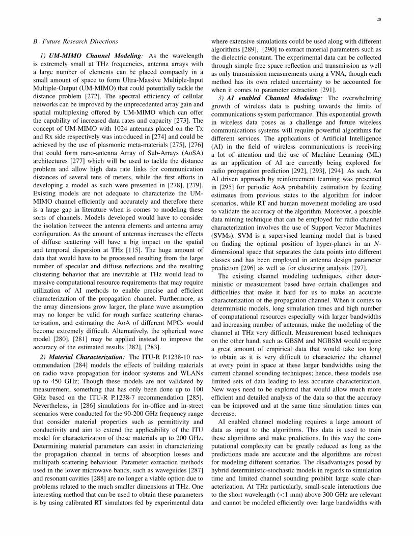
28
B. Future Research Directions
1) UM-MIMO Channel Modeling: As the wavelengthis extremely small at THz frequencies, antenna arrays witha large number of elements can be placed compactly in asmall amount of space to form Ultra-Massive Multiple-InputMultiple-Output (UM-MIMO) that could potentially tackle thedistance problem [272]. The spectral efficiency of cellularnetworks can be improved by the unprecedented array gain andspatial multiplexing offered by UM-MIMO which can offerthe capability of increased data rates and capacity [273]. Theconcept of UM-MIMO with 1024 antennas placed on the Txand Rx side respectively was introduced in [274] and could beachieved by the use of plasmonic meta-materials [275], [276]that could form nano-antenna Array of Sub-Arrays (AoSA)architectures [277] which will be used to tackle the distanceproblem and allow high data rate links for communicationdistances of several tens of meters, while the first efforts indeveloping a model as such were presented in [278], [279].Existing models are not adequate to characterize the UM-MIMO channel efficiently and accurately and therefore thereis a large gap in literature when is comes to modeling thesesorts of channels. Models developed would have to considerthe isolation between the antenna elements and antenna arrayconfiguration. As the amount of antennas increases the effectsof diffuse scattering will have a big impact on the spatialand temporal dispersion at THz [115]. The huge amount ofdata that would have to be processed resulting from the largenumber of specular and diffuse reflections and the resultingclustering behavior that are inevitable at THz would lead tomassive computational resource requirements that may requireutilization of AI methods to enable precise and efficientcharacterization of the propagation channel. Furthermore, asthe array dimensions grow larger, the plane wave assumptionmay no longer be valid for rough surface scattering charac-terization, and estimating the AoA of different MPCs wouldbecome extremely difficult. Alternatively, the spherical wavemodel [280], [281] may be applied instead to improve theaccuracy of the estimated results [282], [283].
2) Material Characterization: The ITU-R P.1238-10 rec-ommendation [284] models the effects of building materialson radio wave propagation for indoor systems and WLANsup to 450 GHz; Though these models are not validated bymeasurement, something that has only been done up to 100GHz based on the ITU-R P.1238-7 recommendation [285].Nevertheless, in [286] simulations for in-office and in-streetscenarios were conducted for the 90-200 GHz frequency rangethat consider material properties such as permittivity andconductivity and aim to extend the applicability of the ITUmodel for characterization of these materials up to 200 GHz.Determining material parameters can assist in characterizingthe propagation channel in terms of absorption losses andmultipath scattering behaviour. Parameter extraction methodsused in the lower microwave bands, such as waveguides [287]and resonant cavities [288] are no longer a viable option due toproblems related to the much smaller dimensions at THz. Oneinteresting method that can be used to obtain these parametersis by using calibrated RT simulators fed by experimental data
where extensive simulations could be used along with differentalgorithms [289], [290] to extract material parameters such asthe dielectric constant. The experimental data can be collectedthrough simple free space reflection and transmission as wellas only transmission measurements using a VNA, though eachmethod has its own related uncertainty to be accounted forwhen it comes to parameter extraction [291].
3) AI enabled Channel Modeling: The overwhelminggrowth of wireless data is pushing towards the limits ofcommunications system performance. This exponential growthin wireless data poses as a challenge and future wirelesscommunications systems will require powerful algorithms fordifferent services. The applications of Artificial Intelligence(AI) in the field of wireless communications is receivinga lot of attention and the use of Machine Learning (ML)as an application of AI are currently being explored forradio propagation prediction [292], [293], [294]. As such, AnAI driven approach by reinforcement learning was presentedin [295] for periodic AoA probability estimation by feedingestimates from previous states to the algorithm for indoorscenarios, while RT and human movement modeling are usedto validate the accuracy of the algorithm. Moreover, a possibledata mining technique that can be employed for radio channelcharacterization involves the use of Support Vector Machines(SVMs). SVM is a supervised learning model that is basedon finding the optimal position of hyper-planes in an N-dimensional space that separates the data points into differentclasses and has been employed in antenna design parameterprediction [296] as well as for clustering analysis [297].
The existing channel modeling techniques, either deter-ministic or measurement based have certain challenges anddifficulties that make it hard for us to make an accuratecharacterization of the propagation channel. When it comes todeterministic models, long simulation times and high numberof computational resources especially with larger bandwidthsand increasing number of antennas, make the modeling of thechannel at THz very difficult. Measurement based techniqueson the other hand, such as GBSM and NGBSM would requirea great amount of empirical data that would take too longto obtain as it is very difficult to characterize the channelat every point in space at these larger bandwidths using thecurrent channel sounding techniques; hence, these models uselimited sets of data leading to less accurate characterization.New ways need to be explored that would allow much moreefficient and detailed analysis of the data so that the accuracycan be improved and at the same time simulation times candecrease.
AI enabled channel modeling requires a large amount ofdata as input to the algorithms. This data is used to trainthese algorithms and make predictions. In this way the com-putational complexity can be greatly reduced as long as thepredictions made are accurate and the algorithms are robustfor modeling different scenarios. The disadvantages posed byhybrid deterministic-stochastic models in regards to simulationtime and limited channel sounding prohibit large scale char-acterization. At THz particularly, small-scale interactions dueto the short wavelength (<1 mm) above 300 GHz are relevantand cannot be modeled efficiently over large bandwidths with
29
the existing techniques.4) Hybrid Channel Modeling: It is apparent that the hybrid
modeling approach where empirical data are fed to RT simu-lators to extend the limited data sets is very popular. Similarly,we believe that channel characterization should be expandedand complemented by the use of various stochastic and de-terministic models to describe each part of signal propagationfrom one end of the communications system to the other. Asan example, many empirical data sets can be collected and anSV type model can be used for grouping MPCs together anda second order GMM can be used to describe MPCs withinarriving clusters. Furthermore, FDTD/MOM modeling can beemployed to model a portion of the propagating environmentwhen RT simulations do not provide enough information aboutthe channel. It provides much higher accuracy and managescomputational complexity since it can be applied to modelareas of complex discontinuities [298]. These methods can bethen tuned within a unified model, in parallel with great knowl-edge of the weather conditions and scatterer properties, andemployed along with ML techniques that could perhaps allowfor this characterization to be expanded over larger bandwidthsdue to technological limitations of real-time channel sounderswhich are preferred for collecting data, but are limited by theirshort bandwidths.
5) Improved Channel Sounding: Channel sounding at THzwithin a 3D environment allows for a spatial and temporalanalysis that can characterize and predict the behaviour ofwave propagation in terms of ToA, AoA and Doppler shifts.Good knowledge of these parameters enables prediction of acommunications systems performance and highly influencesstandardisation processes. The impact directive antennas havein dynamic scenarios have a major impact on system per-formance, and the lack of experimental knowledge at THzfrequencies draws the need for new measurement proceduresfor correct system evaluation and design. Different sounderarchitectures will have to be developed and compared toimprove the estimation accuracy and enhance the bandwidth.A proper model has to be then developed that is calibrated withmeasurement data which will allow for estimates independentof channel sounding device. Phased arrays and their behaviourwhen sounding the channel with wideband signals in terms ofmutual coupling between antenna elements, near field effects,the effects of non-linear distortions as well as uncertainties inthe measurement procedures, are big challenges that need tobe correctly investigated to achieve a high degree of accuracyin parameter estimation.
Moreover, channel characteristics that are vital in systemdesign such as delay and Doppler spread, coherence time andbandwidth are heavily dependent on the spatial characteristicof the antenna, which acts as a spatial filter due to its highdirectivity. This means that channel characteristics and systemdesign including modulator design, symbol structure and RFfront end design become largely dependent on one another.Therefore, to perform channel measurements at THz, all partsof communication system design need to be characterized andevaluated to optimize the performance and enable accuratehigh data rate measurements in order to realize THz commu-nications, and that can be done by tweaking the performance
of each component individually and measuring their effects onthe system’s BER [299]. Future 6G systems will need thesecapabilities that are still in their early stages at THz.
VIII. CONCLUSIONS
This paper provided an overview of measurements andmodeling of the propagation channel at THz. It begins with anintroduction to the THz band stating what applications couldbe realized and discusses the THz integrated systems evolutionand provides information of the standards being developed.THz propagation characteristics such as FSPL, meteorologicalattenuation and diffuse scattering were further introduced.Measurement requirements along with THz channel soundingmethods were then described based on the applications iden-tified. Afterward, an extensive review of the state of the artmeasurements and modeling in the THz bands was presentedalong with useful information about the requirements for eachapplication scenario. Finally, an insight was given to the issuesand challenges faced at modeling in the THz spectrum as wellas the ongoing research opportunities that are being realizedto tackle the challenges faced for communication systemsmodeling at THz. This paper provides a solid understanding ofchannel propagation phenomena, measurement techniques andmodeling at THz and gives a good knowledge base for futurework to be conducted to realize various applications targetedfor operation at this band.
REFERENCES
[1] Cherry, S. (2004). Edholm’s law of bandwidth. IEEE Spectrum, 41(7),pp.58-60.
[2] R. Li, “Towards a new Internet for the year 2030 and beyond,”in Proc. 3rd Annu. ITU IMT-2020/5G Workshop Demo Day,Geneva,Switzerland, 2018, pp. 1–21.
[3] C. Systems. (2019). Cisco Visual Networking Index:Global Mobile Data Traffic Forecast Update, White Paper2017–2022. Accessed: Jan. 5, 2020. [Online]. Available:https://www.cisco.com/c/en/us/solutions/collateral/ service-provider/visual-networking-index-vni/white-paper-c11- 738429.html
[4] 2021. [Online]. Available: https://www.ericsson.com/en/mobility-report/dataforecasts/mobile-traffic-forecast.
[5] ”Radio Spectrum Allocation”, Federal Communications Commission,2020. [Online]. Available: http://www.fcc.gov/oet/spectrum/.
[6] S. Dang, O. Amin, B. Shihada, and M.-S. Alouini. What should 6gbe? Nature Electronics, 3(1):2520–1131, 2020
[7] Ian F. Akyildiz, Josep Miquel Jornet, Chong Han, Terahertzband: Next frontier for wireless communications, PhysicalCommunication, Volume 12, 2014, Pages 16-32, ISSN1874-4907, https://doi.org/10.1016/j.phycom.2014.01.006.(https://www.sciencedirect.com/science/article/pii/S1874490714000238)
[8] H. Song and T. Nagatsuma, ”Present and Future of Terahertz Commu-nications”, IEEE Transactions on Terahertz Science and Technology,vol. 1, no. 1, pp. 256-263, 2011. Available: 10.1109/tthz.2011.2159552.
[9] M. Latva-aho and K. Leppanen, “Key drivers and research challengesfor ¨ 6G ubiquitous wireless intelligence (white paper),” 6G Flagshipresearch program, University of Oulu, Finland, 2019.
[10] C. Castro, ”6G Gains Momentum With Initiatives LaunchedAcross the World”, 6GWorld, 2021. [Online]. Available:https://www.6gworld.com/exclusives/6g-gains-momentum-with-initiatives-launched-across-the-world/.
[11] ”Unlocking the potential of Terahertz radio spec-trum”, Ofcom.org.uk, 2021. [Online]. Available:https://www.ofcom.org.uk/ data/assets/pdf file/0032/228929/terahertz-spectrum-paper.pdf. [Accessed: 26- Dec- 2021].
[12] S. Chinchali, A. Sharma, J. Harrison, A. Elhafsi, D. Kang,E. Pergament, E. Cidon, S. Katti, M. Pavone, “Networkoffloading policies for cloud robotics: A learning-basedapproach,” Feb. 2019, arXiv:1902.05703. [Online]. Available:https://arxiv.org/abs/1902.05703
30
[13] ] S. Garg et al., “Enabling the next generation of mobile robotics using5G wireless,” IEEE Access, submitted for publication.
[14] M. Chen, Y. Tian, G. Fortino, J. Zhang, and I. Humar, “CognitiveInternet of vehicles,” Comput. Commun., vol. 120, pp. 58–70, May2018.
[15] M. Tonouchi, “Cutting-edge terahertz technology,” Nature Photon., vol.1, no. 2, pp. 97–105, Feb. 2007.
[16] D. M. Mittleman, R. H. Jacobsen, R. Neelamani, R. G. Baraniuk, andM. C. Nuss, “Gas sensing using terahertz time-domain spectroscopy,”Appl. Phys. B, vol. 67, no. 3, pp. 379–390, Sep. 1998.
[17] M. Aladsani, A. Alkhateeb, and G. C. Trichopoulos, “LeveragingmmWave imaging and communications for simultaneous localizationand mapping,” in Proc. IEEE Int. Conf. Acoust., Speech Signal Process.(ICASSP), May 2019, pp. 4539–4543.
[18] M. J. W. Rodwell, Y. Fang, J. Rode, J. Wu, B. Markman, S. T.S. Brunelli, J. Klamkin, and M. Urteaga, “100-340 GHz systems:Transistors and applications,” in IEDM Tech. Dig., Dec. 2018, pp.14.3.1–14.3.4.
[19] S. Koenig, D. Lopez-Diaz, J. Antes, F. Boes, R. Henneberger, A.Leuther, A. Tessmann, R. Schmogrow, D. Hillerkuss, R. Palmer, T.Zwick, C. Koos, W. Freude, O. Ambacher, J. Leuthold, and I. Kallfass,“Wireless sub-THz communication system with high data rate,” NaturePhoton., vol. 7, pp. 977–981, Oct. 2013.
[20] T. S. Rappaport, “6G and beyond: Terahertz communications andsensing,” 2019 Brooklyn 5G Summit Keynote, Apr. 2019. [On-line]. Available: https://ieeetv.ieee.org/conference-highlights/keynote-tedrappaport-terahertz-communication-b5gs-2019?
[21] M. Aladsani, A. Alkhateeb, and G. C. Trichopoulos, “LeveragingmmWave imaging and communications for simultaneous localizationand mapping,” in Proc. IEEE Int. Conf. Acoust., Speech Signal Process.(ICASSP), May 2019, pp. 4539–4543.
[22] O. Kanhere and T. S. Rappaport, “Position locationing for millimeterwave systems,” in Proc. IEEE Global Commun. Conf., Dec. 2018, pp.206–212.
[23] J. Federici and L. Moeller, ”Review of terahertz and subterahertzwireless communications”, Journal of Applied Physics, vol. 107, no.11, p. 111101, 2010. Available: 10.1063/1.3386413.
[24] I. Akyildiz, J. Jornet and C. Han, ”TeraNets: ultra-broadbandcommunication networks in the terahertz band”, IEEE WirelessCommunications, vol. 21, no. 4, pp. 130-135, 2014. Available:10.1109/mwc.2014.6882305.
[25] Z. Chen, et al., “A survey on terahertz communications,” ChinaCommunications, vol. 16, no. 2, pp. 1-35, Feb. 2019.
[26] M. Kemp, P. Taday, B. Cole, J. Cluff, A. Fitzgerald and W. Tribe,”Security applications of terahertz technology”, Terahertz for Militaryand Security Applications, 2003. Available: 10.1117/12.500491.
[27] T. Schneider, A. Wiatrek, S. Preussler, M. Grigat and R. Braun,”Link Budget Analysis for Terahertz Fixed Wireless Links,” in IEEETransactions on Terahertz Science and Technology, vol. 2, no. 2, pp.250-256, March 2012, doi: 10.1109/TTHZ.2011.2182118
[28] I. Malhotra, K. Jha and G. Singh, ”Terahertz antenna technology forimaging applications: a technical review”, International Journal ofMicrowave and Wireless Technologies, vol. 10, no. 3, pp. 271-290,2018. Available: 10.1017/s175907871800003x.
[29] He, D., Guan, K., Fricke, A., Ai, B., He, R., Zhong, Z., Kasamatsu,A., Hosako, I. and Kurner, T. (2017). Stochastic Channel Modelingfor Kiosk Applications in the Terahertz Band. IEEE Transactions onTerahertz Science and Technology, 7(5), pp.502-513.
[30] C. Cheng and A. Zajic, ”Characterization of Propagation PhenomenaRelevant for 300 GHz Wireless Data Center Links,” in IEEE Trans-actions on Antennas and Propagation, vol. 68, no. 2, pp. 1074-1087,Feb. 2020, doi: 10.1109/TAP.2019.2949135.
[31] J. Fu, P. Juyal and A. Zajic, ”THz Channel Characterization of Chip-to-Chip Communication in Desktop Size Metal Enclosure,” in IEEETransactions on Antennas and Propagation, vol. 67, no. 12, pp. 7550-7560, Dec. 2019, doi: 10.1109/TAP.2019.2934908.
[32] B. K. Jung, N. Dreyer, J. M. Eckhard and T. Kurner, ”Simulationand Automatic Planning of 300 GHz Backhaul Links,” 2019 44thInternational Conference on Infrared, Millimeter, and Terahertz Waves(IRMMW-THz), Paris, France, 2019, pp. 1-3, doi: 10.1109/IRMMW-THz.2019.8873734.
[33] K. Guan et al., ”On Millimeter Wave and THz Mobile RadioChannel for Smart Rail Mobility,” in IEEE Transactions on Vehic-ular Technology, vol. 66, no. 7, pp. 5658-5674, July 2017, doi:10.1109/TVT.2016.2624504.
[34] I. Mehdi, J. Siles, C. P. Chen, and J. M. Jornet, “Thz technology forspace communications,” in 2018 Asia-Pacific Microwave Conference(APMC), Nov 2018, pp. 76–78.
[35] ”Terahertz Communication for Vehicular Networks,” in IEEE Trans-actions on Vehicular Technology, vol. 66, no. 7, pp. 5617-5625, July2017, doi: 10.1109/TVT.2017.2712878.
[36] F. Jameel, Z. Hamid, F. Jabeen, S. Zeadally and M. A. Javed, ”A Sur-vey of Device-to-Device Communications: Research Issues and Chal-lenges,” in IEEE Communications Surveys & Tutorials, vol. 20, no. 3,pp. 2133-2168, thirdquarter 2018, doi: 10.1109/COMST.2018.2828120.
[37] J. O’Hara, S. Ekin, W. Choi and I. Song, ”A Perspective on TerahertzNext-Generation Wireless Communications”, Technologies, vol. 7, no.2, p. 43, 2019. Available: 10.3390/technologies7020043.
[38] K. Humphreys et al., ”Medical applications of terahertz imaging: areview of current technology and potential applications in biomed-ical engineering”, The 26th Annual International Conference ofthe IEEE Engineering in Medicine and Biology Society. Available:10.1109/iembs.2004.1403410.
[39] S. Ghafoor, N. Boujnah, M. H. Rehmani and A. Davy, ”MAC Protocolsfor Terahertz Communication: A Comprehensive Survey,” in IEEECommunications Surveys & Tutorials, vol. 22, no. 4, pp. 2236-2282,Fourthquarter 2020, doi: 10.1109/COMST.2020.3017393.
[40] E. Nichols, ”A Study of the Transmission Spectra of Certain Substancesin the Infra-Red”, Physical Review (Series I), vol. 1, no. 1, pp. 1-18,1893. Available: 10.1103/physrevseriesi.1.1.
[41] R. Piesiewicz, C. Jansen, D. Mittleman, T. Kleine-Ostmann, M.Koch and T. Kurner, ”Scattering Analysis for the Modeling ofTHz Communication Systems,” in IEEE Transactions on Antennasand Propagation, vol. 55, no. 11, pp. 3002-3009, Nov. 2007, doi:10.1109/TAP.2007.908559.
[42] J. Kokkoniemi, V. Petrov, D. Moltchanov, J. Lehtomaeki, Y. Kouch-eryavy and M. Juntti, ”Wideband Terahertz Band Reflection andDiffuse Scattering Measurements for Beyond 5G Indoor Wireless Net-works,” European Wireless 2016; 22th European Wireless Conference,Oulu, Finland, 2016, pp. 1-6.
[43] J. Kokkoniemi, J. Lehtomaki and M. Juntti, ”Measurements on roughsurface scattering in terahertz band,” 2016 10th European Conferenceon Antennas and Propagation (EuCAP), Davos, 2016, pp. 1-5, doi:10.1109/EuCAP.2016.7481175.
[44] Sengupta, K., Nagatsuma, T. & Mittleman, D.M. Terahertz integratedelectronic and hybrid electronic–photonic systems. Nat Electron 1,622–635 (2018). https://doi.org/10.1038/s41928-018-0173-2
[45] R. Lewis, ”A review of terahertz detectors”, Journal of PhysicsD: Applied Physics, vol. 52, no. 43, p. 433001, 2019. Available:10.1088/1361-6463/ab31d5.
[46] R. Lewis, ”A review of terahertz sources”, Journal of PhysicsD: Applied Physics, vol. 47, no. 37, p. 374001, 2014. Available:10.1088/0022-3727/47/37/374001.
[47] R. Bogue, ”Sensing with terahertz radiation: a review of recentprogress”, Sensor Review, vol. 38, no. 2, pp. 216-222, 2018. Available:10.1108/sr-10-2017-0221.
[48] A. Maestrini et al., ”Frequency tunable electronic sources working atroom temperature in the 1 to 3 THz band”, SPIE Proceedings, 2012.Available: 10.1117/12.929654
[49] I. Mehdi, J. V. Siles, C. Lee and E. Schlecht, ”THz DiodeTechnology: Status, Prospects, and Applications,” in Proceedingsof the IEEE, vol. 105, no. 6, pp. 990-1007, June 2017, doi:10.1109/JPROC.2017.2650235.
[50] K. Leong et al., ”A 0.85 THz Low Noise Amplifier Using InP HEMTTransistors”, IEEE Microwave and Wireless Components Letters, vol.25, no. 6, pp. 397-399, 2015. Available: 10.1109/lmwc.2015.2421336.
[51] M. Asada and S. Suzuki, “Terahertz Emitter Using Resonant-TunnelingDiode and Applications,” Sensors, vol. 21, no. 4, p. 1384, Feb. 2021
[52] S. Yang and M. Jarrahi, ”High-power continuous-wave terahertzgeneration through plasmonic photomixers,” 2016 IEEE MTT-SInternational Microwave Symposium (IMS), 2016, pp. 1-4, doi:10.1109/MWSYM.2016.7540333.
[53] S. Yang et al., ”A compact and broadly tunable terahertz source basedon a bimodal laser and plasmonic photomixer,” 2016 41st InternationalConference on Infrared, Millimeter, and Terahertz waves (IRMMW-THz), 2016, pp. 1-2, doi: 10.1109/IRMMW-THz.2016.7758608.
[54] C. Walther, M. Fischer, G. Scalari, R. Terazzi, N. Hoyler and J.Faist, ”Quantum cascade lasers operating from 1.2to1.6THz”, Ap-plied Physics Letters, vol. 91, no. 13, p. 131122, 2007. Available:10.1063/1.2793177.
31
[55] Lu, Q., Wu, D., Sengupta, S. et al. Room temperature continu-ous wave, monolithic tunable THz sources based on highly effi-cient mid-infrared quantum cascade lasers. Sci Rep 6, 23595 (2016).https://doi.org/10.1038/srep23595
[56] S. Hayashi, K. Nawata, Y. Takida, Y. Tokizane, K. Kawase andH. Minamide, ”High-Brightness Continuously Tunable NarrowbandSubterahertz Wave Generation,” in IEEE Transactions on TerahertzScience and Technology, vol. 6, no. 6, pp. 858-861, Nov. 2016, doi:10.1109/TTHZ.2016.2611939.
[57] Yasuaki Monnai, Kristian Altmann, Christian Jansen, Hartmut Hillmer,Martin Koch, and Hiroyuki Shinoda, ”Terahertz beam steering and vari-able focusing using programmable diffraction gratings,” Opt. Express21, 2347-2354 (2013)
[58] Scherger, B., Reuter, M., Scheller, M. et al. Discrete TerahertzBeam Steering with an Electrically Controlled Liquid CrystalDevice. J Infrared Milli Terahz Waves 33, 1117–1122 (2012).https://doi.org/10.1007/s10762-012-9927-5
[59] X. Deng, Y. Li, J. Li, C. Liu, W. Wu and Y. Xiong, ”A 320-GHz 1×4 Fully Integrated Phased Array Transmitter Using 0.13-µm SiGe BiCMOS Technology,” in IEEE Transactions on TerahertzScience and Technology, vol. 5, no. 6, pp. 930-940, Nov. 2015, doi:10.1109/TTHZ.2015.2477604.
[60] Y. Yang, O. D. Gurbuz and G. M. Rebeiz, ”An Eight-Element 370–410-GHz Phased-Array Transmitter in 45-nm CMOS SOI With PeakEIRP of 8–8.5 dBm,” in IEEE Transactions on Microwave Theoryand Techniques, vol. 64, no. 12, pp. 4241-4249, Dec. 2016, doi:10.1109/TMTT.2016.2613850
[61] H. Jalili and O. Momeni, ”A 0.34-THz Wideband Wide-Angle 2-DSteering Phased Array in 0.13- µ m SiGe BiCMOS,” in IEEE Journalof Solid-State Circuits, vol. 54, no. 9, pp. 2449-2461, Sept. 2019, doi:10.1109/JSSC.2019.2925523.
[62] S. Rey, D. Ulm, T. Kleine-Ostmann and T. Kiirner, ”Performanceevaluation of a first phased array operating at 300 GHz with hornelements,” 2017 11th European Conference on Antennas and Prop-agation (EUCAP), Paris, 2017, pp. 1629-1633, doi: 10.23919/Eu-CAP.2017.7928868.
[63] B. Peng, S. Priebe, and T. Kurner, “Fast Beam Searching Concept forIndoor Terahertz Communications,” in Proc. 8th European Conferenceon Antennas and Propagation (EUCAP), pp. 483–487, IEEE, 2014.
[64] B. Peng, K. Guan, S. Rey, T. Kurner, Two-Step Angle-of-ArrivalEstimation for Terahertz Communications Based on Correlation ofPower-Angular Spectra in Frequency, Proc. European Conference onAntennas and Propagation EuCAP 2018, London, March 2018, elec-tronic publication, 5 pages
[65] C. Lin and G. Y. Li, ”Adaptive Beamforming With Resource Allocationfor Distance-Aware Multi-User Indoor Terahertz Communications,” inIEEE Transactions on Communications, vol. 63, no. 8, pp. 2985-2995,Aug. 2015, doi: 10.1109/TCOMM.2015.2440356.
[66] ”IEEE Standard for High Data Rate Wireless Multi-Media Networks–Amendment 2: 100 Gb/s Wireless Switched Point-to-Point Physi-cal Layer,” in IEEE Std 802.15.3d-2017 (Amendment to IEEE Std802.15.3-2016 as amended by IEEE Std 802.15.3e-2017) , vol., no.,pp.1-55, 18 Oct. 2017, doi: 10.1109/IEEESTD.2017.8066476.
[67] ”IEEE Standard for High Data Rate Wireless Multi-Media Networks,”in IEEE Std 802.15.3-2016 (Revision of IEEE Std 802.15.3-2003 , vol.,no., pp.1-510, 25 July 2016, doi: 10.1109/IEEESTD.2016.7524656.
[68] V. Petrov, T. Kurner and I. Hosako, ”IEEE 802.15.3d: First Standard-ization Efforts for Sub-Terahertz Band Communications toward 6G,” inIEEE Communications Magazine, vol. 58, no. 11, pp. 28-33, November2020, doi: 10.1109/MCOM.001.2000273.
[69] T. Kurner and A. Hirata, ”On the Impact of the Results of WRC2019 on THz Communications,” 2020 Third International Workshopon Mobile Terahertz Systems (IWMTS), Essen, Germany, 2020, pp.1-3, doi: 10.1109/IWMTS49292.2020.9166206.
[70] FINAL ACTS WRC-12. ITU, 2012, p. 43.[71] ”Sharing and compatibility studies between land-mobile, fixed and
passive services in the frequency range 275-450 GHz”, Itu.int, 2019.[Online]. Available: https://www.itu.int/dms pub/itu-r/opb/rep/R-REP-SM.2450-2019-PDF-E.pdf.
[72] ] S. Rey, Initial results on sharing studies, Thor Deliverable D5.1;available at https://thorproject.eu/results/
[73] ”World Radiocommunication Conference 2019 (WRC-19)”,Itu.int, 2019. [Online]. Available: https://www.itu.int/en/ITU-R/conferences/wrc/2019/Documents/PFA-WRC19-E.pdf.
[74] C. Wang, J. Bian, J. Sun, W. Zhang and M. Zhang, ”A Survey of5G Channel Measurements and Models,” in IEEE Communications
Surveys & Tutorials, vol. 20, no. 4, pp. 3142-3168, Fourthquarter 2018,doi: 10.1109/COMST.2018.2862141.
[75] I. A. Hemadeh, K. Satyanarayana, M. El-Hajjar and L. Hanzo,”Millimeter-Wave Communications: Physical Channel Models, DesignConsiderations, Antenna Constructions, and Link-Budget,” in IEEECommunications Surveys & Tutorials, vol. 20, no. 2, pp. 870-913,Secondquarter 2018, doi: 10.1109/COMST.2017.2783541.
[76] T. S. Rappaport, G. R. MacCartney, M. K. Samimi and S. Sun,”Wideband Millimeter-Wave Propagation Measurements and ChannelModels for Future Wireless Communication System Design,” in IEEETransactions on Communications, vol. 63, no. 9, pp. 3029-3056, Sept.2015, doi: 10.1109/TCOMM.2015.2434384.
[77] Z. Chen et al., ”A survey on terahertz communications,” inChina Communications, vol. 16, no. 2, pp. 1-35, Feb. 2019, doi:10.12676/j.cc.2019.02.001.
[78] H. Elayan, O. Amin, B. Shihada, R. M. Shubair and M. -S. Alouini,”Terahertz Band: The Last Piece of RF Spectrum Puzzle for Com-munication Systems,” in IEEE Open Journal of the CommunicationsSociety, vol. 1, pp. 1-32, 2020, doi: 10.1109/OJCOMS.2019.2953633.
[79] C. -X. Wang, J. Huang, H. Wang, X. Gao, X. You and Y. Hao, ”6GWireless Channel Measurements and Models: Trends and Challenges,”in IEEE Vehicular Technology Magazine, vol. 15, no. 4, pp. 22-32,Dec. 2020, doi: 10.1109/MVT.2020.3018436.
[80] Zhang, Jh., Tang, P., Yu, L. et al. Channel measurements and models for6G: current status and future outlook. Front Inform Technol ElectronEng 21, 39–61 (2020). https://doi.org/10.1631/FITEE.1900450
[81] B. Peng, K. Guan, A. Kuter, S. Rey, M. Patzold and T. Kuerner,”Channel Modeling and System Concepts for Future Terahertz Com-munications: Getting Ready for Advances Beyond 5G,” in IEEEVehicular Technology Magazine, vol. 15, no. 2, pp. 136-143, June 2020,doi: 10.1109/MVT.2020.2977014.
[82] C. Han and Y. Chen, ”Propagation Modeling for Wireless Communica-tions in the Terahertz Band,” in IEEE Communications Magazine, vol.56, no. 6, pp. 96-101, June 2018, doi: 10.1109/MCOM.2018.1700898.
[83] F. Lemic et al. (2019). Survey on Terahertz Nanocommunica-tion and Networking: A Top-Down Perspective. [Online]. Available:https://arxiv.org/abs/1909.05703.
[84] Su, K., Moeller, L., Barat, R. B. & Federici, J. F. Experimentalcomparison of terahertz and infrared data signal attenuation in dustclouds. J. Opt. Soc. Am. A 29, 2360–2366 (2012).
[85] L. Cang, H. Zhao and G. Zheng, ”The Impact of Atmospheric Tur-bulence on Terahertz Communication,” in IEEE Access, vol. 7, pp.88685-88692, 2019, doi: 10.1109/ACCESS.2019.2925815.
[86] Internation Telecommunication Union. P.525: Calculation of free-spaceattenuation [Internet]. 2016. Available from: https://www.itu.int/rec/R-REC-P.525/en
[87] T. Kleine-Ostmann and T. Nagatsuma, “A review on terahertz commu-nications research,” J. Infrared, Millimeter, Terahertz Waves, vol. 32,no. 2, pp. 143–171, 2011. doi: 10.1007/s10762-010-9758-1.
[88] Itu.int. 2021. [online] Available at: ¡https://www.itu.int/dms pubrec/itu-r/rec/p/R-REC-P.676-10-201309-S!!PDF-E.pdf¿
[89] Nagatsuma, T., Ducournau, G. & Renaud, C. Advances in terahertzcommunications accelerated by photonics. Nature Photon 10, 371–379(2016). https://doi.org/10.1038/nphoton.2016.65
[90] J. F. O’Hara and D. R. Grischkowsky, ”Comment on the Verac-ity of the ITU-R Recommendation for Atmospheric Attenuationat Terahertz Frequencies,” in IEEE Transactions on Terahertz Sci-ence and Technology, vol. 8, no. 3, pp. 372-375, May 2018, doi:10.1109/TTHZ.2018.2814343.
[91] Y. Yang, M. Mandehgar and D. Grischkowsky, ”Determination of watervapor continuum absorption, using long-path THz-TDS without thecross-term,” 2014 39th International Conference on Infrared, Millime-ter, and Terahertz waves (IRMMW-THz), Tucson, AZ, USA, 2014, pp.1-2, doi: 10.1109/IRMMW-THz.2014.6956074.
[92] Gordon, I.E.; Rothman, L.S.; Hill, C.; Kochanov, R.V.; Tan, Y.;Bernath, P.F.; Birk, M.; Boudon, V.; Campargue, A.; Chance, K.;et al. The HITRAN2016 molecular spectroscopic database. J. Quant.Spectrosc. Radiat. Transf. 2017, 203, 3–69.
[93] Joonas Kokkoniemi, Janne Lehtomaki, Markku Juntti, A discussionon molecular absorption noise in the terahertz band, NanoCommunication Networks, Volume 8, 2016, Pages 35-45,ISSN 1878-7789, https://doi.org/10.1016/j.nancom.2015.11.001.(https://www.sciencedirect.com/science/article/pii/S1878778915000472)
[94] Ma, J., Adelberg, J., Shrestha, R. et al. The Effect of Snow ona Terahertz Wireless Data Link. J Infrared Milli Terahz Waves 39,505–508 (2018). https://doi.org/10.1007/s10762-018-0486-2
32
[95] Itu.int. 2021. [online] Available at: ¡https://www.itu.int/dms pubrec/itu-r/rec/p/R-REC-P.838-3-200503-I!!PDF-E.pdf¿
[96] Rogalski, A., Sizov, F. Terahertz detectors and focal plane arrays. Opto-Electron. Rev. 19, 346–404 (2011). https://doi.org/10.2478/s11772-011-0033-3
[97] S. Saunders, Antennas and propagation for wireless communicationsystems. Chichester [etc.]: J. Wiley, 2005.
[98] Itu.int. 2021. [online] Available at: ¡https://www.itu.int/dms pubrec/itu-r/rec/p/R-REC-P.1817-1-201202-I!!PDF-E.pdf¿
[99] E. Moon, T. Jeon and D. R. Grischkowsky, ”Long-Path THz-TDSAtmospheric Measurements Between Buildings,” in IEEE Transactionson Terahertz Science and Technology, vol. 5, no. 5, pp. 742-750, Sept.2015, doi: 10.1109/TTHZ.2015.2443491.
[100] Itu.int. 2021. [online] Available at: ¡https://www.itu.int/dms pubrec/itu-r/rec/p/R-REC-P.840-8-201908-I!!PDF-E.pdf¿
[101] J. Ma, R. Shrestha, L. Moeller, and D. M. Mittleman, “Invited article:Channel performance for indoor and outdoor terahertz wireless links,”APL Photonics, vol. 3, no. 5, p. 051601, 2018.
[102] Itu.int. 2021. [online] Available at: ¡https://www.itu.int/dms pubrec/itu-r/rec/p/R-REC-P.833-7-201202-S!!PDF-E.pdf¿
[103] Gente, R., Rehn, A., Probst, T. et al. Outdoor Measurementsof Leaf Water Content Using THz Quasi Time-Domain Spec-troscopy. J Infrared Milli Terahz Waves 39, 943–948 (2018).https://doi.org/10.1007/s10762-018-0520-4.
[104] J. Kokkoniemi, J. Lehtomaki and M. Juntti, ”Measurements on pen-etration loss in terahertz band,” 2016 10th European Conference onAntennas and Propagation (EuCAP), Davos, Switzerland, 2016, pp.1-5, doi: 10.1109/EuCAP.2016.7481176.
[105] H. Sawada et al., ”Penetration loss measurement at 300 GHz forbuilding entry loss estimation,” 12th European Conference on Antennasand Propagation (EuCAP 2018), London, UK, 2018, pp. 1-4, doi:10.1049/cp.2018.1158.
[106] Y. Xing and T. S. Rappaport, ”Propagation Measurement Systemand Approach at 140 GHz-Moving to 6G and Above 100 GHz,”2018 IEEE Global Communications Conference (GLOBECOM), AbuDhabi, United Arab Emirates, 2018, pp. 1-6, doi: 10.1109/GLO-COM.2018.8647921.
[107] T. S. Rappaport et al., ”Wireless Communications and ApplicationsAbove 100 GHz: Opportunities and Challenges for 6G and Beyond,”in IEEE Access, vol. 7, pp. 78729-78757, 2019, doi: 10.1109/AC-CESS.2019.2921522.
[108] V. Petrov, J. M. Eckhardt, D. Moltchanov, Y. Koucheryavy and T.Kurner, ”Measurements of Reflection and Penetration Losses in LowTerahertz Band Vehicular Communications,” 2020 14th European Con-ference on Antennas and Propagation (EuCAP), Copenhagen, Den-mark, 2020, pp. 1-5, doi: 10.23919/EuCAP48036.2020.9135389.
[109] J. Kokkoniemi, P. Rintanen, J. Lehtomaki and M. Juntti, ”DiffractionEffects in Terahertz Band - Measurements and Analysis,” 2016 IEEEGlobal Communications Conference (GLOBECOM), Washington, DC,2016, pp. 1-6, doi: 10.1109/GLOCOM.2016.7841734.
[110] D. Serghiou et al., ”Comparison of Diffuse Roughness Scatteringfrom Material Reflections at 500-750 GHz,” 2021 15th EuropeanConference on Antennas and Propagation (EuCAP), 2021, pp. 1-5, doi:10.23919/EuCAP51087.2021.9411422.
[111] Alan H. Lettington, Isaiah M. Blankson, Magdy F. Attia, and DennisDunn ”Review of imaging architecture”, Proc. SPIE 4719, Infrared andPassive Millimeter-wave Imaging Systems: Design, Analysis, Model-ing, and Testing, (29 July 2002); https://doi.org/10.1117/12.477457
[112] J. Ma, R. Shrestha, W. Zhang, L. Moeller and D. M. Mittleman, ”Tera-hertz Wireless Links Using Diffuse Scattering From Rough Surfaces,”in IEEE Transactions on Terahertz Science and Technology, vol. 9, no.5, pp. 463-470, Sept. 2019, doi: 10.1109/TTHZ.2019.2933166.
[113] C. Jansen et al., ”Diffuse Scattering From Rough Surfaces in THzCommunication Channels,” in IEEE Transactions on Terahertz Sci-ence and Technology, vol. 1, no. 2, pp. 462-472, Nov. 2011, doi:10.1109/TTHZ.2011.2153610.
[114] G. R. Valenzuela, ”Scattering of electromagnetic waves from a slightlyrough surface moving with uniform velocity,” in Radio Science, vol.3, no. 12, pp. 1154-1157, Dec. 1968, doi: 10.1002/rds19683121154.
[115] F. Sheikh, Y. Gao and T. Kaiser, ”A Study of Diffuse Scattering inMassive MIMO Channels at Terahertz Frequencies”, IEEE Transactionson Antennas and Propagation, vol. 68, no. 2, pp. 997-1008, 2020.Available: 10.1109/tap.2019.2944536.
[116] N. A. Abbasi et al., ”Double Directional Channel Measurements forTHz Communications in an Urban Environment,” ICC 2020 - 2020IEEE International Conference on Communications (ICC), Dublin,Ireland, 2020, pp. 1-6, doi: 10.1109/ICC40277.2020.9148631.
[117] P. Bello, ”Characterization of Randomly Time-Variant Linear Chan-nels,” in IEEE Transactions on Communications Systems, vol. 11, no.4, pp. 360-393, December 1963, doi: 10.1109/TCOM.1963.1088793.
[118] Andreas Molisch, Wireless communications: John Wiley & Sons Ltd.,2011.
[119] D. Serghiou et al., ”Ultra-Wideband Terahertz Channel PropagationMeasurements from 500 to 750 GHz,” 2020 International Conferenceon UK-China Emerging Technologies (UCET), Glasgow, United King-dom, 2020, pp. 1-4, doi: 10.1109/UCET51115.2020.9205476.
[120] Thorlabs, “High-Precision Rotation Stage”,https://www.thorlabs.com/newgrouppage9.cfm?objectgroupid=2464.
[121] Thorlabs, “ 25 mm Translation Stages”,https://www.thorlabs.com/newgrouppage9.cfm?objectgroupid=10211.
[122] N M Ridler, R G Clarke, C Li and M J Salter, “Strategies for TraceableSubmillimeter-wave Vector Network Analyzer Measurements”, IEEETrans Terahertz Science & Technology, Vol 9, No 4, pp 392-398, July2019
[123] J. Neu and C. Schmuttenmaer, ”Tutorial: An introduction to terahertztime domain spectroscopy (THz-TDS)”, Journal of Applied Physics,vol. 124, no. 23, p. 231101, 2018. Available: 10.1063/1.5047659.
[124] Michael Hiebel, Fundamentals of Vector Network Analysis. Munchen:Rohde & Schwarz, 2011.
[125] M. Schmieder et al., ”THz Channel Sounding: Design and Validationof a High Performance Channel Sounder at 300 GHz,” 2020 IEEEWireless Communications and Networking Conference Workshops(WCNCW), Seoul, Korea (South), 2020, pp. 1-6, doi: 10.1109/WC-NCW48565.2020.9124887.
[126] Naftaly, M., Vieweg, N., & Deninger, A. (2019). Industrial Applicationsof Terahertz Sensing: State of Play. Sensors (Basel, Switzerland),19(19), 4203. https://doi.org/10.3390/s19194203
[127] W. L. Chan, J. Deibel, and D. M. Mittleman, “Imaging with tera-hertz radiation,” Reports on Progress in Physics, vol. 70, no. 8, pp.1325–1379, 2007.
[128] M. Klos, R. Bartholdt, J. Klier, J. -. Lampin and R. Beigang, ”Pho-toconductive antennas based on low temperature grown GaAs onsilicon substrates for broadband terahertz generation and detection,”2015 40th International Conference on Infrared, Millimeter, and Ter-ahertz waves (IRMMW-THz), 2015, pp. 1-1, doi: 10.1109/IRMMW-THz.2015.7327851.
[129] Redo-Sanchez, A., Heshmat, B., Aghasi, A. et al. Terahertz time-gatedspectral imaging for content extraction through layered structures. NatCommun 7, 12665 (2016). https://doi.org/10.1038/ncomms12665
[130] G. R. MacCartney, Jr. and T. S. Rappaport, “A flexible millimeter-wavechannel sounder with absolute timing,” IEEE Journal on Selected Areasin Communications, vol. 35, no. 6, pp. 1402–1418, June 2017.
[131] Zaidi, A., Athley, F., Medbo, J., Gustavsson, U., Durisi, G. and Chen,X., 2018. 5G Physical Layer. Elsevier.
[132] T. W. Crowe, B. Foley, S. Durant, K. Hui, Y. Duan and J. L. Hesler,”VNA frequency extenders to 1.1 THz,” 2011 International Conferenceon Infrared, Millimeter, and Terahertz Waves, Houston, TX, 2011, pp.1-1, doi: 10.1109/irmmw-THz.2011.6105028.
[133] Y. Cui and G. C. Trichopoulos, ”A Quasi-Optical Testbed for WidebandTHz On-Wafer Measurements,” in IEEE Transactions on TerahertzScience and Technology, vol. 9, no. 2, pp. 126-135, March 2019, doi:10.1109/TTHZ.2019.2894505.
[134] Vadiodes, “THz Vector Network Analyzer Development & Measure-ments”, https://www.vadiodes.com/VDI/pdf/2010MarNews.pdf
[135] IEEE Std 1785.1-2012, “IEEE Standard for Rectangular MetallicWaveguides and Their Interfaces for Frequencies of 110 GHz andAbove— Part 1: Frequency Bands and Waveguide Dimensions”.
[136] Vadiodes.com. 2021. Vector Network Analyzer. [online] Available at:¡https://www.vadiodes.com/en/products/vector-network-analyzer¿ [Ac-cessed 29 September 2021].
[137] D. Cox, ”Delay Doppler characteristics of multipath propagation at 910MHz in a suburban mobile radio environment,” in IEEE Transactionson Antennas and Propagation, vol. 20, no. 5, pp. 625-635, September1972, doi: 10.1109/TAP.1972.1140277.
[138] J. D. Parsons, D. A. Demery, and A. M. D. Turkmani, “Sounding tech-niques for wideband mobile radio channels: a review,” IEE ProceedingsI - Communications, Speech and Vision, vol. 138, no. 5, pp. 437–446,Oct. 1991.
[139] S. Rey, J. M. Eckhardt, B. Peng, K. Guan and T. Kurner, ”Chan-nel sounding techniques for applications in THz communications:A first correlation based channel sounder for ultra-wideband dy-namic channel measurements at 300 GHz,” 2017 9th International
33
Congress on Ultra Modern Telecommunications and Control Sys-tems and Workshops (ICUMT), Munich, 2017, pp. 449-453, doi:10.1109/ICUMT.2017.8255203.
[140] C. U. Bas et al., ”Real-Time Millimeter-Wave MIMO Channel Sounderfor Dynamic Directional Measurements,” in IEEE Transactions onVehicular Technology, vol. 68, no. 9, pp. 8775-8789, Sept. 2019, doi:10.1109/TVT.2019.2928341.
[141] P. B. Papazian, C. Gentile, K. A. Remley, J. Senic and N. Golmie,”A Radio Channel Sounder for Mobile Millimeter-Wave Communica-tions: System Implementation and Measurement Assessment,” in IEEETransactions on Microwave Theory and Techniques, vol. 64, no. 9, pp.2924-2932, Sept. 2016, doi: 10.1109/TMTT.2016.2592530.
[142] R. Sun et al., ”Design and calibration of a double-directional 60GHz channel sounder for multipath component tracking,” 2017 11thEuropean Conference on Antennas and Propagation (EUCAP), Paris,France, 2017, pp. 3336-3340, doi: 10.23919/EuCAP.2017.7928270.
[143] A. Glassner, An Introduction to ray tracing. London: Academic Press,1991.
[144] . He, B. Ai, K. Guan, L. Wang, Z. Zhong and T. Kurner, ”TheDesign and Applications of High-Performance Ray-Tracing SimulationPlatform for 5G and Beyond Wireless Communications: A Tutorial,” inIEEE Communications Surveys & Tutorials, vol. 21, no. 1, pp. 10-27,Firstquarter 2019, doi: 10.1109/COMST.2018.2865724.
[145] W. YAMADA, N. KITA, T. SUGIYAMA and T. NOJIMA, ”Plane-Wave and Vector-Rotation Approximation Technique for ReducingComputational Complexity to Simulate MIMO Propagation ChannelUsing Ray-Tracing”, IEICE Transactions on Communications, vol. 92-,no. 12, pp. 3850-3860, 2009. Available: 10.1587/transcom.e92.b.3850.
[146] Y. Zhao, Y. Hao and C. Parini, ”FDTD Characterisation of UWB IndoorRadio Channel Including Frequency Dependent Antenna Directivities,”2006 European Conference on Wireless Technology, Manchester, 2006,pp. 298-301.
[147] N. Cardona, Cooperative radio communications for green smart envi-ronments. Gistrup: River Publishers, 2016.
[148] Hao Xu, V. Kukshya and T. S. Rappaport, ”Spatial and temporal char-acteristics of 60-GHz indoor channels,” in IEEE Journal on SelectedAreas in Communications, vol. 20, no. 3, pp. 620-630, April 2002, doi:10.1109/49.995521.
[149] Priebe, S., M. Kannicht, M. Jacob, and T. Kurner (2013), Ultrabroadband indoor channel measurements and calibrated ray tracingpropagation modeling at THz frequencies, J. Commun. Networking,15(6), 547–558.
[150] A. A. Saleh and R. A. Valenzuela, “A statistical model for indoor multi-path propagation,” IEEE Journal on Selected Areas in Communications,vol. 5, no. 2, pp. 128–137, 1987
[151] Q. H. Spencer, B. D. Jeffs, M. A. Jensen and A. L. Swindlehurst,”Modeling the statistical time and angle of arrival characteristics ofan indoor multipath channel,” in IEEE Journal on Selected Areas inCommunications, vol. 18, no. 3, pp. 347-360, March 2000.
[152] Q. Spencer, M. Rice, B. Jeffs and M. Jensen, ”A statistical modelfor angle of arrival in indoor multipath propagation,” 1997 IEEE 47thVehicular Technology Conference. Technology in Motion, Phoenix,AZ, USA, 1997, pp. 1415-1419 vol.3.
[153] J. W. Wallace and M. A. Jensen, ”Modeling the indoor MIMO wirelesschannel,” in IEEE Transactions on Antennas and Propagation, vol. 50,no. 5, pp. 591-599, May 2002.
[154] A. Meijerink and A. F. Molisch, ”On the Physical Interpretation ofthe Saleh–Valenzuela Model and the Definition of Its Power DelayProfiles,” in IEEE Transactions on Antennas and Propagation, vol. 62,no. 9, pp. 4780-4793, Sept. 2014, doi: 10.1109/TAP.2014.2335812.
[155] Zhao, H., Wei, L., Jarrahi, M. and Pottie, G. (2019). Extending Spatialand Temporal Characterization of Indoor Wireless Channels From 350to 650 GHz. IEEE Transactions on Terahertz Science and Technology,9(3), pp.243-252.
[156] C. Cheng, S. Sangodoyin and A. Zajic, ”THz Cluster-Based Modelingand Propagation Characterization in a Data Center Environment,”in IEEE Access, vol. 8, pp. 56544-56558, 2020, doi: 10.1109/AC-CESS.2020.2981293.
[157] Y. Li, J. Zhang, Z. Ma and Y. Zhang, ”Clustering Analysis in theWireless Propagation Channel with a Variational Gaussian MixtureModel,” in IEEE Transactions on Big Data, vol. 6, no. 2, pp. 223-232, 1 June 2020, doi: 10.1109/TBDATA.2018.2840696.
[158] S. Priebe, M. Jacob and T. Kuerner, ”AoA, AoD and ToA Characteris-tics of Scattered Multipath Clusters for THz Indoor Channel Modeling,”17th European Wireless 2011 - Sustainable Wireless Technologies,Vienna, Austria, 2011, pp. 1-9.
[159] A. Boulogeorgos, E. Yaqub, M. di Renzo, A. Alexiou, R. Desai andR. Klinkenberg, ”Machine Learning: A Catalyst for THz WirelessNetworks”, Frontiers in Communications and Networks, vol. 2, 2021.Available: 10.3389/frcmn.2021.704546.
[160] V. Petrov, D. Moltchanov and Y. Koucheryavy, ”Applicability assess-ment of terahertz information showers for next-generation wirelessnetworks,” 2016 IEEE International Conference on Communications(ICC), Kuala Lumpur, 2016, pp. 1-7, doi: 10.1109/ICC.2016.7511129.
[161] H. Song et al., ”Demonstration of KIOSK data downloading system at300 GHz based on InP MMICs,” 2015 IEEE International Symposiumon Radio-Frequency Integration Technology (RFIT), Sendai, 2015, pp.52-54, doi: 10.1109/RFIT.2015.7377884.
[162] H. Song, H. Hamada and M. Yaita, ”Prototype of KIOSK DataDownloading System at 300 GHz: Design, Technical Feasibility, andResults,” in IEEE Communications Magazine, vol. 56, no. 6, pp. 130-136, June 2018, doi: 10.1109/MCOM.2018.1000939.
[163] D. He et al., ”Channel modeling for Kiosk downloading communicationsystem at 300 GHz,” 2017 11th European Conference on Antennas andPropagation (EUCAP), Paris, 2017, pp. 1331-1335, doi: 10.23919/Eu-CAP.2017.7928447.
[164] Salhi, M., Kleine-Ostmann, T., Kannicht, M., Priebe, S., Kurner, T. andSchrader, T. (2013). Broadband channel propagation measurements onmillimeter and sub-millimeter waves in a desktop download scenario.2013 Asia-Pacific Microwave Conference Proceedings (APMC).
[165] A. S. Hamza, J. S. Deogun and D. R. Alexander, ”Wireless Communi-cation in Data Centers: A Survey,” in IEEE Communications Surveys& Tutorials, vol. 18, no. 3, pp. 1572-1595, thirdquarter 2016, doi:10.1109/COMST.2016.2521678.
[166] C. Cheng, S. Sangodoyin and A. Zajic, ”THz MIMO Channel Char-acterization for Wireless Data Center-Like Environment,” 2019 IEEEInternational Symposium on Antennas and Propagation and USNC-URSI Radio Science Meeting, Atlanta, GA, USA, 2019, pp. 2145-2146,doi: 10.1109/APUSNCURSINRSM.2019.8889030.
[167] C. Cheng, S. Sangodoyin and A. Zajic, ”Terahertz MIMO FadingAnalysis and Doppler Modeling in a Data Center Environment,”2020 14th European Conference on Antennas and Propagation (Eu-CAP), Copenhagen, Denmark, 2020, pp. 1-5, doi: 10.23919/Eu-CAP48036.2020.9135695.
[168] J. M. Eckhardt, T. Doeker, S. Rey and T. Kurner, ”Measurements in aReal Data Centre at 300 GHz and Recent Results,” 2019 13th EuropeanConference on Antennas and Propagation (EuCAP), Krakow, Poland,2019, pp. 1-5.
[169] B. Peng and T. Kurner, ”A stochastic channel model for futurewireless THz data centers,” 2015 International Symposium on WirelessCommunication Systems (ISWCS), Brussels, 2015, pp. 741-745.
[170] S. Mollahasani and E. Onur, ”Evaluation of terahertz channel indata centers,” NOMS 2016 - 2016 IEEE/IFIP Network Operationsand Management Symposium, Istanbul, 2016, pp. 727-730, doi:10.1109/NOMS.2016.7502886.
[171] S. Abadal, M. Iannazzo, M. Nemirovsky, A. Cabellos-Aparicio, H.Lee and E. Alarcon, ”On the Area and Energy Scalability of Wire-less Network-on-Chip: A Model-Based Benchmarked Design SpaceExploration,” in IEEE/ACM Transactions on Networking, vol. 23, no.5, pp. 1501-1513, Oct. 2015, doi: 10.1109/TNET.2014.2332271.
[172] S. Kim and A. Zajic, ”Characterization of 300-GHz Wireless Channelon a Computer Motherboard,” in IEEE Transactions on Antennasand Propagation, vol. 64, no. 12, pp. 5411-5423, Dec. 2016, doi:10.1109/TAP.2016.2620598
[173] S. Abadal, C. Han and J. M. Jornet, ”Wave Propagation and ChannelModeling in Chip-Scale Wireless Communications: A Survey FromMillimeter-Wave to Terahertz and Optics,” in IEEE Access, vol. 8, pp.278-293, 2020, doi: 10.1109/ACCESS.2019.2961849.
[174] X. Timoneda et al., ”Engineer the Channel and Adapt to it: En-abling Wireless Intra-Chip Communication,” in IEEE Transactionson Communications, vol. 68, no. 5, pp. 3247-3258, May 2020, doi:10.1109/TCOMM.2020.2973988.
[175] D. W. Matolak, S. Kaya, and A. Kodi, “Channel modeling forwirelessnetworks-on-chips,” IEEE Commun. Mag., vol. 51, no. 6, pp.180–186,Jun. 2013.
[176] Fricke, A., Achir, M., Le Bars, P. and Kurner, T. (2015). Charac-terization of transmission scenarios for terahertz intra-device com-munications. 2015 IEEE-APS Topical Conference on Antennas andPropagation in Wireless Communications (APWC).
[177] Y. Chen and C. Han, ”Channel Modeling and Characterization forWireless Networks-on-Chip Communications in the Millimeter Waveand Terahertz Bands,” in IEEE Transactions on Molecular, Biological
34
and Multi-Scale Communications, vol. 5, no. 1, pp. 30-43, Oct. 2019,doi: 10.1109/TMBMC.2019.2952863.
[178] J. Nanni et al., ”Multi-Path Propagation in On-Chip Optical WirelessLinks,” in IEEE Photonics Technology Letters, vol. 32, no. 17, pp.1101-1104, 1 Sept.1, 2020, doi: 10.1109/LPT.2020.3012877.
[179] A.-A. A. Boulogeorgos et al., “Wireless terahertz system architecturesfor networks beyond 5G,” TERRANOVA CONSORTIUM, White Paper1.0, Jul. 2018.
[180] B. K. Jung, C. Herold, J. M. Eckhardt and T. Kurner, ”Link-Level andSystem-Level Simulation of 300 GHz wireless Backhaul Links,” 2020International Symposium on Antennas and Propagation (ISAP), 2021,pp. 619-620, doi: 10.23919/ISAP47053.2021.9391508.
[181] Kallfass, I., Boes, F., Messinger, T. et al. 64 Gbit/s Trans-mission over 850 m Fixed Wireless Link at 240 GHz CarrierFrequency. J Infrared Milli Terahz Waves 36, 221–233 (2015).https://doi.org/10.1007/s10762-014-0140-6
[182] T. Urushihara et al., ”60GHz wireless technologies for WiGig/IEEE802.11ad multi-gigabit systems,” 2014 Asia-Pacific Microwave Con-ference, 2014, pp. 628-630.
[183] S. Ju, Y. Xing, O. Kanhere and T. S. Rappaport, ”Millimeter Wave andSub-Terahertz Spatial Statistical Channel Model for an Indoor OfficeBuilding,” in IEEE Journal on Selected Areas in Communications, vol.39, no. 6, pp. 1561-1575, June 2021, doi: 10.1109/JSAC.2021.3071844.
[184] S. Priebe, M. Jacob and T. Kurner, ”Calibrated broadband ray tracingfor the simulation of wave propagation in mm and sub-mm wave indoorcommunication channels,” European Wireless 2012; 18th EuropeanWireless Conference 2012, Poznan, Poland, 2012, pp. 1-10.
[185] S. Priebe, M. Jacob, C. Jastrow, T. Kleine-Ostmann, T. Schrader, andT. K¨urner, “A Comparison of Indoor Channel Measurements and RayTracing Simulations at 300 GHz,” in 35th International Conferenceon Infrared, Millimeter and THz Waves (IRMMW-THz), 2 pages(electronic), Rome, September 2010.
[186] A. Glassner, An Introduction to Ray Tracing. Morgan Kaufmann, 1989.[187] S. Priebe, M. Jacob, C. Jansen, and T. K¨urner, “Non-Specular Scatter-
ing Modeling for THz Propagation Simulations,” in 5th European Con-ference on Antennas and Propagation (EuCAP), 5 pages (electronic),Rome, April 2011.
[188] Y. Choi, J.-W. Choi, and J. M. Cioffi, “A geometric-statistic channelmodel for THz indoor communications,” J. Infrared Millim. THz.Waves, vol. 34, no. 7, pp. 456–467, 2013.
[189] D. Cahyono, F. Sheikh and T. K. ser, ”Deterministic Approachof Indoor Room THz Multipath Channel Model,” 2020 8th In-ternational Conference on Information and Communication Tech-nology (ICoICT), Yogyakarta, Indonesia, 2020, pp. 1-5, doi:10.1109/ICoICT49345.2020.9166161.
[190] F. Sheikh, N. Zarifeh and T. Kaiser, ”Terahertz band: Channel mod-elling for short-range wireless communications in the spectral win-dows,” in IET Microwaves, Antennas & Propagation, vol. 10, no. 13,pp. 1435-1444, 22 10 2016.
[191] S. Priebe, M. Jacob and T. Kurner, ”Affection of THz indoor communi-cation links by antenna misalignment,” 2012 6th European Conferenceon Antennas and Propagation (EUCAP), Prague, 2012, pp. 483-487,doi: 10.1109/EuCAP.2012.6206026.
[192] S. Priebe, M. Jacob and T. Kurner, ”The impact of antenna directivitieson THz indoor channel characteristics,” 2012 6th European Conferenceon Antennas and Propagation (EUCAP), Prague, Czech Republic,2012, pp. 478-482, doi: 10.1109/EuCAP.2012.6205849.
[193] Priebe, S., Kannicht, M., Jacob, M. and Kurner, T. (2013). Ultrabroadband indoor channel measurements and calibrated ray tracingpropagation modeling at THz frequencies. Journal of Communicationsand Networks, 15(6), pp.547-558.
[194] C. Lin and G. Y. Li, ”Indoor Terahertz Communications: How ManyAntenna Arrays Are Needed?,” in IEEE Transactions on WirelessCommunications, vol. 14, no. 6, pp. 3097-3107, June 2015, doi:10.1109/TWC.2015.2401560.
[195] S. Priebe and T. Kurner, ”Stochastic Modeling of THz IndoorRadio Channels,” in IEEE Transactions on Wireless Communi-cations, vol. 12, no. 9, pp. 4445-4455, September 2013, doi:10.1109/TWC.2013.072313.121581.
[196] Priebe, S., Jastrow, C., Jacob, M., Kleine-Ostmann, T., Schrader, T. andKurner, T. (2011). Channel and Propagation Measurements at 300 GHz.IEEE Transactions on Antennas and Propagation, 59(5), pp.1688-1698.
[197] M. Hall, L. Barclay, and M. Hewitt, “Propagation of Radiowaves,”inPropagation of Radiowaves. Inst. Elect. Eng.: London, U.K.,1996.
[198] R. Piesiewicz et al., ”Short-Range Ultra-Broadband Terahertz Com-munications: Concepts and Perspectives,” in IEEE Antennas and
Propagation Magazine, vol. 49, no. 6, pp. 24-39, Dec. 2007, doi:10.1109/MAP.2007.4455844.
[199] A. Moldovan, P. Karunakaran, I. F. Akyildiz and W. H. Gerstacker,”Coverage and achievable rate analysis for indoor terahertz wirelessnetworks,” 2017 IEEE International Conference on Communications(ICC), 2017, pp. 1-7, doi: 10.1109/ICC.2017.7996402.
[200] A. Shafie, N. Yang, Z. Sun and S. Durrani, ”Coverage Analysis for3D Terahertz Communication Systems with Blockage and DirectionalAntennas,” 2020 IEEE International Conference on CommunicationsWorkshops (ICC Workshops), Dublin, Ireland, 2020, pp. 1-7, doi:10.1109/ICCWorkshops49005.2020.9145081.
[201] S. Nie and I. F. Akyildiz, ”Three-dimensional dynamic channel model-ing and tracking for terahertz band indoor communications,” 2017 IEEE28th Annual International Symposium on Personal, Indoor, and MobileRadio Communications (PIMRC), Montreal, QC, Canada, 2017, pp. 1-5, doi: 10.1109/PIMRC.2017.8292607.
[202] J. Wang, C. Wang, J. Huang and H. Wang, ”A Novel 3D Space-Time-Frequency Non-Stationary Channel Model for 6G THz IndoorCommunication Systems,” 2020 IEEE Wireless Communications andNetworking Conference (WCNC), Seoul, Korea (South), 2020, pp. 1-7,doi: 10.1109/WCNC45663.2020.9120570.
[203] S. Ju, Y. Xing, O. Kanhere and T. S. Rappaport, ”3-D Statisti-cal Indoor Channel Model for Millimeter-Wave and Sub-TerahertzBands,” GLOBECOM 2020 - 2020 IEEE Global CommunicationsConference, Taipei, Taiwan, 2020, pp. 1-7, doi: 10.1109/GLOBE-COM42002.2020.9322429.
[204] V. Petrov, D. Moltchanov, Y. Koucheryavy and J. M. Jornet, ”Ca-pacity and Outage of Terahertz Communications With User Micro-Mobility and Beam Misalignment,” in IEEE Transactions on Vehic-ular Technology, vol. 69, no. 6, pp. 6822-6827, June 2020, doi:10.1109/TVT.2020.2988600.
[205] B. Peng and T. Kuerner, ”Three-Dimensional Angle of Arrival Estima-tion in Dynamic Indoor Terahertz Channels Using Forward-BackwardAlgorithm”, IEEE Transactions on Vehicular Technology, pp. 1-1,2016. Available: 10.1109/tvt.2016.2599488.
[206] B. Peng, K. Guan and T. Kurner, ”Cooperative Dynamic Angleof Arrival Estimation Considering Space–Time Correlations for Ter-ahertz Communications,” in IEEE Transactions on Wireless Com-munications, vol. 17, no. 9, pp. 6029-6041, Sept. 2018, doi:10.1109/TWC.2018.2854565.
[207] B. Peng, K. Guan, S. Rey and T. Kurner, ”Power-Angular SpectraCorrelation Based Two Step Angle of Arrival Estimation for FutureIndoor Terahertz Communications,” in IEEE Transactions on Antennasand Propagation, vol. 67, no. 11, pp. 7097-7105, Nov. 2019, doi:10.1109/TAP.2019.2927892.
[208] R. Singh and D. Sicker, ”An Analytical Model for Efficient Indoor THzAccess Point Deployment,” 2020 IEEE Wireless Communications andNetworking Conference (WCNC), Seoul, Korea (South), 2020, pp. 1-8,doi: 10.1109/WCNC45663.2020.9120566.
[209] A. Shafie, N. Yang and C. Han, ”Multi-Connectivity for IndoorTerahertz Communication with Self and Dynamic Blockage,” ICC2020 - 2020 IEEE International Conference on Communications (ICC),Dublin, Ireland, 2020, pp. 1-7, doi: 10.1109/ICC40277.2020.9148716.
[210] K. Guan et al., ”Measurement, Simulation, and Characterization ofTrain-to-Infrastructure Inside-Station Channel at the Terahertz Band”,IEEE Transactions on Terahertz Science and Technology, vol. 9, no. 3,pp. 291-306, 2019. Available: 10.1109/tthz.2019.2909975.
[211] K. Guan et al., ”Channel Characterization for Intra-Wagon Com-munication at 60 and 300 GHz Bands,” in IEEE Transactions onVehicular Technology, vol. 68, no. 6, pp. 5193-5207, June 2019, doi:10.1109/TVT.2019.2907606.
[212] X. Yuan, Y. -J. A. Zhang, Y. Shi, W. Yan and H. Liu, ”Reconfigurable-Intelligent-Surface Empowered Wireless Communications: Challengesand Opportunities,” in IEEE Wireless Communications, vol. 28, no. 2,pp. 136-143, April 2021, doi: 10.1109/MWC.001.2000256.
[213] K. Guan et al., ”Channel Sounding and Ray Tracing for IntrawagonScenario at mmWave and Sub-mmWave Bands,” in IEEE Transactionson Antennas and Propagation, vol. 69, no. 2, pp. 1007-1019, Feb. 2021,doi: 10.1109/TAP.2020.3016399.
[214] K. Guan et al., ”Channel Characterization and Capacity Analysis forTHz Communication Enabled Smart Rail Mobility,” in IEEE Trans-actions on Vehicular Technology, vol. 70, no. 5, pp. 4065-4080, May2021, doi: 10.1109/TVT.2021.3071242.
[215] N. Saeed, A. Elzanaty, H. Almorad, H. Dahrouj, T. Y. Al-Naffouriand M. -S. Alouini, ”CubeSat Communications: Recent Advancesand Future Challenges,” in IEEE Communications Surveys & Tu-
35
torials, vol. 22, no. 3, pp. 1839-1862, thirdquarter 2020, doi:10.1109/COMST.2020.2990499.
[216] R. Radhakrishnan, W. W. Edmonson, F. Afghah, R. M. Rodriguez-Osorio, F. Pinto and S. C. Burleigh, ”Survey of Inter-SatelliteCommunication for Small Satellite Systems: Physical Layer toNetwork Layer View,” in IEEE Communications Surveys & Tu-torials, vol. 18, no. 4, pp. 2442-2473, Fourthquarter 2016, doi:10.1109/COMST.2016.2564990.
[217] A. H. Hashim, F. D. Mahad, S. M. Idrus and A. S. M. Supa’at,”Modeling and performance study of inter-satellite optical wirelesscommunication system,” International Conference On Photonics 2010,2010, pp. 1-4, doi: 10.1109/ICP.2010.5604379.
[218] Y. Li and Y. Chen, ”Propagation Modeling and Analysis forTerahertz Inter-satellite Communications Using FDTD Methods,”2021 IEEE International Conference on Communications Work-shops (ICC Workshops), 2021, pp. 1-6, doi: 10.1109/ICCWork-shops50388.2021.9473712.
[219] S.-W. Dong, Z.-b. Zhu, and Y. Wang, “Advances of terahertz researchand terahertz satellite communications,” in 2011 IEEE Int. Conf.Electron. Commun. Control, 2011, pp. 4122–4125.
[220] T. Nagatsuma and A. Kasamatsu, “Terahertz communications for spaceapplications,” in 2018 Asia-Pacific Microwave Conference (APMC).IEEE, 2018, pp. 73–75.
[221] Y.-M. Ding, S. Gao, X. Shi, and H. Wu, “Analysis of inter-satelliteterahertz communication link,” in 3rd Int. Conf. Wireless Commun.Sensor Netw., 2016, pp. 180–183.
[222] S. Nie and I. F. Akyildiz, ”Channel Modeling and Analysisof Inter-Small-Satellite Links in Terahertz Band SpaceNetworks,” in IEEE Transactions on Communications, doi:10.1109/TCOMM.2021.3113942.
[223] Y. Liu, L. Tan and J. Ma, ”Doppler effect performance for multiplehops optical connections in LEO satellite constellations”, Optik -International Journal for Light and Electron Optics, vol. 124, no. 18,pp. 3453-3456, 2013. Available: 10.1016/j.ijleo.2012.10.022.
[224] Min Wang, Jinqing Li, Y. Jiang and Xiaoqiang Di, ”Stochastic perfor-mance analysis for LEO inter-satellite link based on finite-state Markovchain modeling,” 2015 4th International Conference on ComputerScience and Network Technology (ICCSNT), 2015, pp. 1230-1235,doi: 10.1109/ICCSNT.2015.7490954.
[225] S. Pradhan, P. K. Sahu, R. K. Giri and B. Patnaik, ”Inter-satellite opticalwireless communication system design using diversity techniques,”2015 International Conference on Microwave, Optical and Commu-nication Engineering (ICMOCE), 2015, pp. 250-253, doi: 10.1109/IC-MOCE.2015.7489738.
[226] ”Terahertz Communication for Vehicular Networks,” in IEEE Trans-actions on Vehicular Technology, vol. 66, no. 7, pp. 5617-5625, July2017, doi: 10.1109/TVT.2017.2712878.
[227] @articleNoorARahim20206GFV, title=6G for Vehicle-to-Everything(V2X) Communications: Enabling Technologies, Challenges, and Op-portunities, author=Md. Noor-A.-Rahim and Zilong Liu and Haey-oung Lee and M. O. Khyam and Jianhua He and D. Pesch andK. Moessner and W. Saad and H. Poor, journal=ArXiv, year=2020,volume=abs/2012.07753
[228] J. Choi, V. Va, N. Gonzalez-Prelcic, R. Daniels, C. R. Bhatand R. W. Heath, ”Millimeter-Wave Vehicular Communication toSupport Massive Automotive Sensing,” in IEEE CommunicationsMagazine, vol. 54, no. 12, pp. 160-167, December 2016, doi:10.1109/MCOM.2016.1600071CM.
[229] V. Petrov, D. Moltchanov, S. Andreev and R. W. Heath, ”Anal-ysis of Intelligent Vehicular Relaying in Urban 5G+ Millimeter-Wave Cellular Deployments,” 2019 IEEE Global CommunicationsConference (GLOBECOM), 2019, pp. 1-6, doi: 10.1109/GLOBE-COM38437.2019.9013636.
[230] V. Petrov, J. Kokkoniemi, D. Moltchanov, J. Lehtomaki, M. Juntti andY. Koucheryavy, ”The Impact of Interference From the Side Lanes onmmWave/THz Band V2V Communication Systems With DirectionalAntennas,” in IEEE Transactions on Vehicular Technology, vol. 67,no. 6, pp. 5028-5041, June 2018, doi: 10.1109/TVT.2018.2799564.
[231] J. M. Eckhardt, V. Petrov, D. Moltchanov, Y. Koucheryavy and T.Kurner, ”Channel Measurements and Modeling for Low-TerahertzBand Vehicular Communications,” in IEEE Journal on Selected Areasin Communications, vol. 39, no. 6, pp. 1590-1603, June 2021, doi:10.1109/JSAC.2021.3071843.
[232] V. Petrov, J. M. Eckhardt, D. Moltchanov, Y. Koucheryavy and T.Kurner, ”Measurements of Reflection and Penetration Losses in LowTerahertz Band Vehicular Communications,” 2020 14th European Con-
ference on Antennas and Propagation (EuCAP), 2020, pp. 1-5, doi:10.23919/EuCAP48036.2020.9135389.
[233] S. A. Busari et al., ”Generalized Hybrid Beamforming for VehicularConnectivity Using THz Massive MIMO,” in IEEE Transactions onVehicular Technology, vol. 68, no. 9, pp. 8372-8383, Sept. 2019, doi:10.1109/TVT.2019.2921563.
[234] Yi, H., Guan, K., He, D., Ai, B., Dou, J. and Kim, J. (2019).Characterization for the Vehicle-to-Infrastructure Channel in Urban andHighway Scenarios at the Terahertz Band. IEEE Access, 7, pp.166984-166996.
[235] Y. Chen and C. Han, ”Time-Varying Channel Modeling forLow-Terahertz Urban Vehicle-to-Infrastructure Communications,”2019 IEEE Global Communications Conference (GLOBECOM),Waikoloa, HI, USA, 2019, pp. 1-6, doi: 10.1109/GLOBE-COM38437.2019.9013865.
[236] C. Han and I. F. Akyildiz, ”Three-Dimensional End-to-End Modelingand Analysis for Graphene-Enabled Terahertz Band Communications,”in IEEE Transactions on Vehicular Technology, vol. 66, no. 7, pp.5626-5634, July 2017, doi: 10.1109/TVT.2016.2614335.
[237] M. Haus, M. Waqas, A. Y. Ding, Y. Li, S. Tarkoma and J. Ott, ”Securityand Privacy in Device-to-Device (D2D) Communication: A Review,” inIEEE Communications Surveys & Tutorials, vol. 19, no. 2, pp. 1054-1079, Secondquarter 2017, doi: 10.1109/COMST.2017.2649687.
[238] P. Gandotra and R. Jha, ”Device-to-Device Communication in CellularNetworks: A Survey”, Journal of Network and Computer Applications,vol. 71, pp. 99-117, 2016. Available: 10.1016/j.jnca.2016.06.004.
[239] N. A. Abbasi et al., ”Double-Directional Channel Measurements forUrban THz Communications on a Linear Route,” 2021 IEEE Interna-tional Conference on Communications Workshops (ICC Workshops),2021, pp. 1-6, doi: 10.1109/ICCWorkshops50388.2021.9473566.
[240] S. Kim and A. Zajic, ”Statistical Modeling and Simulation of Short-Range Device-to-Device Communication Channels at Sub-THz Fre-quencies,” in IEEE Transactions on Wireless Communications, vol. 15,no. 9, pp. 6423-6433, Sept. 2016, doi: 10.1109/TWC.2016.2585103.
[241] J. Jornet and I. Akyildiz, ”Channel Modeling and Capacity Analysisfor Electromagnetic Wireless Nanonetworks in the Terahertz Band”,IEEE Transactions on Wireless Communications, vol. 10, no. 10, pp.3211-3221, 2011. Available: 10.1109/twc.2011.081011.100545.
[242] R. M. Goody and Y. L. Yung, Atmospheric Radiation: TheoreticalBasis, 2nd edition. Oxford University Press, 1989.
[243] H. Elayan, R. Shubair, J. Jornet and P. Johari, ”Terahertz ChannelModel and Link Budget Analysis for Intrabody Nanoscale Commu-nication”, IEEE Transactions on NanoBioscience, vol. 16, no. 6, pp.491-503, 2017. Available: 10.1109/tnb.2017.2718967.
[244] K. Yang, A. Pellegrini, M. Munoz, A. Brizzi, A. Alomainy and Y.Hao, ”Numerical Analysis and Characterization of THz PropagationChannel for Body-Centric Nano-Communications”, IEEE Transactionson Terahertz Science and Technology, vol. 5, no. 3, pp. 419-426, 2015.Available: 10.1109/tthz.2015.2419823.
[245] Q. Abbasi, H. El Sallabi, N. Chopra, K. Yang, K. Qaraqe and A.Alomainy, ”Terahertz Channel Characterization Inside the HumanSkin for Nano-Scale Body-Centric Networks”, IEEE Transactions onTerahertz Science and Technology, vol. 6, no. 3, pp. 427-434, 2016.Available: 10.1109/tthz.2016.2542213 [Accessed 8 April 2020].
[246] H. Elayan, C. Stefanini, R. M. Shubair and J. M. Jornet, ”End-to-EndNoise Model for Intra-Body Terahertz Nanoscale Communication,” inIEEE Transactions on NanoBioscience, vol. 17, no. 4, pp. 464-473,Oct. 2018, doi: 10.1109/TNB.2018.2869124.
[247] A. M. Vegni and V. Loscrı, ”Analysis of the Chirality Effects on theCapacity of Wireless Communication Systems in the THz Band,” inIEEE Transactions on Wireless Communications, vol. 16, no. 12, pp.7848-7858, Dec. 2017, doi: 10.1109/TWC.2017.2754259.
[248] E. Plum, M. Ren, V. Fedotov, J. Xu, and N. Zheludev. (Apr. 2012).Giant Linear and Nonlinear Optical Activity in Metamaterials. [Online].Available: http://eprints.soton.ac.uk/379293/
[249] C. Han, A. Bicen and I. Akyildiz, ”Multi-Ray Channel Modelingand Wideband Characterization for Wireless Communications in theTerahertz Band”, IEEE Transactions on Wireless Communications, vol.14, no. 5, pp. 2402-2412, 2015. Available: 10.1109/twc.2014.2386335.
[250] A. Moldovan, M. A. Ruder, I. F. Akyildiz and W. H. Gerstacker, ”LOSand NLOS channel modeling for terahertz wireless communicationwith scattered rays,” 2014 IEEE Globecom Workshops (GC Wkshps),Austin, TX, 2014, pp. 388-392.
[251] 65. K. Tsujimura, K. Umebayashi, J. Kokkoniemi, J. Lehtomaki andY. Suzuki, ”A Causal Channel Model for the Terahertz Band,” in IEEETransactions on Terahertz Science and Technology, vol. 8, no. 1, pp.52-62, Jan. 2018.
36
[252] J. Wang, C. -X. Wang, J. Huang, H. Wang and X. Gao, ”A General3D Space-Time-Frequency Non-Stationary THz Channel Model for6G Ultra-Massive MIMO Wireless Communication Systems,” in IEEEJournal on Selected Areas in Communications, vol. 39, no. 6, pp. 1576-1589, June 2021, doi: 10.1109/JSAC.2021.3071850.
[253] S.K. Choudhury, S. Chinchanikar, 1.3 Finish Machining ofHardened Steel, Editor(s): MSJ Hashmi, Comprehensive MaterialsFinishing, Elsevier, 2017, Pages 47-92, ISBN 9780128032497,https://doi.org/10.1016/B978-0-12-803581-8.09149-9.(http://www.sciencedirect.com/science/article/pii/B9780128035818091499).
[254] A. Bystrov, E. Hoare, M. Gashinova, T. Tran and M. Cherniakov, ”Lowterahertz signal backscattering from rough surfaces”, Proceedings of the16th European Radar Conference, 2019.
[255] A. Bystrov, E. Hoare, M. Gashinova, M. Cherniakov and T. Tran, ”Ex-perimental Study of Rough Surface Backscattering for Low TerahertzAutomotive Radar”, 2019 20th International Radar Symposium (IRS),2019. Available: 10.23919/irs.2019.8768126.
[256] A. Jagannathan, A. Gatesman and R. Giles, ”Characterization ofroughness parameters of metallic surfaces using terahertz reflectionspectra”, Optics Letters, vol. 34, no. 13, p. 1927, 2009. Available:10.1364/ol.34.001927.
[257] B. Yang, M. Kirley and J. Booske, ”Theoretical and Empirical Eval-uation of Surface Roughness Effects on Conductivity in the TerahertzRegime”, IEEE Transactions on Terahertz Science and Technology, vol.4, no. 3, pp. 368-375, 2014. Available: 10.1109/tthz.2014.2310121.
[258] M. Herrmann, C. Wiegand, J. Jonuscheit and R. Beigang, ”Theinfluence of surface roughness on THz reflection measurements,” 200934th International Conference on Infrared, Millimeter, and TerahertzWaves, Busan, 2009, pp. 1-2.
[259] Kurner, T., Piesiewicz, R., Koch, M. and Schoebel, J. (2007). Propa-gation Models, Measurements and Simulations for Wireless Commu-nication Systems beyond 100 GHz. 2007 International Conference onElectromagnetics in Advanced Applications.
[260] Alicona Imaging InfiniteFocus, AliconaImaging GmbH(www.alicona.com)
[261] J. Ma, R. Shrestha, L. Moeller and D. Mittleman, ”Channel Characteris-tics for Terahertz Wireless Communications”, 2018 43rd InternationalConference on Infrared, Millimeter, and Terahertz Waves (IRMMW-THz), 2018. Available: 10.1109/irmmw-thz.2018.8509931 [Accessed22 March 2020].
[262] F. Sheikh, Q. H. Abbasi and T. Kaiser, ”On Channels with CompositeRough Surfaces at Terahertz Frequencies,” 2019 13th European Con-ference on Antennas and Propagation (EuCAP), Krakow, Poland, 2019,pp. 1-5.
[263] Mandehgar, M., Yang, Y. & Grischkowsky, D. Experimental confirma-tion and physical understanding of ultra-high bit rate impulse radioin the THz digital communication channels of the atmosphere. Jour-nal of Optics16,094004, https://doi.org/10.1088/20408978/16/9/094004(2014).
[264] McMillan R.W. (2006) TERAHERTZ IMAGING, MILLIMETER-WAVE RADAR. In: Byrnes J., Ostheimer G. (eds) Advances in Sensingwith Security Applications. NATO Security Through Science Series,vol 2. Springer, Dordrecht. https://doi.org/10.1007/1-4020-4295-7 11
[265] K. Strecker, S. Ekin and J. O’Hara, ”Compensating AtmosphericChannel Dispersion for Terahertz Wireless Communication”, ScientificReports, vol. 10, no. 1, 2020. Available: 10.1038/s41598-020-62692-7[Accessed 16 April 2020].
[266] Guidelines for Limiting Exposure to Electromagnetic Fields (100kHz to 300 GHz). Health Phys. 2020 May;118(5):483-524. doi:10.1097/HP.0000000000001210. PMID: 32167495.
[267] T. Wu, T. S. Rappaport, and C. M. Collins, “Safe for generationsto come: Considerations of safety for millimeter waves in wirelesscommunications,” IEEE Microwave Magazine, vol. 16, no. 2, pp.65–84, Mar. 2015.
[268] C. Cho et al., “Characterizing Ionizing Radiation Exposure after T-CellDepleted Allogeneic Hematopoietic Cell Transplantation,” Biology ofBlood and Marrow Transplantation, vol. 24, issue 3, Supplement, pp.S252–S253, Mar. 2018.
[269] T. Wu, T. S. Rappaport, and C. M. Collins, “The human body andmillimeter-wave wireless communication systems: Interactions and im-plications,” in 2015 IEEE International Conference on Communications(ICC), June 2015, pp. 2423–2429.
[270] I. Echchgadda et al., ”Terahertz Radiation: A Non-contact Tool forthe Selective Stimulation of Biological Responses in Human Cells,” inIEEE Transactions on Terahertz Science and Technology, vol. 6, no. 1,pp. 54-68, Jan. 2016, doi: 10.1109/TTHZ.2015.2504782.
[271] Cherkasova, O.P., Serdyukov, D.S., Ratushnyak, A.S. et al. Effects ofTerahertz Radiation on Living Cells: a Review. Opt. Spectrosc. 128,855–866 (2020). https://doi.org/10.1134/S0030400X20060041
[272] I. F. Akyildiz, C. Han and S. Nie, ”Combating the Distance Problemin the Millimeter Wave and Terahertz Frequency Bands,” in IEEECommunications Magazine, vol. 56, no. 6, pp. 102-108, June 2018,doi: 10.1109/MCOM.2018.1700928.
[273] E. Bjornson, J. Hoydis and L. Sanguinetti, ”Massive MIMOHas Unlimited Capacity,” in IEEE Transactions on WirelessCommunications, vol. 17, no. 1, pp. 574-590, Jan. 2018, doi:10.1109/TWC.2017.2768423.
[274] Ian F. Akyildiz, Josep Miquel Jornet, Realizing Ultra-MassiveMIMO (1024×1024) communication in the (0.06–10) Terahertzband, Nano Communication Networks, Volume 8, 2016, Pages 46-54, ISSN 1878-7789, https://doi.org/10.1016/j.nancom.2016.02.001.(http://www.sciencedirect.com/science/article/pii/S1878778916000107)
[275] K. Yao, Y. Liu, Plasmonic metamaterials, Nanotechnol. Rev. 3 (2)(2014) 177–210.
[276] A. Boltasseva, H.A. Atwater, Low-loss plasmonic metamaterials, Sci-ence 331 (6015) (2011) 290–291.
[277] A. Faisal, H. Sarieddeen, H. Dahrouj, T. Y. Al-Naffouri and M. -S.Alouini, ”Ultramassive MIMO Systems at Terahertz Bands: Prospectsand Challenges,” in IEEE Vehicular Technology Magazine, vol. 15, no.4, pp. 33-42, Dec. 2020, doi: 10.1109/MVT.2020.3022998.
[278] C. Han, J. M. Jornet and I. Akyildiz, ”Ultra-Massive MIMO ChannelModeling for Graphene-Enabled Terahertz-Band Communications,”2018 IEEE 87th Vehicular Technology Conference (VTC Spring),Porto, 2018, pp. 1-5, doi: 10.1109/VTCSpring.2018.8417893.
[279] S. Nie, J. M. Jornet and I. F. Akyildiz, ”Intelligent EnvironmentsBased on Ultra-massive Mimo Platforms for Wireless Communicationin Millimeter Wave and Terahertz Bands,” ICASSP 2019 - 2019 IEEEInternational Conference on Acoustics, Speech and Signal Processing(ICASSP), Brighton, United Kingdom, 2019, pp. 7849-7853, doi:10.1109/ICASSP.2019.8683394.
[280] P. F. Driessen and G. Foschini, “On the capacity formula for multipleinput-multiple output wireless channels: A geometric interpretation,”IEEE Trans. Commun., vol. 47, pp. 173–176, Feb. 1999.
[281] Y. Chen and C. Han, ”Deep CNN-Based Spherical-Wave Channel Es-timation for Terahertz Ultra-Massive MIMO Systems,” GLOBECOM2020 - 2020 IEEE Global Communications Conference, Taipei, Taiwan,2020, pp. 1-6, doi: 10.1109/GLOBECOM42002.2020.9322174.
[282] Y. Miao, J. Takada, K. Saito, K. Haneda, A. A. Glazunov and Y.Gong, ”Comparison of Plane Wave and Spherical Vector Wave ChannelModeling for Characterizing Non-Specular Rough-Surface Wave Scat-tering,” in IEEE Antennas and Wireless Propagation Letters, vol. 17,no. 10, pp. 1847-1851, Oct. 2018, doi: 10.1109/LAWP.2018.2868108.
[283] Y. Chen, L. Yan and C. Han, ”Millidegree-Level Direction-of-Arrival(DoA) Estimation and Tracking for Terahertz Wireless Communica-tions,” 2020 17th Annual IEEE International Conference on Sensing,Communication, and Networking (SECON), Como, Italy, 2020, pp.1-9, doi: 10.1109/SECON48991.2020.9158439.
[284] ITU-R Rec. P.1238-10. Propagation Data and Prediction Methods forthe Planning of Indoor Radiocommunication Systems and Radio LocalArea Networks in the Frequency Range 300 MHz to 450 GHz; ITURadiocommunication Bureau: Geneva, Switzerland, 2019
[285] ITU-R Recommendations, ITU-R P. 1238-7 “Propagation data andprediction methods for the planning of indoor radiocommunicationsystems and radio local area networks in the frequency range 900 MHzto 100 GHz” 2012.
[286] G. Gougeon, Y. Corre and M. Z. Aslam, ”Ray-based DeterministicChannel Modelling for sub-THz Band,” 2019 IEEE 30th InternationalSymposium on Personal, Indoor and Mobile Radio Communications(PIMRC Workshops), Istanbul, Turkey, 2019, pp. 1-6.
[287] S.K. Yee, A. Sayegh, A. Kazemipour, and M.Z.M. Jenu. Designand calibration of a wideband TEM-cell for material characterization,in 2012 Asia-Pacific Symposium on Electromagnetic Compatibility,Singapore, 2012, pp. 749–752.
[288] Y. Kato, M. Horibe, M. Ameya, S. Kurokawa, and Y. Shimada,New uncertainty analysis for permittivity measurements using thetransmission/reflection method, IEEE Trans. Instrum. Meas. 64 (2015),no. 6, 1748–1753.
[289] B. Komiyama, M. Kiyokawa, and T. Matsui, Open resonator forprecision dielectric measurements in the 100 GHz band, IEEE Trans.Microwave Theory Tech. 39 (1991), no. 10, 1792–1796.
[290] B. Ai et al., ”On Indoor Millimeter Wave Massive MIMO Channels:Measurement and Simulation,” in IEEE Journal on Selected Areas
37
in Communications, vol. 35, no. 7, pp. 1678-1690, July 2017, doi:10.1109/JSAC.2017.2698780.
[291] Kazemipour, A., Wollensack, M., Hoffmann, J. et al. AnalyticalUncertainty Evaluation of Material Parameter Measurements at THzFrequencies. J Infrared Milli Terahz Waves 41, 1199–1217 (2020).https://doi.org/10.1007/s10762-020-00723-0
[292] . Jiao, J. J. Hall, and Y. T. Morton, “Automatic equatorial gpsampli-tude scintillation detection using a machine learning algorithm,”IEEETransactions on Aerospace and Electronic Systems, vol. 53, no. 1,pp.405–418, 2017.
[293] T. Imai, K. Kitao and M. Inomata, ”Radio Propagation PredictionModel Using Convolutional Neural Networks by Deep Learning,” 201913th European Conference on Antennas and Propagation (EuCAP),Krakow, Poland, 2019, pp. 1-5.
[294] T. Hayashi, T. Nagao and S. Ito, ”A study on the variety andsize of input data for radio propagation prediction using a deepneural network,” 2020 14th European Conference on Antennas andPropagation (EuCAP), Copenhagen, Denmark, 2020, pp. 1-5, doi:10.23919/EuCAP48036.2020.9135876.
[295] B. Peng, Q. Jiao and T. Kurner, ”Angle of arrival estimation indynamic indoor THz channels with Bayesian filter and reinforcementlearning,” 2016 24th European Signal Processing Conference (EU-SIPCO), Budapest, Hungary, 2016, pp. 1975-1979, doi: 10.1109/EU-SIPCO.2016.7760594.
[296] J. Tak, A. Kantemur, Y. Sharma, and H. Xin, “A 3-d-printedw-bandslotted waveguide array antenna optimized using machine learn-ing,”IEEE Antennas and Wireless Propagation Letters, vol. 17, no. 11,pp.2008–2012, 2018.
[297] Jaewook Lee and Daewon Lee, ”An improved cluster labeling methodfor support vector clustering,” in IEEE Transactions on Pattern Analysisand Machine Intelligence, vol. 27, no. 3, pp. 461-464, March 2005, doi:10.1109/TPAMI.2005.47.
[298] Ying Wang, S. Safavi-Naeini and S. K. Chaudhuri, ”A hybrid techniquebased on combining ray tracing and FDTD methods for site-specificmodeling of indoor radio wave propagation,” in IEEE Transactions onAntennas and Propagation, vol. 48, no. 5, pp. 743-754, May 2000.
[299] K. Nallappan, H. Guerboukha, C. Nerguizian and M. Skorobogatiy,”Live Streaming of Uncompressed HD and 4K Videos Using TerahertzWireless Links,” in IEEE Access, vol. 6, pp. 58030-58042, 2018, doi:10.1109/ACCESS.2018.2873986.