Embed Size (px)
Citation preview

DISCOVERY !: THE ONE WIRE ELECTRIC CIRCUIT( Translated from the AURA-Z paper )
This device has been discovered by the PhD. Stanislav Avramenko in May 10th,1993and a patent application has been filed. He has found a mean for transmitting electrical energy via a single-wire transmission line with a minimal of losses.
EXPERIMENT #1:Two wires is connected to a small box. " This is a simple monovibrator, you may notice that there is only one wire which comes out the box, only one wire " say the inventor, Stanilav Avramenko. This single wire is linked to two wires connected to a small light bulb. When Avramenko switch on the generator, the light bulb come on,then he replaces the light bulb by a small fan and the fan begin to turn.
EXPERIMENT #2:The output od the Avramenko's generator is connected to an accommodation circuitin the form of a diode circuit such that the output of the oscillator is connected to both the common point of the anode of the first diode and the cathode of the second diode. The other diodes extremities left opened are connected to a simple capacitor. A small spark gap is set accros the capacitor output. When Avramenko switches on his generator, there are sparks in the gap during the capacitor chargeand discharge sequence.
EXPERIMENT #3:This is the same setup than the experiment #2, but the single-wire transmission line is now 15 meters long with a 0.2mm wire. The power of the generator is a bit more increased and Avarmenko uses a bigger capacitor. When the switch is turned on a 70 mm spark burst between the gap.
EXPERIMENT #4:This is the same setup than the experiment #3, but the capacitor and the spark gap has been replaced by a light bulb. When the generator is turned on, the light bulb comes on, then, when Avramenko cuts the single wire the light goes out...when he reconnects the single-wire with a simple knot, the light come on again...
Some tests has been done successfuly in Moscow (Electrotechnical Institute) with a 1kW power generator through a single-wire transmission line with only a 10 microns tungsten wire. No significant losses has been recorded on the wattmeters.
For going further :
- Electric Spacecraft Journal - issue 12, 1994 :
"Russian patent on Longitudinal electrical transmission" by Avramenko"Longitudinal Electrodynamic Wave experiments" by Charles Yost
- New Energy News - August 1994 :
"Solid State Space-Energy Generator" by Stanislav and Konstantin Avramenko
- The Russian patent : (PCT/GB93/00960) - May 10th, 1993 by Stanislav and Konstantin Avramenko
- The Avramenko Patent :
WO9323907 : Method and apparatus for single line electrical transmission ( 2000-08-15 )See also : US6104107
The Avramenko's experiment http://jnaudin.free.fr/avramenko/avramenk.htm
1 of 2 3/12/2009 10:07 PM

The Avramenko's experiment http://jnaudin.free.fr/avramenko/avramenk.htm
2 of 2 3/12/2009 10:07 PM
Avramenko's Free Electrons Pump ( AFEP v1.0)By Jean-Louis Naudin
created on November 1st, 1999 - JLN Labs - Last update November 3rd, 1999Toutes les informations et schémas sont publiés gratuitement ( freeware ) et sont destinés à un usage personnel et non commercial
All informations and diagrams are published freely (freeware) and are intended for a private use and a non commercial use.
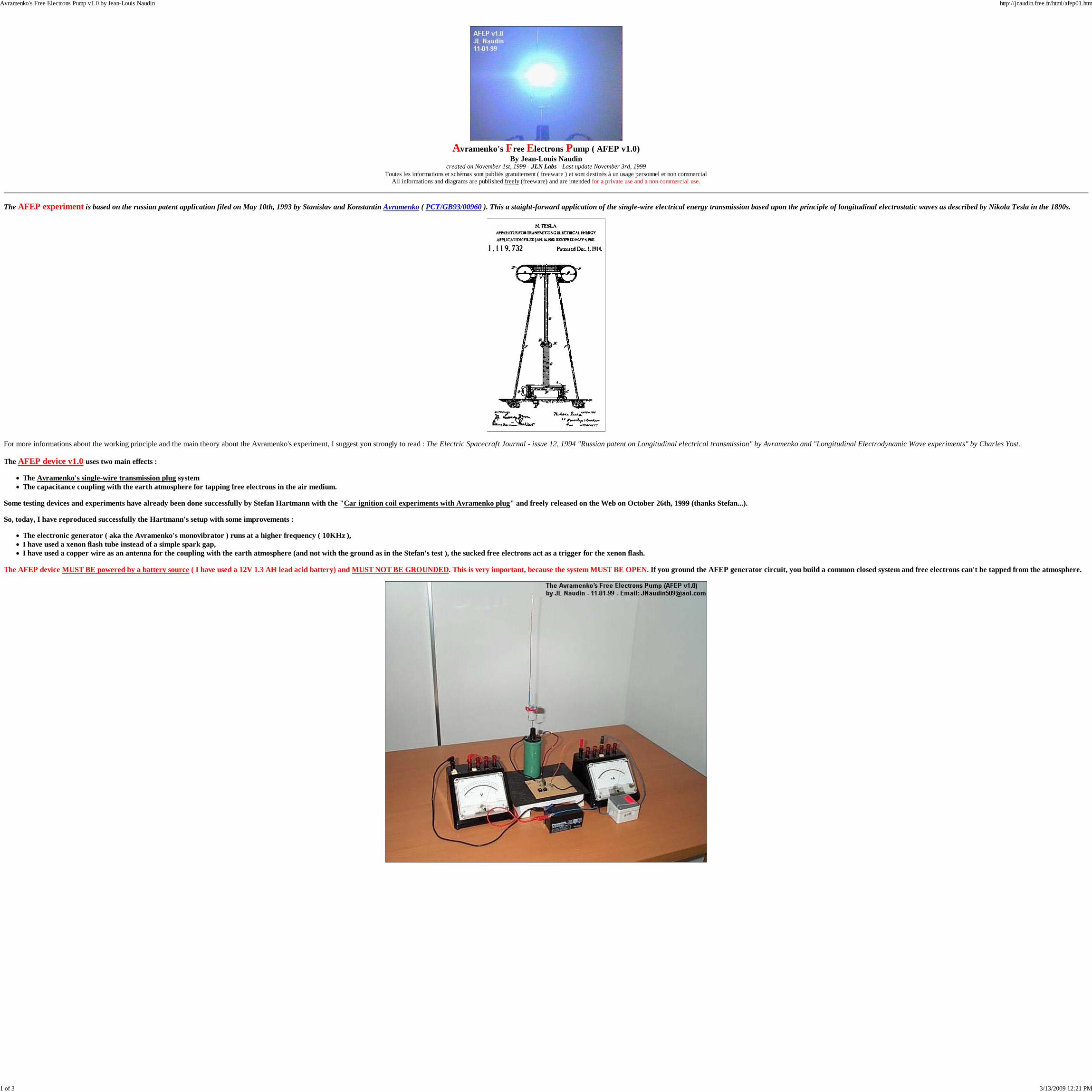
The AFEP experiment is based on the russian patent application filed on May 10th, 1993 by Stanislav and Konstantin Avramenko ( PCT/GB93/00960 ). This a staight-forward application of the single-wire electrical energy transmission based upon the principle of longitudinal electrostatic waves as described by Nikola Tesla in the 1890s.
For more informations about the working principle and the main theory about the Avramenko's experiment, I suggest you strongly to read : The Electric Spacecraft Journal - issue 12, 1994 "Russian patent on Longitudinal electrical transmission" by Avramenko and "Longitudinal Electrodynamic Wave experiments" by Charles Yost.
The AFEP device v1.0 uses two main effects :
The Avramenko's single-wire transmission plug systemThe capacitance coupling with the earth atmosphere for tapping free electrons in the air medium.
Some testing devices and experiments have already been done successfully by Stefan Hartmann with the "Car ignition coil experiments with Avramenko plug" and freely released on the Web on October 26th, 1999 (thanks Stefan...).
So, today, I have reproduced successfully the Hartmann's setup with some improvements :
The electronic generator ( aka the Avramenko's monovibrator ) runs at a higher frequency ( 10KHz ),I have used a xenon flash tube instead of a simple spark gap,I have used a copper wire as an antenna for the coupling with the earth atmosphere (and not with the ground as in the Stefan's test ), the sucked free electrons act as a trigger for the xenon flash.
The AFEP device MUST BE powered by a battery source ( I have used a 12V 1.3 AH lead acid battery) and MUST NOT BE GROUNDED. This is very important, because the system MUST BE OPEN. If you ground the AFEP generator circuit, you build a common closed system and free electrons can't be tapped from the atmosphere.
Avramenko's Free Electrons Pump v1.0 by Jean-Louis Naudin http://jnaudin.free.fr/html/afep01.htm
1 of 3 3/13/2009 12:21 PM
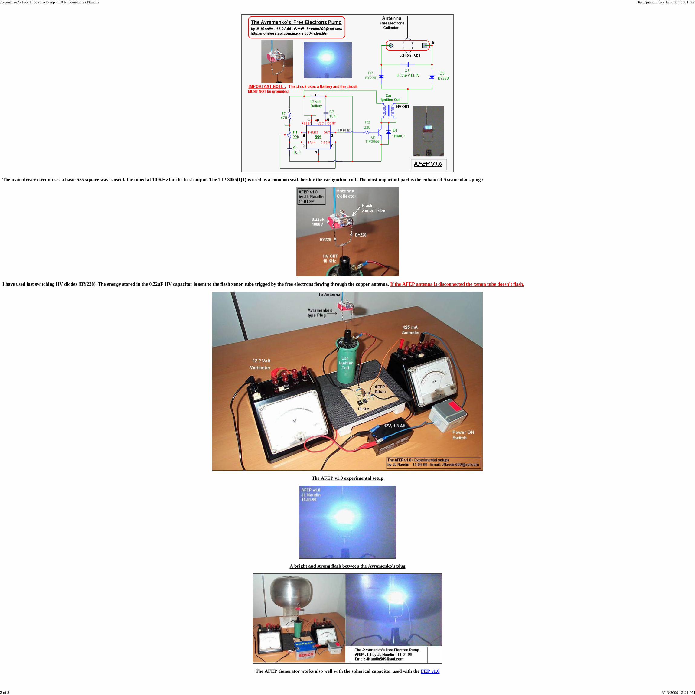
The main driver circuit uses a basic 555 square waves oscillator tuned at 10 KHz for the best output. The TIP 3055(Q1) is used as a common switcher for the car ignition coil. The most important part is the enhanced Avramenko's plug :
I have used fast switching HV diodes (BY228). The energy stored in the 0.22uF HV capacitor is sent to the flash xenon tube trigged by the free electrons flowing through the copper antenna. If the AFEP antenna is disconnected the xenon tube doesn't flash.
The AFEP v1.0 experimental setup
A bright and strong flash between the Avramenko's plug
The AFEP Generator works also well with the spherical capacitor used with the FEP v1.0
Avramenko's Free Electrons Pump v1.0 by Jean-Louis Naudin http://jnaudin.free.fr/html/afep01.htm
2 of 3 3/13/2009 12:21 PM

See also :
The Single-Wire Energy Transmission Test with the AFEP v1.2
The Free Electrons Pump (FEP) v1.0
Reference documents :
- Electric Spacecraft Journal - issue 12, 1994 :"Russian patent on Longitudinal electrical transmission" by Avramenko"Longitudinal Electrodynamic Wave experiments" by Charles Yost- New Energy News - August 1994 : "Solid State Space-Energy Generator" by Stanislav and Konstantin Avramenko.- The Russian patent : (PCT/GB93/00960) - May 10th, 1993 by Stanislav and Konstantin Avramenko.- Tesla US Patent number 1,119,736 : "Apparatus for transmitting electrical energy" (issued Dec. 1, 1914)- Tesla US Patent number 8,200 : " Improvements relating to the transmission of Electrical Energy" (17th Apr.,1906)
Email : [email protected]
Return to Tesla Exploration home page
Avramenko's Free Electrons Pump v1.0 by Jean-Louis Naudin http://jnaudin.free.fr/html/afep01.htm
3 of 3 3/13/2009 12:21 PM

Avramenko's Free Electrons Pump ( AFEP v1.0)By Jean-Louis Naudin
created on November 1st, 1999 - JLN Labs - Last update November 3rd, 1999Toutes les informations et schémas sont publiés gratuitement ( freeware ) et sont destinés à un usage personnel et non commercial
All informations and diagrams are published freely (freeware) and are intended for a private use and a non commercial use.
The AFEP experiment is based on the russian patent application filed on May 10th, 1993 by Stanislav and Konstantin Avramenko ( PCT/GB93/00960 ). This a staight-forward application of the single-wire electrical energy transmission based upon the principle of longitudinal electrostatic waves as described by Nikola Tesla in the 1890s.
For more informations about the working principle and the main theory about the Avramenko's experiment, I suggest you strongly to read : The Electric Spacecraft Journal - issue 12, 1994 "Russian patent on Longitudinal electrical transmission" by Avramenko and "Longitudinal Electrodynamic Wave experiments" by Charles Yost.
The AFEP device v1.0 uses two main effects :
The Avramenko's single-wire transmission plug systemThe capacitance coupling with the earth atmosphere for tapping free electrons in the air medium.
Some testing devices and experiments have already been done successfully by Stefan Hartmann with the "Car ignition coil experiments with Avramenko plug" and freely released on the Web on October 26th, 1999 (thanks Stefan...).
So, today, I have reproduced successfully the Hartmann's setup with some improvements :
The electronic generator ( aka the Avramenko's monovibrator ) runs at a higher frequency ( 10KHz ),I have used a xenon flash tube instead of a simple spark gap,I have used a copper wire as an antenna for the coupling with the earth atmosphere (and not with the ground as in the Stefan's test ), the sucked free electrons act as a trigger for the xenon flash.
The AFEP device MUST BE powered by a battery source ( I have used a 12V 1.3 AH lead acid battery) and MUST NOT BE GROUNDED. This is very important, because the system MUST BE OPEN. If you ground the AFEP generator circuit, you build a common closed system and free electrons can't be tapped from the atmosphere.
Avramenko's Free Electrons Pump v1.0 by Jean-Louis Naudin http://jnaudin.free.fr/html/afep01.htm
1 of 3 3/12/2009 10:05 PM

The main driver circuit uses a basic 555 square waves oscillator tuned at 10 KHz for the best output. The TIP 3055(Q1) is used as a common switcher for the car ignition coil. The most important part is the enhanced Avramenko's plug :
I have used fast switching HV diodes (BY228). The energy stored in the 0.22uF HV capacitor is sent to the flash xenon tube trigged by the free electrons flowing through the copper antenna. If the AFEP antenna is disconnected the xenon tube doesn't flash.
The AFEP v1.0 experimental setup
A bright and strong flash between the Avramenko's plug
The AFEP Generator works also well with the spherical capacitor used with the FEP v1.0
Avramenko's Free Electrons Pump v1.0 by Jean-Louis Naudin http://jnaudin.free.fr/html/afep01.htm
2 of 3 3/12/2009 10:05 PM

See also :
The Single-Wire Energy Transmission Test with the AFEP v1.2
The Free Electrons Pump (FEP) v1.0
Reference documents :
- Electric Spacecraft Journal - issue 12, 1994 :"Russian patent on Longitudinal electrical transmission" by Avramenko"Longitudinal Electrodynamic Wave experiments" by Charles Yost- New Energy News - August 1994 : "Solid State Space-Energy Generator" by Stanislav and Konstantin Avramenko.- The Russian patent : (PCT/GB93/00960) - May 10th, 1993 by Stanislav and Konstantin Avramenko.- Tesla US Patent number 1,119,736 : "Apparatus for transmitting electrical energy" (issued Dec. 1, 1914)- Tesla US Patent number 8,200 : " Improvements relating to the transmission of Electrical Energy" (17th Apr.,1906)
Email : [email protected]
Return to Tesla Exploration home page
Avramenko's Free Electrons Pump v1.0 by Jean-Louis Naudin http://jnaudin.free.fr/html/afep01.htm
3 of 3 3/12/2009 10:05 PM

[NewCandle] Stiffler's DeviceNick Reiter avalonbiker at yahoo.comTue Jan 30 09:14:19 EST 2007
Previous message: [NewCandle] Stiffler's DeviceNext message: [NewCandle] Stiffler's DeviceMessages sorted by: [ date ] [ thread ] [ subject ] [ author ]
Hi all,
Now there's an experimentalist after my own heart!Dude has some neat stuff on his home-site... the watercharging files are fascinating and well worth my read,particularly since I still can't get the damned goofyJoe Cell out of my head. Yay for dude.
I like his use of caveats with his circuit experiments- good sense of caution. I never played with the AvPlug concept at all, with the exception of when Samand I fiddled with micro-inductive scavenge antennacircuits. I always had a bad feeling about anythingthat required a "very special ferrite", though.
That being said, the whole matter DID take me back tosome golden days around 1994 or so, when I fumbledacross a circuit that lit up a 120V mini lamp withvery little apparent power in. It was pretty simple,I had been inputting a sawtooth pulse train at like12V from a generator into a 555 hooked up as a VCO. What I got out was a sequence of pulses where thepulse width decreased with each pulse to a minimum,then a gap, then started over again. I had the outputof the 555going to a meaty little ferrite coredinductor (maybe like 80 mH or something?). When thecircuit was turned on, the whole thing began tooscillate with a neat sine wave at about 20 kHz, and Icould light a little 120V panel lamp with it.
I wrote it up and it had been published by Hal Foxwhen he had the old print version of New Energy News. It was a cagey thing, though, and I relegated it tothe bin of non-reproducible wonders after I failed toget the thing to oscillate and work more than a halfdozen sporadic times or so.
N
--- Jones Beene <jonesb9 at pacbell.net> wrote:
> Keith Nagel wrote:> > Not exactly. What did he tell you it was?> > Didn't you play around with Avramenko's Plug? It's> deceptively simple - > a barium ferrite antenna driven at resonance about> 1.6 MHz in an LC tank > on the primary side and the secondary is "floating"> with some loose > wires - driving a lamp, which may or may not be OU> depending... Over the > weekend on the Vortex forum, an experimenter named> Dr. Ronald Stiffler > who was known to me previously as a competent> experimenter with water > electrolysis and water-fuel posted the following:>
____________________________________________________________________________________Never Miss an EmailStay connected with Yahoo! Mail on your mobile. Get started!http://mobile.yahoo.com/services?promote=mail
Previous message: [NewCandle] Stiffler's DeviceNext message: [NewCandle] Stiffler's DeviceMessages sorted by: [ date ] [ thread ] [ subject ] [ author ]
More information about the NewCandle mailing list
[NewCandle] Stiffler's Device http://pollock.hmdnsgroup.com/pipermail/newcandle_ipdiscover.com/2007-January/000742.html
1 of 1 3/13/2009 12:19 PM

[NewCandle] Stiffler's DeviceJones Beene jonesb9 at pacbell.netMon Jan 29 23:18:27 EST 2007
Previous message: [NewCandle] Stiffler's DeviceNext message: [NewCandle] Stiffler's DeviceMessages sorted by: [ date ] [ thread ] [ subject ] [ author ]
Keith Nagel wrote:> Not exactly. What did he tell you it was?
Didn't you play around with Avramenko's Plug? It's deceptively simple - a barium ferrite antenna driven at resonance about 1.6 MHz in an LC tank on the primary side and the secondary is "floating" with some loose wires - driving a lamp, which may or may not be OU depending... Over the weekend on the Vortex forum, an experimenter named Dr. Ronald Stiffler who was known to me previously as a competent experimenter with water electrolysis and water-fuel posted the following:
> Years ago there was buzz on the news groups about Avramenko's Plug andproposed method of single wire transmission. During the period I did some experiments with the Plug and HV driving Xeons etc., yet found it to be going no where and JLN, Stefan Hartmann and Frolov got involved. JLN did a demo which is still on his site that showed a single wire system driving a Xeon light.
> A couple of months ago something strange showed up in work on a different system which took me back to the Plug. What has evolved is a very nice circuit that 'Cries Foul' because it can not work, but it does and does not have to be floated above ground like the JLN demo was. But the energy output side of the circuit does have to be free of any earth or circuit connection.
> Here are some specs so you all can get a big laugh :-)
> Power input 12VDC at 70mA, now this is close to real as it is determined by a scope integrating at 40MHz. The driver is a MOSFET driven by a 3.5Vpp square wave. The charge capacitor is a 220uf/200V switched into a 120V/7W lamp by a neon bulb relaxation oscillator. Works fine and is stable so long as you connect nothing to the output section (test leads etc) that is why the neon is used as a trigger.
> This is NOT an OU device :-( , it is an energy conversion device. Now where does the excess come from? Well thats a good question because only a certain ferrite core will allow the device to work, even if similar circuit conditions are met with different cores and coils. Yes for those that know, the frequency is critical, but not like one would think, a increase in frequency does not increase power as determined by Frolov.
> I placed a labeled picture at www.stifflerscientific.com/images/avtrig.jpg
> I have brought this to the vorts only as an example of how people could get false excitment :-)
The thread progressed to the Sweet VTA and beyond. I proposed a pretty far out theory (assuming it was OU) based on stimulating the barium isomeric isotope Ba135m, which started to sound better and better, the more I thought about it. More on that later.
Jones
Previous message: [NewCandle] Stiffler's DeviceNext message: [NewCandle] Stiffler's DeviceMessages sorted by: [ date ] [ thread ] [ subject ] [ author ]
More information about the NewCandle mailing list
[NewCandle] Stiffler's Device http://pollock.hmdnsgroup.com/pipermail/newcandle_ipdiscover.com/2007-January/000741.html
1 of 1 3/13/2009 12:17 PM

[NewCandle] Stiffler's DeviceKeith Nagel NewCandleAdmin at ipdiscover.comTue Jan 30 11:07:45 EST 2007
Previous message: [NewCandle] Stiffler's DeviceNext message: [NewCandle] Stiffler's DeviceMessages sorted by: [ date ] [ thread ] [ subject ] [ author ]
What I see from the circuit diagram is an inductive "kicker" toget the 12V up to 120V, and on the secondary side are theappropriate diodes and caps to rectify and store the charge. The neonand semiconductor provide the voltage sensitive switchingfor a relaxation oscillation, which periodically dumps the stored120V into the lamp.
Lamps are rated by voltage, not power. A 120V 7W lamp takes 120Vto light, and 7W continuous power to stay lit. Presumablythis 7W is what got everyone excited, given the input power.But look at the circuit. It stores charge on the secondarycaps until some preset voltage is reached, then fires.
Fact is, Ron points most of the above out himself,and flatly states the device isn't OU. The schematic is also clear.But what does he know, he's just the experimenter (grin).
If he's pushing the core into ferroresonance,then a specific kind of core will work best. I rather suspecthe's not familiar with that phenomena, and it's certainlymysterious to engineers used to working in the linear domain.
Barium ferrite? Why would you think it was that?
K.
-----Original Message-----From: newcandle-bounces at ipdiscover.com[mailto:newcandle-bounces at ipdiscover.com]On Behalf Of Nick ReiterSent: Tuesday, January 30, 2007 9:14 AMTo: New energy for the new world.Subject: Re: [NewCandle] Stiffler's Device
Hi all,
Now there's an experimentalist after my own heart!Dude has some neat stuff on his home-site... the watercharging files are fascinating and well worth my read,particularly since I still can't get the damned goofyJoe Cell out of my head. Yay for dude.
I like his use of caveats with his circuit experiments- good sense of caution. I never played with the AvPlug concept at all, with the exception of when Samand I fiddled with micro-inductive scavenge antennacircuits. I always had a bad feeling about anythingthat required a "very special ferrite", though.
That being said, the whole matter DID take me back tosome golden days around 1994 or so, when I fumbledacross a circuit that lit up a 120V mini lamp withvery little apparent power in. It was pretty simple,I had been inputting a sawtooth pulse train at like12V from a generator into a 555 hooked up as a VCO. What I got out was a sequence of pulses where thepulse width decreased with each pulse to a minimum,then a gap, then started over again. I had the outputof the 555going to a meaty little ferrite coredinductor (maybe like 80 mH or something?). When thecircuit was turned on, the whole thing began tooscillate with a neat sine wave at about 20 kHz, and Icould light a little 120V panel lamp with it.
I wrote it up and it had been published by Hal Foxwhen he had the old print version of New Energy News. It was a cagey thing, though, and I relegated it tothe bin of non-reproducible wonders after I failed toget the thing to oscillate and work more than a halfdozen sporadic times or so.
N
--- Jones Beene <jonesb9 at pacbell.net> wrote:
> Keith Nagel wrote:> > Not exactly. What did he tell you it was?> > Didn't you play around with Avramenko's Plug? It's> deceptively simple - > a barium ferrite antenna driven at resonance about> 1.6 MHz in an LC tank > on the primary side and the secondary is "floating"> with some loose > wires - driving a lamp, which may or may not be OU> depending... Over the > weekend on the Vortex forum, an experimenter named> Dr. Ronald Stiffler > who was known to me previously as a competent> experimenter with water > electrolysis and water-fuel posted the following:>
____________________________________________________________________________________Never Miss an EmailStay connected with Yahoo! Mail on your mobile. Get started!http://mobile.yahoo.com/services?promote=mail
_______________________________________________NewCandle mailing listNewCandle at ipdiscover.comhttp://ipdiscover.com/mailman/listinfo/newcandle_ipdiscover.com
Previous message: [NewCandle] Stiffler's DeviceNext message: [NewCandle] Stiffler's DeviceMessages sorted by: [ date ] [ thread ] [ subject ] [ author ]
More information about the NewCandle mailing list
[NewCandle] Stiffler's Device http://pollock.hmdnsgroup.com/pipermail/newcandle_ipdiscover.com/2007-January/000743.html
1 of 1 3/13/2009 12:19 PM

[NewCandle] Stiffler's DeviceJones Beene jonesb9 at pacbell.netTue Jan 30 13:31:43 EST 2007
Previous message: [NewCandle] Stiffler's DeviceNext message: [NewCandle] Stiffler's DeviceMessages sorted by: [ date ] [ thread ] [ subject ] [ author ]
Keith, Nick et al.,
Barium ferrite? Why would you think it was that?
Well - it was just a guess - which he later confirmed.
In private mail, he was pretty "shocked" that I could guess it so quickly, but I had been focusing recently on revivals of the Sweet VTA, on another forum - which - BION- with new information, there is a good argument for that device really being OU "at times".... (properly "conditioned" core)
Turns out, with the Stiffler circuit what he doesn't say is as importatn as what he does... and when any other comparably-wound ferrite core is used, the bulb will not even begin to lite up. This does not suggest real OU of course, but the following message sent to Fred today pretty much expresses my sentiment about the so-called radiant (wattless) energy.
Frederick Sparber wrote:
> If it wasn't for the cost I would use at least three VDGs for getting> a multipole field configuration to see how it interacts with the > earth-ionosphere charges.
Fred, there is a most interesting convergence of ideas going-on here that might push your experiment "higher" so-to-speak, in anti-gravity terms.
I am referring to the three-way collection of postings over the weekend regarding "Energy Violations" and "Circuit cries Foul" and VDG/AG etc. Did you catch that there is this glaring overlap, once you tun into the details, in those threads with what you are doing?
Ultimately, I am suggesting the possibility of adding an Avramenko's Plug 'type' of Free Electron Pump to operate in tandem with a VDG:
http://jnaudin.free.fr/html/afep01.htm
The might allow the two operate with synergism, to wit:
Any motion of charge is electric current by definition, even if the motion is relatively minor compared to the potential. The electric potential field can move charge; especially in an AC or pulsed DC situation and this results in "free" work or energy, but of a strange sort, which I think that this is where the possible overlap between all of these recent threads on Vortex lies. It is (probably) enough to use the electrical field (scalar potential source) to create the power and work in an electric load circuit, which is then recycled back, with some added electrons drawn in from ambient. This could be autocatalytic.
But bordering on this is the semantic quandary: which Frolov/Bearden state something to the effect that there are both the "wattful" current and "wattless" current. Almost brings a smiley out, doesn't it. To create the so-called "free energy system," then, it is necessary to transform the wattless current to wattful current - but that might be only possible in an "in situ" situation, resulting in antigravity as the end product. Almost brings a bigger smiley out, doesn't it.
This kind of lingo: OU-speak - will turn many EEs (not Terry) to mush but nevertheless, this is the same kind of thing one hears regarding "cold electricity" and "Radiant energy" in other circles. The point being that there is a "special kind" of EMF available in nature, which is not exactly watt-denominated (so to speak). It is not exactly electrostatic either. This is the crux of the Tesla controversy.
I urge you to look into this possibility as an altenative (and cheaper way) instead of adding another VDG. Especially note that Naudin's version of the plug with an automotive ignition coil, or a lighter weight version, might operate kind of as an intermediary system, even though I suspect that the barium ferrite antennas of Dr. Stiffler are adding something special also, in the way of usable EMF. IOW you would not need to add more power, just kind of a "reverse VDG" - if you catch my drift.
But the bottom line is that so long as your gram-scale can accomodate the added weight, you might be able to combine many of these hypothetical ideas - although to be honest - the best approach to doing this is not clear.
Make sure that there is no one on you roof at the time you fire it up <g>.
Jones
Previous message: [NewCandle] Stiffler's DeviceNext message: [NewCandle] Stiffler's DeviceMessages sorted by: [ date ] [ thread ] [ subject ] [ author ]
More information about the NewCandle mailing list
[NewCandle] Stiffler's Device http://pollock.hmdnsgroup.com/pipermail/newcandle_ipdiscover.com/2007-January/000744.html
1 of 1 3/13/2009 12:20 PM

[NewCandle] Stiffler's DeviceKeith Nagel NewCandleAdmin at ipdiscover.comTue Jan 30 14:42:32 EST 2007
Previous message: [NewCandle] Stiffler's DeviceNext message: [NewCandle] Stiffler's DeviceMessages sorted by: [ date ] [ thread ] [ subject ] [ author ]
You know, there's this guy, Tom Beardon...but you do know.
I don't think Ron really knows what the core is made of.I'd guess that he has a bunch of surplus cores that he'splaying with, and some are manganese zinc, others nickel zinc.That would explain why at high frequency he's only lighting the bulbwith the fast core material. It also sounded to me likehe was driving the core into ferroresonance, as hedecribed nonlinear tuning phenomena in his posts.
So what's the new information about Sparky Sweets device?
K.
-----Original Message-----From: newcandle-bounces at ipdiscover.com[mailto:newcandle-bounces at ipdiscover.com]On Behalf Of Jones BeeneSent: Tuesday, January 30, 2007 1:32 PMTo: New energy for the new world.Subject: Re: [NewCandle] Stiffler's Device
Keith, Nick et al.,
Barium ferrite? Why would you think it was that?
Well - it was just a guess - which he later confirmed.
In private mail, he was pretty "shocked" that I could guess it so quickly, but I had been focusing recently on revivals of theSweet VTA, on another forum - which - BION- with new information, there is a good argument for that device really being OU "attimes".... (properly "conditioned" core)
Turns out, with the Stiffler circuit what he doesn't say is as importatn as what he does... and when any other comparably-woundferrite core is used, the bulb will not even begin to lite up. This does not suggest real OU of course, but the following messagesent to Fred today pretty much expresses my sentiment about the so-called radiant (wattless) energy.
Frederick Sparber wrote:
> If it wasn't for the cost I would use at least three VDGs for getting> a multipole field configuration to see how it interacts with the> earth-ionosphere charges.
Fred, there is a most interesting convergence of ideas going-on herethat might push your experiment "higher" so-to-speak, in anti-gravity terms.
I am referring to the three-way collection of postings over the weekendregarding "Energy Violations" and "Circuit cries Foul" and VDG/AG etc.Did you catch that there is this glaring overlap, once you tun into thedetails, in those threads with what you are doing?
Ultimately, I am suggesting the possibility of adding an Avramenko'sPlug 'type' of Free Electron Pump to operate in tandem with a VDG:
http://jnaudin.free.fr/html/afep01.htm
The might allow the two operate with synergism, to wit:
Any motion of charge is electric current by definition, even if themotion is relatively minor compared to the potential. The electricpotential field can move charge; especially in an AC or pulsed DCsituation and this results in "free" work or energy, but of a strangesort, which I think that this is where the possible overlap between allof these recent threads on Vortex lies. It is (probably) enough to usethe electrical field (scalar potential source) to create the power andwork in an electric load circuit, which is then recycled back, with someadded electrons drawn in from ambient. This could be autocatalytic.
But bordering on this is the semantic quandary: which Frolov/Beardenstate something to the effect that there are both the "wattful" currentand "wattless" current. Almost brings a smiley out, doesn't it. Tocreate the so-called "free energy system," then, it is necessary totransform the wattless current to wattful current - but that might beonly possible in an "in situ" situation, resulting in antigravity as theend product. Almost brings a bigger smiley out, doesn't it.
This kind of lingo: OU-speak - will turn many EEs (not Terry) to mushbut nevertheless, this is the same kind of thing one hears regarding"cold electricity" and "Radiant energy" in other circles. The pointbeing that there is a "special kind" of EMF available in nature, whichis not exactly watt-denominated (so to speak). It is not exactlyelectrostatic either. This is the crux of the Tesla controversy.
I urge you to look into this possibility as an altenative (and cheaperway) instead of adding another VDG. Especially note that Naudin'sversion of the plug with an automotive ignition coil, or a lighterweight version, might operate kind of as an intermediary system, eventhough I suspect that the barium ferrite antennas of Dr. Stiffler areadding something special also, in the way of usable EMF. IOW you wouldnot need to add more power, just kind of a "reverse VDG" - if you catchmy drift.
But the bottom line is that so long as your gram-scale can accomodatethe added weight, you might be able to combine many of thesehypothetical ideas - although to be honest - the best approach to doingthis is not clear.
Make sure that there is no one on you roof at the time you fire it up <g>.
Jones
_______________________________________________NewCandle mailing listNewCandle at ipdiscover.comhttp://ipdiscover.com/mailman/listinfo/newcandle_ipdiscover.com
Previous message: [NewCandle] Stiffler's DeviceNext message: [NewCandle] Stiffler's DeviceMessages sorted by: [ date ] [ thread ] [ subject ] [ author ]
More information about the NewCandle mailing list
[NewCandle] Stiffler's Device http://pollock.hmdnsgroup.com/pipermail/newcandle_ipdiscover.com/2007-January/000745.html
1 of 1 3/13/2009 12:22 PM

[NewCandle] Stiffler's DeviceJones Beene jonesb9 at pacbell.netTue Jan 30 15:43:09 EST 2007
Previous message: [NewCandle] Stiffler's DeviceNext message: [NewCandle] Stiffler's DeviceMessages sorted by: [ date ] [ thread ] [ subject ] [ author ]
Keith,
Hey, I know, I know ... in the past I have been more skeptical and publicly so (which is a rarity for moi) than almost anyone about Bearden & Co. I think his greatest fault was in trying to shoehorn everything into his standard spiel - but OTOH that because of his circumstance as being the first spokesperson for "free energy" and his historical placemany in the field - that he was a magnet for some of the anomalous underlying experiments (done by others) which could have shown
Here is an edited piece cut-and-pasted from a Tesla site. It demonstrates some of the semantic problems.
I don't have an answer as to what is going on, but as of now, I am convinced that there is "something" about barium in HV situations. What though ?? .... that is the $64 question
To attempt to understand "negative energy" two variations of normal scientific terms are used.
Hot Current: This is the normal form of EMF.
Cold current: This might be a "time reversed" counterpart of normal hot current.
Discussion of cold current:
A device that time reverses an electromagnetic wave can be called 'phase conjugate mirror,' but I'm not sure that helps. The concept is not new but it could be one key to 'free energy.' The mistake made by the academic establishment was to assume a constant increase in entropy is the inevitable result of all physical interactions in every time frame. This is only true so long as time flows forward. Time may stop "flowing" under certain circumstances - such as spatial dimensions below the Forster radius.
Is Entropy simply a process governed by local macroscopic time flow ? Maybe.
OK so far I can buy into this. It meshes in well with the Dirac notion of "reciprocal space" so long as we assume that this mathematical construct: reciprocal space is normal 3-space with time reversed. But how do you "reverse time" ? And can it be reversed in little segments interspersed along with the normal arrow of time, so that you seem to have no time distortion at the macro level?
Here is an historical (hysterical <g>) attempt to answer this going back to the original "Mr T" hissef:
Executive summary (of a sort) -- shockwave = temporary time reversal
By 1890, after a period of intense experimentation and design development, Tesla summarized the components necessary for the practical deployment of a radiant electrical power distribution system. Tesla had already discovered the wonderful fact that impulse durations of 100 microseconds or less could not be sensed and would do no physiological harm. He planned to use these in his power broadcast. Furthermore, shocking waves of 100 microsecond duration passed through all matter, a fitting form of electrical energy to broadcast throughout the stone, steel, and glass of a power-needy city. Tesla would not expect distortions with specially adjusted energy fields, vectors which permeated matter without interactive effects.
Tesla made a most startling discovery the same year, when placing a long single-turn copper helix near his magnetic disrupter. The coil, some two feet in length, did not behave as did solid copper pipes and other objects. The thin walled coil became ensheathed in an envelope of white sparks. Undulating from the crown of this coil were very long and fluidic silvery white streamers, soft discharges which appeared to have been considerably raised in voltage. These effects were greatly intensified when the helical coil was placed within the disrupter wire circle. Inside this "shockzone", the helical coil was surrounded in a blast which hugged into its surface, and rode up the coil to its open end. It seemed as though the shockwave actually pulled away from surrounding space to cling to the coil surface, a strange attractive preference. The shockwave flowed over the coil at right angles to the windings, an unbelievable effect. The sheer length of discharges leaping from the helix crown was incomprehensible. With the disrupter discharge jumping I inch in its magnetic housing, the white shimmering discharges rose from the helix to a measured length of over two feet. This discharge equaled the very length of the coil itself'. It was an unexpected and unheard transformation.
Here was an action more nearly "electrostatic" in nature, although he knew that academes would not comprehend this term when used in this situation. Electrostatic energy did not fluctuate as did his shockwaves. The explosive shockwave had characteristics unlike any other electrical machine in existence. Yet Tesla stated that the shockwave, during the brief instant in which it made its explosive appearance, more nearly resembled an electrostatic field than any other known electrical manifestation. just as in electrostatic friction machines, where current and magnetism are negligible, a very energetic field component fills space in radiating lines. This 'dielectric" field normally launches through space in a slow growth as charges are gathered. Here was a case where a DC generator provided the high voltage. This voltage charged an insulated hoop of copper, growing to its maximum value. If all values in the circuit were properly balanced, in the manner prescribed by Tesla, a sudden charge collapse would then occur. This collapse was necessarily very much shorter than the interval required to charge the hoop. The collapse comes when the magnetic disrupter extinguishes the arc. If the circuit is properly structured, no backrush alternations ever occur.
This unidirectional succession of charge-discharge impulses causes a very strange field to expand outward, one which vaguely resembles a "Stuttering' or 'staccato" electrostatic field. But these terms did not satisfactorily describe the conditions actually measured around the apparatus, a powerful radiant effect exceeding all expectable electrostatic values. Actual calculation of these discharge ratios proved impossible. Implementing the standard magneto-inductive transformer rule, Tesla was unable to account for the enormous voltage multiplication effect. Conventional relationships failing, Tesla hypothesized that the effect was due entirely to radiant transformation rules, obviously requiring empirical determination. Subsequent measurements of discharge lengths and helix attributes provided the necessary new mathematical relationship.
He had discovered a new induction law, one where radiant shockwaves actually auto-intensified when encountering segmented objects. The segmentation was the key to releasing the action. Radiant shockwaves encountered an helix and "flashed over" the outer skin, from end to end. This shockwave did not pass through the windings of the coil at all, treating the coil surface as an aerodynamic plane. The shockwave pulse auto-intensified exactly as gas pressures continually increase when passing through Venturi tubes. A consistent increase in electrical pressure was measured along the coil surface. Indeed, Tesla stated that voltages could often be increased at an amazing 10,000 volts per inch of axial coil surface. This meant that a 24 inch coil could absorb radiant shockwaves which initially measured 10,000 volts, with a subsequent maximum rise to 240,000 volts! Such transformations of voltage were unheard with apparatus of this volume and simplicity. Tesla further discovered that the output voltages were mathematically related to the resistance of turns in the helix. Higher resistance meant higher voltage maxima.
He began referring to his disrupter line as his special "primary", and to the helical coil placed within the shockzone, as his special "secondary". But he never intended anyone to equate these terms with those referring to magnetoelectric transformers. This discovery was indeed completely different from magneto-induction. There was a real and measurable reason why he could make this outlandish statement. There was an attribute which completely baffled Tesla for a time. Tesla measured a zero current condition in these long copper secondary coils. He determined that the current which should have appeared was completely absent. Pure voltage was rising with each inch of coil surface. Tesla constantly referred to his "electrostatic induction laws", a principle which few comprehended. Tesla called the combined disrupter and secondary helix a 'Transformer".
Tesla Transformers are not magnetoelectric devices, they use radiant shockwaves, and produce pure voltage without current. No university High Frequency Coil must ever be called a "Tesla Coil", since the devices usually employed in demonstration halls are the direct result of apparatus perfected by Sir Oliver Lodge and not by Nikola Tesla. The Tesla Transformer is an impulse apparatus, and cannot be as easily constructed except by strict conformity with parameters which Tesla enunciated. Tesla Transformers produce extraordinary white impulse discharges of extreme length and pressure, which exceed the alternating violet spark displays of Lodge Coils. This is illustrated by noting the manner in which Tesla Transformers are actually constructed. While looking and seeming the same, each system actually performs very different functions. Lodge Coils are alternators. Tesla Transformers are unidirectional impulses. The most efficient Tesla Transformations were obtained only when the disruptive radiating wire line equaled the mass of the helical coil.
More later (or shall I dispense with MrT ?)
Previous message: [NewCandle] Stiffler's DeviceNext message: [NewCandle] Stiffler's DeviceMessages sorted by: [ date ] [ thread ] [ subject ] [ author ]
More information about the NewCandle mailing list
[NewCandle] Stiffler's Device http://pollock.hmdnsgroup.com/pipermail/newcandle_ipdiscover.com/2007-January/000746.html
1 of 1 3/13/2009 12:23 PM

[NewCandle] Stiffler's DeviceNick Reiter avalonbiker at yahoo.comWed Jan 31 10:49:27 EST 2007
Previous message: [NewCandle] Stiffler's DeviceMessages sorted by: [ date ] [ thread ] [ subject ] [ author ]
Hi Jones,
Well, here you get to the crux of where my thoughtshave been turning for the past year or two. Lookingat the thermodynamics of the apparati.
In just about every case where something unusual SEEMSto have worked - from cold fusion cells (apologies tothe CF traditionalists out there) to Sparky Sweet tubethingies to magnetic mystery machines - there appearto me to be two common principles, regardless of thesystem schematic...
1. The local arrow of entropy is being bent orreversed in a surprising way. Living non-reversiblesystems can do this, ergo the temptation for some toinvoke a sort of "Vitalism" into the machine, viaorgone, Joe Cell-ish esoteric conditioning with"living water", etc.
2. The unusual effects are intermittent, and theoccasions when "it" works drop off in what to me (fromfirsthand experience as well) seems like an oftenexponentially decremental way. Like the experimenteris using up "lucky-ons" too quickly.
So what are Luckyons? My chief (although not only)guess is that these devious little critters are indeedsome sort of time reversed particle that somehow cannest inside "normal" electrodynamic or thermodynamicprocesses. During the time when I was focused on theHudson claims of strange matter - white gold powder, Iwondered if this material - if it ever really existed- could have been something like a gold atom wheresome proportion of the atomic neutrons were actuallytime reversed anti-neutrons. Probably a nuttythought. Still, for my brainhurt factor its alwayshelped me to envision the thermodynamic flukes thatallow OU devices or Joe Cells or even CF reactors towork once in a while as being particulate in some way,and capable of exchanging and propagating.
Bob forbid it should be so simple... build a machine -who cares what it looks like - that won't work innormal entropic space-time, though if things wouldbend JUST A LITTLE BIT the other way, it would reallytake off. Then figure out how to invite localLuckyons into the system, and coax them to stay awhile. I could get obnoxiously metaphysical beyondthat point, so I'd best drop it fer now:)
> OK so far I can buy into this. It meshes in well> with the Dirac notion of "reciprocal space" so long> as we assume that this mathematical construct:> reciprocal space is normal 3-space with time> reversed. But how do you "reverse time" ? And can it> be reversed in little segments interspersed along> with the normal arrow of time, so that you seem to> have no time distortion at the macro level?>
____________________________________________________________________________________Expecting? Get great news right away with email Auto-Check. Try the Yahoo! Mail Beta.http://advision.webevents.yahoo.com/mailbeta/newmail_tools.html
Previous message: [NewCandle] Stiffler's DeviceMessages sorted by: [ date ] [ thread ] [ subject ] [ author ]
More information about the NewCandle mailing list
[NewCandle] Stiffler's Device http://pollock.hmdnsgroup.com/pipermail/newcandle_ipdiscover.com/2007-January/000747.html
1 of 1 3/13/2009 12:24 PM
The Free Electrons Pump ( FEP v1.0)By Stefan Hartmann and Jean-Louis Naudin
created on October 28th, 1999 - JLN Labs - Last update November 6th, 1999Toutes les informations et schémas sont publiés gratuitement ( freeware ) et sont destinés à un usage personnel et non commercial
All informations and diagrams are published freely (freeware) and are intended for a private use and a non commercial use.
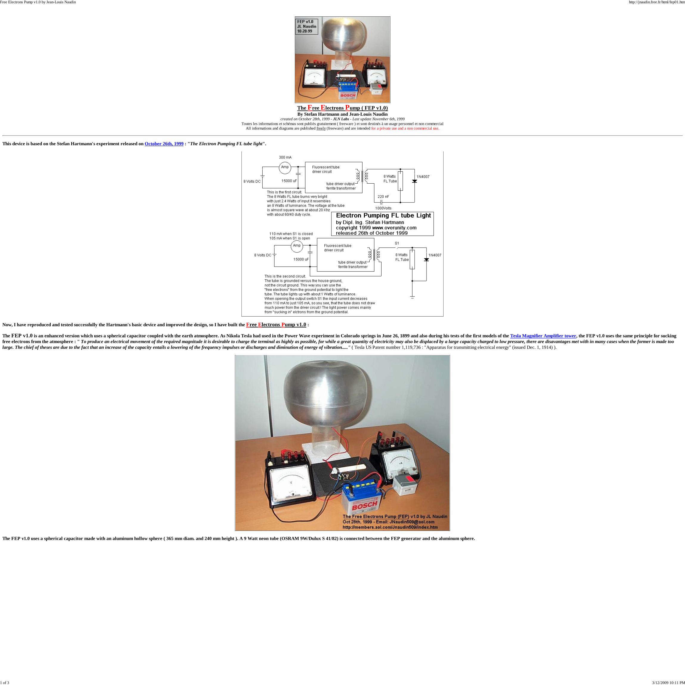
This device is based on the Stefan Hartmann's experiment released on October 26th, 1999 : "The Electron Pumping FL tube light".
Now, I have reproduced and tested successfully the Hartmann's basic device and improved the design, so I have built the Free Electrons Pump v1.0 :
The FEP v1.0 is an enhanced version which uses a spherical capacitor coupled with the earth atmosphere. As Nikola Tesla had used in the Power Wave experiment in Colorado springs in June 26, 1899 and also during his tests of the first models of the Tesla Magnifier Amplifier tower, the FEP v1.0 uses the same principle for suckingfree electrons from the atmosphere : " To produce an electrical movement of the required magnitude it is desirable to charge the terminal as highly as possible, for while a great quantity of electricity may also be displaced by a large capacity charged to low pressure, there are disavantages met with in many cases when the former is made toolarge. The chief of theses are due to the fact that an increase of the capacity entails a lowering of the frequency impulses or discharges and diminution of energy of vibration....." ( Tesla US Patent number 1,119,736 : "Apparatus for transmitting electrical energy" (issued Dec. 1, 1914) ).
The FEP v1.0 uses a spherical capacitor made with an aluminum hollow sphere ( 365 mm diam. and 240 mm height ). A 9 Watt neon tube (OSRAM 9W/Dulux S 41/82) is connected between the FEP generator and the aluminum sphere.
Free Electrons Pump v1.0 by Jean-Louis Naudin http://jnaudin.free.fr/html/fep01.htm
1 of 3 3/12/2009 10:11 PM
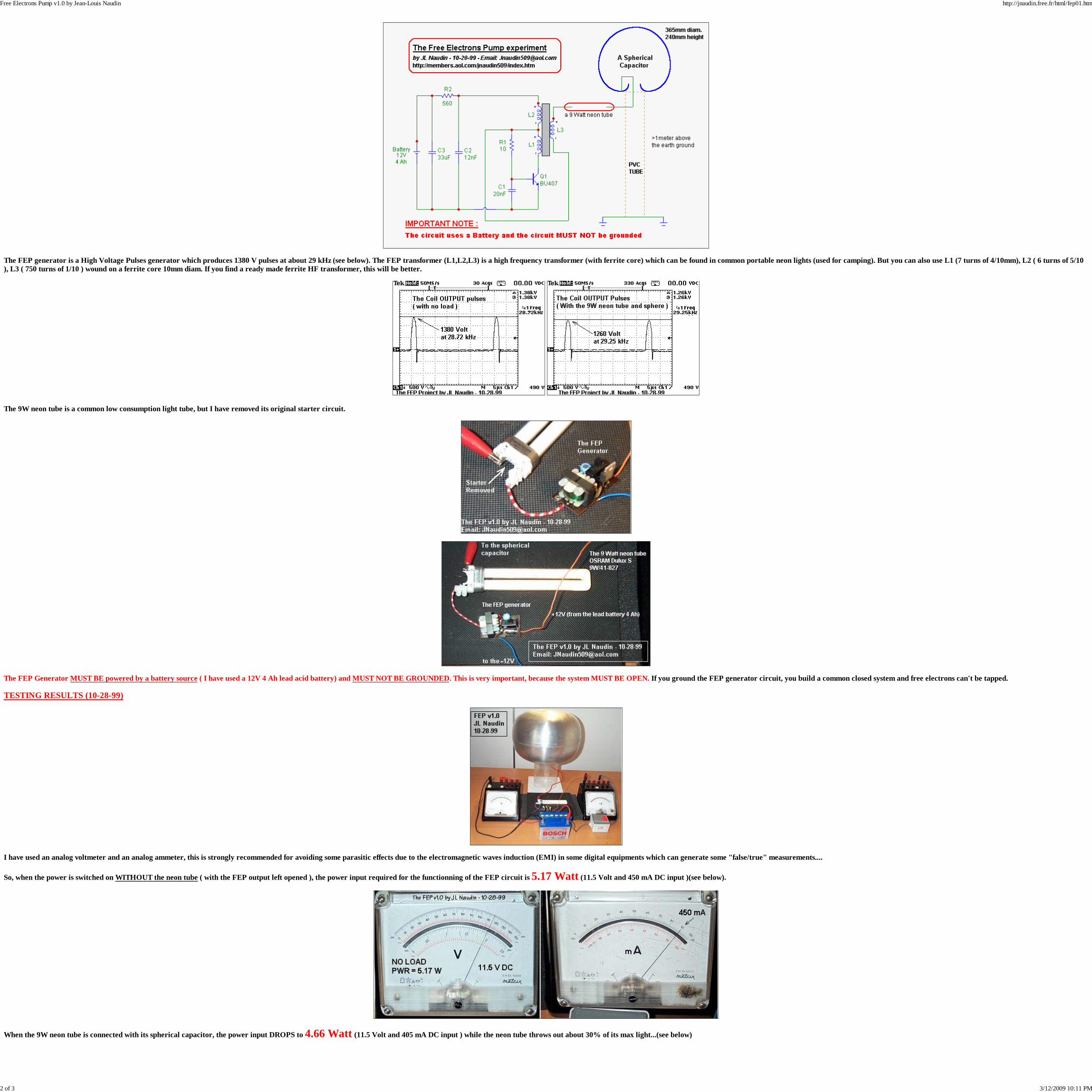
The FEP generator is a High Voltage Pulses generator which produces 1380 V pulses at about 29 kHz (see below). The FEP transformer (L1,L2,L3) is a high frequency transformer (with ferrite core) which can be found in common portable neon lights (used for camping). But you can also use L1 (7 turns of 4/10mm), L2 ( 6 turns of 5/10), L3 ( 750 turns of 1/10 ) wound on a ferrite core 10mm diam. If you find a ready made ferrite HF transformer, this will be better.
The 9W neon tube is a common low consumption light tube, but I have removed its original starter circuit.
The FEP Generator MUST BE powered by a battery source ( I have used a 12V 4 Ah lead acid battery) and MUST NOT BE GROUNDED. This is very important, because the system MUST BE OPEN. If you ground the FEP generator circuit, you build a common closed system and free electrons can't be tapped.
TESTING RESULTS (10-28-99)
I have used an analog voltmeter and an analog ammeter, this is strongly recommended for avoiding some parasitic effects due to the electromagnetic waves induction (EMI) in some digital equipments which can generate some "false/true" measurements....
So, when the power is switched on WITHOUT the neon tube ( with the FEP output left opened ), the power input required for the functionning of the FEP circuit is 5.17 Watt (11.5 Volt and 450 mA DC input )(see below).
When the 9W neon tube is connected with its spherical capacitor, the power input DROPS to 4.66 Watt (11.5 Volt and 405 mA DC input ) while the neon tube throws out about 30% of its max light...(see below)
Free Electrons Pump v1.0 by Jean-Louis Naudin http://jnaudin.free.fr/html/fep01.htm
2 of 3 3/12/2009 10:11 PM
Note : If you don't have an aluminum spherical capacitor, you may also use a big aluminum sheet as a free electrons collector.
Now that you have a very simple electronic circuit that you can build and test by yourself, you will notice that this circuit works very well and shows that some free electrons can be tapped easily, from the atmosphere or from the ground with the FEP v1.0 device...
Jean-Louis Naudin October 28th, 1999
POWER I/O Measurements ( JLN 10-29-99) :
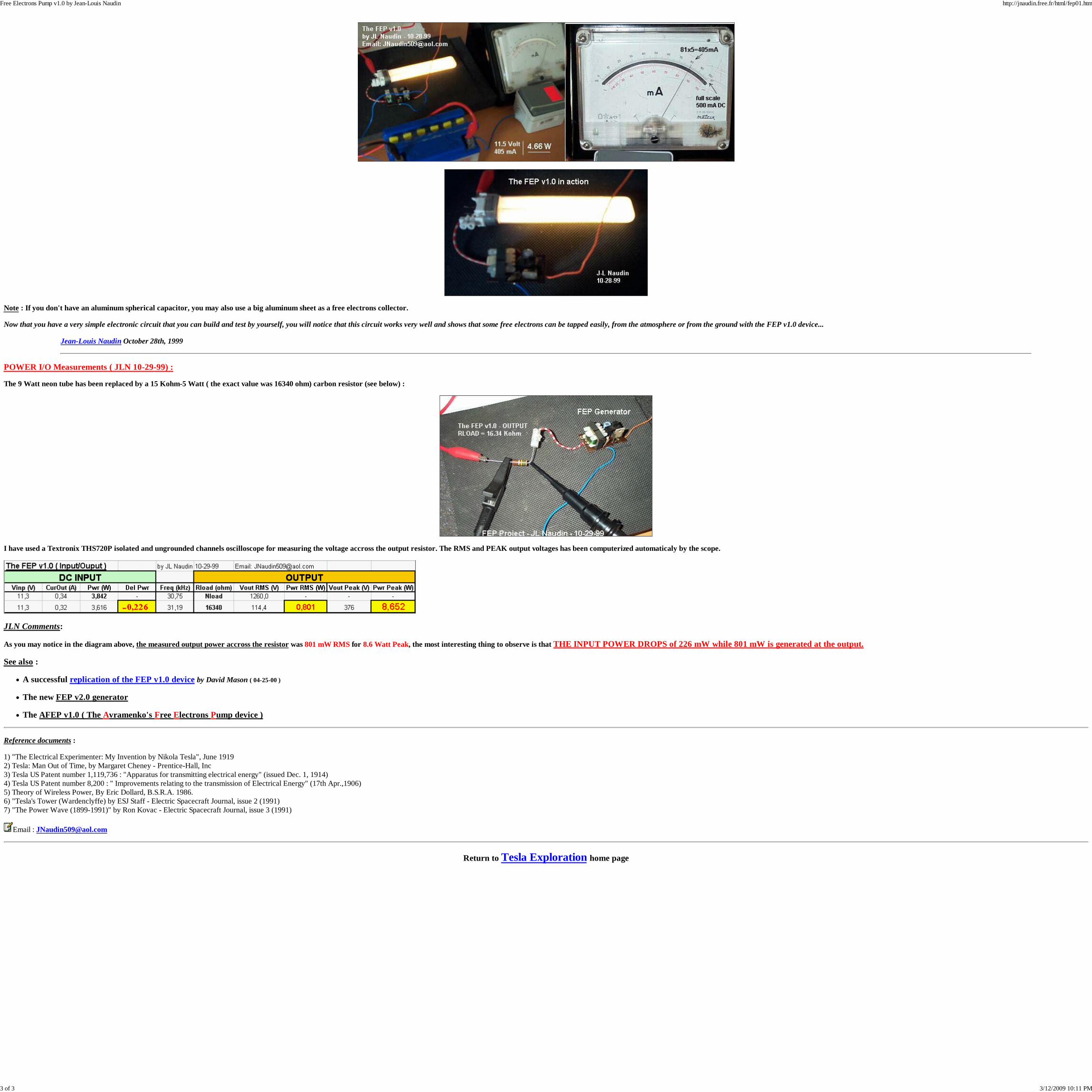
The 9 Watt neon tube has been replaced by a 15 Kohm-5 Watt ( the exact value was 16340 ohm) carbon resistor (see below) :
I have used a Textronix THS720P isolated and ungrounded channels oscilloscope for measuring the voltage accross the output resistor. The RMS and PEAK output voltages has been computerized automaticaly by the scope.
JLN Comments:
As you may notice in the diagram above, the measured output power accross the resistor was 801 mW RMS for 8.6 Watt Peak, the most interesting thing to observe is that THE INPUT POWER DROPS of 226 mW while 801 mW is generated at the output.
See also :
A successful replication of the FEP v1.0 device by David Mason ( 04-25-00 )
The new FEP v2.0 generator
The AFEP v1.0 ( The Avramenko's Free Electrons Pump device )
Reference documents :
1) "The Electrical Experimenter: My Invention by Nikola Tesla", June 19192) Tesla: Man Out of Time, by Margaret Cheney - Prentice-Hall, Inc3) Tesla US Patent number 1,119,736 : "Apparatus for transmitting electrical energy" (issued Dec. 1, 1914)4) Tesla US Patent number 8,200 : " Improvements relating to the transmission of Electrical Energy" (17th Apr.,1906)5) Theory of Wireless Power, By Eric Dollard, B.S.R.A. 1986.6) "Tesla's Tower (Wardenclyffe) by ESJ Staff - Electric Spacecraft Journal, issue 2 (1991)7) "The Power Wave (1899-1991)" by Ron Kovac - Electric Spacecraft Journal, issue 3 (1991)
Email : [email protected]
Return to Tesla Exploration home page
Free Electrons Pump v1.0 by Jean-Louis Naudin http://jnaudin.free.fr/html/fep01.htm
3 of 3 3/12/2009 10:11 PM
THE TIME ENERGY PUMPCreated 20/04/00 - Last Update 29/04/00
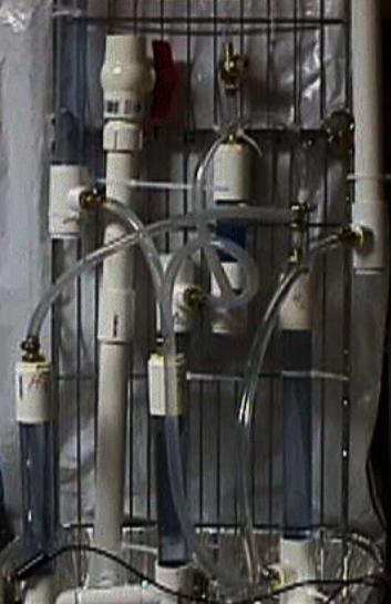
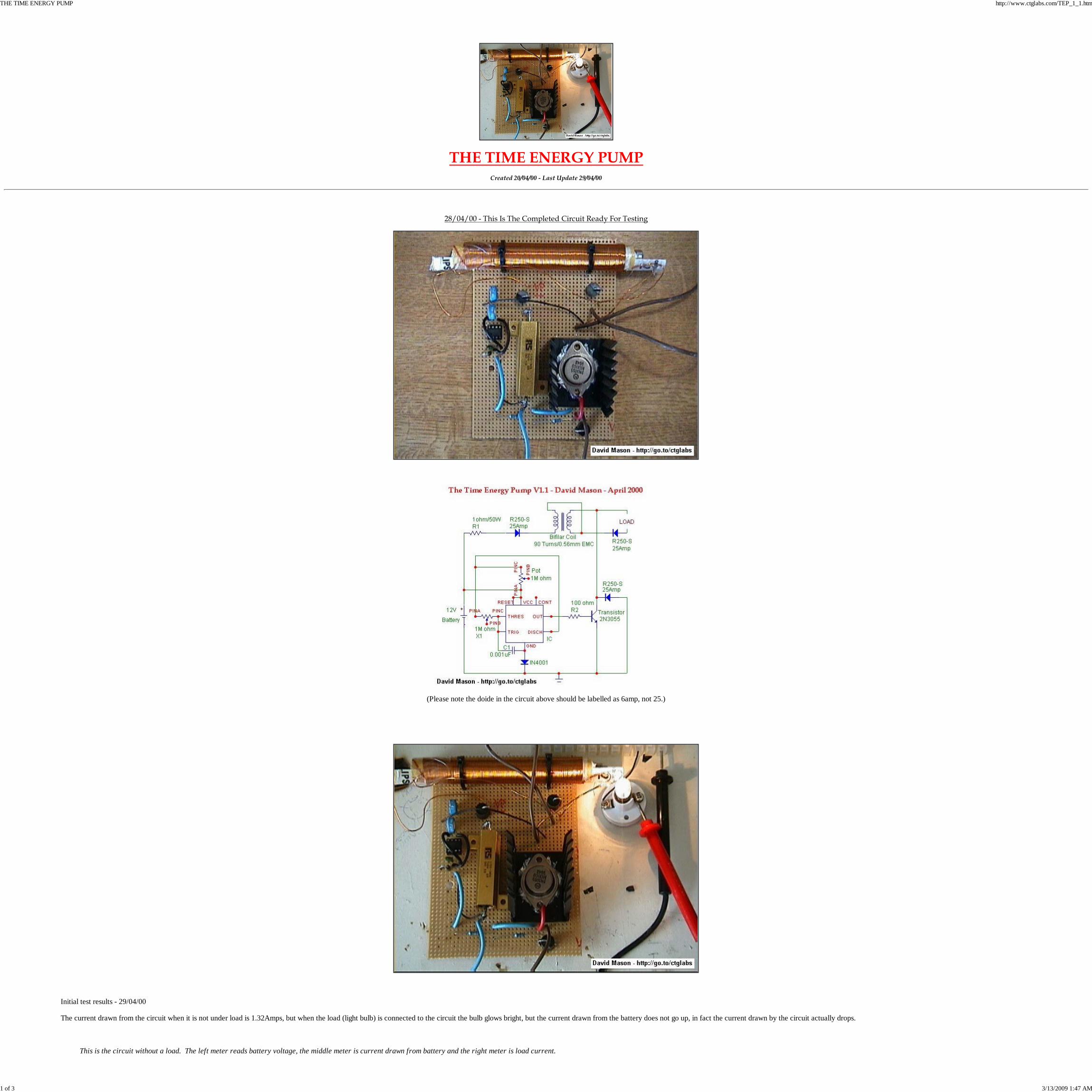
28/04/00 - This Is The Completed Circuit Ready For Testing
(Please note the doide in the circuit above should be labelled as 6amp, not 25.)
Initial test results - 29/04/00
The current drawn from the circuit when it is not under load is 1.32Amps, but when the load (light bulb) is connected to the circuit the bulb glows bright, but the current drawn from the battery does not go up, in fact the current drawn by the circuit actually drops.
This is the circuit without a load. The left meter reads battery voltage, the middle meter is current drawn from battery and the right meter is load current.
THE TIME ENERGY PUMP http://www.ctglabs.com/TEP_1_1.htm
1 of 3 3/13/2009 1:47 AM
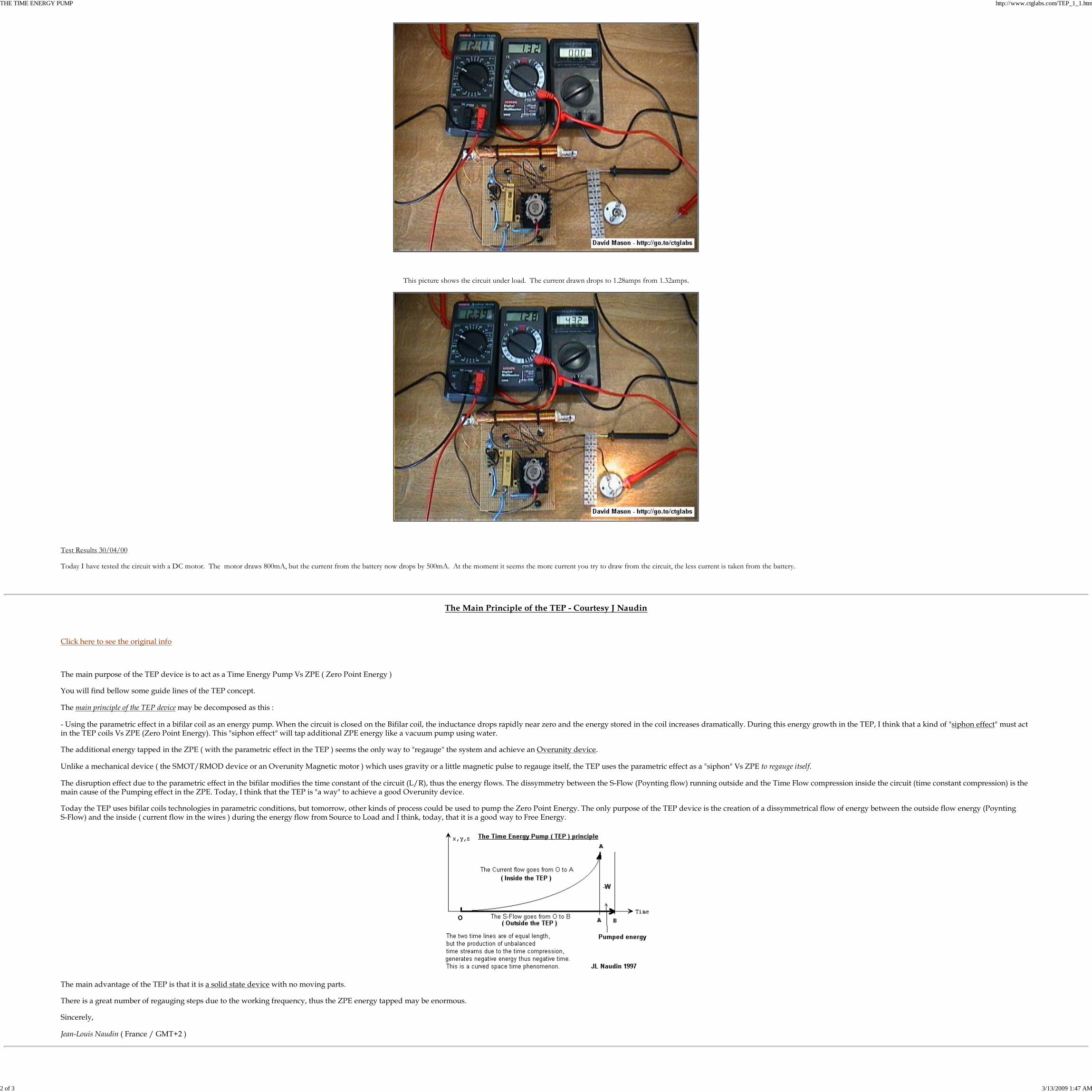
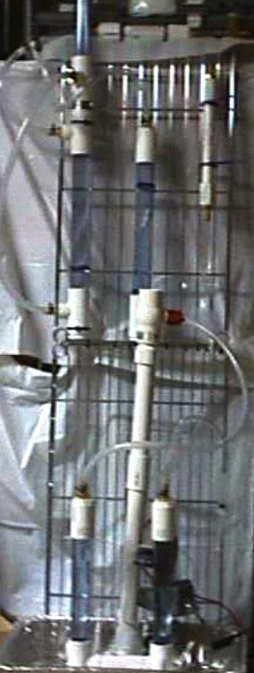
This picture shows the circuit under load. The current drawn drops to 1.28amps from 1.32amps.
Test Results 30/04/00
Today I have tested the circuit with a DC motor. The motor draws 800mA, but the current from the battery now drops by 500mA. At the moment it seems the more current you try to draw from the circuit, the less current is taken from the battery.
The Main Principle of the TEP - Courtesy J Naudin
Click here to see the original info
The main purpose of the TEP device is to act as a Time Energy Pump Vs ZPE ( Zero Point Energy )
You will find bellow some guide lines of the TEP concept.
The main principle of the TEP device may be decomposed as this :
- Using the parametric effect in a bifilar coil as an energy pump. When the circuit is closed on the Bifilar coil, the inductance drops rapidly near zero and the energy stored in the coil increases dramatically. During this energy growth in the TEP, I think that a kind of "siphon effect" must actin the TEP coils Vs ZPE (Zero Point Energy). This "siphon effect" will tap additional ZPE energy like a vacuum pump using water.
The additional energy tapped in the ZPE ( with the parametric effect in the TEP ) seems the only way to "regauge" the system and achieve an Overunity device.
Unlike a mechanical device ( the SMOT/RMOD device or an Overunity Magnetic motor ) which uses gravity or a little magnetic pulse to regauge itself, the TEP uses the parametric effect as a "siphon" Vs ZPE to regauge itself.
The disruption effect due to the parametric effect in the bifilar modifies the time constant of the circuit (L/R), thus the energy flows. The dissymmetry between the S-Flow (Poynting flow) running outside and the Time Flow compression inside the circuit (time constant compression) is themain cause of the Pumping effect in the ZPE. Today, I think that the TEP is "a way" to achieve a good Overunity device.
Today the TEP uses bifilar coils technologies in parametric conditions, but tomorrow, other kinds of process could be used to pump the Zero Point Energy. The only purpose of the TEP device is the creation of a dissymmetrical flow of energy between the outside flow energy (PoyntingS-Flow) and the inside ( current flow in the wires ) during the energy flow from Source to Load and I think, today, that it is a good way to Free Energy.
The main advantage of the TEP is that it is a solid state device with no moving parts.
There is a great number of regauging steps due to the working frequency, thus the ZPE energy tapped may be enormous.
Sincerely,
Jean-Louis Naudin ( France / GMT+2 )
THE TIME ENERGY PUMP http://www.ctglabs.com/TEP_1_1.htm
2 of 3 3/13/2009 1:47 AM

Home
THE TIME ENERGY PUMP http://www.ctglabs.com/TEP_1_1.htm
3 of 3 3/13/2009 1:47 AM

THE TIME ENERGY PUMP PROJECT
Link to J Naudins/S Hartmans Work
Test Model V.1.1 - Successful Test ?
TEP V.1.2 - Good Results?
TEP V.1.3 - Testing The Smith/Caduceus Coil
Home
THE TIME ENERGY PUMP PROJECT http://www.ctglabs.com/time_energy_pump_project.htm
1 of 1 3/13/2009 1:45 AM
.
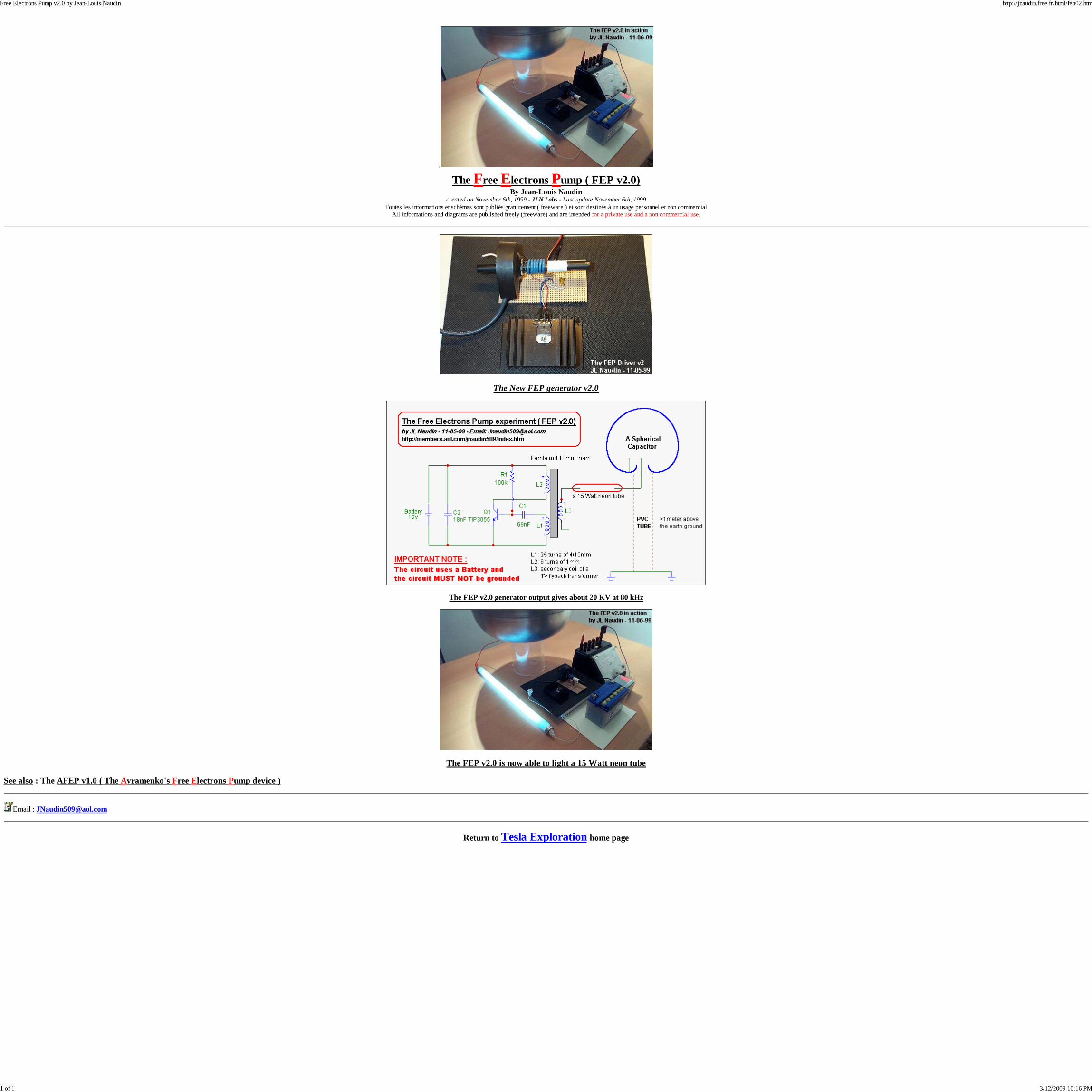
The Free Electrons Pump ( FEP v2.0)By Jean-Louis Naudin
created on November 6th, 1999 - JLN Labs - Last update November 6th, 1999Toutes les informations et schémas sont publiés gratuitement ( freeware ) et sont destinés à un usage personnel et non commercial
All informations and diagrams are published freely (freeware) and are intended for a private use and a non commercial use.
The New FEP generator v2.0
The FEP v2.0 generator output gives about 20 KV at 80 kHz
The FEP v2.0 is now able to light a 15 Watt neon tube
See also : The AFEP v1.0 ( The Avramenko's Free Electrons Pump device )
Email : [email protected]
Return to Tesla Exploration home page
Free Electrons Pump v2.0 by Jean-Louis Naudin http://jnaudin.free.fr/html/fep02.htm
1 of 1 3/12/2009 10:16 PM

Alternative Energy ResearchSpatial Energy Coherence
Dr. Ronald StifflerStiffler Scientific & Technologies
Copyright (c) 2007-2008 Dr. Ronald Stiffler. All rights reserved.Unauthorized Copying of this material is strictly forbidden.
Violation of these Copyrights will be enforced.
***Current G2 Documentation Manual***
Generation II SEC Exciters
One of the first G2 Exciters built on a SEC15-3 PCB. The SEC15-3 was designed to allow for upgrading to a SEC14-G2, although a new PCB was designed specifically for the SEC14-G2, which includes the additional functionality of an electrolysis cell driver.
Alone came the SEC14-1G1 with the capability of doubling, tripling and quadrupling the recovered Spatial Energy. A method was developed much different from conventional doublers and triplers that required a minimal addition to a Basic SEC15-3.
SEC14-1G1 Prototype
The exciter on the left is a modified SEC15-3 with parasitic plate and the prototype on the right is a three stage SEC14-1G1. The difference between the two neon's intensities tells the whole story.
Copyright 2006-2008 Dr. Ronald Stiffler. All rights reserved.Revised: 07/01/2008
http://67.76.235.52/G2Exciters.asp
1 of 1 3/13/2009 10:42 AM
Avramenko's Free Electrons Pump projectTest Reports and Updates
By Jean-Louis Naudincreated on November 5th,, 1999 - JLN Labs - Last update November5th, 1999
Toutes les informations et schémas sont publiés gratuitement ( freeware ) et sont destinés à un usage personnel et non commercialAll informations and diagrams are published freely (freeware) and are intended for a private use and a non commercial use.
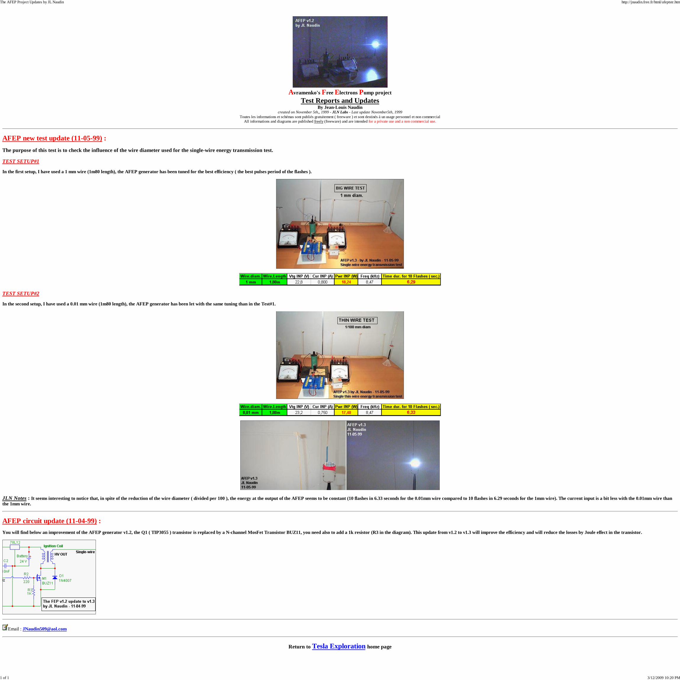
AFEP new test update (11-05-99) :The purpose of this test is to check the influence of the wire diameter used for the single-wire energy transmission test.
TEST SETUP#1
In the first setup, I have used a 1 mm wire (1m80 length), the AFEP generator has been tuned for the best efficiency ( the best pulses period of the flashes ).
TEST SETUP#2
In the second setup, I have used a 0.01 mm wire (1m80 length), the AFEP generator has been let with the same tuning than in the Test#1.
JLN Notes : It seems interesting to notice that, in spite of the reduction of the wire diameter ( divided per 100 ), the energy at the output of the AFEP seems to be constant (10 flashes in 6.33 seconds for the 0.01mm wire compared to 10 flashes in 6.29 seconds for the 1mm wire). The current input is a bit less with the 0.01mm wire thanthe 1mm wire.
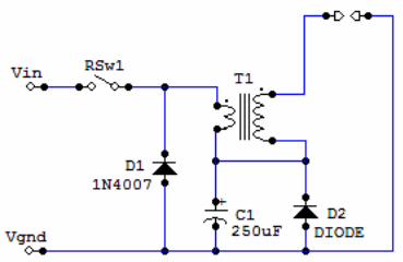
AFEP circuit update (11-04-99) :You will find below an improvement of the AFEP generator v1.2, the Q1 ( TIP3055 ) transistor is replaced by a N-channel MosFet Transistor BUZ11, you need also to add a 1k resistor (R3 in the diagram). This update from v1.2 to v1.3 will improve the efficiency and will reduce the losses by Joule effect in the transistor.
Email : [email protected]
Return to Tesla Exploration home page
The AFEP Project Updates by JL Naudin http://jnaudin.free.fr/html/afeptstr.htm
1 of 1 3/12/2009 10:20 PM
Avramenko's Free Electrons Pump ( AFEP v1.2)Single-Wire Energy Transmission test
By Jean-Louis Naudincreated on November 3rd,, 1999 - JLN Labs - Last update November 5th, 1999
Toutes les informations et schémas sont publiés gratuitement ( freeware ) et sont destinés à un usage personnel et non commercialAll informations and diagrams are published freely (freeware) and are intended for a private use and a non commercial use.
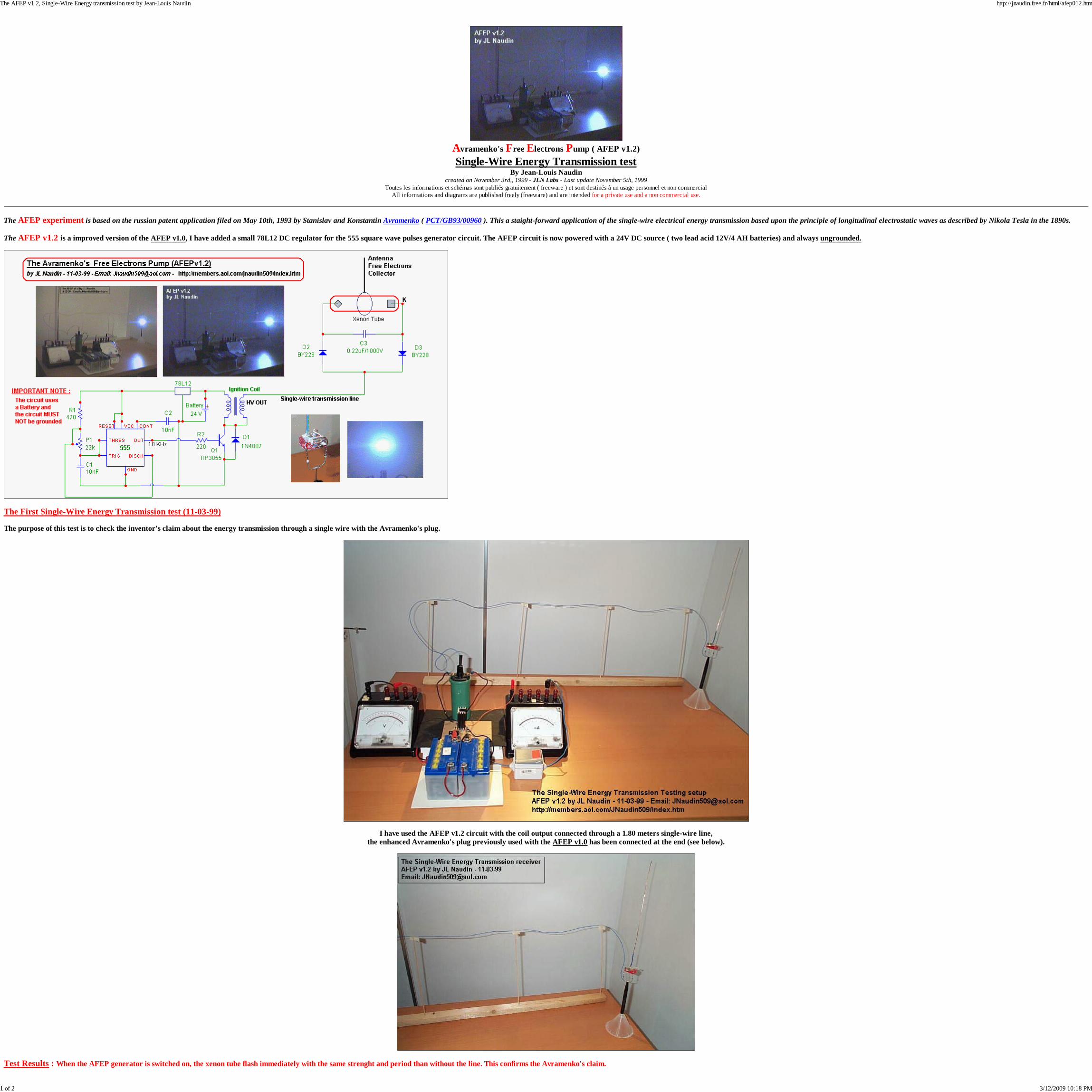
The AFEP experiment is based on the russian patent application filed on May 10th, 1993 by Stanislav and Konstantin Avramenko ( PCT/GB93/00960 ). This a staight-forward application of the single-wire electrical energy transmission based upon the principle of longitudinal electrostatic waves as described by Nikola Tesla in the 1890s.
The AFEP v1.2 is a improved version of the AFEP v1.0, I have added a small 78L12 DC regulator for the 555 square wave pulses generator circuit. The AFEP circuit is now powered with a 24V DC source ( two lead acid 12V/4 AH batteries) and always ungrounded.
The First Single-Wire Energy Transmission test (11-03-99)
The purpose of this test is to check the inventor's claim about the energy transmission through a single wire with the Avramenko's plug.
I have used the AFEP v1.2 circuit with the coil output connected through a 1.80 meters single-wire line,the enhanced Avramenko's plug previously used with the AFEP v1.0 has been connected at the end (see below).
Test Results : When the AFEP generator is switched on, the xenon tube flash immediately with the same strenght and period than without the line. This confirms the Avramenko's claim.
The AFEP v1.2, Single-Wire Energy transmission test by Jean-Louis Naudin http://jnaudin.free.fr/html/afep012.htm
1 of 2 3/12/2009 10:18 PM
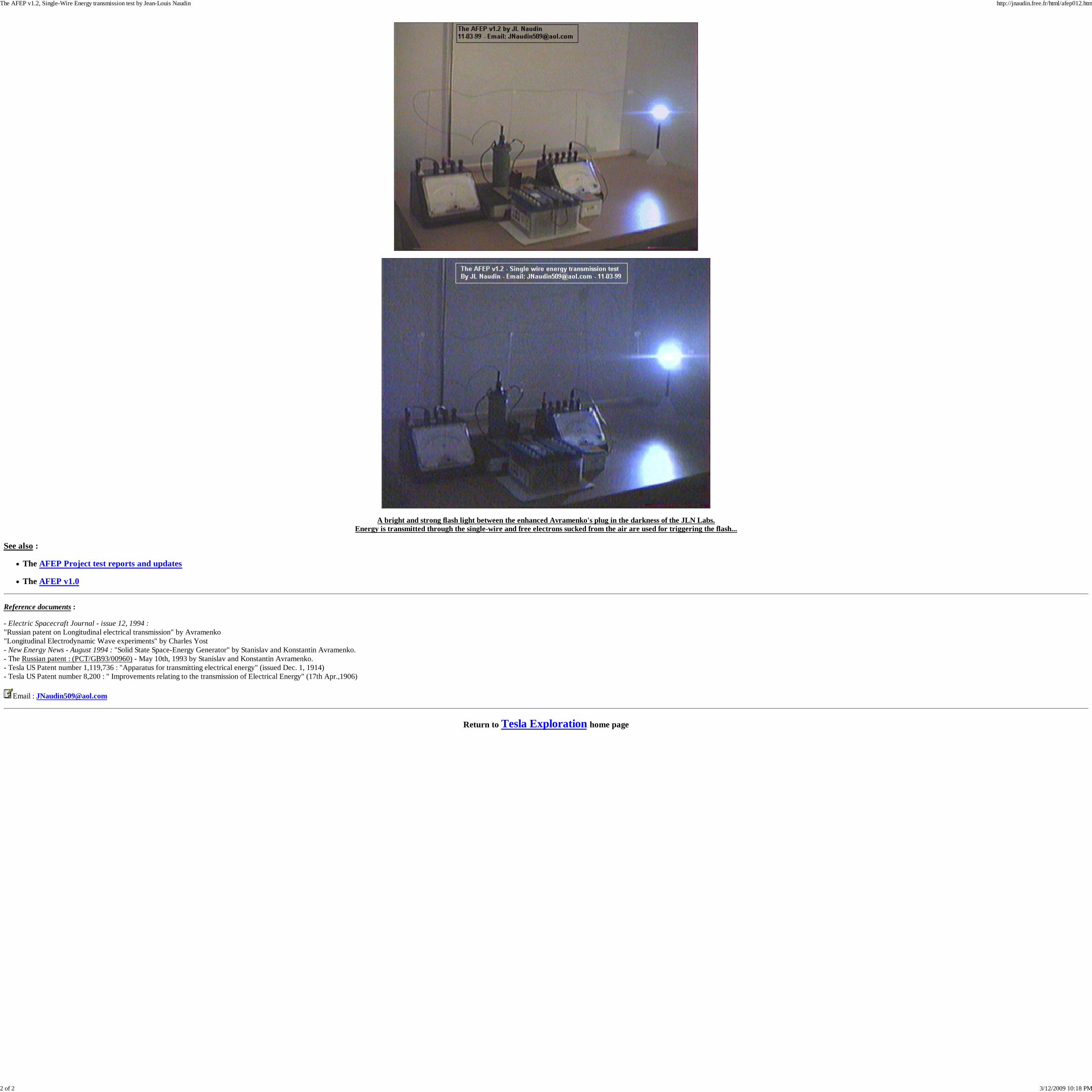
A bright and strong flash light between the enhanced Avramenko's plug in the darkness of the JLN Labs.Energy is transmitted through the single-wire and free electrons sucked from the air are used for triggering the flash...
See also :
The AFEP Project test reports and updates
The AFEP v1.0
Reference documents :
- Electric Spacecraft Journal - issue 12, 1994 :"Russian patent on Longitudinal electrical transmission" by Avramenko"Longitudinal Electrodynamic Wave experiments" by Charles Yost- New Energy News - August 1994 : "Solid State Space-Energy Generator" by Stanislav and Konstantin Avramenko.- The Russian patent : (PCT/GB93/00960) - May 10th, 1993 by Stanislav and Konstantin Avramenko.- Tesla US Patent number 1,119,736 : "Apparatus for transmitting electrical energy" (issued Dec. 1, 1914)- Tesla US Patent number 8,200 : " Improvements relating to the transmission of Electrical Energy" (17th Apr.,1906)
Email : [email protected]
Return to Tesla Exploration home page
The AFEP v1.2, Single-Wire Energy transmission test by Jean-Louis Naudin http://jnaudin.free.fr/html/afep012.htm
2 of 2 3/12/2009 10:18 PM

Order Only: 440-205-8388 Request for photos
Product by Keywords
•
• Advanced Search
Other Info
• Company Policies
Current: FERRITE
Slug-Tuned coil forms
Manufacturer: COILCRAFT Other ProductsSales Price
$.25 Mfg. Part # 161007-14Condition FNUnitIn Stock 4700In Stock And Ready To Ship!
If you have any question, please contact our sales representative for assistance.
Product Overview
Slug-Tuned coil forms. Stands 7/8" Off PC board 1/4" diameter with 3/16" diameter adjustable powdered iron core. Sale 4/$1.00 1K/$100.00
7-092, RD0676 Last Cat 26-15
©1999-2002 Electronic Surplus Inc. All Rights Reserved contact webmaster | powered by corezonAll logos and trademarks are properties of their respective companies. Product price, specification, warranty and availability subject to change without notice.
161007-14-Slug-Tuned coil forms-Electronic Surplus Inc.Offering obsolete IC's, discretes, motors, relays, switches, pots, and much, much more! Always looking for your excess inventory. http://www.electronicsurplus.com/ccp70021-slug-tuned-coil-forms--161007-14-3862.htm
1 of 3 3/13/2009 10:47 AM

Shop by Brand
Shop by Product Category • AIR CONDITIONER • ANTENNAS • ATTENUATORS • AUDIO • AV EQUIPMENT • BATTERY ACCESSORIES • BOARDS • BOOKS • CABLE • CABLE ASSEMBLIES • CAPACITORS • CIRCUIT BREAKERS • COMPUTER PRODUCTS • CONNECTORS • CONTACTORS • CONTAINERS & BOTTLES • CORDS • COUNTERS • COVER PLATES • CRYSTALS • CYLINDERS • DC/DC CONVERTER • DELAY LINE • DICTAPHONE • DIODES • DISPLAYS • ENCLOSURES • ENCODERS • EPROM ERASER • EXOTIC • FANS • FERRITE • FILTERS • FITTINGS/ VALVES • FUSES • GOULD REPLACEMENT
PARTS • HALL EFFECT • HARDWARE • HEAT SINKS • HEATERS • HEATING ELEMENT • HI VOLT • IC • IGBT • INDUCTORS • INVERTER • KEYBOARDS • LABORATORY • LAMPS • LASER • LED • LENS & MIRRORS • LIBRARY BOOKS • MAGNETRONS • MAGNETS • Manuals • MEDICAL • MEDICAL/ X-RAY • METERS & GAUGES • MICROWAVE • MILITARY • MISC • MOTORS • MOV • MYSTERY • OPTICAL EQUIPMENT • OPTO • OPTO DISPLAY • OSCILLOSCOPE • OVERCURRENT PROTECTOR • PHOTOELECTRIC • PHOTOGRAPHIC • PHOTORESISTOR • PICKER • POTENTIOMETERS • POWER SUPPLIES • PROBES • PROCESS CONTROL • PROJECT BOARD • PROXIMITY SENSORS • PUMPS • REFERENCE MANUALS • RELAYS • RESISTORS • RF • RHEOSTATS • SCR • SECURITY • SEMICONDUCTORS • SENSORS • SIERRA SCIENTIFIC • SOCKETS • SOLDER EQUIPMENT • SOLDERLESS TERMINALS • SOLENOIDS • SPEAKERS • SURGE SUPPRESSORS • SWITCHES • Switches / Thermostatic -
SEE THERMOSTATS . . . • TELECOM • TELECONFERENCING • TELEPHONE • TERMINAL STRIPS • TEST CLIPS • TEST EQUIPMENT • THERMISTOR • THERMOSTAT • TIMERS • TOOLS • TOROIDS • TRANSDUCERS • TRANSFORMERS
161007-14-Slug-Tuned coil forms-Electronic Surplus Inc.Offering obsolete IC's, discretes, motors, relays, switches, pots, and much, much more! Always looking for your excess inventory. http://www.electronicsurplus.com/ccp70021-slug-tuned-coil-forms--161007-14-3862.htm
2 of 3 3/13/2009 10:47 AM

• TRANSISTORS • TRIAC • TRIMPOTS • TUBES • TVP • VALVES • VELLEMAN • VIDEO • VOLTAGE REGULATOR • WHOLESALE LOTS • WIRE / CABLE • WIRE LOOM
Purchase Assistance
• Your Order Status
• Your Quotation
• Your Account
• Your Company Account
161007-14-Slug-Tuned coil forms-Electronic Surplus Inc.Offering obsolete IC's, discretes, motors, relays, switches, pots, and much, much more! Always looking for your excess inventory. http://www.electronicsurplus.com/ccp70021-slug-tuned-coil-forms--161007-14-3862.htm
3 of 3 3/13/2009 10:47 AM

Alternative Energy ResearchUtilizing
Charge Recycle ElectrolyzerCRE
Dr. Ronald StifflerStiffler Scientific & Technologies
Last Update: 04/01/2008
Charge Recycle Electrolyzer - CRE http://67.76.235.52/cre.asp
1 of 4 3/13/2009 10:30 AM
DO NOT attempt replication of my research, unless you are fully aware of the dangers involved in workingwith Hydrogen gas. You must insure that the Hydrogen and Oxygen are not allowed to mix. Mixtures of H2and O2 are reactive in concentrations from ~4% > 74%. All apparatus should be vaccum tested and evacuatedof Oxygen before Hydrogen production is commenced. Stiffler Scientific is not responsible for, or holds anylibility for damage or injury to person or property resulting from the duplication of our work.
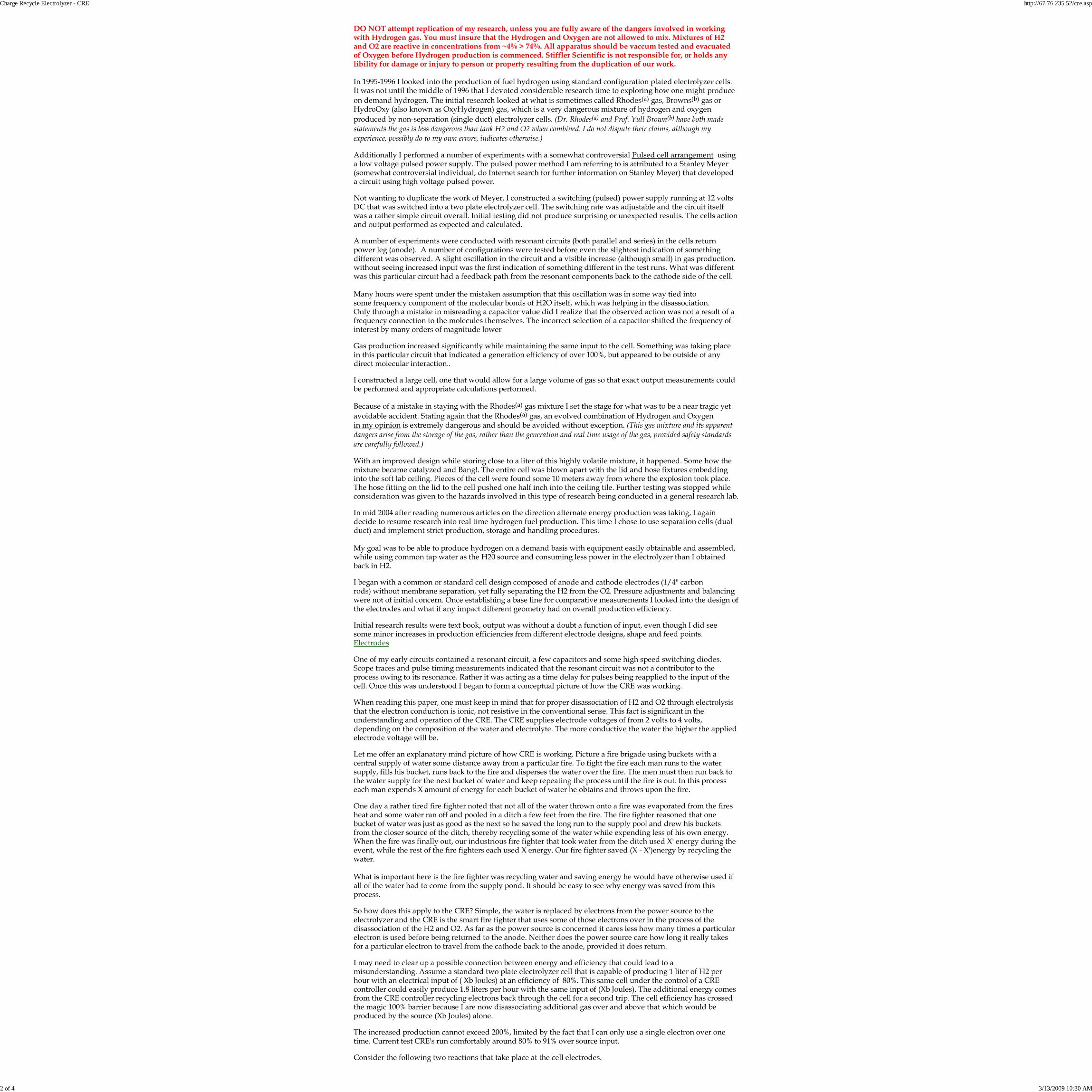
In 1995-1996 I looked into the production of fuel hydrogen using standard configuration plated electrolyzer cells.It was not until the middle of 1996 that I devoted considerable research time to exploring how one might produceon demand hydrogen. The initial research looked at what is sometimes called Rhodes(a) gas, Browns(b) gas orHydroOxy (also known as OxyHydrogen) gas, which is a very dangerous mixture of hydrogen and oxygenproduced by non-separation (single duct) electrolyzer cells. (Dr. Rhodes(a) and Prof. Yull Brown(b) have both madestatements the gas is less dangerous than tank H2 and O2 when combined. I do not dispute their claims, although myexperience, possibly do to my own errors, indicates otherwise.)
Additionally I performed a number of experiments with a somewhat controversial Pulsed cell arrangement usinga low voltage pulsed power supply. The pulsed power method I am referring to is attributed to a Stanley Meyer(somewhat controversial individual, do Internet search for further information on Stanley Meyer) that developeda circuit using high voltage pulsed power.
Not wanting to duplicate the work of Meyer, I constructed a switching (pulsed) power supply running at 12 voltsDC that was switched into a two plate electrolyzer cell. The switching rate was adjustable and the circuit itselfwas a rather simple circuit overall. Initial testing did not produce surprising or unexpected results. The cells actionand output performed as expected and calculated.
A number of experiments were conducted with resonant circuits (both parallel and series) in the cells returnpower leg (anode). A number of configurations were tested before even the slightest indication of somethingdifferent was observed. A slight oscillation in the circuit and a visible increase (although small) in gas production,without seeing increased input was the first indication of something different in the test runs. What was differentwas this particular circuit had a feedback path from the resonant components back to the cathode side of the cell.
Many hours were spent under the mistaken assumption that this oscillation was in some way tied intosome frequency component of the molecular bonds of H2O itself, which was helping in the disassociation.Only through a mistake in misreading a capacitor value did I realize that the observed action was not a result of afrequency connection to the molecules themselves. The incorrect selection of a capacitor shifted the frequency ofinterest by many orders of magnitude lower
Gas production increased significantly while maintaining the same input to the cell. Something was taking placein this particular circuit that indicated a generation efficiency of over 100%, but appeared to be outside of anydirect molecular interaction..
I constructed a large cell, one that would allow for a large volume of gas so that exact output measurements couldbe performed and appropriate calculations performed.
Because of a mistake in staying with the Rhodes(a) gas mixture I set the stage for what was to be a near tragic yetavoidable accident. Stating again that the Rhodes(a) gas, an evolved combination of Hydrogen and Oxygenin my opinion is extremely dangerous and should be avoided without exception. (This gas mixture and its apparentdangers arise from the storage of the gas, rather than the generation and real time usage of the gas, provided safety standardsare carefully followed.)
With an improved design while storing close to a liter of this highly volatile mixture, it happened. Some how themixture became catalyzed and Bang!. The entire cell was blown apart with the lid and hose fixtures embeddinginto the soft lab ceiling. Pieces of the cell were found some 10 meters away from where the explosion took place.The hose fitting on the lid to the cell pushed one half inch into the ceiling tile. Further testing was stopped whileconsideration was given to the hazards involved in this type of research being conducted in a general research lab.
In mid 2004 after reading numerous articles on the direction alternate energy production was taking, I againdecide to resume research into real time hydrogen fuel production. This time I chose to use separation cells (dualduct) and implement strict production, storage and handling procedures.
My goal was to be able to produce hydrogen on a demand basis with equipment easily obtainable and assembled,while using common tap water as the H20 source and consuming less power in the electrolyzer than I obtainedback in H2.
I began with a common or standard cell design composed of anode and cathode electrodes (1/4" carbonrods) without membrane separation, yet fully separating the H2 from the O2. Pressure adjustments and balancingwere not of initial concern. Once establishing a base line for comparative measurements I looked into the design ofthe electrodes and what if any impact different geometry had on overall production efficiency.
Initial research results were text book, output was without a doubt a function of input, even though I did seesome minor increases in production efficiencies from different electrode designs, shape and feed points.Electrodes
One of my early circuits contained a resonant circuit, a few capacitors and some high speed switching diodes.Scope traces and pulse timing measurements indicated that the resonant circuit was not a contributor to theprocess owing to its resonance. Rather it was acting as a time delay for pulses being reapplied to the input of thecell. Once this was understood I began to form a conceptual picture of how the CRE was working.
When reading this paper, one must keep in mind that for proper disassociation of H2 and O2 through electrolysisthat the electron conduction is ionic, not resistive in the conventional sense. This fact is significant in theunderstanding and operation of the CRE. The CRE supplies electrode voltages of from 2 volts to 4 volts,depending on the composition of the water and electrolyte. The more conductive the water the higher the appliedelectrode voltage will be.
Let me offer an explanatory mind picture of how CRE is working. Picture a fire brigade using buckets with acentral supply of water some distance away from a particular fire. To fight the fire each man runs to the watersupply, fills his bucket, runs back to the fire and disperses the water over the fire. The men must then run back tothe water supply for the next bucket of water and keep repeating the process until the fire is out. In this processeach man expends X amount of energy for each bucket of water he obtains and throws upon the fire.
One day a rather tired fire fighter noted that not all of the water thrown onto a fire was evaporated from the firesheat and some water ran off and pooled in a ditch a few feet from the fire. The fire fighter reasoned that onebucket of water was just as good as the next so he saved the long run to the supply pool and drew his bucketsfrom the closer source of the ditch, thereby recycling some of the water while expending less of his own energy.When the fire was finally out, our industrious fire fighter that took water from the ditch used X' energy during theevent, while the rest of the fire fighters each used X energy. Our fire fighter saved (X - X')energy by recycling thewater.
What is important here is the fire fighter was recycling water and saving energy he would have otherwise used ifall of the water had to come from the supply pond. It should be easy to see why energy was saved from thisprocess.
So how does this apply to the CRE? Simple, the water is replaced by electrons from the power source to theelectrolyzer and the CRE is the smart fire fighter that uses some of those electrons over in the process of thedisassociation of the H2 and O2. As far as the power source is concerned it cares less how many times a particularelectron is used before being returned to the anode. Neither does the power source care how long it really takesfor a particular electron to travel from the cathode back to the anode, provided it does return.
I may need to clear up a possible connection between energy and efficiency that could lead to amisunderstanding. Assume a standard two plate electrolyzer cell that is capable of producing 1 liter of H2 perhour with an electrical input of ( Xb Joules) at an efficiency of 80%. This same cell under the control of a CREcontroller could easily produce 1.8 liters per hour with the same input of (Xb Joules). The additional energy comesfrom the CRE controller recycling electrons back through the cell for a second trip. The cell efficiency has crossedthe magic 100% barrier because I are now disassociating additional gas over and above that which would beproduced by the source (Xb Joules) alone.
The increased production cannot exceed 200%, limited by the fact that I can only use a single electron over onetime. Current test CRE's run comfortably around 80% to 91% over source input.
Consider the following two reactions that take place at the cell electrodes.
Charge Recycle Electrolyzer - CRE http://67.76.235.52/cre.asp
2 of 4 3/13/2009 10:30 AM
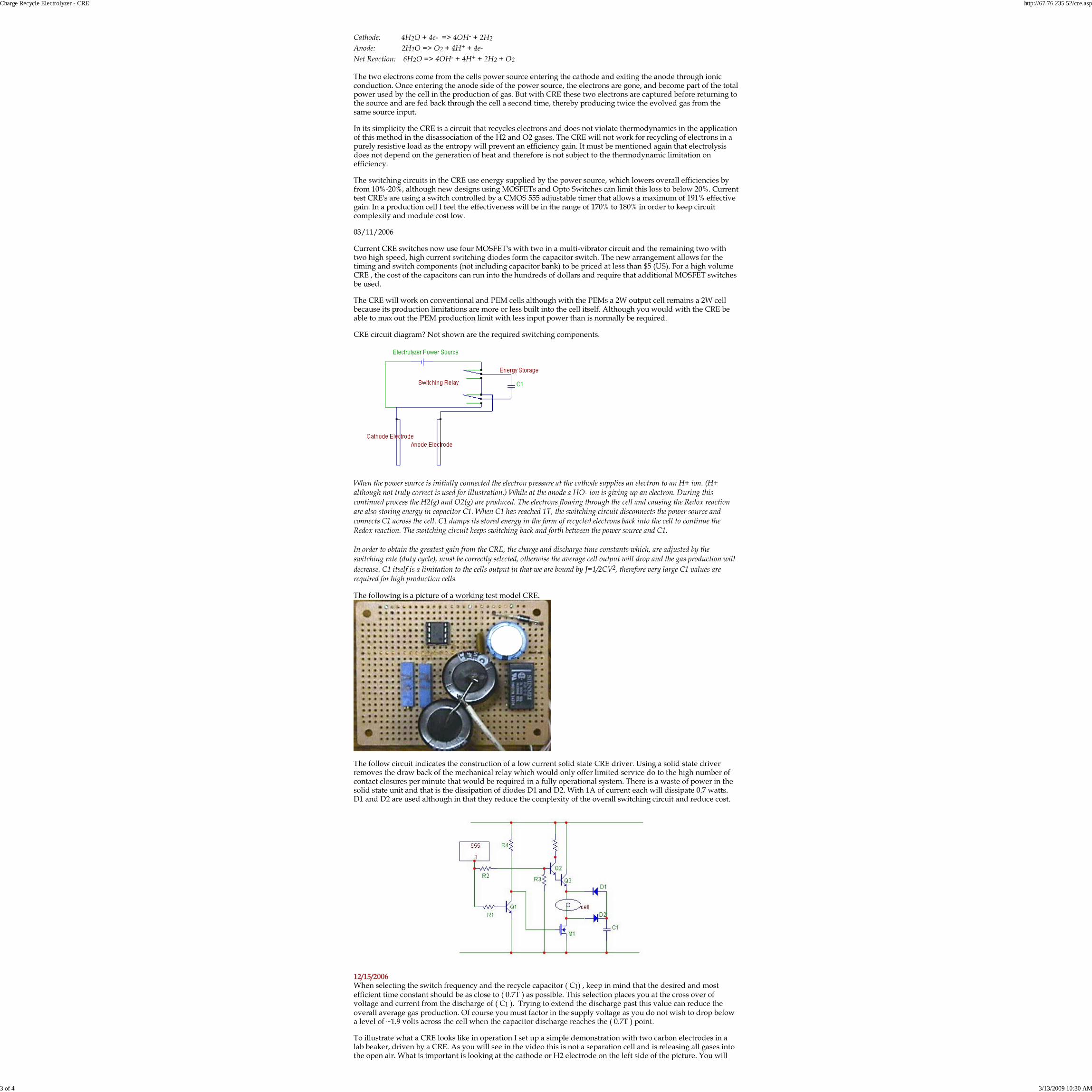
Cathode: 4H2O + 4e- => 4OH- + 2H2Anode: 2H2O => O2 + 4H+ + 4e-Net Reaction: 6H2O => 4OH- + 4H+ + 2H2 + O2
The two electrons come from the cells power source entering the cathode and exiting the anode through ionicconduction. Once entering the anode side of the power source, the electrons are gone, and become part of the totalpower used by the cell in the production of gas. But with CRE these two electrons are captured before returning tothe source and are fed back through the cell a second time, thereby producing twice the evolved gas from thesame source input.
In its simplicity the CRE is a circuit that recycles electrons and does not violate thermodynamics in the applicationof this method in the disassociation of the H2 and O2 gases. The CRE will not work for recycling of electrons in apurely resistive load as the entropy will prevent an efficiency gain. It must be mentioned again that electrolysisdoes not depend on the generation of heat and therefore is not subject to the thermodynamic limitation onefficiency.
The switching circuits in the CRE use energy supplied by the power source, which lowers overall efficiencies byfrom 10%-20%, although new designs using MOSFETs and Opto Switches can limit this loss to below 20%. Currenttest CRE's are using a switch controlled by a CMOS 555 adjustable timer that allows a maximum of 191% effectivegain. In a production cell I feel the effectiveness will be in the range of 170% to 180% in order to keep circuitcomplexity and module cost low.
03/11/2006
Current CRE switches now use four MOSFET's with two in a multi-vibrator circuit and the remaining two withtwo high speed, high current switching diodes form the capacitor switch. The new arrangement allows for thetiming and switch components (not including capacitor bank) to be priced at less than $5 (US). For a high volumeCRE , the cost of the capacitors can run into the hundreds of dollars and require that additional MOSFET switchesbe used.
The CRE will work on conventional and PEM cells although with the PEMs a 2W output cell remains a 2W cellbecause its production limitations are more or less built into the cell itself. Although you would with the CRE beable to max out the PEM production limit with less input power than is normally be required.
CRE circuit diagram? Not shown are the required switching components.
When the power source is initially connected the electron pressure at the cathode supplies an electron to an H+ ion. (H+although not truly correct is used for illustration.) While at the anode a HO- ion is giving up an electron. During thiscontinued process the H2(g) and O2(g) are produced. The electrons flowing through the cell and causing the Redox reactionare also storing energy in capacitor C1. When C1 has reached 1T, the switching circuit disconnects the power source andconnects C1 across the cell. C1 dumps its stored energy in the form of recycled electrons back into the cell to continue theRedox reaction. The switching circuit keeps switching back and forth between the power source and C1.
In order to obtain the greatest gain from the CRE, the charge and discharge time constants which, are adjusted by theswitching rate (duty cycle), must be correctly selected, otherwise the average cell output will drop and the gas production willdecrease. C1 itself is a limitation to the cells output in that we are bound by J=1/2CV2, therefore very large C1 values arerequired for high production cells.
The following is a picture of a working test model CRE.
The follow circuit indicates the construction of a low current solid state CRE driver. Using a solid state driverremoves the draw back of the mechanical relay which would only offer limited service do to the high number ofcontact closures per minute that would be required in a fully operational system. There is a waste of power in thesolid state unit and that is the dissipation of diodes D1 and D2. With 1A of current each will dissipate 0.7 watts.D1 and D2 are used although in that they reduce the complexity of the overall switching circuit and reduce cost.
12/15/2006When selecting the switch frequency and the recycle capacitor ( C1) , keep in mind that the desired and mostefficient time constant should be as close to ( 0.7T ) as possible. This selection places you at the cross over ofvoltage and current from the discharge of ( C1 ). Trying to extend the discharge past this value can reduce theoverall average gas production. Of course you must factor in the supply voltage as you do not wish to drop belowa level of ~1.9 volts across the cell when the capacitor discharge reaches the ( 0.7T ) point.
To illustrate what a CRE looks like in operation I set up a simple demonstration with two carbon electrodes in alab beaker, driven by a CRE. As you will see in the video this is not a separation cell and is releasing all gases intothe open air. What is important is looking at the cathode or H2 electrode on the left side of the picture. You will
Charge Recycle Electrolyzer - CRE http://67.76.235.52/cre.asp
3 of 4 3/13/2009 10:30 AM
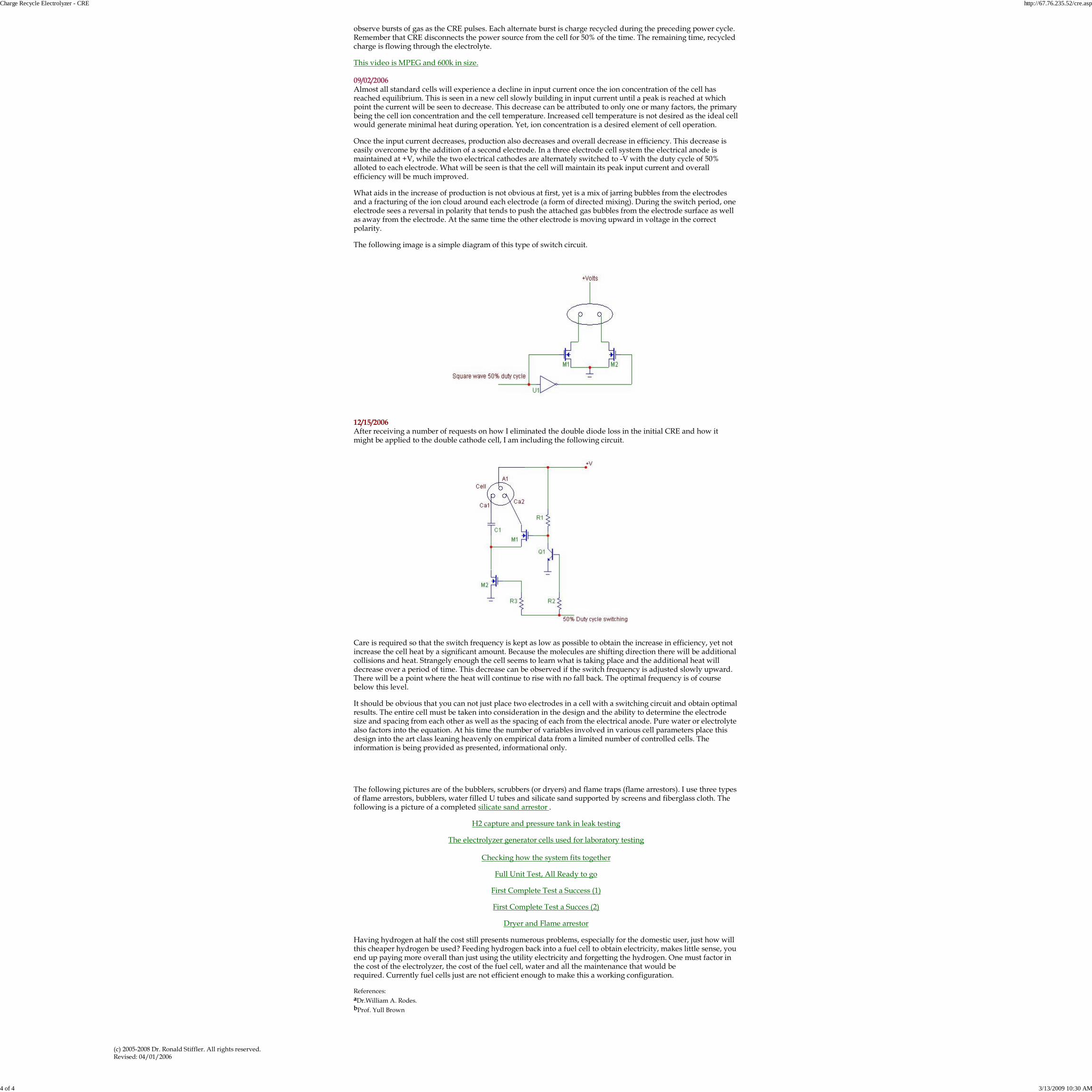
observe bursts of gas as the CRE pulses. Each alternate burst is charge recycled during the preceding power cycle.Remember that CRE disconnects the power source from the cell for 50% of the time. The remaining time, recycledcharge is flowing through the electrolyte.
This video is MPEG and 600k in size.
09/02/2006Almost all standard cells will experience a decline in input current once the ion concentration of the cell hasreached equilibrium. This is seen in a new cell slowly building in input current until a peak is reached at whichpoint the current will be seen to decrease. This decrease can be attributed to only one or many factors, the primarybeing the cell ion concentration and the cell temperature. Increased cell temperature is not desired as the ideal cellwould generate minimal heat during operation. Yet, ion concentration is a desired element of cell operation.
Once the input current decreases, production also decreases and overall decrease in efficiency. This decrease iseasily overcome by the addition of a second electrode. In a three electrode cell system the electrical anode ismaintained at +V, while the two electrical cathodes are alternately switched to -V with the duty cycle of 50%alloted to each electrode. What will be seen is that the cell will maintain its peak input current and overallefficiency will be much improved.
What aids in the increase of production is not obvious at first, yet is a mix of jarring bubbles from the electrodesand a fracturing of the ion cloud around each electrode (a form of directed mixing). During the switch period, oneelectrode sees a reversal in polarity that tends to push the attached gas bubbles from the electrode surface as wellas away from the electrode. At the same time the other electrode is moving upward in voltage in the correctpolarity.
The following image is a simple diagram of this type of switch circuit.
12/15/2006After receiving a number of requests on how I eliminated the double diode loss in the initial CRE and how itmight be applied to the double cathode cell, I am including the following circuit.
Care is required so that the switch frequency is kept as low as possible to obtain the increase in efficiency, yet notincrease the cell heat by a significant amount. Because the molecules are shifting direction there will be additionalcollisions and heat. Strangely enough the cell seems to learn what is taking place and the additional heat willdecrease over a period of time. This decrease can be observed if the switch frequency is adjusted slowly upward.There will be a point where the heat will continue to rise with no fall back. The optimal frequency is of coursebelow this level.
It should be obvious that you can not just place two electrodes in a cell with a switching circuit and obtain optimalresults. The entire cell must be taken into consideration in the design and the ability to determine the electrodesize and spacing from each other as well as the spacing of each from the electrical anode. Pure water or electrolytealso factors into the equation. At his time the number of variables involved in various cell parameters place thisdesign into the art class leaning heavenly on empirical data from a limited number of controlled cells. Theinformation is being provided as presented, informational only.
The following pictures are of the bubblers, scrubbers (or dryers) and flame traps (flame arrestors). I use three typesof flame arrestors, bubblers, water filled U tubes and silicate sand supported by screens and fiberglass cloth. Thefollowing is a picture of a completed silicate sand arrestor .
H2 capture and pressure tank in leak testing
The electrolyzer generator cells used for laboratory testing
Checking how the system fits together
Full Unit Test, All Ready to go
First Complete Test a Success (1)
First Complete Test a Succes (2)
Dryer and Flame arrestor
Having hydrogen at half the cost still presents numerous problems, especially for the domestic user, just how willthis cheaper hydrogen be used? Feeding hydrogen back into a fuel cell to obtain electricity, makes little sense, youend up paying more overall than just using the utility electricity and forgetting the hydrogen. One must factor inthe cost of the electrolyzer, the cost of the fuel cell, water and all the maintenance that would berequired. Currently fuel cells just are not efficient enough to make this a working configuration.
References:aDr.William A. Rodes.bProf. Yull Brown
(c) 2005-2008 Dr. Ronald Stiffler. All rights reserved.Revised: 04/01/2006
Charge Recycle Electrolyzer - CRE http://67.76.235.52/cre.asp
4 of 4 3/13/2009 10:30 AM