Embed Size (px)
Citation preview
NUCLEARINSTRUMENTS& METHODS
North-Holland
IN PHYSICSRESEARCH
Section A
Nuclear Instruments and Methods in Physics Research A 344 (1994) 319-334
The BES detectorJ.Z. Bai, Q . B1an, G.M. Chen, L.J . Chen, S.N . Chen, Y.Q . Chen, Z.Q . Chen, Y.K . Chi,H.C . Cui, X.Z . Cui, S.S . Deng, Y.W. Deng, H .L. Ding, B.Z . Dong, X.S . Dong, X. Du,Z.Z. Du, C. Feng, Z. Feng, Z.S . Fu, C.S . Gao, M .L. Gao, S.O . Gao, W.X . Gao, Y.N . Gao,S.D . Gu, W.X . Gu, Y.Z . Gitan, H.F . Guo, Y.N . Guo, Y.Y . Guo, S .W. Han, Y. Han, W. Hao,J . He, K.R. He, M.J . He, X.J . Hou, G.Y . Hu, J.S . Hu, J .W . Hu, D.Q . Huang, Y.Z . Hitang,Q.P . Jia, C.H . Jiang, Q . Ju, Y.F . Lai, P.F . Lang, D .S . Li, F . Li, H. Li, J1a Li, J .T . Li, Jin Li,L.L. Li, P.O . Li, Q.M. Li, R.B . Li, S.O . Li, W. Li, W.G. Li, Z.X . Li, G.N . L1ang, F.C . Lin,S.Z . Lin, W. Lin, Q . Liu, R.G . L1u, W. L1u, X. L1u, Z.A . L1u, Z.Y . L1u, C.G. Lu, W.D. Lu,Z.Y. Lu, J.G . Lu, D .H. Ma, E.C . Ma, J.M. Ma, H.S . Mao, Z.P . Mao, X.C. Meng, H.L . Ni,J . Nie, Z.D . Nie, W.P . Niu, L.J . Pan, N.D . Qi, J.J . Qian, Y.H . Ou, Y.K. Que, G. Rong,T.Z. Ritan, Y.Y . Shao, B.W. Shen, D.L. Shen, J . Shen, H .Y . Sheng, J .P . Sheng, H.Z . Shi,X.F . Song, H.S . Sun, F.K . Tang, S.O . Tang, W.H. T1an, F . Wang, G.Y. Wang, J .G . Wang,J.Y . Wang, L.S . Wang, L.Z. Wang, M. Wang, P. Wang, P .L. Wang, S.M . Wang, S .O. Wang,T.J. Wang, X.W. Wang, Y.Y. Wang, Z.H . Wang, Z.J . Wang, C.L . Wei, Z.Z . We1, J.W. Wu,S.H . Wu, S .O. Wu, W.M. Wu, X.D . Wu, Z.D . Wu, D.M . Xi, X.M . Xia, J . X1ao, P.P . Xie,X.X . X1e, J .G . Xu, R.S . Xu, Z.Q . Xu, B.C . Xitan, S .T . Xue, J . Yan, S.P . Yan, W.G . Yan,C.Z . Yang, C.M. Yang, C.Y. Yang, X.F . Yang, X.R . Yang, M .H. Ye, C.H . Yu, C.S . Yu,Z.Q . Yu, B .Y . Zhang, C.D . Zhang, C.C. Zhang, C.Y . Zhang, D .H. Zhang, G. Zhang,H.Y . Zhang, H.L . Zhang, J.W. Zhang, L.S . Zhang, S.O . Zhang, Y.P . Zhang, Y. Zhang,Y.M. Zhang, D .X . Zhao, J .W . Zhao, M. Zhao, P.D . Zhao, P .P . Zhao, W.R . Zhao, Z.G . Zhao,Z.Q . Zhao, J.P . Zheng, L.S . Zheng, M . Zheng, W.S . Zheng, Z.P . Zheng, G .P . Zhong,G.P . Zhou, H.S . Zhou, J . Zhou, Li Zhou, Lin Zhou, M. Zhou, Y.S . Zhou, Y.H. Zhou,G.S . Zhu, Q.M. Zhu, S.G . Zhu, Y.C . Zhu, Y.S . Zhu, B.A . ZhitangThe Institute of High Energy Physics, Beijing 100039, China
(Received 24 May 1993 ; revised form received 1 November 1993)
The Beijing Spectrometer (BES) is a general purpose solenoidal detector at the Beijing Electron Positron Collider (BEPC) . It isdesigned to study exclusive final states in e' e - annihilations at the center of mass energy from 3.0 to 5.6 GeV. This requires largesolid angle coverage combined with good charged particle momentum resolution, good particle identification and high photondetection efficiency at low energies . In this paper we describe the construction and the performance of BES detector .
1. Introduction
The Beijing Spectrometer (BES) is a large generalpurpose solenoidal detector at the Beijing ElectronPositron Collider (BEPC) [1] . The beam energy ofBEPC is in the range from 1 .5 to 2.8 GeV with adesign luminosity at 5.6 GeV center of mass energy of1 .7 X 1031 CM-2 s -1 . The main physics goal is to studythe charm and r physics. In order to fully reconstruct
016&9002/94/$07 00 © 1994 - Elsevier Science B.V. All rights reservedSSDI0168-9002(93)EI248-V
all the particles produced in e + e - annihilations, BESmust have large solid angle coverage, good momentumresolution and particle identification for charged parti-cles, good position resolution and adequate energyresolution for photons and high detection efficiency forlow energy photons.
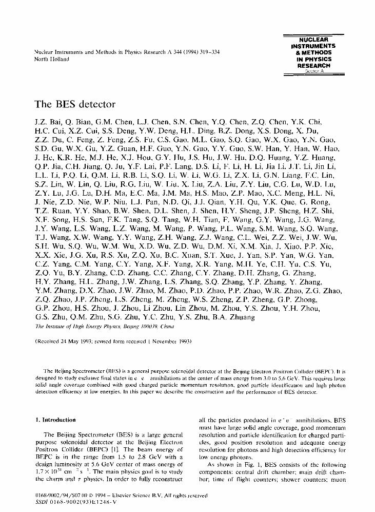
As shown in Fig. 1, BES consists of the followingcomponents : central drift chamber; main drift cham-ber; time of flight counters ; shower counters ; muon
320
chambers ; luminosity monitor; solenoidal magnet ; elec-tronics and its calibration system; trigger; on-line dataacquisition and data monitoring system .
The design and prototype testing began at early of1982 . Construction of detector components was startedin 1985 and completed in 1988 . In October of 1988, theassembling of the spectrometer was completed and thefirst cosmic ray event was obtained . In April of 1989,after a period of cosmic ray test, the detector wasmoved into the beam line . The whole system waschecked out and calibrated in the fall of 1989 . Physicsruns began in January of 1990. Since then about ninemillion J/+G events have been collected. In the follow-ing year, a scan of the beam energy across the 7-production threshold allowed us to perform a precisionmeasurement of the r mass . Data has also been takenat 4.03 GeV for studies of the Ds meson.
The sections below will describe the detailed struc-ture of BES detector and its performance.
2. Magnet
J. Z. Bac et al. /Nuel. Instr. and Meth. in Phys. Res. A 344 (1994) 319-334
The solenoidal magnet is composed of a conven-tional coil and an iron return yoke, which is also themain structural support for the apparatus. This magnetcan produce a uniform axial magnetic field of 4.0 kGover the volume of the drift chambers . The electromag-netic shower counters are placed inside the coil to
m
mm
icy
101080 mom
I éI9~n
=u
I~~_ ~7
ilIN
MM008NNIMENESOMEM MEN
rl\ \ \1 \\\ \ \ \ \\\ \ \ \\\\\\\\\ \ \ \\ i
ILJ\ \\\\\\\\\\\\\7
E-H
Fig 1 . Side view of the BES detector.
keep the amount of material in front of them as littleas possible . The iron structure is divided into barreland endcap parts. The barrel part has three layers ofiron with two layers of muon chambers mounted on theoutside of each layer . The inner two iron layers func-tion as the magnetic flux return as well as being hadronabsorbers. The whole iron structure is 5 .1 m long, 6.65m wide and 5.86 m high ; and it weighs 330 tons.
The coil uses an extruded aluminum conductor withan outside dimension of 52 mm by 52 mm. It contains acentral hole, 27 mm in diameter, for cooling water. Thecoil was winded with two conductors of the samelength side by side to produce a bifilar structure withsix layers . There are 381 turns. Insulation betweenadjacent layers is achieved using Mylar tapes, DMDand special insulation strips . The inner and outer di-ameter of the coil are 3.478 and 4.135 m respectively,the coil is 3 .617 m long . The power and water connec-tions are made at the ends of the coil, with the layersconnected in series electrically, and in parallel forwater flow . The coil is mounted to the inside of theiron structure by two 12 mm thick metal belts whichallow expansion of the coil due to temperature change .To reduce the effect of temperature change in the coilon other detector components, there is a water coolingcylindrical shield between the coil and the barrelshower counters .
The magnetic field was measured using three Hallprobes mounted on an arm which could be rotated
Muon CounterIron YokeSolenoidBarrel Shower CounterTime of Flight CounterMain Drift ChamberCentral Drift ChamberBeam PipeQuadrupole
Luminosity Monitor-Endcap Shower Counter
Endcap TOF Counter
1 m
about the magnetic axis . Measurements of the radial,longitudinal and azimuthal components of the fieldwere taken at points with fixed steps in three direc-tions. The field was calibrated with an NMR magne-tometer at the center of the magnet . The measuredfield map was fit with polynomials in two dimensions ;inside the volume of the main drift chamber, the varia-tion of the axial field component is less than 0.2%.
3. Beam pipe and multiple scattering
J.Z. Bat et al. /Nucl. Instr and Meth . in Phys. Res. A 344 (1994) 319-334
In order to reduce multiple scattering for chargedparticles, the beam pipe should be as thin as possibleand made from a material with low atomic number .Limited by available material in China at that time, wehave used a 2 mm thick aluminum tube, which corre-sponds to 2.25 X 10⁻² radiation length (H.), with anouter diameter of 150 mm. We plan to change it to aberyllium beam pipe in 1995 .
The total material in the beam pipe, the inner andouter wall of central drift chamber, the inner wall ofmain drift chamber and the gas and wires in the driftchambers, corresponds to 6.46 X 10 -'- r .l . at 90° to thebeam axis .
4. Central drift chamber
Just outside the beam pipe is the central driftchamber (CDC). It is used to improve the tracking
5. Main drift chamber
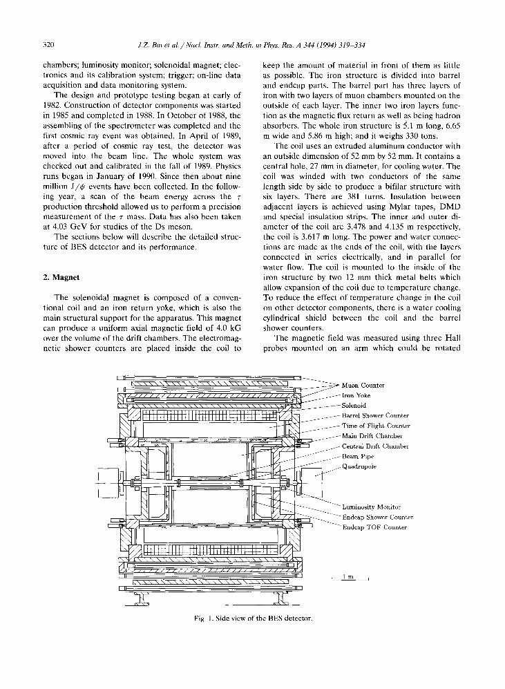
Fig . 2. Cell structure of the main drift chamber.
321
acceptance and momentum resolution when used inconjunction with the main drift chamber. It is also usedin the trigger to reduce the cosmic ray background .
The CDC is a concentric cylindrical chamber of1100 mm long . Its inner and outer diameters are 184and 298 mm respectively . The inner and outer wallsare 2 and 1 mm thick, both are made of carbon-fiber .On each inside surface of inner and outer walls there isa 50 wm aluminum foil to shield the chamber electri-cally. The end plates are 12 mm thick aluminum . Thechamber consists of four layers of sense wires with 48wires per layer . Two field wires are between neighbor-ing sense wires in a layer, forming a hexagonal driftcell . The cells are offset by half a cell in alternativelayers to resolve the left-right ambiguity. The radialseparation between sense wire layers is 12 mm. Thesense wire is made of 38 wm stainless steel, and thefield wire is 178 ptm gold plated BeCu . The signals areread out from both ends of the wires to allow zdetermination by charge division . The gas used is amixture of Ar/COZ/CH4 = 89/10/1, the flow rate isabout three volumes per day. The single wire positionresolution in r-(h plane is about 220 p,m. The zresolution is 0.8% of the full length .
Main drift chamber (MDC) is a large precise driftchamber [2], which is the heart of BES detector . It is
32 2
used to measure the trajectory of charged tracks, theirmomenta and their dE/dx.
5.1 . The structure
JZ. Bai et al. /Nucl. Instr. and Meth . in Phys. Res. A 344 (1994) 319-334
MDC is also a concentric cylindrical chamber sur-rounding CDC. Its inner and outer diameters are 310and 2300 mm respectively, the effective length is 2120mm. The inner wall is made of 2 mm carbon-fiberplastic, corresponding to 9 x 10⁻³ r.l ., the outer wall isof 10 mm thick aluminum . The two end plates aremade of 40 mm thick aluminum . On the inside surfaceof the cylinder walls there is a 50 wm copper platedKapton film .
There are ten tracking layers in MDC. The wires ineven layers are parallel to the chamber axis, calledaxial wires; the wires in odd layers have a small anglewith respect to the cylinder axis to provide stereoinformation . These stereo wires are used to determinethe coordinate of tracks along the z-axis . The numberof cells per layer varies from 48 in the innermost to 108in the outermost, for a total of 702. Fig. 2 shows thestructure of MDC.
Each cell of MDC has four sense wires, the radialseparation between neighboring sense wires is 10 mm.Altogether there are 2808 sense wires, and a total of19 380 wires (including sense wires, field wires, poten-tial wires and protection wires) . The signals on sensewires are used to determine the drift time (to deter-mine the position of the track trajectory) and thecharge collected (dE/dx). In order to resolve theleft-right ambiguity, the sense wires are staggered 350wm to the left or to the right alternatively from thefiducial center line of the cell . Potential wires betweenthe sense wires reduce the cross-talk between neigh-boring wires and reduce the electrostatic repulsionforces between sense wires. They are also used tocontrol the sense wire gain . To improve the uniformityof the electric field at the ends of the cells, there areadditional wires called protection wires. The field wiresform the boundary of the cells, the interval betweenwires is 5 mm. Since the cell is of wedge shape, thenominal half width of the cells is specified at theirradial center . Table 1 shows the cell dimensions . Theinner cells are designed to have smaller size to reducethe rate of multiple hits in a cell ; the cell size of outerlayers is determined by the desire for good spaceresolution, which is mainly limited by diffusion . Table 2gives a description of the wires used in MDC.
This cell structure is designed to provide a constantelectric field over as much of the cell as possible. Thisis required if we are to have good spatial resolutionand uniform dE/dx sampling . This structure alsomakes the time to space conversion and track recon-struction easier . The merit of multiple-sense-wires cellis the ability to effectively reject the backgrounds and
Table 1Geometry of MDC cells
noises by the time correlation of wires in a cell . Ashortcoming is that it is likely to induce negative sig-nals in neighboring channels to a hit wire . We haveintroduced a method of adding a resistor couplingnetwork between sense wires, in doing so a fraction ofthe original signal is used to compensate the inducedsignal . As a result, the cross-talk is reduced to less than1% .
5.2. Working gas
The gas used in MDC is a mixture of Ar/COZ/CH4 = 89/10/1 . The gas gain is set to about 5 x 10⁴by proper high voltage setting on the field wires andpotential wires. The drift velocity is saturated at about5 cm/ws when the electric field reaches 700 V/cm ; thediffusion coefficient is 100 wm/ cm ; the most proba-ble energy loss of minimum ionizing particles is 1 .37keV/cm . The gas flow rate is about half a volume perday.
5.3 . Performance
The solid angle coverage for particles passingthrough layer 2 is 95% of 4 , Tr, it is 90% for particlesthrough layer 4, and 70% for layer 10 . The wire effi-ciency is typically above 95% and the single wire posi-
Table 2Wire parameters used in MDC
Layer Radial[mm]
Number ofcells
Halfwidth[mm]
I 215 48 14 .1II 295 48 19 .3III 375 60 19 .6IV 475 48 31 .1V 575 58 311VI 675 68 31 .2VII 775 78 31 .2VIII 875 88 31 .2lx 975 98 31 .2X 1075 108 31 .2
Wire Diameter Material Wire[wm] tension
[8]Sense 30 Gold plated W 100Potential 100 Gold plated Fe-Ni-Cr 500Protection 100 Gold plated Fe-Ni-Cr 500Field 178 Gold plated Be-Cu 500Thick field 220 Gold plated Be-Cu 600
3000
2500
2000
1500
1000
500
6. Time of flight counters (TOF)
J.Z. Bai et al. /Nucl. Instr. and Meth. in Phys. Res. A 344 (1994) 319-334
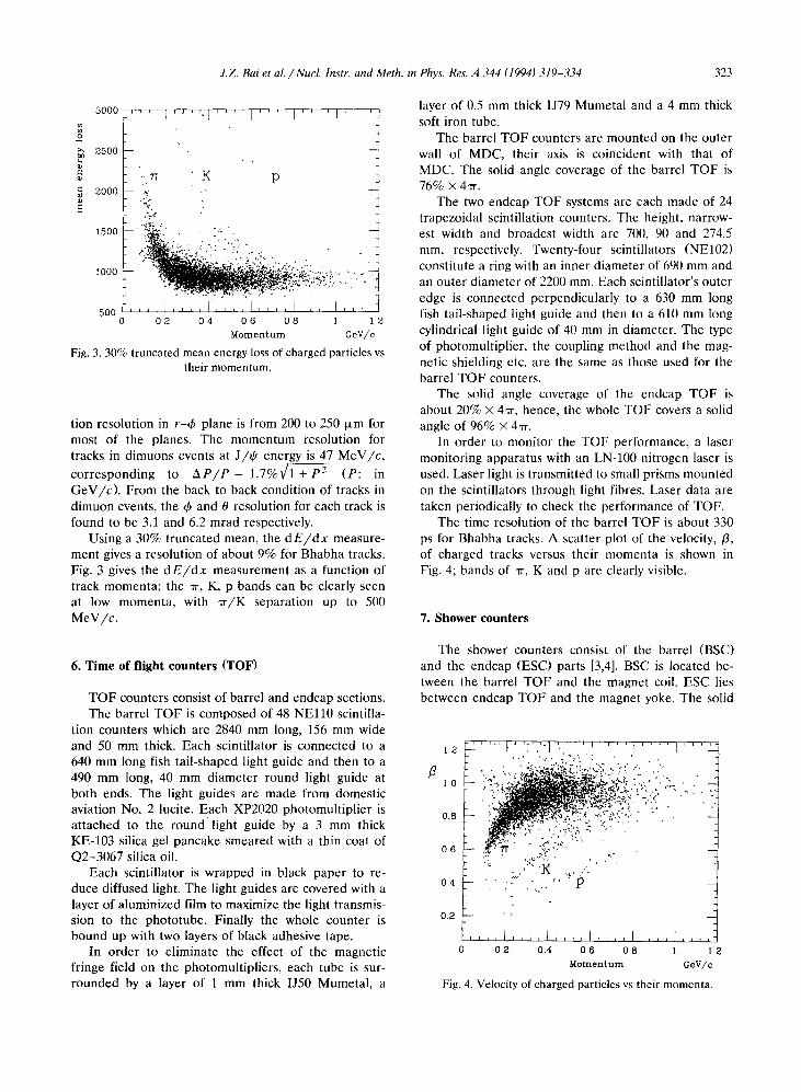
Fig . 3. 30% truncated mean energy loss of charged particles vstheir momentum .
tion resolution in r-O plane is from 200 to 250 Rm formost of the planes. The momentum resolution fortracks in dimuons events at J/0 energy is 47 MeV/c,corresponding to AP/P = 1 .7% 1 + P 2 (P : inGeV/c) . From the back to back condition of tracks indimuon events, the ¢ and 0 resolution for each track isfound to be 3.1 and 6.2 mrad respectively .
Using a 30% truncated mean, the dE/dx measure-ment gives a resolution of about 9% for Bhabha tracks .Fig. 3 gives the dE/dx measurement as a function oftrack momenta; the -rr, K, p bands can be clearly seenat low momenta, with -rr/K separation up to 500MeV/c.
TOF counters consist of barrel and endcap sections.The barrel TOF is composed of 48 NE110 scintilla-
tion counters which are 2840 mm long, 156 mm wideand 50 mm thick. Each scintillator is connected to a640 mm long fish tail-shaped light guide and then to a490 mm long, 40 mm diameter round light guide atboth ends . The light guides are made from domesticaviation No . 2 Lucite . Each XP2020 photomultiplier isattached to the round light guide by a 3 mm thickKE-103 silica gel pancake smeared with a thin coat ofQ2-3067 silica oil .
Each scintillator is wrapped in black paper to re-duce diffused light. The light guides are covered with alayer of aluminized film to maximize the light transmis-sion to the phototube. Finally the whole counter isbound up with two layers of black adhesive tape .
In order to eliminate the effect of the magneticfringe field on the photomultipliers, each tube is sur-rounded by a layer of 1 mm thick IJ50 Mumetal, a
layer of 0.5 mm thick IJ79 Mumetal and a 4 mm thicksoft iron tube .
The barrel TOF counters are mounted on the outerwall of MDC, their axis is coincident with that ofMDC. The solid angle coverage of the barrel TOF is76% x 4,rr .
The two endcap TOF systems are each made of 24trapezoidal scintillation counters . The height, narrow-est width and broadest width are 700, 90 and 274.5mm, respectively. Twenty-four scintillators (NE102)constitute a ring with an inner diameter of 690 mm andan outer diameter of 2200 mm. Each scintillator's outeredge is connected perpendicularly to a 630 mm longfish tail-shaped light guide and then to a 610 mm longcylindrical light guide of 40 mm in diameter. The typeof photomultiplier, the coupling method and the mag-netic shielding etc. are the same as those used for thebarrel TOF counters.
The solid angle coverage of the endcap TOF isabout 20% X 4-rr, hence, the whole TOF covers a solidangle of 96% X 4,rr .
In order to monitor the TOF performance, a lasermonitoring apparatus with an LN-100 nitrogen laser isused . Laser light is transmitted to small prisms mountedon the scintillators through light fibres . Laser data aretaken periodically to check the performance of TOF.
The time resolution of the barrel TOF is about 330ps for Bhabha tracks . A scatter plot of the velocity, /3,of charged tracks versus their momenta is shown inFig. 4; bands of -rr, K and p are clearly visible .
7 . Shower counters
The shower counters consist of the barrel (BSC)and the endcap (ESC) parts [3,4] . BSC is located be-tween the barrel TOF and the magnet coil . ESC liesbetween endcap TOF and the magnet yoke . The solid
12
0 .s
0s
04
0 .2
0 02 0 .4 06 08 1 12Momentum GeV/c
Fig. 4. Velocity of charged particles vs their momenta.
323
324 1Z. Bai et al. / Nucl Instr. and Meth . i n Phys . Res . A 344 (1994) 319-334
angle coverage of BSC is 80% X 4,rr and that of ESC is13% x 4-rr .BSC is a cylindrical detector consisting of twenty-
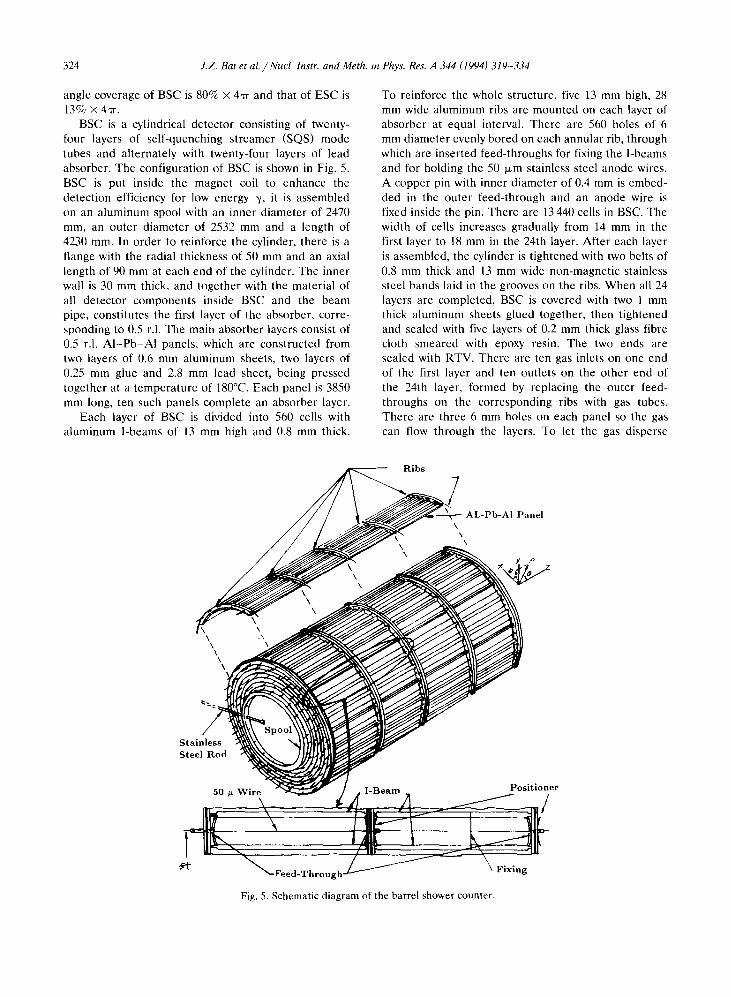
four layers of self-quenching streamer (SQS) modetubes and alternately with twenty-four layers of leadabsorber . The configuration of BSC is shown in Fig. 5 .BSC is put inside the magnet coil to enhance thedetection efficiency for low energy y, it is assembledon an aluminum spool with an inner diameter of 2470mm, an outer diameter of 2532 mm and a length of4230 mm. In order to reinforce the cylinder, there is aflange with the radial thickness of 50 mm and an axiallength of 90 mm at each end of the cylinder. The innerwall is 30 mm thick, and together with the material ofall detector components inside BSC and the beampipe, constitutes the first layer of the absorber, corre-sponding to 0.5 r.l . The main absorber layers consist of0.5 r.l . Al-Pb-AI panels, which are constructed fromtwo layers of 0.6 mm aluminum sheets, two layers of0.25 mm glue and 2.8 mm lead sheet, being pressedtogether at a temperature of 180°C. Each panel is 3850mm long, ten such panels complete an absorber layer .
Each layer of BSC is divided into 560 cells withaluminum I-beams of 13 mm high and 0.8 mm thick .
Fig . 5 . Schematic diagram of the barrel shower counter.
To reinforce the whole structure, five 13 mm high, 28mm wide aluminum ribs are mounted on each layer ofabsorber at equal interval . There are 560 holes of 6mm diameter evenly bored on each annular rib, throughwhich are inserted feed-throughs for fixing the I-beamsand for holding the 50 wm stainless steel anode wires.A copper pin with inner diameter of 0.4 mm is embed-ded in the outer feed-through and an anode wire isfixed inside the pin. There are 13 440 cells in BSC. Thewidth of cells increases gradually from 14 mm in thefirst layer to 18 mm in the 24th layer . After each layeris assembled, the cylinder is tightened with two belts of0.8 mm thick and 13 mm wide non-magnetic stainlesssteel bands laid in the grooves on the ribs . When all 24layers are completed, BSC is covered with two 1 mmthick aluminum sheets glued together, then tightenedand sealed with five layers of 0.2 mm thick glass fibrecloth smeared with epoxy resin . The two ends aresealed with RTV. There are ten gas inlets on one endof the first layer and ten outlets on the other end ofthe 24th layer, formed by replacing the outer feed-throughs on the corresponding ribs with gas tubes.There are three 6 mm holes on each panel so the gascan flow through the layers . To let the gas disperse
J.Z. Bai et al. /Nuel. Instr. and Meth in Phys. Res A 344 (1994) 319-334
transversely each feed-through also has a 1 .5 mm hole .The gas is a mixture of 80% Ar and 20% COz, which isbubbled through 4°C n-pentane, giving an n-pentaneconcentration in the final mixture of about 25%. Thegas flow rate is one volume per three days.ESC is made up of 24 layers of discrete square SQS
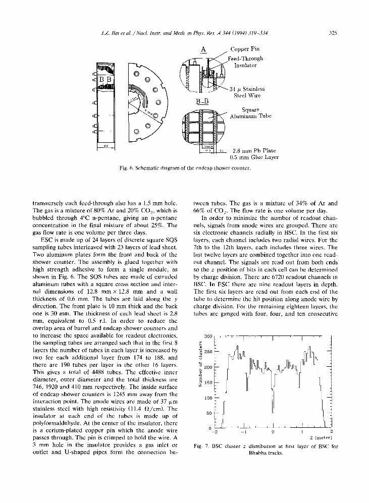
sampling tubes interleaved with 23 layers of lead sheet.Two aluminum plates form the front and back of theshower counter. The assembly is glued together withhigh strength adhesive to form a single module, asshown in Fig. 6. The SQS tubes are made of extrudedaluminum tubes with a square cross section and inter-nal dimensions of 12.8 mm x 12.8 mm and a wallthickness of 0.6 mm. The tubes are laid along the ydirection. The front plate is 10 mm thick and the backone is 30 mm. The thickness of each lead sheet is 2.8mm, equivalent to 0.5 r.l . In order to reduce theoverlap area of barrel and endcap shower counters andto increase the space available for readout electronics,the sampling tubes are arranged such that in the first 8layers the number of tubes in each layer is increased bytwo for each additional layer from 174 to 188, andthere are 190 tubes per layer in the other 16 layers .This gives a total of 4488 tubes. The effective innerdiameter, outer diameter and the total thickness are746, 1920 and 410 mm respectively. The inside surfaceof endcap shower counters is 1245 mm away from theinteraction point. The anode wires are made of 37 wmstainless steel with high resistivity (11.4 SZ/cm) . Theinsulator at each end of the tubes is made up ofpolyformaldehyde . At the center of the insulator, thereis a cerium-plated copper pin which the anode wirepasses through. The pin is crimped to hold the wire . A3 mm hole in the insulator provides a gas inlet oroutlet and U-shaped pipes form the connection be-
B-B
A
300
250
A
150Z
loo
50
Copper Pin
Feed-ThroughInsulator
34 / StainlessSteel Wire
Fig. 6. Schematic diagram of the endcap shower counter.
SquareAluminum Tube
2.8 turn Pb Plate0.5 mm Glue Layer
tween tubes. The gas is a mixture of 34% of Ar and66% of CO, The flow rate is one volume per day.
In order to minimize the number of readout chan-nels, signals from anode wires are grouped. There aresix electronic channels radially in BSC. In the first sixlayers, each channel includes two radial wires. For the7th to the 12th layers, each includes three wires. Thelast twelve layers are combined together into one read-out channel. The signals are read out from both endsso the z position of hits in each cell can be determinedby charge division . There are 6720 readout channels inBSC. In ESC there are nine readout layers in depth.The first six layers are read out from each end of thetube to determine the hit position along anode wire bycharge division . For the remaining eighteen layers, thetubes are ganged with four, four, and ten consecutive
jjol~
o ~ 11 1
-2
-1
0
1
2Z (meter)
325
Fig. 7. BSC cluster z distribution at first layer of BSC forBhabha tracks .
326 J.Z. Bai et al. /Nucl. Instr. and Meth . to Phys. Res A 344 (1994) 319-334
3000
2500
2000
1500
1000
500
0
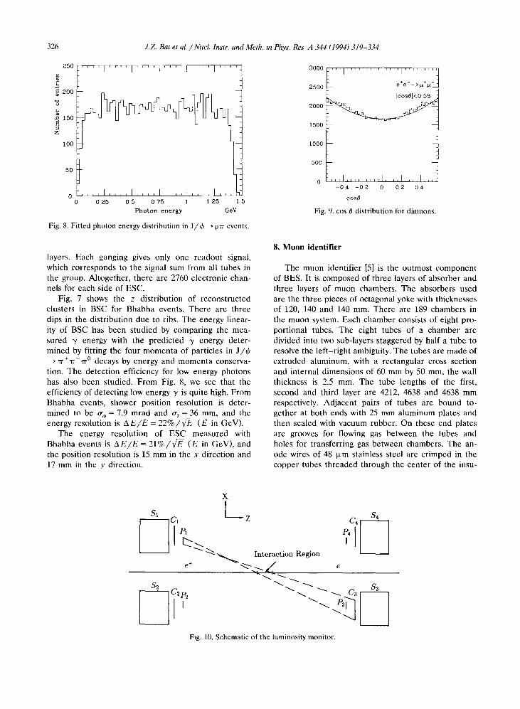
Fig. 8. Fitted photon energy distribution in J/0 - pir events .
layers . Each ganging gives only one readout signal,which corresponds to the signal sum from all tubes inthe group. Altogether, there are 2760 electronic chan-nels for each side of ESC.
Fig. 7 shows the z distribution of reconstructedclusters in BSC for Bhabha events . There are threedips in the distribution due to ribs . The energy linear-ity of BSC has been studied by comparing the mea-sured y energy with the predicted y energy deter-mined by fitting the four-momenta of particles in J/tP~Tr +Tr-,RO decays by energy and momenta conserva-tion . The detection efficiency for low energy photonshas also been studied. From Fig. 8, we see that theefficiency of detecting low energy y is quite high . FromBhabha events, shower position resolution is deter-mined to be Qm = 7.9 mrad and Qz = 36 mm, and theenergy resolution is AEIE = 22%/ v'E-- (E in GeV).
The energy resolution of ESC measured withBhabha events is AE/E = 21%/V (E in GeV), andthe position resolution is 15 mm in the x direction and17 mm in the y direction.
Si
DS2
C2 P2
Z
8, Muon identirier
a
Interaction Region
Fig . 10. Schematic of the luminosity monitor.
-04 -02 0 02 04
cose
Fig . 9 . cos 0 distribution for dimuons.
The muon identifier [5] is the outmost componentof BES. It is composed of three layers of absorber andthree layers of muon chambers . The absorbers usedare the three pieces of octagonal yoke with thicknessesof 120, 140 and 140 mm. There are 189 chambers inthe muon system . Each chamber consists of eight pro-portional tubes. The eight tubes of a chamber aredivided into two sub-layers staggered by half a tube toresolve the left-right ambiguity. The tubes are made ofextruded aluminum, with a rectangular cross sectionand internal dimensions of 60 mm by 50 mm, the wallthickness is 2.5 mm. The tube lengths of the first,second and third layer are 4212, 4638 and 4638 mmrespectively . Adjacent pairs of tubes are bound to-gether at both ends with 25 mm aluminum plates andthen sealed with vacuum rubber . On these end platesare grooves for flowing gas between the tubes andholes for transferring gas between chambers . The an-ode wires of 48 [Lm stainless steel are crimped in thecopper tubes threaded through the center of the insu-
é
S4
D
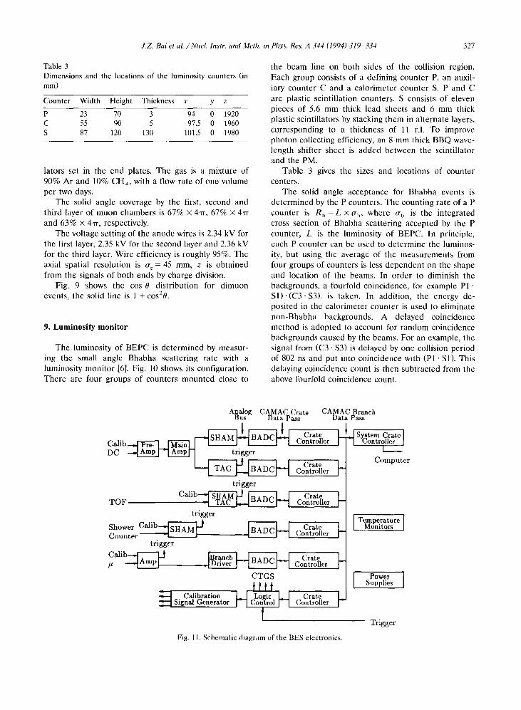
Table 3Dimensions and the locations of the luminosity counters (inmm)
lators set in the end plates . The gas is a mixture of90% Ar and 10% CH4, with a flow rate of one volumeper two days.
The solid angle coverage by the first, second andthird layer of muon chambers is 67% X 4-rr, 67% X 4,rrand 63% X 4, rr, respectively .
The voltage setting of the anode wires is 2.34 kV forthe first layer, 2.35 kV for the second layer and 2.36 kVfor the third layer. Wire efficiency is roughly 95% . Theaxial spatial resolution is o,z = 45 mm, z is obtainedfrom the signals of both ends by charge division .
Fig. 9 shows the cos 0 distribution for dimuonevents, the solid line is 1 + cos20.
9. Luminosity monitor
The .luminosity of BEPC is determined by measur-ing the small angle Bhabha scattering rate with aluminosity monitor [6] . Fig. 10 shows its configuration .There are four groups of counters mounted close to
J.Z. Bai et al. /Noel. Instr. and Meth. i n Phys . Res . A 344 (1994) 319-334
the beam line on both sides of the collision region .Each group consists of a defining counter P, an auxil-iary counter C and a calorimeter counter S. P and Care plastic scintillation counters. S consists of elevenpieces of 5.6 mm thick lead sheets and 6 mm thickplastic scintillators by stacking them in alternate layers,corresponding to a thickness of 11 r.l . To improvephoton collecting efficiency, an 8 mm thick BBQ wave-length shifter sheet is added between the scintillatorand the PM.
Table 3 gives the sizes and locations of countercenters.
The solid angle acceptance for Bhabha events isdetermined by the P counters . The counting rate of a Pcounter is Rt, = L X Q i� where ut, is the integratedcross section of Bhabha scattering accepted by the Pcounter, L is the luminosity of BEPC. In principle,each P counter can be used to determine the luminos-ity, but using the average of the measurements fromfour groups of counters is less dependent on the shapeand location of the beams. In order to diminish thebackgrounds, a fourfold coincidence, for example P1 ,S1) - (C3 - S3), is taken. In addition, the energy de-posited in the calorimeter counter is used to eliminatenon-Bhabha backgrounds. A delayed coincidencemethod is adopted to account for random coincidencebackgrounds caused by the beams. For an example, thesignal from (C3 - S3) is delayed by one collision periodof 802 ns and put into coincidence with (PI - S1). Thisdelaying coincidence count is then subtracted from theabove fourfold coincidence count.
Analog CAMAC Crate
CAMAC BranchBus
Data Pass
Data Pass
Fig . 1 1 . Schematic diagram of the BES electronics .
TemperatureMonitors
PowerSupplies
327
Counter Width Height Thickness x y zP 23 70 3 94 0 1920C 55 90 5 97 .5 0 1960S 87 120 130 101 .5 0 1980
32 8
10 . Electronics
J.Z. Bai et al. /Nucl. Instr. and Meth . in Phys. Res. A 344 (1994) 319-334
The accuracy of the luminosity measurement shouldbe better than 3% .
The basic functions of the electronics system [7]may be described as follows:
- To receive the signals from various detector com-ponents; to process these signals with high speed andaccuracy ; to buffer the processed signals while some ofthe information are sent to the trigger system .
- To respond to a trigger decision: to reset theelectronics if the trigger rejects an event; or to digitizethe signals, preprocess the data and finally to requestthe on-line computer to read the data out if the triggeraccepts an event.
- To calibrate the electronic system routinely toensure good data quality .
- To receive the time reference signals from BEPCand the trigger logic.
The basic block diagram of BES electronics is shownin Fig. 11 . All the signals from various detector compo-nents are temporarily stored in the form of a voltagelevel after signal processing. They are digitized or theelectronics is reset according to the trigger decision . Itis cost effective to use an analog bus and an intelligentADC (BADC) to do data pre-processing, since thepercentage of channels with useful data is small. TheBADC performs the following functions:
- Data suppression . The channels without usefuldata are not read out.
- Data correction for electronic gain, pedestal andsecond order integral nonlinearity of each channel.
- Address assignment for each channel to facilitatethe off-line data processing .
The drift chamber readout is achieved by preampli-fiers mounted directly on the chamber. These areconnected by double shielded twisted pair cables ofabout 5 m long to the main amplifiers, which arelocated on the outside face of the iron yoke . Thisarrangement helps to increase the common mode re-jection ratio and to reduce the interference betweenchannels . The main amplifier increases the signal am-plitude and reduces the decay time of the signal bypole-zero cancellation . The signal is split into two, onefor time measurement and the other for charge mea-surement . The signals are transmitted to the TDC andADC modules in the electronics room by 28 m longtwisted pair cables . The signal for the time measure-ment is produced by a low threshold leading edgediscriminator . The measurement of the drift time isdone by a TAC working in a common stop mode . Thecommon stop signal is obtained either from triggerlogic in data acquisition mode or from calibrationcircuit in calibration mode . The time measured is tem-
porarily stored in the voltage form . The charge mea-surement is done by an integrated sample and hold(SHAM) circuit, then also temporarily stored in thevoltage form .
For the TOF readout, a reference signal is pickedup from the button shaped electrode of the beammonitor which is located on the beam line about 9.3 maway from the interaction point. It is transmitted to thetiming module by a coaxial cable with good high fre-quency properties of about 28 m long . It is shaped by aleading edge discriminator and then delayed by a fixedtime to be used as the common stop signal for timingmeasurement. Since the electron /positron bunch has acertain length and the beam intensity varies with time,the time jitter of this common stop signal will havenon-negligible contribution to the time resolution ofthe TOF system . The signal from the PM is transmit-ted to the electronics modules by coaxial cable of about30 m long . The signal from each PM is split into two.One is shaped by a leading edge discriminator andthen sent to a TAC as a start signal to measure thetime, the other is integrated to record the charge . As inthe MDC, both timing and charge are temporarilystored in the sample and hold circuit to be digitizedonly if the event is accepted . The charge recorded willbe used in the off-line analyses to correct the measuredtime .
For the shower counter readout, the signal ampli-tude is quite large since the shower counter is workingin the SOS mode . Signals are sent to the integratedSHAM circuit directly without any amplification . Inorder to increase the packing density and reduce thevoltage drop, the SHAM circuit is constructed usinghybrid chip designed at our institute . The SHAM mod-ules are mounted in crates at the ends of BES detec-tor, thus avoiding large numbers of long cables . For thetrigger purpose, analog sums are formed from everytwelve signal channels in two neighboring cells .
The muon counter readout uses charge sensitivepreamplifiers . The output of the preamplifier is sent tothe tracking SHAM circuit, also a self-designed hybrid,in which the signal is temporarily stored in the voltageform . The preamplifiers and the tracking SHAMS areassembled in a front-end box, directly mounted on theend of muon counters . The output from the front-endbox is then digitized by BADC.A set of well designed calibration circuits and the
corresponding calibration methods have been devel-oped . This allows us to monitor the uniformity of thethousands of channels and to reduce the precisionrequirements for the electronic components . This sys-tem gives us the capability to check the entire elec-tronic system frequently .
The BES electronic system is working in an environ-ment with strong wide-band interference from the col-lider. In order to increase the electromagnetic compat-
J.Z Bai et al. /Nucl. Instr. and Meth . in Phys . Res. A 344 (1994) 319-334
ibility, much attention was paid to the signals connec-tions, the grounding and shielding of the electronics,the filtering and isolation of the power supply system .
Stringent quality control during the construction ofthe system has greatly reduced the time spent onsystem debugging. Components were inspected andtested at each stage of assembly, so that in the finalsystem a high percentage of the channels performed todesigned specifications .
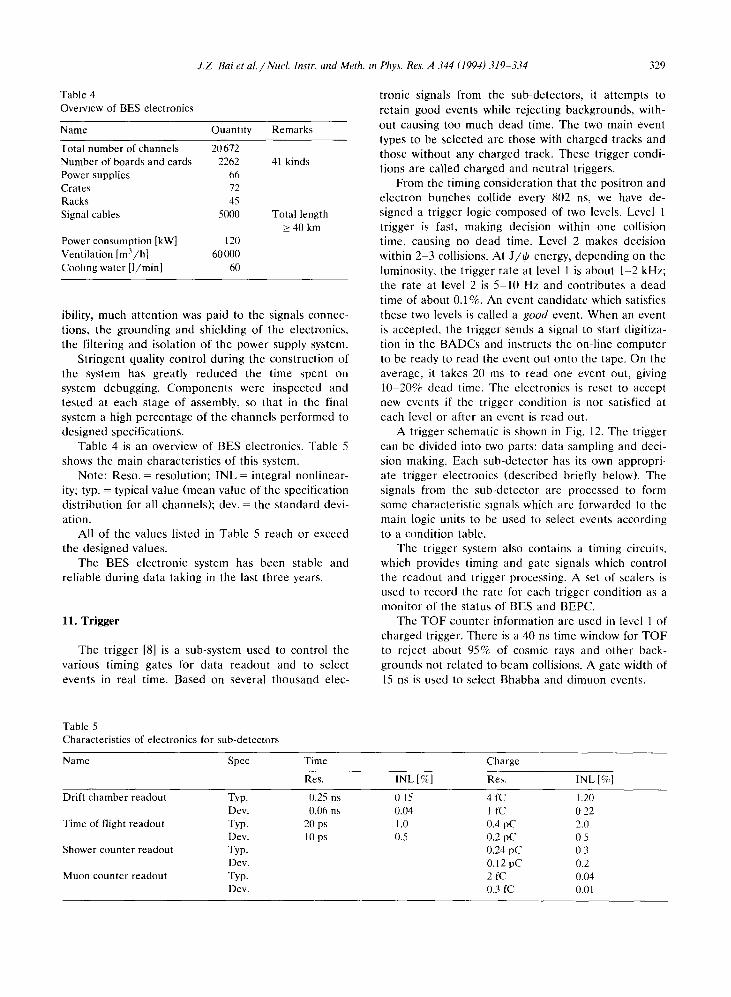
Table 4 is an overview of BES electronics . Table 5shows the main characteristics of this system .
Note : Reso . = resolution ; INL = integral nonlinear-ity ; typ. = typical value (mean value of the specificationdistribution for all channels); dev. = the standard devi-ation .
All of the values listed in Table 5 reach or exceedthe designed values .
The BES electronic system has been stable andreliable during data taking in the last three years.
11 . Trigger
The trigger [8] is a sub-system used to control thevarious timing gates for data readout and to selectevents in real time . Based on several thousand elec-
Table 5Characteristics of electronics for sub-detectors
tronic signals from the sub-detectors, it attempts toretain good events while rejecting backgrounds, with-out causing too much dead time . The two main eventtypes to be selected are those with charged tracks andthose without any charged track. These trigger condi-tions are called charged and neutral triggers .
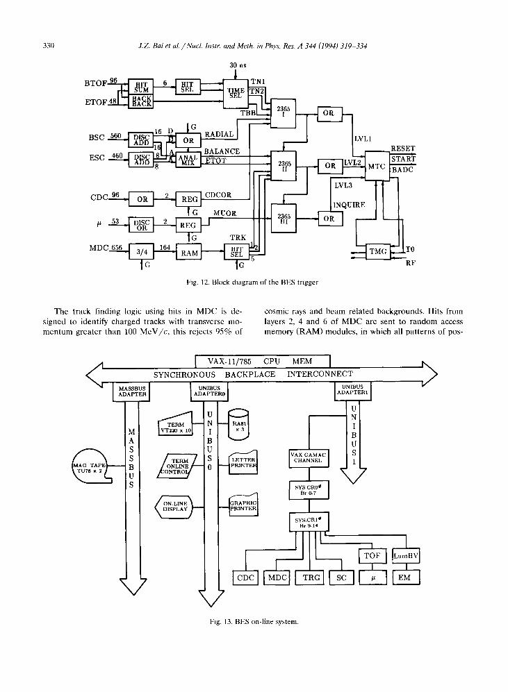
From the timing consideration that the positron andelectron bunches collide every 802 ns, we have de-signed a trigger logic composed of two levels. Level 1trigger is fast, making decision within one collisiontime, causing no dead time . Level 2 makes decisionwithin 2-3 collisions . At J/0 energy, depending on theluminosity, the trigger rate at level l is about 1-2 kHz;the rate at level 2 is 5-10 Hz and contributes a deadtime of about 0.1%. An event candidate which satisfiesthese two levels is called a good event. When an eventis accepted, the trigger sends a signal to start digitiza-tion in the BADCs and instructs the on-line computerto be ready to read the event out onto the tape . On theaverage, it takes 20 ms to read one event out, giving10-20% dead time . The electronics is reset to acceptnew events if the trigger condition is not satisfied ateach level or after an event is read out.A trigger schematic is shown in Fig. 12 . The trigger
can be divided into two parts: data sampling and deci-sion making . Each sub-detector has its own appropri-ate trigger electronics (described briefly below) . Thesignals from the sub-detector arc processed to formsome characteristic signals which arc forwarded to themain logic units to be used to select events accordingto a condition table.
The trigger system also contains a timing circuits,which provides timing and gate signals which controlthe readout and trigger processing . A set of sealers isused to record the rate for each trigger condition as amonitor of the status of BES and BEPC .
The TOF counter information are used in level 1 ofcharged trigger . There is a 40 ns time window for TOFto reject about 95% of cosmic rays and other back-grounds not related to beam collisions . A gate width of15 ns is used to select Bhabha and dimuon events .
329
Name Spec TimeRes. INL [%]
ChargeRes. INL [%]
Drift chamber readout Typ. 0 .25 ns 0 15 4 fC 1 .20Dev. 0.06 ns 0.04 1 fC 022
Time of flight readout Typ . 20 ps 1 .0 0 .4 pC 2 .0Dev. 10 ps 0.5 0 .2 pC 0 5
Shower counter readout Typ. 0 .24 pC 0 3Dev. 0.12 pC 0 .2
Muon counter readout Typ. 2 fC 0 .04Dev. 0.3 fC 0 .01
Table 4Overview of BES electronics
Name Quantity RemarksTotal number of channels 20672Number of boards and cards 2262 41 kindsPower supplies 66Crates 72Racks 45Signal cables 5000 Total length
>- 40 kmPower consumption [kW] 120Ventilation [m'/h] 60000Cooling water [1/min] 60
330
BTOF 9
J.Z . Bai et al. /Nucl. Instr. and Meth . in Phys . Res . A 344 (1994) 319-334
30 ns
r SÛM WITSIELE
The track finding logic using hits in MDC is de-signed to identify charged tracks with transverse mo-mentum greater than 100 MeV/c, this rejects 95% of
TN1
Fig . 12 . Block diagram of the BES trigger
Fig . 13 . BES on-line system .
TO
RF
cosmic rays and beam related backgrounds . Hits fromlayers 2, 4 and 6 of MDC are sent to random accessmemory (RAM) modules, in which all patterns of pos-
ETOF 48 BA~K 09M%r
2365
BSC 560 ADD16 D
03 ~RAREESC 460
DAD "c\ MIXL
CDC 96 OR REG CDCOR
MUOR J53ÖRC REG
TRKMDC 656 3/4 164
RAM SEL 5
12. Data acquisition system
J.Z. Bai et al. /Nnel. Instr. and Meth. to Phys . Res. A 344 (1994) 319-334
sible cell configurations of good tracks are stored . Agood track is flagged if one of the hit patterns issatisfied . The number of good tracks in an event isobtained from coincidence memory and a summingdiscriminator . This number is sent to main logic mod-ule. The track finding logic is in level 2 trigger sincethe maximum drift time in the MDC is more than 600ns which does not leave enough time for the necessaryprocessing before next beam crossing . The track con-figuration tables can be changed according to differentexperimental conditions .
There are six radial readout channels in the barrelshower counters . In the trigger the signals from twoadjacent cells are summed, the radial condition is satis-fied if one of the sums is greater than an adjustablethreshold . This condition is used to reject obliquecosmic rays and is used in the 1st level trigger . Furthersummation of these signals provides the total energy inthe BSC for each event. This signal of total energy inthe BSC is used in the second level trigger for rejectingbackgrounds due to the synchrotron radiation andbeam-gas scattering .
The CDC contributes to the second level triggerwith discriminated signals from the 96 cells of the thirdand fourth layers. The above signals are ORed by CDCdecision logic to pick out charged particles which hitCDC for rejecting various backgrounds that do notpass CDC. The condition is satisfied if there is a signalafter the OR logic .
Discriminated signals are formed from the hits inthe innermost layer of the muon counters, these signalsare ORed by muon trigger circuit to tag particles whichcan penetrate the shower counters and the magnetiron . This signal is only used for a special dimuontrigger .
The results from each of the sub-detector triggerlogic are transmitted to the main logic to make deci-sions according to a trigger condition table . Typicaltrigger requirements are: for a charged trigger, Not >_ 1(or Nof >_ 2) in level 1, Nrk >_ 1 (or Nlrk >2), the OR ofCDC and the total BSC energy >_ a low threshold inlevel 2; for a neutral trigger, the requirements are theradial condition in level 1, and the total BSC energy >_ ahigh threshold.
If the trigger conditions need to be adjusted orchanged, the new trigger condition table can be loadedto the main logic without changing any hardware con-figuration .
The on-line data acquisition system [9] is composedof a VAX 11/785 computer, a VCC (VAX-CAMAC-CHANNEL) interface and a CAMAC branch system,as shown in Fig. 13 . The computer has 6 MB memory,
33 1
three RA81 disk drives, two TU78 tape cartridgedrivers, an HP2686 laser printer and an LXY12 lineprinter for graphic outputs. Histograms can be dis-played on two color screens to be monitored by per-sons on shift .
Two system crates are linked by VCC to the com-puter. There are several branch receivers in the systemcrates, each of which can control up to seven CAMACbranches, so that an expandable multi-branch CAMACsystem is formed . In order to shorten the data trans-mission time, the readout sequence of the data in thesub-detectors is arranged according to their datalengths.A good running environment, including a set of
user-defined DCL commands and I/O file manage-ment has been set up . Data acquisition is initiatedsuccessfully for three kinds of interrupt sources: BESmain trigger events, luminosity monitor events andelectronics calibrations . Some data are displayed ac-cording to a scheduled timer. Data acquisition statusinformation and monitoring and error messages aredisplayed on terminal screens.When running the experiment, it is very important
for the on-line system to monitor working conditions ofthe sub-detectors and the electronics . Two kinds ofmonitoring are performed. In the first, simple distribu-tions of hit wires, time, pulse height and other indi-rectly measured quantities are made . For example,dual peak distribution of times in MDC cells, triggerchannel distribution, z distributions of hits in muoncounters and BSC, etc. These give important informa-tion on the status of the BES rapidly . In the secondmonitor, preliminary event sorting can be done . Forexample, Bhabha, dimuon, hadrons, cosmic rays andbeam-gas events are classified . The cross sections forprocesses of interest are calculated, histograms fordifferent classes of events are made . The two monitorsare active on about 25% of the data accumulated.
13 . Off-line analyses system
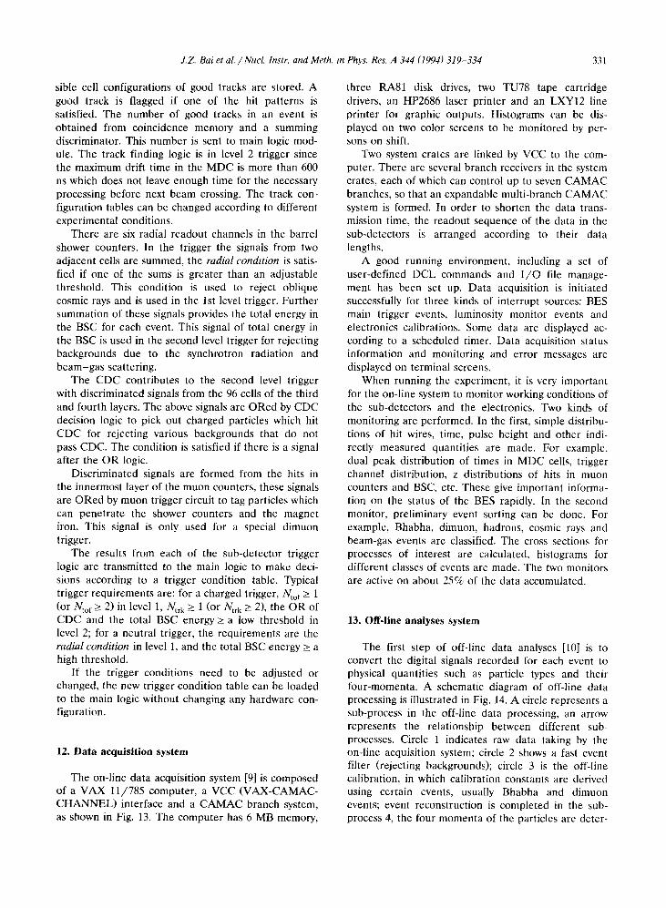
The first step of off-line data analyses [10] is toconvert the digital signals recorded for each event tophysical quantities such as particle types and theirfour-momenta . A schematic diagram of off-line dataprocessing is illustrated in Fig. 14 . A circle represents asub-process in the off-line data processing, an arrowrepresents the relationship between different sub-processes. Circle 1 indicates raw data taking by theon-line acquisition system ; circle 2 shows a fast eventfilter (rejecting backgrounds) ; circle 3 is the off-linecalibration, in which calibration constants are derivedusing certain events, usually Bhabha and dimuonevents ; event reconstruction is completed in the sub-process 4, the four momenta of the particles are deter-
332 J.Z. Bat et al. /Nuel. Instr. and Meth . to Phys. Res A 344 (1994) 319-334
1 Raw Data
2 Filtered Data
3 Calibration Constants
4 Post-filtered Data
5 Sorted Data
6 Physical Results
7 M. C. Data
Fig. 14 . Data flow chart of the BES off-line system .
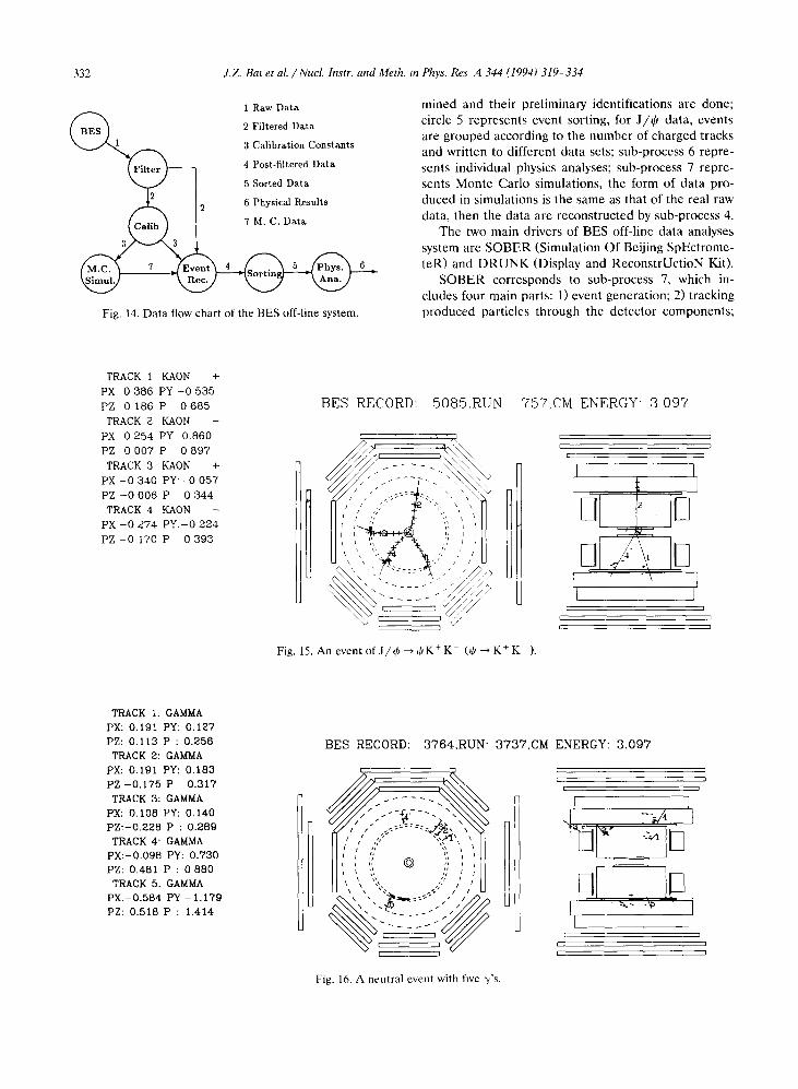
TRACK 1 KAON
+PX 0 386 PY -0 535PZ 0 186 P
0 685TRACK 2 KAON
-PX 0 254 PY 0.860PZ 0 007 P
0 897TRACK 3 KAON
+PX -0 340 PY -0 057PZ -0 006 P
0 344TRACK 4 KAON
-PX -0 274 PY.-0 224PZ -0 170 P
0 393
TRACK 1. GAMMAPX: 0 .191 PY : 0.127PZ : 0.113 P : 0.256TRACK 2: GAMMAPX : 0.191 PY : 0.183PZ -0.175 P
0.317TRACK 3: GAMMAPX : 0 .108 PY : 0.140PZ:-0.228 P : 0.269TRACK 4- GAMMAPX:-0.098 PY : 0.730PZ : 0.481 P : 0 880TRACK 5. GAMMAPX.-0.584 PY -1.179PZ : 0.518 P : 1 .414
mined and their preliminary identifications are done ;circle 5 represents event sorting, for J/tar data, eventsare grouped according to the number of charged tracksand written to different data sets ; sub-process 6 repre-sents individual physics analyses ; sub-process 7 repre-sents Monte Carlo simulations, the form of data pro-duced in simulations is the same as that of the real raw
data, then the data are reconstructed by sub-process 4.The two main drivers of BES off-line data analyses
system are SOBER (Simulation Of Beijing SpEctrome-teR) and DRUNK (Display and ReconstrUctioN Kit).SOBER corresponds to sub-process 7, which in-
cludes four main parts: 1) event generation ; 2) trackingproduced particles through the detector components ;
BES RECORD :
5085,RUN
757,CM ENERGY - 3 097
Fig. 16. A neutral event with five y's.
Fig. 15 . An event of J/(b - +(1K' K- (tP - K+ K- ).
BES RECORD : 3764,RUN - 3737,CM ENERGY : 3 .097
10
4
2
00
2
4
6
6 10
M2n + n o(GeV)2
3) detector response ; 4) signal digitization . In theframework of SOBER, multiple runs are allowed inone job, each run is specified by several parametersthrough control card records in a user generated file .In order to have some flexibility to deal with thevariation of detector conditions, the detector geometryand calibration constants are read from disk files .DRUNK contains six main parts: 1) pattern recog-
nition ; 2) local track and cluster fitting ; 3) matchingbetween detector components ; 4) particle identifica-tion ; 5) global fitting ; 6) event display . Input to DRUNKcan be real raw data, simulated data by SOBER, oralready reconstructed data . Output data may be fil-tered, reconstructed, or sorted data . DRUNK providesusers a simple, flexible interface to perform varioustasks such as event filter, sorting and physics analyses .
200
J.Z. Bat et al. /Nucl. Instr. and Meth . in Phys. Res. A 344 (1994) 319-334
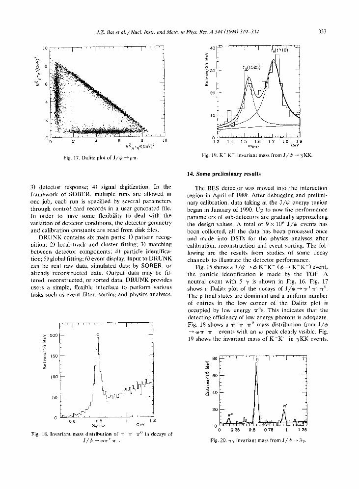
Fig. 17. Dalitz plot of J/iP --> pTr .
ai
Fig . 18 . Invariant mass distribution of "rr + lr - Tr ° in decays ofJ/0 -> w7r+7r-.
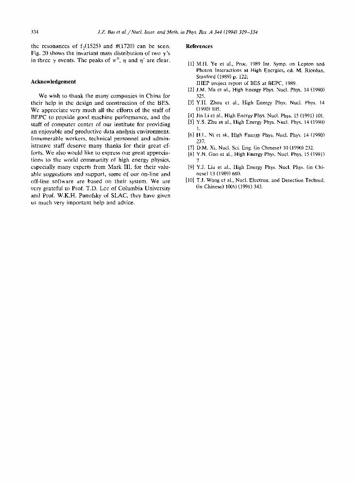
Fig . 19. K+K- invariant mass from J/d/ - yKK.
14 . Some preliminary results
The BES detector was moved into the interactionregion in April of 1989 . After debugging and prelimi-nary calibration, data taking at the J/0 energy regionbegan in January of 1990 . Up to now the performanceparameters of sub-detectors are gradually approachingthe design values . A total of 9 X 10⁶ J/0 events hasbeen collected, all the data has been processed onceand made into DSTs for the physics analyses aftercalibration, reconstruction and event sorting . The fol-lowing are the results from studies of some decaychannels to illustrate the detector performance .
Fig. 15 shows a J/ip - 0 K+K- (0 -> K+K-) event,the particle identification is made by the TOF. Aneutral event with 5 y is shown in Fig. 16 . Fig. 17shows a Dalitz plot of the decays of J/tP- ,rr + -rr-Tr ° .The p final states are dominant and a uniform numberof entries in the low corner of the Dalitz plot isoccupied by low energy rr ° s . This indicates that thedetecting efficiency of low energy photons is adequate .Fig. 18 shows a -rr +,R-Tr o mass distribution from J/0
c,)-rr +Tr- events with an W peak clearly visible . Fig.19 shows the invariant mass of K+K- in yKK events,
0 0 .25 0 .5 075 1 125
Fig . 20 . yy invariant mass from J/+f -> 3y .
333
0
md 150 80
cw
100 60
w1 Î 40
50 w
20
.06 08 1 12
Mn "� - � o GeV 0
334 J.Z. Bat et al. /Nucl. Instr. and Meth. in Phys. Res. A 344 (1994) 319-334
the resonances of f z(1525) and 9(1720) can be seen .Fig . 20 shows the invariant mass distribution of two y'sin three y events . The peaks of "rr ° , 71 and 77' are clear .
Acknowledgement
We wish to thank the many companies in China fortheir help in the design and construction of the BES .We appreciate very much all the efforts of the staff ofBEPC to provide good machine performance, and thestaff of computer center of our institute for providingan enjoyable and productive data analysis environment .Innumerable workers, technical personnel and admin-istrative staff deserve many thanks for their great ef-forts . We also would like to express our great apprecia-tions to the world community of high energy physics,especially many experts from Mark 111, for their valu-able suggestions and support, some of our on-line andoff-line software are based on their system . We arevery grateful to Prof. T.D . Lee of Columbia Universityand Prof. W.K.H . Panofsky of SLAC, they have givenus much very important help and advice .
References
[11 M.H . Ye et al ., Proc. 1989 Int . Symp . on Lepton andPhoton Interactions at High Energies, ed . M . Riordan,Stanford (1989) p . 122 ;IHEP project report of BES at BEPC, 1989 .
[21 J.M . Ma et al ., High Energy Phys . Nucl. Phys. 14 (1990)325 .
[31 Y.H. Zhou et al., High Energy Phys . Nucl . Phys . 14(1990) 105 .
[41 Jin Li et al ., High Energy Phys. Nucl . Phys. 15 (1991) 101 .[51 Y.S . Zhu et al ., High Energy Phys . Nucl . Phys . 14 (1990)
1 .[61 H.L . Ni et al ., High Energy Phys . Nucl . Phys . 14 (1990)
237 .[71 D.M . Xi, Nucl . Sci . Eng. (in Chinese) 10 (1990) 232 .[81 Y.N. Guo et al ., High Energy Phys . Nucl . Phys . 15 (1991)
7 .[91 Y.J . Liu et al ., High Energy Phys . Nucl . Phys. (in Chi-
nese) 13 (1989) 680 .[101 T .J . Wang et al ., Nucl . Electron . and Detection Technol .
(in Chinese) 10(6) (1991) 343 .


