Embed Size (px)
Citation preview
JOM • August 200650
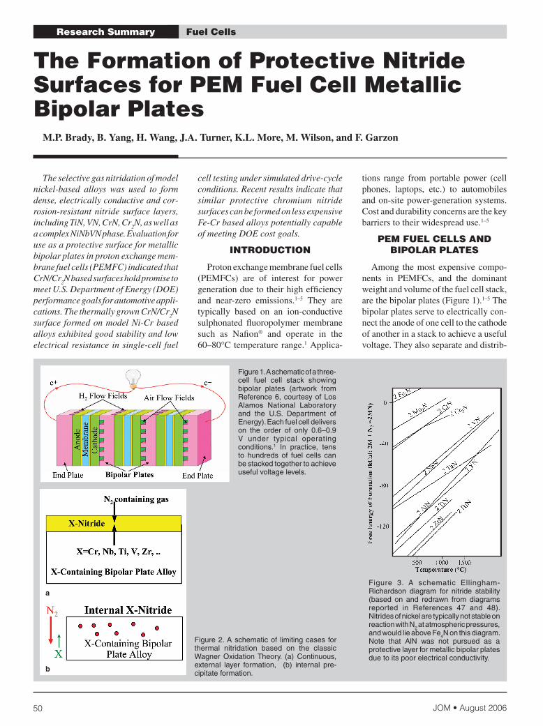
Figure 2. A schematic of limiting cases for thermal nitridation based on the classic Wagner Oxidation Theory. (a) Continuous, external layer formation, (b) internal pre-cipitate formation.
a
b
Fuel CellsResearch Summary
The Formation of Protective Nitride Surfaces for PEM Fuel Cell Metallic Bipolar Plates
M.P. Brady, B. Yang, H. Wang, J.A. Turner, K.L. More, M. Wilson, and F. Garzon
Figure 1. A schematic of a three-cell fuel cell stack showing bipolar plates (artwork from Reference 6, courtesy of Los Alamos National Laboratory and the U.S. Department of Energy). Each fuel cell delivers on the order of only 0.6–0.9 V under typical operating conditions.1 In practice, tens to hundreds of fuel cells can be stacked together to achieve useful voltage levels.
Figure 3. A schematic Ellingham-Richardson diagram for nitride stability (based on and redrawn from diagrams reported in References 47 and 48). Nitrides of nickel are typically not stable on reaction with N2 at atmospheric pressures, and would lie above Fe4N on this diagram. Note that AlN was not pursued as a protective layer for metallic bipolar plates due to its poor electrical conductivity.
Theselectivegasnitridationofmodelnickel-based alloys was used to formdense,electricallyconductiveandcor-rosion-resistantnitridesurface layers,includingTiN,VN,CrN,Cr
2N,aswellas
acomplexNiNbVNphase.Evaluationforuseasaprotectivesurfaceformetallicbipolarplatesinprotonexchangemem-branefuelcells(PEMFC)indicatedthatCrN/Cr
2Nbasedsurfacesholdpromiseto
meetU.S.DepartmentofEnergy(DOE)performancegoalsforautomotiveappli-cations.ThethermallygrownCrN/Cr
2N
surfaceformedonmodelNi-Crbasedalloysexhibitedgoodstabilityandlowelectricalresistanceinsingle-cell fuel
celltestingundersimulateddrive-cycleconditions.Recentresultsindicatethatsimilar protective chromium nitridesurfacescanbeformedonlessexpensiveFe-CrbasedalloyspotentiallycapableofmeetingDOEcostgoals.
INTRoduCTIoN
Protonexchangemembranefuelcells(PEMFCs) are of interest for powergenerationduetotheirhighefficiencyand near-zero emissions.1–5 They aretypically based on an ion-conductivesulphonated fluoropolymer membranesuch as Nafion® and operate in the60–80°Ctemperaturerange.1Applica-
tions range from portable power (cellphones, laptops, etc.) to automobilesandon-sitepower-generationsystems.Costanddurabilityconcernsarethekeybarrierstotheirwidespreaduse.1–5
PEM FuEl CEllS aNd BIPolaR PlaTES
Among themostexpensivecompo-nents in PEMFCs, and the dominantweightandvolumeofthefuelcellstack,arethebipolarplates(Figure1).1–5Thebipolarplatesservetoelectricallycon-necttheanodeofonecelltothecathodeofanotherinastacktoachieveausefulvoltage.Theyalsoseparateanddistrib-
2006 August • JOM 51
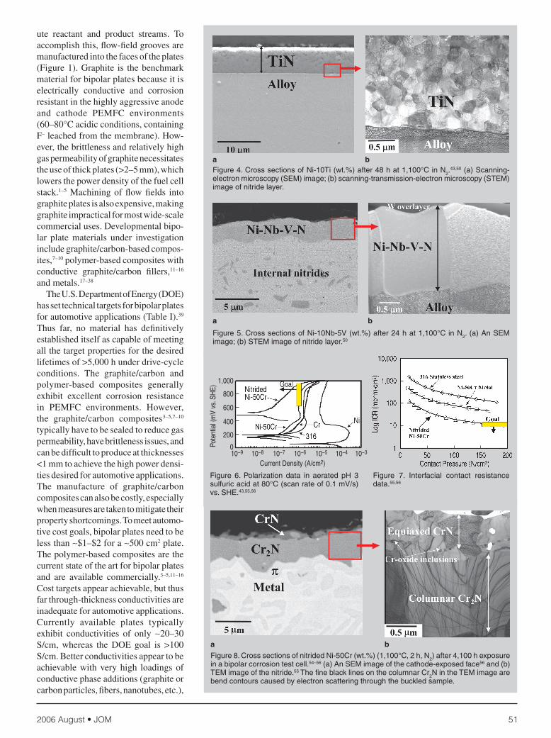
Figure 4. Cross sections of Ni-10Ti (wt.%) after 48 h at 1,100°C in N2.43,50 (a) Scanning-
electron microscopy (SEM) image; (b) scanning-transmission-electron microscopy (STEM) image of nitride layer.
a b
a b
Figure 5. Cross sections of Ni-10Nb-5V (wt.%) after 24 h at 1,100°C in N2. (a) An SEM image; (b) STEM image of nitride layer.50
Figure 6. Polarization data in aerated pH 3 sulfuric acid at 80°C (scan rate of 0.1 mV/s) vs. SHE.43,55,56
800
600
400
200
0
1,000
10−9 10−8 10−7 10−6 10−5 10−4 10−3
Current Density (A/cm2)
Pote
ntia
l (m
V vs
. SH
E)
a bFigure 8. Cross sections of nitrided Ni-50Cr (wt.%) (1,100°C, 2 h, N2) after 4,100 h exposure in a bipolar corrosion test cell.54–56 (a) An SEM image of the cathode-exposed face56 and (b) TEM image of the nitride.55 The fine black lines on the columnar Cr2N in the TEM image are bend contours caused by electron scattering through the buckled sample.
Figure 7. Interfacial contact resistance data.55,56
ute reactant and product streams. Toaccomplishthis,flow-fieldgroovesaremanufacturedintothefacesoftheplates(Figure1).Graphite is thebenchmarkmaterialforbipolarplatesbecauseitiselectrically conductive and corrosionresistantinthehighlyaggressiveanodeand cathode PEMFC environments(60–80°Cacidicconditions,containingF–leachedfromthemembrane).How-ever,thebrittlenessandrelativelyhighgaspermeabilityofgraphitenecessitatestheuseofthickplates(>2–5mm),whichlowersthepowerdensityofthefuelcellstack.1–5Machiningofflowfields intographiteplatesisalsoexpensive,makinggraphiteimpracticalformostwide-scalecommercialuses.Developmentalbipo-lar plate materials under investigationincludegraphite/carbon-basedcompos-ites,7–10polymer-basedcompositeswithconductive graphite/carbon fillers,11–16andmetals.17–38
TheU.S.DepartmentofEnergy(DOE)hassettechnicaltargetsforbipolarplatesforautomotiveapplications(TableI).39Thus far, no material has definitivelyestablisheditselfascapableofmeetingallthetargetpropertiesforthedesiredlifetimesof>5,000hunderdrive-cycleconditions. The graphite/carbon andpolymer-based composites generallyexhibit excellent corrosion resistancein PEMFC environments. However,the graphite/carbon composites3–5,7–10typicallyhavetobesealedtoreducegaspermeability,havebrittlenessissues,andcanbedifficulttoproduceatthicknesses<1mmtoachievethehighpowerdensi-tiesdesiredforautomotiveapplications.The manufacture of graphite/carboncompositescanalsobecostly,especiallywhenmeasuresaretakentomitigatetheirpropertyshortcomings.Tomeetautomo-tivecostgoals,bipolarplatesneedtobelessthan∼$1–$2fora∼500cm2plate.Thepolymer-basedcompositesarethecurrentstateoftheartforbipolarplatesand are available commercially.3–5,11–16Costtargetsappearachievable,butthusfarthrough-thicknessconductivitiesareinadequateforautomotiveapplications.Currently available plates typicallyexhibit conductivities of only ∼20–30S/cm, whereas the DOE goal is >100S/cm.Betterconductivitiesappeartobeachievablewithveryhigh loadingsofconductivephaseadditions(graphiteorcarbonparticles,fibers,nanotubes,etc.),
JOM • August 200652
TableI.DOETechnicalTargets:BipolarPlates39
Status
Characteristic Units 2004 2010
Cost $/kW 10 6Weight kg/kW 0.36 <1H
2PermeationFlux cm3sec–1cm–2@80°C, <2×10⁻⁶ <2×10⁻⁶
3atm(equivalentto<0.1mA/cm2)Corrosion μA/cm2 <1a <1b
ElectricalConductivity S/cm >600 >100Area-SpecificResistancec Ohmcm2 <0.02 0.01FlexuralStrength MPa >34 >4(crush)Flexibility %deflectionatmid-span 1.5to3.5 3to5
a–Basedoncoatedmetalplates;b–mayhavetobeaslowas1nA/cm2ifallcorrosionproductionsremaininionomer;c–includescontactresistance.
althoughthiscanmaketheplatesmoredifficulttomanufacture.Thehighload-ingsalsotendtomaketheplatesbrittle,especiallywhenmakingthinplatesontheorderof0.5mmto1mmthick.Despitetheircurrentlimitations,graphite/carbonand polymer-based composite bipolarplatesremainpromisingcandidates,andanumberofpublic andprivate sectordevelopmenteffortsarecurrentlyunderwaytoaddresstheirshortcomings. Seethesidebaronpage54fordetailsonmetallicbipolarplates.
ThERMally GRowN NITRIdE CoaTINGS
A possible solution to forming adefect-freeprotectivesurfaceonmetal-licbipolarplatesistogrowaprotectivenitridelayerfromthebipolarplatealloybyhigh-temperaturenitridation.43Tran-sitionmetalnitrides44offeranattractivecombinationofhighelectricalconductiv-ityandgoodcorrosionresistance,whichmakes them of interest for protectivecoatingsformetallicbipolarplates.2Inthermalnitridation,thegoalistodesignthealloyandsetthereactionconditionssuch that the desired nitride-formingelementdiffusesoutwardfromthealloytoreactwiththenitridinggastoformacontinuoussurfacelayer(Figure2a).Pin-holedefectsarenotanissuebecause,atelevatedtemperatures,thermodynamicandkineticfactorsfavorthereactionofallmetalsurfacesexposedtothenitridinggas.43Assuch,itisalsonotline-of-sightlimitedandisamenabletousewithcom-plex-shapedsurfacessuchastheedgesandcornersoftheflowfieldgroovesinbipolarplates(Figures1andA). Thedrawbackofthethermalnitrida-tionapproachisthatitisverysubstrate-alloydependentanditcanbedifficulttocontrolthecompositionandmorphology
ofthenitridethatisformed.Forexample,if thealloycompositionornitridationconditions are not selected properly,discrete internal nitride precipitates(Figure2b),whichwouldnotprovidecorrosionprotection,canforminsteadofthedesiredexternal,continuousnitridesurfacelayer(Figure2a).Further,evenifacontinuousnitridesurfacelayercanbe formed, cracking of the layer canoccur on cooling due to the thermalexpansionmismatchbetweenthenitrideandthesubstratealloy.Controlofsuchphenomena is the basis for protectiveoxidescaleformationbyheat-resistantalloys(e.g.,References45and46),buthasnotpreviouslybeenwellexploredasasynthesismethod to formprotec-tivenitridesurfacelayers.Theproposedthermalnitridationapproachisdifferentfromthemorefamiliarconventionalfer-rousalloynitridationtoachievesurfacehardening,wherebyconditionsaresettodiffusenitrogenextensivelyintothealloytoformironnitridesand/ornitro-gen-saturatediron-basedphasestenstohundredsofmicrometersdeep.Thegoalofbipolarplateprotectionistoformanexternal, continuous nitride layer nomorethanafewmicrometersthick. Exploratory work was performedwith the nitridation of model Ni-Xalloys, where X = Cr, Nb, Ti, V, andZrtoformCrN,Cr
2N,NbN,TiN,VN,
ZrN,etc.,phases.43Nickelwaschosenastheinitialalloybasebecauseitdoesnotformastablenitrideundertypicalnitridationconditions(Figure3)andhasalowpermeabilitytonitrogen,which,based on classic Wagner OxidationTheory (reviewed in References 45,46,and49), favors theformationofacontinuous, external nitride layer onnitridationratherthandiscreteinternalnitride precipitates (Figure 2). At the
timethisworkwasinitiated(2000),thecost of nickel was also relatively low(∼$2–3/lb),andpotentiallyabletomeetDOEautomotivecostgoals. In recentyears,thepriceofnickelhassignificantlyincreased (∼$6–10/lb), leavingnickel-basedalloystooexpensiveforPEMFCbipolar plate automotive applications.However,theprimarypurposeofthesestudieswasproof-of-principleevaluationofthethermalnitridationapproach,andto identify which nitride compoundshadthemostpromiseforprotectioninPEMFCenvironments. Nitrideformationwasexploredinthetemperaturerangeof800–1,200°CinN
2
and N2-4H
2 environments, rather than
conventionalsurface-hardeningnitridingconditionsof∼500–600°CinNH
3,which
produces a highly effective nitrogenactivityandfavorsinternalpenetrationofnitrogen.SomerepresentativenitridedmicrostructuresareshowninFigures4and5.43,50Acontinuous,external∼10µmthicklayerofTiNwasreadilyformedon Ni-10Ti (wt.%) (Ni-12Ti [at.%])afterexposureat1,100°Cfor48hinN
2
(Figure4a).Themicrostructureconsistedofahighlyplanarnitride/alloyinterface,withsubmicrometer,equiaxedgrainsofTiNofcompositionTi-(45–50)N(at.%)(Figure 4b). Such a microstructure isindicativeofconditionsfavoringnitridenucleationovergrowth,andisconsistentwith the expected high driving forcefornucleationduetothehighthermo-dynamicstabilityofTi/TiNrelativetonickel (Figure 3). Detailed studies ofnitride formation in Ni-Ti alloys bySavvaetal.51indicatethatthetransitionfrominternal toexternalTiNinNi-Tialloysoccursattitaniumlevelsaslowas∼Ni-(1–2)Ti(wt.%)(1–2.5at.%Ti)at1,020°C. Attheoppositeendofthespectrum,acoarse-grained,columnarmicrostructure(Figure5)wasformedonNi-10Nb-5V(wt.%)(Ni-6.5Nb-6V[at.%])afterexpo-sureundersimilarconditions(1,100°C,24 h, N
2) to Ni-10Ti (wt.%).50 Both
continuousexternalnitridelayerforma-tionandinternalnitrideformationwereevident.EffortstoformanNbNlayeronbinaryNi-Nballoyswerenotsuccessful,with very little reaction with nitrogenobserved.Additionsofvanadiumweremadeinanattempttoincreasereactiv-itywithnitrogen,asNi-Valloysreadilyformed VN surface layers. Vanadium
2006 August • JOM 53
was also selected because VN is ofintermediate thermodynamic stabilitybetween nickel and NbN (Figure 3),via the so-called third-element effect,whereby ternaryadditionsof interme-diate stability can help promote theformationofaprotectivesurfacelayerat alloy concentrations lower than inthe corresponding binary alloys. (TheclassicexampleofthisphenomenonischromiumadditionstoNi-AlandFe-Alalloys,whichlowerthelevelofaluminumneededtoformaprotectiveAl
2O
3scale
onthermaloxidationrelativetobinaryNi-Al andFe-Al alloys; the third ele-ment effect is reviewed inReferences45and46).Interestingly,ratherthananNbNsurfacelayer,acomplexnitrideofcomposition Ni-(12–15)V-(15–20)Nb-(20–30)N(at.%)wasformedonnitridedNi-10Nb-5V(wt.%).50X-raydiffractionanalysisindicatedthatboththealloyandthecomplexnitridewereface-centeredcubic structures (Fm3-m), suggestingthat the Ni-Nb-V-N composition andcolumnar structure may be more theresultofasolid-solutiontypereactionpaththananexclusiveselectivenitrida-tionprocess. Thecorrosionresistanceofthenitridesurface layers was assessed by polar-izationinpH3sulfuricacidsolutionsat80°CtosimulatePEMFCoperatingconditions.43Corrosioncurrentdensitiesoflessthan1× 10–6A/cm2upto∼0.9Vvs.standardhydrogenelectrode(SHE)under aerated conditions (to simulatethecathode-sideenvironment)and–0.2to +0.1 V vs. SHE under H
2-purged
conditions(tosimulate theanode-sideenvironment) were considered suf-ficiently promising to warrant furtherinvestigation.RelativelylowcorrosioncurrentdensitieswereobservedfortheTiN surfaces formed on Ni-Ti basedalloys, but post-test analysis revealedlocalareasofthrough-thicknessattackinsomecoupons.43Thisseemedtocor-relatewithTiNthickness,andwaslessprevalentwiththinnerTiNlayers(<1–2µm).TheVNandNi-Nb-V-Nsurfaceswerelesscorrosionresistantundertheseconditions,withcorrosioncurrentdensi-tiesinthe10–5to10–4A/cm2rangeat<0.9Vvs.SHEunderaeratedconditions.43Among the nitrided surfaces/nitridesevaluated,onlyCrN/Cr
2Nconsistently
exhibited the target corrosion currentdensities.43
PRoTECTIvE Cr-NITRIdE SuRFaCES oN ModEl Ni-Cr-BaSEd alloyS
Nitridation studies of binary Ni-Cralloys have indicated little reactivitywithnitrogenatlowlevelsofchromium;however, as the chromium level isincreased,nitrogenpermeability(whichfavorsinternalratherthanexternalnitrideformation) also increases,52 such thatlevelsofchromiuminexcessof∼30–35wt.%53,54areneededtoformanexternal,continuousnitride.Therefore,Ni-50Crwasusedasamodelmaterialtoevaluatethebehaviorofthermallygrownchro-mium-nitridesurfaces.PolarizationdatafornitridedNi-50Cr(1,100°C,2h,N
2)
inaeratedpH3sulfuricacidat80°CisshowninFigure6,andinterfacialcontactresistance(ICR)datainFigure7.43,55,56ThecorrosionresistanceofnitridedNi-50CrwassignificantlybetterthanthatofNi-50Crmetalandpurechromium,purenickel,andtype316stainlesssteel(∼18Cr-10Ni [wt.%] base) shown forcomparativepurposes.NitridationalsoloweredtheICRofNi-50Cr∼fivefold,totheDOEtargetvalueof10mohm-cm2atcontactpressuresof150–200N/cm2,which isanorderofmagnitude lowerthanthatof316stainlesssteel. Figure8showsthemicrostructureofnitridedNi-50Craftera4,100hexposureinabipolarcorrosiontestcellusingpH3sulfuricacidwith2ppmF–at80°C,withonecouponfaceexposedtoasolutionpurgedwithairandtheotherwithH
2.55
Thenitridedstructureconsistedofathin,equiaxedCrNlayeroverlyingadense,columnarCr
2Nlayer.Significantinternal
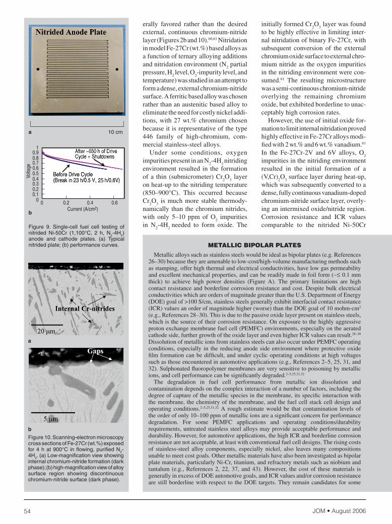
nitridationalsooccurred.Noattackofthenitridesurfacewasevident,despitethelong-termcorrosionexposure.TherewasalsonoincreaseinICRcomparedwiththeas-nitridedsurface. Basedonthesepromisingcorrosionand ICR screening results, single-cell fuel cell testing was pursued fornitridedNi-50Cr.A simple serpentine50 cm2 active area plate architecturewasadopted,usingthickNi-50Cranodeandcathodeplatesdesignedtoduplicategraphitetestplatehardware(Figure9a).Fullnitridesurfacecoveragewasreadilyachievedacrossalledge,corner,andflowfieldfeatures,withnoevidenceofCrN/Cr
2Nlayercrackingorlossofadherence.
Theseplateswereinitiallyrunfor500h
underconstant0.7Vconditions(80°C).Therewasnoplateresistanceincreaseorlossofperformance.Analysisofthemembraneelectrodeassembly (MEA)byx-rayfluorescence(XRF)indicatednometallicioncontaminationwithinthedetectionlimitsofthemeasurement,oftheorderof∼0.1–1×10⁻⁶g/cm2.Thisresult provides evidence that thermalnitridationcanprotectirregularsurfacefeaturessuchascorners,edges,holes,andflowfieldgrooves. ThenitridedNi-50Crplateswerethensubjectedtoanadditional∼1,160hofdrive-cycletestingusingacycleof0.94Vfor1min.,0.60Vfor30min.,0.70Vfor20min.,and0.50Vfor20min.Anadditional24fullshutdowns(cellcooledoff,gasesremoved,andopenedtoairatconnections)weresuperimposedinanattempttoinduceevenmoreaggressiveconditions.Nolossofperformancewasobserved;infact,performanceslightlyincreased during drive cycle testing(Figure9b).AsmallamountofnickelcontaminationoftheMEA,2×10–6g/cm2,was,however,detected.Thissmallamountofnickelwaslikelytheresultofleachingfromoccasional,localregionsoftheCrNiNπphase57–59thatwereini-tiallyformedduringnitridation,insteadof the more protective CrN/Cr
2N sur-
face.54NoattackoftheCrN/Cr2Nsurface
wasevident.(Suchlocalπphaseforma-tioncanoccuratregionsofsignificantchromium depletion in cast Ni-50Cr.)Overall,proof-of-principleexploratorycorrosion,ICR,andsingle-cellfuelcellstudiesindicatedthatthermallygrownCrN/Cr
2Nsurfacesshowgoodpotential
tomeetDOEbipolarplateperformanceanddurabilitygoals.
ExTENSIoN oF PRoTECTIvE Cr-NITRIdE
FoRMaTIoN To Fe-Cr-BaSEd alloyS
Withthecurrenthighcostofnickel(∼$6–10/lb),Ni-Crbasedalloyscannotmeet DOE automotive cost goals.Therefore,effortswereinitiatedtoformsimilarprotectiveCrN/Cr
2Nsurfaceson
Fe-Crbasedalloysbythermalnitridation.Thisisdifficultbecauseatcommerciallyviablelevelsofchromium,lessthan∼30wt.%chromiumduetotheσphasefield,the permeability of nitrogen in Fe-Cralloys issufficientlyhighthat internalchromium-nitrideprecipitatesaregen-
JOM • August 200654
10 cma
b
Figure 9. Single-cell fuel cell testing of nitrided Ni-50Cr (1,100°C, 2 h, N2-4H2) anode and cathode plates. (a) Typical nitrided plate; (b) performance curves. METallIC BIPolaR PlaTES
Metallicalloyssuchasstainlesssteelswouldbeidealasbipolarplates(e.g.References26–30)becausetheyareamenabletolow-cost/high-volumemanufacturingmethodssuchasstamping,offerhighthermalandelectricalconductivities,havelowgaspermeabilityandexcellentmechanicalproperties,andcanbereadilymadeinfoilform(∼≤0.1mmthick) to achieve high power densities (Figure A). The primary limitations are highcontactresistanceandborderlinecorrosionresistanceandcost.DespitebulkelectricalconductivitieswhichareordersofmagnitudegreaterthantheU.S.DepartmentofEnergy(DOE)goalof>100S/cm,stainlesssteelsgenerallyexhibitinterfacialcontactresistance(ICR)valuesanorderofmagnitudehigher(worse)thantheDOEgoalof10mohm-cm2(e.g.,References28–30).Thisisduetothepassiveoxidelayerpresentonstainlesssteels,whichisthesourceoftheircorrosionresistance.Onexposuretothehighlyaggressiveprotonexchangemembranefuelcell(PEMFC)environments,especiallyontheaeratedcathodeside,furthergrowthoftheoxidelayerandevenhigherICRvaluescanresult.28–30DissolutionofmetallicionsfromstainlesssteelscanalsooccurunderPEMFCoperatingconditions, especially in the reducinganode sideenvironmentwhereprotectiveoxidefilmformationcanbedifficult,andundercyclicoperatingconditionsathighvoltagessuchasthoseencounteredinautomotiveapplications(e.g.,References2–5,25,31,and32).Sulphonatedfluoropolymermembranesareverysensitivetopoisoningbymetallicions,andcellperformancecanbesignificantlydegraded.2–5,25,31,32
The degradation in fuel cell performance from metallic ion dissolution andcontaminationdependsonthecomplexinteractionofanumberoffactors,includingthedegreeofcaptureofthemetallicspeciesinthemembrane,itsspecificinteractionwiththemembrane,thechemistryofthemembrane,andthefuelcellstackcelldesignandoperating conditions.2–5,25,31,32 A rough estimate would be that contamination levels oftheorderofonly10–100ppmofmetallicionsareasignificantconcernforperformancedegradation. For some PEMFC applications and operating conditions/durabilityrequirements,untreatedstainlesssteelalloysmayprovideacceptableperformanceanddurability.However,forautomotiveapplications,thehighICRandborderlinecorrosionresistancearenotacceptable,atleastwithconventionalfuelcelldesigns.Therisingcostsof stainless-steel alloy components, especially nickel, also leaves many compositionsunabletomeetcostgoals.Othermetallicmaterialshavealsobeeninvestigatedasbipolarplatematerials,particularlyNi-Cr,titanium,andrefractorymetalssuchasniobiumandtantalum (e.g.,References2,22,37, and43).However, thecostof thesematerials isgenerallyinexcessofDOEautomotivegoals,andICRvaluesand/orcorrosionresistancearestillborderlinewithrespect to theDOEtargets.Theyremaincandidatesforsome
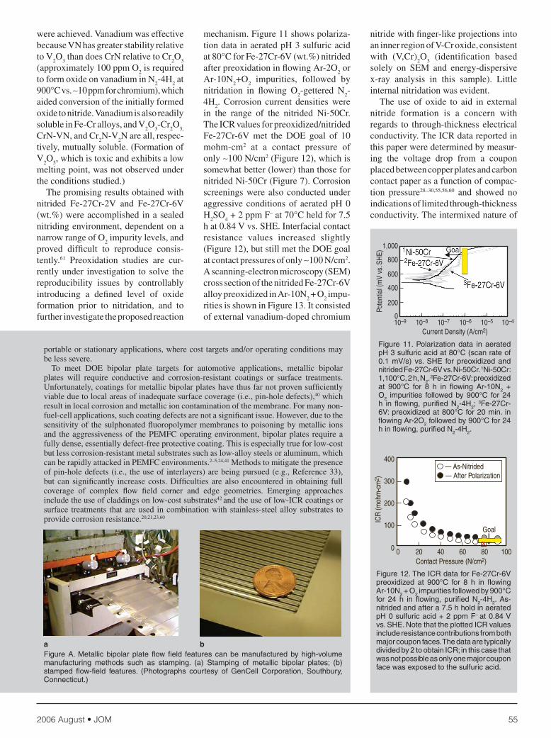
Figure 10. Scanning-electron microscopy cross sections of Fe-27Cr (wt.%) exposed for 4 h at 900°C in flowing, purified N2-4H2. (a) Low-magnification view showing internal chromium-nitride formation (dark phase); (b) high-magnification view of alloy surface region showing discontinuous chromium-nitride surface (dark phase).
b
a
erally favored rather than the desiredexternal,continuouschromium-nitridelayer(Figures2band10).60,61NitridationinmodelFe-27Cr(wt.%)basedalloysasafunctionofternaryalloyingadditionsandnitridationenvironment(N
2partial
pressure,H2level,O
2-impuritylevel,and
temperature)wasstudiedinanattempttoformadense,externalchromium-nitridesurface.Aferriticbasedalloywaschosenratherthananausteniticbasedalloytoeliminatetheneedforcostlynickeladdi-tions,with27wt.%chromiumchosenbecauseitisrepresentativeofthetype446 family of high-chromium, com-mercialstainless-steelalloys. Under some conditions, oxygenimpuritiespresentinanN
2-4H
2nitriding
environment resulted in the formationofa thin (submicrometer)Cr
2O
3 layer
onheat-uptothenitridingtemperature(850–900°C). This occurred becauseCr
2O
3 ismuchmore stable thermody-
namicallythanthechromiumnitrides,with only 5–10 ppm of O
2 impurities
in N2-4H
2needed to form oxide. The
initiallyformedCr2O
3layerwasfound
tobehighlyeffectiveinlimitinginter-nalnitridationofbinaryFe-27Cr,withsubsequent conversion of the externalchromiumoxidesurfacetoexternalchro-miumnitrideastheoxygenimpuritiesinthenitridingenvironmentwerecon-sumed.61 The resulting microstructurewasasemi-continuouschromium-nitrideoverlying the remaining chromiumoxide,butexhibitedborderlinetounac-ceptablyhighcorrosionrates. However,theuseofinitialoxidefor-mationtolimitinternalnitridationprovedhighlyeffectiveinFe-27Cralloysmodi-fiedwith2wt.%and6wt.%vanadium.61In the Fe-27Cr-2V and 6V alloys, O
2
impuritiesinthenitridingenvironmentresulted in the initial formation of a(V,Cr)
2O
3surfacelayerduringheat-up,
whichwassubsequentlyconvertedtoadense,fullycontinuousvanadium-dopedchromium-nitridesurfacelayer,overly-inganintermixedoxide/nitrideregion.Corrosion resistance and ICR valuescomparable to the nitrided Ni-50Cr
0.90.80.70.60.50.40.30.20.1
1
0 0 0.2 0.4 0.6Current (A/cm2)
Volta
ge
2006 August • JOM 55
Figure A. Metallic bipolar plate flow field features can be manufactured by high-volume manufacturing methods such as stamping. (a) Stamping of metallic bipolar plates; (b) stamped flow-field features. (Photographs courtesy of GenCell Corporation, Southbury, Connecticut.)
portableorstationaryapplications,wherecosttargetsand/oroperatingconditionsmaybelesssevere. To meet DOE bipolar plate targets for automotive applications, metallic bipolarplates will require conductive and corrosion-resistant coatings or surface treatments.Unfortunately,coatingsformetallicbipolarplateshavethusfarnotprovensufficientlyviableduetolocalareasofinadequatesurfacecoverage(i.e.,pin-holedefects),40whichresultinlocalcorrosionandmetallicioncontaminationofthemembrane.Formanynon-fuel-cellapplications,suchcoatingdefectsarenotasignificantissue.However,duetothesensitivityofthesulphonatedfluoropolymermembranestopoisoningbymetallicionsand theaggressivenessof thePEMFCoperatingenvironment,bipolarplates requireafullydense,essentiallydefect-freeprotectivecoating.Thisisespeciallytrueforlow-costbutlesscorrosion-resistantmetalsubstratessuchaslow-alloysteelsoraluminum,whichcanberapidlyattackedinPEMFCenvironments.2–5,24,41Methodstomitigatethepresenceofpin-holedefects(i.e.,theuseofinterlayers)arebeingpursued(e.g.,Reference33),but can significantly increasecosts.Difficultiesarealsoencountered inobtaining fullcoverage of complex flow field corner and edge geometries. Emerging approachesincludetheuseofcladdingsonlow-costsubstrates42andtheuseoflow-ICRcoatingsorsurface treatments thatareused incombinationwithstainless-steelalloysubstrates toprovidecorrosionresistance.20,21,23,60
a b
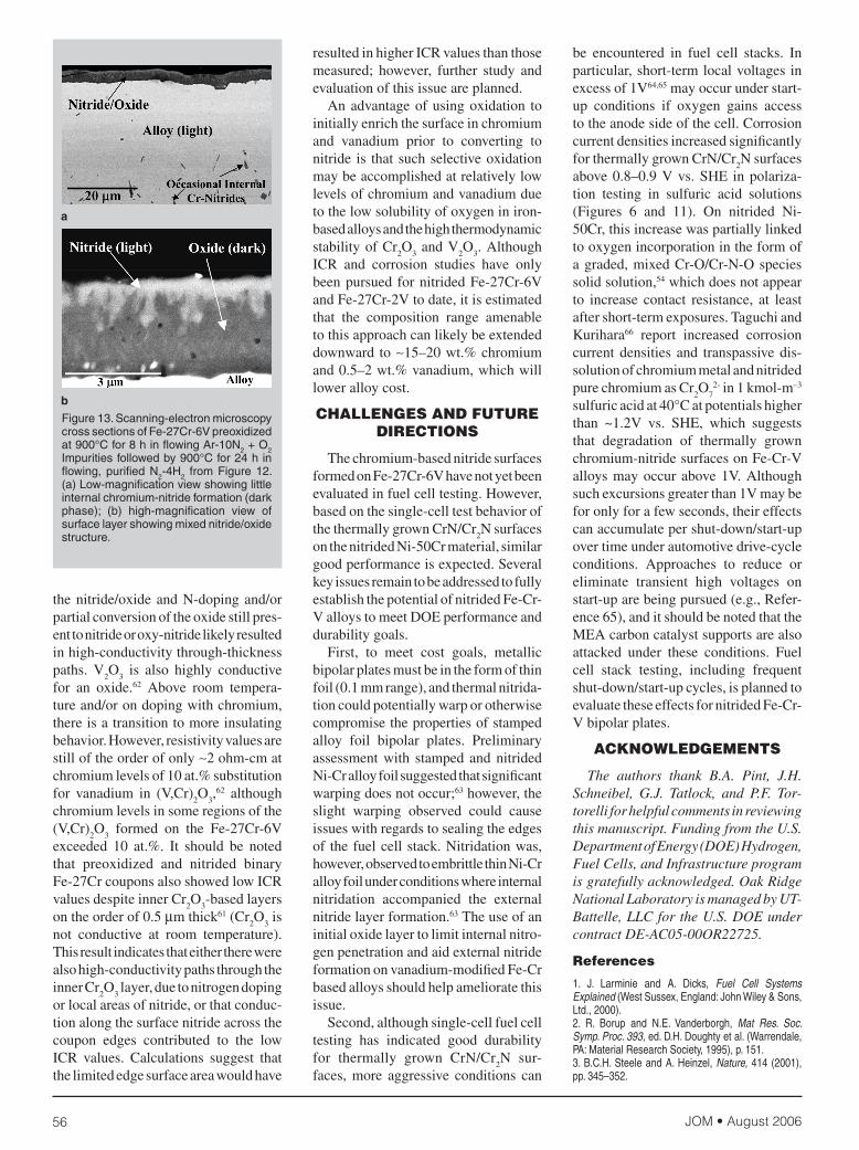
Figure 12. The ICR data for Fe-27Cr-6V preoxidized at 900°C for 8 h in flowing Ar-10N2 + O2 impurities followed by 900°C for 24 h in flowing, purified N2-4H2. As-nitrided and after a 7.5 h hold in aerated pH 0 sulfuric acid + 2 ppm F.– at 0.84 V vs. SHE. Note that the plotted ICR values include resistance contributions from both major coupon faces. The data are typically divided by 2 to obtain ICR; in this case that was not possible as only one major coupon face was exposed to the sulfuric acid.
800
600
400
200
0
1,000
10−9 10−8 10−7 10−6 10−5 10−4
Current Density (A/cm2)
Pote
ntia
l (m
V vs
. SH
E)
Figure 11. Polarization data in aerated pH 3 sulfuric acid at 80°C (scan rate of 0.1 mV/s) vs. SHE for preoxidized and nitrided Fe-27Cr-6V vs. Ni-50Cr. 1Ni-50Cr: 1,100°C, 2 h, N2.
2Fe-27Cr-6V: preoxidized at 900°C for 8 h in flowing Ar-10N2 + O2 impurities followed by 900°C for 24 h in flowing, purified N2-4H2;
3Fe-27Cr-6V: preoxidized at 800°C for 20 min. in flowing Ar-2O2 followed by 900°C for 24 h in flowing, purified N2-4H2.
wereachieved.VanadiumwaseffectivebecauseVNhasgreaterstabilityrelativetoV
2O
3thandoesCrNrelativetoCr
2O
3
(approximately100ppmO2isrequired
toformoxideonvanadiuminN2-4H
2at
900°Cvs.∼10ppmforchromium),whichaidedconversionoftheinitiallyformedoxidetonitride.VanadiumisalsoreadilysolubleinFe-Cralloys,andV
2O
3-Cr
2O
3,
CrN-VN,andCr2N-V
2Nareall,respec-
tively,mutuallysoluble.(FormationofV
2O
5,whichistoxicandexhibitsalow
meltingpoint,wasnotobservedundertheconditionsstudied.)
Thepromisingresultsobtainedwithnitrided Fe-27Cr-2V and Fe-27Cr-6V(wt.%)wereaccomplishedinasealednitridingenvironment,dependentonanarrowrangeofO
2impuritylevels,and
proved difficult to reproduce consis-tently.61 Preoxidation studies are cur-rentlyunder investigation tosolve thereproducibility issues by controllablyintroducing a defined level of oxideformation prior to nitridation, and tofurtherinvestigatetheproposedreaction
mechanism.Figure11showspolariza-tiondatainaeratedpH3sulfuricacidat80°CforFe-27Cr-6V(wt.%)nitridedafterpreoxidationinflowingAr-2O
2or
Ar-10N2+O
2 impurities, followed by
nitridation in flowing O2-gettered N
2-
4H2. Corrosion current densities were
in the range of the nitrided Ni-50Cr.TheICRvaluesforpreoxidized/nitridedFe-27Cr-6V met the DOE goal of 10mohm-cm2 at a contact pressure ofonly∼100N/cm2(Figure12),whichissomewhatbetter(lower)thanthosefornitridedNi-50Cr(Figure7).CorrosionscreeningswerealsoconductedunderaggressiveconditionsofaeratedpH0H
2SO
4+2ppmF–at70°Cheldfor7.5
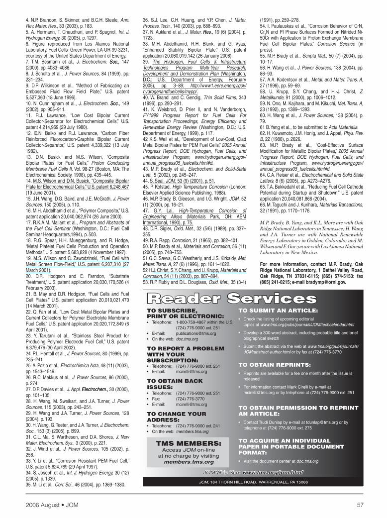
hat0.84Vvs.SHE.Interfacialcontactresistance values increased slightly(Figure12),butstillmettheDOEgoalatcontactpressuresofonly∼100N/cm2.Ascanning-electronmicroscopy(SEM)crosssectionofthenitridedFe-27Cr-6ValloypreoxidizedinAr-10N
2+O
2impu-
ritiesisshowninFigure13.Itconsistedofexternalvanadium-dopedchromium
nitridewithfinger-likeprojectionsintoaninnerregionofV-Croxide,consistentwith (V,Cr)
2O
3 (identification based
solely on SEM and energy-dispersivex-ray analysis in this sample). Littleinternalnitridationwasevident. The use of oxide to aid in externalnitride formation is a concern withregards to through-thicknesselectricalconductivity.TheICRdatareportedinthispaperweredeterminedbymeasur-ing the voltage drop from a couponplacedbetweencopperplatesandcarboncontactpaperasafunctionofcompac-tion pressure28–30,55,56,60 and showed noindicationsoflimitedthrough-thicknessconductivity.Theintermixednatureof
400
300
200
100
0 0 20 40Contact Pressure (N/cm2)
ICR
(moh
m-c
m2 )
60 100
— As-Nitrided� — After Polarization
Goal�
�
�
�
�� � � � � �
� � ��������
�
�
� �
80xx
JOM • August 200656
Figure 13. Scanning-electron microscopy cross sections of Fe-27Cr-6V preoxidized at 900°C for 8 h in flowing Ar-10N2 + O2 Impurities followed by 900°C for 24 h in flowing, purified N2-4H2 from Figure 12. (a) Low-magnification view showing little internal chromium-nitride formation (dark phase); (b) high-magnification view of surface layer showing mixed nitride/oxide structure.
b
a
thenitride/oxideandN-dopingand/orpartialconversionoftheoxidestillpres-enttonitrideoroxy-nitridelikelyresultedinhigh-conductivitythrough-thicknesspaths. V
2O
3 is also highly conductive
for an oxide.62 Above room tempera-tureand/orondopingwithchromium,thereisatransitiontomoreinsulatingbehavior.However,resistivityvaluesarestilloftheorderofonly∼2ohm-cmatchromiumlevelsof10at.%substitutionfor vanadium in (V,Cr)
2O
3,62 although
chromiumlevelsinsomeregionsofthe(V,Cr)
2O
3 formed on the Fe-27Cr-6V
exceeded 10 at.%. It should be notedthat preoxidized and nitrided binaryFe-27CrcouponsalsoshowedlowICRvaluesdespiteinnerCr
2O
3-basedlayers
ontheorderof0.5µmthick61(Cr2O
3is
not conductive at room temperature).Thisresultindicatesthateithertherewerealsohigh-conductivitypathsthroughtheinnerCr
2O
3layer,duetonitrogendoping
orlocalareasofnitride,orthatconduc-tionalongthesurfacenitrideacrossthecoupon edges contributed to the lowICR values. Calculations suggest thatthelimitededgesurfaceareawouldhave
resultedinhigherICRvaluesthanthosemeasured; however, further study andevaluationofthisissueareplanned. Anadvantageofusingoxidation toinitiallyenrichthesurfaceinchromiumand vanadium prior to converting tonitride is thatsuchselectiveoxidationmaybeaccomplishedatrelativelylowlevelsofchromiumandvanadiumduetothelowsolubilityofoxygeniniron-basedalloysandthehighthermodynamicstabilityofCr
2O
3andV
2O
3.Although
ICR and corrosion studies have onlybeenpursuedfornitridedFe-27Cr-6VandFe-27Cr-2Vtodate,itisestimatedthat the composition range amenabletothisapproachcanlikelybeextendeddownward to∼15–20wt.%chromiumand0.5–2wt.%vanadium,whichwillloweralloycost.
ChallENGES aNd FuTuRE dIRECTIoNS
Thechromium-basednitridesurfacesformedonFe-27Cr-6Vhavenotyetbeenevaluatedinfuelcelltesting.However,basedonthesingle-celltestbehaviorofthethermallygrownCrN/Cr
2Nsurfaces
onthenitridedNi-50Crmaterial,similargoodperformanceisexpected.SeveralkeyissuesremaintobeaddressedtofullyestablishthepotentialofnitridedFe-Cr-ValloystomeetDOEperformanceanddurabilitygoals. First, to meet cost goals, metallicbipolarplatesmustbeintheformofthinfoil(0.1mmrange),andthermalnitrida-tioncouldpotentiallywarporotherwisecompromisethepropertiesofstampedalloy foil bipolar plates. Preliminaryassessmentwith stamped andnitridedNi-Cralloyfoilsuggestedthatsignificantwarpingdoesnotoccur;63however,theslight warping observed could causeissueswithregardstosealingtheedgesof thefuelcellstack.Nitridationwas,however,observedtoembrittlethinNi-Cralloyfoilunderconditionswhereinternalnitridation accompanied the externalnitridelayerformation.63Theuseofaninitialoxidelayertolimitinternalnitro-genpenetrationandaidexternalnitrideformationonvanadium-modifiedFe-Crbasedalloysshouldhelpamelioratethisissue. Second,althoughsingle-cellfuelcelltesting has indicated good durabilityfor thermally grown CrN/Cr
2N sur-
faces, more aggressive conditions can
be encountered in fuel cell stacks. Inparticular,short-termlocalvoltagesinexcessof1V64,65mayoccurunderstart-up conditions if oxygen gains accesstotheanodesideofthecell.CorrosioncurrentdensitiesincreasedsignificantlyforthermallygrownCrN/Cr
2Nsurfaces
above0.8–0.9Vvs.SHE inpolariza-tion testing in sulfuric acid solutions(Figures 6 and 11). On nitrided Ni-50Cr,thisincreasewaspartiallylinkedtooxygenincorporationintheformofagraded,mixedCr-O/Cr-N-Ospeciessolidsolution,54whichdoesnotappearto increase contact resistance, at leastaftershort-termexposures.TaguchiandKurihara66 report increased corrosioncurrentdensities and transpassivedis-solutionofchromiummetalandnitridedpurechromiumasCr
2O
72-in1kmol-m–3
sulfuricacidat40°Catpotentialshigherthan ~1.2V vs. SHE, which suggeststhat degradation of thermally grownchromium-nitridesurfacesonFe-Cr-Valloysmayoccurabove1V.Althoughsuchexcursionsgreaterthan1Vmaybeforonlyforafewseconds,theireffectscanaccumulatepershut-down/start-upovertimeunderautomotivedrive-cycleconditions. Approaches to reduce oreliminate transient high voltages onstart-uparebeingpursued(e.g.,Refer-ence65),anditshouldbenotedthattheMEAcarboncatalystsupportsarealsoattacked under these conditions. Fuelcell stack testing, including frequentshut-down/start-upcycles,isplannedtoevaluatetheseeffectsfornitridedFe-Cr-Vbipolarplates.
aCkNowlEdGEMENTS
The authors thank B.A. Pint, J.H.Schneibel, G.J. Tatlock, and P.F. Tor-torelliforhelpfulcommentsinreviewingthismanuscript.FundingfromtheU.S.DepartmentofEnergy(DOE)Hydrogen,FuelCells,andInfrastructureprogramisgratefullyacknowledged.OakRidgeNationalLaboratoryismanagedbyUT-Battelle,LLCfortheU.S.DOEundercontractDE-AC05-00OR22725.
References
1. J. Larminie and A. Dicks, Fuel Cell Systems Explained (West Sussex, England: John Wiley & Sons, Ltd., 2000). 2. R. Borup and N.E. Vanderborgh, Mat Res. Soc. Symp. Proc. 393, ed. D.H. Doughty et al. (Warrendale, PA: Material Research Society, 1995), p. 151.3. B.C.H. Steele and A. Heinzel, Nature, 414 (2001), pp. 345–352.
2006 August • JOM 57
4. N.P. Brandon, S. Skinner, and B.C.H. Steele, Ann. Rev. Mater. Res., 33 (2003), p. 183. 5. A. Hermann, T. Chaudhuri, and P. Spagnol, Int. J. Hydrogen Energy, 30 (2005), p. 1297. 6. Figure reproduced from Los Alamos National Laboratory, Fuel Cells–Green Power, LA-UR-99-3231, courtesy of the United States Department of Energy.7. T.M. Besmann et al., J. Electrochem. Soc.,Soc., 147 (2000), pp. 4083–4086. 8. J. Scholta et al., J. Power Sources, 84 (1999), pp. 231–234.9. D.P. Wilkinson et al., “Method of Fabricating an Embossed Fluid Flow Field Plate,” U.S. patent 5,527,363 (18 June 1996).10. N. Cunningham et al., J. Electrochem. Soc.,Soc., 149 (2002), pp. 905–911. 11. R.J. Lawrance, “Low Cost Bipolar Current Collector-Separator for Electrochemical Cells,” U.S. patent 4,214,969 (29 July 1980). 12. E.N. Balko and R.J. Lawrance, “Carbon Fiber Reinforced Fluorocarbon-Graphite Bipolar Current Collector-Separator,” U.S. patent 4,339,322 (13 July 1982).13. D.N. Busick and M.S. Wilson, “Composite Bipolar Plates for Fuel Cells,” Proton Conducting Membrane Fuel Cells II, Vol. 98-27 (Boston, MA: The Electrochemical Society, 1998), pp. 435–445.14. M.S. Wilson and D.N. Busick, “Composite Bipolar Plate for Electrochemical Cells,” U.S. patent 6,248,467 (19 June 2001).15. J.H. Wang, D.G. Baird, and J.E. McGrath, J. Power Sources, 150 (2005), p. 110. 16. M.H. Abdelhamid et al., “Polymer Composite,” U.S. patent application 20,040,062,974 (26 June 2003).17. R.K.A.M. Mallant et al., Program and Abstracts of the Fuel Cell Seminar (Washington, D.C.: Fuel Cell Seminar Headquarters,1994), p. 503.18. R.G. Spear, H.H. Mueggenburg, and R. Hodge, “Metal Platelet Fuel Cells Production and Operation Methods,” U.S. patent 5,683,828 (4 November 1997).19. M.S. Wilson and C. Zawodzinski, “Fuel Cell with Metal Screen Flow-Field,” U.S. patent 6,207,310 (27 March 2001).20. D.R. Hodgson and E. Farndon, “Substrate Treatment,” U.S. patent application 20,030,170,526 (4 February 2003).21. B. May and D.R. Hodgson, “Fuel Cells and Fuel Cell Plates,” U.S. patent application 20,010,021,470 (14 March 2001).22. Q. Fan et al., “Low Cost Metal Bipolar Plates and Current Collectors for Polymer Electrolyte Membrane Fuel Cells,” U.S. patent application 20,020,172,849 (6 April 2001). 23. Y. Tarutani et al., “Stainless Steel Product for Producing Polymer Electrode Fuel Cell,” U.S. patent 6,379,476 (30 April 2002). 24. P.L. Hentall et al., J. Power Sources, 80 (1999), pp. 235–241.25. A. Pozio et al., Electrochimica Acta, 48 (11) (2003), pp. 1543–1549.26. R.C. Makkus et al., J. Power Sources, 86 (2000), p. 274.27. D.P. Davies et al., J. Appl. Electrochem.,Electrochem., 30 (2000), pp. 101–105.28. H. Wang, M. Sweikart, and J.A. Turner, J. Power Sources, 115 (2003), pp. 243–251. 29. H. Wang and J.A. Turner, J. Power Sources, 128 (2004), p. 193. 30. H. Wang, G. Teeter, and J.A. Turner, J. Electrochem. Soc., 153 (3) (2005), p. B99. 31. C.L. Ma, S. Warthesen, and D.A. Shores, J. New Mater. Electrochem. Sys., 3 (2000), p. 221. 32. J. Wind et al., J. Power Sources, 105 (2002), p. 256. 33. Y. Li et al., “Corrosion Resistant PEM Fuel Cell,” U.S. patent 5,624,769 (29 April 1997).34. S. Joseph et al., Int. J. Hydrogen Energy, 30 (12) (2005), p. 1339.35. M. Li et al., Corr. Sci., 46 (2004), pp. 1369–1380.
36. S.J. Lee, C.H. Huang, and Y.P. Chen, J. Mater. Process. Tech., 140 (2003), pp. 688–693.37. N. Aukland et al., J. Mater. Res.,Res., 19 (6) (2004), p. 1723.38. M.H. Abdelhamid, R.H. Blunk, and G. Vyas, “Enhanced Stability Bipolar Plate,” U.S. patent application 20,060,019,142 (26 January 2006).39. The Hydrogen, Fuel Cells & Infrastructure Technologies Program Multi-Year Research, Development and Demonstration Plan (Washington, D.C.: U.S. Department of Energy, February 2005), pp. 3–89; http://www1.eere.energy.gov/hydrogenandfuelcells/mypp/.40. W. Brandl and C. Gendig, Thin Solid Films, 343 (1996), pp. 290–291. 41. K. Weisbrod, D. Prier II, and N. Vanderborgh, FY1999 Progress Report for Fuel Cells For Transportation Proceedings, Energy Efficiency and Renewable Energy Review (Washington, D.C.: U.S. Department of Energy, 1999), p. 117.42 K.S. Weil et al., “Development of Low-Cost, Clad Metal Bipolar Plates for PEM Fuel Cells,” 2005 Annual Progress Report, DOE Hydrogen, Fuel Cells, and Infrastructure Program, www.hydrogen.energy.gov/annual_progress05_fuelcells.html#d.43. M.P. Brady et al., Electrochem. and Solid-State Lett., 5 (2002), pp. 245–247. 44. S. Seal, JOM, 53 (9) (2001), p. 51. 45. P. Kofstad, High Temperature Corrosion (London: Elsevier Applied Science Publishing, 1988).46. M.P. Brady, B. Gleeson, and I.G. Wright, JOM, 52 (1) (2000), pp. 16–21.47. G.Y. Lai, High-Temperature Corrosion of Engineering Alloys (Materials Park, OH: ASM International, 1990), p. 75.48. D.R. Sigler, Oxid. Met., 32 (5/6) (1989), pp. 337–355.49. R.A. Rapp, Corrosion, 21 (1965), pp. 382–401.50. M.P. Brady et al., Materials and Corrosion, 56 (11) (2005), pp. 748–755. 51 G.C. Savva, G.C. Weatherly, and J.S. Kirkaldy, Met. Mater. Trans. A, 27 (6) (1996), pp. 1611–1622. 52 H.J. Christ, S.Y. Chang, and U. Krupp, Materials and Corrosion, 54 (11) (2003), pp. 887–894. 53. R.P. Rubly and D.L. Douglass, Oxid. Met., 35 (3-4)
(1991), pp. 259–278. 54. I. Paulauskas et al., “Corrosion Behavior of CrN, Cr2N and PI Phase Surfaces Formed on Nitrided Ni-50Cr with Application to Proton Exchange Membrane Fuel Cell Bipolar Plates,” Corrosion Science (in press). 55. M.P. Brady et al., Scripta Mat., 50 (7) (2004), pp. 10–17.56. H. Wang et al., J. Power Sources, 138 (2004), pp. 86–93.57. A.A. Kodentsov et al., Metal. and Mater. Trans. A, 27 (1996), pp. 59–69.58. U. Krupp, S.Y. Chang, and H.-J. Christ, Z. Metallkunde, 91 (2000), pp. 1006–1012.59. N. Ono, M. Kajihara, and M. Kikuchi, Met. Trans. A, 23 (1992), pp. 1389–1393.60. H. Wang et al., J. Power Sources, 138 (2004), p. 79. 61 B. Yang et al., to be submitted to Acta Materialia.62. H. Kuwamoto, J.M. Honig, and J. Appel, Phys. Rev. B, 22 (1980), p. 2626. 63. M.P. Brady et al., “Cost-Effective Surface Modification for Metallic Bipolar Plates,” 2005 Annual Progress Report, DOE Hydrogen, Fuel Cells, and Infrastructure Program, www.hydrogen.energy.gov/annual_progress05_fuelcells.html#d.64. C.A. Reiser et al., Electrochemical and Solid State Letters, 8 (6) (2005), pp. A273–A276.65. T.A. Bekkedahl et al., “Reducing Fuel Cell Cathode Potential during Startup and Shutdown,” U.S. patent application 20,040,081,866 (2004). 66. M. Taguchi and J. Kurihara, Materials Transactions, 32 (1991), pp. 1170–1176.
M.P.Brady,B.Yang,andK.L.MorearewithOakRidgeNationalLaboratoryinTennessee;H.Wangand J.A. Turner are with National RenewableEnergyLaboratoryinGolden,Colorado;andM.WilsonandF.GarzonarewithLosAlamosNationalLaboratoryinNewMexico.
For more information, contact M.P. Brady, Oak Ridge National Laboratory, 1 Bethel Valley Road, Oak Ridge, TN 37831-6115; (865) 574-5153: fax (865) 241-0215; e-mail [email protected].
Reader ServicesTo SuBSCRIBE, PRINT oR ElECTRoNIC:• Telephone: 1-800-759-4867 within the U.S. (724) 776-9000 ext. 251• E-mail: [email protected]• On the web: doc.tms.org
To REPoRT a PRoBlEM wITh youR SuBSCRIPTIoN: • Telephone: (724) 776-9000 ext. 251• E-mail: [email protected]
To oBTaIN BaCk ISSuES: • Telephone: (724) 776-9000 ext. 251• Fax: (724) 776-3770 • E-mail: [email protected]
To ChaNGE youR addRESS:• Telephone: (724) 776-9000 ext. 241• On the web: members.tms.org
To SuBMIT aN aRTIClE:• Check the listing of upcoming editorial topics at www.tms.org/pubs/journals/JOM/techcalendar.html
• Develop a 300-word abstract, including probable title and brief biographical sketch
• Submit the abstract via the web at www.tms.org/pubs/journals/ JOM/abstract-author.html or by fax at (724) 776-3770
To oBTaIN REPRINTS:• Reprints are available for a fee one month after the issue is released
• For information contact Mark Cirelli by e-mail at [email protected] or by telephone at (724) 776-9000 ext. 251
To oBTaIN PERMISSIoN To REPRINT aN aRTIClE:• Contact Trudi Dunlap by e-mail at [email protected] or by telephone at (724) 776-9000 ext. 275
To aCQuIRE aN INdIvIdual PaPER IN PoRTaBlE doCuMENT FoRMaT:• Visit the document center at doc.tms.org
TMS MEMBERS: Access JOM on-line
at no charge by visiting members.tms.org
JOM Web Site: www.tms.org/jom.html
JOM, 184 THORN HILL ROAD, WARRENDALE, PA 15086