Embed Size (px)
Citation preview
Thermo-hydrodynamic aspect analysis of flows in solar chimney powerplants—A case study
Toufik Chergui a, Salah Larbi b,*, Amor Bouhdjar c
a Applied Research Center in Renewable Energies, Adrar, Algeriab Laboratory of Mechanical Engineering and Development, Polytechnic National School of Algiers, 10, Avenue Hassen Badi, El-Harrach, Alger, Algeriac Renewable Energies Development Center, Bouzeriah, Algiers, Algeria
Contents
1. Introduction . . . . . . . . . . . . . . . . . . . . . . . . . . . . . . . . . . . . . . . . . . . . . . . . . . . . . . . . . . . . . . . . . . . . . . . . . . . . . . . . . . . . . . . . . . . . . . . . . . . . 1410
2. Governing equations and boundary conditions . . . . . . . . . . . . . . . . . . . . . . . . . . . . . . . . . . . . . . . . . . . . . . . . . . . . . . . . . . . . . . . . . . . . . . . . 1411
3. Numerical method . . . . . . . . . . . . . . . . . . . . . . . . . . . . . . . . . . . . . . . . . . . . . . . . . . . . . . . . . . . . . . . . . . . . . . . . . . . . . . . . . . . . . . . . . . . . . . . 1412
4. Results and discussion. . . . . . . . . . . . . . . . . . . . . . . . . . . . . . . . . . . . . . . . . . . . . . . . . . . . . . . . . . . . . . . . . . . . . . . . . . . . . . . . . . . . . . . . . . . . 1414
5. Conclusion . . . . . . . . . . . . . . . . . . . . . . . . . . . . . . . . . . . . . . . . . . . . . . . . . . . . . . . . . . . . . . . . . . . . . . . . . . . . . . . . . . . . . . . . . . . . . . . . . . . . . 1417
References . . . . . . . . . . . . . . . . . . . . . . . . . . . . . . . . . . . . . . . . . . . . . . . . . . . . . . . . . . . . . . . . . . . . . . . . . . . . . . . . . . . . . . . . . . . . . . . . . . . . . 1417
Renewable and Sustainable Energy Reviews 14 (2010) 1410–1418
A R T I C L E I N F O
Article history:
Received 16 December 2009
Accepted 18 January 2010
Keywords:
Solar chimney power plant
Heat transfer modelling
Numerical simulation
A B S T R A C T
The purpose of the work presented in this study is related to heat transfer and airflow modelling analysis
in solar chimneys, according to some dominant parameters. A typical case of application is given in this
study. It consists in analyzing a natural laminar convective heat transfer problem taking place in a
chimney. Heat transfer and fluid dynamic aspects of the airflow, through an axis symmetric system in a
dimensionless form, with well defined boundary conditions is thus examined. Results are related to the
temperature distribution and the velocity field in the chimney and in the collector, determined by
solving the energy equation, and the Navier–Stokes equations, using finite volume method. The
numerical code based on this modelling is validated through the Vahl Davis benchmark solution for
natural convection and to other authors for other cases.
� 2010 Elsevier Ltd. All rights reserved.
Contents lists available at ScienceDirect
Renewable and Sustainable Energy Reviews
journa l homepage: www.e lsev ier .com/ locate / rser
1. Introduction
Solar chimney power plant is composed of a solar collector whosefunction is to increase the energy level of the air by greenhouseeffect, of a chimney tower to ensure the air circulation throughdensity gradient and an aero generator to produce electric power. Itis a natural generator of power which uses solar radiation to increasethe internal energy of the air flowing in the system, and then totransform the useful profit of the solar collector into kinetic energy offlow which might be transformed into electric power by means of asuitable turbine. Since the first investigations of Schlaich [1] andSchlaich et al. [2] in the solar chimney field, efforts were focusedessentially on analyzing performances and cost of solar chimneypower plants (SCPP). It should be noted that the available literatureon fluid dynamics aspect analysis, and on the one related to
* Corresponding author. Fax: +213 21 52 29 73.
E-mail address: [email protected] (S. Larbi).
1364-0321/$ – see front matter � 2010 Elsevier Ltd. All rights reserved.
doi:10.1016/j.rser.2010.01.017
transport equations solution, given by computational fluid dynam-ics is scares because investigations have concentrated, most of thetime, on the total energy performances and cost evaluation of suchsystems [3–14]. Fluid dynamic aspects of these problems related tothe local characteristic study of the flow become better known, suchas detection of spades and recirculations zones as well as weaktemperature variations. Bernardes et al. [15] conducted a theoreticalanalysis of a solar radial air heater, operating on natural laminarconvection in steady state, to predict the thermo-hydrodynamicbehaviour of the solar chimney device. Finite volume method ingeneralized coordinates was used to solve the governing equations.Velocity field and temperature distribution in the flow wereobtained under imposed thermal conditions. Von Backstrom andGannon [16] were interested mainly in a one-dimensionalcompressible flow for the thermodynamic variable calculationversus the tower height. Von Backstrom and Fluri [17] investigatedanalytically the validity and applicability of the assumption that, formaximum fluid power, the optimum ratio of turbine pressure dropto pressure potential is 2/3. Pastohr et al. [18] used the FLUENT
Nomenclature
cp specific heat (J/kg K)
D diameter (m)
e height of the cover (m)
Gr Grashoff number
h heat transfer coefficient (W/m2 K)
H height (m)
Nu Nusselt number
p pressure (Pa)
P power (W)
Pr Prandt number
Ra Rayleigh number
r, y space coordinates (m)
t time (s)
T temperature (K)
u; v velocity components (m/s)
Greek symbols
l thermal conductivity (W/m K)
r density of air (kg/m3)
m viscosity of air (kg/m s)
b thermal coefficient of expansion (K�1)
Indexes and subscripts
h hot
c cold
cov cover
soil soil
0 inlet
ref reference
T. Chergui et al. / Renewable and Sustainable Energy Reviews 14 (2010) 1410–1418 1411
software for modelling a solar chimney power plant, geometricallysimilar to that of Mansaranes, with the aim of carrying out ananalysis and reporting details on the operating mode and the systemefficiency. They confirmed that the pressure drop in the turbine andthe mass flow rate, decisive elements on the system effectiveness,cannot be only given by coupling all the parts of a SCPP. Numericalresults given by FLUENT software are in good agreement with theresults given by a simple model proposed by the authors, which ledto the conclusion that it is much easier to use it for parametricstudies. Pretorius and Kroger [19] evaluated the influence of adeveloped convective heat transfer equation, more accurate turbineinlet loss coefficient, quality collector roof glass and various types ofsoil on the performance of a large scale solar chimney power plant.Ming et al. [20] presented a mathematical model to evaluate therelative static pressure and driving force of the solar chimney powerplant system and verified the model with numerical simulations.Later, Ming et al. [21] developed a comprehensive model to evaluatethe performance of a solar chimney power plant system in which theeffects of various parameters on the relative static pressure, drivingforce, power output and efficiency have been further investigated.The authors supposed the existing models are insufficient toaccurately describe all the phenomena occurring in solar chimneypower plant. Using the solar chimney prototype of Manzanares, as apractical example, 3-D turbulent flow numerical simulation studieswere performed to explore the geometrical modifications on thesystem performance. Results showed a good agreement with theanalytical model. The control of the SCPP analytical tools such asdynamic simulation of these systems is essential. Numericalsimulations were performed by Ming et al. [22] to analyze the
characteristics of heat transfer and airflow in the solar chimneypower plant system with energy storage layer. Different mathemat-ical models for the collector, the chimney and the energy storagelayer were established, and the effect of solar radiation on the heatstorage characteristic of the energy storage layer was analyzed.Numerical simulation results show that the heat storage decreasesfirstly and then increases with the increase of the solar radiationfrom 200 W/m2 to 800 W/m2. The static pressure decreases whilethe velocity increases significantly inside the system with theincrease of solar radiation; the average temperature at the outlet ofthe chimney and the one of the energy storage layer may increase toosignificantly with the increase in solar radiation. In addition, thetemperature gradient of the storage medium may increase and thisresults in an increase of energy loss from the bottom of the energystorage layer. Pastohr et al. [23] presented a numerical simulationresult in which the storage layer was regarded as solid. In their paper,conjugate numerical simulations of the energy storage layer, thecollector and the chimney have been conducted, and the character-istics of the heat storage system, and the flow and heat transfer in thewhole system have been studied. Zhou et al. [24] have performed anexperimental study in a solar chimney. A pilot experimental solarchimney power setup consisting of an air collector of 10 m indiameter and an 8 m tall chimney was built. The authors noted thatthe temperature difference between the collector outlet tempera-ture and the one of the ambient usually might reach as much as24.1 8C, which generates the driving force of the airflow in the setup.Their data analysis showed an air temperature inversion in the latterchimney after sunrise and this is due to the increase of solarradiation from the minimum. The phenomenon clears up once adriving force is generated by a temperature high enough toovercome it. Maia et al. [25] presented a theoretical analysis of aturbulent flow inside a solar chimney. They showed that the mostimportant physical elements in a solar chimney system are thetower dimensions as they cause the most significant variation in theflow behaviour. An increase in the height and in the diameter of thetower produces an increase in the mass flow rate and a decrease inthe flow temperature. Chergui et al. [26,27] simulated a thermo-hydrodynamic behaviour analysis of the airflow through anaxisymmetric system, such as chimneys, with defined boundaryconditions. Special emphasis is given to an example of application ofnatural laminar convective heat transfer problem occurring in asolar chimney power plant.
The above work focused mainly on global analyses which weredeveloped on this type of system include calculations of outputenergy, system efficiency, parametric analyses and analyticalmodels. Mostly the results showed a viable system technically andeconomically in using solar energy resources. However thisliterature review showed a lack of information on the localcharacteristics of the flow inside the collector–chimney system,information needed for system configuration and design in order toin consideration mechanical conversion system.
In order to bring some more understanding to the phenomenontaking place during the flow through the collector and the chimney.
Using the finite volume method under certain assumptions, thevelocity field and temperature distribution are determined bysolving the mathematical model represented by the Navier–Stokesequations, continuity and energy equations, in dimensionless formwhich will give us local characteristics of the flow and let usdetermine the suitable zone for the positioning of mechanicalconversion system.
2. Governing equations and boundary conditions
The configuration model represents a cylindrical cavity with aring-like inlet opening at the bottom and a circular outlet openingat the top. Assumptions are constant properties except in the
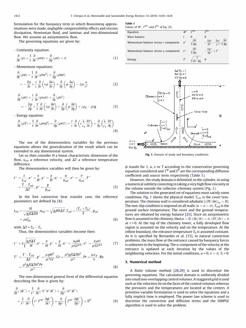
Table 1Values of F+, GF+ and S
F+ of Eq. (9).
Equation F+ GF+ SF+
Mass balance l 0 0
Momentum balance versus r component u+
ffiffiffiffiffiffiPr
r� @ pþ
þ �2uþ
2
ffiffiffiffiffiffiPr
r
T. Chergui et al. / Renewable and Sustainable Energy Reviews 14 (2010) 1410–14181412
formulation for the buoyancy term in which Boussinesq approx-imations were made, negligible compressibility effects and viscousdissipation, Newtonian fluid, and laminar and two-dimensionalflow. We assume an axisymmetric flow.
The governing equations are given by:
Ra @r rþ RaMomentum balance versus y component vþffiffiffiffiffiffiPr
r� @ pþ
þ þ Tþ
- C Ra @yEnergy T+
ffiffiffiffiffiffiffiffiffiffiffiffiffiffi1
Pr � Ra
r0
ontinuity equation:
@@tðrÞ þ 1
r
@@rðrruÞ þ @
@yðrvÞ ¼ 0 (1)
Momentum equations:
-@@tðruÞ þ 1
r
@@rðrru2Þ þ @
@yðruvÞ
¼ � @ p
@rþ 1
r
@@r
rm@u
@r
� �þ @
@ym
@u
@y
� �� 2m
u
r2(2)
@@tðrvÞ þ 1
r
@@rðrruvÞ þ @
@yðrv2Þ
¼ � @p
@yþ 1
r
@@r
rm@v@r
� �þ @
@ym
@v@y
� �þ ðr0 � rÞg (3)
Energy equation:
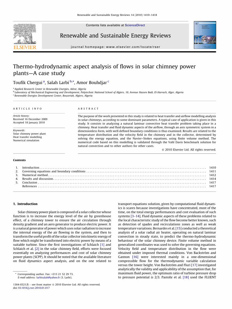
-Fig. 1. Domain of study and boundary conditions.
@@tðrTÞ þ 1
r
@@rðrruTÞ þ @
@yðrvTÞ ¼ 1
r
@@r
rlc p
@T
@r
� �þ @
@y
lc p
@T
@y
� �(4)
The use of the dimensionless variables for the previousequations allows the generalization of the result which can beextended to any dimensional system.
Let us then consider H a linear characteristic dimension of theflow, uref a reference velocity, and DT a reference temperaturedifference.
The dimensionless variables will then be given by:
tþ ¼ t
tref; xþ ¼ x
H; yþ ¼ y
H;uþ ¼ u
uref; vþ ¼ v
uref; Tþ
¼ T � Tref
DT; pþ ¼ p
pref
(5)
In the free convective heat transfer case, the referenceparameters are defined by [4]:
tref ¼Hffiffiffiffiffiffiffiffiffiffiffiffiffiffiffiffi
gbDTHp ;uref ¼
ffiffiffiffiffiffiffiffiffiffiffiffiffiffiffiffiffigbHDT
q; Tref ¼
Tc þ Thð Þ2
; pref
¼ ru2ref (6)
with DT = Th � Tc.Thus, the dimensionless variables become then:
tþ ¼ t
ffiffiffiffiffiffiffiffiffiffiffiffiffigbDT
H
s; xþ ¼ x
H; yþ ¼ y
H;uþ ¼ urH
mGr0:5; vþ ¼ vrH
mGr0:5(7)
Tþ ¼ T � Tref
DT; pþ ¼ r pH2
m2Gr;Gr ¼ r2gbDTH3
m2; Pr ¼ mc p
l;Ra
¼ r2gbDTH3Pr
m2(8)
The non-dimensional general form of the differential equationdescribing the flow is given by:
@@tþðfþÞ þ 1
rþ@
@rþðrþuþfþÞ þ @
@yþðvþfþÞ
¼ 1
rþ@
@rþrþGfþ @fþ
@rþ
!þ @
@yþGfþ @fþ
@yþ
!þ Sfþ (9)
f stands for 1, u, v or T according to the conservative governingequation considered and Gf
and Sf
are the corresponding diffusioncoefficient and source term respectively (Table 1).
However, the study domain is delimited, in the cylinder, in usinga numerical subtlety consisting in taking a very high flow viscosity inthe volume outside the collector–chimney system (Fig. 1).
The solution to the generated set of equations must satisfy someconditions. Fig. 1 shows the physical model. Tcov is the cover tem-perature. The chimney wall is considered adiabatic (ð@T=@nÞjw ¼ 0).The non-slip condition is imposed on all walls ðu ¼ v ¼ 0Þ. Tsoil is theground surface temperature. The cover and the ground tempera-tures are obtained by energy balance [25]. Since an axisymmetricflow is assumed in the chimney, then u ¼ 0; ð@v=@rÞ ¼ 0; ð@T=@rÞ ¼ 0
at r = 0. At the top of the chimney tower, a fully developed flowregion is assumed on the velocity and on the temperature. At theinflow boundary, the entrance temperature T0 is assumed constant.As it is specified by Bernardes et al. [15], in natural convectionproblems, the mass flow at the entrance caused by buoyancy forcesis unknown in the beginning. The u-component of the velocity at theentrance is updated at each iteration by the values of theneighboring velocities. For the initial conditions, u = 0; v ¼ 0; Ti = 0.
3. Numerical method
A finite volume method [28,29] is used to discretize thegoverning equations. The calculation domain is uniformly dividedinto small non-overlapping control volumes. A staggered grid is usedsuch as the velocities lie on the faces of the control volumes whereasthe pressures and the temperatures are located at the centers. Aprimitive variable formulation is used to solve the equations and afully implicit time is employed. The power law scheme is used todiscretize the convection and diffusion terms and the SIMPLEalgorithm is used to solve the problem.
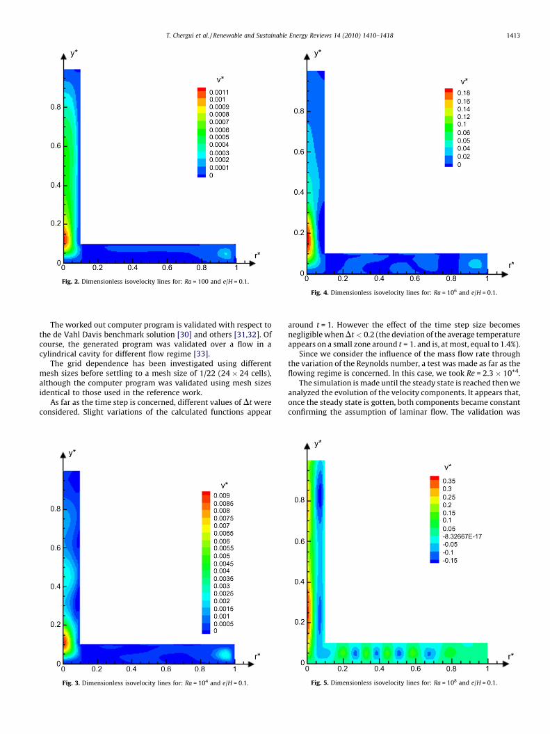
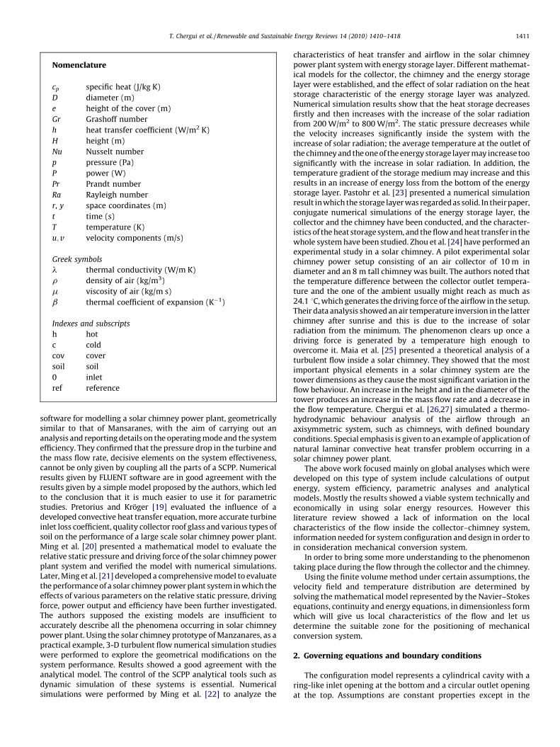
Fig. 2. Dimensionless isovelocity lines for: Ra = 100 and e/H = 0.1.
Fig. 4. Dimensionless isovelocity lines for: Ra = 106 and e/H = 0.1.
T. Chergui et al. / Renewable and Sustainable Energy Reviews 14 (2010) 1410–1418 1413
The worked out computer program is validated with respect tothe de Vahl Davis benchmark solution [30] and others [31,32]. Ofcourse, the generated program was validated over a flow in acylindrical cavity for different flow regime [33].
The grid dependence has been investigated using differentmesh sizes before settling to a mesh size of 1/22 (24 � 24 cells),although the computer program was validated using mesh sizesidentical to those used in the reference work.
As far as the time step is concerned, different values of Dt wereconsidered. Slight variations of the calculated functions appear
Fig. 3. Dimensionless isovelocity lines for: Ra = 104 and e/H = 0.1.
around t = 1. However the effect of the time step size becomesnegligible when Dt < 0.2 (the deviation of the average temperatureappears on a small zone around t = 1. and is, at most, equal to 1.4%).
Since we consider the influence of the mass flow rate throughthe variation of the Reynolds number, a test was made as far as theflowing regime is concerned. In this case, we took Re = 2.3 � 10+4.
The simulation is made until the steady state is reached then weanalyzed the evolution of the velocity components. It appears that,once the steady state is gotten, both components became constantconfirming the assumption of laminar flow. The validation was
Fig. 5. Dimensionless isovelocity lines for: Ra = 108 and e/H = 0.1.
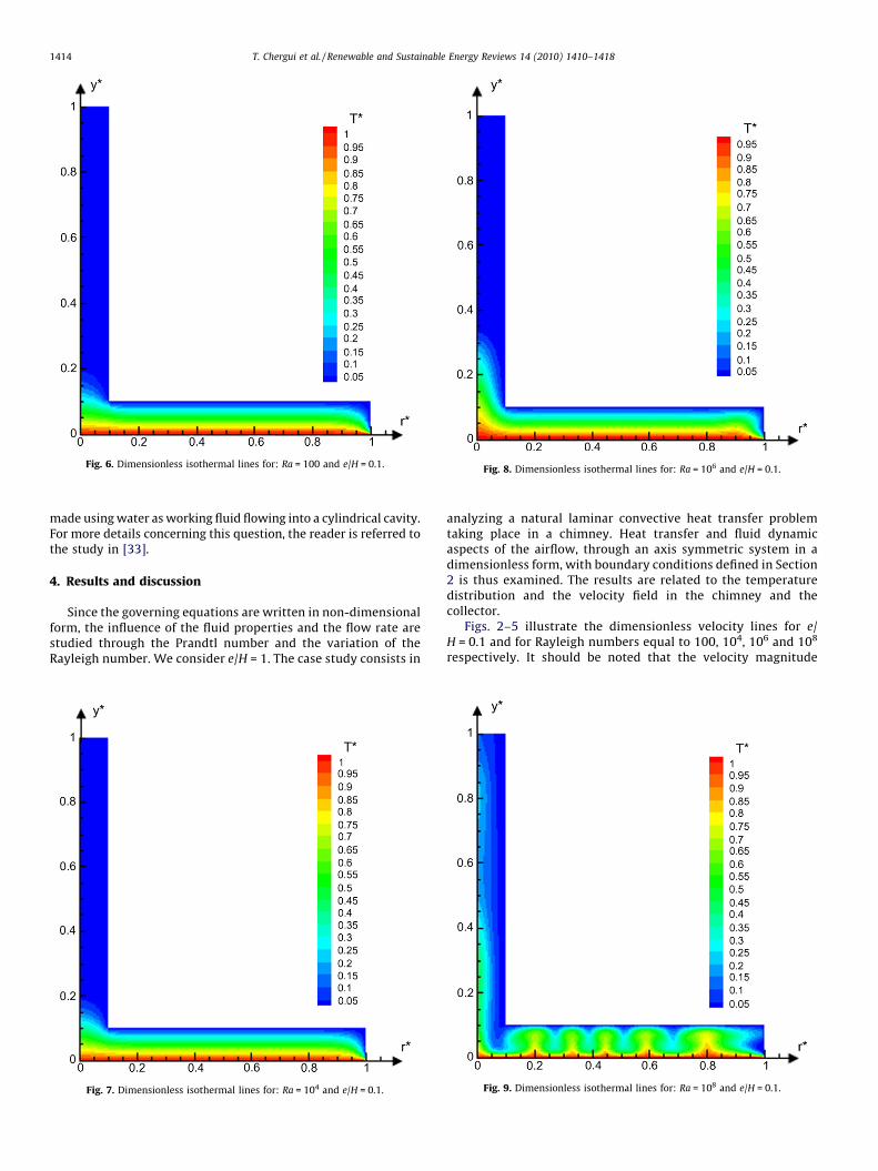
Fig. 6. Dimensionless isothermal lines for: Ra = 100 and e/H = 0.1.Fig. 8. Dimensionless isothermal lines for: Ra = 106 and e/H = 0.1.
T. Chergui et al. / Renewable and Sustainable Energy Reviews 14 (2010) 1410–14181414
made using water as working fluid flowing into a cylindrical cavity.For more details concerning this question, the reader is referred tothe study in [33].
4. Results and discussion
Since the governing equations are written in non-dimensionalform, the influence of the fluid properties and the flow rate arestudied through the Prandtl number and the variation of theRayleigh number. We consider e/H = 1. The case study consists in
Fig. 7. Dimensionless isothermal lines for: Ra = 104 and e/H = 0.1.
analyzing a natural laminar convective heat transfer problemtaking place in a chimney. Heat transfer and fluid dynamicaspects of the airflow, through an axis symmetric system in adimensionless form, with boundary conditions defined in Section2 is thus examined. The results are related to the temperaturedistribution and the velocity field in the chimney and thecollector.
Figs. 2–5 illustrate the dimensionless velocity lines for e/H = 0.1 and for Rayleigh numbers equal to 100, 104, 106 and 108
respectively. It should be noted that the velocity magnitude
Fig. 9. Dimensionless isothermal lines for: Ra = 108 and e/H = 0.1.
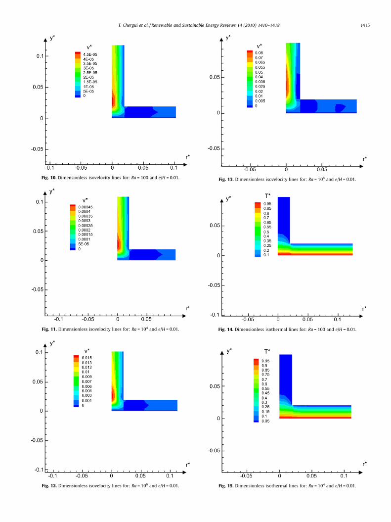
Fig. 10. Dimensionless isovelocity lines for: Ra = 100 and e/H = 0.01.
Fig. 11. Dimensionless isovelocity lines for: Ra = 104 and e/H = 0.01.
Fig. 13. Dimensionless isovelocity lines for: Ra = 108 and e/H = 0.01.
Fig. 12. Dimensionless isovelocity lines for: Ra = 106 and e/H = 0.01.
Fig. 14. Dimensionless isothermal lines for: Ra = 100 and e/H = 0.01.
Fig. 15. Dimensionless isothermal lines for: Ra = 104 and e/H = 0.01.
T. Chergui et al. / Renewable and Sustainable Energy Reviews 14 (2010) 1410–1418 1415
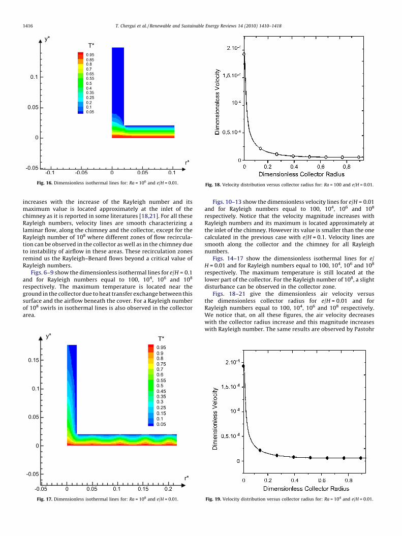
Fig. 16. Dimensionless isothermal lines for: Ra = 106 and e/H = 0.01. Fig. 18. Velocity distribution versus collector radius for: Ra = 100 and e/H = 0.01.
T. Chergui et al. / Renewable and Sustainable Energy Reviews 14 (2010) 1410–14181416
increases with the increase of the Rayleigh number and itsmaximum value is located approximately at the inlet of thechimney as it is reported in some literatures [18,21]. For all theseRayleigh numbers, velocity lines are smooth characterizing alaminar flow, along the chimney and the collector, except for theRayleigh number of 108 where different zones of flow recircula-tion can be observed in the collector as well as in the chimney dueto instability of airflow in these areas. These recirculation zonesremind us the Rayleigh–Benard flows beyond a critical value ofRayleigh numbers.
Figs. 6–9 show the dimensionless isothermal lines for e/H = 0.1and for Rayleigh numbers equal to 100, 104, 106 and 108
respectively. The maximum temperature is located near theground in the collector due to heat transfer exchange between thissurface and the airflow beneath the cover. For a Rayleigh numberof 108 swirls in isothermal lines is also observed in the collectorarea.
Fig. 17. Dimensionless isothermal lines for: Ra = 108 and e/H = 0.01.
Figs. 10–13 show the dimensionless velocity lines for e/H = 0.01and for Rayleigh numbers equal to 100, 104, 106 and 108
respectively. Notice that the velocity magnitude increases withRayleigh numbers and its maximum is located approximately atthe inlet of the chimney. However its value is smaller than the onecalculated in the previous case with e/H = 0.1. Velocity lines aresmooth along the collector and the chimney for all Rayleighnumbers.
Figs. 14–17 show the dimensionless isothermal lines for e/H = 0.01 and for Rayleigh numbers equal to 100, 104, 106 and 108
respectively. The maximum temperature is still located at thelower part of the collector. For the Rayleigh number of 108, a slightdisturbance can be observed in the collector zone.
Figs. 18–21 give the dimensionless air velocity versusthe dimensionless collector radius for e/H = 0.01 and forRayleigh numbers equal to 100, 104, 106 and 108 respectively.We notice that, on all these figures, the air velocity decreaseswith the collector radius increase and this magnitude increaseswith Rayleigh number. The same results are observed by Pastohr
Fig. 19. Velocity distribution versus collector radius for: Ra = 104 and e/H = 0.01.
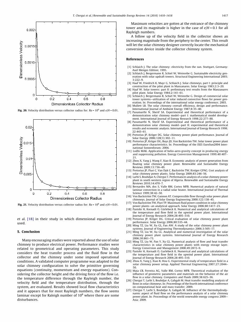
Fig. 20. Velocity distribution versus collector radius for: Ra = 106 and e/H = 0.01.
Fig. 21. Velocity distribution versus collector radius for: Ra = 108 and e/H = 0.01.
T. Chergui et al. / Renewable and Sustainable Energy Reviews 14 (2010) 1410–1418 1417
et al. [18] in their study in which dimensional equations areused.
5. Conclusion
Many encouraging studies were reported about the use of solarchimney to produce electrical power. Performance studies wererelated to geometrical and operating parameters. This studyconsiders the heat transfer process and the fluid flow in thecollector and the chimney under some imposed operationalconditions. A validated computer programme was adapted to thesolar chimney configuration to solve the primitive governingequations (continuity, momentum and energy equations). Con-sidering the collector height and the driving force of the flow i.e.the temperature difference through the Rayleigh number, thevelocity field and the temperature distribution, through thesystem, are evaluated. Results showed local flow characteristicsand it appears that for most Rayleigh numbers, the flow seemslaminar except for Raleigh number of 108 where there are somedisturbances.
Maximum velocities are gotten at the entrance of the chimneytower and its magnitude is higher in the case of e/H = 0.1 for allRayleigh numbers.
A follow up of the velocity field in the collector shows anincreasing magnitude from the periphery to the center. This resultwill let the solar chimney designer correctly locate the mechanicalconversion device inside the collector chimney system.
References
[1] Schlaich J. The solar chimney: electricity from the sun. Stuttgart, Germany:Axel Menges Edition; 1995.
[2] Schlaich J, Bergermann R, Schiel W, Weinrebe G. Sustainable electricity gen-eration with solar updraft towers. Structural Engineering International 2003;3:222–9.
[3] Haaf W, Friedrich K, Mayr G, Schlaich J. Solar chimneys, part I: principle andconstruction of the pilot plant in Manzanares. Solar Energy 1983;2:3–20.
[4] Haaf W. Solar towers: part II: preliminary test results from the Manzanarespilot plant. Solar Energy 1984;2:141–61.
[5] Schlaich J, Bergermann R, Schiel W, Weinrebe G. Design of commercial solartower systems—utilization of solar induced convective flows for power gen-eration. In: Proceedings of the international solar energy conference; 2003.
[6] Mullett LB. The solar chimney—overall efficiency, design and performance.International Journal of Ambient Energy 1987;8:35–40.
[7] Pasumarthi N, Sherif SA. Experimental and theoretical performance of ademonstration solar chimney model—part I: mathematical model develop-ment. International Journal of Energy Research 1998;22:277–88.
[8] Pasumarthi N, Sherif SA. Experimental and theoretical performance of ademonstration solar chimney model—part II: experimental and theoreticalresults and economic analysis. International Journal of Energy Research 1998;22:443–61.
[9] Pretorius JP, Kroger DG. Solar chimney power plant performance. Journal ofSolar Energy 2006;128(3):302–11.
[10] Pretorius JP, Kroger DG, Buys JD, Von Backstrom TW. Solar tower power plantperformance characteristics. In: Proceedings of the ISES EuroSun2004 Inter-national Sonnenforum; 2004.
[11] Lodhi MAK. Application of helio-aero-gravity concept in producing energyand suppressing pollution. Energy Conversion Management 1999;40:407–21.
[12] Zhou X, Yang J, Wang F, Xiao B. Economic analysis of power generation fromfloating solar chimney power plant. Renewable and Sustainable EnergyReviews 2009;13:736–49.
[13] Pretorius JP, Fluri C, Van Dyk C, Backstron TW, Kroıger GPAG. Cost analysis ofsolar chimney power plants. Solar Energy 2009;83:246–56.
[14] Larbi S, Bouhdjar A, Chergui T. Performances analysis of a solar chimney powerplant in south western region of Algeria. Renewable and Sustainable EnergyReviews 2010;14:470–7.
[15] Bernardes MA, dos S, Valle RM, Cortez MFB. Numerical analysis of naturallaminar convection in a radial solar heater. International Journal of ThermalScience 1999;38:42–50.
[16] Von Backstrom TW, Gannon AT. Compressible flow through solar power plantchimneys. Journal of Solar Energy Engineering 2000;122:138–45.
[17] Von Backstrom TW, Fluri TP. Maximum fluid power condition in solar chimneypower plants—an analytical approach. Solar Energy 2006;80:1417–23.
[18] Pastohr H, Kornadt O, Gurlebeck K. Numerical and analytical calculations ofthe temperature and flow field in the upwind power plant. InternationalJournal of Energy Research 2004;28:495–510.
[19] Pretorius JP, Kroger DG. Critical evaluation of solar chimney power plantperformance. Solar Energy 2006;80:535–44.
[20] Ming TZ, Liu W, Xu GL, Fan AW. A study of the solar chimney power plantsystems. Journal of Engineering Thermodynamics 2006;3:505–17.
[21] Ming TZ, Liu W, Xu GL. Analytical and numerical investigation of the solarchimney power plant systems. International Journal of Energy Research2006;30:861–73.
[22] Ming TZ, Liu W, Pan Y, Xu GL. Numerical analysis of flow and heat transfercharacteristics in solar chimney power plants with energy storage layer.Energy Conversion and Management 2008;49:2872–9.
[23] Pastohr H, Kornadt O, Gurlebeck K. Numerical and analytical calculations ofthe temperature and flow field in the upwind power plant. InternationalJournal of Energy Research 2004;28:495–510.
[24] Zhou X, Yang J, Xiao B, Hou G. Experimental study of temperature field in asolar chimney power setup. Applied Thermal Engineering 2007;27:2044–50.
[25] Maia CB, Ferreira AG, Valle RM, Cortez MFB. Theoretical evaluation of theinfluence of geometric parameters and materials on the behavior of the airflow in a solar chimney. Computers and Fluids 2009;38:625–36.
[26] Chergui T, Larbi S, Bouhdjar A, Gahgah M. Heat transfer modelling analysis offlows in solar chimneys. In: Proceedings of the fourth international conferenceon computational heat and mass transfer; 2009.
[27] Chergui T, Larbi S, Bouhdjar A, Gahgah M. Influence of the thermohydrody-namic aspect of fluid flow on the performance analysis of a solar chimneypower plant. In: Proceedings of the world renewable energy congress 2009—Asia; 2009.

T. Chergui et al. / Renewable and Sustainable Energy Reviews 14 (2010) 1410–14181418
[28] Beyers JHM, Harms TM, Kroger DG. A finite volume analysis of turbulentconvective heat transfer for accelerating radial flows. Numerical Heat Transfer2001;40:17–138.
[29] Patankar SV. Numerical heat transfer and fluid flow. New York, USA: Hemi-sphere Publishing Corporation Edition; 1980.
[30] de Vahl Davis G. Natural convection of air in a square cavity: A Benchmarknumerical solution. International Journal of Numerical Methods in Fluids1983;3:249–64.
[31] Markatos NK, Pericleous KA. Laminar and turbulent natural convection in anenclosed cavity. International Journal of Heat and Mass Transfer1984;27:755–72.
[32] Aggarwal SK, Manhapra A. Use of heatlines for unsteady buoyancy-driven flowin a cylindrical enclosure. International Journal Heat Transfer 1989;111:576–88.
[33] Bouhdjar A, Harhad A, Benkhelifa A. Numerical simulation of transient mixedconvection in a cylindrical cavity. Numerical Heat Transfer 1996;31:305–24.


