Embed Size (px)
Citation preview

J6
Raavtedbsa
S
P
C
p
a
M
D
H
e
©
0
d
Oral Maxillofac Surg7:2080-2092, 2009
Three-Dimensional Treatment Planningof Orthognathic Surgery in the Era of
Virtual ImagingGwen R.J. Swennen, MD, LDS, DMD, PhD, FEBOMFS,*
Wouter Mollemans, MSc, PhD,† and Filip Schutyser, MSc‡
Purpose: The aim of this report was to present an integrated 3-dimensional (3D) virtual approachtoward cone-beam computed tomography-based treatment planning of orthognathic surgery in theclinical routine.
Materials and Methods: We have described the different stages of the workflow process for routine3D virtual treatment planning of orthognathic surgery: 1) image acquisition for 3D virtual orthognathicsurgery; 2) processing of acquired image data toward a 3D virtual augmented model of the patient’s head;3) 3D virtual diagnosis of the patient; 4) 3D virtual treatment planning of orthognathic surgery; 5) 3Dvirtual treatment planning communication; 6) 3D splint manufacturing; 7) 3D virtual treatment planningtransfer to the operating room; and 8) 3D virtual treatment outcome evaluation.
Conclusions: The potential benefits and actual limits of an integrated 3D virtual approach for thetreatment of the patient with a maxillofacial deformity are discussed comprehensively from our expe-rience using 3D virtual treatment planning clinically.© 2009 American Association of Oral and Maxillofacial Surgeons
J Oral Maxillofac Surg 67:2080-2092, 2009afi(hvsdai
flnivqmoon3iu
dtf
ecent advances in 3-dimensional (3D) medical im-ge computing for orthognathic surgery have en-bled a major breakthrough and allowed unprecedentedirtual diagnosis, treatment planning, and evaluation ofreatment outcomes of maxillofacial deformities. How-ver, to enable the clinician to make this major para-igm shift in routine planning of orthognathic surgery,oth image acquisition systems and 3D virtual planningoftware must become user-friendly, easily accessible,nd available at a relatively low cost.
*Private Practice, Division of Maxillofacial Surgery, Department of
urgery, General Hospital St-Jan Bruges, Bruges, Belgium, Associate
rofessor, Medical University Hannover, Hannover, Germany; and
o-Founder, 3D Facial Imaging Research Group, Bruges, Belgium.
†Research Engineer, Medical Image Computing, University Hos-
ital Gasthuisberg Faculties of Medicine and Engineering, Leuven,
nd Digital Dentistry of Medicim, Mechelen, Belgium.
‡Global Solutions Manager, Digital Dentistry of Medicim,
echelen, Belgium.
W.M. and F.S. are members of the Nobel Biocare Group.
Address correspondence and reprint requests to Dr Swennen:
ivision of Maxillofacial Surgery, Department of Surgery, General
ospital St-Jan Bruges, Ruddershove 10, Bruges 8000 Belgium,
-mail: [email protected]
2009 American Association of Oral and Maxillofacial Surgeons
278-2391/09/6710-0007$36.00/0
noi:10.1016/j.joms.2009.06.007
2080
To reach the present stage in which an integratedpproach of 3D orthognathic surgery has becomeeasible, a lot of problems had to be solved. First, 3Dmaging of the patient in the natural head positionNHP), capturing the hard and soft tissues and teeth,ad to be possible at a low radiation dose. All con-entional tools for planning of orthognathic surgeryuch as cephalometry, anthropometry of the face,ental model analysis, plaster dental model surgery,nd soft-tissue simulation had to be developed andmplemented in a single software platform.
The aim of the present study was to report a work-ow process (Fig 1) for routine 3D treatment plan-ing of orthognathic surgery in the era of virtual
maging consisting of 1) image acquisition for 3Dirtual orthognathic surgery; 2) processing of the ac-uired image data toward a 3D virtual augmentedodel of the patient’s head; 3) a 3D virtual diagnosis
f the patient; 4) 3D virtual treatment planning of therthognathic surgery; 5) 3D virtual treatment plan-ing communication; 6) 3D splint manufacturing; 7)D virtual treatment planning transfer to the operat-
ng room; and 8) 3D virtual treatment outcome eval-ation.We have not intended to provide evidence but to
iscuss comprehensively the benefits and the poten-ial, but especially the actual, limits as determinedrom our experience with 3D virtual treatment plan-
ing of orthognathic surgery clinically. We have
tc3si
IO
trbtrcagmamitiess(
fistOsomtpsvtttiptsAcHqdttne
Fa
S
SWENNEN, MOLLEMANS, AND SCHUTYSER 2081
herefore referred, in particular, to our work and haveredited all other research groups in this field. Finally,D virtual treatment planning requires a good under-tanding of the patient’s needs, a good clinical exam-nation, and clinical experience.
mage Acquisition for 3D Virtualrthognathic Surgery
To enable proper planning of orthognathic surgery,he patient should undergo imaging in the NHP withelaxed facial soft tissues. The introduction of cone-eam computed tomography (CBCT) scanners withhe potential to vertically scan the patient with a lowadiation dose1 and a scanned volume large enough toapture the entire face (triad of hard and soft tissuesnd teeth) will revolutionize how orthognathic sur-ery will be planned in the future.2 CBCT is a volu-etric image acquisition technique that offers unique
ccessibility because of its low costs compared withultislice CT (MSCT) and the potential for in-office
maging. The ideal CBCT apparatus for 3D virtualreatment planning of orthognathic surgery, however,s not yet available. A number of problems will bencountered in the routine clinical situation. First, thecanned volume of CBCT scanners is currently toomall to capture all types of maxillofacial deformities
IGURE 1. Workflow process for 3D virtual treatment planning of ore illustrated using a clinical case other than the case discussed i
wennen, Mollemans, and Schutyser. Three-Dimensional Treatm
Fig 2). Depending on the type of CBCT scanner, the T
eld of view is too short in height and does not allowcanning of the patient from the upper limit of thehyroid up to 2 cm above the superior orbital rim.ther CBCT scanners have a field of view that is too
hort in depth and do not allow capturing both pori-ns and the tip of the nose with a sufficient freeargin. The image volume of CBCT is dependent on
he shape of the x-ray beam and the size of the flatanel detector. Owing to the relatively small detectorize of the available CBCT apparatus, the scannedolume is limited. With the fast evolution in detectorechnology, it is expected that CBCT with larger de-ectors will become available and eliminate this limi-ation in the near future. Second, because of the limitsn the scanned volume, accurate positioning of theatient in the NHP in the CBCT apparatus is some-imes difficult or not feasible. Because of the longcan times (eg, 40 s with the Iluma CBCT, Imtec,rdmore, OK) or 2 scan times (eg, 2 � 20 s with thelassic iCAT CBCT, Imaging Sciences International,atfield, PA), patients might move during image ac-uisition, resulting in movement artifacts and uselessata. Improvements in CBCT hardware and softwareo allow larger scanned volumes and decreased scanimes are expected to solve these problems in theear future. Furthermore, in-office CBCT imaging byxperienced personnel is key for good-quality data.
athic surgery. Note, the different steps of the 3D workflow processrticle.
nning for Orthognathic Surgery. J Oral Maxillofac Surg 2009.
rthognn this a
ent Pla
hird, the higher noise level, lower contrast, higher
racatpsrsaSrpildrtFCstfaqpt
Cmtsplem
P3P
spuvtmiag“cssavp
asaagpgtpmesobcTplstid
Ffiwm
Sm2
2082 THREE-DIMENSIONAL TREATMENT PLANNING FOR ORTHOGNATHIC SURGERY
esolution, and image quality limitations of CBCT im-ging compared with MSCT imaging should also beonsidered. The gray values of a CBCT scan have nobsolute Hounsfield unit calibration. The gray value ofhe same tissue changes between scans and with theosition of that tissue in the field of view of thecanner. Because most tissue segmentation algo-ithms are based on thresholding, some anatomictructures (eg, sella turcica, condyles, orbital walls)re difficult to visualize anatomically in the 3D viewer.everal improvements in CBCT reconstruction algo-ithms have already been made and more are ex-ected in the near future. Fourth, although CBCT
maging produces fewer artifacts at the occlusalevel than MSCT imaging, a single scanning proce-ure of the patient’s head does not allow for accu-ate occlusal and intercuspidation data. However,his problem has recently been solved (see below).inally, the fast evolution in acquisition software ofBCT scanners inherently necessitates frequentoftware updates for the purchased CBCT appara-us. The clinician is, therefore, frequently con-ronted with changes in image quality or imagertifacts after such software updates, which can beuite frustrating. Good support from the companyroviding the CBCT scanner in case of problems is
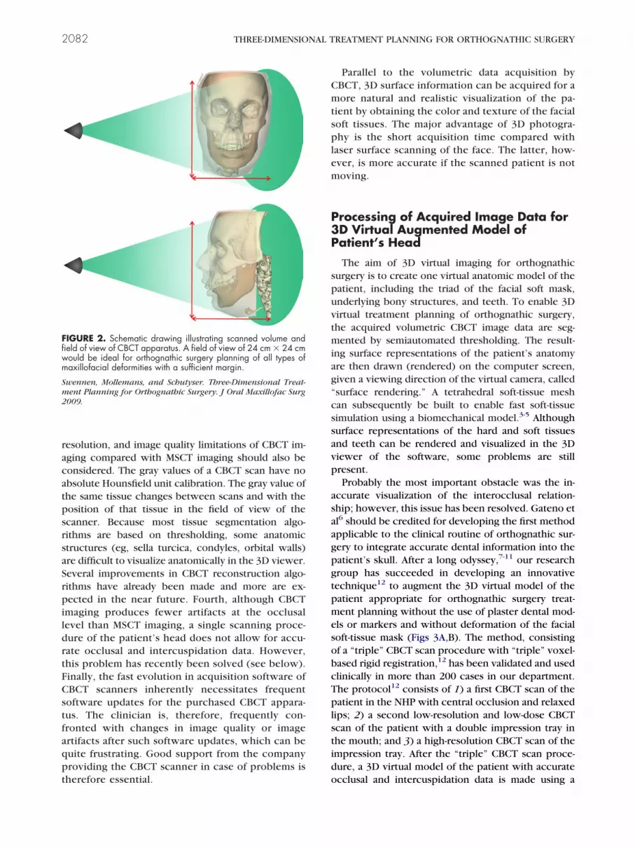
IGURE 2. Schematic drawing illustrating scanned volume andeld of view of CBCT apparatus. A field of view of 24 cm � 24 cmould be ideal for orthognathic surgery planning of all types ofaxillofacial deformities with a sufficient margin.
wennen, Mollemans, and Schutyser. Three-Dimensional Treat-ent Planning for Orthognathic Surgery. J Oral Maxillofac Surg
009.
herefore essential. o
Parallel to the volumetric data acquisition byBCT, 3D surface information can be acquired for aore natural and realistic visualization of the pa-
ient by obtaining the color and texture of the facialoft tissues. The major advantage of 3D photogra-hy is the short acquisition time compared with
aser surface scanning of the face. The latter, how-ver, is more accurate if the scanned patient is notoving.
rocessing of Acquired Image Data forD Virtual Augmented Model ofatient’s Head
The aim of 3D virtual imaging for orthognathicurgery is to create one virtual anatomic model of theatient, including the triad of the facial soft mask,nderlying bony structures, and teeth. To enable 3Dirtual treatment planning of orthognathic surgery,he acquired volumetric CBCT image data are seg-ented by semiautomated thresholding. The result-
ng surface representations of the patient’s anatomyre then drawn (rendered) on the computer screen,iven a viewing direction of the virtual camera, calledsurface rendering.” A tetrahedral soft-tissue meshan subsequently be built to enable fast soft-tissueimulation using a biomechanical model.3-5 Althoughurface representations of the hard and soft tissuesnd teeth can be rendered and visualized in the 3Diewer of the software, some problems are stillresent.Probably the most important obstacle was the in-
ccurate visualization of the interocclusal relation-hip; however, this issue has been resolved. Gateno etl6 should be credited for developing the first methodpplicable to the clinical routine of orthognathic sur-ery to integrate accurate dental information into theatient’s skull. After a long odyssey,7-11 our researchroup has succeeded in developing an innovativeechnique12 to augment the 3D virtual model of theatient appropriate for orthognathic surgery treat-ent planning without the use of plaster dental mod-
ls or markers and without deformation of the facialoft-tissue mask (Figs 3A,B). The method, consistingf a “triple” CBCT scan procedure with “triple” voxel-ased rigid registration,12 has been validated and usedlinically in more than 200 cases in our department.he protocol12 consists of 1) a first CBCT scan of theatient in the NHP with central occlusion and relaxed
ips; 2) a second low-resolution and low-dose CBCTcan of the patient with a double impression tray inhe mouth; and 3) a high-resolution CBCT scan of thempression tray. After the “triple” CBCT scan proce-ure, a 3D virtual model of the patient with accurate
cclusal and intercuspidation data is made using a
s“
(iiustvip(
iH“itc“vv“an
Fit
S Plann
SWENNEN, MOLLEMANS, AND SCHUTYSER 2083
emiautomated procedure and the 3 consecutivevoxel-based” registrations.12
To improve 3D soft-tissue simulation algorithmssee below), it was essential to integrate accuratenterocclusal data without any soft-tissue disturbancesnto the 3D patient model of the head to secure annbiased virtual preoperative setting before virtualimulation. The next challenge is to further augmenthe patient’s CBCT model of the head with detailedisualization of the dental roots. “Surface rendering”s based on thresholding and currently leads to im-roper visualization of certain anatomic structures
IGURE 3. 3D hard tissue surface representations of patient A,ntercuspidating data according to “triple” CBCT scan procedure witexture information determined from arbitrary set of 2-dimensional ph
wennen, Mollemans, and Schutyser. Three-Dimensional Treatment
eg, sella turcica, condyles, orbital walls) owing to the o
nherent inhomogenity of the CBCT gray value data.owever, a volume of voxels can be rendered with
volume rendering.” For each voxel, a color and opac-ty can be assigned, and a projection image accordingo the viewing direction of the virtual camera can beomputed and presented on the computer screen.Volume rendering” of the acquired image data pro-ides beautiful anatomic images and is useful for 3Dirtual diagnosis of the patient’s anatomy. Becausevolume rendering” is still computationally complexnd it is expensive to manipulate the image data, it isot yet suitable for 3D virtual treatment planning
and B, after, augmenting skull model with detailed occlusal ande” voxel-based registration. C, Same patient with detailed soft-tissuehs (Maxilim, version 2.2.2, Medicim NV, Mechelen, Belgium).
ing for Orthognathic Surgery. J Oral Maxillofac Surg 2009.
beforeh “triplotograp
f orthognathic surgery. Therefore, mixing “surface”
acats
oatmmaapCcs
3
ahaBfpisaoacmsdfrbicmlStvsspbaf(wsv
ttfwmaoTso3psrg
3O
nohparpttcyBofmpcoacUv(fissticpivdct
2084 THREE-DIMENSIONAL TREATMENT PLANNING FOR ORTHOGNATHIC SURGERY
nd “volume” rendering probably will allow one toombine the benefits of both rendering techniquesnd is a very promising approach. It is expected thathis “mixed” visualization approach will become pos-ible in the near future.
Another issue is that the facial soft-tissue maskbtained by CBCT imaging looks unnatural and is notrealistic view of the patient. Sophisticated registra-
ion algorithms to further augment the patient’s CBCTodel of the head with skin texture and color infor-ation to enable a more natural looking rendering are
lready available. Using a 3D photograph13,14 or anrbitrary set of 2-dimensional photographs15 of theatient with the same facial expression as duringBCT scanning, highly detailed texture informationan be added to the skin, segmented out of the CBCTcan (Fig 3C).
D Virtual Diagnosis of Patient
The combination of a good clinical examinationnd 3D inspection of the virtual model of the patient’sead has an unprecedented potential toward the di-gnosis of the patient with a maxillofacial deformity.oth “volume rendering” and “surface rendering” of-
er a thorough in-depth 3D virtual inspection of theatient’s anatomy in the 3D virtual scene. Both view-
ng methods also incorporate the original axial CBCTlices and coronal and sagittal reconstructions, whichllow 2-dimensional inspection of the patient’s anat-my in the 3 standard planes (axial, sagittal, coronal)nd multiplanar planes. A large amount of relevantlinical information with regard to the patient with aaxillofacial deformity can be gleaned from these
lices (eg, condylar anatomy, maxillofacial bony andental pathologic features, maxillary sinus pathologiceatures, nasal septum deviation, hypertrophic infe-ior turbinates, a restricted airway, dentoalveolarone support to the teeth, and the pathway of the
nferior alveolar nerve; Fig 4). Volume rendering isurrently the most appropriate for 3D virtual assess-ent of the roots of the teeth, the temporomandibu-
ar joints, and the airway (Fig 5; see also Fig 12).urface rendering offers great potential to implementhe related data in the 3D virtual viewer such asirtual measurement and osteotomy tools and virtualurgical devices (eg, virtual surgical splints). Usingurface rendering (Fig 6), 2 innovative virtual ap-roaches were developed and subsequently com-ined by our research group. First, a new virtualpproach was developed in which virtual lateral androntal cephalograms were calculated from the CTCBCT or MSCT) data set of the patient and linkedith the hard and soft-tissue surface-rendered repre-
entations. This approach allowed us to bridge con-
entional cephalometry with 3D cephalometry of lhe facial soft-tissue mask and underlying bone andeeth with a common 3D cephalometric referencerame.16-18 Second, the “triple CBCT scan protocol”as developed and validated and allows one to aug-ent the virtual model of the patient’s head to be
ppropriate for orthognathic surgery planning with-ut the use of markers and plaster dental models.7-12
he latter developments were key toward the pre-ented 3D virtual approach of treatment planning ofrthognathic surgery. A current disadvantage of theD virtual approach is the static diagnosis of theatient. The virtual dynamic diagnosis (four dimen-ions) of the patient (eg, smile esthetics, habits) hasecently been introduced and will probably be inte-rated in the future.
D Virtual Treatment Planning ofrthognathic Surgery
One of the important advantages of 3D virtual plan-ing compared with conventional treatment planningf orthognathic surgery is that the clinician inherentlyas more information on the patient’s anatomy duringlanning. Moreover, 3D virtual treatment planningllows one to focus more on 3D facial harmonization,ather than on the facial profile. A standardized ap-roach toward 3D virtual treatment planning of or-hognathic surgery, which includes 4 consecutive vir-ual planning steps (VPSs) (Fig 7), is used in ourlinical practice: VPS1, 3D Bruges cephalometric anal-sis for the ideal facial soft-tissue mask; VPS2, 3Druges 3D soft-tissue analysis; VPS3, 3D virtual osteot-mies; and VPS4, 3D virtual surgery toward the idealacial soft-tissue mask. VPS1 consists of 3D cephalo-etric analysis (11 angles, 7 linear distances, and 2 facialroportions) of the hard and soft tissues and teeth usingonventional cephalometric analysis performed in theral maxillofacial department of Bruges for clinicalnd scientific purposes. Moreover, 4 additional verti-al orthogonal measurements (UMcuspr-xPl, UCr-xPl,Cl-xPl, and UMcuspl-xPl) were included to verify theertical position of the repositioned maxilla at 4 levelsboth canines and both mesial buccal cusps of therst molars) during surgery (see below). VPS2 con-ists of additional 3D soft tissue cephalometric analy-is (2 angles, 10 linear distances, and 4 facial propor-ions) using direct anthropometric analysis performedn the oral maxillofacial department of Bruges forlinical and scientific purposes. In VPS3, the mosterformed facial osteotomies (Le Fort I, bilateral sag-
ttal split osteotomy, and chin) are routinely doneirtually, which creates the potential to virtually con-uct different surgical treatment plans. Finally, VPS4onsists of virtual surgery toward the ideal facial soft-issue mask, including virtual occlusal definition. The
atter consists of a best fit between the dental arches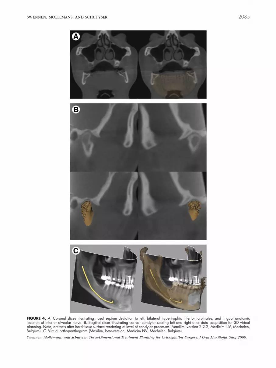
FlpB
S
SWENNEN, MOLLEMANS, AND SCHUTYSER 2085
IGURE 4. A, Coronal slices illustrating nasal septum deviation to left, bilateral hypertrophic inferior turbinates, and lingual anatomicocation of inferior alveolar nerve. B, Sagittal slices illustrating correct condylar seating left and right after data acquisition for 3D virtuallanning. Note, artifacts after hard-tissue surface rendering at level of condylar processes (Maxilim, version 2.2.2, Medicim NV, Mechelen,elgium). C, Virtual orthopanthogram (Maxilim, beta-version, Medicim NV, Mechelen, Belgium).
wennen, Mollemans, and Schutyser. Three-Dimensional Treatment Planning for Orthognathic Surgery. J Oral Maxillofac Surg 2009.

gbdgofsp(mscmlmddspnrraw(idmt
tpvFbt3sftbompcndwfdmcwo(af
FecyM
S
FrP
Sm2
2086 THREE-DIMENSIONAL TREATMENT PLANNING FOR ORTHOGNATHIC SURGERY
uided by virtual elastics and subsequently visualizedy a color scale. The present study has not reported inetail on the different VPSs. Moreover, especially re-arding VPS1 and VPS2, different surgeons and orth-dontists have their proper measurements they pre-er. Unpublished data, however, from a prospectivetudy of 50 patients, showed that VPS1 to VPS3 can beerformed within a clinically acceptable periodVPS1, 11.46 � 0.23 minutes; VPS2, 3.46 � 0.18inutes; and VPS3, 5.38 � 0.33 minutes). VPS4 was
till very time-consuming (23.17 � 1.31 minutes) be-ause of the virtual occlusal definition (15.45 � 0.87inutes) and can be improved by increasing the
earning curve and, especially, software improve-ents. Particularly for nonharmonized orthodontic
ental arches or segmental surgery, virtual occlusalefinition is still very demanding. Improvements inoftware are therefore mandatory and could solve thisroblem. The routine clinical use of 3D virtual plan-ing also showed that 3D soft-tissue simulation stillequires a number of improvements and cannot beelied on, especially for patients with long faces andsymmetries. One should, therefore, be very carefulith the setup of the ideal virtual 3D soft-tissue planes
eg, ideal modified Burstone profile plane, ideal mod-fied Ricketts lip plane), because these planes areetermined by the subnasal and lip soft-tissue land-arks, which are inherently modified by 3D soft-
IGURE 5. Volume rendering showing 3D visualization of toothoots and volume quantification of airway (Dolphin Imaging 11.0remium, Chatsworth, CA).
wennen, Mollemans, and Schutyser. Three-Dimensional Treat-ent Planning for Orthognathic Surgery. J Oral Maxillofac Surg
009.
issue simulation that is not yet reliable.m2
Despite the latter disadvantages, some major advan-ages were experienced using 3D virtual treatmentlanning in the clinical routine compared with con-entional orthognathic surgery treatment planning.irst, the occlusal plane cant in the frontal plane cane accessed much more accurately (and subsequentlyransferred to the patient using a 3D surgical splint) indimensions just as done conventionally (eg, wooden
patula, face bow transfer). The correction of therontal occlusal plane cant has an important effect onhe paranasal area, gonial angles, lower mandibularorders, and chin. Second, the upper dental midline isften clinically misjudged, because it is often deter-ined in a clinical setting for the esthetic collumela-hiltrum unit, which can be deviated (Fig 8; eg, in thease of frontal occlusal plane tilting, deviated anteriorasal spine, or nasal floor asymmetry). The upperental midline can be assessed more accurately to-ard the facial midline (and also subsequently trans-
erred to the patient using a 3D surgical splint) in 3imensions, just as conventionally. The upper dentalidline can be corrected by a rotation, translation, or
ombined rotation and translation of the maxilla to-ard the skull base. This will have an important effectn the symmetry of the lower face and facial harmonyFig 9). Third, the chin position and anatomy can bessessed much more accurately in 3 dimensions in therontal (transverse and vertical asymmetries) and base
IGURE 6. Surface rendering illustrating hard-tissue and transpar-nt soft-tissue surface representations linked with virtual lateralephalogram, allowing thorough in-depth 3D cephalometric anal-sis of soft and hard tissues and teeth (Maxilim, version 2.2.2,edicim NV, Mechelen, Belgium).
wennen, Mollemans, and Schutyser. Three-Dimensional Treat-
ent Planning for Orthognathic Surgery. J Oral Maxillofac Surg009.

(pmcwmcdFbctp
3P
otbrsdd
ptiv
tcemScaatmlcowitwt
nmsvpccrpso
F1B
Sm2
Fnv
S
SWENNEN, MOLLEMANS, AND SCHUTYSER 2087
transverse deviations, exostoses, and so forth)lanes. Fourth, because the proximal virtual frag-ents of the mandible remain stable and thus the
ondyles remain seated (if the initial data acquisitionas well done) during virtual surgery, the amount ofandibular movement (advancement or setback,
lockwise or counterclockwise, and medial or lateraleviation) can accurately be measured on both sides.inally, different virtual surgical treatment plans (eg,imaxillary rotation clockwise vs counterclockwise)an be evaluated. An important issue that remains iso determine 3D virtual mandibular autorotation, es-ecially in the case of maxillary extrusion.
D Virtual Treatmentlanning Communication
One of the major disadvantages of conventionalrthognathic surgery planning is communicating thereatment plan of a patient determined using the com-ination of a good clinical examination, clinical expe-ience, and a broad variety of diagnostic informationuch as lateral and frontal cephalograms, clinical stan-ardized photographs, a profile prediction tracing,ental models, and model articulator surgery.Three-dimensional virtual orthognathic surgery
lanning has powerful potential as a communicationool because it offers the possibility to visualize anntegrated treatment plan of the patient as a single
IGURE 7. 3D virtual treatment planning after 4 consecutive VPSto 4 performed (Maxilim, version 2.2.2, Medicim NV, Mechelen,elgium).
wennen, Mollemans, and Schutyser. Three-Dimensional Treat-ent Planning for Orthognathic Surgery. J Oral Maxillofac Surg
009.
irtual anatomic model including the hard and softm2
issues and teeth. First, the 3D virtual treatment planan be saved in a viewer format that can be sent bylectronic mail to the referring orthodontist to com-unicate and discuss the patient’s treatment plan.
econd, the 3D virtual treatment plan can be dis-ussed with the patient and optimized and individu-lized to the patient’s needs. Third, the 3D virtualpproach offers an excellent communication tool toeach contemporary treatment of maxillofacial defor-ity to residents in orthodontics and oral and maxil-
ofacial surgery. Fourth, the surgeon or orthodontistan easily communicate the 3D virtual treatment planf a difficult case to another colleague worldwideith more experience with a typical pathologic find-
ng to obtain advice (electronic counseling). Finally,he 3D virtual approach could improve knowledgeorldwide on maxillofacial deformities with elec-
ronic learning and electronic teaching (Fig 1).Although 3D virtual treatment planning of orthog-
athic surgery offers an unprecedented tool in com-unication with patients and colleagues, it does have
ome disadvantages. First, the viewer format of the 3Dirtual treatment planning necessitates a personal com-uter workstation with good graphic ability, which isurrently not standard. Because recent commer-ially available personal computers have incorpo-ated more and more powerful graphic ability, thisroblem will soon be eliminated. Also, because 3Doft-tissue simulation still requires improvement,ne should be careful in communicating this infor-
IGURE 8. Clinical photograph showing upper dental midline hasot deviated regarding esthetic collumella-philtrum unit (Maxilim,ersion 2.2.2, Medicim NV, Mechelen, Belgium).
wennen, Mollemans, and Schutyser. Three-Dimensional Treat-
ent Planning for Orthognathic Surgery. J Oral Maxillofac Surg009.

Fsri
S
2088 THREE-DIMENSIONAL TREATMENT PLANNING FOR ORTHOGNATHIC SURGERY
IGURE 9. Virtual correction of occlusal plane tilting and upper dental midline deviation by combined rotation and translation to right of maxillahowing A, effect on mandibular border gonial angle symmetry and chin position. Note, the mandible was put virtually into occlusion with theepositioned maxilla and the chin was not virtually repositioned. B, Isolated 3D virtual repositioning of the maxilla and visualization of thentermediate surgical splint to transfer virtual repositioning of the maxilla to the patient (Maxilim, version 2.2.2, Medicim NV, Mechelen, Belgium).
wennen, Mollemans, and Schutyser. Three-Dimensional Treatment Planning for Orthognathic Surgery. J Oral Maxillofac Surg 2009.

mlsia
3
smsassgsugC
ttsmovactvoep3tcvtut
lint (M
S ent Pla
Fr
S
SWENNEN, MOLLEMANS, AND SCHUTYSER 2089
ation to the patient, especially for patients with aong faces and facial asymmetries. It is clear thatoft-tissue simulation algorithms will substantiallymprove in the future with the input of a largemount of 3D data.
D Surgical Splint Manufacturing
Once the final 3D virtual treatment plan has beenet up, the necessary 3D virtual surgical splints can beade (Fig 10). Subsequently, the 3D virtual surgical
plints are processed using computer-aided designnd computer-aided manufacturing techniques intourgical splints that can be used during the actualurgery. Gateno et al19 have shown that stereolitho-raphic surgical splints fit the same as conventionalurgical splints. Our research group is currently eval-ating and validating another process to produce sur-ical wafers by milling instead of stereolithography.ompared with conventional surgical splints, 3D vir-
FIGURE 10. 3D virtual intermediate and final surgical sp
wennen, Mollemans, and Schutyser. Three-Dimensional Treatm
IGURE 11. Illustration of synthetic cadaver skull showing useepositioned maxilla at 4 levels (both canines and both mesial buc
wennen, Mollemans, and Schutyser. Three-Dimensional Treatment Pla
ually made surgical splints using our approach seemo have the following advantages: 1) the surgicalplints are directly made using the 3D virtual aug-ented model of the patient without the intermediate
f plaster dental models; and 2) the intermediate 3Dirtually made surgical splint can incorporate moreccurately the surgical treatment plan, especially inomplex cases with combined leveling, rotation, andranslation movements of the jaw. To use the 3Dirtual made surgical splints in the clinical routine ofrthognathic surgery, some important problems stillxist. First, the base material for 3D surgical splintroduction must be medically approved. Second, theD surgical splints are still too bulky and need to berimmed manually by the surgeon, which is time-onsuming. It is expected that this will be solved byirtual trimming before processing and refinement ofhe computer-aided design and computer-aided man-facturing techniques. Finally, the manufacturing ofhe 3D surgical splints is still a time-consuming pro-
axilim, version 2.2.2, Medicim NV, Mechelen, Belgium).
nning for Orthognathic Surgery. J Oral Maxillofac Surg 2009.
mercially available calipers to verify the vertical position of thesps of first molars).
of comcal cu
nning for Orthognathic Surgery. J Oral Maxillofac Surg 2009.

cpstppsvti
3t
tStpisIaictibppitmudpbtbapatioe
Fi
Sm2
Fa
S
2090 THREE-DIMENSIONAL TREATMENT PLANNING FOR ORTHOGNATHIC SURGERY
ess. The clinician must upload the virtual treatmentlanning data to be processed out of office, and theurgical wafer or wafers need to be shipped back tohe clinician. Decreasing the time for out-of-officerocessing or in-office manufacturing could solve thisroblem. Finally, 3D surgical splints for segmentalurgery are still very demanding in the presented 3Dirtual approach, because virtual occlusal definition ofhe segmented jaws is still very difficult. Once again,mprovements in software will solve this problem.
IGURE 12. Volume-rendered postoperative frontal view (Max-lim, version 2.2.2, Medicim, Belgium).
wennen, Mollemans, and Schutyser. Three-Dimensional Treat-ent Planning for Orthognathic Surgery. J Oral Maxillofac Surg
009.
IGURE 13. Surface-rendered hard-tissue representations after vofter bimaxillary surgery (Maxilim, version 2.2.2, Medicim NV, M
wennen, Mollemans, and Schutyser. Three-Dimensional Treatment Pla
D Virtual Treatment Planning Transfero Operating Room
The 3D virtual surgical treatment plan can be easilyransferred to the operating room in a viewer format.urgeons, anesthesiologists, and nurses have access tohe individualized 3D virtual treatment plan of theatient at any time during surgery. To transfer the
ndividualized 3D virtual treatment to the patient, 3Durgical wafers and calipers are used in our approach.n our surgical approach, the maxilla is repositionednd ostheosynthesized first during bimaxillary surgeryn most cases. For maxillary repositioning, the 3D surgi-al wafer transfers the entire 3D virtual repositioning ofhe maxilla (including rotations, translations, and level-ng), except for its vertical position to the cranialase. Theoretically, the vertical position of the re-ositioned maxilla should be verified at only oneoint. We currently use commercially available cal-
pers to verify the vertical position of the reposi-ioned maxilla at 4 levels (both canines and bothesial buccal cusps of the first molars) (Fig 11)
sing the patient’s 3D cephalometric data. For man-ibular repositioning, the 3D surgical wafer incor-orates the 3D virtual repositioning of the mandi-le; and for chin repositioning, calipers are used toransfer the 3D virtual plan. A prospective study iseing conducted to evaluate the accuracy of thispproach of transferring the 3D virtual treatmentlan to the patient. If the results show that thispproach is not accurate enough clinically, otherechniques, such as guidance by intraoperative nav-gation, intraoperative imaging with C-arm CBCT,r prebent osteosynthesis plates, should be consid-red and investigated.
sed superimpositioning on the cranial base before and 6 monthsn, Belgium).
xel-baechele
nning for Orthognathic Surgery. J Oral Maxillofac Surg 2009.

3O
piatihh
waswtowCbtiopmttsym
ttsstwf
swoiattHt
FtaM
Sm2
F6
S
SWENNEN, MOLLEMANS, AND SCHUTYSER 2091
D Virtual Treatmentutcome Evaluation
Probably the most powerful aspect of 3D treatmentlanning of orthognathic surgery in the era of virtual
maging is the unprecedented potential for the evalu-tion of the treatment outcome (Figs 12-15). Theechniques of voxel-based rigid registration and super-mposition on a 3D cephalometric reference systemave been extensively described.2 Cevidanes et al20-22
ave made a major contribution to the published data
IGURE 14. Surface-rendered right profile soft-tissue representa-ions after voxel-based superimpositioning on cranial base beforend 6 months after bimaxillary surgery (Maxilim, version 2.2.2,edicim NV, Mechelen, Belgium).
wennen, Mollemans, and Schutyser. Three-Dimensional Treat-ent Planning for Orthognathic Surgery. J Oral Maxillofac Surg
009.
IGURE 15. Surface-rendered base view of soft-tissue representatmonths after bimaxillary surgery (Maxilim, version 2.2.2, Medic
wennen, Mollemans, and Schutyser. Three-Dimensional Treatment Pla
ith their clinical research work. We suggest evalu-ting the treatment outcome using CBCT imaging in 3tages. First, CBCT should be performed at 3 to 6eeks postoperatively to evaluate the accuracy of the
ransfer of repositioning the bony parts. Because post-perative swelling of the buccal mucosa can interfereith occlusion, it is not recommended to performBCT in the first 2 postoperative weeks. In contrast,ony consolidation appears at 6 weeks postopera-ively and will no longer allow for proper virtualdentification of the osteotomy lines. Moreover, post-perative orthodontics has often been restarted at thisoint. Second, CBCT should be performed at 6onths to 1 year postoperatively (once the orthodon-
ic brackets have been removed) to evaluate the soft-issue response and the accuracy of the soft-tissueimulation. Finally, CBCT should be performed at 2ears postoperatively to evaluate the long-term treat-ent outcome.Meticulous 3D evaluation of the pretreatment sta-
us, the 3D virtual treatment goal, and the actualreatment outcome will bring new insights and sub-tantial information (eg, on long-term stability, airwaytability, condylar resorption, facial harmony, and es-hetics) and concepts in orthognathic surgery thatill lead to better care of the patient with a maxillo-
acial deformity.A large amount of basic laboratory and clinical re-
earch has been done by different research groupsorldwide in the field of 3D virtual treatment planningf orthognathic surgery. The translation of this research
nto clinical practice (translational research23,24) haslready shown an unprecedented potential towardhe diagnosis, treatment planning, and evaluation ofhe treatment outcomes of maxillofacial deformity.owever, to make the paradigm shift from conven-
ional planning to 3D virtual planning, 3 basic require-
er voxel-based superimpositioning on the cranial base before and, Mechelen, Belgium).
ions aftim NV
nning for Orthognathic Surgery. J Oral Maxillofac Surg 2009.

mimdilhtatgoca
R
1
1
1
1
1
1
1
1
1
1
2
2
2
2
2
2092 THREE-DIMENSIONAL TREATMENT PLANNING FOR ORTHOGNATHIC SURGERY
ents must be fulfilled: 1) the quality of care needs tomprove; 2) the workflow process should become
ore efficient; and 3) the cost should decrease. Nooubt exists any longer that 3D virtual planning def-
nitely improves the care of the patient with a maxil-ofacial deformity. Efficiency difficulties still exist,owever, in both computer hardware and software inhe daily clinical routine. Moreover, both the CBCTpparatus and the virtual 3D software packages areoo expensive. Hence, the challenge and commonoal is to develop 3D virtual treatment planning ofrthognathic surgery as an efficient and cost-effectivelinical tool that improves the care of the patient withmaxillofacial deformity.
eferences1. De Vos W, Casselman J, Swennen G: Cone-beam computerized
tomography (CBCT) imaging of the oral and maxillo-facial re-gion: A systematic review of the literature. Int J Oral MaxillofacSurg 38:609, 2009
2. Swennen GRJ, Schutyser F: Three-dimensional virtual approachto diagnosis and treatment planning of maxillo-facial deformity,in Bell WH, Guerrero CA (eds): Distraction Osteogenesis of theFacial Skeleton (vol 6). Hamilton, BC Decker, 2007, p 55
3. Mollemans W, Schutyser F, Nadjmi N, et al: Predicting softtissue deformations for a maxillofacial surgery planning system:From computational strategies to a complete clinical validation.Med Image Anal 11:282, 2007
4. Marchetti C, Bianchi A, Bassi M, et al: Mathematical modelingand numerical simulation in maxillo-facial virtual surgery(VISU). J Craniofac Surg 17:661, 2006
5. Marchetti C, Bianchi A, Bassi M, et al: Mathematical modelingand numerical simulation in maxillo-facial virtual surgery(VISU). J Craniofac Surg 18:826, 2007
6. Gateno J, Xia J, Teichgraeber JF, et al: A new technique for thecreation of a computerized composite skull model. J OralMaxillofac Surg 61:222, 2003
7. Schutyser F, Swennen G, Suetens P: Robust visualization of thedental occlusion by a double scan procedure: Lecture notes incomputer science. Med Imag Comput Comput Assist Interven3749:368, 2005
8. Swennen GRJ, Barth EL, Eulzer C, et al: The use of a new 3Dsplint and a double CT scan procedure to obtain an accurateanatomic 3D virtual augmented model of the skull. Int J Oral
Maxillofac Surg 36:146, 20079. Swennen GRJ, Mommaerts MY, Abeloos J, et al: The use of awax bite wafer and a double CT scan procedure to obtain a 3Daugmented virtual skull model. J Craniofac Surg 18:533, 2007
0. Swennen GRJ, Mommaerts MY, Abeloos J, et al: A cone-beamCT based technique to augment the 3D virtual skull model witha detailed dental surface. Int J Oral Maxillofac Surg 38:48, 2009
1. Swennen GRJ, Kokemüller H, Abeloos J, et al: The use of adouble cone-beam CT procedure and a 4-layer wax bite waferto augment the 3D virtual skull model with detailed occlusaland intercuspidation data. J Craniofac Surg, in press
2. Swennen GRJ, Mollemans W, De Clercq C, et al: A cone-beamCT triple scan procedure to obtain a three-dimensional aug-mented virtual skull model appropriate for orthognathic sur-gery planning. J Craniofac Surg 20:297, 2009
3. De Groeve P, Schutyser F, Van Cleynenbreugel J, et al: Regis-tration of 3D photographs with spiral CT images for soft tissuesimulation in maxillofacial surgery: Lecture notes in computerscience. Med Imag Comput Comput Assist Interven 2208:991,2001
4. Maal TJJ, Plooij M, Rangel FA, et al: The accuracy of matchingthree-dimensional photographs with skin surfaces derivedfrom cone-beam computed tomography. Int J Oral MaxillofacSurg 37:641, 2008
5. Xia J, Wang D, Samman N, et al: Computer-assisted three-dimensional planning and simulation: 3D color facial modelgeneration. Int J Oral Maxillofac Surg 29:2, 2000
6. Swennen GRJ, Schutyser F, Hausamen JE (eds): Three-Dimen-sional Cephalometry: A Color Atlas and Manual. Berlin,Springer, 2005
7. Swennen GRJ, Schutyser F: Three-dimensional cephalometry:Spiral multi-slice versus cone-beam CT. Am J Orthod DentofacOrthop 130:410, 2006
8. Swennen GRJ, Schutyser F, Barth EL, et al: A new method of3-D cephalometry: part I. The anatomic cartesian 3-D referencesystem. J Craniofac Surg 17:314, 2006
9. Gateno J, Xia J, Teichgraeber JF, et al: The precision of com-puter-generated surgical splints. J Oral Maxillofac Surg 61:814,2003
0. Cevidanes LH, Bailey LJ, Tucker GR Jr, et al: Superimposition of3D cone-beam CT models of orthognathic surgery patients.Dentomaxillofac Radiol 34:369, 2005
1. Cevidanes LH, Styner MA, Profitt WR: Image analysis and su-perimposition of 3-dimensional cone-beam computer tomogra-phy models. Am J Orthod Dentofac Orthop 129:611, 2006
2. Cevidanes LH, Bailey LJ, Tucker SF, et al: Three-dimensionalcone-beam computed tomography for assessment of mandibu-lar changes after orthognathic surgery. Am J Orthod DentofacOrthop 131:44, 2007
3. Marincola FM: Translational medicine: A two-way road. J TranslMed 24:1, 2003
4. Lean MEJ, Mann JI, Hoek RM, et al: Translational research:From evidence-based medicine to sustainable solutions for
public health problems. BMJ 337:863, 2008


