Embed Size (px)
Citation preview

Int. J. hnpact Engng Vo1.14, pp.479-489~ 1993 0734-743X/93 $6.00+0.00 Printed in Great Britain © 1993 Pergamon Press Ltd
T O P O G R A P H I C A L L Y M O D I F I E D B U M P E R C O N C E P T S F O R S P A C E C R A F T S H I E L D I N G
T.D. MACLAY*, R.D. CULP*, L. BAREISS t, T.G. GILLESPIE t, and F.M. KUSTAS*
*CCAR, CB 431, Dep't of Aerospace Eng. Sciences, U. of Colorado, Boulder, CO 80309 tMartin Marietta Space Systems, P.O. Box 179, Denver, Colorado 80201
ABSTRACT
This paper introduces the concept of Topographically Modified Bumpers, or TMB's, for spacecraft shielding. By milling geometric patterns onto the front face of a flat plate bumper, ribs are formed which create multiple contact points with a projectile during impact. As the generated shock waves travel through the projectile, they overlap causing a superposition and amplification of the shock. Several different TMB designs are considered and results from experimental tests conducted at low (1.5 to 3.5 ~,n ~,,, 3-G) and medium (6 to 8 ;g;) velocities are presented. At higher velocities, a parametric study of topography dimensions is performed to show optimizing trends. It is found that TMB's with tall ribs, thin backing plate, and small rib separation should perform best.
INTRODUCTION
The untrackable orbital debris environment is becoming increasingly inhospitable to satellite op- erations in low-Earth orbit. This is especially true for large spacecraft and satellites with long missions. The Space Shuttle Discovery's collision avoidance maneuver in September, 1991, marked the Shuttle fleet's first debris avoidance maneuver, and is a prime example of how debris is be- ginning to disrupt mission operations. Experiments had to be temporarily shut down while the Shuttle steered clear of a 1440 kg discarded rocket body (McKnight, 1991). Atlantis found itself in a similar situation fewer than three months later.
These encounters are isolated incidences, and generally do not end in catastrophe because of USSPACECOM's tracking and warning capabilities. But impacts from smaller, more plentiful objects are not uncommon, as the Long Duration Exposure Facility can attest. LDEF was struck more than 34,000 times by meteoroids and debris during its 5.7 year flight (See ef al., 1990). More than 3,000 of these strikes resulted in craters with diameters of at least .5 mm across; the largest measured over one half centimeter across. Looking toward future programs, it has been estimated that Space Station Freedom will encounter tens of thousands of debris particulates larger than .1 mm and 10's to 100's bigger than 1 mm over its 30 year life (Maclay et al., 1991).
Impact damage from sub-millimeter size particles may only influence the performance of sensitive instruments and solar panels, but debris larger than a few millimeters could pose a serious threat
479

to a manned vessel or fuel tank. As a consequence of this hazard, much attention has been focused on shielding techniques and design. Specifically, researchers have been devising innovative ways of defeating larger projectiles with lower shielding weights.
Present shield designs are typically based on the Whipple bumper shield concept of placing a thin aluminum bumper plate some distance in front of the spacecraft wall. The purpose of this plate is to shock incoming projectiles sufficiently to shatter, melt, or even vaporize them, thereby reducing the impulsive load on the spacecraft hull. Some variations on this theme have been the use of different materials (e.g. Kevlar, ceramics, foam, mesh, and composites), inclusion of multiple bumpers, and optimization of plate spacing and thicknesses.
This paper offers an advanced bumper design which involves modifying the bumper's front surface topography by milling out rows of grooves froma flat plate. By creating these ribs, the effectiveness of the bumper can be enhanced without increasing its weight. As part of an experimental test series being conducted by Martin Marietta's Defensive Shields Demonstration (DSD) Program, these Topographically Modified Bumpers (TMBs) are being evaluated under low (1.5 to 3.5 t,n -~) and medium (6 to 8 krn ) impact conditions. At the higher velocities more typical of orbital encounters, the TMB is evaluated through numerical simulation using the CTH hydrocode, provided by Sandia National Laboratory. By exploring the effects of varying rib height, width, and spacing, trends are identified that lead to a partially optimized TMB configuration.
CURRENT SHIELDING DESIGNS
Thin Plate Theory
The easiest way to assure that a spacecraft can withstand meteoroid and debris impacts is to increase its wall thickness. However, by doing so, the satellite's weight, and therefore its cost of delivery, are driven up dramatically. It was first proposed by Whipple (1947) that a spacecraft wall subjected to hypervelocity impact would be afforded more protection by a thin sheet spaced some distance in front of the wall than by adding the same weight of material to the wall itself.
The purpose of this bumper sheet is to break up the projectile into an expanding cloud of debris, thereby reducing the impulsive load that the hull wall would otherwise have experienced. A complete mathematical description of how the projectile and bumper materials behave during impact is quite complex, but a general understanding of the processes involved can be gained by looking at two important mechanisms: spalling and heating.
At the time of impact, shock waves are initiated in both the projectile and bumper which propagate away from their common interface. Figure la depicts this situation using a spherical projectile. The compression waves travel through the material and reflect off the free surface at the back of the sphere as tensile waves. If the tensile amplitude is sufficiently high to fail the material, the rear surface will fracture, or spall (Fig. ib). This process may continue as new free surfaces are created and rarefaction waves are generated to satisfy stress boundary conditions. The size of these spalled debris particles varies inversely with the magnitude of the original shock, or impact velocity (Anderson et al., 1990). Dispersion of debris cloud particulates also depends on the shock strength, but is a function of the shape of the shock front and the free surface geometry as well. These two parameters are controlled primarily by the projectile's shape and orientation during impact (Morrison, 1972; Piekutowski, 1987; Chhabildas and Hertel, 1991; Hertel et al., lggl).
Another mechanism that aids in the dispersion of the debris cloud is heating. The projectile and bumper materials undergo a state of high compression when the shock wave arrives, and are released from this state as it passes. This is an irreversible process which leaves behind residual energy in the form of heat. The amount of heating increases with the shock amplitude, and for

Topographically modified bumper concepts 481
(a) pall •"
• "~ 0 ; ~'.' ~-~
(b)
Fig. 1. (a) Shock waves are initiated during impact and propagate through the projectile and plate. (b) Rear surface spall occurs if the shock strength is sufficient.
sufficiently high impact speeds will melt or even vaporize the projectile and bumper. Melting is beneficial because then the cloud expansion is hindered only by the surface tensions of the liquid, and small droplets are formed which continue to spread. A solid particle, on the other hand, would remain intact (assuming no spall). Vaporization is even more advantageous since the density of vapor is low compared to liquid or solid material. In this case, even surface tensions disappear, and phase separation effects help disperse the cloud (Hertel, 1992).
Experimental testing of the Whipple shield concept at the NASA Johnson Space Center Hyper- velocity Impact Research Laboratory (HIRL) has demonstrated a substantial weight savings over single-walled structures. For example, Christiansen (1990) reports that at 7 ~_mm a single sheet of J t ¢ '
aluminum must be more than five times heavier than an aluminum Whipple shield to defeat the same threat. Researchers have been working to further improve this weight savings. The next two sections describe successful designs that are being considered for Space Station Freedom.
Multi-Shock Shield
A Multi-Shock (MS) shield, as proposed by Cour-Palals and Crews (1990), consists of multiple layers of an ultra-thin, flexible ceramic fabric, called Nextel. Nextel is used instead of continuous metallic sheets because less shield debris is generated. A schematic is shown in Fig. 2a. As in the single sheet bumper, the first sheet disperses the projectile into an expanding debris cloud while increasing the fragments' temperatures. Subsequent layers then reshock these fragments, further reducing their sizes and increasing their temperatures. Thus, the debris is raised to substantially higher pressures and thermal states with the MS shield than with a single layer shield.
~TFL MS tests performed at 6.3 ~-~ have shown amounts of melting and vaporization equivalent to that found at 10 , ~ with a standard Whipple shield (Cour-Palals and Crews, 1990). Ongoing experiments conducted at HIRL show that the level of protection provided by a single sheet Whipple shield can be achieved at more than a 40% weight savings with a Multi-Shock shield (Crews and Christiansen, 1992).

Nextel Mesh
Gr/Ep or A1
Kevlar/Spectra
Back Wall Back Wall
Multi-Shock Shield Mesh Double-Bumper Shield
(a) (b)
Fig. 2. The Multi-Shock Shield (a) and the Mesh Double-Bumper (b) both provide significant weight savings over a single Whipple bumper.
Mesh Double-Bumper
The Mesh Double-Bumper (MDB) is another configuration that has shown more than a 40% weight savings over a standard Whipple bumper (Crews and Christiansen, 1992). A schematic of this shield is shown in Fig. 2b. The first layer is an aluminum wire mesh which again serves to break up the projectile, and spread and heat its fragments (Christiansen, 1990). The second bumper reshocks the fragments as in the MS concept. The third layer is a sheet of Spectra or Kevlar fabric that slows the debris and stops a portion of the cloud so that the back wall can survive the remaining load.
TOPOGRAPHICALLY MODIFIED BUMPERS
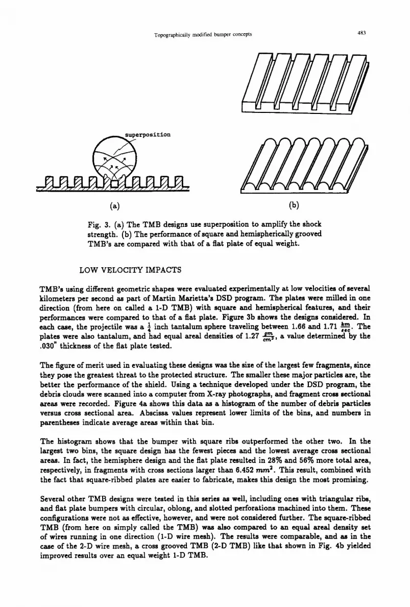
A Topographically Modified Bumper (TMB) is a single layer, ridged, continuous sheet bumper that is capable of providing more protection than an equal weight flat plate bumper. Its effectiveness as a shield is based on the principle of superposition of shock waves that are initiated in the projectile at the location of each impacted rib. Figure 3a illustrates this principle using square ribbing and a spherical projectile. The waves propagate across the sphere as before, but superposition amplifies the pressure as the waves overlap. The result is an increase in temperature and a greater chance of multiple spalling at the rear surface.
Another advantage of TMB's over fiat plate bumpers is that, like the mesh layer of the MDB, it can be rolled for storage and deployed as a shield augmentation layer. Unlike the mesh, however, a TMB with ribs in only one direction can provide structural support in the direction of the ribs.
Finally, by having a continuous backing sheet, the TMB can protect subsequent shielding or insulating layers that might be sensitive to the incidence of atomic oxygen, dust, or radiation. For example, LDEF demonstrated that graphite epoxy, a material which has demonstrated improved MDB performance when used in place of aluminum as the second sheet, could be substantially eroded by atomic oxygen (See et al., 1990). Thus, TMB bumpers are designed to enhance the performance of single flat sheet bumper shields, or can be used as the first layer in a Multi-Shock or MDB-type design to increase debris dispersion.
Topographically modified bumper concepts 483
(a) (b)
Fig. 3. (a) The TMB designs use superposition to amplify the shock strength. (b) The performance of square and hemispherically grooved TMB's are compared with that of a fiat plate of equal weight.
LOW VELOCITY IMPACTS
TMB's using different geometric shapes were evaluated experimentally at low velocities of several kilometers per second as part of Martin Marietta's DSD program. The plates were milled in one direction (from here on called a 1-D TMB) with square and hemispherical features, and their performances were compared to that of a fiat plate. Figure 3b shows the designs considered. In each case, the projectile was a ¼ inch tantalum sphere traveling between 1.66 and 1.71 ~-~c'i'n The plates were also tantalum, and had equal areal densities of 1.27 ~----~, a value determined by the .030" thickness of the fiat plate tested.
The figure of merit used in evaluating these designs was the size of the largest few fragments, since they pose the greatest threat to the protected structure. The smaller these major particles are, the better the performance of the shield. Using a technique developed under the DSD program, the debris clouds were scanned into a computer from X-ray photographs, and fragment cross sectional areas were recorded. Figure 4a shows this data as a histogram of the number of debris particles versus cross sectional area. Abscissa values represent lower limits of the bins, and numbers in parentheses indicate average areas within that bin.
The histogram shows that the bumper with square ribs outperformed the other two. In the largest two bins, the square design has the fewest pieces and the lowest average cross sectional areas. In fact, the hemisphere design and the fiat plate resulted in 28% and 56% more total area, respectively, in fragments with cross sections larger than 6.452 mm 2. This result, combined with the fact that square-ribbed plates are easier to fabricate, makes this design the most promising.
Several other TMB designs were tested in this series as well, including ones with triangular fibs, and fiat plate bumpers with circular, oblong, and slotted perforations machined into them. These configurations were not as effective, however, and were not considered further. The square-ribbed TMB (from here on simply called the TMB) was also compared to an equal areal density set of wires running in one direction (1-D wire mesh). The results were comparable, and as in the case of the 2-D wire mesh, a cross grooved TMB (2-D TMB) like that shown in Fig. 4b yielded improved results over an equal weight 1-D TMB.

4~4 I ' . 1). M,~.( I ".; t ' t L;/.
so
40
30
10
0 0.064S2 0.3226 0.6452 3.226 8.452 32.2
2 Area. rnm
(a) (b)
Fig. 4. Ca) The square ribbed TMB is the most effective at reducing the size and number of the largest fragments. (b) Milling grooves in two directions increases the ei~iciency of the TMB.
MID-RANGE VELOCITY IMPACTS
Only a few shots have been performed on TMB's thus far at velocities higher than several kilo- meters per second. Two shots were performed by JSC/HIRL with a I-D aluminum TMB in place of the wire mesh in a full Mesh Double-Bumper shield. The projectile was a ~ inch aluminum
sphere which impacted at .2~-~ c. The original mesh's .051~----q~ areal density was maintained for the TMB, although the height and width of the ribs differed for the two tests. The rib frequency was set to three ribs per projectile diameter for both shots.
The post-shot inspection revealed back plate penetrations in both TMB shots, while the original wire mesh MDB survived the impact. This difference is thought to be at least in part due to the fact that the TMB had not yet been optimized, and that it was only milled in one direction. Additional tests currently are being planned to help identify optimizing trends and evaluate the effectiveness of a cross-grooved TMB in this configuration. The I-D TMB and 1-D wire mesh were compared again in shots made at these mid-range velocities, and, as at the lower velocities, were found to behave similarly. A significant advantage to the 1-D TMB determined by the tests was that it sustained much less damage (e.g. smaller hole size) than its wire mesh counterpart, thereby better maintaining its protective capability for subsequent debris encounters.
HIGH VELOCITY IMPACTS
Experimental testing at velocities more typical of orbital encounters was not pomible, so numerical simulation with the CTH hydrocode is relied on for a high velocity study. Because of computer limitations, only single plate simulations could be run, and the evaluation of shield performances is based on debris cloud characteristics behind the bumper. Using CTH, the effect of varying the rib he:.zht (H), width (D), and spacing (L), as well as the backing plate thickness iT), is investigated. In all cases, the threat is taken to be a 6.35 mm (¼ in) diarneter (d) aluminum sphere traveling
k m at 10 ~-~c" All shields are assumed to be aluminum, and the point of impact is centered between two ribs in each simulation. The baseline fiat plate used for performance comparison is 1.27 mm
gr~ (.050 in) thick, so all bumpers have an areal density of . 3 4 ~ .

Topographically modified bumper concepts 485
H - - - 1 .524
0 - - - 0 . 6 3 5
L - - - 1.27
T - - - 0 . 5 0 8
H / T - - - 3
H I D - - - 2 .4
d / L - - - 5
H * T - - - 2 . 0 3 2
i
% %
Ca) Cb)
Fig. 5. (s) Rib height, width, spacing, and backing thickness are defined for the nominal configuration. (b) The effect of varying // H i~, and ~ , are investigated for optimization.
Figure 5a defines the various dimensions mentioned above, and gives their values for the nominal TMB configuration. Also given are the initial values of the three variables being considered for the parametric study: ~ , ~ , and d. Esck ratio is varied twice, once higher and once lower than the nominal value, while holding the uninvolved dimensions constant. (Unfortunately, the ratios are coupled, so changing one changes another.) Thus, eight CTH runs are needed for the study. Runs one and two are the fiat plate and nominal TMB, respectively, and dimensions for runs three through eight are given in Table 1. Figure 5b qualitatively shows how the parameter variations affect the TMB.
Table i: Parameter Variation Matrix For CTH Runs
Run H S ~ Z H D L T
1 N/A N/A N/A 0 0 0 1.27 2 3.0 2.4 5.0 1.52 0.63 1.27 0.51 3 1.0 1.3 5.0 0.85 0.63 1.27 0.85 4 5.0 2.9 5.0 1.81 0.63 1.27 0.36 5 1.9 1.0 5.0 0.98 0.98 1.27 0.51 6 4.2 4.8 5.0 2.15 0.45 1.27 0.51 7 3.0 1.4 3.0 1.52 1.06 2.12 0.51 8 3.0 3.4 7.0 1.52 0.45 0.91 0.51
All of the simulations are run in the two dimensional, axis-symmetric formulation. The authors are aware that slight elongation and other minor non-physical irregularities can occur along the symmetry axis using this formulation because of the imposition of artificial boundary conditions, but no serious problems axe encountered in this study.
The fiat plate simulation at three microseconds after impact is pictured in Fig. 6. The shape of the debris cloud is not surprising, and a spall on the verge of detaching from the back of the
. . . . . .
t- J I
4L
t I ) " , 1 ~,, F , ,~ < , , /
F - . . . . . . . . W . . . . . . . - - r . . . . . . . ~ . . . . . . . . . . T . . . . . . . . . . . " i - - -
Temperature ( K )
1800 - 2 7 4 0
E O
>-
-2
/
9 3 3 - 1 8 0 0
< 933
I I I I I I [
~ 0 2 4
X (,m)
Density (gm/cm 3)
[] .0068
[] .014
[] .027
[] .054
.Ii
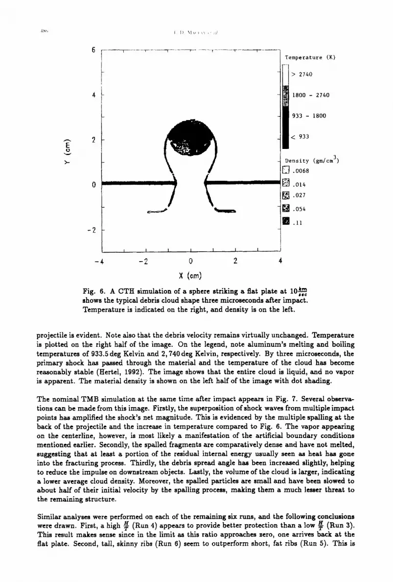
Fig. 6. A CTH simulation of a sphere striking a fiat plate at 10 #~-~ i S =
shows the typical debris cloud shape three microseconds after impact. Temperature is indicated on the right, and density is on the left.
projectile is evident. Note also that the debris velocity remains virtually unchanged. Temperature is plotted on the right half of the image. On the legend, note aluminum's melting and boiling temperatures of 933.5 deg Kelvin and 2,740 deg Kelvin, respectively. By three microseconds, the primary shock has passed through the material and the temperature of the cloud has become reasonably stable (Hertel, 1992). The image shows that the entire cloud is liquid, and no vapor is apparent. The material density is shown on the left half of the image with dot shading.
The nominal TMB simulation at the same time after impact appears in Fig. 7. Several observa- tions can be made from this image. Firstly, the superposition of shock waves from multiple impact points has amplified the shock's net magnitude. This is evidenced by the multiple spalling at the back of the projectile and the increase in temperature compared to Fig. 6. The vapor appearing on the centerline, however, is most likely a manifestation of the artificial boundary conditions mentioned earlier. Secondly, the spalled fragments are comparatively dense and have not melted, suggesting that at least a portion of the residual internal energy usually seen as heat has gone into the fracturing process. Thirdly, the debris spread angle has been increased slightly, helping to reduce the impulse on downstream objects. Lastly, the volume of the cloud is larger, indicating a lower average cloud density. Moreover, the spalled particles are small and have been slowed to about half of their initial velocity by the spalling process, making them a much lesser threat to the remaining structure.
Similar analyses were performed on each of the remaining six runs, and the following conclusions were drawn. First, a high ~ (Run 4) appears to provide better protection than a low ~ (Run 3). This result makes sense since in the limit as this ratio approaches zero, one arrives back at the fiat plate. Second, tall, skinny ribs (Run 6) seem to outperform short, fat ribs (Run 5). This is

Topographically modified bumper concepts 487
E o
4
0
-2
t I I I | I I
I I I I I
- 4 -2 0 2 4
x (0m)
I I
Tempera tu re (K)
> 2740
1800 - 2740
933 - 1800
< 933
D e n s i t y (gm/cm 3)
[ ] ,0068
[ ] .014
[ ] .027
[] .054
[] .II
Fig. 7. At three microseconds, a CTH simulation of a sphere striking km the nominal TMB at 10;;; shows multiple spalling and increased
temperatures due to the superposition of shock waves. Temperature is indicated on the right, and density is on the left.
also not surprising, for the same reason. Last, fewer ribs per projectile diameter (Run 7) appear better than more (Run 8). This is a little less obvious, but again can be explained by considering limiting cases. As the rib width approaches the projectile diameter, the impacting object sees a plate of thickness H + T (assuming it is unlucky enough to have hit the rib!). At the other extreme, as rib width approaches zero, the projectile sees a plate with two different densities. The backing plate remains at the original density but only has thickness T. The ribs, on the other hand, are nothing more than tightly spaced filaments which are seen by the projectile as a solid, but less dense layer of thickness H. Hence, the shock is reduced in this latter case, as are debris spread and temperature.
The most effective of the eight runs is Run 7. The image of its debris cloud is given in Fig. 8. Of primary interest and importance is the debris spread. At three microseconds, the cloud from Run 7 is nearly 50% wider than the cloud from Run 1, and almost 28% wider than the cloud from Run 2. Additionally, there is more spalled material, and more debris mass at higher temperatures (not obvious from the images).
It should be noted that these evaluations are based on single plate simulations, and are subject to some interpretation. For example, some evidence of debris chanelling between the ribs exists, and this may temper or even override the advantages outlined above. To verify that the conclusions drawn here are accurate, simulations should be run with a witness plate so the actual damage to a secondary structure could be directly observed. Unfortunately, these runs are quite CPU intensive, and only a limited number can be made. Runs 1 and 2 were rerun as two-plate problems by inserting a 5 mm witness plate 6.5 cm behind the bumper. Neither witness plate failed, but

I I I I l
Temperature (K)
i > 2 7 4 0
1 8 0 0 - 2 7 4 0
933 - 1800
E o ,. ~. . . . ",," ,,,r, +'+
¢"~D .''~
I < 933
Density (gm/cm 3)
.0068
[] .014
[] .027
[].054
[] .ii
-2 t_ i I i i J i i I
-,+ - 2 0 2 +
x
Fig. 8. At three microseconds, an image of Run 7 shows multiple spalling, increased temperatures, and the largest lateral spread found in any of the runs. Temperature is indicated on the right, and density is on the left.
the dent in the plate in Run 1 was larger than in Run 2. While not much information was revealed by these particular two-plate simulations, additional runs and experimental testing at higher velocities can provide the needed data.
CONCLUSIONS
It has been shown that, throughout the entire velocity range expected during on-orbit debris interactions, a bumper plate with geometric patterns milled into its front surface ai~ords more protection than a fiat plate of equal weight. Through experiment, the 1-D TMB has proven to be comparable to a 1-D row of wires of equal weight, and the 2-D TMB of equal weight has shown additional improvement. In comparing the I-D TMB to the wire mesh, it was found that smaller hole sizes resulted in the TMB, offering better protection against local second strikes. It has been demonstrated through numerical simulation that for a given threat, the TMB can be optim/zed by varying its configuration. It appears that increasing ~ and ~, and decreasing ~ from the nominal values results in a more effective design.
In addition to shielding against impact, TMB's can contribute as a structural member of a wall and offer atomic oxygen, dust, and radiation protection for vulnerable materials.
Additional testing and numerical simulation would be useful to help better quantify the results presented here. This would also aid in the identification of performance trends as a function of threat variations such as debris size, shape, obliquity, and density.

Topographically modified bumper concepts 489
ACKNOWLEDGEMENTS
The authors would like to thank Eugene Hertel from Sandia National Laboratories for supplying the CTH computer code and corresponding technical support, Kelly Leutkemeyer from the Uni- versity of Colorado for his technical and graphics support regarding CTH, and Dr. Pete Snow from Kaman Sciences and John Gassner from Foster Miller for assistance with TMB design de- velopment. The authors are also indebted to Andrew Piekutowski from the University of Dayton Research Institute and Eric Christiansen from the Johnson Space Center for their experimental contributions.
This research is supported in part by the Strategic Defense Initiative Organization, (SDIO/TN) under Martin Marietta's DSD program, by the United States Space Command, Center for Aerospace Analysis under IPA agreements, by the Air Force Armament Laboratory, Eglin AFB, under Award No. F 08635-89-K-0227, by the Martin Marietta Corporation under Contract No.'s 9-040021 and GS0-660111, and by the NASA Johnson Space Center under NASA Grant NAG 9-407 Basic. The research is conducted in part using the facilities of the Colorado Center for As- trodynamics Research and the Department of Aerospace Engineering Sciences at the University of Colorado, Boulder.
REFERENCES
Anderson Jr., C.E., Trucano, T.G., and Mullin, S.A. (1990). Debris Cloud Dynamics. Int. Journal of Impact Engineering, Vol. 9, No. 1, pp. 89-113.
Chhabildas, L.C., and Hertel, E.S. (1991). Experimental and Numerical Simulations of Orbital Debris Impact on a Simple Whipple Bumper Shield. Workshop on Hypervelocity Impacts in Space, University of Canterbury at Kent.
Christiansen, E.L. (1990). Advanced Meteoroid and Debris Shielding Concepts. Paper AIAA 90- 1336, AIAA/NASA/DOD Orbital Debris Conference: Technical Issues and Puture Directions, Baltimore, MD.
Cour-Palais, B.G., and Crews, J.L. (1990). A Multi-Shock Concept for Spacecraft Shielding. Int. Journal of Impact Engineering, Vol. 10, pp. 135-146.
Crews, J.L., and Christiansen, E.L. (1992). The NASA JSC Hypervelocity Impact Test Fa- cility (HIT-F). Paper AIAA 92-1640, AIAA Space Programs and Technologies Conference, Huntsville, AL.
Hertel, E.S., Chhabildas, L.C., and Yarrington, L. (1991). Computational Determination of Ballistic Limits for a Simple Whipple Bumper Shield. Workshop on Hypervelocity Impacts in Space, University of Canterbury st Kent.
Hertel, E.S. (1992). Personal communication. Maclay, T.D., Madler, R.A., McNamara, R., and Culp, R.D. (1991). Orbital Debris Hazard Anal-
ysis for Long-Term Space Assets. Workshop on Hypervelocity Impacts in Space, University of Canterbury at Kent.
McKnight, D. (1991). Space Shuttle Performs Maneuver to Avoid Debris. Orbital Debris Monitor, Vol. 4, No. 4, p. 3.
Morrison, R.H. (1972). A Preliminary Investigation of Projectile Shape Effects in Hypervelocity Impact of a Double-Sheet Structure. NASA TN D-6944, Ames Research Center, Moffett Field, CA.
Piekutowski, A.J. (1987). Debris Clouds Generated by Hypervelocity Impact of Cylindrical Pro- jectiles with Thin Aluminum Plates. Int. Journal of Impact Engineering, Vol. 5, No. 1, pp. 509-518.
See, T., Allbrooks, M., Atkinson, D., Simon, C., and Zolensky, M. (1990). Meteoroid and De- bris Impact Features Documented On The Long Duration Exposure Facility: A Preliminary Report. NASA Pub. No. 84, JSC No. 24608.
Whipple, F.L. (1947). Meteorites and Space Travel. The Astronomical Jo~rn,d, Vol. 52, No. 1161, p. 131.


