Embed Size (px)
Citation preview
TOUCH SCREEN
K8046
ILLUSTRATED ASSEMBLY MANUAL H8046IP-2
Total solder points: 274 Difficulty level: beginner 1 2 3 4 5 advanced
Create your own keyboard with your
personal layout & symbols.


3
CAUTION:
This kit is supplied with a GLASS type keyboard. BE VERY GENTLE WITH THIS TYPE OF
KEYBOARD, THE SLIGHTEST BENDING WILL BREAK THE GLASS AND COULD CAUSE INJURY.
A BROKEN KEYBOARD IS NOT COVERED BY THE
WARRANTY, A NEW KEYBOARD CAN BE ORDERED AT YOUR DEALER. ORDER CODE: KB020501
IMPORTANT: Since this is a complex assembly with a lot of possibilities, it is advisable to
read through the complete instructions BEFORE starting the actual assembly. BE WARNED !
!
4
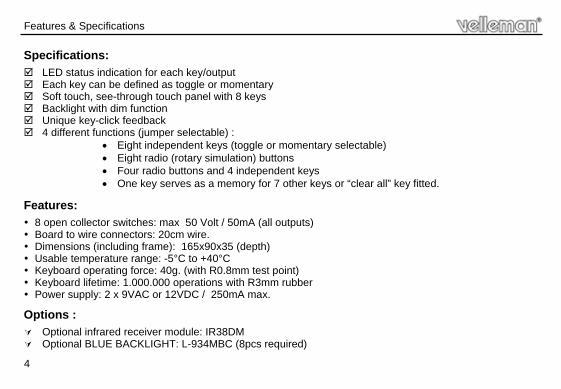
Specifications:
LED status indication for each key/output Each key can be defined as toggle or momentary Soft touch, see-through touch panel with 8 keys Backlight with dim function Unique key-click feedback 4 different functions (jumper selectable) :
• Eight independent keys (toggle or momentary selectable) • Eight radio (rotary simulation) buttons • Four radio buttons and 4 independent keys • One key serves as a memory for 7 other keys or “clear all” key fitted.
Features:
8 open collector switches: max 50 Volt / 50mA (all outputs) Board to wire connectors: 20cm wire. Dimensions (including frame): 165x90x35 (depth) Usable temperature range: -5°C to +40°C Keyboard operating force: 40g. (with R0.8mm test point) Keyboard lifetime: 1.000.000 operations with R3mm rubber Power supply: 2 x 9VAC or 12VDC / 250mA max.
Options :
Optional infrared receiver module: IR38DM Optional BLUE BACKLIGHT: L-934MBC (8pcs required)
Features & Specifications

5
Assembly hints
1. Assembly (Skipping this can lead to troubles ! ) Ok, so we have your attention. These hints will help you to make this project successful. Read them carefully. 1.1 Make sure you have the right tools: • A good quality soldering iron (25-40W) with a small tip.
• Wipe it often on a wet sponge or cloth, to keep it clean; then apply solder to the tip, to give it a wet look. This is called ‘thinning’ and will protect the tip, and enables you to make good connections. When solder rolls off the tip, it needs cleaning.
• Thin raisin-core solder. Do not use any flux or grease.
• A diagonal cutter to trim excess wires. To avoid injury when cutting excess leads, hold the lead so they cannot fly towards the eyes.
• Needle nose pliers, for bending leads, or to hold components in place.
• Small blade and Phillips screwdrivers. A basic range is fine.
For some projects, a basic multi-meter is required, or might be handy
1.2 Assembly Hints :
⇒ Make sure the skill level matches your experience, to avoid disappointments. ⇒ Follow the instructions carefully. Read and understand the entire step before you perform each operation. ⇒ Perform the assembly in the correct order as stated in this manual ⇒ Position all parts on the PCB (Printed Circuit Board) as shown on the drawings. ⇒ Values on the circuit diagram are subject to changes. ⇒ Values in this assembly guide are correct* ⇒ Use the check-boxes to mark your progress. ⇒ Please read the included information on safety and customer service
* Typographical inaccuracies excluded. Always look for possible last minute manual updates, indicated as ‘NOTE’ on a separate leaflet.
0.000

6
Assembly hints
1.3 Soldering Hints :
1- Mount the component against the PCB surface and carefully solder the leads
2- Make sure the solder joints are cone-shaped and shiny
3- Trim excess leads as close as possible to the solder joint
REMOVE THEM FROM THE TAPE ONE AT A TIME !
AXIAL COMPONENTS ARE TAPED IN THE COR-RECT MOUNTING SEQUENCE !
7
Construction
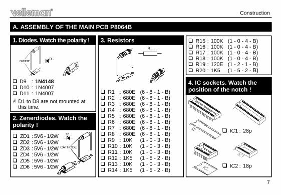
D9 : 1N4148 D10 : 1N4007 D11 : 1N4007
D1 to D8 are not mounted at this time.
1. Diodes. Watch the polarity !
D...CATHODE
ZD1 : 5V6 - 1/2W ZD2 : 5V6 - 1/2W ZD3 : 5V6 - 1/2W ZD4 : 5V6 - 1/2W ZD5 : 5V6 - 1/2W ZD6 : 5V6 - 1/2W
2. Zenerdiodes. Watch the polarity !
CATHODE
ZD...
R1 : 680E (6 - 8 - 1 - B) R2 : 680E (6 - 8 - 1 - B) R3 : 680E (6 - 8 - 1 - B) R4 : 680E (6 - 8 - 1 - B) R5 : 680E (6 - 8 - 1 - B) R6 : 680E (6 - 8 - 1 - B) R7 : 680E (6 - 8 - 1 - B) R8 : 680E (6 - 8 - 1 - B) R9 : 10K (1 - 0 - 3 - B) R10 : 10K (1 - 0 - 3 - B) R11 : 10K (1 - 0 - 3 - B) R12 : 1K5 (1 - 5 - 2 - B) R13 : 10K (1 - 0 - 3 - B) R14 : 1K5 (1 - 5 - 2 - B)
A. ASSEMBLY OF THE MAIN PCB P8064B
3. Resistors R...
R15 : 100K (1 - 0 - 4 - B) R16 : 100K (1 - 0 - 4 - B) R17 : 100K (1 - 0 - 4 - B) R18 : 100K (1 - 0 - 4 - B) R19 : 120E (1 - 2 - 1 - B) R20 : 1K5 (1 - 5 - 2 - B)
IC1 : 28p
IC2 : 18p
4. IC sockets. Watch the position of the notch !
8
Construction
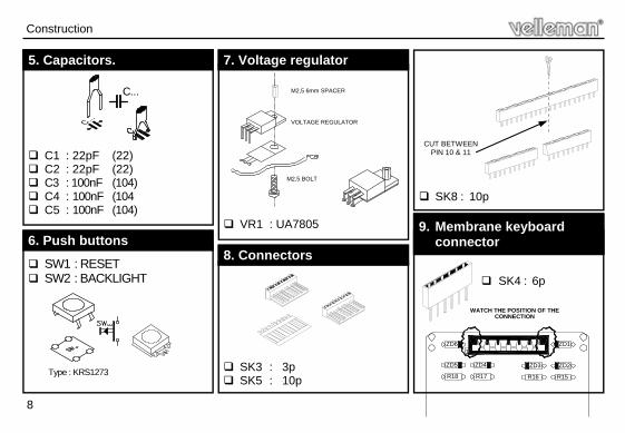
C1 : 22pF (22) C2 : 22pF (22) C3 : 100nF (104) C4 : 100nF (104 C5 : 100nF (104)
5. Capacitors.
C...
SW1 : RESET SW2 : BACKLIGHT
Type : KRS1273
6. Push buttons
VR1 : UA7805
7. Voltage regulator
M2.5 SPACER
SK3 : 3p SK5 : 10p
8. Connectors
SK8 : 10p
CUT BETWEEN PIN 10 & 11
SK4 : 6p
9. Membrane keyboard connector
ZD6
ZD5
R18 R17
ZD4 ZD3
R16 R15
ZD2
ZD11
VOLTAGE REGULATOR
M2,5 BOLT
WATCH THE POSITION OF THE CONNECTION
M2,5 6mm SPACER
9
Construction
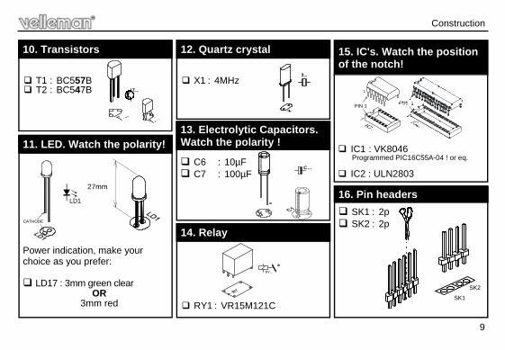
C6 : 10µF C7 : 100µF
13. Electrolytic Capacitors. Watch the polarity !
SK1 : 2p SK2 : 2p
16. Pin headers
T1 : BC557B T2 : BC547B
10. Transistors
C...
Power indication, make your choice as you prefer: LD17 : 3mm green clear
OR 3mm red
11. LED. Watch the polarity!
LD1
CATHODE
X1 : 4MHz
12. Quartz crystal
X...
RY1 : VR15M121C
14. Relay
RY...
15. IC's. Watch the position of the notch!
IC1 : VK8046 Programmed PIC16C55A-04 ! or eq. IC2 : ULN2803
PIN 1
1
SK1
SK2
27mm
10
Keyboard set-up
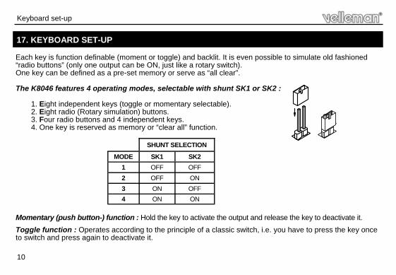
Each key is function definable (moment or toggle) and backlit. It is even possible to simulate old fashioned “radio buttons” (only one output can be ON, just like a rotary switch). One key can be defined as a pre-set memory or serve as “all clear”. The K8046 features 4 operating modes, selectable with shunt SK1 or SK2 :
1. Eight independent keys (toggle or momentary selectable). 2. Eight radio (Rotary simulation) buttons. 3. Four radio buttons and 4 independent keys. 4. One key is reserved as memory or “clear all” function.
Momentary (push button-) function : Hold the key to activate the output and release the key to deactivate it.
Toggle function : Operates according to the principle of a classic switch, i.e. you have to press the key once to switch and press again to deactivate it.
17. KEYBOARD SET-UP
MODE SK1 SK2 1 OFF OFF 2 OFF ON 3 ON OFF 4 ON ON
SHUNT SELECTION
11
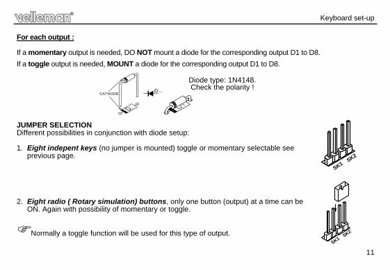
For each output : If a momentary output is needed, DO NOT mount a diode for the corresponding output D1 to D8.
If a toggle output is needed, MOUNT a diode for the corresponding output D1 to D8.
JUMPER SELECTION Different possibilities in conjunction with diode setup: 1. Eight indepent keys (no jumper is mounted) toggle or momentary selectable see
previous page. 2. Eight radio ( Rotary simulation) buttons, only one button (output) at a time can be
ON. Again with possibility of momentary or toggle.
Normally a toggle function will be used for this type of output.
Keyboard set-up
D...CATHODE
Diode type: 1N4148. Check the polarity !
SK2
SK1
SK1SK2
12
Keyboard set-up
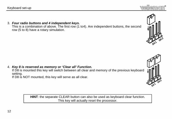
3. Four radio buttons and 4 independent keys.
This is a combination of above. The first row (1 to4). Are independent buttons, the second row (5 to 8) have a rotary simulation.
4. Key 8 is reserved as memory or ‘Clear all’ Function.
If D8 is mounted this key will switch between all clear and memory of the previous keyboard setting. If D8 is NOT mounted, this key will serve as all clear.
SK1SK2
SK1SK2
HINT: the separate CLEAR button can also be used as keyboard clear function. This key will actually reset the processor.
13
IR detector
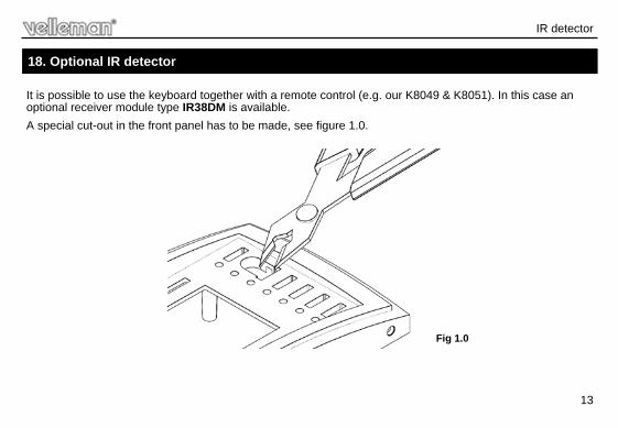
It is possible to use the keyboard together with a remote control (e.g. our K8049 & K8051). In this case an optional receiver module type IR38DM is available.
A special cut-out in the front panel has to be made, see figure 1.0.
18. Optional IR detector
Fig 1.0
14
3
Fig 2.0
2 1
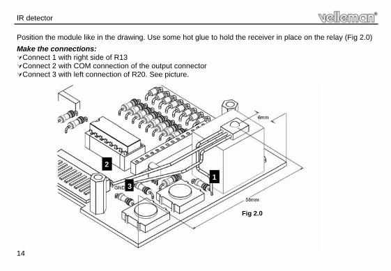
Position the module like in the drawing. Use some hot glue to hold the receiver in place on the relay (Fig 2.0)
Make the connections: Connect 1 with right side of R13 Connect 2 with COM connection of the output connector Connect 3 with left connection of R20. See picture.
IR detector
15
2. Spacers for keyboard support
Construction
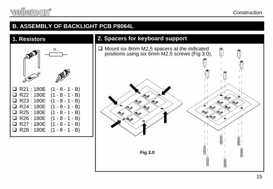
R21 : 180E (1 - 8 - 1 - B) R22 : 180E (1 - 8 - 1 - B) R23 : 180E (1 - 8 - 1 - B) R24 : 180E (1 - 8 - 1 - B) R25 : 180E (1 - 8 - 1 - B) R26 : 180E (1 - 8 - 1 - B) R27 : 180E (1 - 8 - 1 - B) R28 : 180E (1 - 8 - 1 - B)
B. ASSEMBLY OF BACKLIGHT PCB P8064L
1. Resistors
R...
Fig 3.0
Mount six 8mm M2,5 spacers at the indicated positions using six 6mm M2,5 screws (Fig 3.0).
16
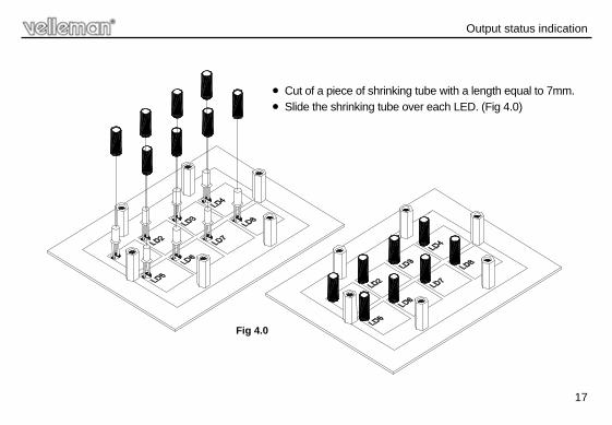
Output status indication
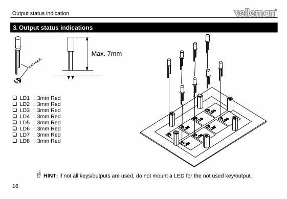
LD1 : 3mm Red LD2 : 3mm Red LD3 : 3mm Red LD4 : 3mm Red LD5 : 3mm Red LD6 : 3mm Red LD7 : 3mm Red LD8 : 3mm Red
3. Output status indications
Max. 7mm
HINT: if not all keys/outputs are used, do not mount a LED for the not used key/output.
17
• Cut of a piece of shrinking tube with a length equal to 7mm. • Slide the shrinking tube over each LED. (Fig 4.0)
Fig 4.0
Output status indication
18
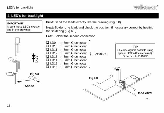
LED’s for backlight
IMPORTANT Mount these LED’s exactly like in the drawings.
4. LED's for backlight
LD...
Anode
L-934GC
First: Bend the leads exactly like the drawing (Fig 5.0).
Next: Solder one lead, and check the position, if necessary correct by heating the soldering (Fig 6.0).
Last: Solder the second connection. LD9 : 3mm Green clear LD10 : 3mm Green clear LD11 : 3mm Green clear LD12 : 3mm Green clear LD13 : 3mm Green clear LD14 : 3mm Green clear LD15 : 3mm Green clear LD16 : 3mm Green clear
MAX. 7mm
MAX 7mm!
Fig 6.0
TIP Blue backlight is possible using special LED’s (8pcs required).
Ordernr. : L-934MBC
Fig 5.0
19
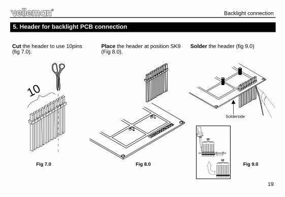
Backlight connection
5. Header for backlight PCB connection
10
Fig 7.0 Fig 8.0 10!
10!
Fig 9.0
Place the header at position SK9 (Fig 8.0).
Cut the header to use 10pins (fig 7.0).
Solder the header (fig 9.0)
Solderside
20
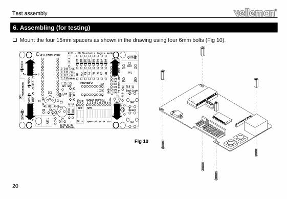
Test assembly
Mount the four 15mm spacers as shown in the drawing using four 6mm bolts (Fig 10).
6. Assembling (for testing)
Fig 10
21
Test assembly
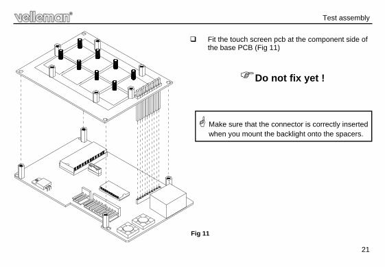
Fit the touch screen pcb at the component side of the base PCB (Fig 11)
Do not fix yet !
Make sure that the connector is correctly inserted when you mount the backlight onto the spacers.
Fig 11
22
Testing the circuit
A
B
1
2
3
4
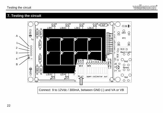
Connect 9 to 12Vdc / 300mA, between GND (-) and VA or VB
7. Testing the circuit
23
Before making a final assembly we will test the circuit: Supply the power to the circuit (use the supplied wired connector, brown (-) and red (+) wire).
Normally the relay should “click” and the backlight should lit. If not; try “reset” SW1. Now test the keyboard input (keyboard connector SK4): Using a small piece of wire, make a shunt between point A and point 1, one of the output LED’s should lit. Now test the other points A+2, A+3 and A+4. All the top row output LED’s should have lit one by one. Perform the same test using point B as common, all the bottom row output LED’s should lit one by one.
The circuit is now ready for final assembly.
REMOVE THE BACKLIGHT PCB !
Testing the circuit
24
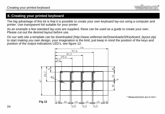
The big advantage of this kit is that it is possible to create your own keyboard lay-out using a computer and printer. Use transparent foil suitable for your printer
As an example a few standard lay-outs are supplied, these can be used as a guide to create your own. Please cut-out the desired layout before use.
On our web site a template can be downloaded (http://www.velleman.be/Downloads/0/Keyboard_layout.zip) to start making you own design, your imagination is the limit, just keep in mind the position of the keys and position of the output indications LED’s, see figure 12.
8. Creating your printed keyboard
* Measurements are in mm !
Fig 12
Creating your printed keyboard
25
Mounting order
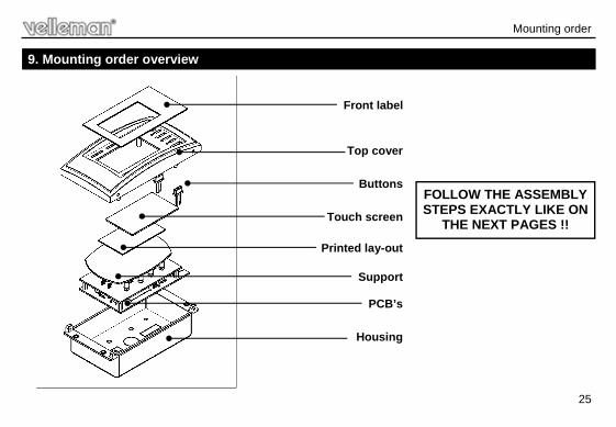
9. Mounting order overview
Printed lay-out
Housing
PCB’s
Support
Touch screen
Buttons
Top cover
Front label
FOLLOW THE ASSEMBLY STEPS EXACTLY LIKE ON
THE NEXT PAGES !!
26
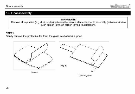
IMPORTANT: Remove all impurities (e.g. dust, solder) between the various elements prior to assembly (between window
& on-screen keys, on-screen keys & touchscreen).
10. Final assembly
Final assembly
STEP1 Gently remove the protective foil form the glass keyboard & support
Fig 13
Support
Glass keyboard
27
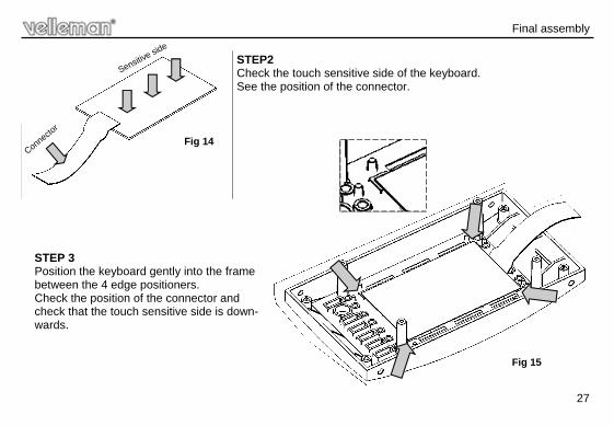
Connector
Sensitive side
STEP2 Check the touch sensitive side of the keyboard. See the position of the connector.
Fig 14
STEP 3 Position the keyboard gently into the frame between the 4 edge positioners. Check the position of the connector and check that the touch sensitive side is down-wards.
Final assembly
Fig 15
28
Final assembly
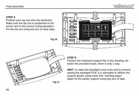
STEP 4 Position your lay-out onto the keyboard. Make sure the lay-out is positioned in the centre and in the correct surface/position. Fix the lay-out using two pcs of clear tape.
STEP 5 Position the keyboard support like in the drawing, be-tween the provided studs, there is only 1 way. HINT: to make the backlight more even and to prevent seeing the backlight PCB, it is advisable to diffuse the support plastic using some fine “sanding paper” Again fix the plastic support using two pcs of tape.
Fig 16
Fig 17
29
Final assembly
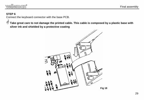
STEP 6 Connect the keyboard connector with the base PCB.
Take great care to not damage the printed cable. This cable is composed by a plastic base with silver ink and shielded by a protective coating
Fig 18
30
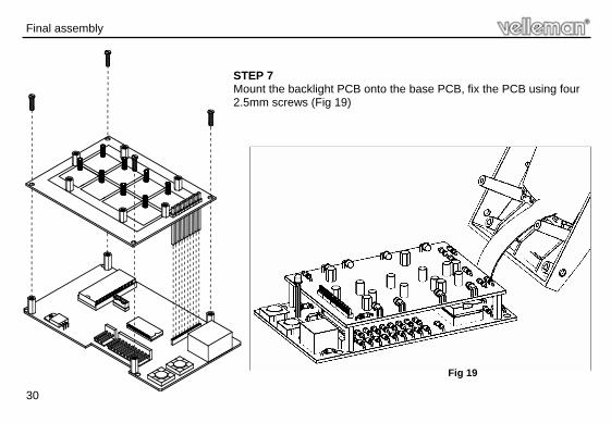
STEP 7 Mount the backlight PCB onto the base PCB, fix the PCB using four 2.5mm screws (Fig 19)
Fig 19
Final assembly
31
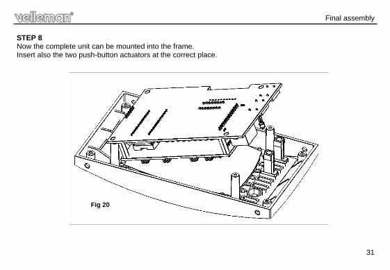
STEP 8 Now the complete unit can be mounted into the frame. Insert also the two push-button actuators at the correct place.
Final assembly
Fig 20
32
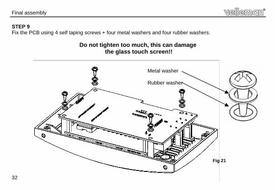
STEP 9 Fix the PCB using 4 self taping screws + four metal washers and four rubber washers.
Do not tighten too much, this can damage the glass touch screen!!
Metal washer Rubber washer
Final assembly
Fig 21
33
Final assembly
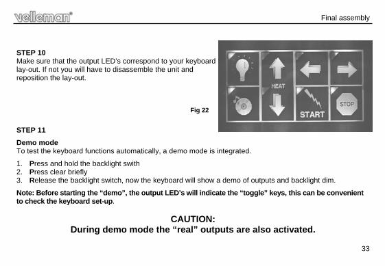
STEP 10 Make sure that the output LED’s correspond to your keyboard lay-out. If not you will have to disassemble the unit and reposition the lay-out.
STEP 11
Demo mode To test the keyboard functions automatically, a demo mode is integrated.
1. Press and hold the backlight swith 2. Press clear briefly 3. Release the backlight switch, now the keyboard will show a demo of outputs and backlight dim.
Note: Before starting the “demo”, the output LED’s will indicate the “toggle” keys, this can be convenient to check the keyboard set-up.
CAUTION: During demo mode the “real” outputs are also activated.
Fig 22
34
Mounting the keyboard
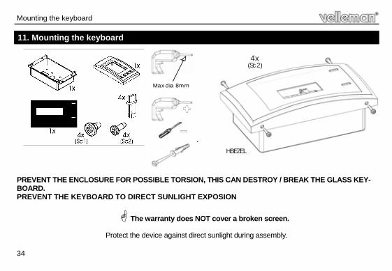
PREVENT THE ENCLOSURE FOR POSSIBLE TORSION, THIS CAN DESTROY / BREAK THE GLASS KEY-BOARD. PREVENT THE KEYBOARD TO DIRECT SUNLIGHT EXPOSION
The warranty does NOT cover a broken screen.
Protect the device against direct sunlight during assembly.
Max dia 8mm
4x(Sc2)
HBEZEL
11. Mounting the keyboard
35
Mounting the keyboard
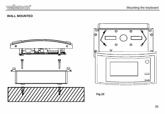
WALL MOUNTED
Fig 23
36
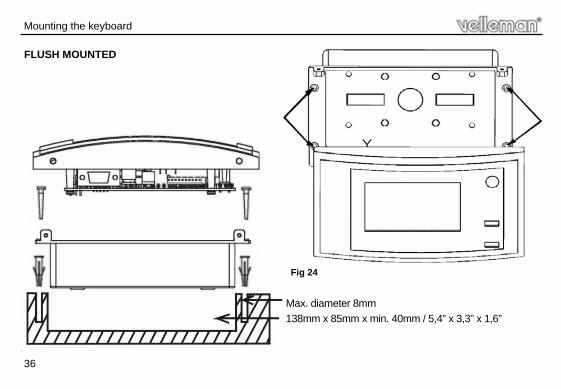
FLUSH MOUNTED
Max. diameter 8mm
138mm x 85mm x min. 40mm / 5,4” x 3,3” x 1,6”
Fig 24
Mounting the keyboard
37
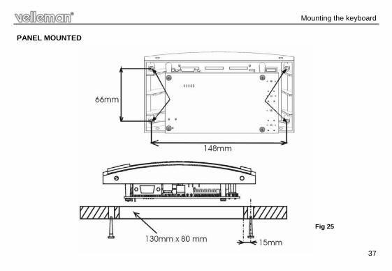
PANEL MOUNTED
Mounting the keyboard
Fig 25
38
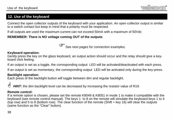
Connect the open collector outputs of the keyboard with your application. An open collector output is similar to a switch contact but keep in mind that a polarity must be respected.
If all outputs are used the maximum current can not exceed 50mA with a maximum of 50Vdc
REMEMBER: There is NO voltage coming OUT of the outputs
See next pages for connection examples.
Keyboard operation: Gently press the key on the glass keyboard, an output action should occur and the relay should give a key-board click feeling.
If an output is set as a toggle, the corresponding output LED will be activated/deactivated with each press.
If an output is set as momentary, the corresponding output LED will be activated only during the key-press.
Backlight operation: Each press of the backlight button will toggle between dim and regular backlight.
HINT: the dim backlight level can be decreased by increasing the resistor value of R19.
Remote control: If a remote option is chosen, please set the remote K8049 & K8051 in mode 1 to make it compatible with the keyboard (see remote control manual). The keys 1 to 8 on the remote will simulate the keyboard keys 1 to 4 (top row) and 5 to 8 (bottom row). The clear function of the remote (Shift + key 16) will clear the outputs (same function as the “Clear” button).
12. Use of the keyboard
Use of the keyboard
39
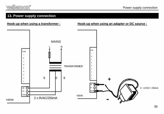
Hook-up when using a transformer : Hook-up when using an adapter or DC source :
8
7
6
5
4
3
2
1
VB
VA
GND
L N
K8046
+
COM
120 - 220 VAC
2 x 9VAC/250mA
Fuse : 250mA T
TRANSFORMER
MAINS
0 9 9
8
7
6
5
4
3
2
1
VB
VA
GND
K8046
+
COM
9 - 12VDC / 250mA
+
-
13. Power supply connection
Power supply connection
40
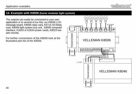
14. Example with K8006 (home modular light system)
Application examples
The outputs can easily be connected to your own application or to several of our kits; our K8045 LCD message board, K8056 relay card, K6714-16 Relay card, K8006 light system bus unit , K8000 computer interface, K2633 or K2634 power cards, K8023 two wire remote. For further connections of the K8006 look at the illustrated part list of the K8006.
24VAC LOAD1N
1
VELLEMAN K8006
LSUPPLY
OPEN
COLL
ECTO
RIN
PUTS
C
LOAD2N LOAD3N LOAD4N LOAD5NN
1 2 3 4 5
DANGER
HIGHVOLTAGE
TRAN
SFO
RM
ER
24VAC
PRIM
2 3 4 5PUSH BUTTON INPUTS
SW1 SW2 SW3 SW4 SW5
TRAN
SFO
RM
ER
2 x 9VAC
PRIM
VELLEMAN K8046
AC POWER
9 0 9
L N
AC POWER
L N
AC POWER
C C C C C
41
Application examples
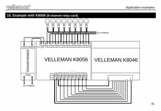
15. Example with K8056 (8-channel relay card)
NO 7
0 - 7SK18
0 +12V
RS2320- INSK10 SK11
V Out
AC 12VINPUT
NO 1 NO 2
0 - 2SK13
0 - 1SK12
0 - 3SK14 SK16
0 - 50 - 4SK15
I N P U T S
0 - 6SK17
NO 3 NO 4 NO 6NO 5
SK1 SK2 SK3 SK4 SK5 SK6 SK7
0 - 8SK19
NO 8
SK9SK8
TRAN
SFO
RM
ER
12VAC/500mA
PRIM
AC POWER
CO
M+ 8 7 6 5 4 3 2 1 VB VA G
ND
VELLEMAN K8046
AC POWER
VELLEMAN K8056
42
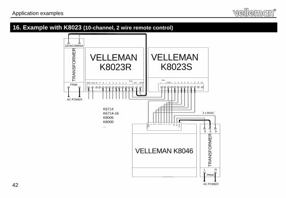
16. Example with K8023 (10-channel, 2 wire remote control)
Application examples
9
VELLEMAN TR
AN
SFO
RM
ER
12VAC/300mA
PRIM
2 x 9VAC
VELLEMAN K8046
AC POWER
10 8 7 6 5 4 3 2 1 - + 12V ... 15VinGND +VextVext
K8023R1
VELLEMAN
COM 2 3 4 5 6 7 8 9 10+ -
K8023SVext
TRA
NS
FOR
ME
R
PRIM
AC POWER
9 0 9
L N
K6714K6714-16K8006K8000...
43
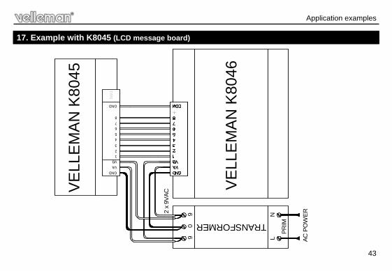
17. Example with K8045 (LCD message board)
Application examples
SW
3
TRANSFORMER
2 x
9VAC
PRIM
VELL
EMAN
K80
46
AC P
OW
ER
90
9
LN
VE
LLE
MAN
K80
45GNDVAVB12345678
GND
44
Application examples
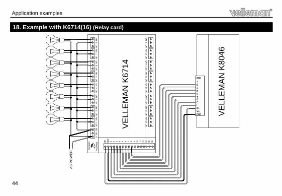
18. Example with K6714(16) (Relay card)
VELL
EMAN
K67
14
VELL
EMAN
K80
46
AC
PO
WE
R
012
522
0NC
1NO
NC2
NONC
3NO
NC4
NONC
5NO
NC6
NONC
7NO
NC8
NO
NC16
NONC
15NO
NC14
NONC
13NO
NC12
NONC
11NO
NC10
NONC
9NO
DAN
GER
HIG
HVO
LTAG
E VB GND 1 2 3 4 5 6 7 8 9 10 11 13 14 15 16
45
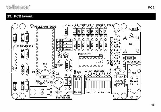
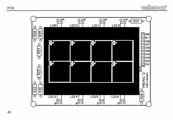
19. PCB layout.
PCB
46
PCB
47
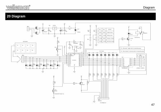
20 Diagram
Title
RA0 6
RA1 7
RA2 8
RA3 9
RB0 10RB1 11RB2 12RB3 13RB4 14RB5 15RB6 16RB7 17
RC018
RC119
RC220
RC321
RC422
RC523
RC624
RC725
VS
S4
MCLR/VPP28
OSC1/CLKIN27
T0CKI1 OSC2/CLKOUT 26
NC3
NC5
VD
D2
PIC16C55
IC1
12345678910
BTWM10 + BTWF10
SK5
123
SK3
IN 11
IN 22
IN 33
IN 44
IN 55
IN 66
IN 77
IN 88
GN
D9
DIODE CLAMP10 OUT 8 11OUT 7 12OUT 6 13OUT 5 14OUT 4 15OUT 3 16OUT 2 17OUT 1 18
ULN2803A(18)
IC2
100n
C3
100nC4
100nC5
100µ/25V
C710µFC6
SK1 SK2
1N4007
D10
1N4007
D11
D8 D7 D6 D5 D4 D3 D2
1N4148
D1
5V6ZD2
5V6ZD3
5V6ZD4
5V6ZD1
5V6ZD5
5V6ZD6
123456
SK4
I O
GND
UA7805VR1
X4.000MHZ
X1
22pC2
22pC1
10KR10
10KR11
10KR9
KRS1243
SW1
KRS1243SW2
10KR13
1K5
R14
+5V
+5V
+5V
+5V
+5V +5V
SK1 SK2
CLOSE
OPEN
OPEN
OPEN
OPEN
CLOSE
CLOSE CLOSE
8 Indep. buttons
8 Rotary switch
4 Rotary + 4 indep.
B4= all off or mem.
ACTION
D1... D8 mounted = toggle mode for corresponding output
D1... D8 not mounted = momentary mode for corresponding output
BACKLIGHT: High / Low
120R19
A1 A2 A3 A4
B1 B2 B3 B4
A4312B
8X
KEYBOARD
A
B
+5V
BC547
T21K5
R12
1N4148D9
+V
Keyclick relay
+V
100KR16
100KR17
100KR15
100KR18
To backlight pcb
+5V
12345678910
96120205SK8
BC557
T1
680R8
680R7
680R6
680R5
680R4
680R3
680R2
680R1
VR3SM121CRY1
680
R20
L-934GC
LD17
Com +Com -
12345678
Ope
n co
llect
or o
utpu
t
Diagram

Modifications and typographical errors reserved © Velleman Components nv. H8046IP - 2005 - ED2
VELLEMAN Components NV Legen Heirweg 33
9890 Gavere Belgium Europe
www.velleman.be www.velleman-kit.com
5 4 1 0 3 2 9 3 4 3 6 2 0


