Embed Size (px)
Citation preview
Transmission two-modulator generalizedellipsometry measurements
Gerald E. Jellison, Jr., C. Owen Griffiths, David E. Holcomb, andChristopher M. Rouleau
The two-modulator generalized ellipsometer has been used to measure samples in transmission. In thisconfiguration, the instrument can completely characterize a linear diattenuator and retarder, measuringbirefringence, diattenuation, the angle of the principal axis, and the sample depolarization simulta-neously and accurately. This instrument can be operated in two modes: �1� spectroscopic, in whichmeasurements are made through the entire sample aperture as a function of wavelength, and �2�spatially resolved, in which measurements are made at a single wavelength and a birefringence pictureis made of the sample. Current spatially resolved measurements have been made at a resolution of �40�m. Four samples have been examined with this instrument: �1� a mica plate, �2� a Polaroid polarizer,and �3� two quartz plates. © 2002 Optical Society of America
OCIS codes: 120.2130, 120.4640, 120.5060, 160.4670.
1. Introduction
Many optical devices affect the polarization state ofthe light beam passing through the device. Suchdevices include simple polarizers that change the in-cident light into a linearly polarized beam and retard-ers that elliptically polarize an incident linearlypolarized light beam. Most devices of this type areconsidered to be either ideal polarizers that containno component of retardation or pure retarders thatexhibit no diattenuation. However, many polariza-tion devices are not ideal; polarizers may also retardthe light beam, and retarders may also contain somediattenuation. These issues are discussed at lengthby Chipman.1
Linear birefringence of materials has been mea-sured in a variety of ways for many years. If thebirefringence is large, it can be measured with thesample placed between crossed polarizers. How-ever, this technique does not measure small retarda-tions accurately, nor can it determine the fast-axis
direction in the material. Early on, Modine and co-workers2 used a single polarizer–photoelastic modu-lator �PEM� pair to measure small values ofbirefringence, although their system could not deter-mine independently the direction of the fast axis.Recently, Wang and Oakberg,3 using another appa-ratus based on a single PEM and a dual-detectorconfiguration, showed that accurate values of the lin-ear birefringence could be determined if its value issmall; in addition, they were able to accurately mea-sure the direction of the fast axis. By scanning theirapparatus over an optic, they obtained a linear bire-fringence and a fast-axis direction map of the optic.
If the optic is neither a pure polarizer nor a pureretarder, then considerably more information isneeded to totally describe it. At a minimum, it isnecessary to measure the diattenuation, the directionof the principal axis, and the signed value of theretardation. It is also advantageous to measure thecircular diattenuation. The complete Mueller ma-trix for a general optic consists of 16 elements �15 ifthe Mueller matrix is normalized to the m11 compo-nent�. For most cases, all 16 �or 15� elements neednot be measured. One technique, described by Az-zam,4 Hauge,5 and Goldstein and Chipman,6,7 usesdual rotating polarizers to measure the completeMueller matrix of a sample. Other researchers8,9
have used standard nulling ellipsometry schemes�polarizer, compensator, sample, analyzer� in trans-mission mode to measure the retardation and otherparameters.
G. E. Jellison, Jr. �[email protected]; Solid State Division�,D. E. Holcomb �Nuclear Science and Technology Division�, andC. M. Rouleau �Solid State Division� are with Oak Ridge NationalLaboratory, Oak Ridge, Tennessee 37831. C. O. Griffiths is withHinds Instruments, Incorporated, Hillsboro, Oregon 97124.
Received 14 February 2002; revised manuscript received 26 July2002.
0003-6935�02�316555-12$15.00�0© 2002 Optical Society of America
1 November 2002 � Vol. 41, No. 31 � APPLIED OPTICS 6555
In this paper we describe an alternative tech-nique to measure the sample birefringence whereboth the polarization-state generator �PSG� andthe polarization-state analyzer �PSA� consist of apolarizer–PEM pair, where the PEMs are con-structed such that they resonate at different frequen-cies �50 and 60 kHz in our case�. This technique issimilar to the two-modulator generalized ellipsom-eter �2-MGE�,10,11 the only difference being that thepresent instrument is operated in transmission. Weshow that this instrument measures sufficient pa-rameters to determine the sample retardation, diat-tenuation, and principal axis angle simultaneously.Furthermore, the accuracy of these measurements,although not as good as those of Ref. 2 for small linearbirefringence, is much greater than many other tech-niques. We can perform 2-MGE transmission ellip-sometry spectroscopically or in a mapping mode, andit has no limitation on the magnitude of the retarda-tion required to make accurate measurements.
2. Theory
A. Mueller Matrix Formulation
The Mueller matrix for a nondepolarizing linear di-attenuator and retarder is given1,12–15 by
M � �1 �N 0 0
�N 1 0 00 0 C S0 0 �S C
� , (1)
where �N is the diattenuation and �S is the circularretardance. The Mueller matrix M of Eq. �1� wasnormalized to the m11 term. This expression is for-mally the same as the expression of an isotropic sam-ple in a reflection ellipsometry experiment,11,15 where
N � cos�2��, (2a)
S � sin�2��sin���, (2b)
C � sin�2��cos���, (2c)
and � and � are the traditional ellipsometry param-eters. For a compensator, the retardation � is givenby
� �2d�n
, (3a)
where d is the thickness of the sample, is the wave-length of light, and �n � no � ne is the refractive-index difference between the ordinary andextraordinary rays. The quantities S and C aregiven by
S � �1 � N 2�sin���, (3b)
C � �1 � N 2�cos���. (3c)
The quantity �N is the signed diattenuation, givenby
N � �Po � Pe
Po � Pe, (3d)
where Po�Pe� is the light power transmitted for lightpolarized along the ordinary �extraordinary� direc-tion. A perfect polarizer will have N � �1, S � C �0, whereas a perfect retarder will have N � 0, � �atan �S�C�.
If the optic does not depolarize the light beam, thenthe N, S, and C parameters are not independent, butare constrained by
N 2 � S2 � C2 � 1. (4a)
If the sample does depolarize the light, then the mea-sured values16 are
Nm2 � Sm
2 � Cm2 � �2 � 1, (4b)
where the subscript m emphasizes that the parame-ters are subject to random and systematic errors aswell as depolarization effects.
For an isotropic ellipsometry sample, the fast axisis defined by the plane of incidence, so it is not pos-sible to physically rotate the sample to change thedirection of the fast axis with respect to the frame ofreference of the instrument. As such, isotropic el-lipsometry samples will always have the off-blockdiagonal elements equal to zero. Anisotropic sam-ples11,17 will generally have cross-polarization effects,normally resulting in the off-block diagonal elementsbeing nonzero �there are some symmetry directionswhere these elements of the sample Mueller matrixwill be zero�. For a linear diattenuator and retarder,however, the principal axis �fast axis for a pure re-tarder and polarization direction for a pure polarizer�of the device can be rotated with respect to the ref-erence direction of the measurement system. In thiscase, some of the off-block diagonal elements can be-come populated with nonzero terms. The resultingsample Mueller matrix for a rotated linear diattenu-ator and retarder is given by1
M � �1 �Cs N �Ss N 0
�Cs N Cs2 � Ss
2C Cs Ss�1 � C� �Ss S�Ss N Cs Ss�1 � C� Ss
2 � Cs2C Cs S
0 Ss S �Cs S C� ,
(5a)
where the sine and cosine of the principal axis angle s with respect to the frame of reference defined bythe instrument are given by
Cs � cos�2 s�, (5b)
Ss � sin�2 s�. (5c)
As can be seen from Eq. �5a�, all elements in M arenow populated, with the exception of the m14 and m41elements. These elements are a measure of the cir-cular diattenuation and will be zero for an ideal lin-
6556 APPLIED OPTICS � Vol. 41, No. 31 � 1 November 2002
ear diattenuation and retarder, no matter what therotation angle. If the sample is not ideal, these cor-ner elements may be nonzero.
At a single wavelength, the Mueller matrix repre-sentation cannot distinguish between different or-ders of a retarder, and there is a degeneracy evenwithin the same order. If the following transforma-tion is performed on a retarder,
� f ���or equivalently, S f �S, C f C�, (6a)
N f �N, (6b)
s f s�90°, (6c)
then the identical sample Mueller matrix is obtained.As a result, one can restrict the values of � and s to
0° � � � 180°�or equivalently, 0 � S � 1�, (6d)
0° � s � 180° (6e)
without any loss of information from the sampleMueller matrix. If spectroscopic measurements aremade, then it is possible to discern multiple orders,and the degeneracy is lifted.
One possible complication arises if the sample ispartially depolarizing.9,11,16,18 This can occur if theillumination spot samples an area with a wide vari-ation of film thicknesses16 or if quasi-monochromaticlight illuminates an area of the sample with stronglywavelength-dependent optical properties. In thesecases, the sample Mueller matrix is not as simple asEq. �1�. Many types of depolarization9,11,14,17,19 willresult in the following Mueller matrix:
M � �1 ��N 0 0
��N � 0 00 0 �C �S0 0 ��S �C
�� �
1 �Nm 0 0�Nm � 0 0
0 0 Cm Sm
0 0 �Sm Cm
� , (7a)
where � is the degree of polarization. The value of �will depend on the type of depolarization, but, as weshow below, will not enter into the final expressions.For a rotated linear diattenuator and retarder, Eq.�7a� becomes
M �
�1 �Cs Nm �Ss Nm 0
�Cs Nm Cs2� � Ss
2Cm Cs Ss�� � Cm� �Ss Sm
�Ss Nm Cs Ss�� � Cm� Ss2� � Cs
2Cm Cs Sm
0 Ss Sm �Cs Sm Cm
� .
(7b)
Note that the � term enters only into the central fourelements of the sample Mueller matrix: m22, m23,m32, and m33.
B. Measurement with a Two-Modulator GeneralizedEllipsometer
The 2-MGE10,11 consists of two polarizer–PEM pairs,each operating at a different resonant frequency.The PEM has been used for a number of sensitivemeasurements over the past several decades.20–26
One polarizer–PEM pair is used as the PSG on theinput arm of the ellipsometer, whereas the other isused as the PSA on the output arm of the ellipsom-eter. The two PEMs are resonant devices that arecut to oscillate at different frequencies ��50 and �60kHz in our case�. Because these are physically os-cillating devices, their resonant properties are deter-mined primarily by the cut geometry and thesuspension system used to encase the devices. Typ-ically, the PEM operates with a quality factor Q inexcess of 10,000, making it a stable device with re-spect to frequency variation. The polarizers are ori-ented at 45° with respect to the major oscillation axisof PEMs.
The light intensity reaching the detector in a2-MGE system is a complicated function of time, butcan be expressed as7
Intensity�t� � Idc � IX0X0 � IY0Y0 � IX1X1
� IY1Y1 � IX0X1X0X1 � IX0Y1X0Y1
� IY0X1Y0X1 � IY0Y1Y0Y1. (8a)
The terms Idc, IX0, IY0, . . . are constants that multi-ply the basis functions:
X0 � sin�A0 sin��0 t��, (8b)
Y0 � cos�A0 sin��0 t��, (8c)
X1 � sin�A1 sin��1 t��, (8d)
Y1 � cos�A1 sin��1 t��. (8e)
These basis functions are not just Fourier basis func-tions, but rather sines and cosines of sines. Themodulator amplitudes �A0 and A1� are measured inangular units �usually radians�, and the modulatorfrequencies are given by 2�0 and 2�1.
The information content of the data from the2-MGE is contained in the eight parameters IX0, IY0,and so on, where it is assumed that they have beennormalized to the dc light intensity Idc. These eightparameters can be related directly to elements of thesample Mueller matrix, depending on the azimuthalorientation of the PSG and the PSA. For example, ifthe PSG and PSA are oriented at �0°, 45°� with re-spect to the primary reference frame, the sampleMueller matrix is represented by
M � �1 ● �IY0 IX0
IY1 ● �IY0Y1 IX0Y1
● ● ● ●
�IX1 ● IY0X1 �IX0X1
� , (9a)
1 November 2002 � Vol. 41, No. 31 � APPLIED OPTICS 6557
whereas if the PSG and PSA are oriented at �45°, 0°�,the sample Mueller matrix is represented by
M � �1 IY0 ● IX0
● ● ● ●
�IY1 �IY0Y1 ● �IX0Y1
�IX1 �IY0X1 ● �IX0X1
� . (9b)
The dots in the matrices of Eqs. �9a� and �9b� repre-sent unmeasured quantities in that configuration,and the coefficient of the intensity waveform is placedat the Mueller matrix position of the measured ele-ment.
If the sample is a rotated linear diattenuator andretarder, then each of the eight measured parameterscan be related to elements in the sample Muellermatrix �see Eq. �7b��. For the �0°, 45°� configuration,the following expressions are obtained:
IX0 � 0, (10a)
IY0 � Ss Nm, (10b)
IX1 � 0, (10c)
IY1 � �Cs Nm, (10d)
IX0X1 � �Cm, (10e)
IX0Y1 � �Ss Sm, (10f)
IY0X1 � �Cs Sm, (10g)
IY0Y1 � �Cs Ss�� � Cm�. (10h)
Similar expressions can be obtained for the �45°, 0°�configuration. Therefore a linear diattenuator andretarder can be completely characterized with a sin-gle 2-MGE measurement, with the limitations statedin expressions �6a�–�6c� and inequalities �6d� and�6e�. The parameters IX0 and IX1 are identically zerounless the sample exhibits circular diattenuation.The value of � can be determined from the measuredparameters of Eqs. �10� by
�2 � IY02 � IY1
2 � IX0X12 � IX0Y1
2 � IY0X12. (11)
Note that the � term occurs only in the IY0Y1 coeffi-cient, which is not included in the sum of Eq. �11�.This expression is independent of the principal axisangle and includes any contribution of diattenuation�N�. If � is close to 1 for a measurement, then thereis no significant depolarization. However, if � is sig-nificantly less than 1, depolarization exists, and 1��is a measure of this depolarization. If there is nomeasurable depolarization of the system, the value of� can be used to renormalize the measured values ofN, S, and C �that is, N � Nm���, thereby increasingthe accuracy of the measurements.18
The value of C is determined directly from IX0X1,including its sign. The magnitudes of S and N are
�S� � �IX0X12 � IX0Y1
2�1�2, (12a)
�N� � �IY02 � IY1
2�1�2, (12b)
and the magnitude of the retardation is given by
��o� � arctan�S�C� (13)
�see Eqs. �3��. The actual sample retardation � ��o � 2m because multiple orders cannot be distin-guished with a measurement at a single wavelength.Two measured values of the principal axis angle scan be determined:
sS � arctan�IX0Y1�IY0X1�,
sN � arctan�IY0�IY1�. (14)
Generally, the angle sS is used when the device isprimarily a retarder, and sN is used when the deviceis primarily a polarizer. Because sign information isobtained with this measurement, these angles can beobtained in all four quadrants ��180° to �180°�.One is also free to make the transformations of ex-pressions �6a�–�6c� and inequalities �6d� and �6e� be-cause they result in equivalent sample Muellermatrices.
3. Instrumentation
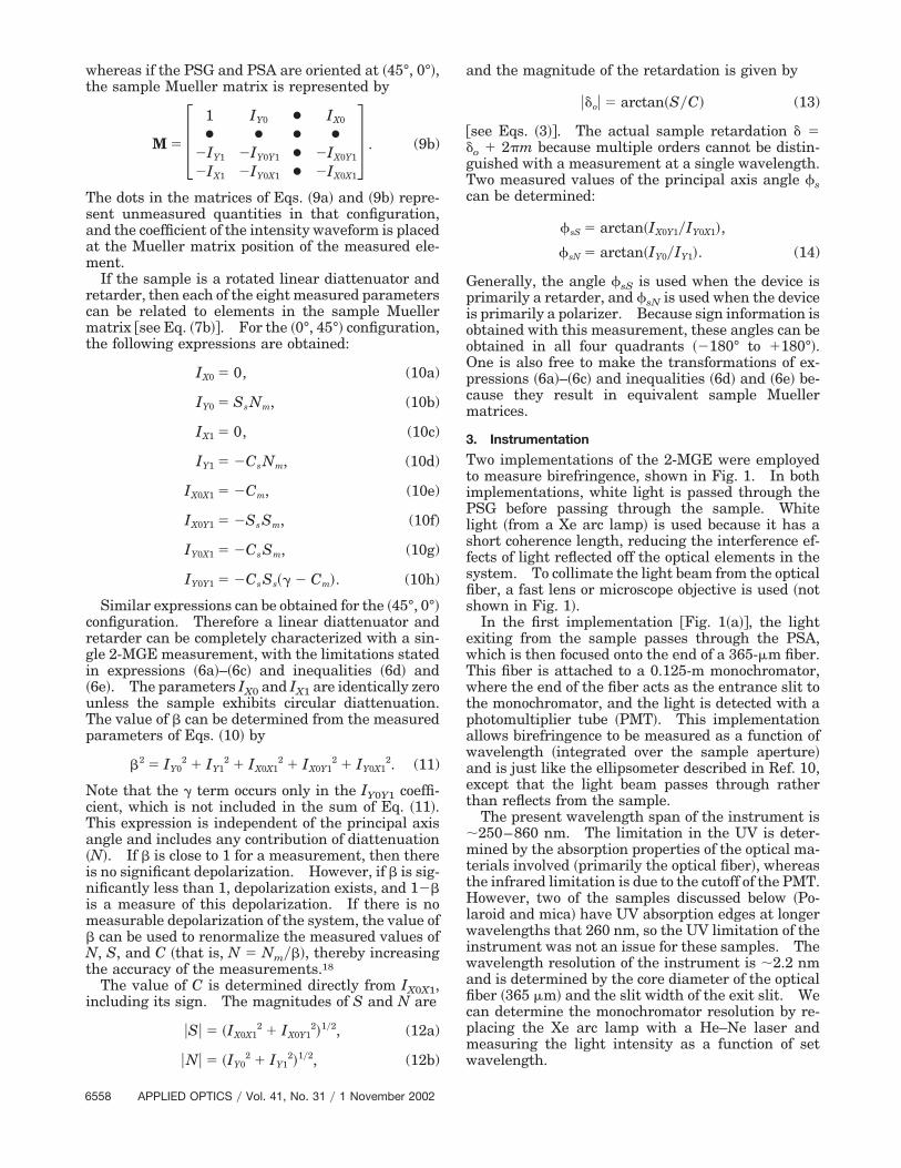
Two implementations of the 2-MGE were employedto measure birefringence, shown in Fig. 1. In bothimplementations, white light is passed through thePSG before passing through the sample. Whitelight �from a Xe arc lamp� is used because it has ashort coherence length, reducing the interference ef-fects of light reflected off the optical elements in thesystem. To collimate the light beam from the opticalfiber, a fast lens or microscope objective is used �notshown in Fig. 1�.
In the first implementation �Fig. 1�a��, the lightexiting from the sample passes through the PSA,which is then focused onto the end of a 365-�m fiber.This fiber is attached to a 0.125-m monochromator,where the end of the fiber acts as the entrance slit tothe monochromator, and the light is detected with aphotomultiplier tube �PMT�. This implementationallows birefringence to be measured as a function ofwavelength �integrated over the sample aperture�and is just like the ellipsometer described in Ref. 10,except that the light beam passes through ratherthan reflects from the sample.
The present wavelength span of the instrument is�250–860 nm. The limitation in the UV is deter-mined by the absorption properties of the optical ma-terials involved �primarily the optical fiber�, whereasthe infrared limitation is due to the cutoff of the PMT.However, two of the samples discussed below �Po-laroid and mica� have UV absorption edges at longerwavelengths that 260 nm, so the UV limitation of theinstrument was not an issue for these samples. Thewavelength resolution of the instrument is �2.2 nmand is determined by the core diameter of the opticalfiber �365 �m� and the slit width of the exit slit. Wecan determine the monochromator resolution by re-placing the Xe arc lamp with a He–Ne laser andmeasuring the light intensity as a function of setwavelength.
6558 APPLIED OPTICS � Vol. 41, No. 31 � 1 November 2002
In the second implementation �see Fig. 1�b��, themonochromator is replaced by an interference filter,so that only a small range of wavelengths are ob-served. Furthermore, the collection optics after thePSA are removed, and a 100-�m core fiber is used tocollect the light and pass it to the PMT. A lensmounted on an X–Y stage is then inserted betweenthe sample and the PSA, arranged such that the lightpassing through the sample is imaged onto the end ofthe optical fiber. In this case, moving the position ofthe lens will image a different part of the sample ontothe end of the fiber; and when we sweep the lens, aretardation, diattenuation, and fast-axis picture ofthe sample can then be taken. By properly position-ing the lens, the end of the optical fiber, and thesample, we can obtain different magnifications.Typically, we use a 7.5-cm focal-length lens, posi-tioned 12 cm from the sample and 20 cm from the endof the optical fiber. The resulting magnification is1.67. Of course, the insertion of the lens will perturbthe measurements. However, scanning X–Y back-ground measurements showed that the residual re-tardation from the lens is considerably less than theretardation of any sample here, so it can safely beignored.
In both implementations, the PMT is controlled bya biasing circuit, described in Ref. 11. This circuitdynamically changes the PMT biasing voltage toyield a constant dc from the PMT. If the light beamis blocked, then the PMT bias voltage will go to themaximum voltage, so that the PMT will not be dam-aged. Both set points �maximum voltage and max-
imum dc� can be set either from a front-panel knob orby a control voltage. As a result, if the intensity ishigh, the bias voltage will be low, and if the intensityis low, then the bias voltage will be high; in bothcases, the dc will be constant, as long as the PMTcircuit is in the current-control mode. This circuithas the distinct advantage in that large variations inlight intensity will not result in changes of the dcphotocurrent, making it more convenient to digitizethe incident waveform; the only result is that thesignal-to-noise ratio will be a function of the lightintensity.
The samples are attached to an aperture 2.5 mm indiameter. This aperture is then mounted in a holderthat allows for 360° rotation about the axis of thelight passing through the sample. Therefore thespectroscopic measurements integrate over the entire2.5-mm spot, whereas the X–Y scanning measure-ments measure the same parameters at different po-sitions within the 2.5-mm spot, but at a singlewavelength. The spatial resolution used for thescanning measurements is �40 �m.
4. Results and Discussion
To examine the 2-MGE as a birefringence measure-ment apparatus, we chose four standard optical ma-terials: a mica plate acting as a retarder, a Polaroidpolarizer, and two quartz multiorder quarter-waveplates �designed for quarter-wave operation at 633and 532 nm, respectively�. All these devices arestandard elements found in many optics laboratoriesand are nearly ideal in their primary range of oper-
Fig. 1. Two experimental configurations used in these experiments: �a� spectroscopic 2-MGE, �b� spatially resolved 2-MGE.
1 November 2002 � Vol. 41, No. 31 � APPLIED OPTICS 6559
ation. However, their behavior can be quite non-ideal outside this primary operation range. Polaroidpolarizers27 are complicated materials consisting of apolyvinyl alcohol matrix and a dichromophore polar-izing material, which will polarize only over a rangeof wavelengths. Mica retarders are known to ex-hibit some diattenuation, in part because of the dif-ferent reflectivities for light polarized parallel andperpendicular to the optic axis of the material. Mul-tiorder quarter-wave plates consist of single plates ofa birefringent material �such as crystalline quartz�.Because the plate of birefringent material is rela-tively thick ��1 mm�, it is really useful only at thedesign wavelength as the retardation deviates signif-icantly for other wavelengths.
A. Spectroscopic Birefringence
The spectroscopic birefringence was measured foreach sample at several azimuthal angles of the prin-cipal axis of the sample with respect to the measure-ment system. The incident light beam passedthrough a 2.5-mm aperture, thereby effectively inte-grating over the entire aperture. The results pre-sented in Subsections 4.A.1–4.A.3 represent one suchdata set, but the other data sets at different azi-muthal angles of the sample gave the same results�within experimental error�, apart from the obviousdifferences in the principal axis direction.
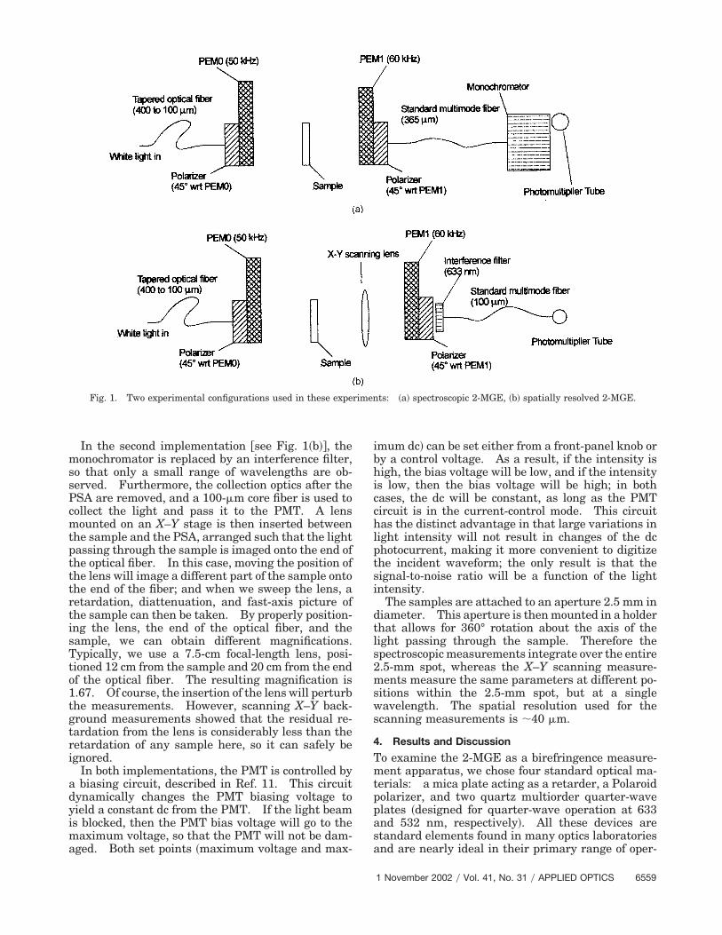
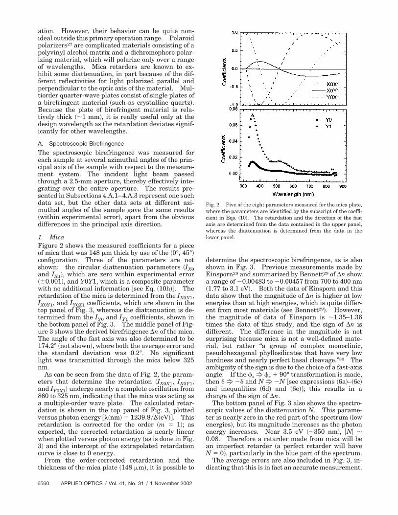
1. MicaFigure 2 shows the measured coefficients for a pieceof mica that was 148 �m thick by use of the �0°, 45°�configuration. Three of the parameters are notshown: the circular diattenuation parameters �IX0and IX1�, which are zero within experimental error��0.001�, and Y0Y1, which is a composite parameterwith no additional information �see Eq. �10h��. Theretardation of the mica is determined from the IX0X1,IX0Y1, and IY0X1 coefficients, which are shown in thetop panel of Fig. 3, whereas the diattenuation is de-termined from the IY0 and IY1 coefficients, shown inthe bottom panel of Fig. 3. The middle panel of Fig-ure 3 shows the derived birefringence �n of the mica.The angle of the fast axis was also determined to be174.2° �not shown�, where both the average error andthe standard deviation was 0.2°. No significantlight was transmitted through the mica below 325nm.
As can be seen from the data of Fig. 2, the param-eters that determine the retardation �IX0X1, IX0Y1,and IY0X1� undergo nearly a complete oscillation from860 to 325 nm, indicating that the mica was acting asa multiple-order wave plate. The calculated retar-dation is shown in the top panel of Fig. 3, plottedversus photon energy ��nm� � 1239.8�E�eV��. Thisretardation is corrected for the order �m � 1�; asexpected, the corrected retardation is nearly linearwhen plotted versus photon energy �as is done in Fig.3� and the intercept of the extrapolated retardationcurve is close to 0 energy.
From the order-corrected retardation and thethickness of the mica plate �148 �m�, it is possible to
determine the spectroscopic birefringence, as is alsoshown in Fig. 3. Previous measurements made byEinsporn28 and summarized by Bennett29 of �n showa range of �0.00483 to �0.00457 from 700 to 400 nm�1.77 to 3.1 eV�. Both the data of Einsporn and thisdata show that the magnitude of �n is higher at lowenergies than at high energies, which is quite differ-ent from most materials �see Bennett29�. However,the magnitude of data of Einsporn is �1.35–1.36times the data of this study, and the sign of �n isdifferent. The difference in the magnitude is notsurprising because mica is not a well-defined mate-rial, but rather “a group of complex monoclinic,pseudohexagonal phyllosilicates that have very lowhardness and nearly perfect basal cleavage.”30 Theambiguity of the sign is due to the choice of a fast-axisangle: If the sf s � 90° transformation is made,then �f �� and Nf �N �see expressions �6a�–�6c�and inequalities �6d� and �6e��; this results in achange of the sign of �n.
The bottom panel of Fig. 3 also shows the spectro-scopic values of the diattenuation N. This parame-ter is nearly zero in the red part of the spectrum �lowenergies�, but its magnitude increases as the photonenergy increases. Near 3.5 eV ��350 nm�, �N� �0.08. Therefore a retarder made from mica will bean imperfect retarder �a perfect retarder will haveN � 0�, particularly in the blue part of the spectrum.
The average errors are also included in Fig. 3, in-dicating that this is in fact an accurate measurement.
Fig. 2. Five of the eight parameters measured for the mica plate,where the parameters are identified by the subscript of the coeffi-cient in Eqs. �10�. The retardation and the direction of the fastaxis are determined from the data contained in the upper panel,whereas the diattenuation is determined from the data in thelower panel.
6560 APPLIED OPTICS � Vol. 41, No. 31 � 1 November 2002
These average errors are determined when we aver-age the individual stochastic errors of the determinedparameters at each wavelength. Although the aver-age error in the retardation is 0.005 rad, the mea-surement error is only �0.001 when either S or C isclose to zero. Therefore the instrument is muchmore accurate for small retardations than for largerretardations.
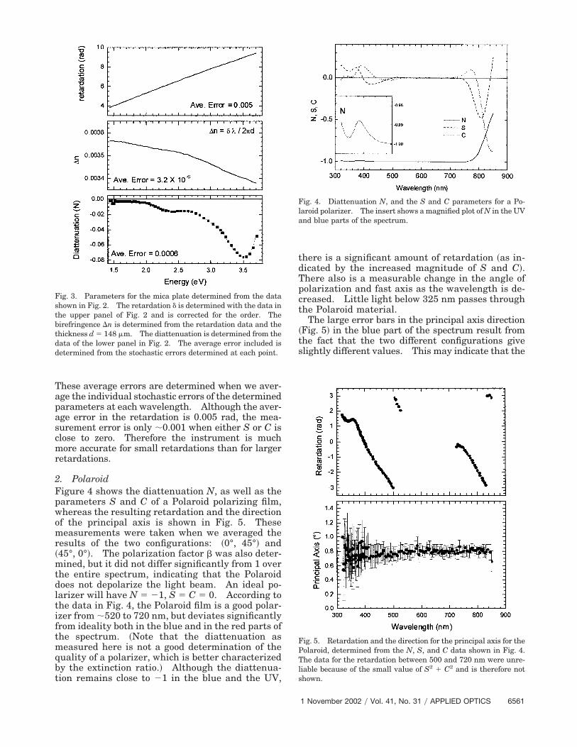
2. PolaroidFigure 4 shows the diattenuation N, as well as theparameters S and C of a Polaroid polarizing film,whereas the resulting retardation and the directionof the principal axis is shown in Fig. 5. Thesemeasurements were taken when we averaged theresults of the two configurations: �0°, 45°� and�45°, 0°�. The polarization factor � was also deter-mined, but it did not differ significantly from 1 overthe entire spectrum, indicating that the Polaroiddoes not depolarize the light beam. An ideal po-larizer will have N � �1, S � C � 0. According tothe data in Fig. 4, the Polaroid film is a good polar-izer from �520 to 720 nm, but deviates significantlyfrom ideality both in the blue and in the red parts ofthe spectrum. �Note that the diattenuation asmeasured here is not a good determination of thequality of a polarizer, which is better characterizedby the extinction ratio.� Although the diattenua-tion remains close to �1 in the blue and the UV,
there is a significant amount of retardation �as in-dicated by the increased magnitude of S and C�.There also is a measurable change in the angle ofpolarization and fast axis as the wavelength is de-creased. Little light below 325 nm passes throughthe Polaroid material.
The large error bars in the principal axis direction�Fig. 5� in the blue part of the spectrum result fromthe fact that the two different configurations giveslightly different values. This may indicate that the
Fig. 3. Parameters for the mica plate determined from the datashown in Fig. 2. The retardation � is determined with the data inthe upper panel of Fig. 2 and is corrected for the order. Thebirefringence �n is determined from the retardation data and thethickness d � 148 �m. The diattenuation is determined from thedata of the lower panel in Fig. 2. The average error included isdetermined from the stochastic errors determined at each point.
Fig. 4. Diattenuation N, and the S and C parameters for a Po-laroid polarizer. The insert shows a magnified plot of N in the UVand blue parts of the spectrum.
Fig. 5. Retardation and the direction for the principal axis for thePolaroid, determined from the N, S, and C data shown in Fig. 4.The data for the retardation between 500 and 720 nm were unre-liable because of the small value of S2 � C2 and is therefore notshown.
1 November 2002 � Vol. 41, No. 31 � APPLIED OPTICS 6561
Polaroid is no longer a simple linear retarder anddiattenuator in this region of the spectrum.
The effects in the red part of the spectrum are evenmore dramatic: The diattenuation rapidly drops offfrom �1, whereas S and C become more important.Although the Polaroid is a good polarizer at 720 nm,at 850 nm the Polaroid is more of a retarder than apolarizer. This is quite reasonable because the ma-trix material of a Polaroid �polyvinyl alcohol� is oftenused as a retarder.29 The amount of retardation�shown in Fig. 5� will depend on the thickness of thePolaroid, as well as other intrinsic properties of thematerial. No retardation data are shown between�500 and 720 nm because both S and C are small,making the retardation measurements inaccurate.
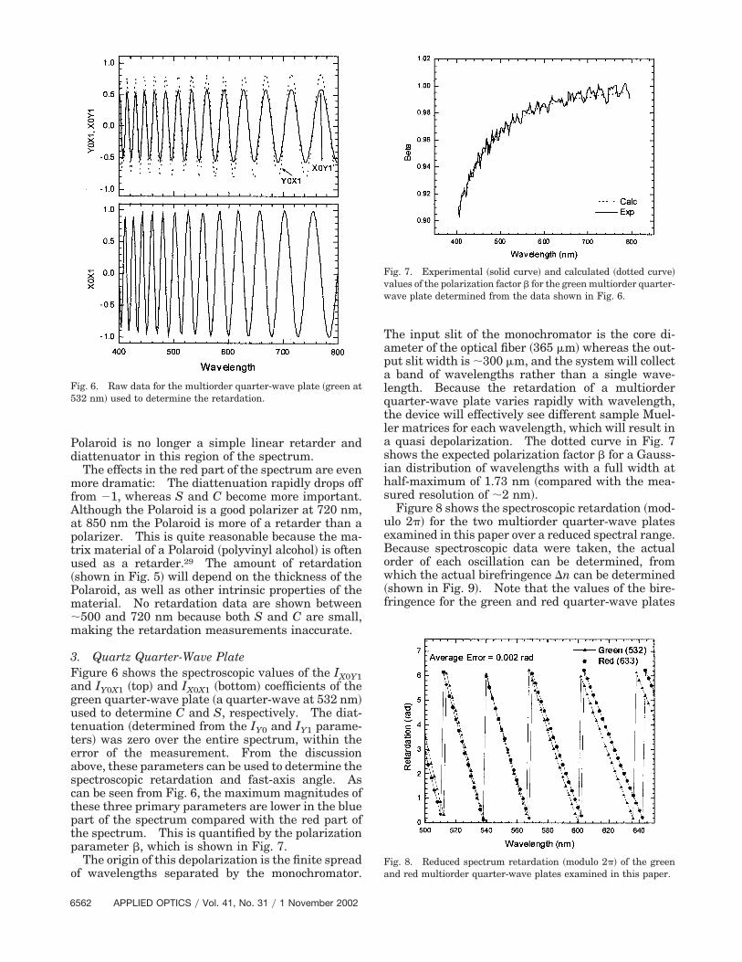
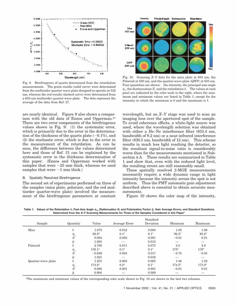
3. Quartz Quarter-Wave PlateFigure 6 shows the spectroscopic values of the IX0Y1and IY0X1 �top� and IX0X1 �bottom� coefficients of thegreen quarter-wave plate �a quarter-wave at 532 nm�used to determine C and S, respectively. The diat-tenuation �determined from the IY0 and IY1 parame-ters� was zero over the entire spectrum, within theerror of the measurement. From the discussionabove, these parameters can be used to determine thespectroscopic retardation and fast-axis angle. Ascan be seen from Fig. 6, the maximum magnitudes ofthese three primary parameters are lower in the bluepart of the spectrum compared with the red part ofthe spectrum. This is quantified by the polarizationparameter �, which is shown in Fig. 7.
The origin of this depolarization is the finite spreadof wavelengths separated by the monochromator.
The input slit of the monochromator is the core di-ameter of the optical fiber �365 �m� whereas the out-put slit width is �300 �m, and the system will collecta band of wavelengths rather than a single wave-length. Because the retardation of a multiorderquarter-wave plate varies rapidly with wavelength,the device will effectively see different sample Muel-ler matrices for each wavelength, which will result ina quasi depolarization. The dotted curve in Fig. 7shows the expected polarization factor � for a Gauss-ian distribution of wavelengths with a full width athalf-maximum of 1.73 nm �compared with the mea-sured resolution of �2 nm�.
Figure 8 shows the spectroscopic retardation �mod-ulo 2� for the two multiorder quarter-wave platesexamined in this paper over a reduced spectral range.Because spectroscopic data were taken, the actualorder of each oscillation can be determined, fromwhich the actual birefringence �n can be determined�shown in Fig. 9�. Note that the values of the bire-fringence for the green and red quarter-wave plates
Fig. 6. Raw data for the multiorder quarter-wave plate �green at532 nm� used to determine the retardation.
Fig. 7. Experimental �solid curve� and calculated �dotted curve�values of the polarization factor � for the green multiorder quarter-wave plate determined from the data shown in Fig. 6.
Fig. 8. Reduced spectrum retardation �modulo 2� of the greenand red multiorder quarter-wave plates examined in this paper.
6562 APPLIED OPTICS � Vol. 41, No. 31 � 1 November 2002
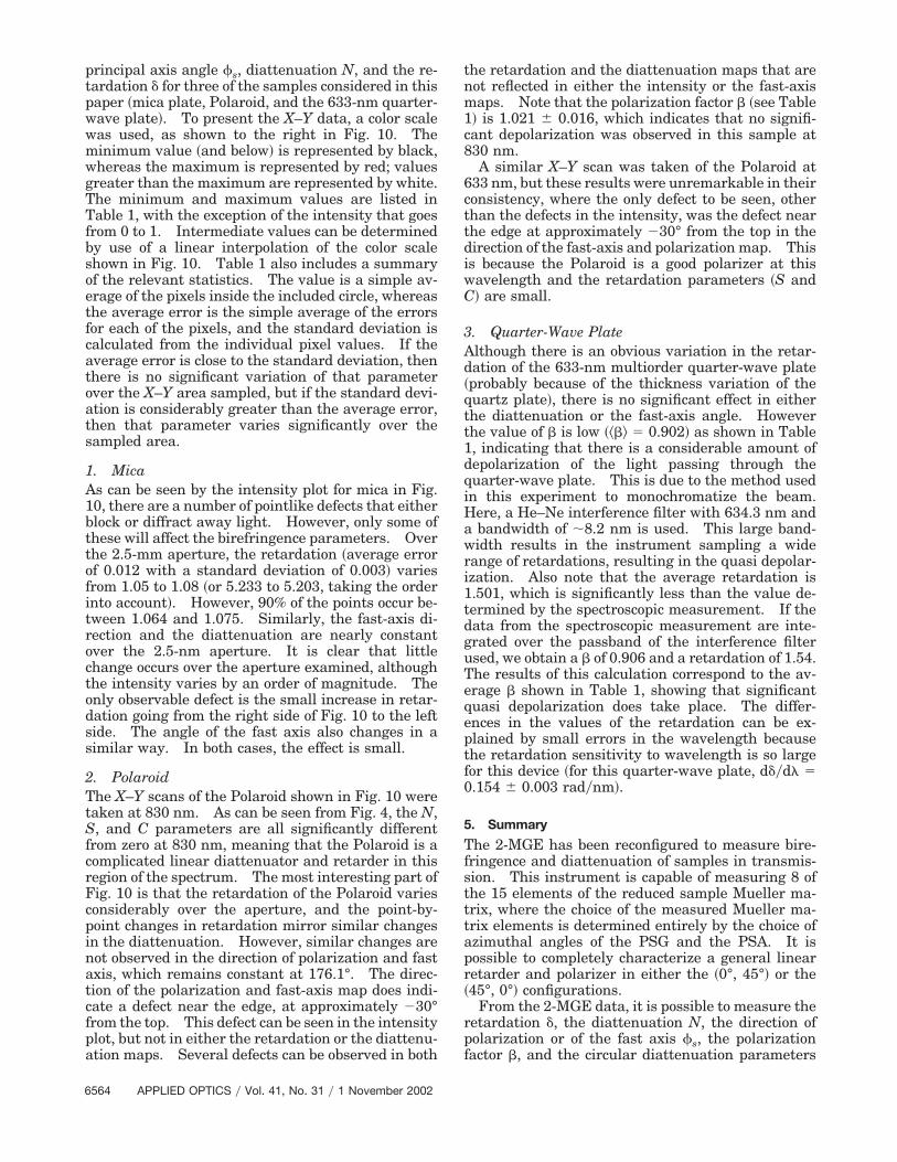
are nearly identical. Figure 9 also shows a compar-ison with the old data of Ennos and Opperman.31
There are two error components of the birefringencevalues shown in Fig. 9: �1� the systematic error,which is primarily due to the error in the determina-tion of the thickness of the quartz plate ��0.1%�, and�2� the stochastic error, which is due to the error inthe measurement of the retardation. As can beseen, the difference between the values determinedhere and those of Ref. 31 can be explained by thesystematic error in the thickness determination ofthis paper. �Ennos and Opperman worked withsamples that were �25 mm thick, whereas we usedsamples that were �1 mm thick.�
B. Spatially Resolved Birefringence
The second set of experiments performed on three ofthe samples �mica plate, polarizer, and the red mul-tiorder quarter-wave plate� involved the measure-ment of the birefringence parameters at constant
wavelength, but an X–Y stage was used to scan animaging lens over the apertured spot of the sample.To avoid coherence effects, a white-light source wasused, where the wavelength selection was obtainedwith either a He–Ne interference filter �633.4 nm,bandwidth of 8.2 nm� or a near-infrared interferencefilter �830.5 nm, bandwidth of 12 nm�. This schemeresults in much less light reaching the detector, sothe resultant signal-to-noise ratio is considerablyworse than for the measurements mentioned in Sub-section 4.A. These results are summarized in Table1 and show that, even with the reduced light level,the resulting errors are still reasonably small.
These spatially resolved 2-MGE measurementsnecessarily require a wide dynamic range in lightintensity because the intensity across the spot is notuniform. Thus the PMT automatic gain adjustmentdescribed above is essential to obtain accurate mea-surements.
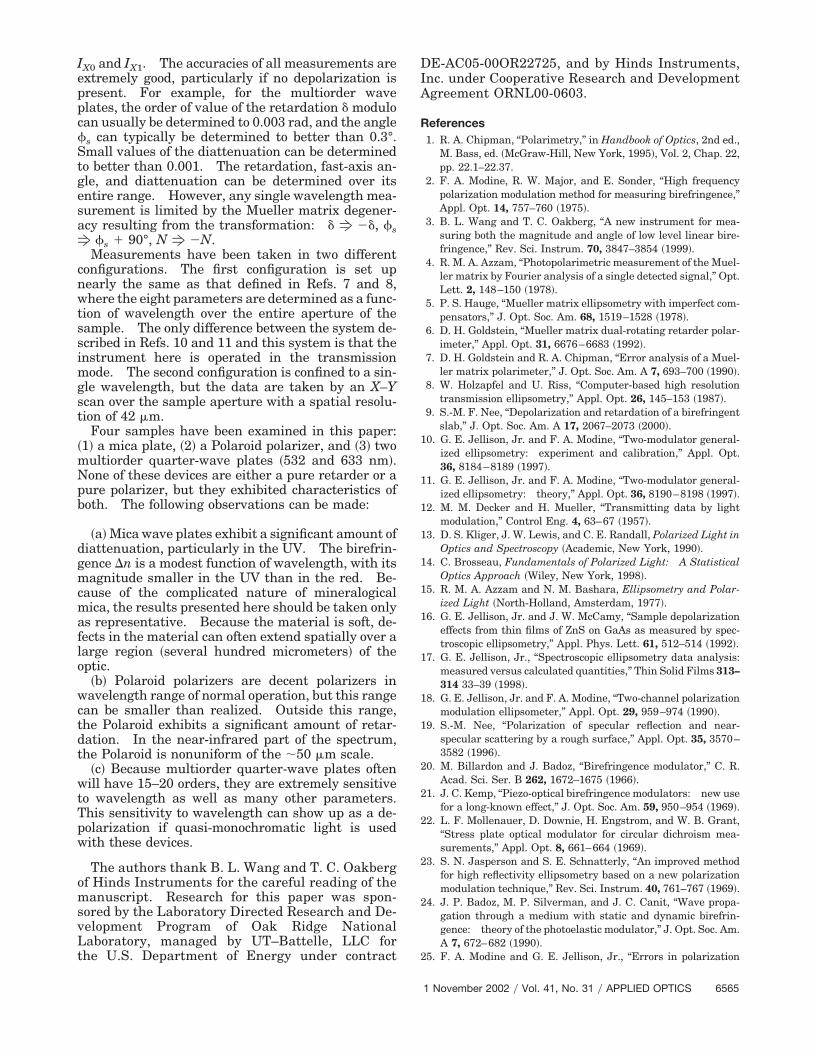
Figure 10 shows the color map of the intensity,
Fig. 9. Birefringence of quartz determined from the retardationmeasurements. The green results �solid curve� were determinedfrom the multiorder quarter-wave plate designed to operate at 532nm, whereas the red results �dashed curve� were determined froma 633-nm multiorder quarter-wave plate. The dots represent theaverage of the data from Ref. 27.
Fig. 10. Scanning X–Y data for the mica plate at 633 nm, thePolaroid at 830 nm, and the quarter-wave plate �QWP� at 633 nm.Four quantities are shown: the intensity, the principal axis angle s, the diattenuation N, and the retardation �. The values at eachpixel are indicated by the color scale to the right, where the max-imum and minimum values are listed in Table 1, except for theintensity in which the minimum is 0 and the maximum is 1.
Table 1. Values of the Retardation �, Fast-Axis Angle �s, Diattenuation N, and Polarization Factor �, their Average Errors, and Standard DeviationsDetermined from the X–Y Scanning Measurements for Three of the Samples Considered in this Papera
Sample Quantity Value Average ErrorStandardDeviation Minimum Maximum
Mica � 1.070 0.012 0.003 1.05 1.08 s 92.8° 0.1° 0.1° 92.2° 93.2°N 0.004 0.002 0.001 �0.01 0.01� 1.003 — 0.012 — —
Polaroid � 2.780 0.011 0.075 2.5 3.0 s 176.1° 0.1° 0.1° 175° 178°N �0.639 0.003 0.017 �0.75 �0.55� 1.021 — 0.016 — —
Quarter-wave plate � 1.501 0.003 0.005 1.48 1.52 s 174.8° 0.2° 0.1° 174.5° 175.0°N 0.000 0.001 0.001 �0.01 0.01� 0.904 — 0.009 — —
aThe maximum and minimum values of the corresponding color scale shown in Fig. 10 are shown in the last two columns.
1 November 2002 � Vol. 41, No. 31 � APPLIED OPTICS 6563
principal axis angle s, diattenuation N, and the re-tardation � for three of the samples considered in thispaper �mica plate, Polaroid, and the 633-nm quarter-wave plate�. To present the X–Y data, a color scalewas used, as shown to the right in Fig. 10. Theminimum value �and below� is represented by black,whereas the maximum is represented by red; valuesgreater than the maximum are represented by white.The minimum and maximum values are listed inTable 1, with the exception of the intensity that goesfrom 0 to 1. Intermediate values can be determinedby use of a linear interpolation of the color scaleshown in Fig. 10. Table 1 also includes a summaryof the relevant statistics. The value is a simple av-erage of the pixels inside the included circle, whereasthe average error is the simple average of the errorsfor each of the pixels, and the standard deviation iscalculated from the individual pixel values. If theaverage error is close to the standard deviation, thenthere is no significant variation of that parameterover the X–Y area sampled, but if the standard devi-ation is considerably greater than the average error,then that parameter varies significantly over thesampled area.
1. MicaAs can be seen by the intensity plot for mica in Fig.10, there are a number of pointlike defects that eitherblock or diffract away light. However, only some ofthese will affect the birefringence parameters. Overthe 2.5-mm aperture, the retardation �average errorof 0.012 with a standard deviation of 0.003� variesfrom 1.05 to 1.08 �or 5.233 to 5.203, taking the orderinto account�. However, 90% of the points occur be-tween 1.064 and 1.075. Similarly, the fast-axis di-rection and the diattenuation are nearly constantover the 2.5-nm aperture. It is clear that littlechange occurs over the aperture examined, althoughthe intensity varies by an order of magnitude. Theonly observable defect is the small increase in retar-dation going from the right side of Fig. 10 to the leftside. The angle of the fast axis also changes in asimilar way. In both cases, the effect is small.
2. PolaroidThe X–Y scans of the Polaroid shown in Fig. 10 weretaken at 830 nm. As can be seen from Fig. 4, the N,S, and C parameters are all significantly differentfrom zero at 830 nm, meaning that the Polaroid is acomplicated linear diattenuator and retarder in thisregion of the spectrum. The most interesting part ofFig. 10 is that the retardation of the Polaroid variesconsiderably over the aperture, and the point-by-point changes in retardation mirror similar changesin the diattenuation. However, similar changes arenot observed in the direction of polarization and fastaxis, which remains constant at 176.1°. The direc-tion of the polarization and fast-axis map does indi-cate a defect near the edge, at approximately �30°from the top. This defect can be seen in the intensityplot, but not in either the retardation or the diattenu-ation maps. Several defects can be observed in both
the retardation and the diattenuation maps that arenot reflected in either the intensity or the fast-axismaps. Note that the polarization factor � �see Table1� is 1.021 � 0.016, which indicates that no signifi-cant depolarization was observed in this sample at830 nm.
A similar X–Y scan was taken of the Polaroid at633 nm, but these results were unremarkable in theirconsistency, where the only defect to be seen, otherthan the defects in the intensity, was the defect nearthe edge at approximately �30° from the top in thedirection of the fast-axis and polarization map. Thisis because the Polaroid is a good polarizer at thiswavelength and the retardation parameters �S andC� are small.
3. Quarter-Wave PlateAlthough there is an obvious variation in the retar-dation of the 633-nm multiorder quarter-wave plate�probably because of the thickness variation of thequartz plate�, there is no significant effect in eitherthe diattenuation or the fast-axis angle. Howeverthe value of � is low ���� � 0.902� as shown in Table1, indicating that there is a considerable amount ofdepolarization of the light passing through thequarter-wave plate. This is due to the method usedin this experiment to monochromatize the beam.Here, a He–Ne interference filter with 634.3 nm anda bandwidth of �8.2 nm is used. This large band-width results in the instrument sampling a widerange of retardations, resulting in the quasi depolar-ization. Also note that the average retardation is1.501, which is significantly less than the value de-termined by the spectroscopic measurement. If thedata from the spectroscopic measurement are inte-grated over the passband of the interference filterused, we obtain a � of 0.906 and a retardation of 1.54.The results of this calculation correspond to the av-erage � shown in Table 1, showing that significantquasi depolarization does take place. The differ-ences in the values of the retardation can be ex-plained by small errors in the wavelength becausethe retardation sensitivity to wavelength is so largefor this device �for this quarter-wave plate, d��d �0.154 � 0.003 rad�nm�.
5. Summary
The 2-MGE has been reconfigured to measure bire-fringence and diattenuation of samples in transmis-sion. This instrument is capable of measuring 8 ofthe 15 elements of the reduced sample Mueller ma-trix, where the choice of the measured Mueller ma-trix elements is determined entirely by the choice ofazimuthal angles of the PSG and the PSA. It ispossible to completely characterize a general linearretarder and polarizer in either the �0°, 45°� or the�45°, 0°� configurations.
From the 2-MGE data, it is possible to measure theretardation �, the diattenuation N, the direction ofpolarization or of the fast axis s, the polarizationfactor �, and the circular diattenuation parameters
6564 APPLIED OPTICS � Vol. 41, No. 31 � 1 November 2002
IX0 and IX1. The accuracies of all measurements areextremely good, particularly if no depolarization ispresent. For example, for the multiorder waveplates, the order of value of the retardation � modulocan usually be determined to 0.003 rad, and the angle s can typically be determined to better than 0.3°.Small values of the diattenuation can be determinedto better than 0.001. The retardation, fast-axis an-gle, and diattenuation can be determined over itsentire range. However, any single wavelength mea-surement is limited by the Mueller matrix degener-acy resulting from the transformation: � f ��, sf s � 90°, N f �N.
Measurements have been taken in two differentconfigurations. The first configuration is set upnearly the same as that defined in Refs. 7 and 8,where the eight parameters are determined as a func-tion of wavelength over the entire aperture of thesample. The only difference between the system de-scribed in Refs. 10 and 11 and this system is that theinstrument here is operated in the transmissionmode. The second configuration is confined to a sin-gle wavelength, but the data are taken by an X–Yscan over the sample aperture with a spatial resolu-tion of 42 �m.
Four samples have been examined in this paper:�1� a mica plate, �2� a Polaroid polarizer, and �3� twomultiorder quarter-wave plates �532 and 633 nm�.None of these devices are either a pure retarder or apure polarizer, but they exhibited characteristics ofboth. The following observations can be made:
�a� Mica wave plates exhibit a significant amount ofdiattenuation, particularly in the UV. The birefrin-gence �n is a modest function of wavelength, with itsmagnitude smaller in the UV than in the red. Be-cause of the complicated nature of mineralogicalmica, the results presented here should be taken onlyas representative. Because the material is soft, de-fects in the material can often extend spatially over alarge region �several hundred micrometers� of theoptic.
�b� Polaroid polarizers are decent polarizers inwavelength range of normal operation, but this rangecan be smaller than realized. Outside this range,the Polaroid exhibits a significant amount of retar-dation. In the near-infrared part of the spectrum,the Polaroid is nonuniform of the �50 �m scale.
�c� Because multiorder quarter-wave plates oftenwill have 15–20 orders, they are extremely sensitiveto wavelength as well as many other parameters.This sensitivity to wavelength can show up as a de-polarization if quasi-monochromatic light is usedwith these devices.
The authors thank B. L. Wang and T. C. Oakbergof Hinds Instruments for the careful reading of themanuscript. Research for this paper was spon-sored by the Laboratory Directed Research and De-velopment Program of Oak Ridge NationalLaboratory, managed by UT–Battelle, LLC forthe U.S. Department of Energy under contract
DE-AC05-00OR22725, and by Hinds Instruments,Inc. under Cooperative Research and DevelopmentAgreement ORNL00-0603.
References1. R. A. Chipman, “Polarimetry,” in Handbook of Optics, 2nd ed.,
M. Bass, ed. �McGraw-Hill, New York, 1995�, Vol. 2, Chap. 22,pp. 22.1–22.37.
2. F. A. Modine, R. W. Major, and E. Sonder, “High frequencypolarization modulation method for measuring birefringence,”Appl. Opt. 14, 757–760 �1975�.
3. B. L. Wang and T. C. Oakberg, “A new instrument for mea-suring both the magnitude and angle of low level linear bire-fringence,” Rev. Sci. Instrum. 70, 3847–3854 �1999�.
4. R. M. A. Azzam, “Photopolarimetric measurement of the Muel-ler matrix by Fourier analysis of a single detected signal,” Opt.Lett. 2, 148–150 �1978�.
5. P. S. Hauge, “Mueller matrix ellipsometry with imperfect com-pensators,” J. Opt. Soc. Am. 68, 1519–1528 �1978�.
6. D. H. Goldstein, “Mueller matrix dual-rotating retarder polar-imeter,” Appl. Opt. 31, 6676–6683 �1992�.
7. D. H. Goldstein and R. A. Chipman, “Error analysis of a Muel-ler matrix polarimeter,” J. Opt. Soc. Am. A 7, 693–700 �1990�.
8. W. Holzapfel and U. Riss, “Computer-based high resolutiontransmission ellipsometry,” Appl. Opt. 26, 145–153 �1987�.
9. S.-M. F. Nee, “Depolarization and retardation of a birefringentslab,” J. Opt. Soc. Am. A 17, 2067–2073 �2000�.
10. G. E. Jellison, Jr. and F. A. Modine, “Two-modulator general-ized ellipsometry: experiment and calibration,” Appl. Opt.36, 8184–8189 �1997�.
11. G. E. Jellison, Jr. and F. A. Modine, “Two-modulator general-ized ellipsometry: theory,” Appl. Opt. 36, 8190–8198 �1997�.
12. M. M. Decker and H. Mueller, “Transmitting data by lightmodulation,” Control Eng. 4, 63–67 �1957�.
13. D. S. Kliger, J. W. Lewis, and C. E. Randall, Polarized Light inOptics and Spectroscopy �Academic, New York, 1990�.
14. C. Brosseau, Fundamentals of Polarized Light: A StatisticalOptics Approach �Wiley, New York, 1998�.
15. R. M. A. Azzam and N. M. Bashara, Ellipsometry and Polar-ized Light �North-Holland, Amsterdam, 1977�.
16. G. E. Jellison, Jr. and J. W. McCamy, “Sample depolarizationeffects from thin films of ZnS on GaAs as measured by spec-troscopic ellipsometry,” Appl. Phys. Lett. 61, 512–514 �1992�.
17. G. E. Jellison, Jr., “Spectroscopic ellipsometry data analysis:measured versus calculated quantities,” Thin Solid Films 313–314 33–39 �1998�.
18. G. E. Jellison, Jr. and F. A. Modine, “Two-channel polarizationmodulation ellipsometer,” Appl. Opt. 29, 959–974 �1990�.
19. S.-M. Nee, “Polarization of specular reflection and near-specular scattering by a rough surface,” Appl. Opt. 35, 3570–3582 �1996�.
20. M. Billardon and J. Badoz, “Birefringence modulator,” C. R.Acad. Sci. Ser. B 262, 1672–1675 �1966�.
21. J. C. Kemp, “Piezo-optical birefringence modulators: new usefor a long-known effect,” J. Opt. Soc. Am. 59, 950–954 �1969�.
22. L. F. Mollenauer, D. Downie, H. Engstrom, and W. B. Grant,“Stress plate optical modulator for circular dichroism mea-surements,” Appl. Opt. 8, 661–664 �1969�.
23. S. N. Jasperson and S. E. Schnatterly, “An improved methodfor high reflectivity ellipsometry based on a new polarizationmodulation technique,” Rev. Sci. Instrum. 40, 761–767 �1969�.
24. J. P. Badoz, M. P. Silverman, and J. C. Canit, “Wave propa-gation through a medium with static and dynamic birefrin-gence: theory of the photoelastic modulator,” J. Opt. Soc. Am.A 7, 672–682 �1990�.
25. F. A. Modine and G. E. Jellison, Jr., “Errors in polarization
1 November 2002 � Vol. 41, No. 31 � APPLIED OPTICS 6565
measurements due to static retardation in photoelastic mod-ulators,” Appl. Phys. Commun. 12, 121–139 �1993�.
26. G. E. Jellison, Jr. and F. A. Modine, “Accurate calibration of aphotoelastic modulator in a polarization modulation ellipsom-etry experiment,” in Polarization Considerations for OpticalSystems II, R. A. Chipman, ed., Proc. SPIE 1166, 231–241�1989�.
27. E. H. Land, “Some aspects of the development of sheet polar-izers,” J. Opt. Soc. Am. 41, 957–963 �1951�.
28. E. Einsporn, “Die Dispersion der Hauptbrechzahlen und desAschenwinkels des Glimmers,” Phys. Z. 37, 83–88 �1936�.
29. J. M. Bennett, “Polarizers,” in Handbook of Optics, 2nd ed., M.Bass, ed. �McGraw-Hill, New York, 1995�, Vol. 2, Chap. 3, pp.3.1–3.70.
30. C. Morris, ed., Dictionary of Science and Technology �Academ-ic, New York, 1992�, p. 1370.
31. A. E. Ennos and K. W. Opperman, “Birefringence of naturalquartz,” Appl. Opt. 5, 170 �1966�.
6566 APPLIED OPTICS � Vol. 41, No. 31 � 1 November 2002