Embed Size (px)
Citation preview
1
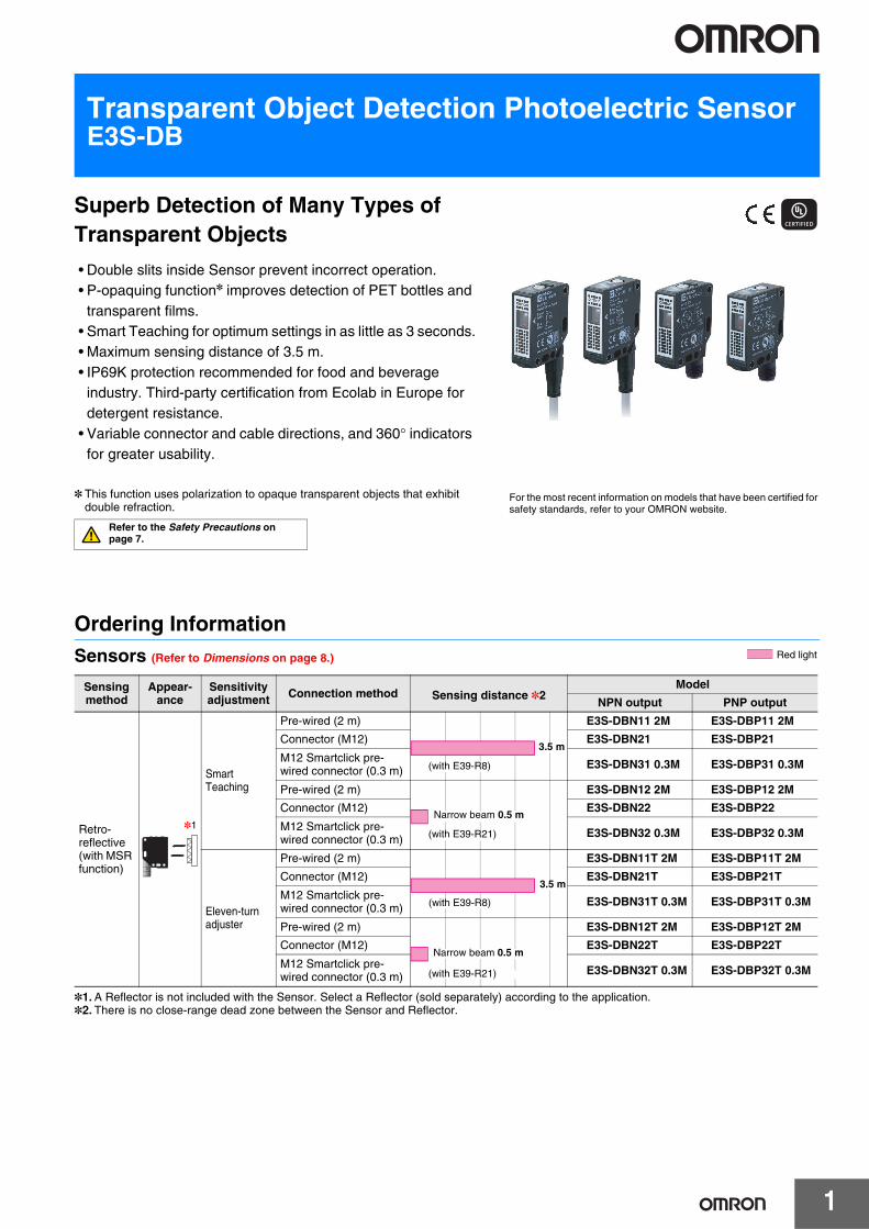
Transparent Object Detection Photoelectric SensorE3S-DB
Superb Detection of Many Types of Transparent Objects
• Double slits inside Sensor prevent incorrect operation.• P-opaquing function* improves detection of PET bottles and
transparent films.• Smart Teaching for optimum settings in as little as 3 seconds.• Maximum sensing distance of 3.5 m.• IP69K protection recommended for food and beverage
industry. Third-party certification from Ecolab in Europe fordetergent resistance.
• Variable connector and cable directions, and 360° indicatorsfor greater usability.
* This function uses polarization to opaque transparent objects that exhibitdouble refraction.
Ordering InformationSensors (Refer to Dimensions on page 8.)
*1.A Reflector is not included with the Sensor. Select a Reflector (sold separately) according to the application.*2. There is no close-range dead zone between the Sensor and Reflector.
Sensing method
Appear-ance
Sensitivity adjustment Connection method Sensing distance *2
Model
NPN output PNP output
Retro-reflective (with MSR function)
*1
Smart Teaching
Pre-wired (2 m) E3S-DBN11 2M E3S-DBP11 2M
Connector (M12) E3S-DBN21 E3S-DBP21
M12 Smartclick pre-wired connector (0.3 m) E3S-DBN31 0.3M E3S-DBP31 0.3M
Pre-wired (2 m) E3S-DBN12 2M E3S-DBP12 2M
Connector (M12) E3S-DBN22 E3S-DBP22
M12 Smartclick pre-wired connector (0.3 m) E3S-DBN32 0.3M E3S-DBP32 0.3M
Eleven-turn adjuster
Pre-wired (2 m) E3S-DBN11T 2M E3S-DBP11T 2M
Connector (M12) E3S-DBN21T E3S-DBP21T
M12 Smartclick pre-wired connector (0.3 m) E3S-DBN31T 0.3M E3S-DBP31T 0.3M
Pre-wired (2 m) E3S-DBN12T 2M E3S-DBP12T 2M
Connector (M12) E3S-DBN22T E3S-DBP22T
M12 Smartclick pre-wired connector (0.3 m) E3S-DBN32T 0.3M E3S-DBP32T 0.3M
For the most recent information on models that have been certified for safety standards, refer to your OMRON website.
Refer to the Safety Precautions on page 7.
Red light
(with E39-R8)
3.5 m
(with E39-R21)
Narrow beam 0.5 m
(with E39-R8)
3.5 m
(with E39-R21)
Narrow beam 0.5 m
E3S-DB
2
Accessories (Sold Separately)Sensor I/O Connectors (Connector on One End) (A Connector is required for a Sensor with a connector or pre-wired connector.)Connectors are not provided with the Sensors. Be sure to order a Connector separately.
*1 Refer to your OMRON website for details on the Y92E-S12PP and XS5.*2 The connectors will not rotate after they are connected.
Reflectors (A Reflector is required for each Retro-reflective Sensor.) (Refer to Dimensions on page 10.)Reflectors are not provided with the Sensors. Be sure to order a Reflector separately.
Note: 1. If you use the Reflector at any distance other than the rated distance, make sure that the stability indicator lights properly when you install the Sensor.
2. Refer to Engineering Data (Reference Value) on page 4 for details.* There is no close-range dead zone between the Sensor and Reflector.
Mounting Brackets (Refer to Dimensions on page 11.)A Mounting Bracket is not provided with the Sensor. It must be ordered separately as required.
Note: For details, refer to the Mounting Brackets on E39-L/E39-S/E39-R which can be accessed from your OMRON website.
Size Cable specifications Appearance Cable
length Model
*1M12 (4 pins)
Fire-retardant robot cable
*22 m Y92E-S12PP4S 2M
5 m Y92E-S12PP4S 5M
*22 m XS5F-D421-D80-F
5 m XS5F-D421-G80-F
Appearance Sensing distance* (reference value) Model Quantity Applicable Sensors Remarks
3.5 m E39-R1S
1
E3S-DB@@1(T) Standard model
2 m E39-R1K E3S-DB@@1(T) Non-fogging reflective plate
3 m E39-RP1 E3S-DB@@1(T) Special Polarizing Reflector
0.5 m (rated value) E39-R21 E3S-DB@@2(T) Narrow-beam Reflector
3.5 m (rated value) E39-R8 E3S-DB@@1(T) Standard model
1.5 m
E39-RS10
E3S-DB@@1(T)
Sheets
0.5 m E3S-DB@@2(T)
2.5 m
E39-RS11
E3S-DB@@1(T)
0.5 m E3S-DB@@2(T)
Type Appearance Model Quantity
Bottom-mounting E39-L192
1
Side-mounting E39-L193
Straight
Straight
E3S-DB
3
Ratings and Specifications
*1.Refer to Emission Spot Diameter vs. Distance in Engineering Data (Reference Value) on page 4 for details.*2. IP69K Degree of Protection Specification
IP69K is a protection standard against high temperature and high-pressure water defined in the Germanstandard DIN 40050, Part 9. The test piece is sprayed with water at 80°C at a water pressure of 80 to 100 BAR using a specified nozzle shape at a rate of 14 to 16 liters/min.The distance between the test piece and nozzle is 10 to 15 cm, and water is sprayed horizontally for 30 seconds each at 0°, 30°, 60°, and 90° while rotating the test piece on a horizontal plane.
Sensing method Retro-reflective (with MSR function)
Model NPN output E3S-DBN@1 E3S-DBN@1T E3S-DBN@2 E3S-DBN@2T
Item PNP output E3S-DBP@1 E3S-DBP@1T E3S-DBP@2 E3S-DBP@2T
Sensing distance 0 to 3.5 m (with E39-R8) 0 to 0.5 m (with E39-R21)
Spot diameter (reference value)*1 6-mm dia. (at sensing distance of 250 mm) 2.5-mm dia. (at sensing distance of 200 mm)
Light source (wavelength) Red LED (624 nm)
Power supply voltage 10 to 30 VDC, including 10% ripple (p-p)
Power consumption 720 mW max. (current consumption: 30 mA max. at power supply voltage of 24 VDC)
Control output Load power supply voltage: 30 VDC max., Load current: 100 mA max. (Residual voltage: 2 V max.)Open-collector output (NPN/PNP output depending on model.)
Indicators Light indicator (orange) and stability indicator (green)
Protection circuits Reversed power supply polarity protection, output short-circuit protection, reversed output polarity protection, and mutual interference prevention
Response time Operate or reset: 0.5 ms max.
Sensitivity adjustment Smart Teaching Eleven-turn adjuster Smart Teaching Eleven-turn adjuster
Smart Teaching lock function Provided. --- Provided. ---
Automatic compensation (AC3) Provided (OFF by default). --- Provided (OFF by
default). ---
Ambient illumination (Receiver side) Incandescent lamp: 3,000 lx max., Sunlight: 10,000 lx max.
Ambient temperature range Operating: −25 to 60°C, Storage: −40 to 70°C (with no icing or condensation)
Ambient humidity range Operating: 35% to 85%, Storage: 35% to 95% (with no condensation)
Insulation resistance 20 MΩ min. (at 500 VDC)
Dielectric strength 1,000 VAC at 50/60 Hz for 1 minute
Vibration resistance Destruction: 10 to 55 Hz with double amplitude of 1.5 mm for 2 hours each in X, Y, and Z directions
Shock resistance Destruction: 500 m/s2 3 times each in X, Y, and Z directions
Degree of protection*2 IEC IP67, DIN 40050-9 IP69K
Connection methodPre-wired cable (standard cable length: 2 m)Connector (M12, 4 pins)Pre-wired connector (standard cable length: 0.3 m/M12, 4 pins)
Weight (packed state/Sensor only)
Pre-wired models Approx. 80 g/approx. 60 g
Models with connector Approx. 60 g/approx. 40 g
Models with pre-wired connector Approx. 180 g/approx. 160 g
Materials
Case Polybutylene terephthalate (PBT)/ABS
Lens Methacrylic resin (PMMA)
Indicators Methacrylic resin (PMMA)
Sensitivity adjuster and operation selector
Polyester elastomer
Cable Polyvinyl chloride (PVC)
Accessories Instruction manual
E3S-DB
4
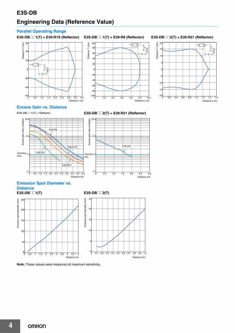
Engineering Data (Reference Value)
Note: These values were measured at maximum sensitivity.
Parallel Operating RangeE3S-DB@@1(T) + E39-R1S (Reflector) E3S-DB@@1(T) + E39-R8 (Reflector) E3S-DB@@2(T) + E39-R21 (Reflector)
Excess Gain vs. DistanceE3S-DB@@1(T) + Reflector E3S-DB@@2(T) + E39-R21 (Reflector)
Emission Spot Diameter vs. DistanceE3S-DB@@1(T) E3S-DB@@2(T)
60
−600.5 1.0 1.5 2.0 2.5 3.0 3.5 4.00
−40
−20
0
20
40
Y
X
Distance x (m)
Dis
tanc
e Y
(m
m)
Distance x (m)
Dis
tanc
e Y
(m
m)
−40
−20
0
20
40
80
60
−80
−60
100
−1001.0 2.0 3.0 4.0 5.0 6.00
Y
X
20
−200.2 0.4 0.6 0.8 1.0 1.2 1.4 1.60
Distance x (m)
−10
−5
0
5
10
15
−15
Y
X
Dis
tanc
e Y
(m
m)
100.0
0.10.5 1.0 1.5 2.0 2.5 3.0 4.0 5.03.5 4.50
1.0
10.0
Distance (m)
E39-R1S
E39-R21
E39-R8
Operating level
Exc
ess
gain
rat
io (
mul
tiple
)
E39-RP1
100.0
0.10.5 1.0 1.5 2.0 2.5 3.00
Distance (m)
1.0
10.0
E39-R21
Exc
ess
gain
rat
io (
mul
tiple
)
Operating level
250
00.5 1.51 2 2.5 3 3.5 4 4.5 50
50
0
100
150
200
Distance (m)
Em
issi
on s
pot d
iam
eter
(m
m)
Distance (m)
Em
issi
on s
pot d
iam
eter
(m
m) 25
0.1 0.30.2 0.4 0.5 0.6 0.7 0.8 0.9 1.00
5
0
10
15
20
E3S-DB
5
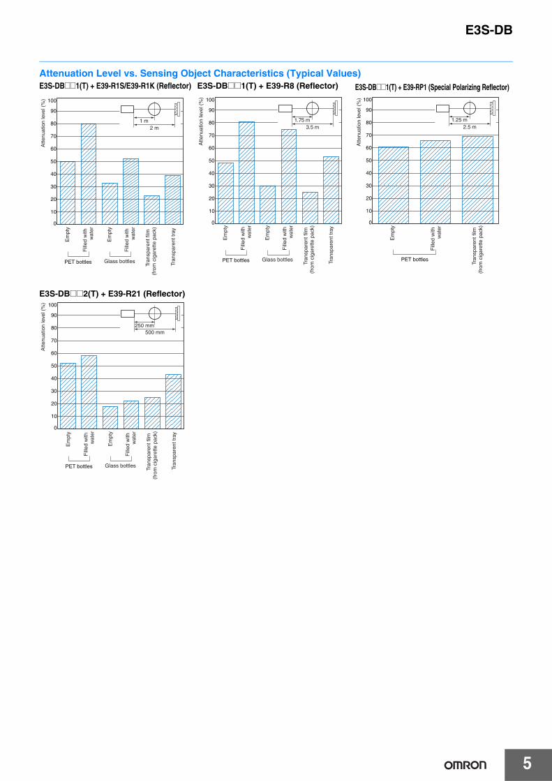
Attenuation Level vs. Sensing Object Characteristics (Typical Values)E3S-DB@@1(T) + E39-R1S/E39-R1K (Reflector) E3S-DB@@1(T) + E39-R8 (Reflector) E3S-DB@@1(T) + E39-RP1 (Special Polarizing Reflector)
E3S-DB@@2(T) + E39-R21 (Reflector)
100
0
30
50
70
10
40
60
80
90
20
2 m1 m
PET bottles Glass bottles
Atte
nuat
ion
leve
l (%
)
Em
pty
Fill
ed w
ith
wat
er
Em
pty
Fill
ed w
ith
wat
er
Tran
spar
ent f
ilm
(fro
m c
igar
ette
pac
k)
Tran
spar
ent t
ray
PET bottles Glass bottles
100
0
30
50
70
10
40
60
80
90
20
3.5 m1.75 m
Atte
nuat
ion
leve
l (%
)
Em
pty
Fill
ed w
ith
wat
er
Em
pty
Fill
ed w
ith
wat
er
Tran
spar
ent f
ilm
(fro
m c
igar
ette
pac
k)
Tran
spar
ent t
ray
100
0
30
50
70
10
40
60
80
90
20
2.5 m1.25 m
PET bottles
Atte
nuat
ion
leve
l (%
)
Em
pty
Fill
ed w
ith
wat
er
Tran
spar
ent f
ilm
(fro
m c
igar
ette
pac
k)
100
0
30
50
70
10
40
60
80
90
20
500 mm250 mm
PET bottles Glass bottles
Atte
nuat
ion
leve
l (%
)
Em
pty
Fill
ed w
ith
wat
er
Em
pty
Fill
ed w
ith
wat
er
Tran
spar
ent f
ilm
(fro
m c
igar
ette
pac
k)
Tran
spar
ent t
ray
E3S-DB
6
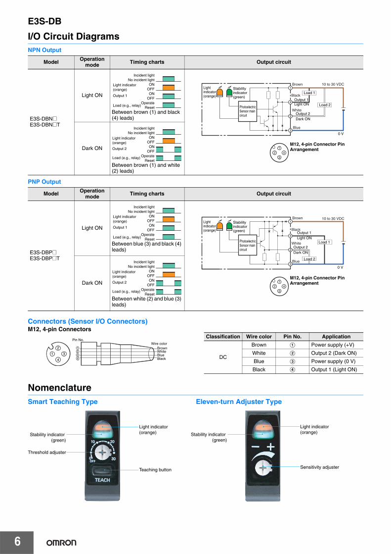
I/O Circuit DiagramsNPN Output
PNP Output
Connectors (Sensor I/O Connectors)M12, 4-pin Connectors
NomenclatureSmart Teaching Type Eleven-turn Adjuster Type
Model Operation mode Timing charts Output circuit
E3S-DBN@E3S-DBN@T
Light ON
Between brown (1) and black (4) leads)
Dark ON
Between brown (1) and white (2) leads)
Incident lightNo incident light
ONOFFON
OFFOperate
Reset
Light indicator (orange)
Output 1
Load (e.g., relay)4
2
3
1
Load 2Output 1 Light ON
Output 2 Dark ON
0 V
10 to 30 VDC
Load 1Stability indicator (green)
Light indicator (orange)
Photoelectric Sensor main circuit
Blue
Brown
Black
White
3
1
2 4
M12, 4-pin Connector Pin Arrangement
Incident lightNo incident light
ONOFFON
OFFOperate
Reset
Output 2
Load (e.g., relay)
Light indicator (orange)
Model Operation mode Timing charts Output circuit
E3S-DBP@E3S-DBP@T
Light ON
Between blue (3) and black (4) leads)
Dark ON
Between white (2) and blue (3) leads)
Incident lightNo incident light
ONOFFON
OFFOperate
Reset
Light indicator (orange)
Output 1
Load (e.g., relay)
Blue
Brown
Output 1Light ON
Output 2Dark ON
0 V
10 to 30 VDCStability indicator (green)
Light indicator (orange) Black
White
4
2
3
1
Load 2
Load 1Photoelectric Sensor main circuit
3
1
2 4
M12, 4-pin Connector Pin Arrangement
Incident lightNo incident light
ONOFFON
OFFOperate
Reset
Output 2
Load (e.g., relay)
Light indicator (orange)
2
4
1 3
1234
Brown
BlueWhite
Black
Pin No.Wire color
Classification Wire color Pin No. Application
DC
Brown A Power supply (+V)
White B Output 2 (Dark ON)
Blue C Power supply (0 V)
Black D Output 1 (Light ON)
Stability indicator (green)
Threshold adjuster
Light indicator (orange) Stability indicator
(green)
Light indicator (orange)
Teaching button Sensitivity adjuster
E3S-DB
7
Safety PrecautionsBe sure to read the precautions for all models in the website at: http://www.ia.omron.com/.
Do not use the product with voltage in excess of the rated voltage.Excess voltage may result in malfunction or fire.
Never use the product with an AC power supply.Otherwise, explosion may result.
The maximum power supply voltage is 30 VDC. Before turning the power ON, make sure that the power supply voltage does not exceed the maximum voltage.
Do not use the product under a chemical or an oil environment without prior evaluation.
Be sure to follow the safety precautions below for added safety.1. Do not use the product in an environment where explosive or
flammable gas is present.2. The degree of protection is IP69K, but do not use the product in
water, rain, or outdoors.3. Do not use the product in atmospheres or environments that
exceed product ratings.4. Do not use the product in locations subject to direct sunlight.5. Do not use the product in locations subject to direct vibration or
shock.6. Do not use thinner, alcohol, or other organic solvents. Otherwise,
the optical properties and degree of protection may be degraded.7. Do not attempt to disassemble, repair, or modify the product in
any way.8. When disposing of the product, treat it as industrial waste.9. Do not use highly concentrated cleaning agents. Otherwise,
malfunction may result. Also, do not use high-pressure water with a level of pressure that exceeds the stipulated level. Otherwise, the degree of protection may be reduced.
10. Perform sensitivity adjustment with the torque of 0.06 N·m or less.11. Do not pull on the cable with excessive strength.12. Do not exert excessive force on the connector section.13. This product cannot be used as a detection system to protect
human bodies.14. These Sensors are certificated for the UL standard on the
assumption of usage in a Class 2 circuit. Use them with Class 2 power supplies in the United States or Canada. Use the OMRON XS2F-D4-series or XS5F-D4-series Cables. Cables that have wires less than AWG24 (0.2 mm2) are for connection to terminal blocks and are not for field splicing. External overcurrent protection of 1 A for AWG26, 2 A for AWG24, or 3 A for AWG22 wire must be provided for cable protection.
1. If the Sensor wiring is placed in the same conduits or ducts as high-voltage or high-power lines, inductive noise may cause malfunction or damage. Wire the cables separately or use a shielded cable.
2. If a commercial switching regulator is used, ground the FG (frame ground) terminal.
3. The Sensor will be able to detect objects 100 ms after the power supply is tuned ON. Start using the Sensor 100 ms or more after turning ON the power supply. If the load and the Sensor are connected to separate power supplies, be sure to turn ON the Sensor first.
4. Output pulses may occur when the power supply is turned OFF.We recommend that you turn OFF the power supply to the load or load line first.
5. Use M4 screws to mount the sensor and tighten each screw to a maximum torque of 1.2 N·m.
WARNING
Precautions for Safe Use
Precautions for Correct Use
E3S-DB
8
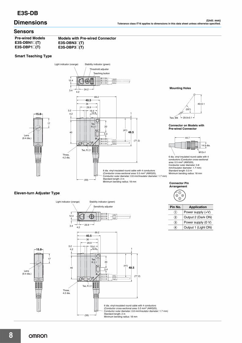
DimensionsSensors
(Unit: mm)Tolerance class IT16 applies to dimensions in this data sheet unless otherwise specified.
6 dia. vinyl-insulated round cable with 4 conductors (Conductor cross-sectional area: 0.5 mm2 (AWG20), Conductor outer diameter: 0.8 mm/Insulator diameter: 1.7 mm)Standard length: 2 mMinimum bending radius: 18 mm
Lens (9.4 dia.)
Three, 4.2 dia.
Stability indicator (green)Light indicator (orange)
Sensitivity adjuster
17
40.569.2
(33)
48.5
(77.2)
(41)
20
5.4
29.9
12.919.43.2
36
40
4.2
Two, R: 2.1
1
12.4
3.44.2
23.9
15.8
Two, R: 2.1
Stability indicator (green)Light indicator (orange)
Threshold adjuster
Teaching button
6 dia. vinyl-insulated round cable with 4 conductors (Conductor cross-sectional area: 0.5 mm2 (AWG20), Conductor outer diameter: 0.8 mm/Insulator diameter: 1.7 mm)Standard length: 2 mMinimum bending radius: 18 mm
Lens (9.4 dia.)
Three, 4.2 dia.
17
40.569.2
(33)
48.5
(77.2)
(41)
20
5.4
29.9
12.919.43.2
36
40
4.2
Two, R: 2.1
1
12.4
3.44.2
24.2
15.8
Two, R: 2.1
Pre-wired ModelsE3S-DBN1@(T)E3S-DBP1@(T)
Smart Teaching Type
Eleven-turn Adjuster Type
Models with Pre-wired ConnectorE3S-DBN3@(T)E3S-DBP3@(T)
Connector on Models with Pre-wired Connector
44.7
14.9 dia.
M12×1
6 dia. vinyl-insulated round cable with 4 conductors (Conductor cross-sectional area: 0.5 mm2 (AWG20), Conductor outer diameter: 0.8 mm/Insulator diameter: 1.7 mm)Standard length: 0.3 mMinimum bending radius: 18 mm
Pin No. Application
A Power supply (+V)
B Output 2 (Dark ON)
C Power supply (0 V)
D Output 1 (Light ON)
3
1
2 4
Connector Pin Arrangement
40±0.1
29.9±0.1Two, M4
(53°)
Mounting Holes
E3S-DB
9
Stability indicator (green)Light indicator (orange)
Threshold adjuster
Teaching button
Lens (9.4 dia.)
Three, 4.2 dia.
Two, R: 2.1
Connector M12
17
40.555.5
(33)
48.5
(63.5)
41
20
5.4
29.9
12.919.43.2
36
40
12.4
3.44.2
24.2
4.2
Two, R: 2.1
115.840±0.1
29.9±0.1Two, M4
(53°)
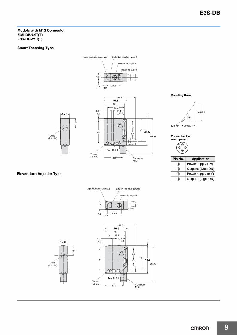
Models with M12 ConnectorE3S-DBN2@(T)E3S-DBP2@(T)
Smart Teaching Type
ConnectorM12
Stability indicator (green)Light indicator (orange)
Sensitivity adjuster
Lens (9.4 dia.)
Three, 4.2 dia.
Two, R: 2.1
40.555.5
(33)
48.5
(63.5)
41
20
5.4
29.9
12.919.43.2
36
15.8
17
40
4.2 1
12.4
3.4 4.223.9
Two, R: 2.1
Eleven-turn Adjuster Type
Pin No. Application
A Power supply (+V)
B Output 2 (Dark ON)
C Power supply (0 V)
D Output 1 (Light ON)
3
1
2 4
Connector Pin Arrangement
Mounting Holes
E3S-DB
10
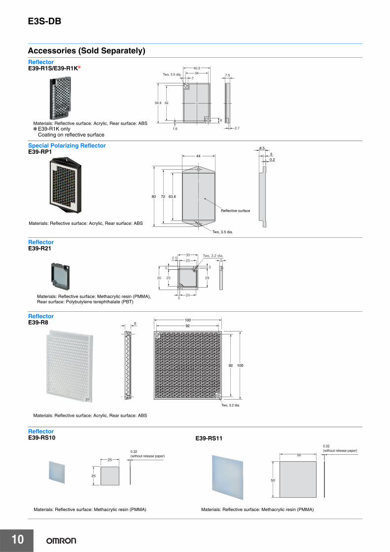
Accessories (Sold Separately)ReflectorE39-R1S/E39-R1K*
34
40.3
52 59.9
2.7
8
1.6
7.5 7
Two, 3.5 dia.
Materials: Reflective surface: Acrylic, Rear surface: ABS* E39-R1K only
Coating on reflective surface
72 63.680
44
Two, 3.5 dia.
Reflective surface
3
8.5
0.2
Materials: Reflective surface: Acrylic, Rear surface: ABS
Special Polarizing ReflectorE39-RP1
324
2535
5
2.530
25
3
29
Two, 3.2 dia.5
ReflectorE39-R21
Materials: Reflective surface: Methacrylic resin (PMMA), Rear surface: Polybutylene terephthalate (PBT)
9100
100
92
92
10000
10000
92
92
Two, 3.2 dia.
Materials: Reflective surface: Acrylic, Rear surface: ABS
ReflectorE39-R8
25
25
0.32 (without release paper)
50
50
0.32 (without release paper)
ReflectorE39-RS10
Materials: Reflective surface: Methacrylic resin (PMMA)
E39-RS11
Materials: Reflective surface: Methacrylic resin (PMMA)
E3S-DB
11
R2.25
Two, R5
54.5
29.9
4.5
10.1
R2.25
42.9
R49.9±0.1
58.861.8
31.8
(3)
15
40±0.1
Two, 4.5-dia. holes
5
2025.4
R5
4.5
23.8
8.8
(3)
R1
4.5 dia.R2.25
18.3
30°28.8
R25±0.1
R2.25
R3.5
5°
90°±0.5°
R3 max.
R49.9
5°
30°
R25
A*
47.6
t=3
40
29.9
54.5
42.9
26.2
4.5 dia.
47.6
33.3
54.5
90°
61.8
44
Mounting BracketsE39-L192
Material: SUS304
With Sensor Mounted
* The Mounting Bracket can be attached to side A.
6.57
10
6.5
10
7
(3)
25
11.4 11.4
3520±0.120±0.1
4.5 dia.
3.9 3.9Six, R2.25 Six, R2.25
R20±0.1 R20±0.1
4.5 dia.
90°±0.5°
(3)
R1 25
20 20 7.148.5
5140.8
22.9
B*
77
15
20°
R20
20°
R20
90°
20° 20°
E39-L193
Material: SUS304
With Sensor Mounted
* The Mounting Bracket can be attached to side B.

MEMO
12
Terms and Conditions of Sale1. Offer; Acceptance. These terms and conditions (these "Terms") are deemed
part of all quotes, agreements, purchase orders, acknowledgments, price lists,catalogs, manuals, brochures and other documents, whether electronic or inwriting, relating to the sale of products or services (collectively, the "Products")by Omron Electronics LLC and its subsidiary companies (“Omron”). Omronobjects to any terms or conditions proposed in Buyer’s purchase order or otherdocuments which are inconsistent with, or in addition to, these Terms.
2. Prices; Payment Terms. All prices stated are current, subject to change with-out notice by Omron. Omron reserves the right to increase or decrease priceson any unshipped portions of outstanding orders. Payments for Products aredue net 30 days unless otherwise stated in the invoice.
3. Discounts. Cash discounts, if any, will apply only on the net amount of invoicessent to Buyer after deducting transportation charges, taxes and duties, and willbe allowed only if (i) the invoice is paid according to Omron’s payment termsand (ii) Buyer has no past due amounts.
4. Interest. Omron, at its option, may charge Buyer 1-1/2% interest per month orthe maximum legal rate, whichever is less, on any balance not paid within thestated terms.
5. Orders. Omron will accept no order less than $200 net billing. 6. Governmental Approvals. Buyer shall be responsible for, and shall bear all
costs involved in, obtaining any government approvals required for the impor-tation or sale of the Products.
7. Taxes. All taxes, duties and other governmental charges (other than generalreal property and income taxes), including any interest or penalties thereon,imposed directly or indirectly on Omron or required to be collected directly orindirectly by Omron for the manufacture, production, sale, delivery, importa-tion, consumption or use of the Products sold hereunder (including customsduties and sales, excise, use, turnover and license taxes) shall be charged toand remitted by Buyer to Omron.
8. Financial. If the financial position of Buyer at any time becomes unsatisfactoryto Omron, Omron reserves the right to stop shipments or require satisfactorysecurity or payment in advance. If Buyer fails to make payment or otherwisecomply with these Terms or any related agreement, Omron may (without liabil-ity and in addition to other remedies) cancel any unshipped portion of Prod-ucts sold hereunder and stop any Products in transit until Buyer pays allamounts, including amounts payable hereunder, whether or not then due,which are owing to it by Buyer. Buyer shall in any event remain liable for allunpaid accounts.
9. Cancellation; Etc. Orders are not subject to rescheduling or cancellationunless Buyer indemnifies Omron against all related costs or expenses.
10. Force Majeure. Omron shall not be liable for any delay or failure in deliveryresulting from causes beyond its control, including earthquakes, fires, floods,strikes or other labor disputes, shortage of labor or materials, accidents tomachinery, acts of sabotage, riots, delay in or lack of transportation or therequirements of any government authority.
11. Shipping; Delivery. Unless otherwise expressly agreed in writing by Omron:a. Shipments shall be by a carrier selected by Omron; Omron will not drop ship
except in “break down” situations.b. Such carrier shall act as the agent of Buyer and delivery to such carrier shall
constitute delivery to Buyer;c. All sales and shipments of Products shall be FOB shipping point (unless oth-
erwise stated in writing by Omron), at which point title and risk of loss shallpass from Omron to Buyer; provided that Omron shall retain a security inter-est in the Products until the full purchase price is paid;
d. Delivery and shipping dates are estimates only; ande. Omron will package Products as it deems proper for protection against nor-
mal handling and extra charges apply to special conditions.12. Claims. Any claim by Buyer against Omron for shortage or damage to the
Products occurring before delivery to the carrier must be presented in writingto Omron within 30 days of receipt of shipment and include the original trans-portation bill signed by the carrier noting that the carrier received the Productsfrom Omron in the condition claimed.
13. Warranties. (a) Exclusive Warranty. Omron’s exclusive warranty is that theProducts will be free from defects in materials and workmanship for a period oftwelve months from the date of sale by Omron (or such other period expressedin writing by Omron). Omron disclaims all other warranties, express or implied.(b) Limitations. OMRON MAKES NO WARRANTY OR REPRESENTATION,EXPRESS OR IMPLIED, ABOUT NON-INFRINGEMENT, MERCHANTABIL-
ITY OR FITNESS FOR A PARTICULAR PURPOSE OF THE PRODUCTS.BUYER ACKNOWLEDGES THAT IT ALONE HAS DETERMINED THAT THEPRODUCTS WILL SUITABLY MEET THE REQUIREMENTS OF THEIRINTENDED USE. Omron further disclaims all warranties and responsibility ofany type for claims or expenses based on infringement by the Products or oth-erwise of any intellectual property right. (c) Buyer Remedy. Omron’s sole obli-gation hereunder shall be, at Omron’s election, to (i) replace (in the formoriginally shipped with Buyer responsible for labor charges for removal orreplacement thereof) the non-complying Product, (ii) repair the non-complyingProduct, or (iii) repay or credit Buyer an amount equal to the purchase price ofthe non-complying Product; provided that in no event shall Omron be responsi-ble for warranty, repair, indemnity or any other claims or expenses regardingthe Products unless Omron’s analysis confirms that the Products were prop-erly handled, stored, installed and maintained and not subject to contamina-tion, abuse, misuse or inappropriate modification. Return of any Products byBuyer must be approved in writing by Omron before shipment. Omron Compa-nies shall not be liable for the suitability or unsuitability or the results from theuse of Products in combination with any electrical or electronic components,circuits, system assemblies or any other materials or substances or environ-ments. Any advice, recommendations or information given orally or in writing,are not to be construed as an amendment or addition to the above warranty.See http://www.omron247.com or contact your Omron representative for pub-lished information.
14. Limitation on Liability; Etc. OMRON COMPANIES SHALL NOT BE LIABLEFOR SPECIAL, INDIRECT, INCIDENTAL, OR CONSEQUENTIAL DAMAGES,LOSS OF PROFITS OR PRODUCTION OR COMMERCIAL LOSS IN ANYWAY CONNECTED WITH THE PRODUCTS, WHETHER SUCH CLAIM ISBASED IN CONTRACT, WARRANTY, NEGLIGENCE OR STRICT LIABILITY.Further, in no event shall liability of Omron Companies exceed the individualprice of the Product on which liability is asserted.
15. Indemnities. Buyer shall indemnify and hold harmless Omron Companies andtheir employees from and against all liabilities, losses, claims, costs andexpenses (including attorney's fees and expenses) related to any claim, inves-tigation, litigation or proceeding (whether or not Omron is a party) which arisesor is alleged to arise from Buyer's acts or omissions under these Terms or inany way with respect to the Products. Without limiting the foregoing, Buyer (atits own expense) shall indemnify and hold harmless Omron and defend or set-tle any action brought against such Companies to the extent based on a claimthat any Product made to Buyer specifications infringed intellectual propertyrights of another party.
16. Property; Confidentiality. Any intellectual property in the Products is the exclu-sive property of Omron Companies and Buyer shall not attempt to duplicate itin any way without the written permission of Omron. Notwithstanding anycharges to Buyer for engineering or tooling, all engineering and tooling shallremain the exclusive property of Omron. All information and materials suppliedby Omron to Buyer relating to the Products are confidential and proprietary,and Buyer shall limit distribution thereof to its trusted employees and strictlyprevent disclosure to any third party.
17. Export Controls. Buyer shall comply with all applicable laws, regulations andlicenses regarding (i) export of products or information; (iii) sale of products to“forbidden” or other proscribed persons; and (ii) disclosure to non-citizens ofregulated technology or information.
18. Miscellaneous. (a) Waiver. No failure or delay by Omron in exercising any rightand no course of dealing between Buyer and Omron shall operate as a waiverof rights by Omron. (b) Assignment. Buyer may not assign its rights hereunderwithout Omron's written consent. (c) Law. These Terms are governed by thelaw of the jurisdiction of the home office of the Omron company from whichBuyer is purchasing the Products (without regard to conflict of law princi-ples). (d) Amendment. These Terms constitute the entire agreement betweenBuyer and Omron relating to the Products, and no provision may be changedor waived unless in writing signed by the parties. (e) Severability. If any provi-sion hereof is rendered ineffective or invalid, such provision shall not invalidateany other provision. (f) Setoff. Buyer shall have no right to set off any amountsagainst the amount owing in respect of this invoice. (g) Definitions. As usedherein, “including” means “including without limitation”; and “Omron Compa-nies” (or similar words) mean Omron Corporation and any direct or indirectsubsidiary or affiliate thereof.
Certain Precautions on Specifications and Use1. Suitability of Use. Omron Companies shall not be responsible for conformity
with any standards, codes or regulations which apply to the combination of theProduct in the Buyer’s application or use of the Product. At Buyer’s request,Omron will provide applicable third party certification documents identifyingratings and limitations of use which apply to the Product. This information byitself is not sufficient for a complete determination of the suitability of the Prod-uct in combination with the end product, machine, system, or other applicationor use. Buyer shall be solely responsible for determining appropriateness ofthe particular Product with respect to Buyer’s application, product or system.Buyer shall take application responsibility in all cases but the following is anon-exhaustive list of applications for which particular attention must be given:(i) Outdoor use, uses involving potential chemical contamination or electricalinterference, or conditions or uses not described in this document.(ii) Use in consumer products or any use in significant quantities. (iii) Energy control systems, combustion systems, railroad systems, aviationsystems, medical equipment, amusement machines, vehicles, safety equip-ment, and installations subject to separate industry or government regulations. (iv) Systems, machines and equipment that could present a risk to life or prop-erty. Please know and observe all prohibitions of use applicable to this Prod-uct. NEVER USE THE PRODUCT FOR AN APPLICATION INVOLVING SERIOUSRISK TO LIFE OR PROPERTY OR IN LARGE QUANTITIES WITHOUTENSURING THAT THE SYSTEM AS A WHOLE HAS BEEN DESIGNED TO
ADDRESS THE RISKS, AND THAT THE OMRON’S PRODUCT IS PROP-ERLY RATED AND INSTALLED FOR THE INTENDED USE WITHIN THEOVERALL EQUIPMENT OR SYSTEM.
2. Programmable Products. Omron Companies shall not be responsible for theuser’s programming of a programmable Product, or any consequence thereof.
3. Performance Data. Data presented in Omron Company websites, catalogsand other materials is provided as a guide for the user in determining suitabil-ity and does not constitute a warranty. It may represent the result of Omron’stest conditions, and the user must correlate it to actual application require-ments. Actual performance is subject to the Omron’s Warranty and Limitationsof Liability.
4. Change in Specifications. Product specifications and accessories may bechanged at any time based on improvements and other reasons. It is our prac-tice to change part numbers when published ratings or features are changed,or when significant construction changes are made. However, some specifica-tions of the Product may be changed without any notice. When in doubt, spe-cial part numbers may be assigned to fix or establish key specifications foryour application. Please consult with your Omron’s representative at any timeto confirm actual specifications of purchased Product.
5. Errors and Omissions. Information presented by Omron Companies has beenchecked and is believed to be accurate; however, no responsibility is assumedfor clerical, typographical or proofreading errors or omissions.
OMRON CANADA, INC. • HEAD OFFICEToronto, ON, Canada • 416.286.6465 • 866.986.6766 • www.omron247.com
OMRON ELECTRONICS DE MEXICO • HEAD OFFICEMéxico DF • 52.55.59.01.43.00 • 01-800-226-6766 • [email protected]
OMRON ELECTRONICS DE MEXICO • SALES OFFICEApodaca, N.L. • 52.81.11.56.99.20 • 01-800-226-6766 • [email protected]
OMRON ELETRÔNICA DO BRASIL LTDA • HEAD OFFICESão Paulo, SP, Brasil • 55.11.2101.6300 • www.omron.com.br
OMRON ARGENTINA • SALES OFFICECono Sur • 54.11.4783.5300
OMRON CHILE • SALES OFFICESantiago • 56.9.9917.3920
OTHER OMRON LATIN AMERICA SALES54.11.4783.5300
Authorized Distributor:
E439-E1-01 07/15 Note: Specifications are subject to change. © 2015 Omron Electronics LLC Printed in U.S.A.
Printed on recycled paper.
Automation Control Systems• Machine Automation Controllers (MAC) • Programmable Controllers (PLC) • Operator interfaces (HMI) • Distributed I/O • Software
Drives & Motion Controls • Servo & AC Drives • Motion Controllers & Encoders
Temperature & Process Controllers • Single and Multi-loop Controllers
Sensors & Vision• Proximity Sensors • Photoelectric Sensors • Fiber-Optic Sensors• Amplified Photomicrosensors • Measurement Sensors• Ultrasonic Sensors • Vision Sensors
Industrial Components • RFID/Code Readers • Relays • Pushbuttons & Indicators• Limit and Basic Switches • Timers • Counters • Metering Devices • Power Supplies
Safety • Laser Scanners • Safety Mats • Edges and Bumpers • Programmable Safety
Controllers • Light Curtains • Safety Relays • Safety Interlock Switches
OMRON AUTOMATION AND SAFETY • THE AMERICAS HEADQUARTERS • Chicago, IL USA • 847.843.7900 • 800.556.6766 • www.omron247.com
OMRON EUROPE B.V. • Wegalaan 67-69, NL-2132 JD, Hoofddorp, The Netherlands. • +31 (0) 23 568 13 00 • www.industrial.omron.eu


![[DB 기출문제] 산업 11년2회 [DB 기출문제] 산업 11년2회](https://img.pdfslide.net/doc/110x75/63134b92aca2b42b580d2089/db-112-db-112.jpg)


