Embed Size (px)
Citation preview

1TRIAX - your ultimate connection
Aerials | Dishes | Receivers | Headends | Multi switches | Amplifiers | Outlets | Home accessories | Camera | Link | Cabinets
TRIAX MultimediaMain Catalogue

2
Sharp and powerful TV signals – that’s what we wantYet, just think about what happens when you turn on your TV. Signals rush from your antenna through a coax cable and into your TV set – feeding live pictures to your screen. But that’s not all. Every time a signal travels through your cable – and through all the other components of your network – disturbing background noise runs along with it. The main component and the coax cable will always generate interference in your system. The longer the cable, the more significant the noise – and the weaker the signal. But don’t worry about it. Triax can easily help you find the optimal amplifier to compensate for that and power up your signals. And that’s not all.
One-stop-shopping solutions for all your job needsIn fact, no matter which particular job you need to do – delivering efficient direct-to-home and SMATV solutions, Triax offers you easy access to all relevant products. For a closer look at the wide range of products, we can supply you with, please browse through this catalogue – which includes data on all Triax Multimedia products.
Triax is about you saving time and troubleIn our experience, every individual Triax customer has a different need. We bear this in mind when we develop new products – and this approach has made Triax a leading European supplier of products for the distribution of satellite, cable and terrestrial signals.Whether you’re an installer, operator or distributor, we want you to save time and trouble, every time you choose one of our products. Our market scope today is worldwide.
Benefit your own business – make Triax your preferred supplierWhether you’re looking for physical cable connections or personal business relations – Triax offers you everything from specialised products to quality support and in-time delivery.Complex, cutting-edge technology gives users access to an ever-growing number of programs and services offered by today’s TV broadcasters. All Triax products share this: They make complex technology available to more people – through simplicity in design, installation and use.
Let us guide you...- picking the right solution of Triax products for your job
Find more information on….
3TRIAX - your ultimate connection
Let us guide you...- picking the right solution of Triax products for your job
Enjoy these general benefits – no matter
which Triax product you choose:
• One-stop-shopping. You get access to the widest range of product solutions on the world market• All Triax products combine advanced technology with ease of use• From the very small to the REALLY BIG and complex projects, we have the right products for you. Your project and business determines the choice of product – not vice versa • Think of Triax as a strong, personal partner who can help you turn practically any project into a success. We’ll be happy to make our more than sixty years of experience work for you• Expect the highest level of service, from specific advice on how to make the most of your particular Triax product – to upgrades, spare parts, maintenance and repair work• Install. Adjust. Plug in. It’s that simple• Best quality products at a fair price
In-time delivery from your local or international Triax warehouse
Please contact your nearest Triax dealer for prices and in-depth information on the products they keep in stock. Or else, you can have all Triax products sent to you from one of our international storehouses as quickly as possible.
Plug into your ultimate connection…Get started now by visiting www.triax.com. Here you’ll find useful information on all products and applications.
Thank you for choosing Triax.
4
Table of contents
TMS multiswitchesTMS series - 17C and 17T series 130-131 - 9C and 9P series 132-135 - 5 and 5P series 136-138 - 2C series 139 - IF taps/splitters 140 - IF amplifiers 141-142 - IF power supplies 143TMM cascadable series 144-146
Terrestrial receptionAerials 6-7 - BI (VHF) 8-9 - BII - DAB (FM) 10-11 - BIII (VHF) 12-15 - BIV/V (UHF) 16-24 - Combi 25-26 - UFO 27-28 - NMTand GSM 29 - Indoor 30Terrestrial electronics - mast amplifiers 32-48 - mast combiners 49-54 - single channel filters 55-57 - notch filters 58 - stacking combiners 59
Mounting accessoriesMasts 62-63Window and wall brackets 64-66Mounting pipes 67Mounting clamps 68Wires and accessories 69Chimney brackets 70Roof covers 71Cable guards and duct 72Screw, bolts, clips and strips 73-74
Satellite reception Dishes - TDE series 77 - TD series 78-83 - Basic series 84 - DAP series 85 - Elliptical perforated 86 - Unique 87LNB brackets and spare parts 88-89Universal LNB units - single, twin, quad, quattro 90-92DiSEqC switches 93-94Polarmount and LNB covers 95Mounting accessories 96-97
Headends - TDH 700 headends 100-111 - TCH 600 headends 112-114 - TNH 600 single ch. headend 115 - TCM 08 modulator 116 - CM 01 modulator 117 - TMB programmable ampl. 118 - AS single ch. amplifiers 119 - ARM multiband amplifiers 120 - IFM multiband amplifiers 121-122
- SCT IF/IF converter 123Headend mounting accessories - TCC compact cabinet 124 - TMF frame system 125 - MDU/11S cabinets 126-127
5
Table of contents
Contents from A to ZContents 252-257
General sales and delivery conditions
258-259
AmplifiersOutdoor/indoor - HNA series 148 - HTA series 149 - HDA series 150 - HEA series 151 - accessories 152-154 - HFA series 155 - accessories 156 - HEF series 157Indoor - IFE series 158-159 - IFA series 160-161 - IFB series 162 - IIB series 163 - TA, Type 02, 2TV+ 164
PassivesSplitters, taps - A-TECH 5-1000 MHz 166-171 - H-TECH 5-1000 MHz 172-178 - S-TECH 5-2400 MHz 179-183TDP delivery points 184TLS range of outdoor splitters 185TLT range of outdoor taps 186-191Triax indoor splitters 192-193Attenuators 194Power inserters 195Power supplies 196-197Cables - Indoor, outdoor 198-203 - Multi and fly leads 204-205 - HDMI cables 206 - Tools and connectors 207-209Adaptors - terminators -isolators - electrical articles 210-212
OutletsTOU-series- standard, multimedia, sat 214-218TD-series- standard, multimedia, sat 219-222- HT loudspeaker, FV f-con 223OPUS-series- standard, multimedia, sat 224Triax UK series 225Triax GAD series 226-227Triax GRID series 228-229Accessories- TOU covers, frames, terminators 230- FUGA covers, frames, terminators 231
Home accessoriesCamera systems 234-235DDU series 236-237Wireless A/V system 238Digital links 239Remote extender 240
Technical appendixTerrestrial antennas 242Basic technical requirements 243Technical data in the catalogue 244Planning and installation 245-246Earthing and equipotential 247Frequency range of waves 247TV standards 247Channels and frequencies 248-249Colour and broadcasting 250Signal level: mV to dBµV 251Frequency for radio/TV channels 251
6
Construction and type overview
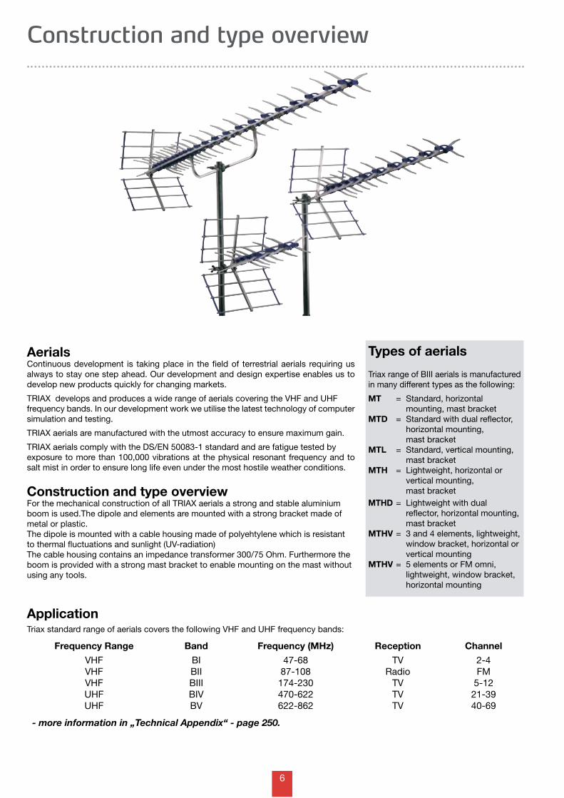
Frequency Range Band Frequency (MHz) Reception Channel
VHF BI 47-68 TV 2-4 VHF BII 87-108 Radio FM VHF BIII 174-230 TV 5-12 UHF BIV 470-622 TV 21-39 UHF BV 622-862 TV 40-69
- more information in „Technical Appendix“ - page 250.
ApplicationTriax standard range of aerials covers the following VHF and UHF frequency bands:
AerialsContinuous development is taking place in the field of terrestrial aerials requiring us always to stay one step ahead. Our development and design expertise enables us to develop new products quickly for changing markets.
TRIAX develops and produces a wide range of aerials covering the VHF and UHF frequency bands. In our development work we utilise the latest technology of computer simulation and testing.
TRIAX aerials are manufactured with the utmost accuracy to ensure maximum gain.
TRIAX aerials comply with the DS/EN 50083-1 standard and are fatigue tested by exposure to more than 100,000 vibrations at the physical resonant frequency and to salt mist in order to ensure long life even under the most hostile weather conditions.
Construction and type overviewFor the mechanical construction of all TRIAX aerials a strong and stable aluminium boom is used.The dipole and elements are mounted with a strong bracket made of metal or plastic.The dipole is mounted with a cable housing made of polyehtylene which is resistant to thermal fluctuations and sunlight (UV-radiation)The cable housing contains an impedance transformer 300/75 Ohm. Furthermore the boom is provided with a strong mast bracket to enable mounting on the mast without using any tools.
Types of aerials
Triax range of BIII aerials is manufactured in many different types as the following:
MT = Standard, horizontal mounting, mast bracketMTD = Standard with dual reflector, horizontal mounting, mast bracketMTL = Standard, vertical mounting, mast bracketMTH = Lightweight, horizontal or vertical mounting, mast bracketMTHD = Lightweight with dual reflector, horizontal mounting, mast bracketMTHV = 3 and 4 elements, lightweight, window bracket, horizontal or vertical mountingMTHV = 5 elements or FM omni, lightweight, window bracket, horizontal mounting
7
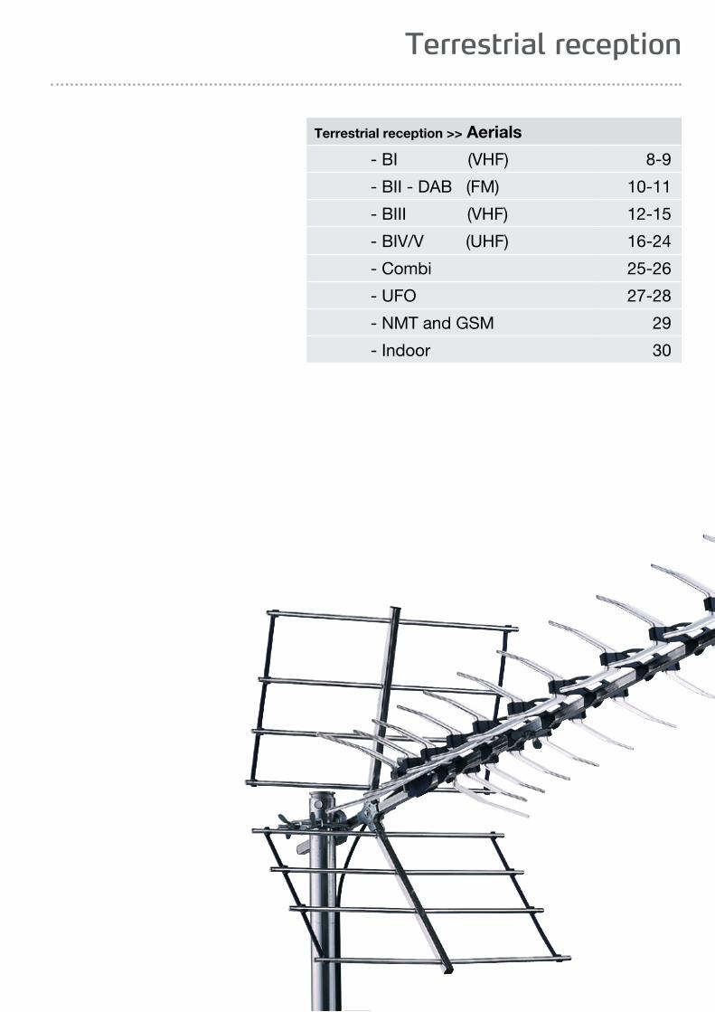
Terrestrial reception >> Aerials
- BI (VHF) 8-9
- BII - DAB (FM) 10-11
- BIII (VHF) 12-15
- BIV/V (UHF) 16-24
- Combi 25-26
- UFO 27-28
- NMT and GSM 29
- Indoor 30
Terrestrial reception
8
2
4
6
8
10
12
14
16
18
Channel
Gain
Ch. 3
2
4
6
8
10
12
14
16
18
Channel
Gain
Ch. 2
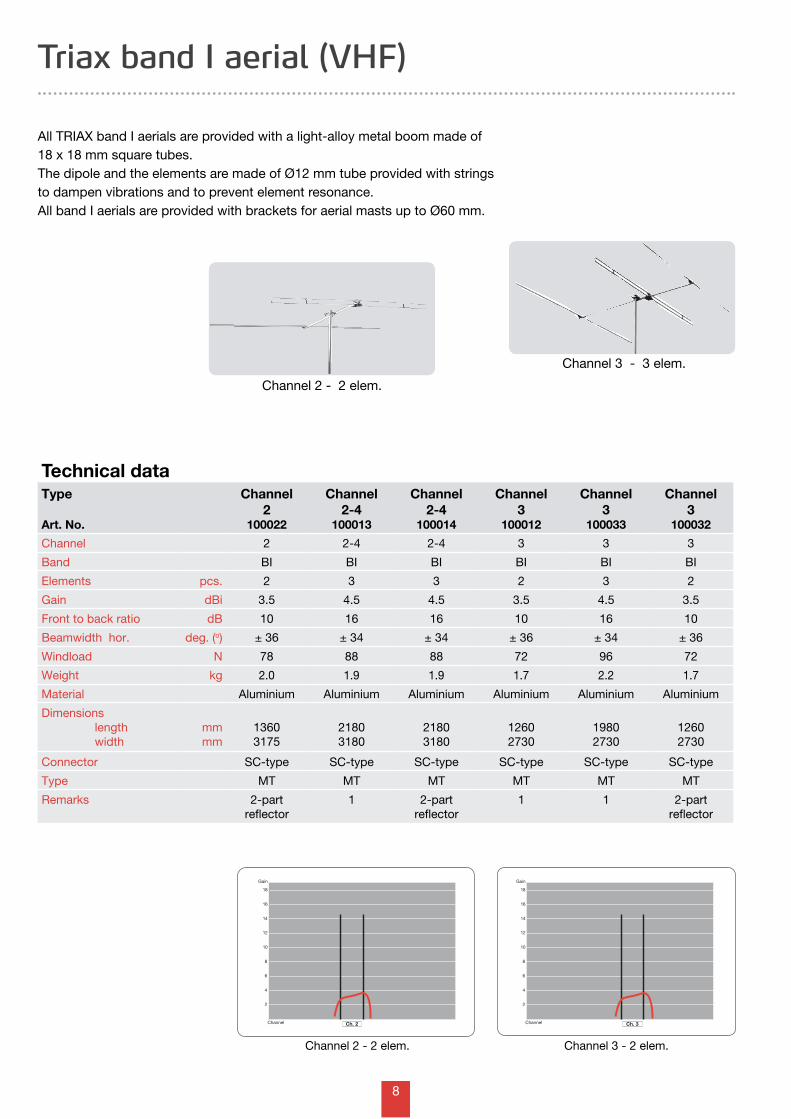
Triax band I aerial (VHF)
Type
Art. No.
Channel 2
100022
Channel 2-4
100013
Channel 2-4
100014
Channel 3
100012
Channel 3
100033
Channel 3
100032
Channel 2 2-4 2-4 3 3 3
Band BI BI BI BI BI BI
Elements pcs. 2 3 3 2 3 2
Gain dBi 3.5 4.5 4.5 3.5 4.5 3.5
Front to back ratio dB 10 16 16 10 16 10
Beamwidth hor. deg. (o) ± 36 ± 34 ± 34 ± 36 ± 34 ± 36
Windload N 78 88 88 72 96 72
Weight kg 2.0 1.9 1.9 1.7 2.2 1.7
Material Aluminium Aluminium Aluminium Aluminium Aluminium Aluminium
Dimensions length width
mmmm
13603175
21803180
21803180
12602730
19802730
12602730
Connector SC-type SC-type SC-type SC-type SC-type SC-type
Type MT MT MT MT MT MT
Remarks 2-part reflector
1 2-part reflector
1 1 2-part reflector
Technical data
All TRIAX band I aerials are provided with a light-alloy metal boom made of 18 x 18 mm square tubes.The dipole and the elements are made of Ø12 mm tube provided with strings to dampen vibrations and to prevent element resonance.All band I aerials are provided with brackets for aerial masts up to Ø60 mm.
Channel 3 - 2 elem.Channel 2 - 2 elem.
Channel 2 - 2 elem.
Channel 3 - 3 elem.
9
2
4
6
8
10
12
14
16
18
Channel
Gain
Ch. 4
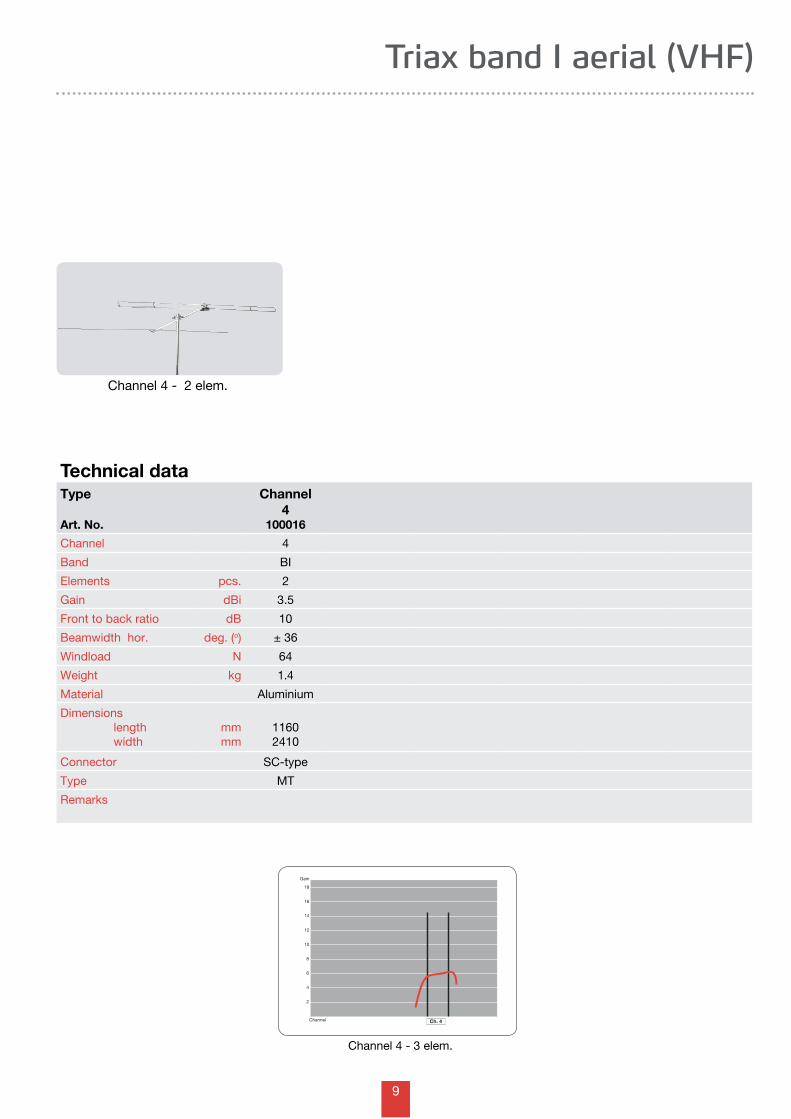
Triax band I aerial (VHF)
Type
Art. No.
Channel 4
100016
Channel 4
Band BI
Elements pcs. 2
Gain dBi 3.5
Front to back ratio dB 10
Beamwidth hor. deg. (o) ± 36
Windload N 64
Weight kg 1.4
Material Aluminium
Dimensions length width
mmmm
11602410
Connector SC-type
Type MT
Remarks
Technical data
Channel 4 - 3 elem.
Channel 4 - 2 elem.
10
88 MHz 108 MHzFrequenze
Gain
2
4
6
8
10
12
- 2
0
- 4
FM 5
88 MHz 108 MHz
Gain
2
4
6
8
10
12
-2
0
-4
FM 3
Frequenze
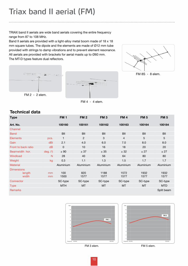
Triax band II aerial (FM)
Type
Art. No.
FM 1
100160
FM 2
100161
FM 3
100162
FM 4
100163
FM 5
100164
FM 5
100184
Channel
Band BII BII BII BII BII BII
Elements pcs. 1 2 3 4 5 5
Gain dBi 2.1 4.0 6.0 7.0 8.0 8.0
Front to back ratio dB 0 10 16 18 20 20
Beamwidth hor. deg. (o) ± 90 ± 37 ± 35 ± 32 ± 27 ± 27
Windload N 28 40 56 64 80 80
Weight kg 0.3 1.1 1.3 1.5 1.7 1.7
Material Aluminium Aluminium Aluminium Aluminium Aluminium Aluminium
Dimensions length width
mmmm
1001500
8201577
11881577
15721577
19321577
19321577
Connector SC-type SC-type SC-type SC-type SC-type SC-type
Type MTH MT MT MT MT MTD
Remarks Split beam
Technical data
TRIAX band II aerials are wide band aerials covering the entire frequency range from 87 to 108 MHz.Band II aerials are provided with a light-alloy metal boom made of 18 x 18 mm square tubes. The dipole and the elements are made of Ø12 mm tube provided with strings to damp vibrations and to prevent element resonance.All aerials are provided with brackets for aerial masts up to Ø60 mm.The MT-D types feature dual reflectors.
FM 5 elem.
FM 2 - 2 elem.
FM 8S - 8 elem.
FM 4 - 4 elem.
FM 3 elem.
11
88 MHz 108 MHzFrequenze
Gain
2
4
6
8
10
12
-2
0
-4
FM 8-S
88 MHz 108 MHzFrequenze
Gain
2
4
6
8
10
12
-2
0
-4
FMOmni
200 MHz 260 MHz
Gain
2
4
6
8
10
12
-2
0
-4
DAB 5
Frequenze
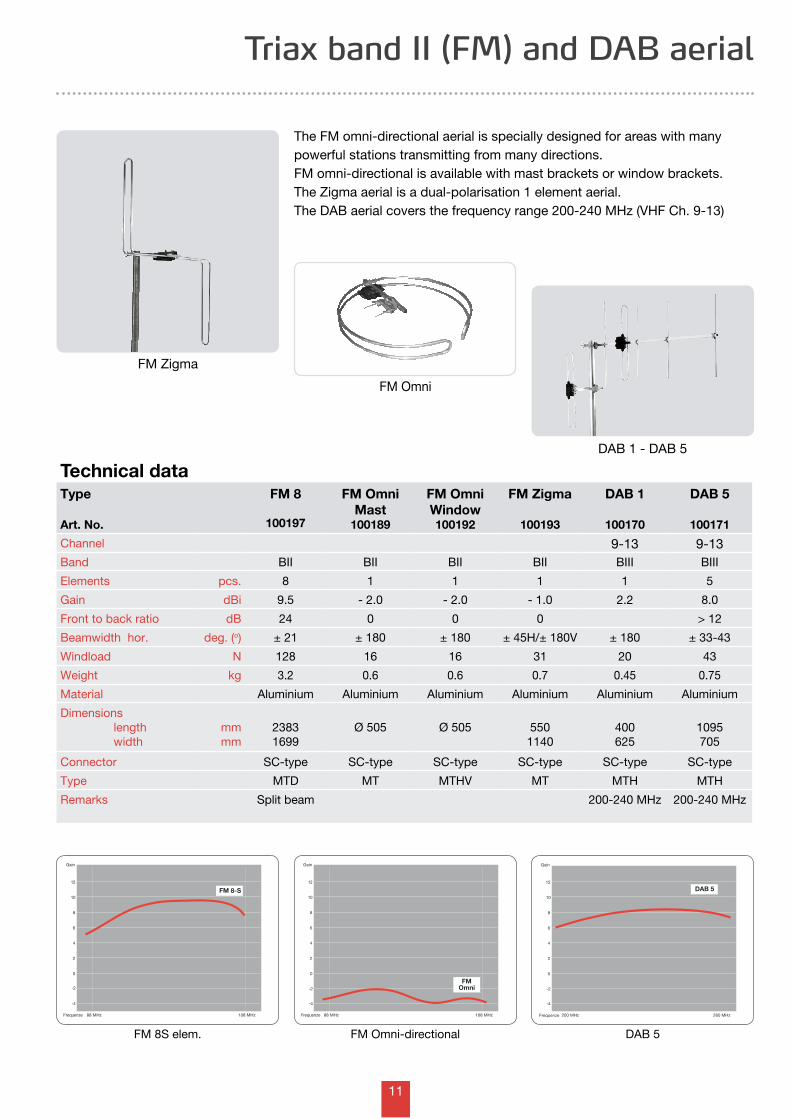
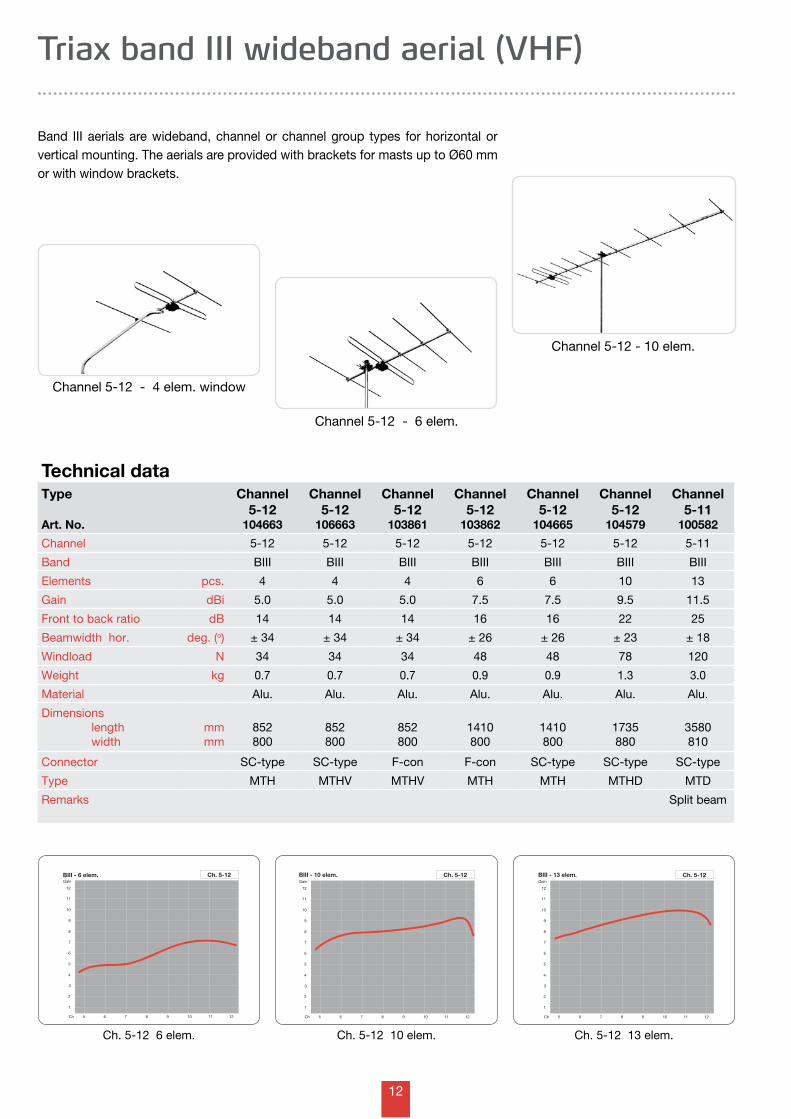
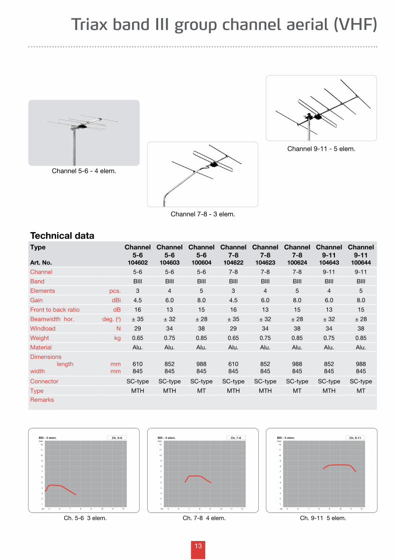
The FM omni-directional aerial is specially designed for areas with many powerful stations transmitting from many directions. FM omni-directional is available with mast brackets or window brackets.The Zigma aerial is a dual-polarisation 1 element aerial.The DAB aerial covers the frequency range 200-240 MHz (VHF Ch. 9-13)
Triax band II (FM) and DAB aerial
FM 8S elem.
Type
Art. No.
FM 8
100197
FM Omni Mast
100189
FM Omni Window100192
FM Zigma
100193
DAB 1
100170
DAB 5
100171
Channel 9-13 9-13Band BII BII BII BII BIII BIII
Elements pcs. 8 1 1 1 1 5
Gain dBi 9.5 - 2.0 - 2.0 - 1.0 2.2 8.0
Front to back ratio dB 24 0 0 0 > 12
Beamwidth hor. deg. (o) ± 21 ± 180 ± 180 ± 45H/± 180V ± 180 ± 33-43
Windload N 128 16 16 31 20 43
Weight kg 3.2 0.6 0.6 0.7 0.45 0.75
Material Aluminium Aluminium Aluminium Aluminium Aluminium Aluminium
Dimensions length width
mmmm
23831699
Ø 505 Ø 505 5501140
400625
1095705
Connector SC-type SC-type SC-type SC-type SC-type SC-type
Type MTD MT MTHV MT MTH MTH
Remarks Split beam 200-240 MHz 200-240 MHz
Technical dataDAB 1 - DAB 5
FM Zigma
FM Omni-directional DAB 5
FM Omni
12
BIII - 6 elem.Gain
5 6 7 8 9 10 11 12Ch
1
3
2
6
7
8
10
11
4
5
9
12
Ch. 5-12 BIII - 13 elem.Gain
5 6 7 8 9 10 11 12Ch
1
3
2
6
7
8
10
11
4
5
9
12
Ch. 5-12BIII - 10 elem.Gain
5 6 7 8 9 10 11 12Ch
1
3
2
6
7
8
10
11
4
5
9
12
Ch. 5-12
Triax band III wideband aerial (VHF)
Type
Art. No.
Channel 5-12
104663
Channel 5-12
106663
Channel 5-12
103861
Channel 5-12
103862
Channel 5-12
104665
Channel 5-12
104579
Channel 5-11
100582
Channel 5-12 5-12 5-12 5-12 5-12 5-12 5-11
Band BIII BIII BIII BIII BIII BIII BIII
Elements pcs. 4 4 4 6 6 10 13
Gain dBi 5.0 5.0 5.0 7.5 7.5 9.5 11.5
Front to back ratio dB 14 14 14 16 16 22 25
Beamwidth hor. deg. (o) ± 34 ± 34 ± 34 ± 26 ± 26 ± 23 ± 18
Windload N 34 34 34 48 48 78 120
Weight kg 0.7 0.7 0.7 0.9 0.9 1.3 3.0
Material Alu. Alu. Alu. Alu. Alu. Alu. Alu.
Dimensions length width
mmmm
852800
852800
852800
1410800
1410800
1735880
3580810
Connector SC-type SC-type F-con F-con SC-type SC-type SC-type
Type MTH MTHV MTHV MTH MTH MTHD MTD
Remarks Split beam
Technical data
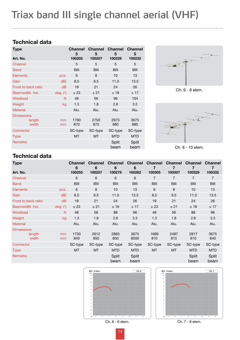
Band III aerials are wideband, channel or channel group types for horizontal or vertical mounting. The aerials are provided with brackets for masts up to Ø60 mm or with window brackets.
Ch. 5-12 13 elem.Ch. 5-12 10 elem.
Channel 5-12 - 4 elem. window
Channel 5-12 - 10 elem.
Channel 5-12 - 6 elem.
Ch. 5-12 6 elem.
13
BIII - 3 elem.Gain
5 6 7 8 9 10 11 12Ch
1
3
2
6
7
8
10
11
4
5
9
12
Ch. 5-6 BIII - 5 elem.Gain
5 6 7 8 9 10 11 12Ch
1
3
2
6
7
8
10
11
4
5
9
12
Ch. 9-11BIII - 4 elem.Gain
5 6 7 8 9 10 11 12Ch
1
3
2
6
7
8
10
11
4
5
9
12
Ch. 7-8
Triax band III group channel aerial (VHF)
Channel 7-8 - 3 elem.
Channel 5-6 - 4 elem.
Channel 9-11 - 5 elem.
Type
Art. No.
Channel 5-6
104602
Channel 5-6
104603
Channel 5-6
100604
Channel 7-8
104622
Channel 7-8
104623
Channel 7-8
100624
Channel 9-11
104643
Channel 9-11
100644
Channel 5-6 5-6 5-6 7-8 7-8 7-8 9-11 9-11
Band BIII BIII BIII BIII BIII BIII BIII BIII
Elements pcs. 3 4 5 3 4 5 4 5
Gain dBi 4.5 6.0 8.0 4.5 6.0 8.0 6.0 8.0
Front to back ratio dB 16 13 15 16 13 15 13 15
Beamwidth hor. deg. (o) ± 35 ± 32 ± 28 ± 35 ± 32 ± 28 ± 32 ± 28
Windload N 29 34 38 29 34 38 34 38
Weight kg 0.65 0.75 0.85 0.65 0.75 0.85 0.75 0.85
Material Alu. Alu. Alu. Alu. Alu. Alu. Alu. Alu.
Dimensions length width
mmmm
610845
852845
988845
610845
852845
988845
852845
988845
Connector SC-type SC-type SC-type SC-type SC-type SC-type SC-type SC-type
Type MTH MTH MT MTH MTH MT MTH MT
Remarks
Technical data
Ch. 9-11 5 elem.Ch. 7-8 4 elem.Ch. 5-6 3 elem.
14
BIII - 8 elem.Gain
5 6 7 8 9 10 11 12Ch
1
3
2
6
7
8
10
11
4
5
9
12
Ch. 7BIII - 6 elem.Gain
5 6 7 8 9 10 11 12Ch
1
3
2
6
7
8
10
11
4
5
9
12
Ch. 6
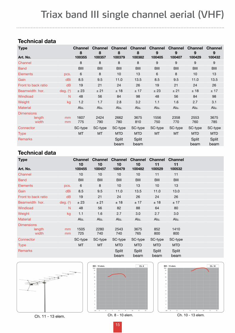
Triax band III single channel aerial (VHF)
Type
Art. No.
Channel 6
100255
Channel 6
100257
Channel 6
100279
Channel 6
100282
Channel 7
100305
Channel 7
100307
Channel 7
100329
Channel 7
100332
Channel 6 6 6 6 7 7 7 7
Band BIII BIII BIII BIII BIII BIII BIII BIII
Elements pcs. 6 8 10 13 6 8 10 13
Gain dBi 8.5 9.5 11.0 13.5 8.5 9.5 11.0 13.5
Front to back ratio dB 19 21 24 26 19 21 24 26
Beamwidth hor. deg. (o) ± 23 ± 21 ± 18 ± 17 ± 23 ± 21 ± 18 ± 17
Windload N 48 56 88 96 48 56 88 96
Weight kg 1.3 1.8 2.8 3.3 1.3 1.8 2.8 3.3
Material Alu. Alu. Alu. Alu. Alu. Alu. Alu. Alu.
Dimensions length width
mmmm
1730840
2612850
2883850
36758500
1689810
2487815
2817810
3675840
Connector SC-type SC-type SC-type SC-type SC-type SC-type SC-type SC-type
Type MT MT MTD MTD MT MT MTD MTD
Remarks Split beam
Split beam
Split beam
Split beam
Technical data
Ch. 7 - 8 elem.Ch. 6 - 6 elem.
Type
Art. No.
Channel 5
100205
Channel 5
100207
Channel 5
100229
Channel 5
100232
Channel 5 5 5 5
Band BIII BIII BIII BIII
Elements pcs. 6 8 10 13
Gain dBi 8.5 9.5 11.0 13.5
Front to back ratio dB 19 21 24 26
Beamwidth hor. deg. (o) ± 23 ± 21 ± 18 ± 17
Windload N 48 56 96 104
Weight kg 1.3 1.8 2.8 3.3
Material Alu. Alu. Alu. Alu.
Dimensions length width
mmmm
1790870
2750875
2973880
3675880
Connector SC-type SC-type SC-type SC-type
Type MT MT MTD MTD
Remarks Split beam
Split beam
Technical data
Ch. 6 - 8 elem.
Ch. 8 - 10 elem.
15
BIII - 13 elem.Gain
5 6 7 8 9 10 11 12Ch
1
3
2
6
7
8
10
11
4
5
9
12
Ch. 10BIII - 10 elem.Gain
5 6 7 8 9 10 11 12Ch
1
3
2
6
7
8
10
11
4
5
9
12
Ch. 8
Triax band III single channel aerial (VHF)
Technical dataType
Art. No.
Channel 10
100455
Channel 10
100457
Channel 10
100479
Channel 10
100482
Channel 11
100529
Channel 11
100532
Channel 10 10 10 10 11 11
Band BIII BIII BIII BIII BIII BIII
Elements pcs. 6 8 10 13 10 13
Gain dBi 8.5 9.5 11.0 13.5 11.0 13.0
Front to back ratio dB 19 21 24 26 24 26
Beamwidth hor. deg. (o) ± 23 ± 21 ± 18 ± 17 ± 18 ± 17
Windload N 48 56 82 88 64 80
Weight kg 1.1 1.6 2.7 3.0 2.7 3.0
Material Alu. Alu. Alu. Alu. Alu. Alu.
Dimensions length width
mmmm
1505725
2280740
2543740
3675765
852800
1410800
Connector SC-type SC-type SC-type SC-type SC-type SC-type
Type MT MT MTD MTD MTD MTD
Remarks Split beam
Split beam
Split beam
Split beam
Ch. 10 - 13 elem.Ch. 8 - 10 elem.
Technical dataType
Art. No.
Channel 8
100355
Channel 8
100357
Channel 8
100379
Channel 8
100382
Channel 9
100405
Channel 9
100407
Channel 9
100429
Channel 9
100432
Channel 8 8 8 8 9 9 9 9
Band BIII BIII BIII BIII BIII BIII BIII BIII
Elements pcs. 6 8 10 13 6 8 10 13
Gain dBi 8.5 9.5 11.0 13.5 8.5 9.5 11.0 13.5
Front to back ratio dB 19 21 24 26 19 21 24 26
Beamwidth hor. deg. (o) ± 23 ± 21 ± 18 ± 17 ± 23 ± 21 ± 18 ± 17
Windload N 48 56 84 98 48 56 84 98
Weight kg 1.2 1.7 2.8 3.2 1.1 1.6 2.7 3.1
Material Alu. Alu. Alu. Alu. Alu. Alu. Alu. Alu.
Dimensions length width
mmmm
1607775
2424790
2662780
3675810
1556750
2358770
2553760
3675785
Connector SC-type SC-type SC-type SC-type SC-type SC-type SC-type SC-type
Type MT MT MTD MTD MT MT MTD MTD
Remarks Split beam
Split beam
Split beam
Split beam
Ch. 11 - 13 elem.
16
21 31 41 51 61
2
4
6
8
10
12
14
16
18
69Ch
Gain
Ch. 21-69
Yagi 10 Elm.
21 31 41 51 61
2
4
6
8
10
12
14
16
18
69Ch
Gain
Ch. 21-37 Ch. 21-69
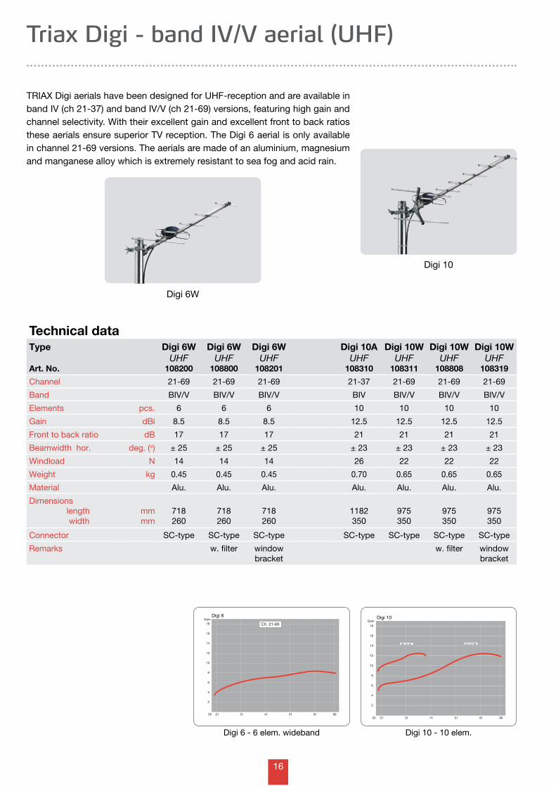
Triax Digi - band IV/V aerial (UHF)
Type
Art. No.
Digi 6WUHF
108200
Digi 6W UHF
108800
Digi 6W UHF
108201
Digi 10AUHF
108310
Digi 10WUHF
108311
Digi 10WUHF
108808
Digi 10WUHF
108319
Channel 21-69 21-69 21-69 21-37 21-69 21-69 21-69
Band BIV/V BIV/V BIV/V BIV BIV/V BIV/V BIV/V
Elements pcs. 6 6 6 10 10 10 10
Gain dBi 8.5 8.5 8.5 12.5 12.5 12.5 12.5
Front to back ratio dB 17 17 17 21 21 21 21
Beamwidth hor. deg. (o) ± 25 ± 25 ± 25 ± 23 ± 23 ± 23 ± 23
Windload N 14 14 14 26 22 22 22
Weight kg 0.45 0.45 0.45 0.70 0.65 0.65 0.65
Material Alu. Alu. Alu. Alu. Alu. Alu. Alu.
Dimensions length width
mmmm
718260
718260
718260
1182350
975350
975350
975350
Connector SC-type SC-type SC-type SC-type SC-type SC-type SC-type
Remarks w. filter window bracket
w. filter window bracket
Technical data
TRIAX Digi aerials have been designed for UHF-reception and are available in band IV (ch 21-37) and band IV/V (ch 21-69) versions, featuring high gain and channel selectivity. With their excellent gain and excellent front to back ratios these aerials ensure superior TV reception. The Digi 6 aerial is only available in channel 21-69 versions. The aerials are made of an aluminium, magnesium and manganese alloy which is extremely resistant to sea fog and acid rain.
Digi 10 - 10 elem.
Digi 6W
Digi 10
Digi 6 - 6 elem. wideband
Digi 6 Digi 10
17
Yagi 14 Elm.
21 31 41 51 61
2
4
6
8
10
12
14
16
18
69Ch
Gain Ch. 21-69Ch.
21-37
Digi 343 - 50 Elm.
21 31 41 51 61
2
4
6
8
10
12
14
16
18
69Ch
Gain Ch. 21-69
Digi 343 - 50 Elm.
21 31 41 51 61
2
4
6
8
10
12
14
16
18
69Ch
Gain Ch. 21-69
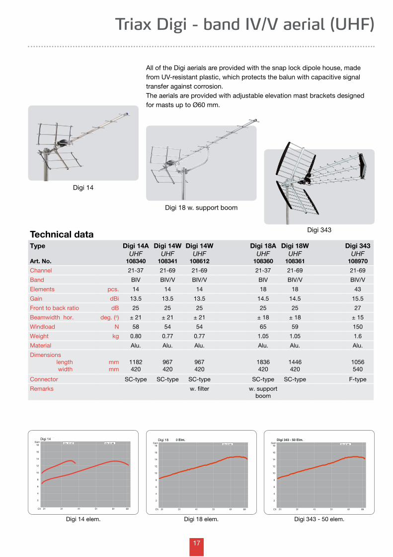
Triax Digi - band IV/V aerial (UHF)
Technical dataType
Art. No.
Digi 14AUHF
108340
Digi 14WUHF
108341
Digi 14WUHF
108612
Digi 18AUHF
108360
Digi 18WUHF
108361
Digi 343UHF
108970
Channel 21-37 21-69 21-69 21-37 21-69 21-69
Band BIV BIV/V BIV/V BIV BIV/V BIV/V
Elements pcs. 14 14 14 18 18 43
Gain dBi 13.5 13.5 13.5 14.5 14.5 15.5
Front to back ratio dB 25 25 25 25 25 27
Beamwidth hor. deg. (o) ± 21 ± 21 ± 21 ± 18 ± 18 ± 15
Windload N 58 54 54 65 59 150
Weight kg 0.80 0.77 0.77 1.05 1.05 1.6
Material Alu. Alu. Alu. Alu. Alu. Alu.
Dimensions length width
mmmm
1182420
967420
967420
1836420
1446420
1056540
Connector SC-type SC-type SC-type SC-type SC-type F-type
Remarks w. filter w. supportboom
Digi 14
Digi 14 elem.
Digi 14
All of the Digi aerials are provided with the snap lock dipole house, made from UV-resistant plastic, which protects the balun with capacitive signal transfer against corrosion.The aerials are provided with adjustable elevation mast brackets designed for masts up to Ø60 mm.
Digi 18 w. support boom
Digi 18 elem.
Digi 18
Digi 343
Digi 343 - 50 elem.
18
Yagi 15
21 31 41 51 61
2
4
6
8
10
12
14
16
18
69Ch
Gain Ch. 21-69Ch.
21-47
21 31 41 51 61
2
4
6
8
10
12
14
16
18
69Ch
Gain
Ch. 21-69
Yagi 10 Elm.
21 31 41 51 61
2
4
6
8
10
12
14
16
18
69Ch
Gain
Ch. 21-37 Ch. 21-69
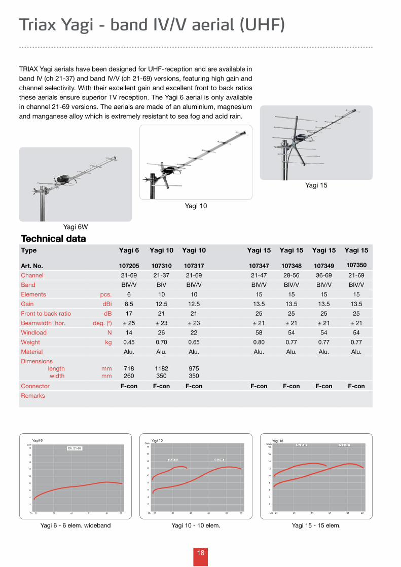
Triax Yagi - band IV/V aerial (UHF)
Technical data
Yagi 15
TRIAX Yagi aerials have been designed for UHF-reception and are available in band IV (ch 21-37) and band IV/V (ch 21-69) versions, featuring high gain and channel selectivity. With their excellent gain and excellent front to back ratios these aerials ensure superior TV reception. The Yagi 6 aerial is only available in channel 21-69 versions. The aerials are made of an aluminium, magnesium and manganese alloy which is extremely resistant to sea fog and acid rain.
Type
Art. No.
Yagi 6
107205
Yagi 10
107310
Yagi 10
107317
Yagi 15
107347
Yagi 15
107348
Yagi 15
107349
Yagi 15
107350
Channel 21-69 21-37 21-69 21-47 28-56 36-69 21-69
Band BIV/V BIV BIV/V BIV/V BIV/V BIV/V BIV/V
Elements pcs. 6 10 10 15 15 15 15
Gain dBi 8.5 12.5 12.5 13.5 13.5 13.5 13.5
Front to back ratio dB 17 21 21 25 25 25 25
Beamwidth hor. deg. (o) ± 25 ± 23 ± 23 ± 21 ± 21 ± 21 ± 21
Windload N 14 26 22 58 54 54 54
Weight kg 0.45 0.70 0.65 0.80 0.77 0.77 0.77
Material Alu. Alu. Alu. Alu. Alu. Alu. Alu.
Dimensions length width
mmmm
718260
1182350
975350
Connector F-con F-con F-con F-con F-con F-con F-con
Remarks
Technical data
Yagi 10 - 10 elem.
Yagi 6W
Yagi 10
Yagi 6 - 6 elem. wideband
YagiI 6 Yagi 10 Yagi 15
Yagi 15 - 15 elem.
19
Yagi 18 Elm.
21 31 41 51 61
2
4
6
8
10
12
14
16
18
69Ch
Gain Ch. 21-69Ch.
21-37
Yagi 18 single pack channelized aerials appear from the below table.
Triax Yagi - band IV/V aerial (UHF)
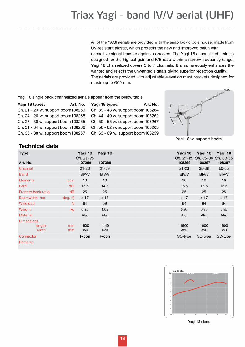
All of the YAGI aerials are provided with the snap lock dipole house, made from UV-resistant plastic, which protects the new and improved balun with capacitive signal transfer against corrosion. The Yagi 18 channelized aerial is designed for the highest gain and F/B ratio within a narrow frequency range. Yagi 18 channelized covers 3 to 7 channels. It simultaneously enhances the wanted and rejects the unwanted signals giving superior reception quality.The aerials are provided with adjustable elevation mast brackets designed for masts up to Ø60 mm.
Yagi 18 w. support boom
Technical data
Yagi 18 elem.
Type
Art. No.
Yagi 18 Ch. 21-23
107269
Yagi 18
107368
Yagi 18 Ch. 21-23
108269
Yagi 18 Ch. 35-38
108257
Yagi 18 Ch. 50-55
108267
Channel 21-23 21-69 21-23 35-38 50-55
Band BIV/V BIV/V BIV/V BIV/V BIV/V
Elements pcs. 18 18 18 18 18
Gain dBi 15.5 14.5 15.5 15.5 15.5
Front to back ratio dB 25 25 25 25 25
Beamwidth hor. deg. (o) ± 17 ± 18 ± 17 ± 17 ± 17
Windload N 64 59 64 64 64
Weight kg 0.95 1.05 0.95 0.95 0.95
Material Alu. Alu. Alu. Alu. Alu.
Dimensions length width
mmmm
1800350
1446420
1800350
1800350
1800350
Connector F-con F-con SC-type SC-type SC-type
Remarks
Yagi 18 types: Art. No.Ch. 21 - 23 w. support boom 108269Ch. 24 - 26 w. support boom 108268Ch. 27 - 30 w. support boom 108265Ch. 31 - 34 w. support boom 108266Ch. 35 - 38 w. support boom 108257
Yagi 18 types: Art. No.Ch. 39 - 43 w. support boom 108264Ch. 44 - 49 w. support boom 108262Ch. 50 - 55 w. support boom 108267Ch. 56 - 62 w. support boom 108263Ch. 63 - 69 w. support boom 108259
20
Unix 32 Elm.
21 31 41 51 61
2
4
6
8
10
12
14
16
18
69Ch
GainCh.
21-69
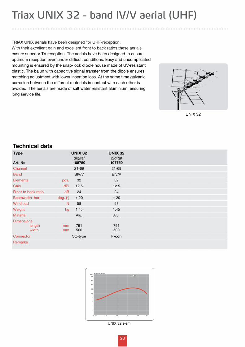
Triax UNIX 32 - band IV/V aerial (UHF)
TRIAX UNIX aerials have been designed for UHF-reception.With their excellent gain and excellent front to back ratios these aerials ensure superior TV reception. The aerials have been designed to ensure optimum reception even under difficult conditions. Easy and uncomplicated mounting is ensured by the snap-lock dipole house made of UV-resistant plastic. The balun with capacitive signal transfer from the dipole ensures matching adjustment with lower insertion loss. At the same time galvanic corrosion between the different materials in contact with each other is avoided. The aerials are made of salt water resistant aluminium, ensuring long service life.
Technical dataType
Art. No.
UNIX 32 digital108750
UNIX 32 digital107750
Channel 21-69 21-69
Band BIV/V BIV/V
Elements pcs. 32 32
Gain dBi 12.5 12.5
Front to back ratio dB 24 24
Beamwidth hor. deg. (o) ± 20 ± 20
Windload N 58 58
Weight kg 1.45 1.45
Material Alu. Alu.
Dimensions length width
mmmm
791500
791500
Connector SC-type F-con
Remarks
UNIX 32
UNIX 32 elem.
21
Unix 52 Elm.
21 31 41 51 61
2
4
6
8
10
12
14
16
18
69Ch
Gain
Ch. 21-40 Ch. 21-50 Ch.
21-69
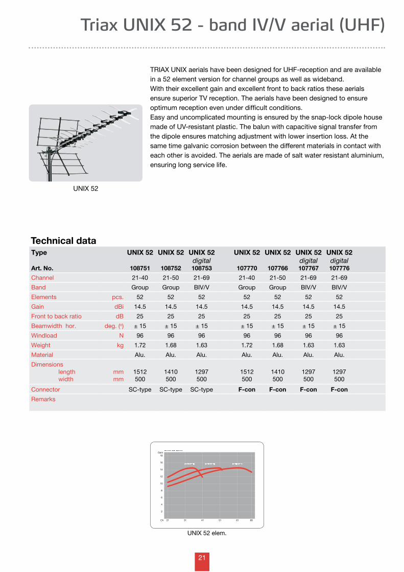
Triax UNIX 52 - band IV/V aerial (UHF)
TRIAX UNIX aerials have been designed for UHF-reception and are available in a 52 element version for channel groups as well as wideband.With their excellent gain and excellent front to back ratios these aerials ensure superior TV reception. The aerials have been designed to ensure optimum reception even under difficult conditions. Easy and uncomplicated mounting is ensured by the snap-lock dipole house made of UV-resistant plastic. The balun with capacitive signal transfer from the dipole ensures matching adjustment with lower insertion loss. At the same time galvanic corrosion between the different materials in contact with each other is avoided. The aerials are made of salt water resistant aluminium, ensuring long service life.
Technical dataType
Art. No.
UNIX 52
108751
UNIX 52
108752
UNIX 52 digital108753
UNIX 52
107770
UNIX 52
107766
UNIX 52 digital107767
UNIX 52 digital107776
Channel 21-40 21-50 21-69 21-40 21-50 21-69 21-69
Band Group Group BIV/V Group Group BIV/V BIV/V
Elements pcs. 52 52 52 52 52 52 52
Gain dBi 14.5 14.5 14.5 14.5 14.5 14.5 14.5
Front to back ratio dB 25 25 25 25 25 25 25
Beamwidth hor. deg. (o) ± 15 ± 15 ± 15 ± 15 ± 15 ± 15 ± 15
Windload N 96 96 96 96 96 96 96
Weight kg 1.72 1.68 1.63 1.72 1.68 1.63 1.63
Material Alu. Alu. Alu. Alu. Alu. Alu. Alu.
Dimensions length width
mmmm
1512500
1410500
1297500
1512500
1410500
1297500
1297500
Connector SC-type SC-type SC-type F-con F-con F-con F-con
Remarks
UNIX 52
UNIX 52 elem.
22
Unix 100 Elm.
21 31 41 51 61
2
4
6
8
10
12
14
16
18
69Ch.
GainCh. 21-40 Ch. 21-50 Ch.
21-69
Type
Art. No.
UNIX 100
108754
UNIX 100
108755
UNIX 100 digital108756
UNIX 100
107768
UNIX 100 digital107769
UNIX 100 digital107756
Channel 21-40 21-50 21-69 21-50 21-69 21-69
Band Group Group BIV/V Group Group BIV/V
Elements pcs. 100 100 100 100 100 100
Gain dBi 17.0 17.0 17.0 17.0 17.0 17.0
Front to back ratio dB 27 27 27 27 27 27
Beamwidth hor. deg. (o) ± 11 ± 11 ± 11 ± 11 ± 11 ± 11
Windload N 176 152 152 176 152 152
Weight kg 3.19 2.50 2.46 2.50 2.46 2.46
Material Alu. Alu. Alu. Alu. Alu. Alu.
Dimensions length width
mmmm
2887500
2332500
2257500
2332500
2257500
2257500
Connector SC-type SC-type SC-type F-con F-con F-con
Remarks
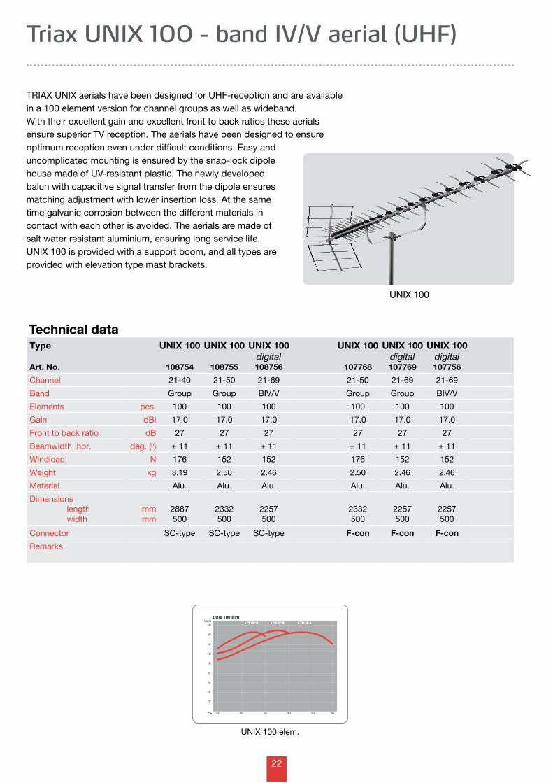
Triax UNIX 100 - band IV/V aerial (UHF)
TRIAX UNIX aerials have been designed for UHF-reception and are available in a 100 element version for channel groups as well as wideband.With their excellent gain and excellent front to back ratios these aerials ensure superior TV reception. The aerials have been designed to ensure optimum reception even under difficult conditions. Easy and uncomplicated mounting is ensured by the snap-lock dipole house made of UV-resistant plastic. The newly developed balun with capacitive signal transfer from the dipole ensures matching adjustment with lower insertion loss. At the same time galvanic corrosion between the different materials in contact with each other is avoided. The aerials are made of salt water resistant aluminium, ensuring long service life.UNIX 100 is provided with a support boom, and all types are provided with elevation type mast brackets.
Technical data
UNIX 100
UNIX 100 elem.
23
Gain for stacking the BB Grid aerials
0123456789
1011121314151617181920
21 23 25 27 29 31 33 35 37 39 41 43 45 47 49 51 53 55 57 59 61 63 65 67 69Ch
Gai
n [d
Bd]
single BBGrid
2 stack
4 stack
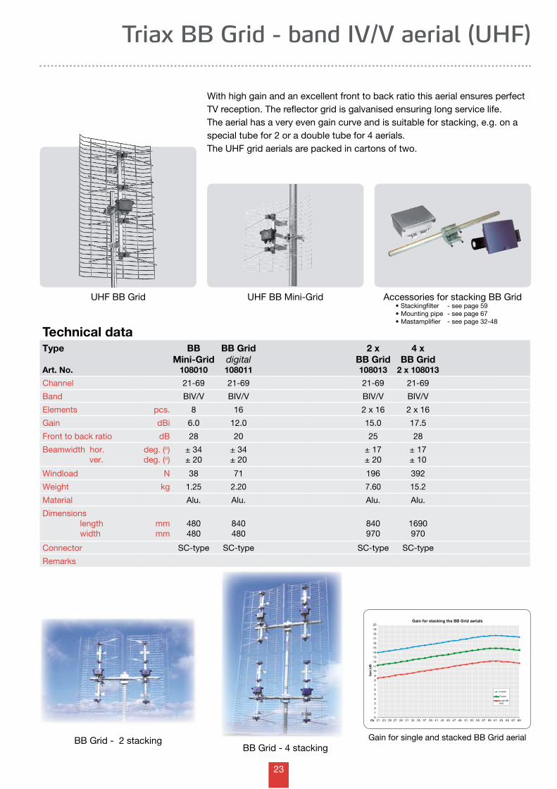
Triax BB Grid - band IV/V aerial (UHF)
Type
Art. No.
BB Mini-Grid
108010
BB Griddigital108011
2 x BB Grid108013
4 x BB Grid
2 x 108013
Channel 21-69 21-69 21-69 21-69
Band BIV/V BIV/V BIV/V BIV/V
Elements pcs. 8 16 2 x 16 2 x 16
Gain dBi 6.0 12.0 15.0 17.5
Front to back ratio dB 28 20 25 28
Beamwidth hor. ver.
deg. (o)deg. (o)
± 34± 20
± 34± 20
± 17± 20
± 17± 10
Windload N 38 71 196 392
Weight kg 1.25 2.20 7.60 15.2
Material Alu. Alu. Alu. Alu.
Dimensions length width
mmmm
480480
840480
840970
1690970
Connector SC-type SC-type SC-type SC-type
Remarks
Technical data
With high gain and an excellent front to back ratio this aerial ensures perfect TV reception. The reflector grid is galvanised ensuring long service life.The aerial has a very even gain curve and is suitable for stacking, e.g. on a special tube for 2 or a double tube for 4 aerials.The UHF grid aerials are packed in cartons of two.
Gain for single and stacked BB Grid aerial
UHF BB Grid Accessories for stacking BB Grid•Stackingfilter -seepage59•Mountingpipe-seepage67•Mastamplifier -seepage32-48
BB Grid - 4 stacking
UHF BB Mini-Grid
BB Grid - 2 stacking
24
Log- 32 elem.Gain
2
6
8
10
4
12
21 31 41 51 61 69Ch
Ch. 21-69Ch. 5-12
02 04 05 12Ch
Gain
2
6
8
10
4
12
Log- 30 elem.
21 31 41 51 61 69Ch
Gain
2
6
8
10
4
12
Ch. 21-69
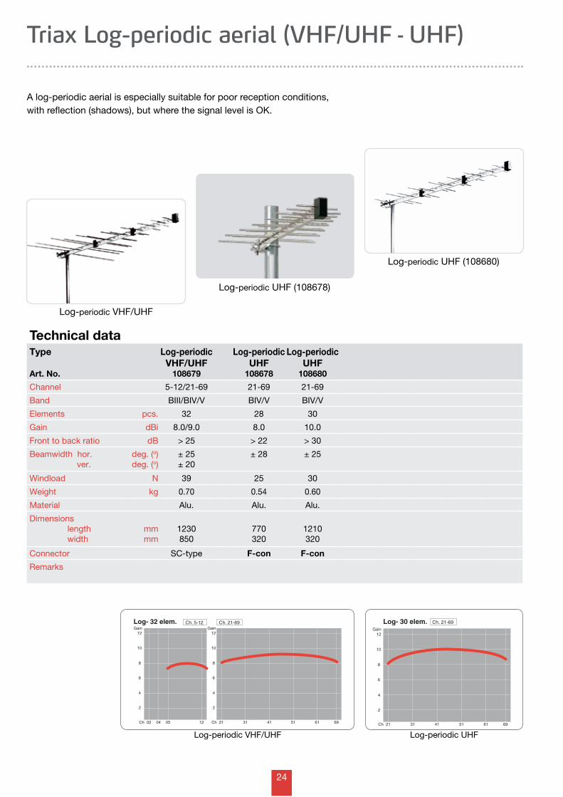
A log-periodic aerial is especially suitable for poor reception conditions, with reflection (shadows), but where the signal level is OK.
Triax Log-periodic aerial (VHF/UHF - UHF)
Log-periodic VHF/UHF
Log-periodic UHF (108680)
Type
Art. No.
Log-periodic VHF/UHF
108679
Log-periodic UHF
108678
Log-periodic UHF
108680
Channel 5-12/21-69 21-69 21-69
Band BIII/BIV/V BIV/V BIV/V
Elements pcs. 32 28 30
Gain dBi 8.0/9.0 8.0 10.0
Front to back ratio dB > 25 > 22 > 30
Beamwidth hor. ver.
deg. (o)deg. (o)
± 25± 20
± 28 ± 25
Windload N 39 25 30
Weight kg 0.70 0.54 0.60
Material Alu. Alu. Alu.
Dimensions length width
mmmm
1230850
770320
1210320
Connector SC-type F-con F-con
Remarks
Technical data
Log-periodic UHFLog-periodic VHF/UHF
Log-periodic UHF (108678)
25
Combi 13 Ch. 2-4/5-12
21 31 41 51 61
2
4
6
8
10
12
14
16
18
69Ch
Gain
02 04 05 12
2
4
6
8
10
12
14
16
18
Ch
GainCh. 21-60Combi 1/6 Ch. 2-4/5-12
21 31 41 51 61
2
4
6
8
10
12
14
16
18
69Ch
Gain
02 04 05 12
2
4
6
8
10
12
14
16
18
Ch
GainCh. 21-69
21 31 41 51 61
2
4
6
8
10
12
14
16
18
69Ch
Gain
02 04 05 12
2
4
6
8
10
12
14
16
18
Ch
Gain
Ch.
5-12 Ch. 21-69Combi 12
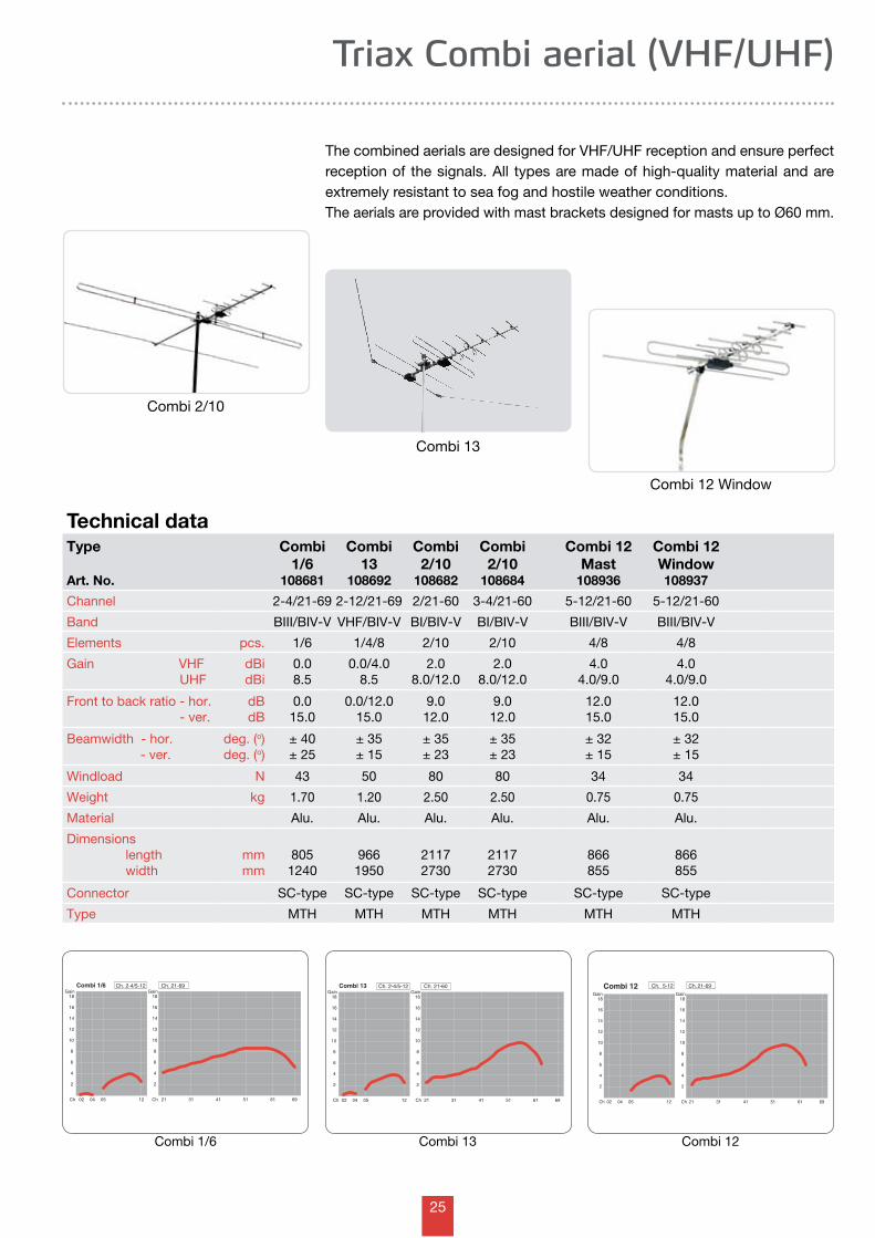
Triax Combi aerial (VHF/UHF)
Type
Art. No.
Combi 1/6
108681
Combi 13
108692
Combi 2/10
108682
Combi 2/10
108684
Combi 12 Mast
108936
Combi 12 Window108937
Channel 2-4/21-69 2-12/21-69 2/21-60 3-4/21-60 5-12/21-60 5-12/21-60
Band BIII/BIV-V VHF/BIV-V BI/BIV-V BI/BIV-V BIII/BIV-V BIII/BIV-V
Elements pcs. 1/6 1/4/8 2/10 2/10 4/8 4/8
Gain VHF UHF
dBidBi
0.08.5
0.0/4.08.5
2.08.0/12.0
2.08.0/12.0
4.04.0/9.0
4.04.0/9.0
Front to back ratio - hor. - ver.
dBdB
0.015.0
0.0/12.015.0
9.012.0
9.012.0
12.015.0
12.015.0
Beamwidth - hor. - ver.
deg. (o)deg. (o)
± 40± 25
± 35± 15
± 35± 23
± 35± 23
± 32± 15
± 32± 15
Windload N 43 50 80 80 34 34
Weight kg 1.70 1.20 2.50 2.50 0.75 0.75
Material Alu. Alu. Alu. Alu. Alu. Alu.
Dimensions length width
mmmm
8051240
9661950
21172730
21172730
866855
866855
Connector SC-type SC-type SC-type SC-type SC-type SC-type
Type MTH MTH MTH MTH MTH MTH
Technical data
The combined aerials are designed for VHF/UHF reception and ensure perfect reception of the signals. All types are made of high-quality material and are extremely resistant to sea fog and hostile weather conditions.The aerials are provided with mast brackets designed for masts up to Ø60 mm.
Combi 2/10
Combi 12 Window
Combi 12Combi 13
Combi 13
Combi 1/6
26
Combi 20Gain
2
6
8
10
4
12Gain
21 31 41 51 61 69Ch
Ch. 21-68
6
8
12
16
10
14
Ch.
5-12
02 04 05 12Ch
Combi 57Gain
1
3
2
6
7
8
10
11
4
5
9
12Gain
21 31 41 51 61 69Ch
Ch. 21-68
6
8
12
16
10
14
Ch.
5-12
02 04 05 12Ch
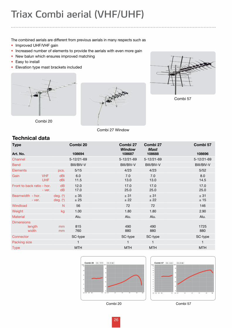
Combi 27 Window
The combined aerials are different from previous aerials in many respects such as• Improved UHF/VHF gain• Increased number of elements to provide the aerials with even more gain• New balun which ensures improved matching• Easy to install• Elevation type mast brackets included
Triax Combi aerial (VHF/UHF)
Combi 20
Combi 57
Technical dataType
Art. No.
Combi 20
108694
Combi 27 Window108687
Combi 27 Mast
108688
Combi 57
108696
Channel 5-12/21-69 5-12/21-69 5-12/21-69 5-12/21-69
Band BIII/BIV-V BIII/BIV-V BIII/BIV-V BIII/BIV-V
Elements pcs. 5/15 4/23 4/23 5/52
Gain VHF UHF
dBidBi
6.011.5
7.013.0
7.013.0
8.014.5
Front to back ratio - hor. - ver.
dBdB
12.017.0
17.025.0
17.025.0
17.025.0
Beamwidth - hor. - ver.
deg. (o)deg. (o)
± 35± 25
± 31± 22
± 31± 22
± 31± 15
Windload N 56 72 72 146
Weight kg 1.00 1.80 1.80 2.90
Material Alu. Alu. Alu. Alu.
Dimensions length width
mmmm
815760
490880
490880
1725880
Connector SC-type SC-type SC-type SC-type
Packing size 1 1 1 1
Type MTH MTH MTH MTH
Combi 57Combi 20
27
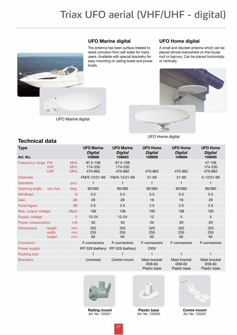
Triax UFO aerial (VHF/UHF - digital)
Technical data
UFO Marine digital
UFO Home digital
Railing mountArt. No. 133221
Centre mountArt. No. 133225
Type
Art. No.
UFO Marine Digital109680
UFO Marine Digital109683
UFO HomeDigital109690
UFO HomeDigital109694
UFO HomeDigital109695
Frequency range FM VHF UHF
MHzMHzMHz
87.5-108174-230470-862
87.5-108174-230470-862 470-862 470-862
47-108174-230470-862
Channels FM/5-12/21-69 FM/5-12/21-69 21-69 21-69 5-12/21-69
Elements pcs. 1 1 1 1 1
Opening angle ver./hor. deg. 90/360 90/360 90/360 90/360 90/360
Windload N 5.5 5.5 5.5 5.5 5.5
Gain dB 28 28 16 16 28
Noise figure dB 2.5 2.5 2.5 2.5 2.5
Max. output voltage dBµV 108 108 100 108 100
Supply voltage V 12-24 12-24 12 5 5
Power consumption mA 50 50 20 20 20
Dimensions length width height
mmmmmm
32525565
32525565
32525565
32525565
32525565
Connector F-connectors F-connectors F-connectors F-connectors F-connectors
Power supply IFP 529 (battery) IFP 529 (battery) 230V
Packing size 1 1 1 1 1
Bracketry Universal Centre mount Mast bracket Ø38-60
Plastic base
Mast bracket Ø38-60
Plastic base
Mast bracket Ø38-60
Plastic base
UFO Marine digitalThe antenna has been surface-treated to resist corrosion from salt water for many years. Available with special bracketry for easy mounting on sailing boats and power boats.
UFO Home digitalA small and discreet antenna which can be placed almost everywhere on the house, roof or balcony. Can be placed horizontally or vertically.
Plastic baseArt. No. 133220
28
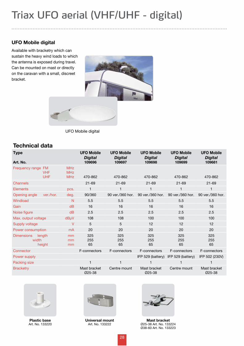
Mast bracketØ25-38 Art. No. 133224Ø38-60 Art. No. 133223
Plastic baseArt. No. 133220
Universal mountArt. No. 133222
Technical dataType
Art. No.
UFO Mobile Digital109696
UFO Mobile Digital109697
UFO Mobile Digital109698
UFO Mobile Digital109699
UFO Mobile Digital109681
Frequency range FM VHF UHF
MHzMHzMHz 470-862 470-862 470-862 470-862 470-862
Channels 21-69 21-69 21-69 21-69 21-69
Elements pcs. 1 1 1 1 1
Opening angle ver./hor. deg. 90/360 90 ver./360 hor. 90 ver./360 hor. 90 ver./360 hor. 90 ver./360 hor.
Windload N 5.5 5.5 5.5 5.5 5.5
Gain dB 16 16 16 16 16
Noise figure dB 2.5 2.5 2.5 2.5 2.5
Max. output voltage dBµV 108 108 100 100 100
Supply voltage V 5 5 12 12 12
Power consumption mA 20 20 20 20 20
Dimensions length width height
mmmmmm
32525565
32525565
32525565
32525565
32525565
Connector F-connectors F-connectors F-connectors F-connectors F-connectors
Power supply IFP 529 (battery) IFP 529 (battery) IFP 502 (230V)
Packing size 1 1 1 1 1
Bracketry Mast bracket Ø25-38
Centre mount Mast bracket Ø25-38
Centre mount Mast bracket Ø25-38
Triax UFO aerial (VHF/UHF - digital)
UFO Mobile digital
Available with bracketry which can sustain the heavy wind loads to which the antenna is exposed during travel. Can be mounted on mast or directly on the caravan with a small, discreet bracket.
UFO Mobile digital
29
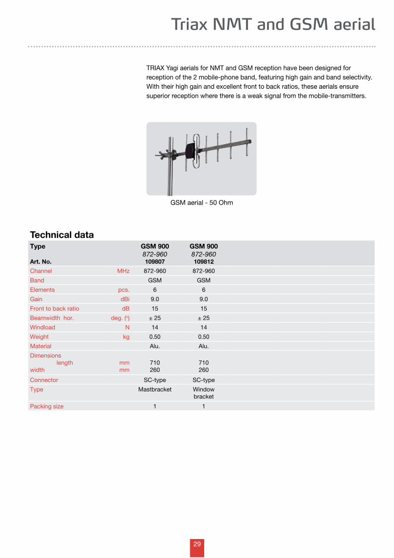
Triax NMT and GSM aerial
Type
Art. No.
GSM 900 872-960109807
GSM 900 872-960109812
Channel MHz 872-960 872-960
Band GSM GSM
Elements pcs. 6 6
Gain dBi 9.0 9.0
Front to back ratio dB 15 15
Beamwidth hor. deg. (o) ± 25 ± 25
Windload N 14 14
Weight kg 0.50 0.50
Material Alu. Alu.
Dimensions length width
mmmm
710260
710260
Connector SC-type SC-type
Type Mastbracket Windowbracket
Packing size 1 1
Technical data
TRIAX Yagi aerials for NMT and GSM reception have been designed for reception of the 2 mobile-phone band, featuring high gain and band selectivity. With their high gain and excellent front to back ratios, these aerials ensure superior reception where there is a weak signal from the mobile-transmitters.
GSM aerial - 50 Ohm
30
Technical data
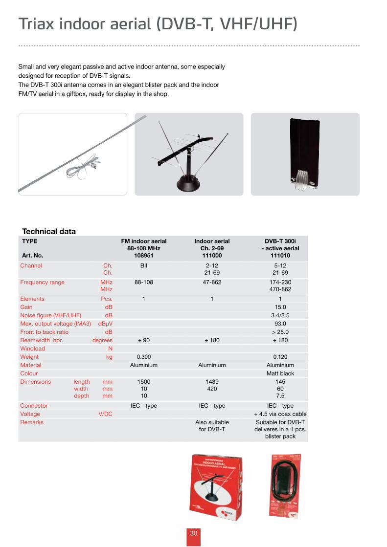
Triax indoor aerial (DVB-T, VHF/UHF)
TYPE
Art. No.
FM indoor aerial88-108 MHz
108951
Indoor aerialCh. 2-69111000
DVB-T 300i- active aerial
111010
Channel Ch.Ch.
BII 2-1221-69
5-1221-69
Frequency range MHzMHz
88-108 47-862 174-230470-862
Elements Pcs. 1 1 1Gain dB 15.0Noise figure (VHF/UHF) dB 3.4/3.5Max. output voltage (IMA3) dBµV 93.0Front to back ratio dB > 25.0Beamwidth hor. degrees ± 90 ± 180 ± 180Windload NWeight kg 0.300 0.120Material Aluminium Aluminium AluminiumColour Matt blackDimensions length width depth
mmmmmm
15001010
1439420
145607.5
Connector IEC - type IEC - type IEC - typeVoltage V/DC + 4.5 via coax cableRemarks Also suitable
for DVB-TSuitable for DVB-Tdeliveres in a 1 pcs.
blister pack
Small and very elegant passive and active indoor antenna, some especially designed for reception of DVB-T signals.The DVB-T 300i antenna comes in an elegant blister pack and the indoor FM/TV aerial in a giftbox, ready for display in the shop.
31
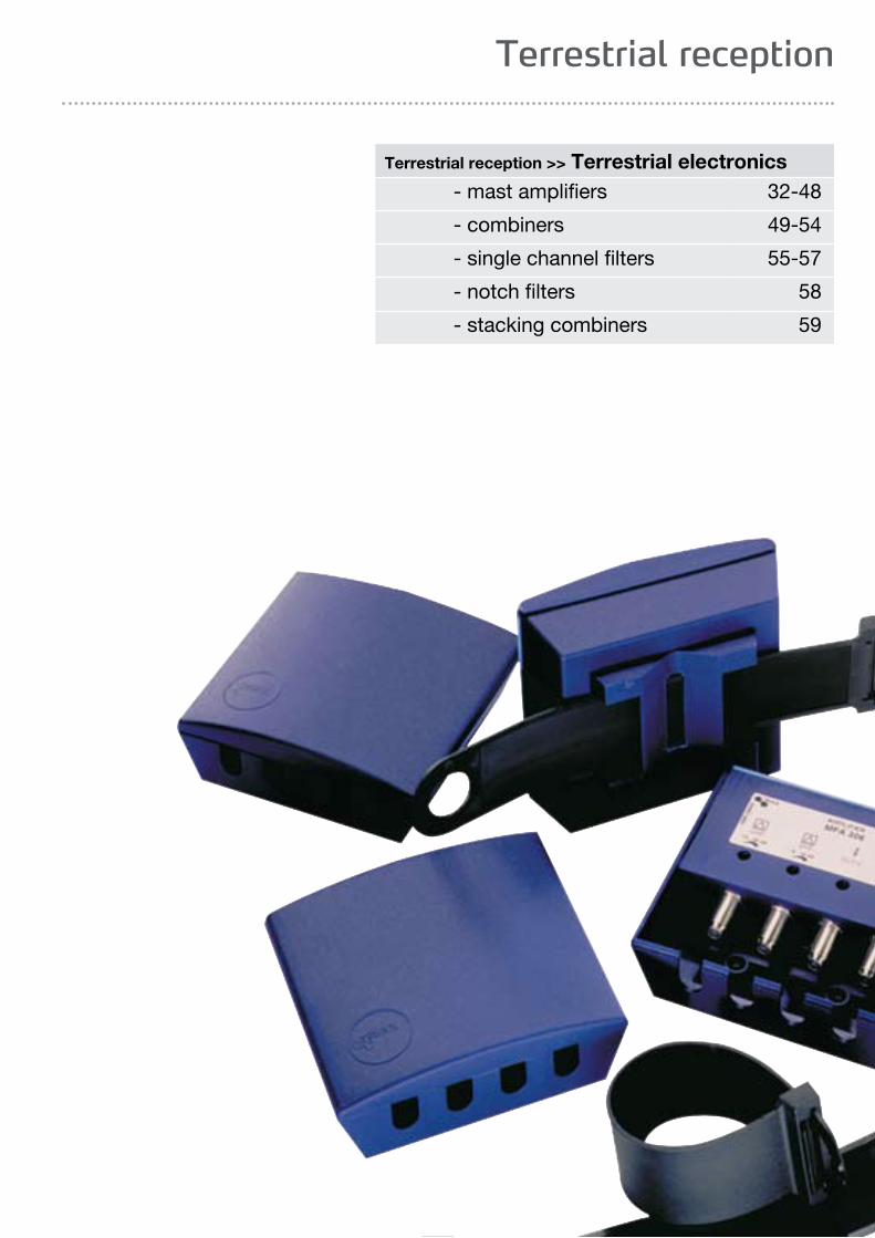
Terrestrial reception
Terrestrial reception >> Terrestrial electronics - mast amplifiers 32-48
- combiners 49-54
- single channel filters 55-57
- notch filters 58
- stacking combiners 59
32
Type
Art. No.
MFA 302
340302
MFA 304
340304
MFA 307
340307
MFA 308
340308
MFA 309
340309
MFA 310
340310
Input 1 Channel Gain
BanddB
UHF+BIII20
UHF20-30
UHF23-33
UHF 222-28
UHF12-22
UHF12-22
Input 2 Channel Gain
BanddB
VHF12-22
BIII13-24
UHF 112-22
BIII12-22
VHF12-22
Input 3 Channel Gain
BanddB
VHF10-20
BI+FM2-12
Noise figure UHF VHF
dBdB
3.03.0
3.05.0
2.53.0
IN1/IN25.0/14.0
3.04.04.0
4.04.0
Max. output voltage@ -60 dB IMA dBµV 103 103 105 110 105 103
Numbers of in-/output 1/1 2/1 2/1 3/1 3/1 2/1
Voltage VDC 12-24 12-24 12-24 12-24 12-24 12-24
Power mA 30 45 45 45 45 45
DC throughpower UHF UHF
Connector F-con F-con F-con F-con F-con F-con
Weight kg 0.230 0.230 0.230 0.230 0.230 0.230
Dimensions Height Depth Width
mmmmmm
10850120
10850
120
10850
120
10850
120
10850
120
10850
120
Remarks
Technical data on MFA mast amplifiers with F-connectors
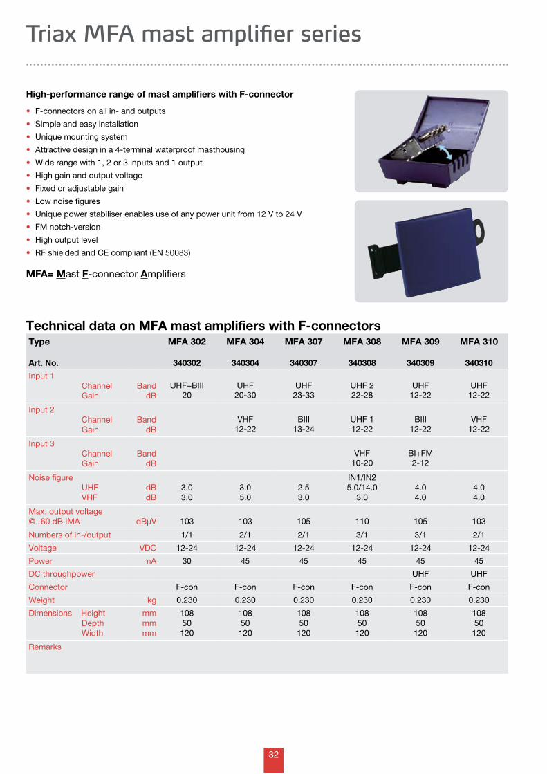
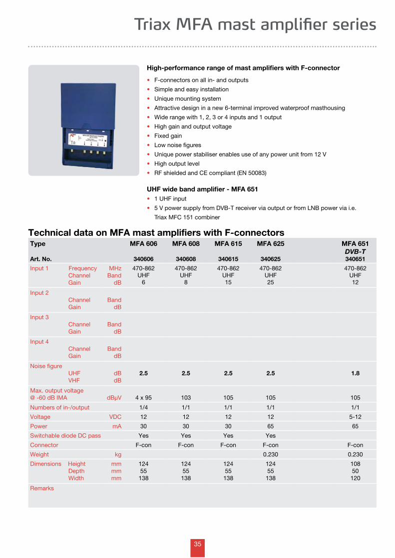
High-performance range of mast amplifiers with F-connector
• F-connectors on all in- and outputs
• Simple and easy installation
• Unique mounting system
• Attractive design in a 4-terminal waterproof masthousing
• Wide range with 1, 2 or 3 inputs and 1 output
• High gain and output voltage
• Fixed or adjustable gain
• Low noise figures
• Unique power stabiliser enables use of any power unit from 12 V to 24 V
• FM notch-version
• High output level
• RF shielded and CE compliant (EN 50083)
MFA= Mast F-connector Amplifiers
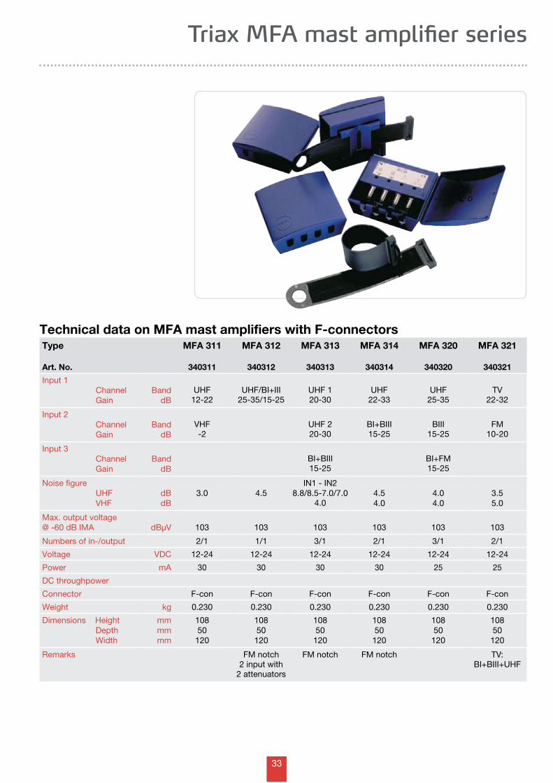
Triax MFA mast amplifier series
33
Technical data on MFA mast amplifiers with F-connectors
Triax MFA mast amplifier series
Type
Art. No.
MFA 311
340311
MFA 312
340312
MFA 313
340313
MFA 314
340314
MFA 320
340320
MFA 321
340321
Input 1 Channel Gain
BanddB
UHF12-22
UHF/BI+III25-35/15-25
UHF 120-30
UHF22-33
UHF25-35
TV22-32
Input 2 Channel Gain
BanddB
VHF-2
UHF 220-30
BI+BIII15-25
BIII15-25
FM10-20
Input 3 Channel Gain
BanddB
BI+BIII15-25
BI+FM15-25
Noise figure UHF VHF
dBdB
3.0 4.5IN1 - IN2
8.8/8.5-7.0/7.04.0
4.54.0
4.04.0
3.55.0
Max. output voltage@ -60 dB IMA dBµV 103 103 103 103 103 103
Numbers of in-/output 2/1 1/1 3/1 2/1 3/1 2/1
Voltage VDC 12-24 12-24 12-24 12-24 12-24 12-24
Power mA 30 30 30 30 25 25
DC throughpower
Connector F-con F-con F-con F-con F-con F-con
Weight kg 0.230 0.230 0.230 0.230 0.230 0.230
Dimensions Height Depth Width
mmmmmm
10850120
10850
120
10850
120
10850
120
10850
120
10850
120
Remarks FM notch2 input with
2 attenuators
FM notch FM notch TV:BI+BIII+UHF
34
Type
Art. No.
MFA 322
340322
MFA 323
340323
MFA 324
340324
MFA 325
340325
MFA 327
340327
MFA 331
340331
Input 1 Channel Gain
BanddB
UHF15
UHF12
UHF25
UHF/VHF25
Ch. 36-69UHF25
BI12-22
Input 2 Channel Gain
BanddB
FM12-22
Input 3 Channel Gain
BanddB
BIII12-22
Input 4 Channel Gain
BanddB
UHF12-22
Noise figure UHF VHF
dBdB
1.8 1.8 1.8 2.22.2
1.8 3.54.0
Max. output voltage@ -60 dB IMA dBµV 4 x 85 105 105 105 105 105
Numbers of in-/output 1/4 1/1 1/1 1/1 1/1 4/1
Voltage VDC 12-24 12-24 12-24 12-24 12-24 12-24
Power mA 30 30 30 25 40 25
DC throughpower
Connector F-con F-con F-con F-con F-con F-con
Weight kg 0.230 0.230 0.230 0.230 0.230 0.230
Dimensions Height Depth Width
mmmmmm
10850120
10850
120
10850
120
10850
120
10850
120
10850
120
Remarks Low noise Low noise Low noise Low noise Low noise
Technical data on MFA mast amplifiers with F-connectors
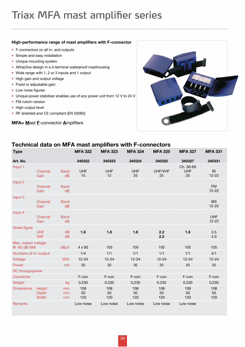
High-performance range of mast amplifiers with F-connector
• F-connectors on all in- and outputs
• Simple and easy installation
• Unique mounting system
• Attractive design in a 4-terminal waterproof masthousing
• Wide range with 1, 2 or 3 inputs and 1 output
• High gain and output voltage
• Fixed or adjustable gain
• Low noise figures
• Unique power stabiliser enables use of any power unit from 12 V to 24 V
• FM notch-version
• High output level
• RF shielded and CE compliant (EN 50083)
MFA= Mast F-connector Amplifiers
Triax MFA mast amplifier series
35
Type
Art. No.
MFA 606
340606
MFA 608
340608
MFA 615
340615
MFA 625
340625
MFA 651 DVB-T340651
Input 1 Frequency Channel Gain
MHzBand
dB
470-862UHF
6
470-862UHF
8
470-862UHF15
470-862UHF25
470-862UHF12
Input 2 Channel Gain
BanddB
Input 3 Channel Gain
BanddB
Input 4 Channel Gain
BanddB
Noise figure UHF VHF
dBdB
2.5 2.5 2.5 2.5 1.8
Max. output voltage@ -60 dB IMA dBµV 4 x 95 103 105 105 105
Numbers of in-/output 1/4 1/1 1/1 1/1 1/1
Voltage VDC 12 12 12 12 5-12
Power mA 30 30 30 65 65
Switchable diode DC pass Yes Yes Yes Yes
Connector F-con F-con F-con F-con F-con
Weight kg 0.230 0.230
Dimensions Height Depth Width
mmmmmm
12455138
12455
138
12455
138
12455
138
10850
120
Remarks
Technical data on MFA mast amplifiers with F-connectors
High-performance range of mast amplifiers with F-connector
• F-connectors on all in- and outputs
• Simple and easy installation
• Unique mounting system
• Attractive design in a new 6-terminal improved waterproof masthousing
• Wide range with 1, 2, 3 or 4 inputs and 1 output
• High gain and output voltage
• Fixed gain
• Low noise figures
• Unique power stabiliser enables use of any power unit from 12 V
• High output level
• RF shielded and CE compliant (EN 50083)
UHF wide band amplifier - MFA 651• 1 UHF input
• 5 V power supply from DVB-T receiver via output or from LNB power via i.e.
Triax MFC 151 combiner
Triax MFA mast amplifier series
36
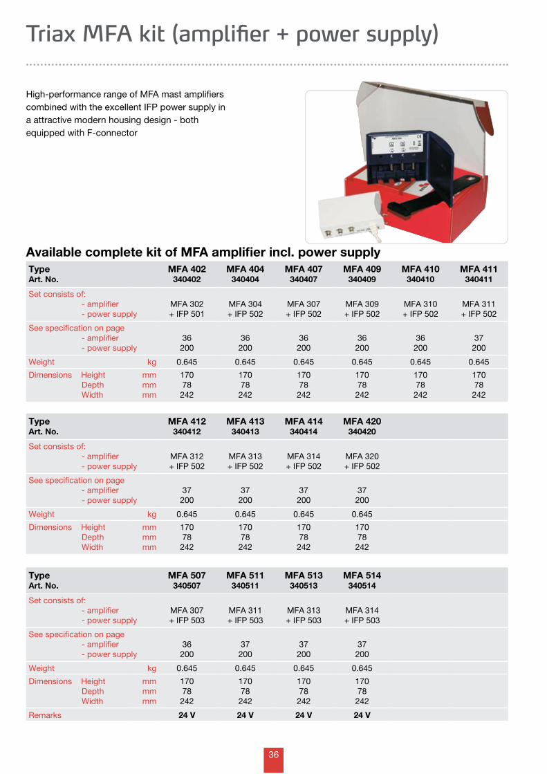
High-performance range of MFA mast amplifiers combined with the excellent IFP power supply ina attractive modern housing design - both equipped with F-connector
Available complete kit of MFA amplifier incl. power supply
Triax MFA kit (amplifier + power supply)
Type Art. No.
MFA 412 340412
MFA 413 340413
MFA 414 340414
MFA 420 340420
Set consists of: - amplifier - power supply
MFA 312+ IFP 502
MFA 313+ IFP 502
MFA 314+ IFP 502
MFA 320+ IFP 502
See specification on page - amplifier - power supply
37200
37200
37200
37200
Weight kg 0.645 0.645 0.645 0.645
Dimensions Height Depth Width
mmmmmm
17078242
17078
242
17078
242
17078
242
Type Art. No.
MFA 402 340402
MFA 404 340404
MFA 407 340407
MFA 409 340409
MFA 410 340410
MFA 411 340411
Set consists of: - amplifier - power supply
MFA 302+ IFP 501
MFA 304+ IFP 502
MFA 307+ IFP 502
MFA 309+ IFP 502
MFA 310+ IFP 502
MFA 311+ IFP 502
See specification on page - amplifier - power supply
36200
36200
36200
36200
36200
37200
Weight kg 0.645 0.645 0.645 0.645 0.645 0.645
Dimensions Height Depth Width
mmmmmm
17078242
17078
242
17078
242
17078
242
17078
242
17078
242
Type Art. No.
MFA 507 340507
MFA 511 340511
MFA 513 340513
MFA 514 340514
Set consists of: - amplifier - power supply
MFA 307+ IFP 503
MFA 311+ IFP 503
MFA 313+ IFP 503
MFA 314+ IFP 503
See specification on page - amplifier - power supply
36200
37200
37200
37200
Weight kg 0.645 0.645 0.645 0.645
Dimensions Height Depth Width
mmmmmm
17078242
17078
242
17078
242
17078
242
Remarks 24 V 24 V 24 V 24 V
37
Technical data on TA mast amplifiers with saddle and clamp-connectors
Triax TA mast amplifier series
Type
Art. No.
TA 4013-322R330487
TA 4013-30R
330502
TA 4213-3R
330521
TA 4312-3R
330541
TA 4312-2R
330542
Input 1 Band Gain dB
UHF20-30
UHF24-34
UHF22-32
UHF22-32
UHF13-23
Input 2 Band Gain dB
VHF10-20
VHF- 1
FM0-10
BIII14-24
BIII13-23
Input 3 Band Gain dB
BI+BIII14-24
BI+FM14-24
BI+FM13-23
Noise figure UHF VHF
dBdB
2.52.5
1.8 2.52.5
2.52.5
3.53.5
Max. output voltage@ -60 dB IMA dBµV 105 105 105 105 105
Numbers of in-/output 2/1 2/1 3/1 3/1 3/1
Voltage VDC 12-24 12-24 12-24 12-24 12-24
Power mA 40 40 40 40 30
DC throughpower No Switchable Switchable Switchable Switchable
Connector S&C S&C S&C S&C S&C
Weight kg 0.230 0.230 0.230 0.230 0.230
Dimensions Height Depth Width
mmmmmm
10850120
10850
120
10850
120
10850
120
10850
120
Remarks
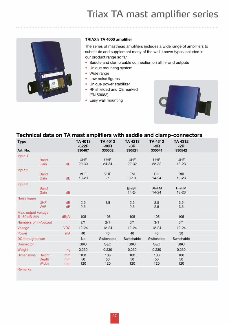
TRIAX’s TA 4000 amplifier
The series of masthead amplifiers includes a wide range of amplifiers to substitute and supplement many of the well-known types included in our product range so far.• Saddle and clamp cable connection on all in- and outputs• Unique mounting system• Wide range• Low noise figures• Unique power stabilizer• RF shielded and CE marked (EN 50083)• Easy wall mounting
38
Technical data on TA mast amplifiers with saddle and clamp-connectors
Triax TA mast amplifier series
Type
Art. No.
TA 13W
333400
TA 13Aband A333430
TA 13Bband B333433
TA 13C/Dband C/D333436
TA 13Eband E333439
TA 13W-1W
333500
Input 1 Channel Gain Noise figure
BanddBdB
21-6913
< 1.9
21-3413
< 1.9
39-5313
< 1.9
48-6913
< 1.9
35-6913
< 1.9
21-6913
< 1.9
Input 2 Channel Gain Noise figure
BanddBdB
BI/BII/BIII- 1.0
Max. output voltage@ -60 dB IMA dBµV 105 105 105 105 105 105
Numbers of in-/output 1/1 1/1 1/1 1/1 1/1 2/1
Voltage VDC 12-24 12-24 12-24 12-24 12-24 12-24
Power mA 15 15 15 15 15 15
DC throughpower No No No No No Switchable
Connector S&C S&C S&C S&C S&C S&C
Weight kg 0.175 0.175 0.175 0.175 0.175 0.175
Dimensions Height Depth Width
mmmmmm
7962118
7962
118
7962
118
7962
118
7962
118
7962
118
Remarks Wideband Groupband Groupband Groupband Groupband Multiband
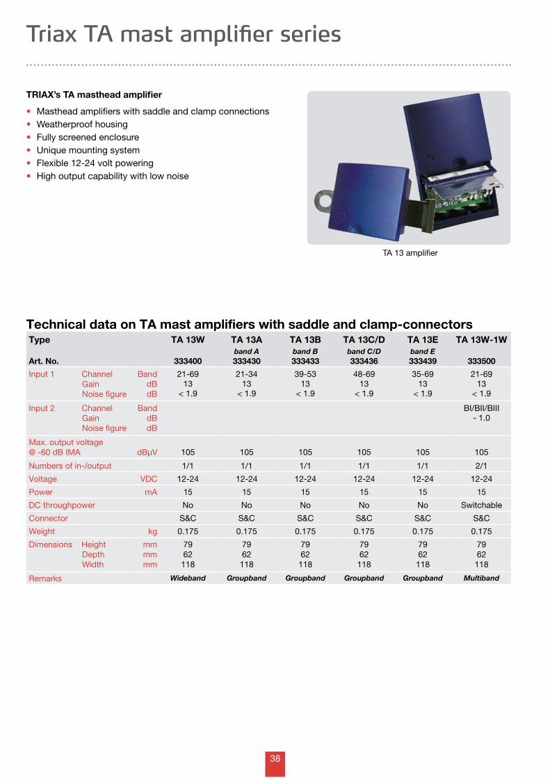
TRIAX’s TA masthead amplifier
• Masthead amplifiers with saddle and clamp connections• Weatherproof housing• Fully screened enclosure• Unique mounting system• Flexible 12-24 volt powering• High output capability with low noise
TA 13 amplifier
39
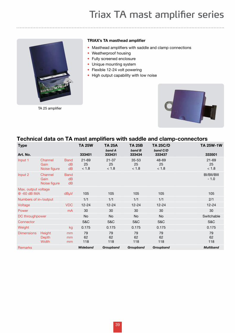
Technical data on TA mast amplifiers with saddle and clamp-connectors
TA 25 amplifier
Triax TA mast amplifier series
TRIAX’s TA masthead amplifier
• Masthead amplifiers with saddle and clamp connections• Weatherproof housing• Fully screened enclosure• Unique mounting system• Flexible 12-24 volt powering• High output capability with low noise
Type
Art. No.
TA 25W
333401
TA 25Aband A333431
TA 25Bband B333434
TA 25C/Dband C/D333437
TA 25W-1W
333501
Input 1 Channel Gain Noise figure
BanddBdB
21-6925
< 1.8
21-3725
< 1.8
35-5325
< 1.8
48-6925
< 1.8
21-6925
< 1.8
Input 2 Channel Gain Noise figure
BanddBdB
BI/BII/BIII- 1.0
Max. output voltage@ -60 dB IMA dBµV 105 105 105 105 105
Numbers of in-/output 1/1 1/1 1/1 1/1 2/1
Voltage VDC 12-24 12-24 12-24 12-24 12-24
Power mA 30 30 30 30 30
DC throughpower No No No No Switchable
Connector S&C S&C S&C S&C S&C
Weight kg 0.175 0.175 0.175 0.175 0.175
Dimensions Height Depth Width
mmmmmm
7962118
7962
118
7962
118
7962
118
7962
118
Remarks Wideband Groupband Groupband Groupband Multiband
40
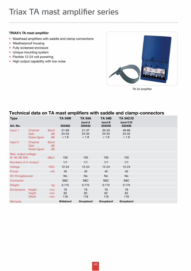
TA 34 amplifier
Technical data on TA mast amplifiers with saddle and clamp-connectors
Triax TA mast amplifier series
TRIAX’s TA mast amplifier
• Masthead amplifiers with saddle and clamp connections• Weatherproof housing• Fully screened enclosure• Unique mounting system• Flexible 12-24 volt powering• High output capability with low noise
Type
Art. No.
TA 34W
333402
TA 34Aband A333432
TA 34Bband B333435
TA 34C/Dband C/D333438
Input 1 Channel Gain Noise figure
BanddBdB
21-6924-34< 1.8
21-3724-34< 1.8
35-5324-34< 1.8
48-6924-34< 1.8
Input 2 Channel Gain Noise figure
BanddBdB
Max. output voltage@ -60 dB IMA dBµV 105 105 105 105
Numbers of in-/output 1/1 1/1 1/1 1/1
Voltage VDC 12-24 12-24 12-24 12-24
Power mA 40 40 40 40
DC throughpower No No No No
Connector S&C S&C S&C S&C
Weight kg 0.175 0.175 0.175 0.175
Dimensions Height Depth Width
mmmmmm
7962118
7962
118
7962
118
7962
118
Remarks Wideband Groupband Groupband Groupband
41
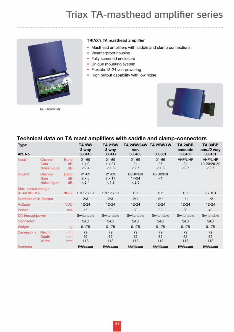
Technical data on TA mast amplifiers with saddle and clamp-connectors
TA - amplifier
Triax TA-masthead amplifier series
TRIAX’s TA masthead amplifier
• Masthead amplifiers with saddle and clamp connections• Weatherproof housing• Fully screened enclosure• Unique mounting system• Flexible 12-24 volt powering• High output capability with low noise
Type
Art. No.
TA 9W/3 way333416
TA 21W/3 way333417
TA 24W/24Wvar.
333466
TA 25W/1W
333501
TA 24BBcascade
333450
TA 30BBcas./2 way
333451
Input 1 Channel Gain Noise figure
BanddBdB
21-691 x 9< 2.4
21-691 x 21< 1.8
21-6924
< 2.5
21-6925
< 1.8
VHF/UHF24
< 2.5
VHF/UHF10-20/20-30
< 2.5
Input 2 Channel Gain Noise figure
BanddBdB
21-692 x 5< 2.4
21-692 x 17< 1.8
BI/BII/BIII14-24< 2.5
BI/BII/BIII- 1
Max. output voltage@ -60 dB IMA dBµV 101/ 2 x 97 101/ 2 x 97 105 105 105 2 x 101
Numbers of in-/output 2/3 2/3 2/1 2/1 1/1 1/2
Voltage VDC 12-24 12-24 12-24 12-24 12-24 12-24
Power mA 15 30 30 30 30 40
DC throughpower Switchable Switchable Switchable Switchable Switchable Switchable
Connector S&C S&C S&C S&C S&C S&C
Weight kg 0.175 0.175 0.175 0.175 0.175 0.175
Dimensions Height Depth Width
mmmmmm
7962118
7962
118
7962
118
7962
118
7962
118
7962
118
Remarks Wideband Wideband Multiband Multiband Wideband Wideband
42
OUT
AMPLIFIER VERSION:
TRIAX
TA 63-3R
OUT
CH 33+43+50
DC
BI + BII
DC
BIII
DC
Rest UHF
DC
CH 23+60
DC
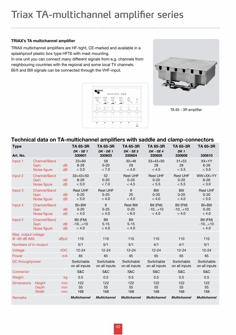
Type
Art. No.
TA 65-3RDK - SE 1330601
TA 65-3RDK - DE 1330603
TA 65-3RDK - SE 3330604
TA 65-3RDK - SE 4330605
TA 65-3RDK 1
330606
TA 65-3R
330610
Input 1 Channel/Band Gain Noise figure
dBdB
23+608-28< 3.0
580-20< 7.0
30+4628
< 4.0
33+43+5028
< 4.5
31+5328
< 3.5
XX+YY6-26< 3.0
Input 2 Channel/Band Gain Noise figure
dBdB
33+43+508-28< 3.0
520-20< 7.0
Rest UHF0-20< 4.5
Rest UHF0-20< 5.5
Rest UHF0-20< 5.5
WW+XX+YY6-26< 3.0
Input 3 Channel/Band Gain Noise figure
dBdB
Rest UHF0-20< 5.0
Rest UHF5-25< 4.0
925
< 4.0
BIII0-20< 4.0
BIII0-20< 4.0
Rest UHF0-20< 5.0
Input 4 Channel/Band Gain Noise figure
dBdB
BI+BIII0-20< 4.0
65-25< 4.0
Rest BIII0-20< 6.5
BII (FM)-10...+10
< 4.0
BII (FM)-10...+10
< 4.0
BI+BIII0-20< 4.0
Input 5 Channel/Band Gain Noise figure
dBdB
BII (FM)-10...+10
< 4.0
BII5-15< 4.0
BII5-15< 4.0
BII (FM)-10...+10
< 4.0
Max. output voltage@ -60 dB IMA dBµV 110 110 110 110 110 110
Numbers of in-/output 5/1 5/1 5/1 4/1 4/1 5/1
Voltage VDC 12-24 12-24 12-24 12-24 12-24 12-24
Power mA 65 65 65 65 65 65
DC throughpower Switchableon all inputs
Switchableon all inputs
Switchableon all inputs
Switchableon all inputs
Switchableon all inputs
Switchableon all inputs
Connector S&C S&C S&C S&C S&C S&C
Weight kg 0.5 0.5 0.5 0.5 0.5 0.5
Dimensions Height Depth Width
mmmmmm
12255168
12255
168
12255
168
12255
168
12255
168
12255
168
Remarks Multichannel Multichannel Multichannel Multichannel Multichannel Multichannel
Technical data on TA-multichannel amplifiers with saddle and clamp-connectors
TA 65 - 3R amplifier
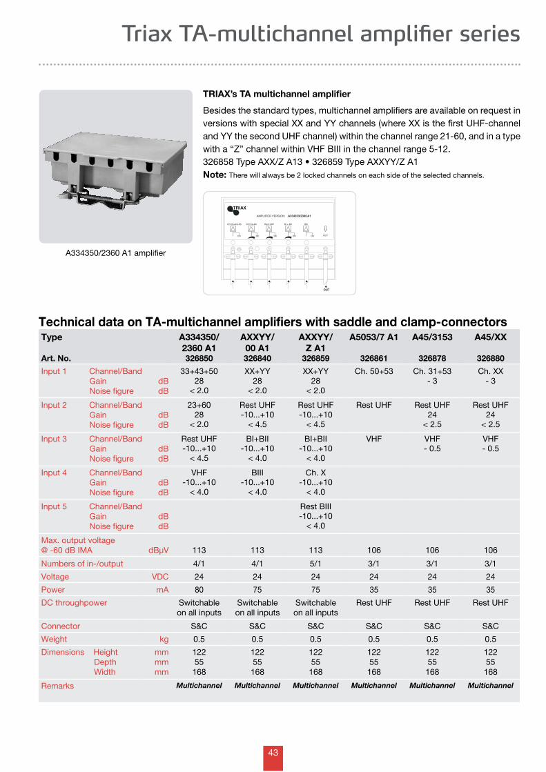
TRIAX’s TA multichannel amplifier
TRIAX multichannel amplifiers are HF-tight, CE-marked and available in a splashproof plastic box type HFT6 with mast mounting.In one unit you can connect many different signals from e.g. channels from neighbouring countries with the regional and some local TV channels.BI/II and BIII signals can be connected through the VHF-input.
Triax TA-multichannel amplifier series
43
OUT
AMPLIFIER VERSION:
TRIAX
A334353/2360 A1
OUT
CH 33+43+50
DC
BI + BII
DC
BIII
DC
Rest UHF
DC
CH 23+60
DC
Technical data on TA-multichannel amplifiers with saddle and clamp-connectors
A334350/2360 A1 amplifier
TRIAX’s TA multichannel amplifier
Besides the standard types, multichannel amplifiers are available on request in versions with special XX and YY channels (where XX is the first UHF-channel and YY the second UHF channel) within the channel range 21-60, and in a type with a “Z” channel within VHF BIII in the channel range 5-12.326858TypeAXX/ZA13•326859TypeAXXYY/ZA1Note: There will always be 2 locked channels on each side of the selected channels.
Type
Art. No.
A334350/2360 A1326850
AXXYY/00 A1326840
AXXYY/Z A1
326859
A5053/7 A1
326861
A45/3153
326878
A45/XX
326880
Input 1 Channel/Band Gain Noise figure
dBdB
33+43+5028
< 2.0
XX+YY28
< 2.0
XX+YY28
< 2.0
Ch. 50+53 Ch. 31+53- 3
Ch. XX- 3
Input 2 Channel/Band Gain Noise figure
dBdB
23+6028
< 2.0
Rest UHF-10...+10
< 4.5
Rest UHF-10...+10
< 4.5
Rest UHF Rest UHF24
< 2.5
Rest UHF24
< 2.5
Input 3 Channel/Band Gain Noise figure
dBdB
Rest UHF-10...+10
< 4.5
BI+BII-10...+10
< 4.0
BI+BII-10...+10
< 4.0
VHF VHF- 0.5
VHF- 0.5
Input 4 Channel/Band Gain Noise figure
dBdB
VHF-10...+10
< 4.0
BIII-10...+10
< 4.0
Ch. X-10...+10
< 4.0
Input 5 Channel/Band Gain Noise figure
dBdB
Rest BIII-10...+10
< 4.0
Max. output voltage@ -60 dB IMA dBµV 113 113 113 106 106 106
Numbers of in-/output 4/1 4/1 5/1 3/1 3/1 3/1
Voltage VDC 24 24 24 24 24 24
Power mA 80 75 75 35 35 35
DC throughpower Switchableon all inputs
Switchableon all inputs
Switchableon all inputs
Rest UHF Rest UHF Rest UHF
Connector S&C S&C S&C S&C S&C S&C
Weight kg 0.5 0.5 0.5 0.5 0.5 0.5
Dimensions Height Depth Width
mmmmmm
12255168
12255
168
12255
168
12255
168
12255
168
12255
168
Remarks Multichannel Multichannel Multichannel Multichannel Multichannel Multichannel
Triax TA-multichannel amplifier series
44
Type
Art. No.
TMA 18W-U
333324
TMA 28W-U
333325
TMA 12/2-U
333326
TMA 24W-2W-U333570
TMA 24W-20W-U333571
Input 1 Channel Gain Noise figure
dBdB
21-6918
< 3.0
21-6928
< 3.0
21-692 x 12< 4.5
21-6925
< 3.0
21-6914-24< 4.0
Input 2 Channel Gain Noise figure
dBdB
BI/BII/BIII- 2.0
BI/BII/BIII10-20< 3.0
Input 3 Channel Gain Noise figure
dBdB
Max. output voltage@ -60 dB IMA dBµV 105 105 2 x 98 105 105
Numbers of in-/output 1/1 1/2 1/2 2/1 2/1
Voltage VDC 12-24 12-24 12-24 12-24 12-24
Power mA 20 30 25 30 30
DC throughpower No No No No/No No/No
Connector S&C S&C S&C S&C S&C
Weight kg 0.125 0.125 0.125 0.125 0.125
Dimensions Height Depth Width
mmmmmm
695594
695594
695594
695594
695594
Remarks Wideband Wideband Wideband Multiband Multiband
Technical data on TMA-mast amplifiers with saddle and clamp-connectors
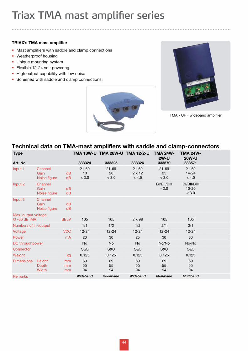
TMA - UHF wideband amplifier
TRIAX’s TMA mast amplifier
• Mast amplifiers with saddle and clamp connections• Weatherproof housing• Unique mounting system• Flexible 12-24 volt powering• High output capability with low noise• Screened with saddle and clamp connections.
Triax TMA mast amplifier series
45
Type - Art. No.SCA 2051-1 333251SCA 2052-1 333252SCA 2053-1 333253SCA 2054-1 333254SCA 2055-1 333255
SCA 2056-1 333256SCA 2057-1 333257SCA 2058-1 333258SCA 2059-1 333259SCA 2060-1 333260
Type - Art. No.SCA 2031-1 333231SCA 2032-1 333232SCA 2033-1 333233SCA 2034-1 333234SCA 2035-1 333235
SCA 2036-1 333236SCA 2037-1 333237SCA 2038-1 333238SCA 2039-1 333239SCA 2040-1 333240
Type - Art. No.SCA 2021-1 333221SCA 2022-1 333222SCA 2023-1 333223SCA 2024-1 333224SCA 2025-1 333225
SCA 2026-1 333226SCA 2027-1 333227SCA 2028-1 333228SCA 2029-1 333229SCA 2030-1 333230
Type - Art. No.SCA 2041-1 333241SCA 2042-1 333242SCA 2043-1 333243SCA 2044-1 333244SCA 2045-1 333245
SCA 2046-1 333246SCA 2047-1 333247SCA 2048-1 333248SCA 2049-1 333249SCA 2050-1 333250
Type - Art. No. SCA 2063-1 333263SCA 2064-1 333264SCA 2065-1 333265SCA 2066-1 333266SCA 2067-1 333267SCA 2068-1 333268SCA 2069-1 333269
SCA 20xx-1 range in 1 channel amplifier
Triax UHF single channel amplifiers
Technical data on SCA single channel amplifier with saddle and clamp-connectorsType
Art. No.
SCA439-443333220
SCA 2021-1
333221
SCA 2032-1
333232
SCA 2045-1
333245
SCA 2056-1
333256
SCA 2069-1
333269
Input 1 Channel Gain Noise figure
dBdB
S38204.0
21204.0
32204.0
45204.0
56204.0
69204.0
Input 2 Channel Gain Noise figure
BanddBdB
Rest VHF/UHF- 1
Rest VHF/UHF- 1
Rest VHF/UHF- 1
Rest VHF/UHF- 1
Rest VHF/UHF- 1
Rest VHF/UHF- 1
Max. output voltage@ -60 dB IMA dBµV 116 116 116 116 116 116
Numbers of in-/output 2/1 2/1 2/1 2/1 2/1 2/1
Voltage VDC 12-24 12-24 12-24 12-24 12-24 12-24
Power mA 30 30 30 30 30 30
DC throughpower Rest VHF/UHF Rest VHF/UHF Rest VHF/UHF Rest VHF/UHF Rest VHF/UHF Rest VHF/UHF
Connector S&C S&C S&C S&C S&C S&C
Weight kg 0.175 0.175 0.175 0.175 0.175 0.175
Dimensions Height Depth Width
mmmmmm
7962118
7962
118
7962
118
7962
118
7962
118
7962
118
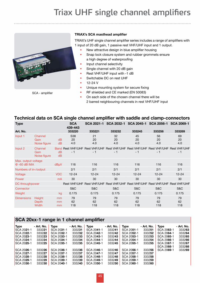
TRIAX’s SCA masthead amplifier
TRIAX’s UHF single channel amplifier series includes a range of amplifiers with 1 input of 20 dB gain, 1 passive rest VHF/UHF input and 1 output.
• New attractive design in blue amplifier housing• Snap lock closure system and rubber grommets ensure a high degree of waterproofing• Input channel selectivity• Single channel with 20 dB gain• Rest VHF/UHF input with -1 dB• Switchable DC on rest UHF• 12-24 V• Unique mounting system for secure fixing• RF shielded and CE marked (EN 50083) • On each side of the chosen channel there will be 2 barred neighbouring channels in rest VHF/UHF input
SCA - amplifier
46
Ant.FM
Ant.BI
TOPower Supply
AMPLIFIER: A88108A1
FM VHFBI
OUT+24V
TRIAX
Ant.VHF - CH.
Ant.VHF
TOPower Supply
AMPLIFIER: Axx A1
CH.xx VHF OUT+24V
TRIAX
Triax FM and VHF single channel amplifiers
Technical data on Axx single channel amplifiers with saddle and clamp-connectorsType
Art. No.
A88108 A1
326976
AXX A1Ch. 5-6326905
AXX A1Ch. 7-8326907
AXX A1Ch. 9-11326909
AXX A1Ch. 12326911
AXXYY A2multichannel
326980
Input 1 Channel Frequency Gain Noise figure
MHzdBdB
FM88-108
15< 3.0
5 or 6 BIII25
< 4.5
7 or 8 BIII25
< 4.5
9 or 11 BIII25
< 4.5
12 BIII25
< 4.5
XXYY
25< 4.5
Input 1 Channel Frequency Gain Noise figure
MHzdBdB
BI
- 1
Rest VHF/UHF
- 1
Rest VHF/UHF
- 1
Rest VHF/UHF
- 1
Rest VHF/UHF
- 1
Rest VHF/UHF
- 1
Max. output voltage@ -60 dB IMA dBµV 112 116 116 116 116 116
Numbers of in-/output 2/1 2/1 2/1 2/1 2/1 2/1
Voltage VDC 24 24 24 24 24 24
Power mA 35 35 35 35 35 35
DC throughpower BI SwitchableVHF/UHF
SwitchableVHF/UHF
SwitchableVHF/UHF
SwitchableVHF/UHF
SwitchableVHF/UHF
Connector S&C S&C S&C S&C S&C S&C
Weight kg 0.250 0.250 0.250 0.250 0.250 0.250
Dimensions Height Depth Width
mmmmmm
9048115
9048
115
9048
115
9048
115
9048
115
9048
115
Remarks
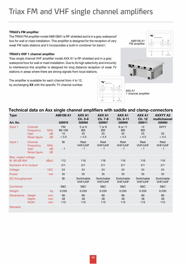
TRIAX’s FM amplifierThe TRIAX FM amplifier model A88108A1 is RF-shielded and is in a grey waterproof box for wall or mast installation. This amplifier is designed for the reception of very weak FM radio stations and it incorporates a built-in combiner for band I.
TRIAX’s VHF 1 channel amplifierTriax single channel VHF amplifier model AXX A1 is RF-shielded and in a grey waterproof box for wall or mast installation. Due to its high selectivity and immunity to interference this amplifier is designed for long distance reception of weak TV stations in areas where there are strong signals from local stations.
The amplifier is available for each channel from 4 to 12, by exchanging XX with the specific TV channel number.
A05 A11 channel amplifier
A88108 A1FM amplifier
47
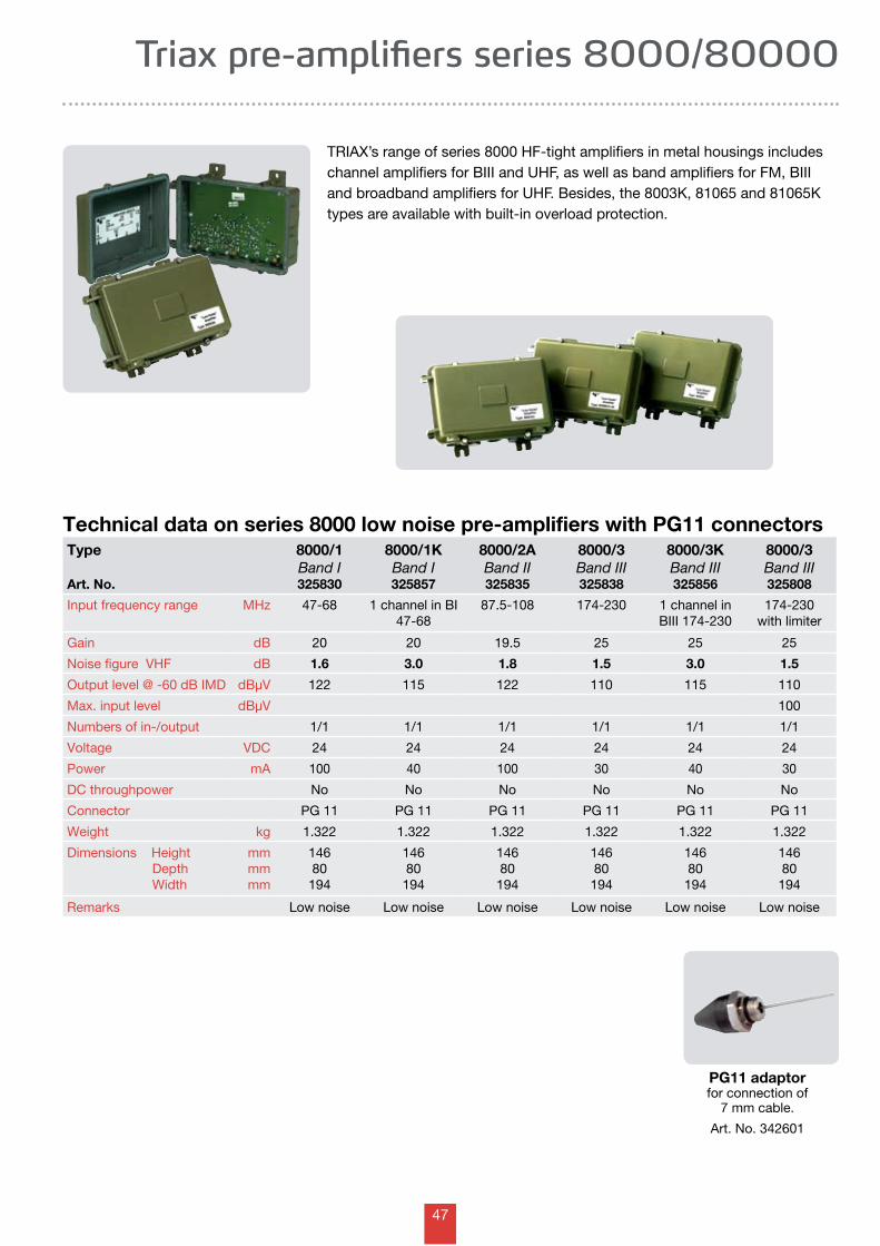
PG11 adaptor for connection of
7 mm cable.
Art. No. 342601
Type
Art. No.
8000/1 Band I325830
8000/1K Band I325857
8000/2A Band II325835
8000/3 Band III325838
8000/3K Band III325856
8000/3 Band III325808
Input frequency range MHz 47-68 1 channel in BI 47-68
87.5-108 174-230 1 channel in BIII 174-230
174-230with limiter
Gain dB 20 20 19.5 25 25 25
Noise figure VHF dB 1.6 3.0 1.8 1.5 3.0 1.5
Output level @ -60 dB IMD dBµV 122 115 122 110 115 110
Max. input level dBµV 100
Numbers of in-/output 1/1 1/1 1/1 1/1 1/1 1/1
Voltage VDC 24 24 24 24 24 24
Power mA 100 40 100 30 40 30
DC throughpower No No No No No No
Connector PG 11 PG 11 PG 11 PG 11 PG 11 PG 11
Weight kg 1.322 1.322 1.322 1.322 1.322 1.322
Dimensions Height Depth Width
mmmmmm
14680194
14680
194
14680
194
14680
194
14680
194
14680
194
Remarks Low noise Low noise Low noise Low noise Low noise Low noise
Technical data on series 8000 low noise pre-amplifiers with PG11 connectors
TRIAX’s range of series 8000 HF-tight amplifiers in metal housings includes channel amplifiers for BIII and UHF, as well as band amplifiers for FM, BIII and broadband amplifiers for UHF. Besides, the 8003K, 81065 and 81065K types are available with built-in overload protection.
Triax pre-amplifiers series 8000/80000
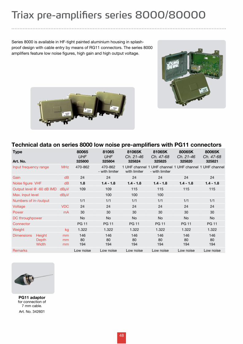
48
Series 8000 is available in HF-tight painted aluminium housing in splash-proof design with cable entry by means of RG11 connectors. The series 8000 amplifiers feature low noise figures, high gain and high output voltage.
Technical data on series 8000 low noise pre-amplifiers with PG11 connectorsType
Art. No.
80065 UHF
325800
81065 UHF
325804
81065K Ch. 21-46
325824
81065K Ch. 47-68
325825
80065K Ch. 21-46
325820
80065K Ch. 47-68
325821
Input frequency range MHz 470-862 470-862- with limiter
1 UHF channelwith limiter
1 UHF channel- with limiter
1 UHF channel 1 UHF channel
Gain dB 24 24 24 24 24 24
Noise figure VHF dB 1.8 1.4 - 1.8 1.4 - 1.8 1.4 - 1.8 1.4 - 1.8 1.4 - 1.8
Output level @ -60 dB IMD dBµV 109 109 115 115 115 115
Max. input level dBµV 100 100 100
Numbers of in-/output 1/1 1/1 1/1 1/1 1/1 1/1
Voltage VDC 24 24 24 24 24 24
Power mA 30 30 30 30 30 30
DC throughpower No No No No No No
Connector PG 11 PG 11 PG 11 PG 11 PG 11 PG 11
Weight kg 1.322 1.322 1.322 1.322 1.322 1.322
Dimensions Height Depth Width
mmmmmm
14680194
14680
194
14680
194
14680
194
14680
194
14680
194
Remarks Low noise Low noise Low noise Low noise Low noise Low noise
Triax pre-amplifiers series 8000/80000
PG11 adaptor for connection of
7 mm cable.
Art. No. 342601
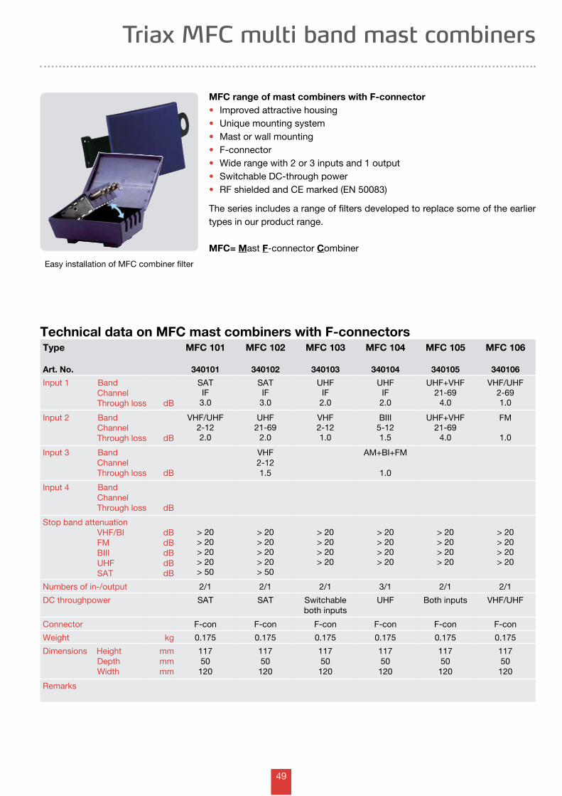
49
Triax MFC multi band mast combiners
MFC range of mast combiners with F-connector• Improved attractive housing • Unique mounting system• Mast or wall mounting• F-connector• Wide range with 2 or 3 inputs and 1 output• Switchable DC-through power• RF shielded and CE marked (EN 50083)
The series includes a range of filters developed to replace some of the earlier types in our product range.
MFC= Mast F-connector Combiner
Technical data on MFC mast combiners with F-connectorsType
Art. No.
MFC 101
340101
MFC 102
340102
MFC 103
340103
MFC 104
340104
MFC 105
340105
MFC 106
340106
Input 1 Band Channel Through loss dB
SATIF
3.0
SATIF
3.0
UHFIF
2.0
UHFIF
2.0
UHF+VHF21-69
4.0
VHF/UHF2-691.0
Input 2 Band Channel Through loss dB
VHF/UHF2-122.0
UHF21-69
2.0
VHF2-121.0
BIII5-121.5
UHF+VHF21-69
4.0
FM
1.0
Input 3 Band Channel Through loss dB
VHF2-121.5
AM+BI+FM
1.0
Input 4 Band Channel Through loss dB
Stop band attenuation VHF/BI FM BIII UHF SAT
dBdBdBdBdB
> 20> 20> 20> 20> 50
> 20> 20> 20> 20> 50
> 20> 20> 20> 20
> 20> 20> 20> 20
> 20> 20> 20> 20
> 20> 20> 20> 20
Numbers of in-/output 2/1 2/1 2/1 3/1 2/1 2/1
DC throughpower SAT SAT Switchableboth inputs
UHF Both inputs VHF/UHF
Connector F-con F-con F-con F-con F-con F-con
Weight kg 0.175 0.175 0.175 0.175 0.175 0.175
Dimensions Height Depth Width
mmmmmm
11750120
11750
120
11750
120
11750
120
11750
120
11750
120
Remarks
Easy installation of MFC combiner filter
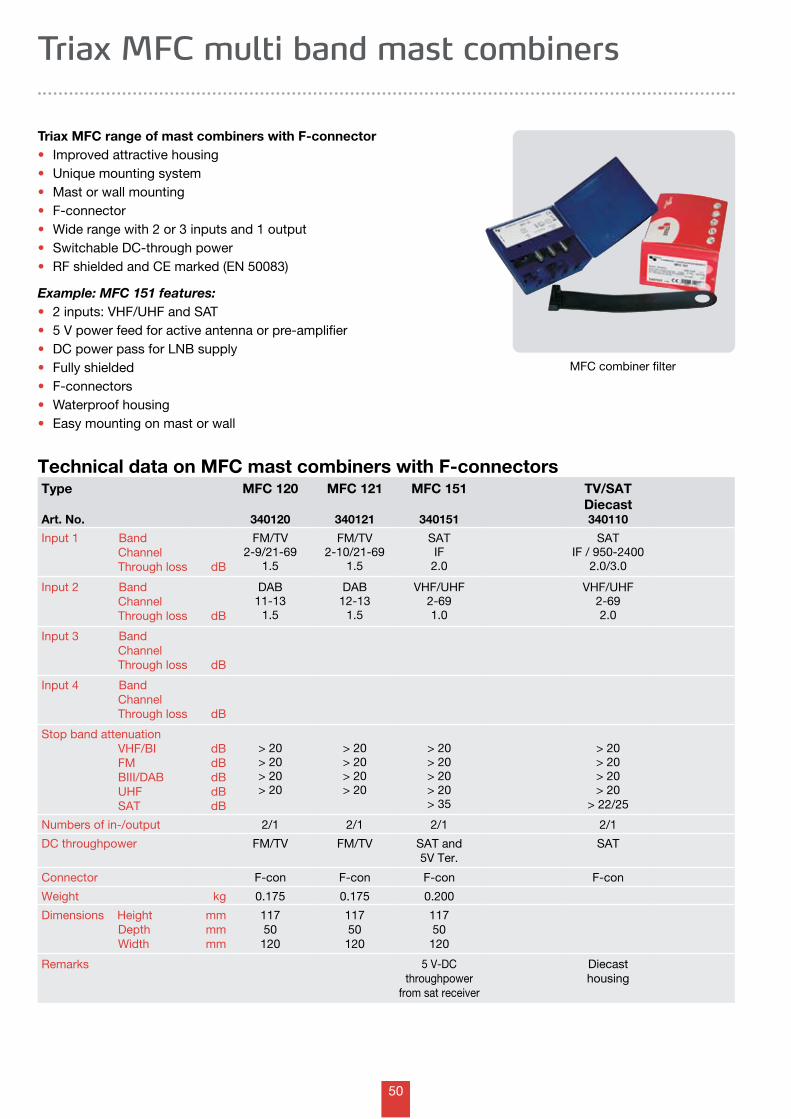
50
Technical data on MFC mast combiners with F-connectors
Triax MFC range of mast combiners with F-connector• Improved attractive housing • Unique mounting system• Mast or wall mounting• F-connector• Wide range with 2 or 3 inputs and 1 output• Switchable DC-through power• RF shielded and CE marked (EN 50083)
Example: MFC 151 features:• 2 inputs: VHF/UHF and SAT• 5 V power feed for active antenna or pre-amplifier • DC power pass for LNB supply• Fully shielded• F-connectors• Waterproof housing• Easy mounting on mast or wall
Triax MFC multi band mast combiners
Type
Art. No.
MFC 120
340120
MFC 121
340121
MFC 151
340151
TV/SAT Diecast340110
Input 1 Band Channel Through loss dB
FM/TV2-9/21-69
1.5
FM/TV2-10/21-69
1.5
SATIF
2.0
SATIF / 950-2400
2.0/3.0
Input 2 Band Channel Through loss dB
DAB11-13
1.5
DAB12-13
1.5
VHF/UHF2-691.0
VHF/UHF2-692.0
Input 3 Band Channel Through loss dB
Input 4 Band Channel Through loss dB
Stop band attenuation VHF/BI FM BIII/DAB UHF SAT
dBdBdBdBdB
> 20> 20> 20> 20
> 20> 20> 20> 20
> 20> 20> 20> 20> 35
> 20> 20> 20> 20
> 22/25
Numbers of in-/output 2/1 2/1 2/1 2/1
DC throughpower FM/TV FM/TV SAT and5V Ter.
SAT
Connector F-con F-con F-con F-con
Weight kg 0.175 0.175 0.200
Dimensions Height Depth Width
mmmmmm
11750120
11750
120
11750
120
Remarks 5 V-DC throughpower
from sat receiver
Diecast housing
MFC combiner filter
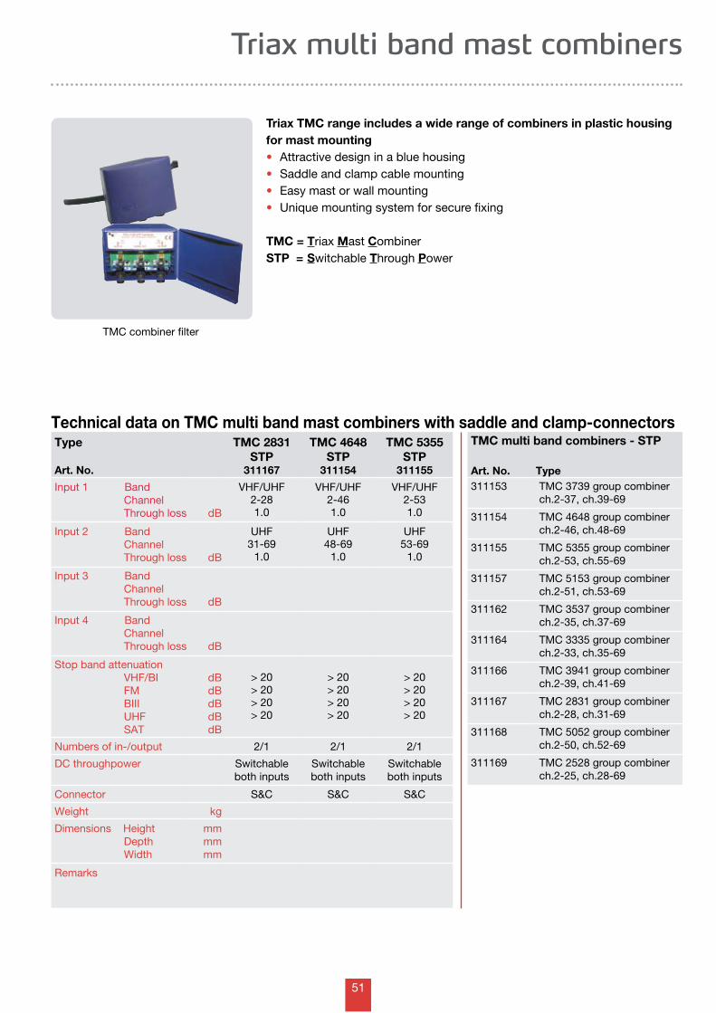
51
Triax multi band mast combiners
Triax TMC range includes a wide range of combiners in plastic housing for mast mounting• Attractive design in a blue housing• Saddle and clamp cable mounting • Easy mast or wall mounting• Unique mounting system for secure fixing
TMC = Triax Mast Combiner STP = Switchable Through Power
Technical data on TMC multi band mast combiners with saddle and clamp-connectorsType
Art. No.
TMC 2831 STP
311167
TMC 4648 STP
311154
TMC 5355 STP
311155
Input 1 Band Channel Through loss dB
VHF/UHF2-281.0
VHF/UHF2-461.0
VHF/UHF2-531.0
Input 2 Band Channel Through loss dB
UHF31-69
1.0
UHF48-69
1.0
UHF53-69
1.0
Input 3 Band Channel Through loss dB
Input 4 Band Channel Through loss dB
Stop band attenuation VHF/BI FM BIII UHF SAT
dBdBdBdBdB
> 20> 20> 20> 20
> 20> 20> 20> 20
> 20> 20> 20> 20
Numbers of in-/output 2/1 2/1 2/1
DC throughpower Switchableboth inputs
Switchableboth inputs
Switchableboth inputs
Connector S&C S&C S&C
Weight kg
Dimensions Height Depth Width
mmmmmm
Remarks
TMC multi band combiners - STP
Art. No. Type311153 TMC 3739 group combiner
ch.2-37, ch.39-69
311154 TMC 4648 group combiner ch.2-46, ch.48-69
311155 TMC 5355 group combiner ch.2-53, ch.55-69
311157 TMC 5153 group combiner ch.2-51, ch.53-69
311162 TMC 3537 group combiner ch.2-35, ch.37-69
311164 TMC 3335 group combiner ch.2-33, ch.35-69
311166 TMC 3941 group combiner ch.2-39, ch.41-69
311167 TMC 2831 group combiner ch.2-28, ch.31-69
311168 TMC 5052 group combiner ch.2-50, ch.52-69
311169 TMC 2528 group combiner ch.2-25, ch.28-69
TMC combiner filter
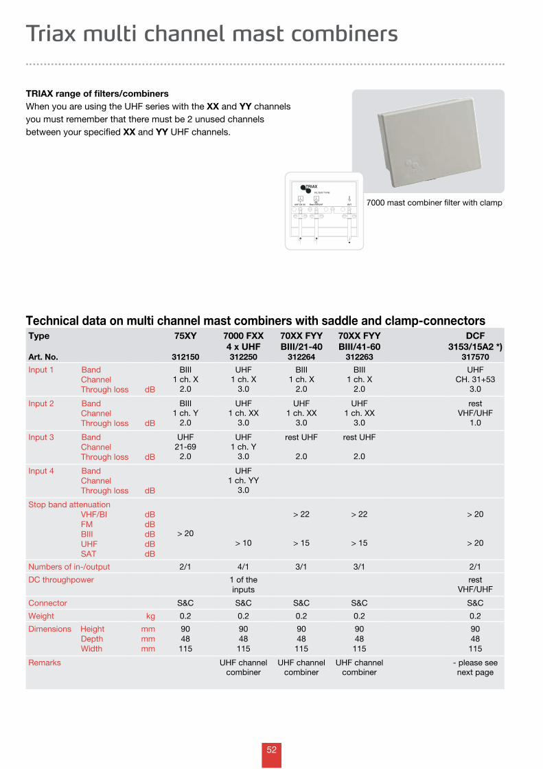
52
OUTDC
Rest VHF/UHFUHF CH XX
FILTER TYPE:
TRIAX
Technical data on multi channel mast combiners with saddle and clamp-connectors
TRIAX range of filters/combinersWhen you are using the UHF series with the XX and YY channels you must remember that there must be 2 unused channels between your specified XX and YY UHF channels.
Triax multi channel mast combiners
Type
Art. No.
75XY
312150
7000 FXX 4 x UHF312250
70XX FYY BIII/21-40
312264
70XX FYY BIII/41-60
312263
DCF 3153/15A2 *)
317570
Input 1 Band Channel Through loss dB
BIII1 ch. X
2.0
UHF1 ch. X
3.0
BIII1 ch. X
2.0
BIII1 ch. X
2.0
UHFCH. 31+53
3.0
Input 2 Band Channel Through loss dB
BIII1 ch. Y
2.0
UHF1 ch. XX
3.0
UHF1 ch. XX
3.0
UHF1 ch. XX
3.0
restVHF/UHF
1.0
Input 3 Band Channel Through loss dB
UHF21-69
2.0
UHF1 ch. Y
3.0
rest UHF
2.0
rest UHF
2.0
Input 4 Band Channel Through loss dB
UHF1 ch. YY
3.0
Stop band attenuation VHF/BI FM BIII UHF SAT
dBdBdBdBdB
> 20> 10
> 22
> 15
> 22
> 15
> 20
> 20
Numbers of in-/output 2/1 4/1 3/1 3/1 2/1
DC throughpower 1 of theinputs
restVHF/UHF
Connector S&C S&C S&C S&C S&C
Weight kg 0.2 0.2 0.2 0.2 0.2
Dimensions Height Depth Width
mmmmmm
9048115
9048
115
9048
115
9048
115
9048
115
Remarks UHF channelcombiner
UHF channelcombiner
UHF channelcombiner
- please see next page
7000 mast combiner filter with clamp
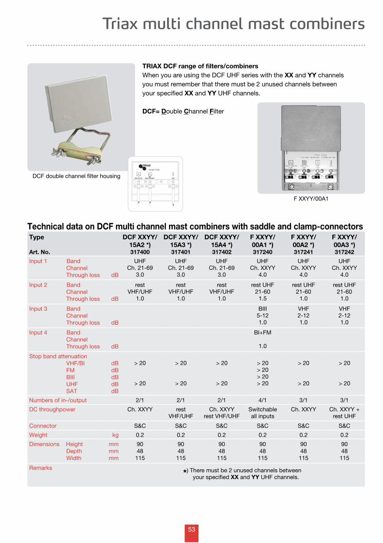
53
OUTDC
Rest VHF/UHFUHF CH XX
FILTER TYPE:
TRIAX
Triax multi channel mast combiners
TRIAX DCF range of filters/combinersWhen you are using the DCF UHF series with the XX and YY channels you must remember that there must be 2 unused channels between your specified XX and YY UHF channels.
DCF= Double Channel Filter
Technical data on DCF multi channel mast combiners with saddle and clamp-connectorsType
Art. No.
DCF XXYY/ 15A2 *)317400
DCF XXYY/ 15A3 *)317401
DCF XXYY/ 15A4 *)317402
F XXYY/ 00A1 *)317240
F XXYY/ 00A2 *)317241
F XXYY/ 00A3 *)317242
Input 1 Band Channel Through loss dB
UHFCh. 21-69
3.0
UHFCh. 21-69
3.0
UHFCh. 21-69
3.0
UHFCh. XXYY
4.0
UHFCh. XXYY
4.0
UHFCh. XXYY
4.0
Input 2 Band Channel Through loss dB
restVHF/UHF
1.0
restVHF/UHF
1.0
restVHF/UHF
1.0
rest UHF21-60
1.5
rest UHF21-60
1.0
rest UHF21-60
1.0
Input 3 Band Channel Through loss dB
BIII5-121.0
VHF2-121.0
VHF2-121.0
Input 4 Band Channel Through loss dB
BI+FM
1.0
Stop band attenuation VHF/BI FM BIII UHF SAT
dBdBdBdBdB
> 20
> 20
> 20
> 20
> 20
> 20
> 20> 20> 20> 20
> 20
> 20
> 20
> 20
Numbers of in-/output 2/1 2/1 2/1 4/1 3/1 3/1
DC throughpower Ch. XXYY restVHF/UHF
Ch. XXYYrest VHF/UHF
Switchable all inputs
Ch. XXYY Ch. XXYY +rest UHF
Connector S&C S&C S&C S&C S&C S&C
Weight kg 0.2 0.2 0.2 0.2 0.2 0.2
Dimensions Height Depth Width
mmmmmm
9048115
9048
115
9048
115
9048
115
9048
115
9048
115
Remarks*) There must be 2 unused channels between
your specified XX and YY UHF channels.
DCF double channel filter housing
F XXYY/00A1
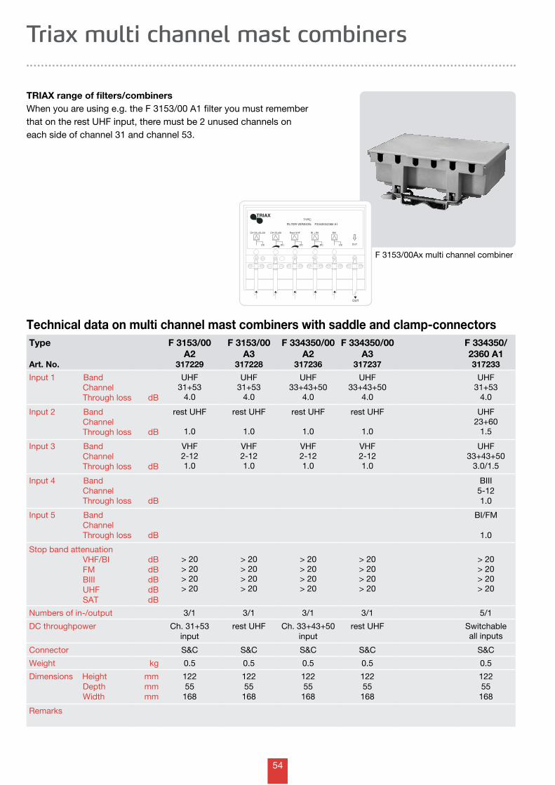
54
OUT
FILTER VERSION:
TRIAX
F334353/2360 A1
OUT
CH 33+43+50
DC
BI + BII
DC
BIII
DC
TYPE:
Rest UHF
DC
CH 23+60
DC
Technical data on multi channel mast combiners with saddle and clamp-connectors
TRIAX range of filters/combinersWhen you are using e.g. the F 3153/00 A1 filter you must remember that on the rest UHF input, there must be 2 unused channels on each side of channel 31 and channel 53.
Triax multi channel mast combiners
Type
Art. No.
F 3153/00A2
317229
F 3153/00A3
317228
F 334350/00A2
317236
F 334350/00A3
317237
F 334350/2360 A1317233
Input 1 Band Channel Through loss dB
UHF31+53
4.0
UHF31+53
4.0
UHF33+43+50
4.0
UHF33+43+50
4.0
UHF31+53
4.0
Input 2 Band Channel Through loss dB
rest UHF
1.0
rest UHF
1.0
rest UHF
1.0
rest UHF
1.0
UHF23+60
1.5
Input 3 Band Channel Through loss dB
VHF2-121.0
VHF2-121.0
VHF2-121.0
VHF2-121.0
UHF33+43+50
3.0/1.5
Input 4 Band Channel Through loss dB
BIII5-121.0
Input 5 Band Channel Through loss dB
BI/FM
1.0
Stop band attenuation VHF/BI FM BIII UHF SAT
dBdBdBdBdB
> 20> 20> 20> 20
> 20> 20> 20> 20
> 20> 20> 20> 20
> 20> 20> 20> 20
> 20> 20> 20> 20
Numbers of in-/output 3/1 3/1 3/1 3/1 5/1
DC throughpower Ch. 31+53input
rest UHF Ch. 33+43+50input
rest UHF Switchable all inputs
Connector S&C S&C S&C S&C S&C
Weight kg 0.5 0.5 0.5 0.5 0.5
Dimensions Height Depth Width
mmmmmm
12255168
12255
168
12255
168
12255
168
12255
168
Remarks
F 3153/00Ax multi channel combiner
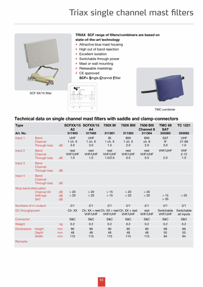
55
OUTDC
Rest VHF/UHFUHF CH XX
FILTER TYPE:
TRIAX
Triax single channel mast filters
TRIAX SCF range of filters/combiners are based on state-of-the-art technology • Attractive blue mast housing • High out of band rejection• Excellent isolation• Switchable through power• Mast or wall mounting• Releasable maststrap• CE approved SCF= Single Channel Filter
Technical data on single channel mast filters with saddle and clamp-connectors
SCF XX/15 filter
TMC combiner
Type
Art. No.
SCFXX/15 A2
317403
SCFXX/15 A4
317405
750X BI
311301
750X BIII
311303
7508 BIIIChannel 8
311304
TMC 69 SAT
333383
TC 1221
333582
Input 1 Band Channel Through loss dB
UHF1 ch. X
3.0
UHF1 ch. X
3.0
BI1 ch. X
1.5
BIIII1 ch. X
2.0
BIIIIch. 82.0
SATIF
3.0
UHF21-69
1.0
Input 2 Band Channel Through loss dB
restVHF/UHF
1.0
restVHF/UHF
1.0
restVHF/UHF
1.0/2.0
restVHF/UHF
0.5
restVHF/UHF
0.5
VHF/UHF
2.0
VHF2-121.0
Input 3 Band Channel Through loss dB
Input 4 Band Channel Through loss dB
Stop band attenuation Channel XX VHF/rest SAT
dBdBdB
> 20> 20
> 20> 20
> 15> 15
> 20> 20
> 20> 20 > 15
> 35> 20
Numbers of in-/output 2/1 2/1 2/1 2/1 2/1 2/1 2/1
DC throughpower Ch. XX Ch. XX + restVHF/UHF
Ch. XX + restVHF/UHF
Ch. XX + restVHF/UHF
restVHF/UHF
SwitchableVHF/UHF
Switchable all inputs
Connector S&C S&C S&C S&C S&C S&C S&C
Weight kg 0.2 0.2 0.2 0.2 0.2 0.2 0.2
Dimensions Height Depth Width
mmmmmm
9048115
9048
115
9048
115
9048
115
9048
115
695594
695594
Remarks

56
Technical data on single channel mast filters with saddle and clamp-connectors
TRIAX range of filtersWhen you are using the UHF series with the XX and YY channels you must remember that there must be 2 unused channels between your specified XX and YY UHF channels.
Triax single channel mast filters
Type
Art. No.
71234
311122
7132 G
311125
75132
311140
TC 335 DC VHF331381
TC 335 DC both331382
TC 356DC SAT331383
Input 1 Band Channel Through loss dB
UHF21-69
0.5
TV2-691.0
UHF21-69
2.0
UHF21-69
1.0
UHF21-69
1.0
TV2-692.0
Input 2 Band Channel Through loss dB
BIII5-120.5
FM
1.0
FM
0.5
VHF2-121.0
VHF2-121.0
SATIF
3.0
Input 3 Band Channel Through loss dB
FM
0.5
BI/BIII2-121.0
Input 4 Band Channel Through loss dB
BI2-40.5
Stop band attenuation VHF/BI FM BIII UHF SAT
dBdBdBdBdB
> 20> 12> 25> 30
> 20
> 20
> 20
> 40> 20 > 20 > 15
> 35
Numbers of in-/output 4/1 2/1 3/1 2/1 2/1 2/1
DC throughpower Switchable 1 of theinputs
UHF VHF SwitchableVHF/UHF
SAT
Connector S&C S&C S&C S&C S&C S&C
Weight kg 0.2 0.2 0.2 0.2 0.2 0.2
Dimensions Height Depth Width
mmmmmm
9048115
9048
115
9048
115
695594
695594
695594
Remarks
70000 mast filter
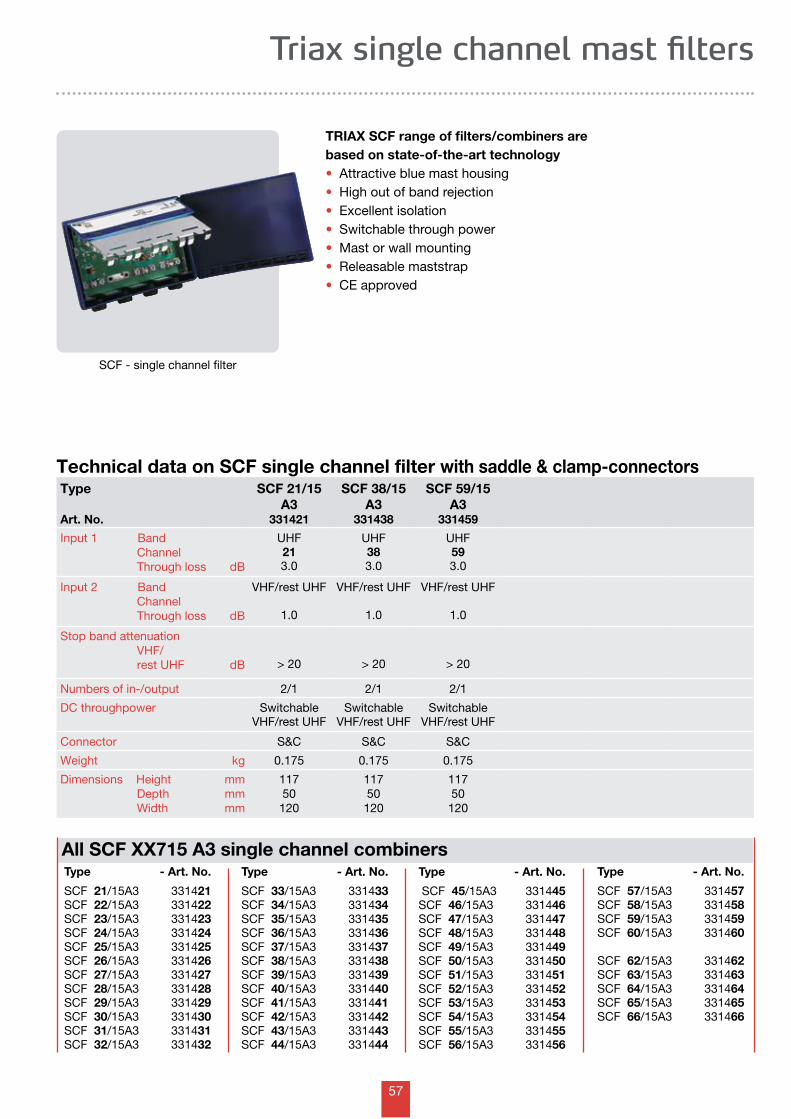
57
Triax single channel mast filters
Technical data on SCF single channel filter with saddle & clamp-connectors
TRIAX SCF range of filters/combiners are based on state-of-the-art technology • Attractive blue mast housing • High out of band rejection• Excellent isolation• Switchable through power• Mast or wall mounting• Releasable maststrap• CE approved
SCF - single channel filter
Type
Art. No.
SCF 21/15A3
331421
SCF 38/15A3
331438
SCF 59/15A3
331459
Input 1 Band Channel Through loss dB
UHF213.0
UHF383.0
UHF593.0
Input 2 Band Channel Through loss dB
VHF/rest UHF
1.0
VHF/rest UHF
1.0
VHF/rest UHF
1.0
Stop band attenuation VHF/ rest UHF dB > 20 > 20 > 20
Numbers of in-/output 2/1 2/1 2/1
DC throughpower SwitchableVHF/rest UHF
SwitchableVHF/rest UHF
SwitchableVHF/rest UHF
Connector S&C S&C S&C
Weight kg 0.175 0.175 0.175
Dimensions Height Depth Width
mmmmmm
11750120
11750
120
11750
120
Type - Art. No.
SCF 57/15A3 331457SCF 58/15A3 331458SCF 59/15A3 331459SCF 60/15A3 331460
SCF 62/15A3 331462SCF 63/15A3 331463SCF 64/15A3 331464SCF 65/15A3 331465SCF 66/15A3 331466
Type - Art. No.
SCF 21/15A3 331421SCF 22/15A3 331422SCF 23/15A3 331423SCF 24/15A3 331424SCF 25/15A3 331425SCF 26/15A3 331426SCF 27/15A3 331427SCF 28/15A3 331428SCF 29/15A3 331429SCF 30/15A3 331430SCF 31/15A3 331431SCF 32/15A3 331432
Type - Art. No.
SCF 33/15A3 331433SCF 34/15A3 331434SCF 35/15A3 331435SCF 36/15A3 331436SCF 37/15A3 331437SCF 38/15A3 331438SCF 39/15A3 331439SCF 40/15A3 331440SCF 41/15A3 331441SCF 42/15A3 331442SCF 43/15A3 331443SCF 44/15A3 331444
Type - Art. No.
SCF 45/15A3 331445SCF 46/15A3 331446SCF 47/15A3 331447SCF 48/15A3 331448SCF 49/15A3 331449SCF 50/15A3 331450SCF 51/15A3 331451SCF 52/15A3 331452SCF 53/15A3 331453SCF 54/15A3 331454SCF 55/15A3 331455SCF 56/15A3 331456
All SCF XX715 A3 single channel combiners
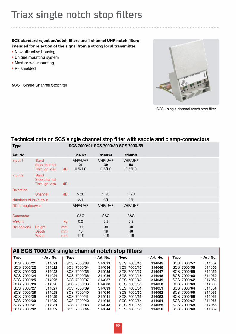
58
Triax single notch stop filters
Technical data on SCS single channel stop filter with saddle and clamp-connectors
SCS standard rejection/notch filters are 1 channel UHF notch filters intended for rejection of the signal from a strong local transmitter• New attractive housing• Unique mounting system• Mast or wall mounting• RF shielded
SCS= Single Channel Stopfilter
SCS - single channel notch stop filter
Type
Art. No.
SCS 7000/21
314021
SCS 7000/39
314039
SCS 7000/58
314058
Input 1 Band Stop channel Through loss dB
VHF/UHF21
0.5/1.0
VHF/UHF39
0.5/1.0
VHF/UHF58
0.5/1.0
Input 2 Band Stop channel Through loss dB
Rejection Channel dB > 20 > 20 > 20
Numbers of in-/output 2/1 2/1 2/1
DC throughpower VHF/UHF VHF/UHF VHF/UHF
Connector S&C S&C S&C
Weight kg 0.2 0.2 0.2
Dimensions Height Depth Width
mmmmmm
9048115
9048
115
9048
115
Type - Art. No.
SCS 7000/57 314057SCS 7000/58 314058SCS 7000/59 314059SCS 7000/60 314060SCS 7000/62 314062SCS 7000/63 314063SCS 7000/64 314054SCS 7000/65 314065SCS 7000/66 314066SCS 7000/67 314067SCS 7000/68 314068SCS 7000/69 314069
Type - Art. No.
SCS 7000/21 314021SCS 7000/22 314022SCS 7000/23 314023SCS 7000/24 314024SCS 7000/25 314025SCS 7000/26 314026SCS 7000/27 314027SCS 7000/28 314028SCS 7000/29 314029SCS 7000/30 314030SCS 7000/31 314031SCS 7000/32 314032
Type - Art. No.
SCS 7000/33 314033SCS 7000/34 314034SCS 7000/35 314035SCS 7000/36 314036SCS 7000/37 314037SCS 7000/38 314038SCS 7000/39 314039SCS 7000/40 314040SCS 7000/41 314041SCS 7000/42 314042SCS 7000/43 314043SCS 7000/44 314044
Type - Art. No.
SCS 7000/45 314045SCS 7000/46 314046SCS 7000/47 314047SCS 7000/48 314048SCS 7000/49 314049SCS 7000/50 314050SCS 7000/51 314051SCS 7000/52 314052SCS 7000/53 314053SCS 7000/54 314054SCS 7000/55 314055SCS 7000/56 314056
All SCS 7000/XX single channel notch stop filters
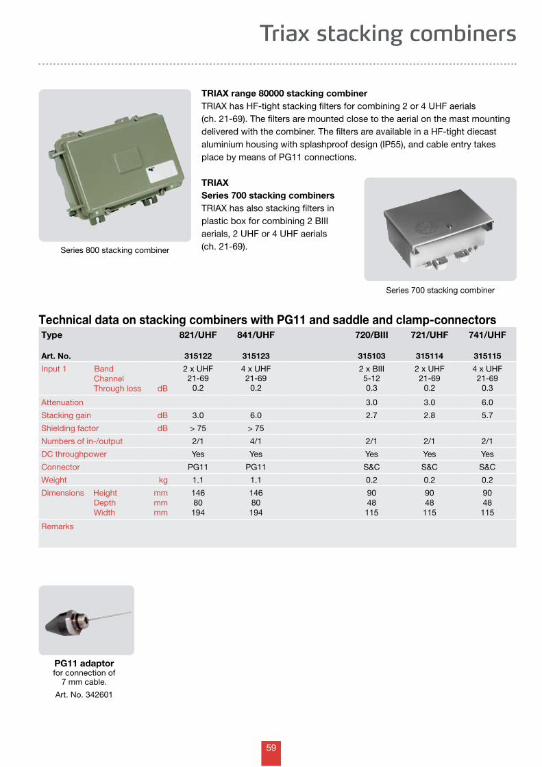
59
PG11 adaptor for connection of
7 mm cable.
Art. No. 342601
Technical data on stacking combiners with PG11 and saddle and clamp-connectors
TRIAX range 80000 stacking combiner TRIAX has HF-tight stacking filters for combining 2 or 4 UHF aerials (ch. 21-69). The filters are mounted close to the aerial on the mast mounting delivered with the combiner. The filters are available in a HF-tight diecast aluminium housing with splashproof design (IP55), and cable entry takes place by means of PG11 connections.
TRIAX Series 700 stacking combinersTRIAX has also stacking filters in plastic box for combining 2 BIII aerials, 2 UHF or 4 UHF aerials (ch. 21-69).
Type
Art. No.
821/UHF
315122
841/UHF
315123
720/BIII
315103
721/UHF
315114
741/UHF
315115
Input 1 Band Channel Through loss dB
2 x UHF21-69
0.2
4 x UHF21-69
0.2
2 x BIII5-120.3
2 x UHF21-69
0.2
4 x UHF21-69
0.3
Attenuation 3.0 3.0 6.0
Stacking gain dB 3.0 6.0 2.7 2.8 5.7
Shielding factor dB > 75 > 75
Numbers of in-/output 2/1 4/1 2/1 2/1 2/1
DC throughpower Yes Yes Yes Yes Yes
Connector PG11 PG11 S&C S&C S&C
Weight kg 1.1 1.1 0.2 0.2 0.2
Dimensions Height Depth Width
mmmmmm
14680194
14680
194
9048
115
9048
115
9048
115
Remarks
Series 700 stacking combiner
Triax stacking combiners
Series 800 stacking combiner
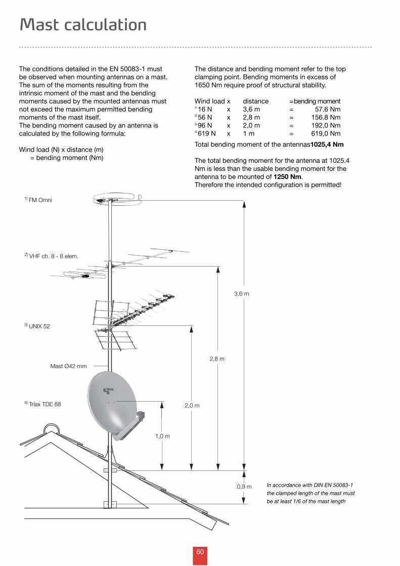
60
1,0 m
2,8 m
0,9 m
4) Triax TDE 88
3) UNIX 52
2) VHF ch. 8 - 8 elem.
Mast Ø42 mm
2,0 m
3,6 m
1) FM Omni
The conditions detailed in the EN 50083-1 must be observed when mounting antennas on a mast. The sum of the moments resulting from the intrinsic moment of the mast and the bending moments caused by the mount ed antennas must not exceed the maximum permitted bending moments of the mast itself. The bending moment caused by an antenna is calculated by the following formula:
Wind load (N) x distance (m) = bending moment (Nm)
The distance and bending moment refer to the top clamping point. Bending moments in excess of 1650 Nm require proof of structural stability.
Wind load x distance = bending moment 1) 16 N x 3,6 m = 57.6 Nm2) 56 N x 2,8 m = 156.8 Nm3) 96 N x 2,0 m = 192,0 Nm4) 619 N x 1 m = 619,0 Nm
Total bending moment of the antennas 1025,4 Nm
The total bending moment for the antenna at 1025.4 Nm is less than the usable bending moment for the antenna to be mounted of 1250 Nm. Therefore the intended configuration is permitted!
In accordance with DIN EN 50083-1
the clamped length of the mast must
be at least 1/6 of the mast length
Mast calculation
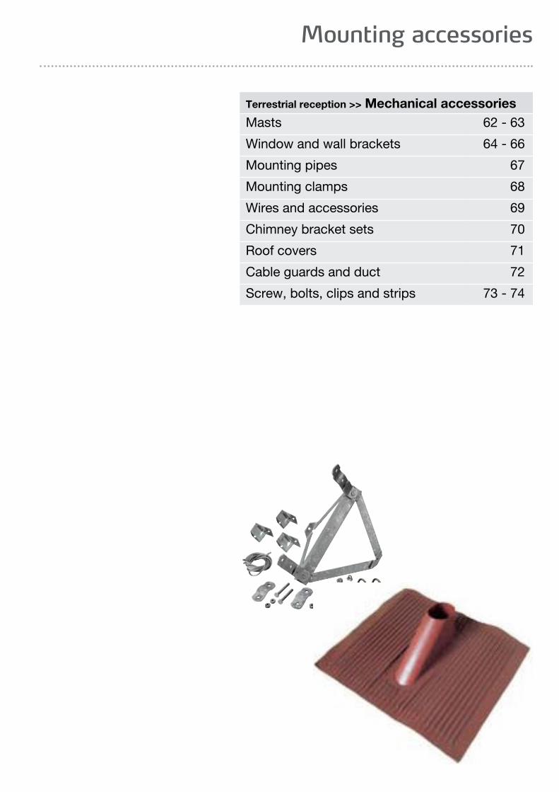
61
Mounting accessories
Terrestrial reception >> Mechanical accessoriesMasts 62 - 63
Window and wall brackets 64 - 66
Mounting pipes 67
Mounting clamps 68
Wires and accessories 69
Chimney bracket sets 70
Roof covers 71
Cable guards and duct 72
Screw, bolts, clips and strips 73 - 74
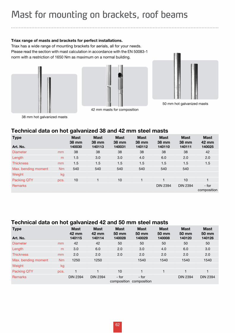
62
Mast for mounting on brackets, roof beams
Triax range of masts and brackets for perfect installations.Triax has a wide range of mounting brackets for aerials, all for your needs.Please read the section with mast calculation in accordance with the EN 50083-1 norm with a restriction of 1650 Nm as maximum on a normal building.
Technical data on hot galvanized 42 and 50 mm steel masts
Technical data on hot galvanized 38 and 42 mm steel mastsType
Art. No.
Mast38 mm140030
Mast38 mm140113
Mast38 mm140031
Mast38 mm140112
Mast38 mm140110
Mast38 mm140111
Mast42 mm140025
Diameter mm 38 38 38 38 38 38 42
Length m 1.5 3.0 3.0 4.0 6.0 2.0 2.0
Thickness mm 1.5 1.5 1.5 1.5 1.5 1.5 1.5
Max. bending moment Nm 540 540 540 540 540 540
Weight kg
Packing QTY pcs. 10 1 10 1 1 10 1
Remarks DIN 2394 DIN 2394 - for composition
Type
Art. No.
Mast42 mm140115
Mast42 mm140114
Mast50 mm140028
Mast50 mm140029
Mast50 mm140008
Mast50 mm140120
Mast50 mm140126
Diameter mm 42 42 50 50 50 50 50
Length m 3.0 6.0 2.0 3.0 4.0 6.0 3.0
Thickness mm 2.0 2.0 2.0 2.0 2.0 2.0 2.0
Max. bending moment Nm 1250 1250 1540 1540 1540 1540
Weight kg
Packing QTY pcs. 1 1 10 1 1 1 1
Remarks DIN 2394 DIN 2394 - for composition
- for composition
DIN 2394 DIN 2394
38 mm hot galvanized masts
42 mm masts for composition
50 mm hot galvanized masts
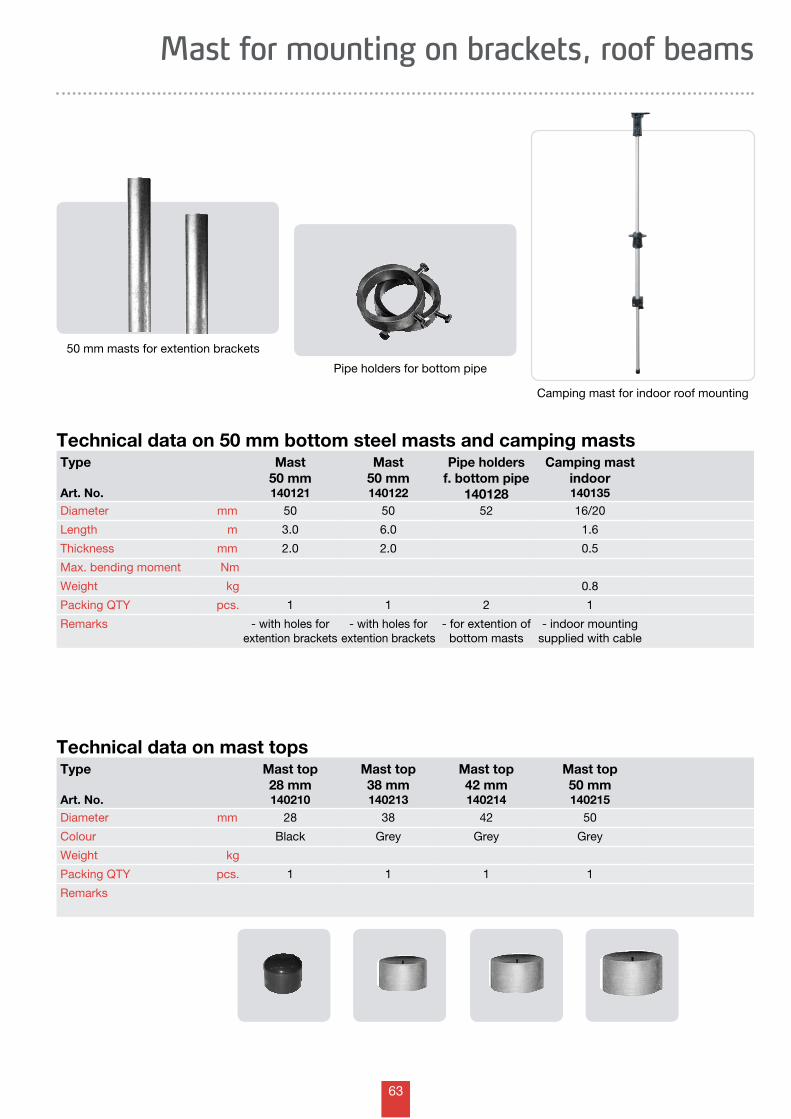
63
Mast for mounting on brackets, roof beams
Technical data on mast tops
Technical data on 50 mm bottom steel masts and camping masts
50 mm masts for extention brackets
Camping mast for indoor roof mounting
Type
Art. No.
Mast50 mm140121
Mast50 mm140122
Pipe holdersf. bottom pipe
140128
Camping mastindoor140135
Diameter mm 50 50 52 16/20
Length m 3.0 6.0 1.6
Thickness mm 2.0 2.0 0.5
Max. bending moment Nm
Weight kg 0.8
Packing QTY pcs. 1 1 2 1
Remarks - with holes forextention brackets
- with holes forextention brackets
- for extention ofbottom masts
- indoor mounting supplied with cable
Pipe holders for bottom pipe
Type
Art. No.
Mast top28 mm140210
Mast top38 mm140213
Mast top42 mm140214
Mast top50 mm140215
Diameter mm 28 38 42 50
Colour Black Grey Grey Grey
Weight kg
Packing QTY pcs. 1 1 1 1
Remarks
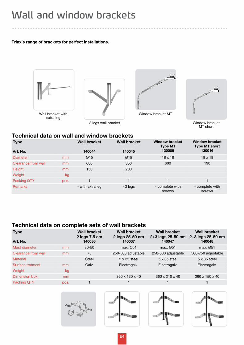
64
Wall and window brackets
Triax’s range of brackets for perfect installations.
Technical data on complete sets of wall brackets
Technical data on wall and window brackets
Wall bracket with extra leg
3 legs wall bracket
Type
Art. No.
Wall bracket
140044
Wall bracket
140045
Window bracketType MT 130009
Window bracketType MT short
130016
Diameter mm Ø15 Ø15 18 x 18 18 x 18
Clearance from wall mm 600 350 600 190
Height mm 150 200
Weight kg
Packing QTY pcs. 1 1 1 1
Remarks - with extra leg - 3 legs - complete withscrews
- complete withscrews
Window bracket MT
Window bracket MT short
Type
Art. No.
Wall bracket2 legs 7.5 cm
140036
Wall bracket2 legs 25-50 cm
140037
Wall bracket2+3 legs 25-50 cm
140047
Wall bracket2+3 legs 25-50 cm
140048
Mast diameter mm 30-50 max. Ø51 max. Ø51 max. Ø51
Clearance from wall mm 75 250-500 adjustable 250-500 adjustable 500-750 adjustable
Material Steel 5 x 35 steel 5 x 35 steel 5 x 35 steel
Surface tratment mm Galv. Electrogalv. Electrogalv. Electrogalv.
Weight kg
Dimension box mm 360 x 130 x 40 360 x 210 x 40 360 x 150 x 40
Packing QTY pcs. 1 1 1 1
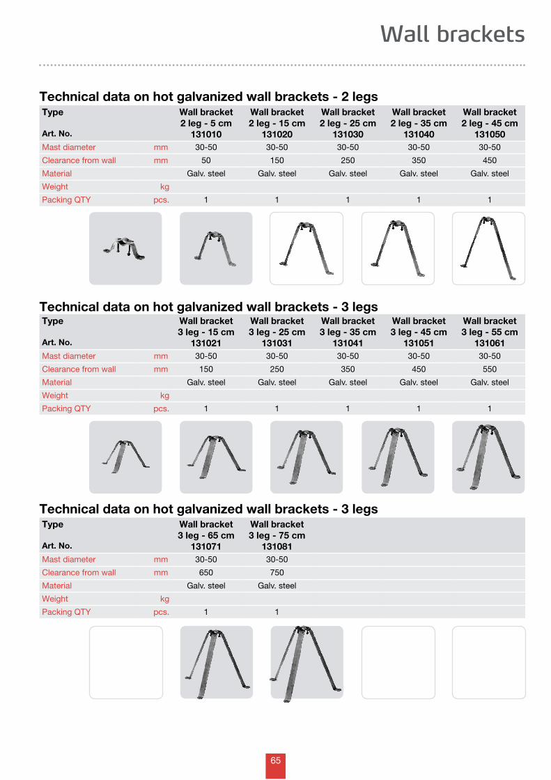
65
Wall brackets
Technical data on hot galvanized wall brackets - 2 legs
Technical data on hot galvanized wall brackets - 3 legs
Technical data on hot galvanized wall brackets - 3 legs
Type
Art. No.
Wall bracket2 leg - 5 cm
131010
Wall bracket2 leg - 15 cm
131020
Wall bracket2 leg - 25 cm
131030
Wall bracket2 leg - 35 cm
131040
Wall bracket2 leg - 45 cm
131050Mast diameter mm 30-50 30-50 30-50 30-50 30-50
Clearance from wall mm 50 150 250 350 450
Material Galv. steel Galv. steel Galv. steel Galv. steel Galv. steel
Weight kg
Packing QTY pcs. 1 1 1 1 1
Type
Art. No.
Wall bracket3 leg - 15 cm
131021
Wall bracket3 leg - 25 cm
131031
Wall bracket3 leg - 35 cm
131041
Wall bracket3 leg - 45 cm
131051
Wall bracket3 leg - 55 cm
131061Mast diameter mm 30-50 30-50 30-50 30-50 30-50
Clearance from wall mm 150 250 350 450 550
Material Galv. steel Galv. steel Galv. steel Galv. steel Galv. steel
Weight kg
Packing QTY pcs. 1 1 1 1 1
Type
Art. No.
Wall bracket3 leg - 65 cm
131071
Wall bracket3 leg - 75 cm
131081Mast diameter mm 30-50 30-50
Clearance from wall mm 650 750
Material Galv. steel Galv. steel
Weight kg
Packing QTY pcs. 1 1
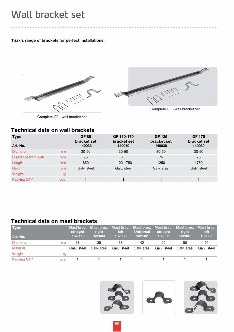
66
Wall bracket set
Triax’s range of brackets for perfect installations.
Technical data on wall brackets
Complete GF - wall bracket set
Type
Art. No.
GF 85bracket set
140033
GF 110-170bracket set
140040
GF 125bracket set
140038
GF 175bracket set
140039
Diameter mm 30-50 30-50 30-50 30-50
Clearance from wall mm 75 75 75 75
Length mm 850 1100-1750 1250 1750
Height mm Galv. steel Galv. steel Galv. steel Galv. steel
Weight kg
Packing QTY pcs. 1 1 1 1
Technical data on mast bracketsType
Art. No.
Mast brac. straight132003
Mast brac. right
132004
Mast brac. left
132005
Mast brac. Universal132102
Mast brac. straight132006
Mast brac. right
132007
Mast brac. left
132008
Diameter mm 38 38 38 42 50 50 50
Material Galv. steel Galv. steel Galv. steel Galv. steel Galv. steel Galv. steel Galv. steel
Weight kg
Packing QTY pcs. 1 1 1 1 1 1 1
Complete GF - wall bracket set
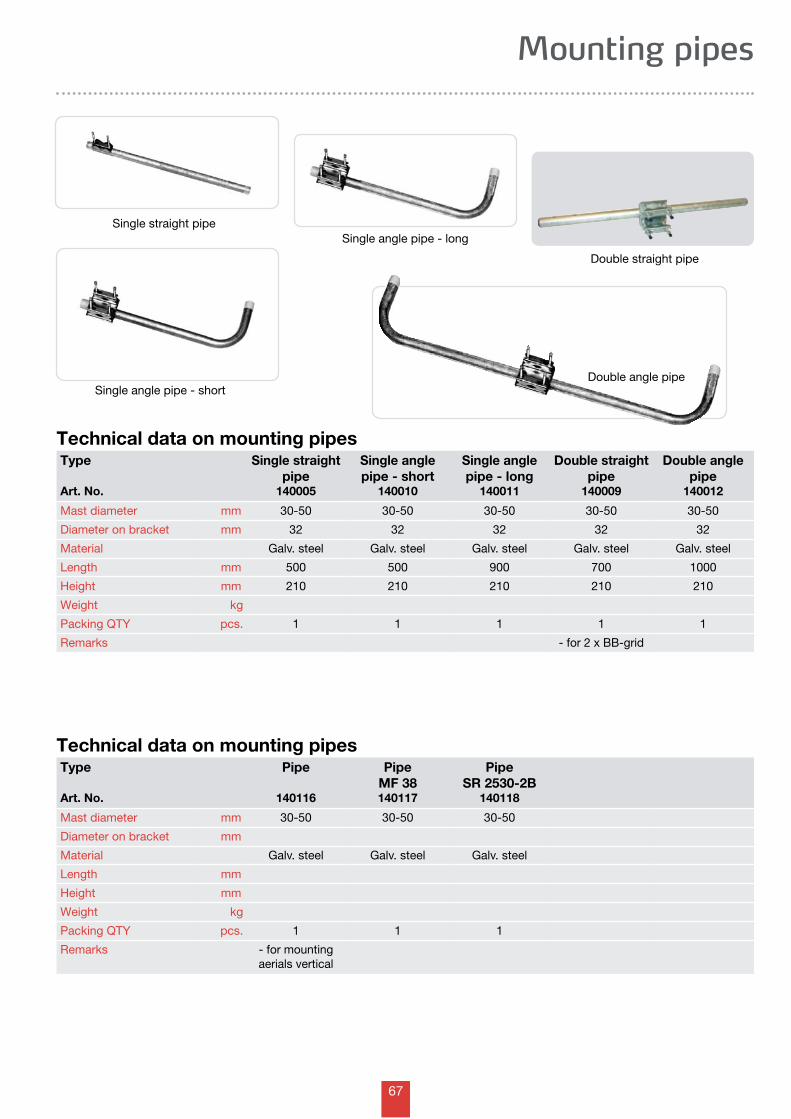
67
Mounting pipes
Technical data on mounting pipes
Single straight pipe
Single angle pipe - short
Single angle pipe - long
Double straight pipe
Double angle pipe
Type
Art. No.
Single straightpipe
140005
Single anglepipe - short
140010
Single anglepipe - long
140011
Double straightpipe
140009
Double anglepipe
140012
Mast diameter mm 30-50 30-50 30-50 30-50 30-50
Diameter on bracket mm 32 32 32 32 32
Material Galv. steel Galv. steel Galv. steel Galv. steel Galv. steel
Length mm 500 500 900 700 1000
Height mm 210 210 210 210 210
Weight kg
Packing QTY pcs. 1 1 1 1 1
Remarks - for 2 x BB-grid
Technical data on mounting pipesType
Art. No.
Pipe
140116
PipeMF 38140117
PipeSR 2530-2B
140118
Mast diameter mm 30-50 30-50 30-50
Diameter on bracket mm
Material Galv. steel Galv. steel Galv. steel
Length mm
Height mm
Weight kg
Packing QTY pcs. 1 1 1
Remarks - for mountingaerials vertical
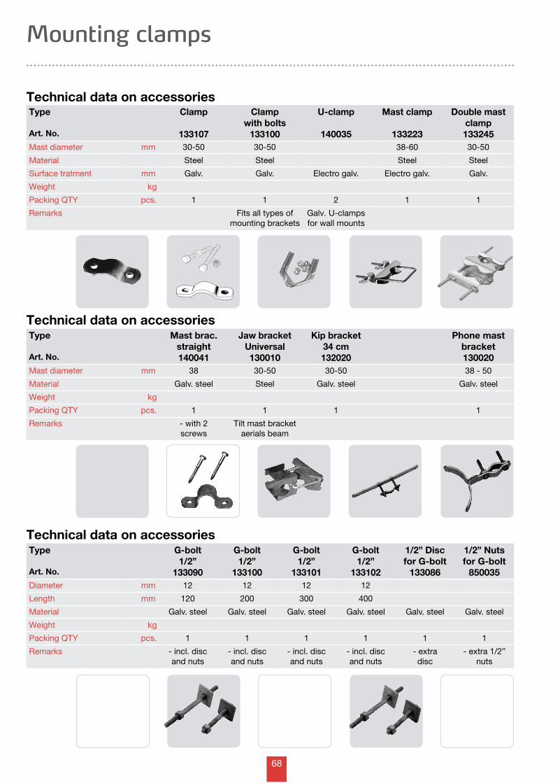
68
Mounting clamps
Technical data on accessoriesType
Art. No.
Clamp
133107
Clampwith bolts
133100
U-clamp
140035
Mast clamp
133223
Double mast clamp133245
Mast diameter mm 30-50 30-50 38-60 30-50
Material Steel Steel Steel Steel
Surface tratment mm Galv. Galv. Electro galv. Electro galv. Galv.
Weight kg
Packing QTY pcs. 1 1 2 1 1
Remarks Fits all types of mounting brackets
Galv. U-clamps for wall mounts
Technical data on accessoriesType
Art. No.
Mast brac. straight140041
Jaw bracketUniversal130010
Kip bracket34 cm132020
Phone mastbracket130020
Mast diameter mm 38 30-50 30-50 38 - 50
Material Galv. steel Steel Galv. steel Galv. steel
Weight kg
Packing QTY pcs. 1 1 1 1
Remarks - with 2 screws
Tilt mast bracketaerials beam
Type
Art. No.
G-bolt1/2”
133090
G-bolt1/2”
133100
G-bolt1/2”
133101
G-bolt1/2”
133102
1/2” Disc for G-bolt
133086
1/2” Nuts for G-bolt
850035Diameter mm 12 12 12 12
Length mm 120 200 300 400
Material Galv. steel Galv. steel Galv. steel Galv. steel Galv. steel Galv. steel
Weight kg
Packing QTY pcs. 1 1 1 1 1 1
Remarks - incl. disc and nuts
- incl. disc and nuts
- incl. disc and nuts
- incl. disc and nuts
- extradisc
- extra 1/2”nuts
Technical data on accessories
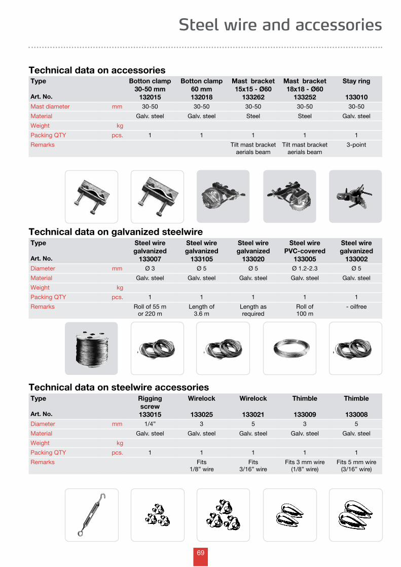
69
Steel wire and accessories
Technical data on accessories
Technical data on steelwire accessories
Technical data on galvanized steelwire
Type
Art. No.
Botton clamp30-50 mm
132015
Botton clamp60 mm132018
Mast bracket15x15 - Ø60
133262
Mast bracket18x18 - Ø60
133252
Stay ring
133010Mast diameter mm 30-50 30-50 30-50 30-50 30-50
Material Galv. steel Galv. steel Steel Steel Galv. steel
Weight kg
Packing QTY pcs. 1 1 1 1 1
Remarks Tilt mast bracketaerials beam
Tilt mast bracketaerials beam
3-point
Type
Art. No.
Steel wiregalvanized
133007
Steel wiregalvanized
133105
Steel wiregalvanized
133020
Steel wirePVC-covered
133005
Steel wiregalvanized
133002Diameter mm Ø 3 Ø 5 Ø 5 Ø 1.2-2.3 Ø 5
Material Galv. steel Galv. steel Galv. steel Galv. steel Galv. steel
Weight kg
Packing QTY pcs. 1 1 1 1 1
Remarks Roll of 55 mor 220 m
Length of 3.6 m
Length asrequired
Roll of 100 m
- oilfree
Type
Art. No.
Riggingscrew133015
Wirelock
133025
Wirelock
133021
Thimble
133009
Thimble
133008Diameter mm 1/4” 3 5 3 5
Material Galv. steel Galv. steel Galv. steel Galv. steel Galv. steel
Weight kg
Packing QTY pcs. 1 1 1 1 1
Remarks Fits1/8” wire
Fits3/16” wire
Fits 3 mm wire(1/8” wire)
Fits 5 mm wire(3/16” wire)
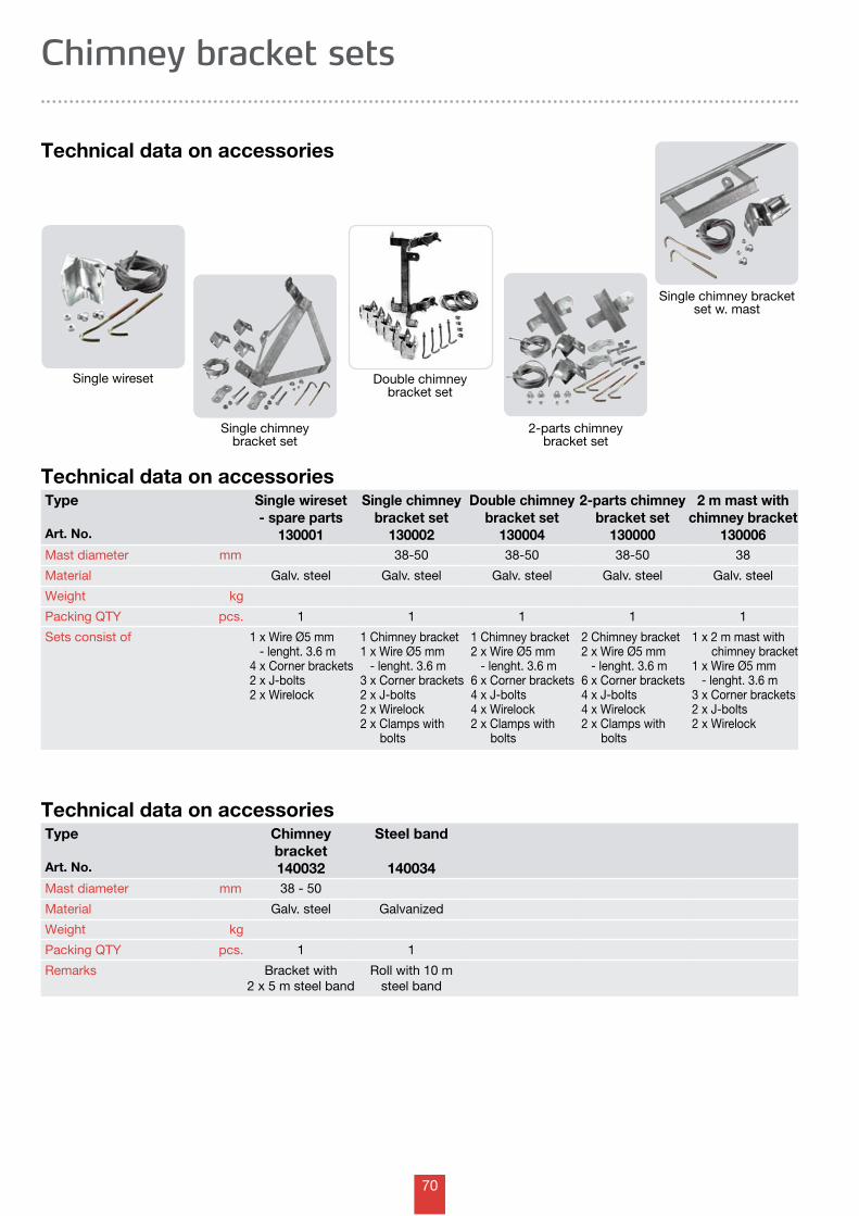
70
Type
Art. No.
Single wireset- spare parts
130001
Single chimneybracket set
130002
Double chimneybracket set
130004
2-parts chimneybracket set
130000
2 m mast withchimney bracket
130006Mast diameter mm 38-50 38-50 38-50 38
Material Galv. steel Galv. steel Galv. steel Galv. steel Galv. steel
Weight kg
Packing QTY pcs. 1 1 1 1 1
Sets consist of 1 x Wire Ø5 mm - lenght. 3.6 m4 x Corner brackets2 x J-bolts2 x Wirelock
1 Chimney bracket1 x Wire Ø5 mm - lenght. 3.6 m3 x Corner brackets2 x J-bolts2 x Wirelock2 x Clamps with bolts
1 Chimney bracket2 x Wire Ø5 mm - lenght. 3.6 m6 x Corner brackets4 x J-bolts4 x Wirelock2 x Clamps with bolts
2 Chimney bracket2 x Wire Ø5 mm - lenght. 3.6 m6 x Corner brackets4 x J-bolts4 x Wirelock2 x Clamps with bolts
1 x 2 m mast with chimney bracket1 x Wire Ø5 mm - lenght. 3.6 m3 x Corner brackets2 x J-bolts2 x Wirelock
Chimney bracket sets
Technical data on accessories
Technical data on accessories
Single wireset
Single chimney bracket set
Single chimney bracket set w. mast
Double chimney bracket set
2-parts chimney bracket set
Technical data on accessoriesType
Art. No.
Chimney bracket140032
Steel band
140034Mast diameter mm 38 - 50
Material Galv. steel Galvanized
Weight kg
Packing QTY pcs. 1 1
Remarks Bracket with 2 x 5 m steel band
Roll with 10 m steel band
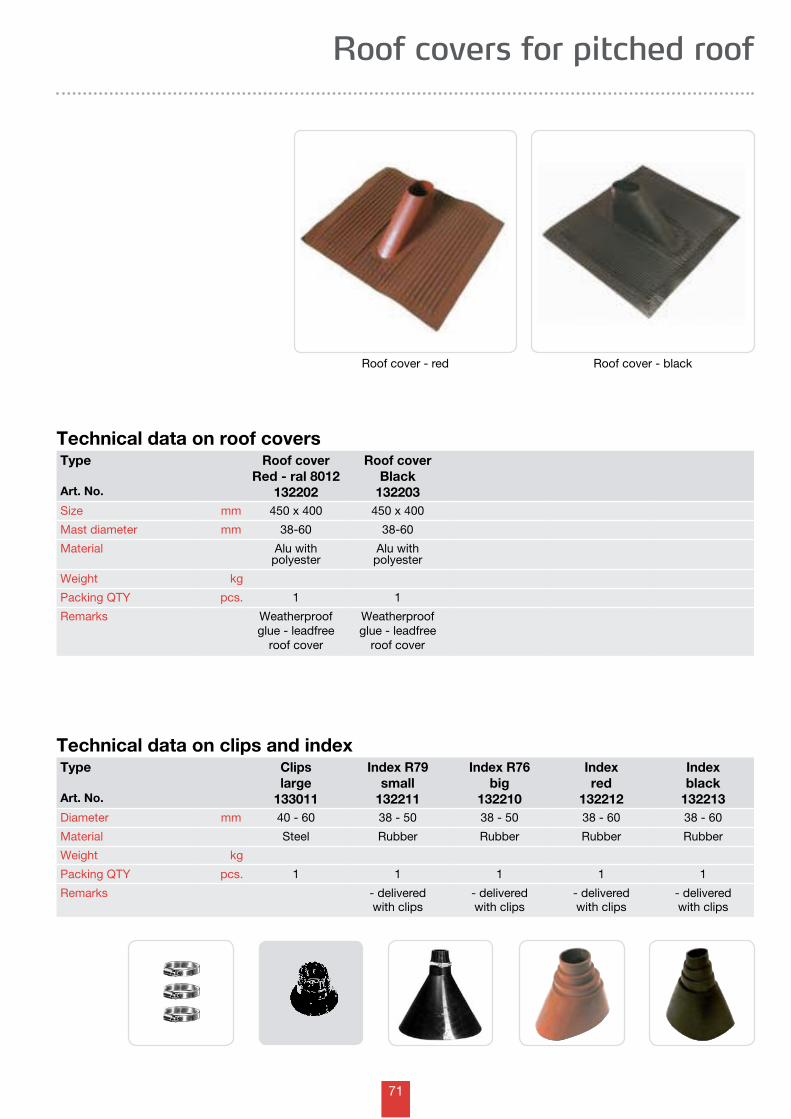
71
Roof covers for pitched roof
Technical data on clips and index
Technical data on roof coversType
Art. No.
Roof coverRed - ral 8012
132202
Roof coverBlack
132203Size mm 450 x 400 450 x 400
Mast diameter mm 38-60 38-60
Material Alu withpolyester
Alu withpolyester
Weight kg
Packing QTY pcs. 1 1
Remarks Weatherproofglue - leadfree
roof cover
Weatherproofglue - leadfree
roof cover
Type
Art. No.
Clipslarge
133011
Index R79small
132211
Index R76big
132210
Indexred
132212
Indexblack
132213Diameter mm 40 - 60 38 - 50 38 - 50 38 - 60 38 - 60
Material Steel Rubber Rubber Rubber Rubber
Weight kg
Packing QTY pcs. 1 1 1 1 1
Remarks - deliveredwith clips
- deliveredwith clips
- deliveredwith clips
- deliveredwith clips
Roof cover - red Roof cover - black
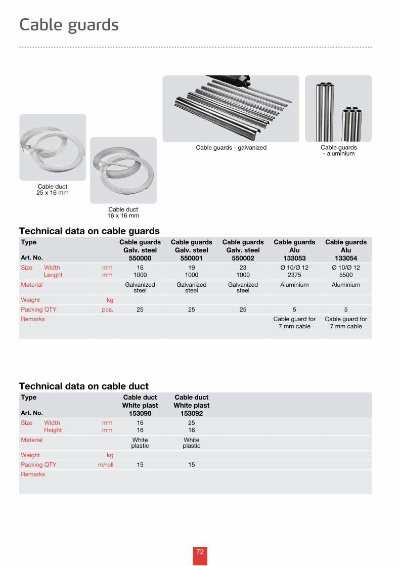
72
Technical data on cable guardsType
Art. No.
Cable guardsGalv. steel
550000
Cable guardsGalv. steel
550001
Cable guardsGalv. steel
550002
Cable guardsAlu
133053
Cable guardsAlu
133054Size Width Lenght
mmmm
161000
191000
231000
Ø 10/Ø 122375
Ø 10/Ø 125500
Material Galvanizedsteel
Galvanizedsteel
Galvanizedsteel
Aluminium Aluminium
Weight kg
Packing QTY pcs. 25 25 25 5 5
Remarks Cable guard for7 mm cable
Cable guard for7 mm cable
Cable guards
Technical data on cable duct
Cable duct25 x 16 mm
Cable guards - galvanized
Cable duct16 x 16 mm
Cable guards - aluminium
Type
Art. No.
Cable ductWhite plast
153090
Cable ductWhite plast
153092Size Width Height
mmmm
1616
2516
Material Whiteplastic
Whiteplastic
Weight kg
Packing QTY m/roll 15 15
Remarks
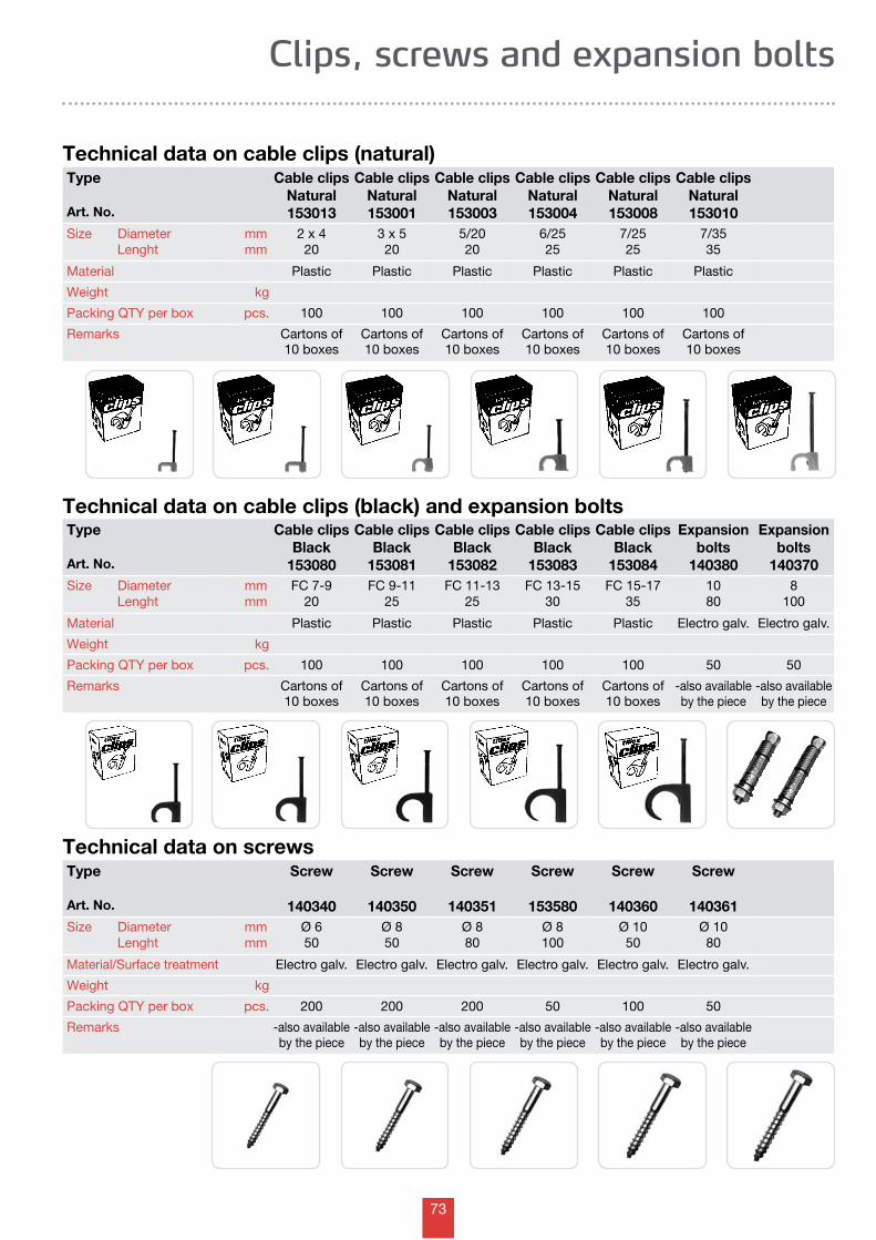
73
Technical data on cable clips (black) and expansion bolts
Clips, screws and expansion bolts
Technical data on screws
Technical data on cable clips (natural)
Type
Art. No.
Screw
140340
Screw
140350
Screw
140351
Screw
153580
Screw
140360
Screw
140361Size Diameter Lenght
mmmm
Ø 650
Ø 850
Ø 880
Ø 8100
Ø 1050
Ø 1080
Material/Surface treatment Electro galv. Electro galv. Electro galv. Electro galv. Electro galv. Electro galv.
Weight kg
Packing QTY per box pcs. 200 200 200 50 100 50
Remarks -also availableby the piece
-also availableby the piece
-also availableby the piece
-also availableby the piece
-also availableby the piece
-also availableby the piece
Type
Art. No.
Cable clipsNatural153013
Cable clipsNatural153001
Cable clipsNatural153003
Cable clipsNatural153004
Cable clipsNatural153008
Cable clipsNatural153010
Size Diameter Lenght
mmmm
2 x 420
3 x 520
5/2020
6/2525
7/2525
7/3535
Material Plastic Plastic Plastic Plastic Plastic Plastic
Weight kg
Packing QTY per box pcs. 100 100 100 100 100 100
Remarks Cartons of10 boxes
Cartons of10 boxes
Cartons of10 boxes
Cartons of10 boxes
Cartons of10 boxes
Cartons of10 boxes
Type
Art. No.
Cable clipsBlack
153080
Cable clipsBlack
153081
Cable clipsBlack
153082
Cable clipsBlack
153083
Cable clipsBlack
153084
Expansionbolts
140380
Expansionbolts
140370Size Diameter Lenght
mmmm
FC 7-920
FC 9-1125
FC 11-1325
FC 13-1530
FC 15-1735
1080
8100
Material Plastic Plastic Plastic Plastic Plastic Electro galv. Electro galv.
Weight kg
Packing QTY per box pcs. 100 100 100 100 100 50 50
Remarks Cartons of10 boxes
Cartons of10 boxes
Cartons of10 boxes
Cartons of10 boxes
Cartons of10 boxes
-also availableby the piece
-also availableby the piece
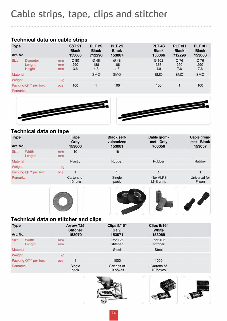
74
Cable strips, tape, clips and stitcher
Technical data on cable strips
Technical data on stitcher and clips
Technical data on tape
Type
Art. No.
SST 21Black
153065
PLT 2SBlack
712290
PLT 2SBlack
153067
PLT 4SBlack
153066
PLT 3HBlack
712296
PLT 3HBlack
153068Size Diameter Lenght Height
mmmmmm
Ø 802903.6
Ø 481884.8
Ø 481884.8
Ø 1023684.8
Ø 762907.6
Ø 762907.6
Material SMO SMO SMO SMO SMO
Weight kg
Packing QTY per box pcs. 100 1 100 100 1 100
Remarks
Type
Art. No.
TapeGrey
153060
Black self- vulcanized
153061
Cable grom-met - Grey
760056
Cable grom-met - Black
153057Size Width Lenght
mmmm
10 18
Material Plastic Rubber Rubber Rubber
Weight kg
Packing QTY per box pcs. 1 1 1 1
Remarks Cartons of10 rolls
Single pack
- for ALPSLNB units
Universal for F-con
Type
Art. No.
Arrow T25Stitcher153070
Clips 9/16”Galv.
153071
Clips 9/16”White
153069Size Width Lenght
mmmm
- for T25stitcher
- for T25stitcher
Material Steel Steel
Weight kg
Packing QTY per box pcs. 1 1000 1000
Remarks Single pack
Cartons of10 boxes
Cartons of10 boxes
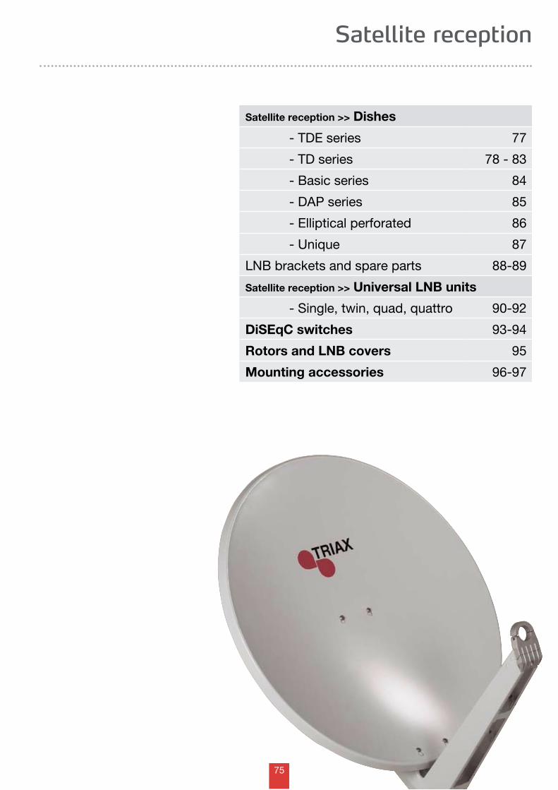
75
Satellite reception
Satellite reception >> Dishes
- TDE series 77
- TD series 78 - 83
- Basic series 84
- DAP series 85
- Elliptical perforated 86
- Unique 87
LNB brackets and spare parts 88-89
Satellite reception >> Universal LNB units
- Single, twin, quad, quattro 90-92
DiSEqC switches 93-94
Rotors and LNB covers 95
Mounting accessories 96-97
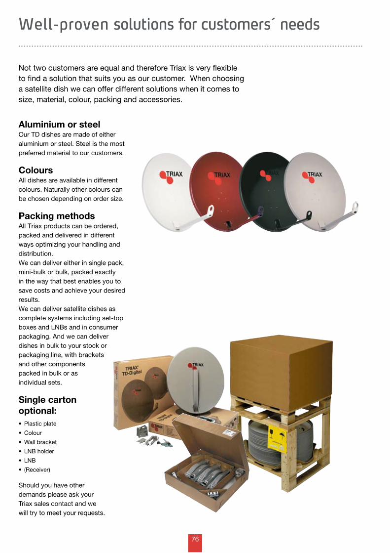
76
Not two customers are equal and therefore Triax is very flexible to find a solution that suits you as our customer. When choosinga satellite dish we can offer different solutions when it comes to size, material, colour, packing and accessories.
Well-proven solutions for customers´ needs
Aluminium or steelOur TD dishes are made of either aluminium or steel. Steel is the most preferred material to our customers.
ColoursAll dishes are available in different colours. Naturally other colours can be chosen depending on order size.
Packing methodsAll Triax products can be ordered, packed and delivered in different ways optimizing your handling and distribution. We can deliver either in single pack, mini-bulk or bulk, packed exactly in the way that best enables you to save costs and achieve your desired results.We can deliver satellite dishes as complete systems including set-top boxes and LNBs and in consumer packaging. And we can deliver dishes in bulk to your stock or packaging line, with brackets and other components packed in bulk or as individual sets.
Single carton optional: • Plasticplate
• Colour
• Wallbracket
• LNBholder
• LNB
• (Receiver)
Should you have other demands please ask your Triax sales contact and we will try to meet your requests.
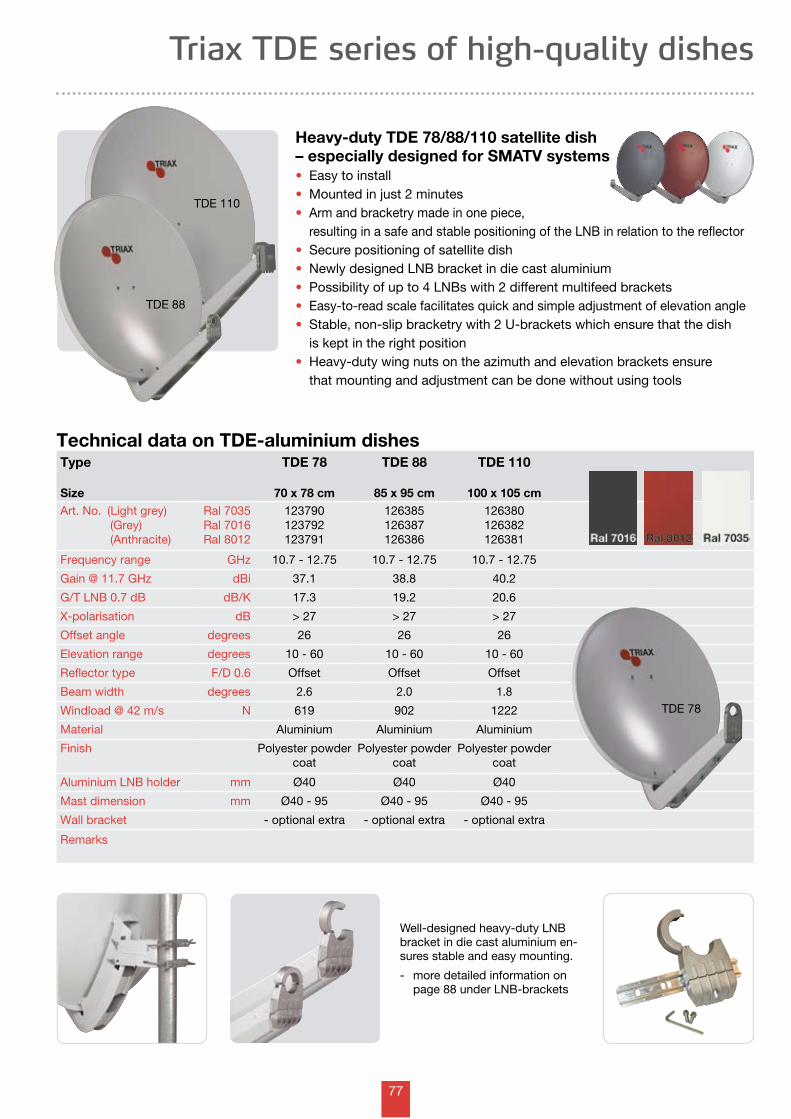
77
Triax TDE series of high-quality dishes
Heavy-duty TDE 78/88/110 satellite dish – especially designed for SMATV systems• Easy to install• Mounted in just 2 minutes • Arm and bracketry made in one piece, resulting in a safe and stable positioning of the LNB in relation to the reflector• Secure positioning of satellite dish• Newly designed LNB bracket in die cast aluminium• Possibility of up to 4 LNBs with 2 different multifeed brackets• Easy-to-read scale facilitates quick and simple adjustment of elevation angle• Stable, non-slip bracketry with 2 U-brackets which ensure that the dish is kept in the right position• Heavy-duty wing nuts on the azimuth and elevation brackets ensure that mounting and adjustment can be done without using tools
Well-designed heavy-duty LNB bracket in die cast aluminium en-sures stable and easy mounting.
- more detailed information on page 88 under LNB-brackets
Type
Size
TDE 78
70 x 78 cm
TDE 88
85 x 95 cm
TDE 110
100 x 105 cmArt. No. (Light grey) (Grey) (Anthracite)
Ral 7035Ral 7016Ral 8012
123790123792123791
126385126387126386
126380126382126381
Frequency range GHz 10.7 - 12.75 10.7 - 12.75 10.7 - 12.75
Gain @ 11.7 GHz dBi 37.1 38.8 40.2
G/T LNB 0.7 dB dB/K 17.3 19.2 20.6
X-polarisation dB > 27 > 27 > 27
Offset angle degrees 26 26 26
Elevation range degrees 10 - 60 10 - 60 10 - 60
Reflector type F/D 0.6 Offset Offset Offset
Beam width degrees 2.6 2.0 1.8
Windload @ 42 m/s N 619 902 1222
Material Aluminium Aluminium Aluminium
Finish Polyester powdercoat
Polyester powdercoat
Polyester powdercoat
Aluminium LNB holder mm Ø40 Ø40 Ø40
Mast dimension mm Ø40 - 95 Ø40 - 95 Ø40 - 95
Wall bracket - optional extra - optional extra - optional extra
Remarks
Technical data on TDE-aluminium dishes
TDE 88
TDE 110
TDE 78
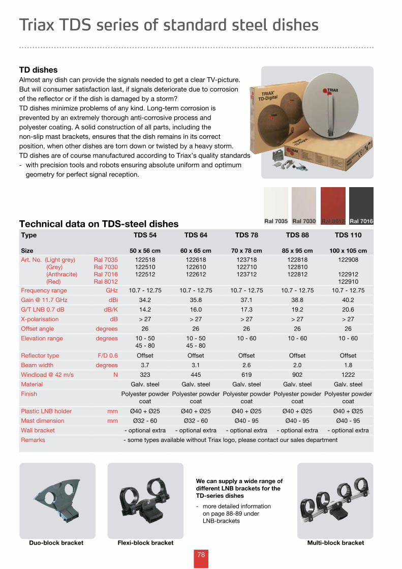
78
We can supply a wide range of different LNB brackets for the TD-series dishes
- more detailed information on page 88-89 under LNB-brackets
Technical data on TDS-steel dishesType
Size
TDS 54
50 x 56 cm
TDS 64
60 x 65 cm
TDS 78
70 x 78 cm
TDS 88
85 x 95 cm
TDS 110
100 x 105 cmArt. No. (Light grey) (Grey) (Anthracite) (Red)
Ral 7035Ral 7030Ral 7016Ral 8012
122518122510122512
122618122610122612
123718122710123712
122818122810122812
122908
122912122910
Frequency range GHz 10.7 - 12.75 10.7 - 12.75 10.7 - 12.75 10.7 - 12.75 10.7 - 12.75
Gain @ 11.7 GHz dBi 34.2 35.8 37.1 38.8 40.2
G/T LNB 0.7 dB dB/K 14.2 16.0 17.3 19.2 20.6
X-polarisation dB > 27 > 27 > 27 > 27 > 27
Offset angle degrees 26 26 26 26 26
Elevation range degrees 10 - 5045 - 80
10 - 5045 - 80
10 - 60 10 - 60 10 - 60
Reflector type F/D 0.6 Offset Offset Offset Offset Offset
Beam width degrees 3.7 3.1 2.6 2.0 1.8
Windload @ 42 m/s N 323 445 619 902 1222
Material Galv. steel Galv. steel Galv. steel Galv. steel Galv. steel
Finish Polyester powdercoat
Polyester powdercoat
Polyester powdercoat
Polyester powdercoat
Polyester powdercoat
Plastic LNB holder mm Ø40 + Ø25 Ø40 + Ø25 Ø40 + Ø25 Ø40 + Ø25 Ø40 + Ø25
Mast dimension mm Ø32 - 60 Ø32 - 60 Ø40 - 95 Ø40 - 95 Ø40 - 95
Wall bracket - optional extra - optional extra - optional extra - optional extra - optional extra
Remarks - some types available without Triax logo, please contact our sales department
Triax TDS series of standard steel dishes
TD dishesAlmost any dish can provide the signals needed to get a clear TV-picture. But will consumer satisfaction last, if signals deteriorate due to corrosion of the reflector or if the dish is damaged by a storm?TD dishes minimize problems of any kind. Long-term corrosion is prevented by an extremely thorough anti-corrosive process and polyester coating. A solid construction of all parts, including the non-slip mast brackets, ensures that the dish remains in its correct position, when other dishes are torn down or twisted by a heavy storm.TD dishes are of course manufactured according to Triax’s quality standards - with precision tools and robots ensuring absolute uniform and optimum geometry for perfect signal reception.
Duo-block bracket Flexi-block bracket Multi-block bracket
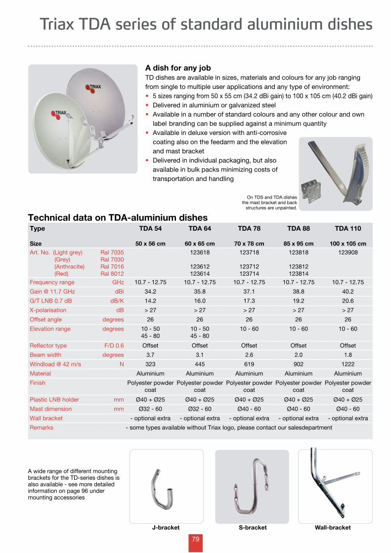
79
Triax TDA series of standard aluminium dishes
Technical data on TDA-aluminium dishesType
Size
TDA 54
50 x 56 cm
TDA 64
60 x 65 cm
TDA 78
70 x 78 cm
TDA 88
85 x 95 cm
TDA 110
100 x 105 cmArt. No. (Light grey) (Grey) (Anthracite) (Red)
Ral 7035Ral 7030Ral 7016Ral 8012
123618
123612123614
123718
123712123714
123818
123812123814
123908
Frequency range GHz 10.7 - 12.75 10.7 - 12.75 10.7 - 12.75 10.7 - 12.75 10.7 - 12.75
Gain @ 11.7 GHz dBi 34.2 35.8 37.1 38.8 40.2
G/T LNB 0.7 dB dB/K 14.2 16.0 17.3 19.2 20.6
X-polarisation dB > 27 > 27 > 27 > 27 > 27
Offset angle degrees 26 26 26 26 26
Elevation range degrees 10 - 5045 - 80
10 - 5045 - 80
10 - 60 10 - 60 10 - 60
Reflector type F/D 0.6 Offset Offset Offset Offset Offset
Beam width degrees 3.7 3.1 2.6 2.0 1.8
Windload @ 42 m/s N 323 445 619 902 1222
Material Aluminium Aluminium Aluminium Aluminium Aluminium
Finish Polyester powdercoat
Polyester powdercoat
Polyester powdercoat
Polyester powdercoat
Polyester powdercoat
Plastic LNB holder mm Ø40 + Ø25 Ø40 + Ø25 Ø40 + Ø25 Ø40 + Ø25 Ø40 + Ø25
Mast dimension mm Ø32 - 60 Ø32 - 60 Ø40 - 60 Ø40 - 60 Ø40 - 60
Wall bracket - optional extra - optional extra - optional extra - optional extra - optional extra
Remarks - some types available without Triax logo, please contact our salesdepartment
A dish for any jobTD dishes are available in sizes, materials and colours for any job ranging from single to multiple user applications and any type of environment:• 5 sizes ranging from 50 x 55 cm (34.2 dBi gain) to 100 x 105 cm (40.2 dBi gain)• Delivered in aluminium or galvanized steel• Available in a number of standard colours and any other colour and own label branding can be supplied against a minimum quantity• Available in deluxe version with anti-corrosive coating also on the feedarm and the elevation and mast bracket • Delivered in individual packaging, but also available in bulk packs minimizing costs of transportation and handling
A wide range of different mountingbrackets for the TD-series dishes is also available - see more detailed information on page 96 under mounting accessories
J-bracket S-bracket Wall-bracket
On TDS and TDA dishes the mast bracket and back
structures are unpainted.
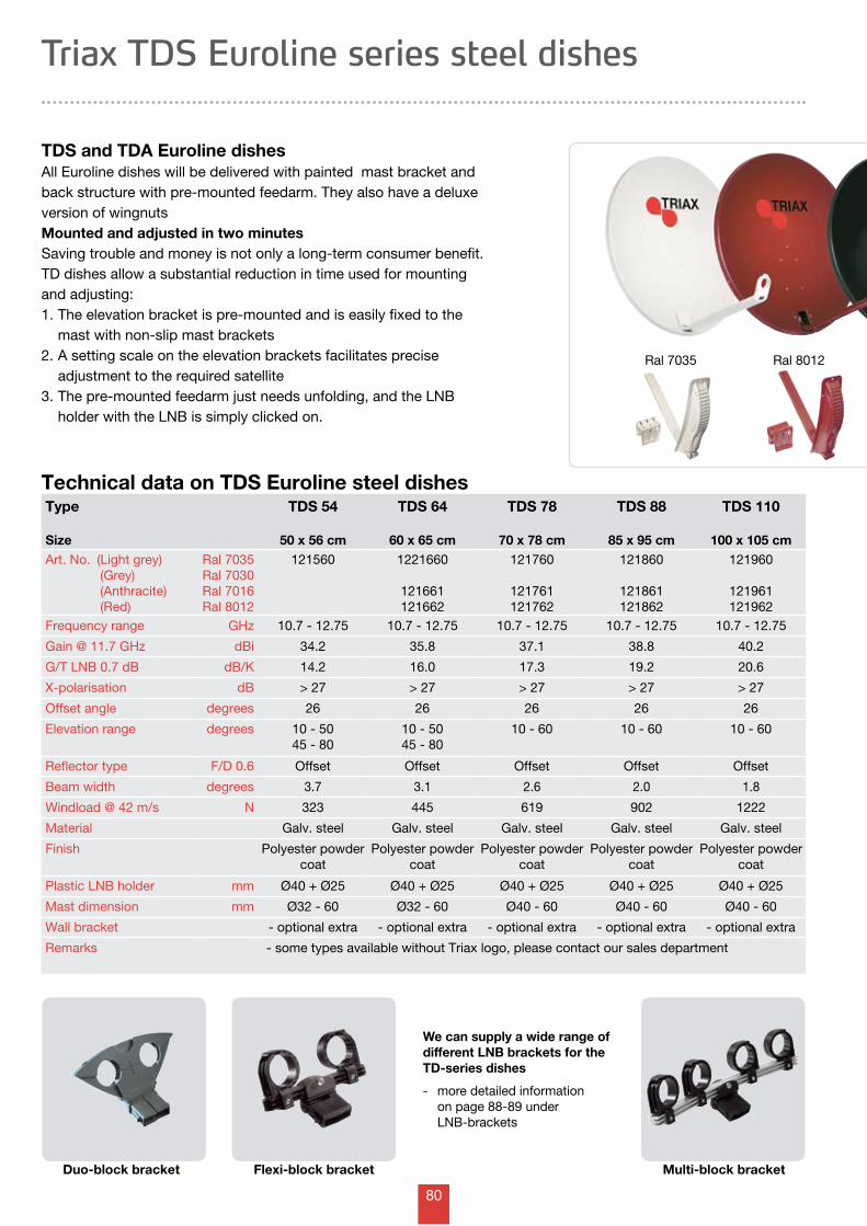
80
Technical data on TDS Euroline steel dishesType
Size
TDS 54
50 x 56 cm
TDS 64
60 x 65 cm
TDS 78
70 x 78 cm
TDS 88
85 x 95 cm
TDS 110
100 x 105 cmArt. No. (Light grey) (Grey) (Anthracite) (Red)
Ral 7035Ral 7030Ral 7016Ral 8012
121560 1221660
121661121662
121760
121761121762
121860
121861121862
121960
121961121962
Frequency range GHz 10.7 - 12.75 10.7 - 12.75 10.7 - 12.75 10.7 - 12.75 10.7 - 12.75
Gain @ 11.7 GHz dBi 34.2 35.8 37.1 38.8 40.2
G/T LNB 0.7 dB dB/K 14.2 16.0 17.3 19.2 20.6
X-polarisation dB > 27 > 27 > 27 > 27 > 27
Offset angle degrees 26 26 26 26 26
Elevation range degrees 10 - 5045 - 80
10 - 5045 - 80
10 - 60 10 - 60 10 - 60
Reflector type F/D 0.6 Offset Offset Offset Offset Offset
Beam width degrees 3.7 3.1 2.6 2.0 1.8
Windload @ 42 m/s N 323 445 619 902 1222
Material Galv. steel Galv. steel Galv. steel Galv. steel Galv. steel
Finish Polyester powdercoat
Polyester powdercoat
Polyester powdercoat
Polyester powdercoat
Polyester powdercoat
Plastic LNB holder mm Ø40 + Ø25 Ø40 + Ø25 Ø40 + Ø25 Ø40 + Ø25 Ø40 + Ø25
Mast dimension mm Ø32 - 60 Ø32 - 60 Ø40 - 60 Ø40 - 60 Ø40 - 60
Wall bracket - optional extra - optional extra - optional extra - optional extra - optional extra
Remarks - some types available without Triax logo, please contact our sales department
Triax TDS Euroline series steel dishes
TDS and TDA Euroline dishesAll Euroline dishes will be delivered with painted mast bracket and back structure with pre-mounted feedarm. They also have a deluxe version of wingnutsMounted and adjusted in two minutesSaving trouble and money is not only a long-term consumer benefit. TD dishes allow a substantial reduction in time used for mounting and adjusting:1. The elevation bracket is pre-mounted and is easily fixed to the mast with non-slip mast brackets2. A setting scale on the elevation brackets facilitates precise adjustment to the required satellite 3. The pre-mounted feedarm just needs unfolding, and the LNB holder with the LNB is simply clicked on.
Ral 7035 Ral 8012
We can supply a wide range of different LNB brackets for the TD-series dishes
- more detailed information on page 88-89 under LNB-brackets
Duo-block bracket Flexi-block bracket Multi-block bracket
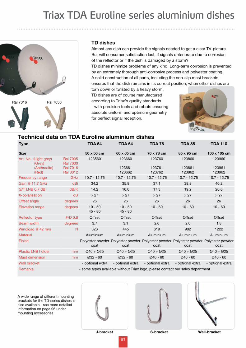
81
Triax TDA Euroline series aluminium dishes
Technical data on TDA Euroline aluminium dishesType
Size
TDA 54
50 x 56 cm
TDA 64
60 x 65 cm
TDA 78
70 x 78 cm
TDA 88
85 x 95 cm
TDA 110
100 x 105 cmArt. No. (Light grey) (Grey) (Anthracite) (Red)
Ral 7035Ral 7030Ral 7016Ral 8012
123560 123660
123661123662
123760
123761123762
123860
123861123862
123960
123961123962
Frequency range GHz 10.7 - 12.75 10.7 - 12.75 10.7 - 12.75 10.7 - 12.75 10.7 - 12.75
Gain @ 11.7 GHz dBi 34.2 35.8 37.1 38.8 40.2
G/T LNB 0.7 dB dB/K 14.2 16.0 17.3 19.2 20.6
X-polarisation dB > 27 > 27 > 27 > 27 > 27
Offset angle degrees 26 26 26 26 26
Elevation range degrees 10 - 5045 - 80
10 - 5045 - 80
10 - 60 10 - 60 10 - 60
Reflector type F/D 0.6 Offset Offset Offset Offset Offset
Beam width degrees 3.7 3.1 2.6 2.0 1.8
Windload @ 42 m/s N 323 445 619 902 1222
Material Aluminium Aluminium Aluminium Aluminium Aluminium
Finish Polyester powdercoat
Polyester powdercoat
Polyester powdercoat
Polyester powdercoat
Polyester powdercoat
Plastic LNB holder mm Ø40 + Ø25 Ø40 + Ø25 Ø40 + Ø25 Ø40 + Ø25 Ø40 + Ø25
Mast dimension mm Ø32 - 60 Ø32 - 60 Ø40 - 60 Ø40 - 60 Ø40 - 60
Wall bracket - optional extra - optional extra - optional extra - optional extra - optional extra
Remarks - some types available without Triax logo, please contact our sales department
TD dishesAlmost any dish can provide the signals needed to get a clear TV-picture. But will consumer satisfaction last, if signals deteriorate due to corrosion of the reflector or if the dish is damaged by a storm?TD dishes minimize problems of any kind. Long-term corrosion is prevented by an extremely thorough anti-corrosive process and polyester coating. A solid construction of all parts, including the non-slip mast brackets, ensures that the dish remains in its correct position, when other dishes are torn down or twisted by a heavy storm. TD dishes are of course manufactured according to Triax’s quality standards - with precision tools and robots ensuring absolute uniform and optimum geometry for perfect signal reception.
Ral 7016 Ral 7030
A wide range of different mountingbrackets for the TD-series dishes is also available - see more detailed information on page 96 under mounting accessories
J-bracket S-bracket Wall-bracket
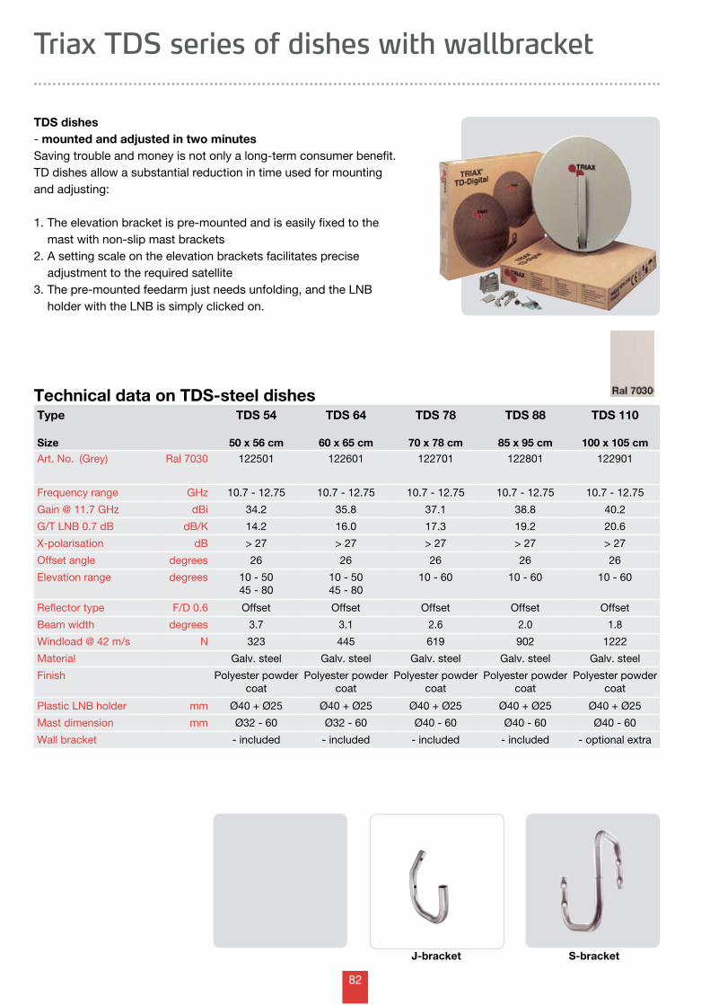
82
J-bracket S-bracket
Technical data on TDS-steel dishesType
Size
TDS 54
50 x 56 cm
TDS 64
60 x 65 cm
TDS 78
70 x 78 cm
TDS 88
85 x 95 cm
TDS 110
100 x 105 cmArt. No. (Grey) Ral 7030 122501 122601 122701 122801 122901
Frequency range GHz 10.7 - 12.75 10.7 - 12.75 10.7 - 12.75 10.7 - 12.75 10.7 - 12.75
Gain @ 11.7 GHz dBi 34.2 35.8 37.1 38.8 40.2
G/T LNB 0.7 dB dB/K 14.2 16.0 17.3 19.2 20.6
X-polarisation dB > 27 > 27 > 27 > 27 > 27
Offset angle degrees 26 26 26 26 26
Elevation range degrees 10 - 5045 - 80
10 - 5045 - 80
10 - 60 10 - 60 10 - 60
Reflector type F/D 0.6 Offset Offset Offset Offset Offset
Beam width degrees 3.7 3.1 2.6 2.0 1.8
Windload @ 42 m/s N 323 445 619 902 1222
Material Galv. steel Galv. steel Galv. steel Galv. steel Galv. steel
Finish Polyester powdercoat
Polyester powdercoat
Polyester powdercoat
Polyester powdercoat
Polyester powdercoat
Plastic LNB holder mm Ø40 + Ø25 Ø40 + Ø25 Ø40 + Ø25 Ø40 + Ø25 Ø40 + Ø25
Mast dimension mm Ø32 - 60 Ø32 - 60 Ø40 - 60 Ø40 - 60 Ø40 - 60
Wall bracket - included - included - included - included - optional extra
Triax TDS series of dishes with wallbracket
TDS dishes- mounted and adjusted in two minutesSaving trouble and money is not only a long-term consumer benefit. TD dishes allow a substantial reduction in time used for mounting and adjusting:
1. The elevation bracket is pre-mounted and is easily fixed to the mast with non-slip mast brackets2. A setting scale on the elevation brackets facilitates precise adjustment to the required satellite 3. The pre-mounted feedarm just needs unfolding, and the LNB holder with the LNB is simply clicked on.
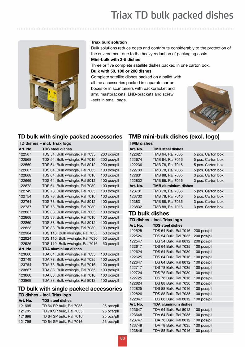
83
Triax TD bulk packed dishes
Triax bulk solutionBulk solutions reduce costs and contribute considerably to the protection of the environment due to the heavy reduction of packaging costs.Mini-bulk with 3-5 dishesThree or five complete satellite dishes packed in one carton box.Bulk with 50, 100 or 200 dishesComplete satellite dishes packed on a pallet with all the accessories packed in separate carton boxes or in scantainers with backbracket and arm, mastbrackets, LNB-brackets and screw-sets in small bags.
TD bulk dishesTD dishes - incl. Triax logoArt. No. TDS steel dishes122525 TDS 54 Bulk, Ral 7016 200 pcs/pll122526 TDS 54 Bulk, Ral 7035 200 pcs/pll122547 TDS 54 Bulk, Ral 8012 200 pcs/pll122617 TDS 64 Bulk, Ral 7035 100 pcs/pll122624 TDS 64 Bulk, Ral 7030 100 pcs/pll122625 TDS 64 Bulk, Ral 7016 100 pcs/pll122647 TDS 64 Bulk, Ral 8012 100 pcs/pll122717 TDS 78 Bulk, Ral 7035 100 pcs/pll122724 TDS 78 Bulk, Ral 7030 100 pcs/pll122725 TDS 78 Bulk, Ral 7016 100 pcs/pll122824 TDS 88 Bulk, Ral 7030 100 pcs/pll122825 TDS 88 Bulk, Ral 7016 100 pcs/pll122826 TDS 88 Bulk, Ral 7035 100 pcs/pll122847 TDS 88 Bulk, Ral 8012 100 pcs/pllArt. No. TDA aluminium dishes123647 TDA 64 Bulk, Ral 8012 100 pcs/pll123648 TDA 64 Bulk, Ral 7035 100 pcs/pll123747 TDA 78 Bulk, Ral 8012 100 pcs/pll123748 TDA 78 Bulk, Ral 7035 100 pcs/pll123846 TDA 88 Bulk, Ral 7016 100 pcs/pll
TMB mini-bulk dishes (excl. logo)TMB dishesArt. No. TMB steel dishes122627 TMB 64, Ral 7035 5 pcs. Carton box122674 TMB 64, Ral 7016 5 pcs. Carton box122236 TMB 78, Ral 7016 5 pcs. Carton box122733 TMB 78, Ral 7035 5 pcs. Carton box122831 TMB 88, Ral 7035 3 pcs. Carton box122832 TMB 88, Ral 7016 3 pcs. Carton boxArt. No. TMB aluminium dishes123731 TMB 78, Ral 7035 5 pcs. Carton box123732 TMB 78, Ral 7016 5 pcs. Carton box123831 TMB 88, Ral 7035 3 pcs. Carton box123832 TMB 88, Ral 7016 3 pcs. Carton box
TD bulk with single packed accessoriesTD dishes - incl. Triax logoArt. No. TDS steel dishes122567 TDS 54, Bulk w/single, Ral 7035 200 pcs/pll122568 TDS 54, Bulk w/single, Ral 7016 200 pcs/pll122569 TDS 54, Bulk w/single, Ral 8012 200 pcs/pll122667 TDS 64, Bulk w/single, Ral 7035 100 pcs/pll122668 TDS 64, Bulk w/single, Ral 7016 100 pcs/pll122669 TDS 64, Bulk w/single, Ral 8012 100 pcs/pll122672 TDS 64, Bulk w/single, Ral 7030 100 pcs/pll122749 TDS 78, Bulk w/single, Ral 7035 100 pcs/pll122754 TDS 78, Bulk w/single, Ral 7016 100 pcs/pll122764 TDS 78, Bulk w/single, Ral 8012 100 pcs/pll122737 TDS 78, Bulk w/single, Ral 7030 100 pcs/pll122867 TDS 88, Bulk w/single, Ral 7035 100 pcs/pll122868 TDS 88, Bulk w/single, Ral 7016 100 pcs/pll122869 TDS 88, Bulk w/single, Ral 8012 100 pcs/pll122823 TDS 88, Bulk w/single, Ral 7030 100 pcs/pll122904 TDS 110, Bulk w/single, Ral 7035 50 pcs/pll122924 TDS 110, Bulk w/single, Ral 7030 50 pcs/pll122926 TDS 110, Bulk w/single, Ral 7016 50 pcs/pllArt. No. TDA aluminium dishes123666 TDA 64, Bulk w/single, Ral 7035 100 pcs/pll123749 TDA 78, Bulk w/single, Ral 7035 100 pcs/pll123754 TDA 78, Bulk w/single, Ral 7016 100 pcs/pll123867 TDA 88, Bulk w/single, Ral 7035 100 pcs/pll123868 TDA 88, Bulk w/single, Ral 7016 100 pcs/pll123869 TDA 88, Bulk w/single, Ral 8012 100 pcs/pll
TD bulk with single packed accessoriesTD dishes - incl. Triax logoArt. No. TDS steel dishes121695 TD 64 SP bulk, Ral 7035 25 pcs/pll121795 TD 78 SP bulk, Ral 7035 25 pcs/pll121696 TD 64 SP bulk, Ral 7016 25 pcs/pll121796 TD 64 SP bulk, Ral 7016 25 pcs/pll
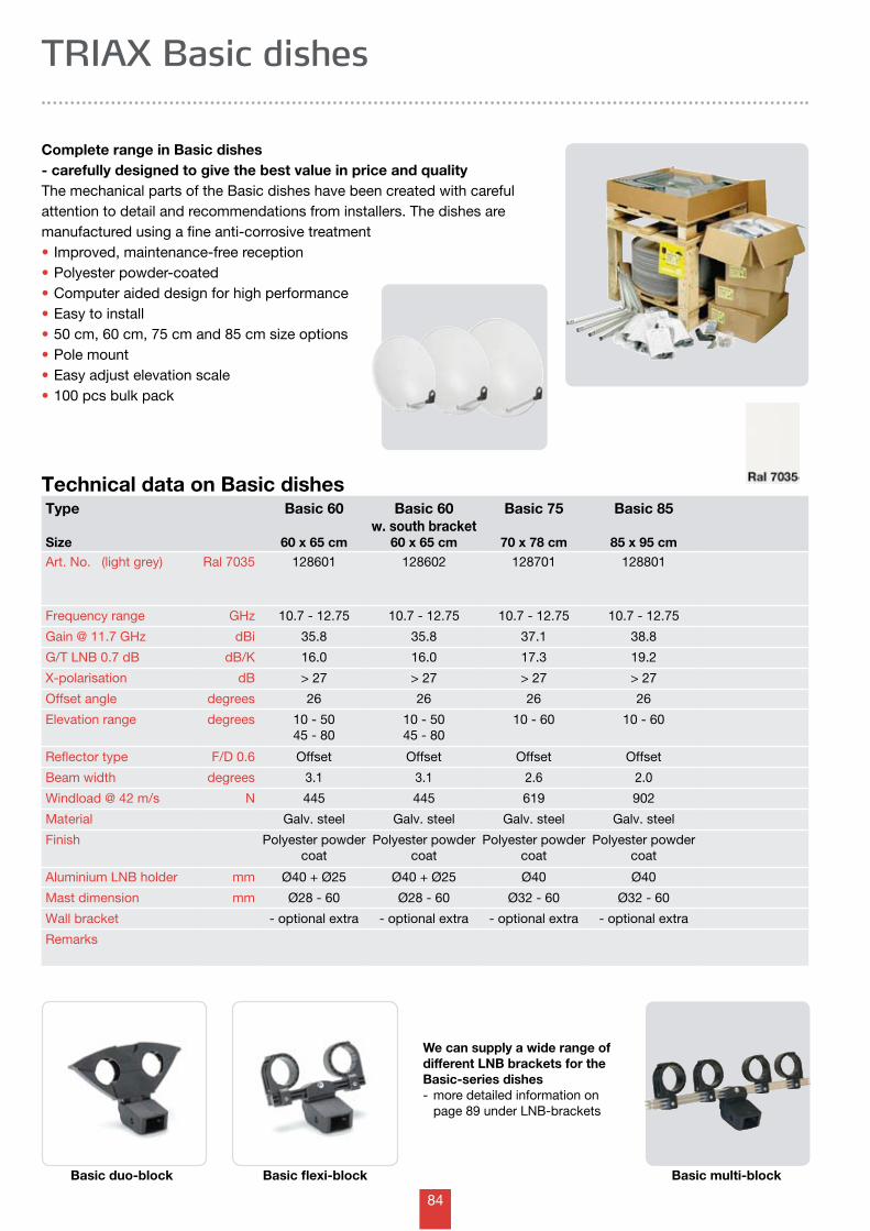
84
Technical data on Basic dishesType
Size
Basic 60
60 x 65 cm
Basic 60w. south bracket
60 x 65 cm
Basic 75
70 x 78 cm
Basic 85
85 x 95 cmArt. No. (light grey) Ral 7035 128601 128602 128701 128801
Frequency range GHz 10.7 - 12.75 10.7 - 12.75 10.7 - 12.75 10.7 - 12.75
Gain @ 11.7 GHz dBi 35.8 35.8 37.1 38.8
G/T LNB 0.7 dB dB/K 16.0 16.0 17.3 19.2
X-polarisation dB > 27 > 27 > 27 > 27
Offset angle degrees 26 26 26 26
Elevation range degrees 10 - 5045 - 80
10 - 5045 - 80
10 - 60 10 - 60
Reflector type F/D 0.6 Offset Offset Offset Offset
Beam width degrees 3.1 3.1 2.6 2.0
Windload @ 42 m/s N 445 445 619 902
Material Galv. steel Galv. steel Galv. steel Galv. steel
Finish Polyester powdercoat
Polyester powdercoat
Polyester powdercoat
Polyester powdercoat
Aluminium LNB holder mm Ø40 + Ø25 Ø40 + Ø25 Ø40 Ø40
Mast dimension mm Ø28 - 60 Ø28 - 60 Ø32 - 60 Ø32 - 60
Wall bracket - optional extra - optional extra - optional extra - optional extra
Remarks
TRIAX Basic dishes
Complete range in Basic dishes- carefully designed to give the best value in price and qualityThe mechanical parts of the Basic dishes have been created with careful attention to detail and recommendations from installers. The dishes are manufactured using a fine anti-corrosive treatment• Improved, maintenance-free reception• Polyester powder-coated• Computer aided design for high performance• Easy to install• 50 cm, 60 cm, 75 cm and 85 cm size options• Pole mount• Easy adjust elevation scale• 100 pcs bulk pack
Basic duo-block Basic flexi-block Basic multi-block
We can supply a wide range of different LNB brackets for the Basic-series dishes- more detailed information on page 89 under LNB-brackets
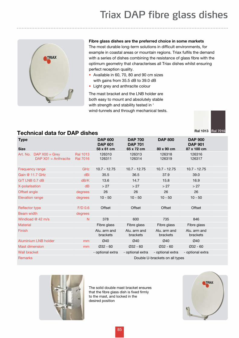
85
Triax DAP fibre glass dishes
Technical data for DAP dishesType
Size
DAP 600DAP 601
58 x 61 cm
DAP 700DAP 701
65 x 72 cm
DAP 800
80 x 90 cm
DAP 900DAP 901
87 x 100 cmArt. No. DAP X00 = Grey DAP X01 = Anthracite
Ral 1013Ral 7016
126310126311
126313126314
126318126319
126316126317
Frequency range GHz 10.7 - 12.75 10.7 - 12.75 10.7 - 12.75 10.7 - 12.75
Gain @ 11.7 GHz dBi 35.5 36.5 37.9 39.0
G/T LNB 0.7 dB dB/K 13.6 14.7 15.8 16.9
X-polarisation dB > 27 > 27 > 27 > 27
Offset angle degrees 26 26 26 26
Elevation range degrees 10 - 50 10 - 50 10 - 50 10 - 50
Reflector type F/D 0.6 Offset Offset Offset Offset
Beam width degrees
Windload @ 42 m/s N 378 600 735 846
Material Fibre glass Fibre glass Fibre glass Fibre glass
Finish Alu. arm andbrackets
Alu. arm andbrackets
Alu. arm andbrackets
Alu. arm andbrackets
Aluminium LNB holder mm Ø40 Ø40 Ø40 Ø40
Mast dimension mm Ø32 - 60 Ø32 - 60 Ø32 - 60 Ø32 - 60
Wall bracket - optional extra - optional extra - optional extra - optional extra
Remarks Double U-brackets on all types
Fibre glass dishes are the preferred choice in some marketsThe most durable long-term solutions in difficult environments, for example in coastal areas or mountain regions. Triax fulfils the demandwith a series of dishes combining the resistance of glass fibre with the optimum geometry that characterises all Triax dishes whilst ensuring perfect reception quality. • Available in 60, 70, 80 and 90 cm sizes with gains from 35.5 dB to 39.0 dB• Light grey and anthracite colour
The mast bracket and the LNB holder are both easy to mount and absolutely stable with strength and stability tested in ‘wind-tunnels and through mechanical tests.
The solid double mast bracket ensures that the fibre glass dish is fixed firmly to the mast, and locked in the desired position
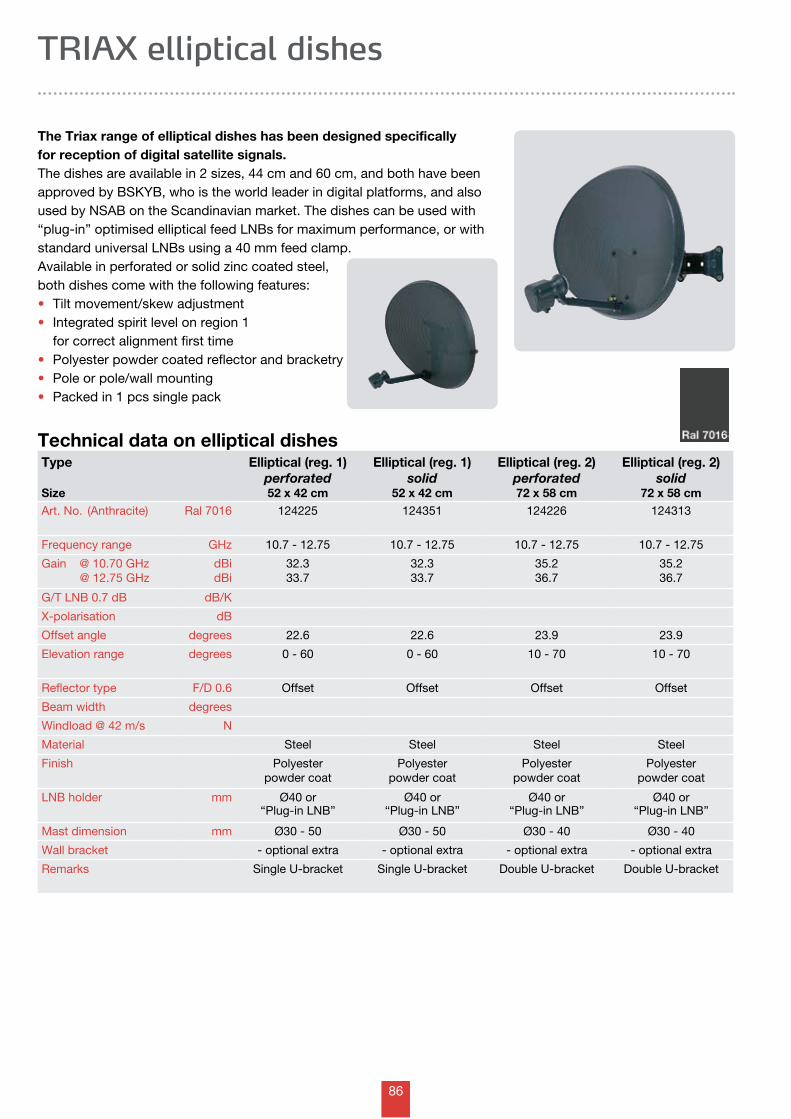
86
Technical data on elliptical dishesType
Size
Elliptical (reg. 1)perforated52 x 42 cm
Elliptical (reg. 1)solid
52 x 42 cm
Elliptical (reg. 2)perforated72 x 58 cm
Elliptical (reg. 2)solid
72 x 58 cmArt. No. (Anthracite) Ral 7016 124225 124351 124226 124313
Frequency range GHz 10.7 - 12.75 10.7 - 12.75 10.7 - 12.75 10.7 - 12.75
Gain @ 10.70 GHz @ 12.75 GHz
dBidBi
32.333.7
32.333.7
35.236.7
35.236.7
G/T LNB 0.7 dB dB/K
X-polarisation dB
Offset angle degrees 22.6 22.6 23.9 23.9
Elevation range degrees 0 - 60 0 - 60 10 - 70 10 - 70
Reflector type F/D 0.6 Offset Offset Offset Offset
Beam width degrees
Windload @ 42 m/s N
Material Steel Steel Steel Steel
Finish Polyester powder coat
Polyester powder coat
Polyester powder coat
Polyester powder coat
LNB holder mm Ø40 or “Plug-in LNB”
Ø40 or “Plug-in LNB”
Ø40 or “Plug-in LNB”
Ø40 or “Plug-in LNB”
Mast dimension mm Ø30 - 50 Ø30 - 50 Ø30 - 40 Ø30 - 40
Wall bracket - optional extra - optional extra - optional extra - optional extra
Remarks Single U-bracket Single U-bracket Double U-bracket Double U-bracket
TRIAX elliptical dishes
The Triax range of elliptical dishes has been designed specifically for reception of digital satellite signals.The dishes are available in 2 sizes, 44 cm and 60 cm, and both have been approved by BSKYB, who is the world leader in digital platforms, and also used by NSAB on the Scandinavian market. The dishes can be used with “plug-in” optimised elliptical feed LNBs for maximum performance, or with standard universal LNBs using a 40 mm feed clamp.Available in perforated or solid zinc coated steel, both dishes come with the following features:• Tilt movement/skew adjustment• Integrated spirit level on region 1 for correct alignment first time• Polyester powder coated reflector and bracketry• Pole or pole/wall mounting• Packed in 1 pcs single pack
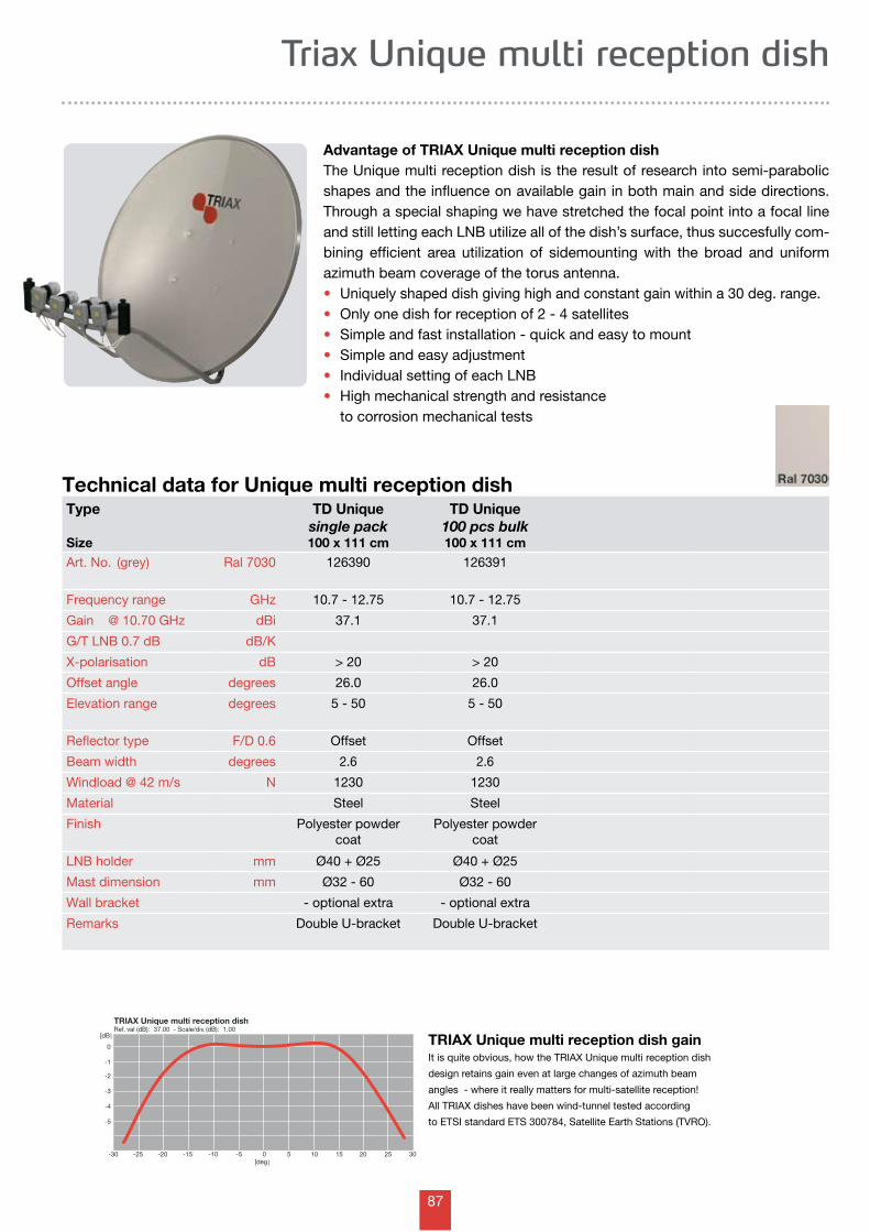
87
-30 -25 -20 -15 -10 -5 0 5 10 15 20 25 30
TRIAX Unique multi reception dishRef. val (dB): 37.00 - Scale/div. (dB): 1.00
0
-1
-2
-3
-4
-5
[dB]
[deg ]
Triax Unique multi reception dish
Technical data for Unique multi reception dish
Advantage of TRIAX Unique multi reception dishThe Unique multi reception dish is the result of research into semi-parabolic shapes and the influence on available gain in both main and side directions. Through a special shaping we have stretched the focal point into a focal line and still letting each LNB utilize all of the dish’s surface, thus succesfully com-bining efficient area utilization of sidemounting with the broad and uniform azimuth beam coverage of the torus antenna.• Uniquely shaped dish giving high and constant gain within a 30 deg. range.• Only one dish for reception of 2 - 4 satellites• Simple and fast installation - quick and easy to mount• Simple and easy adjustment• Individual setting of each LNB• High mechanical strength and resistance to corrosion mechanical tests
TRIAX Unique multi reception dish gainIt is quite obvious, how the TRIAX Unique multi reception dish
design retains gain even at large changes of azimuth beam
angles - where it really matters for multi-satellite reception!
All TRIAX dishes have been wind-tunnel tested according
to ETSI standard ETS 300784, Satellite Earth Stations (TVRO).
Type
Size
TD Uniquesingle pack100 x 111 cm
TD Unique100 pcs bulk100 x 111 cm
Art. No. (grey) Ral 7030 126390 126391
Frequency range GHz 10.7 - 12.75 10.7 - 12.75
Gain @ 10.70 GHz dBi 37.1 37.1
G/T LNB 0.7 dB dB/K
X-polarisation dB > 20 > 20
Offset angle degrees 26.0 26.0
Elevation range degrees 5 - 50 5 - 50
Reflector type F/D 0.6 Offset Offset
Beam width degrees 2.6 2.6
Windload @ 42 m/s N 1230 1230
Material Steel Steel
Finish Polyester powdercoat
Polyester powdercoat
LNB holder mm Ø40 + Ø25 Ø40 + Ø25
Mast dimension mm Ø32 - 60 Ø32 - 60
Wall bracket - optional extra - optional extra
Remarks Double U-bracket Double U-bracket
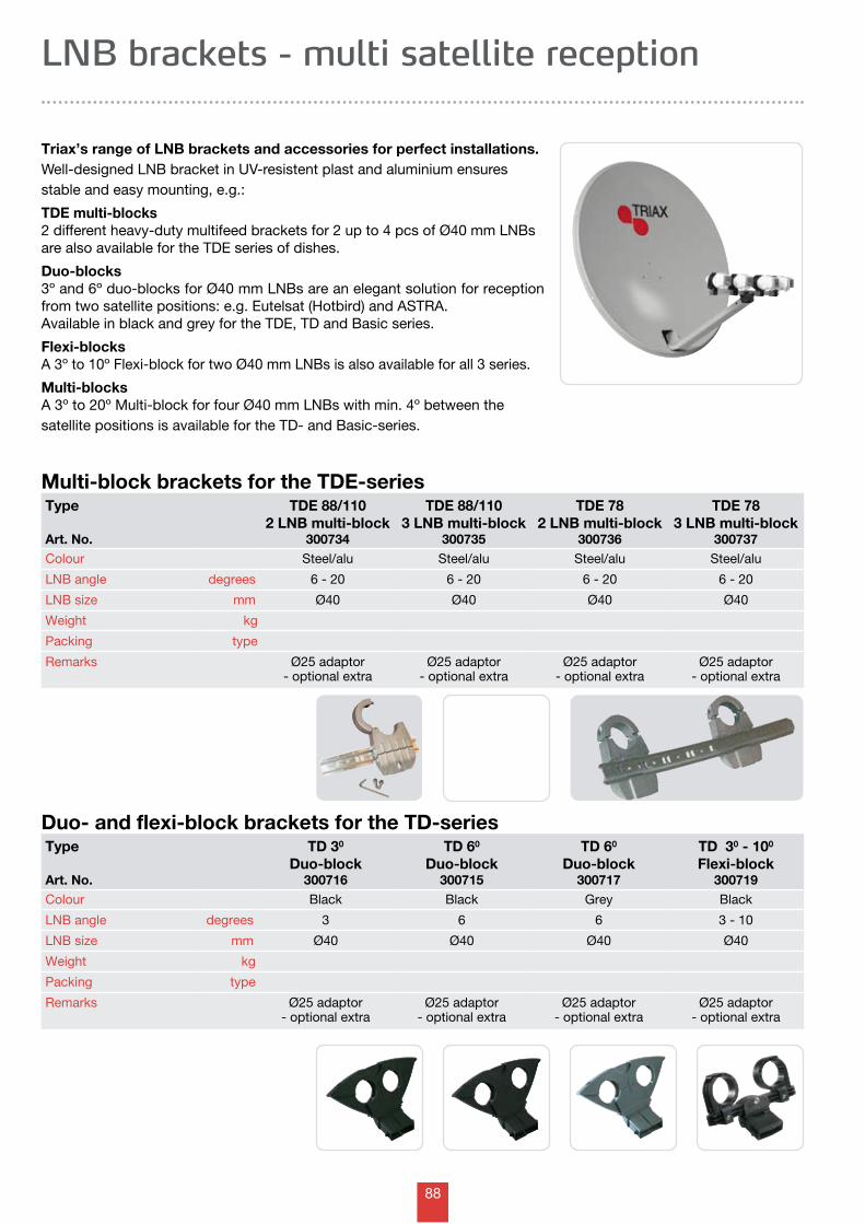
88
LNB brackets - multi satellite reception
Triax’s range of LNB brackets and accessories for perfect installations.Well-designed LNB bracket in UV-resistent plast and aluminium ensures stable and easy mounting, e.g.:
TDE multi-blocks2 different heavy-duty multifeed brackets for 2 up to 4 pcs of Ø40 mm LNBs are also available for the TDE series of dishes.
Duo-blocks3º and 6º duo-blocks for Ø40 mm LNBs are an elegant solution for reception from two satellite positions: e.g. Eutelsat (Hotbird) and ASTRA. Available in black and grey for the TDE, TD and Basic series.
Flexi-blocksA 3º to 10º Flexi-block for two Ø40 mm LNBs is also available for all 3 series.
Multi-blocksA 3º to 20º Multi-block for four Ø40 mm LNBs with min. 4º between the satellite positions is available for the TD- and Basic-series.
Duo- and flexi-block brackets for the TD-seriesType
Art. No.
TD 30
Duo-block300716
TD 60
Duo-block300715
TD 60
Duo-block300717
TD 30 - 100
Flexi-block300719
Colour Black Black Grey Black
LNB angle degrees 3 6 6 3 - 10
LNB size mm Ø40 Ø40 Ø40 Ø40
Weight kg
Packing type
Remarks Ø25 adaptor- optional extra
Ø25 adaptor- optional extra
Ø25 adaptor- optional extra
Ø25 adaptor- optional extra
Multi-block brackets for the TDE-seriesType
Art. No.
TDE 88/110 2 LNB multi-block
300734
TDE 88/110 3 LNB multi-block
300735
TDE 78 2 LNB multi-block
300736
TDE 783 LNB multi-block
300737Colour Steel/alu Steel/alu Steel/alu Steel/alu
LNB angle degrees 6 - 20 6 - 20 6 - 20 6 - 20
LNB size mm Ø40 Ø40 Ø40 Ø40
Weight kg
Packing type
Remarks Ø25 adaptor- optional extra
Ø25 adaptor- optional extra
Ø25 adaptor- optional extra
Ø25 adaptor- optional extra
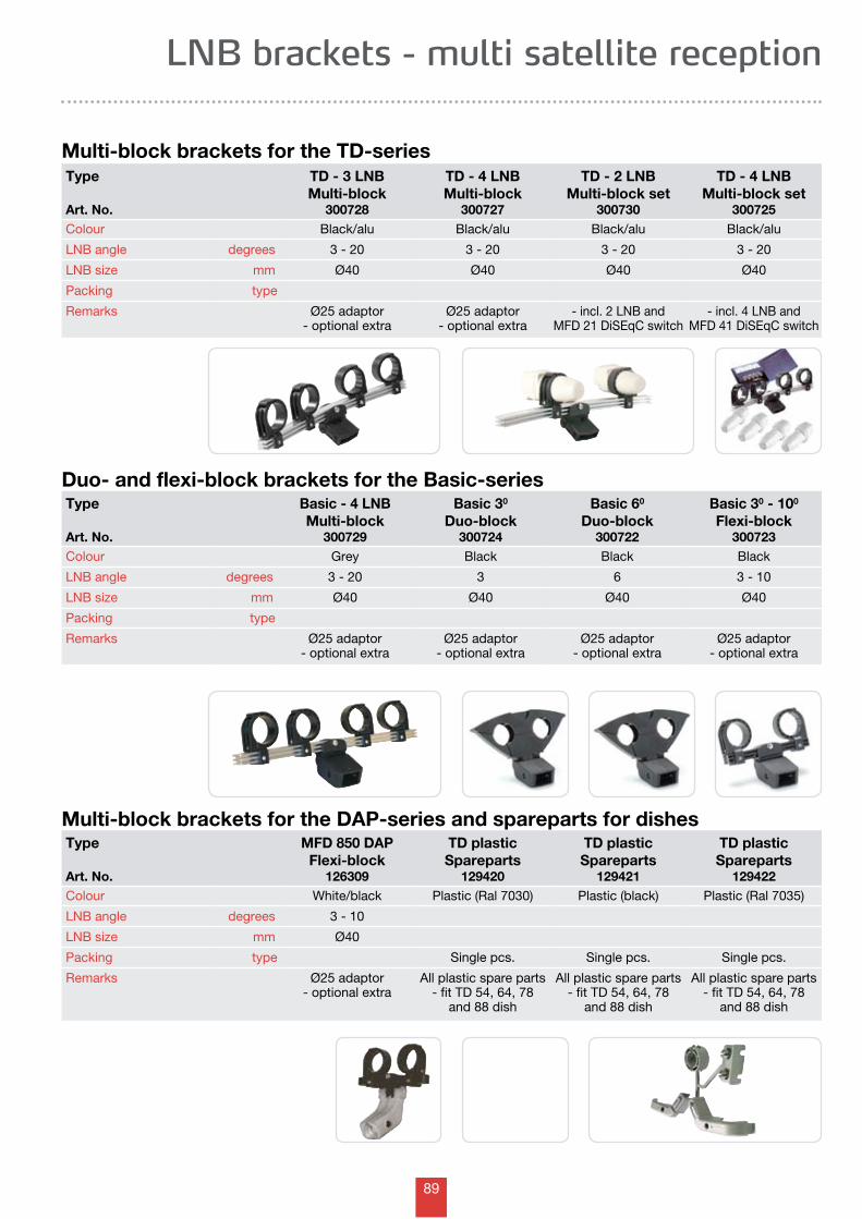
89
Type
Art. No.
Basic - 4 LNBMulti-block
300729
Basic 30
Duo-block300724
Basic 60
Duo-block300722
Basic 30 - 100
Flexi-block300723
Colour Grey Black Black Black
LNB angle degrees 3 - 20 3 6 3 - 10
LNB size mm Ø40 Ø40 Ø40 Ø40
Packing type
Remarks Ø25 adaptor- optional extra
Ø25 adaptor- optional extra
Ø25 adaptor- optional extra
Ø25 adaptor- optional extra
Type
Art. No.
MFD 850 DAPFlexi-block
126309
TD plastic Spareparts
129420
TD plastic Spareparts
129421
TD plastic Spareparts
129422Colour White/black Plastic (Ral 7030) Plastic (black) Plastic (Ral 7035)
LNB angle degrees 3 - 10
LNB size mm Ø40
Packing type Single pcs. Single pcs. Single pcs.
Remarks Ø25 adaptor- optional extra
All plastic spare parts - fit TD 54, 64, 78
and 88 dish
All plastic spare parts - fit TD 54, 64, 78
and 88 dish
All plastic spare parts - fit TD 54, 64, 78
and 88 dish
Multi-block brackets for the TD-seriesType
Art. No.
TD - 3 LNBMulti-block
300728
TD - 4 LNBMulti-block
300727
TD - 2 LNBMulti-block set
300730
TD - 4 LNBMulti-block set
300725Colour Black/alu Black/alu Black/alu Black/alu
LNB angle degrees 3 - 20 3 - 20 3 - 20 3 - 20
LNB size mm Ø40 Ø40 Ø40 Ø40
Packing type
Remarks Ø25 adaptor- optional extra
Ø25 adaptor- optional extra
- incl. 2 LNB and MFD 21 DiSEqC switch
- incl. 4 LNB and MFD 41 DiSEqC switch
LNB brackets - multi satellite reception
Multi-block brackets for the DAP-series and spareparts for dishes
Duo- and flexi-block brackets for the Basic-series
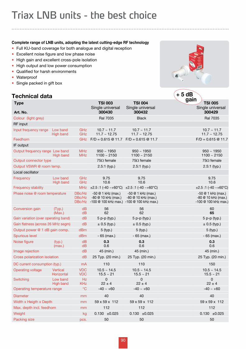
90
Technical dataType
Art. No.
TSI 003Single universal
300430
TSI 004Single universal
300432
TSI 005Single universal
300429Colour (light grey) Ral 7035 Black Ral 7035
RF input
Input frequency range Low band High band
GHzGHz
10.7 ~ 11.711.7 ~ 12.75
10.7 ~ 11.711.7 ~ 12.75
10.7 ~ 11.711.7 ~ 12.75
Feedhorn GHz F/D = 0.615 @ 11.7 F/D = 0.615 @ 11.7 F/D = 0.615 @ 11.7
IF output
Output frequency range Low band High band
MHzMHz
950 ~ 19501100 ~ 2150
950 ~ 19501100 ~ 2150
950 ~ 19501100 ~ 2150
Output connector type 75W female 75W female 75W female
Output VSWR @ room temp. 2.5:1 (typ.) 2.5:1 (typ.) 2.5:1 (typ.)
Local oscillator
Frequency Low band High band
GHzGHz
9.7510.6
9.7510.6
9.7510.6
Frequency stability MHz ±2.5 :1 (-40 ~+60°C) ±2.5 :1 (-40 ~+60°C) ±2.5 :1 (-40 ~+60°C)
Phase noise @ room temperature DBc/HzDBc/HzDBc/Hz
-50 @ 1 kHz (max.)-80 @ 10 kHz (max.)
-100 @ 100 kHz max.)
-50 @ 1 kHz (max.)-80 @ 10 kHz (max.)
-100 @ 100 kHz max.)
-50 @ 1 kHz (max.)-80 @ 10 kHz (max.)
-100 @ 100 kHz max.)
Conversion gain (Typ.) (Max.)
dBdB
5662
5662
6065
Gain variation (over operating band) dB 5 p-p (typ.) 5 p-p (typ.) 5 p-p (typ.)
Gain flatness (across 26 MHz segm) dB ± 0.5 (typ.) ± 0.5 (typ.) ± 0.5 (typ.)
Output power @ 1 dB gain comp. dBm 5 (typ.) 5 (typ.) 5 (typ.)
Spurious level dBm - 65 (max.) - 65 (max.) - 65 (max.)
Noise figure (typ.) (max.)
dBdB
0.30.6
0.30.6
0.30.6
Image rejection dB 45 (min.) 45 (min.) 45 (min.)
Cross polarization isolation dB 25 Typ. (20 min.) 25 Typ. (20 min.) 25 Typ. (20 min.)
DC current consumption (typ.) mA 110 110 150
Operating voltage Vertical Horizontal
VDCVDC
10.5 ~ 14.515.5 ~ 21
10.5 ~ 14.515.5 ~ 21
10.5 ~ 14.515.5 ~ 21
Switching Low band High band
HzKHz
022 ± 4
022 ± 4
022 ± 4
Operating temperature range °C -40 ~ +60 -40 ~ +60 -40 ~ +60
Diameter mm 40 40 40
Width x Heigth x Depth mm 59 x 59 x 112 59 x 59 x 112 59 x 59 x 112
Max. depth incl. feedhorn mm 112 112 112
Weight kg 0.130 ±0.025 0.130 ±0.025 0.130 ±0.025
Packing size pcs. 50 50 50
+ 5 dB gain
Triax LNB units - the best choice
Complete range of LNB units, adopting the latest cutting-edge RF technology• Full KU-band coverage for both analogue and digital reception • Excellent noise figure and low phase noise• High gain and excellent cross-pole isolation • High output and low power consumption • Qualified for harsh environments • Waterproof• Single packed in gift box
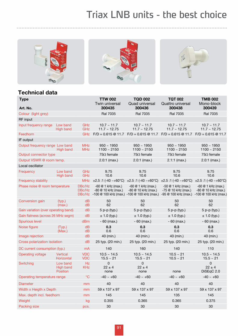
91
Triax LNB units - the best choice
Technical dataType
Art. No.
TTW 002 Twin universal
300435
TQD 002 Quad universal
300436
TQT 002 Quattro universal
300438
TMB 002 Mono-block
300439Colour (light grey) Ral 7035 Ral 7035 Ral 7035 Ral 7035
RF input
Input frequency range Low band High band
GHzGHz
10.7 ~ 11.711.7 ~ 12.75
10.7 ~ 11.711.7 ~ 12.75
10.7 ~ 11.711.7 ~ 12.75
10.7 ~ 11.711.7 ~ 12.75
Feedhorn GHz F/D = 0.615 @ 11.7 F/D = 0.615 @ 11.7 F/D = 0.615 @ 11.7 F/D = 0.615 @ 11.7
IF output
Output frequency range Low band High band
MHzMHz
950 ~ 19501100 ~ 2150
950 ~ 19501100 ~ 2150
950 ~ 19501100 ~ 2150
950 ~ 19501100 ~ 2150
Output connector type 75W female 75W female 75W female 75W female
Output VSWR @ room temp. 2.0:1 (max.) 2.0:1 (max.) 2.1:1 (max.) 2.0:1 (max.)
Local oscillator
Frequency Low band High band
GHzGHz
9.7510.6
9.7510.6
9.7510.6
9.7510.6
Frequency stability MHz ±2.5 :1 (-40 ~+60°C) ±2.5 :1 (-40 ~+60°C) ±2.5 :1 (-40 ~+60°C) ±2.5 :1 (-40 ~+60°C)
Phase noise @ room temperature DBc/HzDBc/HzDBc/Hz
-60 @ 1 kHz (max.)-80 @ 10 kHz (max.)
-100 @ 100 kHz (max.)
-60 @ 1 kHz (max.)-80 @ 10 kHz (max.)
-100 @ 100 kHz (max.)
-50 @ 1 kHz (max.)-75 @ 10 kHz (max.)
-95 @ 100 kHz (max.)
-60 @ 1 kHz (max.)-80 @ 10 kHz (max.)
-100 @ 100 kHz (max.)
Conversion gain (typ.) (max.)
dBdB
5062
5062
5062
5062
Gain variation (over operating band) dB 5 p-p (typ.) 5 p-p (typ.) 5 p-p (typ.) 5 p-p (typ.)
Gain flatness (across 26 MHz segm) dB ± 1.0 (typ.) ± 1.0 (typ.) ± 1.0 (typ.) ± 1.0 (typ.)
Spurious level dBm - 60 (max.) - 60 (max.) - 60 (max.) - 60 (max.)
Noise figure (Typ.) (Max.)
dBdB
0.30.6
0.30.6
0.30.6
0.30.6
Image rejection dB 40 (min.) 40 (min.) 40 (min.) 40 (min.)
Cross polarization isolation dB 25 typ. (20 min.) 25 typ. (20 min.) 25 typ. (20 min.) 25 typ. (20 min.)
DC current consumption (typ.) mA 140 160 140 110
Operating voltage Vertical Horizontal
VDCVDC
10.5 ~ 14.515.5 ~ 21
10.5 ~ 14.515.5 ~ 21
10.5 ~ 2110.5 ~ 21
10.5 ~ 14.515.5 ~ 21
Switching Low band High band Position
HzKHz
022 ± 4none
022 ± 4none none
022 ± 4
DiSEqC 2.0
Operating temperature range °C -40 ~ +60 -40 ~ +60 -40 ~ +60 -40 ~ +60
Diameter mm 40 40 40 40
Width x Heigth x Depth mm 59 x 137 x 97 59 x 137 x 97 59 x 137 x 97 59 x 137 x 97
Max. depth incl. feedhorn mm 145 145 135 145
Weight kg 0.355 0.365 0.365 0.375
Packing size pcs. 30 30 30 30
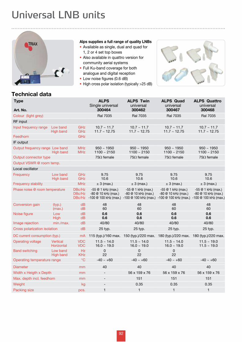
92
Universal LNB units
Technical data
Alps supplies a full range of quality LNBs• Available as single, dual and quad for 1, 2 or 4 set top boxes • Also available in quattro version for community aerial systems • Full Ku-band coverage for both analogue and digital reception • Low noise figures (0.6 dB) • High cross polar isolation (typically >25 dB)
Type
Art. No.
ALPSSingle universal
300464
ALPS Twin universal300462
ALPS Quad universal300467
ALPS Quattro universal300468
Colour (light grey) Ral 7035 Ral 7035 Ral 7035 Ral 7035
RF input
Input frequency range Low band High band
GHzGHz
10.7 ~ 11.711.7 ~ 12.75
10.7 ~ 11.711.7 ~ 12.75
10.7 ~ 11.711.7 ~ 12.75
10.7 ~ 11.711.7 ~ 12.75
Feedhorn GHz
IF output
Output frequency range Low band High band
MHzMHz
950 ~ 19501100 ~ 2150
950 ~ 19501100 ~ 2150
950 ~ 19501100 ~ 2150
950 ~ 19501100 ~ 2150
Output connector type 75W female 75W female 75W female 75W female
Output VSWR @ room temp.
Local oscillator
Frequency Low band High band
GHzGHz
9.7510.6
9.7510.6
9.7510.6
9.7510.6
Frequency stability MHz ± 3 (max.) ± 3 (max.) ± 3 (max.) ± 3 (max.)
Phase noise @ room temperature DBc/HzDBc/HzDBc/Hz
-55 @ 1 kHz (max.)-80 @ 10 kHz (max.)
-100 @ 100 kHz (max.)
-55 @ 1 kHz (max.)-80 @ 10 kHz (max.)
-100 @ 100 kHz (max.)
-55 @ 1 kHz (max.)-80 @ 10 kHz (max.)
-100 @ 100 kHz (max.)
-55 @ 1 kHz (max.)-80 @ 10 kHz (max.)
-100 @ 100 kHz (max.)
Conversion gain (typ.) (max.)
dBdB
4860
4860
4860
4860
Noise figure Low High
dBdB
0.60.6
0.60.6
0.60.6
0.60.6
Image rejection min./max. dB 40/80 40/80 40/80 40/80
Cross polarization isolation dB 25 typ. 25 typ. 25 typ. 25 typ.
DC current consumption (typ.) mA 115 (typ.)/160 max. 150 (typ.)/220 max. 180 (typ.)/220 max. 180 (typ.)/220 max.
Operating voltage Vertical Horizontal
VDCVDC
11.5 ~ 14.016.0 ~ 19.0
11.5 ~ 14.016.0 ~ 19.0
11.5 ~ 14.016.0 ~ 19.0
11.5 ~ 19.011.5 ~ 19.0
Band switching Low band High band
HzKHz
022
022
022
Operating temperature range °C -40 ~ +60 -40 ~ +60 -40 ~ +60 -40 ~ +60
Diameter mm 40 40 40 40
Width x Heigth x Depth mm - 56 x 159 x 76 56 x 159 x 76 56 x 159 x 76
Max. depth incl. feedhorn mm - 151 151 151
Weight kg - 0.35 0.35 0.35
Packing size pcs. 1 1 1 1
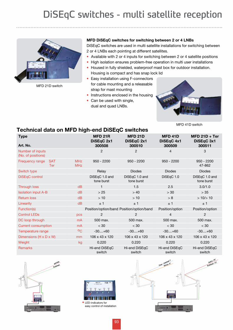
93
1 3
Eutelsat -13Astra -19
Sirius -5Thor - I
ntelsat 1
2 4
o
o
o
o
MFD 21D switch
MFD DiSEqC switches for switching between 2 or 4 LNBs DiSEqC switches are used in multi satellite installations for switching between 2 or 4 LNBs each pointing at different satellites. • Available with 2 or 4 inputs for switching between 2 or 4 satellite positions• High isolation ensures problem-free operation in multi user installations• Housed in fully shielded, waterproof mast box for outdoor installation.
Housing is compact and has snap lock lid• Easy installation using F-connectors for cable mounting and a releasable strap for mast mounting• Instructions enclosed in the housing• Can be used with single, dual and quad LNBs.
Type
Art. No.
MFD 21RDiSEqC 2x1
300508
MFD 21DDiSEqC 2x1
300510
MFD 41DDiSEqC 4x1
300509
MFD 21D + TerDiSEqC 3x1
300511Number of inputs (No. of positions)
2 2 4 3
Frequency range SAT Ter
MHzMHz
950 - 2200 950 - 2200 950 - 2200 950 - 220047-862
Switch type Relay Diodes Diodes Diodes
DiSEqC control DiSEqC 1.0 and tone burst
DiSEqC 1.0 and tone burst
DiSEqC 1.0 DiSEqC 1.0 and tone burst
Through loss dB 1 1.5 2.5 3.0/1.0
Isolation input A-B dB > 25 > 40 > 30 > 35
Return loss dB > 10 > 10 > 8 > 10/> 10
Linearity dB ± 1 ± 1 ± 1 ± 1
Function(s) Position/option/band Position/option/band Position/option Position/option
Control LEDs pcs 2 2 4 2
DC loop through mA 500 max. 500 max. 500 max. 500 max.
Current consumption mA < 30 < 30 < 30 < 30
Temperature range oC -30....+60 -30....+60 -30....+60 -30....+60
Dimensions (H x D x W) mm 106 x 43 x 120 106 x 43 x 120 106 x 43 x 120 106 x 43 x 120
Weight kg 0.220 0.220 0.220 0.220
Remarks Hi-end DiSEqCswitch
Hi-end DiSEqCswitch
Hi-end DiSEqCswitch
Hi-end DiSEqCswitch
Technical data on MFD high-end DiSEqC switches
DiSEqC switches - multi satellite reception
• LED-indicators for easy control of installation
MFD 41D switch
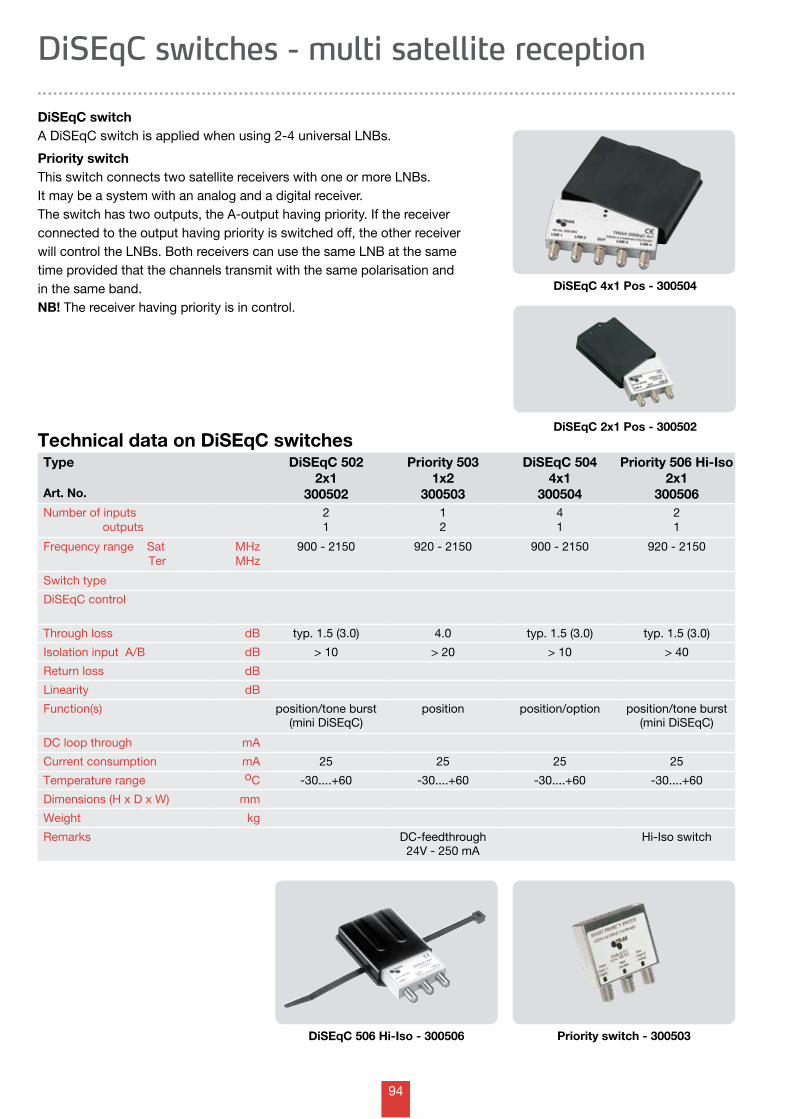
94
DiSEqC switches - multi satellite reception
Technical data on DiSEqC switches
DiSEqC switchA DiSEqC switch is applied when using 2-4 universal LNBs.
Priority switchThis switch connects two satellite receivers with one or more LNBs. It may be a system with an analog and a digital receiver. The switch has two outputs, the A-output having priority. If the receiver connected to the output having priority is switched off, the other receiver will control the LNBs. Both receivers can use the same LNB at the same time provided that the channels transmit with the same polarisation and in the same band. NB! The receiver having priority is in control.
Priority switch - 300503
DiSEqC 4x1 Pos - 300504
DiSEqC 2x1 Pos - 300502
Type
Art. No.
DiSEqC 5022x1
300502
Priority 5031x2
300503
DiSEqC 5044x1
300504
Priority 506 Hi-Iso2x1
300506Number of inputs outputs
21
12
41
21
Frequency range Sat Ter
MHzMHz
900 - 2150 920 - 2150 900 - 2150 920 - 2150
Switch type
DiSEqC control
Through loss dB typ. 1.5 (3.0) 4.0 typ. 1.5 (3.0) typ. 1.5 (3.0)
Isolation input A/B dB > 10 > 20 > 10 > 40
Return loss dB
Linearity dB
Function(s) position/tone burst(mini DiSEqC)
position position/option position/tone burst(mini DiSEqC)
DC loop through mA
Current consumption mA 25 25 25 25
Temperature range oC -30....+60 -30....+60 -30....+60 -30....+60
Dimensions (H x D x W) mm
Weight kg
Remarks DC-feedthrough24V - 250 mA
Hi-Iso switch
DiSEqC 506 Hi-Iso - 300506
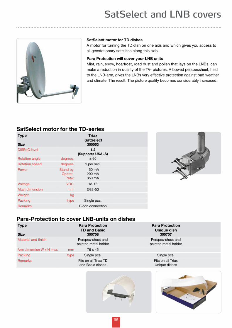
95
SatSelect and LNB covers
SatSelect motor for the TD-seriesType
Size
Triax SatSelect
300053DiSEqC level 1.2
(Supports USALS)Rotation angle degrees ± 60
Rotation speed degrees 1 per sec.
Power Stand byOperat.
Peak
50 mA200 mA350 mA
Voltage VDC 13-18
Mast dimension mm Ø32-50
Weight kg
Packing type Single pcs.
Remarks F-con connection
Para-Protection to cover LNB-units on dishesType
Size
Para ProtectionTD and Basic
300708
Para ProtectionUnique dish
300707Material and finish Perspex-sheet and
painted metal holderPerspex-sheet and
painted metal holder
Arm dimension W x H max. mm 76 x 45
Packing type Single pcs. Single pcs.
Remarks Fits on all Triax TD and Basic dishes
Fits on all TriaxUnique dishes
SatSelect motor for TD dishes A motor for turning the TD dish on one axis and which gives you access to all geostationary satellites along this axis.
Para Protection will cover your LNB units Mist, rain, snow, hoarfrost, road dust and pollen that lays on the LNBs, can make a reduction in quality of the TV- pictures. A bowed perspexsheet, held to the LNB-arm, gives the LNBs very effective protection against bad weather and climate. The result: The picture quality becomes considerably increased.
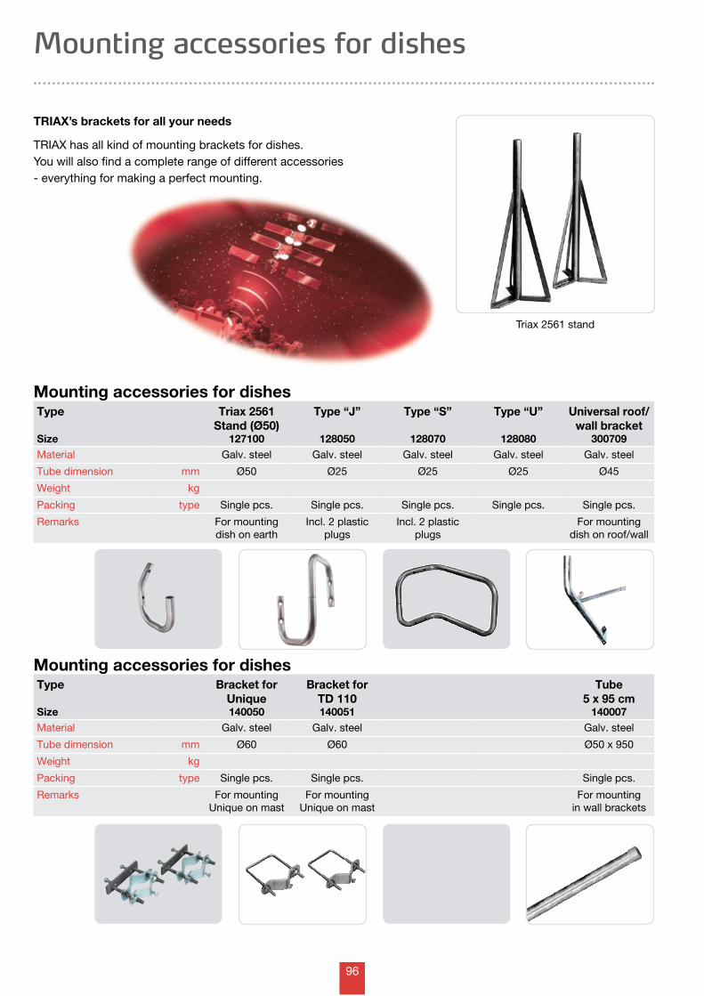
96
Mounting accessories for dishes
TRIAX’s brackets for all your needs
TRIAX has all kind of mounting brackets for dishes.You will also find a complete range of different accessories - everything for making a perfect mounting.
Mounting accessories for dishesType
Size
Triax 2561Stand (Ø50)
127100
Type “J”
128050
Type “S”
128070
Type “U”
128080
Universal roof/wall bracket
300709Material Galv. steel Galv. steel Galv. steel Galv. steel Galv. steel
Tube dimension mm Ø50 Ø25 Ø25 Ø25 Ø45
Weight kg
Packing type Single pcs. Single pcs. Single pcs. Single pcs. Single pcs.
Remarks For mounting dish on earth
Incl. 2 plastic plugs
Incl. 2 plastic plugs
For mounting dish on roof/wall
Mounting accessories for dishesType
Size
Bracket forUnique140050
Bracket forTD 110140051
Tube5 x 95 cm
140007Material Galv. steel Galv. steel Galv. steel
Tube dimension mm Ø60 Ø60 Ø50 x 950
Weight kg
Packing type Single pcs. Single pcs. Single pcs.
Remarks For mounting Unique on mast
For mounting Unique on mast
For mounting in wall brackets
Triax 2561 stand
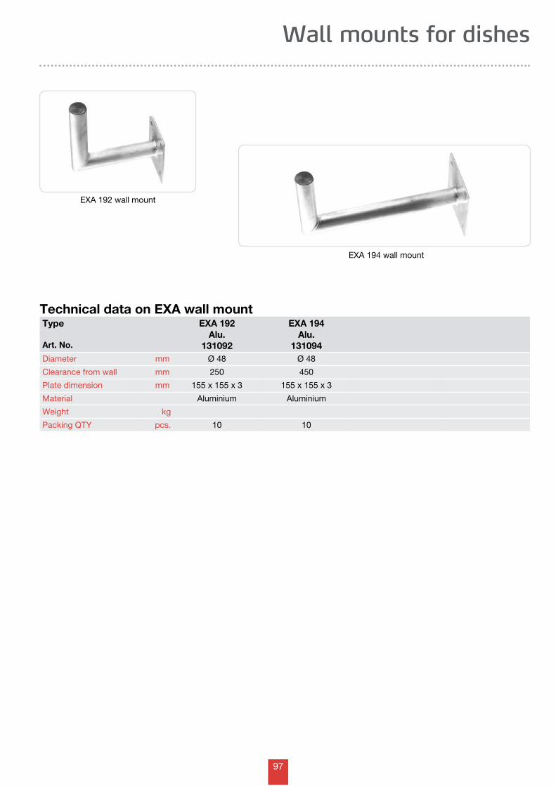
97
Technical data on EXA wall mount
EXA 192 wall mount
EXA 194 wall mount
Type
Art. No.
EXA 192Alu.
131092
EXA 194Alu.
131094Diameter mm Ø 48 Ø 48
Clearance from wall mm 250 450
Plate dimension mm 155 x 155 x 3 155 x 155 x 3
Material Aluminium Aluminium
Weight kg
Packing QTY pcs. 10 10
Wall mounts for dishes

98
Notes
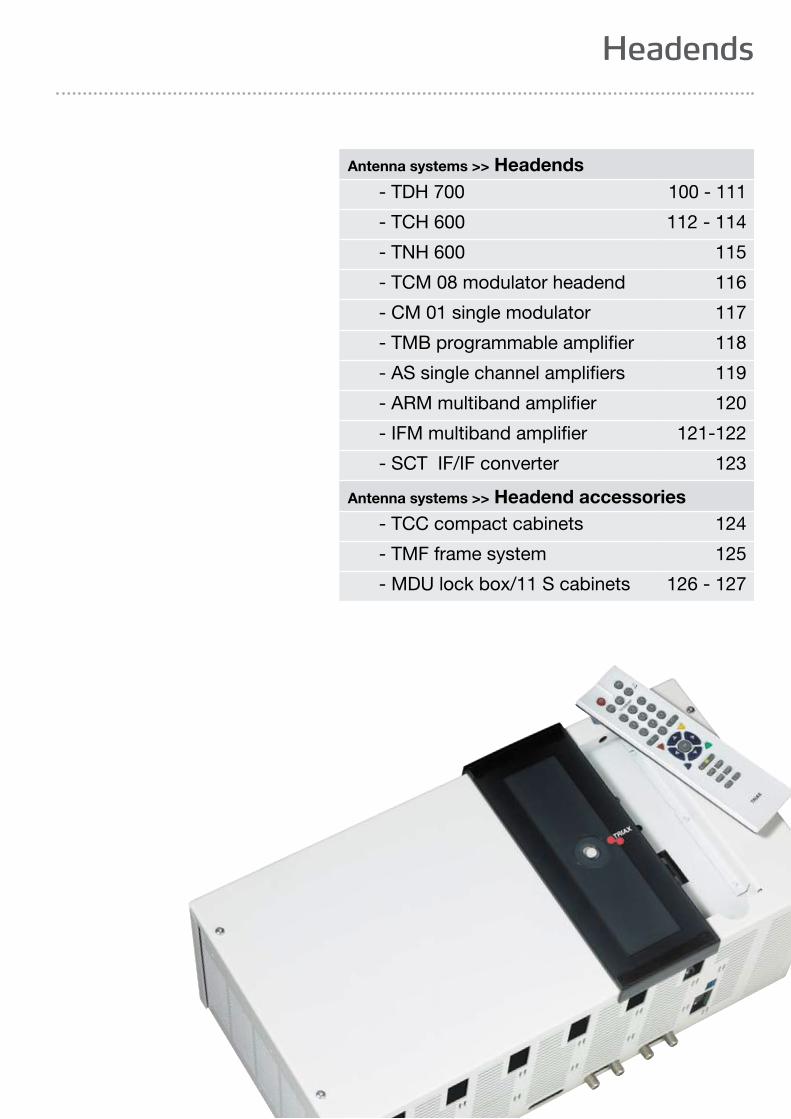
99
Headends
Antenna systems >> Headends - TDH 700 100 - 111
- TCH 600 112 - 114
- TNH 600 115
- TCM 08 modulator headend 116
- CM 01 single modulator 117
- TMB programmable amplifier 118
- AS single channel amplifiers 119
- ARM multiband amplifier 120
- IFM multiband amplifier 121-122
- SCT IF/IF converter 123
Antenna systems >> Headend accessories - TCC compact cabinets 124
- TMF frame system 125
- MDU lock box/11 S cabinets 126 - 127
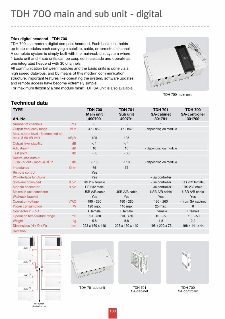
100
LINK
LINK
LINK
LINK
Technical dataTYPE
Art. No.
TDH 700Main unit490790
TDH 701Sub unit490791
TDH 791SA-cabinet
301791
TDH 700SA-controller
301700Number of channels Pcs 6 6 1Output frequency range MHz 47 - 862 47 - 862 - depending on moduleMax. output level - 6 combined ch.max. @ 60 dB IMD dBµV 105 105
Output level stability dB < 1 < 1Adjustment dB 10 10 - depending on moduleTest point dB - 30 - 30Return loss outputTv in - tv out - module RF in dB ≥ 10 ≥ 10 - depending on module
Impedance Ohm 75 75Remote control YesPC-interface functions Yes - via controllerSoftware download 9 pin RS 232 female - via controller RS 232 femaleModem connector 9 pin RS 232 male - via controller RS 232 maleMain/sub unit connector USB A/B cable USB A/B cable USB A/B cable USB A/B cableWall/rack bracket Yes Yes Yes YesOperation voltage V/AC 190 - 260 190 - 260 190 - 260 - from SA cabinetPower consumption W 120 max. 110 max. 25 max. 8Connector in - out F female F female F female F femaleOperation temperature range oC -10...+50 -10...+50 -10...+50 -10...+50Weight kg 5.8 5.8 1.8 2.2Dimensions (H x D x W) mm 223 x 160 x 440 223 x 160 x 440 198 x 220 x 76 198 x 141 x 44
Remarks
TDH 700 main and sub unit - digital
Triax digital headend - TDH 700TDH 700 is a modern digital compact headend. Each basic unit holds up to six modules each carrying a satellite, cable, or terrestrial channel.A complete system is simply built with the main/sub unit system where 1 basic unit and 4 sub units can be coupled in cascade and operate as one integrated headend with 30 channels. All communication between modules and the basic units is done via a high speed data-bus, and by means of this modern communication structure, important features like operating the system, software updates, and remote access have become extremely simple. For maximum flexibility a one module basic TDH SA unit is also avaiable.
TDH 700 main unit
TDH 701sub unit TDH 791 SA-cabinet
TDH 700 SA-controller
RF-out for distribution net
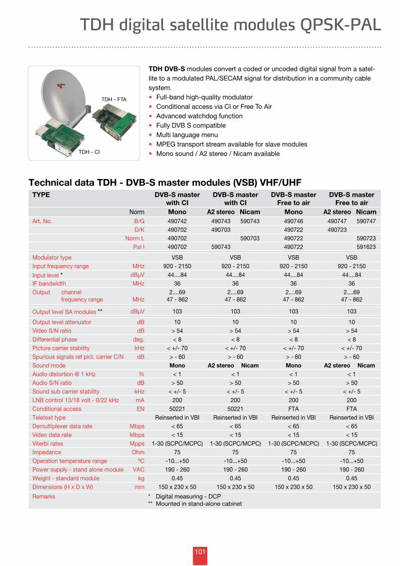
101
TYPE DVB-S masterwith CI
DVB-S masterwith CI
DVB-S masterFree to air
DVB-S masterFree to air
Norm Mono A2 stereo Nicam Mono A2 stereo NicamArt. No. B/G 490742 490743 590743 490746 490747 590747
D/K 490702 490703 490722 490723Norm L 490702 590703 490722 590723
Pal I 490702 590743 490722 591623
Modulator type VSB VSB VSB VSBInput frequency range MHz 920 - 2150 920 - 2150 920 - 2150 920 - 2150
Input level * dBµV 44....84 44....84 44....84 44....84IF bandwidth MHz 36 36 36 36Output channel frequency range MHz
2....6947 - 862
2....6947 - 862
2....6947 - 862
2....6947 - 862
Output level SA modules ** dBµV 103 103 103 103
Output level attenuator dB 10 10 10 10Video S/N ratio dB > 54 > 54 > 54 > 54Differential phase deg. < 8 < 8 < 8 < 8Picture carrier stability kHz < +/- 70 < +/- 70 < +/- 70 < +/- 70Spurious signals ref pict. carrier C/N dB > - 60 > - 60 > - 60 > - 60Sound mode Mono A2 stereo Nicam Mono A2 stereo NicamAudio distortion @ 1 kHz % < 1 < 1 < 1 < 1Audio S/N ratio dB > 50 > 50 > 50 > 50Sound sub carrier stability kHz < +/- 5 < +/- 5 < +/- 5 < +/- 5LNB control 13/18 volt - 0/22 kHz mA 200 200 200 200Conditional access EN 50221 50221 FTA FTATeletext type Reinserted in VBI Reinserted in VBI Reinserted in VBI Reinserted in VBIDemultiplexer data rate Mbps < 65 < 65 < 65 < 65Video data rate Mbps < 15 < 15 < 15 < 15Viterbi rates Mpps 1-30 (SCPC/MCPC) 1-30 (SCPC/MCPC) 1-30 (SCPC/MCPC) 1-30 (SCPC/MCPC)Impedance Ohm 75 75 75 75Operation temperature range oC -10...+50 -10...+50 -10...+50 -10...+50Power supply - stand alone module VAC 190 - 260 190 - 260 190 - 260 190 - 260Weight - standard module kg 0.45 0.45 0.45 0.45Dimensions (H x D x W) mm 150 x 230 x 50 150 x 230 x 50 150 x 230 x 50 150 x 230 x 50
Remarks * Digital measuring - DCP** Mounted in stand-alone cabinet
TDH digital satellite modules QPSK-PAL
Technical data TDH - DVB-S master modules (VSB) VHF/UHF
TDH DVB-S modules convert a coded or uncoded digital signal from a satel-lite to a modulated PAL/SECAM signal for distribution in a community cable system.• Full-band high-quality modulator • Conditional access via CI or Free To Air • Advanced watchdog function • Fully DVB S compatible • Multi language menu • MPEG transport stream available for slave modules • Mono sound / A2 stereo / Nicam available TDH - CI
TDH - FTA
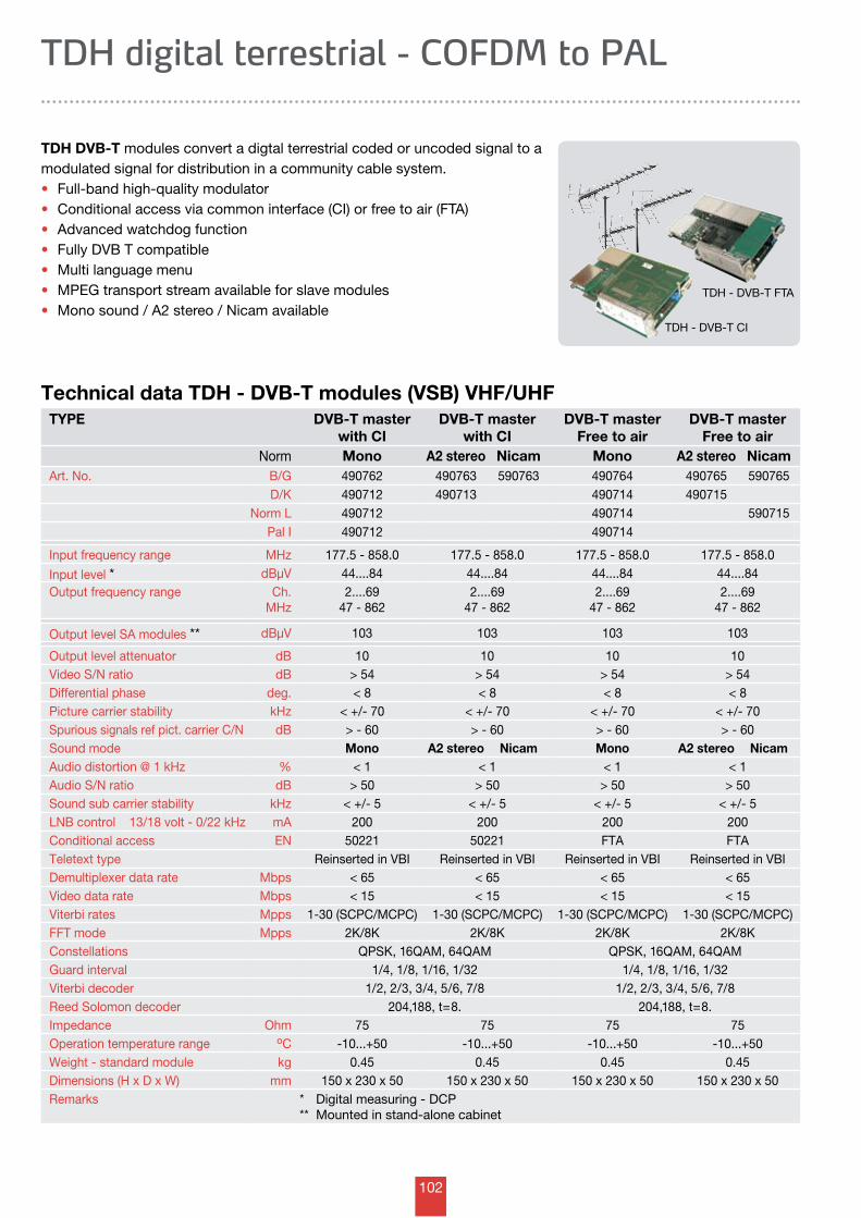
102
Technical data TDH - DVB-T modules (VSB) VHF/UHF
TDH digital terrestrial - COFDM to PAL
TDH DVB-T modules convert a digtal terrestrial coded or uncoded signal to a modulated signal for distribution in a community cable system.• Full-band high-quality modulator • Conditional access via common interface (CI) or free to air (FTA) • Advanced watchdog function• Fully DVB T compatible • Multi language menu • MPEG transport stream available for slave modules • Mono sound / A2 stereo / Nicam available
TYPE DVB-T masterwith CI
DVB-T masterwith CI
DVB-T masterFree to air
DVB-T masterFree to air
Norm Mono A2 stereo Nicam Mono A2 stereo NicamArt. No. B/G 490762 490763 590763 490764 490765 590765
D/K 490712 490713 490714 490715Norm L 490712 490714 590715
Pal I 490712 490714
Input frequency range MHz 177.5 - 858.0 177.5 - 858.0 177.5 - 858.0 177.5 - 858.0
Input level * dBµV 44....84 44....84 44....84 44....84Output frequency range Ch.
MHz2....69
47 - 8622....69
47 - 8622....69
47 - 8622....69
47 - 862
Output level SA modules ** dBµV 103 103 103 103
Output level attenuator dB 10 10 10 10Video S/N ratio dB > 54 > 54 > 54 > 54Differential phase deg. < 8 < 8 < 8 < 8Picture carrier stability kHz < +/- 70 < +/- 70 < +/- 70 < +/- 70Spurious signals ref pict. carrier C/N dB > - 60 > - 60 > - 60 > - 60Sound mode Mono A2 stereo Nicam Mono A2 stereo NicamAudio distortion @ 1 kHz % < 1 < 1 < 1 < 1Audio S/N ratio dB > 50 > 50 > 50 > 50Sound sub carrier stability kHz < +/- 5 < +/- 5 < +/- 5 < +/- 5LNB control 13/18 volt - 0/22 kHz mA 200 200 200 200Conditional access EN 50221 50221 FTA FTATeletext type Reinserted in VBI Reinserted in VBI Reinserted in VBI Reinserted in VBIDemultiplexer data rate Mbps < 65 < 65 < 65 < 65Video data rate Mbps < 15 < 15 < 15 < 15Viterbi rates Mpps 1-30 (SCPC/MCPC) 1-30 (SCPC/MCPC) 1-30 (SCPC/MCPC) 1-30 (SCPC/MCPC)FFT mode Mpps 2K/8K 2K/8K 2K/8K 2K/8KConstellations QPSK, 16QAM, 64QAM QPSK, 16QAM, 64QAMGuard interval 1/4, 1/8, 1/16, 1/32 1/4, 1/8, 1/16, 1/32Viterbi decoder 1/2, 2/3, 3/4, 5/6, 7/8 1/2, 2/3, 3/4, 5/6, 7/8Reed Solomon decoder 204,188, t=8. 204,188, t=8.Impedance Ohm 75 75 75 75Operation temperature range oC -10...+50 -10...+50 -10...+50 -10...+50Weight - standard module kg 0.45 0.45 0.45 0.45Dimensions (H x D x W) mm 150 x 230 x 50 150 x 230 x 50 150 x 230 x 50 150 x 230 x 50Remarks * Digital measuring - DCP
** Mounted in stand-alone cabinet
TDH - DVB-T CI
TDH - DVB-T FTA
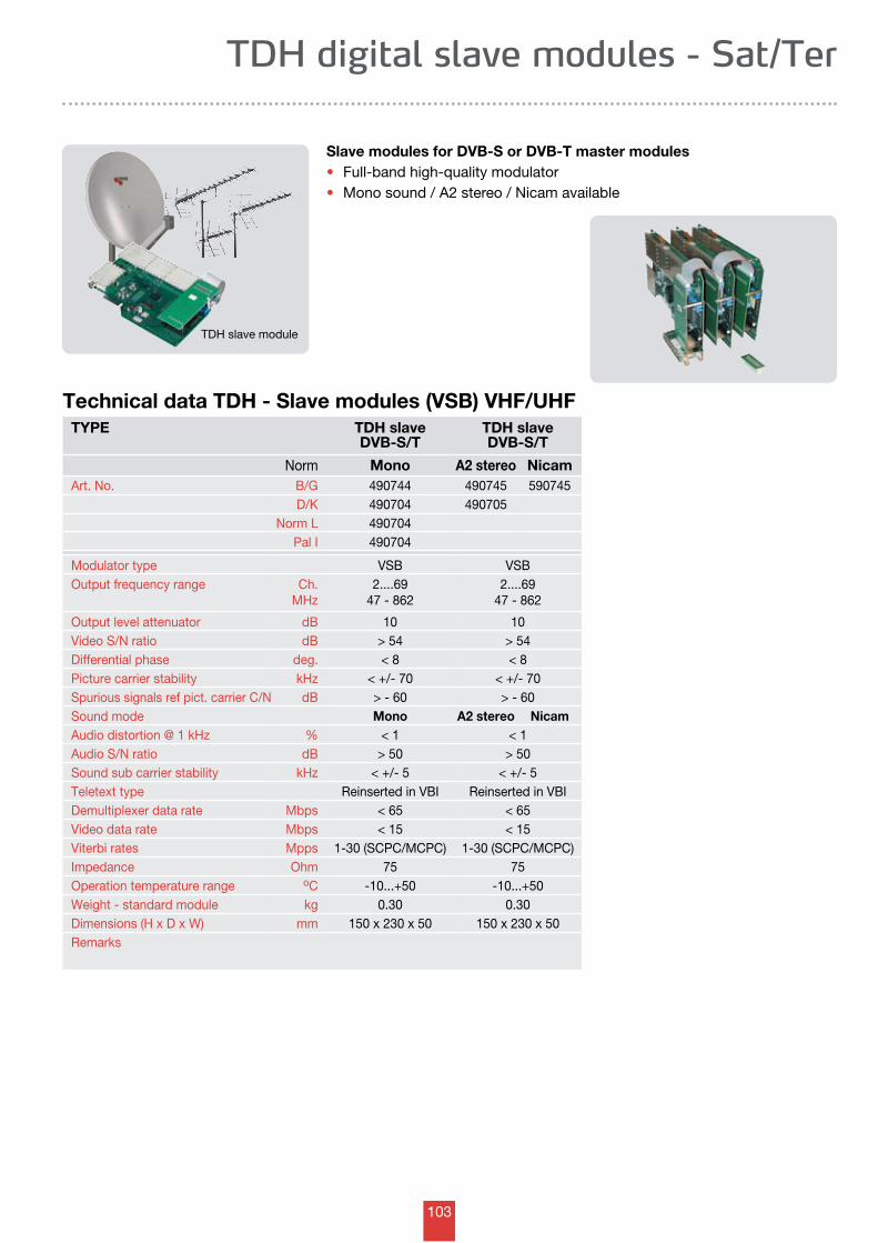
103
TYPE TDH slaveDVB-S/T
TDH slaveDVB-S/T
Norm Mono A2 stereo NicamArt. No. B/G 490744 490745 590745
D/K 490704 490705Norm L 490704
Pal I 490704
Modulator type VSB VSBOutput frequency range Ch.
MHz2....69
47 - 8622....69
47 - 862
Output level attenuator dB 10 10Video S/N ratio dB > 54 > 54Differential phase deg. < 8 < 8Picture carrier stability kHz < +/- 70 < +/- 70Spurious signals ref pict. carrier C/N dB > - 60 > - 60Sound mode Mono A2 stereo NicamAudio distortion @ 1 kHz % < 1 < 1Audio S/N ratio dB > 50 > 50Sound sub carrier stability kHz < +/- 5 < +/- 5Teletext type Reinserted in VBI Reinserted in VBIDemultiplexer data rate Mbps < 65 < 65Video data rate Mbps < 15 < 15Viterbi rates Mpps 1-30 (SCPC/MCPC) 1-30 (SCPC/MCPC)Impedance Ohm 75 75Operation temperature range oC -10...+50 -10...+50Weight - standard module kg 0.30 0.30Dimensions (H x D x W) mm 150 x 230 x 50 150 x 230 x 50Remarks
TDH digital slave modules - Sat/Ter
Technical data TDH - Slave modules (VSB) VHF/UHF
Slave modules for DVB-S or DVB-T master modules• Full-band high-quality modulator • Mono sound / A2 stereo / Nicam available
TDH slave module
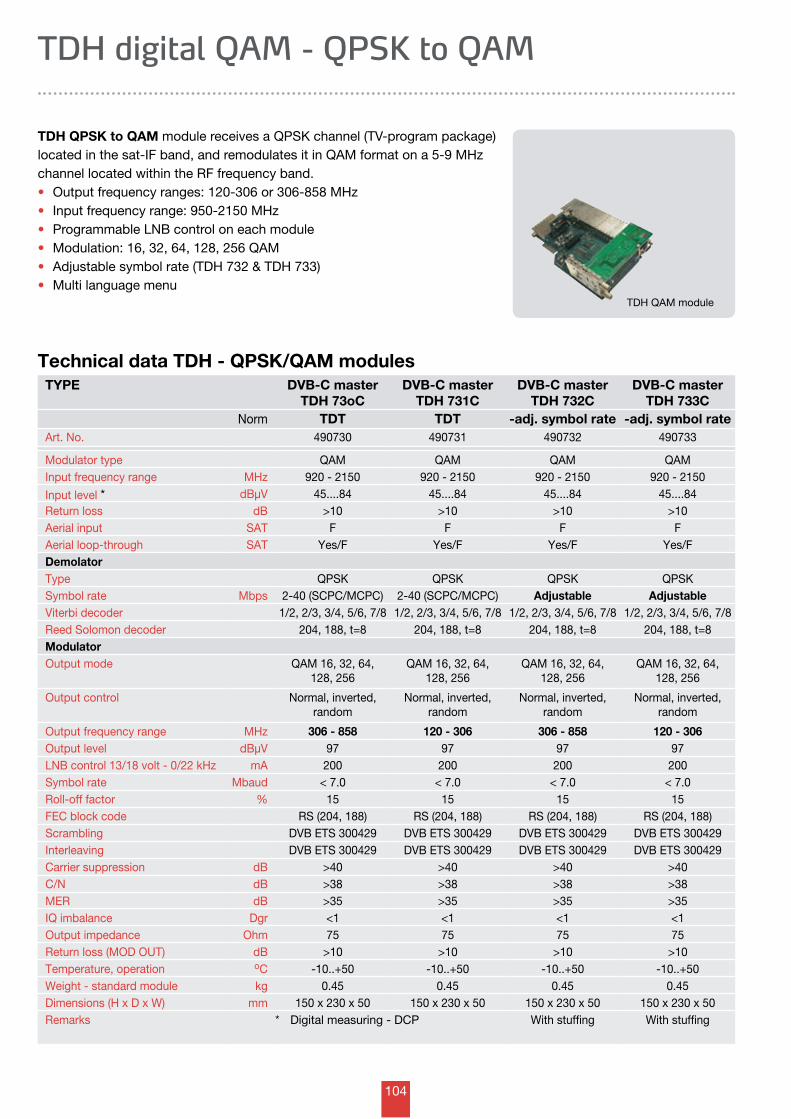
104
Technical data TDH - QPSK/QAM modulesTYPE DVB-C master
TDH 73oCDVB-C master
TDH 731CDVB-C master
TDH 732CDVB-C master
TDH 733CNorm TDT TDT -adj. symbol rate -adj. symbol rate
Art. No. 490730 490731 490732 490733
Modulator type QAM QAM QAM QAMInput frequency range MHz 920 - 2150 920 - 2150 920 - 2150 920 - 2150
Input level * dBµV 45....84 45....84 45....84 45....84Return loss dB >10 >10 >10 >10Aerial input SAT F F F FAerial loop-through SAT Yes/F Yes/F Yes/F Yes/FDemolatorType QPSK QPSK QPSK QPSKSymbol rate Mbps 2-40 (SCPC/MCPC) 2-40 (SCPC/MCPC) Adjustable AdjustableViterbi decoder 1/2, 2/3, 3/4, 5/6, 7/8 1/2, 2/3, 3/4, 5/6, 7/8 1/2, 2/3, 3/4, 5/6, 7/8 1/2, 2/3, 3/4, 5/6, 7/8Reed Solomon decoder 204, 188, t=8 204, 188, t=8 204, 188, t=8 204, 188, t=8ModulatorOutput mode QAM 16, 32, 64,
128, 256QAM 16, 32, 64,
128, 256QAM 16, 32, 64,
128, 256QAM 16, 32, 64,
128, 256
Output control Normal, inverted, random
Normal, inverted, random
Normal, inverted, random
Normal, inverted, random
Output frequency range MHz 306 - 858 120 - 306 306 - 858 120 - 306Output level dBµV 97 97 97 97LNB control 13/18 volt - 0/22 kHz mA 200 200 200 200Symbol rate Mbaud < 7.0 < 7.0 < 7.0 < 7.0Roll-off factor % 15 15 15 15FEC block code RS (204, 188) RS (204, 188) RS (204, 188) RS (204, 188)Scrambling DVB ETS 300429 DVB ETS 300429 DVB ETS 300429 DVB ETS 300429Interleaving DVB ETS 300429 DVB ETS 300429 DVB ETS 300429 DVB ETS 300429Carrier suppression dB >40 >40 >40 >40C/N dB >38 >38 >38 >38MER dB >35 >35 >35 >35IQ imbalance Dgr <1 <1 <1 <1Output impedance Ohm 75 75 75 75Return loss (MOD OUT) dB >10 >10 >10 >10Temperature, operation oC -10..+50 -10..+50 -10..+50 -10..+50Weight - standard module kg 0.45 0.45 0.45 0.45Dimensions (H x D x W) mm 150 x 230 x 50 150 x 230 x 50 150 x 230 x 50 150 x 230 x 50Remarks * Digital measuring - DCP With stuffing With stuffing
TDH QPSK to QAM module receives a QPSK channel (TV-program package) located in the sat-IF band, and remodulates it in QAM format on a 5-9 MHz channel located within the RF frequency band. • Output frequency ranges: 120-306 or 306-858 MHz• Input frequency range: 950-2150 MHz• Programmable LNB control on each module• Modulation: 16, 32, 64, 128, 256 QAM• Adjustable symbol rate (TDH 732 & TDH 733)• Multi language menu
TDH digital QAM - QPSK to QAM
TDH QAM module
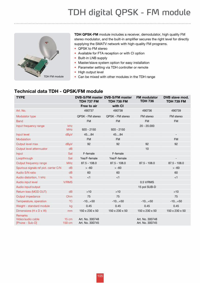
105
TYPE DVB-S/FM masterTDH 737 FM
DVB-S/FM master TDH 738 FM
FM modulatorTDH 736
DVB slave mod.TDH 739 FM
Free to air with CIArt. No. 490737 490738 490736 490739
Modulator type QPSK - FM stereo QPSK - FM stereo FM stereo FM stereo
Band FM FM FM FM
Input frequency range kHzMHz 920 - 2150 920 - 2150
20 - 20.000
Input level dBµV 45....84 45....84 -
Modulation FM FM FM
Output level max dBµV 92 92 92 92
Output level attennuator dB 10
Input Sat F-female F-female
Loopthrough Sat Yes/F-female Yes/F-female -
Output frequency range MHz 87.5 - 108.0 87.5 - 108.0 87.5 - 108.0 87.5 - 108.0
Spurious signals ref pict. carrier C/N dB > -60 > -60 > -60
Audio S/N ratio dB 60 60 60
Audio distortion, 1 kHz % <1 <1 <1
Audio input level V/RMS 0.5 V/RMS
Audio input/output 15 pol SUB-D
Return loss (MOD OUT) dB >10 >10 >10
Output impedance Ohm 75 75 75
Temperature, operation oC -10...+50 -10...+50 -10...+50 -10...+50
Weight - standard module kg 0.45 0.45 0.45 0.45
Dimensions (H x D x W) mm 150 x 230 x 50 150 x 230 x 50 150 x 230 x 50 150 x 230 x 50
Remarks Video/audio cable[Phone - Sub-D]
15 cm150 cm
Art. No. 300748Art. No. 300745
Art. No. 300748Art. No. 300745
TDH digital QPSK - FM module
TDH QPSK-FM module includes a receiver, demodulator, high quality FM stereo modulator, and the built-in amplifier secures the right level for directly supplying the SMATV network with high-quality FM programs.• QPSK to FM stereo• Available for FTA reception or with CI option • Built-in LNB supply • Master/slave system option for easy installation• Parameter setting via TDH controller or remote• High output level• Can be mixed with other modules in the TDH range
Technical data TDH - QPSK/FM module
TDH FM module
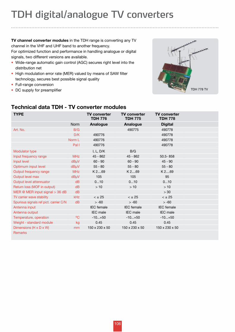
106
TYPE TV converterTDH 776
TV converterTDH 775
TV converterTDH 778
Norm Analogue Analogue DigitalArt. No. B/G 490775 490778
D/K 490776 490778Norm L 490776 490778
Pal I 490776 490778
Modulator type I, L, D/K B/GInput frequency range MHz 45 - 862 45 - 862 50.5- 858Input level dBµV 60 - 90 60 - 90 45 - 90Optimum input level dBµV 55 - 80 55 - 80 55 - 80Output frequency range MHz K 2....69 K 2....69 K 2....69Output level max dBµV 105 105 95Output level attennuator dB 0...10 0...10 0...10Return loss (MOF in output) dB > 10 > 10 > 10MER @ MER input signal > 36 dB dB > 30TV carrier wave stability kHz < ± 25 < ± 25 < ± 25Spurious signals ref pict. carrier C/N dB > -60 > -60 > -60Antenna input IEC female IEC female IEC femaleAntenna output IEC male IEC male IEC maleTemperature, operation oC -10...+50 -10...+50 -10...+50Weight - standard module kg 0.45 0.45 0.45Dimensions (H x D x W) mm 150 x 230 x 50 150 x 230 x 50 150 x 230 x 50Remarks
Technical data TDH - TV converter modules
TV channel converter modules in the TDH range is converting any TV channel in the VHF and UHF band to another frequency. For optimized function and performance in handling analogue or digital signals, two different versions are available.• Wide-range automatic gain control (AGC) secures right level into the distribution net• High modulation error rate (MER) valued by means of SAW filter technology, secures best possible signal quality • Full-range conversion• DC supply for preamplifier
TDH digital/analogue TV converters
TDH 778 TV
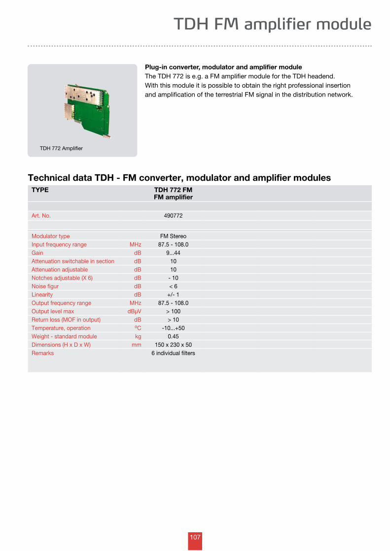
107
TDH FM amplifier module
Plug-in converter, modulator and amplifier moduleThe TDH 772 is e.g. a FM amplifier module for the TDH headend. With this module it is possible to obtain the right professional insertion and amplification of the terrestrial FM signal in the distribution network.
TDH 772 Amplifier
TYPE TDH 772 FMFM amplifier
Art. No. 490772
Modulator type FM StereoInput frequency range MHz 87.5 - 108.0Gain dB 9...44Attenuation switchable in section dB 10Attenuation adjustable dB 10Notches adjustable (X 6) dB - 10Noise figur dB < 6Linearity dB +/- 1Output frequency range MHz 87.5 - 108.0Output level max dBµV > 100Return loss (MOF in output) dB > 10Temperature, operation oC -10...+50Weight - standard module kg 0.45Dimensions (H x D x W) mm 150 x 230 x 50Remarks 6 individual filters
Technical data TDH - FM converter, modulator and amplifier modules
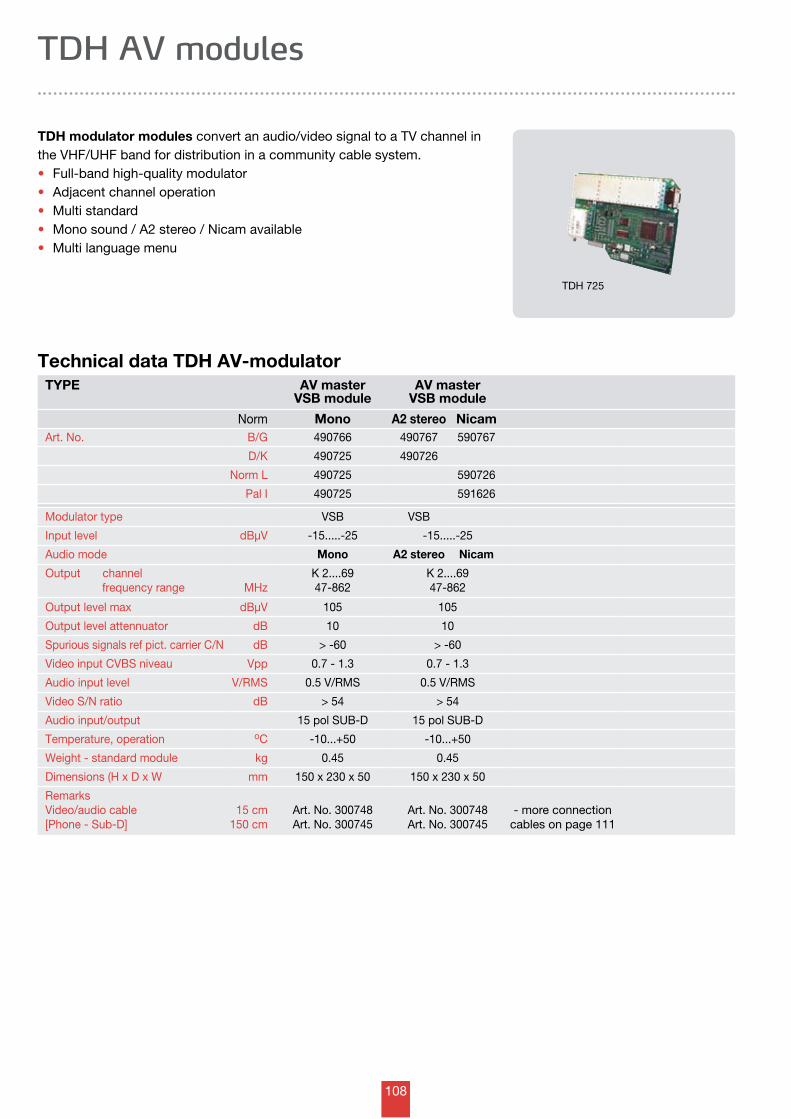
108
TDH modulator modules convert an audio/video signal to a TV channel in the VHF/UHF band for distribution in a community cable system.• Full-band high-quality modulator• Adjacent channel operation• Multi standard • Mono sound / A2 stereo / Nicam available • Multi language menu
TDH AV modules
TYPE AV masterVSB module
AV masterVSB module
Norm Mono A2 stereo NicamArt. No. B/G 490766 490767 590767
D/K 490725 490726
Norm L 490725 590726
Pal I 490725 591626
Modulator type VSB VSB
Input level dBµV -15.....-25 -15.....-25
Audio mode Mono A2 stereo Nicam
Output channel frequency range MHz
K 2....6947-862
K 2....6947-862
Output level max dBµV 105 105
Output level attennuator dB 10 10
Spurious signals ref pict. carrier C/N dB > -60 > -60
Video input CVBS niveau Vpp 0.7 - 1.3 0.7 - 1.3
Audio input level V/RMS 0.5 V/RMS 0.5 V/RMS
Video S/N ratio dB > 54 > 54
Audio input/output 15 pol SUB-D 15 pol SUB-D
Temperature, operation oC -10...+50 -10...+50
Weight - standard module kg 0.45 0.45
Dimensions (H x D x W mm 150 x 230 x 50 150 x 230 x 50
Remarks Video/audio cable[Phone - Sub-D]
15 cm150 cm
Art. No. 300748Art. No. 300745
Art. No. 300748Art. No. 300745
- more connection cables on page 111
Technical data TDH AV-modulator
TDH 725
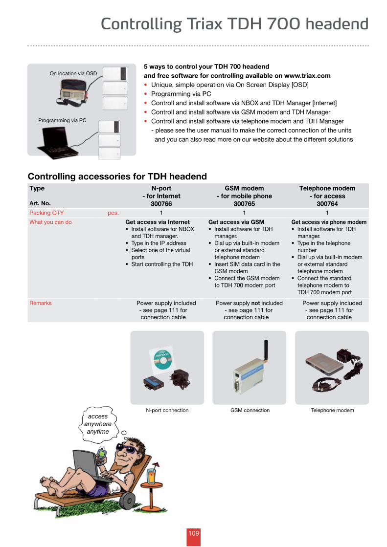
109
Controlling Triax TDH 700 headend
5 ways to control your TDH 700 headendand free software for controlling available on www.triax.com• Unique, simple operation via On Screen Display [OSD]• Programming via PC• Controll and install software via NBOX and TDH Manager [Internet]• Controll and install software via GSM modem and TDH Manager• Controll and install software via telephone modem and TDH Manager - please see the user manual to make the correct connection of the units and you can also read more on our website about the different solutions
Controlling accessories for TDH headend
accessanywhereanytime
Type
Art. No.
N-port- for Internet
300766
GSM modem- for mobile phone
300765
Telephone modem- for access
300764Packing QTY pcs. 1 1 1
What you can do Get access via Internet• InstallsoftwareforNBOX and TDH manager.• TypeintheIPaddress•Selectoneofthevirtual ports•StartcontrollingtheTDH
Get access via GSM• InstallsoftwareforTDH manager.• Dialupviabuilt-inmodem or external standard telephone modem• InsertSIMdatacardinthe GSM modem• ConnecttheGSMmodem to TDH 700 modem port
Get access via phone modem• InstallsoftwareforTDH manager.• Typeinthetelephone number• Dialupviabuilt-inmodem or external standard telephone modem• Connectthestandard telephone modem to TDH 700 modem port
Remarks Power supply included- see page 111 for connection cable
Power supply not included - see page 111 for
connection cable
Power supply included- see page 111 for connection cable
On location via OSD
Programming via PC
N-port connection GSM connection Telephone modem
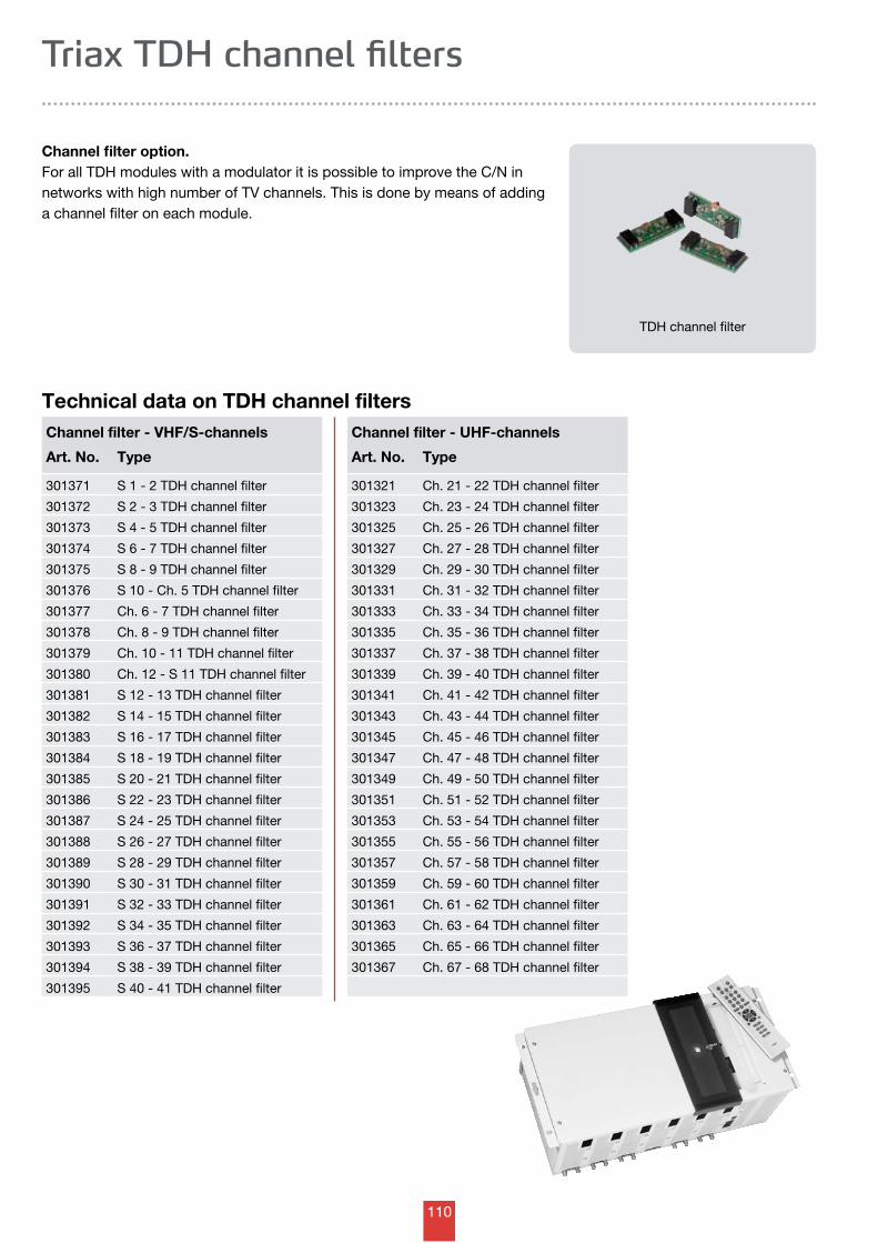
110
Channel filter option.For all TDH modules with a modulator it is possible to improve the C/N in networks with high number of TV channels. This is done by means of adding a channel filter on each module.
Triax TDH channel filters
Technical data on TDH channel filters
TDH channel filter
Channel filter - UHF-channels
Art. No. Type
301321 Ch. 21 - 22 TDH channel filter
301323 Ch. 23 - 24 TDH channel filter
301325 Ch. 25 - 26 TDH channel filter
301327 Ch. 27 - 28 TDH channel filter
301329 Ch. 29 - 30 TDH channel filter
301331 Ch. 31 - 32 TDH channel filter
301333 Ch. 33 - 34 TDH channel filter
301335 Ch. 35 - 36 TDH channel filter
301337 Ch. 37 - 38 TDH channel filter
301339 Ch. 39 - 40 TDH channel filter
301341 Ch. 41 - 42 TDH channel filter
301343 Ch. 43 - 44 TDH channel filter
301345 Ch. 45 - 46 TDH channel filter
301347 Ch. 47 - 48 TDH channel filter
301349 Ch. 49 - 50 TDH channel filter
301351 Ch. 51 - 52 TDH channel filter
301353 Ch. 53 - 54 TDH channel filter
301355 Ch. 55 - 56 TDH channel filter
301357 Ch. 57 - 58 TDH channel filter
301359 Ch. 59 - 60 TDH channel filter
301361 Ch. 61 - 62 TDH channel filter
301363 Ch. 63 - 64 TDH channel filter
301365 Ch. 65 - 66 TDH channel filter
301367 Ch. 67 - 68 TDH channel filter
Channel filter - VHF/S-channels
Art. No. Type
301371 S 1 - 2 TDH channel filter
301372 S 2 - 3 TDH channel filter
301373 S 4 - 5 TDH channel filter
301374 S 6 - 7 TDH channel filter
301375 S 8 - 9 TDH channel filter
301376 S 10 - Ch. 5 TDH channel filter
301377 Ch. 6 - 7 TDH channel filter
301378 Ch. 8 - 9 TDH channel filter
301379 Ch. 10 - 11 TDH channel filter
301380 Ch. 12 - S 11 TDH channel filter
301381 S 12 - 13 TDH channel filter
301382 S 14 - 15 TDH channel filter
301383 S 16 - 17 TDH channel filter
301384 S 18 - 19 TDH channel filter
301385 S 20 - 21 TDH channel filter
301386 S 22 - 23 TDH channel filter
301387 S 24 - 25 TDH channel filter
301388 S 26 - 27 TDH channel filter
301389 S 28 - 29 TDH channel filter
301390 S 30 - 31 TDH channel filter
301391 S 32 - 33 TDH channel filter
301392 S 34 - 35 TDH channel filter
301393 S 36 - 37 TDH channel filter
301394 S 38 - 39 TDH channel filter
301395 S 40 - 41 TDH channel filter
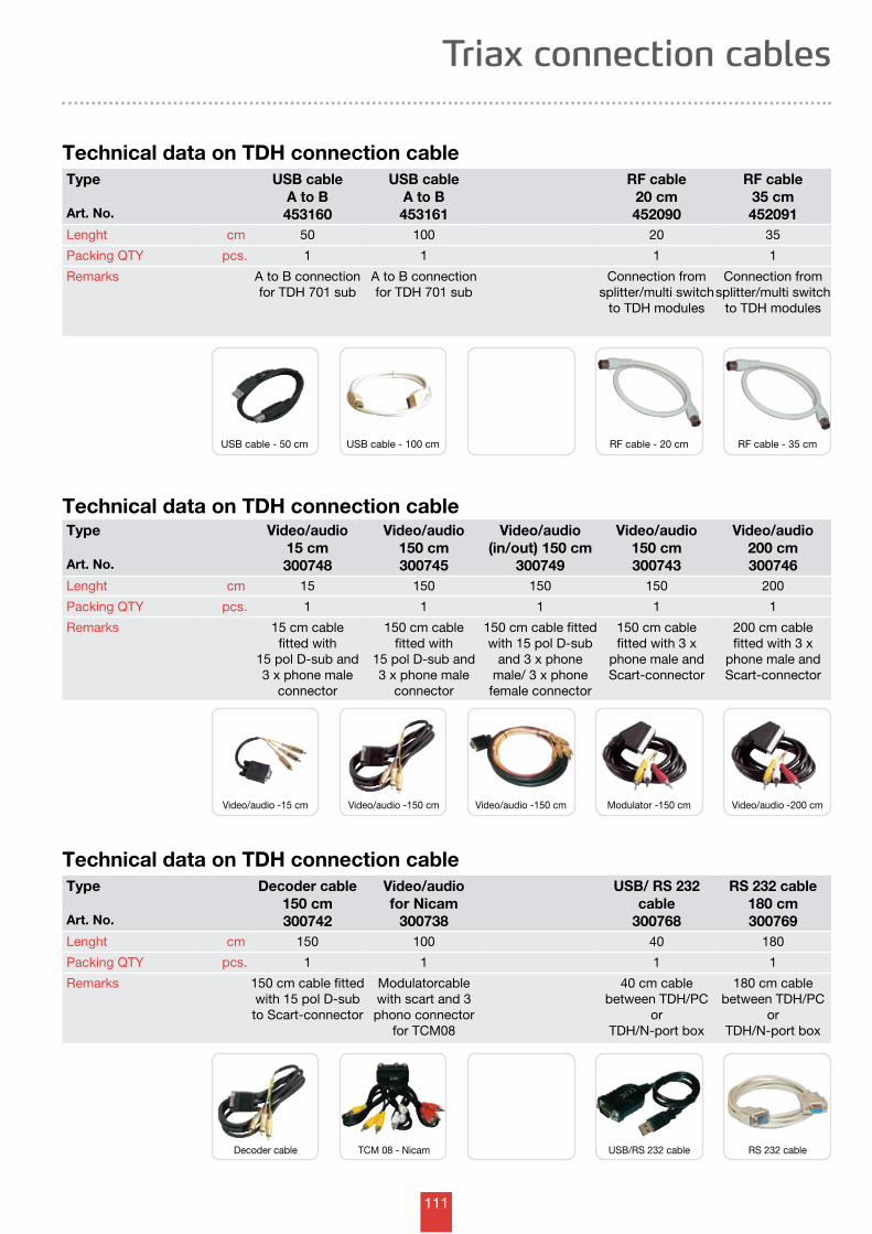
111
Triax connection cables
Type
Art. No.
USB cableA to B453160
USB cableA to B453161
RF cable20 cm452090
RF cable35 cm452091
Lenght cm 50 100 20 35
Packing QTY pcs. 1 1 1 1
Remarks A to B connectionfor TDH 701 sub
A to B connectionfor TDH 701 sub
Connection from splitter/multi switch
to TDH modules
Connection from splitter/multi switch
to TDH modules
Type
Art. No.
Decoder cable150 cm300742
Video/audiofor Nicam
300738
USB/ RS 232 cable
300768
RS 232 cable180 cm300769
Lenght cm 150 100 40 180
Packing QTY pcs. 1 1 1 1
Remarks 150 cm cable fitted with 15 pol D-sub to Scart-connector
Modulatorcable with scart and 3 phono connector
for TCM08
40 cm cable between TDH/PC
or TDH/N-port box
180 cm cable between TDH/PC
or TDH/N-port box
Technical data on TDH connection cable
Technical data on TDH connection cable
Technical data on TDH connection cableType
Art. No.
Video/audio15 cm300748
Video/audio150 cm300745
Video/audio(in/out) 150 cm
300749
Video/audio150 cm300743
Video/audio200 cm300746
Lenght cm 15 150 150 150 200
Packing QTY pcs. 1 1 1 1 1
Remarks 15 cm cable fitted with
15 pol D-sub and 3 x phone male
connector
150 cm cable fitted with
15 pol D-sub and 3 x phone male
connector
150 cm cable fitted with 15 pol D-sub
and 3 x phone male/ 3 x phone
female connector
150 cm cable fitted with 3 x
phone male andScart-connector
200 cm cable fitted with 3 x
phone male andScart-connector
USB cable - 50 cm USB cable - 100 cm RF cable - 20 cm RF cable - 35 cm
Video/audio -15 cm Video/audio -150 cm Video/audio -150 cm Modulator -150 cm Video/audio -200 cm
Decoder cable TCM 08 - Nicam USB/RS 232 cable RS 232 cable
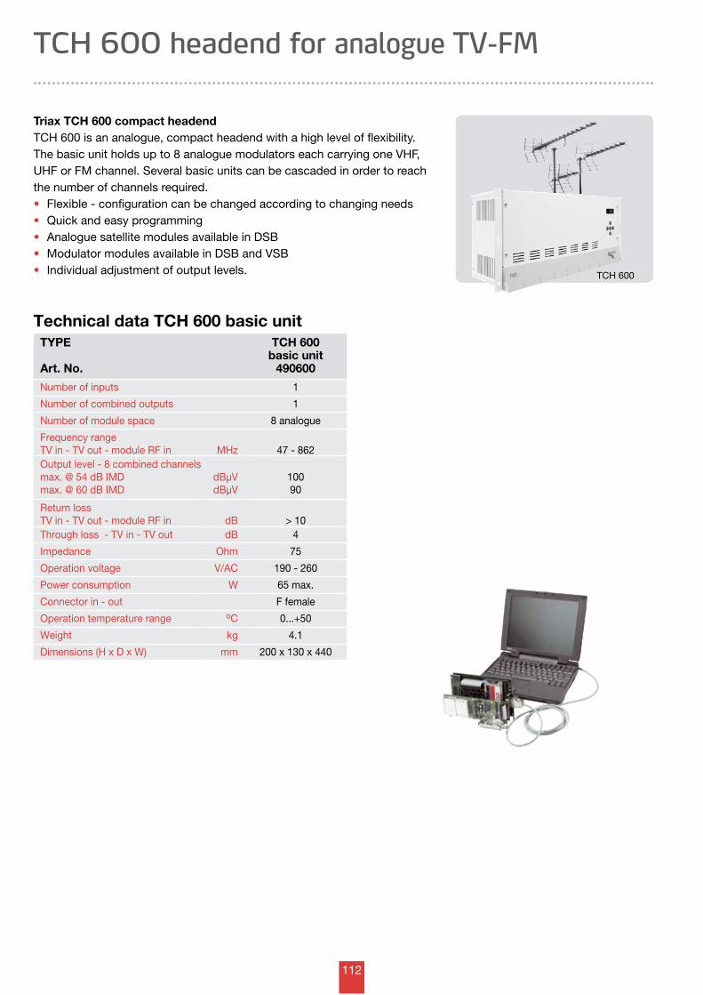
112
TYPE
Art. No.
TCH 600basic unit
490600
Number of inputs 1
Number of combined outputs 1
Number of module space 8 analogue
Frequency rangeTV in - TV out - module RF in MHz 47 - 862Output level - 8 combined channelsmax. @ 54 dB IMDmax. @ 60 dB IMD
dBµVdBµV
10090
Return lossTV in - TV out - module RF in dB > 10Through loss - TV in - TV out dB 4
Impedance Ohm 75
Operation voltage V/AC 190 - 260
Power consumption W 65 max.
Connector in - out F female
Operation temperature range oC 0...+50
Weight kg 4.1
Dimensions (H x D x W) mm 200 x 130 x 440
Technical data TCH 600 basic unit
Triax TCH 600 compact headendTCH 600 is an analogue, compact headend with a high level of flexibility.The basic unit holds up to 8 analogue modulators each carrying one VHF, UHF or FM channel. Several basic units can be cascaded in order to reach the number of channels required.• Flexible - configuration can be changed according to changing needs • Quick and easy programming • Analogue satellite modules available in DSB• Modulator modules available in DSB and VSB • Individual adjustment of output levels.
TCH 600 headend for analogue TV-FM
TCH 600
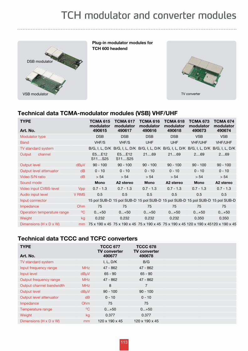
113
Technical data TCCC and TCFC convertersTYPE
Art. No.
TCCC 677TV converter
490677
TCCC 678TV converter
490678TV standard system I, L, D/K B/G
Input frequency range MHz 47 - 862 47 - 862
Input level dBµV 65 - 90 65 - 90
Output frequency range MHz 47 - 862 47 - 862
Output channel bandwidth MHz 8 7
Output level dBµV 90 - 100 90 - 100
Output level attenuator dB 0 - 10 0 - 10
Impedance Ohm 75 75
Temperature range oC 0...+50 0...+50
Weight kg 0.377 0.377
Dimensions (H x D x W) mm 120 x 190 x 45 120 x 190 x 45
TV converter
TCH modulator and converter modules
Technical data TCMA-modulator modules (VSB) VHF/UHFTYPE
Art. No.
TCMA 615modulator
490615
TCMA 617modulator
490617
TCMA 616modulator
490616
TCMA 618modulator
490618
TCMA 673modulator
490673
TCMA 674modulator
490674Modulator type DSB DSB DSB DSB VSB VSB
Band VHF/S VHF/S UHF UHF VHF/UHF VHF/UHF
TV standard system B/G, I, L, D/K B/G, I, L, D/K B/G, I, L, D/K B/G, I, L, D/K B/G, I, L, D/K B/G, I, L, D/K
Output channel
E5....E12 S11....S25
E5....E12 S11....S25
21....69 21....69 2....69 2....69
Output level dBµV 90 - 100 90 - 100 90 - 100 90 - 100 90 - 100 90 - 100
Output level attenuator dB 0 - 10 0 - 10 0 - 10 0 - 10 0 - 10 0 - 10
Video S/N ratio dB > 54 > 54 > 54 > 54 > 54 > 54
Sound mode Mono A2 stereo Mono A2 stereo Mono A2 stereo
Video input CVBS-level Vpp 0.7 - 1.3 0.7 - 1.3 0.7 - 1.3 0.7 - 1.3 0.7 - 1.3 0.7 - 1.3
Audio input level V RMS 0.5 0.5 0.5 0.5 0.5 0.5
Input connector 15 pol SUB-D 15 pol SUB-D 15 pol SUB-D 15 pol SUB-D 15 pol SUB-D 15 pol SUB-D
Impedance Ohm 75 75 75 75 75 75
Operation temperature range oC 0...+50 0...+50 0...+50 0...+50 0...+50 0...+50
Weight kg 0.232 0.232 0.232 0.232 0.350 0.350
Dimensions (H x D x W) mm 75 x 190 x 45 75 x 190 x 45 75 x 190 x 45 75 x 190 x 45 120 x 190 x 45120 x 190 x 45
Plug-in modulator modules for TCH 600 headend
VSB modulator
DSB modulator
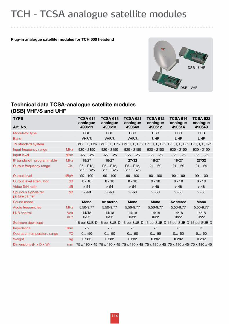
114
Plug-in analogue satellite modules for TCH 600 headend
TCH - TCSA analogue satellite modules
Technical data TCSA-analogue satellite modules (DSB) VHF/S and UHF
TYPE
Art. No.
TCSA 611analogue490611
TCSA 613analogue490613
TCSA 621analogue490648
TCSA 612analogue490612
TCSA 614analogue490614
TCSA 622analogue490649
Modulator type DSB DSB DSB DSB DSB DSB
Band VHF/S VHF/S VHF/S UHF UHF UHF
TV standard system B/G, I, L, D/K B/G, I, L, D/K B/G, I, L, D/K B/G, I, L, D/K B/G, I, L, D/K B/G, I, L, D/K
Input frequency range MHz 920 - 2150 920 - 2150 920 - 2150 920 - 2150 920 - 2150 920 - 2150
Input level dBm -65....-25 -65....-25 -65....-25 -65....-25 -65....-25 -65....-25
IF bandwidth programmable MHz 18/27 18/27 27/32 18/27 18/27 27/32
Output frequency range Ch. E5....E12, S11....S25
E5....E12, S11....S25
E5....E12, S11....S25
21....69 21....69 21....69
Output level dBµV 90 - 100 90 - 100 90 - 100 90 - 100 90 - 100 90 - 100
Output level attenuator dB 0 - 10 0 - 10 0 - 10 0 - 10 0 - 10 0 - 10
Video S/N ratio dB > 54 > 54 > 54 > 48 > 48 > 48
Spurious signals ref picture carrier
dB > -60 > -60 > -60 > -60 > -60 > -60
Sound mode Mono A2 stereo Mono Mono A2 stereo Mono
Audio frequencies MHz 5.50-9.77 5.50-9.77 5.50-9.77 5.50-9.77 5.50-9.77 5.50-9.77
LNB control VoltkHz
14/180/22
14/180/22
14/180/22
14/180/22
14/180/22
14/180/22
Software download 15 pol SUB-D 15 pol SUB-D 15 pol SUB-D 15 pol SUB-D 15 pol SUB-D 15 pol SUB-D
Impedance Ohm 75 75 75 75 75 75
Operation temperature range oC 0...+50 0...+50 0...+50 0...+50 0...+50 0...+50
Weight kg 0.282 0.282 0.282 0.282 0.282 0.282
Dimensions (H x D x W) mm 75 x 190 x 45 75 x 190 x 45 75 x 190 x 45 75 x 190 x 45 75 x 190 x 45 75 x 190 x 45
DSB - UHF
DSB - VHF
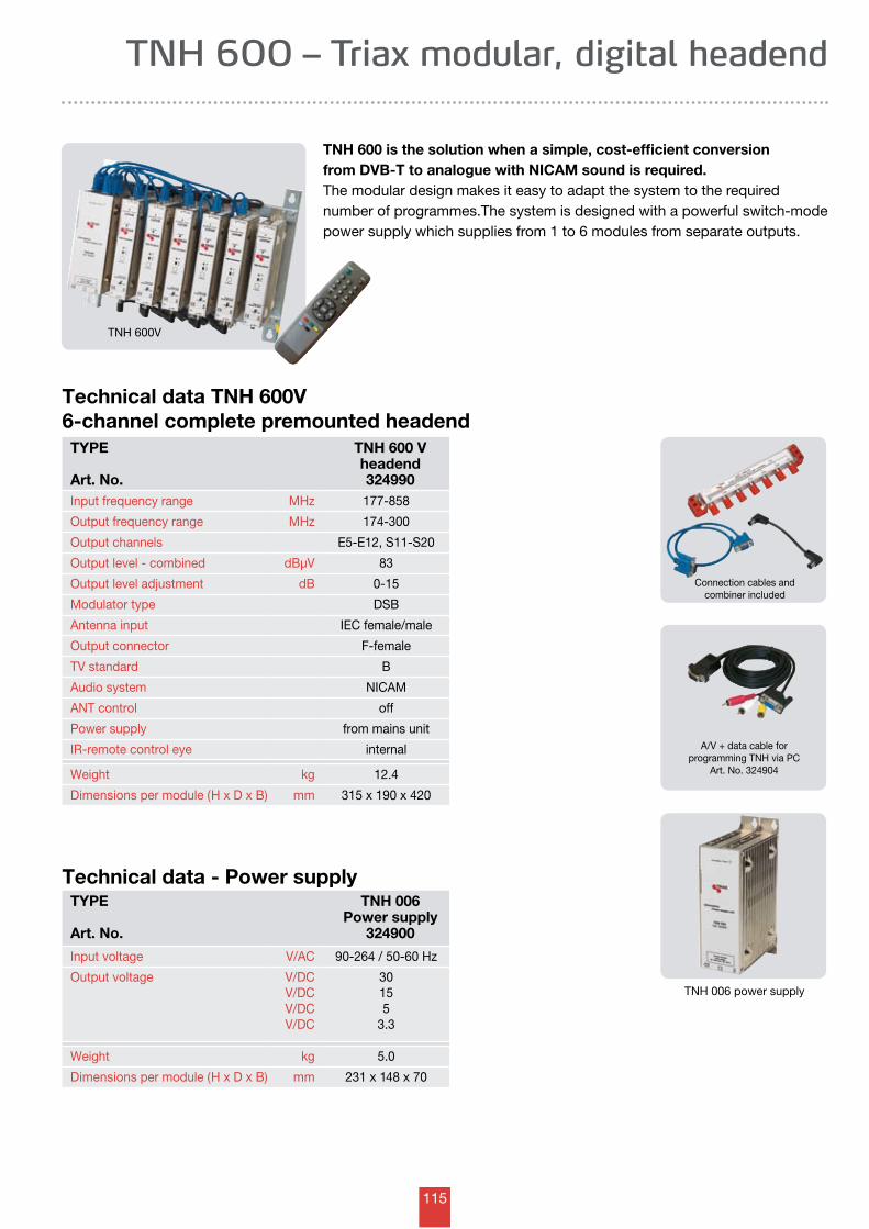
115
TNH 600 is the solution when a simple, cost-efficient conversion from DVB-T to analogue with NICAM sound is required.The modular design makes it easy to adapt the system to the required number of programmes.The system is designed with a powerful switch-mode power supply which supplies from 1 to 6 modules from separate outputs.
TNH 600 – Triax modular, digital headend
TNH 600V
Technical data TNH 600V6-channel complete premounted headend
TYPE
Art. No.
TNH 600 Vheadend324990
Input frequency range MHz 177-858
Output frequency range MHz 174-300
Output channels E5-E12, S11-S20
Output level - combined dBµV 83
Output level adjustment dB 0-15
Modulator type DSB
Antenna input IEC female/male
Output connector F-female
TV standard B
Audio system NICAM
ANT control off
Power supply from mains unit
IR-remote control eye internal
Weight kg 12.4
Dimensions per module (H x D x B) mm 315 x 190 x 420
Technical data - Power supplyTYPE
Art. No.
TNH 006Power supply
324900
Input voltage V/AC 90-264 / 50-60 Hz
Output voltage V/DCV/DCV/DCV/DC
30155
3.3
Weight kg 5.0
Dimensions per module (H x D x B) mm 231 x 148 x 70
A/V + data cable for programming TNH via PC
Art. No. 324904
Connection cables and combiner included
TNH 006 power supply
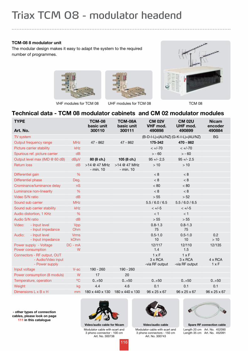
116
TCM-08 8 modulator unitThe modular design makes it easy to adapt the system to the required number of programmes.
Triax TCM 08 - modulator headend
TCM 08
Length 20 cm Art. No. 452090Length 35 cm Art. No. 452091
Technical data - TCM 08 modulator cabinets and CM 02 modulator modulesTYPE
Art. No.
TCM-08basic unit
300110
TCM-08Abasic unit
300111
CM 02VVHF mod.
490898
CM 02UUHF mod.
490899
Nicamencoder490884
TV system (B-D-I-L)+(AU/NZ) (G-K-I-L)+(AU/NZ) BG
Output frequency range MHz 47 - 862 47 - 862 175-342 470 - 862
Picture carrier stability kHz < +/-70 < +/-70
Spurious ref. picture carrier dB > - 60 > - 60
Output level max (IMD @ 60 dB) dBµV 80 (8 ch.) 105 (8 ch.) 95 +/- 2,5 95 +/- 2.5
Return loss dB >14 @ 47 MHz- min. 10
>14 @ 47 MHz- min. 10
> 10 > 10
Differentiel gain % < 8 < 8
Differentiel phase Deg. < 8 < 8
Crominance/luminance delay nS < 80 < 80
Luminance non-linearity % < 8 < 8
Video S/N ratio dB > 55 > 52
Sound sub carrier MHz 5.5 / 6.0 / 6.5 5.5 / 6.0 / 6.5
Sound sub carrier stability kHz < +/-5 < +/-5
Audio distortion, 1 KHz % < 1 < 1
Audio S/N ratio dB > 55 > 55
Video: - Input level - Input impedance
VppOhm
0.8-1.375
0.8-1.375
Audio: - Input level - Input impedance
VrmskOhm
0.5-1.010
0.5-1.010
0.2> 10
Power supply - VoltagePower consumption
DC - mAW
12/1171.4
12/1101.5
12/135
Connectors - RF output, OUT - Audio/Video input - Power supply
1 x F3 x RCA
-via RF output
1 x F3 x RCA
-via RF output4 x RCA
1 x FInput voltage V-ac 190 - 260 190 - 260
Power consumption (8 moduls) W 17 20
Temperature, operation oC 0..+50 0..+50 0..+50 0..+50 0..+50
Weight kg 4.4 4.6 0.1 0.1 0.1
Dimensions L x B x H mm 180 x 440 x 130 180 x 440 x 130 96 x 25 x 67 96 x 25 x 67 96 x 25 x 67
Modulator cable with scart and 3 phone connectors - 150 cm
Art. No. 300743
Modulator cable with scart and 3 phono connector - 100 cm
Art. No. 300738
VHF modules for TCM 08
- other types of connection cables, please look on page
111 in this catalogue
UHF modules for TCM 08
Video/audio cable for Nicam Video/audio cable Spare RF connection cable
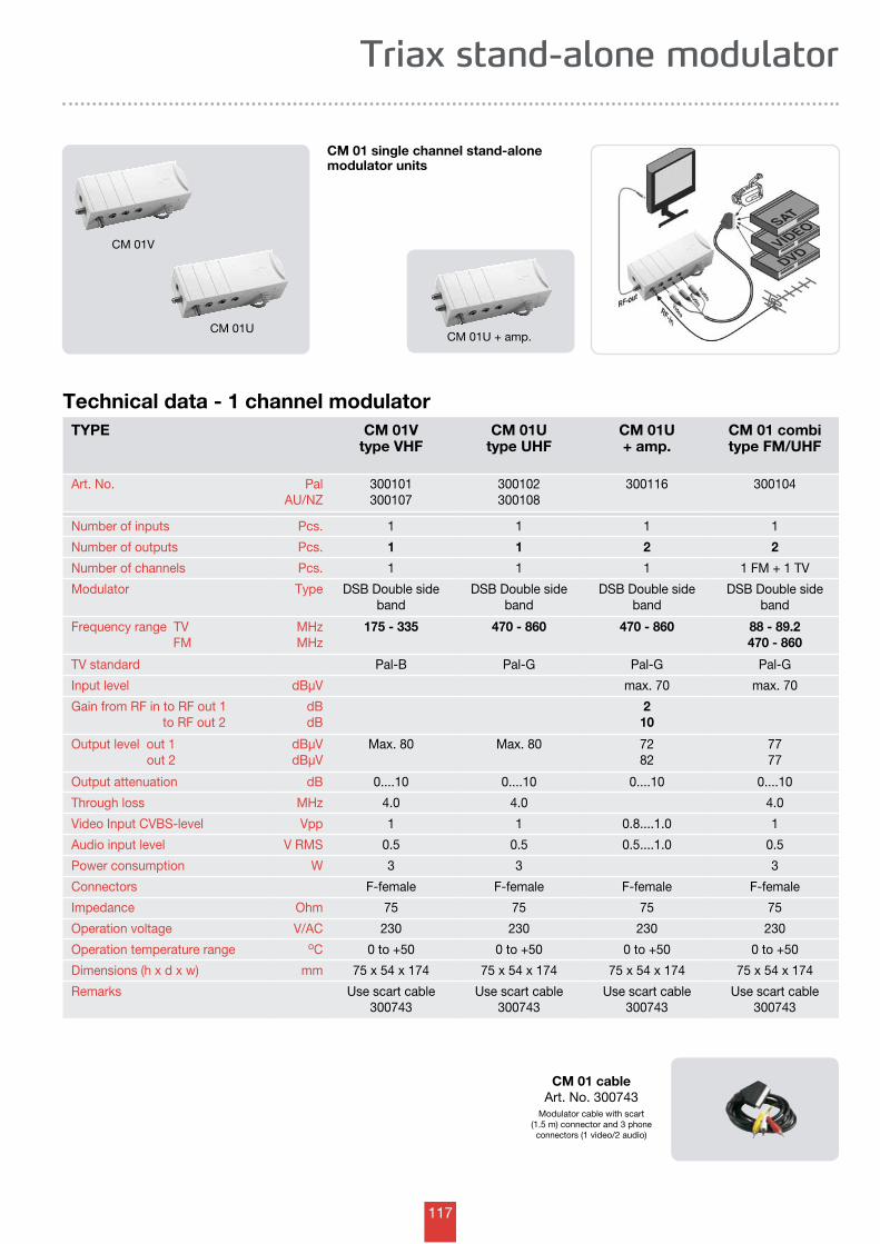
117
Triax stand-alone modulator
CM 01 single channel stand-alone modulator units
CM 01V
Technical data - 1 channel modulatorTYPE CM 01V
type VHFCM 01U
type UHFCM 01U+ amp.
CM 01 combitype FM/UHF
Art. No. PalAU/NZ
300101300107
300102300108
300116 300104
Number of inputs Pcs. 1 1 1 1
Number of outputs Pcs. 1 1 2 2
Number of channels Pcs. 1 1 1 1 FM + 1 TV
Modulator Type DSB Double side band
DSB Double side band
DSB Double side band
DSB Double side band
Frequency range TV FM
MHzMHz
175 - 335 470 - 860 470 - 860 88 - 89.2470 - 860
TV standard Pal-B Pal-G Pal-G Pal-G
Input level dBµV max. 70 max. 70
Gain from RF in to RF out 1 to RF out 2
dBdB
210
Output level out 1 out 2
dBµVdBµV
Max. 80 Max. 80 7282
7777
Output attenuation dB 0....10 0....10 0....10 0....10
Through loss MHz 4.0 4.0 4.0
Video Input CVBS-level Vpp 1 1 0.8....1.0 1
Audio input level V RMS 0.5 0.5 0.5....1.0 0.5
Power consumption W 3 3 3
Connectors F-female F-female F-female F-female
Impedance Ohm 75 75 75 75
Operation voltage V/AC 230 230 230 230
Operation temperature range oC 0 to +50 0 to +50 0 to +50 0 to +50
Dimensions (h x d x w) mm 75 x 54 x 174 75 x 54 x 174 75 x 54 x 174 75 x 54 x 174
Remarks Use scart cable 300743
Use scart cable 300743
Use scart cable 300743
Use scart cable 300743
CM 01 cableArt. No. 300743
Modulator cable with scart(1.5 m) connector and 3 phone
connectors (1 video/2 audio)
CM 01UCM 01U + amp.
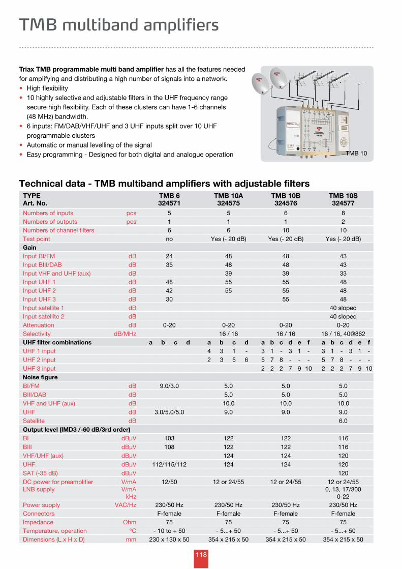
118
TMB multiband amplifiers
Triax TMB programmable multi band amplifier has all the features needed for amplifying and distributing a high number of signals into a network.• High flexibility • 10 highly selective and adjustable filters in the UHF frequency range secure high flexibility. Each of these clusters can have 1-6 channels (48 MHz) bandwidth.• 6 inputs: FM/DAB/VHF/UHF and 3 UHF inputs split over 10 UHF programmable clusters• Automatic or manual levelling of the signal• Easy programming - Designed for both digital and analogue operation TMB 10
Technical data - TMB multiband amplifiers with adjustable filtersTYPEArt. No.
TMB 6324571
TMB 10A324575
TMB 10B324576
TMB 10S324577
Numbers of inputs pcs 5 5 6 8Numbers of outputs pcs 1 1 1 2Numbers of channel filters 6 6 10 10Test point no Yes (- 20 dB) Yes (- 20 dB) Yes (- 20 dB)GainInput BI/FM dB 24 48 48 43Input BIII/DAB dB 35 48 48 43Input VHF and UHF (aux) dB 39 39 33Input UHF 1 dB 48 55 55 48Input UHF 2 dB 42 55 55 48Input UHF 3 dB 30 55 48Input satellite 1 dB 40 slopedInput satellite 2 dB 40 slopedAttenuation dB 0-20 0-20 0-20 0-20Selectivity dB/MHz 16 / 16 16 / 16 16 / 16, 40@862UHF filter combinations a b c d a b c d a b c d e f a b c d e fUHF 1 input 4 3 1 - 3 1 - 3 1 - 3 1 - 3 1 -UHF 2 input 2 3 5 6 5 7 8 - - - 5 7 8 - - -UHF 3 input 2 2 2 7 9 10 2 2 2 7 9 10
Noise figureBI/FM dB 9.0/3.0 5.0 5.0 5.0BIII/DAB dB 5.0 5.0 5.0VHF and UHF (aux) dB 10.0 10.0 10.0UHF dB 3.0/5.0/5.0 9.0 9.0 9.0Satellite dB 6.0Output level (IMD3 /-60 dB/3rd order) BI dBµV 103 122 122 116BIII dBµV 108 122 122 116VHF/UHF (aux) dBµV 124 124 120UHF dBµV 112/115/112 124 124 120SAT (-35 dB) dBµV 120DC power for preamplifier V/mA 12/50 12 or 24/55 12 or 24/55 12 or 24/55LNB supply V/mA
kHz0, 13, 17/300
0-22Power supply VAC/Hz 230/50 Hz 230/50 Hz 230/50 Hz 230/50 HzConnectors F-female F-female F-female F-femaleImpedance Ohm 75 75 75 75Temperature, operation ºC - 10 to + 50 - 5...+ 50 - 5...+ 50 - 5...+ 50Dimensions (L x H x D) mm 230 x 130 x 50 354 x 215 x 50 354 x 215 x 50 354 x 215 x 50
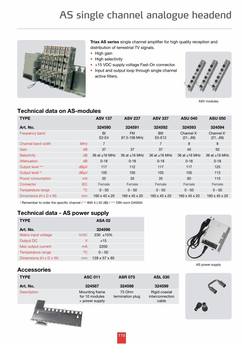
119
TYPE
Art. No.
ASV 137
324590
ASV 237
324591
ASV 337
324592
ASU 040
324593
ASU 050
324594Frequency band BI
E2-E4FM
87.5-108 MHzBIII
E5-E12Channel X*
(21...69)Channel X*
(21...69)
Channel band width MHz 7 7 8 8
Gain dB 37 37 37 40 50
Selectivity dB 36 at ±16 MHz 36 at ±16 MHz 36 at ±16 MHz 36 at ±16 MHz 36 at ±16 MHz
Attenuation dB 0-18 0-18 0-18 0-18 0-18
Output level *** dBµV 117 112 117 117 125
Output level ** dBµV 105 105 105 105 113
Power consumption mA 35 35 35 60 110
Connector IEC Female Female Female Female Female
Temperature range oC 0 - 50 0 - 50 0 - 50 0 - 50 0 - 50
Dimensions (H x D x W) mm 160 x 45 x 20 160 x 45 x 20 160 x 45 x 20 160 x 45 x 20 160 x 45 x 20
* Remember to order the specific channel / ** IMA 3 (-52 dB) / *** DIN norm D45004
Technical data - AS power supplyTYPE
Art. No.
ASA 02
324596Mains input voltage V/AC 230 ±10%
Output DC V +15
Max output current mA 2200
Temperature range oC 0 - 50
Dimensions (H x D x W) mm 128 x 57 x 85
AccessoriesTYPE
Art. No.
ASC 011
324587
ASR 075
324598
ASL 030
324599Description Mounting frame
for 10 modules + power supply
75 Ohm termination plug
Rigid coaxial interconnection
cable
AS single channel analogue headend
Triax AS series single channel amplifier for high quality reception and distribution of terrestrial TV signals. • High gain• High selectivity• +15 VDC supply voltage Fast-On connector.• Input and output loop through single channel active filters.
ASV modules
AS power supply
Technical data on AS-modules
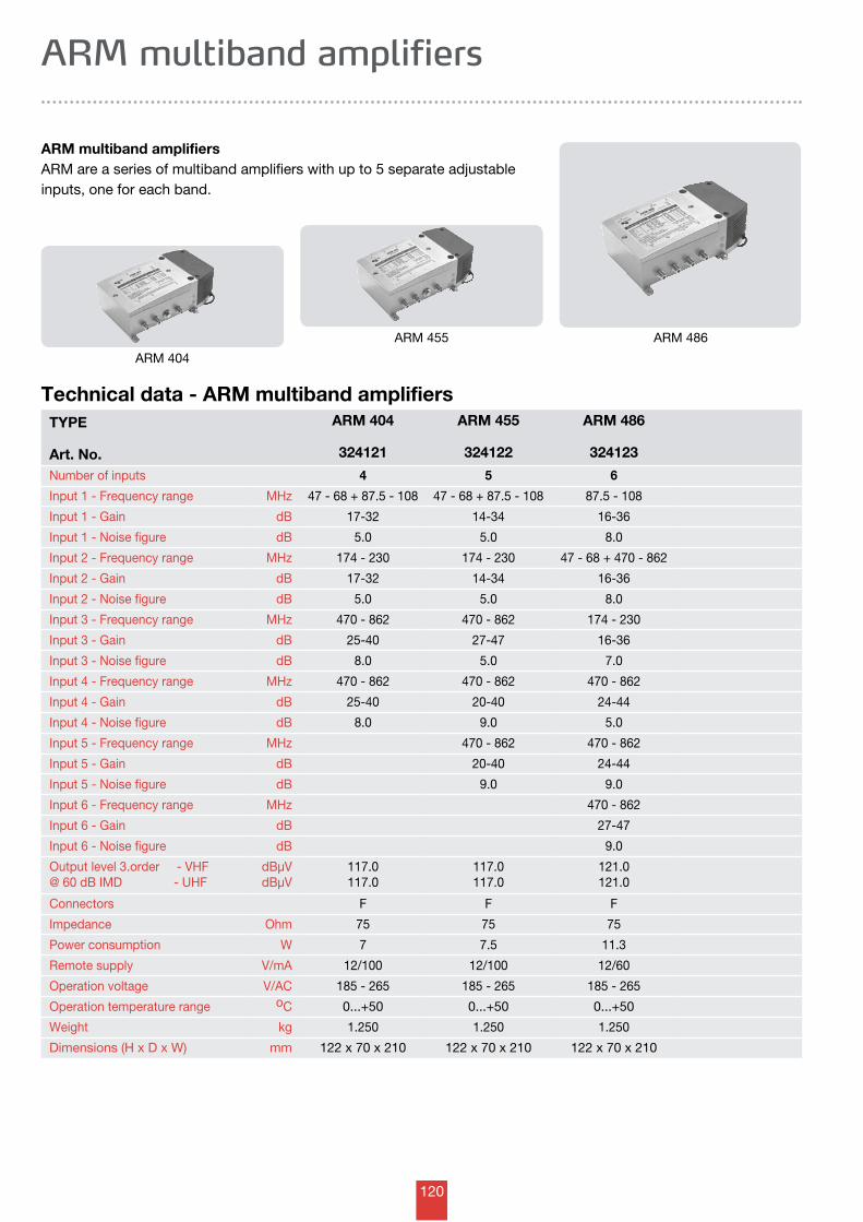
120
TYPE
Art. No.
ARM 404
324121
ARM 455
324122
ARM 486
324123
Number of inputs 4 5 6
Input 1 - Frequency range MHz 47 - 68 + 87.5 - 108 47 - 68 + 87.5 - 108 87.5 - 108
Input 1 - Gain dB 17-32 14-34 16-36
Input 1 - Noise figure dB 5.0 5.0 8.0
Input 2 - Frequency range MHz 174 - 230 174 - 230 47 - 68 + 470 - 862
Input 2 - Gain dB 17-32 14-34 16-36
Input 2 - Noise figure dB 5.0 5.0 8.0
Input 3 - Frequency range MHz 470 - 862 470 - 862 174 - 230
Input 3 - Gain dB 25-40 27-47 16-36
Input 3 - Noise figure dB 8.0 5.0 7.0
Input 4 - Frequency range MHz 470 - 862 470 - 862 470 - 862
Input 4 - Gain dB 25-40 20-40 24-44
Input 4 - Noise figure dB 8.0 9.0 5.0
Input 5 - Frequency range MHz 470 - 862 470 - 862
Input 5 - Gain dB 20-40 24-44
Input 5 - Noise figure dB 9.0 9.0
Input 6 - Frequency range MHz 470 - 862
Input 6 - Gain dB 27-47
Input 6 - Noise figure dB 9.0
Output level 3.order - VHF@ 60 dB IMD - UHF
dBµVdBµV
117.0117.0
117.0117.0
121.0121.0
Connectors F F F
Impedance Ohm 75 75 75
Power consumption W 7 7.5 11.3
Remote supply V/mA 12/100 12/100 12/60
Operation voltage V/AC 185 - 265 185 - 265 185 - 265
Operation temperature range oC 0...+50 0...+50 0...+50
Weight kg 1.250 1.250 1.250
Dimensions (H x D x W) mm 122 x 70 x 210 122 x 70 x 210 122 x 70 x 210
Technical data - ARM multiband amplifiers
ARM multiband amplifiersARM are a series of multiband amplifiers with up to 5 separate adjustable inputs, one for each band.
ARM multiband amplifiers
ARM 404
ARM 455 ARM 486
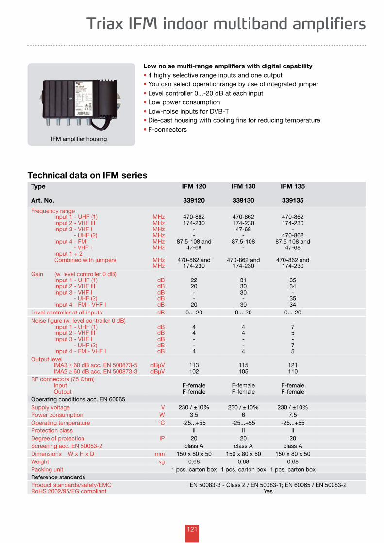
121
Triax IFM indoor multiband amplifiers
Low noise multi-range amplifiers with digital capability• 4 highly selective range inputs and one output• You can select operationrange by use of integrated jumper• Level controller 0...-20 dB at each input• Low power consumption• Low-noise inputs for DVB-T• Die-cast housing with cooling fins for reducing temperature• F-connectors
Technical data on IFM series
IFM amplifier housing
Type
Art. No.
IFM 120
339120
IFM 130
339130
IFM 135
339135
Frequency range Input 1 - UHF (1) Input 2 - VHF III Input 3 - VHF I - UHF (2) Input 4 - FM - VHF I Input 1 + 2 Combined with jumpers
MHzMHzMHzMHzMHzMHz
MHzMHz
470-862174-230
--
87.5-108 and47-68
470-862 and174-230
470-862174-23047-68
-87.5-108
-
470-862 and174-230
470-862174-230
-470-862
87.5-108 and47-68
470-862 and174-230
Gain (w. level controller 0 dB) Input 1 - UHF (1) Input 2 - VHF III Input 3 - VHF I - UHF (2) Input 4 - FM - VHF I
dBdBdBdBdB
2220--
20
313030-
30
3534-
3534
Level controller at all inputs dB 0...-20 0...-20 0...-20Noise figure (w. level controller 0 dB) Input 1 - UHF (1) Input 2 - VHF III Input 3 - VHF I - UHF (2) Input 4 - FM - VHF I
dBdBdBdBdB
44--4
44--4
75-75
Output level IMA3 ≥ 60 dB acc. EN 500873-5 IMA2 ≥ 60 dB acc. EN 500873-3
dBµVdBµV
113102
115105
121110
RF connectors (75 Ohm) Input Output
F-femaleF-female
F-femaleF-female
F-femaleF-female
Operating conditions acc. EN 60065Supply voltage V 230 / ±10% 230 / ±10% 230 / ±10%Power consumption W 3.5 6 7.5Operating temperature °C -25...+55 -25...+55 -25...+55Protection class II II IIDegree of protection IP 20 20 20Screening acc. EN 50083-2 class A class A class ADimensions W x H x D mm 150 x 80 x 50 150 x 80 x 50 150 x 80 x 50Weight kg 0.68 0.68 0.68Packing unit 1 pcs. carton box 1 pcs. carton box 1 pcs. carton boxReference standardsProduct standards/safety/EMCRoHS 2002/95/EG compliant
EN 50083-3 - Class 2 / EN 50083-1; EN 60065 / EN 50083-2Yes
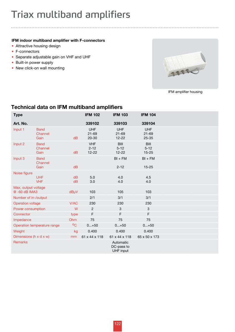
122
Triax multiband amplifiers
IFM indoor multiband amplifier with F-connectors • Attractive housing design • F-connectors• Separate adjustable gain on VHF and UHF• Built-in power supply• New click-on wall mounting
Technical data on IFM multiband amplifiersType
Art. No.
IFM 102
339102
IFM 103
339103
IFM 104
339104Input 1 Band Channel Gain dB
UHF21-6920-30
UHF21-6912-22
UHF21-6925-35
Input 2 Band Channel Gain dB
VHF2-1212-22
BIII5-12
12-22
BIII5-12
15-25
Input 3 Band Channel Gain dB
BI + FM
2-12
BI + FM
15-25
Noise figure UHF VHF
dBdB
5.03.0
4.04.0
4.54.0
Max. output voltage@ -60 dB IMA3 dBµV 103 105 103
Number of in-/output 2/1 3/1 3/1
Operation voltage V/AC 230 230 230
Power consumption W 2 3 3
Connector type F F F
Impedance Ohm 75 75 75
Operation temperature range oC 0...+50 0...+50 0...+50
Weight kg 0.400 0.400 0.400
Dimensions (h x d x w) mm 61 x 44 x 118 61 x 44 x 118 65 x 50 x 173
Remarks AutomaticDC-pass toUHF input
IFM amplifier housing
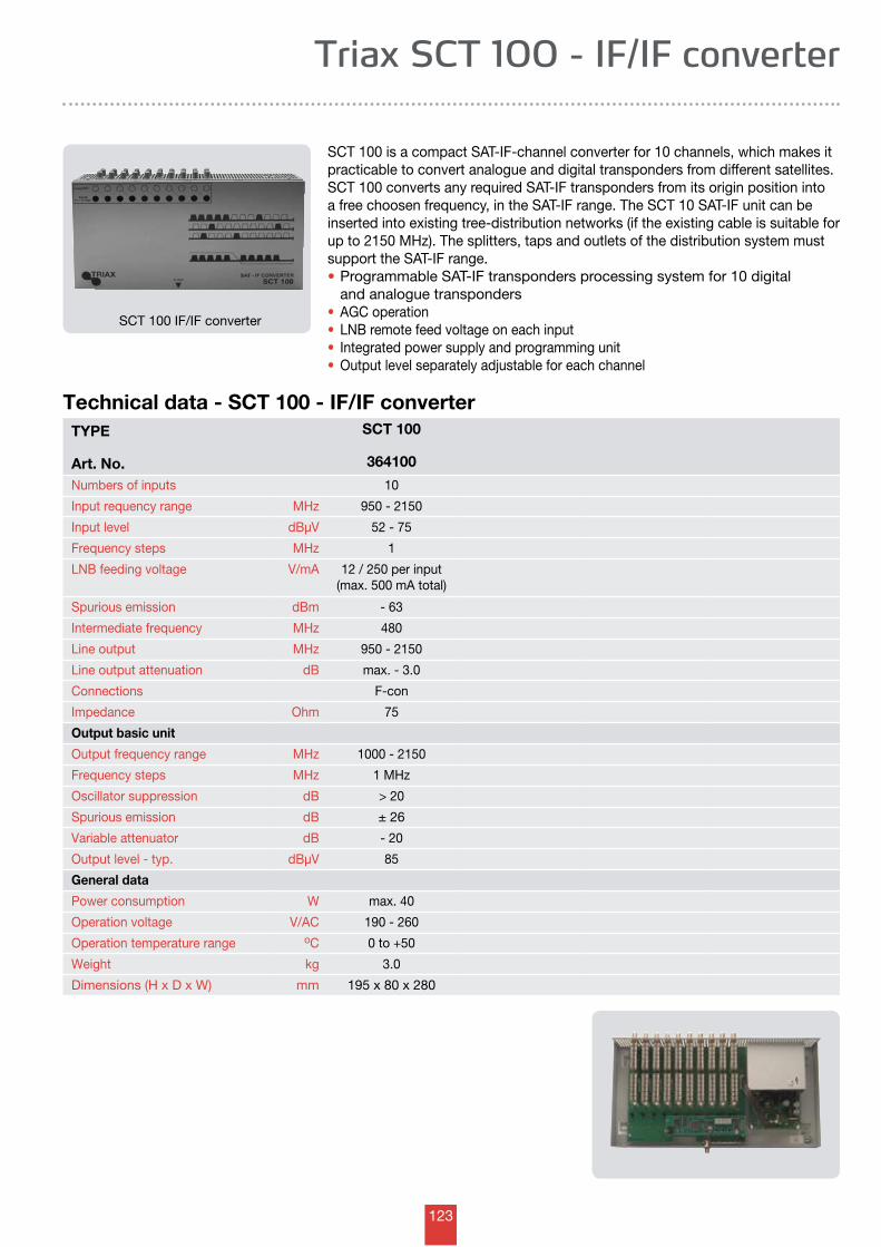
123
TYPE
Art. No.
SCT 100
364100
Numbers of inputs 10
Input requency range MHz 950 - 2150
Input level dBµV 52 - 75
Frequency steps MHz 1
LNB feeding voltage V/mA 12 / 250 per input(max. 500 mA total)
Spurious emission dBm - 63
Intermediate frequency MHz 480
Line output MHz 950 - 2150
Line output attenuation dB max. - 3.0
Connections F-con
Impedance Ohm 75
Output basic unit
Output frequency range MHz 1000 - 2150
Frequency steps MHz 1 MHz
Oscillator suppression dB > 20
Spurious emission dB ± 26
Variable attenuator dB - 20
Output level - typ. dBµV 85
General data
Power consumption W max. 40
Operation voltage V/AC 190 - 260
Operation temperature range oC 0 to +50
Weight kg 3.0
Dimensions (H x D x W) mm 195 x 80 x 280
Technical data - SCT 100 - IF/IF converter
SCT 100 is a compact SAT-IF-channel converter for 10 channels, which makes it practicable to convert analogue and digital transponders from different satellites. SCT 100 converts any required SAT-IF transponders from its origin position into a free choosen frequency, in the SAT-IF range. The SCT 10 SAT-IF unit can be inserted into existing tree-distribution networks (if the existing cable is suitable for up to 2150 MHz). The splitters, taps and outlets of the distribution system must support the SAT-IF range.• Programmable SAT-IF transponders processing system for 10 digital and analogue transponders• AGC operation• LNB remote feed voltage on each input• Integrated power supply and programming unit• Output level separately adjustable for each channel
Triax SCT 100 - IF/IF converter
SCT 100 IF/IF converter
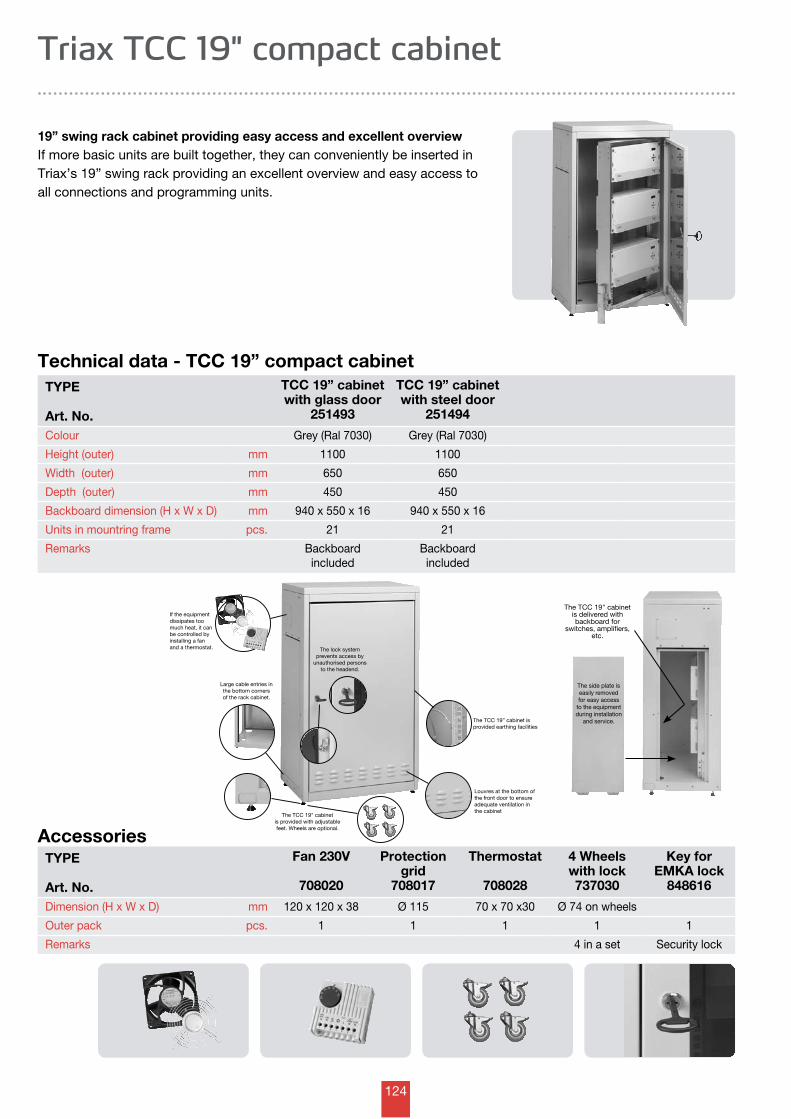
124
If the equipmentdissipates too much heat, it can be controlled by installing a fan and a thermostat.
The TCC 19” cabinet isprovided earthing facilities
Louvres at the bottom of the front door to ensure adequate ventilation in the cabinet
The TCC 19" cabinetis provided with adjustablefeet. Wheels are optional.
Large cable entries inthe bottom cornersof the rack cabinet.
The lock system prevents access by
unauthorised persons to the headend.
The TCC 19" cabinetis delivered with backboard for
switches, amplifiers, etc.
The side plate is easily removed for easy access
to the equipment during installation
and service.
TYPE
Art. No.
TCC 19” cabinetwith glass door
251493
TCC 19” cabinetwith steel door
251494
Colour Grey (Ral 7030) Grey (Ral 7030)
Height (outer) mm 1100 1100
Width (outer) mm 650 650
Depth (outer) mm 450 450
Backboard dimension (H x W x D) mm 940 x 550 x 16 940 x 550 x 16
Units in mountring frame pcs. 21 21
Remarks Backboardincluded
Backboardincluded
Technical data - TCC 19” compact cabinet
19” swing rack cabinet providing easy access and excellent overviewIf more basic units are built together, they can conveniently be inserted in Triax’s 19” swing rack providing an excellent overview and easy access to all connections and programming units.
Triax TCC 19" compact cabinet
TYPE
Art. No.
Fan 230V
708020
Protectiongrid
708017
Thermostat
708028
4 Wheelswith lock737030
Key forEMKA lock
848616
Dimension (H x W x D) mm 120 x 120 x 38 Ø 115 70 x 70 x30 Ø 74 on wheels
Outer pack pcs. 1 1 1 1 1
Remarks 4 in a set Security lock
Accessories
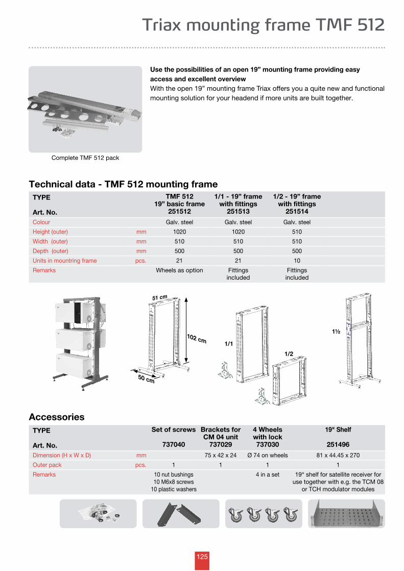
125
1/1
1/2
1½
50 cm
51 cm
102 cm
Technical data - TMF 512 mounting frame
Use the possibilities of an open 19” mounting frame providing easy access and excellent overviewWith the open 19” mounting frame Triax offers you a quite new and functional mounting solution for your headend if more units are built together.
Triax mounting frame TMF 512
Complete TMF 512 pack
TYPE
Art. No.
TMF 512 19” basic frame
251512
1/1 - 19” framewith fittings
251513
1/2 - 19” framewith fittings
251514
Colour Galv. steel Galv. steel Galv. steel
Height (outer) mm 1020 1020 510
Width (outer) mm 510 510 510
Depth (outer) mm 500 500 500
Units in mountring frame pcs. 21 21 10
Remarks Wheels as option Fittingsincluded
Fittingsincluded
TYPE
Art. No.
Set of screws
737040
Brackets forCM 04 unit
737029
4 Wheelswith lock737030
19" Shelf
251496
Dimension (H x W x D) mm 75 x 42 x 24 Ø 74 on wheels 81 x 44.45 x 270
Outer pack pcs. 1 1 1 1
Remarks 10 nut bushings 10 M6x8 screws
10 plastic washers
4 in a set 19“ shelf for satellite receiver for use together with e.g. the TCM 08
or TCH modulator modules
Accessories
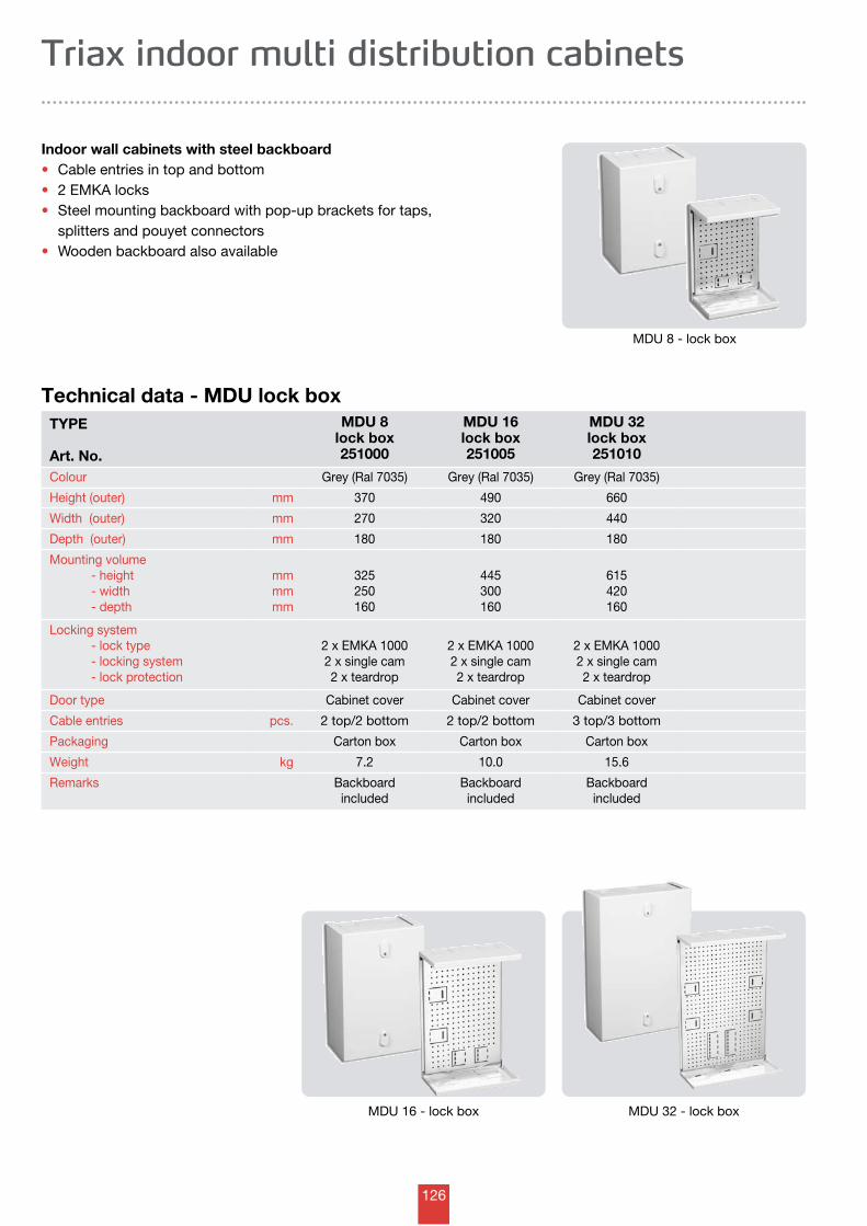
126
TYPE
Art. No.
MDU 8lock box251000
MDU 16lock box251005
MDU 32lock box251010
Colour Grey (Ral 7035) Grey (Ral 7035) Grey (Ral 7035)
Height (outer) mm 370 490 660
Width (outer) mm 270 320 440
Depth (outer) mm 180 180 180
Mounting volume - height - width - depth
mmmmmm
325250160
445300160
615420160
Locking system - lock type - locking system - lock protection
2 x EMKA 10002 x single cam2 x teardrop
2 x EMKA 10002 x single cam2 x teardrop
2 x EMKA 10002 x single cam2 x teardrop
Door type Cabinet cover Cabinet cover Cabinet cover
Cable entries pcs. 2 top/2 bottom 2 top/2 bottom 3 top/3 bottom
Packaging Carton box Carton box Carton box
Weight kg 7.2 10.0 15.6
Remarks Backboardincluded
Backboardincluded
Backboardincluded
Technical data - MDU lock box
Indoor wall cabinets with steel backboard • Cable entries in top and bottom • 2 EMKA locks • Steel mounting backboard with pop-up brackets for taps, splitters and pouyet connectors • Wooden backboard also available
Triax indoor multi distribution cabinets
MDU 8 - lock box
MDU 16 - lock box MDU 32 - lock box
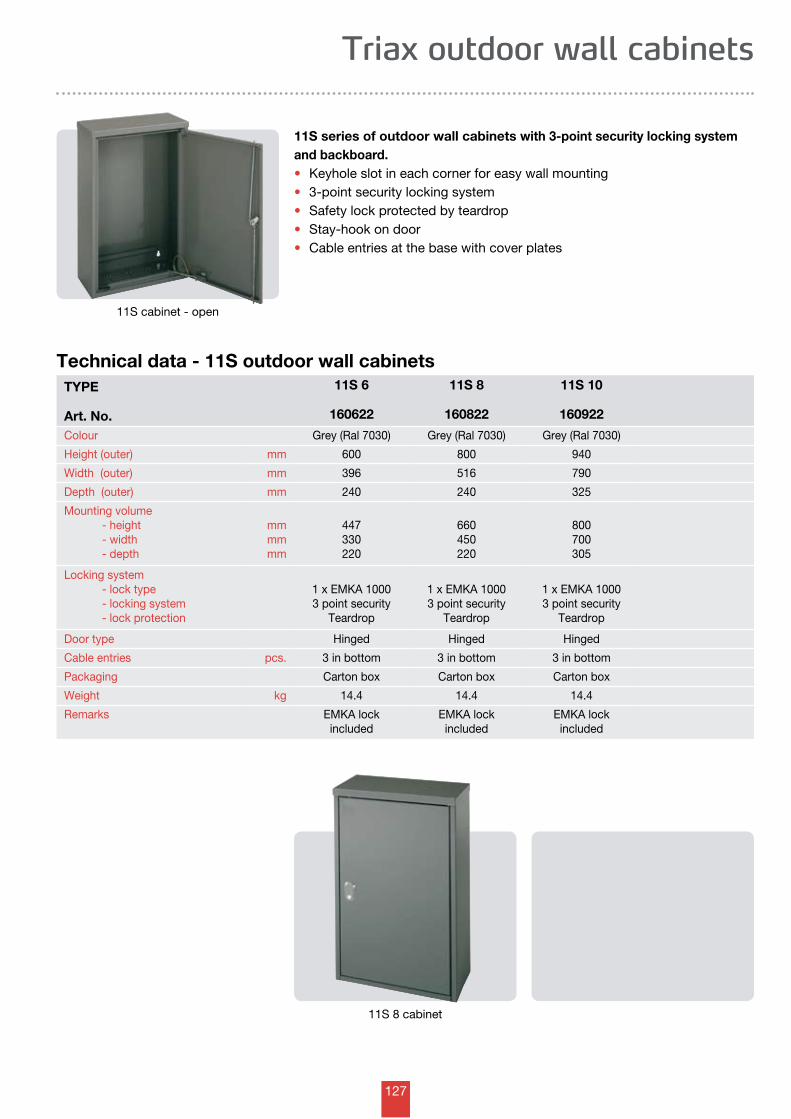
127
Triax outdoor wall cabinets
TYPE
Art. No.
11S 6
160622
11S 8
160822
11S 10
160922
Colour Grey (Ral 7030) Grey (Ral 7030) Grey (Ral 7030)
Height (outer) mm 600 800 940
Width (outer) mm 396 516 790
Depth (outer) mm 240 240 325
Mounting volume - height - width - depth
mmmmmm
447330220
660450220
800700305
Locking system - lock type - locking system - lock protection
1 x EMKA 10003 point security
Teardrop
1 x EMKA 10003 point security
Teardrop
1 x EMKA 10003 point security
Teardrop
Door type Hinged Hinged Hinged
Cable entries pcs. 3 in bottom 3 in bottom 3 in bottom
Packaging Carton box Carton box Carton box
Weight kg 14.4 14.4 14.4
Remarks EMKA lockincluded
EMKA lockincluded
EMKA lockincluded
Technical data - 11S outdoor wall cabinets
11S series of outdoor wall cabinets with 3-point security locking system and backboard. • Keyhole slot in each corner for easy wall mounting • 3-point security locking system • Safety lock protected by teardrop • Stay-hook on door • Cable entries at the base with cover plates
11S cabinet - open
11S 8 cabinet

128
Notes
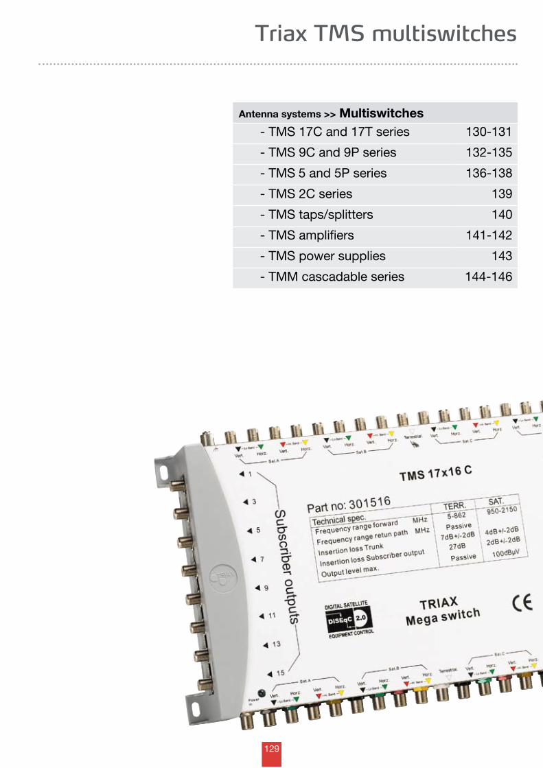
129
Triax TMS multiswitches
Antenna systems >> Multiswitches - TMS 17C and 17T series 130-131
- TMS 9C and 9P series 132-135
- TMS 5 and 5P series 136-138
- TMS 2C series 139
- TMS taps/splitters 140
- TMS amplifiers 141-142
- TMS power supplies 143
- TMM cascadable series 144-146
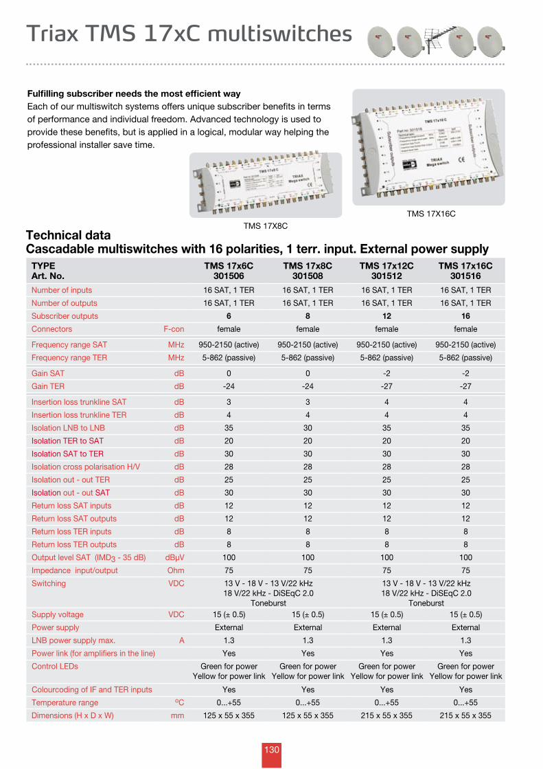
130
TYPEArt. No.
TMS 17x6C301506
TMS 17x8C301508
TMS 17x12C301512
TMS 17x16C301516
Number of inputs 16 SAT, 1 TER 16 SAT, 1 TER 16 SAT, 1 TER 16 SAT, 1 TER
Number of outputs 16 SAT, 1 TER 16 SAT, 1 TER 16 SAT, 1 TER 16 SAT, 1 TER
Subscriber outputs 6 8 12 16
Connectors F-con female female female female
Frequency range SAT MHz 950-2150 (active) 950-2150 (active) 950-2150 (active) 950-2150 (active)
Frequency range TER MHz 5-862 (passive) 5-862 (passive) 5-862 (passive) 5-862 (passive)
Gain SAT dB 0 0 -2 -2
Gain TER dB -24 -24 -27 -27
Insertion loss trunkline SAT dB 3 3 4 4
Insertion loss trunkline TER dB 4 4 4 4
Isolation LNB to LNB dB 35 30 35 35
Isolation TER to SAT dB 20 20 20 20
Isolation SAT to TER dB 30 30 30 30
Isolation cross polarisation H/V dB 28 28 28 28
Isolation out - out TER dB 25 25 25 25
Isolation out - out SAT dB 30 30 30 30
Return loss SAT inputs dB 12 12 12 12
Return loss SAT outputs dB 12 12 12 12
Return loss TER inputs dB 8 8 8 8
Return loss TER outputs dB 8 8 8 8
Output level SAT (IMD3 - 35 dB) dBµV 100 100 100 100
Impedance input/output Ohm 75 75 75 75
Switching VDC 13 V - 18 V - 13 V/22 kHz18 V/22 kHz - DiSEqC 2.0
Toneburst
13 V - 18 V - 13 V/22 kHz18 V/22 kHz - DiSEqC 2.0
ToneburstSupply voltage VDC 15 (± 0.5) 15 (± 0.5) 15 (± 0.5) 15 (± 0.5)
Power supply External External External External
LNB power supply max. A 1.3 1.3 1.3 1.3
Power link (for amplifiers in the line) Yes Yes Yes Yes
Control LEDs Green for powerYellow for power link
Green for powerYellow for power link
Green for powerYellow for power link
Green for powerYellow for power link
Colourcoding of IF and TER inputs Yes Yes Yes Yes
Temperature range oC 0...+55 0...+55 0...+55 0...+55
Dimensions (H x D x W) mm 125 x 55 x 355 125 x 55 x 355 215 x 55 x 355 215 x 55 x 355
Triax TMS 17xC multiswitches
Technical dataCascadable multiswitches with 16 polarities, 1 terr. input. External power supply
Fulfilling subscriber needs the most efficient wayEach of our multiswitch systems offers unique subscriber benefits in terms of performance and individual freedom. Advanced technology is used to provide these benefits, but is applied in a logical, modular way helping the professional installer save time.
TMS 17X8C
TMS 17X16C
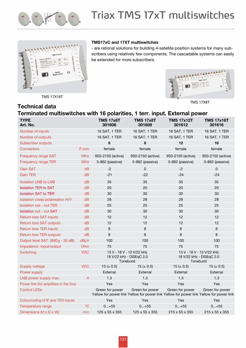
131
Triax TMS 17xT multiswitches
TMS17xC and 17XT multiswitches - are rational solutions for building 4-satellite position systems for many sub-scribers using relatively few components. The cascadable systems can easily be extended for more subscribers.
Technical dataTerminated multiswitches with 16 polarities, 1 terr. input. External power
TYPEArt. No.
TMS 17x6T301606
TMS 17x8T301608
TMS 17x12T301612
TMS 17x16T301616
Number of inputs 16 SAT, 1 TER 16 SAT, 1 TER 16 SAT, 1 TER 16 SAT, 1 TER
Number of outputs 16 SAT, 1 TER 16 SAT, 1 TER 16 SAT, 1 TER 16 SAT, 1 TER
Subscriber outputs 6 8 12 16
Connectors F-con female female female female
Frequency range SAT MHz 950-2150 (active) 950-2150 (active) 950-2150 (active) 950-2150 (active)
Frequency range TER MHz 5-862 (passive) 5-862 (passive) 5-862 (passive) 5-862 (passive)
Gain SAT dB -2 0 -2 0
Gain TER dB -21 -22 -24 -24
Isolation LNB to LNB dB 35 35 35 35
Isolation TER to SAT dB 20 20 20 20
Isolation SAT to TER dB 30 30 30 30
Isolation cross polarisation H/V dB 28 28 28 28
Isolation out - out TER dB 25 25 25 25
Isolation out - out SAT dB 30 30 30 30
Return loss SAT inputs dB 12 12 12 12
Return loss SAT outputs dB 12 12 12 12
Return loss TER inputs dB 8 8 8 8
Return loss TER outputs dB 8 8 8 8
Output level SAT (IMD3 - 35 dB) dBµV 100 100 100 100
Impedance input/output Ohm 75 75 75 75
Switching VDC 13 V - 18 V - 13 V/22 kHz18 V/22 kHz - DiSEqC 2.0
Toneburst
13 V - 18 V - 13 V/22 kHz18 V/22 kHz - DiSEqC 2.0
ToneburstSupply voltage VDC 15 (± 0.5) 15 (± 0.5) 15 (± 0.5) 15 (± 0.5)
Power supply External External External External
LNB power supply max. A 1.3 1.3 1.3 1.3
Power link (for amplifiers in the line) Yes Yes Yes Yes
Control LEDs Green for powerYellow for power link
Green for powerYellow for power link
Green for powerYellow for power link
Green for powerYellow for power link
Colourcoding of IF and TER inputs Yes Yes Yes Yes
Temperature range oC 0...+55 0...+55 0...+55 0...+55
Dimensions (H x D x W) mm 125 x 55 x 355 125 x 55 x 355 215 x 55 x 355 215 x 55 x 355
TMS 17X16T
TMS 17X8T
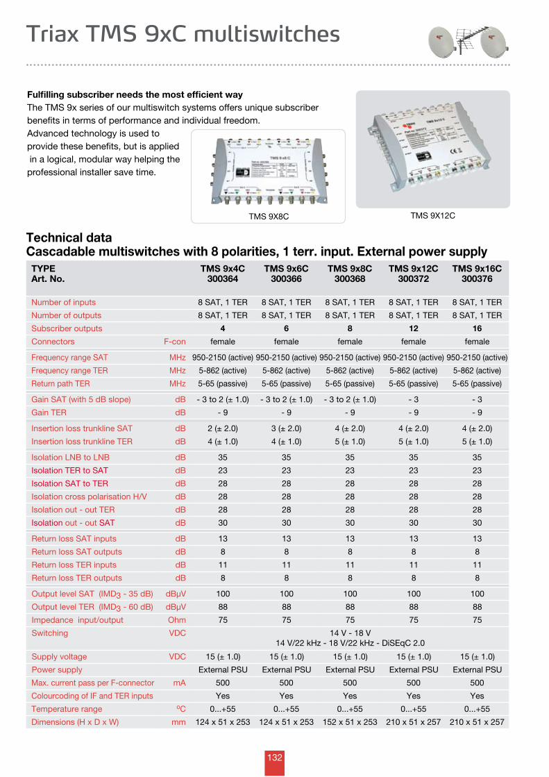
132
TYPEArt. No.
TMS 9x4C300364
TMS 9x6C300366
TMS 9x8C300368
TMS 9x12C300372
TMS 9x16C300376
Number of inputs 8 SAT, 1 TER 8 SAT, 1 TER 8 SAT, 1 TER 8 SAT, 1 TER 8 SAT, 1 TER
Number of outputs 8 SAT, 1 TER 8 SAT, 1 TER 8 SAT, 1 TER 8 SAT, 1 TER 8 SAT, 1 TER
Subscriber outputs 4 6 8 12 16
Connectors F-con female female female female female
Frequency range SAT MHz 950-2150 (active) 950-2150 (active) 950-2150 (active) 950-2150 (active) 950-2150 (active)
Frequency range TER MHz 5-862 (active) 5-862 (active) 5-862 (active) 5-862 (active) 5-862 (active)
Return path TER MHz 5-65 (passive) 5-65 (passive) 5-65 (passive) 5-65 (passive) 5-65 (passive)
Gain SAT (with 5 dB slope) dB - 3 to 2 (± 1.0) - 3 to 2 (± 1.0) - 3 to 2 (± 1.0) - 3 - 3
Gain TER dB - 9 - 9 - 9 - 9 - 9
Insertion loss trunkline SAT dB 2 (± 2.0) 3 (± 2.0) 4 (± 2.0) 4 (± 2.0) 4 (± 2.0)
Insertion loss trunkline TER dB 4 (± 1.0) 4 (± 1.0) 5 (± 1.0) 5 (± 1.0) 5 (± 1.0)
Isolation LNB to LNB dB 35 35 35 35 35
Isolation TER to SAT dB 23 23 23 23 23
Isolation SAT to TER dB 28 28 28 28 28
Isolation cross polarisation H/V dB 28 28 28 28 28
Isolation out - out TER dB 28 28 28 28 28
Isolation out - out SAT dB 30 30 30 30 30
Return loss SAT inputs dB 13 13 13 13 13
Return loss SAT outputs dB 8 8 8 8 8
Return loss TER inputs dB 11 11 11 11 11
Return loss TER outputs dB 8 8 8 8 8
Output level SAT (IMD3 - 35 dB) dBµV 100 100 100 100 100
Output level TER (IMD3 - 60 dB) dBµV 88 88 88 88 88
Impedance input/output Ohm 75 75 75 75 75
Switching VDC 14 V - 18 V14 V/22 kHz - 18 V/22 kHz - DiSEqC 2.0
Supply voltage VDC 15 (± 1.0) 15 (± 1.0) 15 (± 1.0) 15 (± 1.0) 15 (± 1.0)
Power supply External PSU External PSU External PSU External PSU External PSU
Max. current pass per F-connector mA 500 500 500 500 500
Colourcoding of IF and TER inputs Yes Yes Yes Yes Yes
Temperature range oC 0...+55 0...+55 0...+55 0...+55 0...+55
Dimensions (H x D x W) mm 124 x 51 x 253 124 x 51 x 253 152 x 51 x 253 210 x 51 x 257 210 x 51 x 257
Triax TMS 9xC multiswitches
Technical dataCascadable multiswitches with 8 polarities, 1 terr. input. External power supply
Fulfilling subscriber needs the most efficient wayThe TMS 9x series of our multiswitch systems offers unique subscriber benefits in terms of performance and individual freedom. Advanced technology is used to provide these benefits, but is applied in a logical, modular way helping the professional installer save time.
TMS 9X8C TMS 9X12C
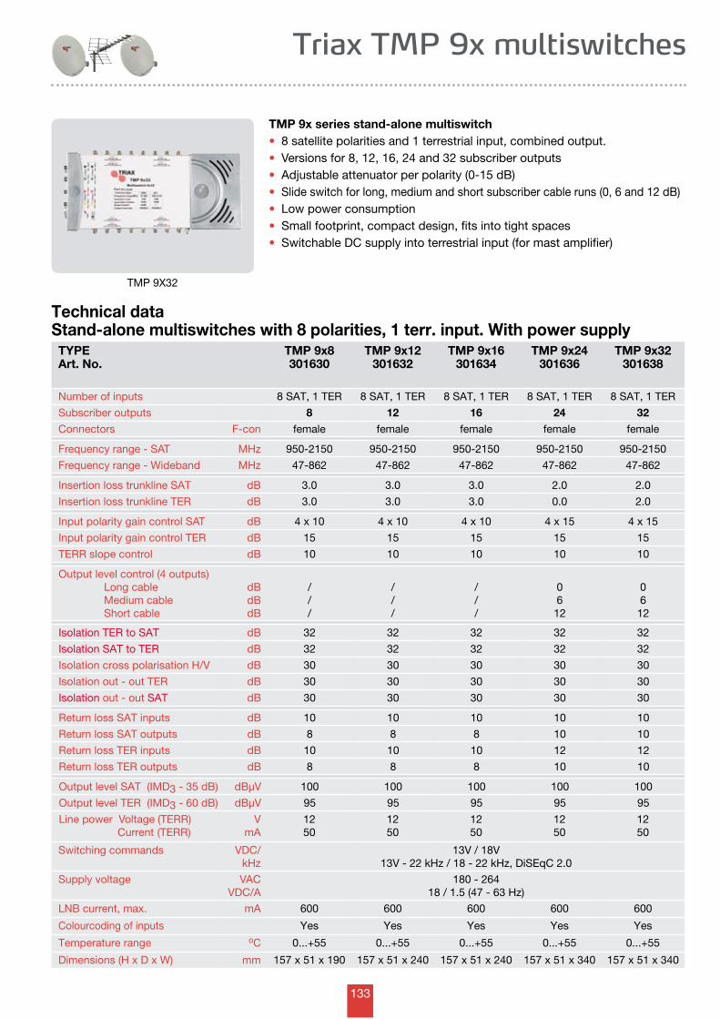
133
Triax TMP 9x multiswitches
TMP 9x series stand-alone multiswitch• 8 satellite polarities and 1 terrestrial input, combined output.• Versions for 8, 12, 16, 24 and 32 subscriber outputs• Adjustable attenuator per polarity (0-15 dB)• Slide switch for long, medium and short subscriber cable runs (0, 6 and 12 dB)• Low power consumption • Small footprint, compact design, fits into tight spaces• Switchable DC supply into terrestrial input (for mast amplifier)
TMP 9X32
Technical dataStand-alone multiswitches with 8 polarities, 1 terr. input. With power supply
TYPEArt. No.
TMP 9x8301630
TMP 9x12301632
TMP 9x16301634
TMP 9x24301636
TMP 9x32301638
Number of inputs 8 SAT, 1 TER 8 SAT, 1 TER 8 SAT, 1 TER 8 SAT, 1 TER 8 SAT, 1 TER
Subscriber outputs 8 12 16 24 32
Connectors F-con female female female female female
Frequency range - SAT MHz 950-2150 950-2150 950-2150 950-2150 950-2150
Frequency range - Wideband MHz 47-862 47-862 47-862 47-862 47-862
Insertion loss trunkline SAT dB 3.0 3.0 3.0 2.0 2.0
Insertion loss trunkline TER dB 3.0 3.0 3.0 0.0 2.0
Input polarity gain control SAT dB 4 x 10 4 x 10 4 x 10 4 x 15 4 x 15
Input polarity gain control TER dB 15 15 15 15 15
TERR slope control dB 10 10 10 10 10
Output level control (4 outputs) Long cable Medium cable Short cable
dBdBdB
///
///
///
06
12
06
12
Isolation TER to SAT dB 32 32 32 32 32
Isolation SAT to TER dB 32 32 32 32 32
Isolation cross polarisation H/V dB 30 30 30 30 30
Isolation out - out TER dB 30 30 30 30 30
Isolation out - out SAT dB 30 30 30 30 30
Return loss SAT inputs dB 10 10 10 10 10
Return loss SAT outputs dB 8 8 8 10 10
Return loss TER inputs dB 10 10 10 12 12
Return loss TER outputs dB 8 8 8 10 10
Output level SAT (IMD3 - 35 dB) dBµV 100 100 100 100 100
Output level TER (IMD3 - 60 dB) dBµV 95 95 95 95 95
Line power Voltage (TERR) Current (TERR)
VmA
1250
1250
1250
1250
1250
Switching commands VDC/kHz
13V / 18V13V - 22 kHz / 18 - 22 kHz, DiSEqC 2.0
Supply voltage VACVDC/A
180 - 26418 / 1.5 (47 - 63 Hz)
LNB current, max. mA 600 600 600 600 600
Colourcoding of inputs Yes Yes Yes Yes Yes
Temperature range oC 0...+55 0...+55 0...+55 0...+55 0...+55
Dimensions (H x D x W) mm 157 x 51 x 190 157 x 51 x 240 157 x 51 x 240 157 x 51 x 340 157 x 51 x 340
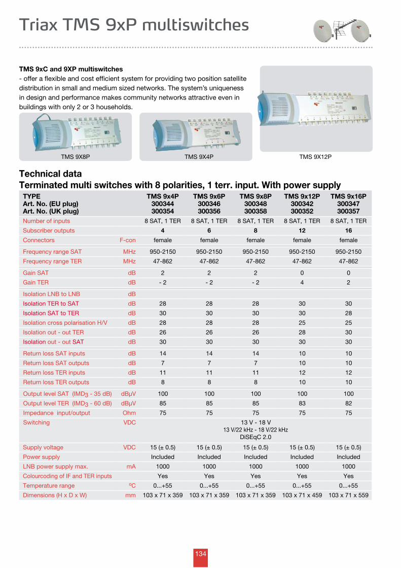
134
TYPEArt. No. (EU plug)Art. No. (UK plug)
TMS 9x4P300344300354
TMS 9x6P300346300356
TMS 9x8P300348300358
TMS 9x12P300342300352
TMS 9x16P300347300357
Number of inputs 8 SAT, 1 TER 8 SAT, 1 TER 8 SAT, 1 TER 8 SAT, 1 TER 8 SAT, 1 TER
Subscriber outputs 4 6 8 12 16
Connectors F-con female female female female female
Frequency range SAT MHz 950-2150 950-2150 950-2150 950-2150 950-2150
Frequency range TER MHz 47-862 47-862 47-862 47-862 47-862
Gain SAT dB 2 2 2 0 0
Gain TER dB - 2 - 2 - 2 4 2
Isolation LNB to LNB dB
Isolation TER to SAT dB 28 28 28 30 30
Isolation SAT to TER dB 30 30 30 30 28
Isolation cross polarisation H/V dB 28 28 28 25 25
Isolation out - out TER dB 26 26 26 28 30
Isolation out - out SAT dB 30 30 30 30 30
Return loss SAT inputs dB 14 14 14 10 10
Return loss SAT outputs dB 7 7 7 10 10
Return loss TER inputs dB 11 11 11 12 12
Return loss TER outputs dB 8 8 8 10 10
Output level SAT (IMD3 - 35 dB) dBµV 100 100 100 100 100
Output level TER (IMD3 - 60 dB) dBµV 85 85 85 83 82
Impedance input/output Ohm 75 75 75 75 75
Switching VDC 13 V - 18 V13 V/22 kHz - 18 V/22 kHz
DiSEqC 2.0
Supply voltage VDC 15 (± 0.5) 15 (± 0.5) 15 (± 0.5) 15 (± 0.5) 15 (± 0.5)
Power supply Included Included Included Included Included
LNB power supply max. mA 1000 1000 1000 1000 1000
Colourcoding of IF and TER inputs Yes Yes Yes Yes Yes
Temperature range oC 0...+55 0...+55 0...+55 0...+55 0...+55
Dimensions (H x D x W) mm 103 x 71 x 359 103 x 71 x 359 103 x 71 x 359 103 x 71 x 459 103 x 71 x 559
Triax TMS 9xP multiswitches
TMS 9xC and 9XP multiswitches - offer a flexible and cost efficient system for providing two position satellite distribution in small and medium sized networks. The system’s uniqueness in design and performance makes community networks attractive even in buildings with only 2 or 3 households.
Technical dataTerminated multi switches with 8 polarities, 1 terr. input. With power supply
TMS 9X8P TMS 9X4P TMS 9X12P
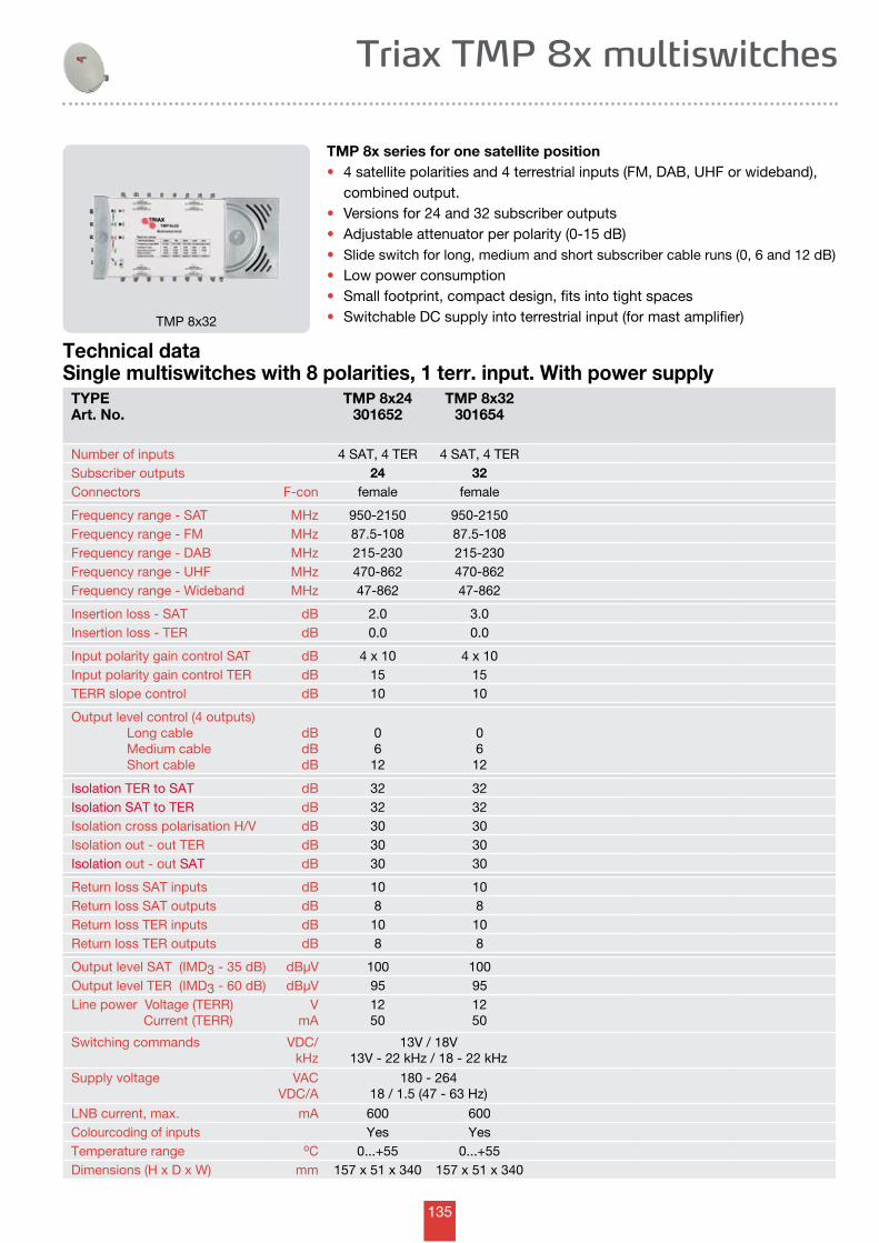
135
Triax TMP 8x multiswitches
TMP 8x32
TMP 8x series for one satellite position• 4 satellite polarities and 4 terrestrial inputs (FM, DAB, UHF or wideband), combined output.• Versions for 24 and 32 subscriber outputs• Adjustable attenuator per polarity (0-15 dB)• Slide switch for long, medium and short subscriber cable runs (0, 6 and 12 dB)
• Low power consumption • Small footprint, compact design, fits into tight spaces• Switchable DC supply into terrestrial input (for mast amplifier)
Technical dataSingle multiswitches with 8 polarities, 1 terr. input. With power supply
TYPEArt. No.
TMP 8x24301652
TMP 8x32301654
Number of inputs 4 SAT, 4 TER 4 SAT, 4 TERSubscriber outputs 24 32Connectors F-con female female
Frequency range - SAT MHz 950-2150 950-2150Frequency range - FM MHz 87.5-108 87.5-108Frequency range - DAB MHz 215-230 215-230Frequency range - UHF MHz 470-862 470-862Frequency range - Wideband MHz 47-862 47-862
Insertion loss - SAT dB 2.0 3.0Insertion loss - TER dB 0.0 0.0
Input polarity gain control SAT dB 4 x 10 4 x 10Input polarity gain control TER dB 15 15TERR slope control dB 10 10
Output level control (4 outputs) Long cable Medium cable Short cable
dBdBdB
0612
06
12
Isolation TER to SAT dB 32 32Isolation SAT to TER dB 32 32Isolation cross polarisation H/V dB 30 30Isolation out - out TER dB 30 30Isolation out - out SAT dB 30 30
Return loss SAT inputs dB 10 10Return loss SAT outputs dB 8 8Return loss TER inputs dB 10 10Return loss TER outputs dB 8 8
Output level SAT (IMD3 - 35 dB) dBµV 100 100Output level TER (IMD3 - 60 dB) dBµV 95 95Line power Voltage (TERR) Current (TERR)
VmA
1250
1250
Switching commands VDC/kHz
13V / 18V13V - 22 kHz / 18 - 22 kHz
Supply voltage VACVDC/A
180 - 26418 / 1.5 (47 - 63 Hz)
LNB current, max. mA 600 600Colourcoding of inputs Yes YesTemperature range oC 0...+55 0...+55Dimensions (H x D x W) mm 157 x 51 x 340 157 x 51 x 340
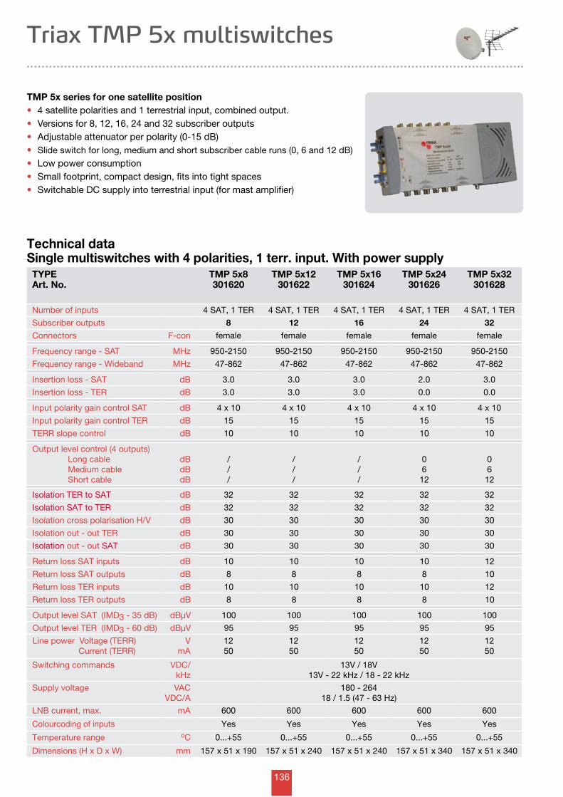
136
Triax TMP 5x multiswitches
TMP 5x series for one satellite position• 4 satellite polarities and 1 terrestrial input, combined output.• Versions for 8, 12, 16, 24 and 32 subscriber outputs• Adjustable attenuator per polarity (0-15 dB)• Slide switch for long, medium and short subscriber cable runs (0, 6 and 12 dB)
• Low power consumption • Small footprint, compact design, fits into tight spaces• Switchable DC supply into terrestrial input (for mast amplifier)
Technical dataSingle multiswitches with 4 polarities, 1 terr. input. With power supply
TYPEArt. No.
TMP 5x8301620
TMP 5x12301622
TMP 5x16301624
TMP 5x24301626
TMP 5x32301628
Number of inputs 4 SAT, 1 TER 4 SAT, 1 TER 4 SAT, 1 TER 4 SAT, 1 TER 4 SAT, 1 TER
Subscriber outputs 8 12 16 24 32
Connectors F-con female female female female female
Frequency range - SAT MHz 950-2150 950-2150 950-2150 950-2150 950-2150
Frequency range - Wideband MHz 47-862 47-862 47-862 47-862 47-862
Insertion loss - SAT dB 3.0 3.0 3.0 2.0 3.0
Insertion loss - TER dB 3.0 3.0 3.0 0.0 0.0
Input polarity gain control SAT dB 4 x 10 4 x 10 4 x 10 4 x 10 4 x 10
Input polarity gain control TER dB 15 15 15 15 15
TERR slope control dB 10 10 10 10 10
Output level control (4 outputs) Long cable Medium cable Short cable
dBdBdB
///
///
///
06
12
06
12
Isolation TER to SAT dB 32 32 32 32 32
Isolation SAT to TER dB 32 32 32 32 32
Isolation cross polarisation H/V dB 30 30 30 30 30
Isolation out - out TER dB 30 30 30 30 30
Isolation out - out SAT dB 30 30 30 30 30
Return loss SAT inputs dB 10 10 10 10 12
Return loss SAT outputs dB 8 8 8 8 10
Return loss TER inputs dB 10 10 10 10 12
Return loss TER outputs dB 8 8 8 8 10
Output level SAT (IMD3 - 35 dB) dBµV 100 100 100 100 100
Output level TER (IMD3 - 60 dB) dBµV 95 95 95 95 95
Line power Voltage (TERR) Current (TERR)
VmA
1250
1250
1250
1250
1250
Switching commands VDC/kHz
13V / 18V13V - 22 kHz / 18 - 22 kHz
Supply voltage VACVDC/A
180 - 26418 / 1.5 (47 - 63 Hz)
LNB current, max. mA 600 600 600 600 600
Colourcoding of inputs Yes Yes Yes Yes Yes
Temperature range oC 0...+55 0...+55 0...+55 0...+55 0...+55
Dimensions (H x D x W) mm 157 x 51 x 190 157 x 51 x 240 157 x 51 x 240 157 x 51 x 340 157 x 51 x 340
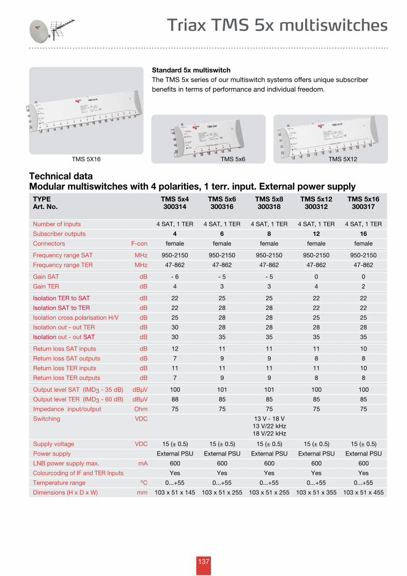
137
TYPEArt. No.
TMS 5x4300314
TMS 5x6300316
TMS 5x8300318
TMS 5x12300312
TMS 5x16300317
Number of inputs 4 SAT, 1 TER 4 SAT, 1 TER 4 SAT, 1 TER 4 SAT, 1 TER 4 SAT, 1 TER
Subscriber outputs 4 6 8 12 16
Connectors F-con female female female female female
Frequency range SAT MHz 950-2150 950-2150 950-2150 950-2150 950-2150
Frequency range TER MHz 47-862 47-862 47-862 47-862 47-862
Gain SAT dB - 6 - 5 - 5 0 0
Gain TER dB 4 3 3 4 2
Isolation TER to SAT dB 22 25 25 22 22
Isolation SAT to TER dB 22 28 28 22 22
Isolation cross polarisation H/V dB 25 28 28 25 25
Isolation out - out TER dB 30 28 28 28 28
Isolation out - out SAT dB 30 35 35 35 35
Return loss SAT inputs dB 12 11 11 11 10
Return loss SAT outputs dB 7 9 9 8 8
Return loss TER inputs dB 11 11 11 11 10
Return loss TER outputs dB 7 9 9 8 8
Output level SAT (IMD3 - 35 dB) dBµV 100 101 101 100 100
Output level TER (IMD3 - 60 dB) dBµV 88 85 85 85 85
Impedance input/output Ohm 75 75 75 75 75
Switching VDC 13 V - 18 V13 V/22 kHz18 V/22 kHz
Supply voltage VDC 15 (± 0.5) 15 (± 0.5) 15 (± 0.5) 15 (± 0.5) 15 (± 0.5)
Power supply External PSU External PSU External PSU External PSU External PSU
LNB power supply max. mA 600 600 600 600 600
Colourcoding of IF and TER Inputs Yes Yes Yes Yes Yes
Temperature range oC 0...+55 0...+55 0...+55 0...+55 0...+55
Dimensions (H x D x W) mm 103 x 51 x 145 103 x 51 x 255 103 x 51 x 255 103 x 51 x 355 103 x 51 x 455
Triax TMS 5x multiswitches
Technical dataModular multiswitches with 4 polarities, 1 terr. input. External power supply
Standard 5x multiswitchThe TMS 5x series of our multiswitch systems offers unique subscriber benefits in terms of performance and individual freedom.
TMS 5x6 TMS 5X12TMS 5X16
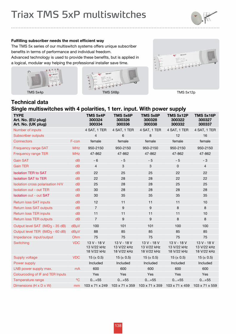
138
TYPEArt. No. (EU plug)Art. No. (UK plug)
TMS 5x4P300324300334
TMS 5x6P300326300336
TMS 5x8P300328300338
TMS 5x12P300322300332
TMS 5x16P300327300337
Number of inputs 4 SAT, 1 TER 4 SAT, 1 TER 4 SAT, 1 TER 4 SAT, 1 TER 4 SAT, 1 TER
Subscriber outputs 4 6 8 12 16
Connectors F-con female female female female female
Frequency range SAT MHz 950-2150 950-2150 950-2150 950-2150 950-2150
Frequency range TER MHz 47-862 47-862 47-862 47-862 47-862
Gain SAT dB - 6 - 5 - 5 - 5 - 3
Gain TER dB 4 3 3 0 4
Isolation TER to SAT dB 22 25 25 22 22
Isolation SAT to TER dB 22 28 28 22 22
Isolation cross polarisation H/V dB 25 28 28 25 25
Isolation out - out TER dB 30 28 28 28 28
Isolation out - out SAT dB 30 35 35 35 35
Return loss SAT inputs dB 12 11 11 11 10
Return loss SAT outputs dB 7 9 9 8 8
Return loss TER inputs dB 11 11 11 11 10
Return loss TER outputs dB 7 9 9 8 8
Output level SAT (IMD3 - 35 dB) dBµV 100 101 101 100 100
Output level TER (IMD3 - 60 dB) dBµV 88 85 85 85 85
Impedance input/output Ohm 75 75 75 75 75
Switching VDC 13 V - 18 V13 V/22 kHz18 V/22 kHz
13 V - 18 V13 V/22 kHz18 V/22 kHz
13 V - 18 V13 V/22 kHz18 V/22 kHz
13 V - 18 V13 V/22 kHz18 V/22 kHz
13 V - 18 V13 V/22 kHz18 V/22 kHz
Supply voltage VDC 15 (± 0.5) 15 (± 0.5) 15 (± 0.5) 15 (± 0.5) 15 (± 0.5)
Power supply Included Included Included Included Included
LNB power supply max. mA 600 600 600 600 600
Colourcoding of IF and TER Inputs Yes Yes Yes Yes Yes
Temperature range oC 0...+55 0...+55 0...+55 0...+55 0...+55
Dimensions (H x D x W) mm 103 x 71 x 249 103 x 71 x 359 103 x 71 x 359 103 x 71 x 459 103 x 71 x 559
Triax TMS 5xP multiswitches
Fulfilling subscriber needs the most efficient wayThe TMS 5x series of our multiswitch systems offers unique subscriber benefits in terms of performance and individual freedom. Advanced technology is used to provide these benefits, but is applied in a logical, modular way helping the professional installer save time.
Technical dataSingle multiswitches with 4 polarities, 1 terr. input. With power supply
TMS 5X8pTMS 5x4p TMS 5x12p
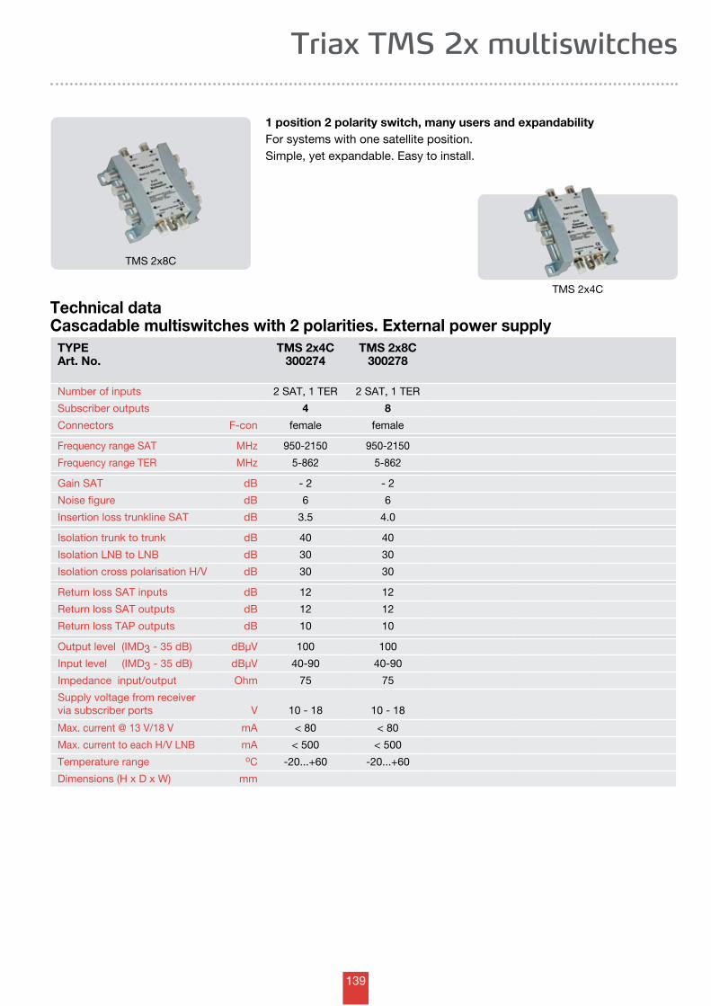
139
Triax TMS 2x multiswitches
Technical dataCascadable multiswitches with 2 polarities. External power supply
1 position 2 polarity switch, many users and expandabilityFor systems with one satellite position.Simple, yet expandable. Easy to install.
TMS 2x4C
TMS 2x8C
TYPEArt. No.
TMS 2x4C300274
TMS 2x8C300278
Number of inputs 2 SAT, 1 TER 2 SAT, 1 TER
Subscriber outputs 4 8
Connectors F-con female female
Frequency range SAT MHz 950-2150 950-2150
Frequency range TER MHz 5-862 5-862
Gain SAT dB - 2 - 2
Noise figure dB 6 6
Insertion loss trunkline SAT dB 3.5 4.0
Isolation trunk to trunk dB 40 40
Isolation LNB to LNB dB 30 30
Isolation cross polarisation H/V dB 30 30
Return loss SAT inputs dB 12 12
Return loss SAT outputs dB 12 12
Return loss TAP outputs dB 10 10
Output level (IMD3 - 35 dB) dBµV 100 100
Input level (IMD3 - 35 dB) dBµV 40-90 40-90
Impedance input/output Ohm 75 75
Supply voltage from receivervia subscriber ports V 10 - 18 10 - 18
Max. current @ 13 V/18 V mA < 80 < 80
Max. current to each H/V LNB mA < 500 < 500
Temperature range oC -20...+60 -20...+60
Dimensions (H x D x W) mm
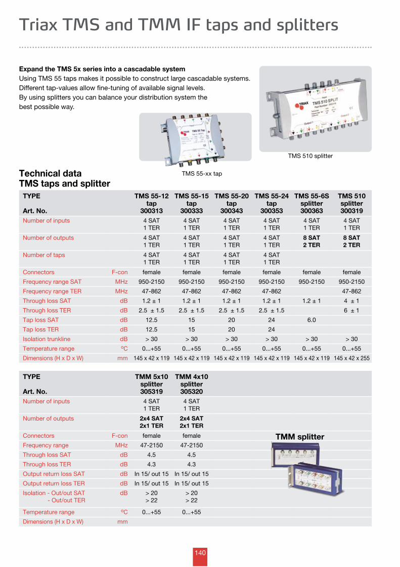
140
Technical dataTMS taps and splitter
Triax TMS and TMM IF taps and splitters
Expand the TMS 5x series into a cascadable systemUsing TMS 55 taps makes it possible to construct large cascadable systems. Different tap-values allow fine-tuning of available signal levels.By using splitters you can balance your distribution system the best possible way.
TYPE
Art. No.
TMS 55-12 tap
300313
TMS 55-15 tap
300333
TMS 55-20 tap
300343
TMS 55-24 tap
300353
TMS 55-6Ssplitter300363
TMS 510 splitter300319
Number of inputs 4 SAT1 TER
4 SAT1 TER
4 SAT1 TER
4 SAT1 TER
4 SAT1 TER
4 SAT1 TER
Number of outputs 4 SAT1 TER
4 SAT1 TER
4 SAT1 TER
4 SAT1 TER
8 SAT2 TER
8 SAT2 TER
Number of taps 4 SAT1 TER
4 SAT1 TER
4 SAT1 TER
4 SAT1 TER
Connectors F-con female female female female female female
Frequency range SAT MHz 950-2150 950-2150 950-2150 950-2150 950-2150 950-2150
Frequency range TER MHz 47-862 47-862 47-862 47-862 47-862
Through loss SAT dB 1.2 ± 1 1.2 ± 1 1.2 ± 1 1.2 ± 1 1.2 ± 1 4 ± 1
Through loss TER dB 2.5 ± 1.5 2.5 ± 1.5 2.5 ± 1.5 2.5 ± 1.5 6 ± 1
Tap loss SAT dB 12.5 15 20 24 6.0
Tap loss TER dB 12.5 15 20 24
Isolation trunkline dB > 30 > 30 > 30 > 30 > 30 > 30
Temperature range oC 0...+55 0...+55 0...+55 0...+55 0...+55 0...+55
Dimensions (H x D x W) mm 145 x 42 x 119 145 x 42 x 119 145 x 42 x 119 145 x 42 x 119 145 x 42 x 119 145 x 42 x 255
TMS 55-xx tap
TMS 510 splitter
TYPE
Art. No.
TMM 5x10splitter305319
TMM 4x10splitter305320
Number of inputs 4 SAT1 TER
4 SAT1 TER
Number of outputs 2x4 SAT2x1 TER
2x4 SAT2x1 TER
Connectors F-con female female
Frequency range MHz 47-2150 47-2150
Through loss SAT dB 4.5 4.5
Through loss TER dB 4.3 4.3
Output return loss SAT dB In 15/ out 15 In 15/ out 15
Output return loss TER dB In 15/ out 15 In 15/ out 15
Isolation - Out/out SAT - Out/out TER
dB > 20> 22
> 20> 22
Temperature range oC 0...+55 0...+55
Dimensions (H x D x W) mm
TMM splitter
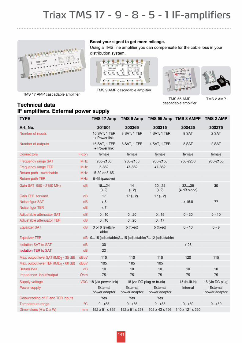
141
TYPE
Art. No.
TMS 17 Amp
301501
TMS 9 Amp
300365
TMS 55 Amp
300315
TMS 8 AMPP
300425
TMS 2 AMP
300275Number of inputs 16 SAT, 1 TER
+ Power link8 SAT, 1 TER 4 SAT, 1 TER 8 SAT 2 SAT
Number of outputs 16 SAT, 1 TER+ Power link
8 SAT, 1 TER 4 SAT, 1 TER 8 SAT 2 SAT
Connectors F-con female female female female female
Frequency range SAT MHz 950-2150 950-2150 950-2150 950-2200 950-2150
Frequency range TER MHz 5-862 47-862 47-862
Return path - switchable MHz 5-30 or 5-65
Return path TER MHz 5-65 (passive)
Gain SAT 950 - 2150 MHz dB 18....24 (± 2)
14 (± 2)
20...25 (± 2)
32....36 (4 dB slope)
30
Gain TER forward dB 17 17 (± 2) 17 (± 2)
Noise figur SAT dB < 8 < 16.0 ??
Noise figur TER dB < 7
Adjustable attenuator SAT dB 0...10 0...20 0...15 0 - 20 0 - 10
Adjustable attenuator TER dB 0...10 0...20 0...17
Equalizer SAT dB 0 or 6 (switch-able)
5 (fixed) 5 (fixed) 0 - 10 0 - 8
Equalizer TER dB 0...15 (adjustable) 2...15 (adjustable) 7...12 (adjustable)
Isolation SAT to SAT dB 30 > 25
Isolation TER to SAT dB 22
Max. output level SAT (IMD3 - 35 dB) dBµV 110 110 110 120 115
Max. output level TER (IMD3 - 60 dB) dBµV 105 105 105
Return loss dB 10 10 10 10 10
Impedance input/output Ohm 75 75 75 75 75
Supply voltage VDC 18 (via power link) 18 (via DC plug or trunk) 15 (built in) 18 (via DC plug)
Power supply External power adaptor
External power adaptor
External power adaptor
Internal External power adaptor
Colourcoding of IF and TER inputs Yes Yes Yes
Temperature range oC 0...+55 0...+55 0...+55 0...+50 0...+50
Dimensions (H x D x W) mm 152 x 51 x 355 152 x 51 x 253 105 x 43 x 196 140 x 121 x 250
Technical dataIF amplifiers. External power supply
Triax TMS 17 - 9 - 8 - 5 - 1 IF-amplifiers
Boost your signal to get more mileage.Using a TMS line amplifier you can compensate for the cable loss in yourdistribution system.
TMS 9 AMP cascadable amplifier
TMS 55 AMP cascadable amplifier
TMS 17 AMP cascadable amplifierTMS 2 AMP
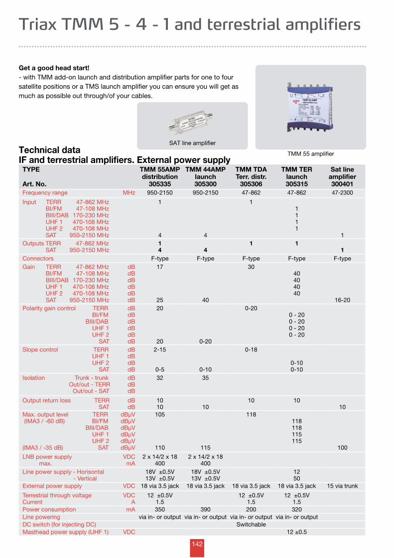
142
Technical dataIF and terrestrial amplifiers. External power supply
Triax TMM 5 - 4 - 1 and terrestrial amplifiers
Get a good head start!- with TMM add-on launch and distribution amplifier parts for one to four satellite positions or a TMS launch amplifier you can ensure you will get as much as possible out through/of your cables.
SAT line amplifier
TYPE
Art. No.
TMM 55AMPdistribution
305335
TMM 44AMPlaunch305300
TMM TDATerr. distr.
305306
TMM TERlaunch305315
Sat line amplifier300401
Frequency range MHz 950-2150 950-2150 47-862 47-862 47-2300
Input TERR 47-862 MHz BI/FM 47-108 MHz BIII/DAB 170-230 MHz UHF 1 470-108 MHz UHF 2 470-108 MHz SAT 950-2150 MHz
1
4 4
11111
1Outputs TERR 47-862 MHz SAT 950-2150 MHz
14 4
1 11
Connectors F-type F-type F-type F-type F-typeGain TERR 47-862 MHz BI/FM 47-108 MHz BIII/DAB 170-230 MHz UHF 1 470-108 MHz UHF 2 470-108 MHz SAT 950-2150 MHz
dBdBdBdBdBdB
17
25 40
3040404040
16-20Polarity gain control TERR BI/FM BIII/DAB UHF 1 UHF 2 SAT
dBdBdBdBdBdB
20
20 0-20
0-200 - 200 - 200 - 200 - 20
Slope control TERR UHF 1 UHF 2 SAT
dBdBdBdB
2-15
0-5 0-10
0-18
0-100-10
Isolation Trunk - trunk Out/out - TERR Out/out - SAT
dBdBdB
32 35
Output return loss TERR SAT
dBdB
1010 10
10 1010
Max. output level TERR (IMA3 / -60 dB) BI/FM BIII/DAB UHF 1 UHF 2 (IMA3 / -35 dB) SAT
dBµVdBµVdBµVdBµVdBµVdBµV
105
110 115
118118118115115
100
LNB power supply max.
VDCmA
2 x 14/2 x 18400
2 x 14/2 x 18400
Line power supply - Horisontal - Vertical
18V ±0.5V13V ±0.5V
18V ±0.5V13V ±0.5V
1250
External power supply VDC 18 via 3.5 jack 18 via 3.5 jack 18 via 3.5 jack 18 via 3.5 jack 15 via trunk
Terrestrial through voltageCurrent
VDCA
12 ±0.5V1.5
12 ±0.5V1.5
12 ±0.5V1.5
Power consumption mA 350 390 200 320Line powering via in- or output via in- or output via in- or output via in- or outputDC switch (for injecting DC) SwitchableMasthead power supply (UHF 1) VDC 12 ±0.5
TMM 55 amplifier
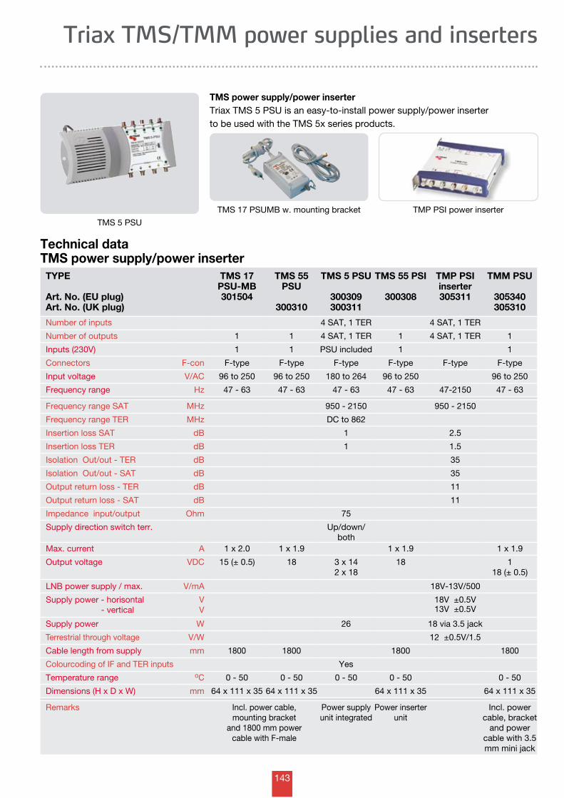
143
TYPE
Art. No. (EU plug)Art. No. (UK plug)
TMS 17 PSU-MB301504
TMS 55 PSU
300310
TMS 5 PSU
300309300311
TMS 55 PSI
300308
TMP PSIinserter305311
TMM PSU
305340305310
Number of inputs 4 SAT, 1 TER 4 SAT, 1 TER
Number of outputs 1 1 4 SAT, 1 TER 1 4 SAT, 1 TER 1
Inputs (230V) 1 1 PSU included 1 1
Connectors F-con F-type F-type F-type F-type F-type F-type
Input voltage V/AC 96 to 250 96 to 250 180 to 264 96 to 250 96 to 250
Frequency range Hz 47 - 63 47 - 63 47 - 63 47 - 63 47-2150 47 - 63
Frequency range SAT MHz 950 - 2150 950 - 2150
Frequency range TER MHz DC to 862
Insertion loss SAT dB 1 2.5
Insertion loss TER dB 1 1.5
Isolation Out/out - TER dB 35
Isolation Out/out - SAT dB 35
Output return loss - TER dB 11
Output return loss - SAT dB 11
Impedance input/output Ohm 75
Supply direction switch terr. Up/down/both
Max. current A 1 x 2.0 1 x 1.9 1 x 1.9 1 x 1.9
Output voltage VDC 15 (± 0.5) 18 3 x 142 x 18
18 118 (± 0.5)
LNB power supply / max. V/mA 18V-13V/500
Supply power - horisontal - vertical
VV
18V ±0.5V13V ±0.5V
Supply power W 26 18 via 3.5 jack
Terrestrial through voltage V/W 12 ±0.5V/1.5
Cable length from supply mm 1800 1800 1800 1800
Colourcoding of IF and TER inputs Yes
Temperature range oC 0 - 50 0 - 50 0 - 50 0 - 50 0 - 50
Dimensions (H x D x W) mm 64 x 111 x 35 64 x 111 x 35 64 x 111 x 35 64 x 111 x 35
Remarks Incl. power cable, mounting bracket
and 1800 mm power cable with F-male
Power supply unit integrated
Power inserterunit
Incl. power cable, bracket
and power cable with 3.5 mm mini jack
Technical dataTMS power supply/power inserter
Triax TMS/TMM power supplies and inserters
TMS power supply/power inserterTriax TMS 5 PSU is an easy-to-install power supply/power inserter to be used with the TMS 5x series products.
TMP PSI power inserter TMS 17 PSUMB w. mounting bracket
TMS 5 PSU
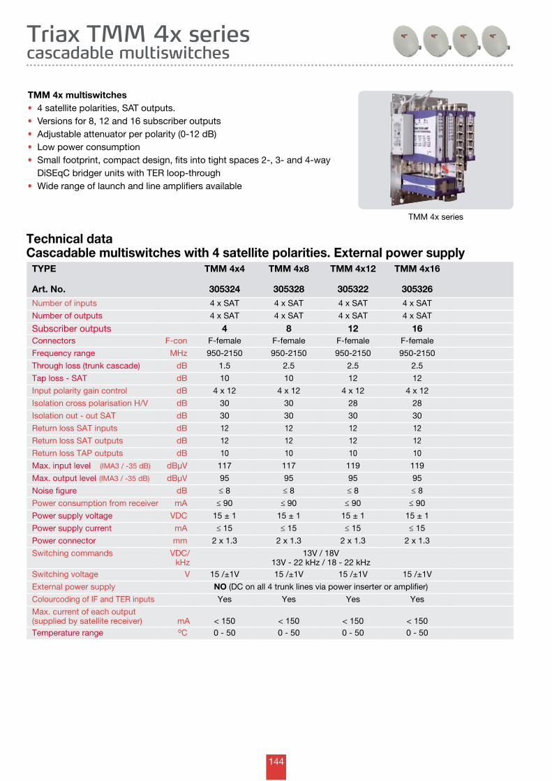
144
TYPE
Art. No.
TMM 4x4
305324
TMM 4x8
305328
TMM 4x12
305322
TMM 4x16
305326Number of inputs 4 x SAT 4 x SAT 4 x SAT 4 x SAT
Number of outputs 4 x SAT 4 x SAT 4 x SAT 4 x SAT
Subscriber outputs 4 8 12 16Connectors F-con F-female F-female F-female F-female
Frequency range MHz 950-2150 950-2150 950-2150 950-2150
Through loss (trunk cascade) dB 1.5 2.5 2.5 2.5
Tap loss - SAT dB 10 10 12 12
Input polarity gain control dB 4 x 12 4 x 12 4 x 12 4 x 12
Isolation cross polarisation H/V dB 30 30 28 28
Isolation out - out SAT dB 30 30 30 30
Return loss SAT inputs dB 12 12 12 12
Return loss SAT outputs dB 12 12 12 12
Return loss TAP outputs dB 10 10 10 10
Max. input level (IMA3 / -35 dB) dBµV 117 117 119 119
Max. output level (IMA3 / -35 dB) dBµV 95 95 95 95
Noise figure dB ≤ 8 ≤ 8 ≤ 8 ≤ 8
Power consumption from receiver mA ≤ 90 ≤ 90 ≤ 90 ≤ 90
Power supply voltage VDC 15 ± 1 15 ± 1 15 ± 1 15 ± 1
Power supply current mA ≤ 15 ≤ 15 ≤ 15 ≤ 15
Power connector mm 2 x 1.3 2 x 1.3 2 x 1.3 2 x 1.3
Switching commands VDC/kHz
13V / 18V13V - 22 kHz / 18 - 22 kHz
Switching voltage V 15 /±1V 15 /±1V 15 /±1V 15 /±1V
External power supply NO (DC on all 4 trunk lines via power inserter or amplifier)
Colourcoding of IF and TER inputs Yes Yes Yes Yes
Max. current of each output(supplied by satellite receiver) mA < 150 < 150 < 150 < 150Temperature range oC 0 - 50 0 - 50 0 - 50 0 - 50
Triax TMM 4x series cascadable multiswitches
Technical dataCascadable multiswitches with 4 satellite polarities. External power supply
TMM 4x multiswitches • 4 satellite polarities, SAT outputs.• Versions for 8, 12 and 16 subscriber outputs• Adjustable attenuator per polarity (0-12 dB)• Low power consumption • Small footprint, compact design, fits into tight spaces 2-, 3- and 4-way DiSEqC bridger units with TER loop-through• Wide range of launch and line amplifiers available
TMM 4x series
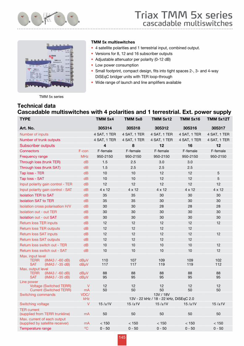
145
Triax TMM 5x series cascadable multiswitches
Technical dataCascadable multiswitches with 4 polarities and 1 terrestrial. Ext. power supply
TMM 5x series
TYPE
Art. No.
TMM 5x4
305314
TMM 5x8
305318
TMM 5x12
305312
TMM 5x16
305316
TMM 5x12T
305317Number of inputs 4 SAT, 1 TER 4 SAT, 1 TER 4 SAT, 1 TER 4 SAT, 1 TER 4 SAT, 1 TER
Number of trunk outputs 4 SAT, 1 TER 4 SAT, 1 TER 4 SAT, 1 TER 4 SAT, 1 TER 4 SAT, 1 TER
Subscriber outputs 4 8 12 16 12Connectors F-con F-female F-female F-female F-female F-female
Frequency range MHz 950-2150 950-2150 950-2150 950-2150 950-2150
Through loss (trunk TER) dB 1.5 2.5 3.0 3.0
Through loss (trunk SAT) dB 1.5 2.5 2.5 2.5
Tap loss - TER dB 10 10 12 12 5
Tap loss - SAT dB 10 10 12 12 5
Input polarity gain control - TER dB 12 12 12 12 12
Input polarity gain control - SAT dB 4 x 12 4 x 12 4 x 12 4 x 12 4 x 12
Isolation TER to SAT dB 35 35 30 30 30
Isolation SAT to TER dB 35 35 30 30 30
Isolation cross polarisation H/V dB 30 30 28 28 28
Isolation out - out TER dB 30 30 30 30 30
Isolation out - out SAT dB 30 30 30 30 30
Return loss TER inputs dB 12 12 12 12 12
Return loss TER outputs dB 12 12 12 12
Return loss SAT inputs dB 12 12 12 12 12
Return loss SAT outputs dB 12 12 12 12
Return loss switch out - TER dB 10 10 10 10 12
Return loss switch out - SAT dB 10 10 10 10 12
Max. input level TERR (IMA3 / -60 dB) SAT (IMA3 / -35 dB)
dBµVdBµV
110117
107117
109119
109119
102112
Max. output level TERR (IMA3 / -60 dB) SAT (IMA3 / -35 dB)
dBµVdBµV
8895
8895
8895
8895
8895
Line power Voltage (Switched TERR) Current (Switched TERR)
VmA
1250
1250
1250
1250
1250
Switching commands VDC/kHz
13V / 18V13V - 22 kHz / 18 - 22 kHz, DiSEqC 2.0
Switching voltage V 15 /±1V 15 /±1V 15 /±1V 15 /±1V 15 /±1V
TER current(supplied from TERR trunkline) mA 50 50 50 50 50Max. current of each output(supplied by satellite receiver) mA < 150 < 150 < 150 < 150 < 150Temperature range oC 0 - 50 0 - 50 0 - 50 0 - 50 0 - 50
TMM 5x multiswitches • 4 satellite polarities and 1 terrestrial input, combined output.• Versions for 8, 12 and 16 subscriber outputs• Adjustable attenuator per polarity (0-12 dB)• Low power consumption • Small footprint, compact design, fits into tight spaces 2-, 3- and 4-way DiSEqC bridger units with TER loop-through• Wide range of launch and line amplifiers available
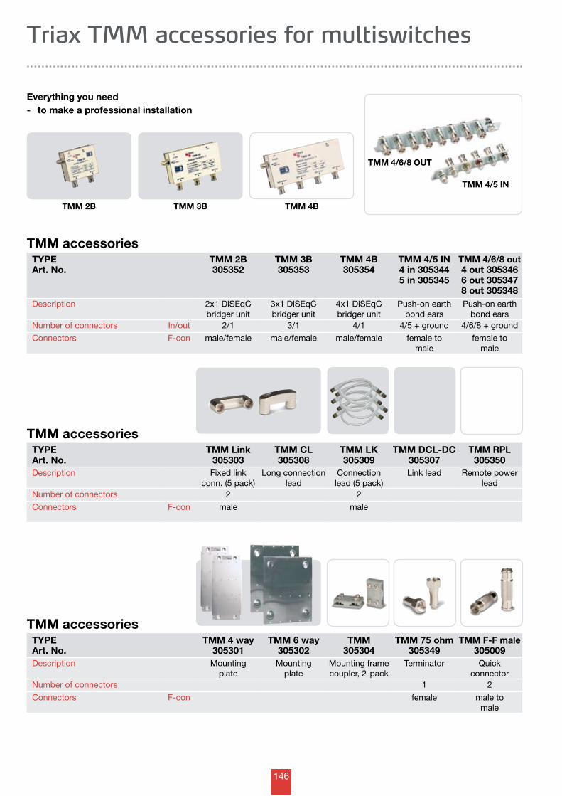
146
TMM accessoriesTYPEArt. No.
TMM 2B305352
TMM 3B305353
TMM 4B305354
TMM 4/5 IN4 in 3053445 in 305345
TMM 4/6/8 out4 out 3053466 out 3053478 out 305348
Description 2x1 DiSEqC bridger unit
3x1 DiSEqC bridger unit
4x1 DiSEqC bridger unit
Push-on earth bond ears
Push-on earth bond ears
Number of connectors In/out 2/1 3/1 4/1 4/5 + ground 4/6/8 + ground
Connectors F-con male/female male/female male/female female to male
female to male
Triax TMM accessories for multiswitches
Everything you need- to make a professional installation
TMM 4B
TMM 4/5 IN
TMM 4/6/8 OUT
TMM accessoriesTYPEArt. No.
TMM Link305303
TMM CL305308
TMM LK305309
TMM DCL-DC305307
TMM RPL305350
Description Fixed link conn. (5 pack)
Long connection lead
Connectionlead (5 pack)
Link lead Remote power lead
Number of connectors 2 2
Connectors F-con male male
TMM accessoriesTYPEArt. No.
TMM 4 way305301
TMM 6 way305302
TMM305304
TMM 75 ohm305349
TMM F-F male305009
Description Mountingplate
Mountingplate
Mounting frame coupler, 2-pack
Terminator Quick connector
Number of connectors 1 2
Connectors F-con female male to male
TMM 2B TMM 3B
147
Triax Distribution amplifiers
Antenna systems >> Outdoor amplifiers
- HNA series 148
- HTA series 149
- HDA series 150
- HEA series 151
- accessories 152-154
- HFA series 155
- accessories 156
- HEF series 157
Antenna systems >> Indoor amplifiers
- IFE series 158-159
- IFA series 160-161
- IFB series 162
- IIB series 163
- TA, Type 02, 2TV+ series 164
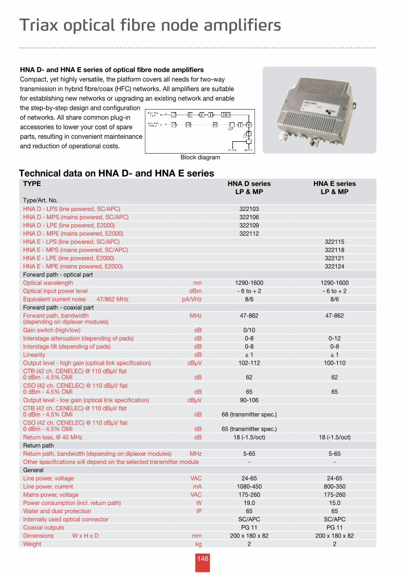
148
TYPE HNA D seriesLP & MP
HNA E seriesLP & MP
Type/Art. No.HNA D - LPS (line powered, SC/APC) 322103HNA D - MPS (mains powered, SC/APC) 322106HNA D - LPE (line powered, E2000) 322109HNA D - MPE (mains powered, E2000) 322112HNA E - LPS (line powered, SC/APC) 322115HNA E - MPS (mains powered, SC/APC) 322118HNA E - LPE (line powered, E2000) 322121HNA E - MPE (mains powered, E2000) 322124Forward path - optical partOptical wavelength nm 1290-1600 1290-1600Optical input power level dBm - 6 to + 2 - 6 to + 2Equivalent current noise 47/862 MHz pA/VHz 8/6 8/6Forward path - coaxial partForward path, bandwidth (depending on diplexer modules)
MHz 47-862 47-862
Gain switch (high/low) dB 0/10Interstage attenuation (depending of pads) dB 0-8 0-12Interstage tilt (depending of pads) dB 0-8 0-8Linearity dB ± 1 ± 1Output level - high gain (optical link specification) dBµV 102-112 100-110CTB (42 ch. CENELEC) @ 110 dBµV flat 0 dBm - 4.5% OMI dB 62 62CSO (42 ch. CENELEC) @ 110 dBµV flat 0 dBm - 4.5% OMI dB 65 65Output level - low gain (optical link specification) dBµV 90-106CTB (42 ch. CENELEC) @ 110 dBµV flat 0 dBm - 4.5% OMI dB 68 (transmitter spec.)CSO (42 ch. CENELEC) @ 110 dBµV flat 0 dBm - 4.5% OMI dB 65 (transmitter spec.)Return loss, @ 40 MHz dB 18 (-1.5/oct) 18 (-1.5/oct)Return pathReturn path, bandwidth (depending on diplexer modules) MHz 5-65 5-65Other specifications will depend on the selected transmitter module - -GeneralLine power, voltage VAC 24-65 24-65Line power, current mA 1080-450 800-350Mains power, voltage VAC 175-260 175-260Power consumption (incl. return path) W 19.0 15.0Water and dust protection IP 65 65Internally used optical connector SC/APC SC/APCCoaxial outputs PG 11 PG 11Dimensions W x H x D mm 200 x 180 x 82 200 x 180 x 82Weight kg 2 2
Triax optical fibre node amplifiers
Technical data on HNA D- and HNA E series
HNA D- and HNA E series of optical fibre node amplifiersCompact, yet highly versatile, the platform covers all needs for two-way transmission in hybrid fibre/coax (HFC) networks. All amplifiers are suitable for establishing new networks or upgrading an existing network and enable the step-by-step design and configuration of networks. All share common plug-in accessories to lower your cost of spare parts, resulting in convenient mainteinanceand reduction of operational costs.
Block diagram
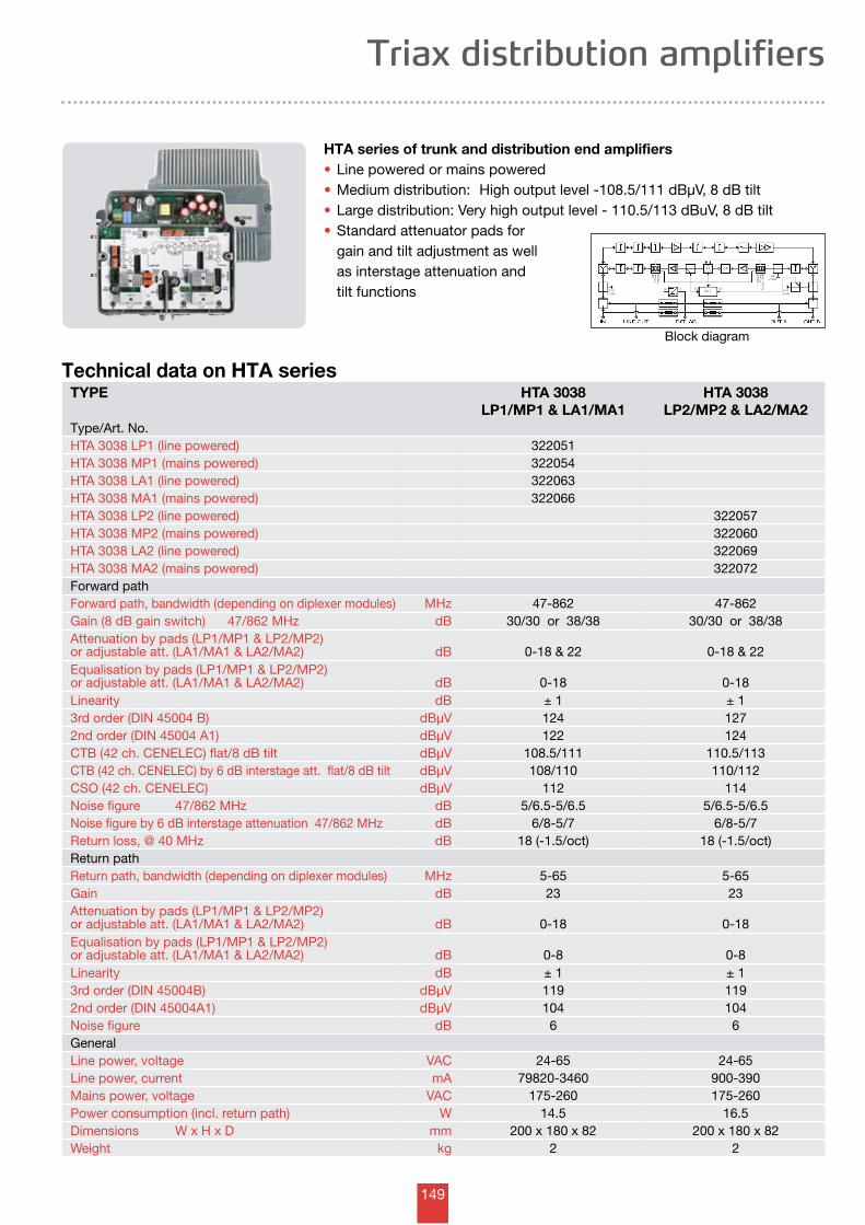
149
Triax distribution amplifiers
HTA series of trunk and distribution end amplifiers• Line powered or mains powered• Medium distribution: High output level -108.5/111 dBµV, 8 dB tilt• Large distribution: Very high output level - 110.5/113 dBuV, 8 dB tilt• Standard attenuator pads for gain and tilt adjustment as well as interstage attenuation and tilt functions
Technical data on HTA seriesTYPE HTA 3038
LP1/MP1 & LA1/MA1HTA 3038
LP2/MP2 & LA2/MA2Type/Art. No.HTA 3038 LP1 (line powered) 322051HTA 3038 MP1 (mains powered) 322054HTA 3038 LA1 (line powered) 322063HTA 3038 MA1 (mains powered) 322066HTA 3038 LP2 (line powered) 322057HTA 3038 MP2 (mains powered) 322060HTA 3038 LA2 (line powered) 322069HTA 3038 MA2 (mains powered) 322072Forward pathForward path, bandwidth (depending on diplexer modules) MHz 47-862 47-862Gain (8 dB gain switch) 47/862 MHz dB 30/30 or 38/38 30/30 or 38/38Attenuation by pads (LP1/MP1 & LP2/MP2) or adjustable att. (LA1/MA1 & LA2/MA2) dB 0-18 & 22 0-18 & 22Equalisation by pads (LP1/MP1 & LP2/MP2) or adjustable att. (LA1/MA1 & LA2/MA2) dB 0-18 0-18Linearity dB ± 1 ± 13rd order (DIN 45004 B) dBµV 124 1272nd order (DIN 45004 A1) dBµV 122 124CTB (42 ch. CENELEC) flat/8 dB tilt dBµV 108.5/111 110.5/113CTB (42 ch. CENELEC) by 6 dB interstage att. flat/8 dB tilt dBµV 108/110 110/112CSO (42 ch. CENELEC) dBµV 112 114Noise figure 47/862 MHz dB 5/6.5-5/6.5 5/6.5-5/6.5Noise figure by 6 dB interstage attenuation 47/862 MHz dB 6/8-5/7 6/8-5/7Return loss, @ 40 MHz dB 18 (-1.5/oct) 18 (-1.5/oct)Return pathReturn path, bandwidth (depending on diplexer modules) MHz 5-65 5-65Gain dB 23 23Attenuation by pads (LP1/MP1 & LP2/MP2) or adjustable att. (LA1/MA1 & LA2/MA2) dB 0-18 0-18Equalisation by pads (LP1/MP1 & LP2/MP2) or adjustable att. (LA1/MA1 & LA2/MA2) dB 0-8 0-8Linearity dB ± 1 ± 13rd order (DIN 45004B) dBµV 119 1192nd order (DIN 45004A1) dBµV 104 104Noise figure dB 6 6GeneralLine power, voltage VAC 24-65 24-65Line power, current mA 79820-3460 900-390Mains power, voltage VAC 175-260 175-260Power consumption (incl. return path) W 14.5 16.5Dimensions W x H x D mm 200 x 180 x 82 200 x 180 x 82Weight kg 2 2
Block diagram
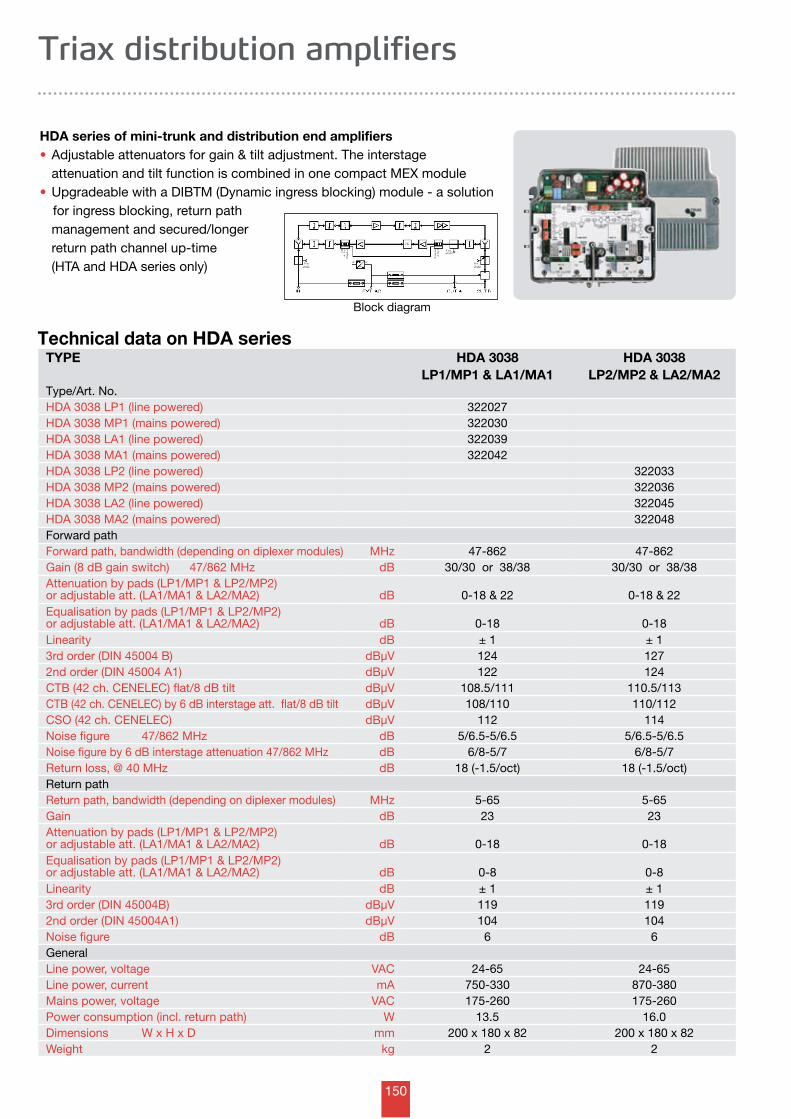
150
TYPE HDA 3038LP1/MP1 & LA1/MA1
HDA 3038LP2/MP2 & LA2/MA2
Type/Art. No.HDA 3038 LP1 (line powered) 322027HDA 3038 MP1 (mains powered) 322030HDA 3038 LA1 (line powered) 322039HDA 3038 MA1 (mains powered) 322042HDA 3038 LP2 (line powered) 322033HDA 3038 MP2 (mains powered) 322036HDA 3038 LA2 (line powered) 322045HDA 3038 MA2 (mains powered) 322048Forward pathForward path, bandwidth (depending on diplexer modules) MHz 47-862 47-862Gain (8 dB gain switch) 47/862 MHz dB 30/30 or 38/38 30/30 or 38/38Attenuation by pads (LP1/MP1 & LP2/MP2) or adjustable att. (LA1/MA1 & LA2/MA2) dB 0-18 & 22 0-18 & 22Equalisation by pads (LP1/MP1 & LP2/MP2) or adjustable att. (LA1/MA1 & LA2/MA2) dB 0-18 0-18Linearity dB ± 1 ± 13rd order (DIN 45004 B) dBµV 124 1272nd order (DIN 45004 A1) dBµV 122 124CTB (42 ch. CENELEC) flat/8 dB tilt dBµV 108.5/111 110.5/113CTB (42 ch. CENELEC) by 6 dB interstage att. flat/8 dB tilt dBµV 108/110 110/112CSO (42 ch. CENELEC) dBµV 112 114Noise figure 47/862 MHz dB 5/6.5-5/6.5 5/6.5-5/6.5Noise figure by 6 dB interstage attenuation 47/862 MHz dB 6/8-5/7 6/8-5/7Return loss, @ 40 MHz dB 18 (-1.5/oct) 18 (-1.5/oct)Return pathReturn path, bandwidth (depending on diplexer modules) MHz 5-65 5-65Gain dB 23 23Attenuation by pads (LP1/MP1 & LP2/MP2) or adjustable att. (LA1/MA1 & LA2/MA2) dB 0-18 0-18Equalisation by pads (LP1/MP1 & LP2/MP2) or adjustable att. (LA1/MA1 & LA2/MA2) dB 0-8 0-8Linearity dB ± 1 ± 13rd order (DIN 45004B) dBµV 119 1192nd order (DIN 45004A1) dBµV 104 104Noise figure dB 6 6GeneralLine power, voltage VAC 24-65 24-65Line power, current mA 750-330 870-380Mains power, voltage VAC 175-260 175-260Power consumption (incl. return path) W 13.5 16.0Dimensions W x H x D mm 200 x 180 x 82 200 x 180 x 82Weight kg 2 2
Triax distribution amplifiers
Technical data on HDA series
HDA series of mini-trunk and distribution end amplifiers• Adjustable attenuators for gain & tilt adjustment. The interstage attenuation and tilt function is combined in one compact MEX module• Upgradeable with a DIBTM (Dynamic ingress blocking) module - a solution
for ingress blocking, return path management and secured/longer return path channel up-time (HTA and HDA series only)
Block diagram
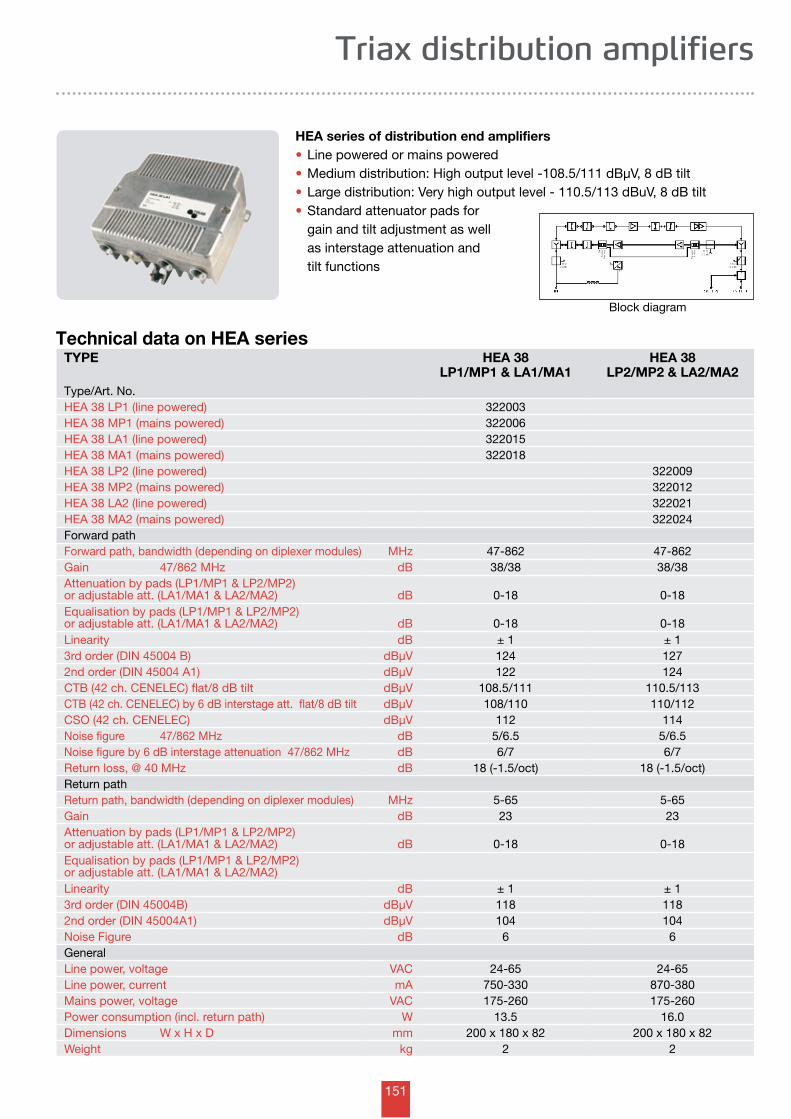
151
Triax distribution amplifiers
HEA series of distribution end amplifiers• Line powered or mains powered• Medium distribution: High output level -108.5/111 dBµV, 8 dB tilt• Large distribution: Very high output level - 110.5/113 dBuV, 8 dB tilt• Standard attenuator pads for gain and tilt adjustment as well as interstage attenuation and tilt functions
Technical data on HEA seriesTYPE HEA 38
LP1/MP1 & LA1/MA1HEA 38
LP2/MP2 & LA2/MA2Type/Art. No.HEA 38 LP1 (line powered) 322003HEA 38 MP1 (mains powered) 322006HEA 38 LA1 (line powered) 322015HEA 38 MA1 (mains powered) 322018HEA 38 LP2 (line powered) 322009HEA 38 MP2 (mains powered) 322012HEA 38 LA2 (line powered) 322021HEA 38 MA2 (mains powered) 322024Forward pathForward path, bandwidth (depending on diplexer modules) MHz 47-862 47-862Gain 47/862 MHz dB 38/38 38/38Attenuation by pads (LP1/MP1 & LP2/MP2) or adjustable att. (LA1/MA1 & LA2/MA2) dB 0-18 0-18Equalisation by pads (LP1/MP1 & LP2/MP2) or adjustable att. (LA1/MA1 & LA2/MA2) dB 0-18 0-18Linearity dB ± 1 ± 13rd order (DIN 45004 B) dBµV 124 1272nd order (DIN 45004 A1) dBµV 122 124CTB (42 ch. CENELEC) flat/8 dB tilt dBµV 108.5/111 110.5/113CTB (42 ch. CENELEC) by 6 dB interstage att. flat/8 dB tilt dBµV 108/110 110/112CSO (42 ch. CENELEC) dBµV 112 114Noise figure 47/862 MHz dB 5/6.5 5/6.5Noise figure by 6 dB interstage attenuation 47/862 MHz dB 6/7 6/7Return loss, @ 40 MHz dB 18 (-1.5/oct) 18 (-1.5/oct)Return pathReturn path, bandwidth (depending on diplexer modules) MHz 5-65 5-65Gain dB 23 23Attenuation by pads (LP1/MP1 & LP2/MP2) or adjustable att. (LA1/MA1 & LA2/MA2) dB 0-18 0-18Equalisation by pads (LP1/MP1 & LP2/MP2) or adjustable att. (LA1/MA1 & LA2/MA2)Linearity dB ± 1 ± 13rd order (DIN 45004B) dBµV 118 1182nd order (DIN 45004A1) dBµV 104 104Noise Figure dB 6 6GeneralLine power, voltage VAC 24-65 24-65Line power, current mA 750-330 870-380Mains power, voltage VAC 175-260 175-260Power consumption (incl. return path) W 13.5 16.0Dimensions W x H x D mm 200 x 180 x 82 200 x 180 x 82Weight kg 2 2
Block diagram
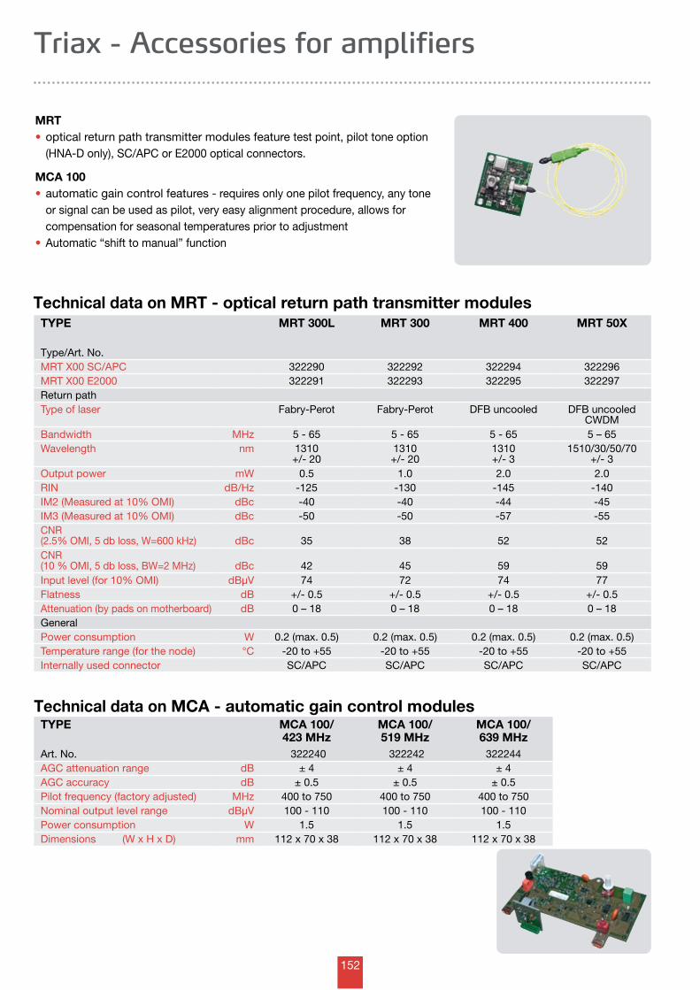
152
TYPE MRT 300L MRT 300 MRT 400 MRT 50X
Type/Art. No.MRT X00 SC/APC 322290 322292 322294 322296MRT X00 E2000 322291 322293 322295 322297Return pathType of laser Fabry-Perot Fabry-Perot DFB uncooled DFB uncooled
CWDMBandwidth MHz 5 - 65 5 - 65 5 - 65 5 – 65 Wavelength nm 1310
+/- 201310 +/- 20
1310 +/- 3
1510/30/50/70+/- 3
Output power mW 0.5 1.0 2.0 2.0RIN dB/Hz -125 -130 -145 -140IM2 (Measured at 10% OMI) dBc -40 -40 -44 -45IM3 (Measured at 10% OMI) dBc -50 -50 -57 -55CNR (2.5% OMI, 5 db loss, W=600 kHz) dBc 35 38 52 52CNR (10 % OMI, 5 db loss, BW=2 MHz) dBc 42 45 59 59Input level (for 10% OMI) dBµV 74 72 74 77Flatness dB +/- 0.5 +/- 0.5 +/- 0.5 +/- 0.5Attenuation (by pads on motherboard) dB 0 – 18 0 – 18 0 – 18 0 – 18GeneralPower consumption W 0.2 (max. 0.5) 0.2 (max. 0.5) 0.2 (max. 0.5) 0.2 (max. 0.5)Temperature range (for the node) °C -20 to +55 -20 to +55 -20 to +55 -20 to +55Internally used connector SC/APC SC/APC SC/APC SC/APC
Technical data on MCA - automatic gain control modulesTYPE MCA 100/
423 MHzMCA 100/519 MHz
MCA 100/639 MHz
Art. No. 322240 322242 322244AGC attenuation range dB ± 4 ± 4 ± 4AGC accuracy dB ± 0.5 ± 0.5 ± 0.5Pilot frequency (factory adjusted) MHz 400 to 750 400 to 750 400 to 750Nominal output level range dBµV 100 - 110 100 - 110 100 - 110Power consumption W 1.5 1.5 1.5Dimensions (W x H x D) mm 112 x 70 x 38 112 x 70 x 38 112 x 70 x 38
Triax - Accessories for amplifiers
Technical data on MRT - optical return path transmitter modules
MRT• optical return path transmitter modules feature test point, pilot tone option (HNA-D only), SC/APC or E2000 optical connectors.
MCA 100• automatic gain control features - requires only one pilot frequency, any tone or signal can be used as pilot, very easy alignment procedure, allows for compensation for seasonal temperatures prior to adjustment• Automatic “shift to manual” function
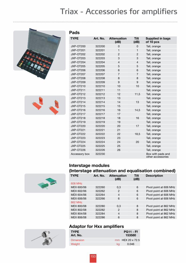
153
TYPE Art. No. Attenuation (dB)
Tilt (dB)
Supplied in bags of 10 pcs
JXP-OT200 322200 0 0 Tall, orangeJXP-OT201 322201 1 1 Tall, orangeJXP-OT202 322202 2 2 Tall, orangeJXP-OT203 322203 3 3 Tall, orangeJXP-OT204 322204 4 4 Tall, orangeJXP-OT205 322205 5 5 Tall, orangeJXP-OT206 322206 6 6 Tall, orangeJXP-OT207 322207 7 7 Tall, orangeJXP-OT208 322208 8 8 Tall, orangeJXP-OT209 322209 9 9 Tall, orangeJXP-OT210 322210 10 10 Tall, orangeJXP-OT211 322211 11 Tall, orangeJXP-OT212 322212 12 11,5 Tall, orangeJXP-OT213 322213 13 Tall, orangeJXP-OT214 322214 14 13 Tall, orangeJXP-OT215 322215 15 Tall, orangeJXP-OT216 322216 16 14,5 Tall, orangeJXP-OT217 322217 17 Tall, orangeJXP-OT218 322218 18 16 Tall, orangeJXP-OT219 322219 19 Tall, orangeJXP-OT220 322220 20 17 Tall, orangeJXP-OT221 322221 21 Tall, orangeJXP-OT222 322222 22 18,5 Tall, orangeJXP-OT223 322223 23 Tall, orangeJXP-OT224 322224 24 20 Tall, orangeJXP-OT225 322225 25 Tall, orangeJXP-OT226 322226 26 Tall, orangeAccessory box 322230 Box with pads and
other accessories
Pads
TYPE Art. No. Attenuation (dB)
Tilt (dB)
Description
606 MHzMEX 600/06 322260 0,3 6 Pivot point at 606 MHzMEX 602/06 322262 2 6 Pivot point at 606 MHzMEX 604/06 322264 4 6 Pivot point at 606 MHzMEX 606/06 322266 6 6 Pivot point at 606 MHz862 MHzMEX 800/08 322280 0,3 8 Pivot point at 862 MHzMEX 802/08 322282 2 8 Pivot point at 862 MHzMEX 804/08 322284 4 8 Pivot point at 862 MHzMEX 806/08 322286 6 8 Pivot point at 862 MHz
Interstage modules (Interstage attenuation and equalisation combined)
Triax - Accessories for amplifiers
Adaptor for Hxx amplifiersTYPEArt. No.
PG11 - Ff153580
Dimension mm HEX 20 x 72.5Weight kg 0.046
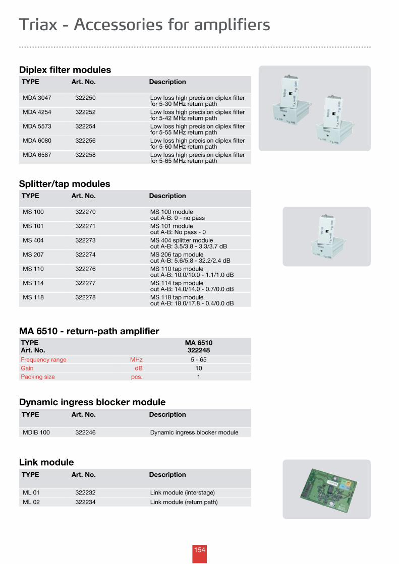
154
MA 6510 - return-path amplifierTYPEArt. No.
MA 6510322248
Frequency range MHz 5 - 65Gain dB 10Packing size pcs. 1
TYPE Art. No. Description
MDA 3047 322250 Low loss high precision diplex filter for 5-30 MHz return path
MDA 4254 322252 Low loss high precision diplex filter for 5-42 MHz return path
MDA 5573 322254 Low loss high precision diplex filter for 5-55 MHz return path
MDA 6080 322256 Low loss high precision diplex filter for 5-60 MHz return path
MDA 6587 322258 Low loss high precision diplex filter for 5-65 MHz return path
Diplex filter modules
Dynamic ingress blocker module
Triax - Accessories for amplifiers
TYPE Art. No. Description
MS 100 322270 MS 100 moduleout A-B: 0 - no pass
MS 101 322271 MS 101 moduleout A-B: No pass - 0
MS 404 322273 MS 404 splitter moduleout A-B: 3.5/3.8 - 3.3/3.7 dB
MS 207 322274 MS 206 tap moduleout A-B: 5.6/5.8 - 32.2/2.4 dB
MS 110 322276 MS 110 tap moduleout A-B: 10.0/10.0 - 1.1/1.0 dB
MS 114 322277 MS 114 tap moduleout A-B: 14.0/14.0 - 0.7/0.0 dB
MS 118 322278 MS 118 tap moduleout A-B: 18.0/17.8 - 0.4/0.0 dB
Splitter/tap modules
TYPE Art. No. Description
MDIB 100 322246 Dynamic ingress blocker module
Link moduleTYPE Art. No. Description
ML 01 322232 Link module (interstage)
ML 02 322234 Link module (return path)
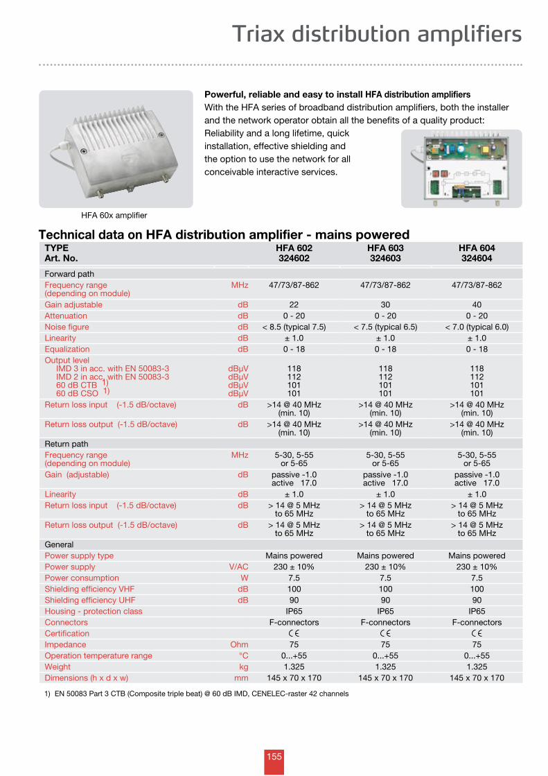
155
TYPEArt. No.
HFA 602 324602
HFA 603324603
HFA 604 324604
Forward pathFrequency range(depending on module)
MHz 47/73/87-862 47/73/87-862 47/73/87-862
Gain adjustable dB 22 30 40Attenuation dB 0 - 20 0 - 20 0 - 20Noise figure dB < 8.5 (typical 7.5) < 7.5 (typical 6.5) < 7.0 (typical 6.0)Linearity dB ± 1.0 ± 1.0 ± 1.0 Equalization dB 0 - 18 0 - 18 0 - 18Output level IMD 3 in acc. with EN 50083-3 IMD 2 in acc. with EN 50083-3 60 dB CTB 1) 60 dB CSO 1)
dBµVdBµVdBµVdBµV
118112101101
118112101101
118112101101
Return loss input (-1.5 dB/octave) dB >14 @ 40 MHz(min. 10)
>14 @ 40 MHz(min. 10)
>14 @ 40 MHz(min. 10)
Return loss output (-1.5 dB/octave) dB >14 @ 40 MHz(min. 10)
>14 @ 40 MHz(min. 10)
>14 @ 40 MHz(min. 10)
Return pathFrequency range(depending on module)
MHz 5-30, 5-55 or 5-65
5-30, 5-55 or 5-65
5-30, 5-55 or 5-65
Gain (adjustable) dB passive -1.0active 17.0
passive -1.0active 17.0
passive -1.0active 17.0
Linearity dB ± 1.0 ± 1.0 ± 1.0Return loss input (-1.5 dB/octave) dB > 14 @ 5 MHz
to 65 MHz> 14 @ 5 MHz
to 65 MHz> 14 @ 5 MHz
to 65 MHzReturn loss output (-1.5 dB/octave) dB > 14 @ 5 MHz
to 65 MHz> 14 @ 5 MHz
to 65 MHz> 14 @ 5 MHz
to 65 MHzGeneralPower supply type Mains powered Mains powered Mains poweredPower supply V/AC 230 ± 10% 230 ± 10% 230 ± 10%Power consumption W 7.5 7.5 7.5Shielding efficiency VHF dB 100 100 100Shielding efficiency UHF dB 90 90 90Housing - protection class IP65 IP65 IP65Connectors F-connectors F-connectors F-connectorsCertificationImpedance Ohm 75 75 75Operation temperature range °C 0...+55 0...+55 0...+55Weight kg 1.325 1.325 1.325Dimensions (h x d x w) mm 145 x 70 x 170 145 x 70 x 170 145 x 70 x 170
1) EN 50083 Part 3 CTB (Composite triple beat) @ 60 dB IMD, CENELEC-raster 42 channels
Triax distribution amplifiers
Powerful, reliable and easy to install HFA distribution amplifiersWith the HFA series of broadband distribution amplifiers, both the installer and the network operator obtain all the benefits of a quality product: Reliability and a long lifetime, quick installation, effective shielding and the option to use the network for all conceivable interactive services.
Technical data on HFA distribution amplifier - mains powered
HFA 60x amplifier
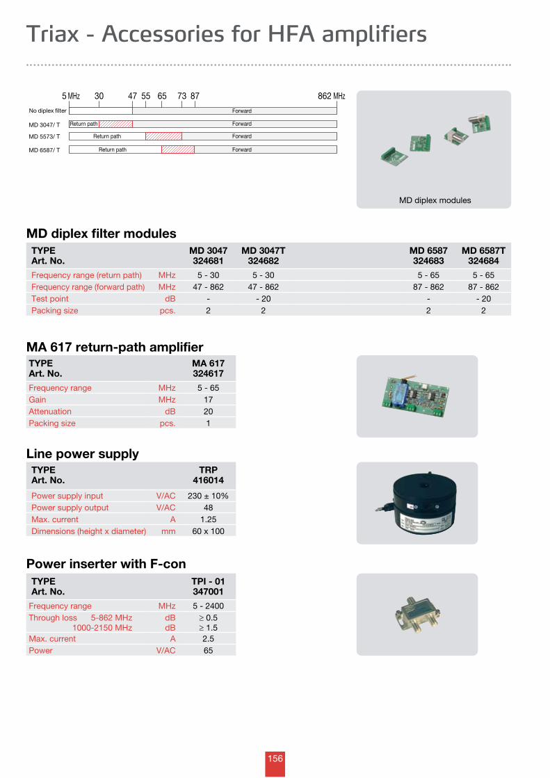
156
No diplex filter
MD 3047/ T
5 MHz 30 47 87 862 MHz
Forward
MD 5573/ T
MD 6587/ T
6555 73
ForwardReturn path
Return path Forward
ForwardReturn path
TYPEArt. No.
MD 3047324681
MD 3047T324682
MD 6587324683
MD 6587T324684
Frequency range (return path) MHz 5 - 30 5 - 30 5 - 65 5 - 65Frequency range (forward path) MHz 47 - 862 47 - 862 87 - 862 87 - 862Test point dB - - 20 - - 20Packing size pcs. 2 2 2 2
MA 617 return-path amplifier
Line power supplyTYPEArt. No.
TRP416014
Power supply input V/AC 230 ± 10%Power supply output V/AC 48Max. current A 1.25Dimensions (height x diameter) mm 60 x 100
Power inserter with F-conTYPEArt. No.
TPI - 01347001
Frequency range MHz 5 - 2400Through loss 5-862 MHz 1000-2150 MHz
dBdB
≥ 0.5≥ 1.5
Max. current A 2.5Power V/AC 65
Triax - Accessories for HFA amplifiers
MD diplex filter modules
TYPEArt. No.
MA 617324617
Frequency range MHz 5 - 65Gain MHz 17Attenuation dB 20Packing size pcs. 1
MD diplex modules
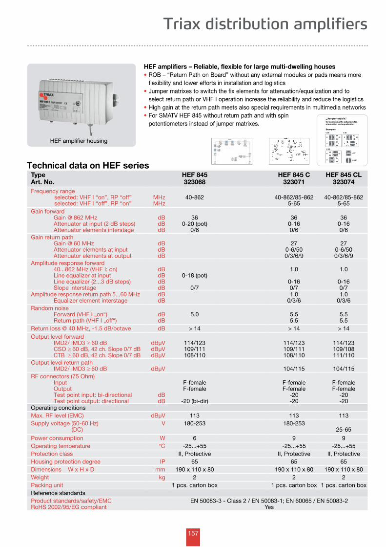
157
Examples:
14 dB
0 dB 4 dB
6
„ein“
„0 dB“
12
2 4
6 12
2 4
6 12
2 4
„Jumper-matrix“
for combining the actuators forattenuation and equalization
0/3/5 dB
L
L
Triax distribution amplifiers
TypeArt. No.
HEF 845323068
HEF 845 C323071
HEF 845 CL323074
Frequency range selected: VHF I “on”, RP “off” selected: VHF I “off”, RP “on”
MHzMHz
40-862 40-862/85-8625-65
40-862/85-8625-65
Gain forward Gain @ 862 MHz Attenuator at input (2 dB steps) Attenuator elements interstage
dBdBdB
360-20 (pot)
0/6
360-160/6
360-160/6
Gain return path Gain @ 60 MHz Attenuator elements at input Attenuator elements at output
dBdBdB
270-6/500/3/6/9
270-6/500/3/6/9
Amplitude response forward 40...862 MHz (VHF I: on) Line equalizer at input Line equalizer (2...3 dB steps) Slope interstage
dBdBdBdB
0-18 (pot)
0/7
1.0
0-160/7
1.0
0-160/7
Amplitude response return path 5...60 MHz Equalizer element interstage
dBdB
1.00/3/6
1.00/3/6
Random noise Forward (VHF I „on“) Return path (VHF I „off“)
dBdB
5.0 5.55.5
5.55.5
Return loss @ 40 MHz, -1.5 dB/octave dB > 14 > 14 > 14Output level forward IMD2/ IMD3 ≥ 60 dB CSO ≥ 60 dB, 42 ch. Slope 0/7 dB CTB ≥ 60 dB, 42 ch. Slope 0/7 dB
dBµVdBµVdBµV
114/123109/111108/110
114/123109/111108/110
114/123109/108111/110
Output level return path IMD2/ IMD3 ≥ 60 dB dBµV 104/115 104/115RF connectors (75 Ohm) Input Output Test point input: bi-directional Test point output: directional
dBdB
F-femaleF-female
-20 (bi-dir)
F-femaleF-female
-20 -20
F-femaleF-female
-20 -20
Operating conditionsMax. RF level (EMC) dBµV 113 113 113Supply voltage (50-60 Hz) (DC)
V 180-253 180-25325-65
Power consumption W 6 9 9Operating temperature °C -25...+55 -25...+55 -25...+55Protection class II, Protective II, Protective II, ProtectiveHousing protection degree IP 65 65 65Dimensions W x H x D mm 190 x 110 x 80 190 x 110 x 80 190 x 110 x 80Weight kg 2 2 2Packing unit 1 pcs. carton box 1 pcs. carton box 1 pcs. carton boxReference standardsProduct standards/safety/EMCRoHS 2002/95/EG compliant
EN 50083-3 - Class 2 / EN 50083-1; EN 60065 / EN 50083-2Yes
Technical data on HEF series
HEF amplifiers – Reliable, flexible for large multi-dwelling houses• ROB – “Return Path on Board” without any external modules or pads means more flexibility and lower efforts in installation and logistics• Jumper matrixes to switch the fix elements for attenuation/equalization and to select return path or VHF I operation increase the reliability and reduce the logistics• High gain at the return path meets also special requirements in multimedia networks• For SMATV HEF 845 without return path and with spin potentiometers instead of jumper matrixes.
HEF amplifier housing
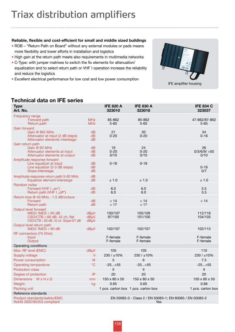
158
Triax distribution amplifiers
Reliable, flexible and cost-efficient for small and middle sized buildings• ROB – “Return Path on Board” without any external modules or pads means more flexibility and lower efforts in installation and logistics• High gain at the return path meets also requirements in multimedia networks• C-Type: with jumper matrixes to switch the fix elements for attenuation/ equalization and to select return path or VHF I operation increase the reliability and reduce the logistics• Excellent electrical performance for low cost and low power consumption
Technical data on IFE series
IFE amplifier housing
TypeArt. No.
IFE 820 A323010
IFE 830 A323016
IFE 834 C323037
Frequency range Forward path Return path
MHzMHz
85-8625-65
85-8625-65
47-862/87-8625-65
Gain forward Gain @ 862 MHz Attenuator at input (2 dB steps) Attenuator elements interstage
dBdBdB
210-20
300-20
340-16
Gain return path Gain @ 60 MHz Attenuator elements at input Attenuator elements at output
dBdBdB
190-200/10
240-200/10
260/3/6/9/ >50
0/10Amplitude response forward Line equalizer at input Line equalizer (2-3 dB steps) Slope interstage
dBdBdB
0-18 0-180-160/7
Amplitude response return path 5-60 MHz Equalizer element interstage
dBdB ± 1.0 ± 1.0 ± 1.0
Random noise Forward (VHF I „on“) Return path (VHF I „off“)
dBdB
6.06.0
6.06.0
5.55.5
Return loss @ 40 MHz, -1.5 dB/octave Forward Return path
dBdB
> 14> 17
> 14> 17
> 14
Output level forward IMD2/ IMD3 ≥ 60 dB CSO/CTB ≥ 60 dB. 42 ch, flat CSO/CTB ≥ 60 dB, 42 ch. Slope 0/7 dB
dBµVdBµVdBµV
100/10797/100
105/109101/100
112/118104/103
Output level return path IMD2/ IMD3 ≥ 60 dB dBµV 102/107 102/107 102/113RF connectors (75 Ohm) Input Output
F-femaleF-female
F-femaleF-female
F-femaleF-female
Operating conditionsMax. RF level (EMC) dBµV 105 105 110Supply voltage V 230 / ±10% 230 / ±10% 230 / ±10%Power consumption W 5 6 7.5Operating temperature °C -25...+55 -25...+55 -25...+55Protection class II II IIDegree of protection IP 20 20 20Dimensions W x H x D mm 150 x 80 x 50 150 x 80 x 50 150 x 80 x 50Weight kg 0.65 0.65 0.68Packing unit 1 pcs. carton box 1 pcs. carton box 1 pcs. carton boxReference standardsProduct standards/safety/EMCRoHS 2002/95/EG compliant
EN 50083-3 - Class 2 / EN 50083-1; EN 60065 / EN 50083-2Yes
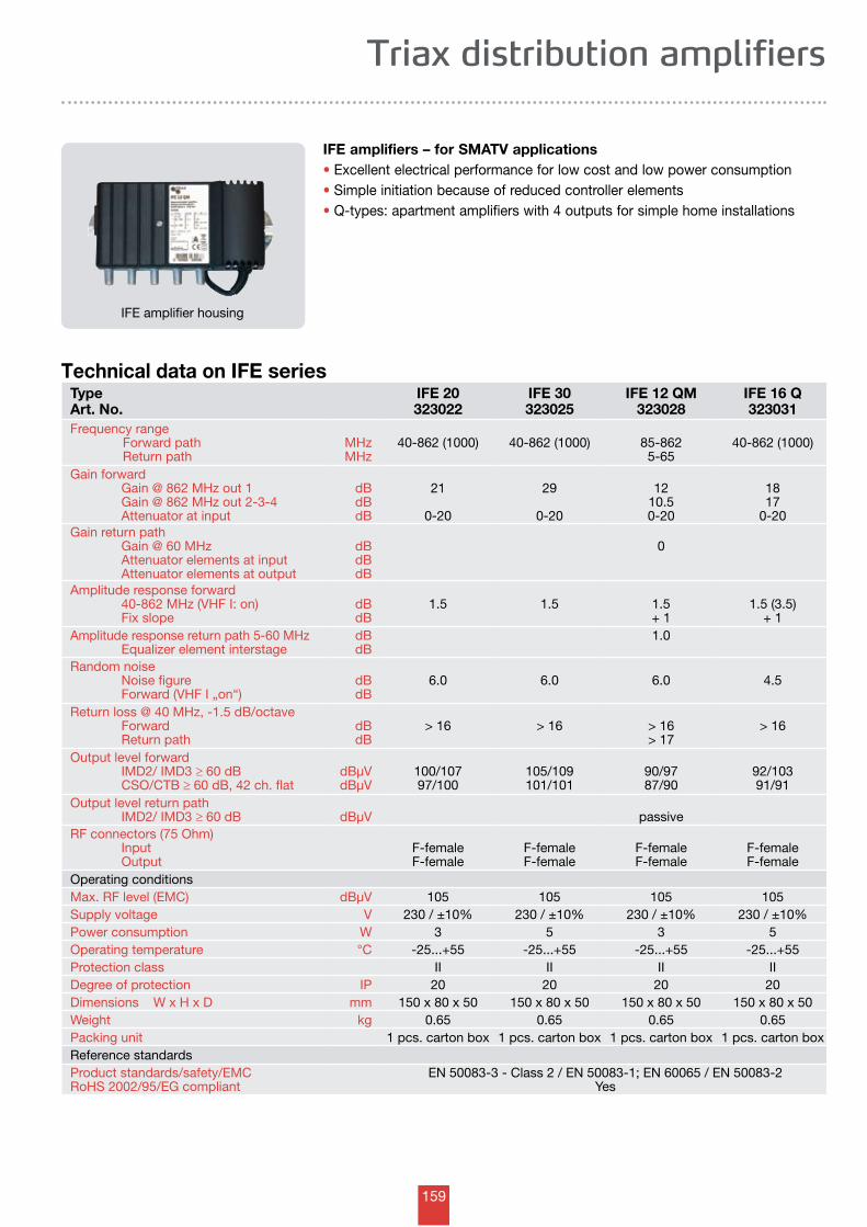
159
Triax distribution amplifiers
IFE amplifier housing
IFE amplifiers – for SMATV applications• Excellent electrical performance for low cost and low power consumption• Simple initiation because of reduced controller elements• Q-types: apartment amplifiers with 4 outputs for simple home installations
Technical data on IFE seriesTypeArt. No.
IFE 20323022
IFE 30 323025
IFE 12 QM 323028
IFE 16 Q 323031
Frequency range Forward path Return path
MHzMHz
40-862 (1000) 40-862 (1000) 85-8625-65
40-862 (1000)
Gain forward Gain @ 862 MHz out 1 Gain @ 862 MHz out 2-3-4 Attenuator at input
dBdBdB
21
0-20
29
0-20
1210.50-20
1817
0-20Gain return path Gain @ 60 MHz Attenuator elements at input Attenuator elements at output
dBdBdB
0
Amplitude response forward 40-862 MHz (VHF I: on) Fix slope
dBdB
1.5 1.5 1.5+ 1
1.5 (3.5)+ 1
Amplitude response return path 5-60 MHz Equalizer element interstage
dBdB
1.0
Random noise Noise figure Forward (VHF I „on“)
dBdB
6.0 6.0 6.0 4.5
Return loss @ 40 MHz, -1.5 dB/octave Forward Return path
dBdB
> 16 > 16 > 16> 17
> 16
Output level forward IMD2/ IMD3 ≥ 60 dB CSO/CTB ≥ 60 dB, 42 ch. flat
dBµVdBµV
100/10797/100
105/109101/101
90/9787/90
92/10391/91
Output level return path IMD2/ IMD3 ≥ 60 dB dBµV passiveRF connectors (75 Ohm) Input Output
F-femaleF-female
F-femaleF-female
F-femaleF-female
F-femaleF-female
Operating conditionsMax. RF level (EMC) dBµV 105 105 105 105Supply voltage V 230 / ±10% 230 / ±10% 230 / ±10% 230 / ±10%Power consumption W 3 5 3 5Operating temperature °C -25...+55 -25...+55 -25...+55 -25...+55Protection class II II II IIDegree of protection IP 20 20 20 20Dimensions W x H x D mm 150 x 80 x 50 150 x 80 x 50 150 x 80 x 50 150 x 80 x 50Weight kg 0.65 0.65 0.65 0.65Packing unit 1 pcs. carton box 1 pcs. carton box 1 pcs. carton box 1 pcs. carton boxReference standardsProduct standards/safety/EMCRoHS 2002/95/EG compliant
EN 50083-3 - Class 2 / EN 50083-1; EN 60065 / EN 50083-2Yes
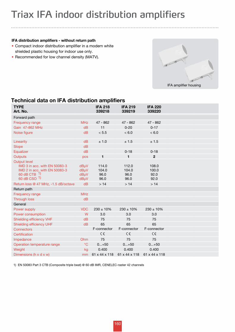
160
Triax IFA indoor distribution amplifiers
IFA distribution amplifiers - without return path • Compact indoor distribution amplifier in a modern white shielded plastic housing for indoor use only.• Recommended for low channel density (MATV).
Technical data on IFA distribution amplifiers
IFA amplifier housing
TYPEArt. No.
IFA 218339218
IFA 219339219
IFA 220339220
Forward pathFrequency range MHz 47 - 862 47 - 862 47 - 862Gain 47-862 MHz dB 11 0-20 0-17Noise figure dB < 5.5 < 6.0 < 6.0
Linearity dB ± 1.0 ± 1.5 ± 1.5Slope dBEqualizer dB 0-18 0-18Outputs pcs 1 1 2Output level IMD 3 in acc. with EN 50083-3 IMD 2 in acc. with EN 50083-3 60 dB CTB 1)
60 dB CSO 1)
dBµVdBµVdBµVdBµV
114.0104.096.096.0
112.0104.096.096.0
108.0100.092.092.0
Return loss @ 47 MHz, -1.5 dB/octave dB > 14 > 14 > 14Return pathFrequency range MHzThrough loss dBGeneralPower supply VDC 230 ± 10% 230 ± 10% 230 ± 10%Power consumption W 3.0 3.0 3.0Shielding efficiency VHF dB 75 75 75Shielding efficiency UHF dB 65 65 65Connectors F-connector F-connector F-connector
CertificationImpedance Ohm 75 75 75Operation temperature range °C 0...+50 0...+50 0...+50Weight kg 0.400 0.400 0.400Dimensions (h x d x w) mm 61 x 44 x 118 61 x 44 x 118 61 x 44 x 118
1) EN 50083 Part 3 CTB (Composite triple beat) @ 60 dB IMR, CENELEC-raster 42 channels
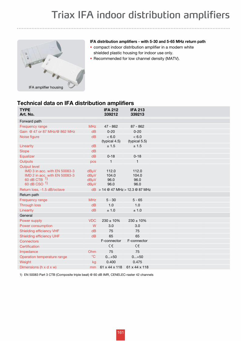
161
Triax IFA indoor distribution amplifiers
IFA amplifier housing
IFA distribution amplifiers - with 5-30 and 5-65 MHz return path • compact indoor distribution amplifier in a modern white shielded plastic housing for indoor use only.• Recommended for low channel density (MATV).
Technical data on IFA distribution amplifiersTYPEArt. No.
IFA 212339212
IFA 213339213
Forward pathFrequency range MHz 47 - 862 87 - 862Gain @ 47 or 87 MHz/@ 862 MHz dB 0-20 0-20Noise figure dB < 6.0
(typical 4.5)< 6.0
(typical 5.5)Linearity dB ± 1.5 ± 1.5Slope dBEqualizer dB 0-18 0-18Outputs pcs 1 1Output level IMD 3 in acc. with EN 50083-3 IMD 2 in acc. with EN 50083-3 60 dB CTB 1)
60 dB CSO 1)
dBµVdBµVdBµVdBµV
112.0104.096.096.0
112.0104.096.096.0
Return loss, -1.5 dB/octave dB > 14 @ 47 MHz > 12.3 @ 87 MHzReturn pathFrequency range MHz 5 - 30 5 - 65Through loss dB 1.0 1.0Linearity dB ± 1.0 ± 1.0GeneralPower supply VDC 230 ± 10% 230 ± 10%Power consumption W 3.0 3.0Shielding efficiency VHF dB 75 75Shielding efficiency UHF dB 65 65Connectors F-connector F-connector
CertificationImpedance Ohm 75 75Operation temperature range °C 0...+50 0...+50Weight kg 0.400 0.475Dimensions (h x d x w) mm 61 x 44 x 118 61 x 44 x 118
1) EN 50083 Part 3 CTB (Composite triple beat) @ 60 dB IMR, CENELEC-raster 42 channels
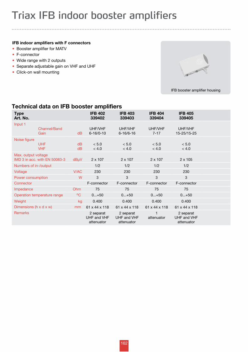
162
Triax IFB indoor booster amplifiers
IFB indoor amplifiers with F connectors • Booster amplifier for MATV• F-connector• Wide range with 2 outputs• Separate adjustable gain on VHF and UHF• Click-on wall mounting
Technical data on IFB booster amplifiers
IFB booster amplifier housing
Type Art. No.
IFB 402339402
IFB 403339403
IFB 404339404
IFB 405339405
Input 1 Channel/Band Gain dB
UHF/VHF6-16/0-10
UHF/VHF6-16/6-16
UHF/VHF7-17
UHF/VHF15-25/15-25
Noise figure UHF VHF
dBdB
< 5.0< 4.0
< 5.0< 4.0
< 5.0< 4.0
< 5.0< 4.0
Max. output voltageIMD 3 in acc. with EN 50083-3 dBµV 2 x 10⁷ 2 x 10⁷ 2 x 10⁷ 2 x 10⁵
Numbers of in-/output 1/2 1/2 1/2 1/2
Voltage V/AC 230 230 230 230
Power consumption W 3 3 3 3
Connector F-connector F-connector F-connector F-connector
Impedance Ohm 75 75 75 75
Operation temperature range oC 0...+50 0...+50 0...+50 0...+50
Weight kg 0.400 0.400 0.400 0.400
Dimensions (h x d x w) mm 61 x 44 x 118 61 x 44 x 118 61 x 44 x 118 61 x 44 x 118
Remarks 2 separat UHF and VHF
attenuator
2 separat UHF and VHF
attenuator
1attenuator
2 separat UHF and VHF
attenuator
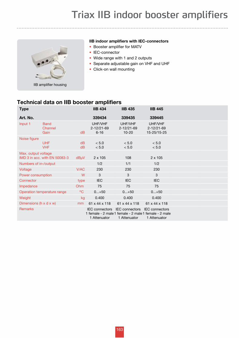
163
Triax IIB indoor booster amplifiers
IIB indoor amplifiers with IEC-connectors • Booster amplifier for MATV• IEC-connector• Wide range with 1 and 2 outputs• Separate adjustable gain on VHF and UHF• Click-on wall mounting
Technical data on IIB booster amplifiersType
Art. No.
IIB 434
339434
IIB 435
339435
IIB 445
339445Input 1 Band Channel Gain dB
UHF/VHF2-12/21-69
6-16
UHF/VHF2-12/21-69
10-20
UHF/VHF2-12/21-69
15-25/15-25
Noise figure UHF VHF
dBdB
< 5.0< 5.0
< 5.0< 5.0
< 5.0< 5.0
Max. output voltageIMD 3 in acc. with EN 50083-3 dBµV 2 x 10⁵ 108 2 x 10⁵
Numbers of in-/output 1/2 1/1 1/2
Voltage V/AC 230 230 230
Power consumption W 3 3 3
Connector type IEC IEC IEC
Impedance Ohm 75 75 75
Operation temperature range oC 0...+50 0...+50 0...+50
Weight kg 0.400 0.400 0.400
Dimensions (h x d x w) mm 61 x 44 x 118 61 x 44 x 118 61 x 44 x 118
Remarks IEC connectors1 female - 2 male
1 Attenuator
IEC connectors1 female - 2 male
1 Attenuator
IEC connectors1 female - 2 male
1 Attenuator
IIB amplifier housing
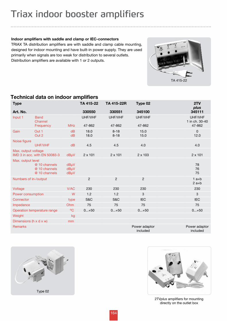
164
Triax indoor booster amplifiers
Indoor amplifiers with saddle and clamp or IEC-connectors TRIAX TA distribution amplifiers are with saddle and clamp cable mounting, designed for indoor mounting and have built-in power supply. They are used primarily when signals are too weak for distribution to several outlets. Distribution amplifiers are available with 1 or 2 outputs.
Technical data on indoor amplifiersType
Art. No.
TA 415-22
330550
TA 415-22R
330551
Type 02
345100
2TVplus
345111Input 1 Band Channel Frequency MHz
UHF/VHF
47-862
UHF/VHF
47-862
UHF/VHF
47-862
UHF/VHF1 in ch. 30-40
47-862
Gain Out 1 Out 2
dBdB
18.018.0
8-188-18
15.015.0
012.0
Noise figure UHF/VHF dB 4.5 4.5 4.0 4.0
Max. output voltageIMD 3 in acc. with EN 50083-3 dBµV 2 x 101 2 x 101 2 x 10³ 2 x 101
Max. output level @ 10 channels @ 10 channels @ 10 channels
dBµVdBµVdBµV
787675
Numbers of in-/output 2 2 2 1 a+b2 a+b
Voltage V/AC 230 230 230 230
Power consumption W 1.2 1.2 3 3
Connector type S&C S&C IEC IEC
Impedance Ohm 75 75 75 75
Operation temperature range oC 0...+50 0...+50 0...+50 0...+50
Weight kg
Dimensions (h x d x w) mm
Remarks Power adaptorincluded
Power adaptorincluded
Type 02
2TVplus amplifiers for mounting directly on the outlet box
TA 415-22
165
Triax passive components
Antenna systems >> Splitters, taps and cables
- A-TECH 5-1000 MHz 166-171
- H-TECH 5-1000 MHz 172-178
- S-TECH 5-2400 MHz 179-183
TDP delivery point 184
TLS range of outdoor splitters 185
TLT range of outdoor taps 186-191
Triax indoor splitters 192-193
Attenuators 194
Power inserters 195
Power supplies 196-197
Cables and tools
- Indoor, outdoor 198-203
- Multi and Fly leads 204-205
- HDMI cables 206
- Tools and connectors 207-209
Adapters - terminators -isolators - electrical articles 210-212
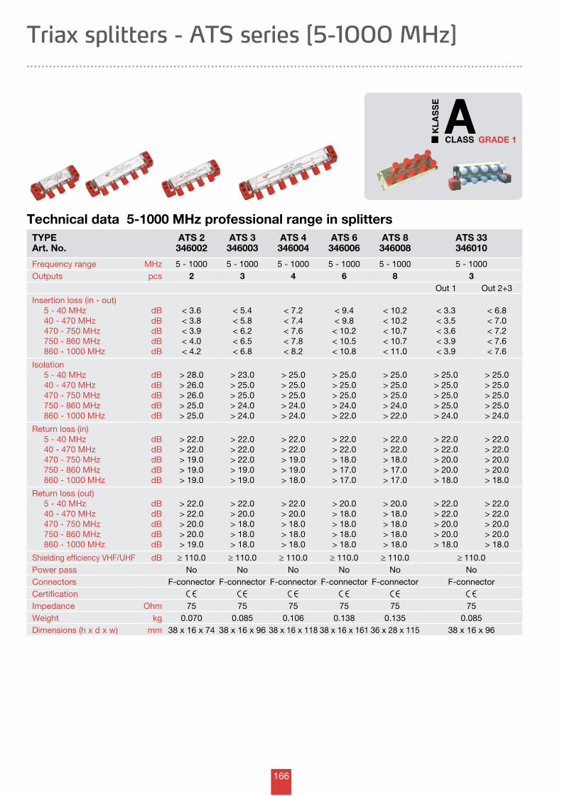
166
GRADE 1
Triax splitters - ATS series [5-1000 MHz]
TYPEArt. No.
ATS 2346002
ATS 3346003
ATS 4346004
ATS 6346006
ATS 8346008
ATS 33346010
Frequency range MHz 5 - 1000 5 - 1000 5 - 1000 5 - 1000 5 - 1000 5 - 1000Outputs pcs 2 3 4 6 8 3
Out 1 Out 2+3Insertion loss (in - out) 5 - 40 MHz 40 - 470 MHz 470 - 750 MHz 750 - 860 MHz 860 - 1000 MHz
dBdBdBdBdB
< 3.6< 3.8< 3.9< 4.0< 4.2
< 5.4< 5.8< 6.2< 6.5< 6.8
< 7.2< 7.4< 7.6< 7.8< 8.2
< 9.4< 9.8
< 10.2< 10.5< 10.8
< 10.2< 10.2< 10.7< 10.7< 11.0
< 3.3< 3.5< 3.6< 3.9< 3.9
< 6.8< 7.0< 7.2< 7.6< 7.6
Isolation 5 - 40 MHz 40 - 470 MHz 470 - 750 MHz 750 - 860 MHz 860 - 1000 MHz
dBdBdBdBdB
> 28.0> 26.0> 26.0> 25.0> 25.0
> 23.0> 25.0> 25.0> 24.0> 24.0
> 25.0> 25.0> 25.0> 24.0> 24.0
> 25.0> 25.0> 25.0> 24.0> 22.0
> 25.0> 25.0> 25.0> 24.0> 22.0
> 25.0> 25.0> 25.0> 25.0> 24.0
> 25.0> 25.0> 25.0> 25.0> 24.0
Return loss (in) 5 - 40 MHz 40 - 470 MHz 470 - 750 MHz 750 - 860 MHz 860 - 1000 MHz
dBdBdBdBdB
> 22.0> 22.0> 19.0> 19.0> 19.0
> 22.0> 22.0> 22.0> 19.0> 19.0
> 22.0> 22.0> 19.0> 19.0> 18.0
> 22.0> 22.0> 18.0> 17.0> 17.0
> 22.0> 22.0> 18.0> 17.0> 17.0
> 22.0> 22.0> 20.0> 20.0> 18.0
> 22.0> 22.0> 20.0> 20.0> 18.0
Return loss (out) 5 - 40 MHz 40 - 470 MHz 470 - 750 MHz 750 - 860 MHz 860 - 1000 MHz
dBdBdBdBdB
> 22.0> 22.0> 20.0> 20.0> 19.0
> 22.0> 20.0> 18.0> 18.0> 18.0
> 22.0> 20.0> 18.0> 18.0> 18.0
> 20.0> 18.0> 18.0> 18.0> 18.0
> 20.0> 18.0> 18.0> 18.0> 18.0
> 22.0> 22.0> 20.0> 20.0> 18.0
> 22.0> 22.0> 20.0> 20.0> 18.0
Shielding efficiency VHF/UHF dB ≥ 110.0 ≥ 110.0 ≥ 110.0 ≥ 110.0 ≥ 110.0 ≥ 110.0Power pass No No No No No NoConnectors F-connector F-connector F-connector F-connector F-connector F-connectorCertificationImpedance Ohm 75 75 75 75 75 75Weight kg 0.070 0.085 0.106 0.138 0.135 0.085Dimensions (h x d x w) mm 38 x 16 x 74 38 x 16 x 96 38 x 16 x 118 38 x 16 x 161 36 x 28 x 115 38 x 16 x 96
Technical data 5-1000 MHz professional range in splitters
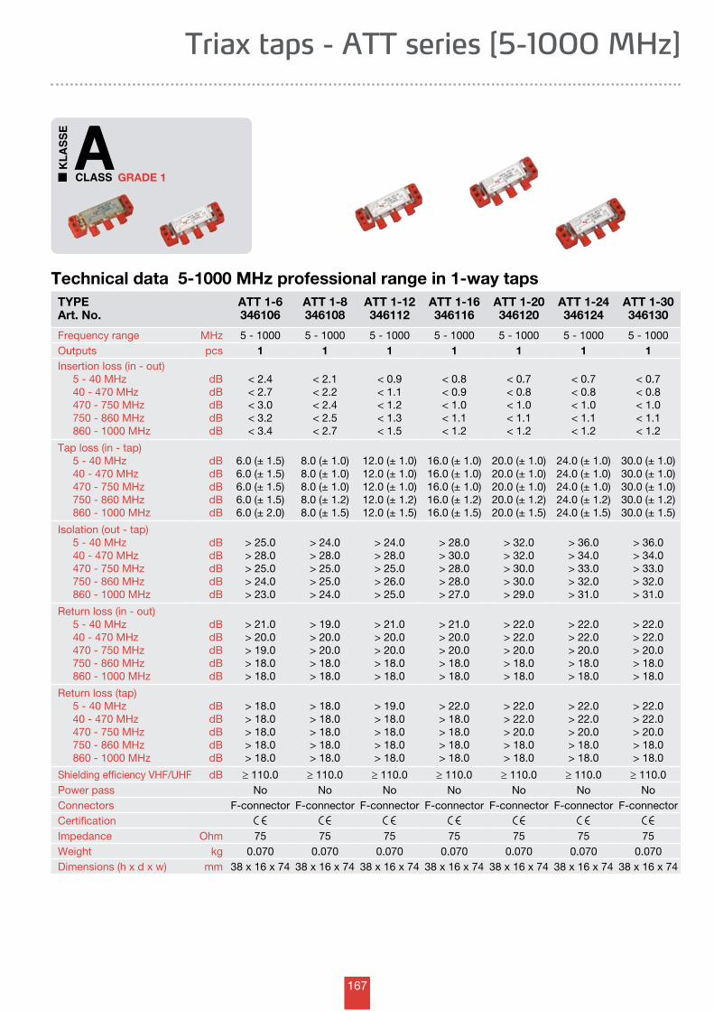
167
GRADE 1
Technical data 5-1000 MHz professional range in 1-way tapsTYPEArt. No.
ATT 1-6346106
ATT 1-8346108
ATT 1-12346112
ATT 1-16346116
ATT 1-20346120
ATT 1-24346124
ATT 1-30346130
Frequency range MHz 5 - 1000 5 - 1000 5 - 1000 5 - 1000 5 - 1000 5 - 1000 5 - 1000Outputs pcs 1 1 1 1 1 1 1Insertion loss (in - out) 5 - 40 MHz 40 - 470 MHz 470 - 750 MHz 750 - 860 MHz 860 - 1000 MHz
dBdBdBdBdB
< 2.4< 2.7< 3.0< 3.2< 3.4
< 2.1< 2.2< 2.4< 2.5< 2.7
< 0.9< 1.1< 1.2< 1.3< 1.5
< 0.8< 0.9< 1.0< 1.1< 1.2
< 0.7< 0.8< 1.0< 1.1< 1.2
< 0.7< 0.8< 1.0< 1.1< 1.2
< 0.7< 0.8< 1.0< 1.1< 1.2
Tap loss (in - tap) 5 - 40 MHz 40 - 470 MHz 470 - 750 MHz 750 - 860 MHz 860 - 1000 MHz
dBdBdBdBdB
6.0 (± 1.5)6.0 (± 1.5)6.0 (± 1.5)6.0 (± 1.5)6.0 (± 2.0)
8.0 (± 1.0)8.0 (± 1.0)8.0 (± 1.0)8.0 (± 1.2)8.0 (± 1.5)
12.0 (± 1.0)12.0 (± 1.0)12.0 (± 1.0)12.0 (± 1.2)12.0 (± 1.5)
16.0 (± 1.0)16.0 (± 1.0)16.0 (± 1.0)16.0 (± 1.2)16.0 (± 1.5)
20.0 (± 1.0)20.0 (± 1.0)20.0 (± 1.0)20.0 (± 1.2)20.0 (± 1.5)
24.0 (± 1.0)24.0 (± 1.0)24.0 (± 1.0)24.0 (± 1.2)24.0 (± 1.5)
30.0 (± 1.0)30.0 (± 1.0)30.0 (± 1.0)30.0 (± 1.2)30.0 (± 1.5)
Isolation (out - tap) 5 - 40 MHz 40 - 470 MHz 470 - 750 MHz 750 - 860 MHz 860 - 1000 MHz
dBdBdBdBdB
> 25.0> 28.0> 25.0> 24.0> 23.0
> 24.0> 28.0> 25.0> 25.0> 24.0
> 24.0> 28.0> 25.0> 26.0> 25.0
> 28.0> 30.0> 28.0> 28.0> 27.0
> 32.0> 32.0> 30.0> 30.0> 29.0
> 36.0> 34.0> 33.0> 32.0> 31.0
> 36.0> 34.0> 33.0> 32.0> 31.0
Return loss (in - out) 5 - 40 MHz 40 - 470 MHz 470 - 750 MHz 750 - 860 MHz 860 - 1000 MHz
dBdBdBdBdB
> 21.0> 20.0> 19.0> 18.0> 18.0
> 19.0> 20.0> 20.0> 18.0> 18.0
> 21.0> 20.0> 20.0> 18.0> 18.0
> 21.0> 20.0> 20.0> 18.0> 18.0
> 22.0> 22.0> 20.0> 18.0> 18.0
> 22.0> 22.0> 20.0> 18.0> 18.0
> 22.0> 22.0> 20.0> 18.0> 18.0
Return loss (tap) 5 - 40 MHz 40 - 470 MHz 470 - 750 MHz 750 - 860 MHz 860 - 1000 MHz
dBdBdBdBdB
> 18.0> 18.0> 18.0> 18.0> 18.0
> 18.0> 18.0> 18.0> 18.0> 18.0
> 19.0> 18.0> 18.0> 18.0> 18.0
> 22.0> 18.0> 18.0> 18.0> 18.0
> 22.0> 22.0> 20.0> 18.0> 18.0
> 22.0> 22.0> 20.0> 18.0> 18.0
> 22.0> 22.0> 20.0> 18.0> 18.0
Shielding efficiency VHF/UHF dB ≥ 110.0 ≥ 110.0 ≥ 110.0 ≥ 110.0 ≥ 110.0 ≥ 110.0 ≥ 110.0Power pass No No No No No No NoConnectors F-connector F-connector F-connector F-connector F-connector F-connector F-connectorCertificationImpedance Ohm 75 75 75 75 75 75 75Weight kg 0.070 0.070 0.070 0.070 0.070 0.070 0.070Dimensions (h x d x w) mm 38 x 16 x 74 38 x 16 x 74 38 x 16 x 74 38 x 16 x 74 38 x 16 x 74 38 x 16 x 74 38 x 16 x 74
Triax taps - ATT series [5-1000 MHz]
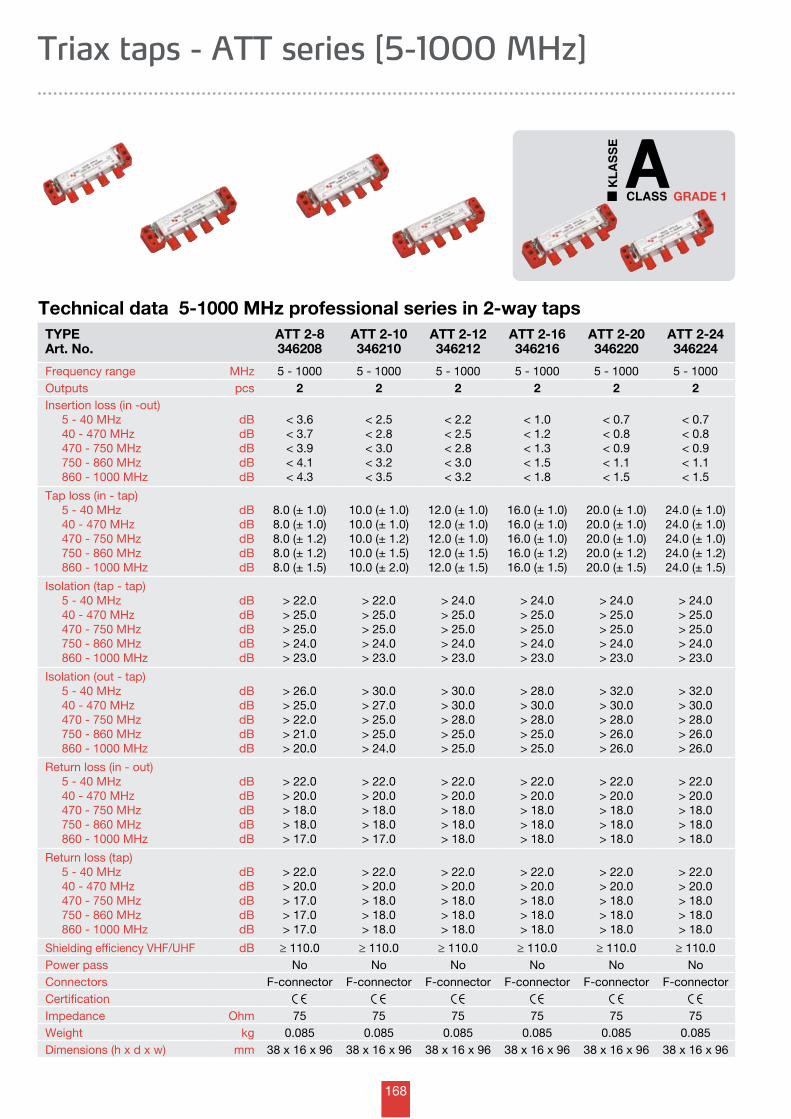
168
GRADE 1
TYPEArt. No.
ATT 2-8346208
ATT 2-10346210
ATT 2-12346212
ATT 2-16346216
ATT 2-20346220
ATT 2-24346224
Frequency range MHz 5 - 1000 5 - 1000 5 - 1000 5 - 1000 5 - 1000 5 - 1000Outputs pcs 2 2 2 2 2 2Insertion loss (in -out) 5 - 40 MHz 40 - 470 MHz 470 - 750 MHz 750 - 860 MHz 860 - 1000 MHz
dBdBdBdBdB
< 3.6< 3.7< 3.9< 4.1< 4.3
< 2.5< 2.8< 3.0< 3.2< 3.5
< 2.2< 2.5< 2.8< 3.0< 3.2
< 1.0< 1.2< 1.3< 1.5< 1.8
< 0.7< 0.8< 0.9< 1.1< 1.5
< 0.7< 0.8< 0.9< 1.1< 1.5
Tap loss (in - tap) 5 - 40 MHz 40 - 470 MHz 470 - 750 MHz 750 - 860 MHz 860 - 1000 MHz
dBdBdBdBdB
8.0 (± 1.0)8.0 (± 1.0)8.0 (± 1.2)8.0 (± 1.2)8.0 (± 1.5)
10.0 (± 1.0)10.0 (± 1.0)10.0 (± 1.2)10.0 (± 1.5)10.0 (± 2.0)
12.0 (± 1.0)12.0 (± 1.0)12.0 (± 1.0)12.0 (± 1.5)12.0 (± 1.5)
16.0 (± 1.0)16.0 (± 1.0)16.0 (± 1.0)16.0 (± 1.2)16.0 (± 1.5)
20.0 (± 1.0)20.0 (± 1.0)20.0 (± 1.0)20.0 (± 1.2)20.0 (± 1.5)
24.0 (± 1.0)24.0 (± 1.0)24.0 (± 1.0)24.0 (± 1.2)24.0 (± 1.5)
Isolation (tap - tap) 5 - 40 MHz 40 - 470 MHz 470 - 750 MHz 750 - 860 MHz 860 - 1000 MHz
dBdBdBdBdB
> 22.0> 25.0> 25.0> 24.0> 23.0
> 22.0> 25.0> 25.0> 24.0> 23.0
> 24.0> 25.0> 25.0> 24.0> 23.0
> 24.0> 25.0> 25.0> 24.0> 23.0
> 24.0> 25.0> 25.0> 24.0> 23.0
> 24.0> 25.0> 25.0> 24.0> 23.0
Isolation (out - tap) 5 - 40 MHz 40 - 470 MHz 470 - 750 MHz 750 - 860 MHz 860 - 1000 MHz
dBdBdBdBdB
> 26.0> 25.0> 22.0> 21.0> 20.0
> 30.0> 27.0> 25.0> 25.0> 24.0
> 30.0> 30.0> 28.0> 25.0> 25.0
> 28.0> 30.0> 28.0> 25.0> 25.0
> 32.0> 30.0> 28.0> 26.0> 26.0
> 32.0> 30.0> 28.0> 26.0> 26.0
Return loss (in - out) 5 - 40 MHz 40 - 470 MHz 470 - 750 MHz 750 - 860 MHz 860 - 1000 MHz
dBdBdBdBdB
> 22.0> 20.0> 18.0> 18.0> 17.0
> 22.0> 20.0> 18.0> 18.0> 17.0
> 22.0> 20.0> 18.0> 18.0> 18.0
> 22.0> 20.0> 18.0> 18.0> 18.0
> 22.0> 20.0> 18.0> 18.0> 18.0
> 22.0> 20.0> 18.0> 18.0> 18.0
Return loss (tap) 5 - 40 MHz 40 - 470 MHz 470 - 750 MHz 750 - 860 MHz 860 - 1000 MHz
dBdBdBdBdB
> 22.0> 20.0> 17.0> 17.0> 17.0
> 22.0> 20.0> 18.0> 18.0> 18.0
> 22.0> 20.0> 18.0> 18.0> 18.0
> 22.0> 20.0> 18.0> 18.0> 18.0
> 22.0> 20.0> 18.0> 18.0> 18.0
> 22.0> 20.0> 18.0> 18.0> 18.0
Shielding efficiency VHF/UHF dB ≥ 110.0 ≥ 110.0 ≥ 110.0 ≥ 110.0 ≥ 110.0 ≥ 110.0Power pass No No No No No NoConnectors F-connector F-connector F-connector F-connector F-connector F-connectorCertificationImpedance Ohm 75 75 75 75 75 75Weight kg 0.085 0.085 0.085 0.085 0.085 0.085Dimensions (h x d x w) mm 38 x 16 x 96 38 x 16 x 96 38 x 16 x 96 38 x 16 x 96 38 x 16 x 96 38 x 16 x 96
Technical data 5-1000 MHz professional series in 2-way taps
Triax taps - ATT series [5-1000 MHz]
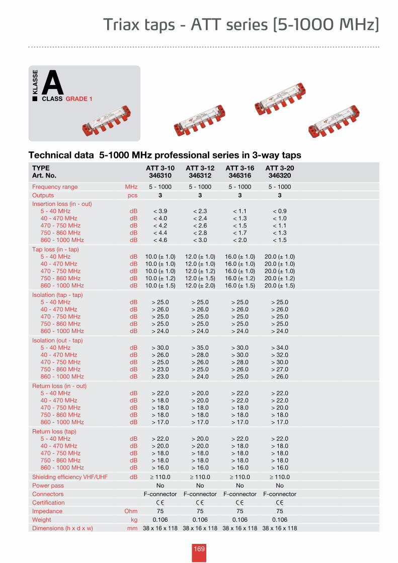
169
GRADE 1
Technical data 5-1000 MHz professional series in 3-way tapsTYPEArt. No.
ATT 3-10346310
ATT 3-12346312
ATT 3-16346316
ATT 3-20346320
Frequency range MHz 5 - 1000 5 - 1000 5 - 1000 5 - 1000Outputs pcs 3 3 3 3Insertion loss (in - out) 5 - 40 MHz 40 - 470 MHz 470 - 750 MHz 750 - 860 MHz 860 - 1000 MHz
dBdBdBdBdB
< 3.9< 4.0< 4.2< 4.4< 4.6
< 2.3< 2.4< 2.6< 2.8< 3.0
< 1.1< 1.3< 1.5< 1.7< 2.0
< 0.9< 1.0< 1.1< 1.3< 1.5
Tap loss (in - tap) 5 - 40 MHz 40 - 470 MHz 470 - 750 MHz 750 - 860 MHz 860 - 1000 MHz
dBdBdBdBdB
10.0 (± 1.0)10.0 (± 1.0)10.0 (± 1.0)10.0 (± 1.2)10.0 (± 1.5)
12.0 (± 1.0)12.0 (± 1.0)12.0 (± 1.2)12.0 (± 1.5)12.0 (± 2.0)
16.0 (± 1.0)16.0 (± 1.0)16.0 (± 1.0)16.0 (± 1.2)16.0 (± 1.5)
20.0 (± 1.0)20.0 (± 1.0)20.0 (± 1.0)20.0 (± 1.2)20.0 (± 1.5)
Isolation (tap - tap) 5 - 40 MHz 40 - 470 MHz 470 - 750 MHz 750 - 860 MHz 860 - 1000 MHz
dBdBdBdBdB
> 25.0> 26.0> 25.0> 25.0> 24.0
> 25.0> 26.0> 25.0> 25.0> 24.0
> 25.0> 26.0> 25.0> 25.0> 24.0
> 25.0> 26.0> 25.0> 25.0> 24.0
Isolation (out - tap) 5 - 40 MHz 40 - 470 MHz 470 - 750 MHz 750 - 860 MHz 860 - 1000 MHz
dBdBdBdBdB
> 30.0> 26.0> 25.0> 23.0> 23.0
> 35.0> 28.0> 26.0> 25.0> 24.0
> 30.0> 30.0> 28.0> 26.0> 25.0
> 34.0> 32.0> 30.0> 27.0> 26.0
Return loss (in - out) 5 - 40 MHz 40 - 470 MHz 470 - 750 MHz 750 - 860 MHz 860 - 1000 MHz
dBdBdBdBdB
> 22.0> 18.0> 18.0> 18.0> 17.0
> 20.0> 20.0> 18.0> 18.0> 17.0
> 22.0> 22.0> 18.0> 18.0> 17.0
> 22.0> 22.0> 20.0> 18.0> 17.0
Return loss (tap) 5 - 40 MHz 40 - 470 MHz 470 - 750 MHz 750 - 860 MHz 860 - 1000 MHz
dBdBdBdBdB
> 22.0> 20.0> 18.0> 18.0> 16.0
> 20.0> 20.0> 18.0> 18.0> 16.0
> 22.0> 18.0> 18.0> 18.0> 16.0
> 22.0> 18.0> 18.0> 18.0> 16.0
Shielding efficiency VHF/UHF dB ≥ 110.0 ≥ 110.0 ≥ 110.0 ≥ 110.0Power pass No No No NoConnectors F-connector F-connector F-connector F-connectorCertificationImpedance Ohm 75 75 75 75Weight kg 0.106 0.106 0.106 0.106Dimensions (h x d x w) mm 38 x 16 x 118 38 x 16 x 118 38 x 16 x 118 38 x 16 x 118
Triax taps - ATT series [5-1000 MHz]
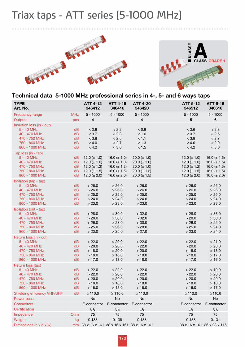
170
GRADE 1
TYPEArt. No.
ATT 4-12346412
ATT 4-16346416
ATT 4-20346420
ATT 5-12346512
ATT 6-16346616
Frequency range MHz 5 - 1000 5 - 1000 5 - 1000 5 - 1000 5 - 1000Outputs pcs 4 4 4 5 6Insertion loss (in - out) 5 - 40 MHz 40 - 470 MHz 470 - 750 MHz 750 - 860 MHz 860 - 1000 MHz
dBdBdBdBdB
< 3.6< 3.7< 3.8< 4.0< 4.2
< 2.2< 2.3< 2.5< 2.7< 3.0
< 0.9< 1.0< 1.1< 1.3< 1.5
< 3.6< 3.7< 3.8< 4.0< 4.2
< 2.3< 2.5< 2.7< 2.9< 3.0
Tap loss (in - tap) 5 - 40 MHz 40 - 470 MHz 470 - 750 MHz 750 - 860 MHz 860 - 1000 MHz
dBdBdBdBdB
12.0 (± 1.0)12.0 (± 1.0)12.0 (± 1.2)12.0 (± 1.5)12.0 (± 2.0)
16.0 (± 1.0)16.0 (± 1.0)16.0 (± 1.2)16.0 (± 1.5)16.0 (± 2.0)
20.0 (± 1.0)20.0 (± 1.0)20.0 (± 1.0)20.0 (± 1.2)20.0 (± 1.5)
12.0 (± 1.0)12.0 (± 1.0)12.0 (± 1.2)12.0 (± 1.5)12.0 (± 2.0)
16.0 (± 1.5)16.0 (± 1.5)16.0 (± 1.5)16.0 (± 1.5)16.0 (± 2.0)
Isolation (tap - tap) 5 - 40 MHz 40 - 470 MHz 470 - 750 MHz 750 - 860 MHz 860 - 1000 MHz
dBdBdBdBdB
> 26.0> 26.0> 25.0> 24.0> 23.0
> 26.0> 26.0> 25.0> 24.0> 23.0
> 26.0> 26.0> 25.0> 24.0> 23.0
> 26.0> 26.0> 25.0> 24.0> 23.0
> 26.0> 26.0> 25.0> 24.0> 23.0
Isolation (out - tap) 5 - 40 MHz 40 - 470 MHz 470 - 750 MHz 750 - 860 MHz 860 - 1000 MHz
dBdBdBdBdB
> 28.0> 28.0> 26.0> 25.0> 23.0
> 30.0> 30.0> 28.0> 26.0> 25.0
> 32.0> 32.0> 30.0> 28.0> 27.0
> 28.0> 28.0> 26.0> 25.0> 23.0
> 36.0> 30.0> 25.0> 24.0> 24.0
Return loss (in - out) 5 - 40 MHz 40 - 470 MHz 470 - 750 MHz 750 - 860 MHz 860 - 1000 MHz
dBdBdBdBdB
> 22.0> 20.0> 18.0> 18.0> 17.0
> 20.0> 20.0> 20.0> 18.0> 18.0
> 22.0> 22.0> 20.0> 18.0> 18.0
> 22.0> 20.0> 18.0> 18.0> 17.0
> 21.0> 20.0> 18.0> 17.0> 16.0
Return loss (tap) 5 - 40 MHz 40 - 470 MHz 470 - 750 MHz 750 - 860 MHz 860 - 1000 MHz
dBdBdBdBdB
> 22.0> 22.0> 20.0> 18.0> 18.0
> 22.0> 20.0> 20.0> 18.0> 18.0
> 22.0> 22.0> 20.0> 18.0> 18.0
> 22.0> 22.0> 20.0> 18.0> 18.0
> 19.0> 20.0> 20.0> 18.0> 17.0
Shielding efficiency VHF/UHF dB ≥ 110.0 ≥ 110.0 ≥ 110.0 ≥ 110.0 ≥ 110.0Power pass No No No No NoConnectors F-connector F-connector F-connector F-connector F-connectorCertificationImpedance Ohm 75 75 75 75 75Weight kg 0.138 0.138 0.138 0.138 0.131Dimensions (h x d x w) mm 38 x 16 x 161 38 x 16 x 161 38 x 16 x 161 38 x 16 x 161 36 x 28 x 115
Technical data 5-1000 MHz professional series in 4-, 5- and 6 ways taps
Triax taps - ATT series [5-1000 MHz]
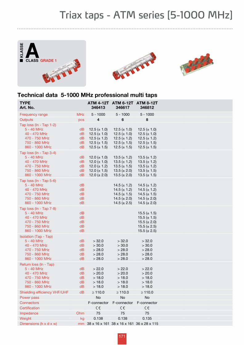
171
GRADE 1
Triax taps - ATM series [5-1000 MHz]
TYPEArt. No.
ATM 4-12T346413
ATM 6-12T346617
ATM 8-12T346812
Frequency range MHz 5 - 1000 5 - 1000 5 - 1000Outputs pcs 4 6 8Tap loss (In - Tap 1-2) 5 - 40 MHz 40 - 470 MHz 470 - 750 MHz 750 - 860 MHz 860 - 1000 MHz
dBdBdBdBdB
12.5 (± 1.0)12.5 (± 1.0)12.5 (± 1.2)12.5 (± 1.5)12.5 (± 1.5)
12.5 (± 1.0)12.5 (± 1.0)12.5 (± 1.2)12.5 (± 1.5)12.5 (± 1.5)
12.5 (± 1.0)12.5 (± 1.0)12.5 (± 1.2)12.5 (± 1.5)12.5 (± 1.5)
Tap loss (In - Tap 3-4) 5 - 40 MHz 40 - 470 MHz 470 - 750 MHz 750 - 860 MHz 860 - 1000 MHz
dBdBdBdBdB
12.0 (± 1.0)12.0 (± 1.0)12.0 (± 1.2)12.0 (± 1.5)12.0 (± 2.0)
13.5 (± 1.2)13.5 (± 1.2)13.5 (± 1.5)13.5 (± 2.0)13.5 (± 2.0)
13.5 (± 1.2)13.5 (± 1.2)13.5 (± 1.2)13.5 (± 1.5)13.5 (± 1.5)
Tap loss (In - Tap 5-6) 5 - 40 MHz 40 - 470 MHz 470 - 750 MHz 750 - 860 MHz 860 - 1000 MHz
dBdBdBdBdB
14.5 (± 1.2)14.5 (± 1.2)14.5 (± 1.5)14.5 (± 2.0)14.5 (± 2.5)
14.5 (± 1.2)14.5 (± 1.2)14.5 (± 1.5)14.5 (± 2.0)14.5 (± 2.0)
Tap loss (In - Tap 7-8) 5 - 40 MHz 40 - 470 MHz 470 - 750 MHz 750 - 860 MHz 860 - 1000 MHz
dBdBdBdBdB
15.5 (± 1.5)15.5 (± 1.5)15.5 (± 2.0)15.5 (± 2.5)15.5 (± 2.5)
Isolation (Tap - Tap) 5 - 40 MHz 40 - 470 MHz 470 - 750 MHz 750 - 860 MHz 860 - 1000 MHz
dBdBdBdBdB
> 32.0> 30.0> 28.0> 28.0> 28.0
> 32.0> 30.0> 28.0> 28.0> 28.0
> 32.0> 30.0> 28.0> 28.0> 28.0
Return loss (In - Tap) 5 - 40 MHz 40 - 470 MHz 470 - 750 MHz 750 - 860 MHz 860 - 1000 MHz
dBdBdBdBdB
> 22.0> 20.0> 18.0> 18.0> 18.0
> 22.0> 20.0> 18.0> 18.0> 18.0
> 22.0> 20.0> 18.0> 18.0> 18.0
Shielding efficiency VHF/UHF dB ≥ 110.0 ≥ 110.0 ≥ 110.0Power pass No No NoConnectors F-connector F-connector F-connectorCertificationImpedance Ohm 75 75 75Weight kg 0.138 0.138 0.135Dimensions (h x d x w) mm 38 x 16 x 161 38 x 16 x 161 36 x 28 x 115
Technical data 5-1000 MHz professional multi taps
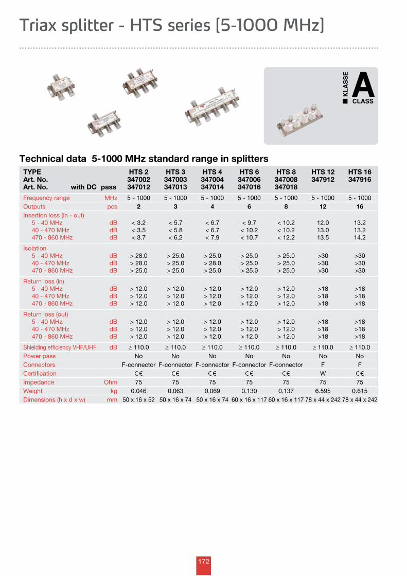
172
TYPEArt. No.Art. No. with DC pass
HTS 2347002347012
HTS 3347003347013
HTS 4347004347014
HTS 6347006347016
HTS 8347008347018
HTS 12347912
HTS 16347916
Frequency range MHz 5 - 1000 5 - 1000 5 - 1000 5 - 1000 5 - 1000 5 - 1000 5 - 1000Outputs pcs 2 3 4 6 8 12 16Insertion loss (in - out) 5 - 40 MHz 40 - 470 MHz 470 - 860 MHz
dBdBdB
< 3.2< 3.5< 3.7
< 5.7< 5.8< 6.2
< 6.7< 6.7< 7.9
< 9.7< 10.2< 10.7
< 10.2< 10.2< 12.2
12.013.013.5
13.213.214.2
Isolation 5 - 40 MHz 40 - 470 MHz 470 - 860 MHz
dBdBdB
> 28.0> 28.0> 25.0
> 25.0> 25.0> 25.0
> 25.0> 28.0> 25.0
> 25.0> 25.0> 25.0
> 25.0> 25.0> 25.0
>30>30>30
>30>30>30
Return loss (in) 5 - 40 MHz 40 - 470 MHz 470 - 860 MHz
dBdBdB
> 12.0> 12.0> 12.0
> 12.0> 12.0> 12.0
> 12.0> 12.0> 12.0
> 12.0> 12.0> 12.0
> 12.0> 12.0> 12.0
>18>18>18
>18>18>18
Return loss (out) 5 - 40 MHz 40 - 470 MHz 470 - 860 MHz
dBdBdB
> 12.0> 12.0> 12.0
> 12.0> 12.0> 12.0
> 12.0> 12.0> 12.0
> 12.0> 12.0> 12.0
> 12.0> 12.0> 12.0
>18>18>18
>18>18>18
Shielding efficiency VHF/UHF dB ≥ 110.0 ≥ 110.0 ≥ 110.0 ≥ 110.0 ≥ 110.0 ≥ 110.0 ≥ 110.0Power pass No No No No No No NoConnectors F-connector F-connector F-connector F-connector F-connector F FCertification WImpedance Ohm 75 75 75 75 75 75 75Weight kg 0.046 0.063 0.069 0.130 0.137 6.595 0.615Dimensions (h x d x w) mm 50 x 16 x 52 50 x 16 x 74 50 x 16 x 74 60 x 16 x 117 60 x 16 x 117 78 x 44 x 242 78 x 44 x 242
Technical data 5-1000 MHz standard range in splitters
Triax splitter - HTS series [5-1000 MHz]
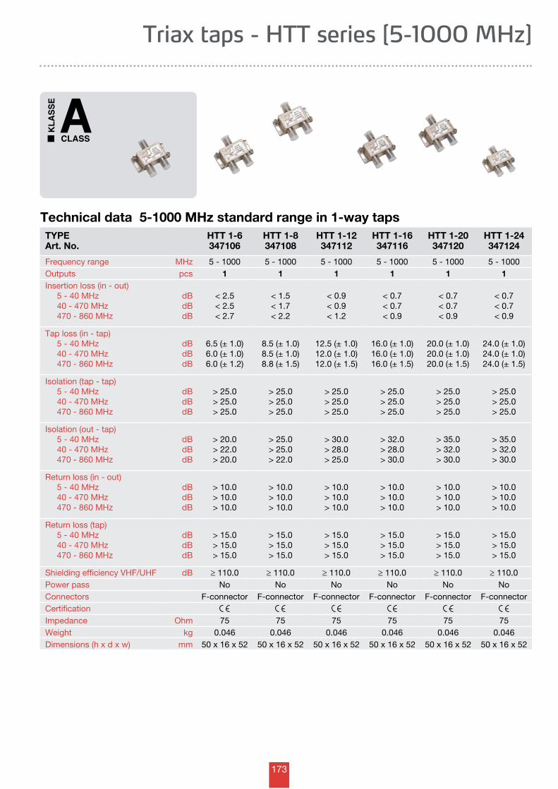
173
Triax taps - HTT series [5-1000 MHz]
TYPEArt. No.
HTT 1-6347106
HTT 1-8347108
HTT 1-12347112
HTT 1-16347116
HTT 1-20347120
HTT 1-24347124
Frequency range MHz 5 - 1000 5 - 1000 5 - 1000 5 - 1000 5 - 1000 5 - 1000Outputs pcs 1 1 1 1 1 1Insertion loss (in - out) 5 - 40 MHz 40 - 470 MHz 470 - 860 MHz
dBdBdB
< 2.5< 2.5< 2.7
< 1.5< 1.7< 2.2
< 0.9< 0.9< 1.2
< 0.7< 0.7< 0.9
< 0.7< 0.7< 0.9
< 0.7< 0.7< 0.9
Tap loss (in - tap) 5 - 40 MHz 40 - 470 MHz 470 - 860 MHz
dBdBdB
6.5 (± 1.0)6.0 (± 1.0)6.0 (± 1.2)
8.5 (± 1.0)8.5 (± 1.0)8.8 (± 1.5)
12.5 (± 1.0)12.0 (± 1.0)12.0 (± 1.5)
16.0 (± 1.0)16.0 (± 1.0)16.0 (± 1.5)
20.0 (± 1.0)20.0 (± 1.0)20.0 (± 1.5)
24.0 (± 1.0)24.0 (± 1.0)24.0 (± 1.5)
Isolation (tap - tap) 5 - 40 MHz 40 - 470 MHz 470 - 860 MHz
dBdBdB
> 25.0> 25.0> 25.0
> 25.0> 25.0> 25.0
> 25.0> 25.0> 25.0
> 25.0> 25.0> 25.0
> 25.0> 25.0> 25.0
> 25.0> 25.0> 25.0
Isolation (out - tap) 5 - 40 MHz 40 - 470 MHz 470 - 860 MHz
dBdBdB
> 20.0> 22.0> 20.0
> 25.0> 25.0> 22.0
> 30.0> 28.0> 25.0
> 32.0> 28.0> 30.0
> 35.0> 32.0> 30.0
> 35.0> 32.0> 30.0
Return loss (in - out) 5 - 40 MHz 40 - 470 MHz 470 - 860 MHz
dBdBdB
> 10.0> 10.0> 10.0
> 10.0> 10.0> 10.0
> 10.0> 10.0> 10.0
> 10.0> 10.0> 10.0
> 10.0> 10.0> 10.0
> 10.0> 10.0> 10.0
Return loss (tap) 5 - 40 MHz 40 - 470 MHz 470 - 860 MHz
dBdBdB
> 15.0> 15.0> 15.0
> 15.0> 15.0> 15.0
> 15.0> 15.0> 15.0
> 15.0> 15.0> 15.0
> 15.0> 15.0> 15.0
> 15.0> 15.0> 15.0
Shielding efficiency VHF/UHF dB ≥ 110.0 ≥ 110.0 ≥ 110.0 ≥ 110.0 ≥ 110.0 ≥ 110.0Power pass No No No No No NoConnectors F-connector F-connector F-connector F-connector F-connector F-connectorCertificationImpedance Ohm 75 75 75 75 75 75Weight kg 0.046 0.046 0.046 0.046 0.046 0.046Dimensions (h x d x w) mm 50 x 16 x 52 50 x 16 x 52 50 x 16 x 52 50 x 16 x 52 50 x 16 x 52 50 x 16 x 52
Technical data 5-1000 MHz standard range in 1-way taps
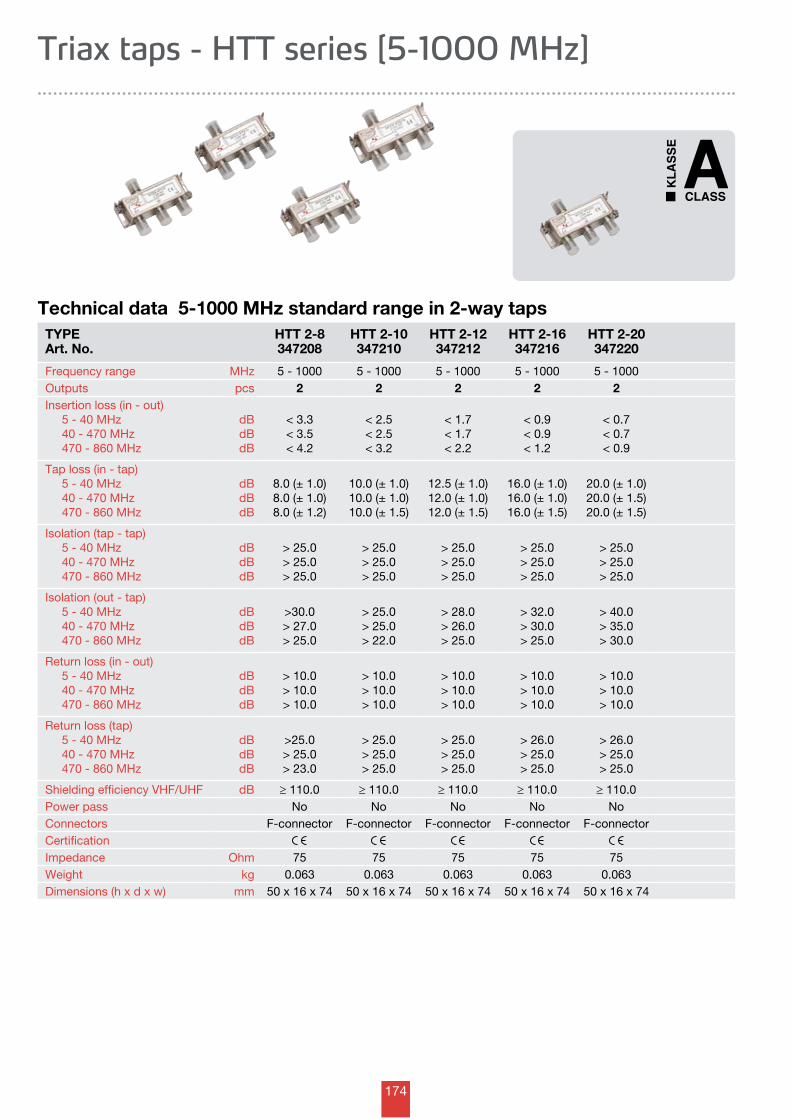
174
Technical data 5-1000 MHz standard range in 2-way tapsTYPEArt. No.
HTT 2-8347208
HTT 2-10347210
HTT 2-12347212
HTT 2-16347216
HTT 2-20347220
Frequency range MHz 5 - 1000 5 - 1000 5 - 1000 5 - 1000 5 - 1000Outputs pcs 2 2 2 2 2Insertion loss (in - out) 5 - 40 MHz 40 - 470 MHz 470 - 860 MHz
dBdBdB
< 3.3< 3.5< 4.2
< 2.5< 2.5< 3.2
< 1.7< 1.7< 2.2
< 0.9< 0.9< 1.2
< 0.7< 0.7< 0.9
Tap loss (in - tap) 5 - 40 MHz 40 - 470 MHz 470 - 860 MHz
dBdBdB
8.0 (± 1.0)8.0 (± 1.0)8.0 (± 1.2)
10.0 (± 1.0)10.0 (± 1.0)10.0 (± 1.5)
12.5 (± 1.0)12.0 (± 1.0)12.0 (± 1.5)
16.0 (± 1.0)16.0 (± 1.0)16.0 (± 1.5)
20.0 (± 1.0)20.0 (± 1.5)20.0 (± 1.5)
Isolation (tap - tap) 5 - 40 MHz 40 - 470 MHz 470 - 860 MHz
dBdBdB
> 25.0> 25.0> 25.0
> 25.0> 25.0> 25.0
> 25.0> 25.0> 25.0
> 25.0> 25.0> 25.0
> 25.0> 25.0> 25.0
Isolation (out - tap) 5 - 40 MHz 40 - 470 MHz 470 - 860 MHz
dBdBdB
>30.0> 27.0> 25.0
> 25.0> 25.0> 22.0
> 28.0> 26.0> 25.0
> 32.0> 30.0> 25.0
> 40.0> 35.0> 30.0
Return loss (in - out) 5 - 40 MHz 40 - 470 MHz 470 - 860 MHz
dBdBdB
> 10.0> 10.0> 10.0
> 10.0> 10.0> 10.0
> 10.0> 10.0> 10.0
> 10.0> 10.0> 10.0
> 10.0> 10.0> 10.0
Return loss (tap) 5 - 40 MHz 40 - 470 MHz 470 - 860 MHz
dBdBdB
>25.0> 25.0> 23.0
> 25.0> 25.0> 25.0
> 25.0> 25.0> 25.0
> 26.0> 25.0> 25.0
> 26.0> 25.0> 25.0
Shielding efficiency VHF/UHF dB ≥ 110.0 ≥ 110.0 ≥ 110.0 ≥ 110.0 ≥ 110.0Power pass No No No No NoConnectors F-connector F-connector F-connector F-connector F-connectorCertificationImpedance Ohm 75 75 75 75 75Weight kg 0.063 0.063 0.063 0.063 0.063Dimensions (h x d x w) mm 50 x 16 x 74 50 x 16 x 74 50 x 16 x 74 50 x 16 x 74 50 x 16 x 74
Triax taps - HTT series [5-1000 MHz]
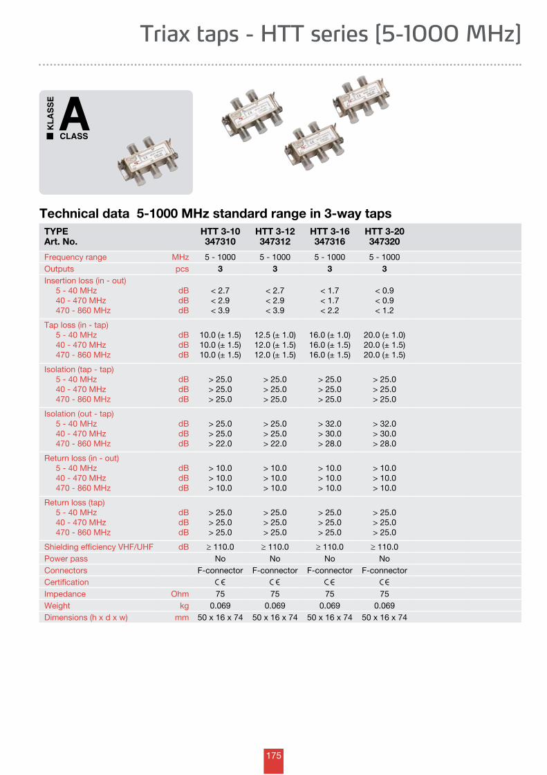
175
Technical data 5-1000 MHz standard range in 3-way tapsTYPEArt. No.
HTT 3-10347310
HTT 3-12347312
HTT 3-16347316
HTT 3-20347320
Frequency range MHz 5 - 1000 5 - 1000 5 - 1000 5 - 1000Outputs pcs 3 3 3 3Insertion loss (in - out) 5 - 40 MHz 40 - 470 MHz 470 - 860 MHz
dBdBdB
< 2.7< 2.9< 3.9
< 2.7< 2.9< 3.9
< 1.7< 1.7< 2.2
< 0.9< 0.9< 1.2
Tap loss (in - tap) 5 - 40 MHz 40 - 470 MHz 470 - 860 MHz
dBdBdB
10.0 (± 1.5)10.0 (± 1.5)10.0 (± 1.5)
12.5 (± 1.0)12.0 (± 1.5)12.0 (± 1.5)
16.0 (± 1.0)16.0 (± 1.5)16.0 (± 1.5)
20.0 (± 1.0)20.0 (± 1.5)20.0 (± 1.5)
Isolation (tap - tap) 5 - 40 MHz 40 - 470 MHz 470 - 860 MHz
dBdBdB
> 25.0> 25.0> 25.0
> 25.0> 25.0> 25.0
> 25.0> 25.0> 25.0
> 25.0> 25.0> 25.0
Isolation (out - tap) 5 - 40 MHz 40 - 470 MHz 470 - 860 MHz
dBdBdB
> 25.0> 25.0> 22.0
> 25.0> 25.0> 22.0
> 32.0> 30.0> 28.0
> 32.0> 30.0> 28.0
Return loss (in - out) 5 - 40 MHz 40 - 470 MHz 470 - 860 MHz
dBdBdB
> 10.0> 10.0> 10.0
> 10.0> 10.0> 10.0
> 10.0> 10.0> 10.0
> 10.0> 10.0> 10.0
Return loss (tap) 5 - 40 MHz 40 - 470 MHz 470 - 860 MHz
dBdBdB
> 25.0> 25.0> 25.0
> 25.0> 25.0> 25.0
> 25.0> 25.0> 25.0
> 25.0> 25.0> 25.0
Shielding efficiency VHF/UHF dB ≥ 110.0 ≥ 110.0 ≥ 110.0 ≥ 110.0Power pass No No No NoConnectors F-connector F-connector F-connector F-connectorCertificationImpedance Ohm 75 75 75 75Weight kg 0.069 0.069 0.069 0.069Dimensions (h x d x w) mm 50 x 16 x 74 50 x 16 x 74 50 x 16 x 74 50 x 16 x 74
Triax taps - HTT series [5-1000 MHz]
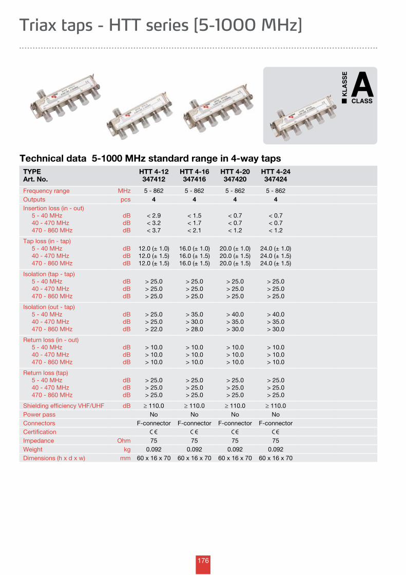
176
Technical data 5-1000 MHz standard range in 4-way tapsTYPEArt. No.
HTT 4-12347412
HTT 4-16347416
HTT 4-20347420
HTT 4-24347424
Frequency range MHz 5 - 862 5 - 862 5 - 862 5 - 862Outputs pcs 4 4 4 4Insertion loss (in - out) 5 - 40 MHz 40 - 470 MHz 470 - 860 MHz
dBdBdB
< 2.9< 3.2< 3.7
< 1.5< 1.7< 2.1
< 0.7< 0.7< 1.2
< 0.7< 0.7< 1.2
Tap loss (in - tap) 5 - 40 MHz 40 - 470 MHz 470 - 860 MHz
dBdBdB
12.0 (± 1.0)12.0 (± 1.5)12.0 (± 1.5)
16.0 (± 1.0)16.0 (± 1.5)16.0 (± 1.5)
20.0 (± 1.0)20.0 (± 1.5)20.0 (± 1.5)
24.0 (± 1.0)24.0 (± 1.5)24.0 (± 1.5)
Isolation (tap - tap) 5 - 40 MHz 40 - 470 MHz 470 - 860 MHz
dBdBdB
> 25.0> 25.0> 25.0
> 25.0> 25.0> 25.0
> 25.0> 25.0> 25.0
> 25.0> 25.0> 25.0
Isolation (out - tap) 5 - 40 MHz 40 - 470 MHz 470 - 860 MHz
dBdBdB
> 25.0> 25.0> 22.0
> 35.0> 30.0> 28.0
> 40.0> 35.0> 30.0
> 40.0> 35.0> 30.0
Return loss (in - out) 5 - 40 MHz 40 - 470 MHz 470 - 860 MHz
dBdBdB
> 10.0> 10.0> 10.0
> 10.0> 10.0> 10.0
> 10.0> 10.0> 10.0
> 10.0> 10.0> 10.0
Return loss (tap) 5 - 40 MHz 40 - 470 MHz 470 - 860 MHz
dBdBdB
> 25.0> 25.0> 25.0
> 25.0> 25.0> 25.0
> 25.0> 25.0> 25.0
> 25.0> 25.0> 25.0
Shielding efficiency VHF/UHF dB ≥ 110.0 ≥ 110.0 ≥ 110.0 ≥ 110.0Power pass No No No NoConnectors F-connector F-connector F-connector F-connectorCertificationImpedance Ohm 75 75 75 75Weight kg 0.092 0.092 0.092 0.092Dimensions (h x d x w) mm 60 x 16 x 70 60 x 16 x 70 60 x 16 x 70 60 x 16 x 70
Triax taps - HTT series [5-1000 MHz]
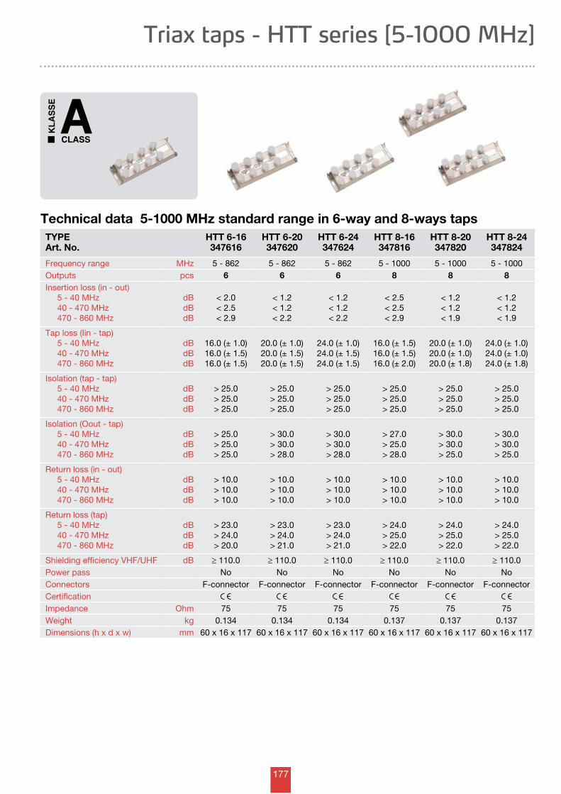
177
Technical data 5-1000 MHz standard range in 6-way and 8-ways tapsTYPEArt. No.
HTT 6-16347616
HTT 6-20347620
HTT 6-24347624
HTT 8-16347816
HTT 8-20347820
HTT 8-24347824
Frequency range MHz 5 - 862 5 - 862 5 - 862 5 - 1000 5 - 1000 5 - 1000Outputs pcs 6 6 6 8 8 8Insertion loss (in - out) 5 - 40 MHz 40 - 470 MHz 470 - 860 MHz
dBdBdB
< 2.0< 2.5< 2.9
< 1.2< 1.2< 2.2
< 1.2< 1.2< 2.2
< 2.5< 2.5< 2.9
< 1.2< 1.2< 1.9
< 1.2< 1.2< 1.9
Tap loss (Iin - tap) 5 - 40 MHz 40 - 470 MHz 470 - 860 MHz
dBdBdB
16.0 (± 1.0)16.0 (± 1.5)16.0 (± 1.5)
20.0 (± 1.0)20.0 (± 1.5)20.0 (± 1.5)
24.0 (± 1.0)24.0 (± 1.5)24.0 (± 1.5)
16.0 (± 1.5)16.0 (± 1.5)16.0 (± 2.0)
20.0 (± 1.0)20.0 (± 1.0)20.0 (± 1.8)
24.0 (± 1.0)24.0 (± 1.0)24.0 (± 1.8)
Isolation (tap - tap) 5 - 40 MHz 40 - 470 MHz 470 - 860 MHz
dBdBdB
> 25.0> 25.0> 25.0
> 25.0> 25.0> 25.0
> 25.0> 25.0> 25.0
> 25.0> 25.0> 25.0
> 25.0> 25.0> 25.0
> 25.0> 25.0> 25.0
Isolation (Oout - tap) 5 - 40 MHz 40 - 470 MHz 470 - 860 MHz
dBdBdB
> 25.0> 25.0> 25.0
> 30.0> 30.0> 28.0
> 30.0> 30.0> 28.0
> 27.0> 25.0> 28.0
> 30.0> 30.0> 25.0
> 30.0> 30.0> 25.0
Return loss (in - out) 5 - 40 MHz 40 - 470 MHz 470 - 860 MHz
dBdBdB
> 10.0> 10.0> 10.0
> 10.0> 10.0> 10.0
> 10.0> 10.0> 10.0
> 10.0> 10.0> 10.0
> 10.0> 10.0> 10.0
> 10.0> 10.0> 10.0
Return loss (tap) 5 - 40 MHz 40 - 470 MHz 470 - 860 MHz
dBdBdB
> 23.0> 24.0> 20.0
> 23.0> 24.0> 21.0
> 23.0> 24.0> 21.0
> 24.0> 25.0> 22.0
> 24.0> 25.0> 22.0
> 24.0> 25.0> 22.0
Shielding efficiency VHF/UHF dB ≥ 110.0 ≥ 110.0 ≥ 110.0 ≥ 110.0 ≥ 110.0 ≥ 110.0Power pass No No No No No NoConnectors F-connector F-connector F-connector F-connector F-connector F-connectorCertificationImpedance Ohm 75 75 75 75 75 75Weight kg 0.134 0.134 0.134 0.137 0.137 0.137Dimensions (h x d x w) mm 60 x 16 x 117 60 x 16 x 117 60 x 16 x 117 60 x 16 x 117 60 x 16 x 117 60 x 16 x 117
Triax taps - HTT series [5-1000 MHz]
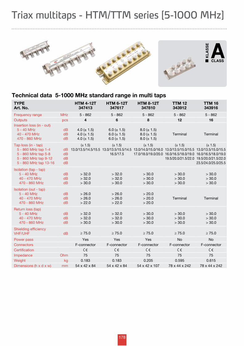
178
Technical data 5-1000 MHz standard range in multi tapsTYPEArt. No.
HTM 4-12T347413
HTM 6-12T347617
HTM 8-12T347810
TTM 12343912
TTM 16343916
Frequency range MHz 5 - 862 5 - 862 5 - 862 5 - 862 5 - 862Outputs pcs 4 6 8 12 16Insertion loss (in - out) 5 - 40 MHz 40 - 470 MHz 470 - 860 MHz
dBdBdB
4.0 (± 1.5)4.0 (± 1.5)4.0 (± 1.5)
6.0 (± 1.5)6.0 (± 1.5)6.0 (± 1.5)
8.0 (± 1.5)8.0 (± 1.5)8.0 (± 1.5)
Terminal Terminal
Tap loss (in - tap) 5 - 860 MHz tap 1-4 5 - 860 MHz tap 5-8 5 - 860 MHz tap 9-12 5 - 860 MHz tap 13-16
dBdBdBdB
(± 1.5)13.0/13.5/14.5/15.5
(± 1.5)13.0/13.5/15.5/14.5
16.5/17.5
(± 1.5)13.0/14.0/15.0/16.017.0/18.0/19.0/20.0
(± 1.5)13.0/13.5/15.0/15.516.0/16.5/18.0/19.019.5/20.0/21.5/22.0
(± 1.5)13.0/13.5/15.0/15.516.0/16.5/18.0/19.019.5/20.0/21.5/22.023.5/24.0/25.0/25.5
Isolation (tap - tap) 5 - 40 MHz 40 - 470 MHz 470 - 860 MHz
dBdBdB
> 32.0> 32.0> 30.0
> 32.0> 32.0> 30.0
> 30.0> 30.0> 30.0
> 30.0> 30.0> 30.0
> 30.0> 30.0> 30.0
Isolation (out - tap) 5 - 40 MHz 40 - 470 MHz 470 - 860 MHz
dBdBdB
> 26.0> 26.0> 22.0
> 26.0> 26.0> 22.0
> 20.0> 20.0> 20.0
Terminal Terminal
Return loss (tap) 5 - 40 MHz 40 - 470 MHz 470 - 860 MHz
dBdBdB
> 32.0> 32.0> 30.0
> 32.0> 32.0> 30.0
> 30.0> 30.0> 30.0
> 30.0> 30.0> 30.0
> 30.0> 30.0> 30.0
Shielding efficiency VHF/UHF dB ≥ 75.0 ≥ 75.0 ≥ 75.0 ≥ 75.0 ≥ 75.0
Power pass Yes Yes Yes No NoConnectors F-connector F-connector F-connector F-connector F-connectorCertificationImpedance Ohm 75 75 75 75 75Weight kg 0.183 0.183 0.205 0.595 0.615Dimensions (h x d x w) mm 54 x 42 x 84 54 x 42 x 84 54 x 42 x 107 78 x 44 x 242 78 x 44 x 242
Triax multitaps - HTM/TTM series [5-1000 MHz]
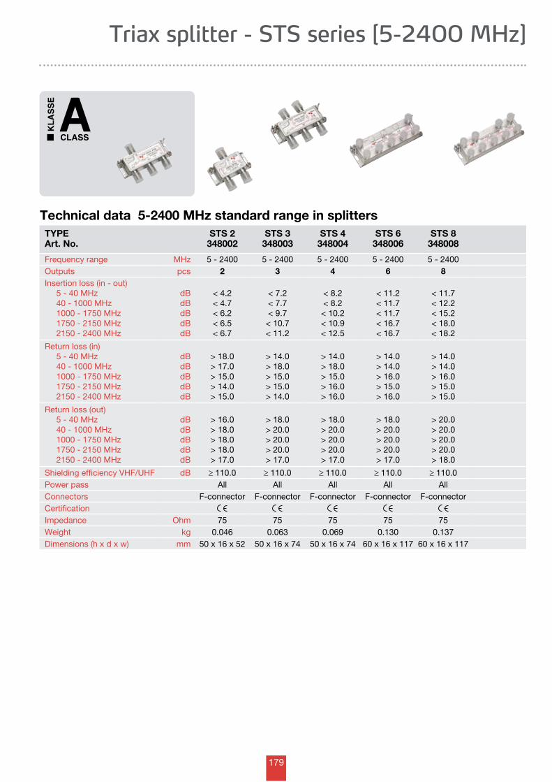
179
Triax splitter - STS series [5-2400 MHz]
Technical data 5-2400 MHz standard range in splittersTYPEArt. No.
STS 2348002
STS 3348003
STS 4348004
STS 6348006
STS 8348008
Frequency range MHz 5 - 2400 5 - 2400 5 - 2400 5 - 2400 5 - 2400Outputs pcs 2 3 4 6 8Insertion loss (in - out) 5 - 40 MHz 40 - 1000 MHz 1000 - 1750 MHz 1750 - 2150 MHz 2150 - 2400 MHz
dBdBdBdBdB
< 4.2< 4.7< 6.2< 6.5< 6.7
< 7.2< 7.7< 9.7
< 10.7< 11.2
< 8.2< 8.2
< 10.2< 10.9< 12.5
< 11.2< 11.7< 11.7< 16.7< 16.7
< 11.7< 12.2< 15.2< 18.0< 18.2
Return loss (in) 5 - 40 MHz 40 - 1000 MHz 1000 - 1750 MHz 1750 - 2150 MHz 2150 - 2400 MHz
dBdBdBdBdB
> 18.0> 17.0> 15.0> 14.0> 15.0
> 14.0> 18.0> 15.0> 15.0> 14.0
> 14.0> 18.0> 15.0> 16.0> 16.0
> 14.0> 14.0> 16.0> 15.0> 16.0
> 14.0> 14.0> 16.0> 15.0> 15.0
Return loss (out) 5 - 40 MHz 40 - 1000 MHz 1000 - 1750 MHz 1750 - 2150 MHz 2150 - 2400 MHz
dBdBdBdBdB
> 16.0> 18.0> 18.0> 18.0> 17.0
> 18.0> 20.0> 20.0> 20.0> 17.0
> 18.0> 20.0> 20.0> 20.0> 17.0
> 18.0> 20.0> 20.0> 20.0> 17.0
> 20.0> 20.0> 20.0> 20.0> 18.0
Shielding efficiency VHF/UHF dB ≥ 110.0 ≥ 110.0 ≥ 110.0 ≥ 110.0 ≥ 110.0Power pass All All All All AllConnectors F-connector F-connector F-connector F-connector F-connectorCertificationImpedance Ohm 75 75 75 75 75Weight kg 0.046 0.063 0.069 0.130 0.137Dimensions (h x d x w) mm 50 x 16 x 52 50 x 16 x 74 50 x 16 x 74 60 x 16 x 117 60 x 16 x 117
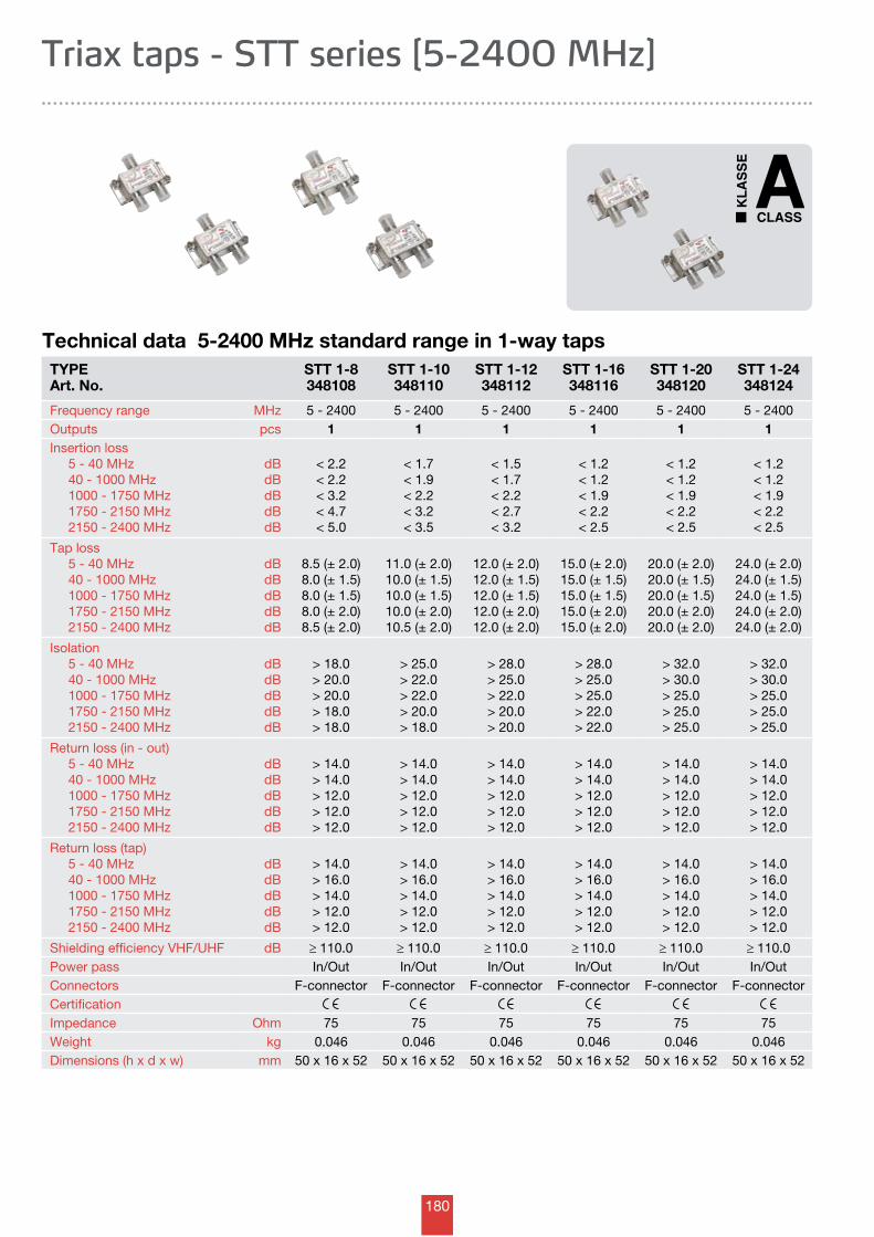
180
Technical data 5-2400 MHz standard range in 1-way tapsTYPEArt. No.
STT 1-8348108
STT 1-10348110
STT 1-12348112
STT 1-16348116
STT 1-20348120
STT 1-24348124
Frequency range MHz 5 - 2400 5 - 2400 5 - 2400 5 - 2400 5 - 2400 5 - 2400Outputs pcs 1 1 1 1 1 1Insertion loss 5 - 40 MHz 40 - 1000 MHz 1000 - 1750 MHz 1750 - 2150 MHz 2150 - 2400 MHz
dBdBdBdBdB
< 2.2< 2.2< 3.2< 4.7< 5.0
< 1.7< 1.9< 2.2< 3.2< 3.5
< 1.5< 1.7< 2.2< 2.7< 3.2
< 1.2< 1.2< 1.9< 2.2< 2.5
< 1.2< 1.2< 1.9< 2.2< 2.5
< 1.2< 1.2< 1.9< 2.2< 2.5
Tap loss 5 - 40 MHz 40 - 1000 MHz 1000 - 1750 MHz 1750 - 2150 MHz 2150 - 2400 MHz
dBdBdBdBdB
8.5 (± 2.0)8.0 (± 1.5)8.0 (± 1.5)8.0 (± 2.0)8.5 (± 2.0)
11.0 (± 2.0)10.0 (± 1.5)10.0 (± 1.5)10.0 (± 2.0)10.5 (± 2.0)
12.0 (± 2.0)12.0 (± 1.5)12.0 (± 1.5)12.0 (± 2.0)12.0 (± 2.0)
15.0 (± 2.0)15.0 (± 1.5)15.0 (± 1.5)15.0 (± 2.0)15.0 (± 2.0)
20.0 (± 2.0)20.0 (± 1.5)20.0 (± 1.5)20.0 (± 2.0)20.0 (± 2.0)
24.0 (± 2.0)24.0 (± 1.5)24.0 (± 1.5)24.0 (± 2.0)24.0 (± 2.0)
Isolation 5 - 40 MHz 40 - 1000 MHz 1000 - 1750 MHz 1750 - 2150 MHz 2150 - 2400 MHz
dBdBdBdBdB
> 18.0> 20.0> 20.0> 18.0> 18.0
> 25.0> 22.0> 22.0> 20.0> 18.0
> 28.0> 25.0> 22.0> 20.0> 20.0
> 28.0> 25.0> 25.0> 22.0> 22.0
> 32.0> 30.0> 25.0> 25.0> 25.0
> 32.0> 30.0> 25.0> 25.0> 25.0
Return loss (in - out) 5 - 40 MHz 40 - 1000 MHz 1000 - 1750 MHz 1750 - 2150 MHz 2150 - 2400 MHz
dBdBdBdBdB
> 14.0> 14.0> 12.0> 12.0> 12.0
> 14.0> 14.0> 12.0> 12.0> 12.0
> 14.0> 14.0> 12.0> 12.0> 12.0
> 14.0> 14.0> 12.0> 12.0> 12.0
> 14.0> 14.0> 12.0> 12.0> 12.0
> 14.0> 14.0> 12.0> 12.0> 12.0
Return loss (tap) 5 - 40 MHz 40 - 1000 MHz 1000 - 1750 MHz 1750 - 2150 MHz 2150 - 2400 MHz
dBdBdBdBdB
> 14.0> 16.0> 14.0> 12.0> 12.0
> 14.0> 16.0> 14.0> 12.0> 12.0
> 14.0> 16.0> 14.0> 12.0> 12.0
> 14.0> 16.0> 14.0> 12.0> 12.0
> 14.0> 16.0> 14.0> 12.0> 12.0
> 14.0> 16.0> 14.0> 12.0> 12.0
Shielding efficiency VHF/UHF dB ≥ 110.0 ≥ 110.0 ≥ 110.0 ≥ 110.0 ≥ 110.0 ≥ 110.0Power pass In/Out In/Out In/Out In/Out In/Out In/OutConnectors F-connector F-connector F-connector F-connector F-connector F-connectorCertificationImpedance Ohm 75 75 75 75 75 75Weight kg 0.046 0.046 0.046 0.046 0.046 0.046Dimensions (h x d x w) mm 50 x 16 x 52 50 x 16 x 52 50 x 16 x 52 50 x 16 x 52 50 x 16 x 52 50 x 16 x 52
Triax taps - STT series [5-2400 MHz]
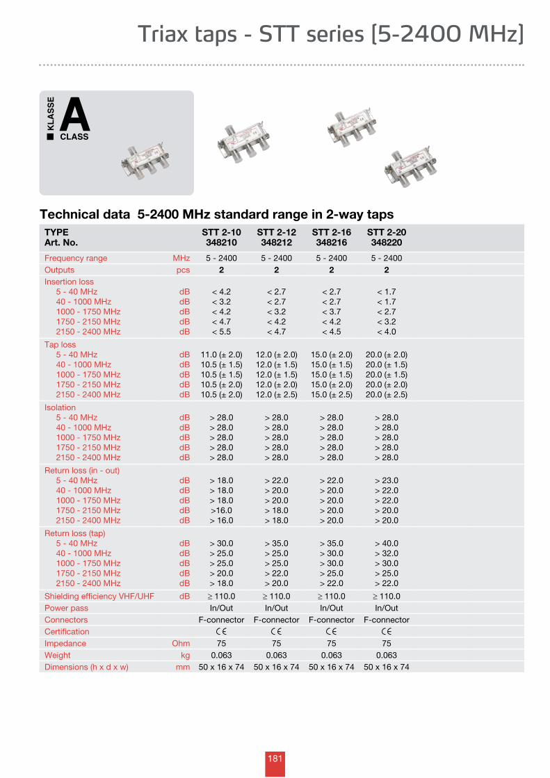
181
Technical data 5-2400 MHz standard range in 2-way tapsTYPEArt. No.
STT 2-10348210
STT 2-12348212
STT 2-16348216
STT 2-20348220
Frequency range MHz 5 - 2400 5 - 2400 5 - 2400 5 - 2400Outputs pcs 2 2 2 2Insertion loss 5 - 40 MHz 40 - 1000 MHz 1000 - 1750 MHz 1750 - 2150 MHz 2150 - 2400 MHz
dBdBdBdBdB
< 4.2< 3.2< 4.2< 4.7< 5.5
< 2.7< 2.7< 3.2< 4.2< 4.7
< 2.7< 2.7< 3.7< 4.2< 4.5
< 1.7< 1.7< 2.7< 3.2< 4.0
Tap loss 5 - 40 MHz 40 - 1000 MHz 1000 - 1750 MHz 1750 - 2150 MHz 2150 - 2400 MHz
dBdBdBdBdB
11.0 (± 2.0)10.5 (± 1.5)10.5 (± 1.5)10.5 (± 2.0)10.5 (± 2.0)
12.0 (± 2.0)12.0 (± 1.5)12.0 (± 1.5)12.0 (± 2.0)12.0 (± 2.5)
15.0 (± 2.0)15.0 (± 1.5)15.0 (± 1.5)15.0 (± 2.0)15.0 (± 2.5)
20.0 (± 2.0)20.0 (± 1.5)20.0 (± 1.5)20.0 (± 2.0)20.0 (± 2.5)
Isolation 5 - 40 MHz 40 - 1000 MHz 1000 - 1750 MHz 1750 - 2150 MHz 2150 - 2400 MHz
dBdBdBdBdB
> 28.0> 28.0> 28.0> 28.0> 28.0
> 28.0> 28.0> 28.0> 28.0> 28.0
> 28.0> 28.0> 28.0> 28.0> 28.0
> 28.0> 28.0> 28.0> 28.0> 28.0
Return loss (in - out) 5 - 40 MHz 40 - 1000 MHz 1000 - 1750 MHz 1750 - 2150 MHz 2150 - 2400 MHz
dBdBdBdBdB
> 18.0> 18.0> 18.0>16.0> 16.0
> 22.0> 20.0> 20.0> 18.0> 18.0
> 22.0> 20.0> 20.0> 20.0> 20.0
> 23.0> 22.0> 22.0> 20.0> 20.0
Return loss (tap) 5 - 40 MHz 40 - 1000 MHz 1000 - 1750 MHz 1750 - 2150 MHz 2150 - 2400 MHz
dBdBdBdBdB
> 30.0> 25.0> 25.0> 20.0> 18.0
> 35.0> 25.0> 25.0> 22.0> 20.0
> 35.0> 30.0> 30.0> 25.0> 22.0
> 40.0> 32.0> 30.0> 25.0> 22.0
Shielding efficiency VHF/UHF dB ≥ 110.0 ≥ 110.0 ≥ 110.0 ≥ 110.0Power pass In/Out In/Out In/Out In/OutConnectors F-connector F-connector F-connector F-connectorCertificationImpedance Ohm 75 75 75 75Weight kg 0.063 0.063 0.063 0.063Dimensions (h x d x w) mm 50 x 16 x 74 50 x 16 x 74 50 x 16 x 74 50 x 16 x 74
Triax taps - STT series [5-2400 MHz]
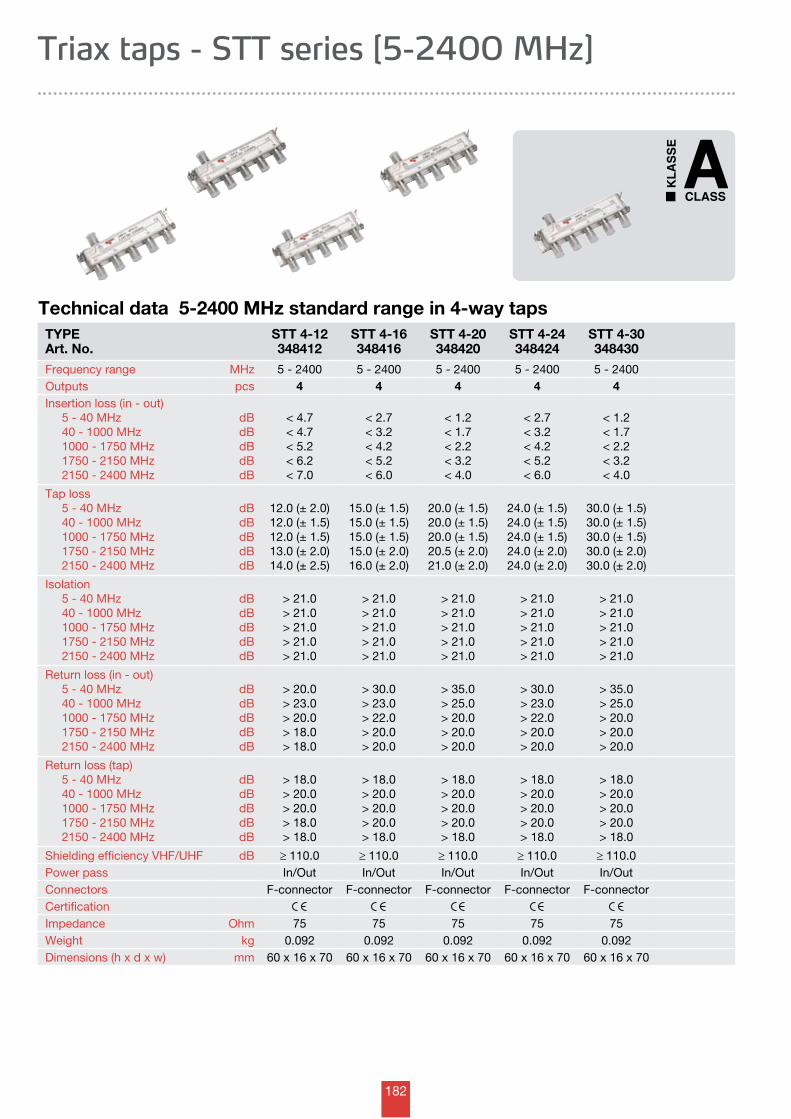
182
Technical data 5-2400 MHz standard range in 4-way tapsTYPEArt. No.
STT 4-12348412
STT 4-16348416
STT 4-20348420
STT 4-24348424
STT 4-30348430
Frequency range MHz 5 - 2400 5 - 2400 5 - 2400 5 - 2400 5 - 2400Outputs pcs 4 4 4 4 4Insertion loss (in - out) 5 - 40 MHz 40 - 1000 MHz 1000 - 1750 MHz 1750 - 2150 MHz 2150 - 2400 MHz
dBdBdBdBdB
< 4.7< 4.7< 5.2< 6.2< 7.0
< 2.7< 3.2< 4.2< 5.2< 6.0
< 1.2< 1.7< 2.2< 3.2< 4.0
< 2.7< 3.2< 4.2< 5.2< 6.0
< 1.2< 1.7< 2.2< 3.2< 4.0
Tap loss 5 - 40 MHz 40 - 1000 MHz 1000 - 1750 MHz 1750 - 2150 MHz 2150 - 2400 MHz
dBdBdBdBdB
12.0 (± 2.0)12.0 (± 1.5)12.0 (± 1.5)13.0 (± 2.0)14.0 (± 2.5)
15.0 (± 1.5)15.0 (± 1.5)15.0 (± 1.5)15.0 (± 2.0)16.0 (± 2.0)
20.0 (± 1.5)20.0 (± 1.5)20.0 (± 1.5)20.5 (± 2.0)21.0 (± 2.0)
24.0 (± 1.5)24.0 (± 1.5)24.0 (± 1.5)24.0 (± 2.0)24.0 (± 2.0)
30.0 (± 1.5)30.0 (± 1.5)30.0 (± 1.5)30.0 (± 2.0)30.0 (± 2.0)
Isolation 5 - 40 MHz 40 - 1000 MHz 1000 - 1750 MHz 1750 - 2150 MHz 2150 - 2400 MHz
dBdBdBdBdB
> 21.0> 21.0> 21.0> 21.0> 21.0
> 21.0> 21.0> 21.0> 21.0> 21.0
> 21.0> 21.0> 21.0> 21.0> 21.0
> 21.0> 21.0> 21.0> 21.0> 21.0
> 21.0> 21.0> 21.0> 21.0> 21.0
Return loss (in - out) 5 - 40 MHz 40 - 1000 MHz 1000 - 1750 MHz 1750 - 2150 MHz 2150 - 2400 MHz
dBdBdBdBdB
> 20.0> 23.0> 20.0> 18.0> 18.0
> 30.0> 23.0> 22.0> 20.0> 20.0
> 35.0> 25.0> 20.0> 20.0> 20.0
> 30.0> 23.0> 22.0> 20.0> 20.0
> 35.0> 25.0> 20.0> 20.0> 20.0
Return loss (tap) 5 - 40 MHz 40 - 1000 MHz 1000 - 1750 MHz 1750 - 2150 MHz 2150 - 2400 MHz
dBdBdBdBdB
> 18.0> 20.0> 20.0> 18.0> 18.0
> 18.0> 20.0> 20.0> 20.0> 18.0
> 18.0> 20.0> 20.0> 20.0> 18.0
> 18.0> 20.0> 20.0> 20.0> 18.0
> 18.0> 20.0> 20.0> 20.0> 18.0
Shielding efficiency VHF/UHF dB ≥ 110.0 ≥ 110.0 ≥ 110.0 ≥ 110.0 ≥ 110.0Power pass In/Out In/Out In/Out In/Out In/OutConnectors F-connector F-connector F-connector F-connector F-connectorCertificationImpedance Ohm 75 75 75 75 75Weight kg 0.092 0.092 0.092 0.092 0.092Dimensions (h x d x w) mm 60 x 16 x 70 60 x 16 x 70 60 x 16 x 70 60 x 16 x 70 60 x 16 x 70
Triax taps - STT series [5-2400 MHz]
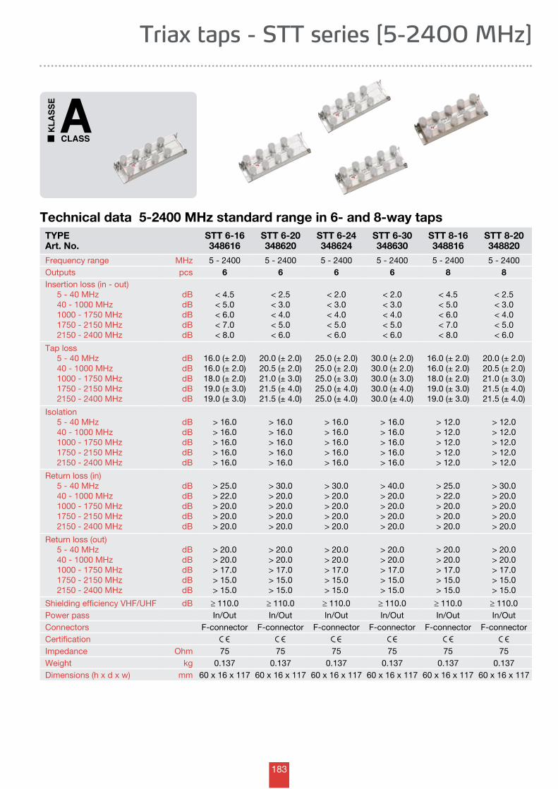
183
Technical data 5-2400 MHz standard range in 6- and 8-way tapsTYPEArt. No.
STT 6-16348616
STT 6-20348620
STT 6-24348624
STT 6-30348630
STT 8-16348816
STT 8-20348820
Frequency range MHz 5 - 2400 5 - 2400 5 - 2400 5 - 2400 5 - 2400 5 - 2400Outputs pcs 6 6 6 6 8 8Insertion loss (in - out) 5 - 40 MHz 40 - 1000 MHz 1000 - 1750 MHz 1750 - 2150 MHz 2150 - 2400 MHz
dBdBdBdBdB
< 4.5< 5.0< 6.0< 7.0< 8.0
< 2.5< 3.0< 4.0< 5.0< 6.0
< 2.0< 3.0< 4.0< 5.0< 6.0
< 2.0< 3.0< 4.0< 5.0< 6.0
< 4.5< 5.0< 6.0< 7.0< 8.0
< 2.5< 3.0< 4.0< 5.0< 6.0
Tap loss 5 - 40 MHz 40 - 1000 MHz 1000 - 1750 MHz 1750 - 2150 MHz 2150 - 2400 MHz
dBdBdBdBdB
16.0 (± 2.0)16.0 (± 2.0)18.0 (± 2.0)19.0 (± 3.0)19.0 (± 3.0)
20.0 (± 2.0)20.5 (± 2.0)21.0 (± 3.0)21.5 (± 4.0)21.5 (± 4.0)
25.0 (± 2.0)25.0 (± 2.0)25.0 (± 3.0)25.0 (± 4.0)25.0 (± 4.0)
30.0 (± 2.0)30.0 (± 2.0)30.0 (± 3.0)30.0 (± 4.0)30.0 (± 4.0)
16.0 (± 2.0)16.0 (± 2.0)18.0 (± 2.0)19.0 (± 3.0)19.0 (± 3.0)
20.0 (± 2.0)20.5 (± 2.0)21.0 (± 3.0)21.5 (± 4.0)21.5 (± 4.0)
Isolation 5 - 40 MHz 40 - 1000 MHz 1000 - 1750 MHz 1750 - 2150 MHz 2150 - 2400 MHz
dBdBdBdBdB
> 16.0> 16.0> 16.0> 16.0> 16.0
> 16.0> 16.0> 16.0> 16.0> 16.0
> 16.0> 16.0> 16.0> 16.0> 16.0
> 16.0> 16.0> 16.0> 16.0> 16.0
> 12.0> 12.0> 12.0> 12.0> 12.0
> 12.0> 12.0> 12.0> 12.0> 12.0
Return loss (in) 5 - 40 MHz 40 - 1000 MHz 1000 - 1750 MHz 1750 - 2150 MHz 2150 - 2400 MHz
dBdBdBdBdB
> 25.0> 22.0> 20.0> 20.0> 20.0
> 30.0> 20.0> 20.0> 20.0> 20.0
> 30.0> 20.0> 20.0> 20.0> 20.0
> 40.0> 20.0> 20.0> 20.0> 20.0
> 25.0> 22.0> 20.0> 20.0> 20.0
> 30.0> 20.0> 20.0> 20.0> 20.0
Return loss (out) 5 - 40 MHz 40 - 1000 MHz 1000 - 1750 MHz 1750 - 2150 MHz 2150 - 2400 MHz
dBdBdBdBdB
> 20.0> 20.0> 17.0> 15.0> 15.0
> 20.0> 20.0> 17.0> 15.0> 15.0
> 20.0> 20.0> 17.0> 15.0> 15.0
> 20.0> 20.0> 17.0> 15.0> 15.0
> 20.0> 20.0> 17.0> 15.0> 15.0
> 20.0> 20.0> 17.0> 15.0> 15.0
Shielding efficiency VHF/UHF dB ≥ 110.0 ≥ 110.0 ≥ 110.0 ≥ 110.0 ≥ 110.0 ≥ 110.0Power pass In/Out In/Out In/Out In/Out In/Out In/OutConnectors F-connector F-connector F-connector F-connector F-connector F-connectorCertificationImpedance Ohm 75 75 75 75 75 75Weight kg 0.137 0.137 0.137 0.137 0.137 0.137Dimensions (h x d x w) mm 60 x 16 x 117 60 x 16 x 117 60 x 16 x 117 60 x 16 x 117 60 x 16 x 117 60 x 16 x 117
Triax taps - STT series [5-2400 MHz]
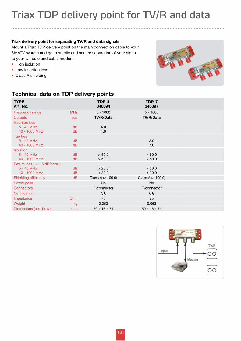
184
Technical data on TDP delivery pointsTYPEArt. No.
TDP-4346094
TDP-7346097
Frequency range MHz 5 - 1000 5 - 1000Outputs pcs TV/R/Data TV/R/DataInsertion loss 5 - 40 MHz 40 - 1000 MHz
dBdB
4.04.0
Tap loss 5 - 40 MHz 40 - 1000 MHz
dBdB
2.07.0
Isolation 5 - 40 MHz 40 - 1000 MHz
dBdB
> 50.0> 50.0
> 50.0> 50.0
Return loss (-1.5 dB/octav) 5 - 40 MHz 40 - 1000 MHz
dBdB
> 20.0> 20.0
> 20.0> 20.0
Shielding efficiency dB Class A (≥ 100.0) Class A (≥ 100.0)Power pass No NoConnectors F-connector F-connectorCertificationImpedance Ohm 75 75Weight kg 0.063 0.063Dimensions (h x d x w) mm 50 x 16 x 74 50 x 16 x 74
Triax TDP delivery point for TV/R and data
Triax delivery point for separating TV/R and data signals Mount a Triax TDP delivery point on the main connection cable to your SMATV system and get a stabile and secure separation of your signal to your tv, radio and cable modem.• High isolation• Low insertion loss• Class A shielding
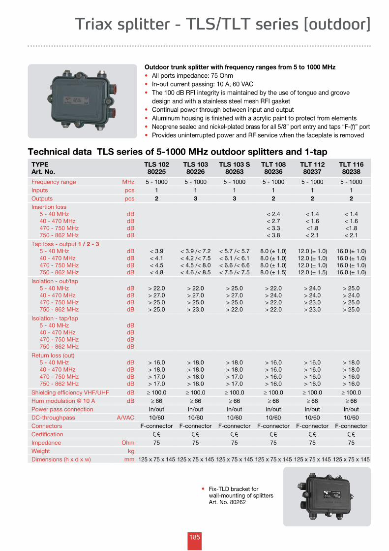
185
Technical data TLS series of 5-1000 MHz outdoor splitters and 1-tapTYPEArt. No.
TLS 10280225
TLS 10380226
TLS 103 S 80263
TLT 108 80236
TLT 112 80237
TLT 116 80238
Frequency range MHz 5 - 1000 5 - 1000 5 - 1000 5 - 1000 5 - 1000 5 - 1000Inputs pcs 1 1 1 1 1 1Outputs pcs 2 3 3 2 2 2Insertion loss 5 - 40 MHz 40 - 470 MHz 470 - 750 MHz 750 - 862 MHz
dBdBdBdB
< 2.4< 2.7< 3.3< 3.8
< 1.4< 1.6<1.8< 2.1
< 1.4< 1.6<1.8< 2.1
Tap loss - output 1 / 2 - 3 5 - 40 MHz 40 - 470 MHz 470 - 750 MHz 750 - 862 MHz
dBdBdBdB
< 3.9< 4.1< 4.5< 4.8
< 3.9 /< 7.2< 4.2 /< 7.5< 4.5 /< 8.0< 4.6 /< 8.5
< 5.7 /< 5.7< 6.1 /< 6.1< 6.6 /< 6.6< 7.5 /< 7.5
8.0 (± 1.0) 8.0 (± 1.0) 8.0 (± 1.0) 8.0 (± 1.5)
12.0 (± 1.0) 12.0 (± 1.0) 12.0 (± 1.0) 12.0 (± 1.5)
16.0 (± 1.0) 16.0 (± 1.0) 16.0 (± 1.0) 16.0 (± 1.0)
Isolation - out/tap 5 - 40 MHz 40 - 470 MHz 470 - 750 MHz 750 - 862 MHz
dBdBdBdB
> 22.0> 27.0> 25.0> 25.0
> 22.0> 27.0> 25.0> 23.0
> 25.0> 27.0> 25.0> 22.0
> 22.0> 24.0> 22.0> 22.0
> 24.0> 24.0> 23.0> 23.0
> 25.0> 24.0> 25.0> 25.0
Isolation - tap/tap 5 - 40 MHz 40 - 470 MHz 470 - 750 MHz 750 - 862 MHz
dBdBdBdB
Return loss (out) 5 - 40 MHz 40 - 470 MHz 470 - 750 MHz 750 - 862 MHz
dBdBdBdB
> 16.0> 18.0> 17.0> 17.0
> 18.0> 18.0> 18.0> 18.0
> 18.0> 18.0> 17.0> 17.0
> 16.0> 16.0> 16.0> 16.0
> 16.0> 16.0> 16.0> 16.0
> 18.0> 18.0> 16.0> 16.0
Shielding efficiency VHF/UHF dB ≥ 100.0 ≥ 100.0 ≥ 100.0 ≥ 100.0 ≥ 100.0 ≥ 100.0Hum modulation @ 10 A dB ≥ 66 ≥ 66 ≥ 66 ≥ 66 ≥ 66 ≥ 66Power pass connection In/out In/out In/out In/out In/out In/outDC-throughpass A/VAC 10/60 10/60 10/60 10/60 10/60 10/60 Connectors F-connector F-connector F-connector F-connector F-connector F-connectorCertificationImpedance Ohm 75 75 75 75 75 75Weight kgDimensions (h x d x w) mm 125 x 75 x 145 125 x 75 x 145 125 x 75 x 145 125 x 75 x 145 125 x 75 x 145 125 x 75 x 145
Triax splitter - TLS/TLT series [outdoor]
Outdoor trunk splitter with frequency ranges from 5 to 1000 MHz • All ports impedance: 75 Ohm • In-out current passing: 10 A, 60 VAC • The 100 dB RFI integrity is maintained by the use of tongue and groove design and with a stainless steel mesh RFI gasket• Continual power through between input and output • Aluminum housing is finished with a acrylic paint to protect from elements • Neoprene sealed and nickel-plated brass for all 5/8” port entry and taps “F-(f)” port •Provides uninterrupted power and RF service when the faceplate is removed
• Fix-TLD bracket for wall-mounting of splitters Art. No. 80262
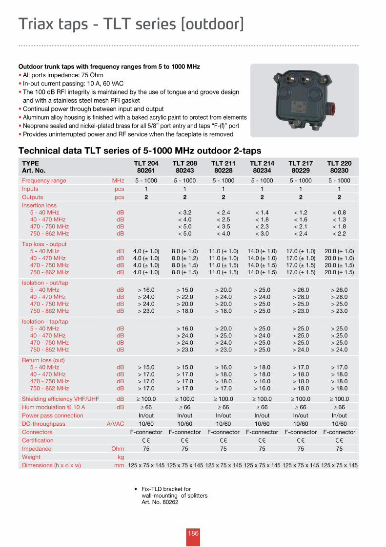
186
Technical data TLT series of 5-1000 MHz outdoor 2-taps
Outdoor trunk taps with frequency ranges from 5 to 1000 MHz • All ports impedance: 75 Ohm • In-out current passing: 10 A, 60 VAC • The 100 dB RFI integrity is maintained by the use of tongue and groove design and with a stainless steel mesh RFI gasket• Continual power through between input and output • Aluminum alloy housing is finished with a baked acrylic paint to protect from elements • Neoprene sealed and nickel-plated brass for all 5/8” port entry and taps “F-(f)” port • Provides uninterrupted power and RF service when the faceplate is removed
Triax taps - TLT series [outdoor]
TYPEArt. No.
TLT 204 80261
TLT 20880243
TLT 21180228
TLT 21480234
TLT 21780229
TLT 22080230
Frequency range MHz 5 - 1000 5 - 1000 5 - 1000 5 - 1000 5 - 1000 5 - 1000Inputs pcs 1 1 1 1 1 1Outputs pcs 2 2 2 2 2 2Insertion loss 5 - 40 MHz 40 - 470 MHz 470 - 750 MHz 750 - 862 MHz
dBdBdBdB
< 3.2< 4.0< 5.0< 5.0
< 2.4< 2.5< 3.5< 4.0
< 1.4< 1.8< 2.3< 3.0
< 1.2< 1.6< 2.1< 2.4
< 0.8< 1.3< 1.8< 2.2
Tap loss - output 5 - 40 MHz 40 - 470 MHz 470 - 750 MHz 750 - 862 MHz
dBdBdBdB
4.0 (± 1.0) 4.0 (± 1.0) 4.0 (± 1.0) 4.0 (± 1.0)
8.0 (± 1.0) 8.0 (± 1.2) 8.0 (± 1.5) 8.0 (± 1.5)
11.0 (± 1.0) 11.0 (± 1.0) 11.0 (± 1.5) 11.0 (± 1.5)
14.0 (± 1.0) 14.0 (± 1.0) 14.0 (± 1.5) 14.0 (± 1.5)
17.0 (± 1.0) 17.0 (± 1.0) 17.0 (± 1.5) 17.0 (± 1.5)
20.0 (± 1.0) 20.0 (± 1.0) 20.0 (± 1.5) 20.0 (± 1.5)
Isolation - out/tap 5 - 40 MHz 40 - 470 MHz 470 - 750 MHz 750 - 862 MHz
dBdBdBdB
> 16.0> 24.0> 24.0> 23.0
> 15.0> 22.0> 20.0> 18.0
> 20.0> 24.0> 20.0> 18.0
> 25.0> 24.0> 25.0> 25.0
> 26.0> 28.0> 25.0> 23.0
> 26.0> 28.0> 25.0> 23.0
Isolation - tap/tap 5 - 40 MHz 40 - 470 MHz 470 - 750 MHz 750 - 862 MHz
dBdBdBdB
> 16.0> 24.0> 24.0> 23.0
> 20.0> 25.0> 24.0> 23.0
> 25.0> 24.0> 25.0> 25.0
> 25.0> 25.0> 25.0> 24.0
> 25.0> 25.0> 25.0> 24.0
Return loss (out) 5 - 40 MHz 40 - 470 MHz 470 - 750 MHz 750 - 862 MHz
dBdBdBdB
> 15.0> 17.0> 17.0> 17.0
> 15.0> 17.0> 17.0> 17.0
> 16.0> 18.0> 18.0> 17.0
> 18.0> 18.0> 16.0> 16.0
> 17.0> 18.0> 18.0> 18.0
> 17.0> 18.0> 18.0> 18.0
Shielding efficiency VHF/UHF dB ≥ 100.0 ≥ 100.0 ≥ 100.0 ≥ 100.0 ≥ 100.0 ≥ 100.0Hum modulation @ 10 A dB ≥ 66 ≥ 66 ≥ 66 ≥ 66 ≥ 66 ≥ 66Power pass connection In/out In/out In/out In/out In/out In/outDC-throughpass A/VAC 10/60 10/60 10/60 10/60 10/60 10/60 Connectors F-connector F-connector F-connector F-connector F-connector F-connectorCertificationImpedance Ohm 75 75 75 75 75 75Weight kgDimensions (h x d x w) mm 125 x 75 x 145 125 x 75 x 145 125 x 75 x 145 125 x 75 x 145 125 x 75 x 145 125 x 75 x 145
• Fix-TLDbracketfor wall-mounting of splitters Art. No. 80262
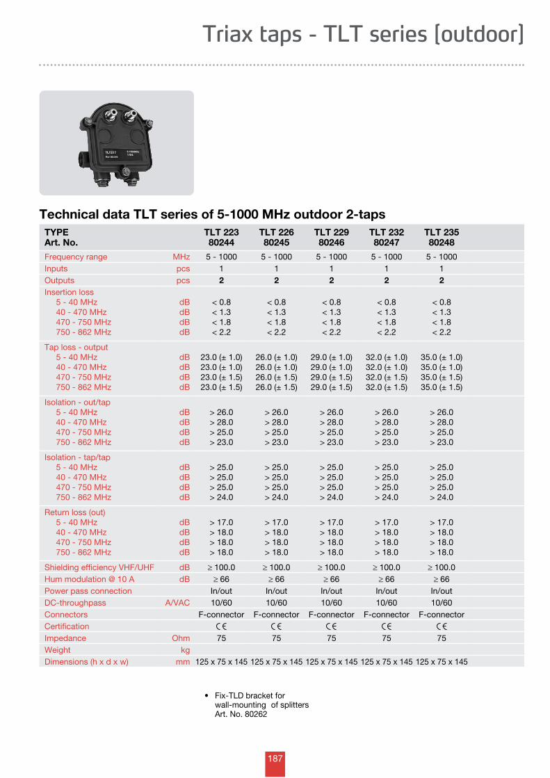
187
Triax taps - TLT series [outdoor]
Technical data TLT series of 5-1000 MHz outdoor 2-tapsTYPEArt. No.
TLT 22380244
TLT 22680245
TLT 22980246
TLT 23280247
TLT 23580248
Frequency range MHz 5 - 1000 5 - 1000 5 - 1000 5 - 1000 5 - 1000Inputs pcs 1 1 1 1 1Outputs pcs 2 2 2 2 2Insertion loss 5 - 40 MHz 40 - 470 MHz 470 - 750 MHz 750 - 862 MHz
dBdBdBdB
< 0.8< 1.3< 1.8< 2.2
< 0.8< 1.3< 1.8< 2.2
< 0.8< 1.3< 1.8< 2.2
< 0.8< 1.3< 1.8< 2.2
< 0.8< 1.3< 1.8< 2.2
Tap loss - output 5 - 40 MHz 40 - 470 MHz 470 - 750 MHz 750 - 862 MHz
dBdBdBdB
23.0 (± 1.0) 23.0 (± 1.0) 23.0 (± 1.5) 23.0 (± 1.5)
26.0 (± 1.0) 26.0 (± 1.0) 26.0 (± 1.5) 26.0 (± 1.5)
29.0 (± 1.0) 29.0 (± 1.0) 29.0 (± 1.5) 29.0 (± 1.5)
32.0 (± 1.0) 32.0 (± 1.0) 32.0 (± 1.5) 32.0 (± 1.5)
35.0 (± 1.0) 35.0 (± 1.0) 35.0 (± 1.5) 35.0 (± 1.5)
Isolation - out/tap 5 - 40 MHz 40 - 470 MHz 470 - 750 MHz 750 - 862 MHz
dBdBdBdB
> 26.0> 28.0> 25.0> 23.0
> 26.0> 28.0> 25.0> 23.0
> 26.0> 28.0> 25.0> 23.0
> 26.0> 28.0> 25.0> 23.0
> 26.0> 28.0> 25.0> 23.0
Isolation - tap/tap 5 - 40 MHz 40 - 470 MHz 470 - 750 MHz 750 - 862 MHz
dBdBdBdB
> 25.0> 25.0> 25.0> 24.0
> 25.0> 25.0> 25.0> 24.0
> 25.0> 25.0> 25.0> 24.0
> 25.0> 25.0> 25.0> 24.0
> 25.0> 25.0> 25.0> 24.0
Return loss (out) 5 - 40 MHz 40 - 470 MHz 470 - 750 MHz 750 - 862 MHz
dBdBdBdB
> 17.0> 18.0> 18.0> 18.0
> 17.0> 18.0> 18.0> 18.0
> 17.0> 18.0> 18.0> 18.0
> 17.0> 18.0> 18.0> 18.0
> 17.0> 18.0> 18.0> 18.0
Shielding efficiency VHF/UHF dB ≥ 100.0 ≥ 100.0 ≥ 100.0 ≥ 100.0 ≥ 100.0Hum modulation @ 10 A dB ≥ 66 ≥ 66 ≥ 66 ≥ 66 ≥ 66Power pass connection In/out In/out In/out In/out In/outDC-throughpass A/VAC 10/60 10/60 10/60 10/60 10/60 Connectors F-connector F-connector F-connector F-connector F-connectorCertificationImpedance Ohm 75 75 75 75 75Weight kgDimensions (h x d x w) mm 125 x 75 x 145 125 x 75 x 145 125 x 75 x 145 125 x 75 x 145 125 x 75 x 145
• Fix-TLDbracketfor wall-mounting of splitters Art. No. 80262
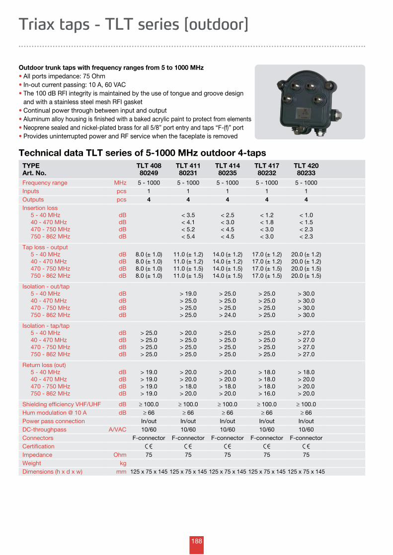
188
Technical data TLT series of 5-1000 MHz outdoor 4-taps
Triax taps - TLT series [outdoor]
TYPEArt. No.
TLT 408 80249
TLT 41180231
TLT 41480235
TLT 41780232
TLT 42080233
Frequency range MHz 5 - 1000 5 - 1000 5 - 1000 5 - 1000 5 - 1000Inputs pcs 1 1 1 1 1Outputs pcs 4 4 4 4 4Insertion loss 5 - 40 MHz 40 - 470 MHz 470 - 750 MHz 750 - 862 MHz
dBdBdBdB
< 3.5< 4.1< 5.2< 5.4
< 2.5< 3.0< 4.5< 4.5
< 1.2< 1.8< 3.0< 3.0
< 1.0< 1.5< 2.3< 2.3
Tap loss - output 5 - 40 MHz 40 - 470 MHz 470 - 750 MHz 750 - 862 MHz
dBdBdBdB
8.0 (± 1.0) 8.0 (± 1.0) 8.0 (± 1.0) 8.0 (± 1.0)
11.0 (± 1.2) 11.0 (± 1.2) 11.0 (± 1.5) 11.0 (± 1.5)
14.0 (± 1.2) 14.0 (± 1.2) 14.0 (± 1.5) 14.0 (± 1.5)
17.0 (± 1.2) 17.0 (± 1.2) 17.0 (± 1.5) 17.0 (± 1.5)
20.0 (± 1.2) 20.0 (± 1.2) 20.0 (± 1.5) 20.0 (± 1.5)
Isolation - out/tap 5 - 40 MHz 40 - 470 MHz 470 - 750 MHz 750 - 862 MHz
dBdBdBdB
> 19.0> 25.0> 25.0> 25.0
> 25.0> 25.0> 25.0> 24.0
> 25.0> 25.0> 25.0> 25.0
> 30.0> 30.0> 30.0> 30.0
Isolation - tap/tap 5 - 40 MHz 40 - 470 MHz 470 - 750 MHz 750 - 862 MHz
dBdBdBdB
> 25.0> 25.0> 25.0> 25.0
> 20.0> 25.0> 25.0> 25.0
> 25.0> 25.0> 25.0> 25.0
> 25.0> 25.0> 25.0> 25.0
> 27.0> 27.0> 27.0> 27.0
Return loss (out) 5 - 40 MHz 40 - 470 MHz 470 - 750 MHz 750 - 862 MHz
dBdBdBdB
> 19.0> 19.0> 19.0> 19.0
> 20.0> 20.0> 18.0> 20.0
> 20.0> 20.0> 18.0> 20.0
> 18.0> 18.0> 18.0> 16.0
> 18.0> 20.0> 20.0> 20.0
Shielding efficiency VHF/UHF dB ≥ 100.0 ≥ 100.0 ≥ 100.0 ≥ 100.0 ≥ 100.0Hum modulation @ 10 A dB ≥ 66 ≥ 66 ≥ 66 ≥ 66 ≥ 66Power pass connection In/out In/out In/out In/out In/outDC-throughpass A/VAC 10/60 10/60 10/60 10/60 10/60 Connectors F-connector F-connector F-connector F-connector F-connectorCertificationImpedance Ohm 75 75 75 75 75Weight kgDimensions (h x d x w) mm 125 x 75 x 145 125 x 75 x 145 125 x 75 x 145 125 x 75 x 145 125 x 75 x 145
Outdoor trunk taps with frequency ranges from 5 to 1000 MHz • All ports impedance: 75 Ohm • In-out current passing: 10 A, 60 VAC • The 100 dB RFI integrity is maintained by the use of tongue and groove design and with a stainless steel mesh RFI gasket• Continual power through between input and output • Aluminum alloy housing is finished with a baked acrylic paint to protect from elements • Neoprene sealed and nickel-plated brass for all 5/8” port entry and taps “F-(f)” port • Provides uninterrupted power and RF service when the faceplate is removed
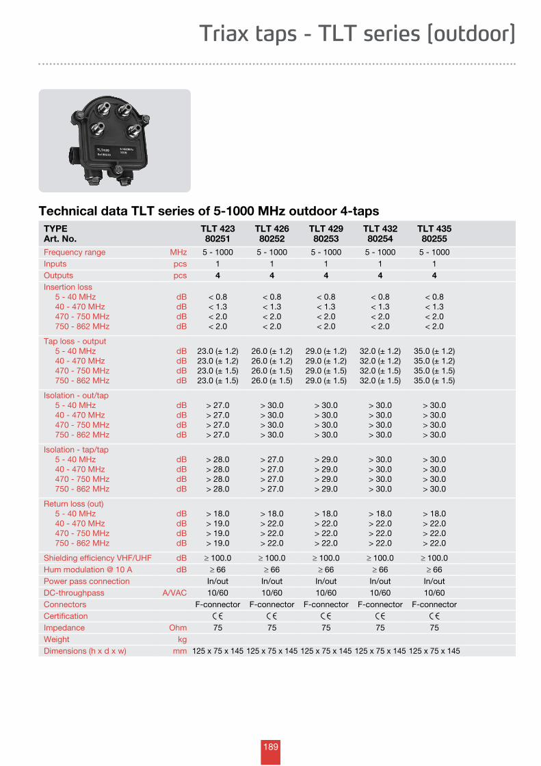
189
Triax taps - TLT series [outdoor]
Technical data TLT series of 5-1000 MHz outdoor 4-tapsTYPEArt. No.
TLT 42380251
TLT 42680252
TLT 42980253
TLT 43280254
TLT 43580255
Frequency range MHz 5 - 1000 5 - 1000 5 - 1000 5 - 1000 5 - 1000Inputs pcs 1 1 1 1 1Outputs pcs 4 4 4 4 4Insertion loss 5 - 40 MHz 40 - 470 MHz 470 - 750 MHz 750 - 862 MHz
dBdBdBdB
< 0.8< 1.3< 2.0< 2.0
< 0.8< 1.3< 2.0< 2.0
< 0.8< 1.3< 2.0< 2.0
< 0.8< 1.3< 2.0< 2.0
< 0.8< 1.3< 2.0< 2.0
Tap loss - output 5 - 40 MHz 40 - 470 MHz 470 - 750 MHz 750 - 862 MHz
dBdBdBdB
23.0 (± 1.2) 23.0 (± 1.2) 23.0 (± 1.5) 23.0 (± 1.5)
26.0 (± 1.2) 26.0 (± 1.2) 26.0 (± 1.5) 26.0 (± 1.5)
29.0 (± 1.2) 29.0 (± 1.2) 29.0 (± 1.5) 29.0 (± 1.5)
32.0 (± 1.2) 32.0 (± 1.2) 32.0 (± 1.5) 32.0 (± 1.5)
35.0 (± 1.2) 35.0 (± 1.2) 35.0 (± 1.5) 35.0 (± 1.5)
Isolation - out/tap 5 - 40 MHz 40 - 470 MHz 470 - 750 MHz 750 - 862 MHz
dBdBdBdB
> 27.0> 27.0> 27.0> 27.0
> 30.0> 30.0> 30.0> 30.0
> 30.0> 30.0> 30.0> 30.0
> 30.0> 30.0> 30.0> 30.0
> 30.0> 30.0> 30.0> 30.0
Isolation - tap/tap 5 - 40 MHz 40 - 470 MHz 470 - 750 MHz 750 - 862 MHz
dBdBdBdB
> 28.0> 28.0> 28.0> 28.0
> 27.0> 27.0> 27.0> 27.0
> 29.0> 29.0> 29.0> 29.0
> 30.0> 30.0> 30.0> 30.0
> 30.0> 30.0> 30.0> 30.0
Return loss (out) 5 - 40 MHz 40 - 470 MHz 470 - 750 MHz 750 - 862 MHz
dBdBdBdB
> 18.0> 19.0> 19.0> 19.0
> 18.0> 22.0> 22.0> 22.0
> 18.0> 22.0> 22.0> 22.0
> 18.0> 22.0> 22.0> 22.0
> 18.0> 22.0> 22.0> 22.0
Shielding efficiency VHF/UHF dB ≥ 100.0 ≥ 100.0 ≥ 100.0 ≥ 100.0 ≥ 100.0Hum modulation @ 10 A dB ≥ 66 ≥ 66 ≥ 66 ≥ 66 ≥ 66Power pass connection In/out In/out In/out In/out In/outDC-throughpass A/VAC 10/60 10/60 10/60 10/60 10/60 Connectors F-connector F-connector F-connector F-connector F-connectorCertificationImpedance Ohm 75 75 75 75 75Weight kgDimensions (h x d x w) mm 125 x 75 x 145 125 x 75 x 145 125 x 75 x 145 125 x 75 x 145 125 x 75 x 145
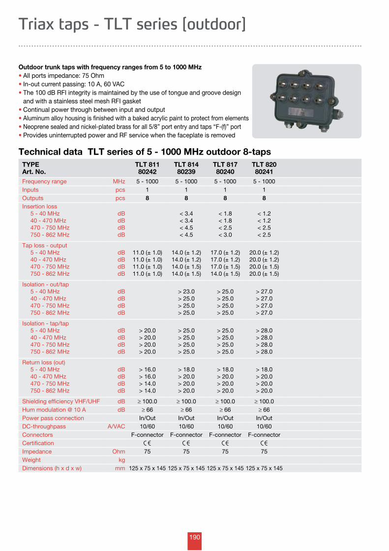
190
Technical data TLT series of 5 - 1000 MHz outdoor 8-taps
Triax taps - TLT series [outdoor]
TYPEArt. No.
TLT 811 80242
TLT 81480239
TLT 81780240
TLT 82080241
Frequency range MHz 5 - 1000 5 - 1000 5 - 1000 5 - 1000Inputs pcs 1 1 1 1Outputs pcs 8 8 8 8Insertion loss 5 - 40 MHz 40 - 470 MHz 470 - 750 MHz 750 - 862 MHz
dBdBdBdB
< 3.4< 3.4< 4.5< 4.5
< 1.8< 1.8< 2.5< 3.0
< 1.2< 1.2< 2.5< 2.5
Tap loss - output 5 - 40 MHz 40 - 470 MHz 470 - 750 MHz 750 - 862 MHz
dBdBdBdB
11.0 (± 1.0) 11.0 (± 1.0) 11.0 (± 1.0) 11.0 (± 1.0)
14.0 (± 1.2) 14.0 (± 1.2) 14.0 (± 1.5) 14.0 (± 1.5)
17.0 (± 1.2) 17.0 (± 1.2) 17.0 (± 1.5) 14.0 (± 1.5)
20.0 (± 1.2) 20.0 (± 1.2) 20.0 (± 1.5) 20.0 (± 1.5)
Isolation - out/tap 5 - 40 MHz 40 - 470 MHz 470 - 750 MHz 750 - 862 MHz
dBdBdBdB
> 23.0> 25.0> 25.0> 25.0
> 25.0> 25.0> 25.0> 25.0
> 27.0> 27.0> 27.0> 27.0
Isolation - tap/tap 5 - 40 MHz 40 - 470 MHz 470 - 750 MHz 750 - 862 MHz
dBdBdBdB
> 20.0> 20.0> 20.0> 20.0
> 25.0> 25.0> 25.0> 25.0
> 25.0> 25.0> 25.0> 25.0
> 28.0> 28.0> 28.0> 28.0
Return loss (out) 5 - 40 MHz 40 - 470 MHz 470 - 750 MHz 750 - 862 MHz
dBdBdBdB
> 16.0> 16.0> 14.0> 14.0
> 18.0> 20.0> 20.0> 20.0
> 18.0> 20.0> 20.0> 20.0
> 18.0> 20.0> 20.0> 20.0
Shielding efficiency VHF/UHF dB ≥ 100.0 ≥ 100.0 ≥ 100.0 ≥ 100.0Hum modulation @ 10 A dB ≥ 66 ≥ 66 ≥ 66 ≥ 66Power pass connection In/Out In/Out In/Out In/OutDC-throughpass A/VAC 10/60 10/60 10/60 10/60 Connectors F-connector F-connector F-connector F-connectorCertificationImpedance Ohm 75 75 75 75Weight kgDimensions (h x d x w) mm 125 x 75 x 145 125 x 75 x 145 125 x 75 x 145 125 x 75 x 145
Outdoor trunk taps with frequency ranges from 5 to 1000 MHz • All ports impedance: 75 Ohm • In-out current passing: 10 A, 60 VAC • The 100 dB RFI integrity is maintained by the use of tongue and groove design and with a stainless steel mesh RFI gasket• Continual power through between input and output • Aluminum alloy housing is finished with a baked acrylic paint to protect from elements • Neoprene sealed and nickel-plated brass for all 5/8” port entry and taps “F-(f)” port • Provides uninterrupted power and RF service when the faceplate is removed
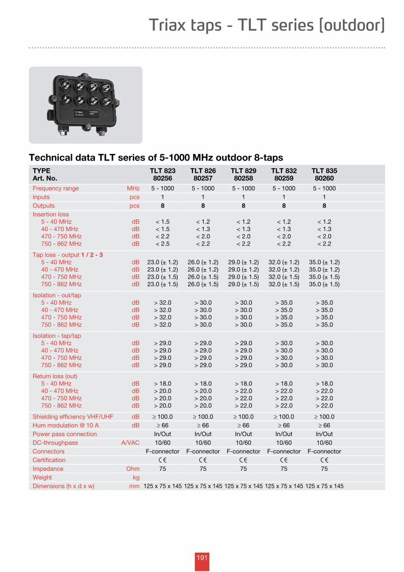
191
Triax taps - TLT series [outdoor]
Technical data TLT series of 5-1000 MHz outdoor 8-tapsTYPEArt. No.
TLT 82380256
TLT 82680257
TLT 82980258
TLT 83280259
TLT 83580260
Frequency range MHz 5 - 1000 5 - 1000 5 - 1000 5 - 1000 5 - 1000Inputs pcs 1 1 1 1 1Outputs pcs 8 8 8 8 8Insertion loss 5 - 40 MHz 40 - 470 MHz 470 - 750 MHz 750 - 862 MHz
dBdBdBdB
< 1.5< 1.5< 2.2< 2.5
< 1.2< 1.3< 2.0< 2.2
< 1.2< 1.3< 2.0< 2.2
< 1.2< 1.3< 2.0< 2.2
< 1.2< 1.3< 2.0< 2.2
Tap loss - output 1 / 2 - 3 5 - 40 MHz 40 - 470 MHz 470 - 750 MHz 750 - 862 MHz
dBdBdBdB
23.0 (± 1.2) 23.0 (± 1.2) 23.0 (± 1.5) 23.0 (± 1.5)
26.0 (± 1.2) 26.0 (± 1.2) 26.0 (± 1.5) 26.0 (± 1.5)
29.0 (± 1.2) 29.0 (± 1.2) 29.0 (± 1.5) 29.0 (± 1.5)
32.0 (± 1.2) 32.0 (± 1.2) 32.0 (± 1.5) 32.0 (± 1.5)
35.0 (± 1.2) 35.0 (± 1.2) 35.0 (± 1.5) 35.0 (± 1.5)
Isolation - out/tap 5 - 40 MHz 40 - 470 MHz 470 - 750 MHz 750 - 862 MHz
dBdBdBdB
> 32.0> 32.0> 32.0> 32.0
> 30.0> 30.0> 30.0> 30.0
> 30.0> 30.0> 30.0> 30.0
> 35.0> 35.0> 35.0> 35.0
> 35.0> 35.0> 35.0> 35.0
Isolation - tap/tap 5 - 40 MHz 40 - 470 MHz 470 - 750 MHz 750 - 862 MHz
dBdBdBdB
> 29.0> 29.0> 29.0> 29.0
> 29.0> 29.0> 29.0> 29.0
> 29.0> 29.0> 29.0> 29.0
> 30.0> 30.0> 30.0> 30.0
> 30.0> 30.0> 30.0> 30.0
Return loss (out) 5 - 40 MHz 40 - 470 MHz 470 - 750 MHz 750 - 862 MHz
dBdBdBdB
> 18.0> 20.0> 20.0> 20.0
> 18.0> 20.0> 20.0> 20.0
> 18.0> 22.0> 22.0> 22.0
> 18.0> 22.0> 22.0> 22.0
> 18.0> 22.0> 22.0> 22.0
Shielding efficiency VHF/UHF dB ≥ 100.0 ≥ 100.0 ≥ 100.0 ≥ 100.0 ≥ 100.0Hum modulation @ 10 A dB ≥ 66 ≥ 66 ≥ 66 ≥ 66 ≥ 66Power pass connection In/Out In/Out In/Out In/Out In/OutDC-throughpass A/VAC 10/60 10/60 10/60 10/60 10/60 Connectors F-connector F-connector F-connector F-connector F-connectorCertificationImpedance Ohm 75 75 75 75 75Weight kgDimensions (h x d x w) mm 125 x 75 x 145 125 x 75 x 145 125 x 75 x 145 125 x 75 x 145 125 x 75 x 145
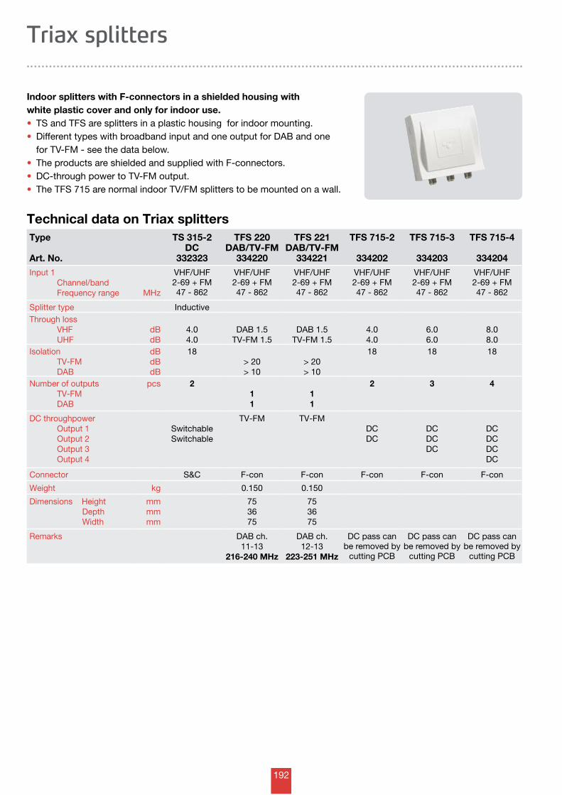
192
Type
Art. No.
TS 315-2DC
332323
TFS 220DAB/TV-FM
334220
TFS 221DAB/TV-FM
334221
TFS 715-2
334202
TFS 715-3
334203
TFS 715-4
334204Input 1 Channel/band Frequency range MHz
VHF/UHF2-69 + FM47 - 862
VHF/UHF2-69 + FM47 - 862
VHF/UHF2-69 + FM47 - 862
VHF/UHF2-69 + FM47 - 862
VHF/UHF2-69 + FM47 - 862
VHF/UHF2-69 + FM47 - 862
Splitter type InductiveThrough loss VHF UHF
dBdB
4.04.0
DAB 1.5TV-FM 1.5
DAB 1.5TV-FM 1.5
4.04.0
6.06.0
8.08.0
Isolation TV-FM DAB
dBdBdB
18> 20> 10
> 20> 10
18 18 18
Number of outputs TV-FM DAB
pcs 211
11
2 3 4
DC throughpower Output 1 Output 2 Output 3 Output 4
SwitchableSwitchable
TV-FM TV-FMDCDC
DCDCDC
DCDCDCDC
Connector S&C F-con F-con F-con F-con F-con
Weight kg 0.150 0.150
Dimensions Height Depth Width
mmmmmm
753675
753675
Remarks DAB ch.11-13
216-240 MHz
DAB ch.12-13
223-251 MHz
DC pass can be removed by
cutting PCB
DC pass can be removed by
cutting PCB
DC pass can be removed by
cutting PCB
Technical data on Triax splitters
Indoor splitters with F-connectors in a shielded housing with white plastic cover and only for indoor use.• TS and TFS are splitters in a plastic housing for indoor mounting. • Different types with broadband input and one output for DAB and one for TV-FM - see the data below. • The products are shielded and supplied with F-connectors. • DC-through power to TV-FM output. • The TFS 715 are normal indoor TV/FM splitters to be mounted on a wall.
Triax splitters
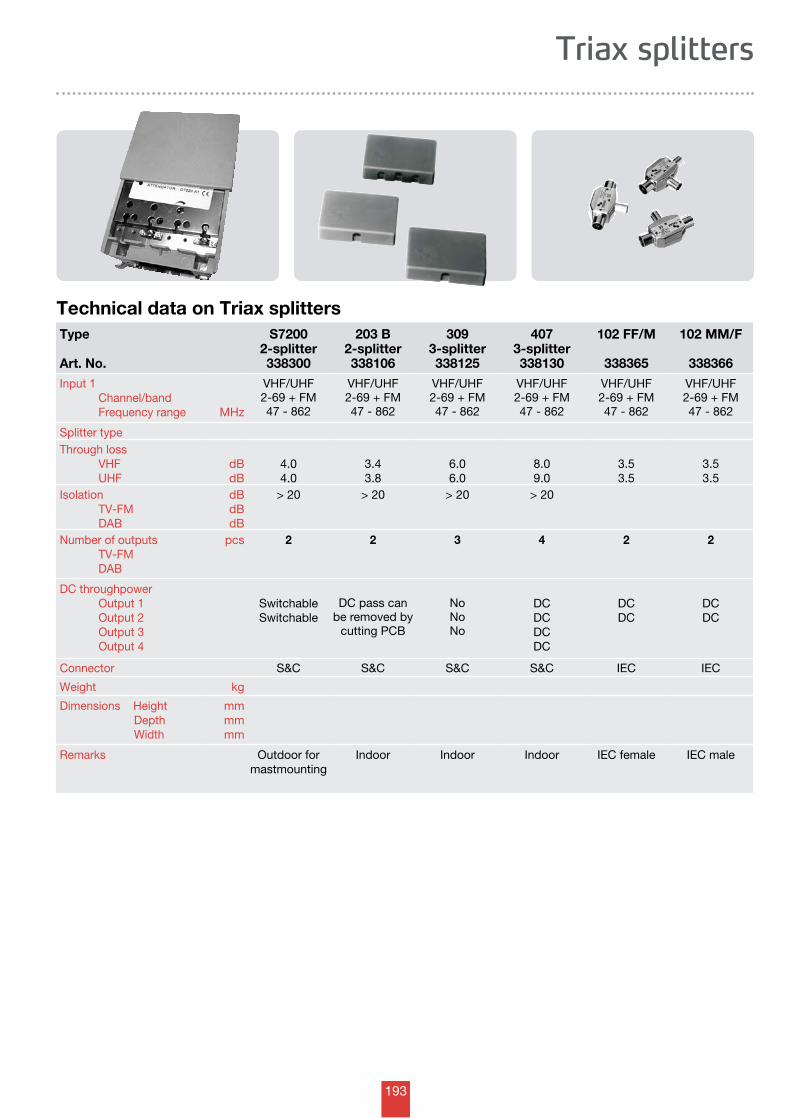
193
Triax splitters
Technical data on Triax splittersType
Art. No.
S72002-splitter338300
203 B2-splitter338106
3093-splitter338125
4073-splitter338130
102 FF/M
338365
102 MM/F
338366Input 1 Channel/band Frequency range MHz
VHF/UHF2-69 + FM47 - 862
VHF/UHF2-69 + FM47 - 862
VHF/UHF2-69 + FM47 - 862
VHF/UHF2-69 + FM47 - 862
VHF/UHF2-69 + FM47 - 862
VHF/UHF2-69 + FM47 - 862
Splitter typeThrough loss VHF UHF
dBdB
4.04.0
3.43.8
6.06.0
8.09.0
3.53.5
3.53.5
Isolation TV-FM DAB
dBdBdB
> 20 > 20 > 20 > 20
Number of outputs TV-FM DAB
pcs 2 2 3 4 2 2
DC throughpower Output 1 Output 2 Output 3 Output 4
SwitchableSwitchable
DC pass can be removed by
cutting PCB
NoNoNo
DCDCDCDC
DCDC
DCDC
Connector S&C S&C S&C S&C IEC IEC
Weight kg
Dimensions Height Depth Width
mmmmmm
Remarks Outdoor formastmounting
Indoor Indoor Indoor IEC female IEC male
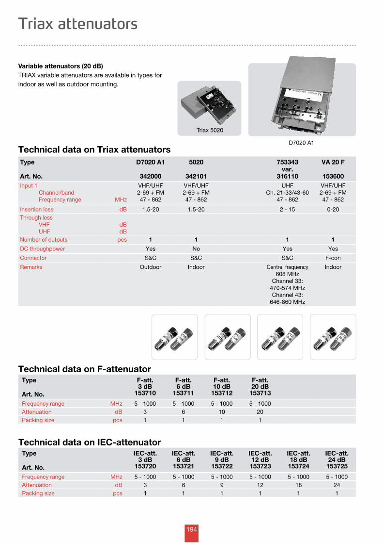
194
Type
Art. No.
D7020 A1
342000
5020
342101
753343var.
316110
VA 20 F
153600Input 1 Channel/band Frequency range MHz
VHF/UHF2-69 + FM47 - 862
VHF/UHF2-69 + FM47 - 862
UHFCh. 21-33/43-60
47 - 862
VHF/UHF2-69 + FM47 - 862
Insertion loss dB 1.5-20 1.5-20 2 - 15 0-20Through loss VHF UHF
dBdB
Number of outputs pcs 1 1 1 1
DC throughpower Yes No Yes Yes
Connector S&C S&C S&C F-con
Remarks Outdoor Indoor Centre frequency608 MHz
Channel 33: 470-574 MHzChannel 43:
646-860 MHz
Indoor
Technical data on Triax attenuators
Variable attenuators (20 dB)TRIAX variable attenuators are available in types for indoor as well as outdoor mounting.
Triax attenuators
Triax 5020
D7020 A1
Type
Art. No.
F-att.3 dB
153710
F-att. 6 dB
153711
F-att. 10 dB
153712
F-att. 20 dB
153713
Frequency range MHz 5 - 1000 5 - 1000 5 - 1000 5 - 1000Attenuation dB 3 6 10 20Packing size pcs 1 1 1 1
Technical data on F-attenuator
Type
Art. No.
IEC-att.3 dB
153720
IEC-att. 6 dB
153721
IEC-att. 9 dB
153722
IEC-att. 12 dB
153723
IEC-att. 18 dB
153724
IEC-att. 24 dB
153725
Frequency range MHz 5 - 1000 5 - 1000 5 - 1000 5 - 1000 5 - 1000 5 - 1000Attenuation dB 3 6 9 12 18 24Packing size pcs 1 1 1 1 1 1
Technical data on IEC-attenuator
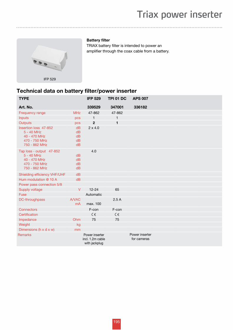
195
Battery filterTRIAX battery filter is intended to power an amplifier through the coax cable from a battery.
Triax power inserter
Technical data on battery filter/power inserter
IFP 529
TYPE
Art. No.
IFP 529
339529
TPI 01 DC
347001
APS 007
336182Frequency range MHz 47-862 47-862Inputs pcs 1 1Outputs pcs 2 1Insertion loss 47-852 5 - 40 MHz 40 - 470 MHz 470 - 750 MHz 750 - 862 MHz
dBdBdBdBdB
2 x 4.0
Tap loss - output 47-852 5 - 40 MHz 40 - 470 MHz 470 - 750 MHz 750 - 862 MHz
dBdBdBdB
4.0
Shielding efficiency VHF/UHF dBHum modulation @ 10 A dBPower pass connection 5/8Supply voltage V 12-24 65Fuse AutomaticDC-throughpass A/VAC
mA max. 1002.5 A
Connectors F-con F-conCertificationImpedance Ohm 75 75Weight kgDimensions (h x d x w) mm
Remarks Power inserter incl. 1.2m cable
with jackplug
Power inserter for cameras
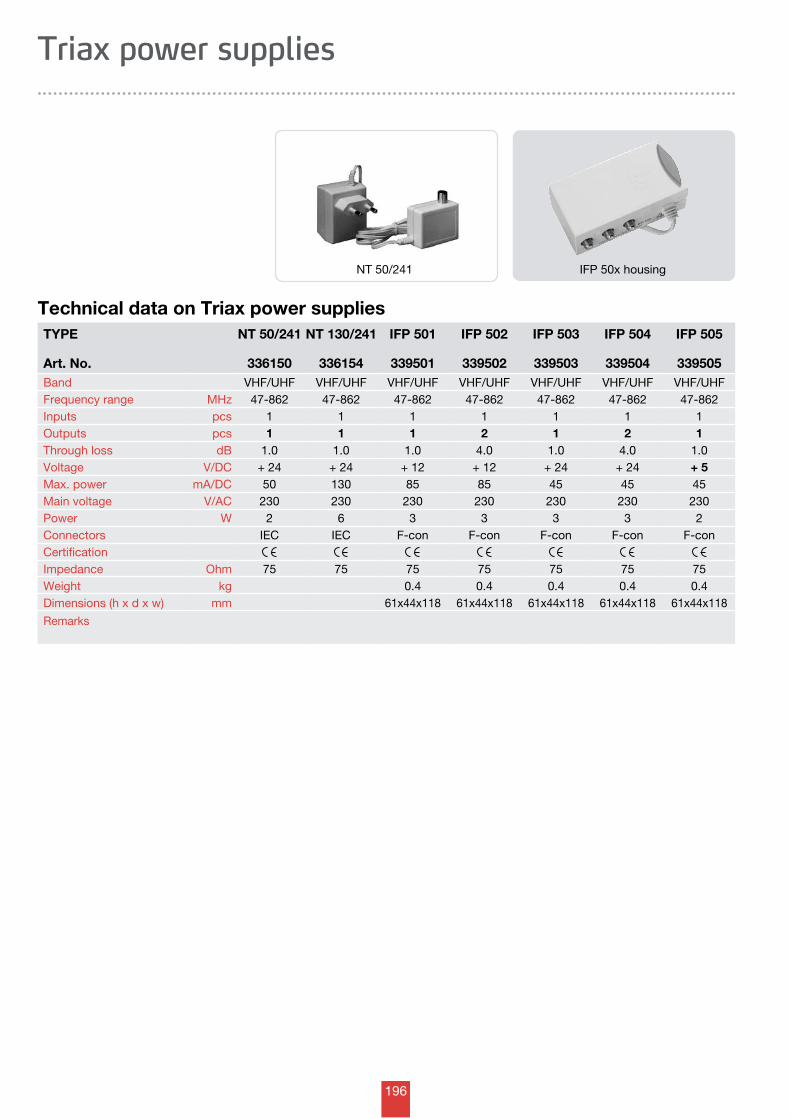
196
Triax power supplies
Technical data on Triax power suppliesTYPE
Art. No.
NT 50/241
336150
NT 130/241
336154
IFP 501
339501
IFP 502
339502
IFP 503
339503
IFP 504
339504
IFP 505
339505Band VHF/UHF VHF/UHF VHF/UHF VHF/UHF VHF/UHF VHF/UHF VHF/UHFFrequency range MHz 47-862 47-862 47-862 47-862 47-862 47-862 47-862Inputs pcs 1 1 1 1 1 1 1Outputs pcs 1 1 1 2 1 2 1Through loss dB 1.0 1.0 1.0 4.0 1.0 4.0 1.0Voltage V/DC + 24 + 24 + 12 + 12 + 24 + 24 + 5Max. power mA/DC 50 130 85 85 45 45 45Main voltage V/AC 230 230 230 230 230 230 230Power W 2 6 3 3 3 3 2Connectors IEC IEC F-con F-con F-con F-con F-conCertificationImpedance Ohm 75 75 75 75 75 75 75Weight kg 0.4 0.4 0.4 0.4 0.4Dimensions (h x d x w) mm 61x44x118 61x44x118 61x44x118 61x44x118 61x44x118
Remarks
NT 50/241 IFP 50x housing
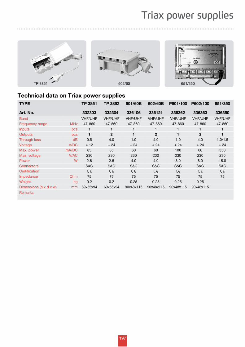
197
Triax power supplies
Technical data on Triax power suppliesTYPE
Art. No.
TP 3851
332303
TP 3852
332304
601/60B
336106
602/60B
336121
P601/100
336362
P602/100
336363
651/350
336350Band VHF/UHF VHF/UHF VHF/UHF VHF/UHF VHF/UHF VHF/UHF VHF/UHFFrequency range MHz 47-860 47-860 47-860 47-860 47-860 47-860 47-860Inputs pcs 1 1 1 1 1 1 1Outputs pcs 1 2 1 2 1 2 1Through loss dB 0.5 4.0 1.0 4.0 1.0 4.0 1.0/1.5Voltage V/DC + 12 + 24 + 24 + 24 + 24 + 24 + 24Max. power mA/DC 85 85 60 60 100 60 350Main voltage V/AC 230 230 230 230 230 230 230Power W 2.6 2.6 4.0 4.0 8.0 8.0 15.0Connectors S&C S&C S&C S&C S&C S&C S&CCertificationImpedance Ohm 75 75 75 75 75 75 75Weight kg 0.2 0.2 0.25 0.25 0.25 0.25Dimensions (h x d x w) mm 69x55x94 69x55x94 90x48x115 90x48x115 90x48x115 90x48x115
Remarks
TP 3851 602/60 651/350
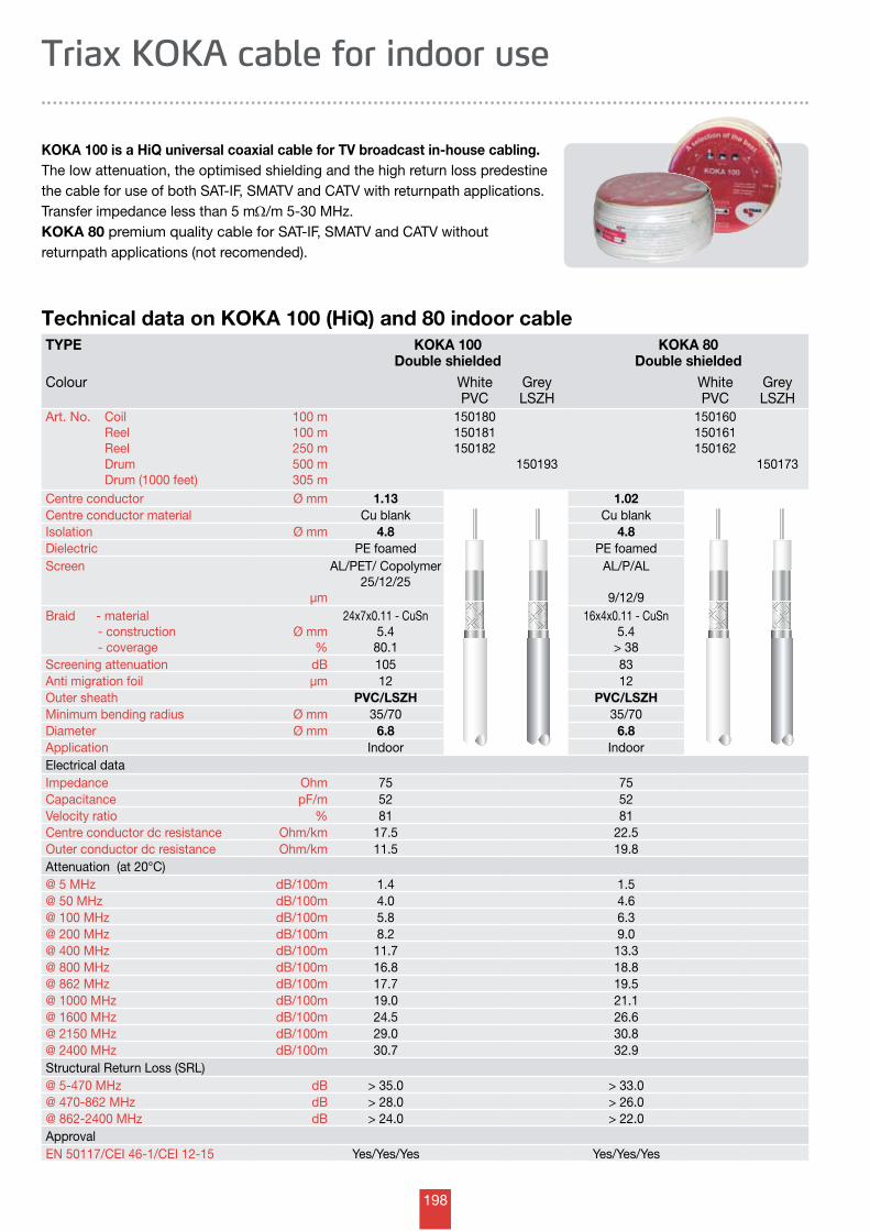
198
Technical data on KOKA 100 (HiQ) and 80 indoor cable
KOKA 100 is a HiQ universal coaxial cable for TV broadcast in-house cabling.The low attenuation, the optimised shielding and the high return loss predestine the cable for use of both SAT-IF, SMATV and CATV with returnpath applications.Transfer impedance less than 5 mW/m 5-30 MHz.KOKA 80 premium quality cable for SAT-IF, SMATV and CATV without returnpath applications (not recomended).
Triax KOKA cable for indoor use
TYPE KOKA 100Double shielded
KOKA 80Double shielded
Colour WhitePVC
GreyLSZH
WhitePVC
GreyLSZH
Art. No. Coil Reel Reel Drum Drum (1000 feet)
100 m100 m250 m500 m305 m
150180150181150182
150193
150160150161150162
150173
Centre conductor Ø mm 1.13 1.02Centre conductor material Cu blank Cu blankIsolation Ø mm 4.8 4.8 Dielectric PE foamed PE foamedScreen
µm
AL/PET/ Copolymer25/12/25
AL/P/AL
9/12/9Braid - material - construction - coverage
Ø mm%
24x7x0.11 - CuSn5.4
80.1
16x4x0.11 - CuSn5.4
> 38Screening attenuation dB 105 83Anti migration foil µm 12 12Outer sheath PVC/LSZH PVC/LSZHMinimum bending radius Ø mm 35/70 35/70Diameter Ø mm 6.8 6.8Application Indoor IndoorElectrical dataImpedance Ohm 75 75Capacitance pF/m 52 52Velocity ratio % 81 81Centre conductor dc resistance Ohm/km 17.5 22.5Outer conductor dc resistance Ohm/km 11.5 19.8Attenuation (at 20°C)@ 5 MHz dB/100m 1.4 1.5@ 50 MHz dB/100m 4.0 4.6@ 100 MHz dB/100m 5.8 6.3@ 200 MHz dB/100m 8.2 9.0@ 400 MHz dB/100m 11.7 13.3@ 800 MHz dB/100m 16.8 18.8@ 862 MHz dB/100m 17.7 19.5@ 1000 MHz dB/100m 19.0 21.1@ 1600 MHz dB/100m 24.5 26.6@ 2150 MHz dB/100m 29.0 30.8@ 2400 MHz dB/100m 30.7 32.9Structural Return Loss (SRL)@ 5-470 MHz dB > 35.0 > 33.0@ 470-862 MHz dB > 28.0 > 26.0@ 862-2400 MHz dB > 24.0 > 22.0ApprovalEN 50117/CEI 46-1/CEI 12-15 Yes/Yes/Yes Yes/Yes/Yes
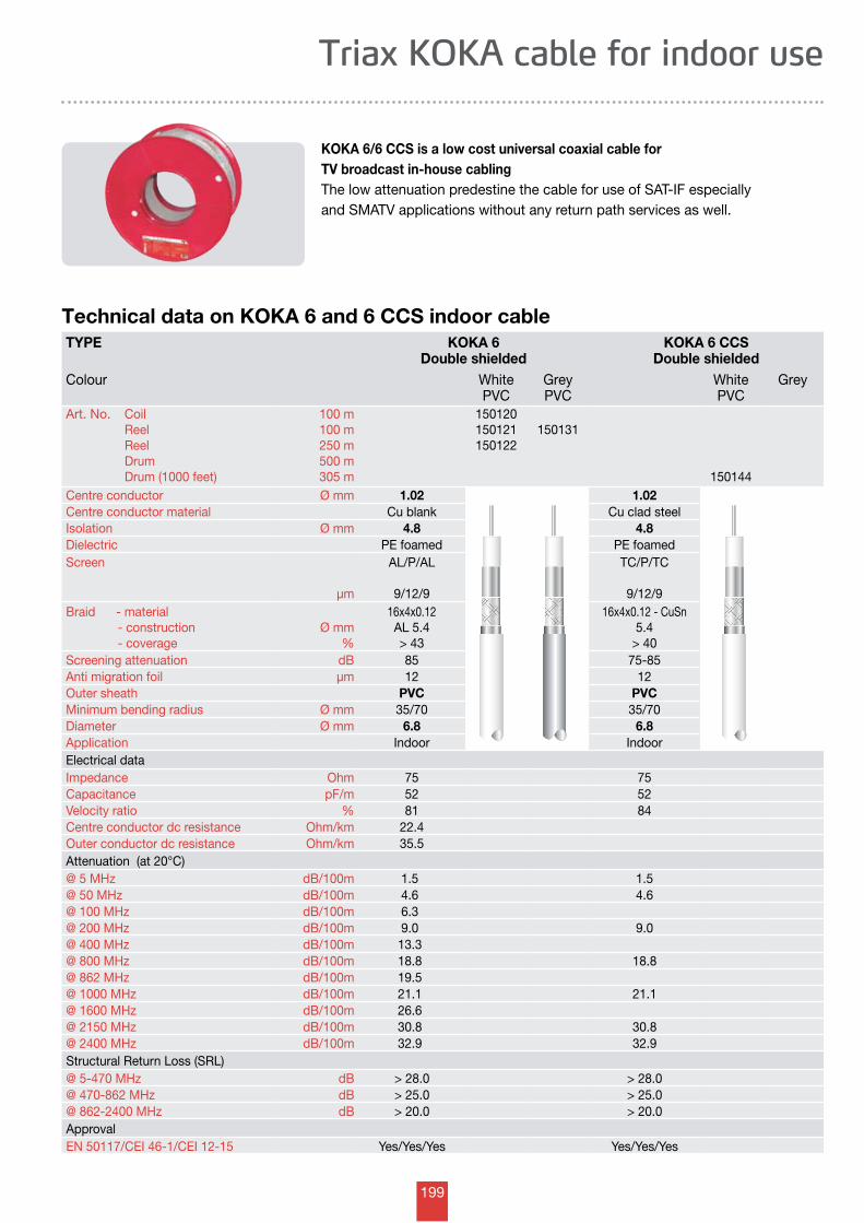
199
Triax KOKA cable for indoor use
Technical data on KOKA 6 and 6 CCS indoor cable
KOKA 6/6 CCS is a low cost universal coaxial cable for TV broadcast in-house cablingThe low attenuation predestine the cable for use of SAT-IF especially and SMATV applications without any return path services as well.
TYPE KOKA 6Double shielded
KOKA 6 CCSDouble shielded
Colour WhitePVC
GreyPVC
WhitePVC
Grey
Art. No. Coil Reel Reel Drum Drum (1000 feet)
100 m100 m250 m500 m305 m
150120150121150122
150131
150144Centre conductor Ø mm 1.02 1.02Centre conductor material Cu blank Cu clad steelIsolation Ø mm 4.8 4.8 Dielectric PE foamed PE foamedScreen
µm
AL/P/AL
9/12/9
TC/P/TC
9/12/9Braid - material - construction - coverage
Ø mm%
16x4x0.12AL 5.4> 43
16x4x0.12 - CuSn5.4
> 40Screening attenuation dB 85 75-85Anti migration foil µm 12 12Outer sheath PVC PVCMinimum bending radius Ø mm 35/70 35/70Diameter Ø mm 6.8 6.8Application Indoor IndoorElectrical dataImpedance Ohm 75 75Capacitance pF/m 52 52Velocity ratio % 81 84Centre conductor dc resistance Ohm/km 22.4Outer conductor dc resistance Ohm/km 35.5Attenuation (at 20°C)@ 5 MHz dB/100m 1.5 1.5@ 50 MHz dB/100m 4.6 4.6@ 100 MHz dB/100m 6.3@ 200 MHz dB/100m 9.0 9.0@ 400 MHz dB/100m 13.3@ 800 MHz dB/100m 18.8 18.8@ 862 MHz dB/100m 19.5@ 1000 MHz dB/100m 21.1 21.1@ 1600 MHz dB/100m 26.6@ 2150 MHz dB/100m 30.8 30.8@ 2400 MHz dB/100m 32.9 32.9Structural Return Loss (SRL)@ 5-470 MHz dB > 28.0 > 28.0@ 470-862 MHz dB > 25.0 > 25.0@ 862-2400 MHz dB > 20.0 > 20.0ApprovalEN 50117/CEI 46-1/CEI 12-15 Yes/Yes/Yes Yes/Yes/Yes
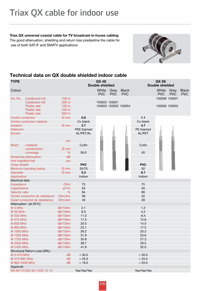
200
Technical data on QX double shielded indoor cable
Triax QX universal coaxial cable for TV broadcast in-house cablingThe good attenuation, shielding and return loss predestine the cable for use of both SAT-IF and SMATV applications
Triax QX cable for indoor use
TYPE QX 4SDouble shielded
QX 5SDouble shielded
Colour WhitePVC
GreyPVC
BlackPVC
WhitePVC
GreyPVC
BlackPVC
Art. No. Cardboard roll Cardboard roll Plastic reel Plastic reel Plastic reel
100 m200 m100 m250 m500 m
150022150053
150021150052 150054
150008
150056
150007
150055
Centre conductor Ø mm 0.8 1.1Centre conductor material Cu blank Cu blankIsolation Ø mm 3.7 4.7 Dielectric PEE foamed PE foamedScreen
µm
AL/PET/AL AL/PET
Braid - material - construction - coverage
Ø mm%
CuSn
56.0
CuSn
45Screening attenuation dBAnti migration foil µmOuter sheath PVC PVCMinimum bending radius Ø mm 35/70 50Diameter Ø mm 5.3 6.7Application Indoor IndoorElectrical dataImpedance Ohm 75 75Capacitance pF/m 55 55Velocity ratio % 84 80Centre conductor dc resistance Ohm/km 38 22Outer conductor dc resistance Ohm/km 40 28Attenuation (at 20°C)@ 5 MHz dB/100m 2.1 1.3@ 50 MHz dB/100m 6.0 4.2@ 200 MHz dB/100m 11.0 8.4@ 470 MHz dB/100m 17.5 12.8@ 600 MHz dB/100m 20.5 14.5@ 800 MHz dB/100m 23.1 17.5@ 1000 MHz dB/100m 26.2 20.3@ 1350 MHz dB/100m 31.9 23.6@ 1750 MHz dB/100m 35.8 27.3@ 2050 MHz dB/100m 38.7 29.5@ 2400 MHz dB/100m 41.9 32.0Structural Return Loss (SRL)@ 5-470 MHz dB > 30.0 > 30.0@ 470-862 MHz dB > 25.0 > 25.0@ 862-2400 MHz dB > 18.0 > 20.0ApprovalEN 50117/CEI 46-1/CEI 12-15 Yes/Yes/Yes Yes/Yes/Yes
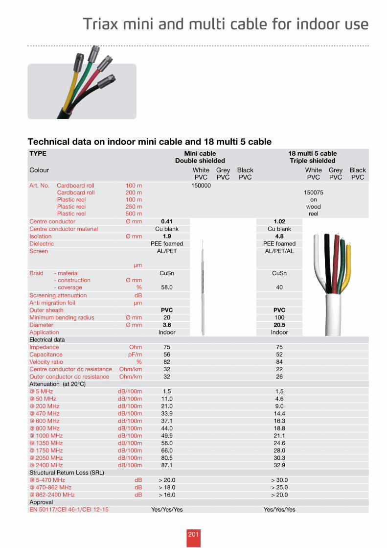
201
TYPE Mini cableDouble shielded
18 multi 5 cableTriple shielded
Colour WhitePVC
GreyPVC
BlackPVC
WhitePVC
GreyPVC
BlackPVC
Art. No. Cardboard roll Cardboard roll Plastic reel Plastic reel Plastic reel
100 m200 m100 m250 m500 m
150000150075
on wood reel
Centre conductor Ø mm 0.41 1.02Centre conductor material Cu blank Cu blankIsolation Ø mm 1.9 4.8 Dielectric PEE foamed PEE foamedScreen
µm
AL/PET AL/PET/AL
Braid - material - construction - coverage
Ø mm%
CuSn
58.0
CuSn
40Screening attenuation dBAnti migration foil µmOuter sheath PVC PVCMinimum bending radius Ø mm 20 100Diameter Ø mm 3.6 20.5Application Indoor IndoorElectrical dataImpedance Ohm 75 75Capacitance pF/m 56 52Velocity ratio % 82 84Centre conductor dc resistance Ohm/km 32 22Outer conductor dc resistance Ohm/km 32 26Attenuation (at 20°C)@ 5 MHz dB/100m 1.5 1.5@ 50 MHz dB/100m 11.0 4.6@ 200 MHz dB/100m 21.0 9.0@ 470 MHz dB/100m 33.9 14.4@ 600 MHz dB/100m 37.1 16.3@ 800 MHz dB/100m 44.0 18.8@ 1000 MHz dB/100m 49.9 21.1@ 1350 MHz dB/100m 58.0 24.6@ 1750 MHz dB/100m 66.0 28.0@ 2050 MHz dB/100m 80.5 30.3@ 2400 MHz dB/100m 87.1 32.9Structural Return Loss (SRL)@ 5-470 MHz dB > 20.0 > 30.0@ 470-862 MHz dB > 18.0 > 25.0@ 862-2400 MHz dB > 16.0 > 20.0ApprovalEN 50117/CEI 46-1/CEI 12-15 Yes/Yes/Yes Yes/Yes/Yes
Triax mini and multi cable for indoor use
Technical data on indoor mini cable and 18 multi 5 cable
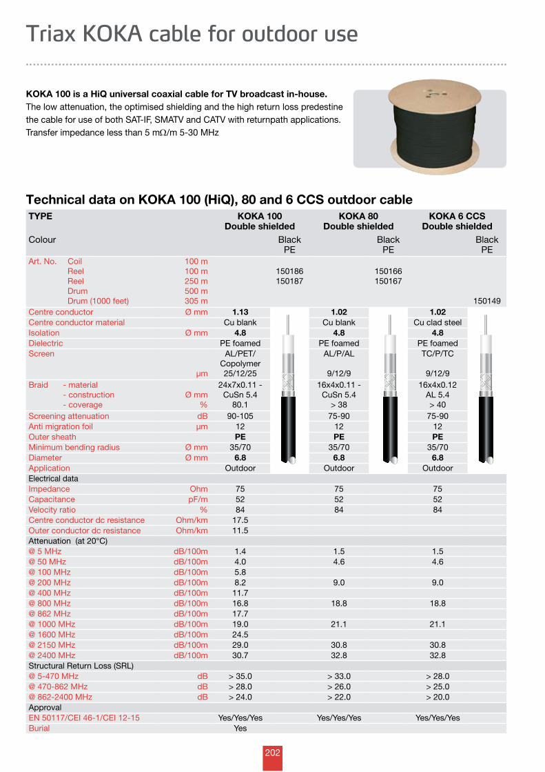
202
Technical data on KOKA 100 (HiQ), 80 and 6 CCS outdoor cable
KOKA 100 is a HiQ universal coaxial cable for TV broadcast in-house.The low attenuation, the optimised shielding and the high return loss predestine the cable for use of both SAT-IF, SMATV and CATV with returnpath applications.Transfer impedance less than 5 mW/m 5-30 MHz
Triax KOKA cable for outdoor use
TYPE KOKA 100Double shielded
KOKA 80Double shielded
KOKA 6 CCSDouble shielded
Colour BlackPE
BlackPE
BlackPE
Art. No. Coil Reel Reel Drum Drum (1000 feet)
100 m100 m250 m500 m305 m
150186150187
150166150167
150149Centre conductor Ø mm 1.13 1.02 1.02Centre conductor material Cu blank Cu blank Cu clad steelIsolation Ø mm 4.8 4.8 4.8 Dielectric PE foamed PE foamed PE foamedScreen
µm
AL/PET/ Copolymer25/12/25
AL/P/AL
9/12/9
TC/P/TC
9/12/9Braid - material - construction - coverage
Ø mm%
24x7x0.11 - CuSn 5.4
80.1
16x4x0.11 - CuSn 5.4
> 38
16x4x0.12AL 5.4> 40
Screening attenuation dB 90-105 75-90 75-90Anti migration foil µm 12 12 12Outer sheath PE PE PEMinimum bending radius Ø mm 35/70 35/70 35/70Diameter Ø mm 6.8 6.8 6.8Application Outdoor Outdoor OutdoorElectrical dataImpedance Ohm 75 75 75Capacitance pF/m 52 52 52Velocity ratio % 84 84 84Centre conductor dc resistance Ohm/km 17.5Outer conductor dc resistance Ohm/km 11.5Attenuation (at 20°C)@ 5 MHz dB/100m 1.4 1.5 1.5@ 50 MHz dB/100m 4.0 4.6 4.6@ 100 MHz dB/100m 5.8@ 200 MHz dB/100m 8.2 9.0 9.0@ 400 MHz dB/100m 11.7@ 800 MHz dB/100m 16.8 18.8 18.8@ 862 MHz dB/100m 17.7@ 1000 MHz dB/100m 19.0 21.1 21.1@ 1600 MHz dB/100m 24.5@ 2150 MHz dB/100m 29.0 30.8 30.8@ 2400 MHz dB/100m 30.7 32.8 32.8Structural Return Loss (SRL)@ 5-470 MHz dB > 35.0 > 33.0 > 28.0@ 470-862 MHz dB > 28.0 > 26.0 > 25.0@ 862-2400 MHz dB > 24.0 > 22.0 > 20.0ApprovalEN 50117/CEI 46-1/CEI 12-15 Yes/Yes/Yes Yes/Yes/Yes Yes/Yes/YesBurial Yes
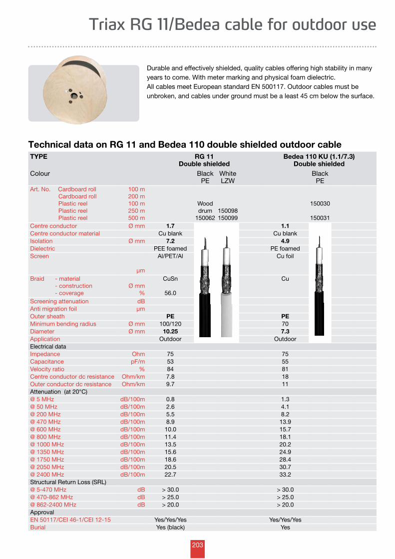
203
Technical data on RG 11 and Bedea 110 double shielded outdoor cable
Triax RG 11/Bedea cable for outdoor use
Durable and effectively shielded, quality cables offering high stability in many years to come. With meter marking and physical foam dielectric. All cables meet European standard EN 500117. Outdoor cables must be unbroken, and cables under ground must be a least 45 cm below the surface.
TYPE RG 11Double shielded
Bedea 110 KU (1.1/7.3)Double shielded
Colour BlackPE
WhiteLZW
BlackPE
Art. No. Cardboard roll Cardboard roll Plastic reel Plastic reel Plastic reel
100 m200 m100 m250 m500 m
Wood drum
150062150098150099
150030
150031Centre conductor Ø mm 1.7 1.1Centre conductor material Cu blank Cu blankIsolation Ø mm 7.2 4.9 Dielectric PEE foamed PE foamedScreen
µm
Al/PET/Al Cu foil
Braid - material - construction - coverage
Ø mm%
CuSn
56.0
Cu
Screening attenuation dBAnti migration foil µmOuter sheath PE PEMinimum bending radius Ø mm 100/120 70Diameter Ø mm 10.25 7.3Application Outdoor OutdoorElectrical dataImpedance Ohm 75 75Capacitance pF/m 53 55Velocity ratio % 84 81Centre conductor dc resistance Ohm/km 7.8 18Outer conductor dc resistance Ohm/km 9.7 11Attenuation (at 20°C)@ 5 MHz dB/100m 0.8 1.3@ 50 MHz dB/100m 2.6 4.1@ 200 MHz dB/100m 5.5 8.2@ 470 MHz dB/100m 8.9 13.9@ 600 MHz dB/100m 10.0 15.7@ 800 MHz dB/100m 11.4 18.1@ 1000 MHz dB/100m 13.5 20.2@ 1350 MHz dB/100m 15.6 24.9@ 1750 MHz dB/100m 18.6 28.4@ 2050 MHz dB/100m 20.5 30.7@ 2400 MHz dB/100m 22.7 33.2Structural Return Loss (SRL)@ 5-470 MHz dB > 30.0 > 30.0@ 470-862 MHz dB > 25.0 > 25.0@ 862-2400 MHz dB > 20.0 > 20.0ApprovalEN 50117/CEI 46-1/CEI 12-15 Yes/Yes/Yes Yes/Yes/YesBurial Yes (black) Yes
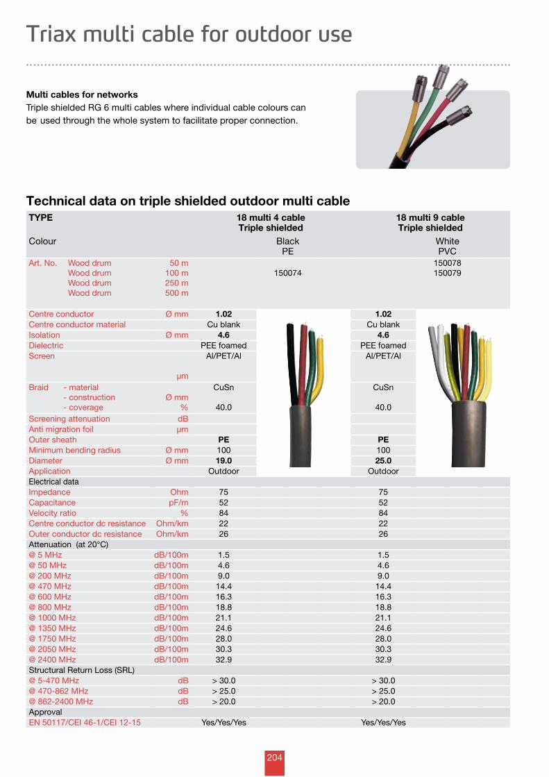
204
TYPE 18 multi 4 cableTriple shielded
18 multi 9 cableTriple shielded
Colour BlackPE
WhitePVC
Art. No. Wood drum Wood drum Wood drum Wood drum
50 m100 m250 m500 m
150074150078150079
Centre conductor Ø mm 1.02 1.02Centre conductor material Cu blank Cu blankIsolation Ø mm 4.6 4.6 Dielectric PEE foamed PEE foamedScreen
µm
Al/PET/Al Al/PET/Al
Braid - material - construction - coverage
Ø mm%
CuSn
40.0
CuSn
40.0Screening attenuation dBAnti migration foil µmOuter sheath PE PEMinimum bending radius Ø mm 100 100Diameter Ø mm 19.0 25.0Application Outdoor OutdoorElectrical dataImpedance Ohm 75 75Capacitance pF/m 52 52Velocity ratio % 84 84Centre conductor dc resistance Ohm/km 22 22Outer conductor dc resistance Ohm/km 26 26Attenuation (at 20°C)@ 5 MHz dB/100m 1.5 1.5@ 50 MHz dB/100m 4.6 4.6@ 200 MHz dB/100m 9.0 9.0@ 470 MHz dB/100m 14.4 14.4@ 600 MHz dB/100m 16.3 16.3@ 800 MHz dB/100m 18.8 18.8@ 1000 MHz dB/100m 21.1 21.1@ 1350 MHz dB/100m 24.6 24.6@ 1750 MHz dB/100m 28.0 28.0@ 2050 MHz dB/100m 30.3 30.3@ 2400 MHz dB/100m 32.9 32.9Structural Return Loss (SRL)@ 5-470 MHz dB > 30.0 > 30.0@ 470-862 MHz dB > 25.0 > 25.0@ 862-2400 MHz dB > 20.0 > 20.0ApprovalEN 50117/CEI 46-1/CEI 12-15 Yes/Yes/Yes Yes/Yes/Yes
Technical data on triple shielded outdoor multi cable
Multi cables for networksTriple shielded RG 6 multi cables where individual cable colours can be used through the whole system to facilitate proper connection.
Triax multi cable for outdoor use
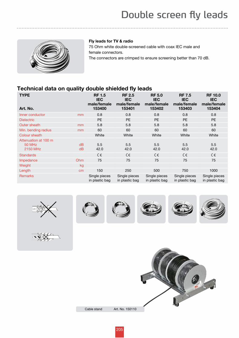
205
TYPE
Art. No.
RF 1.5 IEC
male/female153400
RF 2.5 IEC
male/female153401
RF 5.0 IEC
male/female153402
RF 7.5 IEC
male/female153403
RF 10.0 IEC
male/female153404
Inner conductor mm 0.8 0.8 0.8 0.8 0.8Dielectric PE PE PE PE PEOuter sheath mm 5.8 5.8 5.8 5.8 5.8Min. bending radius mm 60 60 60 60 60Colour sheath White White White White WhiteAttenuation at 100 m 50 MHz 2150 MHz
dBdB
5.542.0
5.542.0
5.542.0
5.542.0
5.542.0
Standards Impedance Ohm 75 75 75 75 75Weight kgLength cm 150 250 500 750 1000
Remarks Single pieces in plastic bag
Single pieces in plastic bag
Single pieces in plastic bag
Single pieces in plastic bag
Single pieces in plastic bag
Cable stand Art. No. 150110
Technical data on quality double shielded fly leads
Double screen fly leads
Fly leads for TV & radio75 Ohm white double-screened cable with coax IEC male andfemale connectors.The connectors are crimped to ensure screening better than 70 dB.
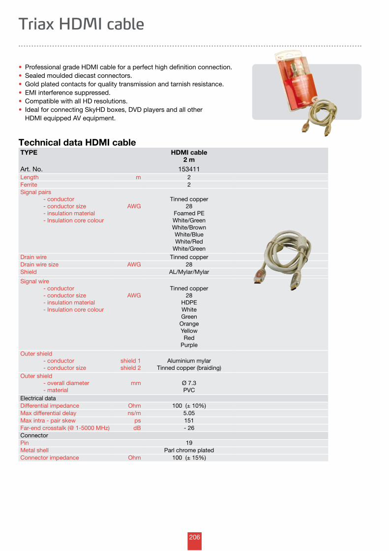
206
TYPE HDMI cable 2 m
Art. No. 153411Length m 2Ferrite 2Signal pairs - conductor - conductor size - insulation material - Insulation core colour
AWGTinned copper
28Foamed PEWhite/GreenWhite/BrownWhite/BlueWhite/Red
White/GreenDrain wire Tinned copperDrain wire size AWG 28Shield AL/Mylar/Mylar
Signal wire - conductor - conductor size - insulation material - Insulation core colour
AWGTinned copper
28HDPEWhiteGreen
OrangeYellowRed
Purple
Outer shield - conductor - conductor size
shield 1shield 2
Aluminium mylarTinned copper (braiding)
Outer shield - overall diameter - material
mm Ø 7.3PVC
Electrical dataDifferential impedance Ohm 100 (± 10%)Max differential delay ns/m 5.05Max intra - pair skew ps 151Far-end crosstalk (@ 1-5000 MHz) dB - 26ConnectorPin 19Metal shell Parl chrome platedConnector impedance Ohm 100 (± 15%)
Technical data HDMI cable
• Professional grade HDMI cable for a perfect high definition connection.• Sealed moulded diecast connectors.• Gold plated contacts for quality transmission and tarnish resistance.• EMI interference suppressed.• Compatible with all HD resolutions.• Ideal for connecting SkyHD boxes, DVD players and all other HDMI equipped AV equipment.
Triax HDMI cable
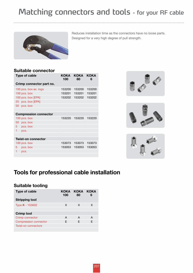
207
Suitable connectorType of cable KOKA
100KOKA
80KOKA
6Crimp connector part no.
100 pcs. box ex. logo 153200 153200 153200100 pcs. box 153201 153201 153201100 pcs. box [EPA] 153202 153202 15320225 pcs. box [EPA]50 pcs. box
Compression connector100 pcs. box 153220 153220 15322050 pcs. box5 pcs. box1 pcs.
Twist-on connector100 pcs. box 153073 153073 1530735 pcs. box 153053 153053 1530531 pcs.
Suitable toolingType of cable KOKA
100KOKA
80KOKA
6Stripping tool
Type K - 153602 X X X
Crimp toolCrimp connector A A ACompression connector E E ETwist-on connectors
Reduces installation time as the connectors have no loose parts.
Designed for a very high degree of pull strength.
Matching connectors and tools - for your RF cable
Tools for professional cable installation
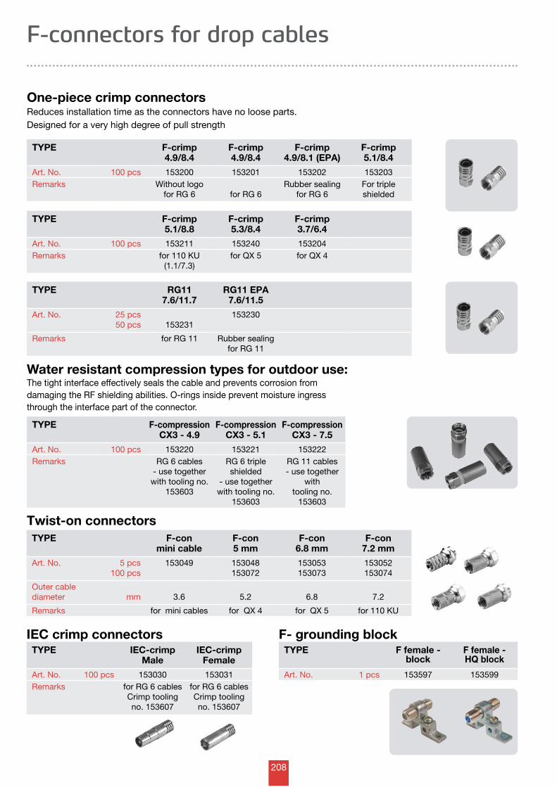
208
Twist-on connectorsTYPE F-con
mini cableF-con5 mm
F-con 6.8 mm
F-con 7.2 mm
Art. No. 5 pcs100 pcs
153049 153048153072
153053153073
153052153074
Outer cablediameter mm 3.6 5.2 6.8 7.2
Remarks for mini cables for QX 4 for QX 5 for 110 KU
One-piece crimp connectorsReduces installation time as the connectors have no loose parts. Designed for a very high degree of pull strength
TYPE F-crimp4.9/8.4
F-crimp4.9/8.4
F-crimp4.9/8.1 (EPA)
F-crimp5.1/8.4
Art. No. 100 pcs 153200 153201 153202 153203Remarks Without logo
for RG 6 for RG 6 Rubber sealing
for RG 6For triple shielded
TYPE F-crimp5.1/8.8
F-crimp5.3/8.4
F-crimp3.7/6.4
Art. No. 100 pcs 153211 153240 153204Remarks for 110 KU
(1.1/7.3)for QX 5 for QX 4
Water resistant compression types for outdoor use: The tight interface effectively seals the cable and prevents corrosion from damaging the RF shielding abilities. O-rings inside prevent moisture ingress through the interface part of the connector.
TYPE F-compressionCX3 - 4.9
F-compressionCX3 - 5.1
F-compressionCX3 - 7.5
Art. No. 100 pcs 153220 153221 153222Remarks RG 6 cables
- use together with tooling no.
153603
RG 6 triple shielded
- use together with tooling no.
153603
RG 11 cables- use together
with tooling no.
153603
TYPE RG117.6/11.7
RG11 EPA7.6/11.5
Art. No. 25 pcs50 pcs 153231
153230
Remarks for RG 11 Rubber sealingfor RG 11
F- grounding blockTYPE F female -
blockF female - HQ block
Art. No. 1 pcs 153597 153599
IEC crimp connectorsTYPE IEC-crimp
MaleIEC-crimp
Female
Art. No. 100 pcs 153030 153031Remarks for RG 6 cables
Crimp tooling no. 153607
for RG 6 cablesCrimp tooling no. 153607
F-connectors for drop cables
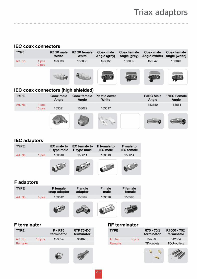
209
IEC adaptorsTYPE IEC male to
F-type maleIEC female toF-type male
F female toIEC male
F male toIEC female
Art. No. 1 pcs 153610 153611 153613 153614
F adaptorsTYPE F female
snap adaptorF angle adaptor
F male - male
F female - female
Art. No. 5 pcs 153612 153592 153596 153593
F terminatorTYPE F - R75
terminatorRTF 75-DCterminator
Art. No. 10 pcs 153054 364025Remarks
IEC coax connectorsTYPE RZ 20 male
WhiteRZ 20 female
WhiteCoax male
Angle (grey)Coax female Angle (grey)
Coax male Angle (white)
Coax female Angle (white)
Art. No. 1 pcs10 pcs
153033 153038 153032 153035 153042 153043
IEC coax connectors (high shielded)TYPE Coax male
AngleCoax female
AnglePlastic cover
WhiteF/IEC Male
AngleF/IEC Female
Angle
Art. No. 1 pcs10 pcs 153021 153022 153017
153550 153551
Triax adaptors
RF terminatorTYPE R75 - 75W
terminatorR1000 - 75Wterminator
Art. No. 5 pcs 342503 342504Remarks TD-outlets TOU-outlets

210
Tools for professional cable mounting
Stripping tools: With rotary cable strippers, preparation of cable is reduced to a single operation resulting in precise stripping in the dimensions matching exactly with the connector. The non-expensive stripping tools are pre-adjusted for RG 6 and RG 11 cables respectively.
Art. No. 153607CRP 106H crimp tool- is for .324” (8.2 mm) and .360” (9.2 mm) one-piece F-connectors and EPA typically used with RG 6 and QX 5 cables
A BArt. No. 153609CRP 106F crimp tool- is for .324” (8.2 mm) and .475” (11.9 mm) one-piece F-connectors typically used with RG 11 cables
CArt. No. 153605Crimp tool universal - is for two-piece F-connectors.
E KArt. No. 153602
LArt. No. 153601
RG 6 cables RG 11 cables
Art. No. 153633Mounting tool for F-connectors: The plastic handle gives you a good grip of the connector and is more convenient to work with than the metal types of mounting tools. Especially for one-piece and compression type of F-connectors.
Art. No. 153634Cable support tool: While mounting the connector this unique rubber tool gives you a good grip of the cable, and with no risk of damaging the cable. Support cables with dimensions 3-12 mm.
Art. No. 153606Mounting T-tool: With female thread. Efficient for two-piece and twist-on types of F-connectors.
Art. No. 153632Torque wrench spanner: The spanner ensures a proper installation in accordance with SCTE standards, minimizing the risk of heavy screening leakage. When using F- connectors outdoors SCTE recommends a torque of 3,4 - 5,6 Nm.
Art. No. 153608TRIAX F-key: Indispensable to anyone working with F-connectors
Art. No. 153603Compression tool universal RG 6/RG 11 is used for compression type F-connectors for outdoor use and ensures waterresistant connections.
Tools for stripping, crimping and mountingThe most efficient and stable connection between cable and connector is obtained, when crimping is done in one, swift operation (no re-crimping) and with a tool in the exact, right size. Triax’s range of F-connector tools is easy to use and reduces stripping, crimping and mounting to a few, quick and precise operations.
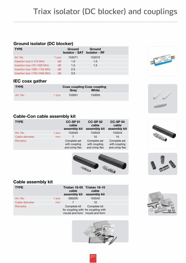
211
TYPE CC-SP 01cable
assembly kit
CC-SP 02cable
assembly kit
CC-SP 04cable
assembly kitArt. No. 1 pcs 153540 153542 153544Cable diameter mm 7 10 15Remarks Complete set
with coupling and crimp flex
Complete set with coupling and crimp flex
Complete set with coupling and crimp flex
Ground isolator (DC blocker)TYPE Ground
Isolator - SATGround
Isolator - RF
Art. No. 1 pcs 153571 153572Insertion loss 5-470 MHz dB 1.0 1.0Insertion loss 470-1000 MHz dB 1.5 1.5Insertion loss 1000-1750 MHz dB 2.5Insertion loss 1750-2400 MHz dB 3.5
Triax isolator (DC blocker) and couplings
IEC coax gatherTYPE Coax coupling
GreyCoax coupling
White
Art. No. 1 pcs 153051 153055
Cable-Con cable assembly kit
Cable assembly kitTYPE Triatan 18-05
cable assembly kit
Triatan 18-10cable
assembly kitArt. No. 1 pcs 590205 153542Cable diameter mm 7 10Remarks Complete kit
for coupling with mould and form
Complete kitfor coupling with mould and form
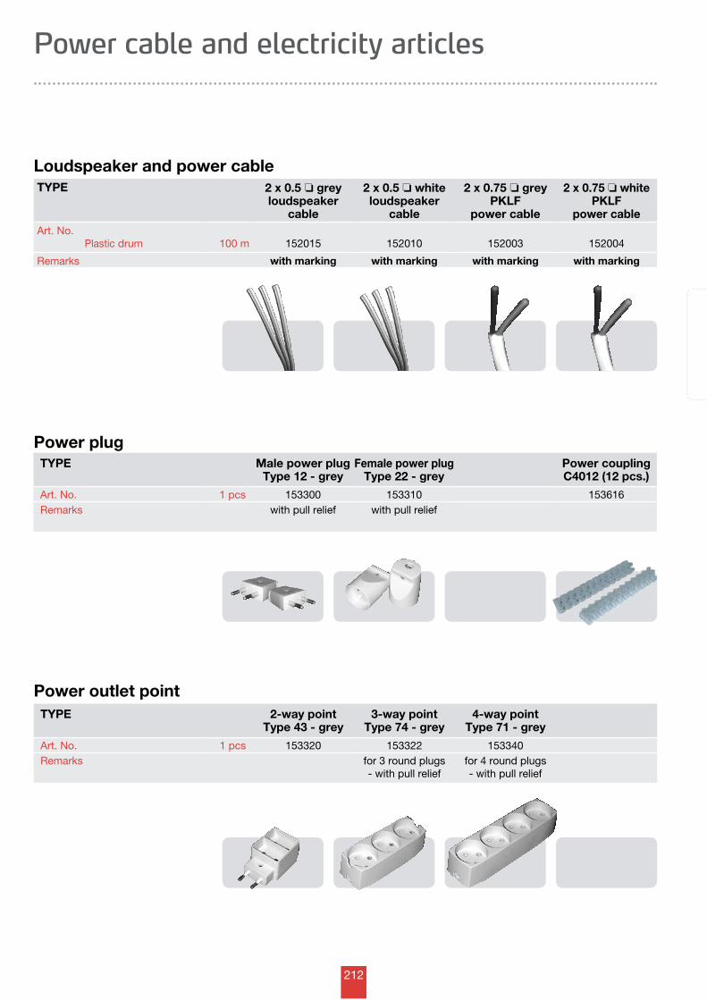
212
Power cable and electricity articles
Power plugTYPE Male power plug
Type 12 - greyFemale power plug
Type 22 - greyPower couplingC4012 (12 pcs.)
Art. No. 1 pcs 153300 153310 153616Remarks with pull relief with pull relief
Power outlet point
TYPE 2 x 0.5 o grey loudspeaker
cable
2 x 0.5 o white loudspeaker
cable
2 x 0.75 o grey PKLF
power cable
2 x 0.75 o white PKLF
power cableArt. No. Plastic drum 100 m 152015 152010 152003 152004
Remarks with marking with marking with marking with marking
Loudspeaker and power cable
TYPE 2-way pointType 43 - grey
3-way pointType 74 - grey
4-way pointType 71 - grey
Art. No. 1 pcs 153320 153322 153340Remarks for 3 round plugs
- with pull relieffor 4 round plugs- with pull relief
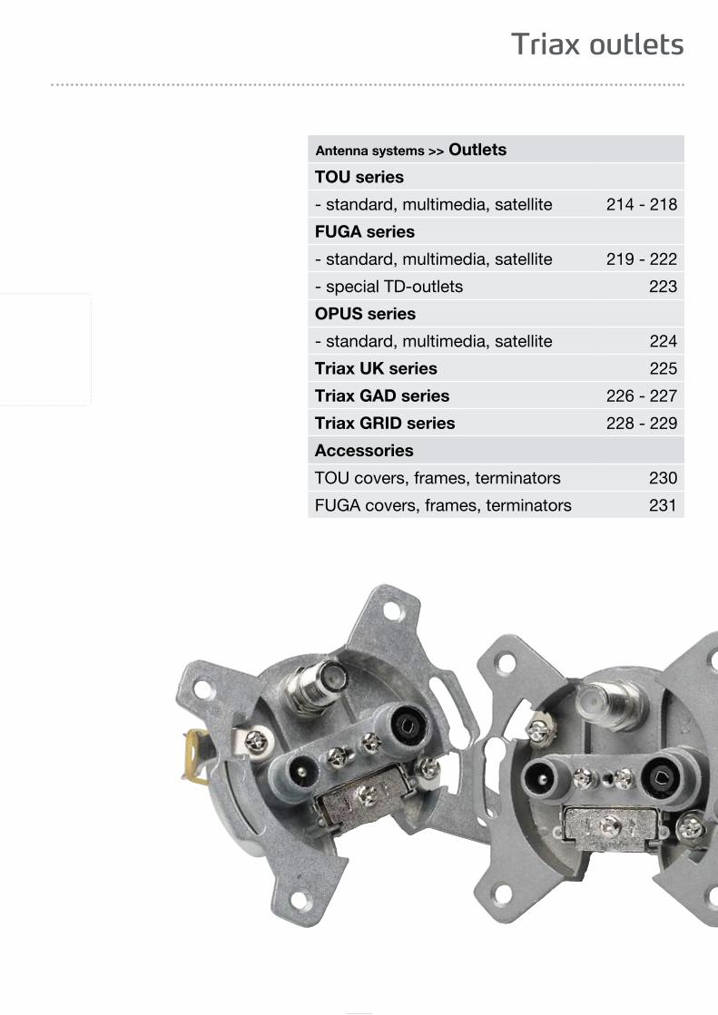
213
Triax outlets
Antenna systems >> Outlets
TOU series
- standard, multimedia, satellite 214 - 218
FUGA series
- standard, multimedia, satellite 219 - 222
- special TD-outlets 223
OPUS series
- standard, multimedia, satellite 224
Triax UK series 225
Triax GAD series 226 - 227
Triax GRID series 228 - 229
Accessories
TOU covers, frames, terminators 230
FUGA covers, frames, terminators 231
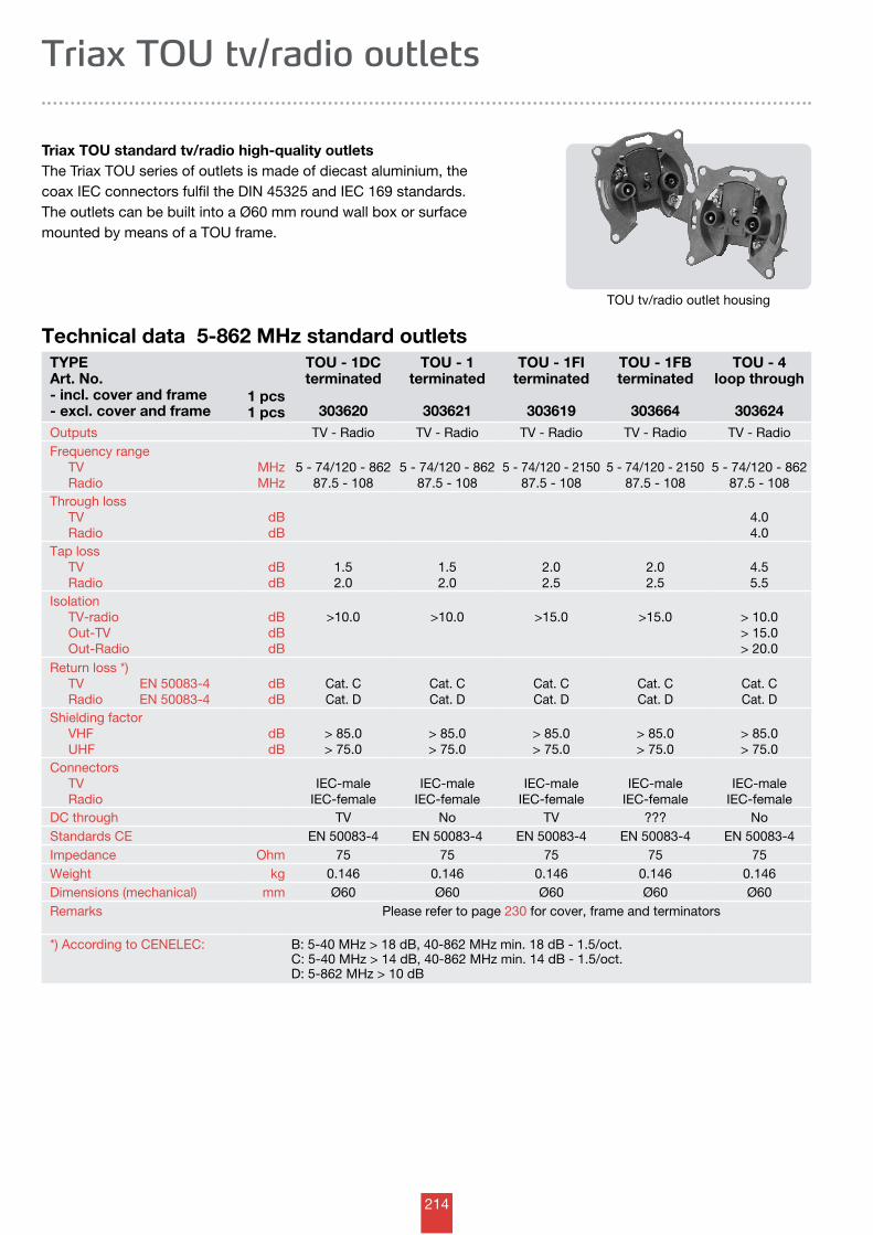
214
Technical data 5-862 MHz standard outlets
Triax TOU tv/radio outlets
TOU tv/radio outlet housing
Triax TOU standard tv/radio high-quality outlets The Triax TOU series of outlets is made of diecast aluminium, the coax IEC connectors fulfil the DIN 45325 and IEC 169 standards.The outlets can be built into a Ø60 mm round wall box or surface mounted by means of a TOU frame.
TYPEArt. No. - incl. cover and frame - excl. cover and frame
1 pcs1 pcs
TOU - 1DCterminated
303620
TOU - 1terminated
303621
TOU - 1FIterminated
303619
TOU - 1FBterminated
303664
TOU - 4loop through
303624Outputs TV - Radio TV - Radio TV - Radio TV - Radio TV - RadioFrequency range TV Radio
MHzMHz
5 - 74/120 - 86287.5 - 108
5 - 74/120 - 86287.5 - 108
5 - 74/120 - 215087.5 - 108
5 - 74/120 - 215087.5 - 108
5 - 74/120 - 86287.5 - 108
Through loss TV Radio
dBdB
4.04.0
Tap loss TV Radio
dBdB
1.52.0
1.52.0
2.02.5
2.02.5
4.55.5
Isolation TV-radio Out-TV Out-Radio
dBdBdB
>10.0 >10.0 >15.0 >15.0 > 10.0> 15.0> 20.0
Return loss *) TV EN 50083-4 Radio EN 50083-4
dBdB
Cat. CCat. D
Cat. CCat. D
Cat. CCat. D
Cat. CCat. D
Cat. CCat. D
Shielding factor VHF UHF
dBdB
> 85.0> 75.0
> 85.0> 75.0
> 85.0> 75.0
> 85.0> 75.0
> 85.0> 75.0
Connectors TV Radio
IEC-maleIEC-female
IEC-maleIEC-female
IEC-maleIEC-female
IEC-maleIEC-female
IEC-maleIEC-female
DC through TV No TV ??? NoStandards CE EN 50083-4 EN 50083-4 EN 50083-4 EN 50083-4 EN 50083-4Impedance Ohm 75 75 75 75 75Weight kg 0.146 0.146 0.146 0.146 0.146Dimensions (mechanical) mm Ø60 Ø60 Ø60 Ø60 Ø60Remarks Please refer to page 230 for cover, frame and terminators
*) According to CENELEC: B: 5-40 MHz > 18 dB, 40-862 MHz min. 18 dB - 1.5/oct.C: 5-40 MHz > 14 dB, 40-862 MHz min. 14 dB - 1.5/oct.D: 5-862 MHz > 10 dB
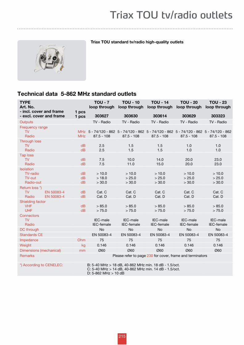
215
Triax TOU tv/radio outlets
Triax TOU standard tv/radio high-quality outlets
Technical data 5-862 MHz standard outletsTYPEArt. No. - incl. cover and frame - excl. cover and frame
1 pcs1 pcs
TOU - 7loop through
303627
TOU - 10loop through
303630
TOU - 14loop through
303614
TOU - 20loop through
303629
TOU - 23loop through
303323Outputs TV - Radio TV - Radio TV - Radio TV - Radio TV - RadioFrequency range TV Radio
MHzMHz
5 - 74/120 - 86287.5 - 108
5 - 74/120 - 86287.5 - 108
5 - 74/120 - 86287.5 - 108
5 - 74/120 - 86287.5 - 108
5 - 74/120 - 86287.5 - 108
Through loss TV Radio
dBdB
2.52.5
1.51.5
1.51.5
1.01.0
1.01.0
Tap loss TV Radio
dBdB
7.57.5
10.011.0
14.015.0
20.020.0
23.023.0
Isolation TV-radio TV-out Radio-out
dBdBdB
> 10.0> 18.0> 30.0
> 10.0> 25.0> 30.0
> 10.0> 25.0> 30.0
> 10.0> 25.0> 30.0
> 10.0> 25.0> 30.0
Return loss *) TV EN 50083-4 Radio EN 50083-4
dBdB
Cat. CCat. D
Cat. CCat. D
Cat. CCat. D
Cat. CCat. D
Cat. CCat. D
Shielding factor VHF UHF
dBdB
> 85.0> 75.0
> 85.0> 75.0
> 85.0> 75.0
> 85.0> 75.0
> 85.0> 75.0
Connectors TV Radio
IEC-maleIEC-female
IEC-maleIEC-female
IEC-maleIEC-female
IEC-maleIEC-female
IEC-maleIEC-female
DC through No No No No NoStandards CE EN 50083-4 EN 50083-4 EN 50083-4 EN 50083-4 EN 50083-4Impedance Ohm 75 75 75 75 75Weight kg 0.146 0.146 0.146 0.146 0.146Dimensions (mechanical) mm Ø60 Ø60 Ø60 Ø60 Ø60Remarks Please refer to page 230 for cover, frame and terminators
*) According to CENELEC: B: 5-40 MHz > 18 dB, 40-862 MHz min. 18 dB - 1.5/oct.C: 5-40 MHz > 14 dB, 40-862 MHz min. 14 dB - 1.5/oct.D: 5-862 MHz > 10 dB
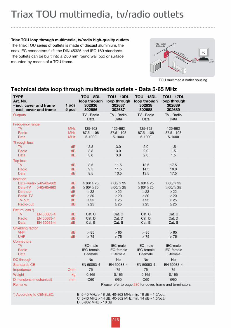
216
TOU - outletMultimedia
In
Out
65 - 1000 MHz
5 - 65 MHz
Data
PC
Technical data loop through multimedia outlets - Data 5-65 MHzTYPEArt. No. - incl. cover and frame - excl. cover and frame
1 pcs5 pcs
TOU - 8DLloop through
302636302686
TOU - 10DLloop through
302637302687
TOU - 13DLloop through
302638302688
TOU - 17DLloop through
302639302689
Outputs TV - RadioData
TV - RadioData
TV - RadioData
TV - RadioData
Frequency range TV Radio Data
MHzMHzMHz
125-86287.5 - 108
5-1000
125-86287.5 - 108
5-1000
125-86287.5 - 108
5-1000
125-86287.5 - 108
5-1000
Through loss TV Radio Data
dBdBdB
3.83.83.8
3.03.03.0
2.02.02.0
1.51.51.5
Tap loss TV Radio Data
dBdBdB
8.59.58.5
11.511.510.5
13.514.513.5
17.518.017.5
Isolation Data-Radio 5-65/65/862 Data-TV 5-65/65/862 Data out Radio-TV TV-out Radio-out
dBdBdBdBdBdB
≥ 60/ ≥ 25≥ 60/ ≥ 25
≥ 22≥ 20≥ 25≥ 25
≥ 60/ ≥ 25≥ 60/ ≥ 25
≥ 22≥ 20≥ 25≥ 25
≥ 60/ ≥ 25≥ 60/ ≥ 25
≥ 22≥ 20≥ 25≥ 25
≥ 60/ ≥ 25≥ 60/ ≥ 25
≥ 22≥ 20≥ 25≥ 25
Return loss *) TV EN 50083-4 Radio EN 50083-4 Data EN 50083-4
dBdBdB
Cat. CCat. DCat. B
Cat. CCat. DCat. B
Cat. CCat. DCat. B
Cat. CCat. DCat. B
Shielding factor VHF UHF
dBdB
> 85> 75
> 85> 75
> 85> 75
> 85> 75
Connectors TV Radio Data
IEC-maleIEC-femaleF-female
IEC-maleIEC-femaleF-female
IEC-maleIEC-femaleF-female
IEC-maleIEC-femaleF-female
DC through No No No NoStandards CE EN 50083-4 EN 50083-4 EN 50083-4 EN 50083-4Impedance Ohm 75 75 75 75Weight kg 0.165 0.165 0.165 0.165Dimensions (mechanical) mm Ø60 Ø60 Ø60 Ø60Remarks Please refer to page 230 for cover, frame and terminators
*) According to CENELEC: B: 5-40 MHz > 18 dB, 40-862 MHz min. 18 dB - 1.5/oct.C: 5-40 MHz > 14 dB, 40-862 MHz min. 14 dB - 1.5/oct.D: 5-862 MHz > 10 dB
Triax TOU multimedia, tv/radio outlets
Triax TOU loop through multimedia, tv/radio high-quality outlets The Triax TOU series of outlets is made of diecast aluminium, the coax IEC connectors fulfil the DIN 45325 and IEC 169 standards.The outlets can be built into a Ø60 mm round wall box or surface mounted by means of a TOU frame.
TOU multimedia outlet housing
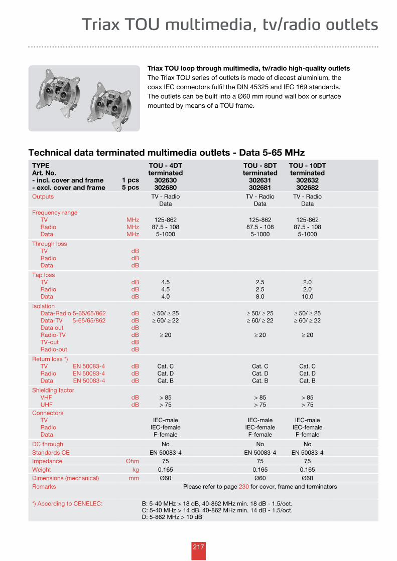
217
Triax TOU multimedia, tv/radio outlets
Triax TOU loop through multimedia, tv/radio high-quality outlets The Triax TOU series of outlets is made of diecast aluminium, the coax IEC connectors fulfil the DIN 45325 and IEC 169 standards.The outlets can be built into a Ø60 mm round wall box or surface mounted by means of a TOU frame.
Technical data terminated multimedia outlets - Data 5-65 MHzTYPEArt. No. - incl. cover and frame - excl. cover and frame
1 pcs5 pcs
TOU - 4DTterminated
302630302680
TOU - 8DTterminated
302631302681
TOU - 10DTterminated
302632302682
Outputs TV - RadioData
TV - RadioData
TV - RadioData
Frequency range TV Radio Data
MHzMHzMHz
125-86287.5 - 108
5-1000
125-86287.5 - 108
5-1000
125-86287.5 - 108
5-1000
Through loss TV Radio Data
dBdBdB
Tap loss TV Radio Data
dBdBdB
4.54.54.0
2.52.58.0
2.02.0
10.0
Isolation Data-Radio 5-65/65/862 Data-TV 5-65/65/862 Data out Radio-TV TV-out Radio-out
dBdBdBdBdBdB
≥ 50/ ≥ 25≥ 60/ ≥ 22
≥ 20
≥ 50/ ≥ 25≥ 60/ ≥ 22
≥ 20
≥ 50/ ≥ 25≥ 60/ ≥ 22
≥ 20
Return loss *) TV EN 50083-4 Radio EN 50083-4 Data EN 50083-4
dBdBdB
Cat. CCat. DCat. B
Cat. CCat. DCat. B
Cat. CCat. DCat. B
Shielding factor VHF UHF
dBdB
> 85> 75
> 85> 75
> 85> 75
Connectors TV Radio Data
IEC-maleIEC-femaleF-female
IEC-maleIEC-femaleF-female
IEC-maleIEC-femaleF-female
DC through No No NoStandards CE EN 50083-4 EN 50083-4 EN 50083-4Impedance Ohm 75 75 75Weight kg 0.165 0.165 0.165Dimensions (mechanical) mm Ø60 Ø60 Ø60Remarks Please refer to page 230 for cover, frame and terminators
*) According to CENELEC: B: 5-40 MHz > 18 dB, 40-862 MHz min. 18 dB - 1.5/oct.C: 5-40 MHz > 14 dB, 40-862 MHz min. 14 dB - 1.5/oct.D: 5-862 MHz > 10 dB
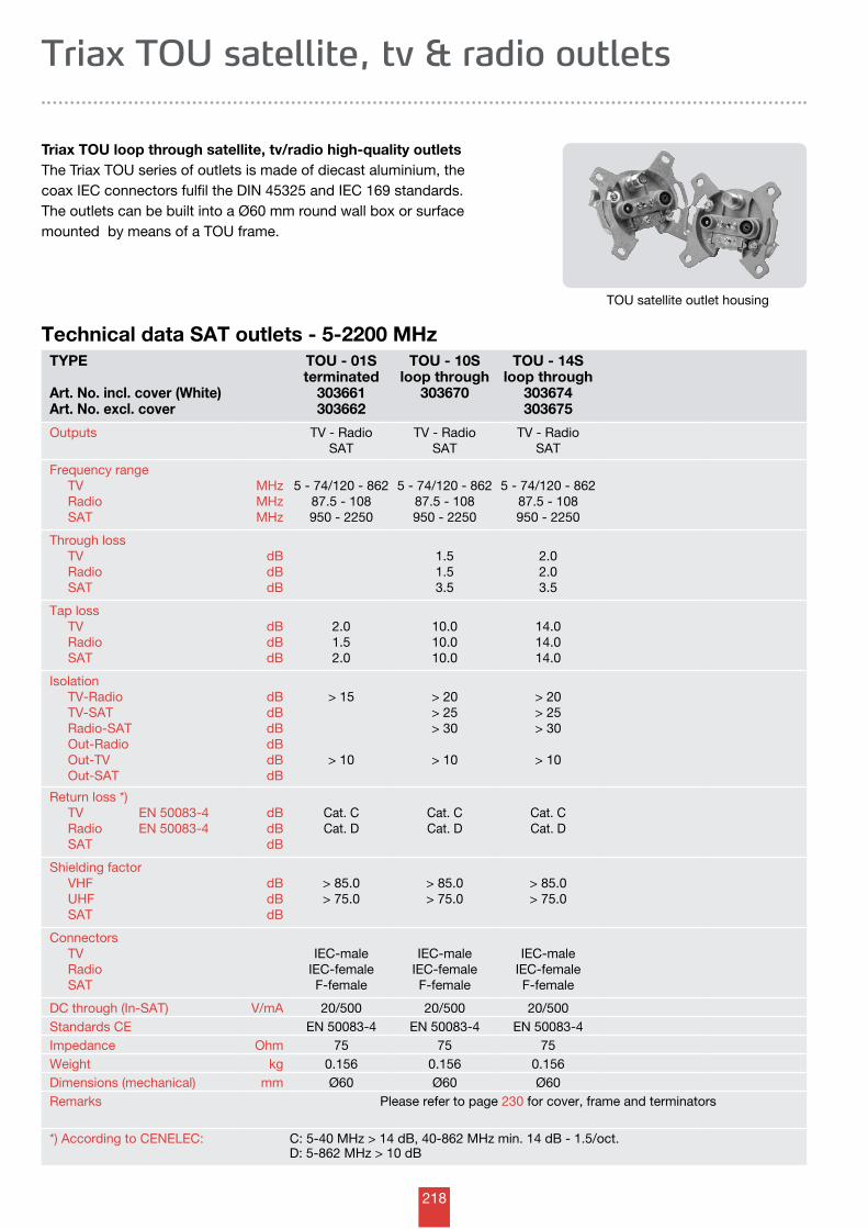
218
TYPE
Art. No. incl. cover (White)Art. No. excl. cover
TOU - 01Sterminated
303661303662
TOU - 10Sloop through
303670
TOU - 14Sloop through
303674303675
Outputs TV - RadioSAT
TV - RadioSAT
TV - RadioSAT
Frequency range TV Radio SAT
MHzMHzMHz
5 - 74/120 - 86287.5 - 108950 - 2250
5 - 74/120 - 86287.5 - 108950 - 2250
5 - 74/120 - 86287.5 - 108950 - 2250
Through loss TV Radio SAT
dBdBdB
1.51.53.5
2.02.03.5
Tap loss TV Radio SAT
dBdBdB
2.01.52.0
10.010.010.0
14.014.014.0
Isolation TV-Radio TV-SAT Radio-SAT Out-Radio Out-TV Out-SAT
dBdBdBdBdBdB
> 15
> 10
> 20> 25> 30
> 10
> 20> 25> 30
> 10
Return loss *) TV EN 50083-4 Radio EN 50083-4 SAT
dBdBdB
Cat. CCat. D
Cat. CCat. D
Cat. CCat. D
Shielding factor VHF UHF SAT
dBdBdB
> 85.0> 75.0
> 85.0> 75.0
> 85.0> 75.0
Connectors TV Radio SAT
IEC-maleIEC-femaleF-female
IEC-maleIEC-femaleF-female
IEC-maleIEC-femaleF-female
DC through (In-SAT) V/mA 20/500 20/500 20/500Standards CE EN 50083-4 EN 50083-4 EN 50083-4Impedance Ohm 75 75 75Weight kg 0.156 0.156 0.156Dimensions (mechanical) mm Ø60 Ø60 Ø60Remarks Please refer to page 230 for cover, frame and terminators
*) According to CENELEC: C: 5-40 MHz > 14 dB, 40-862 MHz min. 14 dB - 1.5/oct.D: 5-862 MHz > 10 dB
Technical data SAT outlets - 5-2200 MHz
Triax TOU satellite, tv & radio outlets
Triax TOU loop through satellite, tv/radio high-quality outlets The Triax TOU series of outlets is made of diecast aluminium, the coax IEC connectors fulfil the DIN 45325 and IEC 169 standards.The outlets can be built into a Ø60 mm round wall box or surface mounted by means of a TOU frame.
TOU satellite outlet housing
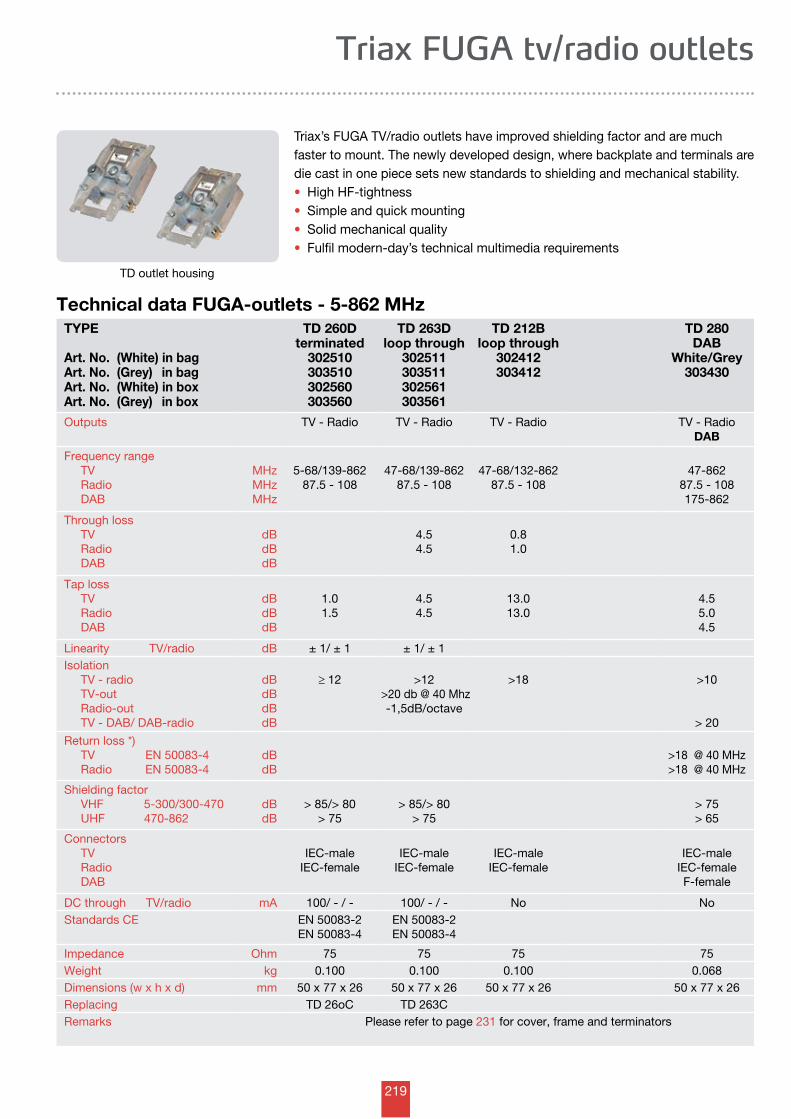
219
Triax FUGA tv/radio outlets
Triax’s FUGA TV/radio outlets have improved shielding factor and are much faster to mount. The newly developed design, where backplate and terminals are die cast in one piece sets new standards to shielding and mechanical stability.• High HF-tightness• Simple and quick mounting• Solid mechanical quality• Fulfil modern-day’s technical multimedia requirements
Technical data FUGA-outlets - 5-862 MHzTYPE
Art. No. (White) in bagArt. No. (Grey) in bagArt. No. (White) in boxArt. No. (Grey) in box
TD 260Dterminated
302510303510302560303560
TD 263Dloop through
302511303511302561303561
TD 212Bloop through
302412303412
TD 280DAB
White/Grey303430
Outputs TV - Radio TV - Radio TV - Radio TV - RadioDAB
Frequency range TV Radio DAB
MHzMHzMHz
5-68/139-86287.5 - 108
47-68/139-86287.5 - 108
47-68/132-86287.5 - 108
47-86287.5 - 108175-862
Through loss TV Radio DAB
dBdBdB
4.54.5
0.81.0
Tap loss TV Radio DAB
dBdBdB
1.01.5
4.54.5
13.013.0
4.55.04.5
Linearity TV/radio dB ± 1/ ± 1 ± 1/ ± 1Isolation TV - radio TV-out Radio-out TV - DAB/ DAB-radio
dBdBdBdB
≥ 12 >12 >20 db @ 40 Mhz
-1,5dB/octave
>18
>10
> 20
Return loss *) TV EN 50083-4 Radio EN 50083-4
dBdB
>18 @ 40 MHz>18 @ 40 MHz
Shielding factor VHF 5-300/300-470 UHF 470-862
dBdB
> 85/> 80> 75
> 85/> 80> 75
> 75> 65
Connectors TV Radio DAB
IEC-maleIEC-female
IEC-maleIEC-female
IEC-maleIEC-female
IEC-maleIEC-femaleF-female
DC through TV/radio mA 100/ - / - 100/ - / - No NoStandards CE EN 50083-2
EN 50083-4EN 50083-2EN 50083-4
Impedance Ohm 75 75 75 75Weight kg 0.100 0.100 0.100 0.068Dimensions (w x h x d) mm 50 x 77 x 26 50 x 77 x 26 50 x 77 x 26 50 x 77 x 26Replacing TD 26oC TD 263CRemarks Please refer to page 231 for cover, frame and terminators
TD outlet housing
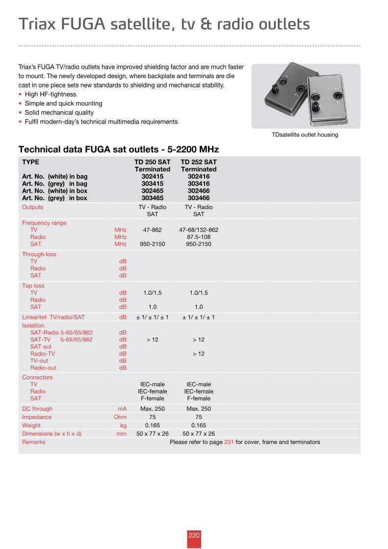
220
Technical data FUGA sat outlets - 5-2200 MHz
Triax FUGA satellite, tv & radio outlets
Triax’s FUGA TV/radio outlets have improved shielding factor and are much faster to mount. The newly developed design, where backplate and terminals are die cast in one piece sets new standards to shielding and mechanical stability.• High HF-tightness• Simple and quick mounting• Solid mechanical quality• Fulfil modern-day’s technical multimedia requirements
TYPE
Art. No. (white) in bagArt. No. (grey) in bagArt. No. (white) in boxArt. No. (grey) in box
TD 250 SATTerminated
302415303415302465303465
TD 252 SATTerminated
302416303416302466303466
Outputs TV - RadioSAT
TV - RadioSAT
Frequency range TV Radio SAT
MHzMHzMHz
47-862
950-2150
47-68/132-86287.5-108950-2150
Through loss TV Radio SAT
dBdBdB
Tap loss TV Radio SAT
dBdBdB
1.0/1.5
1.0
1.0/1.5
1.0
Linearitet TV/radio/SAT dB ± 1/ ± 1/ ± 1 ± 1/ ± 1/ ± 1Isolation SAT-Radio 5-65/65/862 SAT-TV 5-65/65/862 SAT out Radio-TV TV-out Radio-out
dBdBdBdBdBdB
> 12 > 12
> 12
Connectors TV Radio SAT
IEC-maleIEC-femaleF-female
IEC-maleIEC-femaleF-female
DC through mA Max. 250 Max. 250Impedance Ohm 75 75Weight kg 0.165 0.165Dimensions (w x h x d) mm 50 x 77 x 26 50 x 77 x 26Remarks Please refer to page 231 for cover, frame and terminators
TDsatellite outlet housing
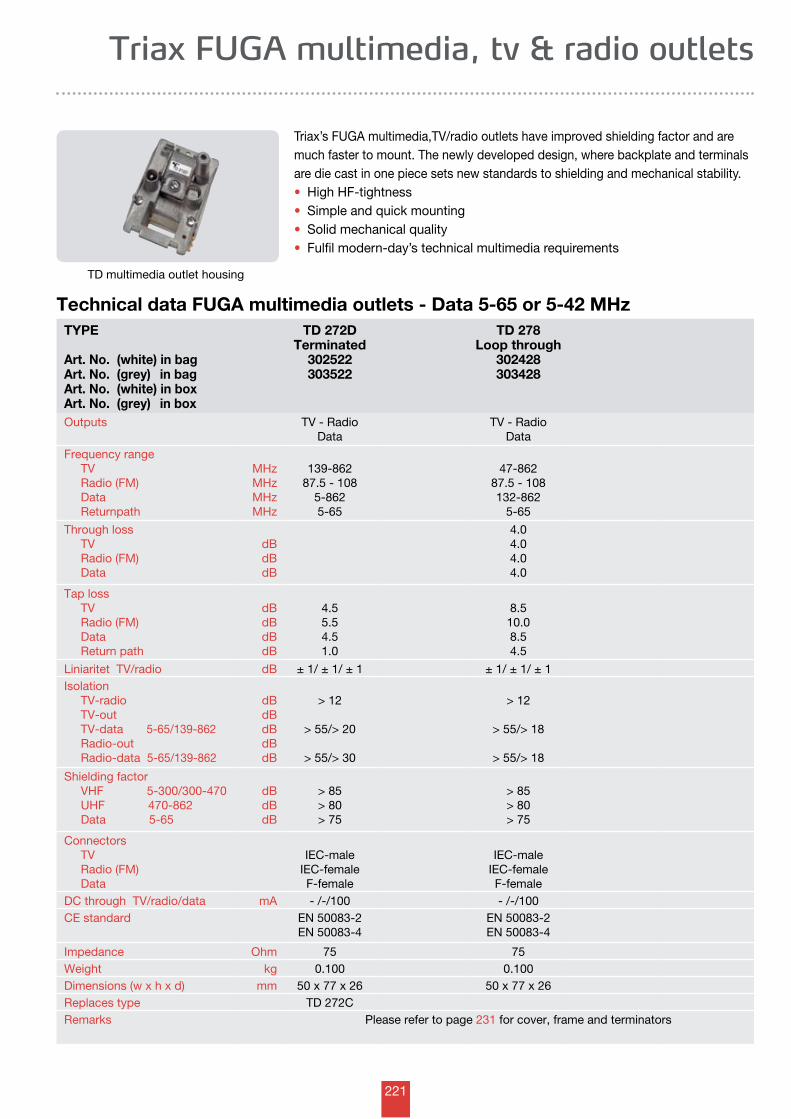
221
Triax FUGA multimedia, tv & radio outlets
Triax’s FUGA multimedia,TV/radio outlets have improved shielding factor and are much faster to mount. The newly developed design, where backplate and terminals are die cast in one piece sets new standards to shielding and mechanical stability.• High HF-tightness• Simple and quick mounting• Solid mechanical quality• Fulfil modern-day’s technical multimedia requirements
Technical data FUGA multimedia outlets - Data 5-65 or 5-42 MHzTYPE
Art. No. (white) in bagArt. No. (grey) in bagArt. No. (white) in boxArt. No. (grey) in box
TD 272DTerminated
302522303522
TD 278Loop through
302428303428
Outputs TV - RadioData
TV - RadioData
Frequency range TV Radio (FM) Data Returnpath
MHzMHzMHzMHz
139-86287.5 - 108
5-8625-65
47-86287.5 - 108132-862
5-65
Through loss TV Radio (FM) Data
dBdBdB
4.04.04.04.0
Tap loss TV Radio (FM) Data Return path
dBdBdBdB
4.55.54.51.0
8.510.08.54.5
Liniaritet TV/radio dB ± 1/ ± 1/ ± 1 ± 1/ ± 1/ ± 1Isolation TV-radio TV-out TV-data 5-65/139-862 Radio-out Radio-data 5-65/139-862
dBdBdBdBdB
> 12
> 55/> 20
> 55/> 30
> 12
> 55/> 18
> 55/> 18
Shielding factor VHF 5-300/300-470 UHF 470-862 Data 5-65
dBdBdB
> 85> 80> 75
> 85> 80> 75
Connectors TV Radio (FM) Data
IEC-maleIEC-femaleF-female
IEC-maleIEC-femaleF-female
DC through TV/radio/data mA - /-/100 - /-/100CE standard EN 50083-2
EN 50083-4EN 50083-2EN 50083-4
Impedance Ohm 75 75Weight kg 0.100 0.100Dimensions (w x h x d) mm 50 x 77 x 26 50 x 77 x 26Replaces type TD 272CRemarks Please refer to page 231 for cover, frame and terminators
TD multimedia outlet housing
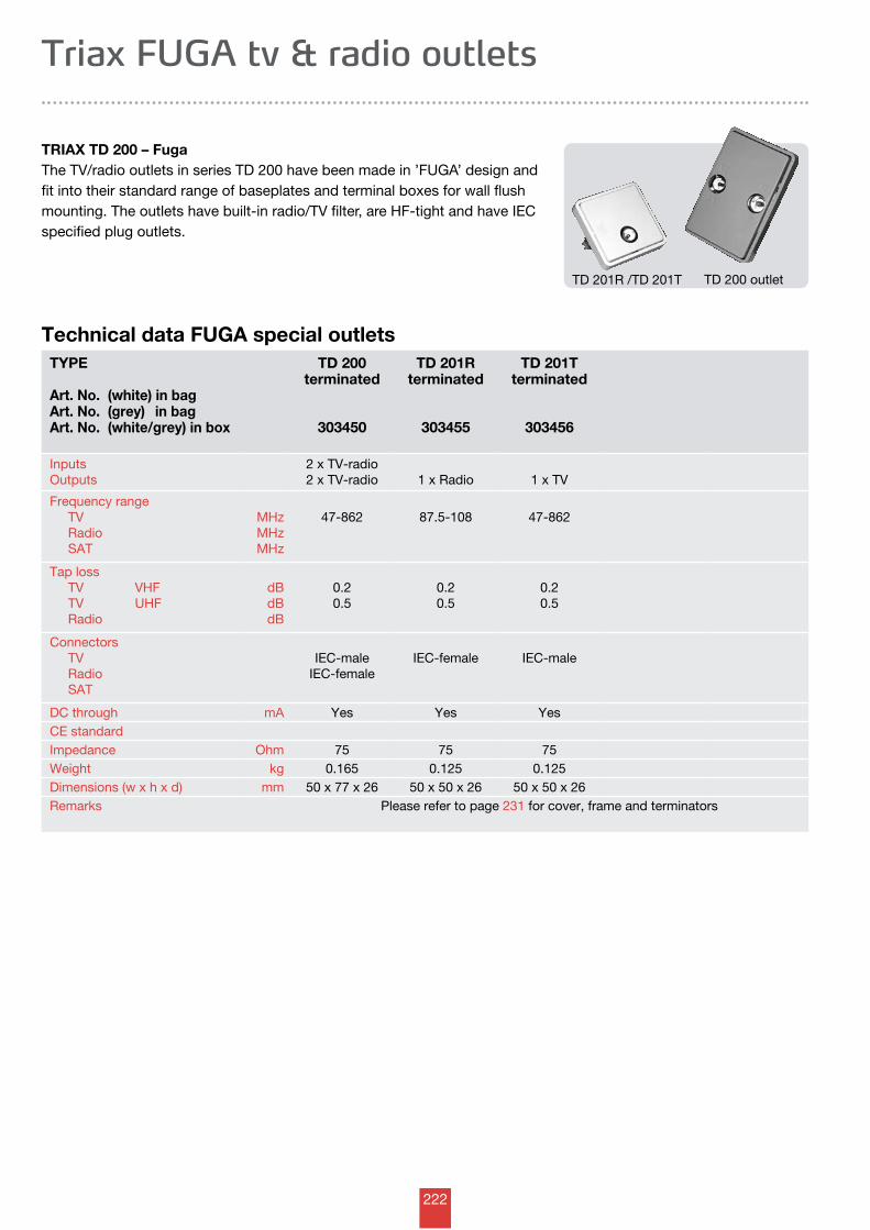
222
Technical data FUGA special outlets
Triax FUGA tv & radio outlets
TRIAX TD 200 – FugaThe TV/radio outlets in series TD 200 have been made in ’FUGA’ design and fit into their standard range of baseplates and terminal boxes for wall flush mounting. The outlets have built-in radio/TV filter, are HF-tight and have IEC specified plug outlets.
TYPE
Art. No. (white) in bagArt. No. (grey) in bagArt. No. (white/grey) in box
TD 200terminated
303450
TD 201Rterminated
303455
TD 201Tterminated
303456
InputsOutputs
2 x TV-radio2 x TV-radio 1 x Radio 1 x TV
Frequency range TV Radio SAT
MHzMHzMHz
47-862 87.5-108 47-862
Tap loss TV VHF TV UHF Radio
dBdBdB
0.20.5
0.20.5
0.20.5
Connectors TV Radio SAT
IEC-maleIEC-female
IEC-female IEC-male
DC through mA Yes Yes YesCE standardImpedance Ohm 75 75 75Weight kg 0.165 0.125 0.125Dimensions (w x h x d) mm 50 x 77 x 26 50 x 50 x 26 50 x 50 x 26Remarks Please refer to page 231 for cover, frame and terminators
TD 200 outletTD 201R /TD 201T
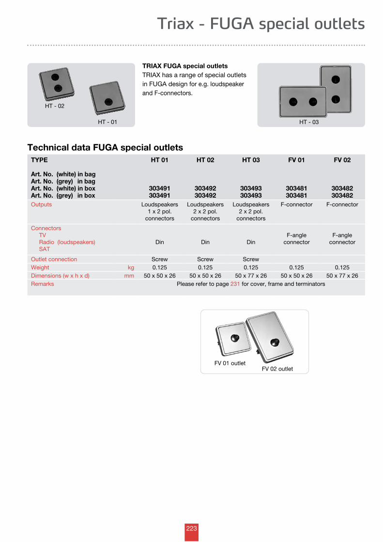
223
Triax - FUGA special outlets
TRIAX FUGA special outletsTRIAX has a range of special outlets in FUGA design for e.g. loudspeaker and F-connectors.
Technical data FUGA special outletsTYPE
Art. No. (white) in bagArt. No. (grey) in bagArt. No. (white) in boxArt. No. (grey) in box
HT 01
303491303491
HT 02
303492303492
HT 03
303493303493
FV 01
303481303481
FV 02
303482303482
Outputs Loudspeakers1 x 2 pol.
connectors
Loudspeakers2 x 2 pol.
connectors
Loudspeakers2 x 2 pol.
connectors
F-connector F-connector
Connectors TV Radio (loudspeakers) SAT
Din Din Din F-angle
connector F-angle
connector
Outlet connection Screw Screw ScrewWeight kg 0.125 0.125 0.125 0.125 0.125Dimensions (w x h x d) mm 50 x 50 x 26 50 x 50 x 26 50 x 77 x 26 50 x 50 x 26 50 x 77 x 26Remarks Please refer to page 231 for cover, frame and terminators
FV 02 outletFV 01 outlet
HT - 02
HT - 01 HT - 03
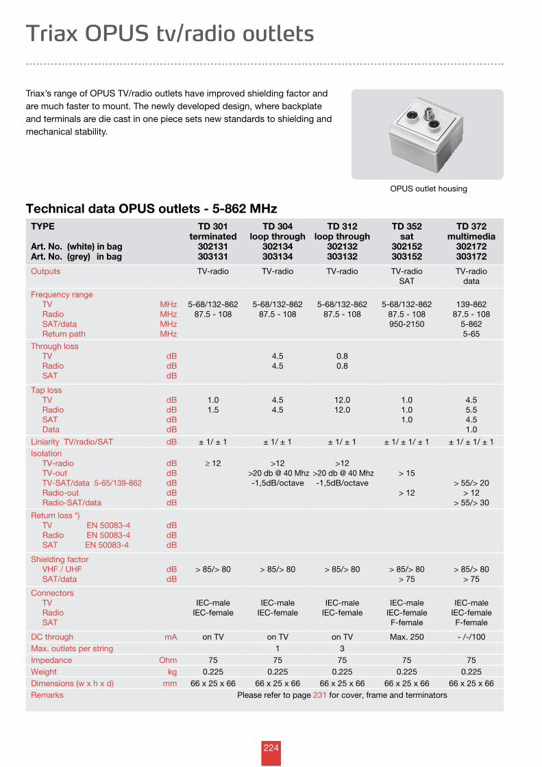
224
Triax OPUS tv/radio outlets
Triax’s range of OPUS TV/radio outlets have improved shielding factor and are much faster to mount. The newly developed design, where backplate and terminals are die cast in one piece sets new standards to shielding and mechanical stability.
Technical data OPUS outlets - 5-862 MHz
OPUS outlet housing
TYPE
Art. No. (white) in bagArt. No. (grey) in bag
TD 301terminated
302131303131
TD 304loop through
302134303134
TD 312loop through
302132303132
TD 352 sat
302152303152
TD 372multimedia
302172303172
Outputs TV-radio TV-radio TV-radio TV-radioSAT
TV-radiodata
Frequency range TV Radio SAT/data Return path
MHzMHzMHzMHz
5-68/132-86287.5 - 108
5-68/132-86287.5 - 108
5-68/132-86287.5 - 108
5-68/132-86287.5 - 108950-2150
139-86287.5 - 108
5-8625-65
Through loss TV Radio SAT
dBdBdB
4.54.5
0.80.8
Tap loss TV Radio SAT Data
dBdBdBdB
1.01.5
4.54.5
12.012.0
1.01.01.0
4.55.54.51.0
Liniarity TV/radio/SAT dB ± 1/ ± 1 ± 1/ ± 1 ± 1/ ± 1 ± 1/ ± 1/ ± 1 ± 1/ ± 1/ ± 1Isolation TV-radio TV-out TV-SAT/data 5-65/139-862 Radio-out Radio-SAT/data
dBdBdBdBdB
≥ 12 >12 >20 db @ 40 Mhz
-1,5dB/octave
>12 >20 db @ 40 Mhz
-1,5dB/octave> 15
> 12> 55/> 20
> 12> 55/> 30
Return loss *) TV EN 50083-4 Radio EN 50083-4 SAT EN 50083-4
dBdBdB
Shielding factor VHF / UHF SAT/data
dBdB
> 85/> 80 > 85/> 80 > 85/> 80 > 85/> 80> 75
> 85/> 80> 75
Connectors TV Radio SAT
IEC-maleIEC-female
IEC-maleIEC-female
IEC-maleIEC-female
IEC-maleIEC-femaleF-female
IEC-maleIEC-femaleF-female
DC through mA on TV on TV on TV Max. 250 - /-/100Max. outlets per string 1 3Impedance Ohm 75 75 75 75 75Weight kg 0.225 0.225 0.225 0.225 0.225Dimensions (w x h x d) mm 66 x 25 x 66 66 x 25 x 66 66 x 25 x 66 66 x 25 x 66 66 x 25 x 66Remarks Please refer to page 231 for cover, frame and terminators
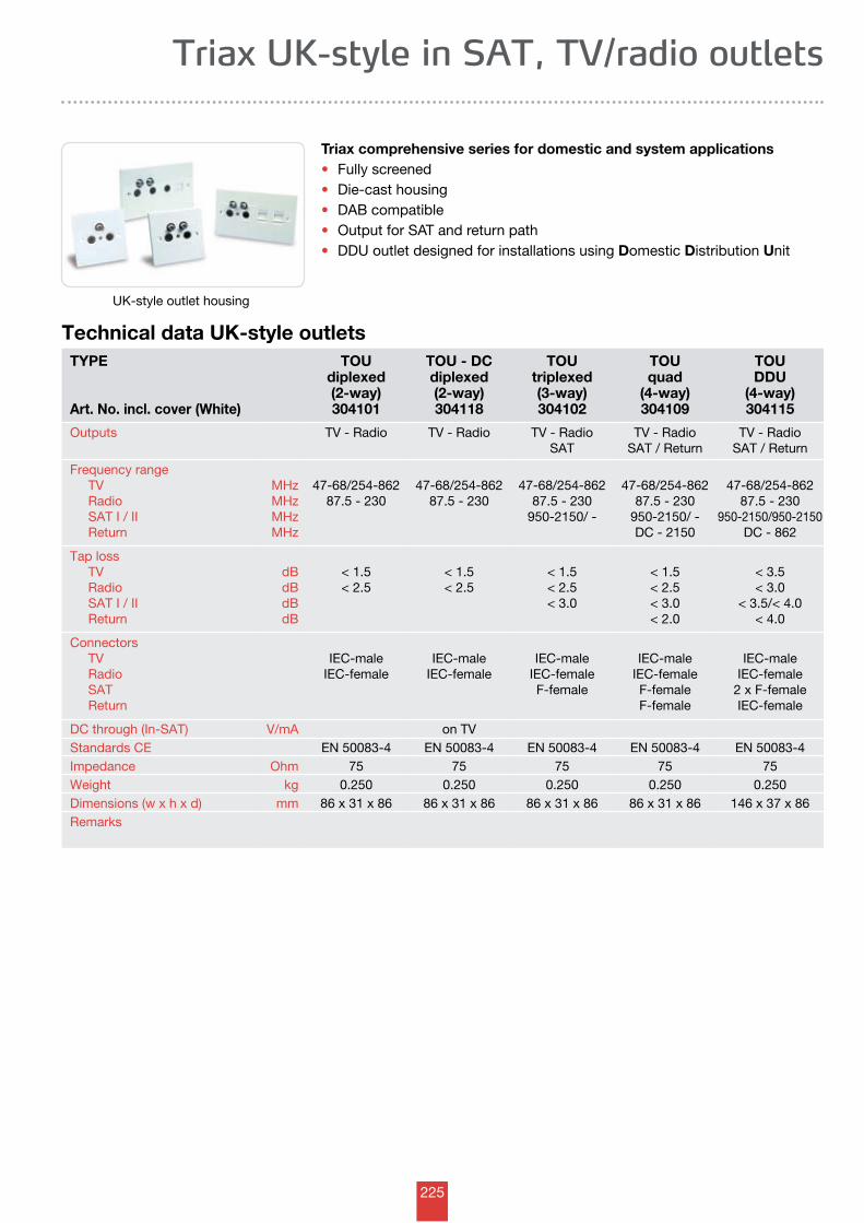
225
Technical data UK-style outletsTYPE
Art. No. incl. cover (White)
TOUdiplexed(2-way)304101
TOU - DCdiplexed(2-way)304118
TOU triplexed(3-way)304102
TOU quad
(4-way)304109
TOU DDU
(4-way)304115
Outputs TV - Radio TV - Radio TV - RadioSAT
TV - RadioSAT / Return
TV - RadioSAT / Return
Frequency range TV Radio SAT I / II Return
MHzMHzMHzMHz
47-68/254-86287.5 - 230
47-68/254-86287.5 - 230
47-68/254-86287.5 - 230
950-2150/ -
47-68/254-86287.5 - 230
950-2150/ -DC - 2150
47-68/254-86287.5 - 230
950-2150/950-2150DC - 862
Tap loss TV Radio SAT I / II Return
dBdBdBdB
< 1.5< 2.5
< 1.5< 2.5
< 1.5< 2.5< 3.0
< 1.5< 2.5< 3.0< 2.0
< 3.5< 3.0
< 3.5/< 4.0< 4.0
Connectors TV Radio SAT Return
IEC-maleIEC-female
IEC-maleIEC-female
IEC-maleIEC-femaleF-female
IEC-maleIEC-femaleF-femaleF-female
IEC-maleIEC-female
2 x F-femaleIEC-female
DC through (In-SAT) V/mA on TVStandards CE EN 50083-4 EN 50083-4 EN 50083-4 EN 50083-4 EN 50083-4Impedance Ohm 75 75 75 75 75Weight kg 0.250 0.250 0.250 0.250 0.250Dimensions (w x h x d) mm 86 x 31 x 86 86 x 31 x 86 86 x 31 x 86 86 x 31 x 86 146 x 37 x 86Remarks
Triax UK-style in SAT, TV/radio outlets
Triax comprehensive series for domestic and system applications • Fully screened• Die-cast housing• DAB compatible• Output for SAT and return path• DDU outlet designed for installations using Domestic Distribution Unit
UK-style outlet housing
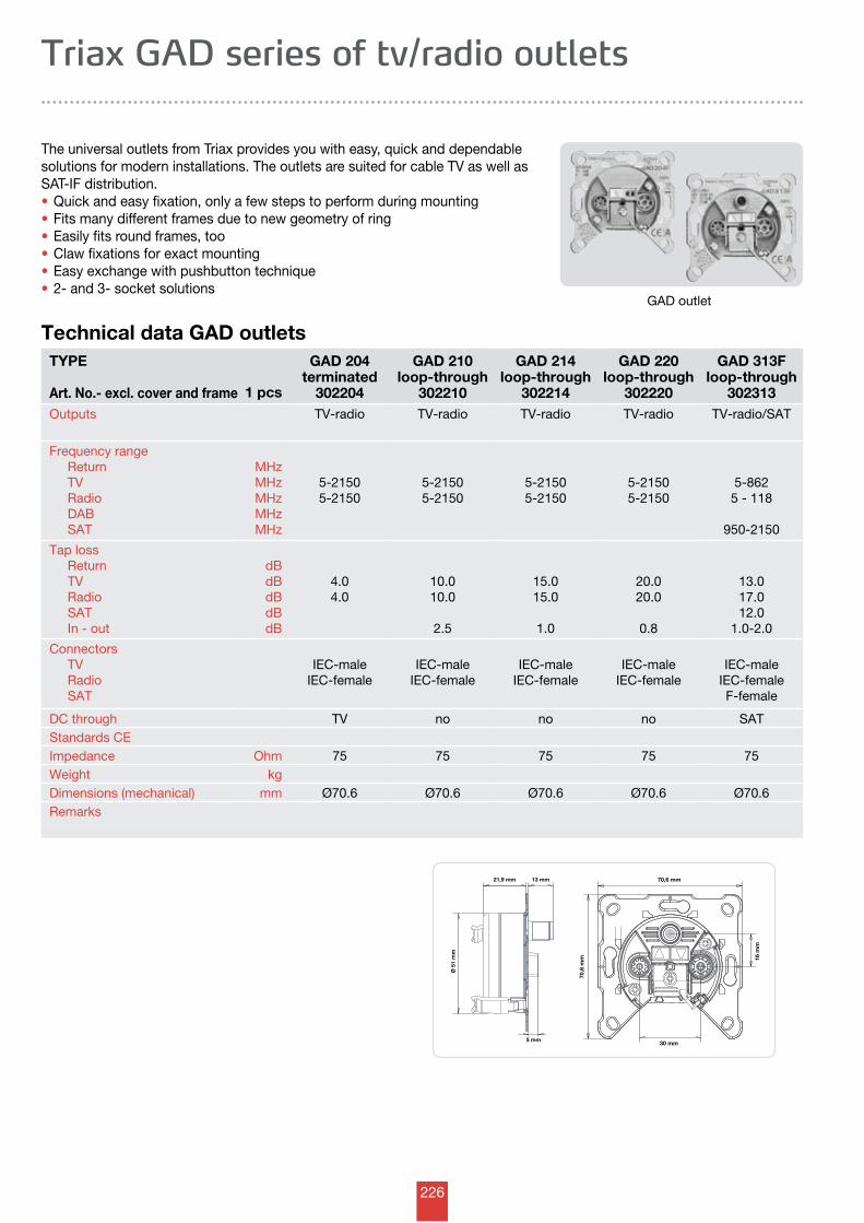
226
70,6 mm
30 mm
70,6
mm 16
mm
21,9 mm
Ø 5
1 m
m
13 mm
5 mm
Triax GAD series of tv/radio outlets
GAD outlet
The universal outlets from Triax provides you with easy, quick and dependablesolutions for modern installations. The outlets are suited for cable TV as well as SAT-IF distribution. •Quick and easy fixation, only a few steps to perform during mounting•Fits many different frames due to new geometry of ring•Easily fits round frames, too•Claw fixations for exact mounting•Easy exchange with pushbutton technique•2- and 3- socket solutions
Technical data GAD outletsTYPE Art. No.- excl. cover and frame 1 pcs
GAD 204terminated
302204
GAD 210loop-through
302210
GAD 214loop-through
302214
GAD 220loop-through
302220
GAD 313Floop-through
302313Outputs TV-radio TV-radio TV-radio TV-radio TV-radio/SAT
Frequency range Return TV Radio DAB SAT
MHzMHzMHzMHzMHz
5-21505-2150
5-21505-2150
5-21505-2150
5-21505-2150
5-8625 - 118
950-2150
Tap loss Return TV Radio SAT In - out
dBdBdBdBdB
4.04.0
10.010.0
2.5
15.015.0
1.0
20.020.0
0.8
13.017.012.0
1.0-2.0
Connectors TV Radio SAT
IEC-maleIEC-female
IEC-maleIEC-female
IEC-maleIEC-female
IEC-maleIEC-female
IEC-maleIEC-femaleF-female
DC through TV no no no SATStandards CEImpedance Ohm 75 75 75 75 75Weight kgDimensions (mechanical) mm Ø70.6 Ø70.6 Ø70.6 Ø70.6 Ø70.6Remarks
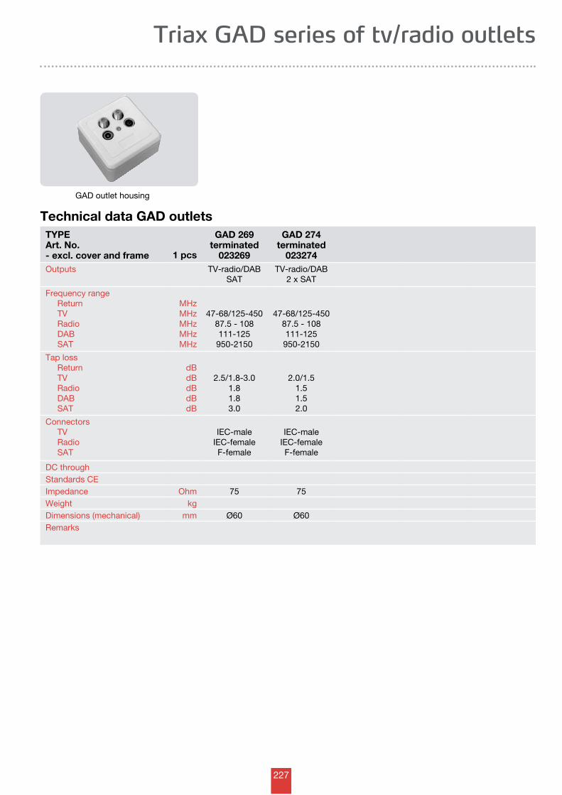
227
Technical data GAD outletsTYPEArt. No. - excl. cover and frame 1 pcs
GAD 269terminated
023269
GAD 274terminated
023274Outputs TV-radio/DAB
SATTV-radio/DAB
2 x SAT
Frequency range Return TV Radio DAB SAT
MHzMHzMHzMHzMHz
47-68/125-45087.5 - 108111-125950-2150
47-68/125-45087.5 - 108111-125
950-2150
Tap loss Return TV Radio DAB SAT
dBdBdBdBdB
2.5/1.8-3.01.81.83.0
2.0/1.51.51.52.0
Connectors TV Radio SAT
IEC-maleIEC-femaleF-female
IEC-maleIEC-femaleF-female
DC throughStandards CEImpedance Ohm 75 75Weight kgDimensions (mechanical) mm Ø60 Ø60Remarks
Triax GAD series of tv/radio outlets
GAD outlet housing
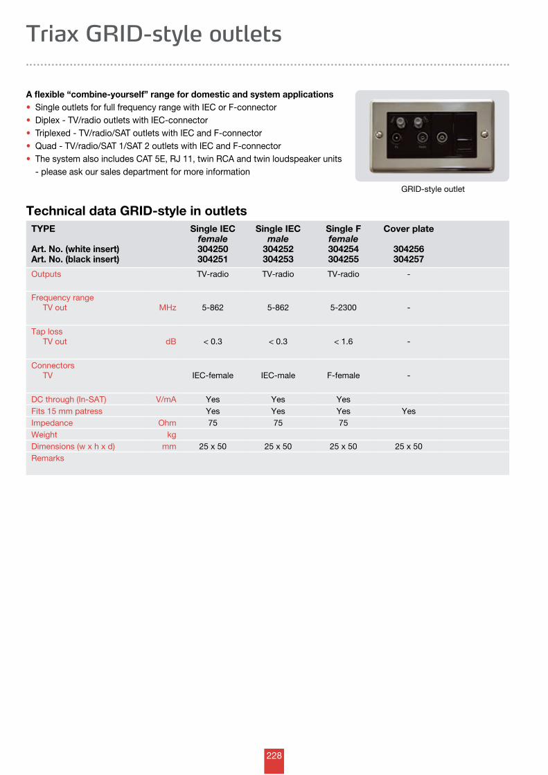
228
Technical data GRID-style in outlets
Triax GRID-style outlets
A flexible “combine-yourself” range for domestic and system applications • Single outlets for full frequency range with IEC or F-connector• Diplex - TV/radio outlets with IEC-connector• Triplexed - TV/radio/SAT outlets with IEC and F-connector• Quad - TV/radio/SAT 1/SAT 2 outlets with IEC and F-connector • The system also includes CAT 5E, RJ 11, twin RCA and twin loudspeaker units - please ask our sales department for more information
GRID-style outlet
TYPE
Art. No. (white insert)Art. No. (black insert)
Single IECfemale304250304251
Single IECmale
304252304253
Single Ffemale304254304255
Cover plate
304256304257
Outputs TV-radio TV-radio TV-radio -
Frequency range TV out MHz 5-862 5-862 5-2300 -
Tap loss TV out
dB < 0.3 < 0.3 < 1.6 -
Connectors TV IEC-female IEC-male F-female -
DC through (In-SAT) V/mA Yes Yes YesFits 15 mm patress Yes Yes Yes YesImpedance Ohm 75 75 75Weight kgDimensions (w x h x d) mm 25 x 50 25 x 50 25 x 50 25 x 50Remarks
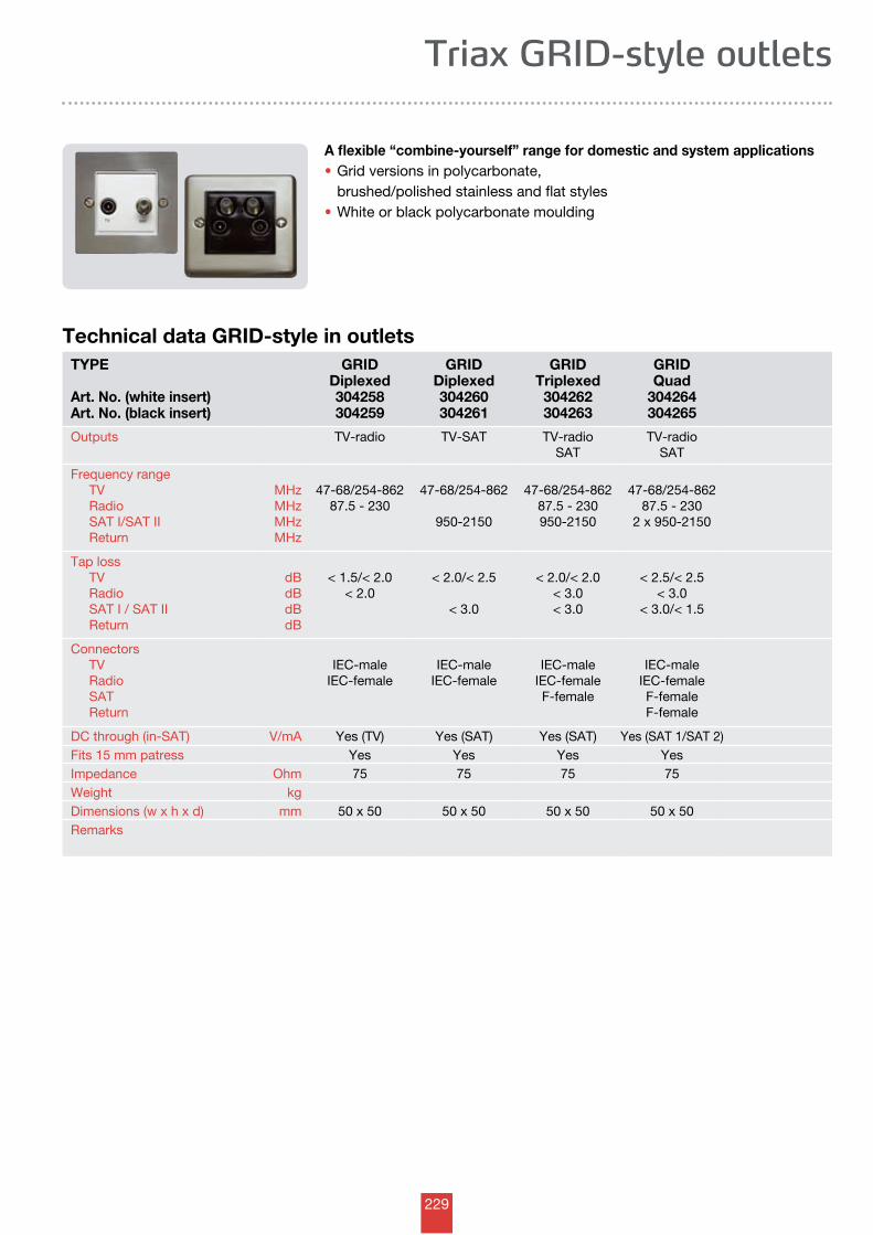
229
Technical data GRID-style in outletsTYPE
Art. No. (white insert)Art. No. (black insert)
GRIDDiplexed304258304259
GRIDDiplexed304260304261
GRID Triplexed304262304263
GRID Quad
304264304265
Outputs TV-radio TV-SAT TV-radioSAT
TV-radioSAT
Frequency range TV Radio SAT I/SAT II Return
MHzMHzMHzMHz
47-68/254-86287.5 - 230
47-68/254-862
950-2150
47-68/254-86287.5 - 230950-2150
47-68/254-86287.5 - 230
2 x 950-2150
Tap loss TV Radio SAT I / SAT II Return
dBdBdBdB
< 1.5/< 2.0< 2.0
< 2.0/< 2.5
< 3.0
< 2.0/< 2.0< 3.0< 3.0
< 2.5/< 2.5< 3.0
< 3.0/< 1.5
Connectors TV Radio SAT Return
IEC-maleIEC-female
IEC-maleIEC-female
IEC-maleIEC-femaleF-female
IEC-maleIEC-femaleF-femaleF-female
DC through (in-SAT) V/mA Yes (TV) Yes (SAT) Yes (SAT) Yes (SAT 1/SAT 2)Fits 15 mm patress Yes Yes Yes YesImpedance Ohm 75 75 75 75Weight kgDimensions (w x h x d) mm 50 x 50 50 x 50 50 x 50 50 x 50Remarks
Triax GRID-style outlets
A flexible “combine-yourself” range for domestic and system applications • Grid versions in polycarbonate, brushed/polished stainless and flat styles• White or black polycarbonate moulding
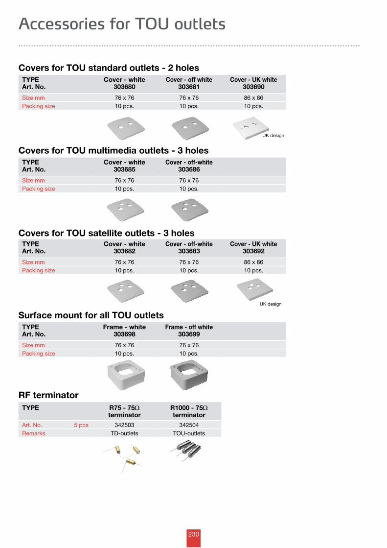
230
UK design
UK design
Accessories for TOU outlets
TYPEArt. No.
Cover - white303685
Cover - off-white303686
Size mm 76 x 76 76 x 76Packing size 10 pcs. 10 pcs.
RF terminatorTYPE R75 - 75W
terminatorR1000 - 75Wterminator
Art. No. 5 pcs 342503 342504Remarks TD-outlets TOU-outlets
TYPEArt. No.
Cover - white303680
Cover - off white303681
Cover - UK white303690
Size mm 76 x 76 76 x 76 86 x 86Packing size 10 pcs. 10 pcs. 10 pcs.
TYPEArt. No.
Frame - white303698
Frame - off white303699
Size mm 76 x 76 76 x 76Packing size 10 pcs. 10 pcs.
TYPEArt. No.
Cover - white303682
Cover - off-white303683
Cover - UK white303692
Size mm 76 x 76 76 x 76 86 x 86Packing size 10 pcs. 10 pcs. 10 pcs.
Covers for TOU standard outlets - 2 holes
Covers for TOU multimedia outlets - 3 holes
Covers for TOU satellite outlets - 3 holes
Surface mount for all TOU outlets
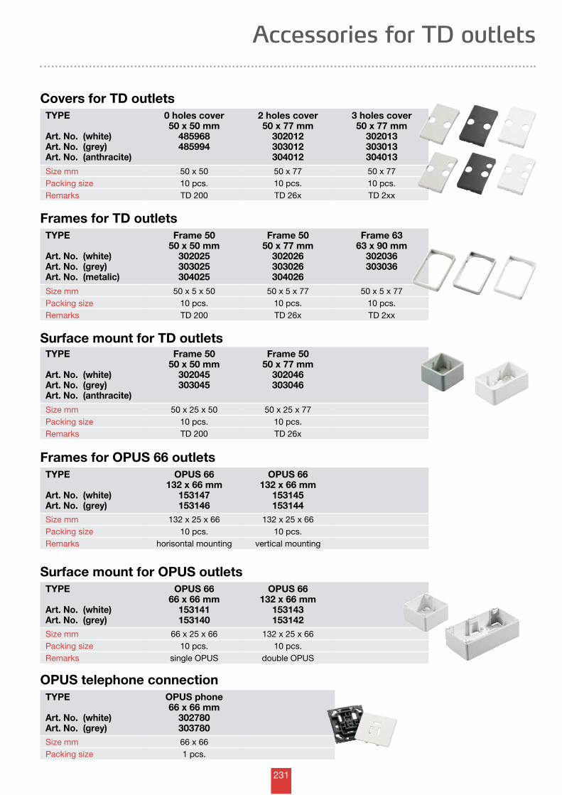
231
Accessories for TD outlets
TYPE
Art. No. (white)Art. No. (grey) Art. No. (anthracite)
0 holes cover50 x 50 mm
485968485994
2 holes cover50 x 77 mm
302012303012304012
3 holes cover50 x 77 mm
302013303013304013
Size mm 50 x 50 50 x 77 50 x 77Packing size 10 pcs. 10 pcs. 10 pcs.Remarks TD 200 TD 26x TD 2xx
Covers for TD outlets
TYPE
Art. No. (white)Art. No. (grey) Art. No. (metalic)
Frame 5050 x 50 mm
302025303025304025
Frame 5050 x 77 mm
302026303026304026
Frame 6363 x 90 mm
302036303036
Size mm 50 x 5 x 50 50 x 5 x 77 50 x 5 x 77Packing size 10 pcs. 10 pcs. 10 pcs.Remarks TD 200 TD 26x TD 2xx
Frames for TD outlets
TYPE
Art. No. (white)Art. No. (grey) Art. No. (anthracite)
Frame 5050 x 50 mm
302045303045
Frame 5050 x 77 mm
302046303046
Size mm 50 x 25 x 50 50 x 25 x 77Packing size 10 pcs. 10 pcs.Remarks TD 200 TD 26x
Surface mount for TD outlets
TYPE
Art. No. (white)Art. No. (grey)
OPUS 66132 x 66 mm
153147153146
OPUS 66132 x 66 mm
153145153144
Size mm 132 x 25 x 66 132 x 25 x 66Packing size 10 pcs. 10 pcs.Remarks horisontal mounting vertical mounting
Frames for OPUS 66 outlets
TYPE
Art. No. (white)Art. No. (grey)
OPUS 6666 x 66 mm
153141153140
OPUS 66132 x 66 mm
153143153142
Size mm 66 x 25 x 66 132 x 25 x 66Packing size 10 pcs. 10 pcs.Remarks single OPUS double OPUS
Surface mount for OPUS outlets
TYPE
Art. No. (white)Art. No. (grey)
OPUS phone66 x 66 mm
302780303780
Size mm 66 x 66Packing size 1 pcs.
OPUS telephone connection
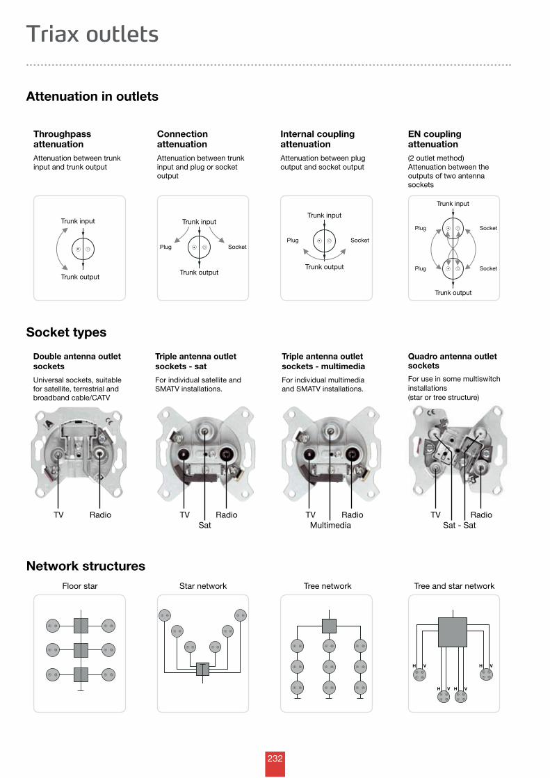
232
Trunk input
Trunk output
Trunk input
Trunk output
SocketPlugSocketPlug
Trunk input
Trunk output
Trunk input
Trunk output
SocketPlug
Plug Socket
H VH V
H V H V
Triax outlets
Throughpass attenuationAttenuation between trunk input and trunk output
Attenuation in outlets
Connection attenuationAttenuation between trunkinput and plug or socket output
Internal coupling attenuationAttenuation between plug output and socket output
EN coupling attenuation(2 outlet method)Attenuation between the out put s of two antenna sockets
Socket types
Triple antenna outlet sockets - sat
For individual satellite and SMATV installations.
Triple antenna outlet sockets - multimedia
For individual multimedia and SMATV installations.
Quadro antenna outlet sockets
For use in some multiswitch installations (star or tree structure)
TVSat
Radio TV RadioMultimedia
TV RadioSat - Sat
TV Radio
Network structuresFloor star Star network Tree network Tree and star network
Double antenna outlet sockets
Universal sockets, suitable for satellite, terrestrial and broadband cable/CATV
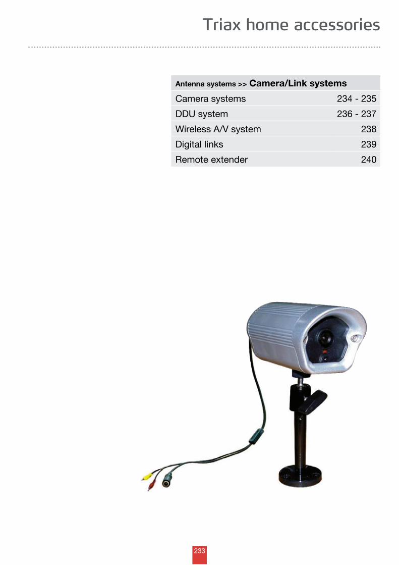
233
Triax home accessories
Antenna systems >> Camera/Link systems
Camera systems 234 - 235
DDU system 236 - 237
Wireless A/V system 238
Digital links 239
Remote extender 240
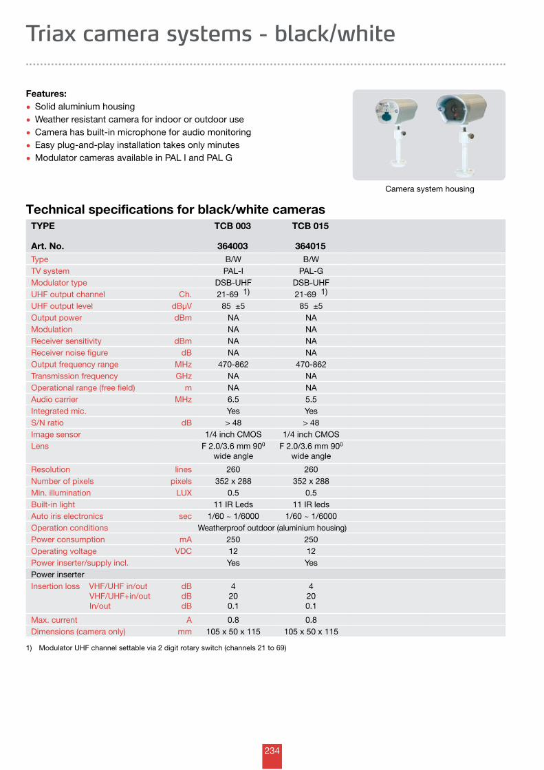
234
Triax camera systems - black/white
Technical specifications for black/white camerasTYPE
Art. No.
TCB 003
364003
TCB 015
364015Type B/W B/WTV system PAL-I PAL-GModulator type DSB-UHF DSB-UHFUHF output channel Ch. 21-69 1) 21-69 1)
UHF output level dBµV 85 ±5 85 ±5Output power dBm NA NAModulation NA NAReceiver sensitivity dBm NA NAReceiver noise figure dB NA NAOutput frequency range MHz 470-862 470-862Transmission frequency GHz NA NAOperational range (free field) m NA NAAudio carrier MHz 6.5 5.5Integrated mic. Yes YesS/N ratio dB > 48 > 48Image sensor 1/4 inch CMOS 1/4 inch CMOSLens F 2.0/3.6 mm 900
wide angleF 2.0/3.6 mm 900
wide angle
Resolution lines 260 260Number of pixels pixels 352 x 288 352 x 288Min. illumination LUX 0.5 0.5Built-in light 11 IR Leds 11 IR ledsAuto iris electronics sec 1/60 ~ 1/6000 1/60 ~ 1/6000Operation conditions Weatherproof outdoor (aluminium housing)Power consumption mA 250 250Operating voltage VDC 12 12Power inserter/supply incl. Yes YesPower inserterInsertion loss VHF/UHF in/out VHF/UHF+in/out In/out
dBdBdB
4200.1
4200.1
Max. current A 0.8 0.8Dimensions (camera only) mm 105 x 50 x 115 105 x 50 x 115
1) Modulator UHF channel settable via 2 digit rotary switch (channels 21 to 69)
Camera system housing
Features:
• Solid aluminium housing
• Weather resistant camera for indoor or outdoor use
• Camera has built-in microphone for audio monitoring
• Easy plug-and-play installation takes only minutes
• Modulator cameras available in PAL I and PAL G
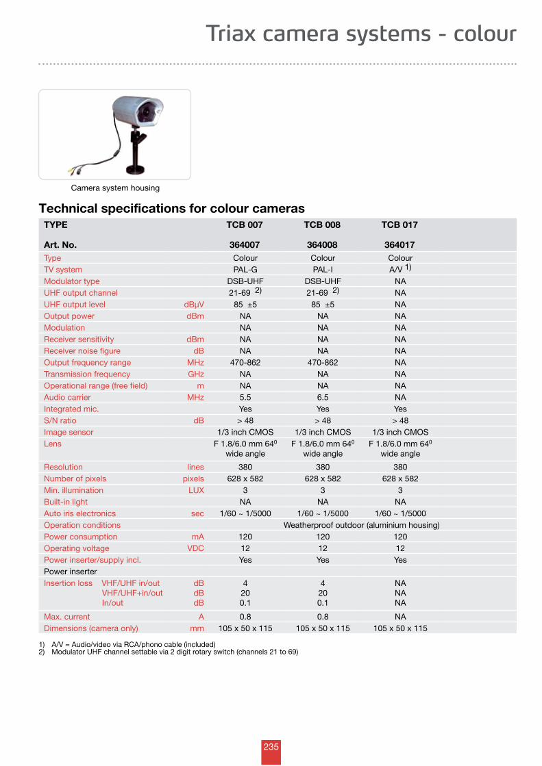
235
Triax camera systems - colour
Technical specifications for colour camerasTYPE
Art. No.
TCB 007
364007
TCB 008
364008
TCB 017
364017Type Colour Colour ColourTV system PAL-G PAL-I A/V 1)
Modulator type DSB-UHF DSB-UHF NAUHF output channel 21-69 2) 21-69 2) NAUHF output level dBµV 85 ±5 85 ±5 NAOutput power dBm NA NA NAModulation NA NA NAReceiver sensitivity dBm NA NA NAReceiver noise figure dB NA NA NAOutput frequency range MHz 470-862 470-862 NATransmission frequency GHz NA NA NAOperational range (free field) m NA NA NAAudio carrier MHz 5.5 6.5 NAIntegrated mic. Yes Yes YesS/N ratio dB > 48 > 48 > 48Image sensor 1/3 inch CMOS 1/3 inch CMOS 1/3 inch CMOSLens F 1.8/6.0 mm 640
wide angleF 1.8/6.0 mm 640
wide angleF 1.8/6.0 mm 640
wide angle
Resolution lines 380 380 380Number of pixels pixels 628 x 582 628 x 582 628 x 582Min. illumination LUX 3 3 3Built-in light NA NA NAAuto iris electronics sec 1/60 ~ 1/5000 1/60 ~ 1/5000 1/60 ~ 1/5000Operation conditions Weatherproof outdoor (aluminium housing)Power consumption mA 120 120 120Operating voltage VDC 12 12 12Power inserter/supply incl. Yes Yes YesPower inserterInsertion loss VHF/UHF in/out VHF/UHF+in/out In/out
dBdBdB
4200.1
4200.1
NANANA
Max. current A 0.8 0.8 NADimensions (camera only) mm 105 x 50 x 115 105 x 50 x 115 105 x 50 x 115
1) A/V = Audio/video via RCA/phono cable (included)2) Modulator UHF channel settable via 2 digit rotary switch (channels 21 to 69)
Camera system housing
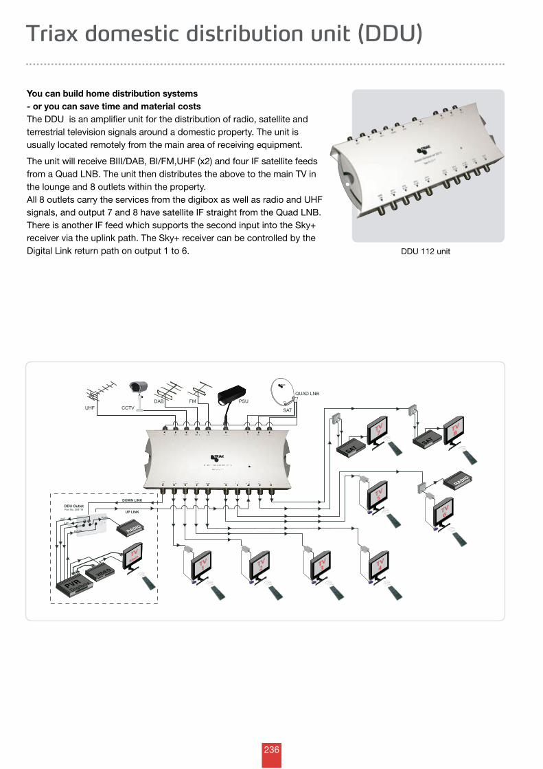
236
UHF CCTV DAB FM
TV
3 TV
3
SAT
TRIAX
TV
7 TV
7 TV
8 TV
8
SAT
RADIO
TV
5 TV
5
SAT
DOWN LINK
UP LINK
RADIO
PVR Digibox
TV
1 TV
1 TV
2 TV
2 TV
4 TV
4
QUAD LNB
SAT
TV
Radio
Return
TV
6 TV
6
DDU Outlet Part No. 304115
SAT
TV
Main TV
Main
VIDEO
PSU
Triax domestic distribution unit (DDU)
You can build home distribution systems - or you can save time and material costsThe DDU is an amplifier unit for the distribution of radio, satellite and terrestrial television signals around a domestic property. The unit is usually located remotely from the main area of receiving equipment.
The unit will receive BIII/DAB, BI/FM,UHF (x2) and four IF satellite feeds from a Quad LNB. The unit then distributes the above to the main TV in the lounge and 8 outlets within the property. All 8 outlets carry the services from the digibox as well as radio and UHF signals, and output 7 and 8 have satellite IF straight from the Quad LNB. There is another IF feed which supports the second input into the Sky+ receiver via the uplink path. The Sky+ receiver can be controlled by the Digital Link return path on output 1 to 6. DDU 112 unit
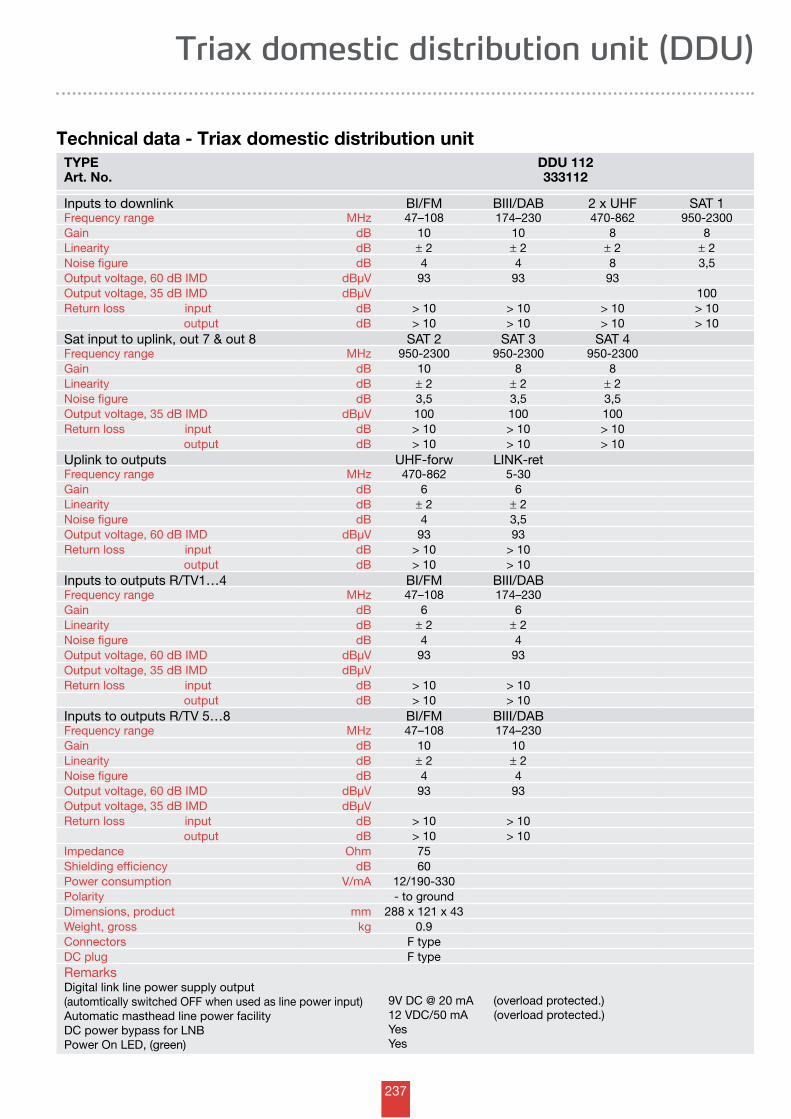
237
Triax domestic distribution unit (DDU)
Technical data - Triax domestic distribution unitTYPEArt. No.
DDU 112333112
Inputs to downlink BI/FM BIII/DAB 2 x UHF SAT 1Frequency range MHz 47–108 174–230 470-862 950-2300Gain dB 10 10 8 8Linearity dB ± 2 ± 2 ± 2 ± 2Noise figure dB 4 4 8 3,5Output voltage, 60 dB IMD dBµV 93 93 93Output voltage, 35 dB IMD dBµV 100Return loss input dB > 10 > 10 > 10 > 10 output dB > 10 > 10 > 10 > 10Sat input to uplink, out 7 & out 8 SAT 2 SAT 3 SAT 4Frequency range MHz 950-2300 950-2300 950-2300Gain dB 10 8 8Linearity dB ± 2 ± 2 ± 2Noise figure dB 3,5 3,5 3,5Output voltage, 35 dB IMD dBµV 100 100 100Return loss input dB > 10 > 10 > 10 output dB > 10 > 10 > 10Uplink to outputs UHF-forw LINK-retFrequency range MHz 470-862 5-30Gain dB 6 6Linearity dB ± 2 ± 2Noise figure dB 4 3,5Output voltage, 60 dB IMD dBµV 93 93Return loss input dB > 10 > 10 output dB > 10 > 10Inputs to outputs R/TV1…4 BI/FM BIII/DABFrequency range MHz 47–108 174–230Gain dB 6 6Linearity dB ± 2 ± 2Noise figure dB 4 4Output voltage, 60 dB IMD dBµV 93 93Output voltage, 35 dB IMD dBµVReturn loss input dB > 10 > 10 output dB > 10 > 10Inputs to outputs R/TV 5…8 BI/FM BIII/DABFrequency range MHz 47–108 174–230Gain dB 10 10Linearity dB ± 2 ± 2Noise figure dB 4 4Output voltage, 60 dB IMD dBµV 93 93Output voltage, 35 dB IMD dBµVReturn loss input dB > 10 > 10 output dB > 10 > 10Impedance Ohm 75Shielding efficiency dB 60Power consumption V/mA 12/190-330Polarity - to groundDimensions, product mm 288 x 121 x 43Weight, gross kg 0.9Connectors F typeDC plug F typeRemarksDigital link line power supply output(automtically switched OFF when used as line power input) Automatic masthead line power facilityDC power bypass for LNBPower On LED, (green)
9V DC @ 20 mA (overload protected.)12 VDC/50 mA (overload protected.)Yes Yes
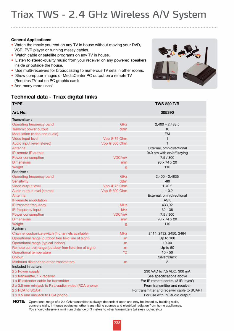
238
Triax TWS - 2.4 GHz Wireless A/V System
TYPE
Art. No.
TWS 220 T/R
305390
Transmitter :Operating frequency band GHz 2,400 – 2,483.5Transmit power output dBm 10Modulation (video and audio) FMVideo input level Vpp @ 75 Ohm 1Audio input level (stereo) Vpp @ 600 Ohm 1Antenna External, omnidirectionalIR-remote IR output 940 nm with on/off keyingPower consumption VDC/mA 7.5 / 300Dimensions mm 90 x 74 x 20Weight g 110Receiver :Operating frequency band GHz 2.400 - 2.4835Sensitivity dBm -80 Video output level Vpp @ 75 Ohm 1 ±0.2Audio output level (stereo) Vpp @ 600 Ohm 1 ± 0.2Antenna External, omnidirectionalIR-remote modulation ASKIR transmit frequency MHz 433,92IR frequency Input kHz 32 - 38Power consumption VDC/mA 7.5 / 300Dimensions mm 90 x 74 x 20Weight g 110System :Channel customize switch (4 channels available) MHz 2414, 2432, 2450, 2464Operational range (outdoor free field line of sight) m Up to 100 Operational range (typical indoor) m 10-30Remote control range (outdoor free field line of sight) m Up to 50Operational temperature ºC 10 - 50Colour Silver/BlackMinimum distance to other transmitters m 3Included in carton:2 x Power supply 230 VAC to 7.5 VDC, 300 mA1 x transmitter, 1 x receiver See specifications above1 x IR extender cable for transmitter For IR remote control (3 IR ‘eyes’)2 x 3.5 mm minijack to R+L-audio+video (RCA phono) From transmitter and receiver2 x RCA to SCART For transmitter and receiver cable to SCART1 x 3.5 mm minijack to RCA phono For use with PC audio output
NOTE: Operational range of a 2.4 GHz transmitter is always dependent upon and may be limited by building walls, concrete walls, in-house obstacles, other transmitting sources and electrical radiation from home appliances. You should observe a minimum distance of 3 meters to other transmitters (wireless router, etc.)
Technical data - Triax digital links
General Applications:• Watch the movie you rent on any TV in house without moving your DVD, VCR, PVR player or running messy cables.• Watch cable or satellite programs on any TV in house.• Listen to stereo-quality music from your receiver on any powered speakers inside or outside the house.• Use multi-receivers for broadcasting to numerous TV sets in other rooms.• Show computer images or MediaCenter PC output on a remote TV. (Requires TV-out on PC graphic card)• And many more uses!
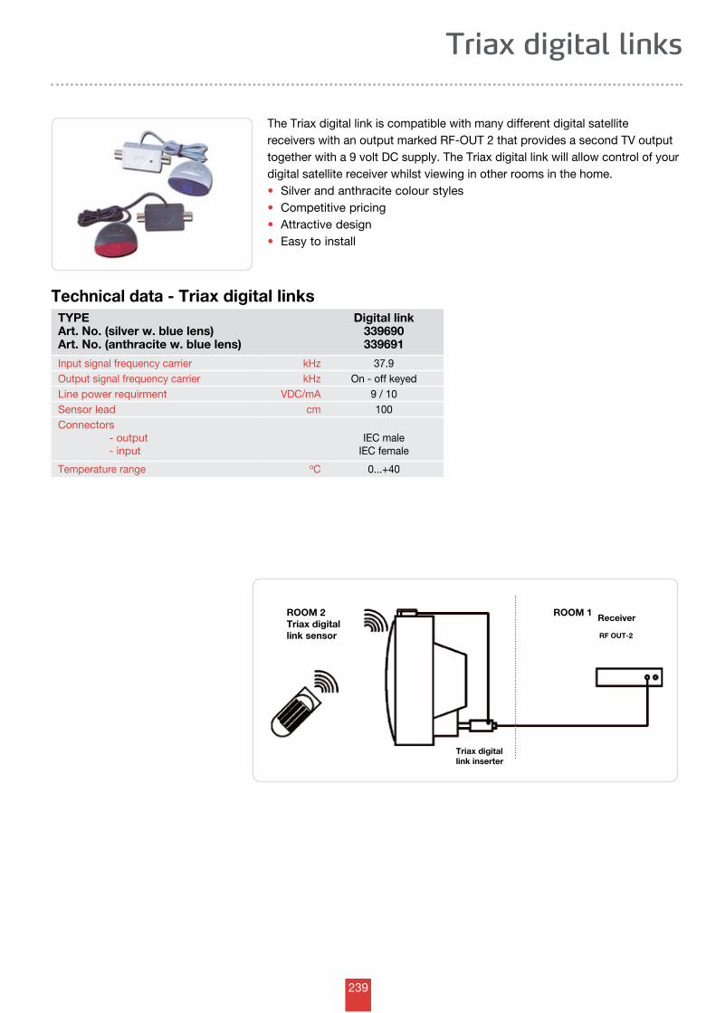
239
TYPEArt. No. (silver w. blue lens)Art. No. (anthracite w. blue lens)
Digital link339690339691
Input signal frequency carrier kHz 37.9Output signal frequency carrier kHz On - off keyedLine power requirment VDC/mA 9 / 10Sensor lead cm 100Connectors - output - input
IEC maleIEC female
Temperature range oC 0...+40
Triax digital links
Technical data - Triax digital links
The Triax digital link is compatible with many different digital satellite receivers with an output marked RF-OUT 2 that provides a second TV output together with a 9 volt DC supply. The Triax digital link will allow control of your digital satellite receiver whilst viewing in other rooms in the home.•Silver and anthracite colour styles•Competitive pricing•Attractive design •Easy to install
ROOM 2Triax digital link sensor
Triax digital link inserter
ReceiverROOM 1
RF OUT-2
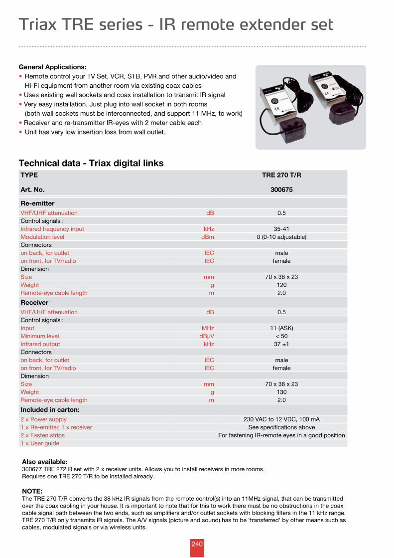
240
Triax TRE series - IR remote extender set
TYPE
Art. No.
TRE 270 T/R
300675
Re-emitterVHF/UHF attenuation dB 0.5Control signals :Infrared frequency input kHz 35-41Modulation level dBm 0 (0-10 adjustable)Connectorson back, for outlet IEC maleon front, for TV/radio IEC femaleDimensionSize mm 70 x 38 x 23Weight g 120Remote-eye cable length m 2.0
ReceiverVHF/UHF attenuation dB 0.5Control signals :Input MHz 11 (ASK)Minimum level dBµV < 50Infrared output kHz 37 ±1Connectorson back, for outlet IEC maleon front, for TV/radio IEC femaleDimensionSize mm 70 x 38 x 23Weight g 130Remote-eye cable length m 2.0
Included in carton:2 x Power supply 230 VAC to 12 VDC, 100 mA1 x Re-emitter, 1 x receiver See specifications above2 x Fasten strips For fastening IR-remote eyes in a good position1 x User guide
Also available:300677 TRE 272 R set with 2 x receiver units. Allows you to install receivers in more rooms. Requires one TRE 270 T/R to be installed already.
NOTE: The TRE 270 T/R converts the 38 kHz IR signals from the remote control(s) into an 11MHz signal, that can be transmitted over the coax cabling in your house. It is important to note that for this to work there must be no obstructions in the coax cable signal path between the two ends, such as amplifiers and/or outlet sockets with blocking filters in the 11 kHz range.TRE 270 T/R only transmits IR signals. The A/V signals (picture and sound) has to be ‘transferred’ by other means such as cables, modulated signals or via wireless units.
Technical data - Triax digital links
General Applications:• Remote control your TV Set, VCR, STB, PVR and other audio/video and Hi-Fi equipment from another room via existing coax cables•Uses existing wall sockets and coax installation to transmit IR signal•Very easy installation. Just plug into wall socket in both rooms (both wall sockets must be interconnected, and support 11 MHz, to work)•Receiver and re-transmitter IR-eyes with 2 meter cable each• Unit has very low insertion loss from wall outlet.
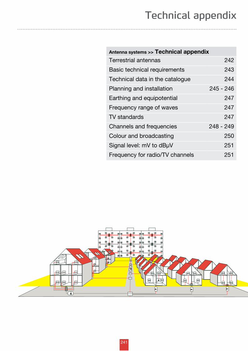
241
Technical appendix
Antenna systems >> Technical appendixTerrestrial antennas 242
Basic technical requirements 243
Technical data in the catalogue 244
Planning and installation 245 - 246
Earthing and equipotential 247
Frequency range of waves 247
TV standards 247
Channels and frequencies 248 - 249
Colour and broadcasting 250
Signal level: mV to dBµV 251
Frequency for radio/TV channels 251
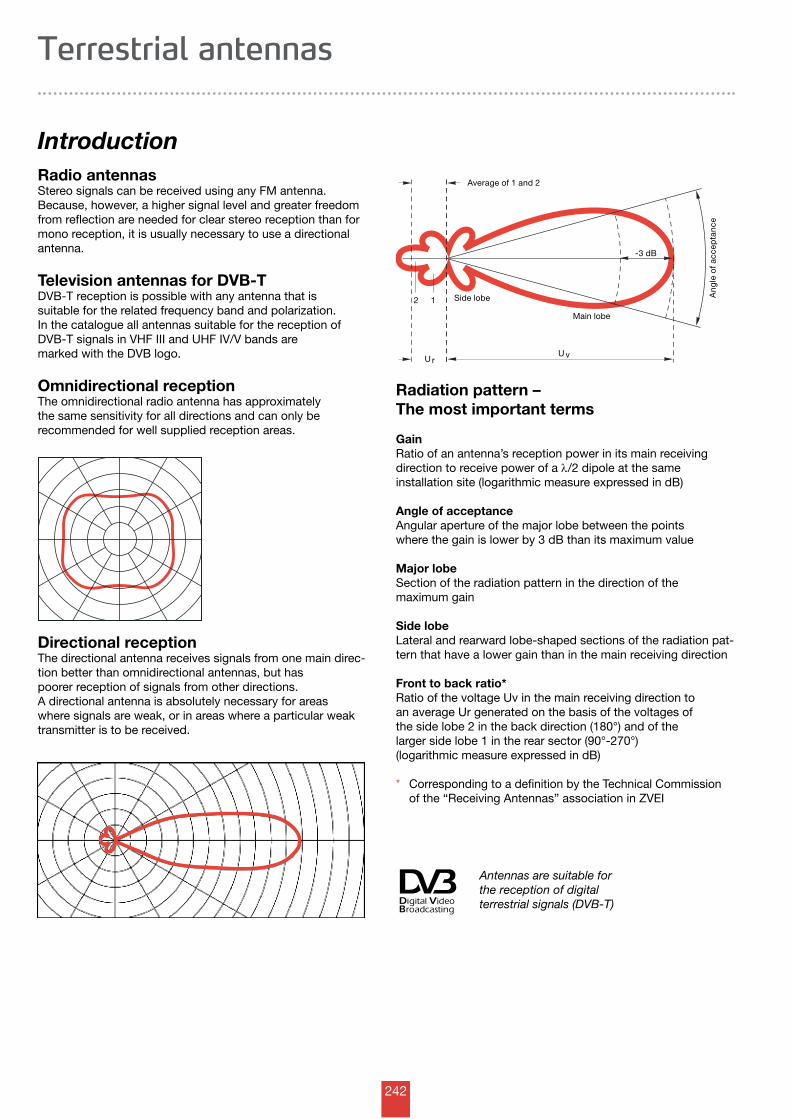
242
12 Side lobe
Main lobe
Ang
le o
f acc
epta
nce
-3 dB
rU
Average of 1 and 2
vU
Antennas are suitable for the reception of digital terrestrial signals (DVB-T)
IntroductionRadio antennasStereo signals can be received using any FM antenna. Because, however, a higher signal level and greater freedom from reflection are needed for clear stereo reception than for mono reception, it is usually necessary to use a directional antenna.
Television antennas for DVB-TDVB-T reception is possible with any antenna that is suitable for the related frequency band and polari zation. In the catalogue all antennas suitable for the reception of DVB-T signals in VHF III and UHF IV/V bands are marked with the DVB logo .
Omnidirectional receptionThe omnidirectional radio antenna has approximately the same sensitivity for all directions and can only be recommended for well supplied reception areas.
Directional receptionThe directional antenna receives signals from one main direc-tion better than omnidirectional antennas, but has poorer reception of signals from other directions. A directional antenna is absolutely necessary for areas where signals are weak, or in areas where a particular weak transmitter is to be received.
Radiation pattern – The most important terms
GainRatio of an antenna’s reception power in its main receiving direction to receive power of a l/2 dipole at the same installation site (logarithmic measure expressed in dB)
Angle of acceptanceAngular aperture of the major lobe between the points where the gain is lower by 3 dB than its maximum value
Major lobeSection of the radiation pattern in the direction of the maximum gain
Side lobeLateral and rearward lobe-shaped sections of the radiation pat-tern that have a lower gain than in the main receiving direction
Front to back ratio*Ratio of the voltage Uv in the main receiving direction to an average Ur generated on the basis of the voltages of the side lobe 2 in the back direction (180°) and of the larger side lobe 1 in the rear sector (90°-270°) (logarithmic measure expressed in dB)
* Corresponding to a definition by the Technical Commission of the “Receiving Antennas” association in ZVEI
Terrestrial antennas
243
All equipment and components in this catalogue meet, unless otherwise stated, the European standards for “Cable networks for television signals, sound signals and interactive services” from the standardization organization CENELEC, which have been adopted in national versions.
EN 50083-1 Safety requirementsEN 50083-1/A1EN 50083-1/A2EN 50083-2 Electromagnetic compatibility (EMC) of equipment
The equipment conforms to the uniform European “EMC directive” in accordance with legal requirements. For the ma-jority of the product groups in this catalogue, EN 50083-2 is relevant. In relation to the “Low voltage directive”, EN 60065 is the basis to which reference is made in EN 50083-1 “Safety requirements”. The CE marking for products in relation to EMC and the low voltage directive is based on these standards. In addition, CENELEC committee TC 209 has ratified European standards for equipment and system requirements for “Cable networks for television signals, sound signals and interactive services”.
EN 50083-3 Active broadband equipment for coaxial cable networksEN 50083-4 Passive broadband equipment for coaxial cable networksEN 50083-5 Headend equipmentEN 50083-6 Optical equipmentEN 50083-7 System requirementsEN 50083-8 Electromagnetic compatibility of cable networksEN 50083-9 Interfaces for CATV/SMATV headends and similar professional equipment for DVB/MPEG-2 transport streamsEN 50083-10 System performance for return paths
The system and equipment requirements are matched to each other in such a way that the minimum requirements for signal quality at the subscriber’s outlet can be met with a minimum of technical effort. In addition, requirements that result from use of both analogue and digital signal transmission have also been taken into account. The EN 50083 standards provide the network operator, planner and installer with concrete guidelines for network design and selection of appropriate network components. Hirschmann network components are developed to these standards and are marked in the catalogue by the relevant EN standard. The equipment standards (EN 50083 Parts 3...6) include fulfillment of the safety and EMC requirements (EN 50083 Parts 1 + 2). The legally required CE marking for antenna and telecommunication products refers to adherence to electromagnetic compatibility (EMC) limits and, from 1 Jan. 1997, to adherence to the low voltage directive.The CE marking does thus not imply fulfilment of the product and system requirements according to EN 50083- 3...-10. For this reason Triax indicates compliance with these basic
requirements on equipment (EN 50083-3...6) by explicitly noting the corresponding EN standard in the catalogue and in the operating instructions.
1.1 Marking of components for TV cable networks
With the CE marking Triax confirms the compliance of its products with the applicable EU directives (currently EMC and low voltage directives) as well as with the standards EN 50083-1, EN 50083-2 and EN 60065. For receivers the standards EN 55013, EN 55020 and EN 61000 are applied. The CE marking is placed on the product, on the packaging and/or included in the operating instructions. To prevent interference between TV cable networks and radio services, it is necessary to use components with sufficient shielding. Due to the varying conditions in the European countries, the shielding rate was defined in the European standard EN 50083-2 in two stages, the high quality class A and class B with reduced shielding rate values.
For example, the high radio density present in many parts of the world makes the usage of class A equipment necessary to prevent interactions, particularly with safety-relevant radio services such as air traffic control. As a differentiation in the appearance of the equipment for trade and installers is not possible, Triax and the other companies in the Fachverband Empfangsantennen- und Breitbandverteiltechnik im Zentral verband Elektrotechnik- und Elektroindustrie (ZVEI) e. V. mark the products with the protected trademark-symbol shown. In this way the higher quality of the equipment is made clear.
(See 3.3 Shielding rate) For compliance with the legal EMC requirements for TV cable networks, we expressly recommend the usage of class A components, including connecting cables so marked for terminal equipment.
Protection class 2 according to IEC 60417-5172 for components with power connection 230 V ~.
1. Basic technical requirements
Technical appendix
244
2. Technical data in the catalogue
Technical appendix
2.1. Characteristic impedanceUnless otherwise expressly mentioned, all technical data in the catalogue refer to a 75W impedance for the RF connections.
2.2. Operating temperatureAll passive units in the catalogue can be used within an operating temperature range of – 20 °C to + 60 °C. The mains-operated units meet the requirements of the EN 60065 standard within the temperature range from – 20 °C to + 50 °C. Operability of these units is nevertheless also maintained fully in the temperature range from –20 °C to + 60 °C. Individual units that deviate with regard to the above operating temperature range are specifically mentioned.
2.3. Mains voltageAll mains-operated units in the catalogue already meet the requirements of the IEC 60038 standard, with a rated voltage of 230 V~ +6% /–10%.
2.4. Wind loadFor antenna locations, safety regulations according to EN 50083-1 differentiate between two heights above ground (up to 20 m and above 20 m). They specify different dynamic pressure values for each height, q = 800 N/m2, and q = 1100 N/m2 respectively. The wind load values (horizontal and vertical) specified in this catalogue were determined using a dynamic pressure of q = 800 N/m2. If a value for q = 1100 N/m2 is needed, the value in the catalogue has to be multiplied by 1.37.
2.5. Permissible output level for active elec-tronic equipmentSpecification of the permissible output level is made according to EN 50083-3 “Active broadband equipment for coaxial cable networks” for a signal-to-noise ratio of:
• IMD = 60 dB for amplifiers for AM, QAM and FM signals (in SMATV/MATV, broadband cable, CATV installations)• IMD = 35 dB for amplifiers for FM signals only
(satellite IF transmission)
Now that this measurement method is standard throughout Europe, this important parameter has become transparent and comparable. With the aid of this information, the network planner and installer are able to determine the optimum amplifier gain (refer also to the planning instructions) to maintain the required minimum signal-to-noise ratios for a given number of channels. This procedure provides considerable advantages wherever new networks with a minimum number of amplifiers (cost ad-vantage) are planned or where over riding regulations apply for certain parts of the network. For example the permissible output level for a house connection amplifier to a house connection point is explicitly specified at CTB/CSO ≥ 66 dB. This means that the required signal quality (CTB/CSO ≥ 57 dBaccording to EN 50083-7) can be maintained up to the sub-scriber’s connection. Other permissible output levels are also given on the one hand for the CENELEC spacing (EN 50083-3) and on the other hand for full adjacent channel load of TV bands.
Maintaining the latter control limits allows for any channel load with analogue and digital TV signals (worst case: complete channel load with analogue and digital TV channels). Assigning only digital TV channels in the frequency range < 606 MHz makes it possible to raise the output level of the house connection amplifier by up to 2 dB.
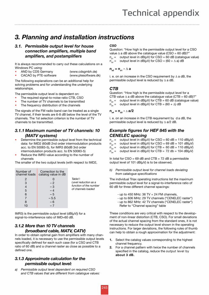
245
Number of Correction to the channel loads catalog value in dB
2 0 3 – 2 4 – 3 5 – 4 6 – 5 7 – 5.5 8 – 6 10 – 7
3. Planning and installation instructions
Technical appendix
3.1. Permissible output level for house connection amplifiers, multiple band amplifiers, and postamplifiers
It is always recommended to carry out these calculations on a Windows PC using: • AND by CDS Germany (www.cdsgmbh.de)• CACAO by PTE-software (www.ptesoftware.dk)
The following explanations can be an additional help for solving problems and for understanding the underlying relationships.
The permissible output level is dependent on:• The required signal-to-noise ratio CTB, CSO• The number of TV channels to be transmitted• The frequency distribution of the channels
The signals of the FM radio band can be treated as a single TV channel, if their levels are 6-8 dB below the level of the TV channels. The 1st selection criterion is the number of TV channels to be transmitted.
3.1.1 Maximum number of TV channels: 10 (MATV systems)• Determine the permissible output level from the technical data: for IMD2 (60dB 2nd order intermodulation products acc. to EN 50083-5), for IMR3 (60dB 3rd order intermodulation products acc. to EN 50083-5) • Reduce the IMR3 value according to the number of channels The smaller of the two output levels (with respect to IMD2,
Table1: Level reduction as a function of the number of channels loaded
IMR3) is the permissible output level (dB(µV)) for a signal-to-interference ratio of IMD=60 dB.
3.1.2 More than 10 TV channels (broadband cable, MATV, CATV)In order to obtain optimal gain from amplifiers with many chan-nels loaded, it is necessary to use the permissible output levels specifically defined for each such case (for a CSO and CTB ratio of 60 dB) and a channel raster as close as possible to a defined one.
3.1.3 Approximate calculation for the permissible output level:a) Permissible output level dependent on required CSO and CTB values that are different from catalogue values:
CSOQuestion: “How high is the permissible output level for a CSO value D a dB above the catalogue value (CSO = 60 dB)?”na1 = output level in dB(µV) for CSO = 60 dB (catalogue value)na2 = output level in dB(µV) for CSO = (60 + D a) dB
na2 = na1 - D a
i. e. on an increase in the CSO requirement by D a dB, the permissible output level is reduced by D a dB.
CTBQuestion: “How high is the permissible output level for a CTB value D a dB above the catalogue value (CTB = 60 dB)?”na3 = output level in dB(µV) for CTB = 60 dB (catalogue value)na4 = output level in dB(µV) for CTB = (60 + D) dB
na4 = na3 - D a/2
i. e. on an increase in the CTB requirement by d a dB, the permissible output level is reduced by D a/2 dB.
Example figures for HEF 845 with the CENELEC spacingna1 = output level in dB(µV) for CSO = 60 dB = 110 dB(µV)na2 = output level in dB(µV) for CSO = 69 dB = 101 dB(µV)na3 = output level in dB(µV) for CTB = 60 dB = 110 dB(µV)na4 = output level in dB(µV) for CTB = 72 db = 104 dB(µV)
In total for CSO = 69 dB and CTB = 72 dB a permissible output level of 101 dB(µV) is to be observed.
b) Permissible output level for channel loads deviating from catalogue specifications
The individual Triax operating instructions list the maximum permissible output level for a signal-to-interference ratio of 60 dB for three different channel spacings:
- up to 450 MHz: 36 TV + 24 FM channels, - up to 606 MHz: 29 TV channels (“CENELEC raster“) - up to 862 MHz: 42 TV channels (“CENELEC raster“) Refer to “Channel spacing” table
These conditions are very critical with respect to the develop-ment of non-linear distortion (CTB, CSO). For small deviations of the actual channel spacing from the standard ones, it is not necessary to reduce the output level shown in the operating instructions. For larger deviations, the following rules of thumb can help to obtain a rough approximation for the adjustment:
1. Select the catalog values corresponding to the highest channel frequency.2. For a channel pattern with twice the number of channels specified in the catalog, reduce the output level by about 3 dB.
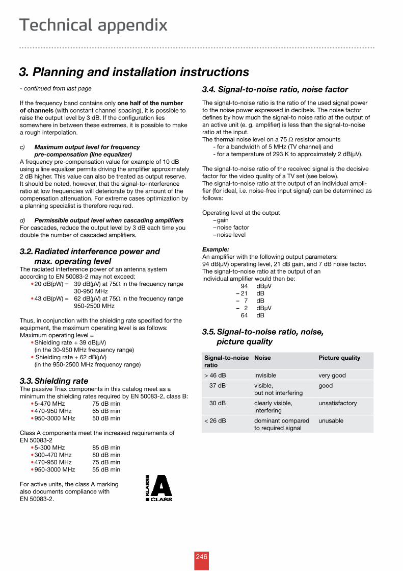
246
3. Planning and installation instructions
Technical appendix
- continued from last page
If the frequency band contains only one half of the number of channels (with constant channel spacing), it is possible to raise the output level by 3 dB. If the configuration lies somewhere in between these extremes, it is possible to make a rough interpolation.
c) Maximum output level for frequency pre-compensation (line equalizer)A frequency pre-compensation value for example of 10 dB using a line equalizer permits driving the amplifier approximately2 dB higher. This value can also be treated as output reserve. It should be noted, however, that the signal-to-interference ratio at low frequencies will deteriorate by the amount of the compensation attenu ation. For extreme cases optimization by a planning specialist is therefore required.
d) Permissible output level when cascading amplifiersFor cascades, reduce the output level by 3 dB each time you double the number of cascaded amplifiers.
3.2. Radiated interference power and max. operating levelThe radiated interference power of an antenna system according to EN 50083-2 may not exceed: • 20 dB(pW) = 39 dB(µV) at 75W in the frequency range 30-950 MHz • 43 dB(pW) = 62 dB(µV) at 75W in the frequency range 950-2500 MHz
Thus, in conjunction with the shielding rate specified for the equipment, the maximum operating level is as follows:Maximum operating level = • Shielding rate + 39 dB(µV) (in the 30-950 MHz frequency range) • Shielding rate + 62 dB(µV) (in the 950-2500 MHz frequency range)
3.3. Shielding rateThe passive Triax components in this catalog meet as a minimum the shielding rates required by EN 50083-2, class B: • 5-470 MHz 75 dB min • 470-950 MHz 65 dB min • 950-3000 MHz 50 dB min
Class A components meet the increased requirements of EN 50083-2 • 5-300 MHz 85 dB min • 300-470 MHz 80 dB min • 470-950 MHz 75 dB min • 950-3000 MHz 55 dB min
For active units, the class A markingalso documents compliance with EN 50083-2.
3.4. Signal-to-noise ratio, noise factor
The signal-to-noise ratio is the ratio of the used signal power to the noise power expressed in decibels. The noise factor defines by how much the signal-to noise ratio at the output of an active unit (e. g. amplifier) is less than the signal-to-noise ratio at the input.The thermal noise level on a 75 W resistor amounts - for a bandwidth of 5 MHz (TV channel) and - for a temperature of 293 K to approximately 2 dB(µV).
The signal-to-noise ratio of the received signal is the decisive factor for the video quality of a TV set (see below). The signal-to-noise ratio at the output of an individual ampli-fier (for ideal, i.e. noise-free input signal) can be determined as follows:
Operating level at the output – gain – noise factor – noise level
Example:An amplifier with the following output parameters: 94 dB(µV) operating level, 21 dB gain, and 7 dB noise factor.The signal-to-noise ratio at the output of an individual amplifier would then be: 94 dBµV – 21 dB – 7 dB – 2 dBµV 64 dB
3.5. Signal-to-noise ratio, noise, picture quality
Signal-to-noiseratio
Noise Picture quality
> 46 dB invisible very good
37 dB visible, but not interfering
good
30 dB clearly visible, interfering
unsatisfactory
< 26 dB dominant compared to required signal
unusable
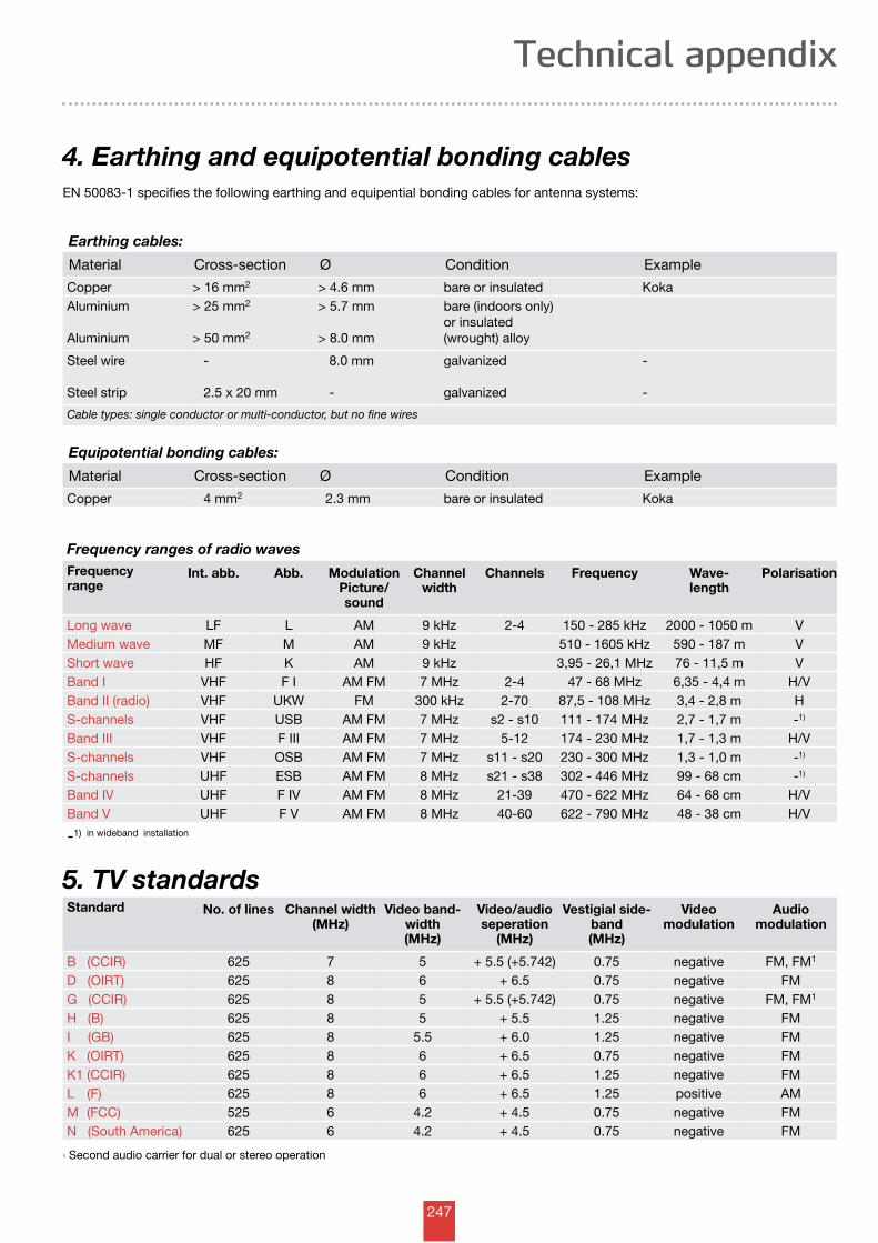
247
4. Earthing and equipotential bonding cables
Technical appendix
EN 50083-1 specifies the following earthing and equipential bonding cables for antenna systems:
Earthing cables:
Material Cross-section Ø Condition Example
Copper > 16 mm2 > 4.6 mm bare or insulated KokaAluminium
Aluminium
> 25 mm2
> 50 mm2
> 5.7 mm
> 8.0 mm
bare (indoors only) or insulated (wrought) alloy
Steel wire
Steel strip
- 2.5 x 20 mm
8.0 mm
-
galvanized
galvanized
-
-
Cable types: single conductor or multi-conductor, but no fine wires
Equipotential bonding cables:
Material Cross-section Ø Condition Example
Copper 4 mm2 2.3 mm bare or insulated Koka
Frequency ranges of radio wavesFrequencyrange
Int. abb. Abb. ModulationPicture/sound
Channelwidth
Channels Frequency Wave-length
Polarisation
Long wave LF L AM 9 kHz 2-4 150 - 285 kHz 2000 - 1050 m VMedium wave MF M AM 9 kHz 510 - 1605 kHz 590 - 187 m VShort wave HF K AM 9 kHz 3,95 - 26,1 MHz 76 - 11,5 m VBand I VHF F I AM FM 7 MHz 2-4 47 - 68 MHz 6,35 - 4,4 m H/VBand II (radio) VHF UKW FM 300 kHz 2-70 87,5 - 108 MHz 3,4 - 2,8 m HS-channels VHF USB AM FM 7 MHz s2 - s10 111 - 174 MHz 2,7 - 1,7 m -1)
Band III VHF F III AM FM 7 MHz 5-12 174 - 230 MHz 1,7 - 1,3 m H/VS-channels VHF OSB AM FM 7 MHz s11 - s20 230 - 300 MHz 1,3 - 1,0 m -1)
S-channels UHF ESB AM FM 8 MHz s21 - s38 302 - 446 MHz 99 - 68 cm -1)
Band IV UHF F IV AM FM 8 MHz 21-39 470 - 622 MHz 64 - 68 cm H/VBand V UHF F V AM FM 8 MHz 40-60 622 - 790 MHz 48 - 38 cm H/V
-1) in wideband installation
5. TV standards
1) Second audio carrier for dual or stereo operation
Standard No. of lines Channel width(MHz)
Video band-width(MHz)
Video/audio seperation
(MHz)
Vestigial side-band(MHz)
Videomodulation
Audio modulation
B (CCIR) 625 7 5 + 5.5 (+5.742) 0.75 negative FM, FM1
D (OIRT) 625 8 6 + 6.5 0.75 negative FMG (CCIR) 625 8 5 + 5.5 (+5.742) 0.75 negative FM, FM1
H (B) 625 8 5 + 5.5 1.25 negative FMI (GB) 625 8 5.5 + 6.0 1.25 negative FMK (OIRT) 625 8 6 + 6.5 0.75 negative FMK1 (CCIR) 625 8 6 + 6.5 1.25 negative FML (F) 625 8 6 + 6.5 1.25 positive AMM (FCC) 525 6 4.2 + 4.5 0.75 negative FMN (South America) 625 6 4.2 + 4.5 0.75 negative FM
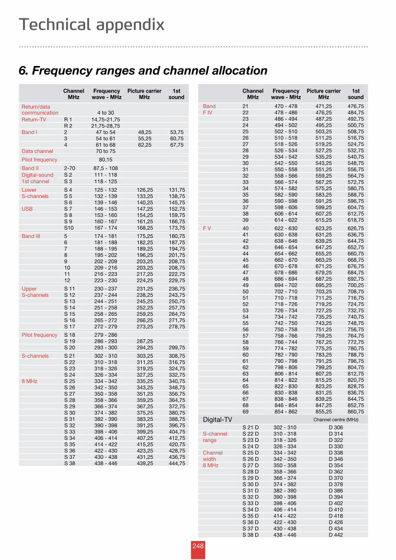
248
ChannelMHz
Frequencywave - MHz
Picture carrier MHz
1st sound
Return/data communication 4 to 30Return-TV R 1 14,75-21,75
R 2 21,75-28,75Band I 2 47 to 54 48,25 53,75
3 54 to 61 55,25 60,754 61 to 68 62,25 67,75
Data channel 70 to 75
Pilot frequency 80,15
Band II 2-70 87,5 - 108Digital-sound1st channel
S 2 111 - 118S 3 118 - 125
Lower S 4 125 - 132 126,25 131,75 S-channels S 5 132 - 139 133,25 138,75
S 6 139 - 146 140,25 145,75USB S 7 146 - 153 147,25 152,75
S 8 153 - 160 154,25 159,75S 9 160 - 167 161,25 166,75S10 167 - 174 168,25 173,75
Band III 5 174 - 181 175,25 180,756 181 - 188 182,25 187,757 188 - 195 189,25 194,758 195 - 202 196,25 201,759 202 - 209 203,25 208,7510 209 - 216 203,25 208,7511 216 - 223 217,25 222,7512 223 - 230 224,25 229,75
Upper S 11 230 - 237 231,25 236,75S-channels S 12 237 - 244 238,25 243,75
S 13 244 - 251 245,25 250,75S 14 251 - 258 252,25 257,75S 15 258 - 265 259,25 264,75S 16 265 - 272 266,25 271,75S 17 272 - 279 273,25 278,75
Pilot frequency S 18 279 - 286S 19 286 - 293 287,25S 20 293 - 300 294,25 299,75
S-channels S 21 302 - 310 303,25 308,75S 22 310 - 318 311,25 316,75S 23 318 - 326 319,25 324,75S 24 326 - 334 327,25 332,75
8 MHz S 25 334 - 342 335,25 340,75S 26 342 - 350 343,25 348,75S 27 350 - 358 351,25 356,75S 28 358 - 366 359,25 364,75S 29 366 - 374 367,25 372,75S 30 374 - 382 375,25 380,75S 31 382 - 390 383,25 388,75S 32 390 - 398 391,25 396,75S 33 398 - 406 399,25 404,75S 34 406 - 414 407,25 412,75S 35 414 - 422 415,25 420,75S 36 422 - 430 423,25 428,75S 37 430 - 438 431,25 436,75S 38 438 - 446 439,25 444,75
ChannelMHz
Frequencywave - MHz
Picture carrier MHz
1st sound
Band 21 470 - 478 471,25 476,75F IV 22 478 - 486 476,25 484,75
23 486 - 494 487,25 492,7524 494 - 502 495,25 500,7525 502 - 510 503,25 508,7526 510 - 518 511,25 516,7527 518 - 526 519,25 524,7528 526 - 534 527,25 532,7529 534 - 542 535,25 540,7530 542 - 550 543,25 548,7531 550 - 558 551,25 556,7532 558 - 566 559,25 564,7533 566 - 574 567,25 572,7534 574 - 582 575,25 580,7535 582 - 590 583,25 588,7536 590 - 598 591,25 596,7537 598 - 606 599,25 604,7538 606 - 614 607,25 612,7539 614 - 622 615,25 618,75
F V 40 622 - 630 623,25 626,7541 630 - 638 631,25 636,7542 638 - 646 639,25 644,7543 646 - 654 647,25 652,7544 654 - 662 655,25 660,7545 662 - 670 663,25 668,7546 670 - 678 671,25 676,7547 678 - 686 679,25 684,7548 686 - 694 687,25 692,7549 694 - 702 695,25 700,2550 702 - 710 703,25 708,7551 710 - 718 711,25 716,7552 718 - 726 719,25 724,7553 726 - 734 727,25 732,7554 734 - 742 735,25 740,7555 742 - 750 743,25 748,7556 750 - 758 751,25 756,7557 758 - 766 759,25 764,7558 766 - 744 767,25 772,7559 774 - 782 775,25 780,7560 782 - 790 783,25 788,7561 790 - 798 791,25 796,7562 798 - 806 799,25 804,7563 806 - 814 807,25 812,7564 814 - 822 815,25 820,7565 822 - 830 823,25 828,7566 830 - 838 831,25 836,7567 838 - 846 839,25 844,7568 846 - 854 847,25 852,7569 854 - 862 855,25 860,75
Digital-TV Channel centre (MHz)
S 21 D 302 - 310 D 306S-channel S 22 D 310 - 318 D 314range S 23 D 318 - 326 D 322
S 24 D 326 - 334 D 330Channel S 25 D 334 - 342 D 338width S 26 D 342 - 350 D 3468 MHz S 27 D 350 - 358 D 354
S 28 D 358 - 366 D 362S 29 D 366 - 374 D 370S 30 D 374 - 382 D 378S 31 D 382 - 390 D 386S 32 D 390 - 398 D 394S 33 D 398 - 406 D 402S 34 D 406 - 414 D 410S 35 D 414 - 422 D 418S 36 D 422 - 430 D 426S 37 D 430 - 438 D 434S 38 D 438 - 446 D 442
6. Frequency ranges and channel allocation
Technical appendix
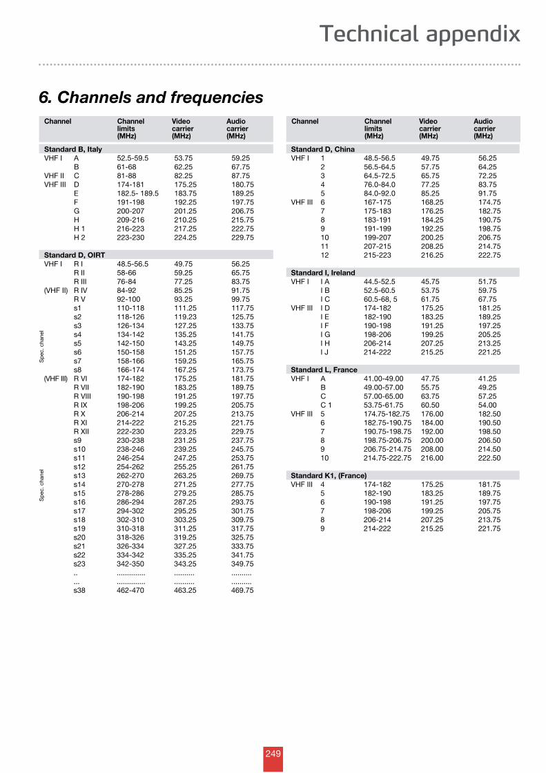
249
6. Channels and frequencies
Technical appendix
Standard B, ItalyVHF I A 52.5-59.5 53.75 59.25 B 61-68 62.25 67.75 VHF II C 81-88 82.25 87.75 VHF III D 174-181 175.25 180.75 E 182.5- 189.5 183.75 189.25 F 191-198 192.25 197.75 G 200-207 201.25 206.75 H 209-216 210.25 215.75 H 1 216-223 217.25 222.75 H 2 223-230 224.25 229.75 Standard D, OIRT VHF I R I 48.5-56.5 49.75 56.25 R II 58-66 59.25 65.75 R III 76-84 77.25 83.75(VHF II) R IV 84-92 85.25 91.75 R V 92-100 93.25 99.75 s1 110-118 111.25 117.75 s2 118-126 119.23 125.75 s3 126-134 127.25 133.75 s4 134-142 135.25 141.75 s5 142-150 143.25 149.75 s6 150-158 151.25 157.75 s7 158-166 159.25 165.75 s8 166-174 167.25 173.75 (VHF III) R VI 174-182 175.25 181.75 R VII 182-190 183.25 189.75 R VIII 190-198 191.25 197.75 R IX 198-206 199.25 205.75 R X 206-214 207.25 213.75 R XI 214-222 215.25 221.75 R XII 222-230 223.25 229.75 s9 230-238 231.25 237.75 s10 238-246 239.25 245.75 s11 246-254 247.25 253.75 s12 254-262 255.25 261.75 s13 262-270 263.25 269.75 s14 270-278 271.25 277.75 s15 278-286 279.25 285.75 s16 286-294 287.25 293.75 s17 294-302 295.25 301.75 s18 302-310 303.25 309.75 s19 310-318 311.25 317.75 s20 318-326 319.25 325.75 s21 326-334 327.25 333.75 s22 334-342 335.25 341.75 s23 342-350 343.25 349.75 .. .............. .......... .......... ... .............. .......... .......... s38 462-470 463.25 469.75
Standard D, ChinaVHF I 1 48.5-56.5 49.75 56.25 2 56.5-64.5 57.75 64.25 3 64.5-72.5 65.75 72.25 4 76.0-84.0 77.25 83.75 5 84.0-92.0 85.25 91.75VHF III 6 167-175 168.25 174.75 7 175-183 176.25 182.75 8 183-191 184.25 190.75 9 191-199 192.25 198.75 10 199-207 200.25 206.75 11 207-215 208.25 214.75 12 215-223 216.25 222.75 Standard I, Ireland VHF I I A 44.5-52.5 45.75 51.75 I B 52.5-60.5 53.75 59.75 I C 60.5-68, 5 61.75 67.75VHF III I D 174-182 175.25 181.25 I E 182-190 183.25 189.25 I F 190-198 191.25 197.25 I G 198-206 199.25 205.25 I H 206-214 207.25 213.25 I J 214-222 215.25 221.25 Standard L, France VHF I A 41.00-49.00 47.75 41.25 B 49.00-57.00 55.75 49.25 C 57.00-65.00 63.75 57.25 C 1 53.75-61.75 60.50 54.00 VHF III 5 174.75-182.75 176.00 182.50 6 182.75-190.75 184.00 190.50 7 190.75-198.75 192.00 198.50 8 198.75-206.75 200.00 206.50 9 206.75-214.75 208.00 214.50 10 214.75-222.75 216.00 222.50 Standard K1, (France)VHF III 4 174-182 175.25 181.75 5 182-190 183.25 189.75 6 190-198 191.25 197.75 7 198-206 199.25 205.75 8 206-214 207.25 213.75 9 214-222 215.25 221.75
Sp
ec. c
hane
l
Channel Channellimits(MHz)
Videocarrier(MHz)
Audiocarrier(MHz)
Sp
ec. c
hane
l
Channel Channellimits(MHz)
Videocarrier(MHz)
Audiocarrier(MHz)
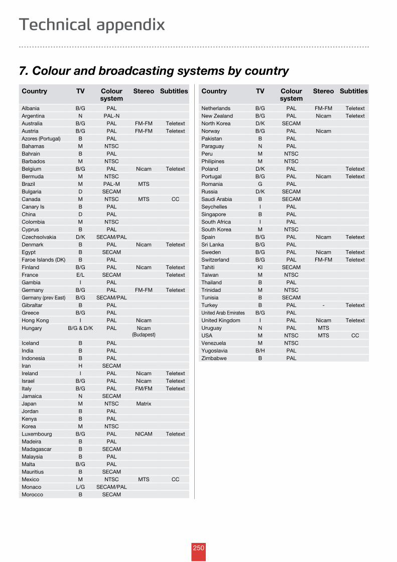
250
7. Colour and broadcasting systems by country
Technical appendix
Country TV Coloursystem
Stereo Subtitles
Albania B/G PAL Argentina N PAL-N Australia B/G PAL FM-FM Teletext Austria B/G PAL FM-FM Teletext Azores (Portugal) B PAL Bahamas M NTSC Bahrain B PAL Barbados M NTSC Belgium B/G PAL Nicam Teletext Bermuda M NTSC Brazil M PAL-M MTS Bulgaria D SECAM Canada M NTSC MTS CC Canary Is B PAL China D PAL Colombia M NTSC Cyprus B PAL Czechsolvakia D/K SECAM/PAL Denmark B PAL Nicam Teletext Egypt B SECAM Faroe Islands (DK) B PAL Finland B/G PAL Nicam Teletext France E/L SECAM Teletext Gambia I PAL Germany B/G PAL FM-FM Teletext Germany (prev East) B/G SECAM/PAL Gibraltar B PAL Greece B/G PAL Hong Kong I PAL Nicam Hungary B/G & D/K PAL Nicam
(Budapest)
Iceland B PAL India B PAL Indonesia B PAL Iran H SECAM Ireland I PAL Nicam Teletext Israel B/G PAL Nicam Teletext Italy B/G PAL FM/FM Teletext Jamaica N SECAM Japan M NTSC Matrix Jordan B PAL Kenya B PAL Korea M NTSC Luxembourg B/G PAL NICAM Teletext Madeira B PAL Madagascar B SECAM Malaysia B PAL Malta B/G PAL Mauritius B SECAM Mexico M NTSC MTS CC Monaco L/G SECAM/PAL Morocco B SECAM
Country TV Coloursystem
Stereo Subtitles
Netherlands B/G PAL FM-FM Teletext New Zealand B/G PAL Nicam Teletext North Korea D/K SECAM Norway B/G PAL Nicam Pakistan B PAL Paraguay N PAL Peru M NTSC Philipines M NTSC Poland D/K PAL Teletext Portugal B/G PAL Nicam Teletext Romania G PAL Russia D/K SECAM Saudi Arabia B SECAM Seychelles I PAL Singapore B PAL South Africa I PAL South Korea M NTSC Spain B/G PAL Nicam Teletext Sri Lanka B/G PAL Sweden B/G PAL Nicam Teletext Switzerland B/G PAL FM-FM Teletext Tahiti KI SECAM Taiwan M NTSC Thailand B PAL Trinidad M NTSC Tunisia B SECAM Turkey B PAL - Teletext United Arab Emirates B/G PAL United Kingdom I PAL Nicam Teletext Uruguay N PAL MTS USA M NTSC MTS CC Venezuela M NTSC Yugoslavia B/H PAL Zimbabwe B PAL
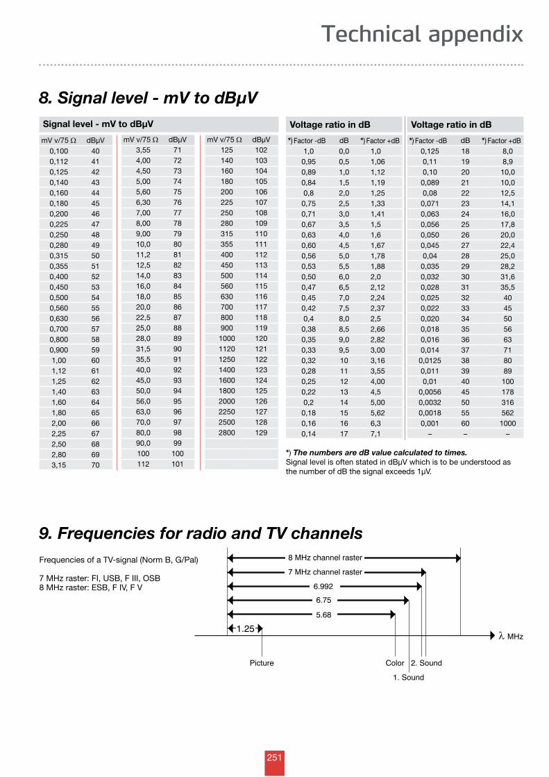
251
1.25
5.68
6.75
6.992
7 MHz channel raster
8 MHz channel raster
Picture Color 2. Sound
1. Sound
λ MHz
9. Frequencies for radio and TV channelsFrequencies of a TV-signal (Norm B, G/Pal)
7 MHz raster: FI, USB, F III, OSB8 MHz raster: ESB, F IV, F V
Signal level - mV to dBµV
mV v/75 W dBµV3,55 714,00 724,50 735,00 745,60 756,30 767,00 778,00 789,00 7910,0 8011,2 8112,5 8214,0 8316,0 8418,0 8520,0 8622,5 8725,0 8828,0 8931,5 9035,5 9140,0 9245,0 9350,0 9456,0 9563,0 9670,0 9780,0 9890,0 99100 100112 101
mV v/75 W dBµV0,100 400,112 410,125 420,140 430,160 440,180 450,200 460,225 470,250 480,280 490,315 500,355 510,400 520,450 530,500 540,560 550,630 560,700 570,800 580,900 591,00 601,12 611,25 621,40 631,60 641,80 652,00 662,25 672,50 682,80 693,15 70
mV v/75 W dBµV125 102140 103160 104180 105200 106225 107250 108280 109315 110355 111400 112450 113500 114560 115630 116700 117800 118900 119
1000 1201120 1211250 1221400 1231600 1241800 1252000 1262250 1272500 1282800 129
Voltage ratio in dB Voltage ratio in dB
*) Factor -dB dB *) Factor +dB *) Factor -dB dB *) Factor +dB1,0 0,0 1,0 0,125 18 8,00,95 0,5 1,06 0,11 19 8,90,89 1,0 1,12 0,10 20 10,00,84 1,5 1,19 0,089 21 10,00,8 2,0 1,25 0,08 22 12,50,75 2,5 1,33 0,071 23 14,10,71 3,0 1,41 0,063 24 16,00,67 3,5 1,5 0,056 25 17,80,63 4,0 1,6 0,050 26 20,00,60 4,5 1,67 0,045 27 22,40,56 5,0 1,78 0,04 28 25,00,53 5,5 1,88 0,035 29 28,20,50 6,0 2,0 0,032 30 31,60,47 6,5 2,12 0,028 31 35,50,45 7,0 2,24 0,025 32 400,42 7,5 2,37 0,022 33 450,4 8,0 2,5 0,020 34 500,38 8,5 2,66 0,018 35 560,35 9,0 2,82 0,016 36 630,33 9,5 3,00 0,014 37 710,32 10 3,16 0,0125 38 800,28 11 3,55 0,011 39 890,25 12 4,00 0,01 40 1000,22 13 4,5 0,0056 45 1780,2 14 5,00 0,0032 50 3160,18 15 5,62 0,0018 55 5620,16 16 6,3 0,001 60 10000,14 17 7,1 – – –
*) The numbers are dB value calculated to times.Signal level is often stated in dBµV which is to be understood as the number of dB the signal exceeds 1µV.
8. Signal level - mV to dBµV
Technical appendix

252
Contents from A to Z
00150030 1.1/7.3 Black Double shielded 100 m Plastic roll 203150031 1.1/7.3 Black Double shielded 500 m drum 203338365 102 FF/M 193338366 102 MM/F 193152015 2 x 0.5 power cable - grey 212152010 2 x 0.5 power cable - white 212152003 2 x 0.75 power cable - grey 212152004 2 x 0.75 power cable - white 212338106 203 B 2 Splitter 193345111 2TV Plus 164338125 309, 3 Splitter 193140030 38 mm x 1.5 m Mast 62140111 38 mm x 2 m Mast 62140031 38 mm x 3 m Mast 62140113 38 mm x 3 m Mast 62140112 38 mm x 4 m Mast 62140110 38 mm x 6 m Mast 62338130 407 4 Splitter 193338131 407 DC1, 4 splitter 193140025 42 mm x 2 m Mast for composition 62140115 42 mm x 3 m Mast 62140114 42 mm x 6 m Mast 62140028 50 mm x 2 m Mast for composition 62140029 50 mm x 3 m Mast for composition 62140126 50 mm x 3 m Mast 62140121 50 mm x 3 m Mast 63140008 50 mm x 4 m Mast 62140120 50 mm x 6 m Mast 62140122 50 mm x 6 m Mast 63342101 5020 attenuators 194336106 601/60 B power supply 197336121 602/60 B power supply 197336350 651/350 power supply 197312250 7000 FXX, 4 x UHF 52312264 70XX FYY, BIII/21-40 52312263 70XX FYY, BIII/41-60 52311122 71234 B Combiner 56311125 7132 G Combiner 56315103 720/ BIII 59315114 721/ UHF 59315115 741/ UHF 59312150 75 XY 52311304 7508 BIII, ch. 8 55311301 750X BI 55311303 750x BIII 55311140 75132 Combiner 56316110 753343 attenuators 194325830 8000/1 BI amp. 47325857 8000/1K BI channel 47325835 8000/2A BII 47325838 8000/3 BIII 47325856 8000/3K BIII channel 47325800 80065 UHF amp. 48325820 80065K amp. Ch. 21-46 48325821 80065K amp. Ch. 47-68 48325808 8100/3 BIII 47325804 81065 UHF amp. with limiter 48325824 81065K amp. Ch. 21-46 with limiter 48325825 81065K amp. Ch. 47-68 with limiter 48315122 821/ UHF 59315123 841/ UHF 59
A326850 A 334350/2360 A1 43326878 A 45/3153 43326880 A 45/XX 43326861 A 5053/7 A1 43326905 A XX A1, ch. 5-6, BIII 46326907 A XX A1, ch. 7-8 BIII 46326909 A XX A1, ch. 9-11, BIII 46326911 A XX A1, ch.12, BIII 46326980 A XXYY A2 multichannel 46326840 A XXYY/00 A1 43326859 A XXYY/Z A1 43326976 A88108 A1, FM 46322230 Accessory Box 153104579 Aerial 10el, ch. 5-12 12100582 Aerial 13el, ch. 5-11 12100022 Aerial 2el, ch. 2 foldable reflector 8100032 Aerial 2el,ch 3 foldable reflector 8100033 Aerial 3el,ch 3 foldable reflector 8104663 Aerial 4el, ch. 5-12 12103861 Aerial 4el, ch. 5-12 with F-connector 12106663 Aerial 4el, ch. 5-12,vertical 12100044 Aerial 4el,ch 4 9104665 Aerial 6el, ch. 5-12 12103862 Aerial 6el, ch. 5-12 with F-connector 12100279 Aerial, 10el, ch.6 14100329 Aerial, 10el, ch. 7 14100379 Aerial, 10el, ch. 8 15100429 Aerial, 10el, ch. 9 15100479 Aerial, 10el, ch.10 15100229 Aerial, 10el, ch.5 14100529 Aerial, 10el,ch. 11 15100282 Aerial, 13el, ch.6 14100482 Aerial, 13el, ch 10 15
100332 Aerial, 13el, ch. 7 14100382 Aerial, 13el, ch. 8 15100432 Aerial, 13el, ch. 9 15100532 Aerial, 13el, ch.11 15100232 Aerial, 13el, ch.5 14104602 Aerial, 3el, ch. 5-6 13104622 Aerial, 3el, ch. 7-8 13104603 Aerial, 4el, ch. 5-6 13104623 Aerial, 4el, ch. 7-8 13104643 Aerial, 4el, ch. 9-11 13100604 Aerial, 5el, ch. 5-6 13100624 Aerial, 5el, ch. 7-8 13100644 Aerial, 5el, ch. 9-11 13100305 Aerial, 6el, ch. 7 14100255 Aerial, 6el, ch.6 14100405 Aerial, 6el, ch. 9 15100355 Aerial, 6el, ch. 8 15100455 Aerial, 6el, ch. 10 15100205 Aerial, 6el, ch. 5 14100307 Aerial, 8el, ch. 7 14100257 Aerial, 8el, ch. 6 14100357 Aerial, 8el, ch. 8 15100407 Aerial, 8el, ch. 9 15100457 Aerial, 8el, ch. 10 15100207 Aerial, 8el, ch. 5 14100014 Aerial,2el, ch. 3 8100012 Aerial,3el, ch. 2-4 8100013 Aerial,3el, ch. 2-4, foldable reflektor 8300467 ALPS, Universal Quad LNB 92300468 ALPS, Universal Quattro LNB 92300464 ALPS, Universal Single LNB 92300462 ALPS, Universal Twin LNB 92346182 APS 007 power inserter 195324121 ARM 404 multiband-amp 4in1out 120324122 ARM 455 multiband-amp 5in1out 120324123 ARM 486 multiband-amp 6in1out 120153070 Arrow T25 Stitcher 74324596 ASA 02 PSU 230VAC, 15V/1,5ADC 119324587 ASC 011, Chassis for 10 modules 119324599 ASL 030,HF bridges 75 Ohm/IEC 119324598 ASR 075, 75 Ohm/IEC termination 119324593 ASU 040,ch21-69,att 0-18dB,40dB gain 119324594 ASU 050,ch21-69,att0-18dB,50dB gain 119324590 ASV 137,E2-E4,att.0-18dB,37dB gain 119324591 ASV 237,87,5-108 MHz,att 0-18dB,37dbgain 119324592 ASV 337,E5-E12,att0-18dB,37dB gain 119346413 ATM 4-12T 171346617 ATM 6-12T 171346812 ATM 8-12T 171346002 ATS 2 166346003 ATS 3 166346010 ATS 33 166346004 ATS 4 166346006 ATS 6 166346008 ATS 8 166346112 ATT 1-12 167346116 ATT 1-16 167346120 ATT 1-20 167346124 ATT 1-24 167346130 ATT 1-30 167346106 ATT 1-6 167346108 ATT 1-8 167346210 ATT 2-10 168346212 ATT 2-12 168346216 ATT 2-16 168346220 ATT 2-20 168346224 ATT 2-24 168346208 ATT 2-8 168346310 ATT 3-10 169346312 ATT 3-12 169346316 ATT 3-16 169346320 ATT 3-20 169346412 ATT 4-12 170346416 ATT 4-16 170346420 ATT 4-20 170346512 ATT 5-12 170346616 ATT 6-16 170
B300724 Basic - 3dg DuoBlock, Black 89300722 Basic - 6dg DuoBlock, Black 89300723 Basic - FlexiBlock, Black 89128601 Basic 60, Bulk, Ral 7035 84128602 Basic 60, Bulk, Ral 7035, (with south bracket) 84128701 Basic 75, Bulk, Ral 7035 84128801 Basic 85, Bulk, Ral 7035 84300729 Basic multiblock for 4xLNB excl. LNB & switch 89108011 BB grid ch. 21-69 23108013 BB grid ch. 21-69, 2 pcs. per pack 23108010 BB minigrid ch. 21-69, 4 pcs. per pack 23132015 Bottom clamp - 30-50 mm 69132018 Bottom clamp - 60 mm 69
C300738 Cable 1 m A/V Nicam for TDH 111300749 Cable 1,5 m A/V in-out for TDH 111300746 Cable 2,0m video/ monitor TDH 111153082 Cable clips, black, FC 11-13 (pack with 100 pcs) 73
153083 Cable clips, black, FC 13-15 (pack with 100 pcs) 73153084 Cable clips, black, FC 15-17 (pack with 100 pcs) 73153081 Cable clips, black, FC 9-11 (pack with 100 pcs) 73153004 Cable clips, Natural 6/25 (pack with 100 pcs) 73153008 Cable clips, Natural 7/25 (pack with 100 pcs) 73153010 Cable clips, Natural 7/35 (pack with 100 pcs) 73153013 Cable clips, Natural, 2x4mm (pack with 100 pcs) 73153001 Cable clips, Natural, 3x5mm (pack with 100 pcs) 73153003 Cable clips, Natural, 5/20 (pack with 100 pcs) 73153080 Cable clpis, black, FC 7-9 (pack with 100 pcs) 73153090 Cable duct - 16x16 white 72153092 Cable duct - 25x16 white 72153057 Cable grommet - black 74760056 Cable grommet - grey 74550000 Cable guards - 16 mm 72550001 Cable guards - 19 mm 72550002 Cable guards - 23 mm 72133053 Cable guards - Ø10-12 mm 72133054 Cable guards - Ø10-12 mm 72150110 Cable Stand 205153601 Cable stripper for RG 11 cable 210153602 Cable stripper for RG 6 cable 210153634 Cable support tool 210140135 Camping mast - indoor 63153540 CC-SP 01 cable assembly kit 211153542 CC-SP 02 cable assembly kit 211153544 CC-SP 04 cable assembly kit 211133225 Centre mount 27301379 Ch. 10 - 11 TDH Channel filter 110301380 Ch. 12 - S 11 TDH Channel filter 110301321 Ch. 21 - 22 TDH Channel filter 110301323 Ch. 23 - 24 TDH Channel filter 110301325 Ch. 25 - 26 TDH Channel filter 110301327 Ch. 27 - 28 TDH Channel filter 110301329 Ch. 29 - 30 TDH Channel filter 110301331 Ch. 31 - 32 TDH Channel filter 110301333 Ch. 33 - 34 TDH Channel filter 110301335 Ch. 35 - 36 TDH Channel filter 110301337 Ch. 37 - 38 TDH Channel filter 110301339 Ch. 39 - 40 TDH Channel filter 110301341 Ch. 41 - 42 TDH Channel filter 110301343 Ch. 43 - 44 TDH Channel filter 110301345 Ch. 45 - 46 TDH Channel filter 110301347 Ch. 47 - 48 TDH Channel filter 110301349 Ch. 49 - 50 TDH Channel filter 110301351 Ch. 51 - 52 TDH Channel filter 110301353 Ch. 53 - 54 TDH Channel filter 110301355 Ch. 55 - 56 TDH Channel filter 110301357 Ch. 57 - 58 TDH Channel filter 110301359 Ch. 59 - 60 TDH Channel filter 110301377 Ch. 6 - 7 TDH Channel filter 110301361 Ch. 61 - 62 TDH Channel filter 110301363 Ch. 63 - 64 TDH Channel filter 110301365 Ch. 65 - 66 TDH Channel filter 110301367 Ch. 67 - 68 TDH Channel filter 110301378 Ch. 8 - 9 TDH Channel filter 110130000 Chimney bracket set - 2-parts 70140032 Chimney bracket set - 38-50 mm 70130004 Chimney bracket set - double 70130002 Chimney bracket set - single 70130006 Chimney bracket set with 2 m mast 70130107 Clamp 68133100 Clamp woth bolts 68153071 Clips galv. (pack with 1000 pcs.) 74133011 Clips large 71153069 Clips White (pack with 1000 pcs.) 74300104 CM 01 Combi FM/UHF - PAL G 117300108 CM 01 Combi UHF - AU/NZ 117300107 CM 01 Combi VHF - AU/NZ 117300102 CM 01 Type UHF 117300116 CM 01 Type UHF + amplifier 117300101 CM 01 Type VHF 117490899 CM02U UHF Modulator 116490898 CM02V VHF Modulator 116153051 Coax coupling - grey 211153055 Coax coupling - white 211153043 Coax Female angle 209153022 Coax Female Angle - diecast housing 209153035 Coax Female angle Grey 209150180 Coax KOKA 100 198150181 Coax KOKA 100 198150182 Coax KOKA 100 198150193 Coax KOKA 100 198150186 Coax KOKA 100 black 202150187 Coax KOKA 100 black 202150120 Coax KOKA 6 199150121 Coax KOKA 6 199150122 Coax KOKA 6 199150131 Coax KOKA 6 199150144 Coax KOKA 6 CCS 199150149 Coax KOKA 6 CCS black 202150160 Coax KOKA 80 198150161 Coax KOKA 80 198150162 Coax KOKA 80 198150173 Coax KOKA 80 198150166 Coax KOKA 80 black 202150167 Coax KOKA 80 black 202
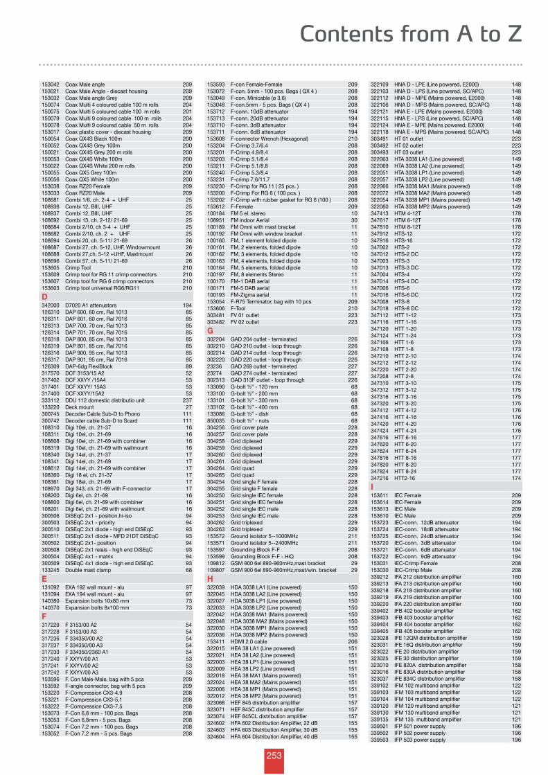
253
Contents from A to Z
153042 Coax Male angle 209153021 Coax Male Angle - diecast housing 209153032 Coax Male angle Grey 209150074 Coax Multi 4 coloured cable 100 m rolls 204150075 Coax Multi 5 coloured cable 100 m rolls 201150079 Coax Multi 9 coloured cable 100 m rolls 204150078 Coax Multi 9 coloured cable 50 m rolls 204153017 Coax plastic cover - diecast housing 209150054 Coax QX4S Black 100m 200150052 Coax QX4S Grey 100m 200150021 Coax QX4S Grey 200 m rolls 200150053 Coax QX4S White 100m 200150022 Coax QX4S White 200 m rolls 200150055 Coax QX5 Grey 100m 200150056 Coax QX5 White 100m 200153038 Coax RZ20 Female 209153033 Coax RZ20 Male 209108681 Combi 1/6, ch. 2-4 + UHF 25108936 Combi 12, BIII, UHF 25108937 Combi 12, BIII, UHF 25108692 Combi 13, ch. 2-12/ 21-69 25108684 Combi 2/10, ch 3-4 + UHF 25108682 Combi 2/10, ch. 2 + UHF 25108694 Combi 20, ch. 5-11/ 21-69 26108687 Combi 27, ch. 5-12, UHF, Windowmount 26108688 Combi 27,ch. 5-12 +UHF, Mastmount 26108696 Combi 57, ch. 5-11/ 21-69 26153605 Crimp Tool 210153609 Crimp tool for RG 11 crimp connectors 210153607 Crimp tool for RG 6 crimp connectors 210153603 Crimp tool universal RG6/RG11 210
D342000 D7020 A1 attenuators 194126310 DAP 600, 60 cm, Ral 1013 85126311 DAP 601, 60 cm, Ral 7016 85126313 DAP 700, 70 cm, Ral 1013 85126314 DAP 701, 70 cm, Ral 7016 85126318 DAP 800, 85 cm, Ral 1013 85126319 DAP 801, 85 cm, Ral 7016 85126316 DAP 900, 95 cm, Ral 1013 85126317 DAP 901, 95 cm, Ral 7016 85126309 DAP-6dg FlexiBlock 89317570 DCF 3153/15 A2 52317402 DCF XXYY /15A4 53317401 DCF XXYY/ 15A3 53317400 DCF XXYY/15A2 53333112 DDU 112 domestic distributio unit 237133220 Deck mount 27300745 Decoder Cable Sub-D to Phono 111300742 Decoder cable Sub-D to Scard 111108310 Digi 10el, ch. 21-37 16108311 Digi 10el, ch. 21-69 16108808 Digi 10el, ch. 21-69 with combiner 16108319 Digi 10el, ch. 21-69 with wallmount 16108340 Digi 14el, ch. 21-37 17108341 Digi 14el, ch. 21-69 17108612 Digi 14el, ch. 21-69 with combiner 17108360 Digi 18 el, ch. 21-37 17108361 Digi 18el, ch. 21-69 17108970 Digi 343, ch. 21-69 with F-connector 17108200 Digi 6el, ch. 21-69 16108800 Digi 6el, ch. 21-69 with combiner 16108201 Digi 6el, ch. 21-69 with wallmount 16300506 DiSEqC 2x1 - position,hi-iso 94300503 DiSEqC 2x1 - priority 94300510 DiSEqC 2x1 diode - high end DiSEqC 93300511 DiSEqC 2x1 diode - MFD 21DT DiSEqC 93300502 DiSEqC 2x1- position 94300508 DiSEqC 2x1 relais - high end DiSEqC 93300504 DiSEqC 4x1 - matrix 94300509 DiSEqC 4x1 diode - high end DiSEqC 93133245 Double mast clamp 68
E131092 EXA 192 wall mount - alu 97131094 EXA 194 wall mount - alu 97140380 Expansion bolts 10x80 mm 73140370 Expansion bolts 8x100 mm 73
F317229 F 3153/00 A2 54317228 F 3153/00 A3 54317236 F 334350/00 A2 54317237 F 334350/00 A3 54317233 F 334350/2360 A1 54317240 F XXYY/00 A1 53317241 F XXYY/00 A2 53317242 F XXYY/00 A3 53153596 F. Con Male-Male, bag with 5 pcs 209153592 F-angle connector, bag with 5 pcs 209153220 F-Compression CX3-4.9 208153221 F-Compression CX3-5,1 208153222 F-Compression CX3-7,5 208153073 F-Con 6,8 mm - 100 pcs. Bags 208153053 F-Con 6,8mm - 5 pcs. Bags 208153074 F-Con 7,2 mm - 100 pcs. Bags 208153052 F-Con 7,2 mm - 5 pcs. Bags 208
153593 F-con Female-Female 209153072 F-con. 5mm - 100 pcs. Bags ( QX 4 ) 208153049 F-con. Minicable (ø 3,6) 208153048 F-con.5mm - 5 pcs. Bags ( QX 4 ) 208153712 F-conn. 10dB attenuator 194153713 F-conn. 20dB attenuator 194153710 F-conn. 3dB attenuator 194153711 F-conn. 6dB attenuator 194153608 F-connector Wrench (Hexagonal) 210153204 F-Crimp 3.7/6.4 208153201 F-Crimp 4.9/8.4 208153203 F-Crimp 5.1/8.4 208153211 F-Crimp 5.1/8.8 208153240 F-Crimp 5.3/8.4 208153231 F-crimp 7.6/11.7 208153230 F-Crimp for RG 11 ( 25 pcs. ) 208153200 F-Crimp For RG 6 ( 100 pcs. ) 208153202 F-Crimp with rubber gasket for RG 6 (100 ) 208153612 F-Female 209100184 FM 5 el. stereo 10108951 FM indoor Aerial 30100189 FM Omni with mast bracket 11100192 FM Omni with window bracket 11100160 FM, 1 element folded dipole 10100161 FM, 2 elements, folded dipole 10100162 FM, 3 elements, folded dipole 10100163 FM, 4 elements, folded dipole 10100164 FM, 5 elements, folded dipole 10100197 FM, 8 elements Stereo 11100170 FM-1 DAB aerial 11100171 FM-5 DAB aerial 11100193 FM-Zigma aerial 11153054 F-R75 Terminator, bag with 10 pcs 209153606 F-Tool 210303481 FV 01 outlet 223303482 FV 02 outlet 223
G302204 GAD 204 outlet - terminated 226302210 GAD 210 outlet - loop through 226302214 GAD 214 outlet - loop through 226302220 GAD 220 outlet - loop through 22623236 GAD 269 outlet - termineted 22723274 GAD 274 outlet - terminated 227302313 GAD 313F outlet - loop through 226133090 G-bolt ½” - 120 mm 68133100 G-bolt ½” - 200 mm 68133101 G-bolt ½” - 300 mm 68133102 G-bolt ½” - 400 mm 68133086 G-bolt ½” - dish 68850035 G-bolt ½” - nuts 68304256 Grid cover plate 228304257 Grid cover plate 228304258 Grid diplexed 229304259 Grid diplexed 229304260 Grid diplexed 229304261 Grid diplexed 229304264 Grid quad 229304265 Grid quad 229304254 Grid single F female 228304255 Grid single F female 228304250 Grid single IEC female 228304251 Grid single IEC female 228304252 Grid single IEC male 228304253 Grid single IEC male 228304262 Grid triplexed 229304263 Grid triplexed 229153572 Ground isolator 5--1000MHz 211153571 Ground isolator 5--2400MHz 211153597 Grounding Block F-F 208153599 Grounding Block F-F - HiQ 208109812 GSM 900 6el 890-960mHz,mast bracket 29109807 GSM 900 6el 890-960mHz,mast/win. bracket 29
H322039 HDA 3038 LA1 (Line powered) 150322045 HDA 3038 LA2 (Line powered) 150322027 HDA 3038 LP1 (Line powered) 150322033 HDA 3038 LP2 (Line powered) 150322042 HDA 3038 MA1 (Mains powered) 150322048 HDA 3038 MA2 (Mains powered) 150322030 HDA 3038 MP1 (Mains powered) 150322036 HDA 3038 MP2 (Mains powered) 150153411 HDMI 2.0 cable 206322015 HEA 38 LA1 (Line powered) 151322021 HEA 38 LA2 (Line powered) 151322003 HEA 38 LP1 (Line powered) 151322009 HEA 38 LP2 (Line powered) 151322018 HEA 38 MA1 (Mains powered) 151322024 HEA 38 MA2 (Mains powered) 151322006 HEA 38 MP1 (Mains powered) 151322012 HEA 38 MP2 (Mains powered) 151323068 HEF 845 distribution amplifier 157323071 HEF 845C distribution amplifier 157323074 HEF 845CL distribution amplifier 157324602 HFA 602 Distribution Amplifier, 22 dB 155324603 HFA 603 Distribution Amplifier, 30 dB 155324604 HFA 604 Distribution Amplifier, 40 dB 155
322109 HNA D - LPE (Line powered, E2000) 148322103 HNA D - LPS (Line powered, SC/APC) 148322112 HNA D - MPE (Mains powered, E2000) 148322106 HNA D - MPS (Mains powered, SC/APC) 148322121 HNA E - LPE (Mains powered, E2000) 148322115 HNA E - LPS (Line powered, SC/APC) 148322124 HNA E - MPE (Mains powered, E2000) 148322118 HNA E - MPS (Mains powered, SC/APC) 148303491 HT 01 outlet 223303492 HT 02 outlet 223303493 HT 03 outlet 223322063 HTA 3038 LA1 (Line powered) 149322069 HTA 3038 LA2 (Line powered) 149322051 HTA 3038 LP1 (Line powered) 149322057 HTA 3038 LP2 (Line powered) 149322066 HTA 3038 MA1 (Mains powered) 149322072 HTA 3038 MA2 (Mains powered) 149322054 HTA 3038 MP1 (Mains powered) 149322060 HTA 3038 MP2 (Mains powered) 149347413 HTM 4-12T 178347617 HTM 6-12T 178347810 HTM 8-12T 178347912 HTS-12 172347916 HTS-16 172347002 HTS-2 172347012 HTS-2 DC 172347003 HTS-3 172347013 HTS-3 DC 172347004 HTS-4 172347014 HTS-4 DC 172347006 HTS-6 172347016 HTS-6 DC 172347008 HTS-8 172347018 HTS-8 DC 172347112 HTT 1-12 173347116 HTT 1-16 173347120 HTT 1-20 173347124 HTT 1-24 173347106 HTT 1-6 173347108 HTT 1-8 173347210 HTT 2-10 174347212 HTT 2-12 174347220 HTT 2-20 174347208 HTT 2-8 174347310 HTT 3-10 175347312 HTT 3-12 175347316 HTT 3-16 175347320 HTT 3-20 175347412 HTT 4-12 176347416 HTT 4-16 176347420 HTT 4-20 176347424 HTT 4-24 176347616 HTT 6-16 177347620 HTT 6-20 177347624 HTT 6-24 177347816 HTT 8-16 177347820 HTT 8-20 177347824 HTT 8-24 177347216 HTT2-16 174
I153611 IEC Female 209153614 IEC Female 209153613 IEC Male 209153610 IEC Male 209153723 IEC-conn. 12dB attenuator 194153724 IEC-conn. 18dB attenuator 194153725 IEC-conn. 24dB attenuator 194153720 IEC-conn. 3dB attenuator 194153721 IEC-conn. 6dB attenuator 194153722 IEC-conn. 9dB attenuator 194153031 IEC-Crimp Female 208153030 IEC-Crimp Male 208339212 IFA 212 distribution amplifier 160339213 IFA 213 distribution amplifier 160339218 IFA 218 distribution amplifier 160339219 IFA 219 distribution amplifier 160339220 IFA 220 distribution amplifier 160339402 IFB 402 booster amplifier 162339403 IFB 403 booster amplifier 162339404 IFB 404 booster amplifier 162339405 IFB 405 booster amplifier 162323028 IFE 12QM distribution amplifier 159323031 IFE 16Q distribution amplifier 159323022 IFE 20 distribution amplifier 159323025 IFE 30 distribution amplifier 159323010 IFE 820A distribution amplifier 158323016 IFE 830A distribution amplifier 158323037 IFE 834C distribution amplifier 158339102 IFM 102 multiband amplifier 122339103 IFM 103 multiband amplifier 122339104 IFM 104 multiband amplifier 122339120 IFM 120 multiband amplifier 121339130 IFM 130 multiband amplifier 121339135 IFM 135 multiband amplifier 121339501 IFP 501 power supply 196339502 IFP 502 power supply 196339503 IFP 503 power supply 196
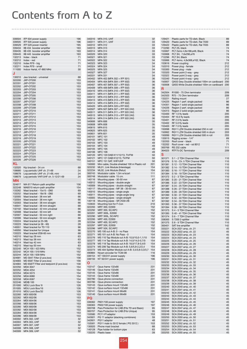
254
Contents from A to Z
339504 IFP 504 power supply 196339505 IFP 505 power supply 196339529 IFP 529 power inserter 195339434 IIB 434 booster amplifier 163339435 IIB 435 booster amplifier 163339445 IIB 445 booster amplifier 163132213 Index - black 71132212 Index - red 71132210 Index R79 - big 71132211 Index R79 - small 71111000 Indoor Aerial, 47-860 MHz 30
J130010 Jaw bracket - universal 68322200 JXP-OT200 153322201 JXP-OT201 153322202 JXP-OT202 153322203 JXP-OT203 153322204 JXP-OT204 153322205 JXP-OT205 153322206 JXP-OT206 153322207 JXP-OT207 153322208 JXP-OT208 153322209 JXP-OT209 153322210 JXP-OT210 153322211 JXP-OT211 153322212 JXP-OT212 153322213 JXP-OT213 153322214 JXP-OT214 153322215 JXP-OT215 153322216 JXP-OT216 153322217 JXP-OT217 153322218 JXP-OT218 153322219 JXP-OT219 153322220 JXP-OT220 153322221 JXP-OT221 153322222 JXP-OT222 153322223 JXP-OT223 153322224 JXP-OT224 153322225 JXP-OT225 153322226 JXP-OT226 153
KL132020 Kip bracket - 34 cm 68108680 Log-periodic UHF ch. 21-69 24108678 Log-periodic UHF ch. 21-69, mini 24108679 Log-periodic VHF/UHF ch. 5-12/21-69 24
MN324617 MA 617 Return-path amplifier 156322248 MA6510 return-path amplifier 154133262 Mast bracket - 15x15 - Ø60 69133252 Mast bracket - 18x18 - Ø60 69132005 Mast bracket - 38 mm left 66132004 Mast bracket - 38 mm right 66132003 Mast bracket - 38 mm straight 66140041 Mast bracket - 38 mm straight 68132102 Mast bracket - 42 mm universal 66132008 Mast bracket - 50 mm left 66132007 Mast bracket - 50 mm right 66132006 Mast bracket - 50 mm straight 66133224 Mast bracket (ø 25-38) 28133223 Mast bracket (ø 38 - 60) 28140051 Mast bracket for TD 110 96140050 Mast bracket for Unique 96133223 Mast bracket Ø38-60 mm 68140210 Mast top 28 mm 63140213 Mast top 38 mm 63140214 Mast top 42 mm 63140215 Mast top 50 mm 63322240 MCA 100 / 423 MHz 152322242 MCA 100 / 519 MHz 152322244 MCA 100 / 639 MHz 152324681 MD 3047 Filter (2 pcs.box) 156324683 MD 6587 Filter (2 pcs.box) 156324684 MD 6587T Filter and testpoint (2 pcs.box) 156322250 MDA 3047 154322252 MDA 4254 154322254 MDA 5573 154322256 MDA 6080 154322258 MDA 6587 154322246 MDIB 100 154251000 MDU Lock Box/ 8 126251005 MDU Lock Box/16 126251010 MDU Lock Box/32 126322260 MEX 600/06 153322262 MEX 602/06 153322264 MEX 604/06 153322266 MEX 606/06 153322280 MEX 800/08 153322282 MEX 802/08 153322284 MEX 804/08 153322286 MEX 806/08 153340302 MFA 302, UHF 32340304 MFA 304, UHF 32340307 MFA 307, UHF 32340308 MFA 308, UHF 32340309 MFA 309, UHF 32
340310 MFA 310, UHF 32340311 MFA 311, UHF 33340312 MFA 312 33340313 MFA 313 33340314 MFA 314 33340320 MFA 320 33340321 MFA 321 33340322 MFA 322 34340323 MFA 323 34340324 MFA 324 34340325 MFA 325 34340327 MFA 327 34340331 MFA 331 34340402 MFA 402 (MFA 302 + IFP 501) 36340404 MFA 404 (MFA 304 + IFP 502) 36340407 MFA 407 (MFA 307 + IFP 502) 36340409 MFA 409 (MFA 309 + IFP 502) 36340410 MFA 410 (MFA 310 + IFP 502) 36340411 MFA 411 (MFA 311 + IFP 502) 36340412 MFA 412 (MFA 312 + IFP 502) 36340413 MFA 413 (MFA 313 + IFP 502) 36340414 MFA 414 (MFA 314 + IFP 502) 36340420 MFA 420 (MFA 320 x IFP 502) 36340507 MFA 507 (MFA 307 + IFP 503 24V) 36340511 MFA 511 (MFA 311 + IFP 503 24V) 36340513 MFA 513 (MFA 313 + IFP 503 24V) 36340514 MFA 514 (MFA 314 + IFP 503 24V) 36340606 MFA 606 35340608 MFA 608 35340615 MFA 615 35340625 MFA 625 35340651 MFA 651 35340101 MFC 101 49340102 MFC 102 49340103 MFC 103 49340104 MFC 104 49340105 MFC 105 49340106 MFC 106 49340120 MFC 120 DAB K11/12/13, TV/FM 50340121 MFC 121 DAB K12/13, TV/FM 50340151 MFC 151 SAT, VHF/UHF 50150000 Mini cable, Double shielded 100 m Plastic roll 201322232 ML01, Link Module (Interstage) 154322234 ML02, Link Module (Retur) 154300743 Modulator cable 1,5m w/scart 111300748 Modulator cable 15 cm. 111140116 Mounting pipes - 30-50 mm 67140012 Mounting pipes - double angle 67140009 Mounting pipes - double straight 67140117 Mounting pipes - MF 38 - 30-50 mm 67140010 Mounting pipes - single angle 67140011 Mounting pipes - single angle long 67140005 Mounting pipes - single straight 67140118 Mounting pipes - SR 2530-2B 67153633 Mounting tool for F-Con 210322293 MRT 300, E2000 152322292 MRT 300, SC/APC 152322291 MRT 300L, E2000 152322290 MRT 300L, SC/APC 152322295 MRT 400, E2000 152322294 MRT 400, SC/APC 152322297 MRT 50X, E2000 152322296 MRT 50X, SC/APC 152322270 MS 100 out A-B: 0 - no Pass 154322271 MS 101 out A-B: No Pass - 0 154322276 MS 110 Tap Module out A-B: 10,0/10,0-1,1/10 154322277 MS 114 Tap Module out A-B: 14,0/14,0-0,7/0 154322278 MS 118 Tap Module out A-B: 18,0/17,8-0,4/0 154322274 MS 206 Tap Module out A-B: 5,6/5,8-2,2/2,4 154322273 MS 404 Splitter Module out A-B: 3,5/3,8-3,3/3,7 154490884 Nicam encoder for TCM-08 116336154 NT 130/241 power supply 196336150 NT 50/241 power supply 196
O153147 Opus frame 132x66 231153146 Opus frame 132x66 231153145 Opus frame 132x66 231153144 Opus frame 132x66 231302780 Opus phone connection 231303780 Opus phone connection 231153143 Opus surface mount 132x66 231153142 Opus surface mount 132x66 231153141 Opus surface mount 66x66 231153140 Opus surface mount 66x66 231
PQ336362 P601/100 power supply 197336363 P602/100 power supply 197300708 Para Protection for LNB (Fits TD and Basic) 95300707 Para Protection for LNB (Fits Unique) 95153580 PC11-Ff adaptor 153342601 PG 11 adaptor (stacking combiners) 59342601 PG11 adaptor 48153581 PG11 male to 3512 female ( PG 3512 ) 153130020 Phone mast bracket 68140128 Pipe holder for bottom pipe 63133220 Plastic base 28
129421 Plastic parts for TD-dish, Black 89129420 Plastic parts for TD-dish, Ral 7030 89129422 Plastic parts for TD-dish, Ral 7035 89712290 PLT 2S, black 74153067 PLT 2smo 4,8x188,ø48, Black 74153068 PLT 3H, 7,6x290,ø76 74712296 PLT 3H, Black 74153066 PLT 4smo, 4,8x368,ø102, Black 74153616 Power coupling 212153310 Power plug - female 212153300 Power plug - male 212153320 Power point 2-way - grey 212153322 Power point 3-way - grey 212153340 Power point 4-way - grey 212150007 QX5S Grey Double shielded 100m on cardboard 200150008 QX5S White Double shielded 100m on cardboard 200
R342504 R1000 - 75 Ohm terminator 209342503 R75 - 75 Ohm terminator 209133221 Railing mount 27124225 Region 1 perf. single packed 86124351 Region 1 solid single packed 86124226 Region 2 perf. single packed 86124313 Region 2 solid single packed 86153400 RF 1.5 fly leads 205153404 RF 10.0 fly leads 205153401 RF 2.5 fly leads 205153402 RF 5.0 fly leads 205153403 RF 7.5 fly leads 205150098 RG11 LZW Double shielded 250 m roll 203150062 RG11 LZW Double shielded 500 m drum 203150099 RG11 LZW Double shielded 500 m roll 203133015 Rigging screw - 1/4” 69132203 Roof cover - black 71132202 Roof cover - red - ral 8012 71300769 RS 232 cable 111364025 RTF75-DC Terminator 209
S301371 S 1 - 2 TDH Channel filter 110301376 S 10 - Ch. 5 TDH Channel filter 110301381 S 12 - 13 TDH Channel filter 110301382 S 14 - 15 TDH Channel filter 110301383 S 16 - 17 TDH Channel filter 110301384 S 18 - 19 TDH Channel filter 110301372 S 2 - 3 TDH Channel filter 110301385 S 20 - 21 TDH Channel filter 110301386 S 22 - 23 TDH Channel filter 110301387 S 24 - 25 TDH Channel filter 110301388 S 26 - 27 TDH Channel filter 110301389 S 28 - 29 TDH Channel filter 110301390 S 30 - 31 TDH Channel filter 110301391 S 32 - 33 TDH Channel filter 110301392 S 34 - 35 TDH Channel filter 110301393 S 36 - 37 TDH Channel filter 110301394 S 38 - 39 TDH Channel filter 110301373 S 4 - 5 TDH Channel filter 110301395 S 40 - 41 TDH Channel filter 110301374 S 6 - 7 TDH Channel filter 110338300 S 7200 2-splitter 193301375 S 8 - 9 TDH Channel filter 110300401 SAT line amplifier 142333221 SCA 2021 amp, ch. 21 45333222 SCA 2022 amp, ch. 22 45333223 SCA 2023 amp, ch. 23 45333224 SCA 2024 amp, ch. 24 45333225 SCA 2025 amp, ch. 25 45333226 SCA 2026 amp, ch. 26 45333227 SCA 2027 amp, ch. 27 45333228 SCA 2028 amp, ch. 28 45333229 SCA 2029 amp, ch. 29 45333230 SCA 2030 amp, ch. 30 45333231 SCA 2031 amp, ch. 31 45333232 SCA 2032 amp, ch. 32 45333233 SCA 2033 amp, ch. 33 45333234 SCA 2034 amp, ch. 34 45333235 SCA 2035 amp, ch. 35 45333236 SCA 2036 amp, ch. 36 45333237 SCA 2037 amp, ch. 37 45333238 SCA 2038 amp, ch. 38 45333239 SCA 2039 amp, ch. 39 45333240 SCA 2040 amp, ch. 40 45333241 SCA 2041 amp, ch. 41 45333242 SCA 2042 amp, ch. 42 45333243 SCA 2043 amp, ch. 43 45333244 SCA 2044 amp, ch. 44 45333245 SCA 2045 amp, ch. 45 45333246 SCA 2046 amp, ch. 46 45333247 SCA 2047 amp, ch. 47 45333248 SCA 2048 amp, ch. 48 45333249 SCA 2049 amp, ch. 49 45333250 SCA 2050 amp, ch. 50 45333251 SCA 2051 amp, ch. 51 45333252 SCA 2052 amp, ch. 52 45333253 SCA 2053 amp, ch. 53 45333254 SCA 2054 amp, ch. 54 45333255 SCA 2055 amp, ch. 55 45
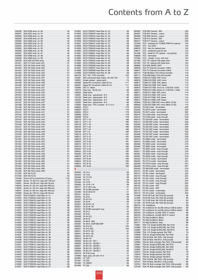
255
Contents from A to Z
333256 SCA 2056 amp, ch. 56 45333257 SCA 2057 amp, ch. 57 45333258 SCA 2058 amp, ch. 58 45333259 SCA 2059 amp, ch. 59 45333260 SCA 2060 amp, ch. 60 45333263 SCA 2063 amp, ch. 63 45333264 SCA 2064 amp, ch. 64 45333265 SCA 2065 amp, ch. 65 45333266 SCA 2066 amp, ch. 66 45333267 SCA 2067 amp, ch. 67 45333268 SCA 2068 amp, ch. 68 45333269 SCA 2069 amp, ch. 69 45333220 SCA 439-443 MHz amp 45331421 SCF 21/15A3 comb, K21 57331422 SCF 22/15A3 comb, K22 57331423 SCF 23/15A3 comb, K23 57331424 SCF 24/15A3 comb, K24 57331425 SCF 25/15A3 comb, K25 57331426 SCF 26/15A3 comb, K26 57331427 SCF 27/15A3 comb, K27 57331428 SCF 28/15A3 comb, K28 57331429 SCF 29/15A3 comb, K29 57331430 SCF 30/15A3 comb, K30 57331431 SCF 31/15A3 comb, K31 57331432 SCF 32/15A3 comb, K32 57331433 SCF 33/15A3 comb, K33 57331434 SCF 34/15A3 comb, K34 57331435 SCF 35/15A3 comb, K35 57331436 SCF 36/15A3 comb, K36 57331437 SCF 37/15A3 comb, K37 57331438 SCF 38/15A3 comb, K38 57331439 SCF 39/15A3 comb, K39 57331440 SCF 40/15A3 comb, K40 57331441 SCF 41/15A3 comb, K41 57331442 SCF 42/15A3 comb, K42 57331443 SCF 43/15A3 comb, K43 57331444 SCF 44/15A3 comb, K44 57331445 SCF 45/15A3 comb, K45 57331446 SCF 46/15A3 comb, K46 57331447 SCF 47/15A3 comb, K47 57331448 SCF 48/15A3 comb, K48 57331449 SCF 49/15A3 comb, K49 57331450 SCF 50/15A3 comb, K50 57331451 SCF 51/15A3 comb, K51 57331452 SCF 52/15A3 comb, K52 57331453 SCF 53/15A3 comb, K53 57331454 SCF 54/15A3 comb, K54 57331455 SCF 55/15A3 comb, K55 57331456 SCF 56/15A3 comb, K56 57331457 SCF 57/15A3 comb, K57 57331458 SCF 58/15A3 comb, K58 57331459 SCF 59/15A3 comb, K59 57331460 SCF 60/15A3 comb, K60 57331462 SCF 62/15A3 comb, K62 57331463 SCF 63/15A3 comb, K63 57331464 SCF 64/15A3 comb, K64 57331465 SCF 65/15A3 comb, K65 57331466 SCF 66/15A3 comb, K66 57317403 SCF XX/15 A2 55317405 SCF XX/15 A4 55737040 Screw set for electronics (10 pcs.) 125140360 Screw, 10 x50 mm, bag with 100 pcs 73140361 Screw, 10x 80 mm, bag with 50 pcs 73140340 Screw, 6 x 50 mm, bag with 200 pcs 73140350 Screw, 8 x 50 mm, bag with 200 pcs 73140351 Screw, 8 x 80 mm, bag with 200 pcs 73153580 Screw, 8x 100 mm, bag with 50 pcs 73314021 SCS F7000/21 mast filter ch. 21 58314022 SCS F7000/22 mast filter ch. 22 58314023 SCS F7000/23 mast filter ch. 23 58314024 SCS F7000/24 mast filter ch. 24 58314025 SCS F7000/25 mast filter ch. 25 58314026 SCS F7000/26 mast filter ch. 26 58314027 SCS F7000/27 mast filter ch. 27 58314028 SCS F7000/28 mast filter ch. 28 58314029 SCS F7000/29 mast filter ch. 29 58314030 SCS F7000/30 mast filter ch. 30 58314031 SCS F7000/31 mast filter ch. 31 58314032 SCS F7000/32 mast filter ch. 32 58314033 SCS F7000/33 mast filter ch. 33 58314034 SCS F7000/34 mast filter ch. 34 58314035 SCS F7000/35 mast filter ch. 35 58314036 SCS F7000/36 mast filter ch. 36 58314037 SCS F7000/37 mast filter ch. 37 58314038 SCS F7000/38 mast filter ch. 38 58314039 SCS F7000/39 mast filter ch. 39 58314040 SCS F7000/40 mast filter ch. 40 58314041 SCS F7000/41 mast filter ch. 41 58314042 SCS F7000/42 mast filter ch. 42 58314043 SCS F7000/43 mast filter ch. 43 58314044 SCS F7000/44 mast filter ch. 44 58314045 SCS F7000/45 mast filter ch. 45 58314047 SCS F7000/47 mast filter ch. 47 58314048 SCS F7000/48 mast filter ch. 48 58314049 SCS F7000/49 mast filter ch. 49 58314050 SCS F7000/50 mast filter ch. 50 58314051 SCS F7000/51 mast filter ch. 51 58
314052 SCS F7000/52 mast filter ch. 52 58314053 SCS F7000/53 mast filter ch. 53 58314054 SCS F7000/54 mast filter ch. 54 58314055 SCS F7000/55 mast filter ch. 55 58314056 SCS F7000/56 mast filter ch. 56 58314057 SCS F7000/57 mast filter ch. 57 58314058 SCS F7000/58 mast filter ch. 58 58314059 SCS F7000/59 mast filter ch. 59 58314060 SCS F7000/60 mast filter ch. 60 58314061 SCS F7000/61 mast filter ch. 61 58314062 SCS F7000/62 mast filter ch. 62 58314063 SCS F7000/63 mast filter ch. 63 58314064 SCS F7000/64 mast filter ch. 64 58314065 SCS F7000/65 mast filter ch. 65 58314066 SCS F7000/66 mast filter ch. 66 58314067 SCS F7000/67 mast filter ch. 67 58314068 SCS F7000/68 mast filter ch. 68 58314069 SCS F7000/69 mast filter ch. 69 58364100 SCT 100 - IF/IF converter 123153061 Self-vulcanized tape, black, roll with 10m 74130001 Single wireset - spare parts 70452090 Spare RF connection cable 20 cm 111452091 Spare RF connection cable 35 cm 111153065 SST 21, Black 74133010 Stay ring - 30-50 mm 69140034 Steel band 70133007 Steel wire - galvanized - Ø 3 69133105 Steel wire - galvanized - Ø 5 69133020 Steel wire - galvanized - Ø 5 69133002 Steel wire - galvanized - Ø 5 69133005 Steel wire - PVC covered - Ø 1.2-2.3 69348002 STS 2 179348003 STS 3 179348004 STS 4 179348006 STS 6 179348008 STS 8 179348110 STT 1-10 180348112 STT 1-12 180348116 STT 1-16 180348120 STT 1-20 180348124 STT 1-24 180348108 STT 1-8 180348210 STT 2-10 181348212 STT 2-12 181348216 STT 2-16 181348220 STT 2-20 181348412 STT 4-12 182348416 STT 4-16 182348420 STT 4-20 182348424 STT 4-24 182348430 STT 4-30 182348616 STT 6-16 183348620 STT 6-20 183348624 STT 6-24 183348816 STT 8-16 183348820 STT 8-20 183
T333430 TA 13 A 38333433 TA 13 B 38333436 TA 13 C/D 38333439 TA 13 E 38333400 TA 13 W 38333500 TA 13 W-1 W 38333417 TA 21 W/3 way 41333450 TA 24 BB cascade 41333466 TA 24 W/24 W 41333431 TA 25 A 39333434 TA 25 B 39333437 TA 25 C/D 39333401 TA 25 W 39333501 TA 25 W/1 W 41333501 TA 25 W-1W 39333451 TA 30 BB cascade/2 way 41333432 TA 34 A 40333435 TA 34 B 40333438 TA 34 C/D 40333402 TA 34 W 40330502 TA 4013- 30R 37330487 TA 4013- 322R BB AMP 37330550 TA 415-22 164330551 TA 415-22R 164330521 TA 4213- 3R 37330541 TA 4312- 3R 37330542 TA 4312-2R 37330610 TA 65-3 R 42330606 TA 65-3 R - DK 1 42330603 TA 65-3 R - DK/DE 1 42330601 TA 65-3 R - DK/SE 1 42330604 TA 65-3 R - DK/SE 3 42330605 TA 65-3 R - DK/SE 4 42333416 TA 9 W/3 way 41153060 Tape, grey, roll with 10 m 74333582 TC 1221 55331381 TC 335 56331382 TC 335DC 56331383 TC 356 56
364003 TCB 003 Camera - BW 234364007 TCB 007 Camera - colour 235364008 TCB 008 Camera - colour 235364015 TCB 015 Camera - BW 234364017 TCB 017 Camera - colour 235737029 TCC - brackets for TCM08 (TMF512) cabinet 125708020 TCC - Fan 230V 124848616 TCC - Key for cabinet door 124708017 TCC - protection grid for fan 124251496 TCC - shelf for 19” cabinet - not painted 125708028 TCC - termostat 124737030 TCC - wheels, 4 pcs. with lock 125251493 TCC 19” cabinet with glass door 124251494 TCC 19” cabinet with steel door 124490600 TCH 600, BASIC UNIT 112490678 TCH TV channel converter 7 MHz 113490677 TCH TV Channel converter 8 MHz 113300110 TCM-08 Basic Unit without booster 116300111 TCM-08A Basic Unit with booster 116490615 TCMA 615 DSB, VHF, mono 113490616 TCMA 616 DSB, UHF, mono 113490617 TCMA 617 DSB, VHF, stereo 113490618 TCMA 618 DSB, UHF, stereo 113490673 TCMA 673 VSB, mono ch. 2-69 S/N >54db 113490674 TCMA 674 VSB, stereo ch. 2-69 S/N > 54db 113490611 TCSA 611 DSB, VHF, mono 114490612 TCSA 612 DSB, UHF, mono 114490613 TCSA 613 DSB, VHF, stereo 114490614 TCSA 614 DSB, UHF, stereo 114490648 TCSA 621 DSB VHF, mono (MHz 27/32) 114490649 TCSA 622 DSB UHF, mono (MHz 27/32) 114302450 TD 200 outlet - terminated 222303455 TD 201R outlet - terminated 222302456 TD 201T outlet - terminated 222302412 TD 212B outlet - loop through 219303412 TD 212B outlet - loop through 219302415 TD 250 SAT outlet - terminated 220303415 TD 250 SAT outlet - terminated 220302465 TD 250 SAT outlet - terminated 220303465 TD 250 SAT outlet - terminated 220302416 TD 252 SAT outlet - terminated 220303416 TD 252 SAT outlet - terminated 220302466 TD 252 SAT outlet - terminated 220303466 TD 252 SAT outlet - terminated 220302510 TD 260D outlet - terminated 219303510 TD 260D outlet - terminated 219302460 TD 260D outlet - terminated 219303460 TD 260D outlet - terminated 219302511 TD 263D outlet - loop through 219303511 TD 263D outlet - loop through 219302461 TD 263D outlet - loop through 219303461 TD 263D outlet - loop through 219302422 TD 272 D outlet - terminated 221303422 TD 272 D outlet - terminated 221302428 TD 278 D outlet - loop through 221303428 TD 278 D outlet - loop through 221302430 TD 280 DAB outlet - terminated 219302131 TD 301 outlet - terminated 224303131 TD 301 outlet - terminated 224302134 TD 304 outlet - loop through 224303134 TD 304 outlet - loop through 224302132 TD 312 outlet - loop through 224303132 TD 312 outlet - loop through 224302152 TD 352 outlet - SAT 224303152 TD 352 outlet - SAT 224302172 TD 372 outlet - multimedia 224303172 TD 372 outlet - multimedia 224121696 TD 64 SP bulk, Ral 7016 (25 pcs/pll) 83121695 TD 64 SP bulk, Ral 7035 (25 pcs/pll) 83121796 TD 78 SP bulk, Ral 7016 (25 pcs/pll) 83121795 TD 78 SP bulk, Ral 7035 (25 pcs/pll) 83300719 TD- FlexiBlock 88300728 TD multiblock for 3xLNB without LNB & switch 89300727 TD multiblock for 4xLNB without LNB & switch 89300730 TD multiblock, 2xLNB, MFD 21 switch 89300725 TD multiblock, 4xLNB, MFD 41 switch 89300716 TD-3dg DuoBlock, Black 88300715 TD-6dg DuoBlock, Black 88300717 TD-6dg DuoBlock, Grey 88123961 TDA 110, Single EUROLINE, Ral 7016 81123960 TDA 110, Single EUROLINE, Ral 7035 81123962 TDA 110, Single EUROLINE, Ral 8012 81123908 TDA 110, Single packed, Ral 7035 79123560 TDA 54, Single EUROLINE, Ral 7035 81123648 TDA 64 Bulk, Ral 7035, (100 pcs/pll) 83123647 TDA 64 Bulk, Ral 8012, (100 pcs/pll) 83123666 TDA 64, Bulk w/single, Ral 7035, (100 pcs/pll) 83123661 TDA 64, Single EUROLINE, Ral 7016 81123660 TDA 64, Single EUROLINE, Ral 7035 81123662 TDA 64, Single EUROLINE, Ral 8012 81123612 TDA 64, Single packed, Ral 7016 79123618 TDA 64, Single packed, Ral 7035 79123614 TDA 64, Single packed, Ral 8012 79123748 TDA 78 Bulk, Ral 7035, (100 pcs/pll) 83123747 TDA 78 Bulk, Ral 8012, (100 pcs/pll) 83123754 TDA 78, Bulk w/single, Ral 7016, (100 pcs/pll) 83123749 TDA 78, Bulk w/single, Ral 7035, (100 pcs/pll) 83
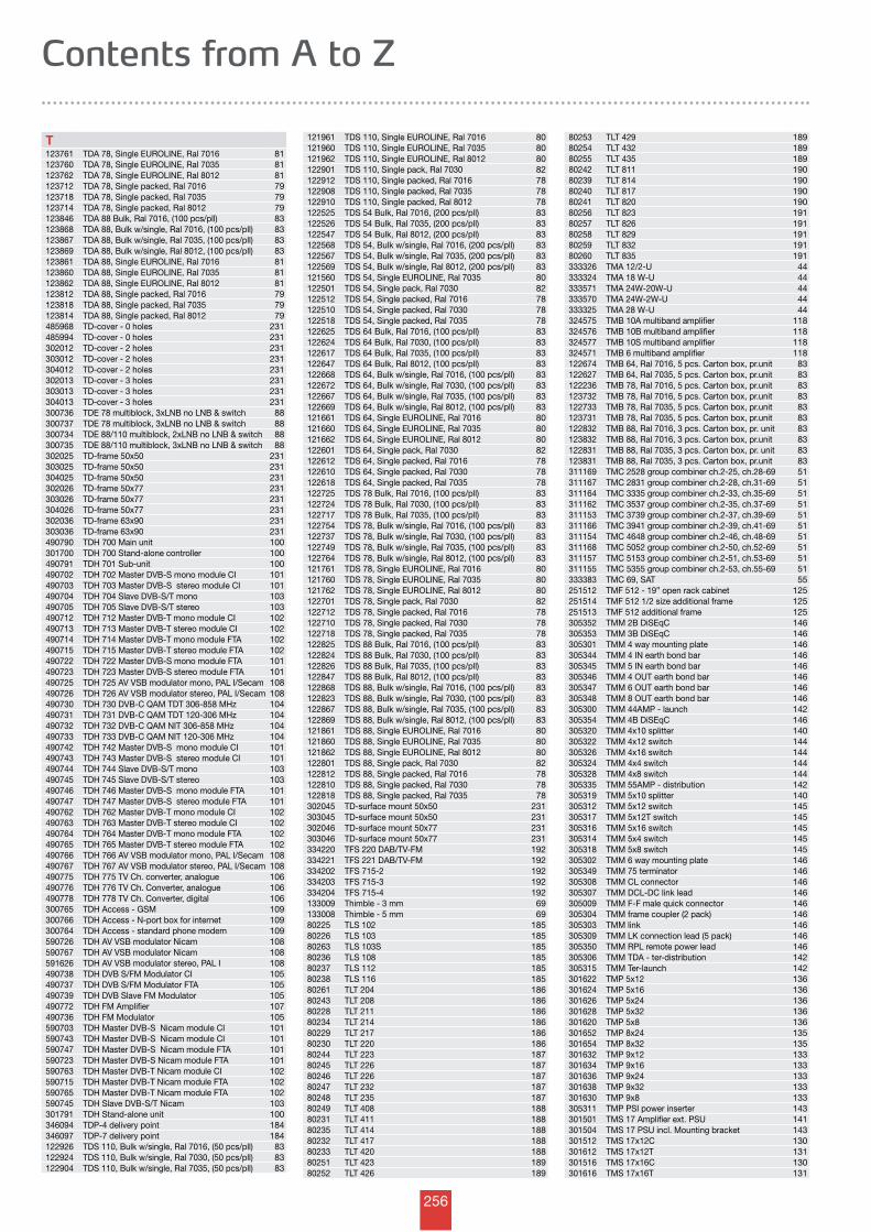
256
Contents from A to Z
T123761 TDA 78, Single EUROLINE, Ral 7016 81123760 TDA 78, Single EUROLINE, Ral 7035 81123762 TDA 78, Single EUROLINE, Ral 8012 81123712 TDA 78, Single packed, Ral 7016 79123718 TDA 78, Single packed, Ral 7035 79123714 TDA 78, Single packed, Ral 8012 79123846 TDA 88 Bulk, Ral 7016, (100 pcs/pll) 83123868 TDA 88, Bulk w/single, Ral 7016, (100 pcs/pll) 83123867 TDA 88, Bulk w/single, Ral 7035, (100 pcs/pll) 83123869 TDA 88, Bulk w/single, Ral 8012, (100 pcs/pll) 83123861 TDA 88, Single EUROLINE, Ral 7016 81123860 TDA 88, Single EUROLINE, Ral 7035 81123862 TDA 88, Single EUROLINE, Ral 8012 81123812 TDA 88, Single packed, Ral 7016 79123818 TDA 88, Single packed, Ral 7035 79123814 TDA 88, Single packed, Ral 8012 79485968 TD-cover - 0 holes 231485994 TD-cover - 0 holes 231302012 TD-cover - 2 holes 231303012 TD-cover - 2 holes 231304012 TD-cover - 2 holes 231302013 TD-cover - 3 holes 231303013 TD-cover - 3 holes 231304013 TD-cover - 3 holes 231300736 TDE 78 multiblock, 3xLNB no LNB & switch 88300737 TDE 78 multiblock, 3xLNB no LNB & switch 88300734 TDE 88/110 multiblock, 2xLNB no LNB & switch 88300735 TDE 88/110 multiblock, 3xLNB no LNB & switch 88302025 TD-frame 50x50 231303025 TD-frame 50x50 231304025 TD-frame 50x50 231302026 TD-frame 50x77 231303026 TD-frame 50x77 231304026 TD-frame 50x77 231302036 TD-frame 63x90 231303036 TD-frame 63x90 231490790 TDH 700 Main unit 100301700 TDH 700 Stand-alone controller 100490791 TDH 701 Sub-unit 100490702 TDH 702 Master DVB-S mono module CI 101490703 TDH 703 Master DVB-S stereo module CI 101490704 TDH 704 Slave DVB-S/T mono 103490705 TDH 705 Slave DVB-S/T stereo 103490712 TDH 712 Master DVB-T mono module CI 102490713 TDH 713 Master DVB-T stereo module CI 102490714 TDH 714 Master DVB-T mono module FTA 102490715 TDH 715 Master DVB-T stereo module FTA 102490722 TDH 722 Master DVB-S mono module FTA 101490723 TDH 723 Master DVB-S stereo module FTA 101490725 TDH 725 AV VSB modulator mono, PAL I/Secam 108490726 TDH 726 AV VSB modulator stereo, PAL I/Secam 108490730 TDH 730 DVB-C QAM TDT 306-858 MHz 104490731 TDH 731 DVB-C QAM TDT 120-306 MHz 104490732 TDH 732 DVB-C QAM NIT 306-858 MHz 104490733 TDH 733 DVB-C QAM NIT 120-306 MHz 104490742 TDH 742 Master DVB-S mono module CI 101490743 TDH 743 Master DVB-S stereo module CI 101490744 TDH 744 Slave DVB-S/T mono 103490745 TDH 745 Slave DVB-S/T stereo 103490746 TDH 746 Master DVB-S mono module FTA 101490747 TDH 747 Master DVB-S stereo module FTA 101490762 TDH 762 Master DVB-T mono module CI 102490763 TDH 763 Master DVB-T stereo module CI 102490764 TDH 764 Master DVB-T mono module FTA 102490765 TDH 765 Master DVB-T stereo module FTA 102490766 TDH 766 AV VSB modulator mono, PAL I/Secam 108490767 TDH 767 AV VSB modulator stereo, PAL I/Secam 108490775 TDH 775 TV Ch. converter, analogue 106490776 TDH 776 TV Ch. Converter, analogue 106490778 TDH 778 TV Ch. Converter, digital 106300765 TDH Access - GSM 109300766 TDH Access - N-port box for internet 109300764 TDH Access - standard phone modem 109590726 TDH AV VSB modulator Nicam 108590767 TDH AV VSB modulator Nicam 108591626 TDH AV VSB modulator stereo, PAL I 108490738 TDH DVB S/FM Modulator CI 105490737 TDH DVB S/FM Modulator FTA 105490739 TDH DVB Slave FM Modulator 105490772 TDH FM Amplifier 107490736 TDH FM Modulator 105590703 TDH Master DVB-S Nicam module CI 101590743 TDH Master DVB-S Nicam module CI 101590747 TDH Master DVB-S Nicam module FTA 101590723 TDH Master DVB-S Nicam module FTA 101590763 TDH Master DVB-T Nicam module CI 102590715 TDH Master DVB-T Nicam module FTA 102590765 TDH Master DVB-T Nicam module FTA 102590745 TDH Slave DVB-S/T Nicam 103301791 TDH Stand-alone unit 100346094 TDP-4 delivery point 184346097 TDP-7 delivery point 184122926 TDS 110, Bulk w/single, Ral 7016, (50 pcs/pll) 83122924 TDS 110, Bulk w/single, Ral 7030, (50 pcs/pll) 83122904 TDS 110, Bulk w/single, Ral 7035, (50 pcs/pll) 83
121961 TDS 110, Single EUROLINE, Ral 7016 80121960 TDS 110, Single EUROLINE, Ral 7035 80121962 TDS 110, Single EUROLINE, Ral 8012 80122901 TDS 110, Single pack, Ral 7030 82122912 TDS 110, Single packed, Ral 7016 78122908 TDS 110, Single packed, Ral 7035 78122910 TDS 110, Single packed, Ral 8012 78122525 TDS 54 Bulk, Ral 7016, (200 pcs/pll) 83122526 TDS 54 Bulk, Ral 7035, (200 pcs/pll) 83122547 TDS 54 Bulk, Ral 8012, (200 pcs/pll) 83122568 TDS 54, Bulk w/single, Ral 7016, (200 pcs/pll) 83122567 TDS 54, Bulk w/single, Ral 7035, (200 pcs/pll) 83122569 TDS 54, Bulk w/single, Ral 8012, (200 pcs/pll) 83121560 TDS 54, Single EUROLINE, Ral 7035 80122501 TDS 54, Single pack, Ral 7030 82122512 TDS 54, Single packed, Ral 7016 78122510 TDS 54, Single packed, Ral 7030 78122518 TDS 54, Single packed, Ral 7035 78122625 TDS 64 Bulk, Ral 7016, (100 pcs/pll) 83122624 TDS 64 Bulk, Ral 7030, (100 pcs/pll) 83122617 TDS 64 Bulk, Ral 7035, (100 pcs/pll) 83122647 TDS 64 Bulk, Ral 8012, (100 pcs/pll) 83122668 TDS 64, Bulk w/single, Ral 7016, (100 pcs/pll) 83122672 TDS 64, Bulk w/single, Ral 7030, (100 pcs/pll) 83122667 TDS 64, Bulk w/single, Ral 7035, (100 pcs/pll) 83122669 TDS 64, Bulk w/single, Ral 8012, (100 pcs/pll) 83121661 TDS 64, Single EUROLINE, Ral 7016 80121660 TDS 64, Single EUROLINE, Ral 7035 80121662 TDS 64, Single EUROLINE, Ral 8012 80122601 TDS 64, Single pack, Ral 7030 82122612 TDS 64, Single packed, Ral 7016 78122610 TDS 64, Single packed, Ral 7030 78122618 TDS 64, Single packed, Ral 7035 78122725 TDS 78 Bulk, Ral 7016, (100 pcs/pll) 83122724 TDS 78 Bulk, Ral 7030, (100 pcs/pll) 83122717 TDS 78 Bulk, Ral 7035, (100 pcs/pll) 83122754 TDS 78, Bulk w/single, Ral 7016, (100 pcs/pll) 83122737 TDS 78, Bulk w/single, Ral 7030, (100 pcs/pll) 83122749 TDS 78, Bulk w/single, Ral 7035, (100 pcs/pll) 83122764 TDS 78, Bulk w/single, Ral 8012, (100 pcs/pll) 83121761 TDS 78, Single EUROLINE, Ral 7016 80121760 TDS 78, Single EUROLINE, Ral 7035 80121762 TDS 78, Single EUROLINE, Ral 8012 80122701 TDS 78, Single pack, Ral 7030 82122712 TDS 78, Single packed, Ral 7016 78122710 TDS 78, Single packed, Ral 7030 78122718 TDS 78, Single packed, Ral 7035 78122825 TDS 88 Bulk, Ral 7016, (100 pcs/pll) 83122824 TDS 88 Bulk, Ral 7030, (100 pcs/pll) 83122826 TDS 88 Bulk, Ral 7035, (100 pcs/pll) 83122847 TDS 88 Bulk, Ral 8012, (100 pcs/pll) 83122868 TDS 88, Bulk w/single, Ral 7016, (100 pcs/pll) 83122823 TDS 88, Bulk w/single, Ral 7030, (100 pcs/pll) 83122867 TDS 88, Bulk w/single, Ral 7035, (100 pcs/pll) 83122869 TDS 88, Bulk w/single, Ral 8012, (100 pcs/pll) 83121861 TDS 88, Single EUROLINE, Ral 7016 80121860 TDS 88, Single EUROLINE, Ral 7035 80121862 TDS 88, Single EUROLINE, Ral 8012 80122801 TDS 88, Single pack, Ral 7030 82122812 TDS 88, Single packed, Ral 7016 78122810 TDS 88, Single packed, Ral 7030 78122818 TDS 88, Single packed, Ral 7035 78302045 TD-surface mount 50x50 231303045 TD-surface mount 50x50 231302046 TD-surface mount 50x77 231303046 TD-surface mount 50x77 231334220 TFS 220 DAB/TV-FM 192334221 TFS 221 DAB/TV-FM 192334202 TFS 715-2 192334203 TFS 715-3 192334204 TFS 715-4 192133009 Thimble - 3 mm 69133008 Thimble - 5 mm 6980225 TLS 102 18580226 TLS 103 18580263 TLS 103S 18580236 TLS 108 18580237 TLS 112 18580238 TLS 116 18580261 TLT 204 18680243 TLT 208 18680228 TLT 211 18680234 TLT 214 18680229 TLT 217 18680230 TLT 220 18680244 TLT 223 18780245 TLT 226 18780246 TLT 226 18780247 TLT 232 18780248 TLT 235 18780249 TLT 408 18880231 TLT 411 18880235 TLT 414 18880232 TLT 417 18880233 TLT 420 18880251 TLT 423 18980252 TLT 426 189
80253 TLT 429 18980254 TLT 432 18980255 TLT 435 18980242 TLT 811 19080239 TLT 814 19080240 TLT 817 19080241 TLT 820 19080256 TLT 823 19180257 TLT 826 19180258 TLT 829 19180259 TLT 832 19180260 TLT 835 191333326 TMA 12/2-U 44333324 TMA 18 W-U 44333571 TMA 24W-20W-U 44333570 TMA 24W-2W-U 44333325 TMA 28 W-U 44324575 TMB 10A multiband amplifier 118324576 TMB 10B multiband amplifier 118324577 TMB 10S multiband amplifier 118324571 TMB 6 multiband amplifier 118122674 TMB 64, Ral 7016, 5 pcs. Carton box, pr.unit 83122627 TMB 64, Ral 7035, 5 pcs. Carton box, pr.unit 83122236 TMB 78, Ral 7016, 5 pcs. Carton box, pr.unit 83123732 TMB 78, Ral 7016, 5 pcs. Carton box, pr.unit 83122733 TMB 78, Ral 7035, 5 pcs. Carton box, pr.unit 83123731 TMB 78, Ral 7035, 5 pcs. Carton box, pr.unit 83122832 TMB 88, Ral 7016, 3 pcs. Carton box, pr. unit 83123832 TMB 88, Ral 7016, 3 pcs. Carton box, pr.unit 83122831 TMB 88, Ral 7035, 3 pcs. Carton box, pr. unit 83123831 TMB 88, Ral 7035, 3 pcs. Carton box, pr.unit 83311169 TMC 2528 group combiner ch.2-25, ch.28-69 51311167 TMC 2831 group combiner ch.2-28, ch.31-69 51311164 TMC 3335 group combiner ch.2-33, ch.35-69 51311162 TMC 3537 group combiner ch.2-35, ch.37-69 51311153 TMC 3739 group combiner ch.2-37, ch.39-69 51311166 TMC 3941 group combiner ch.2-39, ch.41-69 51311154 TMC 4648 group combiner ch.2-46, ch.48-69 51311168 TMC 5052 group combiner ch.2-50, ch.52-69 51311157 TMC 5153 group combiner ch.2-51, ch.53-69 51311155 TMC 5355 group combiner ch.2-53, ch.55-69 51333383 TMC 69, SAT 55251512 TMF 512 - 19” open rack cabinet 125251514 TMF 512 1/2 size additional frame 125251513 TMF 512 additional frame 125305352 TMM 2B DiSEqC 146305353 TMM 3B DiSEqC 146305301 TMM 4 way mounting plate 146305344 TMM 4 IN earth bond bar 146305345 TMM 5 IN earth bond bar 146305346 TMM 4 OUT earth bond bar 146305347 TMM 6 OUT earth bond bar 146305348 TMM 8 OUT earth bond bar 146305300 TMM 44AMP - launch 142305354 TMM 4B DiSEqC 146305320 TMM 4x10 splitter 140305322 TMM 4x12 switch 144305326 TMM 4x16 switch 144305324 TMM 4x4 switch 144305328 TMM 4x8 switch 144305335 TMM 55AMP - distribution 142305319 TMM 5x10 splitter 140305312 TMM 5x12 switch 145305317 TMM 5x12T switch 145305316 TMM 5x16 switch 145305314 TMM 5x4 switch 145305318 TMM 5x8 switch 145305302 TMM 6 way mounting plate 146305349 TMM 75 terminator 146305308 TMM CL connector 146305307 TMM DCL-DC link lead 146305009 TMM F-F male quick connector 146305304 TMM frame coupler (2 pack) 146305303 TMM link 146305309 TMM LK connection lead (5 pack) 146305350 TMM RPL remote power lead 146305306 TMM TDA - ter-distribution 142305315 TMM Ter-launch 142301622 TMP 5x12 136301624 TMP 5x16 136301626 TMP 5x24 136301628 TMP 5x32 136301620 TMP 5x8 136301652 TMP 8x24 135301654 TMP 8x32 135301632 TMP 9x12 133301634 TMP 9x16 133301636 TMP 9x24 133301638 TMP 9x32 133301630 TMP 9x8 133305311 TMP PSI power inserter 143301501 TMS 17 Amplifier ext. PSU 141301504 TMS 17 PSU incl. Mounting bracket 143301512 TMS 17x12C 130301612 TMS 17x12T 131301516 TMS 17x16C 130301616 TMS 17x16T 131
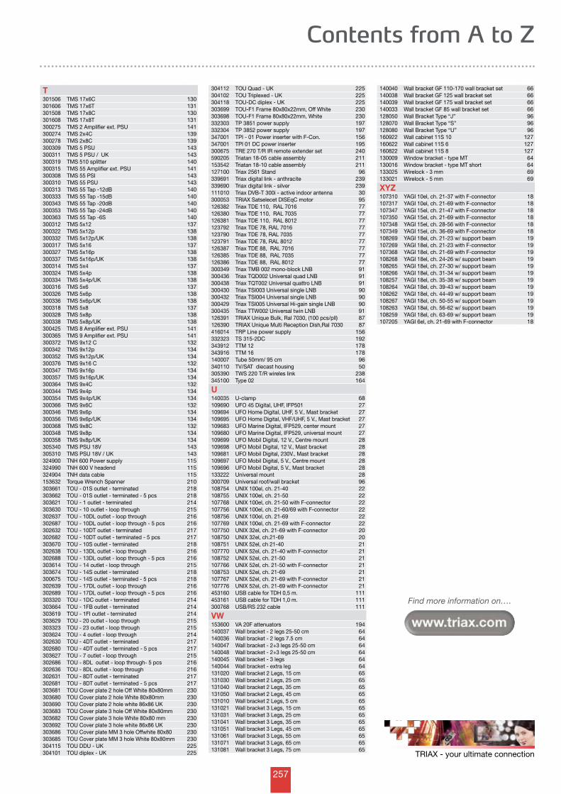
257
Find more information on….
TRIAX - your ultimate connection
Contents from A to Z
T301506 TMS 17x6C 130301606 TMS 17x6T 131301508 TMS 17x8C 130301608 TMS 17x8T 131300275 TMS 2 Amplifier ext. PSU 141300274 TMS 2x4C 139300278 TMS 2x8C 139300309 TMS 5 PSU 143300311 TMS 5 PSU / UK 143300319 TMS 510 splitter 140300315 TMS 55 Amplifier ext. PSU 141300308 TMS 55 PSI 143300310 TMS 55 PSU 143300313 TMS 55 Tap -12dB 140300333 TMS 55 Tap -15dB 140300343 TMS 55 Tap -20dB 140300353 TMS 55 Tap -24dB 140300363 TMS 55 Tap -6S 140300312 TMS 5x12 137300322 TMS 5x12p 138300332 TMS 5x12p/UK 138300317 TMS 5x16 137300327 TMS 5x16p 138300337 TMS 5x16p/UK 138300314 TMS 5x4 137300324 TMS 5x4p 138300334 TMS 5x4p/UK 138300316 TMS 5x6 137300326 TMS 5x6p 138300336 TMS 5x6p/UK 138300318 TMS 5x8 137300328 TMS 5x8p 138300338 TMS 5x8p/UK 138300425 TMS 8 Amplifier ext. PSU 141300365 TMS 9 Amplifier ext. PSU 141300372 TMS 9x12 C 132300342 TMS 9x12p 134300352 TMS 9x12p/UK 134300376 TMS 9x16 C 132300347 TMS 9x16p 134300357 TMS 9x16p/UK 134300364 TMS 9x4C 132300344 TMS 9x4p 134300354 TMS 9x4p/UK 134300366 TMS 9x6C 132300346 TMS 9x6p 134300356 TMS 9x6p/UK 134300368 TMS 9x8C 132300348 TMS 9x8p 134300358 TMS 9x8p/UK 134305340 TMS PSU 18V 143305310 TMS PSU 18V / UK 143324900 TNH 600 Power supply 115324990 TNH 600 V headend 115324904 TNH data cable 115153632 Torque Wrench Spanner 210303661 TOU - 01S outlet - terminated 218303662 TOU - 01S outlet - terminated - 5 pcs 218303621 TOU - 1 outlet - terminated 214303630 TOU - 10 outlet - loop through 215302637 TOU - 10DL outlet - loop through 216302687 TOU - 10DL outlet - loop through - 5 pcs 216302632 TOU - 10DT outlet - terminated 217302682 TOU - 10DT outlet - terminated - 5 pcs 217303670 TOU - 10S outlet - terminated 218302638 TOU - 13DL outlet - loop through 216302688 TOU - 13DL outlet - loop through - 5 pcs 216303614 TOU - 14 outlet - loop through 215303674 TOU - 14S outlet - terminated 218300675 TOU - 14S outlet - terminated - 5 pcs 218302639 TOU - 17DL outlet - loop through 216302689 TOU - 17DL outlet - loop through - 5 pcs 216303320 TOU - 1DC outlet - terminated 214303664 TOU - 1FB outlet - terminated 214303619 TOU - 1FI outlet - terminated 214303629 TOU - 20 outlet - loop through 215303323 TOU - 23 outlet - loop through 215303624 TOU - 4 outlet - loop through 214302630 TOU - 4DT outlet - terminated 217302680 TOU - 4DT outlet - terminated - 5 pcs 217303627 TOU - 7 outlet - loop through 215302686 TOU - 8DL outlet - loop through- 5 pcs 216302636 TOU - 8DL outlet - loop through 216302631 TOU - 8DT outlet - terminated 217302681 TOU - 8DT outlet - terminated - 5 pcs 217303681 TOU Cover plate 2 hole Off White 80x80mm 230303680 TOU Cover plate 2 hole White 80x80mm 230303690 TOU Cover plate 2 hole white 86x86 UK 230303683 TOU Cover plate 3 hole Off White 80x80mm 230303682 TOU Cover plate 3 hole White 80x80 mm 230303692 TOU Cover plate 3 hole white 86x86 UK 230303686 TOU Cover plate MM 3 hole Offwhite 80x80 230303685 TOU Cover plate MM 3 hole White 80x80mm 230304115 TOU DDU - UK 225304101 TOU diplex - UK 225
304112 TOU Quad - UK 225304102 TOU Triplexed - UK 225304118 TOU-DC diplex - UK 225303699 TOU-F1 Frame 80x80x22mm, Off White 230303698 TOU-F1 Frame 80x80x22mm, White 230332303 TP 3851 power supply 197332304 TP 3852 power supply 197347001 TPI - 01 Power inserter with F-Con. 156347001 TPI 01 DC power inserter 195300675 TRE 270 T/R IR remote extender set 240590205 Triatan 18-05 cable assembly 211153542 Triatan 18-10 cable assembly 211127100 Triax 2561 Stand 96339691 Triax digital link - anthracite 239339690 Triax digital link - silver 239111010 Triax DVB-T 300i - active indoor antenna 30300053 TRIAX Satselecet DISEqC motor 95126382 Triax TDE 110, RAL 7016 77126380 Triax TDE 110, RAL 7035 77126381 Triax TDE 110, RAL 8012 77123792 Triax TDE 78, RAL 7016 77123790 Triax TDE 78, RAL 7035 77123791 Triax TDE 78, RAL 8012 77126387 Triax TDE 88, RAL 7016 77126385 Triax TDE 88, RAL 7035 77126386 Triax TDE 88, RAL 8012 77300349 Triax TMB 002 mono-block LNB 91300436 Triax TQD002 Universal quad LNB 91300438 Triax TQT002 Universal quattro LNB 91300430 Triax TSI003 Universal single LNB 90300432 Triax TSI004 Universal single LNB 90300429 Triax TSI005 Universal Hi-gain single LNB 90300435 Triax TTW002 Universal twin LNB 91126391 TRIAX Unique Bulk, Ral 7030, (100 pcs/pll) 87126390 TRIAX Unique Multi Reception Dish,Ral 7030 87416014 TRP Line power supply 156332323 TS 315-2DC 192343912 TTM 12 178343916 TTM 16 178140007 Tube 50mm/ 95 cm 96340110 TV/SAT diecast housing 50305390 TWS 220 T/R wireles link 238345100 Type 02 164
U140035 U-clamp 68109690 UFO 45 Digital, UHF, IFP501 27109694 UFO Home Digital, UHF, 5 V., Mast bracket 27109695 UFO Home Digital, VHF/UHF, 5 V., Mast bracket 27109683 UFO Marine Digital, IFP529, center mount 27109680 UFO Marine Digital, IFP529, universal mount 27109699 UFO Mobil Digital, 12 V., Centre mount 28109698 UFO Mobil Digital, 12 V., Mast bracket 28109681 UFO Mobil Digital, 230V., Mast bracket 28109697 UFO Mobil Digital, 5 V., Centre mount 28109696 UFO Mobil Digital, 5 V., Mast bracket 28133222 Universal mount 28300709 Universal roof/wall bracket 96108754 UNIX 100el, ch. 21-40 22108755 UNIX 100el, ch. 21-50 22107768 UNIX 100el, ch. 21-50 with F-connector 22107756 UNIX 100el, ch. 21-60/69 with F-connector 22108756 UNIX 100el, ch. 21-69 22107769 UNIX 100el, ch. 21-69 with F-connector 22107750 UNIX 32el, ch. 21-69 with F-connector 20108750 UNIX 32el, ch.21-69 20108751 UNIX 52el, ch 21-40 21107770 UNIX 52el, ch. 21-40 with F-connector 21108752 UNIX 52el, ch. 21-50 21107766 UNIX 52el, ch. 21-50 with F-connector 21108753 UNIX 52el, ch. 21-69 21107767 UNIX 52el, ch. 21-69 with F-connector 21107776 UNIX 52el, ch. 21-69 with F-connector 21453160 USB cable for TDH 0,5 m. 111453161 USB cable for TDH 1,0 m. 111300768 USB/RS 232 cable 111
VW153600 VA 20F attenuators 194140037 Wall bracket - 2 legs 25-50 cm 64140036 Wall bracket - 2 legs 7.5 cm 64140047 Wall bracket - 2+3 legs 25-50 cm 64140048 Wall bracket - 2+3 legs 25-50 cm 64140045 Wall bracket - 3 legs 64140044 Wall bracket - extra leg 64131020 Wall bracket 2 Legs, 15 cm 65131030 Wall bracket 2 Legs, 25 cm 65131040 Wall bracket 2 Legs, 35 cm 65131050 Wall bracket 2 Legs, 45 cm 65131010 Wall bracket 2 Legs, 5 cm 65131021 Wall bracket 3 Legs, 15 cm 65131031 Wall bracket 3 Legs, 25 cm 65131041 Wall bracket 3 Legs, 35 cm 65131051 Wall bracket 3 Legs, 45 cm 65131061 Wall bracket 3 Legs, 55 cm 65131071 Wall bracket 3 Legs, 65 cm 65131081 Wall bracket 3 Legs, 75 cm 65
140040 Wall bracket GF 110-170 wall bracket set 66140038 Wall bracket GF 125 wall bracket set 66140039 Wall bracket GF 175 wall bracket set 66140033 Wall bracket GF 85 wall bracket set 66128050 Wall Bracket Type “J” 96128070 Wall Bracket Type “S” 96128080 Wall Bracket Type “U” 96160922 Wall cabinet 11S 10 127160622 Wall cabinet 11S 6 127160822 Wall cabinet 11S 8 127130009 Window bracket - type MT 64130016 Window bracket - type MT short 64133025 Wirelock - 3 mm 69133021 Wirelock - 5 mm 69
XYZ107310 YAGI 10el, ch. 21-37 with F-connector 18107317 YAGI 10el, ch. 21-69 with F-connector 18107347 YAGI 15el, ch. 21-47 with F-connector 18107350 YAGI 15el, ch. 21-69 with F-connector 18107348 YAGI 15el, ch. 28-56 with F-connector 18107349 YAGI 15el, ch. 36-69 with F-connector 18108269 YAGI 18el, ch. 21-23 w/ support beam 19107269 YAGI 18el, ch. 21-23 with F-connector 19107368 YAGI 18el, ch. 21-69 with F-connector 19108268 YAGI 18el, ch. 24-26 w/ support beam 19108265 YAGI 18el, ch. 27-30 w/ support beam 19108266 YAGI 18el, ch. 31-34 w/ support beam 19108257 YAGI 18el, ch. 35-38 w/ support beam 19108264 YAGI 18el, ch. 39-43 w/ support beam 19108262 YAGI 18el, ch. 44-49 w/ support beam 19108267 YAGI 18el, ch. 50-55 w/ support beam 19108263 YAGI 18el, ch. 56-62 w/ support beam 19108259 YAGI 18el, ch. 63-69 w/ support beam 19107205 YAGI 6el, ch. 21-69 with F-connector 18
258
General sales and delivery conditions
1. APPLICATIONAll sales of the seller’s products are made according to the following conditions which have preference to any stipulations laid down in the buyer’s order/ acceptance, including buyer’s general conditions, unless otherwise stated in a written agreement, and in that case with an exact indication of the points from which these sales and delivery conditions are deviating.
2. QUOTATION AND ORDER CONFIRMATION Quotations made by the seller are open for 30 days from the date of the offer, unless otherwise specified.
3. PRODUCT INFORMATIONInformation and Technical data on seller’s products stated in catalogues, leaflets and other written material are only to be considered as approxIMDte and not binding on seller, unless a written agreement explicitly states otherwise.
All drawings and technical specifications handed over to buyer prior to or after entering into an agreement remain seller’s property. No material must be used or copied by the buyer without the seller’s written permission, neither must it be reproduced, handed over nor brought to the knowledge of a third party for another purpose than the performance of the agreement made. Failing an agreement, all documentation handed over should be returned to seller, and also in that case no copying or general use of the material can be made, nor must it be brought to the knowledge of a third party.
The seller is not responsible for the buyer’s selection of the product, including compatibility of the product, its use and results, unless the contract explicitly refers to these.
The seller undertakes no responsibility for the buyer’s selection of potential supplementary equipment and service requested for use with the product as well as application and results of same.
The seller reserves the right to modify his products without notice as far as such modifications do not cause major restrictions of the applications.
4. PRICE ALTERATIONSThe seller reserves the right to alter prices in case of major changes of rates of exchange, increased prices for raw materials, political events or other conditions which the seller cannot control, unless a written agreement states that the seller is not entitled to make such reservation.
5. PASSING THE RISKThe risk for the product is passed upon delivery, unless otherwise agreed in writing. Such agreements are made in accordance with Incoterms 90 termi nology.
6. TIME OF DELIVERY; DELAYSThe agreed time of delivery is only approx imdte and subject to full approval of the contents of the agreement, for instance accepted drawings.
The seller is never responsible for delays, unless such delays are owing to gross negligence on his part.The seller is never responsible for operational losses, loss of profit, loss on goods kept in stock, loss caused by delayed building activities or other contract work or any other direct or indirect loss or direct or indirect costs caused by delayed deliveries.
If delays should occur, and if, at the buyer’s request, the seller cannot state a delivery period, the buyer has the right to cancel the order and demand re imbursement of potential (pre)payment, provided that the products have not been made especially to the customer’s specifications.
Above statement defines the seller’s maximum responsibility in relation to delays.
7. PAYMENT, RETENTION OF OWNERSHIP UNTIL PAYMENT IS MADEThe seller reserves for himself the right of ownership until the agreed price has been paid.
In that case it is the buyer’s duty to take out an insurance on the goods against any damage from the date of the passing of the risk until the agreed price has been paid. The insurance should cover full and new value of the goods in question.
Until close to the date of delivery, the seller has a right to demand, and the customer is bound to give a banker’s guarantee payable on demand in an acknowledged bank for the total purchase sum including costs and outlays. As far as mounting and servicing is concerned, the seller is justified to demand at any time, and the buyer is liable to give a banker’s guarantee payable on demand in an acknowledged bank for the agreed payment or partial payment, including costs and outlays, if any.
For delivery of products that should form part of another product, the seller is entitled to demand at any time, and the buyer is liable to give a banker’s guarantee payable on demand in an acknowledged bank for an amount corresponding to the purchase sum for the parts entered at the time in question, but not yet paid. If the buyer does not give such a banker’s guarantee on request, the seller is entitled to consider the agreement(s) non-fulfilled, wholly or partly, and the seller is entitled to claim delivery of products that have not been used and not paid. The buyer is thus unable to work with or otherwise use such products.
Payment has to be made at the time stated in the quotation or the order con firmation. If the buyer does not pay in due time, the seller reserves for himself the right to charge 2% interest on late payments for each new month. The same interest is charged if a respite has been granted. The buyer is not entitled to keep back payments or to set off against asserted claims that have not been accepted by the seller. If the buyer does not want to receive the lot at the time agreed, he is obliged to pay as if delivery had been made according to the agreement.
8. PACKING Disposable packing has been included in the price and will not be refunded in case of a possible returning.
Multi-way packing will be charged and credited to the customer in case of prompt and safe return, carriage-paid.
The buyer shall reimburse the seller for any costs or charges for which the seller becomes legally liable in respect of the removal and disposal of packaging materials.
9. TOOLS Applied tools which have been debited to the buyer wholly or in part, according to agreement, remain in the seller’s warehouse, but are not delivered. The seller takes care of the proper maintenance of these tools. If such tools are not used for 3 years, the seller is no longer bound to keep and maintain them.
No liability rests with the seller for tools lent by the buyer, if they have not been used for 2 years and not been demanded by then.
10. PROPERTY/INCORPOREAL RIGHTSThe buyer does not acquire property and/or inventor’s rights / other incorporeal rights to any computer programmes used for the product, nor any drawings, design, technical solutions etc. whether individually made for the buyer on his account or not, since the buyer is only entitled to use such material in relation to the agreed application of the product.
11. RESPONSIBILITY FOR VIOLATION OF PATENT AND OTHER INCORPOREAL RIGHTSIf there should be a risk, or if it is asserted that the product infringes a patent or another incorporeal right, the buyer accepts that, at his own option, the seller is either allowed by the proper party to continued use or he changes or replaces the product, so that it no longer gives rise to an infringement.
If none of these alternatives can be achieved on terms that the seller finds reasonable, he can claim that the buyer refrains from using the product against an allowance from the seller corresponding to the value of the product after depreciation with equal amounts every year compared to the technical and economical life of the product.
The size of such an allowance is not dependent on the question whether the product is integrated into another product or a building etc., and it is not influenced by the loss which it and/or discontinuance of use might cause the buyer.
In case of resale of the product, the buyer is liable to include an identical stipulation in the agreement between buyer and buyer’s customer, including instruct the customer to include an identical stipulation for the customer’s possible resale.
The seller’s maximum responsibilities as to any potential infringement of the patent or another incorporeal right are defined above.
259
General sales and delivery conditions
The information contained in this catalogue was to the best of the knowledge of Triax, correct at the time of publication.Triax reserves the right, without prior notice, to discontinue products or to make design changes as part of its continuous programme of product improvement.Triax will not accept responsability for damage, injury, loss or expense resulting from any error or omissions.
12. COMPLAINTSImmediately on receipt and prior to taking the products into use, the buyer should inspect the goods supplied to ensure that there are no shortcomings and that the correct quantity has been supplied.
Complaints of defects which have been found or should have been found at a general inspection must be made at once and not later than 8 days after receipt of the products. If the complaint is not made within the time limit stated, the buyer loses his right to put forward a claim.
Complaints of discrepancies in quantity and damages to the product should be made immediately to the carrier, if any, and to the seller. Otherwise, the buyer loses his right to complain of such faults.
13. RESPONSIBILITY FOR SHORTCOMINGSProvided that the agreed terms of payment are kept, and that complaints are made in due time, the seller will remedy any shortcomings that turn up during a period from 12 months from the delivery date. The responsibility does not comprise deficiencies caused by factors arisen after the risk has passed over to the buyer.
Remedy is only made by adjustment, repair or replacement of (parts of) the product or its com-ponents according to the seller’s option. Wages paid for dismounting and mounting will not be refunded. If dismounting and mounting should af-fect more than the product, such work and costs are irrelevant to the seller as well. The buyer has to send the seller a written complaint with details of the deficiency without undue delay. The complaint should be made immediately, if there is reason to believe that damages might be involved. If the buyer does not advise the seller of a deficiency within the time limit stated, the buyer will lose his right to make a claim.
Return of repaired parts or return of the product is paid by the seller who takes over replaced parts, if any. Unless otherwise agreed, the buyer will pay such additional costs that may arise if the product is situated at another place than the destination stated in the agreement, or, failing such information, the place of delivery.
If the product has been changed or someone else than the seller or a repair man appointed by the seller has tried to repair the product, or if the product has been subject to damages or used for unfit purposes, or if installation, operation and maintenance are not in compliance with the seller’s stipulations, the seller can refuse to remedy the deficiency free of charge.
Deficiencies caused by conditions for which the buyer or someone else is responsible, or which are not announced until after expiration of the remedying period, are not the seller’s business.
The seller’s responsibility does not include deficiencies arisen in materials provided by the customer or by a co-producer/supplier appointed by the customer or in constructions ordered or specified by him. If the seller does not meet his obligations within a reasonable time, the buyer can claim a proportional reduction of the purchase sum, but not more than 15% of the agreed purchase sum. In case of a vital deficiency, the buyer can cancel the agreement by a written notice to the seller, at the same time demanding compensation for his loss, i.e. max. 15% of the agreed purchase sum.
Above conditions are the seller’s maximum obligations concerning shortcomings. So the seller is neither responsible for direct nor indirect losses, including operational losses, loss of profit as well as costs or damages etc.
14. LIABILITY FOR CAUSING DAMAGES (PRODUCT LIABILITY)The seller is responsible for personal injuries according to the legislation concerning product liability.
The seller is not responsible for damages to real and personal property which occurs while the product is in the buyer’s possession. Nor is the seller responsible for damages to products made by the buyer or products comprising such parts. Furthermore, the seller is only responsible for damages to real and personal property, if it can be proved that the damage is caused by mistakes or negligence made by the seller or others whom the seller is responsible for.
The seller is not responsible for operational losses, loss of profit or other indirect losses.
If a product liability towards a third party has been imposed on the seller, the buyer is committed to indemnify the seller to the same degree as the seller’s responsibility stated in the three previous paragraphs.These limitations of the seller’s responsibility are not valid, if the seller has shown gross negligence.
If the third party claims compensation from one of the parties in accordance with this point, he should advise the other party immediately.
The buyer is bound to let the court or arbitration tribunal bring an action against him which deals with claims made against the seller for damages assertedly caused by the product.
15. FORCE MAJEURE
The seller’s obligations are suspended and can be dropped when missing fulfilment is owing to conditions beyond the seller’s control.
16. CONSUMERS’ PURCHASES IN DENMARKFor consumers’ purchases in Denmark the stipulations laid down in the Sale of Goods Act take precedence over these sales and delivery terms.
17. VENUE AND LAWAny dispute arising out of the contract shall be settled before a Danish court. The venue is „SØ- og Handelsretten“ in Copenhagen. However, the seller is entitled to demand arbitration according to the general rules of the Danish court. The Court of Arbitration is set up in Copenhagen. Settlement through arbitration does not exclude the possibility of an injunction or that other preliminary remedies can be carried through at the relevant revenue.
260
TRIAX A/S Bjørnkærvej 3 • DK-8783 Hornsyld +45 76 82 22 00 • +45 75 68 79 66 mail: [email protected] • www.triax.com
Your ultimate connectionTriax offer you insight, experience and a wide range of solutions
Find more information on….
Triax-Hirschmann Austria Empfangstechnik GmbHOberer Paspelsweg 6-86830 Rankweil - AustriaTel.: +43 55 22 307 0Fax: +43 55 22 307 394e-mail: [email protected]: www.hirschmann-austria.at
Triax FinlandMalminkaari 23 BFIN-00 700 HelsinkiFinlandTel: +358 9 34 78 470Fax: +358 9 34 78 4710e-mail: [email protected]: www.triax.fi
Triax Sárl13 rue du Chemin de FerZAC Lampertheim - CedexF - 67451 Mundolsheim CedexFranceTel: +33 38 81 80 909 Fax: +33 38 81 80 900e-mail: [email protected]: www.triax.fr
Triax-Hirschmann Multimedia GmbHKarl-Benz-Strasse 1072124 PliezhausenGermanyTel.: +49 7127 92 34 0Fax: +49 7127 92 34 10e-mail: [email protected] web: www.triax-hirschmann.com
Triax-Hirschmann Multimédia Electronics Kft.Rokolya u. 1-131131 BudapestHungaryTel.: +36 1 349 4199Fax: +36 1 329 8453e-mail: [email protected]: www.hirschmann-multimedia.hu
Triax-Hirschmann Multimeida Espãna S.L.N.I.F. B 28257848C/ Ingeniero Torres Quevedo, No 20Poligono Fin de Semana28022Madrid•SpainTel.: +34 91 74 828 36Fax: +34 91 32 961 47e-Mail: [email protected]: www.hirschmann.es
Triax Svenska ABSvedengatan 9S-582 73 LinköpingSwedenTel: +46 13 14 41 14Fax: +46 13 14 41 13e-mail: [email protected]: www.triax.se
Triax UKAbergorki Industrial EstateTreorchy - South Wales CF42 6DLUnited KingdomTel: +44 14 43 77 89 08 Fax: +44 14 43 77 77 79e-mail: [email protected]: www.triax.co.uk
Triax Middle EastPO Box 18351 - DubaiUnited Arab EmiratesTel: +971 4 887 3100Fax: +971 4 887 3101e-mail: [email protected]: www.triax.com
Dealer:
Aerials | Dishes | Receivers | Headends | Multi switches | Amplifiers | Outlets | Home accessories | Fibre cabinets | Enclosures
Art. No. 891407AK.452.1.02•Producedin2008All specification in this catalogue subject to change without notice
TriaxMarketing•©2005TheTriaxGroupAll rights reserved. Use of this material signifies your agreement to the terms of use.
The Triax Group is among the leaders within 2 business areas:• Triax Multimedia - Reception, distribution and storage of video, audio and data• Triax Cabinets - Protection of network equipment
TRIAX was founded in Denmark, Europe in 1949 and has kept growing ever since. 750 employees across the globe generate sales of 170 mill.€.We manufacture in Europe and China. We service our customers globally through 10 own companies and a growing net of distributors.
The Triax Group is a part of Nielsen & Nielsen Holding A/S which is the mother company in an international Danish company and employs more than 2400 employees in 37 companies.


