Embed Size (px)
Citation preview

Optics Communications 97 (1993) 115-129 North-Holland
OPTICS COMMUNICATIONS
Full length article
Triplator - optical signal processor based on rotational shearing interferometer
Joseph Rosen Rome Laboratory, Optical Signal Processing Branch/EROP, Hanscom AFB, MA O1731-5000, USA
and
Joseph Shamir Department of Electrical Engineering, Technion - Israel Institute of Technology, Haifa 32000, Israel
Received 25 June 1992; revised manuscript received 30 September 1992
A new integral transform involving three functions, a triplation, is introduced and its optical implementation is demonstrated. The optical system is based on a rotational shearing interferometer illuminated by partially coherent light. The triplation opera- tion is analyzed theoretically and some of its possible applications are discussed.
1. Introduction
In a recent publication [ 1 ] a generalized interferometric signal processor was introduced. In this processor a Fourier hologram is recorded by a rotational shearing interferometer and reconstructed by a conventional coherent 2-f optical Fourier transform (FT) configuration. It has been shown that a nonconventional processor could be obtained which involved three arbitrary complex functions. In some special cases and under various conditions, the system becomes an efficient image processor for specific tasks. For instance, the system can be used as a joint transform correlator (JTC) [2] illuminated by spatially incoherent light. In this paper we con- sider more extensively the case of the generalized processor from a theoretical point of view and demonstrate its operation experimentally. In the general case, three functions may be involved in some mathematical op- eration, which can be degenerated to more familiar operations, like convolution or multiplication between two functions. The initial goal of this work was to investigate various effects and processes that were discovered during previous work. One of these was the implementation of some unusual mathematical transformation with a slightly modified rotational shearing interferometer. The main purpose of this paper is to introduce this trans- form, and to consider its principal properties. Although the full merits of this transformation are not clear yet, some possible application will be briefly discussed and summarized in the conclusions. One particularly in- teresting application is described in sec. 4 while some special cases are considered in sec. 6. Preliminary ex- perimental results are given in sec. 5. We start the analysis with a description of the optical system, which ex- ecutes this processing.
2. The optical system
The optical system is composed of a rotational shearing interferometer illuminated by a spatially incoherent quasi-monochromatic light source [ 3 ], as shown in fig. I. Three functions are involved in the process. Two
0030-4018/93/$06.00 © 1993 Elsevier Science Publishers B.V. All rights reserved. 115

Volume 97, number 1,2 OPTICS COMMUNICATIONS 1 March 1993
INCOHEREN1 SOURCE
Ga( t l ) L 1 B S g2 ( r )
N I ROTATOR] P,
I ~.- f -,.Wl
\ M \
gt(r) La I
0 !
fa
B8
A
I PLANE ~ P4 WAVE
I I fa ~ f3 ~!~"~J
Fig. l. Rotal Lonal sheafing interferometer which is designed to perform the triplation.
fb
of them, g~ (r) and g2(r), ma,. be general complex functions placed in the input planes, P2, of the two inter- ferometer channels. The third : unction, Ga (~), is the intensity distribution of a spatially incoherent light source in plane P~, and is therefore r ,'stricted to positive values. Since plane Pa is in the focal plane of the lenses La and Lb, it is considered as a F ~urier plane related to plane P2. In one channel of the interferometer there are two periscopes [ 4 ], that serve to rotate the light distributions in the two channels with respect to each other, by an angle 7t. Every point i n he source generates a plane wave of relative amplitude ~ propagating at an angle sin-~ (~/f~) in one cl annel and sin-I ( - ~/f~ ) in the other, relative to the optical axis. These planes waves are multiplied by g~ (r) n one channel, and by g2(r) in the other. The overall intensity distribution over plane Pa is obtained by a cohe] mt superposition of the complex amplitudes form each source point propagated through the two channels and a summation over all the independent source points:
+ ~ d 2 r ~ e x p ( i ~ f ~ . r ) g 2 ( r ) e x p ( _ . 2 ~ t ,j2 " ' g P ' r ) l '
R
(1)
where ,~ and R are the apertu: e areas at planes P~ and P2, respectively; ~, r and p are the position vectors at planes P~, P2 and P3, respecti~ ely; f~, fa and fb are the focal lengths of lenses L~, La and Lb, respectively. After some algebraic procedures we obtain,
116

, , L : F . , 1 ; t ~ [ ] ~ t L:
Volume 97, number 1,2 OPTICS COMMUNICATIONS 1 March 1993
I(p) =
R
R
R
where,
gl (r)gT(r')g3(r-r' )exp I- ' l ~-~p.21r ~r-r" ' )] d2rd2r ' RR
gE(r)g~(r' )gs(-r+r')expl - .l_~bp.(r_r , 2 t r )] d2r d2r , R
gl(r)g~(r' )g3(r+r' ) expl-i 2-~ff p" ~ - ~)l d2rd2r'
g,(r' )g2(r)g3(-r-r' ) exp[-i 2-~ff p" ~r - ~)]d2rd2r ' ,
m general, g3 is a complex function equal to a scaled inverse FT of G3:
(2)
• 2~t
This relation is the well known Van Cittert-Zernike theorem [ 5 ] with g3 considered as the mutual coherence function between two points separated by a distance x in plane P2.
The intensity distribution given by eq. ( 1 ) is recorded as a transparency, and then displayed in the input plane of a conventional coherent 2-f system, equipped by a lens L3 with focal length f3. The output distribution, c(~), at plane P4 (5 denotes the coordinate of plane P4) is obtained by performing a FT (with the scale factor (2f3) - l ) on I(p) given by eq. (2):
c(r)=ga ~ O .f g'(r)g' (r- ~3 ~ d2r+ g3 ( - ~ r) .r g2(r)g' (r- ~ ~ d2r R R
. A L . +
(4)
The first two terms, located around the origin, can not be separated from each other and thus are of no interest here. We shall mainly be concerned with the other two terms which can be spatially isolated transversally, by introducing a linear phase function, or longitudinally, by using quadratic phase functions [ 1 ].
The third and the fourth terms represent a new kind of integral transform which we shall call triplation since it involves three functions. All three functions contained in the third term ofeq. (4) may be complex functions, with the restriction that the FT of g3 (r), G3(~) should be a positive valued function.
3. The triplation operation
We define the triplation operation by the relation,
c(s) =- <(g~, g2, ga )) ~ = ~ g, (x)g2(x-s)ga(x-as-b ) dx . (5)
It is easy to show that the triplation is the distribution along the line t=as+b in the triple correlation domain, where the triple correlation is defined by [ 6 ]
117

FULL LENGTH ARTICLE
Volume 97, number 1,2 OPTICS COMMUNICATIONS 1 March 1993
c(s, t) = ; g, (x)g2(x-s)g3( - t ) dr' . (6)
To see the connection betwee these definitions and the optical result, we rewrite the third and the fourth terms of eq. (4), with scaled versk ~s of the various functions
¢3 ($)---~ ~ gl (r)g~(r--$)g3 (r fb s)d2r f - ~ , R
c4(i) = J" g2 (r)o~T (r-$)~3 ( f ~ ~ d 2 r r - A +A ] ' R
(7)
where
¢gl(r)=g,~flr ) , g2(¥)--~g2
Obviously, the two terms of e (a, b) = ( f J (f~ +fb), 0), respq Fourier lenses produces the d I is the identity matrix, b= (C between three 2D functions.' scan all slope values by comp in each channel, that can be i focal lengths ratio) and than of the three functions within
The spectral distribution ol of a triplation is a triplation tc
1 "~{ <<g''g2'g3>> ba} = ~ <<'
where G~ b) (U) ---- exp ( - i2ttbt erator defined by the relation crates to the conventional cor using the convolution theoreI triplation. Therefore, the opt:
Using the above definition plane P4, given in eq. (4), ce
c(¢) =g3(¢)g, (~)*g, (~) +g3(
+ ((g~(r), g'~(r), ~[2]g30
-----g3(P) f gl (r)gT(r-P) d 2,
R
+ f g~ (r)g~(r-P)g3(2r-i R
~ r ~ 3 ( r ) = g 3 r , ' $=f3 f33
• (7) are triplation distributions with parameters: (a, b) = (fb/(f, +fb), 0), and :tively. In other words, changing the ratio between the focal distances of the two ~tributions over planes, each one represented by the equation t= ala+b, where 0) and a = (fb/(f~+fb) ), in the four dimensional triple correlation distribution a cover the whole triple-correlation domain by triplation operations we have to nsating for the scale changes• One way to do this is by a proper imaging system Ldependently varied. Alternatively, one may choose a single slope value (single
gradually the parameter b. Changing b can be easily achieved by shifting one ts plane. the triplation is derived in the appendix. It is shown that the Fourier transform ), which operates on the scaled Fourier transform of the original three functions.
I, ~ G~ b), ~ G2>>°/,, a#0, I, (8)
, G3(u), G{s are the Fourier transforms of the g{s and ¢'[d] is the scaling op- :[d] G(u) = G(du). For the special cases, a=O, or a= I, the triplation degen- flation integral. However, while the convolution integral can be easily evaluated , eq. (8) indicates that such a fast procedure is not applicable for the complete 'al implementation of the triplation has an additional value. for the special case where fs =f, =fb =f the complex amplitude distribution in t be rewritten in the form,
- P)g2(P)*g2 (P)
, )) °/2 + ((g2(r), gT(r), ~ [ -2]g3(r ) )) °/2
÷gs(-P) I g2(r)g~(r-P) d2r R
g2(r)gT(r-P)gs( - 2r+ P) d2r, (9) d2r+ R
where * denotes correlation. "ollowing eqs• (8) and (9), the intensity distribution in plane P3, given in eq. ( 1 ), can be rewritten in the 1 , re
118

Volume 97, number 1,2 OPTICS COMMUNICATIONS 1 March 1993
l(u) = G3(I~) * I GI (u) 12+G3(-•) * I G2(n) [2
+ (( GI (u), G 3 (-u), G~ (-u) )) o + ((G2(u), G3 (lu), GT(-u) )> o
= ~ G3(u')IGt(u-u')I 2d2u'+ ~ G3(-u')IG2(u-u')I 2d2u'
G, (u')Ga(u-u' )G'~(2u-u') d2u ' + j" G2(u' )Ga(u' -u)GT(2u-u') d2u ' , (10) +
where * is the convolution sign, and u is equal to p/2f. As we see from eqs. (10) and (9), the optical system generates now the special triplation with (a, b )= (1/2, 0) in the output reconstruction plane and (a, b ) = (2, 0) in the Fourier plane.
4 . T r i p l a t o r a s a s i g n a l p r o c e s s i n g s y s t e m
To investigate an interesting possible application of the triplator we define a system by a characteristic func- tion, h(x), which transforms an input signal g(x) to an output o(x' ) according to the relation,
(x x) o ( x ' ) = g ~ g* T h(x)dx. (11)
This output result is directly obtained for 2D functions from the third term of eq. (9) if we set g2(r)= gl ( - r ) =g( r ) , and the integration variable is changed properly. In other words, the proposed optical system implements the signal processor as defined by eq. ( 11 ).
Although the triplation, in the form ofeq. ( 11 ), is not linear with respect to the input function, g, it maintains some characteristics of linearity, which we shall call weak linearity (WL), which has practical significance for signal processing. The WL operation is defined for a set of functions gi(x) and an additional function h(x), all having finite extent. If the separation among the functions g~(x) is large enough so that h(x) can be placed between any two input functions g~(x)'s without overlap, an operation Ae is defined as WL operation if the relation,
Se{~ A,g,(x-d~)}= ~ Aa{A,g~(x-d,)}, (12)
is satisfied with d~ being the distance of gi(x) from the origin (A:s are constants). It is easy to show that triplation, as defined in eq. ( 11 ), is a WL operation and also shift invariant.
t
- • A * *
i : x + x ) ( x ) . . x - +d, h(x)dx- - ~ IA,12o,(x'-2dD (13) = ~i AigiL-"'-~-d, Aig, ~ i '
where oi(x' ) is defined in eq. ( 11 ) for the ith input, and crossterms were dropped by the non-overlapping condition. Since in many cases practical signals satisfy the conditions for WL operation, the triplation trans- form may prove quite useful for signal processing applications. An interesting example is pattern recognition under certain conditions.
A substantial difference exists between correlation and triplation. In the former, the extent of non-zero values in the output is the sum of the extent of the input function plus the extent of the system impulse response, h (x). In the latter, the extent is twice that of the input function and does not depend on h (x). This property
119

FULL LENGTH ARTICLE
Volume 97, number 1,2 OPTICS COMMUNICATIONS 1 March 1993
may be useful for cases when the impulse response function is wider than the input signal. In many cases of pattern r¢ ;ognition algorithms [ 7 ] the impulse response function is wider than some of
the objects in the training set. i {owever, in these algorithms the meaningful part of the output result is the value of the correlation peak. The u ual design goal of these pattern recognition systems is to obtain high and sharp correlation peaks, indicating r :cognition, and object location. The following simple example demonstrates the
O~
Z.5
2.0
1.0
0.5
0 , 0 . .
0
(a)
i
2 0 0 4 0 0 6 0 0 8 0 0 1 0 0 0 2 0 0
X
J=
-0:
1 . 5 (~))
1.0
0.5
0.0--
i
SDF I I I I I
J L I I L
40O
i i i i i , , i , i i i i i i I i i i
2 0 0 6 0 0 ~ , 0 0 1 0 0 0 1 2 0 0
X
Fig. 2. Comparison of signal matchfl g operation between a conventional correlator and the triplator. (a) The input signals to both system. (b) The SDF, calculated to id :ntify the tall rectangle. (c) The correlation result between the input signals and the SDF. (d) The triplation result obtained with the san e input signals and SDF.
120

H~tL t E f l L ~ l t l ~,HII~,L ~
Volume 97, number 1,2 OPTICS COMMUNICATIONS 1 March 1993
superior p e r f o r m a n c e of the triplator over the conventional correlator with respect to correlation peak sharpness. Let the two rectangles, shown in fig. 2a, be two 1D signals in a given training set. Assume that the aim is
to identify the higher rectangle using a synthetic discriminant function (SDF) [8] as shown in fig. 2b. The conventional correlation result between the SDF and the input signal is given in fig. 2c. Taking the same SDF for h(x) and performing a triplation on the same input function generated the output distribution shown in fig. 2d. Although both processes detected the higher rectangle, the triplation peak is much narrower. Note that
1.2
1.0
0.8
0.4
0"2 I
0,0 ,
0
1.2 (d)
1.0
0.8
~6.0.0
0.4
C o r r e l a t i o n r e s u l t I I I I I
I
200 400 @00 BOO 1000 1200 x 1
T r i p l a t i o n r e s u l t i i i i
0 200 400 600 800 1000 1200 xl
Fig. 2. (Continued.)
121

Volume 97, number I ,Z OPTICS COMMUNICATIONS
the triplation operation prod ted an output distribution with a separation between the two cross-triplations, twice as large as that betwee]’ the two crosscorrelation peaks. This makes the effective width of the triplation peak narrower by an additio al factor of two. It is expected that filters prepared for triplation will perform even better, but this subject I already outside the scope of this paper.
5. Experimental results
To demonstrate the actual I peration of an optical triplator some preliminary experiments were performed with some of the results showi: in figs. 3-5. In these illustrations the input masks are the same for both channels, g(r)=g,(r)=gz( -r), and thi two FI lenses are identical. As the input function we used a small section from a resolution chart including tl, -ee vertical lines and three horizontal lines. In the first experiment there was no source mask after the diffuse1 thus G3 could be considered as a unit function. Figure 3a shows the intensity distribution over plane P,. T: e four different terms of eq. ( 10) cannot be spatially separated, therefore the triplation distribution is not c stinguishable. However, since g(r) is shifted from the origin by some distance, the triplation terms in plane I .,, given in eq. (9), are transversally separated. In order to see it we displayed the distribution of fig. 3a on a iquid crystal television (LCTV ) SLM and illuminated it by a plane wave through a 2-f system. One such tripla’. on distribution, obtained in the first diffraction order, is shown in fig. 3b. The result is the reconstruction of’ ;he input mask, lg( r) I*, as expected when g3( r) =6(r). In the second example we inserted a coarse grating i Imediately after the diffuser. The source mask may be expressed, this time, as
G,(&, (,)= C rect n
q’ .’
where the width, Af, Id, is app I distribution, I(U) is shown iti This bias distribution is equa other was blocked. The subtri tribution of fig. 4b on the SLl! pattern shown in fig. 4c. The reconstruction along the x ax
1 March 1993
7 (14)
jximately equal to the width of a single line in the input mask, g(r). The spectral fig. 4a, while fig. 4b depicts the same spectrum after subtracting the bias term. to the two first terms of eq. ( 10) were recorded from each channel while the
ction was performed digitally between the different frames. Displaying the dis- : and performing the Fourier transform, yields, in the first diffraction order, the *esult is a blurring of the input transparency along the y axis, and a reasonable
Fig. 3. Experimental results of the op ical system obtained without source mask and with a small section of a bar chart as the input masks. (a) The intensity distribution over F ane PS. (b ) The triplation distribution measured in a part of plane P4.
122

k~JLl [ E r i b l t l ~.I-.~IIUIL
Volume 97, number 1,2 OPTICS COMMUNICATIONS 1 March 1993
Fig. 4. Experimental results of the optical system obtained with a centered grating as a source mask and with the same input masks as in fig. 3. (a) The intensity distribution over plane P3. (b) The intensity distribution displayed on the SLM, after subtracting the bias terms. (c) The triplation distribution measured in a part of the plane P4.
Fig. 5. Experimental results of the optical system obtained with a shifted grating as a source mask and with the same input masks as in fig. 3. (a) The intensity distribution over the plane P3. (b) The intensity distribution displayed on the SLM, after subtract- ing the bias terms. (c) The triplation distribution measured in a part of the plane P4.
123
Volume 97, number 1,2 OPTICS COMMUNICATIONS 1 March 1993
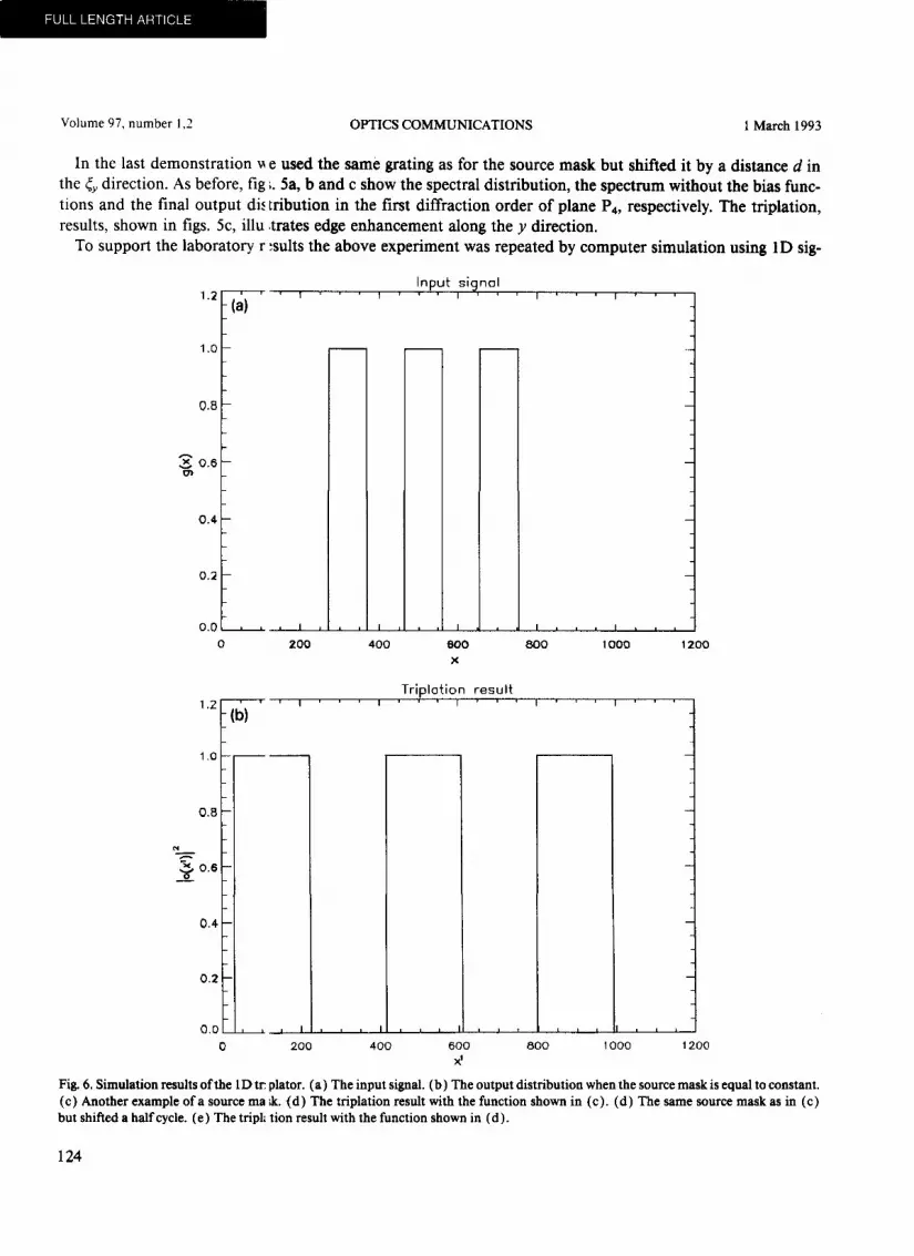
In the last demons t ra t ion ~ e used the same grating as for the source mask but shifted it by a distance d in the ~y direction. As before, fig ;. 5a, b and c show the spectral dis tr ibut ion, the spectrum without the bias func- tions and the final output dL, t r ibution in the first diffract ion order o f plane P4, respectively. The tr iplat ion, results, shown in figs. 5c, illu ;trates edge enhancement along the y direction.
To support the laboratory r .'suits the above exper iment was repeated by computer s imulat ion using 1D sig-
Input si ha l
(a)'
1.o
0.8
0.6
0.4 ¸
0.2
0.0 , , , i ,
0 200 400 000 800 1000 1200 x
FULL LENGTH ARTICLE
1 ,0 , - - r - -
1.Z.(b)
0 . 8 -
~ . ~ 0 . 6 -
0.4 -
0.2 -
T r i p l o t i o n r e s u l t
0.0 , , , i _=_._~__~._ ~ ~ ~ ~
0 200 400 600 800 1000 200
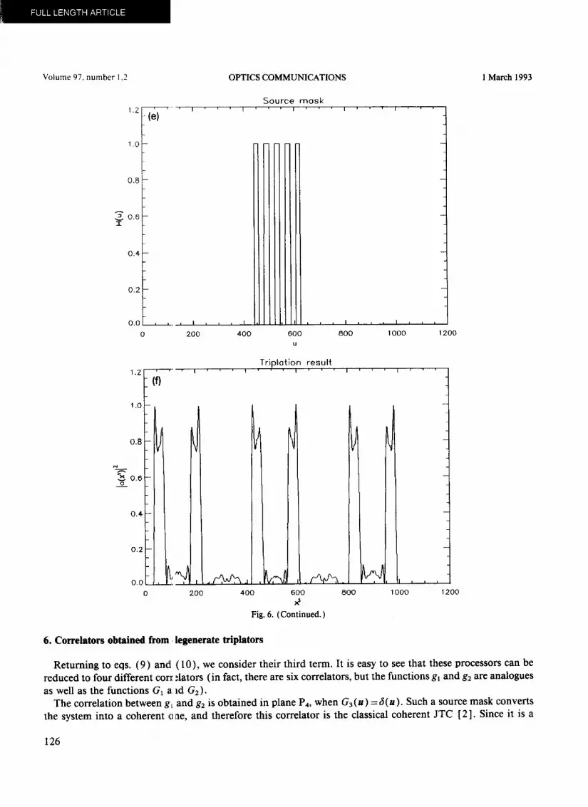
Fig. 6. Simulation results of the 1D tr. plator. (a) The input signal. (b) The output distribution when the source mask is equal to constant. (c) Another example of a source ma ;k. (d) The triplation result with the function shown in (c). (d) The same source mask as in (c) but shifted a half cycle. (e) The tripl~ tion result with the function shown in (d).
124

Volume 97, number 1,2 OPTICS COMMUNICATIONS 1 March 1993
nals. The input signal g(x) , and the triplation result, when H(u) = ~{h (x)} = G3 (u) = const, are shown in figs. 6a and b, respectively. The second tested function H(u), and the output result, with the same input (fig. 6a), are depicted in figs. 6c and d, respectively. Finally, the same grating of fig. 6c is shifted by a half cycle, as shown in fig. 6e. The consequential output result appears in fig. 6f. All these triplation results indicate similar behavior to the optical experimental results.
0.8
o.e "1-
0 .¢
0.2
O.Oi , I I
1 . 0 -
0,8 -
x 0 . ~ - _~o
Source mask I I I
I I
200 400 600 800 1000 1200 g
Tripl~tion resul t I I
~.z (c)
1.0
0 .0 . , ~ I , , t ~ - - . i , I
0 200 400 600 800" 1000 1200
x'
Fi& 6. (Continued.)
125
FULL L E N G T H ART ICLE
Volume 97, number 1,2 1 March 1993
1.Z
1.0
0.8
_ ,0 .6
0 .4
0.2
( e ) ' '
0.0 ,,.,I
0 200
OPTICS COMMUNICATIONS
S o u r c e m o s k i i i
a I
400
I J t i I i i i
~00 800 1000 1200
e,a
o . 6 - _ . .£_o
0.8 ~
I 0 ,4 - -
i
I! 0,0 , [ 0 200
i i
i , d , / ¢ ~ J ~ J
400
T r i p l a t i o n r e s u l t i i
600 800 1000 1200 x 1
Fig. 6. (Continued.)
6. Correlators obtained from, legenerate triplators
Returning to eqs. (9) and (10) , we consider their third term. It is easy to see that these processors can be reduced to four different corr ~lators (in fact, there are six correlators, but the functions g~ and g2 are analogues as well as the functions G1 a. ld G2).
The correlation between gt and g2 is obtained in plane P4, when G 3 (u) ---J(u ). Such a source mask converts the system into a coherent o ae, and therefore this correlator is the classical coherent JTC [ 2 ]. Since it is a
126

~LJ[~ i L f l 3 i ~ i z ~ / l i . , t L
Volume 97, number 1,2 OPTICS COMMUNICATIONS 1 March 1993
coherently illuminated system the rotation angle between the interferometer channels has no longer a physical meaning. The output distribution over plane P4 becomes
C(~) = ~ gl(~''g'(~'--~) d2~+ ~g2(r)g~(r--~, d2r+ f gl(~P)g2(, - ~ , d 2~+ ~g2(r,g,(r-~)d2r, (15, R R R R
with the last two terms representing the proper correlation distribution. There is no obvious advantage in im- plementing a JTC using interferometric architectures. Nevertheless, some attributes of such a system are now under study, in particular for the realization of complex reference functions by using only positive valued masks.
The other three correlators operate under spatially incoherent illumination and in all of them it is possible to implement a general complex impulse response function. The correlation in plane P3 is obtained between G2 and G3 if G~ is constant. In this case the intensity distribution in plane P3 is
I ( u ) = c o n s t . + / G 3 ( - u ' ) [G2(u-u')12dZu'+ ~ G~(u-u')G3(-u')d2u'+ ~ G2(u')G3(u'-u)d2u ' . (16)
In this particular case the correlation is obtained for any rotation angle since the function g~ is just a delta function at the origin, which remains unchanged by rotation. If G3(u) is considered as an input function, and g2(r) is taken as a spatial filter (therefore Gz(u) is an impulse response function), then the third (or the fourth) term of eq. (16) yields a correlation function between an intensity distribution input to a complex impulse response function. Compared to the multi pupil masks methods [ 9 ] of incoherent spatial filtering, this pro- posed configuration requires only one pupil mask, and is equivalent in the complexity to one of Leith's cor- relators (case 2 in ref. [ 10] ). However, unlike in the latter approach, here the correlation is done on an ir- radiance input transmittance, which means that the system can processes diffuse objects as well. A drawback of both these correlators is that there appears to be no way to separate the undesired terms of eq. (16) from the third term.
The two other correlators exist only if the rotation angle is larger then zero. The correlation between GI and G2 is obtained when G3 is constant which is obtained by a completely incoherent light source in plane P~. In this case the intensity distribution in plane P3 is given by
I (u) =const .+ f Gx(u' )G~(Eu-u') dEll'+ f G2(u' )GT(Eu-u') dEu ' . (17)
The usefulness of such correlator is not clear since it makes a correlation between the Fourier transforms of both input functions instead between the functions themselves.
The fourth correlator is obtained in plane P4, with g~ = const., and is given by
c(,,=ga(,)const.+g3(-,) ~ g2(r)g'~(r-~)d2r+ ~ g~(r)g3(2r+~)d2r+ f g2(r)g3(-2r+~)d2r. (18) R R R
The two last correlation terms can be easily separated in plane P4 by shifting g2 out of the origin. Considering g2(r) as the input function and G3(u) as a spatial filter, a correlation is obtained between two complex func- tions, although illuminated incoherently. To obtain a similar result with the method described in ref. [ 9 ], 6 different pupil masks are required. However, the drawbacks of this correlator mainly come from the low dif- fraction efficiency of the spectrum grating I(u) in plane P3-
7. Conclusion
A new integral transform, the triplator, was introduced and implemented optically. Mathematically, distin-
127
FULL LENGTH ARTICLE
Volume 97, number 1,2 OPTICS COMMUNICATIONS l March 1993
guishable feature of the triplal ion is that the transform to the Fourier domain yields a triplation too (eq. (8) ). Implementations of this oper~ tion in the field of image processing are currently under intensive investigation.
In principle, a sequence of: uch transforms can be used to generate the whole domain of a triple correlation. As far as we know, optical iml dementation of the triple correlation between 2D functions has never been done yet. The applications of the t iple correlation in the signal processing field are well summarized in ref. [6], and we would only like to me1 tion that the triple correlation is a generalization of an extended family of trans- forms and representations, lil :e ambiguity function, Wigner distribution, etc. That means that the proposed system may be used as an an~,log computer for many mathematical operations.
The triplator itself can be u ;ed for signal processing, similar to the conventional correlator, but with unique properties, such as sharp ideT tification peaks in pattern recognition schemes. Degeneration of the triplation yields a collection of correlatc rs, out of which three may be useful for incoherently illuminated correlation be- tween complex functions.
In the experimental work ~ e demonstrated the feasibility of implementation using some simple examples. Of course, the results for thes ~ simple cases could be also derived by conventional spatial filtering. However, the two procedures are subst~ ntially different and the triplation operation has additional possibilities. Some of these were indicated here ~ Jhile others are still under investigation.
Acknowledgements
This work was done Associateship.
while J. Rosen held a National Research Council-Rome Laboratory Research
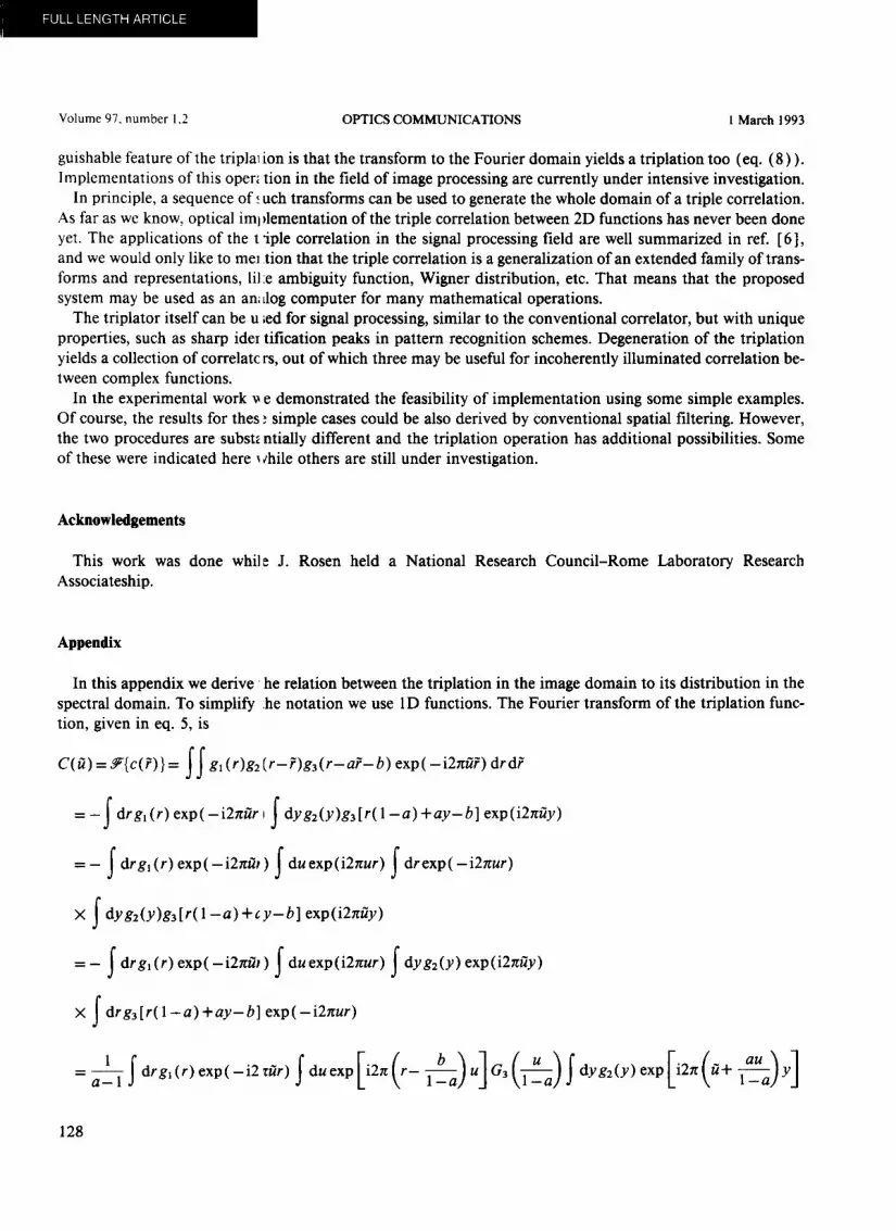
Appendix
In this appendix we derive h e relation between the triplation in the image domain to its distribution in the spectral domain. To simplify :he notation we use 1D functions. The Fourier transform of the triplation func- tion, given in eq. 5, is
C(~) = ~'{c(~)} = f f gx(r)g2(r-~)g3(r-a?-b) exp( - i2~ t~) drd?
= -~ drgl(r) exp(-i21t~r I ~ dyg2(y)ga[r(1-a)+ay-b] exp (i21t~y)
X ~ dyg2(y)ga[r(1 - a ) + c y - b ] exp(i21t~y)
=- ~ drgl(r)exp(-iE~tfi,) ~ duexp(iETtur) ~ dyg2(y)exp(iETt~y)
X ~ drga[r(1-a)+ay-b] exp(-i21tur)
b u exp Ii21t ( ~ + l__~a) y ] - a-ll ~drg~ (r)exp(-i2 zt~r) fdu exp D2zt ( r - ~ a - a ) u ] Ga (1--~a) ~dyg2(y) au
128

Volume 97, number 1,2 OPTICS COMMUNICATIONS 1 March 1993
la_l ~drg~(r)exp(-i2~tf~r)Sduexp[i2~t(r-l-~a)UlG3(1-~a)G2(-~-a+fZ)
_ la_l fduexp(-i2rtl-~U)Ga(l-~a)G2(-~-a+ft)fdrgt(r)exp[-i2~t(~-u)r]
- a - l l f duexp ( - i 2 ~ t ~ a - u)Ga(]--~_u a)G2(la_-~u a + ~ / ) G ~ ( ~ - u )
1 fduexp(_i2~ta_~(u_fQ)G,(u)G2(aUa fl ) ( u fl ) - l - a 1 a - l Ga a~_l a-I
1 fduexp(-i27ta-~(u-ff))G,(u)G3(u-fQG2(u-f4/a), 1-a m
where
a o3.
(19)
References
[ 1 ] J. Rosen, M. Segev, J. Shamir and A. Yariv, J. Opt. SOC. Am. A 9 (1992) 1498. [2] C.S. Weaver and J.W. Goodman, Appl. Optics 5 (1966) 1248. [3] S. Wang and N. George, Appl. Optics 24 (1985) 842. [ 4 ] M. Segev and A. Yariv, Optics Lett. 17 (1992) 145. [ 5] M. Born and E. Wolf, Principles of optics (Pergamon, New York, 1980). [6] A.W. Lohmann and B. Wirnitzer, Proc. IEEE 72 (1984) 889. [ 7 ] B.V.K. Vijaya Kumar, Appl. Optics 31 (1992) 4773; and many references therein. [ 8 ] C.F. Hester and D. Casasent, AppL Optics 19 (1980) 1758. [9] I. Glaser, Pro& in Optics, ed. E. Wolf, 24 (1987) 389.
[ 10] E.N. Leith and D.IC Angell, Appl. Optics 25 (1986) 499.
129


