Embed Size (px)
Citation preview

1
Tuning of Phase Locked Loops for PowerConverters under Distorted Utility Conditions
Francisco D. Freijedo, Member, IEEE , Jesus Doval-Gandoy, Member, IEEE, Oscar Lopez, Member, IEEE, andEnrique Acha, Senior Member, IEEE
Abstract—This paper presents a novel approach in the tuningof phase locked loops (PLLs) for power electronic converters.PLLs are implemented inside a higher level controller to estimatethe grid voltage phase-angle and then control the energy transferbetween the power converter and the ac mains. The tuning ofthe PLL is not a trivial task, specially when considering powerquality phenomena.
In a general way, PLLs with a low bandwidth (low-gain PLLs)are required when handling with distorted voltages. It is analyt-ically demonstrated in this paper that low-gain PLLs have moretrade-offs than high-gain PLLs (e.g. PLLs for communications):it is not possible to optimized the settling time for a phase-jump without getting slower the PLL response to frequencyvariations. Existing tuning methods do not take into accountlow-gain features, which may result in non-optimum designs.
The proposing PLL tuning methodology is based on inspectionof frequency-domain diagrams and, contrary to the other existingtuning methods, takes into account ’low-gain’ dynamics. It isassured an optimized performance in the presence of any kindof disturbances in the grid.
From practical point of view, the proposed tuning procedureis very intuitive for controller designers. Some significant designexamples and experimental results, obtained from a discreteimplementation (dSpace platform), are provided in order tovalidate the theoretical approaches.
Index Terms—ac/dc Power Conversion, Phase locked loops,Power Electronics Converters.
I. INTRODUCTION
Synchronization is one of the most important issues inthe control of power converters connected to the grid: thephase-angle of the fundamental vector of the ac mains voltageshould be measured in real time in order to set the energytransfer between the grid and the power converter. Most ofthe recently proposed control algorithms track the phase-angleand frequency of the utility voltage through phase lockedloops (PLLs); some significant applications are active powerfilters [1], [2], uninterruptible power supplies [3], power factorcontrol [4], [5], distributed power generation [6] and Flexibleac transmission systems [7], [8].
The basic scheme of three-phase PLL is the SynchronousReference Frame (SRF) PLL (SRF-PLL). Its inputs are the
Paper D3.12, presented at the 2009 IEEE Applied Power ElectronicsConference, Washington DC, USA.
Francisco D. Freijedo, Jesus Doval-Gandoy and Oscar Lopez arewith the Department of Electronic Technology, University of Vigo.Emails:{fdfrei,jdoval,olopez}@uvigo.es.
Enrique Acha is with the Department of Electronics & Electrical Engineer-ing, University of Glasgow. Email:[email protected].
This work was supported by the Spanish Ministry of Education and Scienceunder project number ENE2006-02930.
system set of voltages and it tracks the phase-angle of thefundamental positive-sequence. Its digital implementation wasfirstly analyzed in detail in [9]; under non distorted conditions,the SRF-PLL can be considered a very high performance al-gorithm because it is able to work with a very high bandwidth,providing a very fast and clean phase-angle estimation. How-ever, when distorted conditions are considered this bandwidthshould be drastically reduced in order to cancel ripple [9],[10].
Single-phase PLLs have also been proposed for the controlof power electronic converters [11]–[13]. A single-phase PLLtracks the phase angle of the fundamental component of itsinput signal. In general, it could be said that single-phase PLLsfor grid applications are more complex than the SRF-PLL;indeed it is a common practice to adapt the SRF-PLL structureto single-phase applications by means of orthogonal wavesgeneration [13].
The main difference between SRF-PLL and single-phasePLLs is that the SRF-PLL tracks the positive-sequence phase-angle not individual phase-angles. Therefore, SRF-PLLs seemto be more suitable to work with SRF controllers, such asdq and Proportional Integrator (PI) based current regulators,and single-phase PLLs to single-phase system and three-phasesystem with per-phase control.
Distortion in the ac mains should be taken into accountwhen tuning a PLL: there is a trade-off between filtering andtransient response. With the suitability of an ever increasingpotential of discrete devices, several techniques to improvethis trade-off have been proposed, such as the placementof extra filter inside the loop [14]–[17] or before the phasedetector (pre-filters) [7], [18], [19], and the implementationof complex feedback structures [14], [20], [21]. However, itcan be checked that the implementation of filtering techniquesalways leads to a drastic reduction in the whole bandwidthand therefore in the transient response speed. More specifi-cally, when optimization techniques affect to the closed-loopdynamics (filters inside and/or feedback), the PLL should betuned with a low bandwidth accordingly, giving rise to a low-gain PLL.
This paper analyzes in depth the dynamics of low-gainPLLs through the frequency response of their equivalentlinearized model. It is analytically proved that low-gain PLLsdo not respond equally to phase or frequency changes. Morespecifically, it is not possible to control the overshoot in thestep response (phase-jump) without affecting very much thedynamics when a frequency variation occurs. This fact is nottaken into account in previous works, which could easily result

2
PhaseDetector
cv
iv LoopFilter
VoltageControlledOscillator
ev
ov
( )cvcoo Kv+=ωω
(a) Block diagram of an analog PLL.
[Tdq]
oot θω +
++
VCO
∫−
π
π
vcoω
oω
.).( upvadv
qv
PD
LoopFilter
.).( upvb
.).( upvcoω∆
(b) A SRF-PLL.
++
VCO
∫−
π
π
oot θω + oω
vcoωLoopFilter
eθ
++
PD
eθ
oot θω +
+-
PDiit θω + oω∆
(c) Linear model of PLLs.
.).( upvi
cos(u)
++X PD VCO
∫−
π
π
oot θω +
vcoωLoopFilter
++
PDeθ
oot θω +
oωsin(u)
oω∆
(d) A multiplier-based single-phase PLL.
Figure 1. Block diagrams of PLLs.
in a non-optimal tuning.Taking into account ’low-gain’ features, a tuning method
for grid-connected PLLs is provided. This method is based oninspection of Bode and pole/zero diagrams, so it could be saidthat it is very intuitive and useful for the controller designer.Some significant design examples of SRF-PLL tuning areprovided and tested in real time. These test contemplateboth steady-state distortion and grid transients (faults). ThedSpace DS1103 platform, using the discrete solver, and aprogrammable ac source have been employed for the tests.Experimental results prove all the theoretical approaches.
II. BACKGROUND ON PLLS
A. Analog PLLs
An analog PLL is a non-linear circuit which synchronizesits output signal (vo) with a reference or input signal (vi) in
frequency (ωi = ωo) as well as in phase (θi = θo). The basicPLL scheme is composed by the three basic functional blocksshown in Fig. 1(a): the phase detector (PD), the loop filterand the voltage controlled oscillator (VCO). It is a feedbackstructure: the PD is a circuit that generates a voltage signalwhich represents the difference in phase between the inputsignal and the feedback signal. The PD output is filteredthrough the loop filter and this signal controls the VCO. TheVCO generates a signal of frequency ωo, from its nominalfrequency (ωvco) and the ”correction” voltage (vc). As said,the PD output represents the phase error, so it is expected itsaverage value (dc) to be zero in steady-state phase error, evenafter a phase step or a frequency step in the input [22].
B. SRF-PLL
Fig. 1(b) shows the block diagram of a SRF-PLL whichis implemented digitally. The digital VCO is an integratortogether a feedforward constant (ωvco = 2π50 rad/s). ThePark transformation (eq. (2) ) acts as phase detector and thequadrature component (vq) as phase-angle error signal (θe), sothat vq ≈ θe.
(vdvq
)︸ ︷︷ ︸
Vdq
= Tdq ·
vavbvc
︸ ︷︷ ︸
Vabc
(1)
where
T′
dq =23
sin(ωot +θo) cos(ωot +θo)sin(ωot +θo− 2π
3 ) cos(ωot +θo− 2π
3 )sin(ωot +θo + 2π
3 ) cos(ωot +θo + 2π
3 )
. (2)
It should be noticed that the Park transform can be obtainedfrom the Clarke transform (αβ frame) and an angle trans-form [9], [10]. Some single-phase PLLs generate a ’virtual’αβ frame to adapt the single-phase signal to the SRF-PLLstructure [13].
It is expected that, in steady-state, vq to be zero 1, andalso vd the amplitude of the fundamental component positive-sequence vector. Under such a situation, θe is zero and there-fore the system is tracking the positive-sequence fundamentalcomponent.
If only positive-sequence is considered in the input, theSRF-PLL is able to work with a very high Bandwidth (high-gain PLLs), which is one of the most attractive feature of thisalgorithm. However, when distorted conditions are considered,specially unbalance in the inputs, a low-gain tuning is recom-mended [9], [10].
1) Linearization: The SRF-PLL is a non-linear systemwhich should be linearized in order to study its dynamics [9],[10]. For the linearization, the system could be consideredaround the tracking point, that is ωi = ωo and θi ≈ θo, andalso balanced inputs. Under such a situation:
1vq ≡ average value of vq.

3
(vdvq
)︸ ︷︷ ︸
Vdq
=(
V cos(θi−θo)≈VV sin(θi−θo)≈V · (θi−θo) = V ·θe
)(3)
where V is the line to neutral peak voltage which shouldbe rearranged so that V = 1 p.u.. Fig. 1(c) shows the resultinglinear PLL employed to tune the SRF-PLL.
C. Single-phase PLLs
Fig. 1(d) shows the block diagram of a single-phase PLLusing a multiplier as phase detector [22]. It has been proposedto work with power electronic converters in [23] and enhancedimplementations has been proposed in [14], [17], [20]. Theinput signal of equation (4) is considered:
vi = V · sin(ωit +θi)+ f (3ωi,5ωi,7ωi, ...) p.u. (4)
The wave at the PD output is:
vi× cos(ωot +θo)︸ ︷︷ ︸Feedback wave
=V2
sin(ωit +θi−ωot−θo)+
+V2
sin(ωit +θi +ωot +θo)+ f (2ωi,4ωi,6ωi, ...)
(5)
This PLL can be also linearized, assuming that the PLLis locked in steady-state; under such a situation ωi = ωo andθi ≈ θ1, so:
vi× cos(ωot +θo)≈V2
sin(θi−θo)︸ ︷︷ ︸≈θi−θo=θe
+
+V2
sin(2ωit +2θi)︸ ︷︷ ︸Generated second harmonic
+ f (2ωi,4ωi,6ωi, ...)︸ ︷︷ ︸Other harmonics
(6)
Equation (6) shows that in steady-state the wave has a smalldc signal with the phase error information (θe), a high secondharmonic and other even harmonic components. The internallygenerated second harmonic should be canceled in order toavoid an unacceptable level of jittering 2; to achieve it, thebandwidth must be reduced in a drastic manner. So, on thecontrary to the SRF-PLL, the single-phase multiplier basedPLL is always a low-gain PLL (in grid applications).
Assuming that all the harmonic components are canceledin the LF, the linearized model of Fig. 1(c) is also valid forsingle-phase PLLs [22].
D. Other digital PLLs
As said, other three-phase and single-phase PLLs have beenproposed in the literature. For most of the cases it is immediateto check that they can be linearized in a similar manner that theSRF-PLL or the single-phase multiplier based PLL. If not, thestudy of dynamics cannot be done by means of linear analysiswhich makes more difficult the tuning.
+-
s1
oωPD
eθ
VCOiit θω +
oot θω +
)(sL
)(sH
Figure 2. Studied linear model.
III. FREQUENCY DOMAIN BASED TUNING
Fig. 2 shows the PLL linear model, which is suitable forstudying its dynamics. The linear model open loop transferfunction in the Laplace domain is given by the equation:
H(s) = L(s)︸︷︷︸Loop Filter
· 1s︸︷︷︸
VCO
. (7)
A. Stability Margins and Cut-off Frequency
The stability condition of the linear model throughthe open loop frequency response is: |H(s)| < 1 when∠H(s)≥−180deg. Two quantities are directly related withthis stability criterion: the phase margin (PM) and the gainmargin (GM). The crossover frequency (ωc) is referred tothe frequency at which |H(s)| is 1 (0 dB). In this point thePM is measured. PM is very useful to specify control systemperformance because it is related with the damping ratio ofthe system (ζ) [24]:
ζ∼=PM100
f or PM < 70deg . (8)
The information of PLL settling time (ts) can be obtainedfrom the H(s) frequency response, since ωc is approximatelyequal to the closed loop bandwidth (ω3dB) and natural (ωn)frequencies: ts to within 2% of the final value of a secondorder closed loop system can be estimated with
ts =4
ζωn≈ 4
ζωc(9)
[25]. Therefore, by inspection of the Bode diagram of H(s)the PLL transient response can be estimated accurately. From(9) a high ωc results in a fast system. However, a high ωcleads to a bad steady-state filtering: the choice of ωc is themain trade-off in the tuning [9], [10]. ts can also be optimizedincreasing ζ [7].
Stability margins and ωc can be estimated by differentfrequency domain methods such as Nyquist, Nichols and Bodediagrams. The use of Bode diagrams is employed in this work,since they provide information of both transient and steady-state performance.
2The term jittering, as defined in [22], comprises any kind of noise inmeasurements, e.g. harmonics ripple.

4
B. Steady-state Distortion and Bandwidth
The needed information for phase-angle tracking is thedc component after the phase detector. Any other harmoniccontent in the error signal causes jittering in the estimationand should be canceled [22]. For the single-phase PLL itis clear that the second harmonic is an annoying problemeven though the input signal is totally clean. The problemof the second harmonic appears in the SRF-PLL when thereis fundamental negative-sequence in the set of input voltages[10]. The presence of higher harmonics in the inputs couldalso result in a loss of performance [9], [10].
The very first action to cancel the presence of non dccomponents in the error signal was the reduction of the PLLbandwidth (ωc), so the closed loop has low gain at nondesired frequencies [9], [10]. The suitability of ever-increasingperformance digital devices allows the implementation ofmore complex discrete filters and techniques. Some significantproposals are
• the implementation of different kind of filters inside theloop filter to cancel for specific harmonics and unbalanceeffect [14]–[17].
• the use of filters before the phase detector (pre-filters) tocancel for specific harmonics and unbalance effect [7],[18], [19]. It should be noticed that the use of pre-filtersdoes not affect to PLL tuning, but reduces the wholebandwidth, since they cause a lag when there is an inputtransient.
• the implementation of complex feedback structures tocancel for second harmonic (single-phase PLLs) andunbalance effect (SRF-PLL) [14], [20], [21].
Fig. 3 explains by itself the pros and cons of introducing ex-tra filters inside the loop (L(s)). Indeed, the magnitude versusfrequency response allows to cancel for specific components.However, each filter introduces phase inside the loop, whichresults in a reduction of stability margins. Therefore, in orderto have an acceptable PM, when extra filters are placed insidethe loop, the bandwidth (ωc) should be reduced. It could besaid that, in general, the better the filter cancellation patternof a specific filter, the worse its phase response. Moreover, itshould be also noticed that the effect of adding extra feedbacksignals results in a drastic bandwidth reduction [21].
00.2
0.4
0.6
0.8
1
Mag
nitu
de (a
bs)
50 100 150 200 250 300 350 400-180
-90
0
90
Phas
e (d
eg)
Frequency (Hz)
Notch (Q=10)Notch (Q=1)Moving Average
Figure 3. Frequency response of different filters for canceling harmonics.
C. Grid Events and Transient Responses
Typical power system electromagnetic phenomena relatedwith transients in the input of the PLL are voltage variation(sag and swells), phase-angle shifts or phase jumps andfrequency deviations [26].
The bandwidth is set by the gain of the loop filter, but also,by the amplitude of the input signal as shown in section II-B1.This is indeed a limitation of PLLs: the dynamics dependson the input amplitude. A practical problem appears when avoltage sag is in the inputs. Usually, voltage sags have a phase-jump associated [27]. Under such a situation, a low-gain PLLis even slower than usual, and therefore the re-tracking timecould be unacceptable. To overcome this situation the PD inputcan be normalized using an amplitude estimation, but it addscomplexity to the PLL as well as to the dynamics assessment[7], [14], [19], [20].
Another limitation of low-gain PLLs, which is analyticallyproved below, is the fact that the settling times in the presenceof phase-jumps or frequency deviations could be very differ-ent. More specifically, the step response of Fig. 2 model isnot accurate for frequency steps when H(s) overdamped. Thisintroduces a new trade-off in the design of the PLL, since, itis not possible to optimize ts for phase jumps without gettingworse the response to frequency deviations.
The error transfer function relating the phase error θe to theinput phase θ1 is:
He(s) =1
H(s)+1. (10)
The Laplace transform of the phase error when a phase stepor phase jump (∆θ) is applied at time t = 0 is [22]:
Θ∆θe (s) = He(s) ·
∆θ
s. (11)
Through the final value theorem, a PLL has zero averagesteady state phase error after a phase jump if:
θ∆θe (∞) = lim
s→∞s ·Θ∆θ
e (s) = 0. (12)
In the same way, the Laplace transform of the phase errorwhen a frequency step (∆ω) is applied at time t = 0 is:
Θ∆ωe (s) = He(s) ·
∆ω
s2 . (13)
and
θ∆ωe (∞) = lim
s→∞s ·Θ∆ω
e (s) = 0 (14)
assures zero steady-state phase error after a frequency step.The condition imposed by (14) requires of two origin poles
in H(s) giving rise to a type 2 PLL [28]. Applied to the PLLsof Fig. 1 if there is no origin poles in L(s) this PLL doesnot have zero average steady-state phase error when the inputsignal is not rotating at the frequency set by the feedforwardconstant of the VCO (ωvco). Typical digital PLLs implementsPIs as loop filter resulting in type 2 PLL [10]. The use ofa lag-lead filter (lag compensator) instead of a PI filter, asproposed e.g. in [29], results in type 1 PLL which does notassure tracking under frequency deviations.

5
Eqs. (12) and (14) does not provide information abouthow long the transients last. In order to study the transientresponses of the PLL, the inverse Laplace transform is appliedto eqs. (12) and (14). This analysis is performed assuming thatL(s) is a PI filter (type 2 PLL):
L(s) = Kp +Ki
s, (15)
where Kp and Ki are the proportional and integral constants,respectively. This approach is valid even though extra discretefilters are present inside the loop, since, from stability condi-tions, their implementation require a ’low gain’ and therefore,the dominant roots are the PI filter ones.
Eqs. (11) and (13), expressed also as function of ζ and ωn,are:
Θ∆θe (s) =
∆θss2 +Kps+Ki
=∆θs
s2 +2ζωns+ω2n, (16)
and
Θ∆ωe (s) =
∆ω
s2 +Kps+Ki=
∆ω
s2 +2ζωns+ω2n. (17)
The expression of θ∆θe (t) and θ∆ω
e (t) in the time domain(being t = 0 the moment of the transient) depends on the rootsof the denominator (p1 and p2):
p1,2 =−Kp±
√K2
p−4Ki
2=−ωn(ζ±
√ζ2−1). (18)
a) Underdamped Case: ζ < 1:
θ∆θe (t) =
∆θ√1−ζ2
· e−ζωnt · sin(ωn
√1−ζ2t +φ) (19)
where φ = tan−1(√
1−ζ/−ζ), and
θ∆ωe (t) =
∆ω
ωn√
1−ζ2· e−ζωnt · sin(ωn
√1−ζ2t). (20)
b) Overdamped Case: ζ > 1:
θ∆θe (t) =
∆θ
2√
ζ2−1[(1−
√ζ2−1) · e−ζωn(1−
√ζ2−1)t︸ ︷︷ ︸
slow pole
−
−(1+√
ζ2−1) · e−ζωn(1+√
ζ2−1)t︸ ︷︷ ︸f ast pole
] =
∆θ
2√
ζ2−1[(1−
√ζ2−1) · ep2t︸ ︷︷ ︸
slow pole
−(1+√
ζ2−1) · ep1t︸ ︷︷ ︸f ast pole
]
(21)
and
θ∆ωe (t) =
∆ω
2ωn√
ζ2−1[e−ζωn(1−
√ζ2−1)t︸ ︷︷ ︸
slow pole
−
−e−ζωn(1+√
ζ2−1)t︸ ︷︷ ︸f ast pole
] =∆ω
2ωn√
ζ2−1[ ep2t︸︷︷︸slow pole
− ep1t︸︷︷︸f ast pole
](22)
From eqs. (19) and (20), it is clear that for the underdampedcase the transient response can be improved both increasingKi (ωn) or Kp (ζ). However, for overdamped situation thesituation is not clear at all. Eqs. (21) and (22) have two terms,one decaying with ep1t (fast pole) and another with ep2t (slowpole).
In the case of θ∆θe (t) (phase-jump) the term associated with
the slow pole has associated a smaller coefficient. If the systemis tuned so |p1|>> |p2| the transient response only dependson the fast pole, so this transient response can be improvedincreasing ζ. A step response with almost no overshoot canbe achieved. It should be noticed that an increase in ζ isalso equivalent to an increasing in the PM. The problemof this approach arises when θ∆ω
e (t) (frequency deviation) isconsidered (eq. (22)). The terms associated to the slow polehas the same magnitude than the other one. If p2 is very closeto the origin, the transient defined by θ∆ω
e (t) lasts very much.Fig. 4(a) shows a diagram of poles/zeros for underdamped
and overdamped situations. As larger is the distance of thedominant poles to the imaginary axis, the faster is the transientresponse. Moreover, the higher the imaginary part of a pole,the higher the overshoot. Therefore, for the case of Θ
∆θe (s), it
is clear that the transient response to a phase-jump is better forthe overdamped case because the dominant pole is p1, sincep2 is almost canceled by the origin pole (Fig. 4(b)). However,in the case of Θ∆ω
e (s) the absence of zero in the overdampedtuning leads to a situation where p2 is the dominant root, andtherefore, the underdamped case has a better frequency steptransient (Fig. 4(c)). Therefore, it seems that a tuning aroundcritical damping (K2
p ≈ 4Ki, so that ζ≈ 1) results in the bettertrade-off for transient responses, even though the overshoot inθ∆θ
e (t) is not canceled.
(a) Poles-zeros diagram for Θe(s)∆θ and Θe(s)∆ω . Blue poles refer to ζ < 1and green poles to ζ > 1. The origin zero (red) is only present in Θe(s)∆θ .
(b) θ∆θe (t) comparative. (c) θ∆ω
e (t) comparative.
Figure 4. Comparative between underdamped and overdamped cases.
Finally, it should be noticed that a similar approach can bemade in the Z-domain obtaining the equivalent results. A very

6
overdamped system in the Z-domain has its dominant polesvery close to the unity circle [7]. As PLLs are implemented ina discrete device, an analysis/tuning in the Z-domain seems tobe more suitable. However, the analysis/tuning could be madein the Laplace domain if the sampling frequency ( fs) is highenough when compared with the dominant poles frequency;the poles/zeros place in the Laplace domain is much moreintuitive to predict the time constants of the system.
D. Limitations of existing tuning approaches for low-gainPLLs
First of all, it should be noticed that the Evans root-locusdiagram does not provide an accurate tuning of ’low-gain’PLLs: a type II PLL has a zero close to the origin (dominantroot). Its effect is negligible when the dominant poles arehigh, but not when they are also close to the origin. Inpractice, Evans root locus does not provide a reliable overshootinformation from its ζ for low-gain type II PLLs. It should benoticed that, in control theory, the Evan root-locus is providedto analyze second order systems without zeros [24].
In [7], [9], [10] analytical methods to predict the bandwidthand overshoot of PI based type II PLLs are provided. It canbe easily checked that low overshoot tuning results in veryoverdamped systems which lead to big transient response inthe presence of frequency steps. Moreover, if extra filters(notch, MAF, DSC) are placed, those methods, by themselves,are not accurate (PM and ωc change).
When comparing with previous tuning methods, two impor-tant new outcomes can be extracted from this paper approach:• PM and ωc information from the Bode diagram provides
a very reliable information to tune a PLL when extraharmonics/noise filters are placed inside the loop (low-gain PLLs).
• The PI filter coefficients tuning should not give rise tovery overdamped system, which damages the transientresponse in the presence of frequency deviations, whichhad been previously reported as an optimum tuning [7].
IV. DESIGN EXAMPLES
Some significant examples are shown in order to provide acomparison among tuning strategies. The sampling frequency( fs) is 10 kHz and the nominal frequency 50 Hz.
A. High Bandwidth SRF-PLL (HB-PLL)
A SRF-PLL with a very high Bandwidth is designed:
L(s)HB−PLL = (Kp +Ki
s)︸ ︷︷ ︸
PI f ilter
(23)
Table ISIGNIFICANT PARAMETERS OF HB-PLL
ωc( rad/s) PM(deg) Kp Ki p1( rad/s) p2( rad/s)4.56 ·103 49 4000 107 (−2+ i2.45) ·103 p∗1
102 103 104 105-210
-150
-120-20
20
40
60
80
Figure 5. Frequency response of H(z) for the HB-PLL (L(s)HB−PLL wasdiscretized using the ’zoh’ method).
From Fig. 5 and table I, it is expected a PLL with a veryfast transient response both for phase jumps and frequencydeviations. Some overshoot is expected. There is not har-monic/unbalance cancellation.
B. Unbalance/Notch SRF-PLL (UN-PLL)
A SRF-PLL for canceling the second harmonic generatedby the negative sequence using a notch filter is designed:
L(s)UN−PLL = (Kp +Ki
s)︸ ︷︷ ︸
PI f ilter
·N(s) (24)
where N(s) is a notch filter at 100 Hz with Q = 1.25.
Table IISIGNIFICANT PARAMETERS OF UN-PLL
ωc( rad/s) PM(deg) Kp Ki p1( rad/s) p2( rad/s)145 (23 Hz) 70 141.44 5000 −71.9 −69.6
10-1 100 101 102 103 104-225
-180
-135
-90
-45
0-150
-100
-50
0
50
100
Figure 6. Frequency response of H(z) for the UN-PLL (L(s)UN−PLL wasdiscretized using the ’zoh’ method).
From Fig. 6 and table II it is expected a PLL with anacceptable transient response both for phase and frequencyjumps with some overshoot, since the system is near criticaldamping (p1 ≈ p2). It has very good unbalance cancellationand an acceptable harmonic filtering.

7
C. SRF-PLL with Moving Average Filter (MA-PLL)
A SRF-PLL is designed to have a very good har-monic/unbalance cancellation in steady-state. L(s) is:
L(s)MA−PLL = (Kp +Ki
s)︸ ︷︷ ︸
PI f ilter
·MA(s) (25)
where MA(s) is the transfer function of a moving averagefilter tuned to cancel even harmonics; it is better expressed inthe Z-domain ( fs = 10 kHz):
MA(z) =1
1001− z−100
1− z−1 (26)
Table IIISIGNIFICANT PARAMETERS OF MA-PLL
ωc( rad/s) PM(deg) Kp Ki p1( rad/s) p2( rad/s)69 (11 Hz) 69 70 70 −68.98 −1.02
100 101 102 103 104-315
-270
-225
-135
-90
-300
-200
-100
Figure 7. Frequency response of H(z) for the MA-PLL (PI filter wasdiscretized using the ’zoh’ method).
From Fig. 7 and table III it is expected a SRF-PLL withan excellent harmonic/unbalance cancellation, an acceptablephase-jump transient response (decaying with ep1t ) with noovershoot (high PM), but with a bad frequency variationtransient (decaying with ep2t ).
V. EXPERIMENTAL RESULTS
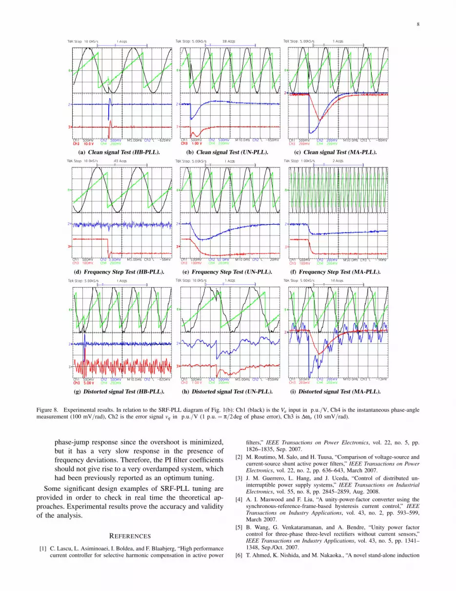
The SRF-PLLs of section IV have been implemented ina digital device (dSpace DS1103) using the discrete solver atfs = 10 kHz. The execution times of all SRF-PLLs were lowerthan 10 µs. The three-phase input voltages have been generatedwith a three-phase programmable ac source (three Chroma61501 modules). In order to obtain the test signals the three-phase ac source has been used as an arbitrary power amplifierconnected to a three-phase arbitrary waveform generator basedon a DSP card. The input signals have been acquired throughthe dSpace I/O interface by means of LEM LV25-P voltagetransducers and adapted to p.u. units. Fig. 8 shows theexperimental results key figures.
Figs. 8(a), 8(b) and 8(c) show experimental results whenthe SRF-PLLs were tested using a clean signal (no harmon-ics/noise) having a phase-jump of +45deg; the input frequency
was 49.5 Hz. Steady state and phase-jump transient responsesare shown. From these results it is clear that the HB-PLL isthe best option when there is not distortion, since it has a veryfast re-tracking and good steady-state phase-angle estimation.As expected from their bandwidth, the other two systems areslower.
In the frequency step tests (Figs. 8(d), 8(e) and 8(f)) suddenfrequency changes in the input waves (alternating between49 Hz and 51 Hz) were programmed in order to show the re-sponse of each system in the presence of frequency deviations.As expected, the frequency step and phase jump transienttimes are almost equivalent for not very overdamped systems(HB-PLL and UN-PLL). For MA-PLL (very overdamped)the optimization in the phase transient settling time (lowovershoot) resulted in a very slow response in the presenceof frequency deviations.
In the distorted signal test (Figs. 8(g), 8(h) and 8(i)), the pre-programed input waves have unbalance (≈ 10% of negativesequence ) and high ammount of harmonics (10% of 5th, 5%of 5th and 5% of 11th ); the input frequency was 50.5 Hz.Excellent results are obtained for MA-PLL in steady-statefiltering, thanks to the moving average filter, which cancelsall even harmonics. UN-PLL has a very good unbalancecancelation (second harmonic cancelation in ∆ωo) and anacceptable harmonic filtering. Due to its high bandwidth, HB-PLL does not filter either harmonics or unbalance.
From these results, it could be stated that a previousknowledge of the grid level distortion is very recommendedwhen tuning a PLL. It should be noticed that, very overdamped(e.g. MA-PLL) and very high bandwidth (e.g. HB-PLL) PLLspresent some important drawbacks when dealing with powerquality phenomena, which may lead to a poor energy exchangecontrol (between the grid and the power electronic converter).Therefore, an ’average’ system (no overdamped, mediumbandwidth), such as UN-PLL, could be a good choice for mostof the applications.
VI. CONCLUSIONS
This works presented an in depth study of the dynamics ofdigital PLLs for grid-connected power electronic converters.A review of the most employed PLL architectures and thelinearization technique is contributed in section II.
Section III reviews some PLL theory important concepts andproposes a tuning approach based on inspection of Bode andpole/zero diagrams. From a practical point of view it couldbe said that the proposed tuning method is very intuitive.Moreover, two new significant outcomes are contributed inthis paper:
1) PM and ωc information from the Bode diagram providesa very reliable information to tune a PLL when extraharmonics/noise filters are placed inside the loop (low-gain PLLs). This information is much more reliablethat the obtained from analytical methods having intoaccount only the PI filter roots.
2) It is analytically proved that low-gain PLLs have a trade-off between the responses to phase-jumps and frequencydeviations. A very overdamped PLL has an optimized
8
(a) Clean signal Test (HB-PLL). (b) Clean signal Test (UN-PLL). (c) Clean signal Test (MA-PLL).
(d) Frequency Step Test (HB-PLL). (e) Frequency Step Test (UN-PLL). (f) Frequency Step Test (MA-PLL).
(g) Distorted signal Test (HB-PLL). (h) Distorted signal Test (UN-PLL). (i) Distorted signal Test (MA-PLL).
Figure 8. Experimental results. In relation to the SRF-PLL diagram of Fig. 1(b): Ch1 (black) is the Va input in p.u./V, Ch4 is the instantaneous phase-anglemeasurement (100 mV/rad), Ch2 is the error signal vq in p.u./V (1 p.u. = π/2deg of phase error), Ch3 is ∆ωo (10 smV/rad).
phase-jump response since the overshoot is minimized,but it has a very slow response in the presence offrequency deviations. Therefore, the PI filter coefficientsshould not give rise to a very overdamped system, whichhad been previously reported as an optimum tuning.
Some significant design examples of SRF-PLL tuning areprovided in order to check in real time the theoretical ap-proaches. Experimental results prove the accuracy and validityof the analysis.
REFERENCES
[1] C. Lascu, L. Asiminoaei, I. Boldea, and F. Blaabjerg, “High performancecurrent controller for selective harmonic compensation in active power
filters,” IEEE Transactions on Power Electronics, vol. 22, no. 5, pp.1826–1835, Sep. 2007.
[2] M. Routimo, M. Salo, and H. Tuusa, “Comparison of voltage-source andcurrent-source shunt active power filters,” IEEE Transactions on PowerElectronics, vol. 22, no. 2, pp. 636–643, March 2007.
[3] J. M. Guerrero, L. Hang, and J. Uceda, “Control of distributed un-interruptible power supply systems,” IEEE Transactions on IndustrialElectronics, vol. 55, no. 8, pp. 2845–2859, Aug. 2008.
[4] A. I. Maswood and F. Liu, “A unity-power-factor converter using thesynchronous-reference-frame-based hysteresis current control,” IEEETransactions on Industry Applications, vol. 43, no. 2, pp. 593–599,March 2007.
[5] B. Wang, G. Venkataramanan, and A. Bendre, “Unity power factorcontrol for three-phase three-level rectifiers without current sensors,”IEEE Transactions on Industry Applications, vol. 43, no. 5, pp. 1341–1348, Sep./Oct. 2007.
[6] T. Ahmed, K. Nishida, and M. Nakaoka., “A novel stand-alone induction

9
generator system for AC and DC power applications,” IEEE Transac-tions on Industry Applications, vol. 43, no. 6, pp. 1465–1474, Nov./Dec.2007.
[7] H. Awad, J. Svensson, and M. J. Bollen, “Tuning software phase-lockedloop for series-connected converters,” IEEE Transactions on PowerDelivery, vol. 20, no. 1, pp. 300–308, Jan. 2005.
[8] H. Akagi, S. Inoue, and T. Yoshii, “Control and performance of atransformerless cascade PWM STATCOM with star configuration,” IEEETransactions on Industry Applications, vol. 43, no. 4, pp. 1041–1049,Jul./Aug. 2007.
[9] V. Kaura and V. Blasko, “Operation of a phase locked loop system underdistorted utilityconditions,” IEEE Transactions on Industry Applications,vol. 33, no. 1, pp. 58–63, Jan./Feb. 1997.
[10] S.-K. Chung, “A phase tracking system for three phase utility interfaceinverters,” IEEE Transactions on Power Electronics, vol. 15, no. 3, pp.431–438, May 2000.
[11] L. N. Arruda, S. M. Silva, and B. J. C. Filho, “PLL structures for utilityconnected systems,” in Industry Applications Conference, 2001. Thirty-Sixth IAS Annual Meeting. Conference Record of the 2001 IEEE, vol. 4,Chicago, IL, USA, Sep./Oct. 2001, pp. 2655–2660.
[12] M. Karimi-Ghartemani and M. R. Iravani, “A nonlinear adaptive filter foronline signal analysis in powersystems: applications,” IEEE Transactionson Power Delivery, vol. 17, no. 2, pp. 617–622, Apr. 2002.
[13] S. Shinnaka, “A robust single-phase PLL system with stable and fasttracking,” IEEE Transactions on Industry Applications, vol. 44, no. 2,pp. 624–633, Mar./ 2008.
[14] D. Jovcic, “Phase locked loop system for FACTS,” IEEE Transactionson Power Systems, vol. 18, no. 3, pp. 1116–1124, Aug. 2003.
[15] A. V. Timbus, R. Teodorescu, F. Blaabjerg, M. Liserre, and P. Rodriguez,“PLL algorithm for power generation systems robust to grid voltagefaults,” in Power Electronics Specialists Conference, 2006. PESC ’06.37th IEEE, Jeju, Jun. 2006, pp. 1–7.
[16] T. Ostrem, W. Sulkowski, L. Norum, and W. Yadong, “Phase-locked loopwith adaptive signal cancellation for three-phase network side voltagesource inverter,” in Power Electronics and Applications, 2007 EuropeanConference on, Aalborg,, Sep. 2007, pp. 1–10.
[17] F. D. Freijedo, J. Doval-Gandoy, O. Lopez, and C. Jacobo, “Robustphase locked loops optimized for dsp implementation in power qualityapplications,” in 34th Annual Conference on IEEE Industrial Electronics,IECON 2008, Orlando, USA, Nov. 2008.
[18] P. Rodriguez, R. Teodorescu, I. Candela, A. V. Timbus, M. Liserre,and F. Blaabjerg, “New positive-sequence voltage detector for gridsynchronization of power converters under faulty grid conditions,” inPower Electronics Specialists Conference, 2006. PESC ’06. 37th IEEE,Jun. 2006, pp. 1–7.
[19] F. Bradaschia, J. P. Arruda, H. Souza, G. M. S. Azevedo, F. A. S.Neves, and M. C. Cavalcanti, “A method for extracting the fundamentalfrequency positive-sequence voltage vector based on simple mathemati-cal transformations,” in Power Electronics Specialists Conference, 2008.PESC 2008. IEEE, Rhodes,, Jun. 2008, pp. 1115–1121.
[20] F. D. Freijedo, J. Doval-Gandoy, O. Lopez, D. Pineiro, C. M. Penalver,and A. A. Nogueiras, “Real-time implementation of a SPLL for FACTS,”in 32nd Annual Conference on IEEE Industrial Electronics, IECON2006, Paris, France, Nov. 2006, pp. 2390–2395.
[21] P. Rodriguez, J. Pou, J. Bergas, J. I. Candela, R. P. Burgos, andD. Boroyevich, “Decoupled double synchronous reference frame PLLfor power converters control,” IEEE Transactions on Power Electronics,vol. 22, no. 2, pp. 584–592, Mar. 2007.
[22] R. E. Best, Phase Locked Loops. Design, Simulation and Applications.4th Edition. McGraw-Hill, 1999.
[23] G. H. Jung, G. C. Cho, S. W. Hong, and G. H. Cho, “DSP based controlof high power static VAr compensator using novelvector product phaselocked loop,” in Power Electronics Specialists Conference, 1996. PESC’96 Record., 27th Annual IEEE, vol. 1, Baveno, Italy, Jun. 1996, pp.238–243.
[24] G. F. Franklin, J. D. Powell, and A. Emami-Naeini, Feedback Controlof Dynamic Systems. Pearson Education, 2002.
[25] R. C. Dorf and R. H. Bishop, Modern Control Systems, Ninth Edition,., Ed. Prentice Hall, 2000.
[26] “IEEE Standard 1159-1995. IEEE Recommeded Practice for MonitoringElectric Power Quality.”
[27] M. H. J. Bollen., Understanding power quality problems. Voltage sagsand interrupions., R. J. Herrick., Ed. IEEE Press Editorial Board.,2000.
[28] F. M. Gardner, PhaseLock Techniques. John Wiley and Sons, 2004.
[29] C. Zhan, V. K. Ramachandaramurthy, A. Arulampalam, C. Fitzer,S. Kromlidis, M. Bames, and N. Jenkins, “Dynamic voltage restorerbased on voltage-space-vector PWM control,” IEEE Transactions onIndustry Applications, vol. 37, no. 6, pp. 1855–1863, Nov./Dec. 2001.
Francisco D. Freijedo (M’07) was born in Spain, in1978. He received the M.Sc. degree in physics fromthe University of Santiago de Compostela, Santiagode Compostela, Spain, in 2002. Since 2003, he hasbeen working toward the Ph.D. degree with theDepartment of Electronic Technology, University ofVigo, Vigo, Spain.
He is currently Lecturer at the University ofVigo. His research interests include power qualityproblems, grid-connected switching converters, acpower conversion, and FACTS.
Jesus Doval-Gandoy (M’99) received the M.Sc. de-gree from Polytechnic University of Madrid,Madrid,Spain, in 1991, and the Ph.D. degree from theUniversity of Vigo, Vigo, Spain, in 1999.
From 1991 to 1994, he worked at industry. He iscurrently an Associate Professor with the Universityof Vigo. His research interest is in the area of acpower conversion.
Oscar Lopez (M’05) was born in Spain, in 1975. Hereceived the M.Sc. and the Ph.D. degrees from theUniversity of Vigo, Vigo, Spain, in 2001 and 2009,respectively.
He is currently an Assistant Professor with theUniversity of Vigo. His research interest is in theareas of power switching converters technology.
Enrique Acha (SM’02) was born in Mexico. Hegraduated from Universidad Michoacana de SanNicolas de Hidalgo, Morelia, Michoacan, Mexico in1979 and obtained his PhD degree from Universityof Canterbury, Christchurch, New Zealand in 1988.He was a postdoctoral Fellow at the University ofToronto, Toronto, ON, Canada, and the Universityof Durham, Durham, England. He has written threetext books on various aspects of power electronicapplications in electrical power systems and over onehundred research papers.
He is the Professor of Electrical Power Systems at the University ofGlasgow, Glasgow, Scotland. He is an IEEE PES Distinguished Lecturer.