Embed Size (px)
Citation preview
Interactions
Uni
t6
M363 Unit 6UNDERGRADUATE COMPUTING
Software engineeringwith objects
This publication forms part of an Open University course M363
Software engineering with objects. Details of this and other Open
University courses can be obtained from the Student Registration and
Enquiry Service, The Open University, PO Box 197, Milton Keynes
MK7 6BJ, United Kingdom: tel. +44 (0)845 300 60 90,
email [email protected]
Alternatively, you may visit the Open University website at
http://www.open.ac.uk where you can learn more about the wide range
of courses and packs offered at all levels by The Open University.
To purchase a selection of Open University course materials visit
http://www.ouw.co.uk, or contact Open University Worldwide, Michael
Young Building, Walton Hall, Milton Keynes MK7 6AA, United Kingdom
for a brochure. tel. +44 (0)1908 858793; fax +44 (0)1908 858787;
email [email protected]
Java and all Java-based trademarks are trademarks of Sun
Microsystems, Inc; Motif is a registered trademark of the Open Group;
Rational Unified Process is a registered trademark of International
Business Machines Corporation; Unified Modeling Language and UML
are trademarks of Object Management Group, Inc. Design by Contract
is a trademark of Interactive Software Engineering. Other product and
company names may appear in the M363 course material. Rather than
use a trademark symbol with every occurrence of a trademarked
name, we use the names only in an editorial fashion and to the benefit
of the trademark owner, with no intention of infringement of the
trademark.
The Open University
Walton Hall
Milton Keynes
MK7 6AA
First published 2008.
Copyright ª 2008 The Open University.
All rights reserved. No part of this publication may be reproduced,
stored in a retrieval system, transmitted or utilised in any form or by
any means, electronic, mechanical, photocopying, recording or
otherwise, without written permission from the publisher or a licence
from the Copyright Licensing Agency Ltd. Details of such licences (for
reprographic reproduction) may be obtained from the Copyright
Licensing Agency Ltd, Saffron House, 6–10 Kirby Street, London
EC1N 8TS; website http://www.cla.co.uk
Open University course materials may also be made available in
electronic formats for use by students of the University. All rights,
including copyright and related rights and database rights, in electronic
course materials and their contents are owned by or licensed to The
Open University, or otherwise used by The Open University as
permitted by applicable law.
In using electronic course materials and their contents you agree that
your use will be solely for the purposes of following an Open University
course of study or otherwise as licensed by The Open University or its
assigns.
Except as permitted above you undertake not to copy, store in any
medium (including electronic storage or use in a website), distribute,
transmit or retransmit, broadcast, modify or show in public such
electronic materials in whole or in part without the prior written consent
of The Open University or in accordance with the Copyright, Designs
and Patents Act 1988.
Edited and designed by The Open University.
Typeset by The Open University.
Printed in the United Kingdom by Thanet Press Ltd, Margate
ISBN 978 0 7492 1612 2
1.1

CONTENTS
1 Introduction 5
2 Design by Contract 6
2.1 The contract to produce quality software 6
2.2 How can Design by Contract help to improvequality? 8
2.3 Contracts in the real world 9
2.4 Contracting, subcontracting and inheritance 11
2.5 Summary of section 15
3 Starting dynamic modelling 16
3.1 Focusing on a solution 16
3.2 Starting to build a sequence diagram 18
3.3 Assigning responsibilities in design 21
3.4 Sequence-diagram notation 22
3.5 Designing with sequence diagrams 25
3.6 Summary of section 30
4 Working with interaction diagrams 31
4.1 Message results and parameterised interactions 34
4.2 Creation and deletion 36
4.3 Levels of detail 38
4.4 Summary of section 42
5 Design decisions 43
5.1 Managing associations 43
5.2 Link manipulation 44
5.3 Forks and cascades 47
5.4 Summary of section 52
6 Summary 53
References 55
Index 56

M363 COURSE TEAM
Robin Laney, Course Chair, Author and Academic Editor
Leonor Barroca, Author
Ralph Greenwell, Course Manager
Charles Haley, Author
Nigel Kermode, Critical Reader
Martin Shepperd, External Assessor, Brunel University
Richard Walker, Critical Reader
Andy Allum, Course Website Developer
Kim Dulson, Software Procurement
Phillip Howe, Media Assistant
Callum Lester, Software Developer
Tara Marshall, Print Procurement
Sandy Nicholson, Freelance Copy Editor
Andy Seddon, Media Project Manager
Lucinda Simpson, Editor
Sue Stavert, Technical Tester
Andrew Whitehead, Graphic Artist
Thanks are due to the Desktop Publishing Unit, Faculty of Mathematics and
Computing.
1 Introduction
The aim of this unit is to show you how to make the transition from a software
specification consisting of use cases and a class model, which has no operations, to a
detailed class model with operations, which is ready to be implemented.
1 Introduction 5
2 Design by Contract
Perhaps somewhere in your studies you have asked yourself the question, ‘What is it
about objects that works?’ There is a simple answer to this question: ‘Object orientation
works because it uses “real-world-shaped pieces” to build systems.’ Objects exist in
the real world – you see and interact with them every day, and use them to build other
things; in this way they are familiar to use. You gain the ability to work with objects very
early in your life – the notion of an object, and your ability to work with them, very
quickly becomes part of your intellectual equipment.
Object-oriented software development builds on this familiarity by providing a
traceable path from the conceptualisation of real-world objects during analysis and
their construction during design, to their use during implementation. In the end, the
objects that you implement become the software system.
So what can be done to make sure that the objects implemented in software will
behave according to the users’ requirements? One way to ensure that a software
system performs its intended functions (its specification) is based on the real-world
concept of a contract. When an object sends a message to another object, a form of
contract exists. The receiver is being asked to perform a service for the sender. In this
sense, the sender is viewed as a client that requests a service from a supplier (the
receiver). Whenever a service is provided, a contract comes into play: the client
expects the supplier to perform the service correctly, and the supplier expects to be
asked to perform only those services it knows how to supply. If either of these
expectations is not met, the contract has been broken. In real life, contracts are very
often formal and binding agreements between two parties; in object-oriented software
development, contracts are used to produce more formal descriptions of objects and
the services they provide. Identifying roles in terms of clients and suppliers enables
designers to specify the responsibilities of objects more precisely; this allows clearer
software to be built, and, in turn, leads to greater confidence in the correctness of the
software; that is, the users’ requirements are being met.
Throughout the course, we have concentrated on how to build software that satisfies
the customer. You have studied how a customer’s requirements provide the impetus for
software development, and how important a good understanding of them is to the
delivery of a product that truly meets the customer’s needs. We now turn to dynamic
modelling, during which the operations appropriate to each class in a model are
identified. Precisely what each operation expects and should achieve should be
specified by pre- and postconditions, using the principles of Design by Contract
(DbC). In this unit, however, we will concentrate on the identification of the operations;
we will defer the detailed discussion of contracts until Unit 9, where you will see how
pre- and postconditions, together with class invariants, can be incorporated into an
implementation.
2.1 The contract to produce quality software
Earlier in this course, you saw how difficult it can be to obtain a correct set of
requirements, and the need for regular meetings with the customer and users to clarify
their requirements. In effect, this process develops a contract between the developer
and the customer.
Unit 6 Interactions6
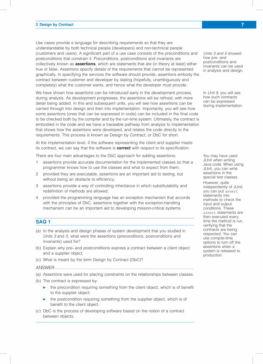
Use cases provide a language for describing requirements so that they are
understandable by both technical people (developers) and non-technical people
(customers and users). A significant part of a use case consists of the preconditions and
postconditions that constrain it. Preconditions, postconditions and invariants are
collectively known as assertions, which are statements that are (in theory at least) either
true or false. Assertions specify details of the requirements that cannot be represented
graphically. In specifying the services the software should provide, assertions embody the
contract between customer and developer by stating (hopefully, unambiguously and
completely) what the customer wants, and hence what the developer must provide.
We have shown how assertions can be introduced early in the development process,
during analysis. As development progresses, the assertions will be refined, with more
detail being added. In this and subsequent units, you will see how assertions can be
carried through into design and then into implementation. Importantly, you will see how
some assertions (ones that can be expressed in code) can be included in the final code
to be checked both by the compiler and by the run-time system. Ultimately, the contract is
embodied in the code and we have a traceable pathway from analysis to implementation
that shows how the assertions were developed, and relates the code directly to the
requirements. This process is known as Design by Contract, or DbC for short.
At the implementation level, if the software representing the client and supplier meets
its contract, we can say that the software is correct with respect to its specification.
There are four main advantages to the DbC approach for adding assertions:
1 assertions provide accurate documentation for the implemented classes so that a
programmer knows how to use the classes and what to expect from them;
2 provided they are executable, assertions are an important aid to testing, but
without being an obstacle to efficiency;
3 assertions provide a way of controlling inheritance in which substitutability and
redefinition of methods are allowed;
4 provided the programming language has an exception mechanism that accords
with the principles of DbC, assertions together with the exception-handling
mechanism can be an important aid to developing mission-critical systems.
SAQ 1
(a) In the analysis and design phases of system development that you studied in
Units 3 and 5, what were the assertions (preconditions, postconditions and
invariants) used for?
(b) Explain why pre- and postconditions express a contract between a client object
and a supplier object.
(c) What is meant by the term Design by Contract (DbC)?
ANSWER...............................................................................................................
(a) Assertions were used for placing constraints on the relationships between classes.
(b) The contract is expressed by:
c the precondition requiring something from the client object, which is of benefit
to the supplier object;
c the postcondition requiring something from the supplier object, which is of
benefit to the client object.
(c) DbC is the process of developing software based on the notion of a contract
between objects.
Units 3 and 5 showedhow pre- andpostconditions andinvariants can be usedin analysis and design.
In Unit 9, you will seehow such contractscan be expressedduring implementation.
You may have usedJUnit when writingJava code. When usingJUnit, you can writeassertions in thespecial test classes.
However, quiteindependently of JUnit,you can put assertstatements intomethods to check theinput and outputconditions. Theseassert statements arethen executed everytime the method is run,verifying that thecontracts are beingrespected. You canuse compile-timeoptions to turn off theassertions when asystem is released toproduction.
2 Design by Contract 7
2.2 How can Design by Contract help to
improve quality?
DbC complements many of the other tools that the software engineer uses to improve
quality. In this section, you will explore where DbC fits into the object-oriented
technology toolkit.
Most modern software development environments include tools that analyse code to
detect defects. That is, the tools analyse the structure of the code before it is executed.
Such tools are collectively known as static analysis tools, as they do not analyse the
dynamics of behaviour. For example, certain tools can estimate the complexity of code
using the number of lines of code and rules about the chosen implementation
language, such as the number of branching statements.
Perhaps the most effective static analysis tool in use at this time is the compiler. A
compiler will detect all syntax errors in a piece of code. Indeed, a compiler can be
made more effective in detecting defects by careful choice of programming language
features: languages that use strong typing (in the way that Java does), for instance,
constrain the programmer more, but allow the compiler to detect a wider range of
defects than just syntax errors.
An example of a dynamic tool is testing, which you will study in Unit 11. Testing can
easily occupy 40 per cent of total project effort (Pressman and Ince, 2000). Unit 11
also introduces formal technical reviews (FTRs) which, at all stages of the
development process and on all of its products, complement static analysis tools and
testing. Like testing, FTRs can cost a great deal.
There is a group of software systems known as critical systems, for which failure would
have catastrophic consequences, such as loss of life (safety-critical systems), loss of
business (business-critical systems) and failure to meet significant objectives (mission-
critical systems). It is vital that such systems be as error-free as possible, and so even
the most expensive development methods and tools can be justified. It is common in
the development of such systems to use formal methods – based on mathematical
notations, logic and proof.
Other than formal methods, which are generally only used in critical-system
development, the analysis tools mentioned above work only on the products of the
development cycle and do not link its stages – they do not provide a traceable
pathway from requirements through to code. In the quest for quality, this is a major
problem. In Unit 11, you will see that ensuring the mutual consistency of system
descriptions at different levels is a very important aspect of quality throughout
development. DbC is a cost-effective way to develop software products whose
features are traceable from the customer’s requirements.
SAQ 2
What is the important feature of DbC, which shows that it can be used to improve the
quality of a software system?
ANSWER...............................................................................................................
DbC allows the development of a software system to be traced from requirements
through to code.
In Unit 11, a defect isdefined as a verifiedlack of conformance torequirements, that is,something that shouldbe improved.
Unit 6 Interactions8
2.3 Contracts in the real world
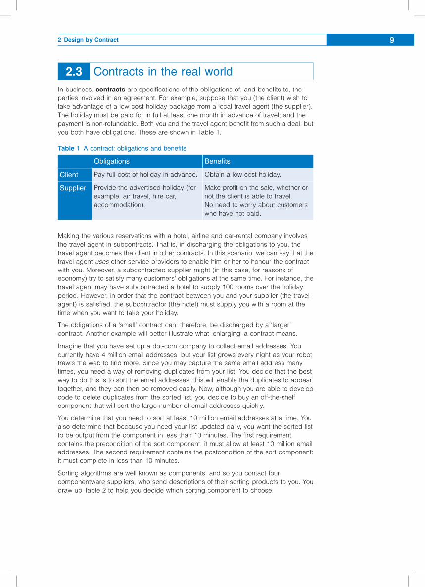
In business, contracts are specifications of the obligations of, and benefits to, the
parties involved in an agreement. For example, suppose that you (the client) wish to
take advantage of a low-cost holiday package from a local travel agent (the supplier).
The holiday must be paid for in full at least one month in advance of travel; and the
payment is non-refundable. Both you and the travel agent benefit from such a deal, but
you both have obligations. These are shown in Table 1.
Table 1 A contract: obligations and benefits
Obligations Benefits
Client Pay full cost of holiday in advance. Obtain a low-cost holiday.
Supplier Provide the advertised holiday (for
example, air travel, hire car,
accommodation).
Make profit on the sale, whether or
not the client is able to travel.
No need to worry about customers
who have not paid.
Making the various reservations with a hotel, airline and car-rental company involves
the travel agent in subcontracts. That is, in discharging the obligations to you, the
travel agent becomes the client in other contracts. In this scenario, we can say that the
travel agent uses other service providers to enable him or her to honour the contract
with you. Moreover, a subcontracted supplier might (in this case, for reasons of
economy) try to satisfy many customers’ obligations at the same time. For instance, the
travel agent may have subcontracted a hotel to supply 100 rooms over the holiday
period. However, in order that the contract between you and your supplier (the travel
agent) is satisfied, the subcontractor (the hotel) must supply you with a room at the
time when you want to take your holiday.
The obligations of a ‘small’ contract can, therefore, be discharged by a ‘larger’
contract. Another example will better illustrate what ‘enlarging’ a contract means.
Imagine that you have set up a dot-com company to collect email addresses. You
currently have 4 million email addresses, but your list grows every night as your robot
trawls the web to find more. Since you may capture the same email address many
times, you need a way of removing duplicates from your list. You decide that the best
way to do this is to sort the email addresses; this will enable the duplicates to appear
together, and they can then be removed easily. Now, although you are able to develop
code to delete duplicates from the sorted list, you decide to buy an off-the-shelf
component that will sort the large number of email addresses quickly.
You determine that you need to sort at least 10 million email addresses at a time. You
also determine that because you need your list updated daily, you want the sorted list
to be output from the component in less than 10 minutes. The first requirement
contains the precondition of the sort component: it must allow at least 10 million email
addresses. The second requirement contains the postcondition of the sort component:
it must complete in less than 10 minutes.
Sorting algorithms are well known as components, and so you contact four
componentware suppliers, who send descriptions of their sorting products to you. You
draw up Table 2 to help you decide which sorting component to choose.
2 Design by Contract 9
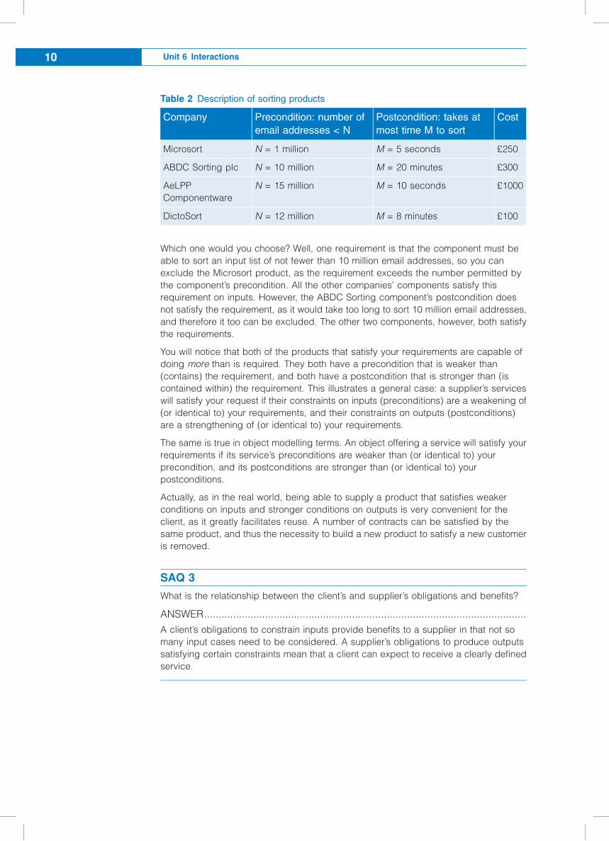
Table 2 Description of sorting products
Company Precondition: number of
email addresses < N
Postcondition: takes at
most time M to sort
Cost
Microsort N = 1 million M = 5 seconds £250
ABDC Sorting plc N = 10 million M = 20 minutes £300
AeLPP
Componentware
N = 15 million M = 10 seconds £1000
DictoSort N = 12 million M = 8 minutes £100
Which one would you choose? Well, one requirement is that the component must be
able to sort an input list of not fewer than 10 million email addresses, so you can
exclude the Microsort product, as the requirement exceeds the number permitted by
the component’s precondition. All the other companies’ components satisfy this
requirement on inputs. However, the ABDC Sorting component’s postcondition does
not satisfy the requirement, as it would take too long to sort 10 million email addresses,
and therefore it too can be excluded. The other two components, however, both satisfy
the requirements.
You will notice that both of the products that satisfy your requirements are capable of
doing more than is required. They both have a precondition that is weaker than
(contains) the requirement, and both have a postcondition that is stronger than (is
contained within) the requirement. This illustrates a general case: a supplier’s services
will satisfy your request if their constraints on inputs (preconditions) are a weakening of
(or identical to) your requirements, and their constraints on outputs (postconditions)
are a strengthening of (or identical to) your requirements.
The same is true in object modelling terms. An object offering a service will satisfy your
requirements if its service’s preconditions are weaker than (or identical to) your
precondition, and its postconditions are stronger than (or identical to) your
postconditions.
Actually, as in the real world, being able to supply a product that satisfies weaker
conditions on inputs and stronger conditions on outputs is very convenient for the
client, as it greatly facilitates reuse. A number of contracts can be satisfied by the
same product, and thus the necessity to build a new product to satisfy a new customer
is removed.
SAQ 3
What is the relationship between the client’s and supplier’s obligations and benefits?
ANSWER...............................................................................................................
A client’s obligations to constrain inputs provide benefits to a supplier in that not so
many input cases need to be considered. A supplier’s obligations to produce outputs
satisfying certain constraints mean that a client can expect to receive a clearly defined
service.
Unit 6 Interactions10
SAQ 4
(a) What does weakening a precondition mean in terms of the provision of a service?
(b) Similarly, what does strengthening a postcondition mean?
ANSWER...............................................................................................................
(a) To weaken a precondition means generalising the situation in which a service can
be provided. In general, this means that it is easier for the client to satisfy the
precondition because there are ‘fewer’ conditions to be satisfied.
(b) To strengthen a postcondition means making the service that is requested ‘better’
in terms of time, precision or some other measurable item. The precise notion of
‘better’ is not fixed, but must be considered in terms of the contract of which the
postcondition is part. It can, however, make the postcondition more difficult for the
supplier to satisfy because there are ‘more’ conditions to be satisfied.
2.4 Contracting, subcontracting and
inheritance
In Unit 3, you recorded use cases that described what tasks a software system will
carry out. A more complete documentation of a use case will emphasise what will
happen as a result of this activity, and describe the conditions that affect it. Your set of
use cases will describe the valid changes in state of the proposed software system.
One way of describing what each task, activity or operation commits to achieve is to
write a form of contract as follows:
1 a description of the task, activity or operation in question;
2 a set of constraints that are assumed to be true before you can start, which is
known as a precondition;
3 a set of constraints that must be true afterwards, which is known as a
postcondition.
The aim is to describe the state changes required of an operation, activity or task
without having to say how they might be achieved. Each contract tells you about the
constraints on the expected behaviour of an operation. In effect, the design can be
deferred while you focus on what must happen.
In the context of software development, a contract is between two objects: the client
object and the supplier object. The contract comes into effect when the client uses one
of the services that the supplier object provides – when the client object sends the
supplier object a message to invoke one of its methods. Since the client object wants
the server object to do something for it, you can view this relationship as a contract,
similar to the one we looked at above, with conditions on inputs (preconditions) and
outputs (postconditions).
As an example of how a contract works, consider a banking system in which there is a
method for withdrawing an amount of cash from an account. Assume that there is a
limit on the amount by which the account can be overdrawn. We can specify what the
method should achieve, and what should be true before the method is invoked, as a
contract with the following pre- and postconditions.
Precondition: there must be sufficient funds in the account to permit the operation
to complete without exceeding the overdraft limit.
Postcondition: the account will have been debited by the requested amount.
2 Design by Contract 11
Such pre- and postconditions place obligations on both client and supplier; in return,
they provide benefits for both.
c To satisfy the precondition, the client must ensure that the balance of the account
allows the amount to be debited without exceeding the overdraft limit; the supplier
does not need to check the balance. (In the case of software, if the client does not
respect the precondition, the supplier’s behaviour is undefined.)
c To satisfy the postcondition, the supplier must have debited the amount from the
account, and the client must have received the service that it required. If the
postcondition is not satisfied, the supplier has not provided the advertised service,
and the client has the right to complain. (In software terms, a supplier that does not
meet its postconditions when all preconditions are met is deemed incorrect.)
In practice, you might discover the appropriate contract for an operation by asking two
basic questions:
Precondition: what is needed for this operation to be allowed to start?
Postcondition: what will have happened as a result of this operation?
In the process of answering these questions, you might discover new classes,
attributes or associations, and will have to amend your models accordingly. For
example, for a client of the above-described bank account class to respect the
precondition, it must be able to find out what the overdraft limit and current balance for
the account are, which might imply the addition of an attribute, operation or
association.
Subcontracting and inheritance
When we examined the generalisation relationship in Unit 5, we emphasised the use of
the substitutability test to determine whether one object was a generalisation of
another. If an object of one type can be substituted for an object of another type in all
circumstances, then the type of the first object is a subtype of the second; that is, the
second object is a generalisation of the first. In contracting terms, this means that if the
object objA is an instance of the class A and the object objB is an instance of the class
B, where B is a subclass of A, then objB can be substituted for objA, and must satisfy
any contracts that objA may be involved in, without clients being affected. A client of
objA will be expecting a certain contract – it expects that if the precondition is met, the
postcondition will be met. The substitution of objB for objA must not affect this contract
– it must still be honoured.
When we come to examine the idea of subcontracts in software, we must bear in mind
that objects relate to one another in two basic ways:
c through associations;
c through generalisations.
It turns out that an important relationship must exist between the operations of a class
and the operations of its subclass if the objects of the subclass are to be substitutable
for those of the parent class. This relationship can be expressed in terms of the pre-
and postconditions associated with the equivalent methods in the two classes. The
subclass must neither strengthen the precondition (make the precondition more
restrictive) nor weaken the postcondition (deliver less service). You will explore this
idea in more detail in Unit 9, when we move from design to implementation – where
operations become methods.
Unit 6 Interactions12
Constraints on behaviour
In the domain of a lending library, you might identify two basic use cases:
c borrow a book;
c return a book.
In the case of borrowing a book, you expect to record a new loan while making sure
that the member does not exceed the allowance of three books on loan. The ‘contract’
between the member and the library to ‘borrow a book’ is constrained as follows.
Precondition: the number of books currently on loan to this library member is less
than 3 (otherwise the book cannot be taken out).
Postcondition: the number of books currently on loan to this library member will
have been increased by 1; the library member will have been linked to a new loan;
the book will have been linked to the same new loan.
A software system for such a lending library would be expected to support the
borrowing and returning of books. During the design activity, you would develop a
class model that meets the contractual requirements of each use case. Each pre- and
postcondition must be translated into your design. For object-oriented systems, this
means that you will be constraining the behaviour of the system in terms of:
c objects that are created and/or destroyed;
c links between objects that are created and/or destroyed;
c attributes whose values are changed.
For example, if you chose to have a class called Loan to represent the relationship
between library members and the books that they borrow, you would have to consider
the consequences of creating each new Loan object in terms of how it relates to other
objects.
SAQ 5
(a) Under what circumstances is one object, obj1 of class A, say, substitutable for
another, obj2 of class B, say?
(b) What three sets of items should you examine to help you find suitable
postconditions when identifying the possible operations for a class?
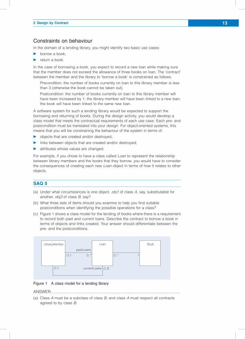
(c) Figure 1 shows a class model for the lending of books where there is a requirement
to record both past and current loans. Describe the contract to borrow a book in
terms of objects and links created. Your answer should differentiate between the
pre- and the postconditions.
Figure 1 A class model for a lending library
ANSWER...............................................................................................................
(a) Class A must be a subclass of class B, and class A must respect all contracts
agreed to by class B.
0..*
LibraryMember
pastLoans
currentLoans
Loan Book
0..3
0..*0..1 1
0..1
2 Design by Contract 13
(b) You should investigate the following three sets of items when searching for the
possible postconditions for an operation:
c instances of a class (its objects) that have been created or deleted;
c instances of associations (links) that have been formed or broken;
c attributes that have been modified.
(c) The contract between the library member and the library to borrow a book is
constrained as follows.
Precondition:
there must be an instance of the class LibraryMember that corresponds to the
real-world member;
there must be an instance of the class Book that corresponds to the real-world
book that the member wants to borrow;
the instance of the class LibraryMember must be linked to fewer than 3
instances of the class Loan in the role of currentLoans.
Postcondition:
a new instance of the class Loan will have been created; the instance of the
class LibraryMember will have been linked to the new instance of Loan in the
role of currentLoans;
the instance of the class Book will have been linked to the same new instance
of the class Loan.
Exercise 1
Consider the contract for a premium-rate, 24-hour courier service in which compensation
is paid for non-delivery within 24 hours.
(a) Show in a table the obligations and benefits of the client and supplier of this service.
(b) Give the pre- and postconditions.
Solution.................................................................................................................
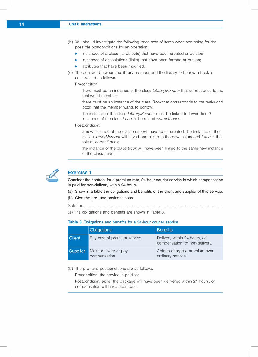
(a) The obligations and benefits are shown in Table 3.
Table 3 Obligations and benefits for a 24-hour courier service
Obligations Benefits
Client Pay cost of premium service. Delivery within 24 hours, or
compensation for non-delivery.
Supplier Make delivery or pay
compensation.
Able to charge a premium over
ordinary service.
(b) The pre- and postconditions are as follows.
Precondition: the service is paid for.
Postcondition: either the package will have been delivered within 24 hours, or
compensation will have been paid.
Unit 6 Interactions14
Exercise 2
Look at Figure 1 again, and identify the pre- and postconditions for returning a book to
the library. Include the fact that there are two significant dates for each loan in relation to
the possible payment of fines:
c an expected return date;
c an actual return date.
Assume that the value of the expected return date will have been set as part of
borrowing a book. Also assume that the actual return date will be recorded as an
attribute of a loan (to enable you to deal with charging for overdue books at some later
stage of the development).
Solution.................................................................................................................
In Figure 1, the class Loan has two associations with the class LibraryMember, to
differentiate between current and past loans. The contract for returning a book can be
expressed as follows.
Precondition: the instance of the class LibraryMember is linked to an instance of the
class Loan in the role of currentLoans;
Postcondition:
the link between the instance of the class LibraryMember and the instance of the
class Loan in the role of currentLoans will have been broken;
the instance of the class LibraryMember will have been linked to the same instance
of the class Loan in the role of pastLoans;
a value will have been set for the attribute actualReturnDate in the same instance
of class Loan.
Note that the association between the class Loan and the class Book is not affected by
returning a book. The instance of the class Book is linked to the instance of the class
Loan before and after its return.
2.5 Summary of section
In this section, you have:
c reviewed how assertions are used in classes and operations at the analysis and
design stages of development;
c learnt how using assertions in this way can be seen as expressing a client–supplier
contract between the objects of an object-oriented system;
c learnt how the process of using assertions in this way, called Design by Contract
(DbC), can be applied during analysis;
c examined the notion of a contract, and its benefits and obligations to clients and
suppliers, in both business and software terms;
c seen how preconditions and postconditions must be respected when one type is a
subtype of another;
c seen that the behaviour of a task or operation can be constrained by identifying the
conditions that must be true before and after the given task or operation.
2 Design by Contract 15
3 Starting dynamic modelling
This section shows you how to model the dynamic behaviour of objects from your static
class models, so that you can decide which operations will be allocated to which
classes.
3.1 Focusing on a solution
So far you have seen how to build class models and how to capture requirements in
the form of use cases and activity diagrams. Although we covered these by looking at
use cases first, we explained that they are naturally developed in parallel. A class
model alone merely describes the structure of things; it says nothing about how they
should behave. A set of use cases without a class model to constrain the vocabulary
used will suffer from all the problems of informal specification, open to numerous
interpretations of what the words mean.
However you order the development process, you should eventually reach a stage of
having a precise class model identifying the classes and their relationships, together
with some use cases describing what a system is intended to accomplish. What you
do not yet have is a way of linking the two together. The classes do not contain
complete lists of operations and attributes, and the use cases do not say which
classes should be responsible for which parts of the computation. You have
concentrated on the static modelling of the system. Now you need to do some
dynamic modelling, to show how the objects interact by sending messages to
implement the required functionality of the software system.
Dynamic modelling requires you to make some decisions about which classes contain
the operations needed to carry out which parts of the overall use case. The point
where you start making these decisions is the beginning of design. This certainly fits
the suggested distinction that analysis is about describing a real-world domain that
you are to accurately record – we are describing what there is, not what we want to
build. However, when we start design, we are talking about software and programs.
There are many decisions (choices) to be made during design.
Sequence diagrams and communication diagrams (known collectively as interaction
diagrams) are notations to help make and record decisions relating to the behaviour
defined for each class. On an interaction diagram, objects are shown exchanging
messages. An object sending a message to another object is represented using an
arrow labelled with the message. A sequence diagram shows the flow of messages
from object to object as time passes by. A communication diagram shows the objects
and their links (the structure). It shows the flow of messages as they pass along the
links between objects. The two diagrams are equivalent: what can be shown in one
can be shown in the other.
Although interaction diagrams are sometimes presented as simply documenting the
mechanics of an implementation, it is the act of building them that is at the very heart
of object-oriented design. Every time you draw an arrow on an interaction diagram,
showing one object requesting services from another, you are committing the class of
the receiver to provide an operation with a particular name. When you have completed
a set of interaction diagrams, you will have built interface specifications for the classes
in almost enough detail to hand over for coding.
Communicationdiagrams are alsoknown by their UML1.5 name: collaborationdiagrams.
Unit 6 Interactions16
Communication diagrams and sequence diagrams are used for similar purposes,
although they emphasise different features. Communication diagrams make the
interconnections between objects clear, but the actual sequence of messages can be
difficult to see. In practice, a numbering system is needed to identify which message
comes first, which comes second, and so on. Sequence diagrams make the time
relationship extremely clear, but it may not be easy to see overall patterns of message
flow, as each diagram shows only the objects involved in a particular sequence. We
will consider sequence diagrams first.
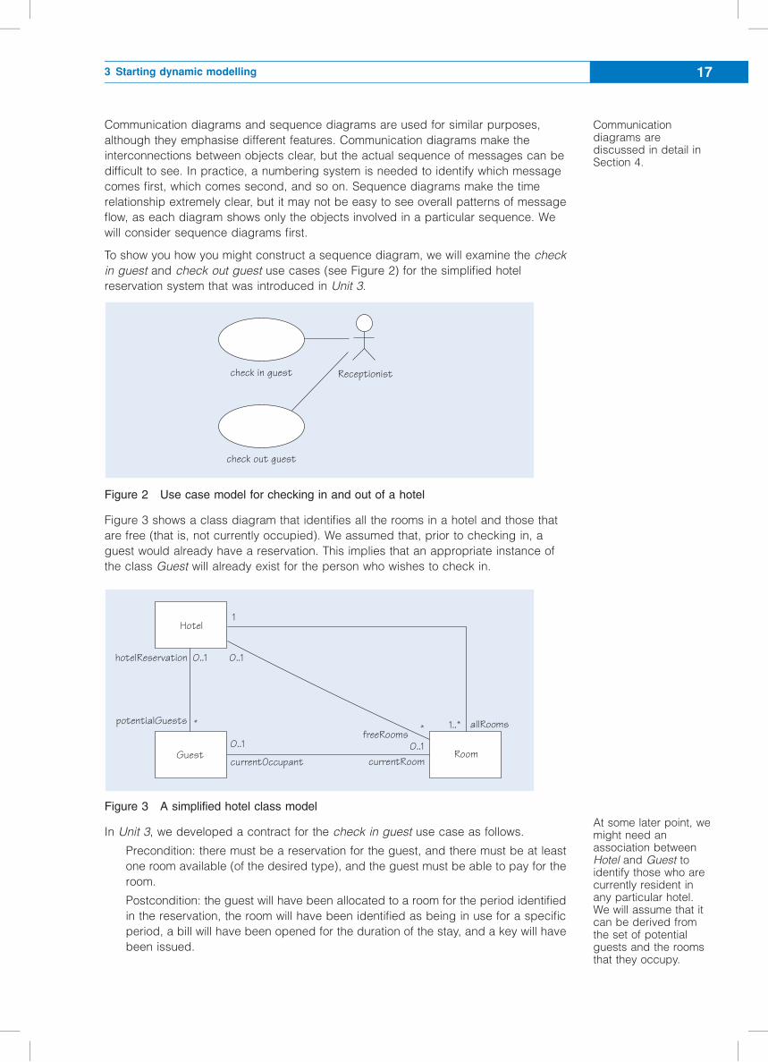
To show you how you might construct a sequence diagram, we will examine the check
in guest and check out guest use cases (see Figure 2) for the simplified hotel
reservation system that was introduced in Unit 3.
Figure 2 Use case model for checking in and out of a hotel
Figure 3 shows a class diagram that identifies all the rooms in a hotel and those that
are free (that is, not currently occupied). We assumed that, prior to checking in, a
guest would already have a reservation. This implies that an appropriate instance of
the class Guest will already exist for the person who wishes to check in.
Figure 3 A simplified hotel class model
In Unit 3, we developed a contract for the check in guest use case as follows.
Precondition: there must be a reservation for the guest, and there must be at least
one room available (of the desired type), and the guest must be able to pay for the
room.
Postcondition: the guest will have been allocated to a room for the period identified
in the reservation, the room will have been identified as being in use for a specific
period, a bill will have been opened for the duration of the stay, and a key will have
been issued.
Receptionistcheck in guest
check out guest
Hotel
Guest
1
0..1
0..1
currentOccupantRoom
* 1..**
currentRoom
freeRoomsallRooms
0..1
potentialGuests
hotelReservation 0..1
Communicationdiagrams arediscussed in detail inSection 4.
At some later point, wemight need anassociation betweenHotel and Guest toidentify those who arecurrently resident inany particular hotel.We will assume that itcan be derived fromthe set of potentialguests and the roomsthat they occupy.
3 Starting dynamic modelling 17
We will assume the receptionist issues the key, and not deal with it further here. If we
also assume that bills are part of a separate accounting package, we can use the
simplified class model in Figure 3 to define the check in guest use case as follows.
Precondition:
the instance of the class Guest is linked to an instance of the class Hotel in the role
of hotelReservation;
for the same instance of the class Hotel, there is at least one link to an instance of
the class Room in the role of freeRooms.
Postcondition:
the link between the instance of the class Hotel and the instance of the class Room
in the role of freeRooms will have been broken;
the same instance of the class Room (in the role of currentRoom) will have been
linked to the instance of the class Guest in the role of currentOccupant.
(If you were to set about designing a sequence diagram, you might start with the
particular configuration shown in Figure 4 which shows that the object jill : Guest
already exists.)
SAQ 6
(a) What is the difference in emphasis between sequence diagrams and
communication diagrams?
(b) How is time represented in a communication diagram?
(c) What obligation is placed on an object that is sent a message?
ANSWER...............................................................................................................
(a) Sequence diagrams emphasise the flow of messages from object to object over
time. Communication diagrams emphasise the message traffic across the links in a
particular configuration of objects.
(b) Time is represented by the sequential numbering of messages (see Section 4).
(c) The class of the receiving object is committed to implement an operation with a
particular name and argument signature.
3.2 Starting to build a sequence diagram
Although not all interaction diagrams correspond to use cases (some are produced
simply in the design of complex methods), we begin by looking at interactions implied
by use cases. A use case specifies how a change of state of a system takes place.
A sequence diagram represents the ripple of messages that brings about that change
of state.
A use case is usually written to describe a general business-level operation on the
system. For instance, the use cases for checking in and checking out are shown
(simplified) in Figure 2. Although you must build software that can check in any guest,
it is very often much more helpful to consider scenarios for specific situations. For
example, how would your system allow Jill to check in and then occupy room 401?
Once you have a detailed understanding of how you propose to handle some specific
cases, you will be in a better position to claim that you can handle the general case.
Choosing which scenarios to handle is similar to choosing test data. You choose some
typical situations and some borderline ones. When exploring how guests check in to a
You may already havediscovered the specificscenarios and cases ifyou have used activitydiagrams to investigatethe scenarios for theuse cases.
Unit 6 Interactions18
hotel, you might explore the scenarios where jill checks in to theRitz, which has three
rooms, of which:
1 one is occupied;
2 two are occupied (she takes the last room);
3 all three are occupied (there is no free room).
Once you are clear that you can handle these specific situations, you might be in a
position to claim that you can handle the general case.
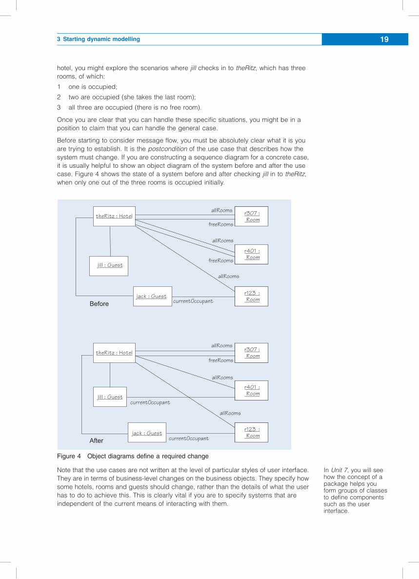
Before starting to consider message flow, you must be absolutely clear what it is you
are trying to establish. It is the postcondition of the use case that describes how the
system must change. If you are constructing a sequence diagram for a concrete case,
it is usually helpful to show an object diagram of the system before and after the use
case. Figure 4 shows the state of a system before and after checking jill in to theRitz,
when only one out of the three rooms is occupied initially.
Figure 4 Object diagrams define a required change
Note that the use cases are not written at the level of particular styles of user interface.
They are in terms of business-level changes on the business objects. They specify how
some hotels, rooms and guests should change, rather than the details of what the user
has to do to achieve this. This is clearly vital if you are to specify systems that are
independent of the current means of interacting with them.
theRitz : HotelfreeRooms
r307 :allRooms
jill : GuestfreeRooms
allRooms
theRitz : HotelfreeRooms
allRooms
allRooms
allRooms
allRooms
?&'14&
>'6&4
currentOccupantjack : Guest
jack : GuestcurrentOccupant
jill : GuestcurrentOccupant
Room
r401 :Room
r123 :Room
r307 :Room
r401 :Room
r123 :Room
In Unit 7, you will seehow the concept of apackage helps youform groups of classesto define componentssuch as the userinterface.
3 Starting dynamic modelling 19

You need to capture what checking in is about, regardless of whether interacting with
the system is via a keyboard, a microphone or the internet. Figure 5 is an example of
an early model that you might draw when thinking about the eventual form of the user
interface. It shows that the business model (Hotel, Room and so on) has very little
connection to the user interface. You are about to design the business-model
interactions, but you have to be aware that an interaction is triggered by a message
from a user interface.
Figure 5 The separation between the business model and the user interface
To construct a sequence diagram, we need to know where the first message in the use
case originates. It will normally come from a user interface. At this point we are not
concerned with any of the details of this interface; we just need to know that it exists
and that a user can initiate a use case from it, causing a message to be sent to one of
the business objects. Figure 5 shows the class diagram with a hypothetical user-
interface class that can originate messages.
SAQ 7
(a) How does the use of a pair of object diagrams help you prepare to build a
sequence diagram?
(b) Is the initial message on an interaction diagram always sent from an object
representing the user interface?
ANSWER...............................................................................................................
(a) The aim is to show how a given postcondition can be achieved in a sequence
diagram. A pair of object diagrams, showing the states before and after the
operation in question, identifies the changes in system state that take place in
order to meet the postcondition.
(b) No – we are not constrained to showing interactions with the user interface.
Message sequences can originate from any object. The user interface is the origin
for those messages that relate to a use case scenario, which we have described in
the case of checking guests in to a hotel. However, interaction diagrams can
become very complex if we try to show all the possible messages for a given
configuration of objects. Following the principle of modularisation, we would split
up a complex interaction into a number of smaller ones. In the new diagrams, the
starting point need not be the user interface.
CheckInScreen
Hotel
1
1..*
*freeRooms
allRooms
Room
1
component ofthe user interfacefor the hotel
find out about other possibleassociations (to Room orGuest)
Unit 6 Interactions20
3.3 Assigning responsibilities in design
In design, we must make choices about which responsibility should be assigned to
which class. Ultimately, any choice should be justified in terms of guiding design
principles such as encapsulation, low coupling and high cohesion.
Craig Larman has defined a collection of patterns based on such principles, to help
designers assign responsibilities in commonly occurring design scenarios (Larman,
2002). While the principles provide general guidance, the patterns provide practical
advice on how to solve design problems based on those principles. Larman calls such
patterns GRASP, an acronym for General Responsibility Assignment Software
Patterns. Here we present two of these patterns: Expert and Creator.
GRASP Expert
The GRASP Expert (also known as Information Expert) pattern addresses the problem
of distributing responsibilities for knowing across the system, in particular, for
information that should be derived from object properties. The fulfilment of a
responsibility within a system often requires the consolidation of information that is
distributed among several different objects, each being knowledgeable or being an
‘expert’ on some aspect of such information. The Expert pattern allows you to distribute
responsibilities among ‘information experts’ in a way that encourages cohesive class
definitions, which are easier to understand and maintain.
The Expert pattern, like many aspects of object technology, has a real-world analogy.
Within organisations, responsibility to fulfil a task is commonly given to teams of
individuals who collectively have the necessary expertise. And just as software objects
may need to collaborate, because information is distributed among classes, so it is
with team members, who need to interact and cooperate with one another to fulfil their
task.
The pattern can be summarised as follows.
Name Expert
Intent To assign responsibility based on object properties.
How it works The responsibility is assigned to the class that has the information
necessary to fulfil that responsibility – the ‘information expert’; this information is
represented by the properties of the object of the class.
When to use it Use this pattern when you need to decide which of a number of
interacting objects a responsibility should be assigned to. The pattern maximises
encapsulation, as objects use their own information to fulfil a task. Therefore it
enhances low coupling and high cohesion within a system.
Example An information expert could be an object representing a sale, to which
the responsibility of calculating the total based on the sale items within that sale
can be assigned.
GRASP Creator
The fulfilment of a responsibility will often require the creation and initialisation of new
objects. The GRASP Creator pattern is used to assign responsibilities related to the
creation of objects. Its objective is to find a creator that needs to be linked to the
created object, because the creator aggregates, maintains or records, or contains the
created object. Sometimes we find a creator class by looking for the class that has the
responsibility for providing the initialising data that will be used during creation.
3 Starting dynamic modelling 21
The pattern can be summarised as follows.
Name Creator
Intent To assign responsibility for creating objects.
How it works The responsibility for creating an instance of some class is assigned
to the class that aggregates, maintains or records or contains instances of the
class of the newly created object, especially if the creator class provides the data
required to initialise the newly created object.
When to use it Use this pattern whenever you need to assign responsibilities for
object creation. Low coupling is maintained between the creator class and the class
of the created object, because the latter is probably already linked to the creator
class owing to the existing associations that motivated its choice as the creator.
Example A creator could represent a bank, with the newly created object being a
bank account. In this case, the creator might be responsible for assigning the
account number to the newly created bank account. Another example is a creator
representing an order, with the newly created object being an order item. In this case,
the creator and its associated created objects might be viewed as a composition.
You will have an opportunity to apply GRASP later on in this chapter. Before we do that,
however, we need to introduce sequence diagrams.
3.4 Sequence-diagram notation
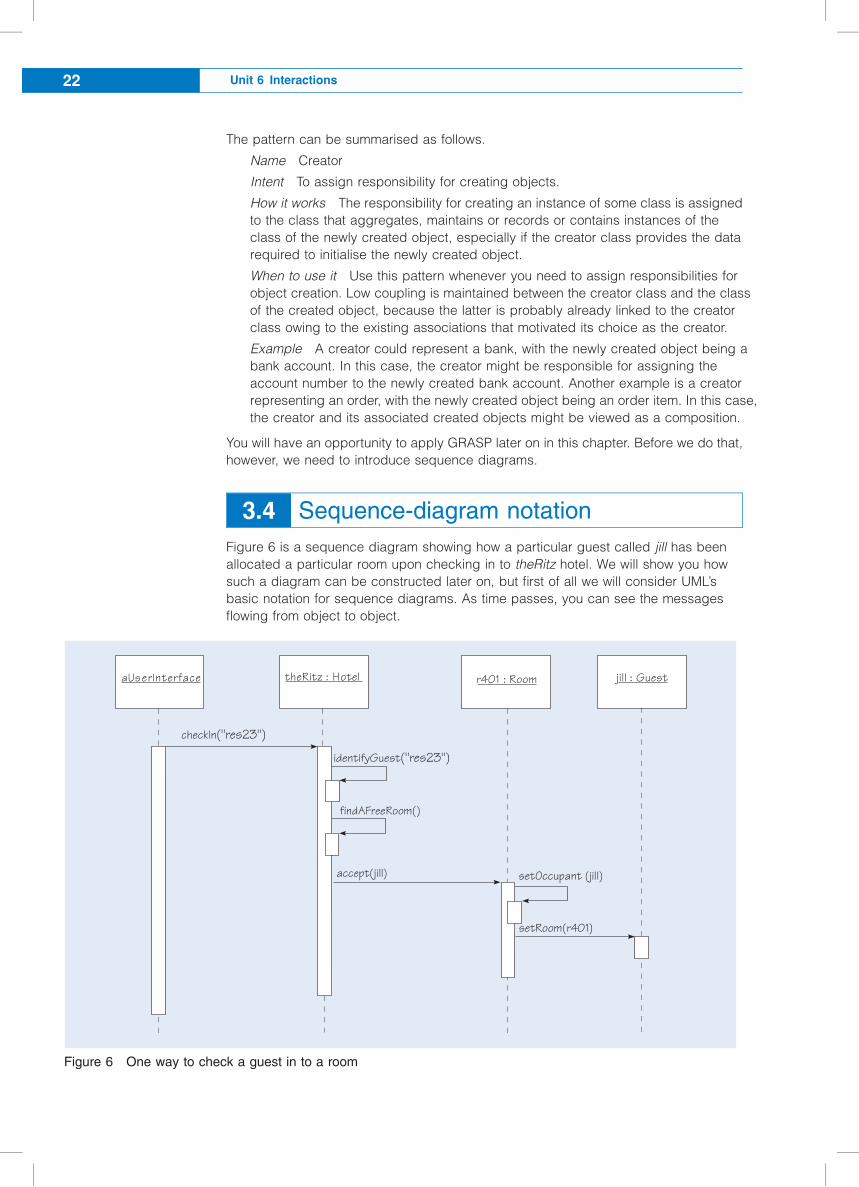
Figure 6 is a sequence diagram showing how a particular guest called jill has been
allocated a particular room upon checking in to theRitz hotel. We will show you how
such a diagram can be constructed later on, but first of all we will consider UML’s
basic notation for sequence diagrams. As time passes, you can see the messages
flowing from object to object.
Figure 6 One way to check a guest in to a room
checkIn("res23")
aUserInterface
findAFreeRoom()
accept(jill) setOccupant (jill)
setRoom(r401)
theRitz : Hotel r401 : Room jill : Guest
identifyGuest("res23")
Unit 6 Interactions22
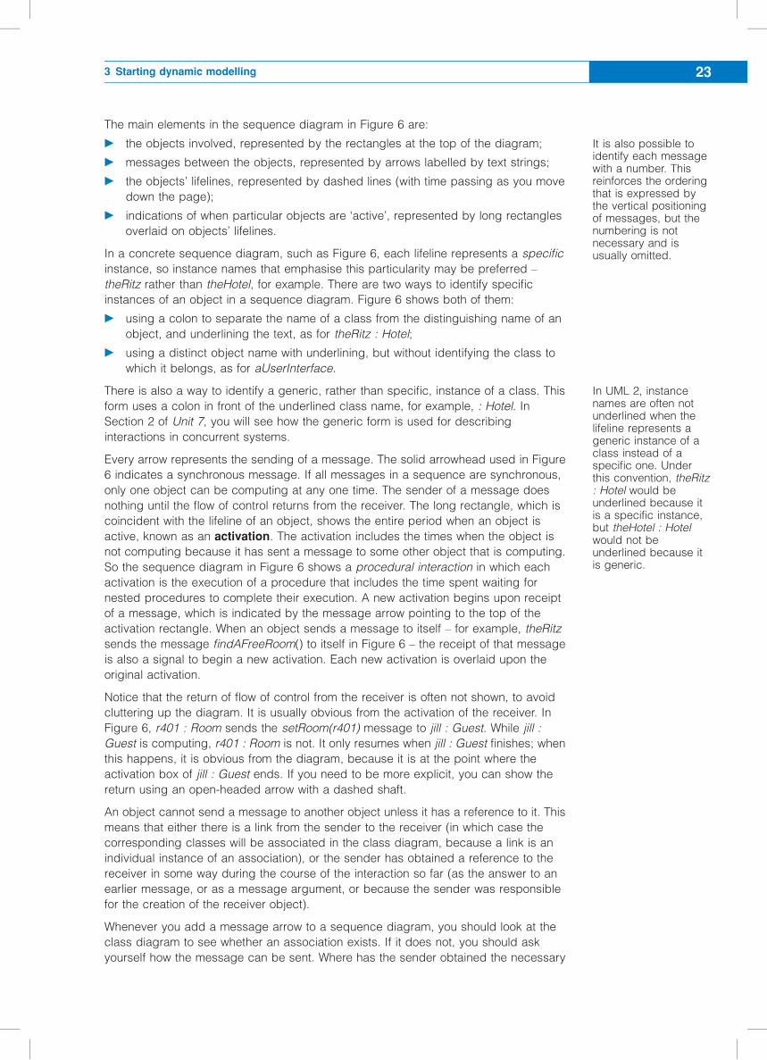
The main elements in the sequence diagram in Figure 6 are:
c the objects involved, represented by the rectangles at the top of the diagram;
c messages between the objects, represented by arrows labelled by text strings;
c the objects’ lifelines, represented by dashed lines (with time passing as you move
down the page);
c indications of when particular objects are ‘active’, represented by long rectangles
overlaid on objects’ lifelines.
In a concrete sequence diagram, such as Figure 6, each lifeline represents a specific
instance, so instance names that emphasise this particularity may be preferred –
theRitz rather than theHotel, for example. There are two ways to identify specific
instances of an object in a sequence diagram. Figure 6 shows both of them:
c using a colon to separate the name of a class from the distinguishing name of an
object, and underlining the text, as for theRitz : Hotel;
c using a distinct object name with underlining, but without identifying the class to
which it belongs, as for aUserInterface.
There is also a way to identify a generic, rather than specific, instance of a class. This
form uses a colon in front of the underlined class name, for example, : Hotel. In
Section 2 of Unit 7, you will see how the generic form is used for describing
interactions in concurrent systems.
Every arrow represents the sending of a message. The solid arrowhead used in Figure
6 indicates a synchronous message. If all messages in a sequence are synchronous,
only one object can be computing at any one time. The sender of a message does
nothing until the flow of control returns from the receiver. The long rectangle, which is
coincident with the lifeline of an object, shows the entire period when an object is
active, known as an activation. The activation includes the times when the object is
not computing because it has sent a message to some other object that is computing.
So the sequence diagram in Figure 6 shows a procedural interaction in which each
activation is the execution of a procedure that includes the time spent waiting for
nested procedures to complete their execution. A new activation begins upon receipt
of a message, which is indicated by the message arrow pointing to the top of the
activation rectangle. When an object sends a message to itself – for example, theRitz
sends the message findAFreeRoom() to itself in Figure 6 – the receipt of that message
is also a signal to begin a new activation. Each new activation is overlaid upon the
original activation.
Notice that the return of flow of control from the receiver is often not shown, to avoid
cluttering up the diagram. It is usually obvious from the activation of the receiver. In
Figure 6, r401 : Room sends the setRoom(r401) message to jill : Guest. While jill :
Guest is computing, r401 : Room is not. It only resumes when jill : Guest finishes; when
this happens, it is obvious from the diagram, because it is at the point where the
activation box of jill : Guest ends. If you need to be more explicit, you can show the
return using an open-headed arrow with a dashed shaft.
An object cannot send a message to another object unless it has a reference to it. This
means that either there is a link from the sender to the receiver (in which case the
corresponding classes will be associated in the class diagram, because a link is an
individual instance of an association), or the sender has obtained a reference to the
receiver in some way during the course of the interaction so far (as the answer to an
earlier message, or as a message argument, or because the sender was responsible
for the creation of the receiver object).
Whenever you add a message arrow to a sequence diagram, you should look at the
class diagram to see whether an association exists. If it does not, you should ask
yourself how the message can be sent. Where has the sender obtained the necessary
It is also possible toidentify each messagewith a number. Thisreinforces the orderingthat is expressed bythe vertical positioningof messages, but thenumbering is notnecessary and isusually omitted.
In UML 2, instancenames are often notunderlined when thelifeline represents ageneric instance of aclass instead of aspecific one. Underthis convention, theRitz: Hotel would beunderlined because itis a specific instance,but theHotel : Hotelwould not beunderlined because itis generic.
3 Starting dynamic modelling 23
reference? If the sender does not have the required reference, you must rethink the
message sequence.
An object may send messages to itself, as well as to other objects. It is possible to use
an interaction diagram to show those messages that an object sends to itself in
response to some other message. However, if we showed every message from an
object to itself, we might soon have a very busy diagram in our attempts to model a
particular computation. Therefore we usually restrict ourselves to those messages that
are traceable to the pre- and postconditions in the use cases. Figure 6 shows two
examples that are traceable to the pre- and postconditions for the check in guest use
case. In the first example, the operation findAFreeRoom shows which class will be
responsible for finding a suitable room for a new guest – part of the precondition. In the
second, we see that each instance of the class Room keeps a reference to the
instance of Guest using the operation setOccupant(jill) – part of the postcondition.
In the next subsection, you will how the sequence diagram in Figure 6 was
constructed.
SAQ 8
(a) In an interaction diagram, which class must provide the operation indicated by a
message passed from one object to another?
(b) What does a lifeline represent?
(c) What does the box at the top of a lifeline include?
(d) What sort of arrowhead is used on an arrow depicting synchronous message-
sending?
(e) What is a procedural interaction? With what might it be contrasted?
(f) In a sequence diagram, what does the widening of a lifeline into a tall, thin
rectangle mean?
ANSWER...............................................................................................................
(a) The class of the receiver object must provide the appropriate operation.
(b) A lifeline represents the portion of the life of an object covered by the sequence
diagram.
(c) It includes an instance name, optionally followed by a colon and a class name, or,
for a generic object, just a colon and a class name. For example, objectname,
objectName : ClassName and : Classname are all allowed.
(d) A solid black arrowhead, which indicates that the interaction is procedural. Note
that an open or stick arrowhead with a dashed shaft is used to signify the method’s
return, although it is often omitted for clarity. (See Unit 7 for a list of permitted arrow
styles.)
(e) It is an interaction in which the sender of a message is blocked until the receiver of
the message has finished processing. This is exactly the same as what is
sometimes called subroutine semantics. It is the usual policy when a single thread
of control is allowed. If multiple threads are allowed, we might not want the sender
of the message to block, in which case we could start a concurrent activity.
(f) This shows that the object is active. An object is said to be active if it is either
performing an operation or awaiting completion of an operation that it has
requested another object to perform.
Unit 6 Interactions24
3.5 Designing with sequence diagrams
The first two design decisions to be made relate to the very first message that starts
the internal sequence of messages that produces the required postcondition. The
same applies whether you are constructing a sequence diagram or a communication
diagram. Figure 6 shows the initial message coming from an object identified as
aUserInterface. This message will have been initiated in some way by a hotel
receptionist. There must be some way of identifying the reservation involved, so that
the software can locate the corresponding Guest object, and we have assumed for
now that this will be done by passing a string identifier from the user interface. In
Figure 6, the identifier is "res23".
When making the first design decision, namely what the very first message should be,
you are committing whoever builds the user interface to ensuring that the program
sends that message. The interaction shown in Figure 6 commits whoever builds the
user interface to making it send a message with the form checkIn(String).
The second decision to be made relates to where the initial message should be sent.
In Figure 6, the initial message is sent to the object theRitz. By sending this message
to a Hotel, you commit the class Hotel to implementing this functionality, which is
shown in Figure 6 by the internal message identifyGuest("res23"). Of course, you could
have chosen another object to receive the message. Some reasonable choices for our
example are as follows:
c checkIn("res23") sent to theRitz : Hotel – this choice, the one shown in Figure 6, is
consistent with the GRASP Expert pattern: the hotel is the overall expert in how the
hotel is managed;
c checkIn("res23") sent to some ‘system’ object that represents the whole system –
this choice is similar to the previous one, in which the instance of Hotel represents
the system;
c checkIn("res23") sent to some CheckerIn object belonging to a new class we
define specially to provide the functionality for this use case.
Each of the above is a plausible decision. We will return to consider their respective
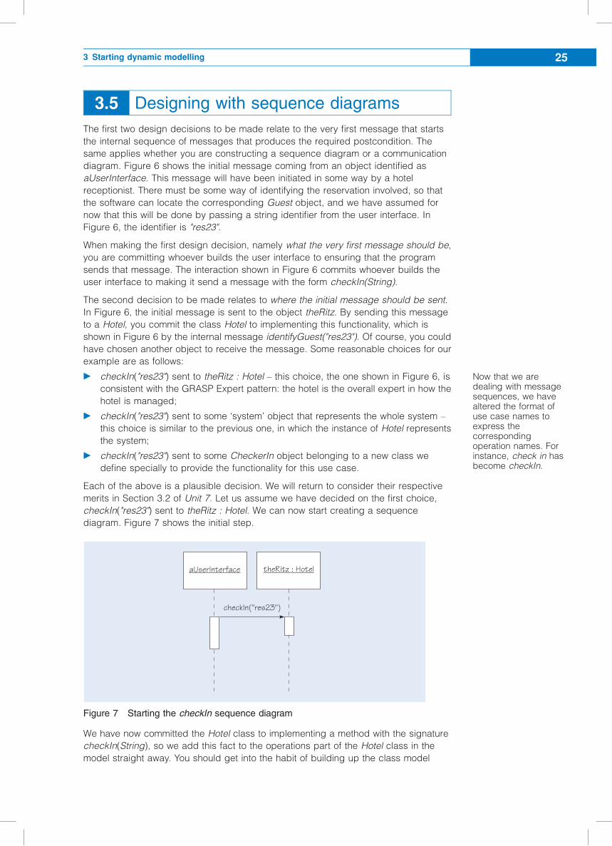
merits in Section 3.2 of Unit 7. Let us assume we have decided on the first choice,
checkIn("res23") sent to theRitz : Hotel. We can now start creating a sequence
diagram. Figure 7 shows the initial step.
Figure 7 Starting the checkIn sequence diagram
We have now committed the Hotel class to implementing a method with the signature
checkIn(String), so we add this fact to the operations part of the Hotel class in the
model straight away. You should get into the habit of building up the class model
checkIn("res23")
aUserInterface theRitz : Hotel
Now that we aredealing with messagesequences, we havealtered the format ofuse case names toexpress thecorrespondingoperation names. Forinstance, check in hasbecome checkIn.
3 Starting dynamic modelling 25
incrementally, as you make and record each successive decision about an operation
and its location.
Next we have to identify the guest associated with a particular reservation identifier,
find a room that is empty, and allocate it to that guest. We could assign the overall
responsibility for this to the Hotel object, which would coordinate the search for a room
and its allocation to the intended guest, namely the object jill : Guest. Another
approach would be to delegate some of the behaviour to the Room objects, perhaps
giving them an operation attemptToHouse(g : Guest). Each room would know whether
or not it was free and how to accommodate a Guest. If a given room could not
accommodate a Guest, it would return an appropriate indicator, so that the next room
could be tried.
However, let us suppose we decide that the Hotel should do the work of finding the
guest and allocating the room. Since the Hotel needs to identify the guest associated
with a particular reservation, we now have to decide how that will be done. The class
model in Figure 3 shows that a Hotel has an association with a Guest, identified by the
role names hotelReservation and potentialGuests. According to the GRASP Expert
pattern, Hotel would be the expert for guests associated with the hotel, so we assign
the operation to Hotel. At this stage we probably would not want to describe in detail a
particular algorithm for identifying the actual Guest object, but we commit Hotel to
providing an operation identifyGuest("res23"), which returns a single instance of the
class Guest, without making any statement for now about how this method will be
implemented. In the sequence diagram, we can show theRitz : Hotel sending a
message to itself to invoke this operation.
If the Hotel needs to find a room in order to house a guest, we must decide how to find
a room. Since the class model shows that Hotel has an association with Room,
identified by the role name freeRooms, we know that the hotel is the expert in free
rooms at the hotel and can use that. As with identifying the guest, we might not want to
describe in detail a particular algorithm for choosing and allocating a free room. So we
simply commit Hotel to providing an operation findAFreeRoom, which returns one room
– a single instance of the Room class. In the sequence diagram we can show theRitz :
Hotel sending a message to itself to invoke this operation. We need to specify what this
method does – its pre- and postconditions. For example, does this method just find
one of the free rooms, or does it also remove the room it found from the freeRooms
association? Suppose that it does the latter. While you are drawing the sequence
diagram, you can add the pre- and postconditions for the operation, as well as
comments for the developers who will implement your design.
Now that the Hotel object has both a room and a guest to occupy it, which object will
be responsible for installing the guest in the room? All the processing could be done in
the Hotel, or the Room could accept the Guest, or the Guest could install themselves
in the Room. Suppose you choose to make the Room responsible. The Hotel can send
the message accept(jill) to r401 : Room. But what should the accept operation do?
According to Figure 6, r401 needs to know the guest who occupies it (jill), and jill
needs to know the room that is allocated (r401). We can represent this by making the
Room invoke an operation on itself to set its occupant, and then send a message to
inform the occupant which room they have been allocated.
All the design decisions that led to the final sequence diagram shown in Figure 6 have
now been discussed. As a result of all these decisions, you are now committed to the
operations shown in Table 4.
For now, we areworking with twoassumptions: first, thatthe associationbetween Room andGuest is navigable inboth directions;second, that theoperationfindAFreeRoomremoves the Room itfinds from thefreeRooms role, asshown in Figure 4.
Unit 6 Interactions26
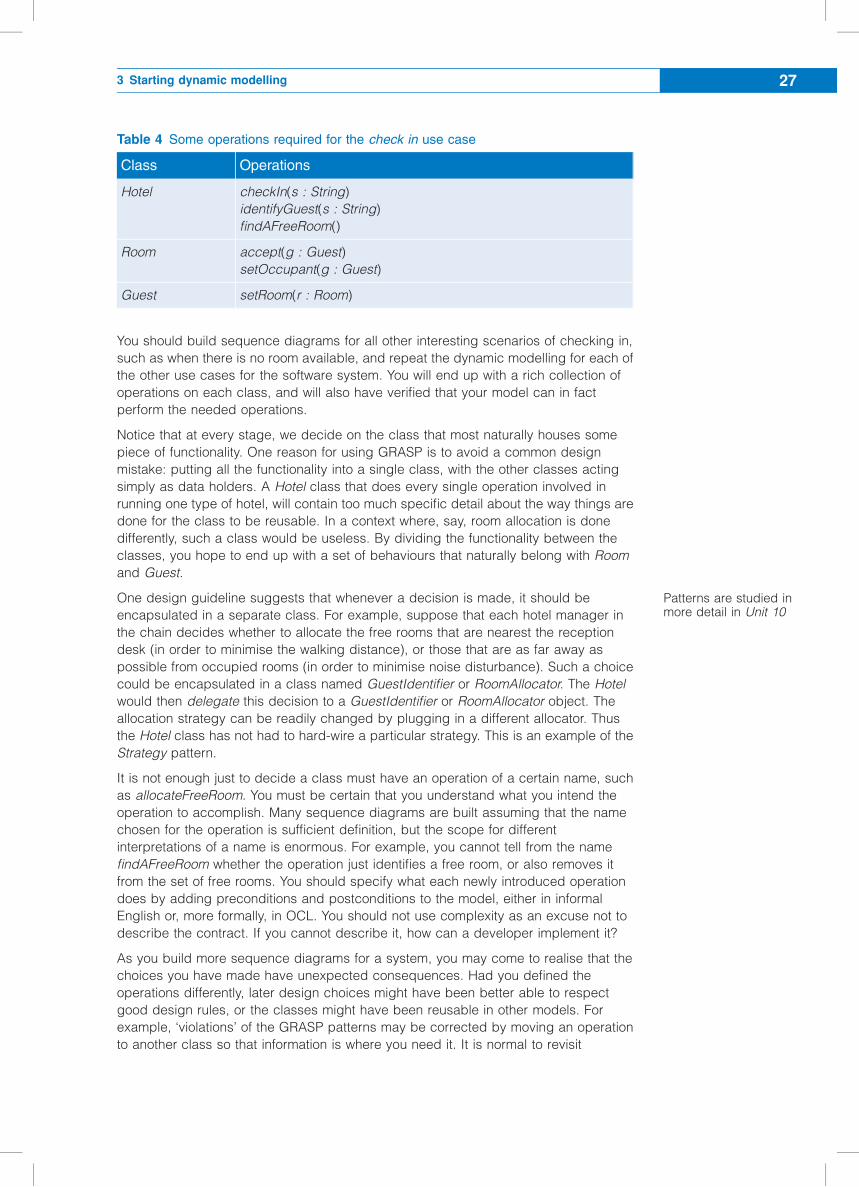
Table 4 Some operations required for the check in use case
Class Operations
Hotel checkIn(s : String)
identifyGuest(s : String)
findAFreeRoom()
Room accept(g : Guest)
setOccupant(g : Guest)
Guest setRoom(r : Room)
You should build sequence diagrams for all other interesting scenarios of checking in,
such as when there is no room available, and repeat the dynamic modelling for each of
the other use cases for the software system. You will end up with a rich collection of
operations on each class, and will also have verified that your model can in fact
perform the needed operations.
Notice that at every stage, we decide on the class that most naturally houses some
piece of functionality. One reason for using GRASP is to avoid a common design
mistake: putting all the functionality into a single class, with the other classes acting
simply as data holders. A Hotel class that does every single operation involved in
running one type of hotel, will contain too much specific detail about the way things are
done for the class to be reusable. In a context where, say, room allocation is done
differently, such a class would be useless. By dividing the functionality between the
classes, you hope to end up with a set of behaviours that naturally belong with Room
and Guest.
One design guideline suggests that whenever a decision is made, it should be
encapsulated in a separate class. For example, suppose that each hotel manager in
the chain decides whether to allocate the free rooms that are nearest the reception
desk (in order to minimise the walking distance), or those that are as far away as
possible from occupied rooms (in order to minimise noise disturbance). Such a choice
could be encapsulated in a class named GuestIdentifier or RoomAllocator. The Hotel
would then delegate this decision to a GuestIdentifier or RoomAllocator object. The
allocation strategy can be readily changed by plugging in a different allocator. Thus
the Hotel class has not had to hard-wire a particular strategy. This is an example of the
Strategy pattern.
It is not enough just to decide a class must have an operation of a certain name, such
as allocateFreeRoom. You must be certain that you understand what you intend the
operation to accomplish. Many sequence diagrams are built assuming that the name
chosen for the operation is sufficient definition, but the scope for different
interpretations of a name is enormous. For example, you cannot tell from the name
findAFreeRoom whether the operation just identifies a free room, or also removes it
from the set of free rooms. You should specify what each newly introduced operation
does by adding preconditions and postconditions to the model, either in informal
English or, more formally, in OCL. You should not use complexity as an excuse not to
describe the contract. If you cannot describe it, how can a developer implement it?
As you build more sequence diagrams for a system, you may come to realise that the
choices you have made have unexpected consequences. Had you defined the
operations differently, later design choices might have been better able to respect
good design rules, or the classes might have been reusable in other models. For
example, ‘violations’ of the GRASP patterns may be corrected by moving an operation
to another class so that information is where you need it. It is normal to revisit
Patterns are studied inmore detail in Unit 10
3 Starting dynamic modelling 27
completed diagrams to redesign them, in order to make the entire set cleaner and
more consistent.
During the construction of a sequence diagram, you will frequently find weaknesses in
the class model. For instance, in building a sequence diagram for printing a guest’s
bill, you may realise that you need to know what type of room the guest had occupied.
As we have not modelled room types, we would have to return to the class model and
decide how to represent room types before continuing with the sequence diagram.
Object-oriented design is very much an iterative process, alternating between
improving the structural model and deciding on the dynamic behaviour.
You may also discover classes that make implementation easier and more flexible, but
are not part of the specification model. For instance, we noticed earlier that inventing a
RoomAllocator class might give a more flexible hotel system. It is during the creation of
sequence diagrams that many new implementation classes are invented. They must be
added to the implementation class model, which slowly grows to contain considerably
more classes than the specification class model.
Note that there is a potential problem with the design in Figure 7. The checkIn method
has a String argument to identify a particular reservation, which is used to identify the
Guest object (see Figure 6). Although for simplicity we have had the user interface
pass in an external identifier, in practice a preferred approach would be for the user
interface to obtain a collection of the Reservation objects involved, then display the
collection and have the user pick the right one from the list. The message from the user
interface would then have an argument that is the object identifier of the actual
business object concerned, rather than just a string identifier. Of course, having a
Reservation object to pass in raises the question of where that object is created and
how the user interface found the object. The simple answer is ‘somewhere else in the
system’ – recall that here we are dealing with designing only part of the system, and
we do not expect it to solve all the issues that arise. This kind of situation is explored
further in Section 3 of Unit 7.
SAQ 9
(a) What does it mean to delegate in the context of object-oriented design?
(b) Would you describe a sequence diagram as a programming notation?
ANSWER...............................................................................................................
(a) One object is said to delegate behaviour to another when instead of implementing
some behaviour, it sends a message to another object that implements that
behaviour. We considered the possibility that instead of the Hotel doing all the work
of finding a free room and housing jill in it, the Hotel might delegate the work to a
Room by passing it the message attemptToAccommodate(jill).
(b) Not really, because all it shows is the inter-object message traffic. It does not
represent the algorithms needed by senders in order to decide when and to which
objects messages should be sent, or those needed by receivers in order to act on
the messages. When you have finished drawing sequence diagrams, you know the
interfaces of the various classes, but not how those interfaces will be implemented.
Unit 6 Interactions28
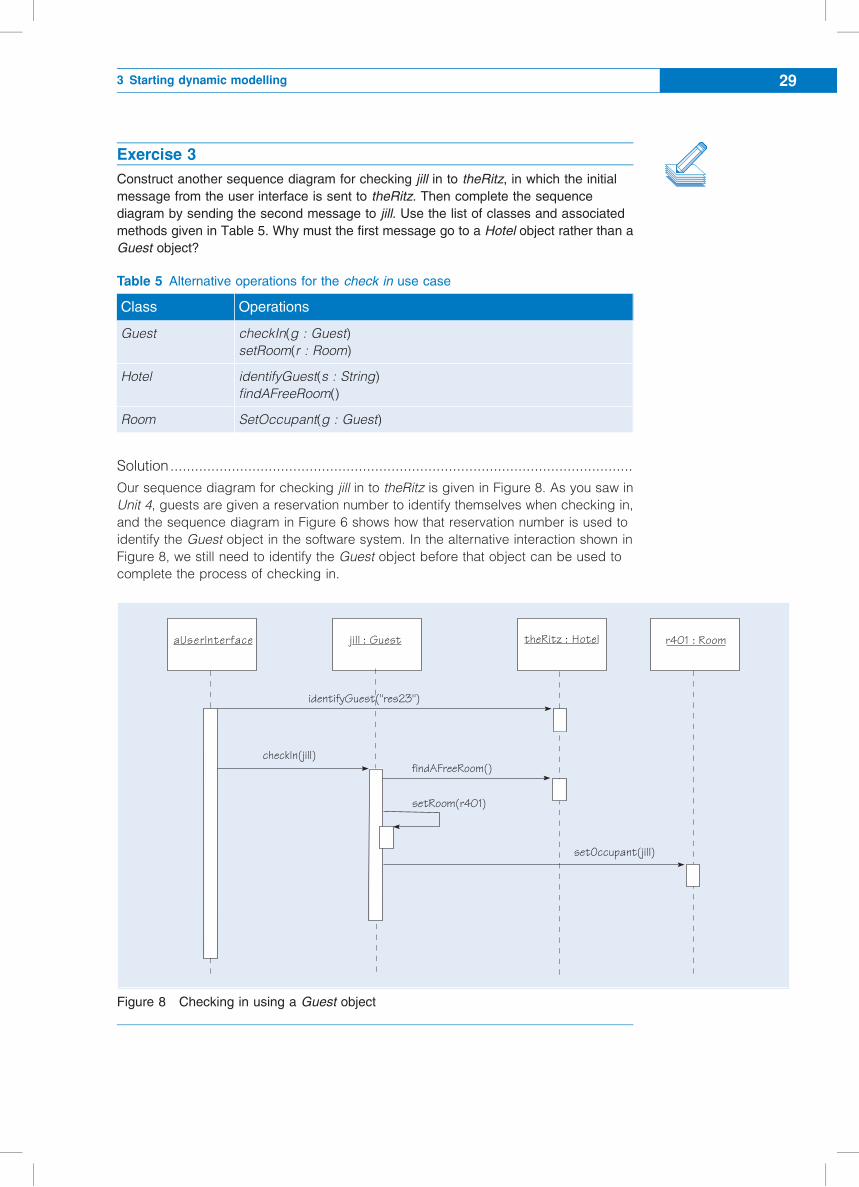
Exercise 3
Construct another sequence diagram for checking jill in to theRitz, in which the initial
message from the user interface is sent to theRitz. Then complete the sequence
diagram by sending the second message to jill. Use the list of classes and associated
methods given in Table 5. Why must the first message go to a Hotel object rather than a
Guest object?
Table 5 Alternative operations for the check in use case
Class Operations
Guest checkIn(g : Guest)
setRoom(r : Room)
Hotel identifyGuest(s : String)
findAFreeRoom()
Room SetOccupant(g : Guest)
Solution.................................................................................................................
Our sequence diagram for checking jill in to theRitz is given in Figure 8. As you saw in
Unit 4, guests are given a reservation number to identify themselves when checking in,
and the sequence diagram in Figure 6 shows how that reservation number is used to
identify the Guest object in the software system. In the alternative interaction shown in
Figure 8, we still need to identify the Guest object before that object can be used to
complete the process of checking in.
Figure 8 Checking in using a Guest object
theRitz : Hotel r401 : Roomjill : Guest
checkIn(jill)
aUserInterface
findAFreeRoom()
setOccupant(jill)
setRoom(r401)
identifyGuest("res23")
3 Starting dynamic modelling 29
Exercise 4
Imagine constructing some sequence diagrams for checking out a guest. What new
classes might suggest themselves as candidates for inclusion in the class model?
Solution.................................................................................................................
Checking out requires the completion of a Bill, which might contain a number of
separate items. A bill relates to the length of the stay, which has not been modelled.
Perhaps we need attributes to record arrival and departure. These might fit most
naturally in a Stay class. Payments may or may not be settled immediately, so it is wise
to separate a Bill from any Payment that might arise. Collected instances of Bill and
Payment might be naturally grouped into instances of an Account class.
All the above are extra classes that might have arisen when developing the use cases,
but might arise later in the design process. Classes that are inherently design classes,
which could not arise from writing use cases, might include a CheckerOut class to
encapsulate the procedures for checking out, or a RoomAllocator to centralise
decisions on how the set of free rooms is to be handled.
Exercise 5
The sequence diagram in Figure 6 shows the user interface sending a message checkIn
("res23") to theRitz. How might the user interface discover that this is the correct hotel to
send the message to?
Solution.................................................................................................................
This would be handled in another use case, probably log on, shown in Figures 18 and
19 of Unit 3. (This is the use case performed by the receptionist on start-up, in which
they identify the hotel that they are serving.)
This illustrates that though you may think of issues when developing a particular use
case, those issues may be properly resolved in other use cases.
3.6 Summary of section
Sequence diagrams are one kind of interaction diagram. They are used when you
move from a specification to a design as a way of helping you decide which parts of
the overall system behaviour should be allocated to which classes. So far, we have
used sequence diagrams only for specific scenarios of use cases – jill checking in to
theRitz, rather than aGuest checking in to aHotel.
Unit 6 Interactions30
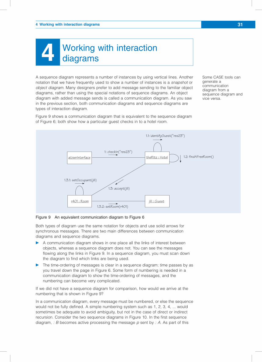
4 Working with interactiondiagrams
A sequence diagram represents a number of instances by using vertical lines. Another
notation that we have frequently used to show a number of instances is a snapshot or
object diagram. Many designers prefer to add message sending to the familiar object
diagrams, rather than using the special notations of sequence diagrams. An object
diagram with added message sends is called a communication diagram. As you saw
in the previous section, both communication diagrams and sequence diagrams are
types of interaction diagram.
Figure 9 shows a communication diagram that is equivalent to the sequence diagram
of Figure 6; both show how a particular guest checks in to a hotel room.
Figure 9 An equivalent communication diagram to Figure 6
Both types of diagram use the same notation for objects and use solid arrows for
synchronous messages. There are two main differences between communication
diagrams and sequence diagrams.
c A communication diagram shows in one place all the links of interest between
objects, whereas a sequence diagram does not. You can see the messages
flowing along the links in Figure 9. In a sequence diagram, you must scan down
the diagram to find which links are being used.
c The time-ordering of messages is clear in a sequence diagram; time passes by as
you travel down the page in Figure 6. Some form of numbering is needed in a
communication diagram to show the time-ordering of messages, and the
numbering can become very complicated.
If we did not have a sequence diagram for comparison, how would we arrive at the
numbering that is shown in Figure 9?
In a communication diagram, every message must be numbered, or else the sequence
would not be fully defined. A simple numbering system such as 1, 2, 3, 4, ... would
sometimes be adequate to avoid ambiguity, but not in the case of direct or indirect
recursion. Consider the two sequence diagrams in Figure 10. In the first sequence
diagram, : B becomes active processing the message p sent by : A. As part of this
aUserInterface theRitz : Hotel
r401 : Room jill : Guest
1: checkIn("res23")
1.3.2: setRoom(r401)
1.3: accept(jill)
1.3.1: setOccupant(jill)
1.2: findAFreeRoom()
1.1: identifyGuest("res23")
Some CASE tools cangenerate acommunicationdiagram from asequence diagram andvice versa.
4 Working with interaction diagrams 31
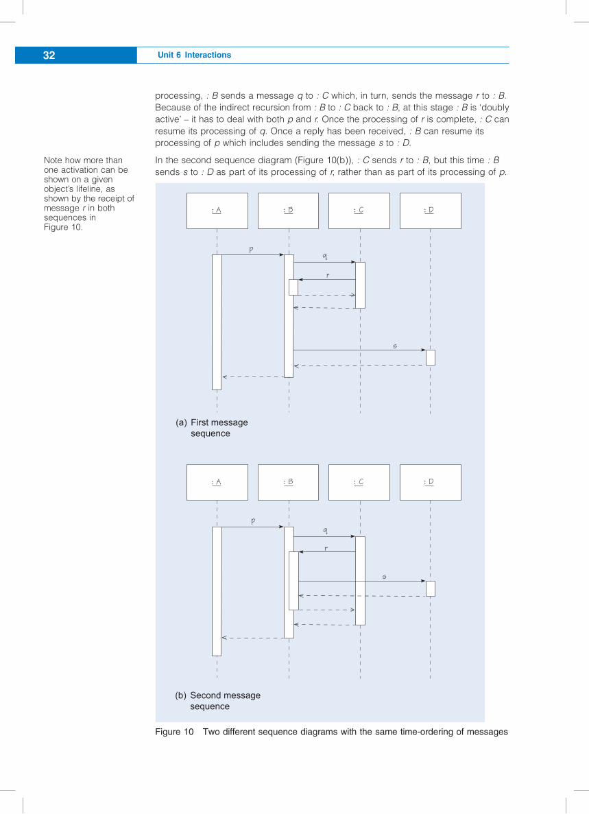
processing, : B sends a message q to : C which, in turn, sends the message r to : B.
Because of the indirect recursion from : B to : C back to : B, at this stage : B is ‘doubly
active’ – it has to deal with both p and r. Once the processing of r is complete, : C can
resume its processing of q. Once a reply has been received, : B can resume its
processing of p which includes sending the message s to : D.
In the second sequence diagram (Figure 10(b)), : C sends r to : B, but this time : B
sends s to : D as part of its processing of r, rather than as part of its processing of p.
Figure 10 Two different sequence diagrams with the same time-ordering of messages
: A : B : C : D
pq
r
s
D*456 .&55a(&5&37&0c&
: A : B : C : D
pq
r
s
R&c10% .&55a(&5&37&0c&
#a$
#b$
Note how more thanone activation can beshown on a givenobject’s lifeline, asshown by the receipt ofmessage r in bothsequences inFigure 10.
Unit 6 Interactions32
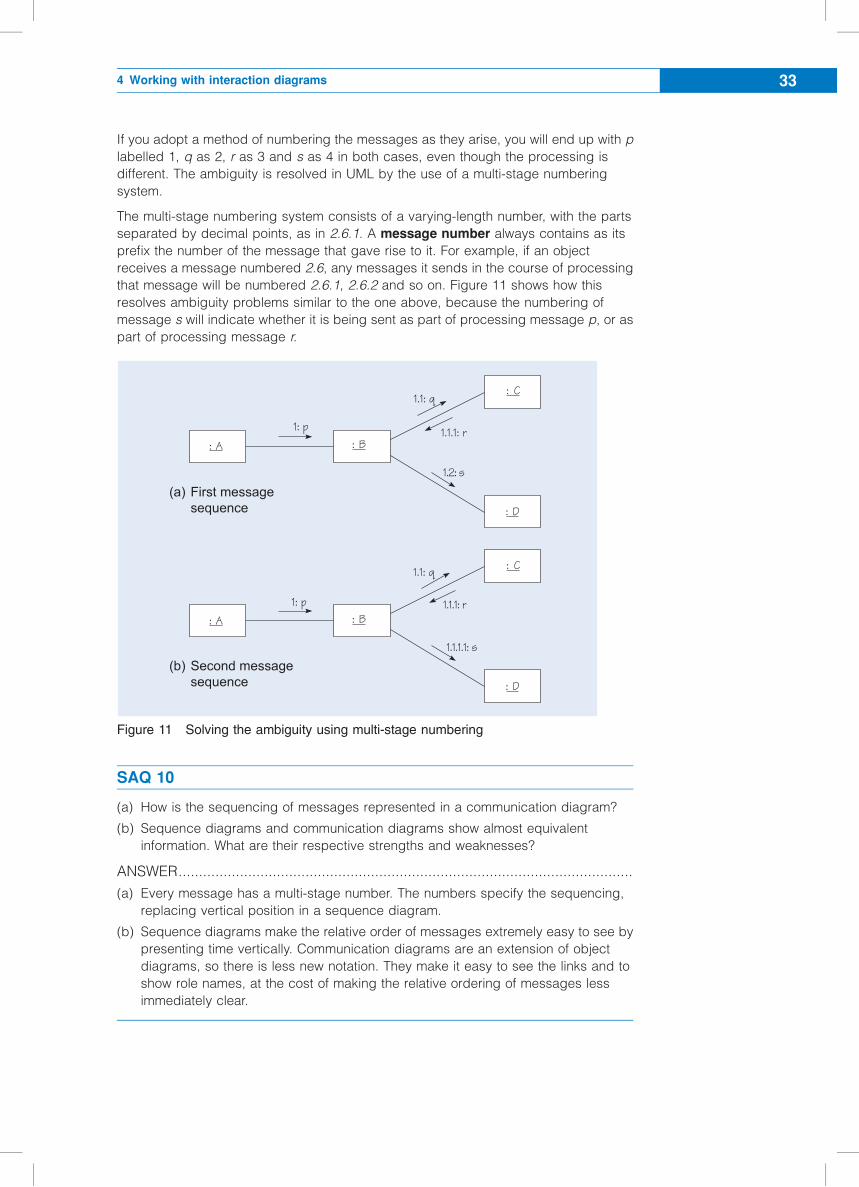
If you adopt a method of numbering the messages as they arise, you will end up with p
labelled 1, q as 2, r as 3 and s as 4 in both cases, even though the processing is
different. The ambiguity is resolved in UML by the use of a multi-stage numbering
system.
The multi-stage numbering system consists of a varying-length number, with the parts
separated by decimal points, as in 2.6.1. A message number always contains as its
prefix the number of the message that gave rise to it. For example, if an object
receives a message numbered 2.6, any messages it sends in the course of processing
that message will be numbered 2.6.1, 2.6.2 and so on. Figure 11 shows how this
resolves ambiguity problems similar to the one above, because the numbering of
message s will indicate whether it is being sent as part of processing message p, or as
part of processing message r.
Figure 11 Solving the ambiguity using multi-stage numbering
SAQ 10
(a) How is the sequencing of messages represented in a communication diagram?
(b) Sequence diagrams and communication diagrams show almost equivalent
information. What are their respective strengths and weaknesses?
ANSWER...............................................................................................................
(a) Every message has a multi-stage number. The numbers specify the sequencing,
replacing vertical position in a sequence diagram.
(b) Sequence diagrams make the relative order of messages extremely easy to see by
presenting time vertically. Communication diagrams are an extension of object
diagrams, so there is less new notation. They make it easy to see the links and to
show role names, at the cost of making the relative ordering of messages less
immediately clear.
1: p
1.1: q
1.1.1: r
1.2: s
D*456 .&55a(&5&37&0c&
1: p
1.1: q
1.1.1: r
1.1.1.1: s
R&c10% .&55a(&5&37&0c&
: A : B
: C
: D
#a$
#b$
: C
: D
: B: A
4 Working with interaction diagrams 33
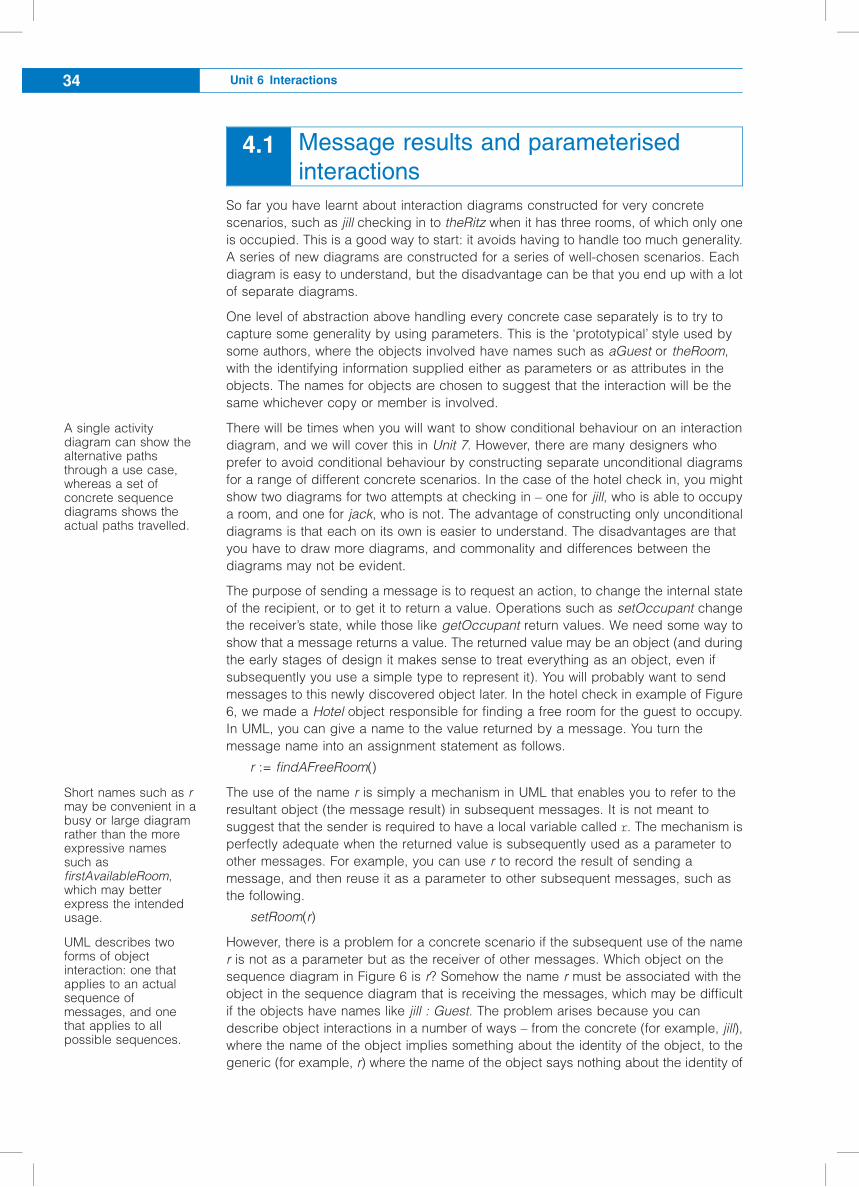
4.1 Message results and parameterised
interactions
So far you have learnt about interaction diagrams constructed for very concrete
scenarios, such as jill checking in to theRitz when it has three rooms, of which only one
is occupied. This is a good way to start: it avoids having to handle too much generality.
A series of new diagrams are constructed for a series of well-chosen scenarios. Each
diagram is easy to understand, but the disadvantage can be that you end up with a lot
of separate diagrams.
One level of abstraction above handling every concrete case separately is to try to
capture some generality by using parameters. This is the ‘prototypical’ style used by
some authors, where the objects involved have names such as aGuest or theRoom,
with the identifying information supplied either as parameters or as attributes in the
objects. The names for objects are chosen to suggest that the interaction will be the
same whichever copy or member is involved.
There will be times when you will want to show conditional behaviour on an interaction
diagram, and we will cover this in Unit 7. However, there are many designers who
prefer to avoid conditional behaviour by constructing separate unconditional diagrams
for a range of different concrete scenarios. In the case of the hotel check in, you might
show two diagrams for two attempts at checking in – one for jill, who is able to occupy
a room, and one for jack, who is not. The advantage of constructing only unconditional
diagrams is that each on its own is easier to understand. The disadvantages are that
you have to draw more diagrams, and commonality and differences between the
diagrams may not be evident.
The purpose of sending a message is to request an action, to change the internal state
of the recipient, or to get it to return a value. Operations such as setOccupant change
the receiver’s state, while those like getOccupant return values. We need some way to
show that a message returns a value. The returned value may be an object (and during
the early stages of design it makes sense to treat everything as an object, even if
subsequently you use a simple type to represent it). You will probably want to send
messages to this newly discovered object later. In the hotel check in example of Figure
6, we made a Hotel object responsible for finding a free room for the guest to occupy.
In UML, you can give a name to the value returned by a message. You turn the
message name into an assignment statement as follows.
r := findAFreeRoom()
The use of the name r is simply a mechanism in UML that enables you to refer to the
resultant object (the message result) in subsequent messages. It is not meant to
suggest that the sender is required to have a local variable called r. The mechanism is
perfectly adequate when the returned value is subsequently used as a parameter to
other messages. For example, you can use r to record the result of sending a
message, and then reuse it as a parameter to other subsequent messages, such as
the following.
setRoom(r)
However, there is a problem for a concrete scenario if the subsequent use of the name
r is not as a parameter but as the receiver of other messages. Which object on the
sequence diagram in Figure 6 is r? Somehow the name r must be associated with the
object in the sequence diagram that is receiving the messages, which may be difficult
if the objects have names like jill : Guest. The problem arises because you can
describe object interactions in a number of ways – from the concrete (for example, jill),
where the name of the object implies something about the identity of the object, to the
generic (for example, r) where the name of the object says nothing about the identity of
A single activitydiagram can show thealternative pathsthrough a use case,whereas a set ofconcrete sequencediagrams shows theactual paths travelled.
Short names such as rmay be convenient in abusy or large diagramrather than the moreexpressive namessuch asfirstAvailableRoom,which may betterexpress the intendedusage.
UML describes twoforms of objectinteraction: one thatapplies to an actualsequence ofmessages, and onethat applies to allpossible sequences.
Unit 6 Interactions34
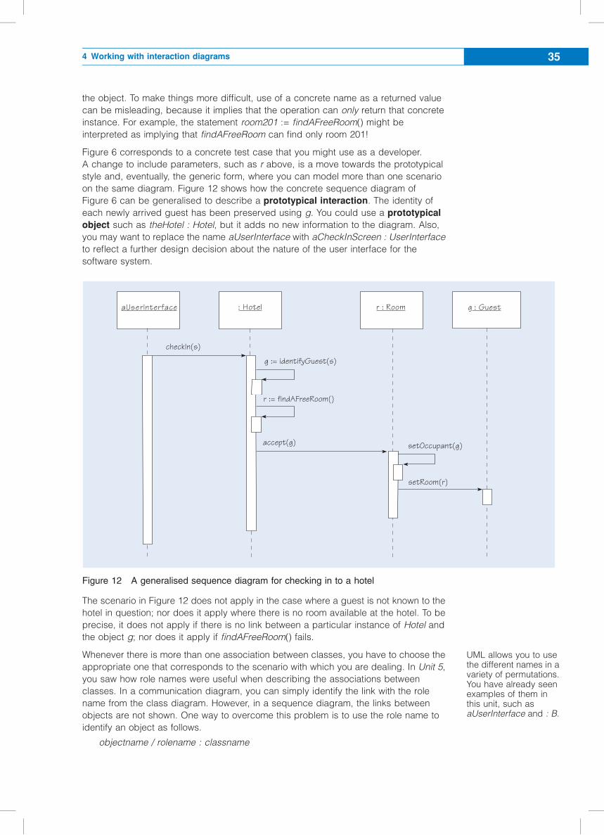
the object. To make things more difficult, use of a concrete name as a returned value
can be misleading, because it implies that the operation can only return that concrete
instance. For example, the statement room201 := findAFreeRoom() might be
interpreted as implying that findAFreeRoom can find only room 201!
Figure 6 corresponds to a concrete test case that you might use as a developer.
A change to include parameters, such as r above, is a move towards the prototypical
style and, eventually, the generic form, where you can model more than one scenario
on the same diagram. Figure 12 shows how the concrete sequence diagram of
Figure 6 can be generalised to describe a prototypical interaction. The identity of
each newly arrived guest has been preserved using g. You could use a prototypical
object such as theHotel : Hotel, but it adds no new information to the diagram. Also,
you may want to replace the name aUserInterface with aCheckInScreen : UserInterface
to reflect a further design decision about the nature of the user interface for the
software system.
Figure 12 A generalised sequence diagram for checking in to a hotel
The scenario in Figure 12 does not apply in the case where a guest is not known to the
hotel in question; nor does it apply where there is no room available at the hotel. To be
precise, it does not apply if there is no link between a particular instance of Hotel and
the object g; nor does it apply if findAFreeRoom() fails.
Whenever there is more than one association between classes, you have to choose the
appropriate one that corresponds to the scenario with which you are dealing. In Unit 5,
you saw how role names were useful when describing the associations between
classes. In a communication diagram, you can simply identify the link with the role
name from the class diagram. However, in a sequence diagram, the links between
objects are not shown. One way to overcome this problem is to use the role name to
identify an object as follows.
objectname / rolename : classname
checkIn(s)
aUserInterface
r := findAFreeRoom()
accept(g) setOccupant(g)
setRoom(r)
: Hotel r : Room g : Guest
g := identifyGuest(s)
UML allows you to usethe different names in avariety of permutations.You have already seenexamples of them inthis unit, such asaUserInterface and : B.
4 Working with interaction diagrams 35
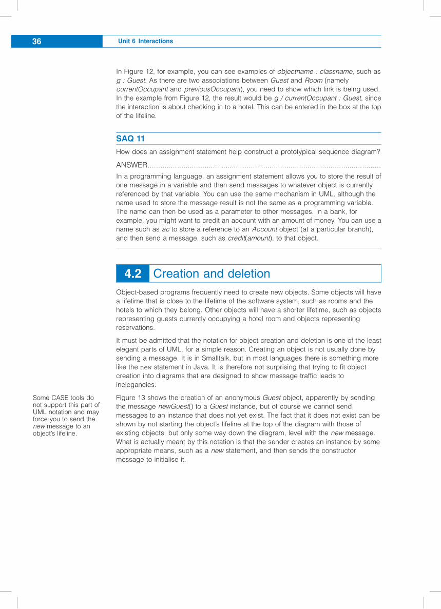
In Figure 12, for example, you can see examples of objectname : classname, such as
g : Guest. As there are two associations between Guest and Room (namely
currentOccupant and previousOccupant), you need to show which link is being used.
In the example from Figure 12, the result would be g / currentOccupant : Guest, since
the interaction is about checking in to a hotel. This can be entered in the box at the top
of the lifeline.
SAQ 11
How does an assignment statement help construct a prototypical sequence diagram?
ANSWER...............................................................................................................
In a programming language, an assignment statement allows you to store the result of
one message in a variable and then send messages to whatever object is currently
referenced by that variable. You can use the same mechanism in UML, although the
name used to store the message result is not the same as a programming variable.
The name can then be used as a parameter to other messages. In a bank, for
example, you might want to credit an account with an amount of money. You can use a
name such as ac to store a reference to an Account object (at a particular branch),
and then send a message, such as credit(amount), to that object.
4.2 Creation and deletion
Object-based programs frequently need to create new objects. Some objects will have
a lifetime that is close to the lifetime of the software system, such as rooms and the
hotels to which they belong. Other objects will have a shorter lifetime, such as objects
representing guests currently occupying a hotel room and objects representing
reservations.
It must be admitted that the notation for object creation and deletion is one of the least
elegant parts of UML, for a simple reason. Creating an object is not usually done by
sending a message. It is in Smalltalk, but in most languages there is something more
like the new statement in Java. It is therefore not surprising that trying to fit object
creation into diagrams that are designed to show message traffic leads to
inelegancies.
Figure 13 shows the creation of an anonymous Guest object, apparently by sending
the message newGuest() to a Guest instance, but of course we cannot send
messages to an instance that does not yet exist. The fact that it does not exist can be
shown by not starting the object’s lifeline at the top of the diagram with those of
existing objects, but only some way down the diagram, level with the new message.
What is actually meant by this notation is that the sender creates an instance by some
appropriate means, such as a new statement, and then sends the constructor
message to initialise it.
Some CASE tools donot support this part ofUML notation and mayforce you to send thenew message to anobject’s lifeline.
Unit 6 Interactions36
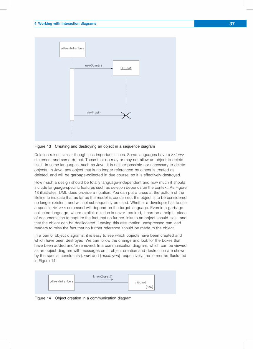
Figure 13 Creating and destroying an object in a sequence diagram
Deletion raises similar though less important issues. Some languages have a delete
statement and some do not. Those that do may or may not allow an object to delete
itself. In some languages, such as Java, it is neither possible nor necessary to delete
objects. In Java, any object that is no longer referenced by others is treated as
deleted, and will be garbage-collected in due course, so it is effectively destroyed.
How much a design should be totally language-independent and how much it should
include language-specific features such as deletion depends on the context. As Figure
13 illustrates, UML does provide a notation. You can put a cross at the bottom of the
lifeline to indicate that as far as the model is concerned, the object is to be considered
no longer existent, and will not subsequently be used. Whether a developer has to use
a specific delete command will depend on the target language. Even in a garbage-
collected language, where explicit deletion is never required, it can be a helpful piece
of documentation to capture the fact that no further links to an object should exist, and
that the object can be deallocated. Leaving this assumption unexpressed can lead
readers to miss the fact that no further reference should be made to the object.
In a pair of object diagrams, it is easy to see which objects have been created and
which have been destroyed. We can follow the change and look for the boxes that
have been added and/or removed. In a communication diagram, which can be viewed
as an object diagram with messages on it, object creation and destruction are shown
by the special constraints {new} and {destroyed} respectively, the former as illustrated
in Figure 14.
Figure 14 Object creation in a communication diagram
: GuestnewGuest()
destroy()
aUserInterface
: GuestaUserInterface1: newGuest()
{new}
4 Working with interaction diagrams 37
If you want to show an object’s complete life cycle in one interaction, you can use the
{transient} constraint. Otherwise you should treat creation and destruction as two
separate interactions and show them on two separate communication diagrams. You
can use the same notation for links. For example, if an interaction creates a new link
between two objects, use the {new} constraint on the communication diagram.
SAQ 12
Figure 14 shows UML notation for creating new Guest objects in a communication
diagram. Has this cured the problem of apparently sending messages to objects that
do not yet exist?
ANSWER...............................................................................................................
No – it is still a notation based on message sending. As Figure 14 shows, marking the
instance {new} has not captured exactly when it comes into existence. We are still
dependent on the pseudo-message newGuest() to express creation.
4.3 Levels of detail
At every stage of a design, you have to decide either to specify what is required in just
enough detail for a programmer who understands the domain, or to spell out in detail
how some goal is to be achieved. For example, the hotel check in scenario led to a
requirement for an operation called findAFreeRoom, which returned a Room object.
You could go into the precise details of how this might work, or you could simply
specify the necessary operation by defining a precondition and a postcondition, and
leave the coding to a programmer. There is no one correct level at which to stop
designing and start trusting programming professionals. A common mistake is to
include more details than are necessary, spelling out unimportant details. This has
been described as writing Java in pictures, and you can easily get details wrong or
introduce inconsistencies. If you really want to specify low-level details, Java is a
reasonable way to do it. Your job as a designer is to work at a higher level of
abstraction, capturing structural aspects that cannot easily be expressed in code.
Another reason for not adding further detail to an interaction diagram is to ensure that
the diagram does not get too big and, therefore, difficult to understand. You can
always stop at a given level of detail by showing the sending of a message but not
showing the implementation of the method in the receiver. Then, on a new diagram,
you can show how that operation is actually implemented. In effect, you are using an
interaction diagram to show how something as small as a single step in a scenario can
be achieved.
Software components allow the developer to perform repeatable tasks, which may be
as small as one step in a scenario, or as large as a use case (or bigger). If you treat
the component as a single class (or package), an interaction diagram can show how
an instance of that component should behave when other external objects send
messages to it.
SAQ 13
(a) How does a sequence diagram drawn for a use case scenario differ from one
drawn to show how an internal operation, such as findAFreeRoom in Figure 12, is
carried out?
Unit 6 Interactions38
(b) Other than the simple realisation of a use case scenario, what are the other uses of
interaction diagrams?
(c) Would you expect to use sequence diagrams in a conceptual model?
ANSWER...............................................................................................................
(a) A sequence diagram of a use case scenario will always have the very first
message originating from an object which has been stimulated, directly or
indirectly, by an actor (usually a user interface object). An internal operation will be
invoked by a message that has been identified in the use case scenario. You can
show how the recipient of that message achieves the required behaviour (how a
free room is found, for example). In all other respects they are the same.
(b) An interaction diagram can be drawn at any level of detail for a software system;
use cases are just one example. Other uses of interaction diagrams are as follows.
c They show how a class provides an operation. This is sometimes called a
subcommunication. An example might be documenting how findAFreeRoom
works in the hotel example of Figure 6, as this is just one operation on a class
rather than a particular use case scenario.
c They show how a component can be used. A component might need various
operations to be invoked in a particular sequence in order to achieve some
goal. An interaction diagram can document a typical interchange of messages.
c They show how a design pattern works. We described the possibility of a Hotel
delegating its room allocation to a RoomAllocator class, and mentioned that
this is a case of the Strategy pattern in which behaviour is moved out to a
separate object.
Alternatively, we could describe this pattern in general terms using a sequence
diagram. The instances would be general (prototypical) objects with names
such as theServer and theDelegate.
(c) Sequence diagrams are about message passing between software objects, and
conceptual models are about things in the world, where the language of message
passing makes no sense.
Exercise 6
Recall Exercise 3, where you were asked to model the checking in sequence. Using the
multi-stage numbering scheme, draw a communication diagram equivalent to the
sequence diagram in Figure 8.
Solution.................................................................................................................
Our solution is shown in Figure 15.
4 Working with interaction diagrams 39
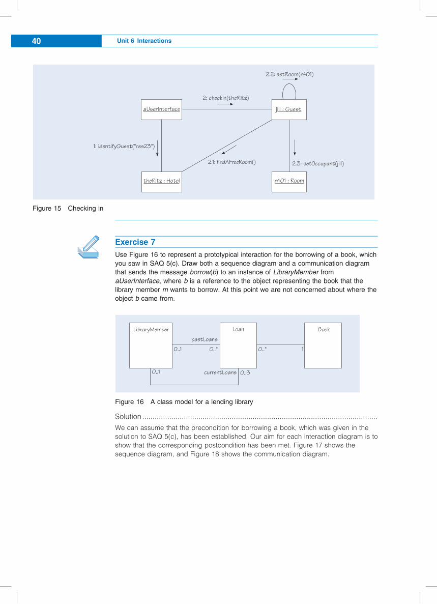
Figure 15 Checking in
Exercise 7
Use Figure 16 to represent a prototypical interaction for the borrowing of a book, which
you saw in SAQ 5(c). Draw both a sequence diagram and a communication diagram
that sends the message borrow(b) to an instance of LibraryMember from
aUserInterface, where b is a reference to the object representing the book that the
library member m wants to borrow. At this point we are not concerned about where the
object b came from.
Figure 16 A class model for a lending library
Solution.................................................................................................................
We can assume that the precondition for borrowing a book, which was given in the
solution to SAQ 5(c), has been established. Our aim for each interaction diagram is to
show that the corresponding postcondition has been met. Figure 17 shows the
sequence diagram, and Figure 18 shows the communication diagram.
2: checkIn(theRitz)
2.2: setRoom(r401)
2.1: findAFreeRoom() 2.3: setOccupant(jill)
aUserInterface
theRitz : Hotel r401 : Room
jill : Guest
1: identifyGuest("res23")
10..*
LibraryMember
pastLoans
currentLoans
Loan Book
0..3
0..1 0..*
0..1
Unit 6 Interactions40
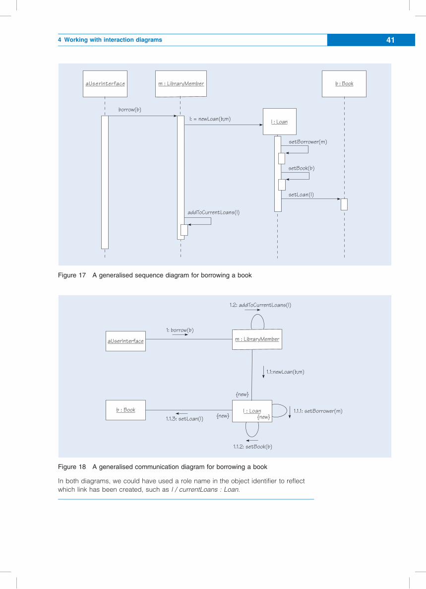
Figure 17 A generalised sequence diagram for borrowing a book
Figure 18 A generalised communication diagram for borrowing a book
In both diagrams, we could have used a role name in the object identifier to reflect
which link has been created, such as l / currentLoans : Loan.
borrow(b)
aUserInterface
setBook(b)
addToCurrentLoans(l)
setBorrower(m)
setLoan(l)
b : Book
l: = newLoan(b,m)
m : LibraryMember
l : Loan
l : Loan
aUserInterface m : LibraryMember
b : Book{new}
1: borrow(b)
1.1.3: setLoan(l)1.1.1: setBorrower(m)
1.1.2: setBook(b)
1.1:newLoan(b,m)
1.2: addToCurrentLoans(l)
{new}
{new}
4 Working with interaction diagrams 41
4.4 Summary of section
This section has introduced communication diagrams as a different kind of interaction
diagram to deal with the dynamic behaviour of a software system, and you have seen
examples of how to add detail to your interaction diagrams as follows.
c Communication diagrams provide an alternative notation to sequence diagrams,
emphasising message routes rather than timing.
c Communication diagrams require a complex numbering system in order to make
the actual sequencing of messages clear.
c Sequence diagrams can be enriched by notation to assign the result of a message
to a local variable.
c Sequence and communication diagrams have different notations relating to the
creation and deletion of objects.
c Sequence and communication diagrams can be drawn at any level of detail for a
software system. They can show how a use case is turned into object interactions,
how a class provides an operation, how a component can be used, and how a
design pattern works.
Sequence diagrams can be drawn at many different levels of detail, ranging from
concrete scenarios about individual objects to general ones operating on prototypical
objects such as theMember.
Unit 6 Interactions42
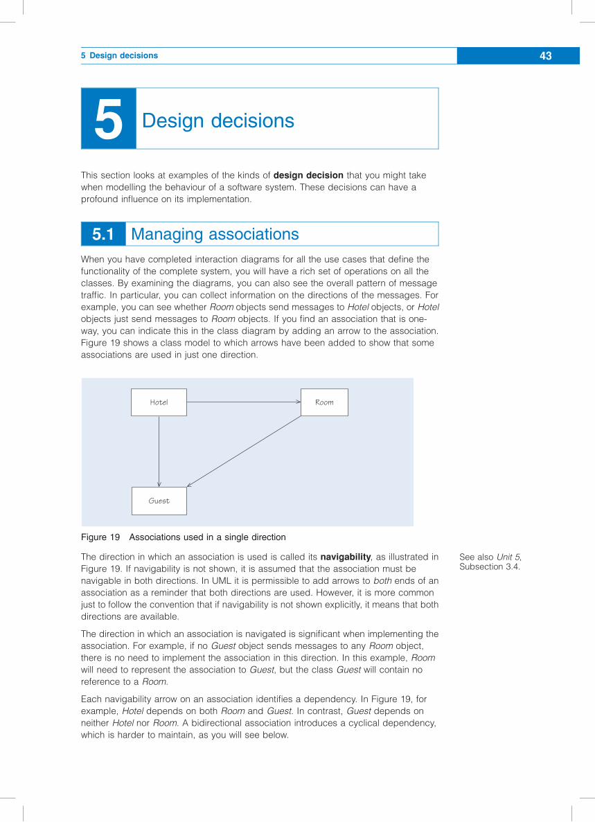
5 Design decisions
This section looks at examples of the kinds of design decision that you might take
when modelling the behaviour of a software system. These decisions can have a
profound influence on its implementation.
5.1 Managing associations
When you have completed interaction diagrams for all the use cases that define the
functionality of the complete system, you will have a rich set of operations on all the
classes. By examining the diagrams, you can also see the overall pattern of message
traffic. In particular, you can collect information on the directions of the messages. For
example, you can see whether Room objects send messages to Hotel objects, or Hotel
objects just send messages to Room objects. If you find an association that is one-
way, you can indicate this in the class diagram by adding an arrow to the association.
Figure 19 shows a class model to which arrows have been added to show that some
associations are used in just one direction.
Figure 19 Associations used in a single direction
The direction in which an association is used is called its navigability, as illustrated in
Figure 19. If navigability is not shown, it is assumed that the association must be
navigable in both directions. In UML it is permissible to add arrows to both ends of an
association as a reminder that both directions are used. However, it is more common
just to follow the convention that if navigability is not shown explicitly, it means that both
directions are available.
The direction in which an association is navigated is significant when implementing the
association. For example, if no Guest object sends messages to any Room object,
there is no need to implement the association in this direction. In this example, Room
will need to represent the association to Guest, but the class Guest will contain no
reference to a Room.
Each navigability arrow on an association identifies a dependency. In Figure 19, for
example, Hotel depends on both Room and Guest. In contrast, Guest depends on
neither Hotel nor Room. A bidirectional association introduces a cyclical dependency,
which is harder to maintain, as you will see below.
Hotel Room
Guest
See also Unit 5,Subsection 3.4.
5 Design decisions 43
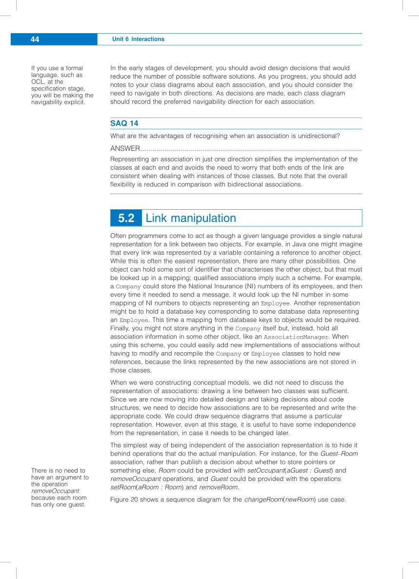
In the early stages of development, you should avoid design decisions that would
reduce the number of possible software solutions. As you progress, you should add
notes to your class diagrams about each association, and you should consider the
need to navigate in both directions. As decisions are made, each class diagram
should record the preferred navigability direction for each association.
SAQ 14
What are the advantages of recognising when an association is unidirectional?
ANSWER...............................................................................................................
Representing an association in just one direction simplifies the implementation of the
classes at each end and avoids the need to worry that both ends of the link are
consistent when dealing with instances of those classes. But note that the overall
flexibility is reduced in comparison with bidirectional associations.
5.2 Link manipulation
Often programmers come to act as though a given language provides a single natural
representation for a link between two objects. For example, in Java one might imagine
that every link was represented by a variable containing a reference to another object.
While this is often the easiest representation, there are many other possibilities. One
object can hold some sort of identifier that characterises the other object, but that must
be looked up in a mapping; qualified associations imply such a scheme. For example,
a Company could store the National Insurance (NI) numbers of its employees, and then
every time it needed to send a message, it would look up the NI number in some
mapping of NI numbers to objects representing an Employee. Another representation
might be to hold a database key corresponding to some database data representing
an Employee. This time a mapping from database keys to objects would be required.
Finally, you might not store anything in the Company itself but, instead, hold all
association information in some other object, like an AssociationManager. When
using this scheme, you could easily add new implementations of associations without
having to modify and recompile the Company or Employee classes to hold new
references, because the links represented by the new associations are not stored in
those classes.
When we were constructing conceptual models, we did not need to discuss the
representation of associations: drawing a line between two classes was sufficient.
Since we are now moving into detailed design and taking decisions about code
structures, we need to decide how associations are to be represented and write the
appropriate code. We could draw sequence diagrams that assume a particular
representation. However, even at this stage, it is useful to have some independence
from the representation, in case it needs to be changed later.
The simplest way of being independent of the association representation is to hide it
behind operations that do the actual manipulation. For instance, for the Guest–Room
association, rather than publish a decision about whether to store pointers or
something else, Room could be provided with setOccupant(aGuest : Guest) and
removeOccupant operations, and Guest could be provided with the operations
setRoom(aRoom : Room) and removeRoom.
Figure 20 shows a sequence diagram for the changeRoom(newRoom) use case.
If you use a formallanguage, such asOCL, at thespecification stage,you will be making thenavigability explicit.
There is no need tohave an argument tothe operationremoveOccupantbecause each roomhas only one guest.
Unit 6 Interactions44
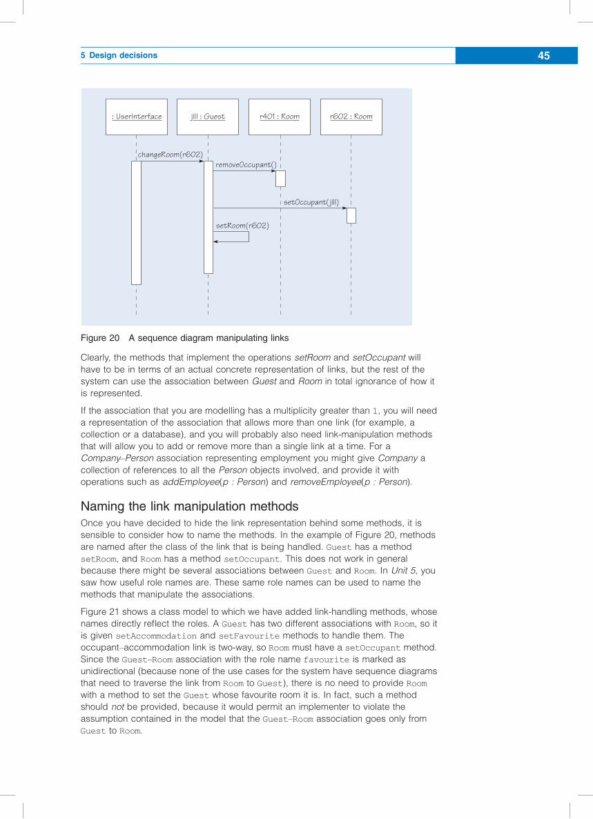
Figure 20 A sequence diagram manipulating links
Clearly, the methods that implement the operations setRoom and setOccupant will
have to be in terms of an actual concrete representation of links, but the rest of the
system can use the association between Guest and Room in total ignorance of how it
is represented.
If the association that you are modelling has a multiplicity greater than 1, you will need
a representation of the association that allows more than one link (for example, a
collection or a database), and you will probably also need link-manipulation methods
that will allow you to add or remove more than a single link at a time. For a
Company–Person association representing employment you might give Company a
collection of references to all the Person objects involved, and provide it with
operations such as addEmployee(p : Person) and removeEmployee(p : Person).
Naming the link manipulation methods
Once you have decided to hide the link representation behind some methods, it is
sensible to consider how to name the methods. In the example of Figure 20, methods
are named after the class of the link that is being handled. Guest has a method
setRoom, and Room has a method setOccupant. This does not work in general
because there might be several associations between Guest and Room. In Unit 5, you
saw how useful role names are. These same role names can be used to name the
methods that manipulate the associations.
Figure 21 shows a class model to which we have added link-handling methods, whose
names directly reflect the roles. A Guest has two different associations with Room, so it
is given setAccommodation and setFavourite methods to handle them. The
occupant–accommodation link is two-way, so Room must have a setOccupant method.
Since the Guest–Room association with the role name favourite is marked as
unidirectional (because none of the use cases for the system have sequence diagrams
that need to traverse the link from Room to Guest), there is no need to provide Room
with a method to set the Guest whose favourite room it is. In fact, such a method
should not be provided, because it would permit an implementer to violate the
assumption contained in the model that the Guest–Room association goes only from
Guest to Room.
: UserInterface jill : Guest r401 : Room r602 : Room
changeRoom(r602)removeOccupant()
setOccupant( jill)
setRoom(r602)
5 Design decisions 45
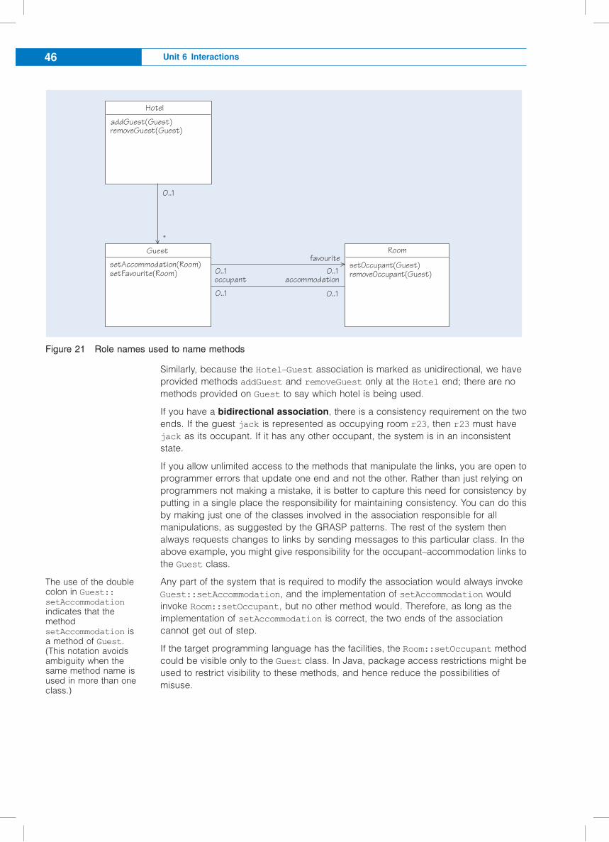
Figure 21 Role names used to name methods
Similarly, because the Hotel–Guest association is marked as unidirectional, we have
provided methods addGuest and removeGuest only at the Hotel end; there are no
methods provided on Guest to say which hotel is being used.
If you have a bidirectional association, there is a consistency requirement on the two
ends. If the guest jack is represented as occupying room r23, then r23 must have
jack as its occupant. If it has any other occupant, the system is in an inconsistent
state.
If you allow unlimited access to the methods that manipulate the links, you are open to
programmer errors that update one end and not the other. Rather than just relying on
programmers not making a mistake, it is better to capture this need for consistency by
putting in a single place the responsibility for maintaining consistency. You can do this
by making just one of the classes involved in the association responsible for all
manipulations, as suggested by the GRASP patterns. The rest of the system then
always requests changes to links by sending messages to this particular class. In the
above example, you might give responsibility for the occupant–accommodation links to
the Guest class.
Any part of the system that is required to modify the association would always invoke
Guest::setAccommodation, and the implementation of setAccommodation would
invoke Room::setOccupant, but no other method would. Therefore, as long as the
implementation of setAccommodation is correct, the two ends of the association
cannot get out of step.
If the target programming language has the facilities, the Room::setOccupant method
could be visible only to the Guest class. In Java, package access restrictions might be
used to restrict visibility to these methods, and hence reduce the possibilities of
misuse.
Hotel
addGuest(Guest)removeGuest(Guest)
Guest
setAccommodation(Room)setFavourite(Room)
0..1
occupant accommodation
0..1
favouriteRoom
*
0..1 0..1
0..1
setOccupant(Guest)removeOccupant(Guest)
The use of the doublecolon in Guest::setAccommodation
indicates that themethodsetAccommodation isa method of Guest.(This notation avoidsambiguity when thesame method name isused in more than oneclass.)
Unit 6 Interactions46
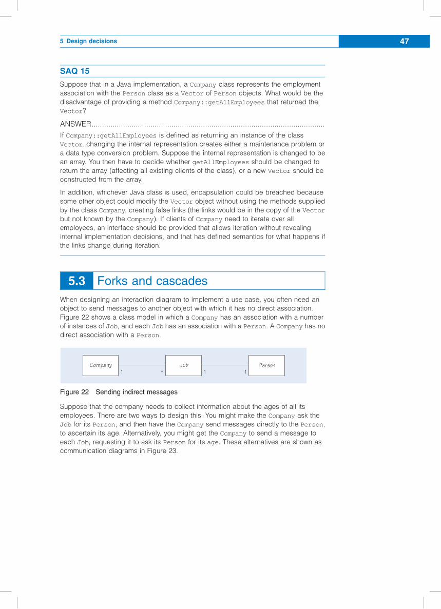
SAQ 15
Suppose that in a Java implementation, a Company class represents the employment
association with the Person class as a Vector of Person objects. What would be the
disadvantage of providing a method Company::getAllEmployees that returned the
Vector?
ANSWER...............................................................................................................
If Company::getAllEmployees is defined as returning an instance of the class
Vector, changing the internal representation creates either a maintenance problem or
a data type conversion problem. Suppose the internal representation is changed to be
an array. You then have to decide whether getAllEmployees should be changed to
return the array (affecting all existing clients of the class), or a new Vector should be
constructed from the array.
In addition, whichever Java class is used, encapsulation could be breached because
some other object could modify the Vector object without using the methods supplied
by the class Company, creating false links (the links would be in the copy of the Vector
but not known by the Company). If clients of Company need to iterate over all
employees, an interface should be provided that allows iteration without revealing
internal implementation decisions, and that has defined semantics for what happens if
the links change during iteration.
5.3 Forks and cascades
When designing an interaction diagram to implement a use case, you often need an
object to send messages to another object with which it has no direct association.
Figure 22 shows a class model in which a Company has an association with a number
of instances of Job, and each Job has an association with a Person. A Company has no
direct association with a Person.
Figure 22 Sending indirect messages
Suppose that the company needs to collect information about the ages of all its
employees. There are two ways to design this. You might make the Company ask the
Job for its Person, and then have the Company send messages directly to the Person,
to ascertain its age. Alternatively, you might get the Company to send a message to
each Job, requesting it to ask its Person for its age. These alternatives are shown as
communication diagrams in Figure 23.
1Company Job Person
* 11
5 Design decisions 47
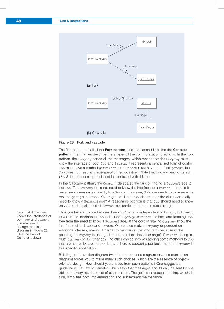
Figure 23 Fork and cascade
The first pattern is called the Fork pattern, and the second is called the Cascade
pattern. Their names describe the shapes of the communication diagrams. In the Fork
pattern, the Company sends all the messages, which means that the Company must
know the interface of both Job and Person. It represents a centralised form of control.
Job must have a method getPerson, and Person must have a method getAge, but
Job does not need any age-specific methods itself. Note that fork was encountered in
Unit 3, but that sense should not be confused with this one.
In the Cascade pattern, the Company delegates the task of finding a Person’s age to
the Job. The Company does not need to know the interface to a Person, because it
never sends messages directly to a Person. However, Job now needs to have an extra
method getAgeOfPerson. You might not like this decision: does the class Job really
need to know a Person’s age? A reasonable position is that Job should need to know
only about the existence of Person, not particular attributes such as age.
Thus you have a choice between keeping Company independent of Person, but having
to widen the interface to Job to include a getAgeOfPerson method, and keeping Job
free from the need to know a Person’s age, at the cost of making Company know the
interfaces of both Job and Person. One choice makes Company dependent on
additional classes, making it harder to maintain in the long term because of the
coupling. If Company is changed, must the other classes change? If Person changes,
must Company or Job change? The other choice involves adding some methods to Job
that are not really about a Job, but are there to support a particular need of Company in
this specific application.
Building an interaction diagram (whether a sequence diagram or a communication
diagram) forces you to make many such choices, which are the essence of object-
oriented design. How should you choose from such patterns? One suggested
guideline is the Law of Demeter, which says that messages should only be sent by one
object to a very restricted set of other objects. The goal is to reduce coupling, which, in
turn, simplifies both implementation and subsequent maintenance.
j3 : Job
IBM : Company
jane : Person
1: getPerson
2: getAge
(a) Fork
1.1: getAge
1: getAgeOfPerson
j3 : JobIBM : Company
jane : Person
(b) Cascade
Note that if Companyknows the interfaces ofboth Job and Person,you also need tochange the classdiagram in Figure 22.(See the Law ofDemeter below.)
Unit 6 Interactions48
The Law of Demeter states that a method m in a class A should not send a message to
another object unless that object is one of the following:
c an instance variable used in the method m;
c a parameter to the method m;
c an object created in the method m;
c a global variable (the nearest thing to this in Java is a public static variable) used
in the method m.
Note that an object should avoid invoking methods on another object returned by some
method, where the returned object does not qualify under one of the above situations.
There is nothing magical about the Law of Demeter. It is just guidance for avoiding
certain patterns of message sending that can lead to over-coupled and inflexible
systems. The fundamental idea is that an object only needs to know about its
immediate associated neighbours. What the neighbours know should remain private to
them. Instead, objects should confine themselves to asking their immediate
neighbours to do something for them, and should remain ignorant of their neighbours’
representation of further relationships. The cost of using the law is that you must
usually use the Cascade pattern rather than the Fork pattern. This means adding extra
methods to the intermediate classes, such as Job in Figure 22, in order to forward
requests down the chain.
SAQ 16
(a) According to the Law of Demeter, an object should only send messages to a
certain set of objects including the object itself. List the other objects.
(b) In Figure 23, which pattern would be outlawed by the Law of Demeter?
ANSWER...............................................................................................................
(a) The Law of Demeter allows an object to send messages to:
c any objects communicated as parameters of the current method;
c any new objects that the object has created in the current method;
c any objects to which the object has direct links – its neighbours;
c itself.
Note that the law does not allow sending messages to objects that are returned as
a result of sending other messages.
(b) The Fork pattern would be outlawed. Here, it would involve sending a message to
the Job to get a Person, and then sending messages to the resultant Person
object. The law bans the sending of messages to objects that are returned as a
result of sending other messages.
The Cascade implementation involves the Company talking only to Job, and Job
talking only to Person. Both of these are direct associations, so the Law of
Demeter will allow this. One advantage of using the Cascade pattern is that the
Company is independent of how the age of an employee is represented. You could
store the age directly within Job, or you could store it in an associated Person
object. The Company will be oblivious to such choices.
5 Design decisions 49
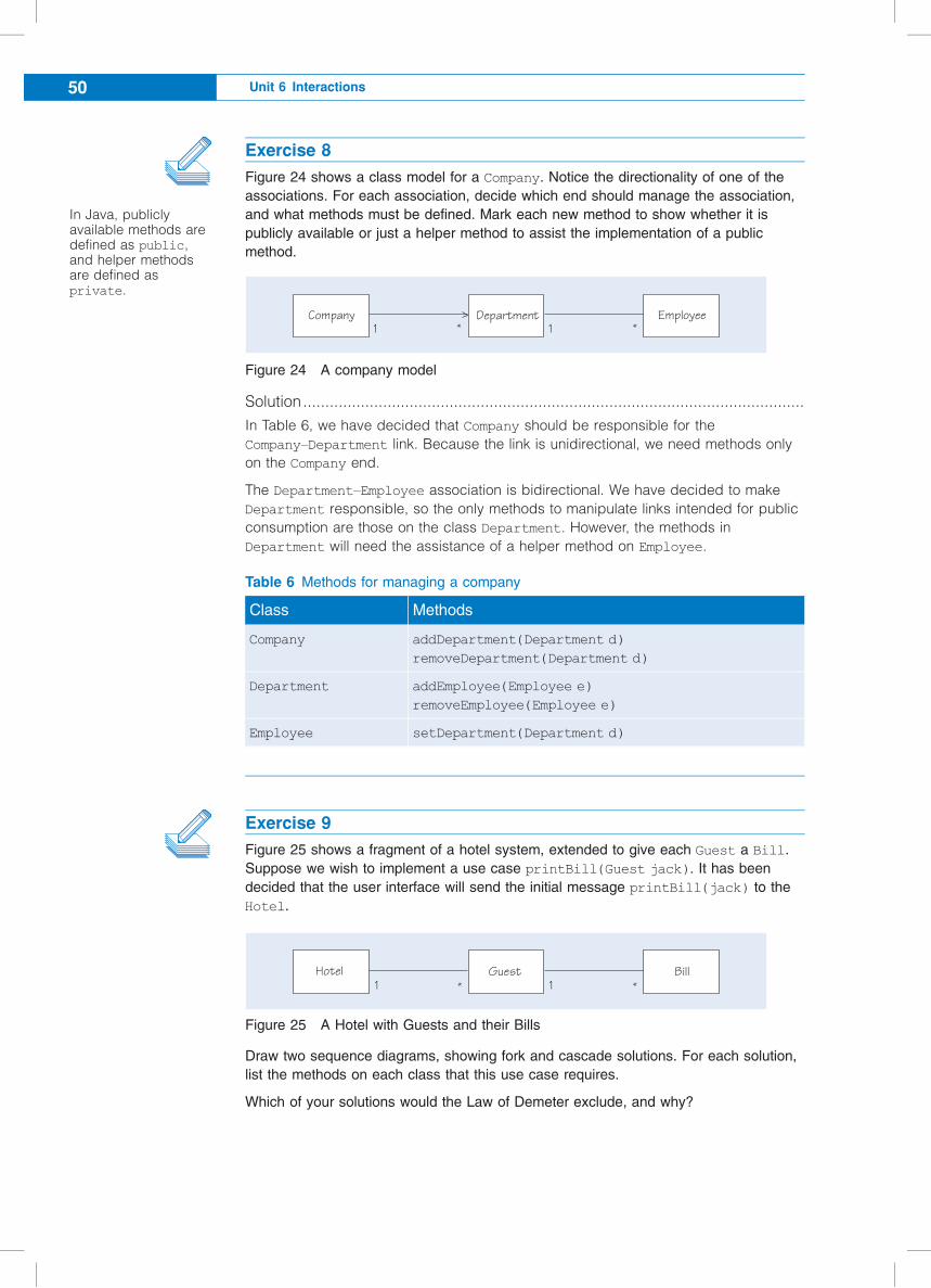
Exercise 8
Figure 24 shows a class model for a Company. Notice the directionality of one of the
associations. For each association, decide which end should manage the association,
and what methods must be defined. Mark each new method to show whether it is
publicly available or just a helper method to assist the implementation of a public
method.
Figure 24 A company model
Solution.................................................................................................................
In Table 6, we have decided that Company should be responsible for the
Company–Department link. Because the link is unidirectional, we need methods only
on the Company end.
The Department–Employee association is bidirectional. We have decided to make
Department responsible, so the only methods to manipulate links intended for public
consumption are those on the class Department. However, the methods in
Department will need the assistance of a helper method on Employee.
Table 6 Methods for managing a company
Class Methods
Company addDepartment(Department d)
removeDepartment(Department d)
Department addEmployee(Employee e)
removeEmployee(Employee e)
Employee setDepartment(Department d)
Exercise 9
Figure 25 shows a fragment of a hotel system, extended to give each Guest a Bill.
Suppose we wish to implement a use case printBill(Guest jack). It has been
decided that the user interface will send the initial message printBill(jack) to the
Hotel.
Figure 25 A Hotel with Guests and their Bills
Draw two sequence diagrams, showing fork and cascade solutions. For each solution,
list the methods on each class that this use case requires.
Which of your solutions would the Law of Demeter exclude, and why?
Company* *
Department Employee11
1*Hotel Guest Bill
*1
In Java, publiclyavailable methods aredefined as public,and helper methodsare defined asprivate.
Unit 6 Interactions50
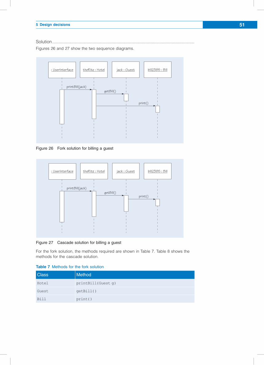
Solution.................................................................................................................
Figures 26 and 27 show the two sequence diagrams.
Figure 26 Fork solution for billing a guest
Figure 27 Cascade solution for billing a guest
For the fork solution, the methods required are shown in Table 7. Table 8 shows the
methods for the cascade solution.
Table 7 Methods for the fork solution
Class Method
Hotel printBill(Guest g)
Guest getBill()
Bill print()
: UserInterface theRitz : Hotel jack : Guest bill2385 : Bill
printBill(jack)getBill()
print()
: UserInterface theRitz : Hotel jack : Guest bill2385 : Bill
printBill(jack)getBill()
print()
5 Design decisions 51
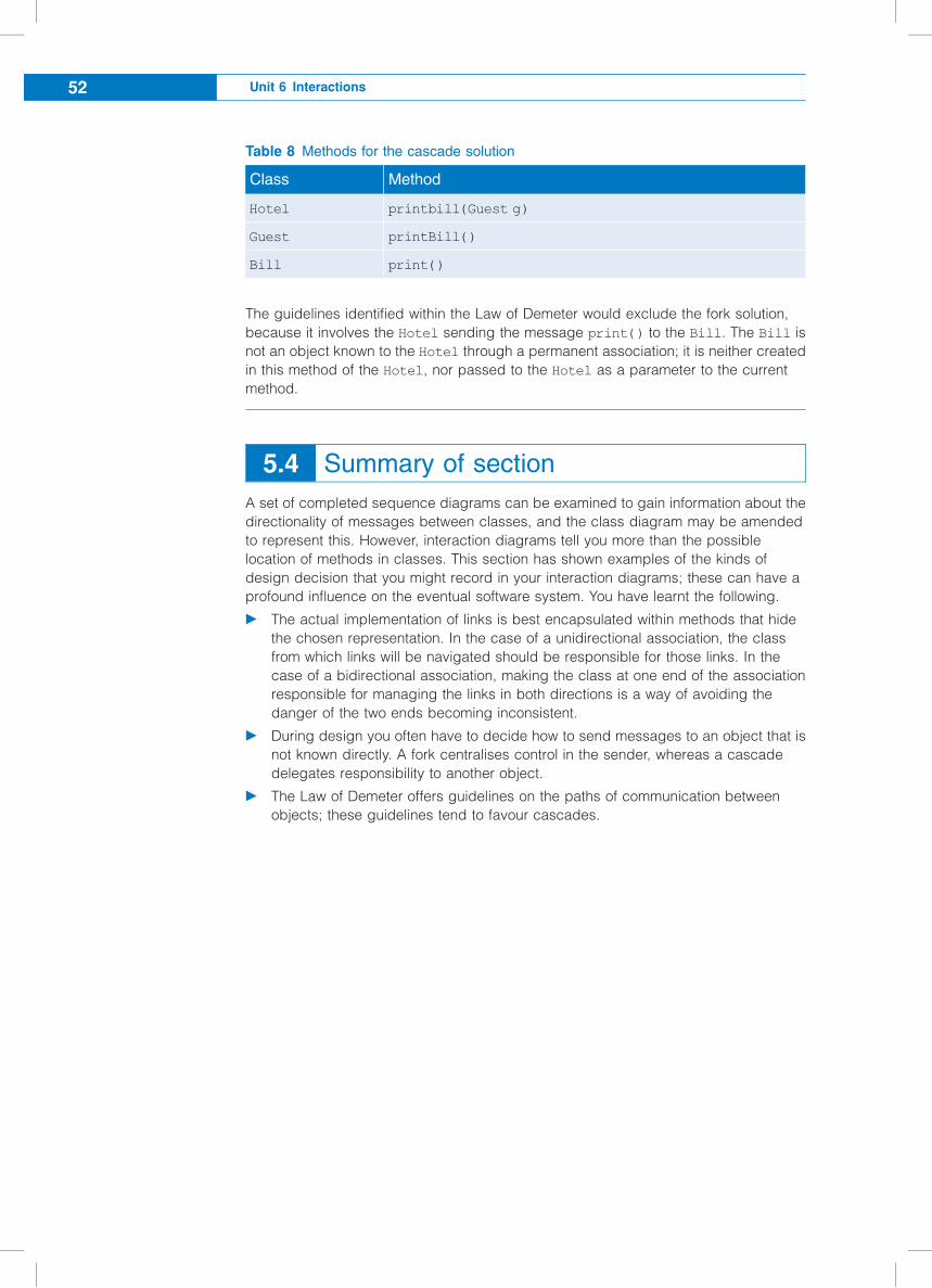
Table 8 Methods for the cascade solution
Class Method
Hotel printbill(Guest g)
Guest printBill()
Bill print()
The guidelines identified within the Law of Demeter would exclude the fork solution,
because it involves the Hotel sending the message print() to the Bill. The Bill is
not an object known to the Hotel through a permanent association; it is neither created
in this method of the Hotel, nor passed to the Hotel as a parameter to the current
method.
5.4 Summary of section
A set of completed sequence diagrams can be examined to gain information about the
directionality of messages between classes, and the class diagram may be amended
to represent this. However, interaction diagrams tell you more than the possible
location of methods in classes. This section has shown examples of the kinds of
design decision that you might record in your interaction diagrams; these can have a
profound influence on the eventual software system. You have learnt the following.
c The actual implementation of links is best encapsulated within methods that hide
the chosen representation. In the case of a unidirectional association, the class
from which links will be navigated should be responsible for those links. In the
case of a bidirectional association, making the class at one end of the association
responsible for managing the links in both directions is a way of avoiding the
danger of the two ends becoming inconsistent.
c During design you often have to decide how to send messages to an object that is
not known directly. A fork centralises control in the sender, whereas a cascade
delegates responsibility to another object.
c The Law of Demeter offers guidelines on the paths of communication between
objects; these guidelines tend to favour cascades.
Unit 6 Interactions52
6 Summary
Dynamic modelling is used to decide upon and document the message traffic that is
intended to implement the system changes required by use cases, and results in
assigning operations to the classes in the class model. In this unit, you have seen how
pre- and postconditions (assertions) can be used to specify operations, and that such
assertions can be identified by applying a design approach based on the notion of
contracts.
Sequence diagrams and communication diagrams (both types of interaction diagram)
describe the dynamic nature of a design in terms of the messages passed between
objects. They capture the same kind of information, but have different advantages in
what they explain visually.
During this stage of design, decisions must be made on where the different parts of
the system functionality should be placed. At the detailed level, we have to decide on
detailed patterns of messages, and the Law of Demeter offers some suggestions,
which can minimise dependencies between classes.
6 Summary 53

LEARNING OUTCOMES
On completion of this unit you should be able to:
c explain the benefits of using a design approach based on the idea of contracts;
c construct a sequence diagram showing which messages implement a use case;
c construct a communication diagram showing the same information;
c make informed choices between different possible designs;
c apply some principles which will help you to decide the classes that should
implement system functionality.
Unit 6 Interactions54

ReferencesLarman, C. (2002) Applying UML and Patterns: An Introduction to Object-Oriented
Analysis and Design and the Unified Process, 2nd edn, Upper Saddle River, NJ,
Prentice Hall.
Pressman, R. S. and Ince, D. (2000) Software Engineering: A Practitioner’s Approach,
5th edn (European adaptation), Maidenhead, McGraw-Hill.
6 References 55

IndexA
activations 23
assertions 7
B
bidirectional associations 46
C
Cascade pattern 48
communication diagrams 16, 31
compilers 8
contracts 9
correctness of software 7
Creator pattern (GRASP) 21
critical systems 8
D
defects 8
delegation of class
responsibilities 27
Design by Contract
assertions 7
correctness of software 7
Design by Contract (DbC) 6
design decisions 43
dynamic modelling 16
dynamic tools 8
E
Expert pattern (GRASP) 21
F
Fork pattern 48
formal technical reviews (FTRs) 8
G
GRASP (General Responsibility
Assignment Software Patterns) 21
Creator pattern 21
Expert pattern 21
I
Information Expert pattern 21
interaction diagrams 16
L
Law of Demeter 49
M
message numbers 33
N
navigability 43
P
procedural interactions 23
prototypical interactions 35
prototypical objects 35
S
sequence diagrams 16
static analysis tools 8
Strategy pattern 27
subcommunications 39
T
testing 8
Unit 6 Interactions56


