Embed Size (px)
Citation preview

User Guide: FEA of Bolted Joints A Seminar for Simulation Engineers
George Laird, PhD, PE – Principal Mechanical Engineer

User Guide: FEA of Bolted Joints 2018
AppliedCAx.com / Predictive Engineering - Please share with your friends and visit us online at www.AppliedCAx.com Page 2 of 35

User Guide: FEA of Bolted Joints 2018
AppliedCAx.com / Predictive Engineering - Please share with your friends and visit us online at www.AppliedCAx.com Page 3 of 35

User Guide: FEA of Bolted Joints 2018
AppliedCAx.com / Predictive Engineering - Please share with your friends and visit us online at www.AppliedCAx.com Page 4 of 35

User Guide: FEA of Bolted Joints 2018
AppliedCAx.com / Predictive Engineering - Please share with your friends and visit us online at www.AppliedCAx.com Page 5 of 35
TABLE OF CONTENTS 1. FEA OF BOLTED JOINTS: WHAT THIS SEMINAR IS ABOUT ............................................................................................. 7
1.1 WHAT WE WILL COVER .............................................................................................................................................................................. 7
1.2 WHAT WE DON’T COVER ............................................................................................................................................................................ 7
2. WHAT WE KNOW ......................................................................................................................................................... 8
3. WHY ALL BOLT MODELING HAS IT CHALLENGES ........................................................................................................ 12
3.1 LET’S START WITH THE OBVIOUS – THERE IS A HOLE ....................................................................................................................................... 12
But What Does This Have To Do With Our Bolt Modeling?......................................................................................................... 13 3.1.13.1.1.1 What if we have a non-perfect bolt fit?............................................................................................................................................ 14
How Adequate is the RBE Idealization? ...................................................................................................................................... 15 3.1.23.1.2.1 But Wait, We Could Use a RBE3! ...................................................................................................................................................... 16
3.2 IN SUMMARY: ABOUT PLATES WITH HOLES WITH BOLTS ................................................................................................................................... 17
But the Reality Is: Airframe Stress Analysis and Sizing by M.C. Niu ............................................................................................. 18 3.2.1
4. THE BOLTED LAP JOINT .............................................................................................................................................. 19
4.1 LET’S START WITH REALITY: THE 3D BOLT MODEL .......................................................................................................................................... 20
3D Stress Results: Tension (250 lbf) ........................................................................................................................................... 21 4.1.1 3D Stress Results: Bending ......................................................................................................................................................... 22 4.1.2
4.1.2.1 No Bolt Preload / No Friction ........................................................................................................................................................... 22 4.1.2.2 Bolt Preload with Friction ................................................................................................................................................................. 23
4.2 LAP JOINT BOLTING WITH BEAM AND RBE ELEMENTS ...................................................................................................................................... 24
Tension Loading ......................................................................................................................................................................... 24 4.2.14.2.1.1 Edge Connection .............................................................................................................................................................................. 24 4.2.1.2 Washer Connection .......................................................................................................................................................................... 25
Summary: What do we know about Bolted Lap Joints under Tension? ...................................................................................... 26 4.2.2 Bending ..................................................................................................................................................................................... 27 4.2.3

User Guide: FEA of Bolted Joints 2018
AppliedCAx.com / Predictive Engineering - Please share with your friends and visit us online at www.AppliedCAx.com Page 6 of 35
4.2.3.1 Edge Connection .............................................................................................................................................................................. 27
4.2.3.2 Washer Connection .......................................................................................................................................................................... 29
Summary: What do we know about Bolted Lap Joints under Bending ........................................................................................ 31 4.2.4
5. SOME COMMENTS ..................................................................................................................................................... 32
5.1 LET’S JUST CUT TO THE CHASE .................................................................................................................................................................... 32
What About Bolt Bending Stresses? ........................................................................................................................................... 32 5.1.15.2 WHAT ABOUT VIBRATION: RBE2 OR RBE3 OR WITH BOLT PRELOAD? ................................................................................................................. 34
What About Bolt Preload? ......................................................................................................................................................... 34 5.2.15.3 FATIGUE ANALYSIS OF BOLTED CONNECTIONS, I.E., THE BOLT ............................................................................................................................ 35
5.4 API OF THE MONTH ................................................................................................................................................................................. 35

User Guide: FEA of Bolted Joints 2018
AppliedCAx.com / Predictive Engineering - Please share with your friends and visit us online at www.AppliedCAx.com Page 7 of 35
1. FEA OF BOLTED JOINTS: WHAT THIS SEMINAR IS ABOUT
The literature has plenty of information on the modeling of bolts. It is the usual story about compromise versus accuracy or do I throw a beam/RBE at it (super-simple and efficient) or go full 3D with contact (super-slow and numerically expensive). We know that if someone wants to throw stones at your model, a reviewer can easily critique your model for using beam/RBE combinations to model a bolted joints whereas a 3D approach is more or less bomb-proof. But this is engineering and not pie-in-the-sky and we have to get our models built with reasonable accuracy and out-the-door.
1.1 WHAT WE WILL COVER o Why all bolt modeling has it challenges o Basic problems with linear analysis of bolted connections
▫ Is the loading tensile or bending? ▫ What type of bolted joint?
o Linear and Nonlinear Analysis – the basic beam/RBE combination o Why going 3D is not always the answer and can be a trap o Fatigue analysis of bolted joints (don’t get your hopes up, but we’ll make a few comments)
1.2 WHAT WE DON’T COVER Nothing to do with spot welding since it is another class of joints No discussion on what is the best connection for all bolted connections since there is no best idealized connection No proprietary software/solution that promises bolt connection nirvana

User Guide: FEA of Bolted Joints 2018
AppliedCAx.com / Predictive Engineering - Please share with your friends and visit us online at www.AppliedCAx.com Page 8 of 35
2. WHAT WE KNOW A selection of some consulting projects at Predictive Engineering that have had bolt modeling challenges:
3,000 HP 8-Speed Transmission Bolted Flanges Norton Motorcycle Crankcase
Open-Pit Mining Apron Conveyor Off-Shore, High-Speed Winch 100 kW Wind Turbine Tower

User Guide: FEA of Bolted Joints 2018
AppliedCAx.com / Predictive Engineering - Please share with your friends and visit us online at www.AppliedCAx.com Page 9 of 35
Bus Seat 16-g Airplane Attendant Seat Research Satellite
Close-Up View of Bolted Connection 16 g Crash Analysis Airplane Divan Seat

User Guide: FEA of Bolted Joints 2018
AppliedCAx.com / Predictive Engineering - Please share with your friends and visit us online at www.AppliedCAx.com Page 10 of 35
Composite Aviation Container Magnetic Bearing 500 kW Generator
Helicopter Tail Rotor with Bolted Connection High-Temp Furnace Bolted Connection

User Guide: FEA of Bolted Joints 2018
AppliedCAx.com / Predictive Engineering - Please share with your friends and visit us online at www.AppliedCAx.com Page 11 of 35
3. WHY ALL BOLT MODELING HAS IT CHALLENGES 3.1 LET’S START WITH THE OBVIOUS – THERE IS A HOLE
Stress Flows ∅+ 2 ∅ + ∅ = 0
With Pure Shear – Stress Concentration 4x
Images courtesy of www.FractureMechanics.org

User Guide: FEA of Bolted Joints 2018
AppliedCAx.com / Predictive Engineering - Please share with your friends and visit us online at www.AppliedCAx.com Page 12 of 35
BUT WHAT DOES THIS HAVE TO DO WITH OUR BOLT MODELING? 3.1.1Let’s assume that our bolted joint is loaded in pure tension. If we narrow our scope to just one bolt in a wide plate, then one can visual the load transfer to the plate as a sinusoidal function where the peak bearing pressu re is aligned with the direction of the tensile load. Let’s show some stress images:
Bearing Load (250 lbf) to Mimic Bolt Max Pressure Aligned with Tensile Load
Von Mises Stress – 2,900 psi Maximum Principal Stress (σ1) – 2,900 psi

User Guide: FEA of Bolted Joints 2018
AppliedCAx.com / Predictive Engineering - Please share with your friends and visit us online at www.AppliedCAx.com Page 13 of 35
3.1.1.1 WHAT IF WE HAVE A NON-PERFECT BOLT FIT?
Bearing Load (250 lbf) to Mimic Bolt - Load Applied Over 45 Degree Region
Von Mises Stress – Hot Spot – Not Useful Maximum Principal Stress (σ1) – 3,400 psi

User Guide: FEA of Bolted Joints 2018
AppliedCAx.com / Predictive Engineering - Please share with your friends and visit us online at www.AppliedCAx.com Page 14 of 35
HOW ADEQUATE IS THE RBE IDEALIZATION? 3.1.2Let’s take the same model and replace the bearing load with a RBE2. The RBE2 is constrained (6 DOF) at its independent node at the center of the hole while at the far end, a load of 250 lbf is applied. The results speak for themselves in comparison to the more realistic idealization using a bearing force.
Same Load of 250 lbf RBE2 with Independent Node Fixed
Von Mises Stress – 1,200 psi Maximum Principal Stress (σ1) – 1400 psi

User Guide: FEA of Bolted Joints 2018
AppliedCAx.com / Predictive Engineering - Please share with your friends and visit us online at www.AppliedCAx.com Page 15 of 35
3.1.2.1 BUT WAIT, WE COULD USE A RBE3! Since this question would naturally come up, had to show that the results are not any better just more confusion.
RBE3 – Force Interpolation Element
Von Mises Stress – 2,500 psi Principal Stress (σ1) – 1,700 psi

User Guide: FEA of Bolted Joints 2018
AppliedCAx.com / Predictive Engineering - Please share with your friends and visit us online at www.AppliedCAx.com Page 16 of 35
3.2 IN SUMMARY: ABOUT PLATES WITH HOLES WITH BOLTS If you put a hole in a plate and pull on it, you have a stress concentration of 3x. A little side note is that one often knocks downs composite data by 3x to set margins. This makes sense given that most composite structures have holes d rilled into them and likewise why it is common to use inserts to spread out the connection bearing load.
Holes are stress concentrations If you pull on a plate with a hole, you have a 3x effect The bending stress field is likewise bumped up by 3x
Don’t get your hopes up that any idealization technique will get you even close to the true stress state around a bolted hole (we’ll get more into this later), that is, keep in mind that the RBE idealization may provide stresses that are lower than reality.
Idealization Von Mises Stress, psi Maximum Principal Stress, psi
Bearing Load Idealization - 180° 2,900 2,900 Bearing Load Idealization - 45° not useful 3,400
RBE2 1,200 1,400 RBE3 2,500 1,700
Reality ? ?

User Guide: FEA of Bolted Joints 2018
AppliedCAx.com / Predictive Engineering - Please share with your friends and visit us online at www.AppliedCAx.com Page 17 of 35
BUT THE REALITY IS: AIRFRAME STRESS ANALYSIS AND SIZING BY M.C. NIU 3.2.1
Design for Tension and Shear Tear Out Material Bearing Loads

User Guide: FEA of Bolted Joints 2018
AppliedCAx.com / Predictive Engineering - Please share with your friends and visit us online at www.AppliedCAx.com Page 18 of 35
4. THE BOLTED LAP JOINT Our test case is the lap joint where we will pull it and bend it. This is our foundation and but is sufficiently complex to get lost in the weeds.
Thinking About Load Application to a Bolted Joint

User Guide: FEA of Bolted Joints 2018
AppliedCAx.com / Predictive Engineering - Please share with your friends and visit us online at www.AppliedCAx.com Page 19 of 35
4.1 LET’S START WITH REALITY: THE 3D BOLT MODEL Stress flows (i.e., Airy Stress Function) and since structures are 3D, we’ll build up a full-on 3D model with contact. The model follows the dimensions for the simple plate discussed in the prior section at 8” L, 2” W and ¼” Thk. The hole diameter is 0.5” with a bolt diameter of 0.48”. The plates are overlapped by 2.0”. The bolt head is 0.75” in diameter. For good measure, a 0.05” thick washer with a diameter of 0.9” was added. Contact was enforced across all parts.

User Guide: FEA of Bolted Joints 2018
AppliedCAx.com / Predictive Engineering - Please share with your friends and visit us online at www.AppliedCAx.com Page 20 of 35
3D STRESS RESULTS: TENSION (250 LBF) 4.1.1The bolt is given just a small amount of preload (10 psi) to snug up the plates, washers and bolt heads. The 250 lbf load is then applied.
3D Model with 250 lbf Tension Load – Constrained Far End Stress Results – Deflection Scaled 25x
Von Mises Stress 18,000 psi Max. Principal Stress 6,600 psi
User Guide: FEA of Bolted Joints 2018
AppliedCAx.com / Predictive Engineering - Please share with your friends and visit us online at www.AppliedCAx.com Page 21 of 35
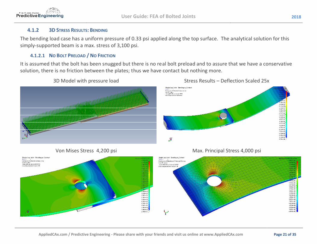
3D STRESS RESULTS: BENDING 4.1.2The bending load case has a uniform pressure of 0.33 psi applied along the top surface. The analytical solution for this simply-supported beam is a max. stress of 3,100 psi.
4.1.2.1 NO BOLT PRELOAD / NO FRICTION It is assumed that the bolt has been snugged but there is no real bolt preload and to assure that we have a conservative solution, there is no friction between the plates; thus we have contact but nothing more.
3D Model with pressure load Stress Results – Deflection Scaled 25x
Von Mises Stress 4,200 psi Max. Principal Stress 4,000 psi

User Guide: FEA of Bolted Joints 2018
AppliedCAx.com / Predictive Engineering - Please share with your friends and visit us online at www.AppliedCAx.com Page 22 of 35
4.1.2.2 BOLT PRELOAD WITH FRICTION Here we crank down the bolt preload to lock the plates together.
Von Mises Stress 4,800 psi Max. Principal Stress 3,300 psi

User Guide: FEA of Bolted Joints 2018
AppliedCAx.com / Predictive Engineering - Please share with your friends and visit us online at www.AppliedCAx.com Page 23 of 35
4.2 LAP JOINT BOLTING WITH BEAM AND RBE ELEMENTS TENSION LOADING 4.2.1
We are modeling the bolt head and nut in two ways: (i) At the edge and (ii) As a pseudo-washer.
4.2.1.1 EDGE CONNECTION
RBE2 RBE3
Von Mises 9,000 psi Von Mises 8,700 psi
Maximum Principal 10,000 psi Maximum Principal 7,000 psi

User Guide: FEA of Bolted Joints 2018
AppliedCAx.com / Predictive Engineering - Please share with your friends and visit us online at www.AppliedCAx.com Page 24 of 35
4.2.1.2 WASHER CONNECTION
RBE2 RBE3
Von Mises 6,700 psi Von Mises 6,700 psi
Maximum Principal 7,600 psi Maximum Principal 6,600 psi

User Guide: FEA of Bolted Joints 2018
AppliedCAx.com / Predictive Engineering - Please share with your friends and visit us online at www.AppliedCAx.com Page 25 of 35
SUMMARY: WHAT DO WE KNOW ABOUT BOLTED LAP JOINTS UNDER TENSION? 4.2.2
Idealization Von Mises Stress, psi Max. Principal Stress, psi
Plate with Hole – Tension Load
Bearing Load Idealization - 180° 2,900 2,900 Bearing Load Idealization - 45° not useful 3,400
RBE2 1,200 1,400 RBE3 2,500 1,700
Lap Joint Model - Tension
3D Solid Model 18,000 (compressive) 6,600 2D Shell Model – Beam/RBE2 - Edge 9,000 10,000 2D Shell Model – Beam/RBE3 - Edge 8,700 7,000 2D Shell Model – Beam/RBE2 - Washer 6,700 7,600 2D Shell Model – Beam/RBE3 - Washer 6,700 6,600

User Guide: FEA of Bolted Joints 2018
AppliedCAx.com / Predictive Engineering - Please share with your friends and visit us online at www.AppliedCAx.com Page 26 of 35
BENDING 4.2.34.2.3.1 EDGE CONNECTION
The same bending load as used in the 3D model is morphed over to the shell model.
4.2.3.1.1 EDGE CONNECTION / NO CONTACT WITH NO BOLT PRELOAD
RBE2 RBE3
Von Mises 6,800 psi Von Mises 6,400 psi
Maximum Principal 7,600 psi Maximum Principal 6,100 psi

User Guide: FEA of Bolted Joints 2018
AppliedCAx.com / Predictive Engineering - Please share with your friends and visit us online at www.AppliedCAx.com Page 27 of 35
4.2.3.1.1 EDGE CONNECTION / CONTACT WITH BOLT PRELOAD
BTW, with shell elements, the only out-of-plane stiffness we have is the bolt and some fuzzy contact spring stiffness. Thus, it is a far cry from reality where the stored elastic energy of the 3D plates (i.e., real structure) is part of the preload equation.
RBE2 RBE3
Von Mises 5,900 psi Von Mises 5,500 psi
Maximum Principal 6,600 psi Maximum Principal 5,500 psi

User Guide: FEA of Bolted Joints 2018
AppliedCAx.com / Predictive Engineering - Please share with your friends and visit us online at www.AppliedCAx.com Page 28 of 35
4.2.3.2 WASHER CONNECTION 4.2.3.2.1 WASHER CONNECTION / NO CONTACT WITH NO BOLT PRELOAD
RBE2 RBE3
Von Mises 5,000 psi Von Mises 4,900 psi
Maximum Principal 5,700 psi Maximum Principal 4,800 psi

User Guide: FEA of Bolted Joints 2018
AppliedCAx.com / Predictive Engineering - Please share with your friends and visit us online at www.AppliedCAx.com Page 29 of 35
4.2.3.2.2 WASHER CONNECTION / CONTACT WITH BOLT PRELOAD
RBE2 RBE3
Von Mises 4,700 psi Von Mises 3,200 psi
Maximum Principal 5,300 psi Maximum Principal 3,300 psi

User Guide: FEA of Bolted Joints 2018
AppliedCAx.com / Predictive Engineering - Please share with your friends and visit us online at www.AppliedCAx.com Page 30 of 35
SUMMARY: WHAT DO WE KNOW ABOUT BOLTED LAP JOINTS UNDER BENDING
Idealization Von Mises Stress, psi Max. Principal Stress, psi
Lap Joint Model - Bending
3D Solid Model with Bolt Snug (Contact) 4,200 4,000 3D Solid Model with Bolt Preload (Contact) 4,800 3,300 2D Shell Model – Beam/RBE2 - Edge 6,800 7,600 2D Shell Model – Beam/RBE3 - Edge 6,400 6,100 2D Shell Model – Beam/RBE2 – Edge w/Contact 5,900 6,600 2D Shell Model – Beam/RBE3 – Edge w/Contact 5,500 5,500 2D Shell Model – Beam/RBE2 - Washer 5,000 5,700 2D Shell Model – Beam/RBE3 - Washer 4,900 4,800 2D Shell Model – Beam/RBE2 – Washer w/Contact 4,700 5,300 2D Shell Model – Beam/RBE3 – Washer w/Contact 3,200 3,300
4.2.4

User Guide: FEA of Bolted Joints 2018
AppliedCAx.com / Predictive Engineering - Please share with your friends and visit us online at www.AppliedCAx.com Page 31 of 35
5. SOME COMMENTS 5.1 LET’S JUST CUT TO THE CHASE
What are some thoughts on how to handle a bolted connection?
Niu Spreadsheet Analysis – Axial and Shear Forces
WHAT ABOUT BOLT BENDING STRESSES? We don’t. Although one can add a bending stress component by taking the shear force and assuming a contact gap between the bolt shank the plates (e.g., 0.01”) and thus via your spreadsheet analysis, include a bending stress. This information courtesy of EneavorAnalysis.com
5.1.1

User Guide: FEA of Bolted Joints 2018
AppliedCAx.com / Predictive Engineering - Please share with your friends and visit us online at www.AppliedCAx.com Page 32 of 35
5.2 WHAT ABOUT VIBRATION: RBE2 OR RBE3 OR WITH BOLT PRELOAD?
RBE2 (washer) 56 Hz RBE3 (washer) 52 Hz 3D 47 Hz
WHAT ABOUT BOLT PRELOAD?
Yes – it can be added and yes it does change the results (see FEMAP User Guide Section 8.8.1.9) . What is the right answer? Most likely closer to the 3D model.
Model 1st 2nd 3rd 4th 5th
RBE2 471 / 472 Hz 239 / 333 480 / 481 493 / 562 554 / 991
RBE3 43 / 44 Hz 234 / 318 432 / 444 480 / 540 530 / 937
3D 47 Hz 236 479 499 645
3D Transient 47 Hz time step 0.001 sec, hence tight resolution to 100 Hz (10 points per cycle) 1Regular linear analysis 2Pre-stiffened (bolt preload with contact)
5.2.1

User Guide: FEA of Bolted Joints 2018
AppliedCAx.com / Predictive Engineering - Please share with your friends and visit us online at www.AppliedCAx.com Page 33 of 35
5.3 FATIGUE ANALYSIS OF BOLTED CONNECTIONS, I.E., THE BOLT We do our fatigue analysis on bolts via spreadsheet. It is not fancy but it gets the job done. What is the first step? Getting the information out of FEMAP and into the spreadsheet.
5.4 API OF THE MONTH


