Embed Size (px)
Citation preview
This article was downloaded by: [KAUSHIK KUMAR]On: 06 July 2012, At: 06:26Publisher: Taylor & FrancisInforma Ltd Registered in England and Wales Registered Number: 1072954 Registered office: Mortimer House,37-41 Mortimer Street, London W1T 3JH, UK
Virtual and Physical PrototypingPublication details, including instructions for authors and subscription information:http://www.tandfonline.com/loi/nvpp20
Virtual manufacturing of various types of gears andvalidation of the technique using rapid prototypeG. Pohit a & K. Kumar ba Department of Mechanical Engineering, Jadavpur University, Kolkata, 700032, Indiab Department of Polymer Engineering, Birla Institute of Technology, Mesra, Ranchi, India
Version of record first published: 20 Jun 2012
To cite this article: G. Pohit & K. Kumar (2012): Virtual manufacturing of various types of gears and validation of thetechnique using rapid prototype, Virtual and Physical Prototyping, 7:2, 153-171
To link to this article: http://dx.doi.org/10.1080/17452759.2012.686696
PLEASE SCROLL DOWN FOR ARTICLE
Full terms and conditions of use: http://www.tandfonline.com/page/terms-and-conditions
This article may be used for research, teaching, and private study purposes. Any substantial or systematicreproduction, redistribution, reselling, loan, sub-licensing, systematic supply, or distribution in any form toanyone is expressly forbidden.
The publisher does not give any warranty express or implied or make any representation that the contentswill be complete or accurate or up to date. The accuracy of any instructions, formulae, and drug doses shouldbe independently verified with primary sources. The publisher shall not be liable for any loss, actions, claims,proceedings, demand, or costs or damages whatsoever or howsoever caused arising directly or indirectly inconnection with or arising out of the use of this material.
Virtual manufacturing of various types of gears and validation of thetechnique using rapid prototype
A method to simulate gear manufacturing process with chip formation and amethod to validate the simulation by using rapid prototyping techniques are
presented in this paper
G. Pohita* and K. Kumarb
aDepartment of Mechanical Engineering, Jadavpur University, Kolkata 700032, IndiabDepartment of Polymer Engineering, Birla Institute of Technology, Mesra, Ranchi, India
(Received 10 June 2011; final version received 17 April 2012)
Virtual manufacturing of gears is carried out to illustrate the fairly complicated gear
generation process and the associated simultaneous motions being provided to the gear
blank and the gear cutter. An attempt has been made to capture the phenomenon of chip
formation as well. Generation of various types of gears are shown employing two types of
operation, one being use of a gear hobbing cutter having multiple cutting edges. As such
validation of the virtual manufacturing technique is always a difficult task. Using rapid
prototype technology, a novel approach is proposed to ascertain the efficacy of the virtual
manufacturing process being followed. The methodology is quite general and can be used
for validation of any other virtual manufacturing process as well.
Keywords: virtual manufacturing; gear cutting; chip formation
Introduction
Virtual reality is an artificial environment that is created by
means of software in such a fashion that the user accepts it
as a real environment. The majority of the current virtual
reality environments are primarily visual experiences dis-
played on a computer screen. Virtual reality can be the
development of an imagined environment, for example, a
game or interactive story or simulation of a real environ-
ment for training and education. The growing develop-
ments in virtual reality (VR) systems have created a growing
potential for applications of VR in product design, as an
ancillary tool for engineering in simulating complicated
manufacturing processes, for development of product pro-
totypes etc. Gears are extensively used in industry for
transmission of power. In order to meet the difficult service
condition, the gear should have robust construction, close
dimensional tolerance, reliable performance and long life.
By virtue of its configurations, gear manufacturing has
become not only a specialised field but also a fairly
complicated operation. People may find it difficult to
understand the complex geometries and the manufacturing
arrangement of different gear manufacturing processes
from two-dimensional sketches generally provided in text
books. However, the clarity of the complex gear generation
process and the associated simultaneous motions of the
gear blank and the gear cutter can be represented very
efficiently with the help of the virtual manufacturing
technique. In a recent paper (Willis 1993), the state of the
*Corresponding author. Email: [email protected]
Virtual and Physical Prototyping, Vol. 7, No. 2, June 2012, 153�171
Virtual and Physical PrototypingISSN 1745-2759 print/ISSN 1745-2767 online # 2012 Taylor & Francis
http://www.tandfonline.comhttp://dx.doi.org/10.1080/17452759.2012.686696
Dow
nloa
ded
by [
KA
USH
IK K
UM
AR
] at
06:
26 0
6 Ju
ly 2
012
art VR applied in the field of design and manufacturing
process is dealt with in a comprehensive manner.
Like any other manufacturing processes, chip formation
and chip breaking mechanism play vital roles while
simulating any kind of gear manufacturing operation.
Starting from the Merchant chip formation model in
1945, many researchers have focused their attention on
understanding the phenomenon based on simple cutting
tools having the same tool geometry and cutting parameters
along the cutting edge. However, in the case of the gear
cutting process, it is a bit more complicated as geometry
and cutting parameters differ along the cutting edges. A
considerable amount of literature is available on virtual
manufacturing of different engineering components and
chip formation during cutting operation in an open
domain. They are presented in the following section.
Balyliss and Bowler (1994) presented a seminar at CSG 94
conference on theoretic solid modelling techniques using the
VM tools like VRML (Virtual Reality Manufacturing
Language). They have developed solid modeller SVLIS
written in C�� language and used it for a 3 axis numerical
control (NC) mill. The modelling technologies had been
developed by Kimera (1993) using product and process
modelling as a kernel for a virtual manufacturing environ-
ment. In his work Kimura has incorporated significant
modelling issues like representation, representation language,
abstraction, standardisation, reuse and configuration control.
Taylor (1994) has performed work on animation. He
imported the two-dimensional (2D) drawing from the AUTO-
CAD to the 3D-STUDIO-MAX and later by using the vital
animation tool of 3D-STUDIO-MAX, has done almost all
possible arrangements of objects and subsequently imparted
motion to them. A prototype of distributed simulation
manager is developed by Iwata et al. (1995) in real-time
processing for Transmission control protocol with adaptive
spacing (TCPAP) information networks. Gooch (1998) has
developed different types of ‘spindle-bearing’ arrangements
using the modelling techniques of virtual design and manu-
facturing on a platform of 3D- STUDIO-MAX. Pradhan and
Huang (1998) developed a virtual manufacturing information
system using Java, Java Database Connectivity and a properly
selected middleware. Tesic and Banerjee (1999) have worked in
the area of rapid prototyping, which is a new technology for
design, visualisation and verification. Graphical user inter-
faces, virtual reality technologies, distillation, segregation and
auto interpretation are some of the important features of their
work. Arangarasan (2000) contributed towards virtual proto-
typing using simulation of the planned production process on
a platform of MAYA, 3D- STUDIO-MAX and VRML etc.
Bao et al. (2002) proposed a scheme for modelling a
revolving milling cutter using the virtual manufacturing
technique. Jezernik and Hren (2003) worked for a solution
to integrate computer-aided design (CAD) and virtual reality
(VR) databases in design and manufacturing processes. They
described a system for VRML model visualisation that
enables changes in the configuration file that automatically
reviews the model including the functional behaviour.
Due to the complicated tooth geometry of worm gears,
the design process is often a tedious task. The researcher
(Baykasoglu 2003) developed an integrated approach con-
sisting of numerical analysis, virtual simulation and finite
element analysis to obtain a favourable result. Choi and
Chan (2004) proposed a virtual prototyping (VP) system
that integrates virtual reality with rapid prototyping (RP)
to create virtual or digital prototypes to facilitate product
development. In addition to numerical quantification of the
simulation results, the system also provided stereoscopic
visualisation of the product design and its prototype for
detailed analyses. Yao et al. (2006) obtained satisfactory
results by representing the machining error due to the
turning operation on a virtual work piece. Luo et al. (2010)
researched behaviour simulation of a multi-axis computer
numerical control (CNC) machine tool in a virtual environ-
ment. A virtual reality machine shop environment (Bilalis
et al. 2009) was developed and integrated with a graphical
model for the calculation of quantitative data affecting the
roughness of a machined surface. A comprehensive litera-
ture review (Cecil and Kanchanapiboon 2007) has been
given on virtual prototyping research efforts in various
engineering domains, including design and manufacturing.
At Jadavpur University, research work (Roy et al. 2003,
Pattanayak et al. 2003, Pohit 2006, Kumar et al. 2007a, 2007b)
have been being carried out to simulate the gear manufacturing
processes using AUTOCAD and 3D-STUDIO-MAX as the
platform. Computer simulation was very effectively used to
view and subsequently analyse the different complicated
manufacturing processes using the concept of design centred
virtual manufacturing. Gear teeth (Pohit 2006) had been
generated by a rack cutter following the principle of gear
shaping. The work does not include the simulation of chip
formation during the cutting operation. However, in subse-
quent papers (Kumar et al. 2008), a disc type form cutter is
employed for the gear cutting operation and the formation of
chip during the gear cutting operation is also captured in an
animated view. The software was developed using MAXScript,
an object contained programming language that can be run in
the 3D-STUDIO-MAX environment.
Since the aim of the present work is also to capture the
phenomenon of chip formation using virtual reality, a few
selected publications relevant to the present work are cited
here. Arshinov and Alekseev (1976) mentioned the type of
chip being generated with respect to various materials along
with the other aspects of chip formation. Later, Khanna
(1981) illustrated the basic mechanism by which chips are
formed during the gear cutting and the various equations
governing the path, chip formation and the type of chips.
Young et al. (1987) modified the approach of Okushima
and Minato (1959) assuming the magnitude of the friction
154 G. Pohit and K. Kumar
Dow
nloa
ded
by [
KA
USH
IK K
UM
AR
] at
06:
26 0
6 Ju
ly 2
012
force for the chip produced by each element along the
cutting edge to be proportional to the corresponding uncut
chip area. Bouzakis et al. (2008) created Finite element
modeling (FEM)-supported simulation of chip formation
and flow in gear hobbing of spur and helical gears. They
created an integrated procedure for simulating the compli-
cated chip formation and flow in gear hobbing. Hortig and
Svendsen (2007) simulated chip formation during high-
speed cutting.
It has been found from the literature review that spur and
helical gears had been created using a disc type form cutter
in a virtual environment. In a particular case (Kumar et al.
2008), simulation of chip formation phenomenon during
gear cutting had also been displayed with illustrations.
However, no attempt has so far been made to simulate
relatively complicated gear manufacturing processes, for
example, creation of bevel gear or generation of gears
through hobbing. In addition, another major aspect
pertaining to the entire process has not been addressed at
all. From a visual aspect, the software seems to be quite
efficient in depicting different gear manufacturing pro-
cesses. However, users may not be able to ascertain the
degree of accuracy of the virtual gear thus produced. In
other words, whether the profile of the gear matches well
with the involute curve as has been assumed during the
virtual manufacturing operation or whether or not dimen-
sional accuracy of the product is properly maintained.
In the present paper, an attempt has been made to project
the entire procedure of spur, helical, and bevel gear
manufacturing using a form cutter in a virtual environment.
The software also includes the generation process of a spur
gear using a hob cutter. Special emphasis is provided on the
chip formation during the cutting operation except for the
bevel gear process.
Next, in order to validate the simulation process, an
arrangement is made to transform the virtual object into
reality using the rapid prototype technique. The dimensions
of these actual solid models are then compared with the
virtual gears to ascertain the accuracy of the gears produced
through the virtual manufacturing technique. The valida-
tion of the methodology and checking of the dimensional
accuracy of the object thus created by VR is achieved by
means of RP technology.
Methodology
The present work aims to develop user-friendly software to
animate different gear manufacturing processes highlight-
ing the intricacies of each technique. The number of
different gear-cutting processes is so many that it will be a
herculean task to cover the entire range of the spectrum.
Therefore, the present work is limited to the virtual gear
manufacturing of the following techniques:
(1) Creation of spur and helical gear with form milling
cutter
(2) Creation of bevel gear
(3) Generation of gear by hobbing
In general gears may have different types of tooth
profiles. The involute profile, being most common in
industry, is preferred for the present study. Before proceed-
ing to the details of virtual manufacturing techniques, it is
worthwhile to understand the principles underlying the
methods by which the gear teeth are generally produced.
Spur and helical gear using disc type form milling cutter
The detailed methodology being followed for the creation of
spur and helical gears using a disc type form milling cutter
has been described by Kumar et al. (2008). Various
simultaneous movements imparted to a gear blank and
cutter during cutting operations are also shown there. The
basic mechanism by which chips are formed during the gear
cutting operation has been illustrated with sufficient details.
These will not be repeated here. However, in the case of the
helical gear, selection of the cutter is not based on the virtual
number of teeth as has been outlined by Kumar (2010).
Bevel gear using disc type form milling cutter
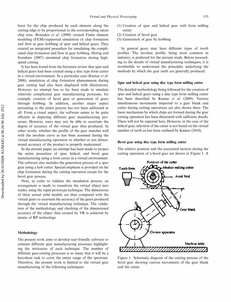
The relative position and the associated motion during the
cutting operation of a bevel gear are shown in Figure 1. A
Figure 1. Schematic diagram of the cutting process of the
bevel gear showing various movements of the gear blank
and the cutter.
155Virtual and Physical Prototyping
Dow
nloa
ded
by [
KA
USH
IK K
UM
AR
] at
06:
26 0
6 Ju
ly 2
012
disc type form cutter mounted on a special milling machine
is employed for the purpose. In the present simulation, the
entire cutting cycle is made automatic, including fast return
of the tool and indexing of the blank until all the teeth are
generated. Thus, a form cutter passes through the gear
blank to remove the material forming the tooth gap.
The requisite depth of cut is introduced by adjusting the
axis of the gear blank and the axis of the cutter appro-
priately. It is achieved in a number of cuts as specified by
the user in the input data. After the completion of one
tooth of the gear, the blank rotates and the cycle repeats.
The process continues until all the teeth are cut. An attempt
has been made to incorporate all the features mentioned
above so as to make the software realistic and user-friendly.
Selection of bevel gear cutter
Bevel gears are created on a milling machine using a special
form relieved cutter. This cutter is almost identical in shape
and size to that used to cut a spur gear, but with thinner
teeth. The cutter generates a face width not greater than one-
third of the distance from the back of the gear to the apex of
the cone. The cutter tooth profile is made to suit the large
end of the gear. It should be pointed out that the selection of
the cutter is based not on the number of teeth in the bevel
gear but on the virtual number of teeth (Kumar 2010) which
a spur gear of the radius equal to the back cone radius would
have with a pitch equal to that of the bevel gear.
Milling of bevel gear teeth
The position of the gear blank on the dividing head with
respect to the cutter is shown in Figure 1. The gear blank is set
to the cutting angle by swivelling the dividing head in the
vertical plane. In order to determine the cutting angle, the
dedendum angle is subtracted from the pitch cone angle. It is
to be noted that the cutting angle is not the same angle as the
one to which the gear blank was machined in the lathe.
Three distinct operations are involved while milling the
bevel gear teeth. In the first operation, the selected cutter is
mounted on the milling machine arbor and the blank is
centred on the cutter. Then the milling machine table
is brought up to cut the whole depth as determined for the
larger end of the gear. In the second and third operations,
milling of the sides of the teeth, that were formed in the
gashing operation, is done. After cutting the first tooth,
the gear blank is indexed in the same manner as it would be
for cutting a spur gear. The remaining teeth are then gashed.
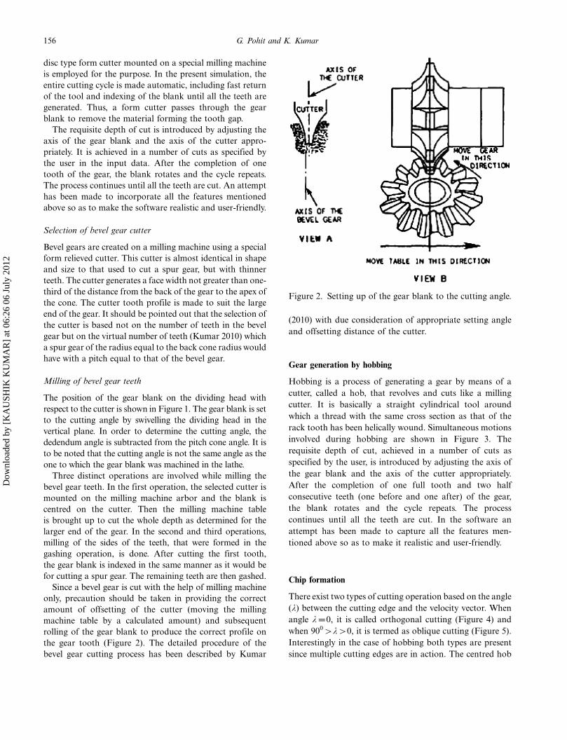
Since a bevel gear is cut with the help of milling machine
only, precaution should be taken in providing the correct
amount of offsetting of the cutter (moving the milling
machine table by a calculated amount) and subsequent
rolling of the gear blank to produce the correct profile on
the gear tooth (Figure 2). The detailed procedure of the
bevel gear cutting process has been described by Kumar
(2010) with due consideration of appropriate setting angle
and offsetting distance of the cutter.
Gear generation by hobbing
Hobbing is a process of generating a gear by means of a
cutter, called a hob, that revolves and cuts like a milling
cutter. It is basically a straight cylindrical tool around
which a thread with the same cross section as that of the
rack tooth has been helically wound. Simultaneous motions
involved during hobbing are shown in Figure 3. The
requisite depth of cut, achieved in a number of cuts as
specified by the user, is introduced by adjusting the axis of
the gear blank and the axis of the cutter appropriately.
After the completion of one full tooth and two half
consecutive teeth (one before and one after) of the gear,
the blank rotates and the cycle repeats. The process
continues until all the teeth are cut. In the software an
attempt has been made to capture all the features men-
tioned above so as to make it realistic and user-friendly.
Chip formation
There exist two types of cutting operation based on the angle
(l) between the cutting edge and the velocity vector. When
angle l�0, it is called orthogonal cutting (Figure 4) and
when 900�l�0, it is termed as oblique cutting (Figure 5).
Interestingly in the case of hobbing both types are present
since multiple cutting edges are in action. The centred hob
Figure 2. Setting up of the gear blank to the cutting angle.
156 G. Pohit and K. Kumar
Dow
nloa
ded
by [
KA
USH
IK K
UM
AR
] at
06:
26 0
6 Ju
ly 2
012
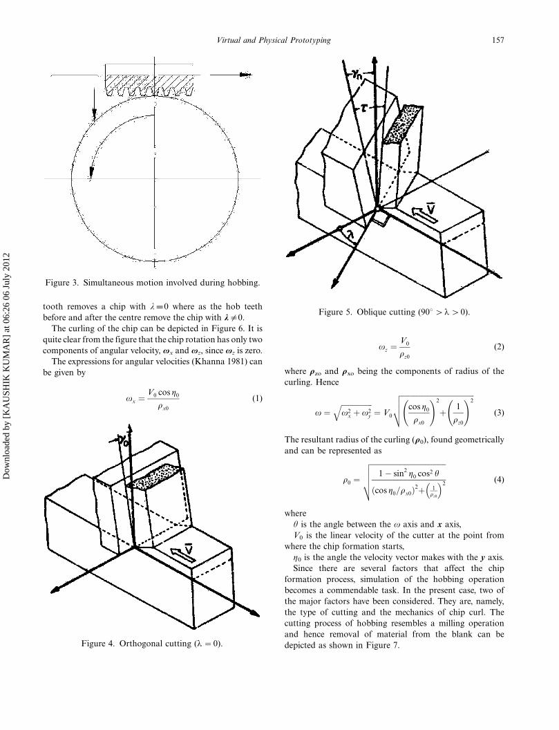
tooth removes a chip with l�0 where as the hob teeth
before and after the centre remove the chip with l"0.
The curling of the chip can be depicted in Figure 6. It is
quite clear from the figure that the chip rotation has only two
components of angular velocity, vx and vz, since vz is zero.
The expressions for angular velocities (Khanna 1981) can
be given by
xx ¼ V0 cos g0
qx0
(1)
xz ¼V0
qz0
(2)
where rzo and rxo being the components of radius of the
curling. Hence
x ¼ffiffiffiffiffiffiffiffiffiffiffiffiffiffiffiffiffix2
x þ x2y
q¼ V0
ffiffiffiffiffiffiffiffiffiffiffiffiffiffiffiffiffiffiffiffiffiffiffiffiffiffiffiffiffiffiffiffiffiffiffiffiffiffiffifficos g0
qx0
!2
þ 1
qz0
!2vuut (3)
The resultant radius of the curling (r0), found geometrically
and can be represented as
q0 ¼
ffiffiffiffiffiffiffiffiffiffiffiffiffiffiffiffiffiffiffiffiffiffiffiffiffiffiffiffiffiffiffiffiffiffiffiffiffiffiffiffiffi1 � sin2 g0 cos2 h
cos g0=qx0ð Þ2þ 1qz0
� 2
vuuut (4)
where
u is the angle between the v axis and x axis,
V0 is the linear velocity of the cutter at the point from
where the chip formation starts,
h0 is the angle the velocity vector makes with the y axis.
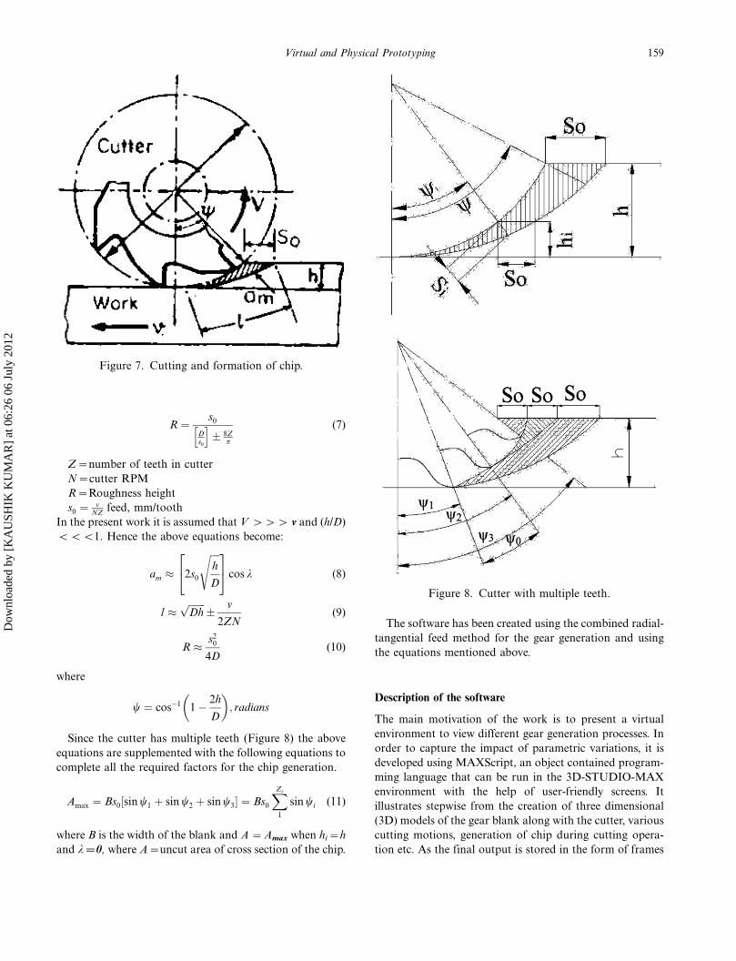
Since there are several factors that affect the chip
formation process, simulation of the hobbing operation
becomes a commendable task. In the present case, two of
the major factors have been considered. They are, namely,
the type of cutting and the mechanics of chip curl. The
cutting process of hobbing resembles a milling operation
and hence removal of material from the blank can be
depicted as shown in Figure 7.Figure 4. Orthogonal cutting (l�0).
Figure 5. Oblique cutting (908�l�0).
Figure 3. Simultaneous motion involved during hobbing.
157Virtual and Physical Prototyping
Dow
nloa
ded
by [
KA
USH
IK K
UM
AR
] at
06:
26 0
6 Ju
ly 2
012
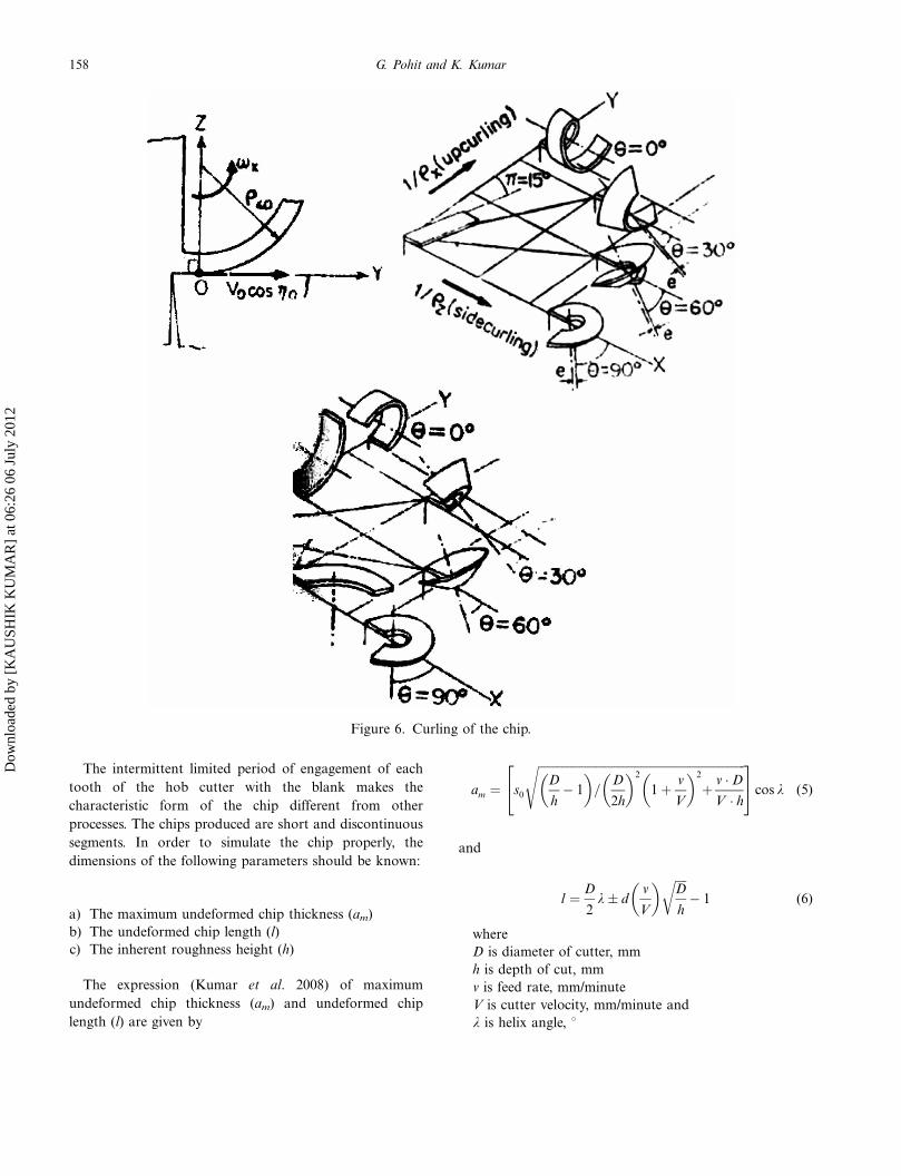
The intermittent limited period of engagement of each
tooth of the hob cutter with the blank makes the
characteristic form of the chip different from other
processes. The chips produced are short and discontinuous
segments. In order to simulate the chip properly, the
dimensions of the following parameters should be known:
a) The maximum undeformed chip thickness (am)
b) The undeformed chip length (l)
c) The inherent roughness height (h)
The expression (Kumar et al. 2008) of maximum
undeformed chip thickness (am) and undeformed chip
length (l) are given by
am ¼ s0
ffiffiffiffiffiffiffiffiffiffiffiffiffiffiffiffiffiffiffiffiffiffiffiffiffiffiffiffiffiffiffiffiffiffiffiffiffiffiffiffiffiffiffiffiffiffiffiffiffiffiffiffiffiffiffiffiffiffiffiffiffiffiffiffiffiffiffiffiffiffiffiD
h� 1
�=
D
2h
�2
1 þ v
V
�2
þ v � D
V � h
s24
35 cos k (5)
and
l ¼ D
2k � d
v
V
� ffiffiffiffiD
h
r� 1 (6)
where
D is diameter of cutter, mm
h is depth of cut, mm
v is feed rate, mm/minute
V is cutter velocity, mm/minute and
l is helix angle, 8
Figure 6. Curling of the chip.
158 G. Pohit and K. Kumar
Dow
nloa
ded
by [
KA
USH
IK K
UM
AR
] at
06:
26 0
6 Ju
ly 2
012
R ¼ s0
Ds0
h i� 8Z
p
(7)
Z�number of teeth in cutter
N�cutter RPM
R�Roughness height
s0 ¼ vNZ
feed, mm/tooth
In the present work it is assumed that V ��� v and (h/D)
BBB1. Hence the above equations become:
am � 2s0
ffiffiffiffih
D
s24
35 cos k (8)
l �ffiffiffiffiffiffiffiDh
p� v
2ZN(9)
R � s20
4D(10)
where
w ¼ cos�1 1 � 2h
D
�; radians
Since the cutter has multiple teeth (Figure 8) the above
equations are supplemented with the following equations to
complete all the required factors for the chip generation.
Amax ¼ Bs0 sin w1 þ sin w2 þ sin w3½ � ¼ Bs0
XZi
1
sin wi (11)
where B is the width of the blank and A �Amax when hi�h
and l�0, where A�uncut area of cross section of the chip.
The software has been created using the combined radial-
tangential feed method for the gear generation and using
the equations mentioned above.
Description of the software
The main motivation of the work is to present a virtual
environment to view different gear generation processes. In
order to capture the impact of parametric variations, it is
developed using MAXScript, an object contained program-
ming language that can be run in the 3D-STUDIO-MAX
environment with the help of user-friendly screens. It
illustrates stepwise from the creation of three dimensional
(3D) models of the gear blank along with the cutter, various
cutting motions, generation of chip during cutting opera-
tion etc. As the final output is stored in the form of frames
Figure 7. Cutting and formation of chip.
Figure 8. Cutter with multiple teeth.
159Virtual and Physical Prototyping
Dow
nloa
ded
by [
KA
USH
IK K
UM
AR
] at
06:
26 0
6 Ju
ly 2
012
or a movie clip, the user not only visualises the gradual
forming of the gear tooth but also gets a realistic view of the
actual machining including chip formation.
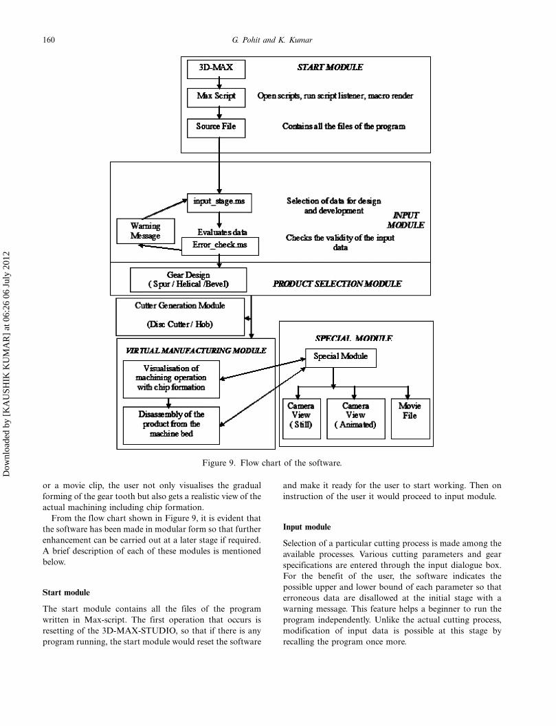
From the flow chart shown in Figure 9, it is evident that
the software has been made in modular form so that further
enhancement can be carried out at a later stage if required.
A brief description of each of these modules is mentioned
below.
Start module
The start module contains all the files of the program
written in Max-script. The first operation that occurs is
resetting of the 3D-MAX-STUDIO, so that if there is any
program running, the start module would reset the software
and make it ready for the user to start working. Then on
instruction of the user it would proceed to input module.
Input module
Selection of a particular cutting process is made among the
available processes. Various cutting parameters and gear
specifications are entered through the input dialogue box.
For the benefit of the user, the software indicates the
possible upper and lower bound of each parameter so that
erroneous data are disallowed at the initial stage with a
warning message. This feature helps a beginner to run the
program independently. Unlike the actual cutting process,
modification of input data is possible at this stage by
recalling the program once more.
Figure 9. Flow chart of the software.
160 G. Pohit and K. Kumar
Dow
nloa
ded
by [
KA
USH
IK K
UM
AR
] at
06:
26 0
6 Ju
ly 2
012
Cutter generation module
Even before proceeding to simulate the cutting process,
there is a need to create the cutter first by means of which
the subsequent cutting operation of the gear blank can be
depicted by the software. Depending on the type of cutting
process, the corresponding cutter is developed as outlined in
the previous section.
Generation of disc type form milling cutter
In the case of the disc type form cutter, the cutter profile
follows a path as per the equations given below:
x ¼ �r� sin hð Þ; y ¼ r� cos hð Þ � Rd (12)
The value of u is obtained from the user defined
values of number of teeth, module and the pressure
angle of the gear to be produced; r and Rd being the
radii of curvature of the tooth profile and dedendum
circle respectively.
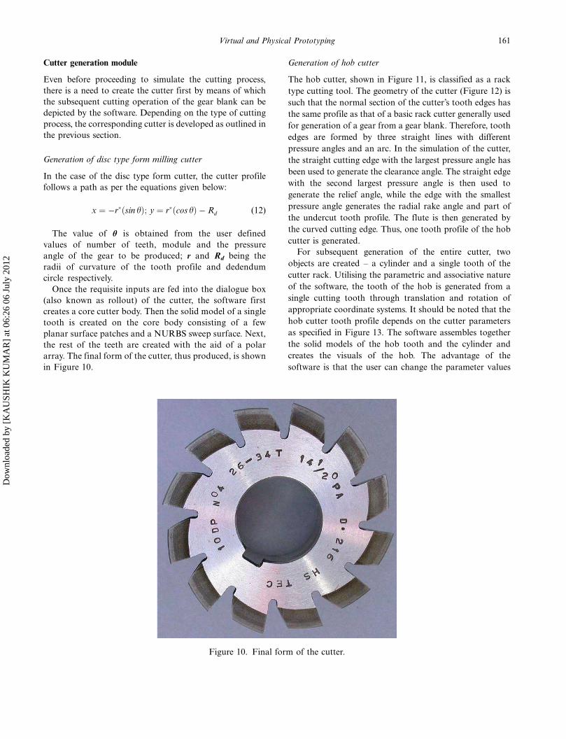
Once the requisite inputs are fed into the dialogue box
(also known as rollout) of the cutter, the software first
creates a core cutter body. Then the solid model of a single
tooth is created on the core body consisting of a few
planar surface patches and a NURBS sweep surface. Next,
the rest of the teeth are created with the aid of a polar
array. The final form of the cutter, thus produced, is shown
in Figure 10.
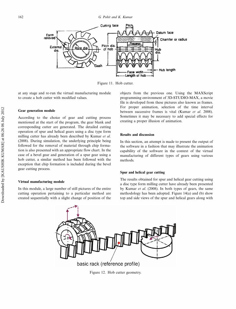
Generation of hob cutter
The hob cutter, shown in Figure 11, is classified as a rack
type cutting tool. The geometry of the cutter (Figure 12) is
such that the normal section of the cutter’s tooth edges has
the same profile as that of a basic rack cutter generally used
for generation of a gear from a gear blank. Therefore, tooth
edges are formed by three straight lines with different
pressure angles and an arc. In the simulation of the cutter,
the straight cutting edge with the largest pressure angle has
been used to generate the clearance angle. The straight edge
with the second largest pressure angle is then used to
generate the relief angle, while the edge with the smallest
pressure angle generates the radial rake angle and part of
the undercut tooth profile. The flute is then generated by
the curved cutting edge. Thus, one tooth profile of the hob
cutter is generated.
For subsequent generation of the entire cutter, two
objects are created � a cylinder and a single tooth of the
cutter rack. Utilising the parametric and associative nature
of the software, the tooth of the hob is generated from a
single cutting tooth through translation and rotation of
appropriate coordinate systems. It should be noted that the
hob cutter tooth profile depends on the cutter parameters
as specified in Figure 13. The software assembles together
the solid models of the hob tooth and the cylinder and
creates the visuals of the hob. The advantage of the
software is that the user can change the parameter values
Figure 10. Final form of the cutter.
161Virtual and Physical Prototyping
Dow
nloa
ded
by [
KA
USH
IK K
UM
AR
] at
06:
26 0
6 Ju
ly 2
012
at any stage and re-run the virtual manufacturing module
to create a hob cutter with modified values.
Gear generation module
According to the choice of gear and cutting process
mentioned at the start of the program, the gear blank and
corresponding cutter are generated. The detailed cutting
operation of spur and helical gears using a disc type form
milling cutter has already been described by Kumar et al.
(2008). During simulation, the underlying principle being
followed for the removal of material through chip forma-
tion is also presented with an appropriate flow chart. In the
case of a bevel gear and generation of a spur gear using a
hob cutter, a similar method has been followed with the
exception that chip formation is included during the bevel
gear cutting process.
Virtual manufacturing module
In this module, a large number of still pictures of the entire
cutting operation pertaining to a particular method are
created sequentially with a slight change of position of the
objects from the previous one. Using the MAXScript
programming environment of 3D-STUDIO-MAX, a movie
file is developed from these pictures also known as frames.
For proper animation, selection of the time interval
between successive frames is vital (Kumar et al. 2008).
Sometimes it may be necessary to add special effects for
creating a proper illusion of animation.
Results and discussion
In this section, an attempt is made to present the output of
the software in a fashion that may illustrate the animation
capability of the software in the context of the virtual
manufacturing of different types of gears using various
methods.
Spur and helical gear cutting
The results obtained for spur and helical gear cutting using
a disc type form milling cutter have already been presented
by Kumar et al. (2008). In both types of gears, the same
methodology has been adopted. Figure 14(a) and (b) show
top and side views of the spur and helical gears along with
Figure 11. Hob cutter.
Figure 12. Hob cutter geometry.
162 G. Pohit and K. Kumar
Dow
nloa
ded
by [
KA
USH
IK K
UM
AR
] at
06:
26 0
6 Ju
ly 2
012
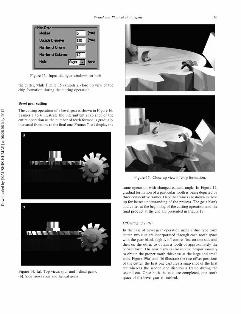
the cutter, while Figure 15 exhibits a close up view of the
chip formation during the cutting operation.
Bevel gear cutting
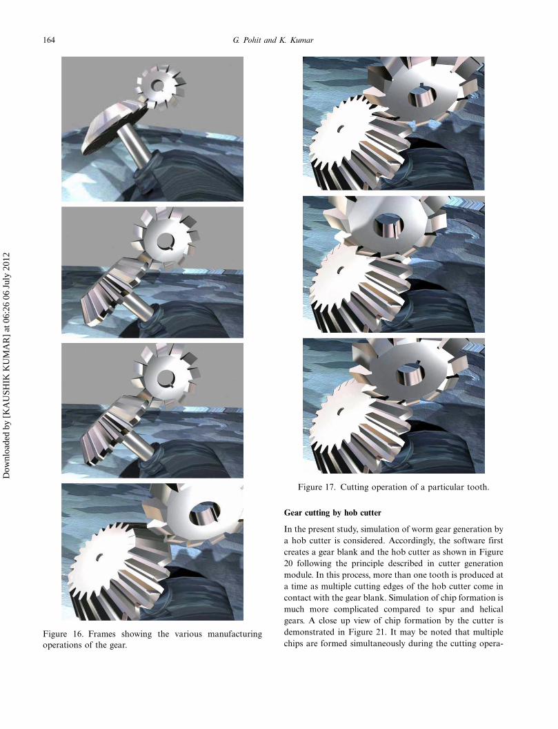
The cutting operation of a bevel gear is shown in Figure 16.
Frames 1 to 6 illustrate the intermittent snap shot of the
entire operation as the number of teeth formed is gradually
increased from one to the final one. Frames 7 to 9 display the
same operation with changed camera angle. In Figure 17,
gradual formation of a particular tooth is being depicted by
three consecutive frames. Here the frames are shown in close
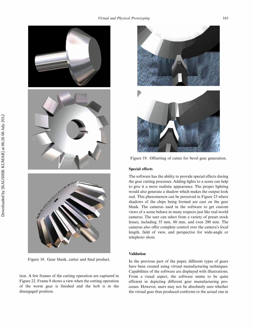
up for better understanding of the process. The gear blank
and cutter at the beginning of the cutting operation and the
final product at the end are presented in Figure 18.
Offsetting of cutter
In the case of bevel gear operation using a disc type form
cutter, two cuts are incorporated through each tooth space
with the gear blank slightly off centre, first on one side and
then on the other, to obtain a tooth of approximately the
correct form. The gear blank is also rotated proportionately
to obtain the proper tooth thickness at the large and small
ends. Figure 19(a) and (b) illustrate the two offset positions
of the cutter, the first one captures a snap shot of the first
cut whereas the second one displays a frame during the
second cut. Once both the cuts are completed, one tooth
space of the bevel gear is finished.
Figure 13. Input dialogue windows for hob.
Figure 14. (a). Top views spur and helical gears.
(b). Side views spur and helical gears.
Figure 15. Close up view of chip formation.
163Virtual and Physical Prototyping
Dow
nloa
ded
by [
KA
USH
IK K
UM
AR
] at
06:
26 0
6 Ju
ly 2
012
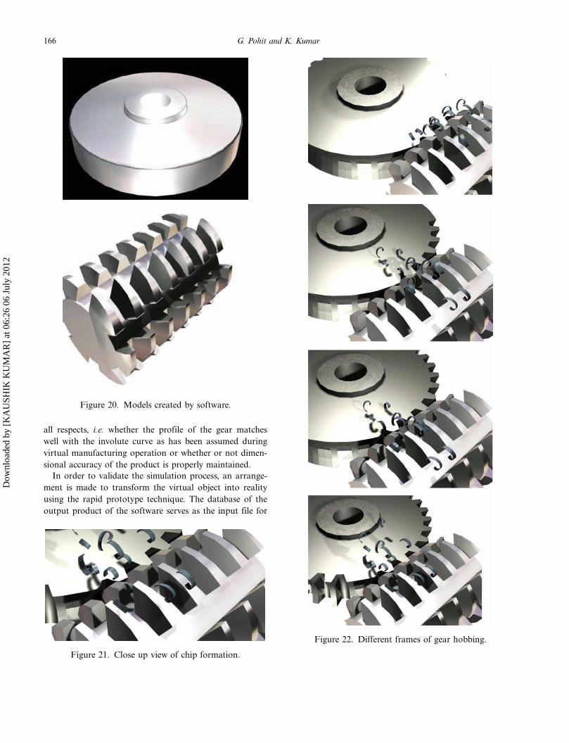
Gear cutting by hob cutter
In the present study, simulation of worm gear generation by
a hob cutter is considered. Accordingly, the software first
creates a gear blank and the hob cutter as shown in Figure
20 following the principle described in cutter generation
module. In this process, more than one tooth is produced at
a time as multiple cutting edges of the hob cutter come in
contact with the gear blank. Simulation of chip formation is
much more complicated compared to spur and helical
gears. A close up view of chip formation by the cutter is
demonstrated in Figure 21. It may be noted that multiple
chips are formed simultaneously during the cutting opera-Figure 16. Frames showing the various manufacturing
operations of the gear.
Figure 17. Cutting operation of a particular tooth.
164 G. Pohit and K. Kumar
Dow
nloa
ded
by [
KA
USH
IK K
UM
AR
] at
06:
26 0
6 Ju
ly 2
012
tion. A few frames of the cutting operation are captured in
Figure 22. Frame 8 shows a view when the cutting operation
of the worm gear is finished and the hob is in the
disengaged position.
Special effects
The software has the ability to provide special effects during
the gear cutting processes. Adding lights to a scene can help
to give it a more realistic appearance. The proper lighting
would also generate a shadow which makes the output look
real. This phenomenon can be perceived in Figure 23 where
shadows of the chips being formed are cast on the gear
blank. The cameras used in the software to get custom
views of a scene behave in many respects just like real-world
cameras. The user can select from a variety of preset stock
lenses, including 35 mm, 80 mm, and even 200 mm. The
cameras also offer complete control over the camera’s focal
length, field of view, and perspective for wide-angle or
telephoto shots.
Validation
In the previous part of the paper, different types of gears
have been created using virtual manufacturing techniques.
Capabilities of the software are displayed with illustrations.
From a visual aspect, the software seems to be quite
efficient in depicting different gear manufacturing pro-
cesses. However, users may not be absolutely sure whether
the virtual gear thus produced conforms to the actual one in
Figure 18. Gear blank, cutter and final product.
Figure 19. Offsetting of cutter for bevel gear generation.
165Virtual and Physical Prototyping
Dow
nloa
ded
by [
KA
USH
IK K
UM
AR
] at
06:
26 0
6 Ju
ly 2
012
all respects, i.e. whether the profile of the gear matches
well with the involute curve as has been assumed during
virtual manufacturing operation or whether or not dimen-
sional accuracy of the product is properly maintained.
In order to validate the simulation process, an arrange-
ment is made to transform the virtual object into reality
using the rapid prototype technique. The database of the
output product of the software serves as the input file for
Figure 20. Models created by software.
Figure 21. Close up view of chip formation.
Figure 22. Different frames of gear hobbing.
166 G. Pohit and K. Kumar
Dow
nloa
ded
by [
KA
USH
IK K
UM
AR
] at
06:
26 0
6 Ju
ly 2
012
the RP machine and plastic gears are manufactured. The
dimensions of these actual solid models are then compared
with the virtual gears. Various rapid prototyping (RP)
processes have been developed and used in the past decade.
Primary criteria for the selection of the RP technique is
based on the fact that built gears will have the optimum
combination of strength, dimensional accuracy and surface
finish. It has been ascertained that Fused Deposition
Modelling (FDM) is most suited for the present case
(Kumar 2010).
The detail of the validation procedure is mentioned in the
next section.
Exporting virtually manufactured product to the FDM
machine
Figure 24 represents the steps being followed for conversion
of the virtual products into real objects using the FDM
machine. Proper transfer of data from the CAD domain to
the RP system is a crucial part.
In the present case, the models are created in the 3D-
STUDIO-MAX environment which is also a standard CAD
software. The output of the software creates models devel-
oped in a 3D environment with ‘max’ extension. This is then
converted as a ‘stl’ extension. It should be emphasised that
in order to retain the shape and other design properties, the
model must be saved with proper mesh density; the higher
the density, the lower the mesh size will be, however
preparation time would be more. The model contour
becomes deformed in the case of a lower mesh density.
Processing in FDM
Once the input parameters, say layer thickness, orientation,
model fill and support type are fixed, the model is packed
and the layers with support are first visualised even before
Figure 23. Effects of light and shadow to the output.
Figure 24. Data transfer between the CAD and the RP
system.
Table 1. A comparative study between the virtual manufac-tured gears and the RP gears.
Sl. No. Parameters
Ideal
values
Average values of gears
manufactured using FDM
SPUR GEAR No. of teeth 24 24
Outside diameter
(mm)
97.6 97.65
Root diameter (mm) 81.32 81.39
Inside diameter
(mm)
22.27 22.25
Tooth thickness
(mm)
8 8.34
HELICAL
GEAR
No. of teeth 24 24
Outside diameter
(mm)
97.91 97.94
Root diameter (mm) 81.66 81.69
Inside diameter
(mm)
22.2 22.23
Tooth thickness
(mm)
8 8.2
BEVEL
GEAR
No. of teeth 24 24
Taper angle 520 510 45?Major diameter
(mm)
73 72.95
Root diameter at
bigger end (mm)
60 60.20
Root diameter at
smaller end (mm)
42 42.30
Tooth thickness
(mm)
18.75 18.76
Figure 25. Spur gear developed using FDM.
167Virtual and Physical Prototyping
Dow
nloa
ded
by [
KA
USH
IK K
UM
AR
] at
06:
26 0
6 Ju
ly 2
012
actual ‘printing’. After being satisfied with the structure and
the individual layers, instruction may be given for final
‘printing’. The product with the support is then placed in an
ultrasonic tank (accessory of the machine) fitted with a
heater and the soluble support system dissolves leaving
behind the model in its final form.
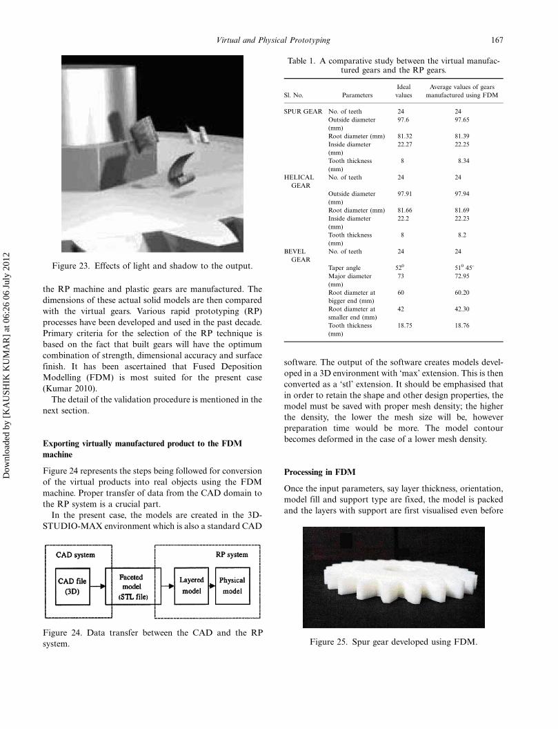
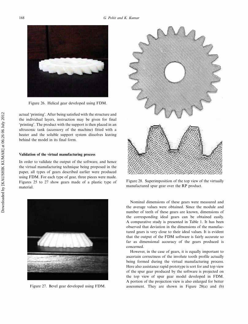
Validation of the virtual manufacturing process
In order to validate the output of the software, and hence
the virtual manufacturing technique being proposed in the
paper, all types of gears described earlier were produced
using FDM. For each type of gear, three pieces were made.
Figures 25 to 27 show gears made of a plastic type of
material.
Nominal dimensions of these gears were measured and
the average values were obtained. Since the module and
number of teeth of these gears are known, dimensions of
the corresponding ideal gears can be obtained easily.
A comparative study is presented in Table 1. It has been
observed that deviation in the dimensions of the manufac-
tured gears is very close to their ideal values. It is evident
that the output of the FDM software is fairly accurate so
far as dimensional accuracy of the gears produced is
concerned.
However, in the case of gears, it is equally important to
ascertain correctness of the involute tooth profile actually
being formed during the virtual manufacturing process.
Here also assistance rapid prototype is sort for and top view
of the spur gear produced by the software is projected on
the top view of spur gear model developed in FDM.
A portion of the projection view is also enlarged for better
assessment. They are shown in Figure 28(a) and (b)
Figure 26. Helical gear developed using FDM.
Figure 27. Bevel gear developed using FDM.
Figure 28. Superimposition of the top view of the virtually
manufactured spur gear over the RP product.
168 G. Pohit and K. Kumar
Dow
nloa
ded
by [
KA
USH
IK K
UM
AR
] at
06:
26 0
6 Ju
ly 2
012
respectively. The RP gear is visible as a dotted object
whereas the outline of the gear produced by the software is
represented by a black line. From these figures, it is
observed that the output profiles of both systems closely
match with one another.
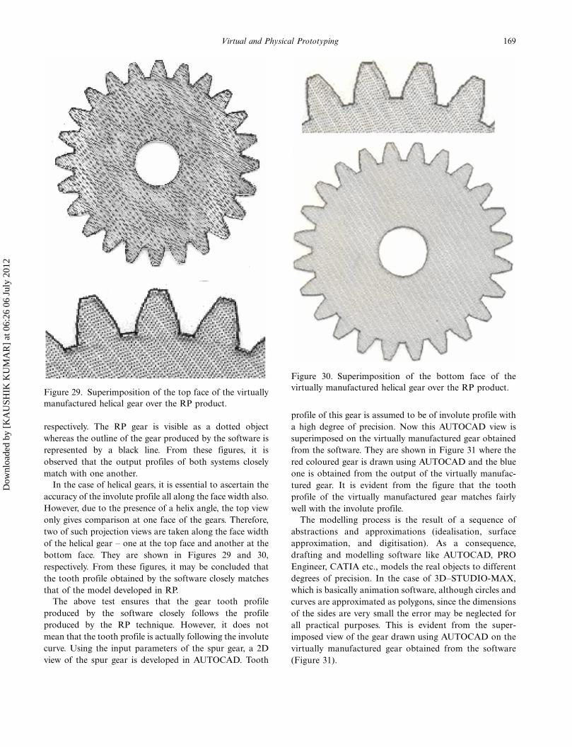
In the case of helical gears, it is essential to ascertain the
accuracy of the involute profile all along the face width also.
However, due to the presence of a helix angle, the top view
only gives comparison at one face of the gears. Therefore,
two of such projection views are taken along the face width
of the helical gear � one at the top face and another at the
bottom face. They are shown in Figures 29 and 30,
respectively. From these figures, it may be concluded that
the tooth profile obtained by the software closely matches
that of the model developed in RP.
The above test ensures that the gear tooth profile
produced by the software closely follows the profile
produced by the RP technique. However, it does not
mean that the tooth profile is actually following the involute
curve. Using the input parameters of the spur gear, a 2D
view of the spur gear is developed in AUTOCAD. Tooth
profile of this gear is assumed to be of involute profile with
a high degree of precision. Now this AUTOCAD view is
superimposed on the virtually manufactured gear obtained
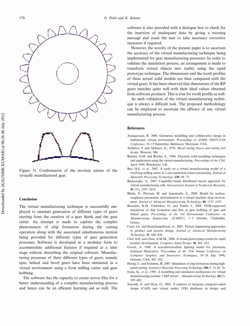
from the software. They are shown in Figure 31 where the
red coloured gear is drawn using AUTOCAD and the blue
one is obtained from the output of the virtually manufac-
tured gear. It is evident from the figure that the tooth
profile of the virtually manufactured gear matches fairly
well with the involute profile.
The modelling process is the result of a sequence of
abstractions and approximations (idealisation, surface
approximation, and digitisation). As a consequence,
drafting and modelling software like AUTOCAD, PRO
Engineer, CATIA etc., models the real objects to different
degrees of precision. In the case of 3D�STUDIO-MAX,
which is basically animation software, although circles and
curves are approximated as polygons, since the dimensions
of the sides are very small the error may be neglected for
all practical purposes. This is evident from the super-
imposed view of the gear drawn using AUTOCAD on the
virtually manufactured gear obtained from the software
(Figure 31).
Figure 29. Superimposition of the top face of the virtually
manufactured helical gear over the RP product.
Figure 30. Superimposition of the bottom face of the
virtually manufactured helical gear over the RP product.
169Virtual and Physical Prototyping
Dow
nloa
ded
by [
KA
USH
IK K
UM
AR
] at
06:
26 0
6 Ju
ly 2
012
Conclusion
The virtual manufacturing technique is successfully em-
ployed to simulate generation of different types of gears
starting from the creation of a gear blank and the gear
cutter. An attempt is made to capture the complex
phenomenon of chip formation during the cutting
operation along with the associated simultaneous motion
being provided for different types of gear generation
processes. Software is developed in a modular form to
accommodate additional features if required at a later
stage without disturbing the original software. Manufac-
turing processes of three different types of gears, namely
spur, helical and bevel gears have been simulated in a
virtual environment using a form milling cutter and gear
hobbing.
The software has the capacity to create movie files for a
better understanding of a complex manufacturing process
and hence can be an efficient learning aid as well. The
software is also provided with a dialogue box to check for
the insertion of inadequate data by giving a warning
message and assist the user to take necessary corrective
measures if required.
However, the novelty of the present paper is to ascertain
the accuracy of the virtual manufacturing technique being
implemented for gear manufacturing processes. In order to
validate the simulation process, an arrangement is made to
transform virtual objects into reality using the rapid
prototype technique. The dimensions and the tooth profiles
of these actual solid models are then compared with the
virtual gears. It has been observed that dimensions of the RP
gears matches quite well with their ideal values obtained
from software products. This is true for tooth profile as well.
As such validation of the virtual manufacturing techni-
que is always a difficult task. The proposed methodology
can be employed to ascertain the efficacy of any virtual
manufacturing process.
References
Arangarasan, R. 2000. Geometric modelling and collaborative design in
multimodel, virtual environment. Proceedings of ASME, IDETC/CIE
Conference, 10�13 September, Baltimore, Maryland, USA.
Arshinov, V. and Alekseev, G., 1976. Metal cutting theory and cutting tool
design. Moscow: Mir.
Balyliss, G.M. and Bowler, A., 1994. Theoretic solid modeling techniques
and application using the virtual manufacturing. Proceedings of the CSG.
April 1994, Winchester, UK.
Bao, Q.S., et al., 2002. A study on a virtual manufacturing model of a
revolving milling cutter in 2-axis numerical control processing. Journal of
Materials Processing Technology, 120, 68�75.
Baykasoglu, A., 2003. Capability-based distributed layout approach for
virtual manufacturing cells. International Journal of Production Research,
41 (11), 2597�2618.
Bilalis, N., Petousis, M. and Antoniadis, A., 2009. Model for surface-
roughness parameters determination in a virtual machine shop environ-
ment. Journal of Advanced Manufacturing Technology, 40, 1137�1147.
Bouzakis, K.D., Friderikos, O., and Tsiafis, I., 2008. FEM-supported
simulation of chip formation and flow in gear hobbing of spur and
helical gears. Proceedings of the 3rd International Conference on
Manufacturing Engineering (ICMEN), 1�3 October, Chalkidiki,
Greece.
Cecil, J.A. and Kanchanapiboon, A., 2007. Virtual engineering approaches
in product and process design. Journal of Advanced Manufacturing
Technology, 31, 846�856.
Choi, S.H. and Chan, A.M.M., 2004. A virtual prototyping system for rapid
product development. Computer-Aided Design, 36, 401�412.
Gooch, A. 1998. A non-photorealistic lighting model for automatic
technical illustration. Proceedings of the 25th Annual Conference on
Computer Graphics and Interactive Techniques, 19�24 July 1998,
Orlando, USA, 447�452.
Hortig, C. and Svendsen, B., 2007. Simulation of chip formation during high-
speed cutting. Journal of Materials Processing Technology, 186 (1�3), 66�76.
Iwata, K., et al., 1995. A modelling and simulation architecture for virtual
manufacturing systems. CIRPAnnals � Manufacturing Technology, 44 (1),
399�402.
Jezernik, A. and Hren, G., 2003. A solution to integrate computer-aided
design (CAD) and virtual reality (VR) databases in design and
Figure 31. Confirmation of the involute nature of the
virtually manufactured gear.
170 G. Pohit and K. Kumar
Dow
nloa
ded
by [
KA
USH
IK K
UM
AR
] at
06:
26 0
6 Ju
ly 2
012
manufacturing processes. The International Journal of Advanced Manu-
facturing Technology, 22 (11�12), 768�774.
Khanna, R., ed., 1981. Production technology. New Delhi: Tata McGraw-Hill.
Kimera, F., 1993. Product and process modelling as a kernel for virtual
manufacturing environment. CIRP Annals � Manufacturing Technology,
42 (1), 147�150.
Kumar, K., 2010. Application of virtual manufacturing technique to various
gear generation methods and its validation using rapid prototyping technique.
Thesis (PhD). Dept. of Mechanical Engineering, Jadavpur University.
Kumar, K., Mukherjee, S.K. and Pohit, G., 2007a. Virtual manufacturing of
helical gears with chip formation. Proceedings of ECHDEM, 28�30
November 2007, Satyabhama University, Chennai, India. 98�103.
Kumar, K., Mukherjee, S.K. and Pohit, G., 2007b. Virtual manufacturing of
spur gears with chip formation. Proceedings of International Conference
on Advanced Manufacturing Technology (ICAMT 2007), 29�30
November 2007, CMERI, Durgapur, India. 346�353.
Kumar, K., Mukherjee, S.K. and Pohit, G., 2008. Virtual manufacturing of
gears with chip formation. International Journal of Computer Applications
in Technology, 33 (1), 63�71.
Luo, L., et al., 2010. Research on behavior simulation of multi-axis CNC
machine tool in virtual environment. International Conference on
Measuring Technology and Mechatronics Automation, 13�14 March,
Changsha, China.
Okushima, K. and Minato, K., 1959. On the behavior of chip in steel
cutting. Bulletin of the Japan Society of Mechanical Engineers, 2 (5),
58�64.
Pattanayak, R.K., Pohit, G. and Saha, K.N., 2003. Application of solid
modelling in virtual manufacturing of spur gear. Proceedings of 11th
National Conference on Machines and Mechanism (Nacomm), December
2003, I.I.T. Delhi, Delhi, India. 683�688.
Pohit, G., 2006. Application of virtual manufacturing in generation of
gears. International Journal of Advanced Manufacturing Technology, 31
(1�2), 85�91.
Pradhan, S.S. and Huang, W.V., 1998. Virtual manufacturing information
system using Java and JDBC. Computers & Industrial Engineering, 35
(1�2), 255�258.
Roy, S., Pohit, G. and Saha, K.N., 2003. Computer aided design of spur
gear. Proceedings of 20th AIMTDR Conference, 13�15 December 2002,
BIT Mesra, Ranchi India.
Taylor, R., 1994. Virtual factory. International Journal of Shape Modeling,
2 (4), 215�226.
Tesic, R. and Banerjee, P., 1999. Design of virtual objects for exact collision
detection in virtual reality modeling of manufacturing processes.
Proceedings of International Conference on Robotics and Automation,
10�15 May 1999, Detroit, USA.
Willis, P., 1993. Virtual manufacturing. Proceedings of International
Workshop on Graphics and Robotics, Schloss Dagstuhl, Germany,
189�197.
Yao, Y., et al., 2006. Modeling of virtual workpiece with machining errors
representation in turning. Journal of Materials Processing Technology,
172, 437�444.
Young, H.T., Mathew, P. and Oxley, P.L.B., 1987. Allowing for nose radius
effects in predicting the chip flow direction and cutting forces in bar
turning. Proceedings of the Institution of Mechanical Engineers, Part C:
Mechanical Engineering Science, 201 (C3), 213�226.
171Virtual and Physical Prototyping
Dow
nloa
ded
by [
KA
USH
IK K
UM
AR
] at
06:
26 0
6 Ju
ly 2
012


