Embed Size (px)
Citation preview
Siemens AG Building Technologies Division
VRD Series
Technical InstructionsDocument No. 7649
VRD40.xxxUxSeptember 08, 2016
VRD40.xxxUx Double Valves for use with SKP... electro-hydraulic actuators
ISO 9001 and 14001 REGISTERED FIRM
Only with series SKPxx.xxxUx actuators
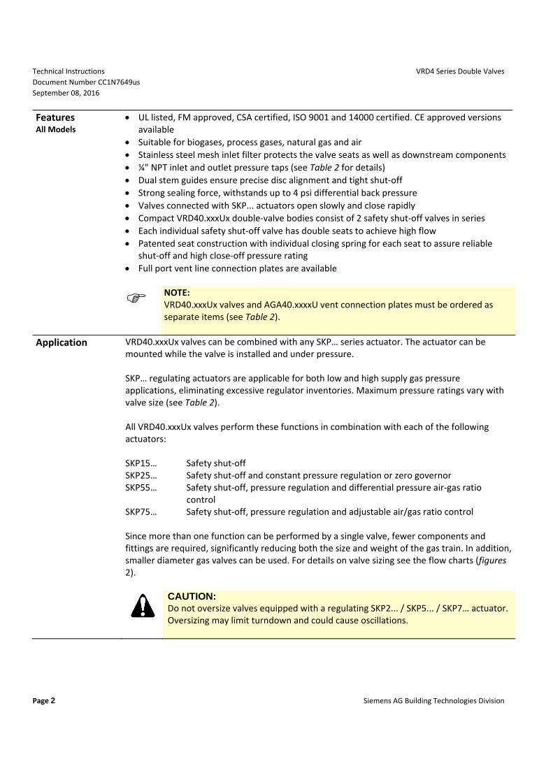
Description The normally closed VRDxx.xxxUx series of modular double-body gas valves combine with SKP… series electro-hydraulic actuators to provide safety shut-off, gas pressure regulation and/or air-gas ratio control for commercial or industrial gas burners.
Table 1. VRDxx.xxxU model numbers Model Numbers Body style Connection
VRD40.040U Double NPT thread VRD40.050U Double NPT thread VRD40.065UF Double ANSI flange VRD40.080UF Double ANSI flange VRD40.100UF Double ANSI flange VRD40.150UF Double ANSI flange
Technical Instructions VRD4 Series Double Valves Document Number CC1N7649us September 08, 2016
Page 2 Siemens AG Building Technologies Division
Features All Models
UL listed, FM approved, CSA certified, ISO 9001 and 14000 certified. CE approved versions available
Suitable for biogases, process gases, natural gas and air Stainless steel mesh inlet filter protects the valve seats as well as downstream components ¼" NPT inlet and outlet pressure taps (see Table 2 for details) Dual stem guides ensure precise disc alignment and tight shut-off Strong sealing force, withstands up to 4 psi differential back pressure Valves connected with SKP... actuators open slowly and close rapidly Compact VRD40.xxxUx double-valve bodies consist of 2 safety shut-off valves in series Each individual safety shut-off valve has double seats to achieve high flow Patented seat construction with individual closing spring for each seat to assure reliable
shut-off and high close-off pressure rating Full port vent line connection plates are available
NOTE: VRD40.xxxUx valves and AGA40.xxxxU vent connection plates must be ordered as separate items (see Table 2).
Application VRD40.xxxUx valves can be combined with any SKP… series actuator. The actuator can be mounted while the valve is installed and under pressure. SKP… regulating actuators are applicable for both low and high supply gas pressure applications, eliminating excessive regulator inventories. Maximum pressure ratings vary with valve size (see Table 2). All VRD40.xxxUx valves perform these functions in combination with each of the following actuators: SKP15… Safety shut-off SKP25… Safety shut-off and constant pressure regulation or zero governor SKP55… Safety shut-off, pressure regulation and differential pressure air-gas ratio
control SKP75… Safety shut-off, pressure regulation and adjustable air/gas ratio control Since more than one function can be performed by a single valve, fewer components and fittings are required, significantly reducing both the size and weight of the gas train. In addition, smaller diameter gas valves can be used. For details on valve sizing see the flow charts (figures 2).
CAUTION: Do not oversize valves equipped with a regulating SKP2... / SKP5... / SKP7… actuator. Oversizing may limit turndown and could cause oscillations.
VRD4 Series Double Valves Technical Instructions Document Number CC1N7649us September 08, 2016
Siemens AG Building Technologies Division Page 3
Ordering information
Gas valves and actuators are ordered separately. For additional SKP… actuator information, see the following technical instructions: SKP15… 155-751P25 SKP25… 155-752P25 SKP55… 155-753P25 SKP75… 155-754P25
NOTE: The SKP... actuators have an operating temperature range of 14 °F to 140 °F (-10 °C to 60 °C)!
Table 2. Product numbers
Product number
Size Maximum operating pressure
psi
Close-off pressure
psi
Capacity CFH
Natural gas at
P=1" W.C.
Number of test points,
1/4" NPT
Valve body material
Inlet Outlet
VRD40.040U 1-1/2" NPT 20 75 1800 1 1 Aluminum VRD40.050U 2" NPT 20 75 2300 1 1 Aluminum
VRD40.065UF 2-1/2" Flanged 10 75 3.880 1 1 Aluminum VRD40.080UF 3" Flanged 10 75 5.370 1 1 Aluminum VRD40.100UF 4" Flanged 10 30 9.680 1 1 Aluminum VRD40.150UF 6" Flanged 10 30 17.490 1 1 Aluminum
Table 3. Accessories Part Number Description Notes
AGA40.4050U 1" NPT vent connection plate Each vent connection includes a ¼" NPT test port, see Mounting instruction M7631.3 (74 319 0278 0)
AGA40.6580U 1 ¼" NPT vent connection plate AGA40.0100U 2" NPT vent connection plate AGA40.0150U 2 ½" NPT vent connection plate
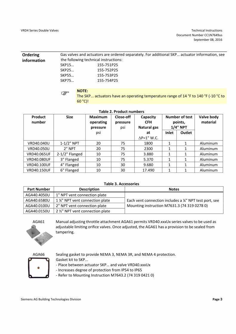
AGA61
Manual adjusting throttle attachment AGA61 permits VRD40.xxxUx series valves to be used as adjustable limiting orifice valves. Once adjusted, the AGA61 has a provision to be sealed from tampering.
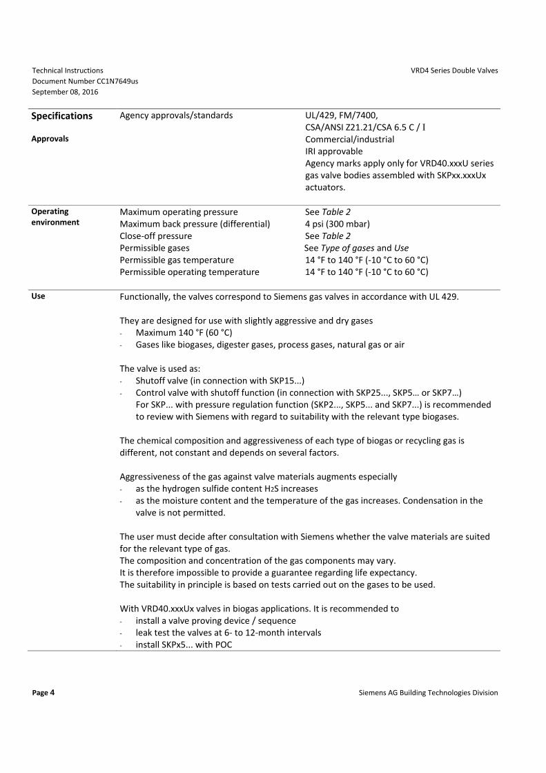
AGA66
Sealing gasket to provide NEMA 3, NEMA 3R, and NEMA 4 protection. Gasket kit to SKP... - Place between actuator SKP… and valve VRD40.xxxUx - Increases degree of protection from IP54 to IP65 - Refer to Mounting Instruction M7643.2 (74 319 0421 0)
Technical Instructions VRD4 Series Double Valves Document Number CC1N7649us September 08, 2016
Page 4 Siemens AG Building Technologies Division
Specifications Approvals
Agency approvals/standards UL/429, FM/7400, CSA/ANSI Z21.21/CSA 6.5 C / I Commercial/industrial IRI approvable Agency marks apply only for VRD40.xxxU series gas valve bodies assembled with SKPxx.xxxUx actuators.
Operating environment
Maximum operating pressure See Table 2 Maximum back pressure (differential) 4 psi (300 mbar) Close-off pressure See Table 2 Permissible gases See Type of gases and Use Permissible gas temperature 14 °F to 140 °F (-10 °C to 60 °C) Permissible operating temperature 14 °F to 140 °F (-10 °C to 60 °C)
Use Functionally, the valves correspond to Siemens gas valves in accordance with UL 429. They are designed for use with slightly aggressive and dry gases - Maximum 140 °F (60 °C) - Gases like biogases, digester gases, process gases, natural gas or air The valve is used as: - Shutoff valve (in connection with SKP15...) - Control valve with shutoff function (in connection with SKP25..., SKP5… or SKP7…)
For SKP... with pressure regulation function (SKP2..., SKP5... and SKP7...) is recommended to review with Siemens with regard to suitability with the relevant type biogases.
The chemical composition and aggressiveness of each type of biogas or recycling gas is different, not constant and depends on several factors. Aggressiveness of the gas against valve materials augments especially - as the hydrogen sulfide content H2S increases - as the moisture content and the temperature of the gas increases. Condensation in the
valve is not permitted. The user must decide after consultation with Siemens whether the valve materials are suited for the relevant type of gas. The composition and concentration of the gas components may vary. It is therefore impossible to provide a guarantee regarding life expectancy. The suitability in principle is based on tests carried out on the gases to be used. With VRD40.xxxUx valves in biogas applications. It is recommended to - install a valve proving device / sequence - leak test the valves at 6- to 12-month intervals - install SKPx5... with POC
VRD4 Series Double Valves Technical Instructions Document Number CC1N7649us September 08, 2016
Siemens AG Building Technologies Division Page 5
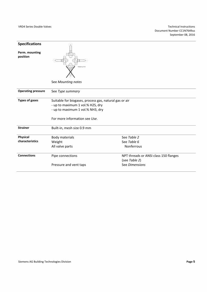
Specifications Perm. mounting position
7649z01us/1215
See Mounting notes
Operating pressure See Type summary
Types of gases Suitable for biogases, process gas, natural gas or air - up to maximum 1 vol.% H2S, dry - up to maximum 1 vol.% NH3, dry For more information see Use.
Strainer Built-in, mesh size 0.9 mm
Physical characteristics
Body materials See Table 2 Weight See Table 6 All valve parts Nonferrous
Connections Pipe connections NPT threads or ANSI class 150 flanges (see Table 2)
Pressure and vent taps See Dimensions

Technical Instructions VRD4 Series Double Valves Document Number CC1N7649us September 08, 2016
Page 6 Siemens AG Building Technologies Division
Operation All VRD40.xxxUx gas valves are normally closed, two-way valves. The valves have a standard, integral, stainless steel mesh filter (0.9 mm) in the inlet to protect the downstream components against contamination. VRD40.xxxUx double valves consist of two valves in series. Each valve has a double seat to achieve high flow (see Figure 1). All valves have ¼-inch NPT ports for pressure test connection. A full size vent connection plate is available as an accessory. See Table 2 and 3 for details on ports and vent connection plates.
7649z02/0514
V1 V2
Figure 1. Sectional view of VRD40.065UF Closing springs: Each double seat uses one pair of springs. The spring forces act separately as closing forces on the individual valve seats.
VRD4 Series Double Valves Technical Instructions Document Number CC1N7649us September 08, 2016
Siemens AG Building Technologies Division Page 7
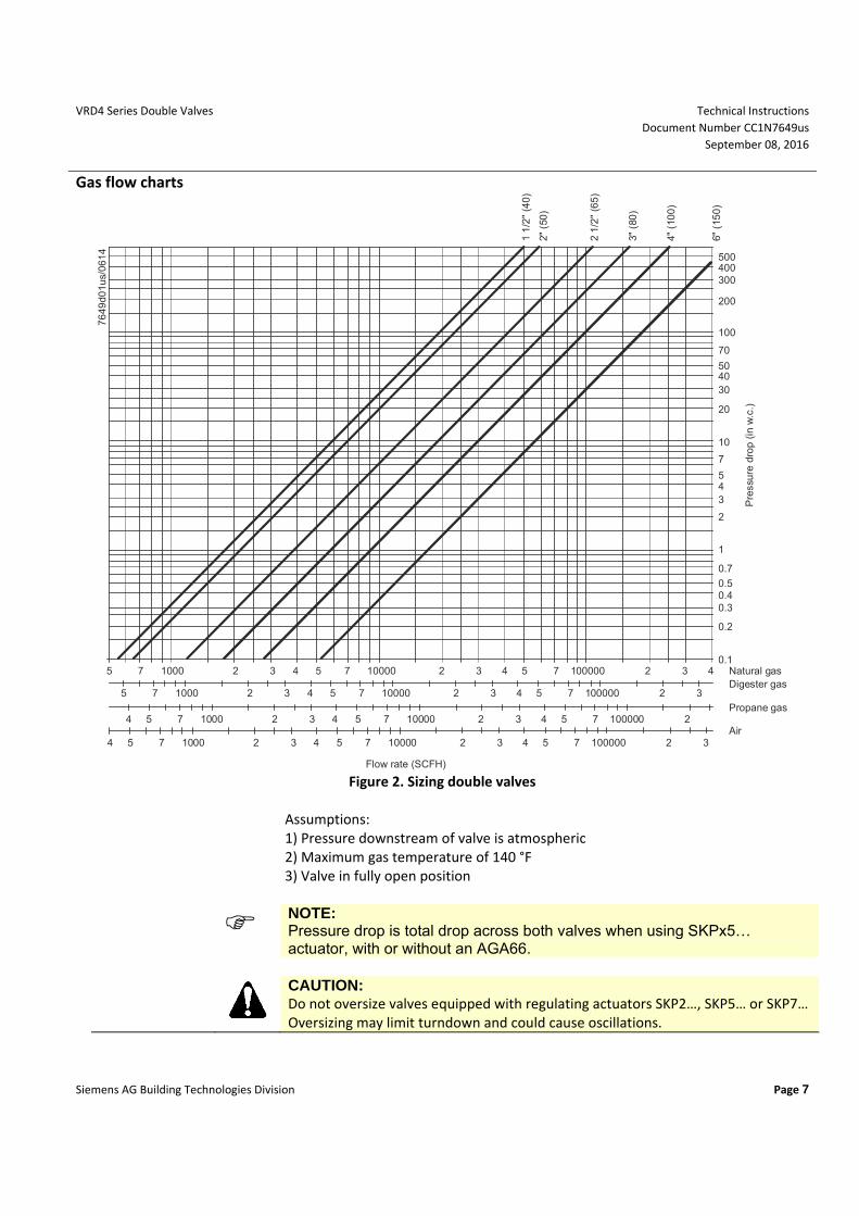
Gas flow charts
1 1
/2"
(40
)
2" (
50)
2 1
/2"
(65
)
3" (
80)
4" (
100
)
6" (
150
)
500400300
200
100
70
504030
20
10
7
543
2
1
0.7
0.50.40.3
0.2
0.1
Pre
ssu
re d
rop
(in
w.c
.)
Natural gasDigester gas
Propane gas
Air
5 7 1000 2 3 4 5 7 10000 2 3 4 5 7 100000 2 3 4
5 7 1000 2 3 4 5 7 10000 2 3 4 5 7 100000 2 3
4 5 7 1000 2 3 4 5 7 10000 2 3 4 5 7 100000 2
4 5 7 1000 2 3 4 5 7 10000 2 3 4 5 7 100000 2 3
Flow rate (SCFH)
76
49d0
1us
/06
14
Figure 2. Sizing double valves
Assumptions: 1) Pressure downstream of valve is atmospheric 2) Maximum gas temperature of 140 °F 3) Valve in fully open position
NOTE: Pressure drop is total drop across both valves when using SKPx5… actuator, with or without an AGA66.
CAUTION: Do not oversize valves equipped with regulating actuators SKP2…, SKP5… or SKP7… Oversizing may limit turndown and could cause oscillations.
Technical Instructions VRD4 Series Double Valves Document Number CC1N7649us September 08, 2016
Page 8 Siemens AG Building Technologies Division
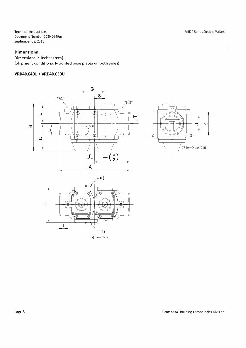
Dimensions Dimensions in Inches (mm) (Shipment conditions: Mounted base plates on both sides) VRD40.040U / VRD40.050U
a)
a)
G
S
F
A
2A
7649m04us/1215
1/4"1/4"
1/4"
a) Base plate
VRD4 Series Double Valves Technical Instructions Document Number CC1N7649us September 08, 2016
Siemens AG Building Technologies Division Page 9
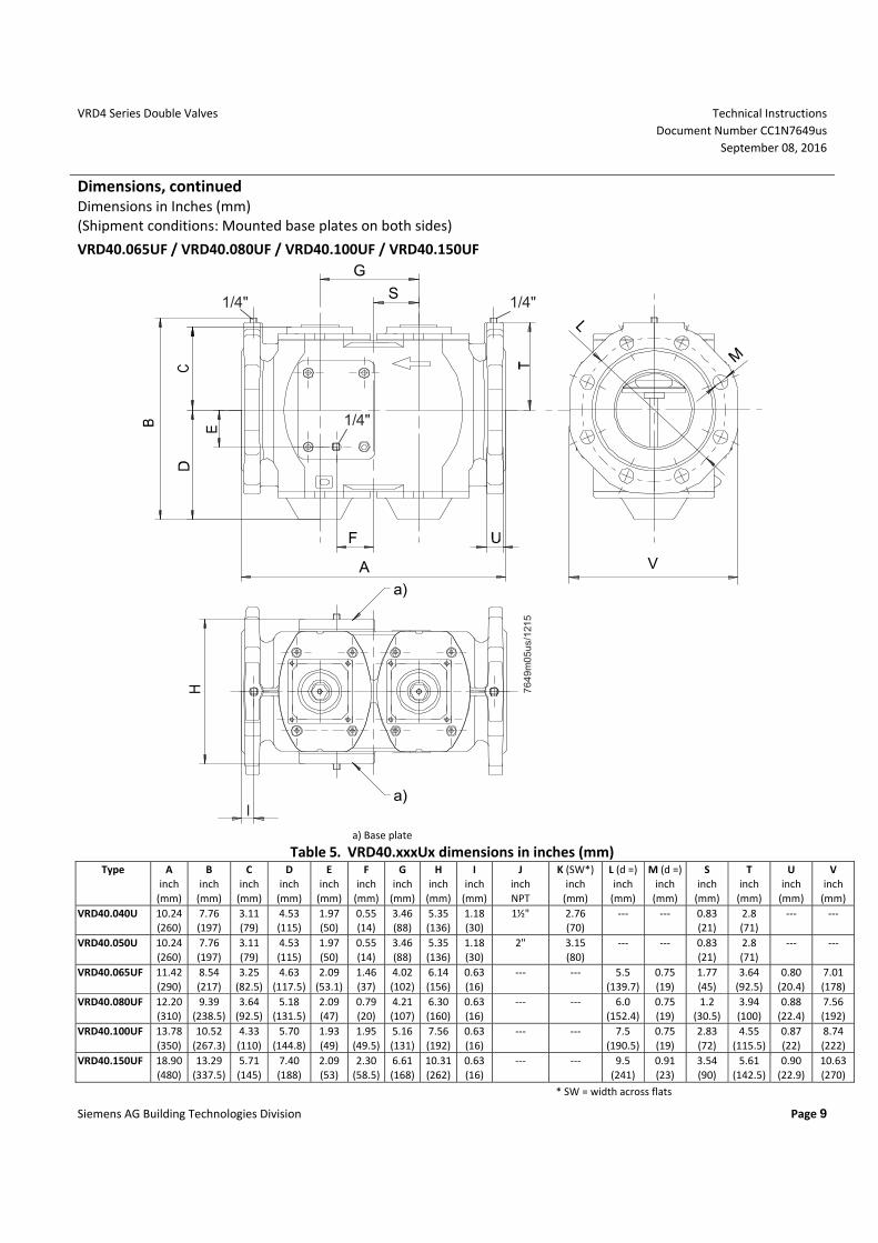
Dimensions, continued Dimensions in Inches (mm) (Shipment conditions: Mounted base plates on both sides)
VRD40.065UF / VRD40.080UF / VRD40.100UF / VRD40.150UF
M
V
S
G
A
F
a)
a)
76
49
m0
5u
s/1
215
1/4" 1/4"
1/4"
a) Base plate
Table 5. VRD40.xxxUx dimensions in inches (mm) Type A
inch (mm)
B inch
(mm)
C inch
(mm)
D inch
(mm)
E inch
(mm)
F inch
(mm)
G inch
(mm)
H inch
(mm)
I inch
(mm)
J inch NPT
K (SW*) inch
(mm)
L (d =) inch
(mm)
M (d =) inch
(mm)
S inch
(mm)
T inch
(mm)
U inch
(mm)
V inch
(mm) VRD40.040U 10.24
(260) 7.76 (197)
3.11 (79)
4.53 (115)
1.97 (50)
0.55 (14)
3.46 (88)
5.35 (136)
1.18 (30)
1½" 2.76 (70)
--- --- 0.83 (21)
2.8 (71)
--- ---
VRD40.050U 10.24 (260)
7.76 (197)
3.11 (79)
4.53 (115)
1.97 (50)
0.55 (14)
3.46 (88)
5.35 (136)
1.18 (30)
2" 3.15 (80)
--- --- 0.83 (21)
2.8 (71)
--- ---
VRD40.065UF 11.42 (290)
8.54 (217)
3.25 (82.5)
4.63 (117.5)
2.09 (53.1)
1.46 (37)
4.02 (102)
6.14 (156)
0.63 (16)
--- --- 5.5 (139.7)
0.75 (19)
1.77 (45)
3.64 (92.5)
0.80 (20.4)
7.01 (178)
VRD40.080UF 12.20 (310)
9.39 (238.5)
3.64 (92.5)
5.18 (131.5)
2.09 (47)
0.79 (20)
4.21 (107)
6.30 (160)
0.63 (16)
--- --- 6.0 (152.4)
0.75 (19)
1.2 (30.5)
3.94 (100)
0.88 (22.4)
7.56 (192)
VRD40.100UF 13.78 (350)
10.52 (267.3)
4.33 (110)
5.70 (144.8)
1.93 (49)
1.95 (49.5)
5.16 (131)
7.56 (192)
0.63 (16)
--- --- 7.5 (190.5)
0.75 (19)
2.83 (72)
4.55 (115.5)
0.87 (22)
8.74 (222)
VRD40.150UF 18.90 (480)
13.29 (337.5)
5.71 (145)
7.40 (188)
2.09 (53)
2.30 (58.5)
6.61 (168)
10.31(262)
0.63 (16)
--- --- 9.5 (241)
0.91 (23)
3.54 (90)
5.61 (142.5)
0.90 (22.9)
10.63 (270)
* SW = width across flats
Technical Instructions VRD4 Series Double Valves Document Number CC1N7649us September 08, 2016
Page 10 Siemens AG Building Technologies Division
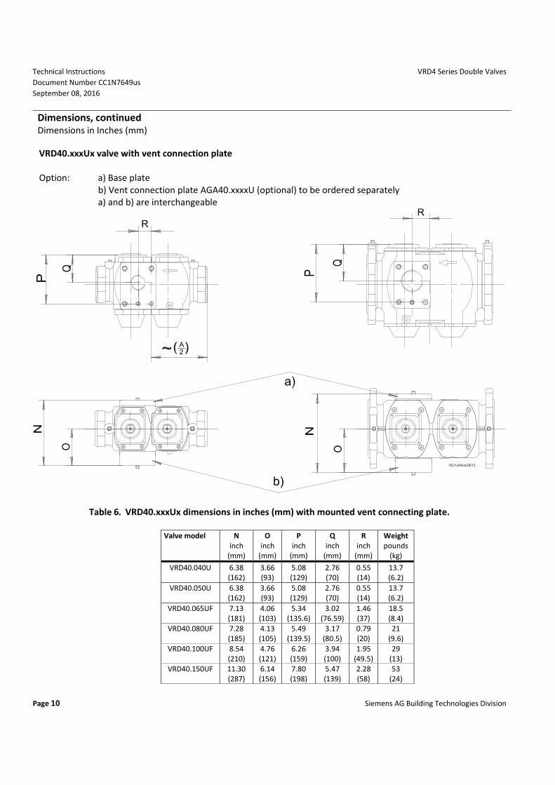
Dimensions, continued Dimensions in Inches (mm) VRD40.xxxUx valve with vent connection plate Option: a) Base plate b) Vent connection plate AGA40.xxxxU (optional) to be ordered separately a) and b) are interchangeable
2A
7631z49us/0815
Table 6. VRD40.xxxUx dimensions in inches (mm) with mounted vent connecting plate.
Valve model N inch
(mm)
O inch
(mm)
P inch
(mm)
Q inch
(mm)
R inch
(mm)
Weight pounds
(kg)
VRD40.040U 6.38 (162)
3.66 (93)
5.08 (129)
2.76 (70)
0.55 (14)
13.7 (6.2)
VRD40.050U 6.38 (162)
3.66 (93)
5.08 (129)
2.76 (70)
0.55 (14)
13.7 (6.2)
VRD40.065UF 7.13 (181)
4.06 (103)
5.34 (135.6)
3.02 (76.59)
1.46 (37)
18.5 (8.4)
VRD40.080UF 7.28 (185)
4.13 (105)
5.49 (139.5)
3.17 (80.5)
0.79 (20)
21 (9.6)
VRD40.100UF 8.54 (210)
4.76 (121)
6.26 (159)
3.94 (100)
1.95 (49.5)
29 (13)
VRD40.150UF 11.30 (287)
6.14 (156)
7.80 (198)
5.47 (139)
2.28 (58)
53 (24)
VRD4 Series Double Valves Technical Instructions Document Number CC1N7649us September 08, 2016
Siemens AG Building Technologies Division Page 11
Dimensions, continued Dimensions in Inches (mm)
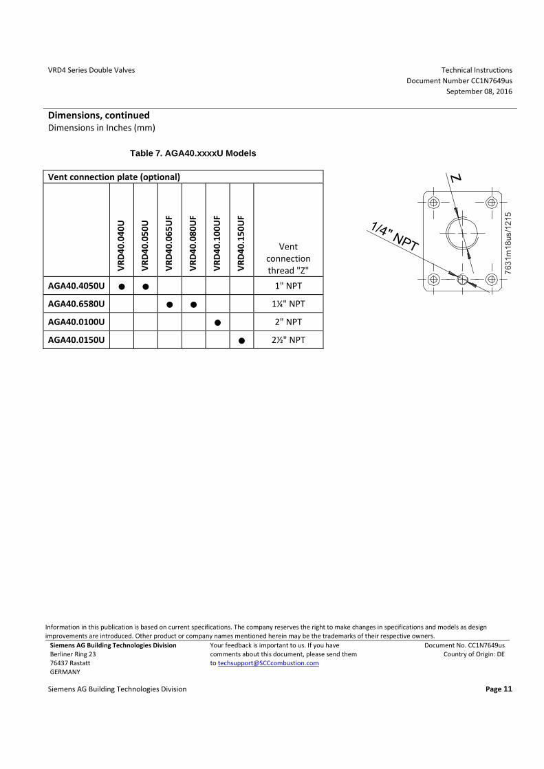
Table 7. AGA40.xxxxU Models Vent connection plate (optional)
1/4" NPT
763
1m18
us/1
215
VRD
40.0
40U
VRD
40.0
50U
VRD
40.0
65U
F
VRD
40.0
80U
F
VRD
40.1
00U
F
VRD
40.1
50U
F Vent
connection thread "Z"
AGA40.4050U ● ● 1" NPT
AGA40.6580U ● ● 1¼" NPT
AGA40.0100U ● 2" NPT
AGA40.0150U ● 2½" NPT
Information in this publication is based on current specifications. The company reserves the right to make changes in specifications and models as design improvements are introduced. Other product or company names mentioned herein may be the trademarks of their respective owners.
Siemens AG Building Technologies Division Berliner Ring 23 76437 Rastatt GERMANY
Your feedback is important to us. If you have comments about this document, please send them to [email protected]
Document No. CC1N7649us Country of Origin: DE