Embed Size (px)
Citation preview

954 IEEE TRANSACTIONS ON ROBOTICS AND AUTOMATION, VOL. 19, NO. 6, DECEMBER 2003
Workspace Analysis and Optimal Design of a 3-Leg6-DOF Parallel Platform Mechanism
Bruno Monsarrat and Clément M. Gosselin, Member, IEEE
Abstract—A new class of six-degree-of-freedom (DOFs) spatialparallel platform mechanism is considered in this paper. The ar-chitecture consists of a mobile platform connected to the base bythree identical kinematic chains using five-bar linkages. Recent in-vestigations showed that parallel mechanisms with such a topologyfor the legs can be efficiently statically balanced using only lightelastic elements. This paper follows up with a workspace analysisand optimization of the design of that parallel mechanism. Morespecifically, considering a possible industrial application of the ar-chitecture as a positioning and orienting device of heavy loads,an optimization procedure for the maximization of the volume ofthe three-dimensional (3-D) constant-orientation workspace of themechanism is first presented. As the mechanism could also havegreat potential as a motion base for flight simulators, we develophere a discretization method for the computation and graphicalrepresentation of a new workspace with coupled translational androtational DOFs. This workspace can be defined as the 3-D spacewhich can be obtained when generalized coordinates and tor-sion angle in the tilt-and-torsion angles parametrization are con-stant. A second procedure is then presented for the maximizationof the volume of this second subset of the complete workspace. Forboth approaches, our purpose is to attempt an optimal design ofthe mechanism by maximizing the volume of the associated 3-DCartesian region that is free of critical singularity loci.
Index Terms—Design, optimization, parallel manipulator, singu-larity-free workspace.
I. INTRODUCTION
DUE TO THEIR properties of increased nominal load-to-weight ratio, structural rigidity, positioning accuracy, and
dynamic performances, parallel mechanisms have been exten-sively studied over the last 30 years (see [28] for a detailedreview on parallel robots). Moreover, during the past decade,they have started to receive considerable attention by manufac-turers, finding various commercial applications such as motionsimulators, milling machines, assembly cells, and many others.However, in industrial applications of such mechanisms, wheredisplacements of heavy loads are involved, the size of the ac-tuators and the inherent operating costs are increased substan-tially. This motivated the development of parallel architectures
Manuscript received October 9, 2001; revised September 12, 2002. This paperwas recommended for publication by Associate Editor M. Shoham and EditorI. Walker upon evaluation of the reviewers’ comments. This work was sup-ported under research grants from the Natural Sciences and Engineering Re-search Council of Canada (NSERC).
B. Monsarrat is with the Aerospace Manufacturing Technology Centre, NRCInstitute for Aerospace Research, Montreal, QC H4T 1W5, Canada (e-mail:[email protected]).
C. M. Gosselin is with the Department of Mechanical Engineering, Laval Uni-versity, Quebec City, QC G1K 7P4, Canada (e-mail: [email protected]).
Digital Object Identifier 10.1109/TRA.2003.819603
Fig. 1. Initial prototype of the three-leg statically balanced 6-DOF parallelplatform mechanism (built in [17]).
that can be statically balanced. A mechanism is statically bal-anced if its potential energy is constant for all possible configu-rations, i.e., zero actuator forces/torques are required wheneverthe manipulator is at rest in any configuration. To the knowledgeof the authors, static balancing of spatial six-degree-of-freedom(DOF) parallel manipulators was first introduced in [18], [19],[34], and [35]. Two static balancing methods, namely, coun-terweights and springs, were used. Moreover, [10] presenteda class of spatial parallel platform mechanisms of novel archi-tecture that is suitable for static balancing. The particular mor-phology of the kinematic chains connecting the base to the mo-bile platform (referred to aslegsin this paper), based on five-barlinkages and similar to what was used in [33], allows an ef-ficient static balancing using only springs. The sufficient con-ditions on the kinematic parameters that guarantee static bal-ancing were derived for that class. A prototype with three iden-tical legs was designed in [17] in accordance with the static bal-ancing-related constraints (see Fig. 1). The figure illustrates theactuation scheme chosen for the prototype.
Subsequently, a kinematic study of that mechanism class waspresented in [9]. An analytical formulation for the inverse kine-matics was presented and an expression of the Jacobian matrixwas obtained in a general form. Closed-form expressions for thesingularity loci were also determined for a second case of actu-ation, namely, for the case where the rotation angle around thevertical axis and the angle between the two proximal links of theparallelogram are actuated for each leg. In addition, [29] recently
1042-296X/03$17.00 © 2003 IEEE

MONSARRAT AND GOSSELIN: WORKSPACE ANALYSIS AND OPTIMAL DESIGN OF A 3-LEG 6-DOF PARALLEL PLATFORM MECHANISM 955
presented a singularity analysis of this three-leg 6-DOF parallelmechanism using Grassmann line geometry. In the latter refer-ence, the Jacobian matrix was determined in a very compact formusing the principle of virtual work, and closed-form expressionswere obtained for the singularity loci of the mechanism with anactuation scheme identical to what was used for the previouslydescribed prototype. References [21] and [22] also presented thedesignofasmall-scaleprototypewith four legs,anddiscussed thecritical issues for the practical implementation of a statically bal-anced 6-DOF parallel platform mechanism. These recent worksalso addressed the kinematic design of such an architecture viaa maximization of the approximated volume of the constant-ori-entation workspace, defined as the set of all positions that can beattainedbya referencepointof themobileplatfomwhen the latteris kept at a constant orientation, the workspace being computedusing the geometric approach proposed in [13].
Subsequently, when the kinematic synthesis of parallel mech-anisms comes into practice, it appears that several approacheshave been proposed in the literature. In the first approach, op-timum characteristics are obtained by resorting to three criteria,namely: 1) symmetry considerations; 2) the maximization of thevolume of the associated workspace; and 3) the minimization ofthe condition number of the Jacobian matrix in order to achievea design as close to kinetostatic isotropy as possible ([11], [12],[16], and [24]). A weighted combination of these criteria com-bined with a minimization of the global dexterity index [14] wasrecently used in [2] to enhance the kinematic performances ofa parallel 3-DOF spherical haptic device. Some authors havealso investigated the parameter design of spatial parallel manip-ulators whose workspace has to include a prescribed volume.The latter design criterion was implemented using the followingmajor approaches, namely: 1) in [5] and [6] by solving an opti-mization problem using genetic algorithms; 2) in [27] by solvingthe equations of the inverse kinematics for a set of design pa-rameters and then by computing the suitable intersections be-tween the allowable regions associated with the leg lengths,the range of motion of the passive joints, and the leg interfer-ences; 3) by defining the objective complete workspace by a setof points in the six-dimensional (6-D) space for which the op-timum values of the design parameters are solved using an ana-lytical formulation for the direct and inverse kinematics [7]; and4) by using a constrained optimization scheme to ensure that theworkspace volume is as close as possible to a specified volume([30] and [31]). Another criterion for optimum kinematic de-sign consists of the synthesis of a parallel mechanism whoseprescribed workspace is free of singularities [32].
In this paper, we address the parameter design of the three-legstatically balanced 6-DOF parallel manipulator shown in Fig. 1.This initial version of the mechanism was designed consideringa unique design criterion, i.e., the fulfillment of the static bal-ancing-related constraints. In spite of feasible design character-istics being determined, it appeared that the kinematic perfor-mances of the resulting mechanism were not satisfactory, viz.: 1)its workspace capability was limited; 2) it was shown in [29] thatits workspace contains singularity surfaces that have a criticalimpact on the set of Cartesian points that are reachable in prac-tice by the end-effector; and 3) the initial version of the manip-ulator had been inopportunely designed such that its workspace
was divided into two connected regions separated by a criticalsingular configuration corresponding exactly to its neutral posi-tion (a singularity occurs when the mobile platform is parallel tothe base and rotated by an angle equal to zero about the verticalaxis [29]). The mechanism and the notation used to describeits configuration will be reviewed in Section II. The current de-sign and the set of design parameters will also be introduced atthis stage. Subsequently, numeric procedures for a combined en-hancement of the workspace capabilities and kinematic perfor-mances of the mechanism will be presented in this paper. Morespecifically, this will be done by considering two possible com-mercial applications for the mechanism, each of them leading toa maximization of a particular 3-D subset of the 6-D completeworkspace of the manipulator. Such an approach is consistent,as no method exists for the computation and graphical represen-tation of the complete workspace of parallel manipulators.
1) Design 1: This statically balanced parallel mechanismcould find great potential as a positioning and orientingdevice of heavy loads. In this context, we make the prelim-inary assumption that allowable rotational displacementsof the pitch, yaw, and roll angles greater or equal towill be considered satisfactory for such an application. Inaddition, the translational DOFs of the mobile platformneed to be maximized, ensuring simultaneously that theassociated range of motion does not contain any singularconfiguration. Therefore, an optimization procedure forthe maximization of the volume of the singularity-freeregion of the 3-D constant-orientation workspace of theparallel mechanism will be presented in Section III.
2) Design 2:The mechanism could also find great potentialas a motion base for flight simulators. For such an ap-plication, it is well known that the motion of the cockpitdoes not require a large range of motion in theplane and about the mobile axis. It is, rather, neces-sary to maximize the rotational and translational displace-ments of the three remaining generalized coordinates, i.e.,the rotational displacements associated with the roll andpitch angles, and the translational displacement along the
axis. We, therefore, make the preliminary assumptionthat, for the scale-down version of the mechanism con-sidered, allowable translational displacements greater orequal to mm in the and directions, and allow-able rotational displacements greater or equal toabout the mobile axis will be considered satisfactory forsuch an application. As no method has been proposed inthe literature for the computation and plotting of this 3-Dworkspace, a discretization method for the computationand graphical representation of this new workspace withcoupled translational and rotational DOFs is proposed inSection IV. A second optimization procedure is then pre-sented for the maximization of the volume of this secondsubset of the complete workspace. Our purpose here isto attempt a second optimal design of the mechanism bymaximizing the volume of the associated 3-D Cartesianregion that is also free of critical singularity loci.
Note that both optimization procedures are completely in-dependent, and are used to improve the performances of this

956 IEEE TRANSACTIONS ON ROBOTICS AND AUTOMATION, VOL. 19, NO. 6, DECEMBER 2003
Fig. 2. Geometric parameters of the three-leg 6-DOF parallel manipulator.
three-leg statically balanced parallel mechanism with a viewto two distinct future applications. The resulting sets of designcharacteristics will finally be discussed and compared in Sec-tion IV-E.
II. EXISTING PROTOTYPE AND CHOICE
OF OPTIMIZATION PARAMETERS
A. Review of the Architecture
The type of mechanism considered in this paper is shown inFig. 1. The architecture consists of a fixed base and a mobileplatform connected by three legs. Theth leg is attached to thebase at point , and to the mobile platform at point (seeFig. 2). In order to give symmetry to the architecture, the attach-ment points on the base and mobile platforms form equilateraltriangles. We define a geometric parameterthat is used to de-scribe the position of points , making the assumption thatthe attachment points of the three legs are equally spaced on acircle of radius with center at point , i.e., , for
. Starting from the base, theth leg of the mechanismis a serial arrangement of a passive vertical revolute joint asso-ciated with angle , a five-bar linkage located in theplane, and a passive spherical joint connecting the leg to themobile platform at point . The two proximal links of thefive-bar linkage are mounted using two actuated revolute jointswith coincident axes, associated, respectively, with anglesand . The whole leg can rotate about the verticalaxis atpoint , that rotation including the mounting points of thesprings at the base, so that the springs always remain in theplane of the five-bar linkage. The mobility of the parallelmechanism under study can be determined by application of theChebyshev–Grübler–Kutzbach formula, i.e.,
(1)
where and are, respectively, the number of bodies (includingthe base) and number of joints of the mechanism, andis thenumber of DOFs of joint . Given the particular topologicalstructure of the mechanism, and considering that each five-bar
linkage is kinematically equivalent to a planarRR linkage, wehave , and , the mobility ofthe mechanism thus being equal to six. Correspondingly, this6-DOF mechanism is actuated by a set of six input angles,and , for 1–3.
Definition of Termsangles describing the configuration of theth leg
;origin of the fixed frame located at equal distancefrom the three points , for ;centroid of the mobile platform;vector connecting the origin of the fixed frame tothe centroid (position vector of the platform);rotation matrix representing the orientation of the plat-form and defined by Euler angles ;vector connecting the origin of the fixed frameto theattachment point of leg at the base;vector connecting the origin of the fixed frameto theattachment point of leg at the platform;vector from centroid to the attachment point ofthe th leg with respect to the mobile frame ;distance between point and the attachment pointsof the th leg to the mobile platform, i.e., , for
;length of the th link of leg , for and
.We define a fixed-base reference framewith its origin at
point , and with axes , and such that the baseaxis co-incides with the axis of symmetry of the mechanism. A mobileframe is chosen fixed to the mobile platform at point,with axes , and , such that the mobile axis coincideswith the axis of symmetry. In thereference orientationof themobile platform, the orientation of the mobile frame coincideswith that of the base frame. This orientation will be representedhere by Euler angles , and . Note that different conven-tions for the Euler angles will be used in this paper in correspon-dence with the particular 3-D subset of the complete workpsaceto be computed. The set of Euler angles and the correspondingrotation matrices will be described in Sections III and IV, re-spectively. The position of the mobile platform is described bythe vector , which denotes the coordinates of thepoint and expressed in the reference frame. In this context,
denote the generalized coordinates of the ma-nipulator. The reader should refer to Fig. 2 and to the associateddefinition of terms for a description of the mechanism and itsconfiguration.
B. Balancing Conditions and Corresponding Choice ofOptimization Parameters
As mentioned previously, the geometric characteristics of theprototype shown in Fig. 1 led to an architecture which may notbe optimal from a kinematic perspective. This motivated the im-plementation of optimization procedures for the improvement ofthe workspace capabilities and kinematic performances of themechanism. However, this optimization problem cannot be ad-dressed using a procedure similar to what can be implemented
MONSARRAT AND GOSSELIN: WORKSPACE ANALYSIS AND OPTIMAL DESIGN OF A 3-LEG 6-DOF PARALLEL PLATFORM MECHANISM 957
for conventional nonbalanced spatial parallel manipulators. In-deed, the design of such a statically balanced manipulator im-poses that the optimization of the kinematic parameters of themechanism be determined through a two-step approach.
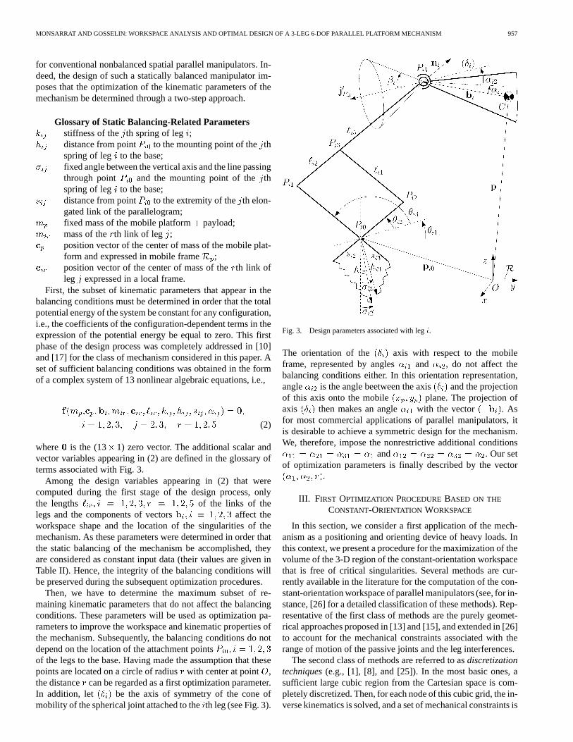
Glossary of Static Balancing-Related Parametersstiffness of the th spring of leg ;distance from point to the mounting point of thethspring of leg to the base;fixed angle between the vertical axis and the line passingthrough point and the mounting point of thethspring of leg to the base;distance from point to the extremity of theth elon-gated link of the parallelogram;fixed mass of the mobile platform payload;mass of the th link of leg ;position vector of the center of mass of the mobile plat-form and expressed in mobile frame ;position vector of the center of mass of theth link ofleg expressed in a local frame.
First, the subset of kinematic parameters that appear in thebalancing conditions must be determined in order that the totalpotential energy of the system be constant for any configuration,i.e., the coefficients of the configuration-dependent terms in theexpression of the potential energy be equal to zero. This firstphase of the design process was completely addressed in [10]and [17] for the class of mechanism considered in this paper. Aset of sufficient balancing conditions was obtained in the formof a complex system of 13 nonlinear algebraic equations, i.e.,
(2)
where is the (13 1) zero vector. The additional scalar andvector variables appearing in (2) are defined in the glossary ofterms associated with Fig. 3.
Among the design variables appearing in (2) that werecomputed during the first stage of the design process, onlythe lengths of the links of thelegs and the components of vectors affect theworkspace shape and the location of the singularities of themechanism. As these parameters were determined in order thatthe static balancing of the mechanism be accomplished, theyare considered as constant input data (their values are given inTable II). Hence, the integrity of the balancing conditions willbe preserved during the subsequent optimization procedures.
Then, we have to determine the maximum subset of re-maining kinematic parameters that do not affect the balancingconditions. These parameters will be used as optimization pa-rameters to improve the workspace and kinematic properties ofthe mechanism. Subsequently, the balancing conditions do notdepend on the location of the attachment pointsof the legs to the base. Having made the assumption that thesepoints are located on a circle of radiuswith center at point ,the distance can be regarded as a first optimization parameter.In addition, let be the axis of symmetry of the cone ofmobility of the spherical joint attached to theth leg (see Fig. 3).
Fig. 3. Design parameters associated with legi.
The orientation of the axis with respect to the mobileframe, represented by angles and , do not affect thebalancing conditions either. In this orientation representation,angle is the angle beetween the axis and the projectionof this axis onto the mobile plane. The projection ofaxis then makes an angle with the vector . Asfor most commercial applications of parallel manipulators, itis desirable to achieve a symmetric design for the mechanism.We, therefore, impose the nonrestrictive additional conditions
and . Our setof optimization parameters is finally described by the vector
.
III. FIRST OPTIMIZATION PROCEDUREBASED ON THE
CONSTANT-ORIENTATION WORKSPACE
In this section, we consider a first application of the mech-anism as a positioning and orienting device of heavy loads. Inthis context, we present a procedure for the maximization of thevolume of the 3-D region of the constant-orientation workspacethat is free of critical singularities. Several methods are cur-rently available in the literature for the computation of the con-stant-orientation workspace of parallel manipulators (see, for in-stance, [26] for a detailed classification of these methods). Rep-resentative of the first class of methods are the purely geomet-rical approaches proposed in [13] and [15], and extended in [26]to account for the mechanical constraints associated with therange of motion of the passive joints and the leg interferences.
The second class of methods are referred to asdiscretizationtechniques(e.g., [1], [8], and [25]). In the most basic ones, asufficient large cubic region from the Cartesian space is com-pletely discretized. Then, for each node of this cubic grid, the in-verse kinematics is solved, and a set of mechanical constraints is

958 IEEE TRANSACTIONS ON ROBOTICS AND AUTOMATION, VOL. 19, NO. 6, DECEMBER 2003
tested. In probably the most sophisticated and fastest discretiza-tion method, the boundary of the workspace is determined in aspherical coordinate system by discretizing the range of azimuthand zenith angles [8]. Despite such methods are computationallyintensive and give little information about the geometric natureof the workspace boundary, they can be easily applied to anytype of parallel manipulator for virtually any set of mechanicalconstraints. In addition to all conventional mechanical limits,it is intended here to incorporate the closed-form equations forthe singularity loci of the three-leg 6-DOF parallel mechanismin the set of kinematic constraints. For inherent complexity rea-sons, the discretization algorithm proposed in [8] was found tobe the most appropriate candidate to be used in the followingdesign procedure.
A. Conventional Mechanical Constraints
This section summarizes the conventional mechanicalconstraints that limit the constant-orientation workspace ofthe mechanism. As a preliminary, let us be precise that theorientation of the platform will be represented in this sectionby the Euler-angle convention that is defined by firstrotating the mobile frame about the baseaxis by an angle ,then about the new axis by an angle , and finally about themobile axis by an angle . For this choice of Euler angles,the singularity occurs at and the rotation matrix isdefined as
(3)
where , etc.Subsequently, there exists four main sets of basic mechanical
constraints that limit the constant-orientation workspace of thethree-leg parallel mechanism, viz.: 1) the limited length of thelegs; 2) the range of motion of the three spherical joints; 3) theleg interferences; and 4) additional constraints related to the me-chanical design.
1) Limited Length of the Legs:Let the orientation of the mo-bile platform be represented by the (33) orthogonal rotationmatrix . For a given position (vector) and orientation (matrix
) of the mobile platform, the necessary leg lengths, denoted by, are computed using the following relation, :
(4)
Then, the five-bar linkage structure of the legs imposes a lengthconstraint such that
(5)
where , and are, respectively, the lengths of the el-ements of leg (see Fig. 2), and and are constant termsused to account for the range of reachable positions by each par-allelogram structure.
2) Range of Motion of the Spherical Joints:Let be theunit vector collinear with the axis and expressed in the mo-bile frame (see Fig. 3). Let vector be the opposite vector,and with respect to the base frame, i.e., . Let
the maximum misalignment angle of that joint be. Then, thelimits on the mobile platform joint impose an angular con-straint such that, for
(6)
where unit vectors are defined as
(7)
and unit vectors are given by
(8)
where , etc.3) Leg Interferences:Let us make the assumption that the
elements of the three legs can be approximated by cylinders ofdiameter . We point out that, for most configurations of themobile platform, only strut collisions between segmentsand of leg with segment of leg are aconcern. Thus, the structure of the three-leg mechanism usingfive-bar linkages imposes a set of constraints, such that
distancedistance (9)
These contraint check equations require the computation of theminimum distance between two line segments, which requiresthe implementation of a multistep algorithm. We do not recallsuch an algorithm here due to space limitations, but we refer thereader to the one presented in [25].
4) Additional Constraints:The specific design of the baseplatform of the prototype imposes to consider the following con-straint:
(10)
B. Singularity Loci and Inherent Kinematic Constraints
In this section, the singularity loci of the three-leg parallelmechanism are summarized and their constitutive equations aregiven in closed form to be incorporated as kinematic constraintsin the following discretization algorithms. The singularities ofthe mechanism were determined in [29] using Grassmann linegeometry. Five families of singularities were identified.
1) The two links of the th leg are aligned, i.e.,. This defines, for each leg, the minimum and max-
imum spheres of radii and , respec-tively, with center at point of coordinates ,that constitute the boundary of the constant-orientationworkspace of the mechanism. The constraint expressedby (5) takes already care of this case.
2) When the mobile and base platforms are parallel, i.e.,, a singularity occurs when the angle of rotation
of the platform about the axis is equal to 0 or .

MONSARRAT AND GOSSELIN: WORKSPACE ANALYSIS AND OPTIMAL DESIGN OF A 3-LEG 6-DOF PARALLEL PLATFORM MECHANISM 959
Fig. 4. Legi of the mechanism (top view).
3) In the case of an arbitrary orientation of the mobile plat-form, a singular configuration occurs when the end-ef-fector is located on a quadratic surface represented in theCartesian space by
(11)
which correspond to either a hyperbolic, a parabolic, oran elliptic cylinder, oriented along theaxis. Coefficients
, are given in [29].The criticality of such singularities was shown in that ref-erence.
4) A singularity occurs when the platform is purely rotatedby about a median of triangle . Such sin-gularities will always be located far outside the workspaceboundary and will, therefore, be neglected here.
5) Additional singular configurations occur when the upperend of leg is exactly above its lower end, , for
. The corresponding singularity loci are threevertical lines that pass through the point of coordinates
. In practice, these lines can easilybe avoided during any trajectory tracking and will, there-fore, be neglected in the discretization procedure.
As it was found numerically that the left-hand expression in(11) is strictly positive inside the region that is free of such sin-gularities, it was finally decided to incorporate the following setof kinematic constraints:
(12)
(13)
C. Workspace Volume Optimization Algorithm
1) Preliminary Calculations:The consistency of the opti-mization process imposes that the angle between the leg andthe axis of symmetry of the spherical joints, projected onto the
plane, be equal to zero when the mobile platform is in theconfiguration . This ensures that the workspaceis computed with a starting appropriate neutral orientation of themobile platform about the vertical axis. In this context, a con-stant average value of angle, noted , is computed for eachvalue of parameter (see Fig. 4). Let be the projected dis-tance between the two attachment points of theth leg and
. For a given value of angle , the angle is readily de-termined by the set of equations
(14)
(15)
which leads to the following quadratic equation in :
(16)
with
(17)
As we only consider the positive values of angle, (16) resultsin two solutions. Then, it can be shown that the structure ofthe three-leg mechanism imposes that only the smallest of theremaining solutions has to be considered.
2) Review of the Discretization Technique for the Compu-tation of the Constant-Orientation Workspace:The discretiza-tion technique presented in [8] is based on the integrated imple-mentation of the following two algorithms.
Spherical Search Algorithm:Let us assume that the loca-tion of an approximated center of the workspace is knownfor a given orientation of the platform. This algorithm then con-ducts a search to determine the boundary of the workspace in aspherical coordinate system with center at point .The process of searching the entire space is accomplished bydiscretizing the range of azimuth and zenith anglesand .For each pair of them, the radius is incremented until a con-straint violation is detected. When a value foris found to belocated outside the workspace, which constitutes a first approx-imation for the location of the workspace boundary along thespherical ray, a second algorithm, referred to as theWorkspaceBoundary Algorithm, is used to refine the result.
Workspace Boundary Algorithm:For each pair of azimuthand zenith angles, this algorithm is used at the final stage ofthe search process. It is based on the use of aninterval-halvingsearch technique in order to guarantee thatis within ofthe workspace boundary, whereis a given error tolerance.
The consistency and accuracy of the method are demonstratedin [8] using various examples. We now present the algorithmfor the maximization of the volume of the 3-D region of theconstant-orientation workspace of the three-leg mechanism thatis free of critical singularity loci. The procedure is describedschematically in Fig. 5.
3) Algorithm for the Maximization of the Volume of the Sin-gularity-Free Region of the Constant-Orientation Workspace:
Initialize 3-D array with dimensions, where , and are, respectively, the
number of incremental steps corresponding to ,and .Start with initial values of optimization parameters
, and .For the current set , do:Define a cube-shaped grid whose equally-spacednodes describe positions of the mobile platform withinthe work volume of the mechanism. For each node ofthe grid whose position and orientation is known,angles are computed using theexpressions for the inverse kinematics [9]. Then, (5),(6), (9), (10), (12), and (13) are employed to check forany constraint violation. Using the results obtainedfrom testing these positions, the approximate location
960 IEEE TRANSACTIONS ON ROBOTICS AND AUTOMATION, VOL. 19, NO. 6, DECEMBER 2003
Fig. 5. Flowchart describing the first optimization procedure presented inSection III-C.3.
of the center of the workspace can be determined.This center will serve as the origin of a sphericalcoordinate system .Initialize matrix with dimensions ,where and define the number of incre-mental steps that constitute the spherical grid for
and .Solve (16) to compute the corresponding average an-gular value .Use theSpherical Search Algorithmand theWorkspaceBoundary Algorithmpresented in [8] to computethe corresponding region of the constant-orien-tation workspace that is free of critical singular-ities in spherical coordinates for the orientation
. For each node of the spher-ical grid, the inverse kinematic problem is solved, andthe constraint violations are detected by (5), (6), (9),(10), (12), and (13). The values of radius at thepoints of constraint violation are stored into matrix
.Each sector of the resulting workspace being approx-imated by a four-sided pyramid defined by four adja-cent workspace data point with origin at point
, determine the volume of the workspace by sum-ming the calculated volumes of all the sectors. Thevalue of the workspace volume is then stored in the3-D array .Repeat steps S3–S8 for all possible combinations ofoptimization parameters .Plot resulting data to find the set of parameters
which corresponds to a maximal volumeof the singularity-free workspace of the three-legmechanism.
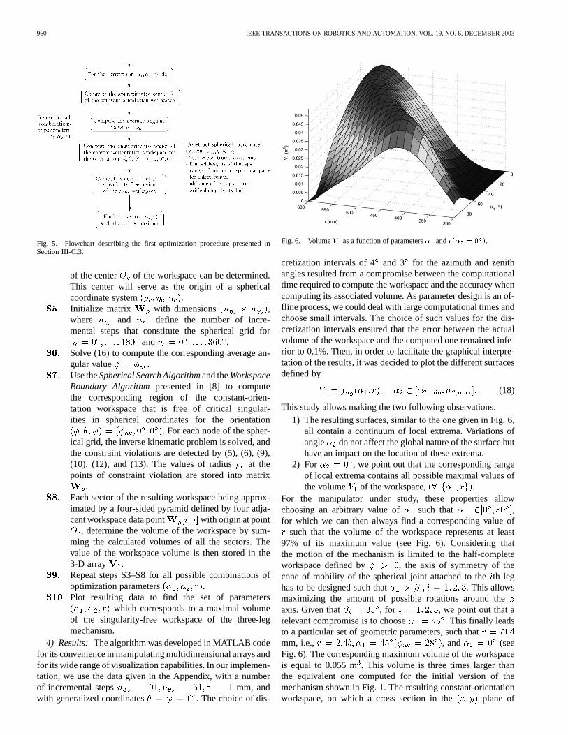
4) Results: The algorithm was developed in MATLAB codefor its convenience in manipulating multidimensional arrays andfor its wide range of visualization capabilities. In our implemen-tation, we use the data given in the Appendix, with a numberof incremental steps mm, andwith generalized coordinates . The choice of dis-
Fig. 6. VolumeV as a function of parameters� andr(� = 0 ).
cretization intervals of 4 and 3 for the azimuth and zenithangles resulted from a compromise between the computationaltime required to compute the workspace and the accuracy whencomputing its associated volume. As parameter design is an of-fline process, we could deal with large computational times andchoose small intervals. The choice of such values for the dis-cretization intervals ensured that the error between the actualvolume of the workspace and the computed one remained infe-rior to 0.1%. Then, in order to facilitate the graphical interpre-tation of the results, it was decided to plot the different surfacesdefined by
(18)
This study allows making the two following observations.
1) The resulting surfaces, similar to the one given in Fig. 6,all contain a continuum of local extrema. Variations ofangle do not affect the global nature of the surface buthave an impact on the location of these extrema.
2) For , we point out that the corresponding rangeof local extrema contains all possible maximal values ofthe volume of the workspace, .
For the manipulator under study, these properties allowchoosing an arbitrary value of such that ,for which we can then always find a corresponding value of
such that the volume of the workspace represents at least97% of its maximum value (see Fig. 6). Considering thatthe motion of the mechanism is limited to the half-completeworkspace defined by , the axis of symmetry of thecone of mobility of the spherical joint attached to theth leghas to be designed such that . This allowsmaximizing the amount of possible rotations around theaxis. Given that , for , we point out that arelevant compromise is to choose . This finally leadsto a particular set of geometric parameters, such thatmm, i.e., , and (seeFig. 6). The corresponding maximum volume of the workspaceis equal to 0.055 m. This volume is three times larger thanthe equivalent one computed for the initial version of themechanism shown in Fig. 1. The resulting constant-orientationworkspace, on which a cross section in the plane of

MONSARRAT AND GOSSELIN: WORKSPACE ANALYSIS AND OPTIMAL DESIGN OF A 3-LEG 6-DOF PARALLEL PLATFORM MECHANISM 961
Fig. 7. (a) Perspective and (b) top views of the maximal singularity-freeconstant-orientation workspace of the mechanism(� ; � ; r) =(45 ; 0 ; 504) mm, (�; �; ) = (28 ; 0 ; 0 ).
the singularity surface given by (13) is superimposed (dashedcircle), is represented in Fig. 7. Note, correspondingly, that theoptimized workspace is much smaller that the 3-D region freeof singularities, i.e., the constraint violation expressed by (13)was never encountered for this set of design parameters. In thatcase, the region of the workspace that is free of singularities isconstituted by the whole workspace. In fact, it was observedduring the optimization process that, when the singularitysurface is tangent to the boundary of the workspace, the radiusof the cylinder of singularities and the corresponding volumeof the singularity-free workspace are much smaller than thosefor the optimum case. Such a result is all the more interestingas it means that the Jacobian matrix of the mechanism will bewell conditioned throughout and even near the boundary of theworkspace. The design characteristics for this first optimizationare summarized in Table I.
Note: The optimization procedure was implemented forthe case where , which could appear restrictivefrom a design perspective. However, allowable rotational dis-placements of the pitch, yaw, and roll angles greater thanwere obtained, i.e., and ,thus exceeding the desired ranges of possible rotations ofthe mobile platform as provided in Section I for a com-mercial application of the mechanism as a positioning andorientating device of heavy loads. Let us mention that, ifrotational displacements inferior to had been obtained,an alternative approach consisted in the determination of
TABLE IGEOMETRIC DATA BEFORE/AFTER OPTIMIZATION (4q DENOTESMAXIMUM
ALLOWABLE DISPLACEMENT FORCOORDINATE q, AND ROTATIONS ARE
REPRESENTED BYZXY EULER ANGLES)
the optimum set such that the average volumebe maximum,
where , and and are the number ofdiscrete intervals over and , respectively.
It should finally be highlighted that, for the three-leg mecha-nism, neglecting the mechanical constraint associated with therange of motion of the spherical joints would have led to a max-imal volume equal to 0.085 mfor the geometry and
. Thus, neglecting these mechanical constraints can in-troduce significant errors and lead to a feasible but nonoptimaldesign.
IV. SECOND OPTIMIZATION PROCEDUREBASED ON A
NEW WORKSPACEWITH COUPLED TRANSLATIONAL
AND ROTATIONAL GENERALIZED COORDINATES
In this section, we consider a second application of the mech-anism as a motion base for flight simulators. As discussed inSection I, we present a procedure for the maximization of thevolume of the 3-D workspace with constant translationaland
coordinates and constant rotation angle of the platform aboutthe mobile axis. Our purpose is to attempt a second optimaldesign of the mechanism by maximizing the volume of the as-sociated 3-D Cartesian region that is also free of critical singu-larity loci. As no method has been proposed in the literature forthe computation and plotting of this workspace, a discretizationmethod for the computation and graphical representation of thisnew workspace with coupled translational and rotational DOFsis proposed in this section. Note, correspondingly, that the com-putation of this workspace is also of great interest in the con-text of analysis and design of new motion simulators with onlythree or four DOFs, currently developed for their lower manu-facturing cost and simplified control algorithms.
A. Representation of the Platform Orientation
One of the major issues associated with the computation andgraphical representation of such a workspace is the choice ofthe set of Euler angles to describe the orientation of the mo-bile platform. Various sets of Euler angles exist, but

962 IEEE TRANSACTIONS ON ROBOTICS AND AUTOMATION, VOL. 19, NO. 6, DECEMBER 2003
Fig. 8. Representation of the platform orientation using the tilt-and-torsionangles [4] (figure courtesy of Dr. I. A. Bonev).
their interpretation is generally nonintuitive. Let us recall thatour purpose is to compute the 3-D workspace for the case whenthe rotation angle of the platform about the mobile axis, re-ferred here to as thetorsion angle, and the and coordinatesof a reference point of the platform, are prescribed. Hence, weimpose the first requirement that Euler anglesand must de-scribe exactly the direction of the axis with respect to thefixed frame . Moreover, we impose the second requirementthat Euler angles and must correspond to the azimuth andzenith angles that define the direction of theaxis in a spher-ical coordinate system, thus ensuring a easy and intuitive in-terpretation of the platform orientation. These requirements areadequately met by thetilt-and-torsionangles (see Fig. 8). Thisorientation parametrization was introduced in [3] for the com-putation of the orientation workspace of parallel manipulators,defined as the set of all attainable orientations of the platformabout a point being fixed with respect to the base frame, andlater applied to the analysis of constrained manipulators in [4].This modified set of Euler angles was also used in [20] for rep-resenting the 2-D orientation workspace of Gough–Stewart par-allel manipulators. In this orientation representation, the mobileplatform is first rotated about the baseaxis by an angle , thenabout the new axis by an angle, and finally about the mobile
axis by an angle . The singularity occurs at , andthe corresponding rotation matrix is given by
(19)
A one-to-one correspondence exists between the orientationsof the mobile platform and the orientation parametrizationused when angles , and are defined over the intervals
, and , respectively.As we will see in Section IV-C, this particular orientationparametrization allows the representation of the workspacewith , and constant as a single volume with a compactshape.
B. Represention of the Workspace
It was chosen to represent the workspace with coupled trans-lational/rotational DOFs in a cylindrical coordinate system,
where and are the polar angles and is exactly thecoordinate, for two main reasons. First, for each plane definedby , the process of searching the workspace boundaryalways starts from an approximated neutral configuration, andthe workspace is, therefore, not delimited by an inner boundary.This ensures a representation of the workspace as a singlevolume whose boundary is always visible and easy to interpret.Secondly, for each plane , all possible orientationswill be attainable from the approximated neutral configurationthrough a continuous motion without violating any mechanicalconstraint, thus avoiding the issue related to thecompatibilityconstraint, as reported in [3].
We now present the discretization algorithm for the compu-tation of the workspace with coordinates , and constant.This algorithm is a modified version of the one that was first in-troduced in [3] to compute the orientation workspace, in whichangle is substituted by coordinate. It is intrinsically appli-cable to any type of spatial parallel manipulator with the afore-mentioned DOFs of the platform, for any set of mechanical con-straints. Let , and be the constant values for , and
. Finally, let be the coordinate of a point that is locatedabove the top of the workspace, the algorithm is then as follows.
C. Discretization Algorithm for the Workspace With CoupledTranslational/Rotational DOFs
Set . Define a linear gridalong the axis whose equally spaced nodes describepositions of the platform within the work volume ofthe mechanism. Then, solve the inverse kinematicsand apply the set of constraint checks for each nodeof the grid. Using the results obtained from testingthese positions, the approximatecoordinate of theworkspace center can be determined.Set . Assume that is thecenter of the horizontal cross section of the workspacefor .Initialize matrices and , with dimensions
, where is the number of equallyspaced planes between and atwhich the workspace will be computed, and is thenumber of discrete points to be computed at each plane
. These matrices will store, respectively, thevalues of and for the points defining the upper partof the workspace.For the current , construct a polar coordinate systemat . Starting at equally spaced angles, incre-ment the polar ray, solve the inverse kinematics, andapply the set of constraint checks until a constraint isviolated. The values for and at the points of con-straint violation are stored into the two matricesand .Compute the geometric center of theworkspace cross section, which will serve as theassumed center for the next cross section. Set
.Perform steps S4 and S5 until the workspace cross sec-tion is a single point (i.e., is reached).

MONSARRAT AND GOSSELIN: WORKSPACE ANALYSIS AND OPTIMAL DESIGN OF A 3-LEG 6-DOF PARALLEL PLATFORM MECHANISM 963
Assign to the values that were stored in stepS5 for . Set .Perform steps S3–S6 in a similar way with decreasing
coordinates to determine the lower part of theworkspace. The points defining the lower part of theworkspace are stored into matrices and .
D. Workspace Volume Optimization Procedure
The algorithm presented in Section IV-C will be the core ofa second optimization procedure for the maximization of thevolume of the singularity-free workspace with , and con-stant of the three-leg mechanism shown in Fig. 1.
1) Modified Set of Constraints:In the following optimiza-tion algorithm, all conventional mechanical constraints definedby (5), (6), (9), and (10) will still be considered. However, theparticular representation of the workspace with, and con-stant imposes that the kinematic constraints associated with thecritical singularity loci reviewed in Section III-B to be refor-mulated. As a first iteration of the optimization algorithm willbe run for the case mm mm , which will beshown in Section IV-E to be sufficient to obtain very satisfac-tory results, (11), describing the critical singularity loci, will bereadily rewritten under the form
(20)
Then, we substitute the tilt-and-torsion angles in (20) and weperform the tangent-half substitution
(21)
with . After factorization, multiplication by, and rearranging, (20) reduces to the form
(22)
The corresponding singularity loci are independent from thecoordinate and are, therefore, identical, whatever the cross sec-tion at of the workspace with , and constant tobe considered. Then, the orientation representation imposes thatwe compute only positive values for, and the set of kinematicconstraints is finally given by
(23)
(24)
where
and .2) Algorithm for the Maximization of the Volume of the Sin-
gularity-Free Workspace With , and Constant: From amethodological perspective, the procedure for the maximizationof the volume of the singularity-free region of the workspacewith , and constant of the three-leg mechanism is struc-turally very similar to the one used for the achievement of thefirst optimum design as described in Section III-C.3. It is de-scribed schematically in Fig. 9. Note that, in this case, angle
Fig. 9. Flowchart describing the second optimization procedure presented inSection IV-D.2.
is still computed by (16), in which angle is substitutedby angle in correspondence with the change of orientationparametrization. In the part of the algorithm dedicated to thecomputation of the workspace, we use
(25)
In addition, the set of constraint checks described by (5), (6),(9), (10), (23), and (24) are applied (more specifically in stepsS1 and S4 in Section IV-C) to account for all conventional me-chanical constraints and simultaneously ensure that the resultingworkspace be free of critical singularities. Finally, for a givenset , the volume of the workspace is computed as fol-lows. Each sector of the workspace is first approximated by atriangular prism defined by four adjacent workspace data pointswhose volume is easily computed. Then, the volumeof theworkspace with , and constant is determined by summingthe calculated volumes of all the sectors constituting the upperand lower parts of the workspace.
E. Discussion of Results
This second algorithm was also developed in MATLAB codeusing data given in the Appendix, with a number of incrementalsteps , and . Then, we used aprocedure similar to the one described in Section III-C.4. Wenoticed that the maximal value of the volume of the sin-gularity-free workspace with , and constant is obtainedwhen . Thus, considering the surface de-fined by , we pointed out that aunique local extrema exits with coordinates mm, i.e.,
, and , as shown in Fig. 10. This leads to amaximum volume equal to 0.245 mrad . The correspondingworkspace is graphically represented in Fig. 11. Note, corre-spondingly, how the representation using the modified Euler an-gles in a cylindrical coordinate system allowed one to displaythe workspace as an easy-to-interpret single volume having asimple shape.
Note: The procedure was implemented for the case wheremm. However, allowable translational displacements
in the and directions greater than mm were obtained,i.e., mm, thus exceeding the desired ranges

964 IEEE TRANSACTIONS ON ROBOTICS AND AUTOMATION, VOL. 19, NO. 6, DECEMBER 2003
Fig. 10. VolumeV as a function of� andr(� = 30 ).
Fig. 11. (a) Perspective and (b) top views of the maximalsingularity-free workspace with x; y, and constant(� ;� ; r) = (85 ; 30 ; 280 mm); (x; y; ) = (0 mm; 0 mm; 38 ).
of possible translations of the platform as provided in Section Ifor a commercial application of the mechanism as a motionbase for flight simulators. If nonsatisfactory allowable displace-ments had been obtained, an alternative approach consisted inthe determination of the optimum set such that theaverage volume bemaximum, where mm and and are thenumber of discrete intervals over and , respectively.
The design characteristics associated with the initial versionof the prototype and those obtained after we conducted the twooptimization procedures are summarized in Table I. Takingthese results into consideration, and comparing them with therequirements imposed by the two potential applications of thethree-leg mechanism, we can make the following observations.
1) The workspace-based kinematic optimizations were suc-cessfully implemented without affecting the static bal-ancing-related constraints.
2) Both optimized designs exhibit increased workspacecapabilities and kinematic performances. In both cases,the volume of the resulting complete workspace is muchlarger than the one for the initial prototype and is alsofree of critical singularity loci.
3) For both industrial applications considered, the factof optimizing a 3-D particular subset of the completeworkspace was proved to be of great interest as it al-lowed one to obtain design characteristics and inherentworkspace capabilities that are especially dedicated tothat commercial application. Moreover, the predictionof singular configurations is included at an early stageduring the design process and, hence, guarantees no lossof controllability of the architecture during any futuretrajectory tracking.
V. CONCLUSION
This paper presented a workspace-based kinematic optimiza-tion of a class of three-leg 6-DOF parallel mechanisms that isstatically balanced. Considering a possible industrial applica-tion of the architecture as a positioning and orienting device ofheavy loads, a procedure for the maximization of the volumeof the 3-D singularity-free region of the constant-orientationworkspace of the mechanism was first presented. As the mech-anism could also have great potential as a motion base for flightsimulators, we developed a discretization method for the com-putation of a new workspace with coupled translational and ro-tational DOFs. This algorithm was the core of a second proce-dure for the maximization of the volume of the singularity-freeregion of this second subset of the complete workspace. Bothoptimization procedures led to very satifactory design charac-teristics corresponding to enhanced workspace and kinematicproperties of the mechanism.
Though applied here to a class of statically balanced parallelmanipulators, which involved the choice of a very specific setof design parameters and constraint checks equations, the al-gorithms presented in Sections III-C.3 and IV-D.2 are, in fact,intrinsically applicable to any type of balanced or nonbalancedspatial parallel manipulator for virtually any set of design pa-rameters, as long as their field of application involves the max-imization or either the constant-orientation workspace or theworkspace with , and constant; and the equations for theircritical singularity loci are known in closed form.
It was finally decided to modify the prototype in accordancewith the results of the first optimization (see Fig. 12). As fu-ture work will address the real-time control and analysis of theperformances of the prototype when dynamically solicited, thismechanism with increased translational ranges of motion willconstitute a perfect experimental test bed.
APPENDIX
DATA FOR THE PROTOTYPE
Table II shows the data for the initial version of the mecha-nism. In addition, mm,mm, for mm , and
mm (the symbol indicates that the design variablecorresponds to the initial version of the prototype).

MONSARRAT AND GOSSELIN: WORKSPACE ANALYSIS AND OPTIMAL DESIGN OF A 3-LEG 6-DOF PARALLEL PLATFORM MECHANISM 965
Fig. 12. Final version of the three-leg statically balanced parallel mechanism(CAD model by Dr. J. Wang and P.-L. Richard).
TABLE IIGEOMETRY OF THEINITIAL PROTOTYPE(ALL UNITS ARE IN MILLIMETERS)
ACKNOWLEDGMENT
The authors wish to thank T. Laliberté for his advice con-cerning design issues.
REFERENCES
[1] T. Arai, T. Tanikawa, J.-P. Merlet, and T. Sendai, “Development of anew parallel manipulator with fixed linear actuator,” inProc. Japan/USASymp. Flexible Automation, vol. 1, Boston, MA, 1996, pp. 145–149.
[2] L. Birglen, C. M. Gosselin, N. Pouliot, B. Monsarrat, and T. Laliberté,“SHaDe, a new spherical haptic device,”IEEE Trans. Robot. Automat.,vol. 18, pp. 166–175, Apr. 2002.
[3] I. A. Bonev and J. Ryu. Orientation workspace analysis of 6-DOF par-allel manipulators. presented atProc. ASME Design Engineering Tech.Conf. [CD-ROM]
[4] I. A. Bonev and C. Gosselin, “Advantages of the modified Euler anglesin the design and control of PKMs,” inProc. 2002 Parallel KinematicMachines Int. Conf., Chemnitz, Germany, 2002, pp. 171–188.
[5] R. Boudreau and C. M. Gosselin, “The synthesis of planar parallel ma-nipulators with a genetic algorithm,”ASME J. Mech. Des., vol. 121, no.4, pp. 533–537, 1999.
[6] R. Boudreau and C. M. Gosselin, “La synthèse d’une plate-forme deGough–Stewart pour un espace atteignable prescrit,”Mech. Mach.Theory, vol. 36, no. 3, pp. 327–342, 2001.
[7] M. Ceccarelli and E. Ottaviano. An analytical design for CaPaMan withprescribed position and orientation. presented atProc. ASME DesignEngineering Tech. Conf. [CD-ROM]
[8] J. P. Conti, C. M. Clinton, G. Zhang, and A. J. Wavering. (1997)Dynamic variation of the workspace of an octahedral hexapod machinetool during machining. Inst. Syst. Res., Univ. Maryland, CollegePark, MD. [Online]. Available: http://www.isr.umd.edu/TechRe-ports/ISR/1997/TR_97-28.phtml
[9] I. Ebert-Uphoff and C. M. Gosselin. Kinematic study of a new type ofspatial parallel platform mechanism. presented atProc. ASME DesignEngineering Tech. Conf. [CD-ROM]
[10] I. Ebert-Uphoff, C. M. Gosselin, and T. Laliberté, “Static balancing ofspatial parallel platform mechanisms—Revisited,”ASME J. Mech. Des.,vol. 122, no. 1, pp. 43–51, 2000.
[11] C. M. Gosselin and J. Angeles, “The optimum kinematic design of aplanar three-degree-of-freedom parallel manipulator,”ASME J. Mech.,Transmissions, Automat. Des., vol. 110, no. 1, pp. 35–41, 1988.
[12] C. M. Gosselin and J. Angeles, “The optimum kinematic design ofa spherical three-degree-of-freedom parallel manipulator,”ASME J.Mech., Transmissions, Automat. Des., vol. 111, no. 2, pp. 202–207,1989.
[13] C. M. Gosselin, “Determination of the workspace of 6-DOF parallel ma-nipulators,”ASME J. Mech. Des., vol. 112, no. 2, pp. 331–337, 1990.
[14] C. M. Gosselin and J. Angeles, “A global performance index for thekinematic optimization of robotic manipulators,”ASME J. Mech. Des.,vol. 113, no. 3, pp. 220–226, 1991.
[15] C. M. Gosselin, E. Lavoie, and P. Toutant, “An efficient algorithm for thegraphical representation of the three-dimensional workspace of parallelmanipulators,”ASME Robot., Spatial Mech., Mech. Syst., vol. DE-45,pp. 323–328, 1992.
[16] C. M. Gosselin and E. Lavoie, “On the kinematic design of sphericalthree-degree-of-freedom parallel manipulators,”Int. J. Robot. Res., vol.12, no. 4, pp. 394–402, 1993.
[17] C. M. Gosselin, J. Wang, T. Laliberté, and I. Ebert-Uphoff, “On thedesign of a statically balanced 6-DOF parallel manipulator,” inProc.IFToMM 10th World Congr. Theory of Machines and Mechanisms, Oulu,Finland, 1999, pp. 1045–1050.
[18] C. M. Gosselin and J. Wang, “Static balancing of spatial six-degree-of-freedom parallel mechanisms with revolute actuators,”J. Robot. Syst.,vol. 17, no. 3, pp. 159–170, 2000.
[19] J. L. Herder and G. J. M. Tuijthof. Two spatial gravity equilibrators.presented atProc. ASME Design Engineering Tech. Conf.[CD-ROM]
[20] T. Huang, J. Wang, and C. M. Gosselin, “Determination of closed formsolution for the 2-D orientation workspace of Gough–Stewart parallelmanipulators,”IEEE Trans. Robot. Automat., vol. 15, pp. 1121–1125,Dec. 1999.
[21] K. Johnson, “Development of a Statically Balanced Parallel PlatformManipulator,” M.S. thesis, Woodruff School of Mech. Eng., GeorgiaInst. Technol., Atlanta, GA, 2000.
[22] K. Johnson and I. Ebert-Uphoff, “Development of a spatial statically bal-anced parallel platform mechanism,” inProc. 2000 Parallel KinematicMachines Int. Conf., Ann Arbor, MI, 2000, pp. 143–159.
[23] M. Leblond and C. M. Gosselin. Static balancing of spatial and planarparallel manipulators with prismatic actuators. presented atProc. ASMEDesign Engineering Tech. Conf. [CD-ROM]
[24] O. Ma and J. Angeles, “Optimum architecture design of platform ma-nipulators,” inProc. 5th Int. Conf. Advanced Robotics, vol. 2, Pisa, Italy,1991, pp. 1130–1135.
[25] O. Masory and J. Wang, “Workspace evaluation of Stewart platforms,”in Proc. ASME Design Engineering Tech. Conf., vol. 45, Scottsdale, AZ,1992, pp. 337–346.
[26] J.-P. Merlet, “Détermination de l’espace de travail d’un robot parallèlepour une orientation constante,”Mech. Mach. Theory, vol. 29, no. 8, pp.1099–1133, 1994.
[27] , “Designing a parallel manipulator for a specific workspace,”Int.J. Robot. Res., vol. 16, no. 4, pp. 545–556, 1997.
[28] , Parallel Robots. Dordrecht, The Netherlands: Kluwer, 2000.[29] B. Monsarrat and C. M. Gosselin, “Singularity analysis of a three-leg
six-degree-of-freedom parallel platform mechanism based on Grass-mann line geometry,”Int. J. Robot. Res., vol. 20, no. 4, pp. 312–326,2001.
[30] E. Ottaviano and M. Ceccarelli. Optimal design of CaPaMan (Cassinoparallel manipulator) with prescribed position and orientationworkspace. presented atProc. 9th Int. Conf. Control and Automation.[CD-ROM]
[31] , “Optimal design of CaPaMan (Cassino parallel manipulator) withprescribed orientation workspace,”Robotica, vol. 20, pp. 159–166,2002.
[32] V. Parenti-Castelli and R. Di Gregorio, “Workspace and optimal designof pure translation parallel manipulators,” inProc. 14th Italian Nat. Con-gress AIMETA, Paper 65, Como, Italy, 1999, pp. 203–214.
[33] D. A. Streit and B. J. Gilmore, “Perfect spring equilibrators for rotatablebodies,”ASME J. Mech., Transmission, Automat. Des., vol. 111, no. 4,pp. 451–458, 1989.

966 IEEE TRANSACTIONS ON ROBOTICS AND AUTOMATION, VOL. 19, NO. 6, DECEMBER 2003
[34] D. Streit, “Spatial manipulator and six-degree-of-freedom platformspring equilibrator theory,” inProc. 2nd Nat. Conf. Applied Mechanismsand Robotics, vol. VIII.B, 1991, pp. 1-1–1-6.
[35] J. Wang, “Kinematic analysis, dynamic analysis and static balancing ofplanar and spatial parallel mechanisms or manipulators with revoluteactuators,” Ph.D. dissertation, Laval Univ., Quebec City, QC, Canada,1998.
Bruno Monsarrat received the B.Eng. degree inmechatronics from the École Nationale Supérieuredes Arts et Industries de Strasbourg (ENSAIS),Strasbourg, France in 1999 and the Master’s degreein mechanical engineering from Laval University,Quebec City, QC, Canada, in 2001.
Between February 2001 and April 2002, he wasa Research Engineer in the Robotics Laboratory ofthe Mechanical Engineering Department, Laval Uni-versity. His research focused on the design, simula-tion, and control of parallel robotic manipulators. He
is currently a Research Officer with the Automation, Robotics and IntelligentManufacturing Systems Group of the Aerospace Manufacturing TechnologyCentre, NRC Institute for Aerospace Research, Montreal, QC, Canada.
Mr. Monsarrat is a member of the Ordre des Ingenieurs du Quebec (OIQ), anda member of the Canadian Committee for the Theory of Machines and Mecha-nisms (CCToMM).
Clément Gosselin(S’88–M’89) received the B.Eng.degree in mechanical engineering from the Universitéde Sherbrooke, Sherbrooke, QC, Canada, in 1985,and the Ph.D. degree from McGill University, Mon-tréal, QC, Canada in 1988.
In 1988, he accepted a post-doctoral fellowshipfrom the French government and joined INRIA,Sophia Antipolis, France, for a year. In 1989, hejoined the Department of Mechanical Engineering,Laval University, Quebec City, QC, Canada, wherehe has been a Full Professor since 1997. He has held
a Canada Research Chair on Robotics and Mechatronics since January 2001. In1995, he received a fellowship from the Alexander von Humboldt Foundationwhich allowed him to spend six months as a Visiting Researcher in the Institutfür Getriebetechnik und Maschinendynamik, Technische Hochschule, Aachen,Germany. In 1996, he spent three months at the University of Victoria, Victoria,BC, Canada, for which he received a fellowship from the BC AdvancedSystems Institute. His research interests are kinematics, dynamics, and controlof robotic mechanical systems with a particular emphasis on the mechanicsof grasping and the kinematics and dynamics of parallel manipulators andcomplex mechanisms. His work in the aforementioned areas has been thesubject of several publications in international conferences and journals. Heis the French language editor for the international journalMechanism andMachine Theory.
Dr. Gosselin received the Gold Medal of the Governor General of Canada in1985, the D. W. Ambridge Award from McGill University for the best thesisof the year in Physical Sciences and Engineering in 1988, and the I.. Smithaward from the Canadian Society of Mechanical Engineering in 1993. He is amember of the Institute for Robotics and Intelligent Systems (IRIS), one of thenetworks of the Canadian Centres of Excellence, and a member of the AmericanSociety of Mechanical Engineers and the Canadian Committee for the Theoryof Machines and Mechanisms (CCToMM).