Embed Size (px)
Citation preview
© 2013 The McGraw-Hill Companies, Inc. All rights reserved.McGraw-Hill
3-1
ElectronicsElectronics
Principles & ApplicationsPrinciples & ApplicationsEighth EditionEighth Edition
Chapter 3Diodes
Charles A. Schuler
© 2013 The McGraw-Hill Companies, Inc. All rights reserved.McGraw-Hill
3-2
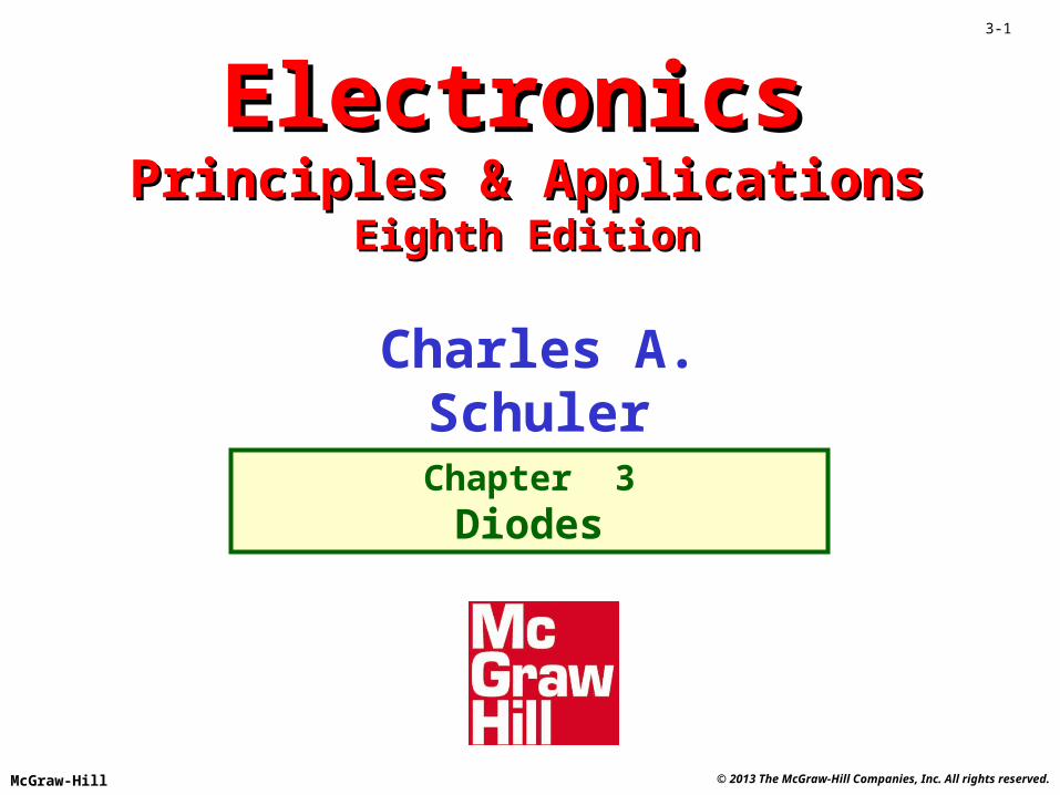
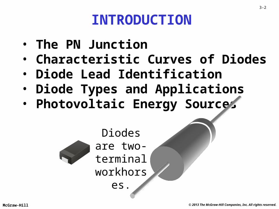
• The PN Junction• Characteristic Curves of Diodes• Diode Lead Identification• Diode Types and Applications• Photovoltaic Energy Sources
INTRODUCTION
Diodes are two-terminalworkhorses.
© 2013 The McGraw-Hill Companies, Inc. All rights reserved.McGraw-Hill
3-3
P
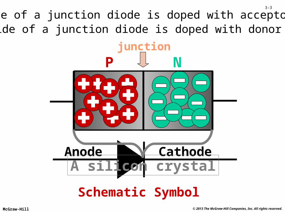
The P-side of a junction diode is doped with acceptor atoms.
N
The N-side of a junction diode is doped with donor atoms.
Schematic Symbol
CathodeAnode
junction
A silicon crystal

© 2013 The McGraw-Hill Companies, Inc. All rights reserved.McGraw-Hill
3-4
Zero Bias
Depletion region
The electrons near the junction cross over and fill the holes near the junction.
Having no carriers, the depletion region is an insulator.

© 2013 The McGraw-Hill Companies, Inc. All rights reserved.McGraw-Hill
3-5
Forward Bias
The carriers move toward the junctionand collapse the depletion region.
The diode is on (conducting).
© 2013 The McGraw-Hill Companies, Inc. All rights reserved.McGraw-Hill
3-6
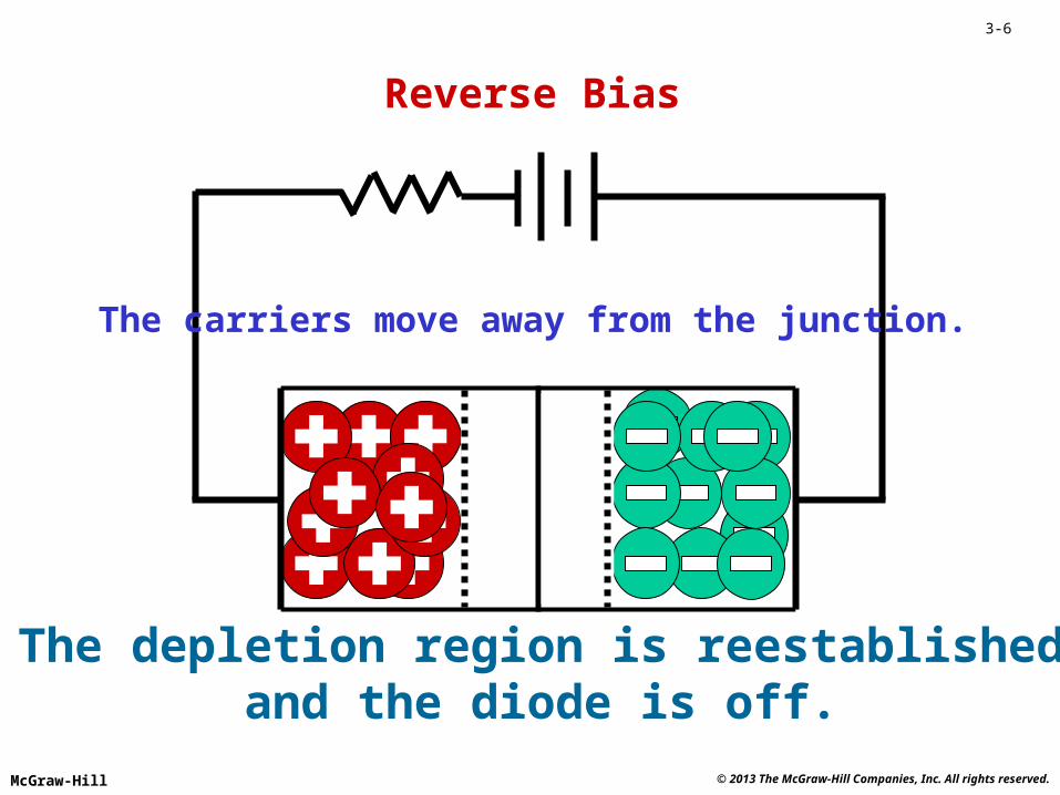
Reverse Bias
The carriers move away from the junction.
The depletion region is reestablishedand the diode is off.
© 2013 The McGraw-Hill Companies, Inc. All rights reserved.McGraw-Hill
3-7
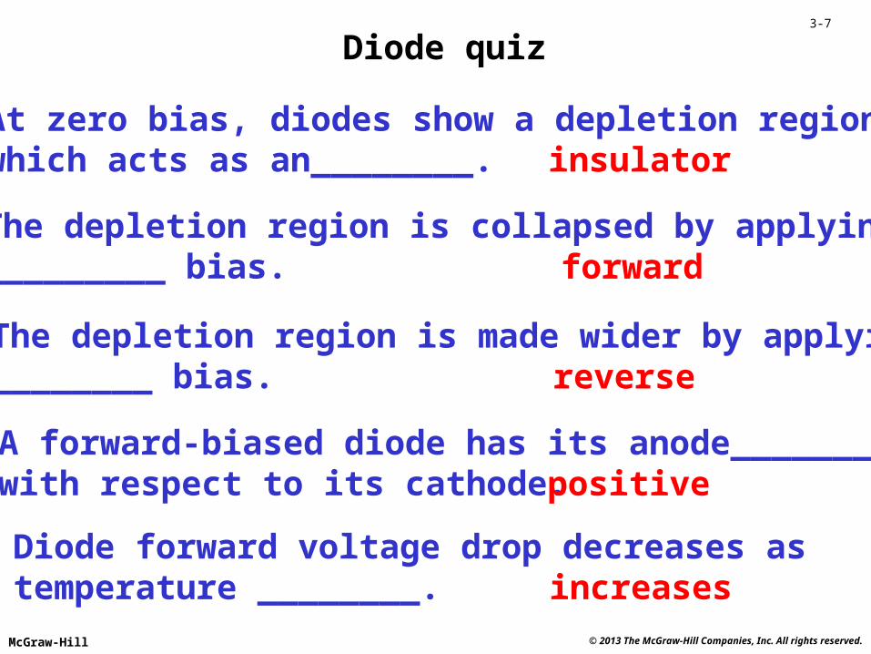
Diode quiz
At zero bias, diodes show a depletion regionwhich acts as an________. insulator
The depletion region is collapsed by applying_________ bias. forward
The depletion region is made wider by applying________ bias. reverse
A forward-biased diode has its anode________ with respect to its cathode. positive
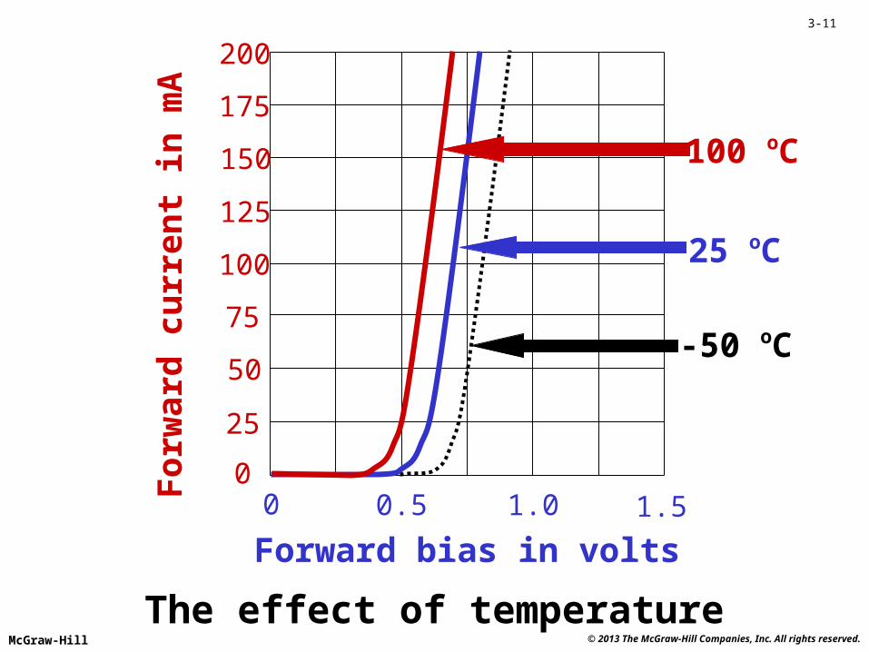
Diode forward voltage drop decreases astemperature ________. increases

© 2013 The McGraw-Hill Companies, Inc. All rights reserved.McGraw-Hill
3-8
mA
0 0.5 1.0 1.50
25
50
75
100
125
150
175
200
Volts
10 ohms
5 ohms
20 ohms
Resistor volt-ampere characteristic curves
© 2013 The McGraw-Hill Companies, Inc. All rights reserved.McGraw-Hill
3-9
For
war
d c
urr
ent
in m
A
0 0.5 1.0 1.50
25
50
75
100
125
150
175
200
Forward bias in volts
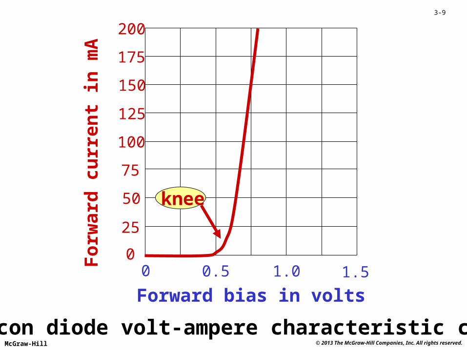
Silicon diode volt-ampere characteristic curve
knee

© 2013 The McGraw-Hill Companies, Inc. All rights reserved.McGraw-Hill
3-10
Linearity
• The volt-ampere characteristic curve for a resistor is a straight line (linear).
• A diode has a non-linear characteristic curve.
• The barrier potential produces a knee in the diode curve.
• The knee voltage is approximately 0.6 to 0.7 volts for silicon diodes.
© 2013 The McGraw-Hill Companies, Inc. All rights reserved.McGraw-Hill
3-11
For
war
d c
urr
ent
in m
A
0 0.5 1.0 1.50
25
50
75
100
125
150
175
200
Forward bias in volts
The effect of temperature
-50 oC
25 oC
100 oC

© 2013 The McGraw-Hill Companies, Inc. All rights reserved.McGraw-Hill
3-12
0200400600
20
40
60
80
100
120
140
Reverse bias in Volts
Reversecurrentin mA
Silicon diode reverse bias characteristic curve
breakdown
© 2013 The McGraw-Hill Companies, Inc. All rights reserved.McGraw-Hill
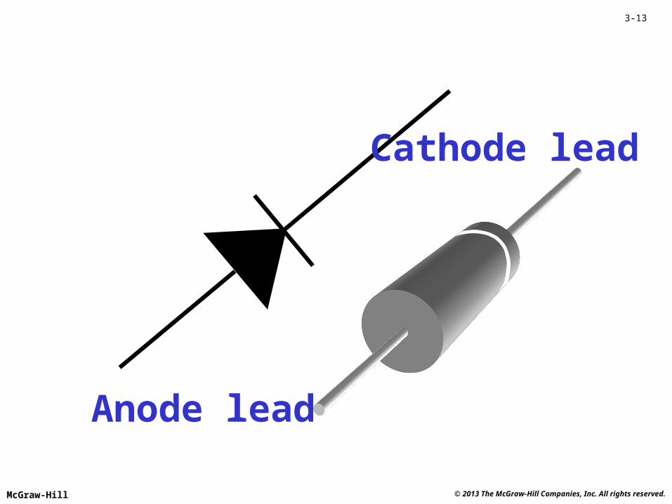
3-13
Cathode lead
Anode lead
© 2013 The McGraw-Hill Companies, Inc. All rights reserved.McGraw-Hill
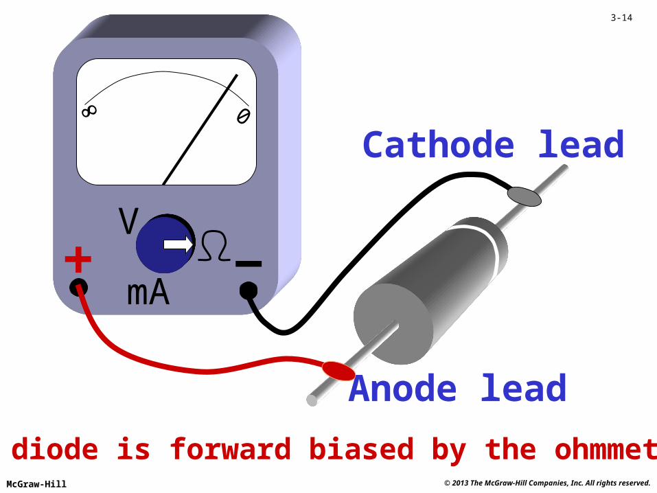
3-14
Anode lead
0
V
mA
Cathode lead
The diode is forward biased by the ohmmeter.
© 2013 The McGraw-Hill Companies, Inc. All rights reserved.McGraw-Hill
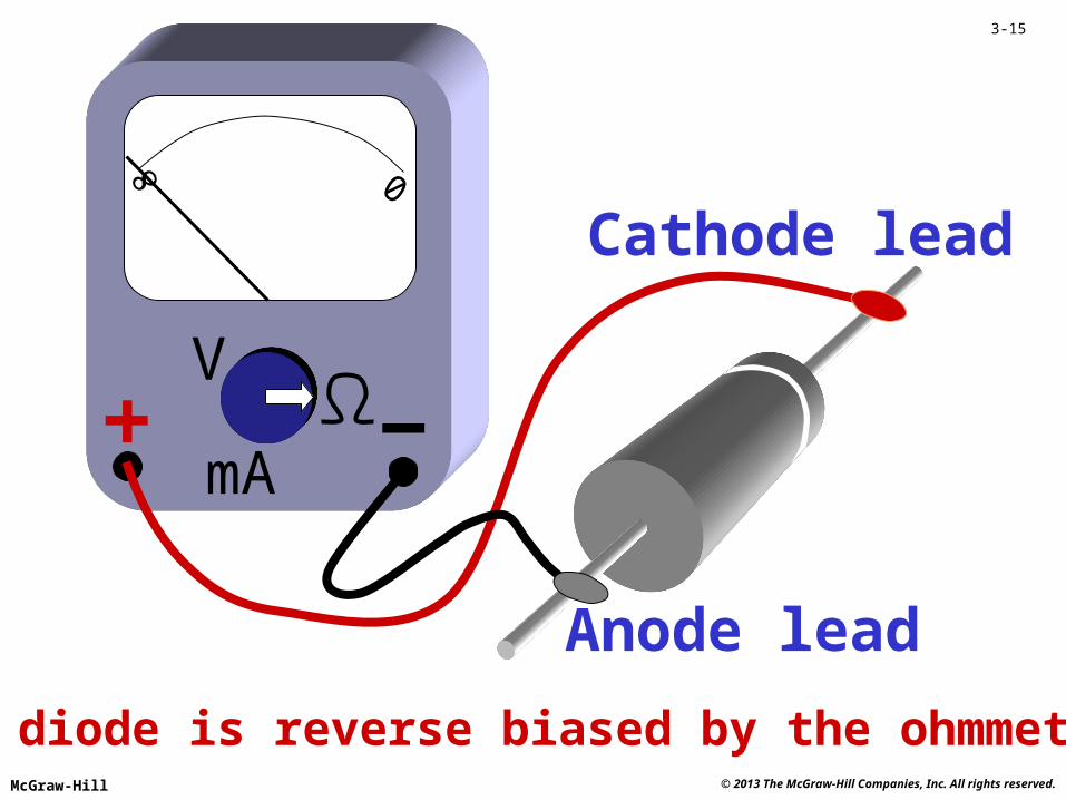
3-15
Cathode lead
Anode lead
0
The diode is reverse biased by the ohmmeter.
V
mA
© 2013 The McGraw-Hill Companies, Inc. All rights reserved.McGraw-Hill
3-16
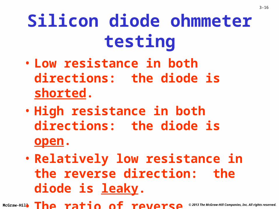
Silicon diode ohmmeter testing
• Low resistance in both directions: the diode is shorted.
• High resistance in both directions: the diode is open.
• Relatively low resistance in the reverse direction: the diode is leaky.
• The ratio of reverse resistance to forward resistance is > 1000: the diode is good.

© 2013 The McGraw-Hill Companies, Inc. All rights reserved.McGraw-Hill
3-17
0246
20
40
60
80
100
120
140
Reverse bias in Volts
Reversecurrentin mA
A zener diode is designed to break down andconduct backwards at lower voltages.
© 2013 The McGraw-Hill Companies, Inc. All rights reserved.McGraw-Hill
3-18
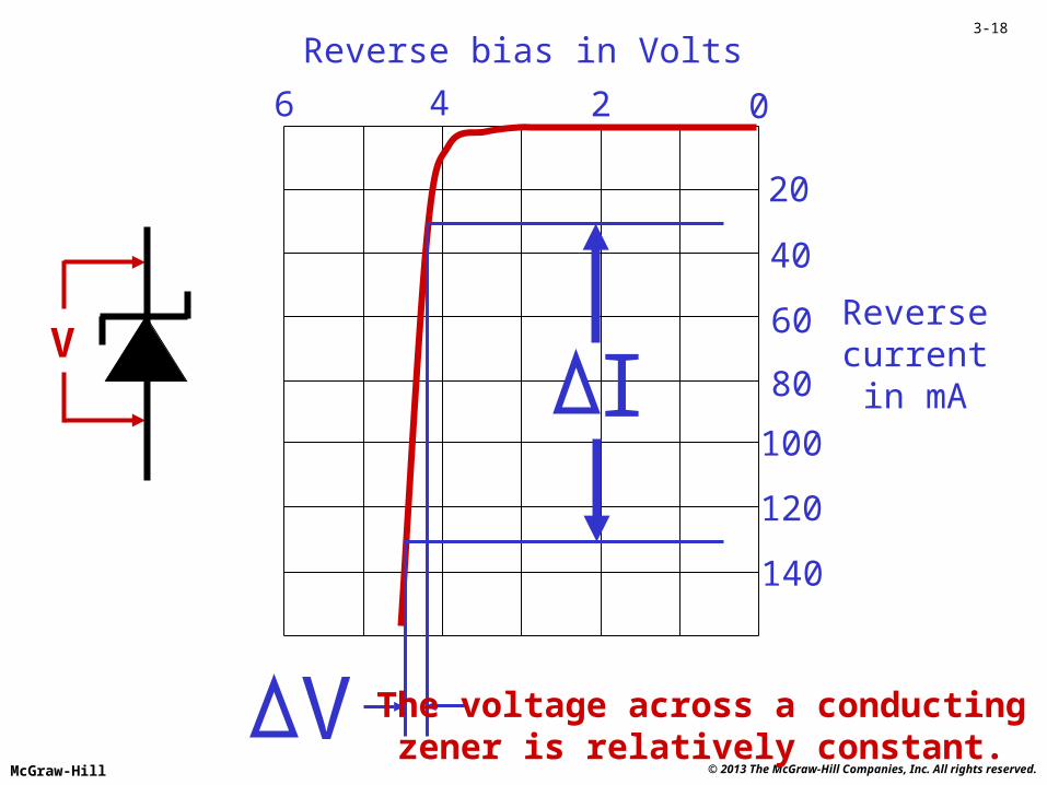
0246
20
40
60
80
100
120
140
Reverse bias in Volts
Reversecurrentin mAI
V
V
The voltage across a conductingzener is relatively constant.
© 2013 The McGraw-Hill Companies, Inc. All rights reserved.McGraw-Hill
3-19
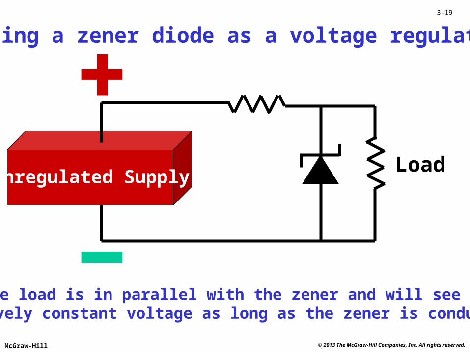
Unregulated SupplyLoad
The load is in parallel with the zener and will see a relatively constant voltage as long as the zener is conducting.
Using a zener diode as a voltage regulator
© 2013 The McGraw-Hill Companies, Inc. All rights reserved.McGraw-Hill
3-20
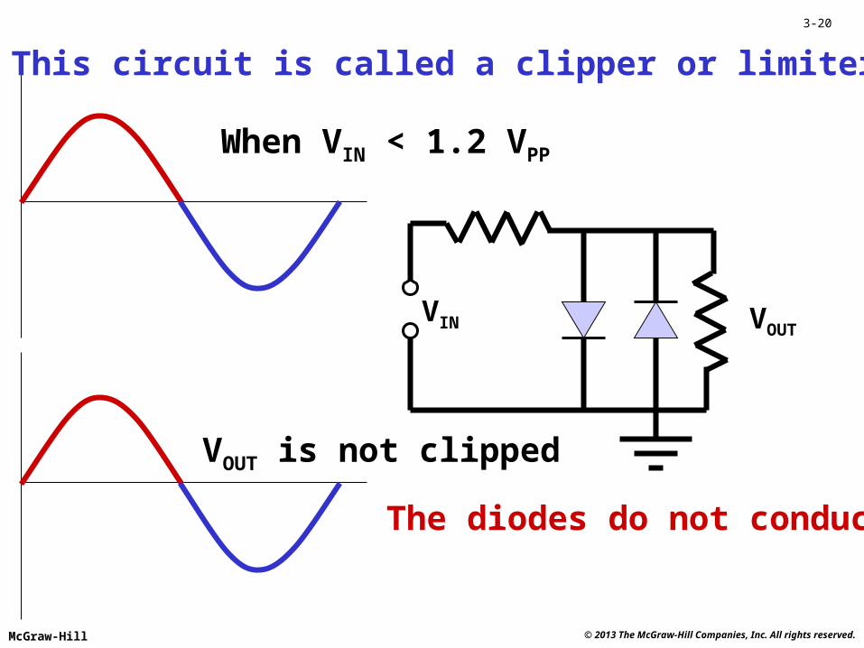
VIN VOUT
When VIN < 1.2 VPP
The diodes do not conduct.
This circuit is called a clipper or limiter.
VOUT is not clipped

© 2013 The McGraw-Hill Companies, Inc. All rights reserved.McGraw-Hill
3-21
VIN VOUT
When VIN > 1.2 VPP
+ 0.6 V
- 0.6 V
VOUT is clipped
The diodes conduct.
© 2013 The McGraw-Hill Companies, Inc. All rights reserved.McGraw-Hill
3-22
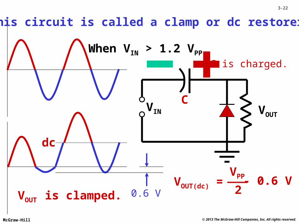
VIN VOUT
When VIN > 1.2 VPP
This circuit is called a clamp or dc restorer.
0.6 VVOUT is clamped.
dc
C is charged.
C
2VOUT(dc) =
VPP - 0.6 V
© 2013 The McGraw-Hill Companies, Inc. All rights reserved.McGraw-Hill
3-23
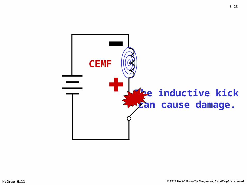
The inductive kickcan cause damage.
CEMF
© 2013 The McGraw-Hill Companies, Inc. All rights reserved.McGraw-Hill
3-24
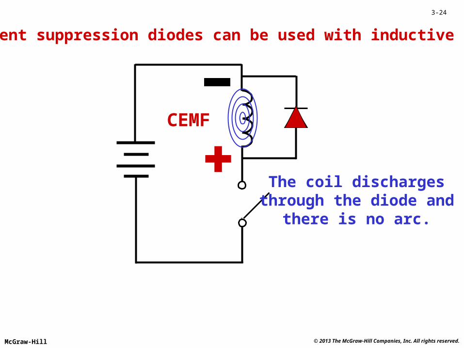
The coil dischargesthrough the diode and
there is no arc.
Transient suppression diodes can be used with inductive loads.
CEMF
© 2013 The McGraw-Hill Companies, Inc. All rights reserved.McGraw-Hill
3-25
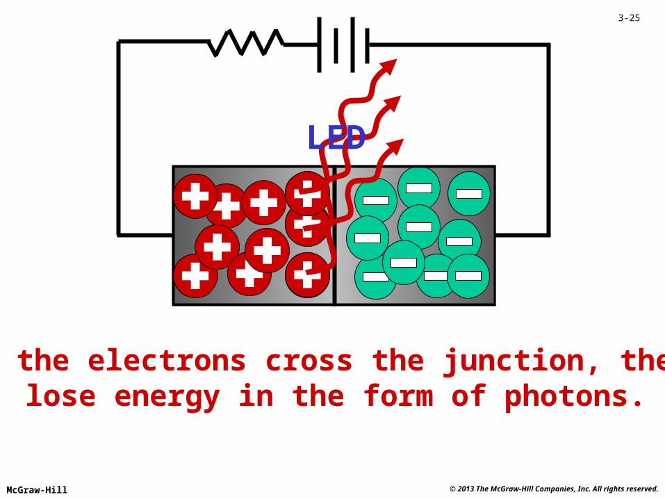
LED
As the electrons cross the junction, they lose energy in the form of photons.

© 2013 The McGraw-Hill Companies, Inc. All rights reserved.McGraw-Hill
3-26
Powersupply
VS
RS
The typical voltage drop for most LEDs is from 1.5 to 2.5 V.
LED
IS =VS - VD
RS
LED circuit
VD
© 2013 The McGraw-Hill Companies, Inc. All rights reserved.McGraw-Hill
3-27
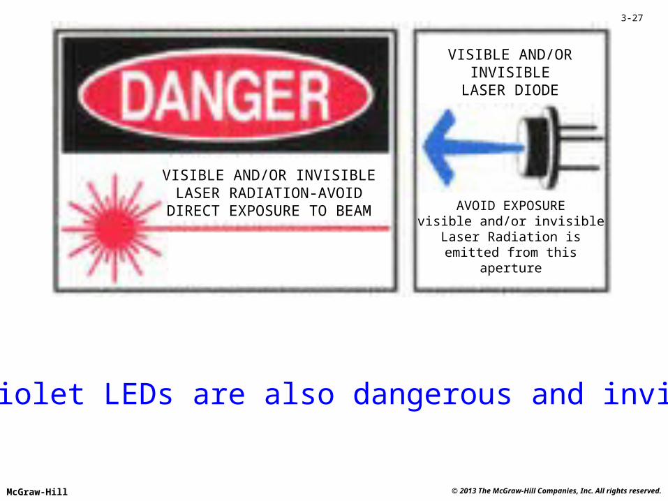
VISIBLE AND/OR INVISIBLELASER RADIATION-AVOID
DIRECT EXPOSURE TO BEAM AVOID EXPOSUREvisible and/or invisible
Laser Radiation isemitted from this
aperture
VISIBLE AND/ORINVISIBLE
LASER DIODE
Ultraviolet LEDs are also dangerous and invisible!
© 2013 The McGraw-Hill Companies, Inc. All rights reserved.McGraw-Hill
3-28
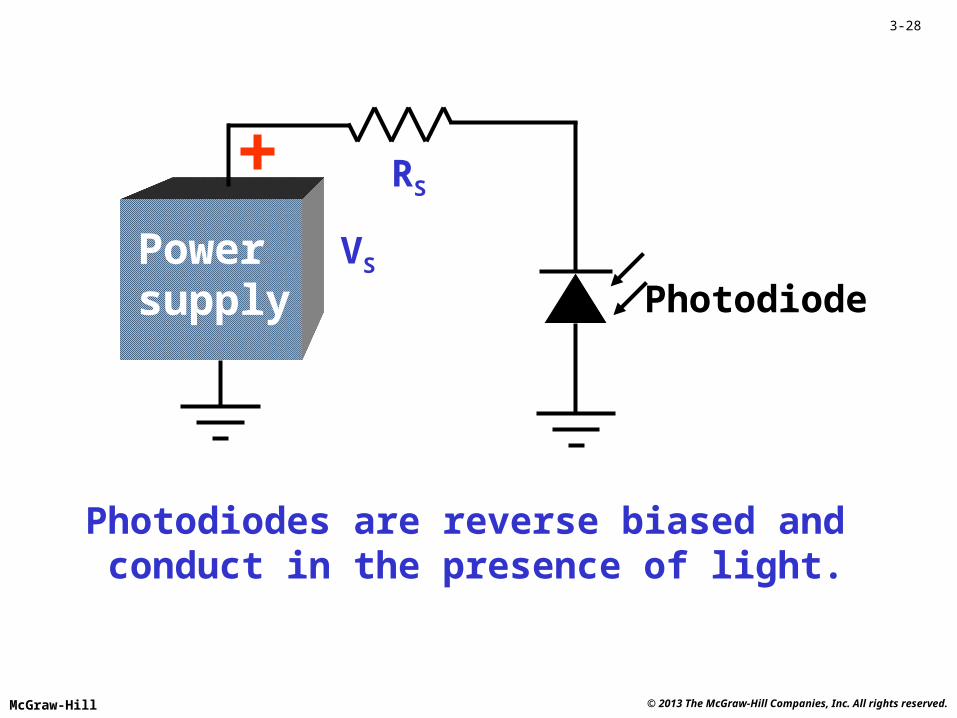
Powersupply
VS
RS
Photodiodes are reverse biased and conduct in the presence of light.
Photodiode
© 2013 The McGraw-Hill Companies, Inc. All rights reserved.McGraw-Hill
3-29
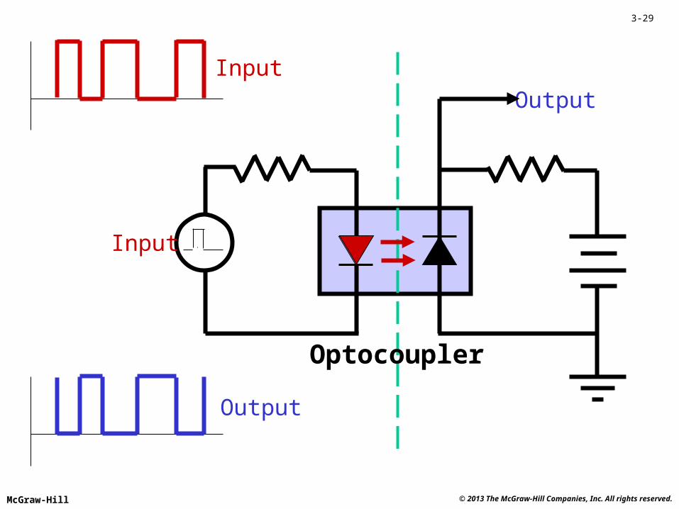
Input
Output
Input
Output
Optocoupler
© 2013 The McGraw-Hill Companies, Inc. All rights reserved.McGraw-Hill
3-30
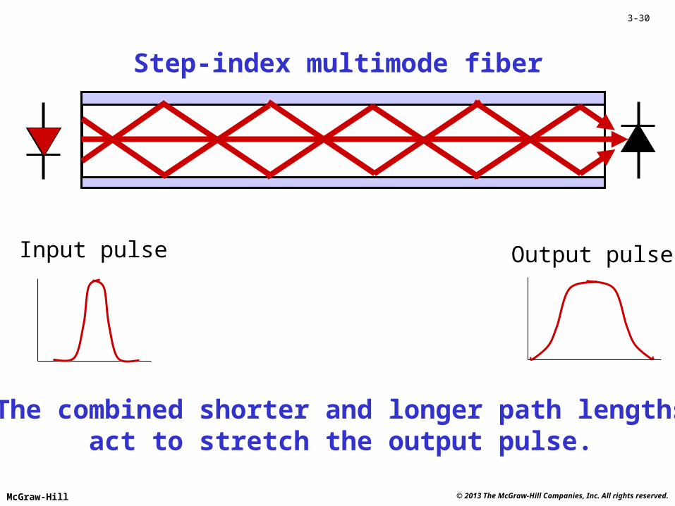
Step-index multimode fiber
Input pulse Output pulse
The combined shorter and longer path lengthsact to stretch the output pulse.
© 2013 The McGraw-Hill Companies, Inc. All rights reserved.McGraw-Hill
3-31
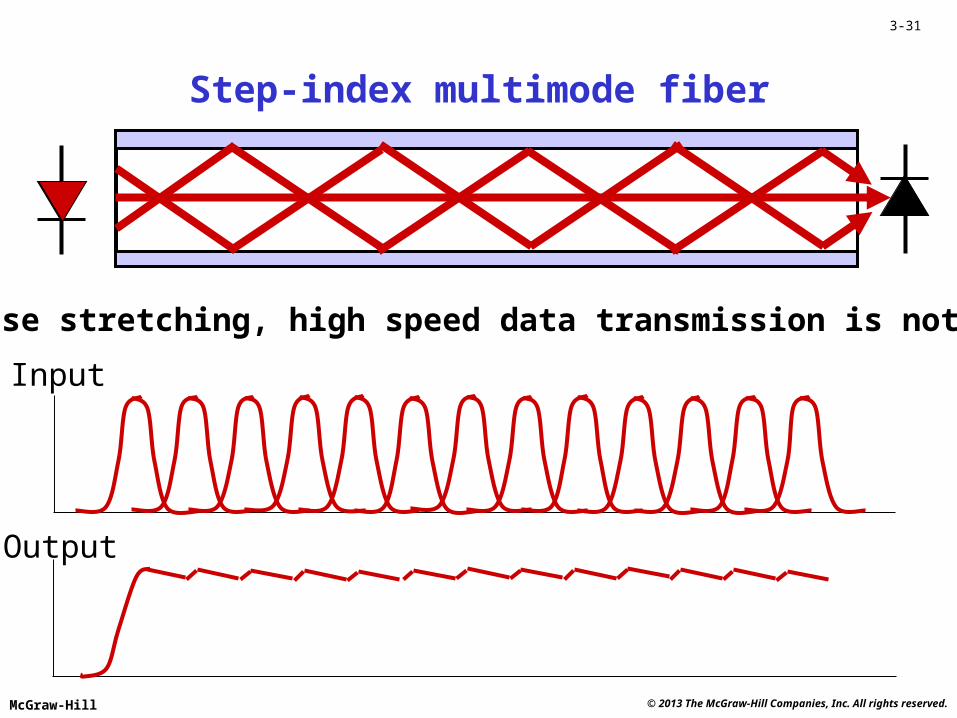
Step-index multimode fiber
Input
Output
Due to pulse stretching, high speed data transmission is not possible.
© 2013 The McGraw-Hill Companies, Inc. All rights reserved.McGraw-Hill
3-32
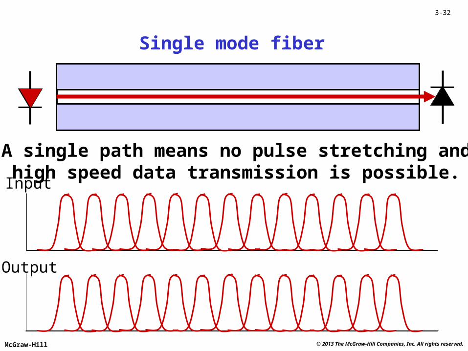
Input
Output
Single mode fiber
A single path means no pulse stretching andhigh speed data transmission is possible.
© 2013 The McGraw-Hill Companies, Inc. All rights reserved.McGraw-Hill
3-33
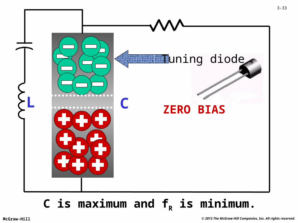
L C ZERO BIAS
C is maximum and fR is minimum.
Tuning diode

© 2013 The McGraw-Hill Companies, Inc. All rights reserved.McGraw-Hill
3-34
L C REVERSE BIAS
C is less and fR increases.
Tuning diode
© 2013 The McGraw-Hill Companies, Inc. All rights reserved.McGraw-Hill
3-35
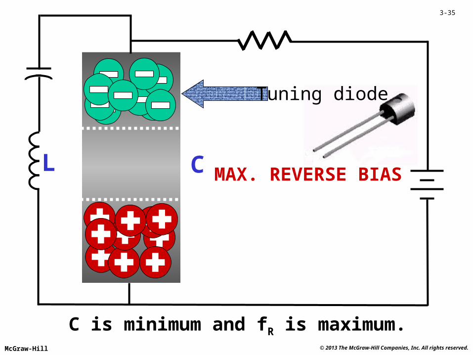
L C MAX. REVERSE BIAS
C is minimum and fR is maximum.
Tuning diode
© 2013 The McGraw-Hill Companies, Inc. All rights reserved.McGraw-Hill
3-36
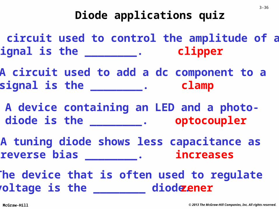
Diode applications quiz
A circuit used to control the amplitude of asignal is the ________. clipper
A circuit used to add a dc component to asignal is the ________. clamp
A device containing an LED and a photo-diode is the ________. optocoupler
A tuning diode shows less capacitance asreverse bias ________. increases
The device that is often used to regulatevoltage is the ________ diode. zener
© 2013 The McGraw-Hill Companies, Inc. All rights reserved.McGraw-Hill
3-37
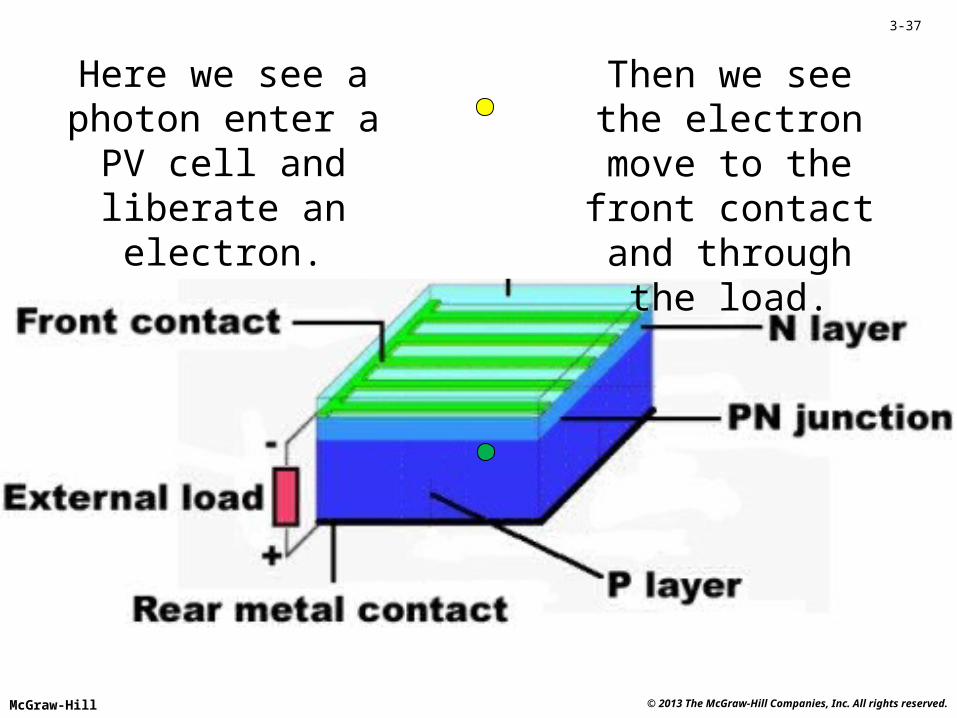
Here we see a photon enter a PV cell and liberate an electron.
Then we see the electron move to the
front contact and through the load.
© 2013 The McGraw-Hill Companies, Inc. All rights reserved.McGraw-Hill
3-38
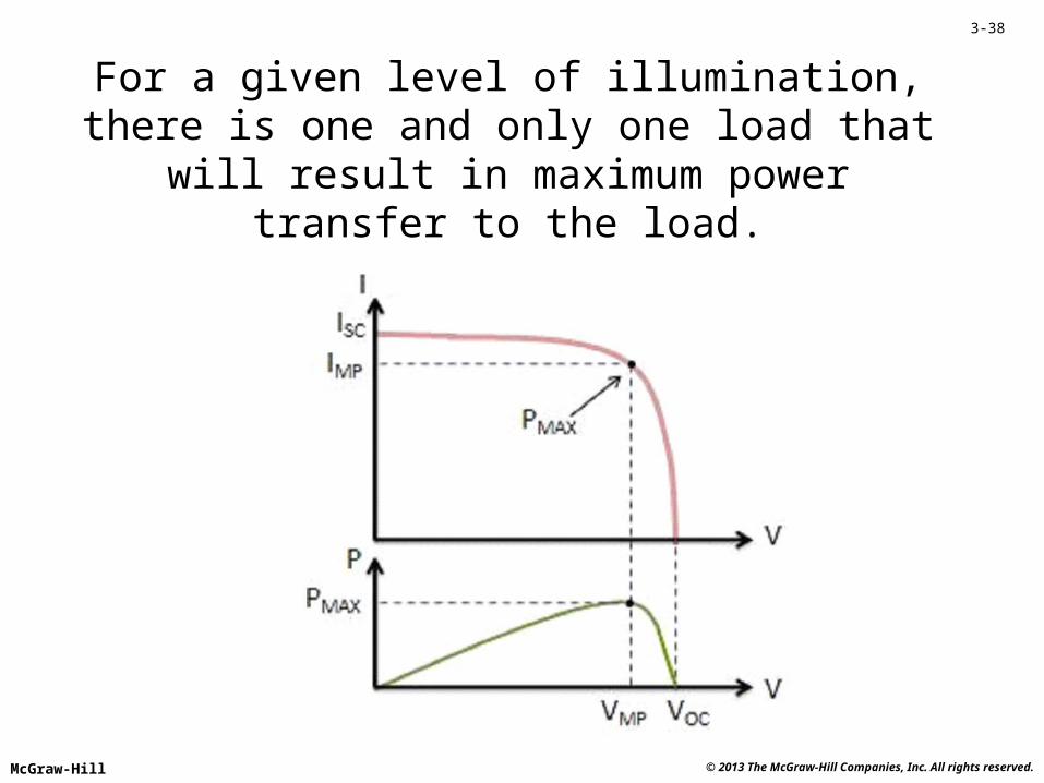
For a given level of illumination, there is one and only one load that will result in maximum power
transfer to the load.

© 2013 The McGraw-Hill Companies, Inc. All rights reserved.McGraw-Hill
3-39
The MPPT controller maintains system efficiency for varying levels of illumination.
© 2013 The McGraw-Hill Companies, Inc. All rights reserved.McGraw-Hill
3-40
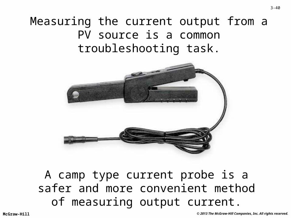
Measuring the current output from a PV source is a common troubleshooting task.
A camp type current probe is a safer and more convenient method of measuring output current.
© 2013 The McGraw-Hill Companies, Inc. All rights reserved.McGraw-Hill
3-41
Photovoltaic quiz
Photovoltaic devices directly convert light energy to ________ energy. electrical
A photon entering a PV cell might liberate a free ________. electron
The ideal (best power transfer) load on a PV source varies with the level of_______. illumination
MPPT improves PV system efficiency by adjusting the ________ resistance. load
PV troubleshooting might involve measuring the voltage and/or the ____ output. current

© 2013 The McGraw-Hill Companies, Inc. All rights reserved.McGraw-Hill
3-42
REVIEW
• The PN Junction• Characteristic Curves of Diodes• Diode Lead Identification• Diode Types and Applications• Photovoltaic Energy Sources