Embed Size (px)
Citation preview
Specialty Magnetics
Est.1968
> Specialty Magnetics 2
IntroductionThycon is known as leading manufacturer of power electronic equipment but is also recognised for its manufacture of magnetic components which are an essential part of Power Quality Management and Power Conversion.
Thycon magnetic components cover a wide range of isolating and auto transformers, tap- change transformers for manual or automatic voltage regulation, phase-shift and triplen transformers for harmonic attenuation as well as DC filter chokes, surge-limiting chokes and harmonic filter chokes.
These products serve the PQ and distribution markets from LV to MV (up to 35kV).
Three basic technologies are used, depending on application:• cast resin types• dry types• oil-filled types.
This brochure will present a summary of the products, their technologies and key applications.
TRANSFORMERSTransformers are at the centre of all power systems as distribution and power supply transformers but also for special applications such as voltage regulation and phase-shifting. The main types of transformer are described below:
Rectifier TransformersThese cover a wide range of applications as well as voltage and current ratings.
Transformers for motor-drivesMotor-drive transformers are frequently supplied as complete transformer-rectifier sets or “rectiformers” but may also be supplied as stand-alone transformers. Most rectiformers today are composed of transformers supplying uncontrolled (diode) bridges that supply, in turn, a DC link as the input to a variable-voltage, variable-frequency (VVVF) AC motor-drive with a voltage source inverter (VSI). Nevertheless, a number of DC motor drives continue to be made or upgraded and these generally consist of thyristor bridges that are also supplied for AC motor drives controlled by current source inverters (CSI). In any event, the transformer requirements are very similar except that those for controlled bridges will be designed to allow for slightly lower power factors and higher total harmonic distortion (THD).
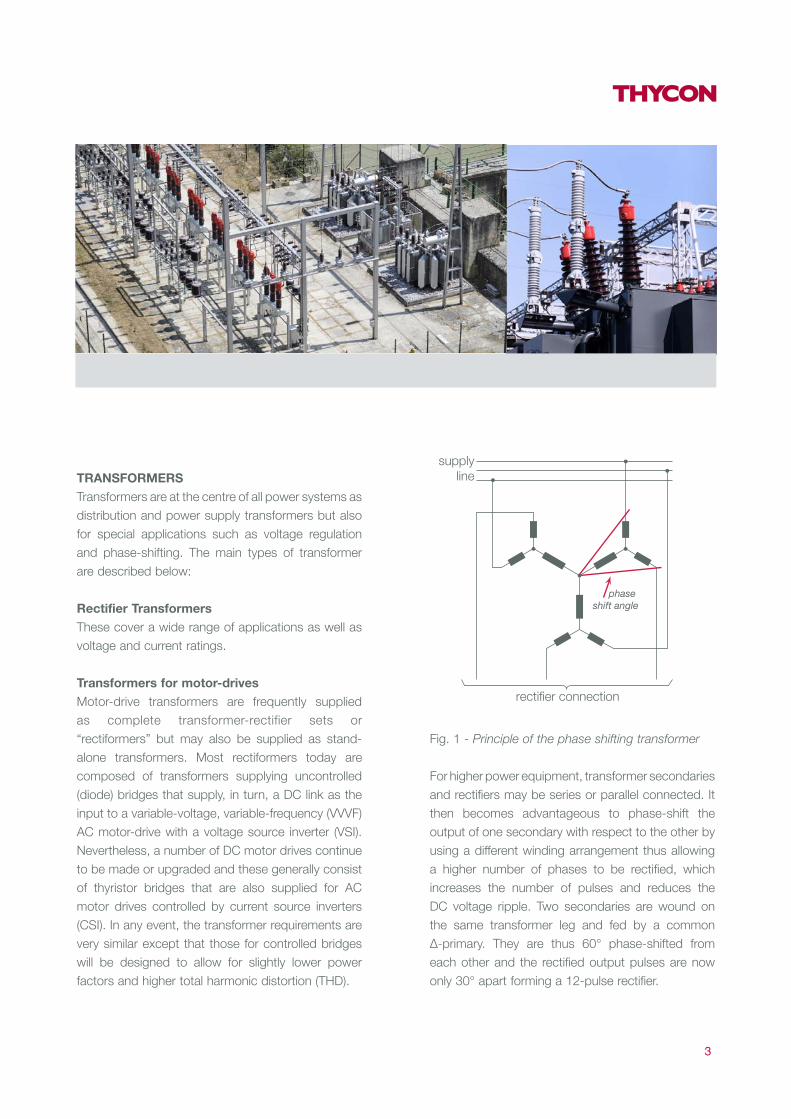
Fig. 1 - Principle of the phase shifting transformer
For higher power equipment, transformer secondaries and rectifiers may be series or parallel connected. It then becomes advantageous to phase-shift the output of one secondary with respect to the other by using a different winding arrangement thus allowing a higher number of phases to be rectified, which increases the number of pulses and reduces the DC voltage ripple. Two secondaries are wound on the same transformer leg and fed by a common Δ-primary. They are thus 60° phase-shifted from each other and the rectified output pulses are now only 30° apart forming a 12-pulse rectifier.
3
rectifier connection
phase shift angle
supplyline

Fig. 2 - 24 pulse system composed of two 12- pulse
systems fed by two zigzag transformers shifted by
+/- 7.5°
This has the object of displacing half the rectifier load as well as its associated harmonic currents, by 30° so as to reduce the resultant amplitude of any given harmonic current drawn from the supply and is an important means of reducing THD.
Application Typical rating
Current (kA) Voltage (V)
Chemical electrolysis 5 - 150 40 - 1000
Aluminium pot-line 10 - 300 < 1500
DC arc furnace 50 - 130 600 - 1200
Graphitizing furnace 20 - 120 50 - 250
Metallurgical electrolysis 5 - 100 100 - 1000
Copper refining 10 - 50 40 - 350
Fig. 3 - Typical applications and ratings for electro-
winning transformers
The principle can be extended by the use of phase shifting transformers, introducing a smaller phase-shift by using the fork connection, a series connection of two windings in Fig. 1.
If two windings are of the same magnitude, the resultant line voltage is 30° shifted with respect to the individual windings yet custom phase shifts may be created if the voltage magnitude of the two windings differ. A technique exists to create smaller phase differences and increase the number of phases as illustrated in Fig. 2 for a 24 pulse rectiformer.
> Specialty Magnetics 4
30°30°
15°

Transformers for Electro- winningElectro-winning is a crucial stage in the extraction and processing of copper, zinc and other non-ferrous metals for which optimal productivity and efficiency demands an efficient power supply. Thycon has the experience and technological expertise to meet these needs. Though in most cases, transformers are supplied complete with rectifier for these applications, they may also be supplied as standalone magnetics. The typical application ratings are shown in Fig. 3. Some of these applications require very high transformer ratings (up to 500MVA for aluminium pot-lines). This invariably requires phase-shifting techniques to achieve harmonic mitigation.
Electro-winning is usually associated with high currents for which rectifier losses become important. For these systems, the half-wave rectifier is normally favoured since the number of diodes in any given current path is one and not two. This leads to the basic configuration of Fig. 4. This circuit yields three pulses per cycle, so there is a greater output voltage ripple and each diode conducts for 120°.
Fig. 4 - Current and voltage waveforms of a three-
phase, half- wave rectifier
Fig. 5 - Two half -wave bridges phase-shifted by 180°
to cancel the DC component and restore 6-pulse
operation
5

Fig. 6 - Two half -bridges with an IPT
In this connection, the current in each arm is also the current in each secondary phase and the transformer now sees a DC current in its secondary, i.e. the transformer has a DC component in its flux, which means that a larger magnetic core is required to avoid saturation. The transformer primary does not conduct a DC current so that the primary current is a rectangular wave corresponding to the secondary current but without the DC off-set.The problem of a DC component in the flux can be avoided by using two secondary windings phase-shifted by 180°, the second winding cancelling out the DC component (see Fig. 5). The iron costs are reduced but the cost reduction is slightly off-set by having the additional cost of a second winding (of half the current rating). The 180° phase-shift also restores 6-pulse operation with its 300Hz ripple.The secondaries still conduct a DC current but the flux in the transformer core is purely AC so that the transformer iron sizing remains the same as for a full-wave rectiformer. Each diode conducts for only 60°. This means that the form-factor (FF) of the current (FF=IRMS/IAVE) is higher for the double half-wave connection than for either the full-wave or the single half-wave.
> Specialty Magnetics 6

Since diode losses have an average and an RMS component, this mode of operation would partly off-set the advantage (over the full-wave) of having current flow only through 3 diodes instead of through 6. This problem is solved by connecting the two half-bridges via a decoupling inductance (Inter-Phase Transformer or IPT) which sustains the voltage difference between the two bridges and “sucks” current for a longer period (120°) from each conducting branch. This connection is shown in Fig. 6.
The generation of extra phases through phase-shifting is increasingly attractive with higher currents and this can be equally applied to half-wave bridges using transformers with twice the secondary number of windings.
Fig. 7 - Unbalanced impedances (a) represented by
unbalanced admittances (b)
Fig. 8 - Compensation of susceptance
7
aa
a
Ia
Ib
Ic
Ia
Ib
I c
V
Vb
a
Vc
Z
Vb
a
Yca
Yab
Ybc
Zc
Zb
Vcb
b
b
cc
GabYab jBab
a
=
GabYab =
+
GabjB
ab- jBab
b

Fig. 9 - Three -phase unbalanced load of admittance
Y compensated by variable susceptances B ((C)
indicates reactive compensation)
Transformers for Traction SubstationsDC Traction voltages in Australia fall into three classes: 600, 750 and 1500VDC. The transformer connections are typically 12 pulse though the simpler configuration of 6 pulse may be considered for lower power LV installations.
AC systems (22kV/50Hz in Australia) present a particular problem in that they are supplied by a three-phase utility to power a single-phase AC load. In such cases, “load-balancing” is required in order for the single-phase load to appear at the transformer terminals as a balanced three-phase load.
It has been shown [1] that it is possible to transform the current drawn by an unbalanced and generally non- unity power‐factor load into a balanced set of line currents.
Any dissimilar three-phase load impedances, Z, can be represented by corresponding admittances, Y according to Fig. 7. An admittance such as Yab may be composed of a conductance (G) and a susceptance(B), such that:
Yab = Gab + jBab (Eqn 1)
The susceptance of Eqn 1 can be cancelled by an appropriate compensating susceptance, Bab, connected in parallel with Yab resulting in a pure conductance Gab, as illustrated in Fig. 8.
> Specialty Magnetics 8
a
b
c
V = VV = a²Vb
a
V = aVc
a
b
c
Compensator Load
Ib
Bbc
Bca
Bab
Ybc
Yca
Yab
Ic Ia Ib Ic Ia

Fig. 10 - Balancing of a single- phase resistive load by
a capacitive and an inductive susceptance
For arbitrary, time-varying, unbalanced loads, a Thycon APFR [2] can act as a variable susceptance in a delta- connected compensator according to Fig. 9.
The principle described above can be extended to any degree of imbalance and includes the rebalancing of single-phase loads connected across two of the three phases as in the case of a traction catenary supplied from a three-phase utility, shown in Fig. 10.Thus a three-phase SVC in delta connection can simultaneously correct load- balance and power-factor resulting in balanced currents and voltages and in unity PF.
Traction transformers generally require a high winding reactance of 10 – 12% to minimise the fault currents resulting from incidents on the long catenary or third rail.
This leads to PF problems which can be addressed using the Thycon Active Power Factor Regulator (APFR) [2]. The fault currents need to be limited because of the long reaction times (e.g. 100ms) of mechanical circuit breakers which lead to large fault currents and mechanical stresses on connecting cables.
A more advanced approach is the use of Thycon Solid State Breakers (SSB) which can limit a fault within 20μs, meaning the fault current barely exceeds the system maximal rating [3] which obviates the need for high winding reactance and poor PF.
Depending on the system or combination of systems chosen, the transformer impedances are matched to the determined protection and compensation methods. This is done in one design step since both magnetics and electronics are designed and built by Thycon.
9
Va a a
Vb
a
Ia
Ib
Ic
Ia
Ib
Ic
Ia
Ib
I cVc
V
Vb
a
Vc
V
Vb
a
Vc
c
b b b
c c

Fig. 11 - Distorted current in an iron-cored choke due
to saturation [4]
Inter- phase TransformersThese are essentially centre-tapped chokes used to decouple two three-pulse rectifiers enabling them to operate independently of each other thus ensuring 120° conduction for the transformer secondaries and rectifier diodes (improved FF) while allowing the load to benefit from a lower ripple. An example of their application is shown in Fig. 6.
Fig. 12 - Fourier analysis of waveform of Fig. 18 [4]
Phase- shifting TransformersThe phase shifting transformer was described previously in connection with the increase in number of phases required to reduce DC voltage ripple. They also have important applications in harmonic cancellation in both DC and AC circuits as described here.
In symmetrical AC systems, circuit non-linearities – such as the saturation of a transformer or choke or more commonly, the distortion caused by thyristor phase-control – lead to distortion of the sinusoidal line voltage. This harmonic distortion can be quantified by Fourier analysis as a spectrum of sinusoidal frequencies of odd integer multiples of the original (fundamental) frequency.
> Specialty Magnetics 10
20
10
0200 400 600 800
40
30
0
40
800.78 0.8 0.82 0.84
80
40

Harmonic SequencesFig. 11 shows a distorted choke current due to saturation and Fig. 12 shows the corresponding Fourier analysis up to the 20th harmonic (1kHz).
From Fig. 12 it can be seen that important harmonics are found at 150, 250 and 350Hz while those at 450, 550, 650, 750 and 950Hz are less significant but might nevertheless need attenuation, depending on system requirements. Clearly, all the harmonic orders are odd.
Of particular importance is the third harmonic which, in this example, has an amplitude of 50% of that of the fundamental and would require some very heavy filtering if other techniques were not available to us, namely through transformer configurations.
Fig. 13 shows distorted three-phase signals each composed of the fundamental plus a single (3rd) harmonic (top trace) compared with the three individual fundamentals and their 3rd harmonics. It is clear that the three 3rd harmonic signals are perfectly in phase and have no phase displacement (rotation). A similar analysis of the 9th, 15th, 21st etc harmonics would show that they also have no rotation and are known as “triplens” or “zero sequence” signals.
Fig. 13 - In-phase nature of triplen vectors [4]
The simplest harmonics to cancel are those of zero-sequence. They constitute a single phase current which can be shorted out in a delta winding, usually the primary.
Alternatively, a zigzag winding based on 6 windings of identical numbers of turns will have a 60° displacement between the two windings of a given phase which will cancel the 3rd harmonic voltages (as well as 9th, 15th etc. per Fig. 21) at the second terminal.
11
Phase A Fundamental and 3rd Harmonic
Phase B Fundamental and 3rd Harmonic
Phase C Fundamental and 3rd Harmonic
0
1
-1
0
1
-1
0
1
-1

However, in the case of unbalanced loads, large triplen currents may still flow in the neutral wire.
For non-Triplen Harmonic orders, knowing the harmonics’ displacement angles allows the selection of phase-shifted transformer windings to cancel or block the flow of specific harmonics.
By using smaller displacements of 30°, the 5th and 7th harmonic voltages may be cancelled within the secondary according to the following relationships:
5 x (+30°) + 30 = +180° shift for the 5th harmonic
7 x (-30) + 30 = -180° shift for the 7th harmonic
resulting in cancellation of the 5th and 7th harmonics. This can be achieved by two transformers whose secondaries are displaced by 30°.
These approaches can be applied to all the other harmonics (11th, 13th, 17th ....) though the effectiveness may diminish for the higher frequencies due to the transformer leakage reactance.
Triplen TransformersModern computers utilising switch-mode power supplies can produce very high harmonic currents, in particular the third harmonic, with content level as much as 80% or even higher. These add arithmetically in the neutral cable of the building power supply to 240% or more of the rated phase current value. As it is frequent practice to rate the neutral cable, at best, to the same value as the phase cables, and as the cable losses are proportional to the square of the current, the additional losses in the neutral conductor can be five times greater than the conductor rating. Since neutral cables are not fused or otherwise protected against overloads, thermal cable destruction and electrical fire can be the final results.
> Specialty Magnetics 12
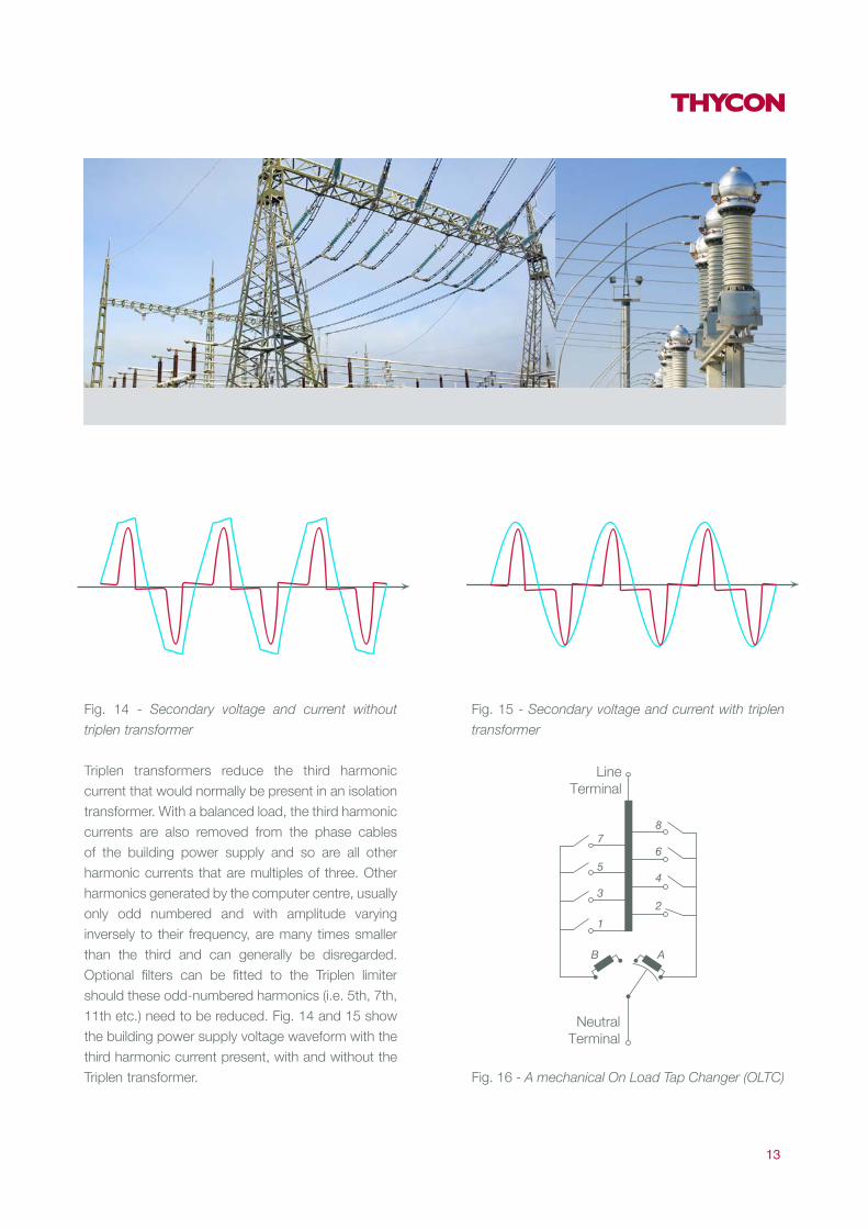
Fig. 14 - Secondary voltage and current without
triplen transformer
Triplen transformers reduce the third harmonic current that would normally be present in an isolation transformer. With a balanced load, the third harmonic currents are also removed from the phase cables of the building power supply and so are all other harmonic currents that are multiples of three. Other harmonics generated by the computer centre, usually only odd numbered and with amplitude varying inversely to their frequency, are many times smaller than the third and can generally be disregarded. Optional filters can be fitted to the Triplen limiter should these odd-numbered harmonics (i.e. 5th, 7th, 11th etc.) need to be reduced. Fig. 14 and 15 show the building power supply voltage waveform with the third harmonic current present, with and without the Triplen transformer.
Fig. 15 - Secondary voltage and current with triplen
transformer
Fig. 16 - A mechanical On Load Tap Changer (OLTC)
13
LineTerminal
NeutralTerminal
B A
87
5
3
1
6
4
2
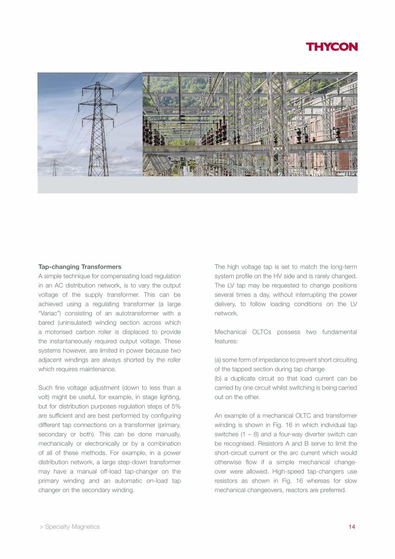
Tap- changing TransformersA simple technique for compensating load regulation in an AC distribution network, is to vary the output voltage of the supply transformer. This can be achieved using a regulating transformer (a large “Variac”) consisting of an autotransformer with a bared (uninsulated) winding section across which a motorised carbon roller is displaced to provide the instantaneously required output voltage. These systems however, are limited in power because two adjacent windings are always shorted by the roller which requires maintenance.
Such fine voltage adjustment (down to less than a volt) might be useful, for example, in stage lighting, but for distribution purposes regulation steps of 5% are sufficient and are best performed by configuring different tap connections on a transformer (primary, secondary or both). This can be done manually, mechanically or electronically or by a combination of all of these methods. For example, in a power distribution network, a large step-down transformer may have a manual off-load tap-changer on the primary winding and an automatic on-load tap changer on the secondary winding.
The high voltage tap is set to match the long-term system profile on the HV side and is rarely changed. The LV tap may be requested to change positions several times a day, without interrupting the power delivery, to follow loading conditions on the LV network.
Mechanical OLTCs possess two fundamental features:
(a) some form of impedance to prevent short circuiting of the tapped section during tap change(b) a duplicate circuit so that load current can be carried by one circuit whilst switching is being carried out on the other.
An example of a mechanical OLTC and transformer winding is shown in Fig. 16 in which individual tap switches (1 – 8) and a four-way diverter switch can be recognised. Resistors A and B serve to limit the short-circuit current or the arc current which would otherwise flow if a simple mechanical change-over were allowed. High-speed tap-changers use resistors as shown in Fig. 16 whereas for slow mechanical changeovers, reactors are preferred.
> Specialty Magnetics 14
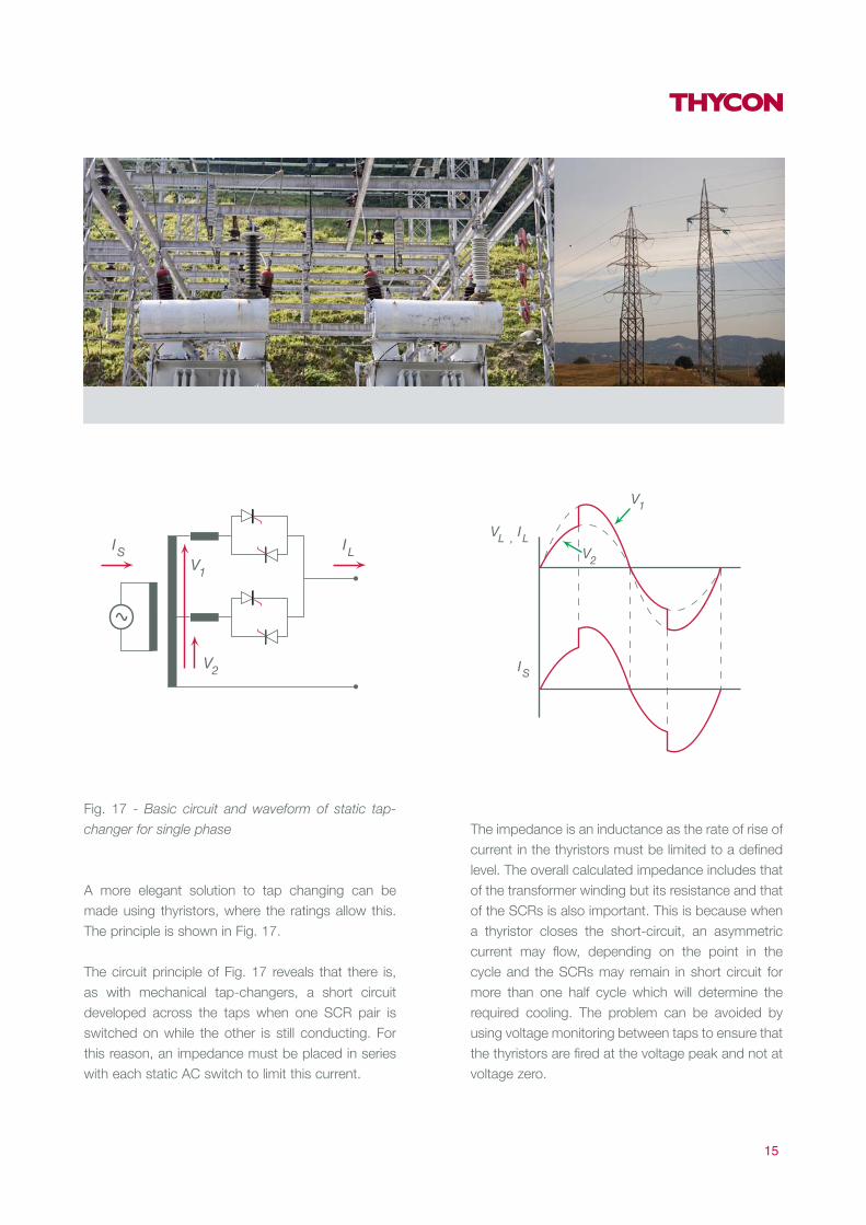
Fig. 17 - Basic circuit and waveform of static tap -
changer for single phase
A more elegant solution to tap changing can be made using thyristors, where the ratings allow this. The principle is shown in Fig. 17.
The circuit principle of Fig. 17 reveals that there is, as with mechanical tap-changers, a short circuit developed across the taps when one SCR pair is switched on while the other is still conducting. For this reason, an impedance must be placed in series with each static AC switch to limit this current.
The impedance is an inductance as the rate of rise of current in the thyristors must be limited to a defined level. The overall calculated impedance includes that of the transformer winding but its resistance and that of the SCRs is also important. This is because when a thyristor closes the short-circuit, an asymmetric current may flow, depending on the point in the cycle and the SCRs may remain in short circuit for more than one half cycle which will determine the required cooling. The problem can be avoided by using voltage monitoring between taps to ensure that the thyristors are fired at the voltage peak and not at voltage zero.
15
V2
V1
IS ILIL
IS
VL ,
V1
V2

REACTORSReactors or “chokes” are an essential part of all power and power-electronic systems. They fulfil a number of functions and require various technologies to optimally meet the diverse application needs. The main categories of reactor are described below.
VAR Compensation and Shunt ReactorsThis is a very important class of choke as static VAR compensation (SVC) is a large part of the transmission and distribution market and is also extensively used in industrial applications.
Most loads and networks are essentially inductive. Consequently, the power which flows in them contains a certain level of “reactive power” – i.e. power which does no useful work and simply generates losses.
This reactive power is the result of a phase-shift between the driving voltage of the supply and the resultant load or network current and this phase shift must be compensated, usually by the addition of capacitors.
These may be switched in as the PF varies but switching causes transients and the PF changes in steps so that the reactive load is either over or under compensated.
> Specialty Magnetics 16

Fig. 18 - Single phase equivalent representation of
power factor correction
The characteristic parameters of a transmission line are the series inductance and the shunt capacitance (due to the electrostatic field to earth). Both the inductance and the capacitance are distributed along the length of the line. When the line is loaded, there is a voltage drop along the line due to the series inductance and the series resistance. When the line is energised but not loaded (or only loaded with a small current), there is a voltage rise along the line.
To stabilise the line voltage, the line inductance can be compensated by means of series capacitors and the line capacitance to earth by shunt reactors.
Fig. 19 - Single -phase representation of the Thycon
Active Power Regulator [2]
Series capacitors are placed at different points along the line while shunt reactors are often installed in the stations at the ends of the line. In this way the voltage difference between the ends of the line is reduced both in amplitude and in phase angle. Shunt inductors for transmission systems may be fitted with tap changers to allow the shunt reactance to vary with the capacitive current.
However, most compensation systems use continual compensation and this is normally achieved using a fixed capacitor and a compensating choke regulated by an electronic controller as represented by the variable inductance of Fig. 18.
There are three methods of varying the choke’s effective value to allow continual compensation:
17
Lagging VARS(50Hz)
Leading VARS(50Hz)
Resulting VARS(leading or lagging) L f Rf

1. The Thycon APRIn this system the inductance is fed by a three-phase full-wave thyristor bridge which necessarily draws reactive power as shown in Fig. 19. The APR approach allows fast PF control, within 1.66ms. The choke is of a gapped iron-cored design for DC current and allows low iron and copper losses (low field fluctuations and current form-factor). These are usually designed for natural air-cooling.
2. The Thycon TCRFor unbalanced loads, where speed is of secondary consideration, the TCR may be used requiring AC chokes designed for high harmonic content with higher iron and copper losses. The absence of a DC component however allows for a smaller iron-core cross-section and typically requires forced air cooling.
In the TCR, the thyristors are turned on once per cycle so that compensation response is 10ms at 50Hz. TCRs are unsuitable for single-phase loads because of the high 3rd harmonic content produced by thyristor phase control.
3. Chopper Controlled ReactorVery fast response and low THD can be achieved in single-phase systems by replacing the thyristors of the line-commutated TCR by self-commutated switches in an AC chopper configuration.
This requires magnetic cores with low hysteresis losses. Such systems are advantageous in large single phase systems (mainly traction).
> Specialty Magnetics 18

Current-limiting ReactorsCurrent-limiting reactors are commonly used for fault-current protection such as may be required when inserting additional generation capacity in an existing network (renewable, co- generation etc.).
These inductors are invariably line-frequency chokes electrically and mechanically designed for surge withstand. They are typically air-cored, air-cooled AC designs.
Ideally, current-limiting reactors should have no iron circuit because iron circuits exhibit a saturating characteristic so that, under the over-current conditions which the reactor is required to protect against, there would be a tendency for the reactance to diminish.
They may be incorporated at the design stage of a network expansion, or retrofitted when protection co-ordination problems appear. The addition of a permanent reactance may require PF compensation.The need for current limitation arises from the fact that the fault capacity of pre-existing breakers may be exceeded by the addition of generating capacity. Alternative protection methods include electronic breakers which can be up to 5000 times faster than conventional breakers [3].
De -tuning and Damping ReactorsThe PFC methods discussed earlier require the shunt insertion of capacitors sized for a given compensation at line frequency. Apart from the (quantifiable) harmonics generated by the SVC equipment itself, the line may carry an undefined harmonic spectrum of various and varying amplitudes.
It is therefore possible for these harmonics to cause resonance with the PFC capacitors and line inductances resulting in very high and ultimately destructive currents to flow in the capacitors. This is avoided by the addition of “de-tuning” reactors in series with the capacitors thus defining a minimum resonance frequency below the lowest expected harmonic frequency (150, 250, 350 Hz etc in 50Hz networks). Typical “de-tuned” frequencies are 135, 190 and 215 Hz. In three-phase systems, the third harmonic is usually absent so the main harmonic of concern is the 5th for which a frequency of about 190 Hz is chosen (“tuning order” = 3.8). The series reactor serves a second important function which is that of damping the inrush currents when a capacitor bank is switched in.
19

Fig. 20 - Switched capacitor compensation showing
damping reactors L
This is particularly important for switched capacitor banks which are subject to frequent switching but any capacitor when first connected to the line will be subjected to a large inrush which can be attenuated by series L. (See Fig. 20)
Finally, though de-tuned, the reactor/capacitor combination allows a controlled attenuation of the “de-tuned” harmonic and serves as a harmonic filter while allowing a significant leading fundamental current to flow. From the foregoing it can be seen that considerable attention must be paid to the design of these reactors in view of the several functions they fulfil.
AC Reactors for Notch and THD ReductionLine-commutated equipment such as thyristor rectifiers will cause their input voltages to collapse during the commutation of line current from one branch to another. If a bridge input is the point of common coupling (PCC) for other loads, they will also see the notched voltage waveform.
Not only does the supply voltage at the PCC see the high percentage dips but these steps will cause LC networks (PF networks, surge suppression capacitors, fluorescent lighting PFC capacitors, cable capacitance and inductance, etc.) to oscillate at their resonant frequencies creating EMI which can extend into the radio spectrum.
DC ReactorsDC chokes are used as smoothing chokes in rectifier outputs, as di/dt limiting chokes for inverter inputs and as differential or common-mode filters in DC and AC supplies.
> Specialty Magnetics 20
I line
VAC
Variable PF loadContactors
CCC
LLL

Smoothing ChokesWhen inserted between the rectifier output and the bus capacitor, a DC “link” choke will smooth the DC bus voltage and reduce the AC input line harmonics.
For a conventional 6 pulse rectifier, Fig. 21 and 22 show the line voltage, line current and the DC link voltage waveforms along with a Fourier analysis of the line current without a DC link choke (L_dc = 0μH) and with a DC link choke (L_dc = 100μH). AC chokes (about 1/3 of the DC value per phase) would have a similar effect but with greater distortion and drop in input voltage.
Most smoothing chokes need to filter low frequency harmonics (50 - 300Hz). They are therefore usually of high inductance, iron cored and because of the large DC content, have large air gaps. They are typically of the dry type.
Fig. 21 - Waveforms and Fourier analysis for L_dc
= 0μH
Fig. 22 - Waveforms and Fourier analysis for L_dc =
100μH [4]
21
V_line
i_line
Volts
Amps
Volts
Vdc link
0
200
-200
0
2
-2
1000
0
500
V_line
i_line
Volts
Amps
Volts
Vdc link
0
200
-200
0
1
2
-2
0
500

Fig. 23 - IGCT-based VSI with di/dt inductance
decoupling it from the DC link
Inverter di/dt ChokesVoltage source inverters (VSI) with thyristor-based devices require a di/dt limiting choke between the inverter and the DC link to limit di/dt during device commutations, as shown in Fig. 23. (This is not necessary for most transistor-based inverters which can be controlled to self-limit di/dt.)
Capacitor CCLAMP in Fig. 23 clamps the overshoot voltage to VDC when the devices switch offand the stored energy in Ldi/dt is dissipated in resistance R.
Inverters tend to have short commutation times so the choke is only of a few micro-henries and is typically air-cored. However, being small, inverter fault currents on “shoot-through” can reach tens of kilo-amps, requiring such reactors to be of a rugged mechanical construction.
These chokes may be fitted with a secondary to allow energy feedback (rather than dissipation in R) or even with a tertiary to allow measurement of the commutation time for shoot-through detection. The construction is usually of the naturally-cooled, dry type.
> Specialty Magnetics 22
Frequency
L_dc = 0µHL_dc = 100µH
2000
4000
6000
00 200 400 600 800
R
L di/dt
S1
D1
D2 D4 D6
D3 D5
S3 S5
S2 S4 S6
Dclamp
Cclamp

TECHNOLOGIESThycon manufactures transformers and chokes using a variety of technologies including cast resin, liquid-immersed and dry types.
Liquid Immersed TypesLiquid immersed types offer the best cooling, power cycling, efficiency and dielectric integrity resulting in the highest service life, provided the fluid coolant is correctly monitored and replaced as required. Mineral oil is a common, reliable and environmentally acceptable fluid but its flammability limits its application to out-door areas where leakage or fire can be contained. Non-flammable liquids include PCBs (no longer authorised) but increasingly, silicon oils which are virtually non-flammable and environmentally safe, are also used. Thycon liquid immersed transformers use mineral or silicon oils. Reactors are seldom made of this type except for utility applications.
Cast Resin TypesCast resin types are popular in indoor applications for transformers and to some extent, reactors. The windings are made of aluminium, immersed in alkyd resin and then polymerised at 150°C. They have the advantage of being completely maintenance free with no oil, radiator or tank problems and require only simple air cooling. The completely sealed windings are impervious to damp and dust. Windings are held securely by epoxy-resin insulation along their entire lengths and require no re-pressing or adjustments even under the most severe load conditions. They are ideally suited for indoor use, especially where low acoustic noise is demanded. The resin is essentially non-inflammable. Though it can be brought to combustion at high temperatures, it is self extinguishing. For longer overloads, forced cooling is a recommended option allowing an increased rating.
23
Dry- type TransformersThough the term “dry type” also includes cast resin types, it has come to mean more specifically designs whose windings are neither immersed in oil nor embedded in resin. Though the cast resin allows a construction that is impervious to dust and humidity, the resin is a poor thermal conductor and cast resin designs tend to be larger than others. Furthermore, they are more susceptible to long thermal overloads and power cycling and are therefore better suited to constant loads. Dry types have, in general, better power cycling and overload capability than cast resin types and are the most common technology for reactors. Dry-type transformers can have their windings insulated in a number of different ways which generally allow air-flow between the coils.
Open woundThe standard dry-type transformer winding is preheated, dipped in varnish at an elevated temperature then baked to cure.
Vacuum Pressure Impregnation (VPI)This technique applies the varnish coating in alternating cycles of pressure and vacuum. The VPI process uses polyester resin. The coils are then cured in an oven. The VPI process allows better penetration of the varnish in the coils offering increased resistance to corona discharge.
Vacuum Pressure Encapsulated (VPE)With this method, several dip processes are added to encapsulate the coil assembly after which the coatings are cured in the oven allowing enhanced protection in wet environments.
MaterialsHigh permeability grain-oriented silicon steel is used as standard for most line frequency power transformers but specialty steels are used in particular cases, especially where the capitalised cost of no-load loss is high or the frequency is high (e.g. 400Hz applications for the aeronautic industry).
Both wound-strip and stamped sheet core techniques are used depending on the size and application. Most electrical windings are made using copper (Cu-ETP2 or 1).
> Specialty Magnetics 24
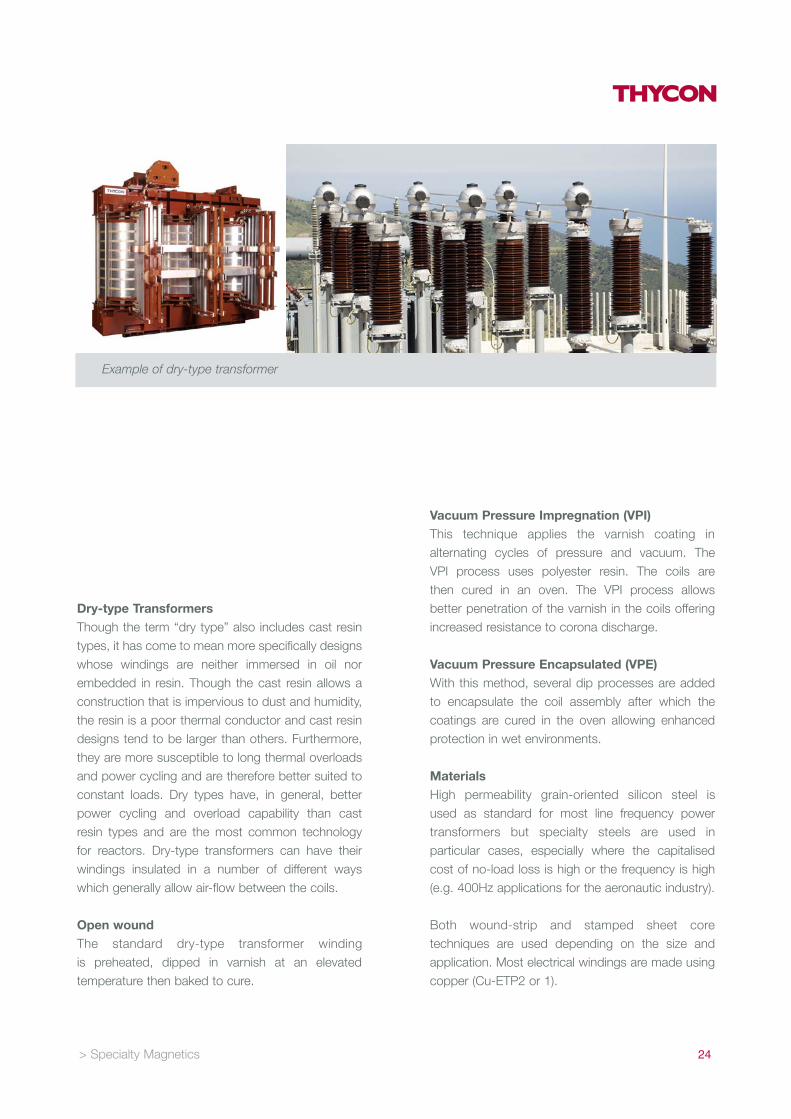
Example of dry -type transformer

Aluminium is advantageous in cast resin type transformers where the better thermal expansion coefficient match of aluminium with resin avoids cracking under power cycling. It is also used in low voltage windings of the foil-type construction.
Maintenance and ReliabilityLiquid-filled magnetics have the highest life expectancy because of the elimination of hot- spots and overall better cooling. They have a service life of 25 to 30 years. Maintenance, though greater than for dry types, is also simpler in that it only involves drawing off a sample of the fluid and analysing it for degradation or water content; operation need not be interrupted. This analysis is an accurate indication of system health. Liquid types are also easy to repair: coils may be repaired or recycled and replaced. Dry type magnetics have a shorter service life of, nevertheless, 15 to 25 years. Maintenance is important to avoid the build up of dust between the windings which impedes air flow, causes hot-spots and generally degrades cooling. Such maintenance involves service interruption and without this regular cleaning, service life may be reduced. Dry types are relatively easy to repair and recycle.
Cast resin types require little maintenance other than the cleaning of cubicle air ducts, which may not require service interruption. They are virtually impossible to repair and recycling is difficult and costlier than for other types.
SummaryAs seen from the preceding, a wide range of specialised transformers and reactors are needed to fulfil today’s power and power electronic needs. Power Electronics is now an indispensable part of Power Quality and Thycon’s 40 years of experience in both electrical and electronic power management makes it the ideal supplier for conversion and management equipment.
25

THYCON INDUSTRIAL PTY LTD
20 AUDREY AVE COBURG
3058 VIC AUSTRALIA
PH 61 3 9319 9000
FAX 61 3 9319 9001
ABN 17 068 011 049
EMAIL [email protected]
WEB www.thycon.com.au
24-HOUR SERVICE 1800 670 700
Published by Thycon