Embed Size (px)
Citation preview
77
>> Table of Contents Standard Clamping Devices
>2. Precision collets
Collets, accessories forworkpiece clamping
2.1 Deadlength collets2.2 Multi-range collets2.3 Feed fingers2.4 Clamping sleeves and clamping
sleeve holders for load-feeders2.5 Pick-up collets2.6 Guide bushes2.7 Clamping sleeves for automatic lathes2.8 Clamping levers for automatic lathes2.9 Collets, feed fingers and pick-up
collets for multi-spindle lathesClamping heads for multi-spindles
2.10 Clamping heads2.11 Draw-back collets2.12 Emergency collets, internal and
external step collets2.13 Collets for type HESK clamping
attachments2.14 Clamping sleeves with double taper2.15 Clamping sleeves with single taper
Collet chucks2.16 Type SSF lever-operated collet chucks2.17 Type KSF power-operated collet chucks2.18 Type KSKF power-operated collet chucks2.19 Type PSF power-operated collet chucks2.20 Type HESK collet clamping attachments2.21 Type HZ clamping units (hydraulic)2.22 Type HPZ high power clamping units2.23 Type NPZ – PS clamping units
(pneumatic)2.24 Sleeve mandrels
Lindenstraße 8 >> D-78583 Böttingen
Phone: +49 (0) 74 29 / 392 - 0 >> Telefax: - 11 >> www.nann.de >> [email protected] >> 08 / 200777
Lindenstraße 8 >> D-78583 Böttingen
Phone: +49 (0) 74 29 / 392 - 0 >> Telefax: - 11 >> www.nann.de >> [email protected] >> 08 / 200778
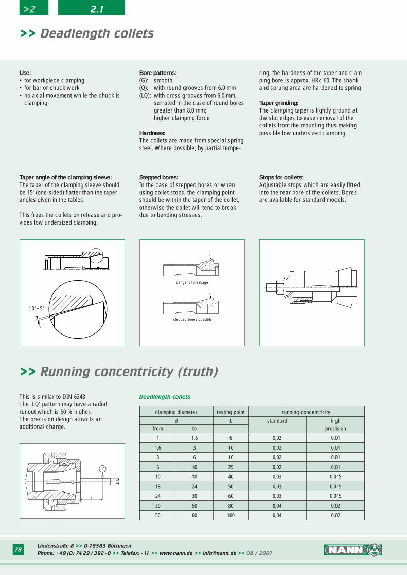
Stops for collets:Adjustable stops which are easily fittedinto the rear bore of the collets. Boresare available for standard models.
>> Deadlength collets
stepped bores possible
danger of breakage
L
ø d
10'+5'
ring, the hardness of the taper and clam-ping bore is approx. HRc 60. The shankand sprung area are hardened to spring
Taper grinding: The clamping taper is lightly ground atthe slot edges to ease removal of thecollets from the mounting thus makingpossible low undersized clamping.
Use:• for workpiece clamping• for bar or chuck work• no axial movement while the chuck is
clamping
Taper angle of the clamping sleeve:The taper of the clamping sleeve shouldbe 15' (one-sided) flatter than the taperangles given in the tables.
This frees the collets on release and pro-vides low undersized clamping.
Stepped bores:In the case of stepped bores or whenusing collet stops, the clamping pointshould be within the taper of the collet,otherwise the collet will tend to breakdue to bending stresses.
clamping diameter testing point running concentricity
d L standard highfrom to precision
1 1,6 6 0,02 0,01
1,6 3 10 0,02 0,01
3 6 16 0,02 0,01
6 10 25 0,02 0,01
10 18 40 0,03 0,015
18 24 50 0,03 0,015
24 30 60 0,03 0,015
30 50 80 0,04 0,02
50 60 100 0,04 0,02
Deadlength collets
>> Running concentricity (truth)
This is similar to DIN 6343The 'LQ' pattern may have a radialrunout which is 50 % higher.The precision design attracts an additional charge.
>2 2.1
Bore patterns:(G): smooth(Q): with round grooves from 6.0 mm(LQ): with cross grooves from 6.0 mm,
serrated in the case of round boresgreater than 8.0 mm;higher clamping force
Hardness:The collets are made from special springsteel. Where possible, by partial tempe-
Lindenstraße 8 >> D-78583 Böttingen
Phone: +49 (0) 74 29 / 392 - 0 >> Telefax: - 11 >> www.nann.de >> [email protected] >> 08 / 200779
>> Deadlength collets
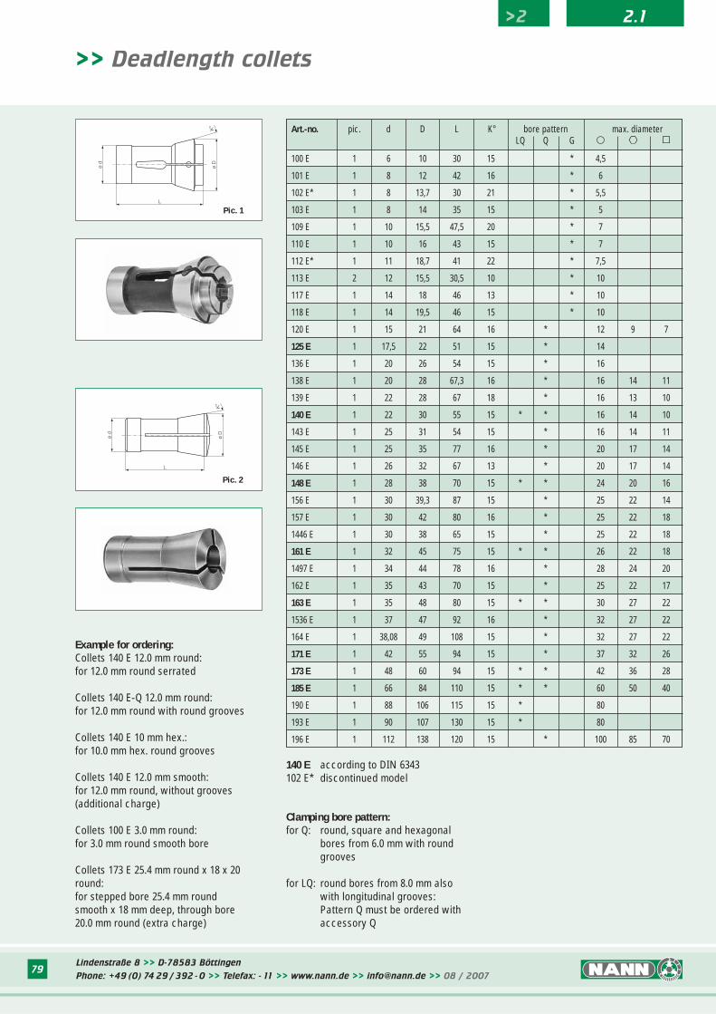
140 E according to DIN 6343102 E* discontinued model
ø d
ø D
K°
L
ø d
L
ø D
K°
Pic. 2
Pic. 1
Example for ordering:Collets 140 E 12.0 mm round:for 12.0 mm round serrated
Collets 140 E-Q 12.0 mm round:for 12.0 mm round with round grooves
Collets 140 E 10 mm hex.:for 10.0 mm hex. round grooves
Collets 140 E 12.0 mm smooth:for 12.0 mm round, without grooves(additional charge)
Collets 100 E 3.0 mm round:for 3.0 mm round smooth bore
Collets 173 E 25.4 mm round x 18 x 20round:for stepped bore 25.4 mm roundsmooth x 18 mm deep, through bore20.0 mm round (extra charge)
Clamping bore pattern:for Q: round, square and hexagonal
bores from 6.0 mm with round grooves
for LQ: round bores from 8.0 mm also with longitudinal grooves:Pattern Q must be ordered with accessory Q
Art.-no. pic. d D L K° bore pattern max. diameterLQ Q G � ºº ∫∫
100 E 1 6 10 30 15 * 4,5
101 E 1 8 12 42 16 * 6
102 E* 1 8 13,7 30 21 * 5,5
103 E 1 8 14 35 15 * 5
109 E 1 10 15,5 47,5 20 * 7
110 E 1 10 16 43 15 * 7
112 E* 1 11 18,7 41 22 * 7,5
113 E 2 12 15,5 30,5 10 * 10
117 E 1 14 18 46 13 * 10
118 E 1 14 19,5 46 15 * 10
120 E 1 15 21 64 16 * 12 9 7
125 E 1 17,5 22 51 15 * 14
136 E 1 20 26 54 15 * 16
138 E 1 20 28 67,3 16 * 16 14 11
139 E 1 22 28 67 18 * 16 13 10
140 E 1 22 30 55 15 * * 16 14 10
143 E 1 25 31 54 15 * 16 14 11
145 E 1 25 35 77 16 * 20 17 14
146 E 1 26 32 67 13 * 20 17 14
148 E 1 28 38 70 15 * * 24 20 16
156 E 1 30 39,3 87 15 * 25 22 14
157 E 1 30 42 80 16 * 25 22 18
1446 E 1 30 38 65 15 * 25 22 18
161 E 1 32 45 75 15 * * 26 22 18
1497 E 1 34 44 78 16 * 28 24 20
162 E 1 35 43 70 15 * 25 22 17
163 E 1 35 48 80 15 * * 30 27 22
1536 E 1 37 47 92 16 * 32 27 22
164 E 1 38,08 49 108 15 * 32 27 22
171 E 1 42 55 94 15 * 37 32 26
173 E 1 48 60 94 15 * * 42 36 28
185 E 1 66 84 110 15 * * 60 50 40
190 E 1 88 106 115 15 * 80
193 E 1 90 107 130 15 * 80
196 E 1 112 138 120 15 * 100 85 70
>2 2.1
Lindenstraße 8 >> D-78583 Böttingen
Phone: +49 (0) 74 29 / 392 - 0 >> Telefax: - 11 >> www.nann.de >> [email protected] >> 08 / 200780
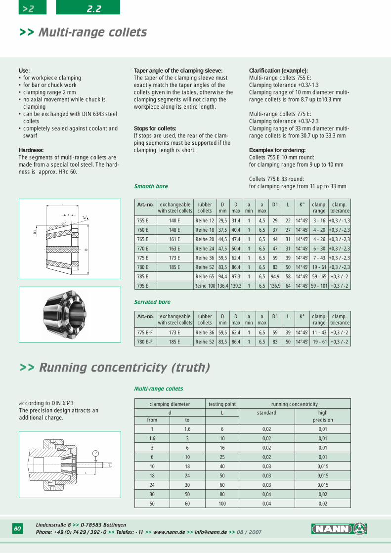
Smooth bore
Serrated bore
L
a
D
D1
K°
>> Multi-range collets
Taper angle of the clamping sleeve:The taper of the clamping sleeve mustexactly match the taper angles of thecollets given in the tables, otherwise theclamping segments will not clamp theworkpiece along its entire length.
Stops for collets:If stops are used, the rear of the clam-ping segments must be supported if theclamping length is short.
Clarification (example):Multi-range collets 755 E:Clamping tolerance +0.3/-1.3Clamping range of 10 mm diameter multi-range collets is from 8.7 up to10.3 mm
Multi-range collets 775 E:Clamping tolerance +0.3/-2.3Clamping range of 33 mm diameter multi-range collets is from 30.7 up to 33.3 mm
Examples for ordering:Collets 755 E 10 mm round:for clamping range from 9 up to 10 mm
Collets 775 E 33 round:for clamping range from 31 up to 33 mm
clamping diameter testing point running concentricity
d L standard highfrom to precision
1 1,6 6 0,02 0,01
1,6 3 10 0,02 0,01
3 6 16 0,02 0,01
6 10 25 0,02 0,01
10 18 40 0,03 0,015
18 24 50 0,03 0,015
24 30 60 0,03 0,015
30 50 80 0,04 0,02
50 60 100 0,04 0,02
Multi-range collets
L
ø d
Use:• for workpiece clamping• for bar or chuck work• clamping range 2 mm• no axial movement while chuck is
clamping• can be exchanged with DIN 6343 steel
collets• completely sealed against coolant and
swarf
Hardness:The segments of multi-range collets aremade from a special tool steel. The hard-ness is approx. HRc 60.
according to DIN 6343The precision design attracts anadditional charge.
>> Running concentricity (truth)
Art.-no. exchangeable rubber D D a a D1 L K° clamp. clamp.with steel collets collets min max min max range tolerance
755 E 140 E Reihe 12 29,5 31,4 1 4,5 29 22 14°45’ 3 - 16 +0,3 / -1,3
760 E 148 E Reihe 18 37,5 40,4 1 6,5 37 27 14°45’ 4 - 20 +0,3 / -2,3
765 E 161 E Reihe 20 44,5 47,4 1 6,5 44 31 14°45’ 4 - 26 +0,3 / -2,3
770 E 163 E Reihe 24 47,5 50,4 1 6,5 47 31 14°45’ 6 - 30 +0,3 / -2,3
775 E 173 E Reihe 36 59,5 62,4 1 6,5 59 39 14°45’ 7 - 43 +0,3 / -2,3
780 E 185 E Reihe 52 83,5 86,4 1 6,5 83 50 14°45’ 19 - 61 +0,3 / -2,3
785 E Reihe 65 94,4 97,3 1 6,5 94,9 58 14°45’ 59 - 65 +0,3 / -2
795 E Reihe 100 136,4 139,3 1 6,5 136,9 64 14°45’ 59 - 101 +0,3 / -2
>2 2.2
Art.-no. exchangeable rubber D D a a D1 L K° clamp. clamp.with steel collets collets min max min max range tolerance
775 E-F 173 E Reihe 36 59,5 62,4 1 6,5 59 39 14°45’ 11 - 43 +0,3 / -2
780 E-F 185 E Reihe 52 83,5 86,4 1 6,5 83 50 14°45’ 19 - 61 +0,3 / -2
81
Feed fingers
External feed fingers
Gd
L
L
Gø D
207 E according to DIN 6344
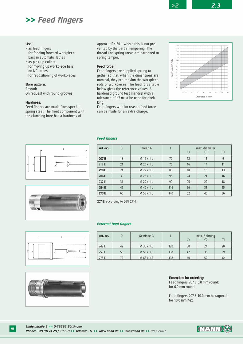
>> Feed fingers
Use:• as feed fingers
for feeding forward workpiecebars in automatic lathes
• as pick-up colletsfor moving up workpiece barson NC lathesfor repositioning of workpieces
Bore pattern: SmoothOn request with round grooves
Hardness:Feed fingers are made from specialspring steel. The front component withthe clamping bore has a hardness of
approx. HRc 60 – where this is not pre-vented by the partial tempering. Thethread and spring areas are hardened tospring temper.
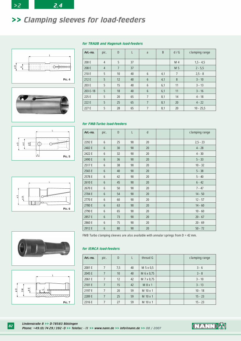
Feed force:Feed fingers are supplied sprung to-gether so that, when the dimensions arenominal, they pre-tension the workpiecerods or workpieces. The feed force tablebelow gives the reference values. Ahardened ground test mandrel with atolerance of h7 must be used for chek-king.Feed fingers with increased feed forcecan be made for an extra charge.
Art.-no. D Gewinde G L max. Bohrung� ºº ∫∫
242 E 42 M 36 x 1,5 120 30 24 20
259 E 56 M 50 x 1,5 138 42 36 29
278 E 75 M 68 x 1,5 138 60 52 42
Art.-no. D thread G L max. diameter� ºº ∫∫
207 E 18 M 16 x 1 L 70 12 11 9
217 E 21 M 20 x 1 L 70 16 14 11
220 E 24 M 22 x 1 L 85 18 16 13
236 E 30 M 28 x 1 L 95 24 21 16
237 E 31 M 29 x 1 L 90 25 22 18
254 E 42 M 40 x 1 L 116 36 31 25
273 E 60 M 58 x 1 L 140 52 45 36
Lindenstraße 8 >> D-78583 Böttingen
Phone: +49 (0) 74 29 / 392 - 0 >> Telefax: - 11 >> www.nann.de >> [email protected] >> 08 / 2007
Examples for ordering:Feed fingers 207 E 6.0 mm round:for 6.0 mm round
Feed fingers 207 E 10.0 mm hexagonal:for 10.0 mm hex
>2 2.3
Lindenstraße 8 >> D-78583 Böttingen
Phone: +49 (0) 74 29 / 392 - 0 >> Telefax: - 11 >> www.nann.de >> [email protected] >> 08 / 200782
Art.-no. pic. D L thread G clamping range
2001 E 7 7,5 40 M 5 x 0,5 3 - 6
2045 E 7 10 40 M 6 x 0,75 3 - 8
2061 E 7 12 42 M 7 x 0,75 3 - 10
2101 E 7 15 42 M 8 x 1 3 - 13
2197 E 7 20 59 M 10 x 1 10 - 18
2289 E 7 25 59 M 10 x 1 15 - 23
2316 E 7 27 59 M 10 x 1 15 - 23
Art.-no. pic. D L a B d / G clamping range
200 E 4 5 37 M 4 1,5 - 4,5
208 E 4 7 37 M 5 2 - 5,5
210 E 5 10 40 6 4,1 7 2,5 - 8
212 E 5 12 40 6 4,1 8 3 - 10
203 E 5 15 40 6 6,1 11 3 - 13
203 E-18 5 18 40 6 6,1 11 3 - 16
225 E 5 20 65 7 8,1 14 4 - 18
222 E 5 25 65 7 8,1 20 4 - 22
227 E 5 28 65 7 8,1 20 10 - 25,5
Art.-no. pic. D L d clamping range
2292 E 6 25 90 20 2,5 - 23
2402 E 6 30 90 20 4 - 28
2422 E 6 32 90 20 4 - 30
2490 E 6 36 90 20 5 - 33
2517 E 6 38 90 20 10 - 32
2565 E 6 40 90 20 5 - 38
2578 E 6 42 90 20 5 - 40
2610 E 6 45 90 20 6 - 42
2670 E 6 50 90 20 7 - 47
2704 E 6 54 90 20 14 - 50
2770 E 6 60 90 20 12 - 57
2780 E 6 63 90 20 14 - 60
2790 E 6 65 90 20 10 - 60
2857 E 6 73 90 20 20 - 67
2860 E 6 75 90 20 20 - 69
2912 E 6 80 90 20 50 - 72
for IEMCA load-feeders
for TRAUB and Hagenuk load-feeders
for FMB-Turbo load-feeders
ø D
SW ø
d
G
L
L
Gø D
Pic. 4
ø B
ø d
a
L
ø D
ø D
ø 20
L
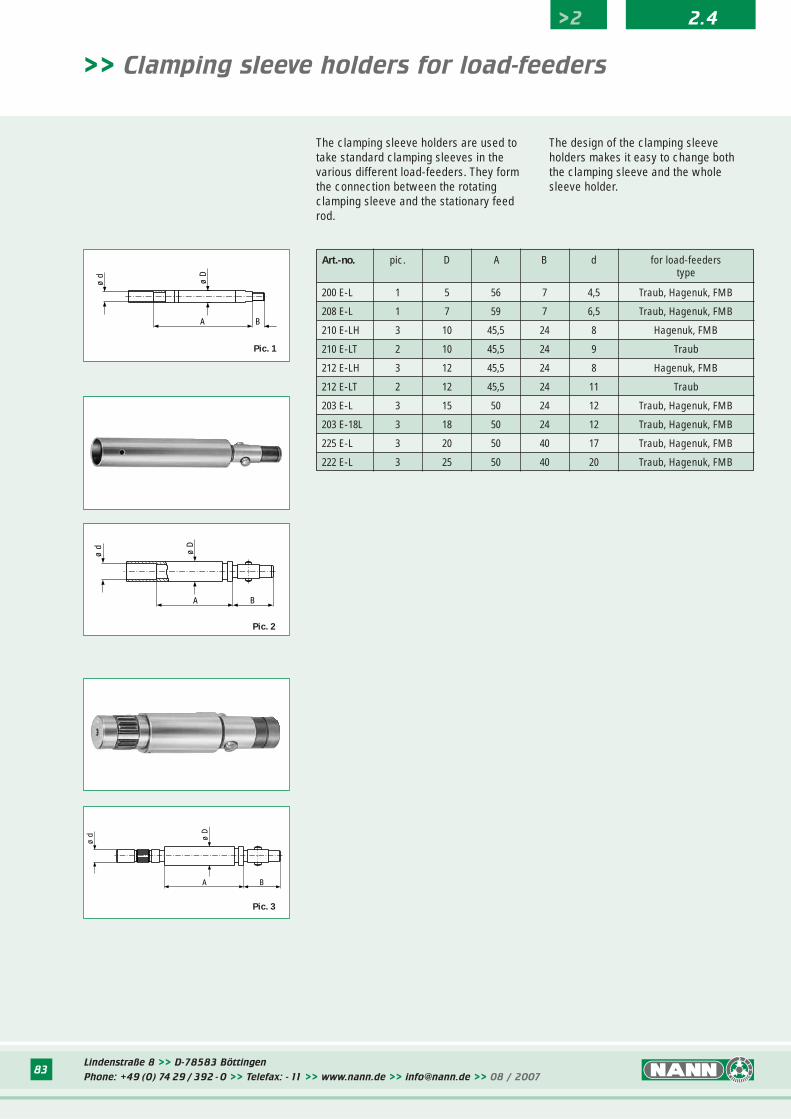
>> Clamping sleeves for load-feeders
Pic. 5
Pic. 7
Pic. 6
FMB Turbo clamping sleeves are also available with annular springs from D = 42 mm.
>2 2.4
Lindenstraße 8 >> D-78583 Böttingen
Phone: +49 (0) 74 29 / 392 - 0 >> Telefax: - 11 >> www.nann.de >> [email protected] >> 08 / 200783
Art.-no. pic. D A B d for load-feederstype
200 E-L 1 5 56 7 4,5 Traub, Hagenuk, FMB
208 E-L 1 7 59 7 6,5 Traub, Hagenuk, FMB
210 E-LH 3 10 45,5 24 8 Hagenuk, FMB
210 E-LT 2 10 45,5 24 9 Traub
212 E-LH 3 12 45,5 24 8 Hagenuk, FMB
212 E-LT 2 12 45,5 24 11 Traub
203 E-L 3 15 50 24 12 Traub, Hagenuk, FMB
203 E-18L 3 18 50 24 12 Traub, Hagenuk, FMB
225 E-L 3 20 50 40 17 Traub, Hagenuk, FMB
222 E-L 3 25 50 40 20 Traub, Hagenuk, FMB
ø D
ø d
BA
A B
ø d ø D
A B
ø D
ø d
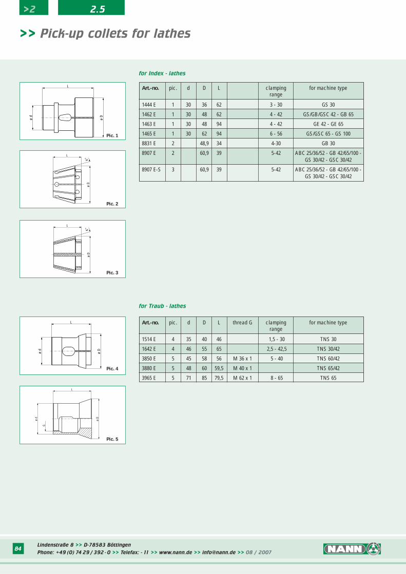
>> Clamping sleeve holders for load-feeders
Pic. 1
Pic. 2
Pic. 3
The clamping sleeve holders are used totake standard clamping sleeves in thevarious different load-feeders. They formthe connection between the rotatingclamping sleeve and the stationary feedrod.
The design of the clamping sleeve holders makes it easy to change boththe clamping sleeve and the whole sleeve holder.
>2 2.4
Lindenstraße 8 >> D-78583 Böttingen
Phone: +49 (0) 74 29 / 392 - 0 >> Telefax: - 11 >> www.nann.de >> [email protected] >> 08 / 200784
>> Pick-up collets for lathes
for Index - lathes
for Traub - lathes
ø d
ø D
L
Pic. 1
ø D
K°
L
Pic. 2
ø d
ø D
L
Pic. 4
ø D
L
ø d
G
Pic. 5
Art.-no. pic. d D L thread G clamping for machine typerange
1514 E 4 35 40 46 1,5 - 30 TNS 30
1642 E 4 46 55 65 2,5 - 42,5 TNS 30/42
3850 E 5 45 58 56 M 36 x 1 5 - 40 TNS 60/42
3880 E 5 48 60 59,5 M 40 x 1 TNS 65/42
3965 E 5 71 85 79,5 M 62 x 1 8 - 65 TNS 65
ø D
K°
L
Pic. 3
>2 2.5
Art.-no. pic. d D L clamping for machine typerange
1444 E 1 30 36 62 3 - 30 GS 30
1462 E 1 30 48 62 4 - 42 GS/GB/GSC 42 - GB 65
1463 E 1 30 48 94 4 - 42 GE 42 - GE 65
1465 E 1 30 62 94 6 - 56 GS/GSC 65 - GS 100
8831 E 2 48,9 34 4-30 GB 30
8907 E 2 60,9 39 5-42 ABC 25/36/52 - GB 42/65/100 -GS 30/42 - GSC 30/42
8907 E-S 3 60,9 39 5-42 ABC 25/36/52 - GB 42/65/100 -GS 30/42 - GSC 30/42
Lindenstraße 8 >> D-78583 Böttingen
Phone: +49 (0) 74 29 / 392 - 0 >> Telefax: - 11 >> www.nann.de >> [email protected] >> 08 / 200785
>> Guide bushes for lathes
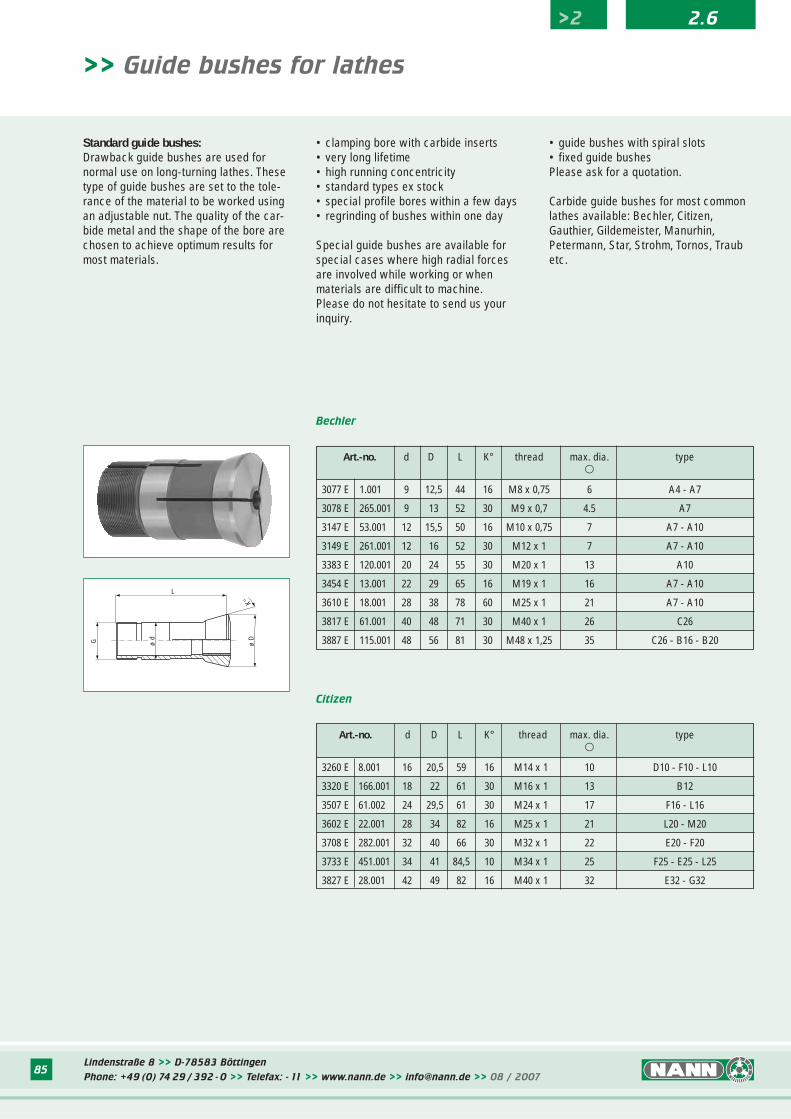
Standard guide bushes:Drawback guide bushes are used fornormal use on long-turning lathes. Thesetype of guide bushes are set to the tole-rance of the material to be worked usingan adjustable nut. The quality of the car-bide metal and the shape of the bore arechosen to achieve optimum results formost materials.
• clamping bore with carbide inserts• very long lifetime• high running concentricity• standard types ex stock• special profile bores within a few days• regrinding of bushes within one day
Special guide bushes are available forspecial cases where high radial forcesare involved while working or whenmaterials are difficult to machine.Please do not hesitate to send us yourinquiry.
• guide bushes with spiral slots• fixed guide bushesPlease ask for a quotation.
Carbide guide bushes for most commonlathes available: Bechler, Citizen,Gauthier, Gildemeister, Manurhin,Petermann, Star, Strohm, Tornos, Traubetc.
G ø d
L
ø D
K°
Bechler
Citizen
>2 2.6
Art.-no. d D L K° thread max. dia. type�
3077 E 1.001 9 12,5 44 16 M8 x 0,75 6 A4 - A7
3078 E 265.001 9 13 52 30 M9 x 0,7 4.5 A7
3147 E 53.001 12 15,5 50 16 M10 x 0,75 7 A7 - A10
3149 E 261.001 12 16 52 30 M12 x 1 7 A7 - A10
3383 E 120.001 20 24 55 30 M20 x 1 13 A10
3454 E 13.001 22 29 65 16 M19 x 1 16 A7 - A10
3610 E 18.001 28 38 78 60 M25 x 1 21 A7 - A10
3817 E 61.001 40 48 71 30 M40 x 1 26 C26
3887 E 115.001 48 56 81 30 M48 x 1,25 35 C26 - B16 - B20
Art.-no. d D L K° thread max. dia. type�
3260 E 8.001 16 20,5 59 16 M14 x 1 10 D10 - F10 - L10
3320 E 166.001 18 22 61 30 M16 x 1 13 B12
3507 E 61.002 24 29,5 61 30 M24 x 1 17 F16 - L16
3602 E 22.001 28 34 82 16 M25 x 1 21 L20 - M20
3708 E 282.001 32 40 66 30 M32 x 1 22 E20 - F20
3733 E 451.001 34 41 84,5 10 M34 x 1 25 F25 - E25 - L25
3827 E 28.001 42 49 82 16 M40 x 1 32 E32 - G32
Lindenstraße 8 >> D-78583 Böttingen
Phone: +49 (0) 74 29 / 392 - 0 >> Telefax: - 11 >> www.nann.de >> [email protected] >> 08 / 200786
>> Guide bushes for lathes
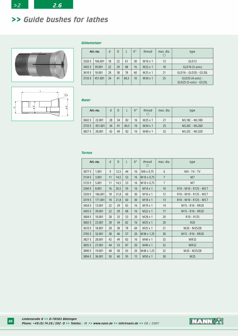
Gildemeister
Maier
Art.-no. d D L K° thread max. dia. type�
3602 E 22.001 28 34 82 16 M25 x 1 21 ML18C - ML18D
3733 E 451.001 34 41 84,5 10 M34 x 1 25 ML26C - ML26D
3827 E 28.001 42 49 82 16 M40 x 1 32 ML32C - ML32D
Tornos
G ø d
L
ø D
K°
>2 2.6
Art.-no. d D L K° thread max. dia. type�
3320 E 166.001 18 22 61 30 M16 x 1 13 GLD12
3455 E 39.001 22 29 68 16 M22 x 1 18 GLD16 (5-axis)
3610 E 18.001 28 38 78 60 M25 x 1 21 GLD16 - GLD20 - GS20L
3733 E 451.001 34 41 84,5 10 M34 x 1 25 GLD25 (4-axis) -GLD25 (5-axis) - GS25L
Art.-no. d D L K° thread max. dia. type�
3077 E 1.001 9 12,5 44 16 M8 x 0,75 6 M4 - T4 - TV
3134 E 3.001 11 14,5 53 16 M10 x 0,75 7 M7
3133 E 5.001 11 14,5 53 16 M10 x 0,75 7 M7
3260 E 8.001 16 20,5 59 16 M14 x 1 10 R10 - M10 - R125 - MS7
3320 E 166.001 18 21,8 60 30 M16 x 1 12 R10 - M10 - R125 - MS7
3319 E 171.001 18 21,8 60 30 M18 x 1 13 R10 - M10 - R125 - MS7
3454 E 13.001 22 29 65 16 M19 x 1 14 M15 - R16 - RR20
3455 E 39.001 22 29 68 16 M22 x 1 17 M15 - R16 - RR20
3604 E 10.001 28 33 53 20 M28 x 1 20 R10 - R125
3602 E 22.001 28 34 82 16 M25 x 1 20 R20
3610 E 18.001 28 38 78 60 M25 x 1 21 M20 - M25/28
3765 E 32.001 38 46 57 20 M38 x 1,25 30 M15 - R16 - RR20
3827 E 28.001 42 49 82 16 M40 x 1 32 MR32
3835 E 27.001 44 53 87 20 M40 x 1 32 MR32
3890 E 19.001 48 58 65 20 M48 x 1,25 32 M20 - M25/28
3894 E 36.001 50 60 95 15 M50 x 1 30 M25
Lindenstraße 8 >> D-78583 Böttingen
Phone: +49 (0) 74 29 / 392 - 0 >> Telefax: - 11 >> www.nann.de >> [email protected] >> 08 / 200787
Art.-no. d D L K° thread max. dia. type�
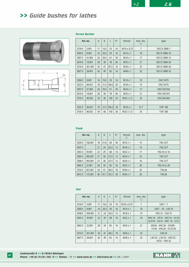
3134 E 3.001 11 14,5 53 16 M10 x 0,75 7 SW7 - 7
3260 E 8.001 16 20,5 59 16 M14 x 1 10 SW7 - 10 - JNC10
3438 E 450.001 21 24 54,5 12 M18 x 1 15 VNC12 - SNC15
3455 E 39.001 22 29 68 16 M22 x 1 18 RNC16 - SR16 - VNC16 - SA16KJR16 - SA16 - KNC 16 - Si12
3602 E 22.001 28 34 82 16 M25 x 1 21 BR20 - KNC20 - SR20R -SV20 - VNL20 - ECAS20
3733 E 451.001 34 41 84,5 10 M34 x 1 25 SNC25
3827 E 28.001 42 49 82 16 M40 x 1 32 JNC25 - JNC32 - KNC32 -SR32 - VNC32
>> Guide bushes for lathes
Tornos Bechler
Traub
G ø d
L
ø D
K°
Art.-no. d D L K° thread max. dia. type�
3134 E 3.001 11 14,5 53 16 M10 x 0,75 7 DECO 2000-7
3260 E 8.001 16 20,5 59 16 M14 x 1 10 DECO 2000-10
3507 E 61.002 24 29,5 61 30 M24 x 1 17 DECO 2000-13
3610 E 18.001 28 38 78 60 M25 x 1 21 DECO 2000-20
3733 E 451.001 34 41 87,5 10 M34 x 1 25 DECO 2000-26
3827 E 28.001 42 49 82 16 M40 x 1 32 DECO 2000-32
3260 E 8.001 16 19,5 59 16 M14 x 1 10 ENC74/75
3322 E 40.031 18 21,5 100,2 20 M18 x 1 13 ENC74/75
3507 E 61.002 24 29,5 61 30 M24 x 1 17 ENC162/164
3610 E 18.001 28 38 78 60 M25 x 1 21 ENC163/167
3735 E 40.032 34 46 150 20 M32 x 1,5 25 ENC262/264
3322 E 40.031 18 21,5 100,2 20 M18 x 1 12.7 TOP 100
3735 E 40.032 34 46 150 20 M32 x 1,5 25 TOP 200
>2 2.6
Art.-no. d D L K° thread max. dia. type�
3320 E 166.001 18 21,8 60 30 M16 x 1 13 TNL12/7
3437 E 21 24 62,5 12 M18 x 1 14 TNL12/7
3455 E 39.001 22 29 68 16 M22 x 1 17 TNL16 to 16
3585 E 492.001 27 30 57,5 12 M24 x 1 16 TNL12/7
3586 E 493.001 27 30 67,5 12 M24 x 1 16 TNL12/7
3602 E 22.001 28 34 82 16 M25 x 1 20 TNL16 to 20
3733 E 451.001 34 41 84,5 10 M34 x 1 25 TNL26
3812 E 172.001 40 47,7 65,5 30 M36 x 1 26 TNL26
Star
Lindenstraße 8 >> D-78583 Böttingen
Phone: +49 (0) 74 29 / 392 - 0 >> Telefax: - 11 >> www.nann.de >> [email protected] >> 08 / 200788
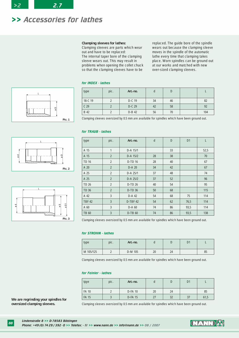
for TRAUB - lathes
for INDEX - lathes
type pic. Art.-no. d D L
18-C 19 2 D-C 19 34 46 82
C 29 2 D-C 29 42 58 92
B 42 2 D-B 42 56 70 104
ø D
L
Pic. 1
ø D
ø d
L
ø d
ø D
ø D
1
L
Clamping sleeves oversized by 0.5 mm are available for spindles which have been ground out.
Clamping sleeves oversized by 0.5 mm are available for spindles which have been ground out.
Clamping sleeves for lathes:Clamping sleeves are parts which wearout and have to be replaced:The internal taper bore of the clampingsleeve wears out. This may result inproblems when opening the collet chuckso that the clamping sleeves have to be
>> Accessories for lathes
replaced. The guide bore of the spindlewears out because the clamping sleevemoves in the spindle of the automaticlathe every time that clamping takesplace. Worn spindles can be ground outat our works and matched with newover-sized clamping sleeves.
Pic. 2
Pic. 3
for STROHM - lathes
type pic. Art.-no. d D D1 L
M 105/125 2 D-M 105 20 24 85
Clamping sleeves oversized by 0.5 mm are available for spindles which have been ground out.
for Feinler - lathes
tpye pic. Art.-no. d D D1 L
FA 10 2 D-FA 10 20 24 85
FA 15 3 D-FA 15 27 32 37 61,5
Clamping sleeves oversized by 0.5 mm are available for spindles which have been ground out.We are regrinding your spindles foroversized clamping sleeves.
>2 2.7
type pic. Art.-no. d D D1 L
A 15 1 D-A 15/1 33 52,5
A 15 2 D-A 15/2 28 38 70
TD 16 2 D-TD 16 28 40 67
A 20 2 D-A 20 34 42 67
A 25 2 D-A 25/1 37 48 74
A 25 2 D-A 25/2 37 52 96
TD 26 2 D-TD 26 40 54 95
TD 36 2 D-TD 36 50 68 115
A 42 3 D-A 42 54 68 75 114
TBF 42 3 D-TBF 42 54 62 76,5 114
A 60 3 D-A 60 74 86 93,5 114
TB 60 3 D-TB 60 74 86 93,5 138
Lindenstraße 8 >> D-78583 Böttingen
Phone: +49 (0) 74 29 / 392 - 0 >> Telefax: - 11 >> www.nann.de >> [email protected] >> 08 / 200789
for TRAUB - lathes
for STROHM - lathes
for INDEX - lathes
type pic. Art.-no. length width INDEX - no.
DG/ON/OR 3 010.010 66,1 11,8 AA 1371
12-ER 16 3 010.020 74,2 11,5 A 33280
18-25-C 19 -ER 25 -KR 30 3 010.030 74,2 13,5 A 43280
C 29 3 010.040 74,2 15,3 C 29591
24 - B 30 3 010.050 100 15,4 A 53283
36 - 52 - B 42 - B 60 3 010.060 100,1 19,9 A 73281
Clamping levers are also available for lathes type:Tornos - Petermann - Gauthier - Feinler - Manurhin - Mupem - Unamuno - Star - Citizen Gildemeister - Schütte - Pittler - Wickman
>> Clamping levers for lathes
Pic. 1
Pic. 2
Pic. 3
Pic. 4
Pic. 5
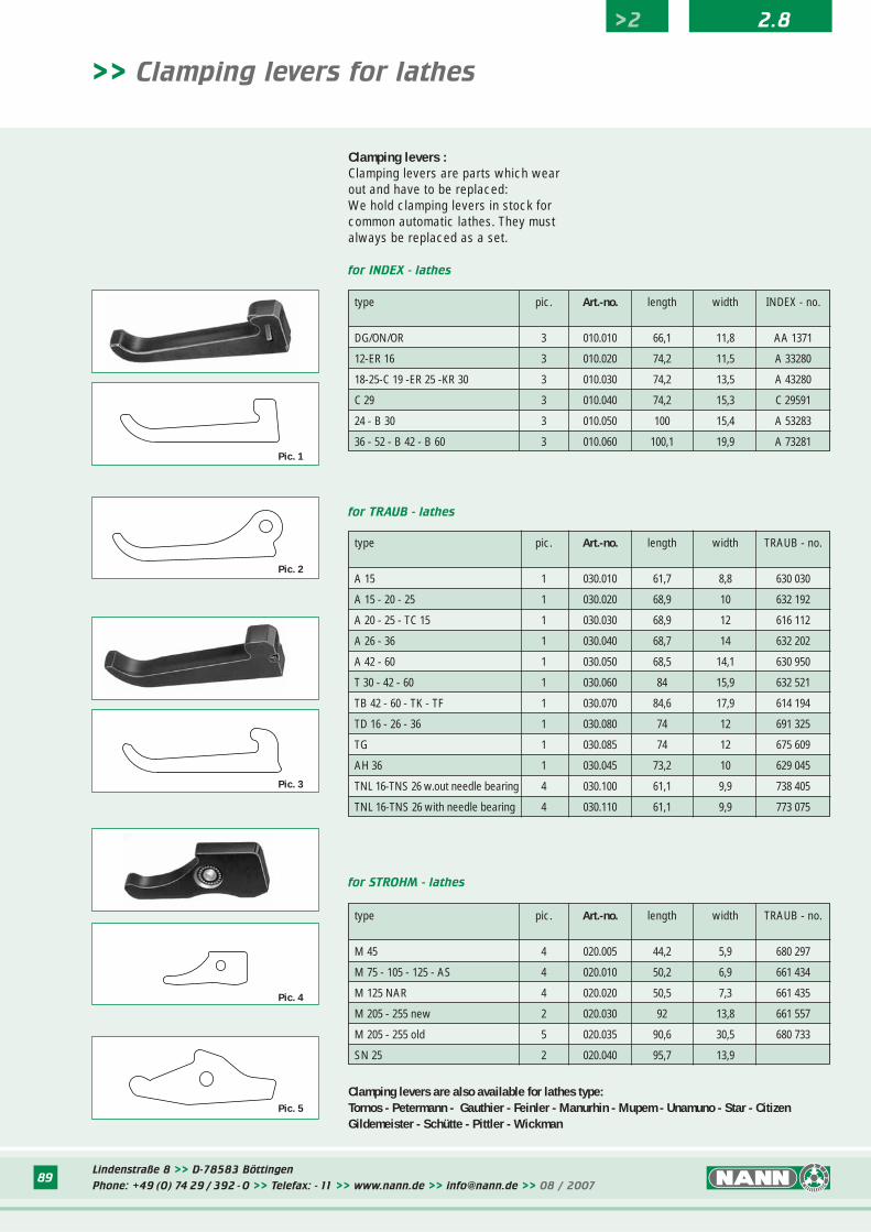
Clamping levers :Clamping levers are parts which wearout and have to be replaced:We hold clamping levers in stock forcommon automatic lathes. They mustalways be replaced as a set.
>2 2.8
type pic. Art.-no. length width TRAUB - no.
A 15 1 030.010 61,7 8,8 630 030
A 15 - 20 - 25 1 030.020 68,9 10 632 192
A 20 - 25 - TC 15 1 030.030 68,9 12 616 112
A 26 - 36 1 030.040 68,7 14 632 202
A 42 - 60 1 030.050 68,5 14,1 630 950
T 30 - 42 - 60 1 030.060 84 15,9 632 521
TB 42 - 60 - TK - TF 1 030.070 84,6 17,9 614 194
TD 16 - 26 - 36 1 030.080 74 12 691 325
TG 1 030.085 74 12 675 609
AH 36 1 030.045 73,2 10 629 045
TNL 16-TNS 26 w.out needle bearing 4 030.100 61,1 9,9 738 405
TNL 16-TNS 26 with needle bearing 4 030.110 61,1 9,9 773 075
type pic. Art.-no. length width TRAUB - no.
M 45 4 020.005 44,2 5,9 680 297
M 75 - 105 - 125 - AS 4 020.010 50,2 6,9 661 434
M 125 NAR 4 020.020 50,5 7,3 661 435
M 205 - 255 new 2 020.030 92 13,8 661 557
M 205 - 255 old 5 020.035 90,6 30,5 680 733
SN 25 2 020.040 95,7 13,9
Lindenstraße 8 >> D-78583 Böttingen
Phone: +49 (0) 74 29 / 392 - 0 >> Telefax: - 11 >> www.nann.de >> [email protected] >> 08 / 200790
>> Collets for multi-spindle automatic lathes
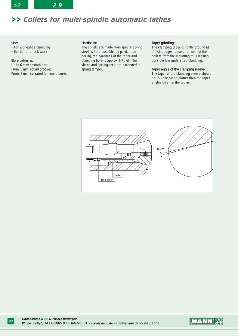
Use:• For workpiece clamping• For bar or chuck work
Bore patterns:Up to 6 mm: smooth boreFrom 6 mm: round groovesFrom 8 mm: serrated for round bores
Hardness:The collets are made from special springsteel. Where possible, by partial tem-pering, the hardness of the taper andclamping bore is approx. HRc 60. Theshank and sprung area are hardened tospring temper.
Taper grinding:The clamping taper is lightly ground atthe slot edges to ease removal of thecollets from the mounting thus makingpossible low undersized clamping.
Taper angle of the clamping sleeve:The taper of the clamping sleeve shouldbe 15' (one-sided) flatter than the taperangles given in the tables.
10'+5'
feed finger
collet
>2 2.9
Lindenstraße 8 >> D-78583 Böttingen
Phone: +49 (0) 74 29 / 392 - 0 >> Telefax: - 11 >> www.nann.de >> [email protected] >> 08 / 200791
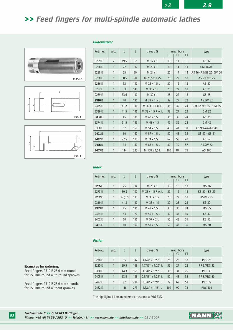
>> Feed fingers for multi-spindle automatic lathes
Use:For feeding forward workpiece bars onmulti-spindle automatic lathes.
Bore patterns:round groovessmooth bores on request
Hardness:Feed fingers are made from specialspring steel. The front component withthe clamping bore has a hardness ofapprox. HRc 60 - where this is not pre-vented by the partial tempering. Thethread and spring areas are hardened tospring temper.
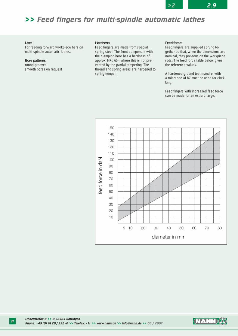
Feed force:Feed fingers are supplied sprung to-gether so that, when the dimensions arenominal, they pre-tension the workpiecerods. The feed force table below givesthe reference values.
A hardened ground test mandrel witha tolerance of h7 must be used for chek-king.
Feed fingers with increased feed forcecan be made for an extra charge.
>2 2.9
Lindenstraße 8 >> D-78583 Böttingen
Phone: +49 (0) 74 29 / 392 - 0 >> Telefax: - 11 >> www.nann.de >> [email protected] >> 08 / 200792
Pittler
Index
Gildemeister
L
Gø d
ø D
K°
Gø d
L
ø D
K°
ø D
K°
Gø d
L
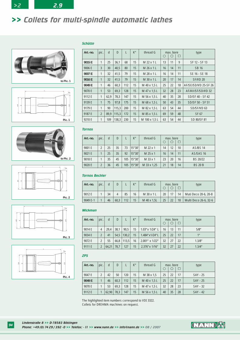
>> Collets for multi-spindle automatic lathes
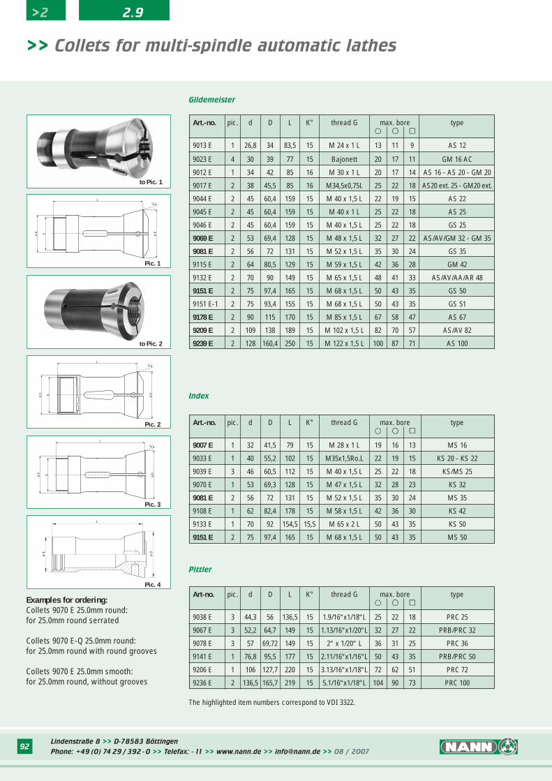
The highlighted item numbers correspond to VDI 3322.
Pic. 1
Pic. 2
Pic. 3
ø d
L
ø D
Pic. 4
Examples for ordering:Collets 9070 E 25.0mm round:for 25.0mm round serrated
Collets 9070 E-Q 25.0mm round:for 25.0mm round with round grooves
Collets 9070 E 25.0mm smooth:for 25.0mm round, without grooves
Art-no. pic. d D L K° thread G max. bore type� ºº ∫∫
9038 E 3 44,3 56 136,5 15 1.9/16“x1/18“L 25 22 18 PRC 25
9067 E 3 52,2 64,7 149 15 1.13/16“x1/20“L 32 27 22 PRB/PRC 32
9078 E 3 57 69,72 149 15 2“ x 1/20“ L 36 31 25 PRC 36
9141 E 1 76,8 95,5 177 15 2.11/16“x1/16“L 50 43 35 PRB/PRC 50
9206 E 1 106 127,7 220 15 3.13/16“x1/18“L 72 62 51 PRC 72
9236 E 2 136,5 165,7 219 15 5.1/16“x1/18“L 104 90 73 PRC 100
Art.-no. pic. d D L K° thread G max. bore type� ºº ∫∫
9007 E 1 32 41,5 79 15 M 28 x 1 L 19 16 13 MS 16
9033 E 1 40 55,2 102 15 M35x1,5Ro.L 22 19 15 KS 20 - KS 22
9039 E 3 46 60,5 112 15 M 40 x 1,5 L 25 22 18 KS/MS 25
9070 E 1 53 69,3 128 15 M 47 x 1,5 L 32 28 23 KS 32
9081 E 2 56 72 131 15 M 52 x 1,5 L 35 30 24 MS 35
9108 E 1 62 82,4 178 15 M 58 x 1,5 L 42 36 30 KS 42
9133 E 1 70 92 154,5 15,5 M 65 x 2 L 50 43 35 KS 50
9151 E 2 75 97,4 165 15 M 68 x 1,5 L 50 43 35 MS 50
>2 2.9
Art.-no. pic. d D L K° thread G max. bore type� ºº ∫∫
9013 E 1 26,8 34 83,5 15 M 24 x 1 L 13 11 9 AS 12
9023 E 4 30 39 77 15 Bajonett 20 17 11 GM 16 AC
9012 E 1 34 42 85 16 M 30 x 1 L 20 17 14 AS 16 - AS 20 - GM 20
9017 E 2 38 45,5 85 16 M34,5x0,75L 25 22 18 AS20 ext. 25 - GM20 ext.
9044 E 2 45 60,4 159 15 M 40 x 1,5 L 22 19 15 AS 22
9045 E 2 45 60,4 159 15 M 40 x 1 L 25 22 18 AS 25
9046 E 2 45 60,4 159 15 M 40 x 1,5 L 25 22 18 GS 25
9069 E 2 53 69,4 128 15 M 48 x 1,5 L 32 27 22 AS/AV/GM 32 - GM 35
9081 E 2 56 72 131 15 M 52 x 1,5 L 35 30 24 GS 35
9115 E 2 64 80,5 129 15 M 59 x 1,5 L 42 36 28 GM 42
9132 E 2 70 90 149 15 M 65 x 1,5 L 48 41 33 AS/AV/AA/AR 48
9151 E 2 75 97,4 165 15 M 68 x 1,5 L 50 43 35 GS 50
9151 E-1 2 75 93,4 155 15 M 68 x 1,5 L 50 43 35 GS 51
9178 E 2 90 115 170 15 M 85 x 1,5 L 67 58 47 AS 67
9209 E 2 109 138 189 15 M 102 x 1,5 L 82 70 57 AS/AV 82
9239 E 2 128 160,4 250 15 M 122 x 1,5 L 100 87 71 AS 100
to Pic. 1
to Pic. 2
Lindenstraße 8 >> D-78583 Böttingen
Phone: +49 (0) 74 29 / 392 - 0 >> Telefax: - 11 >> www.nann.de >> [email protected] >> 08 / 200793
Pittler
Index
Gildemeister
Gd
L
ø d
G
L
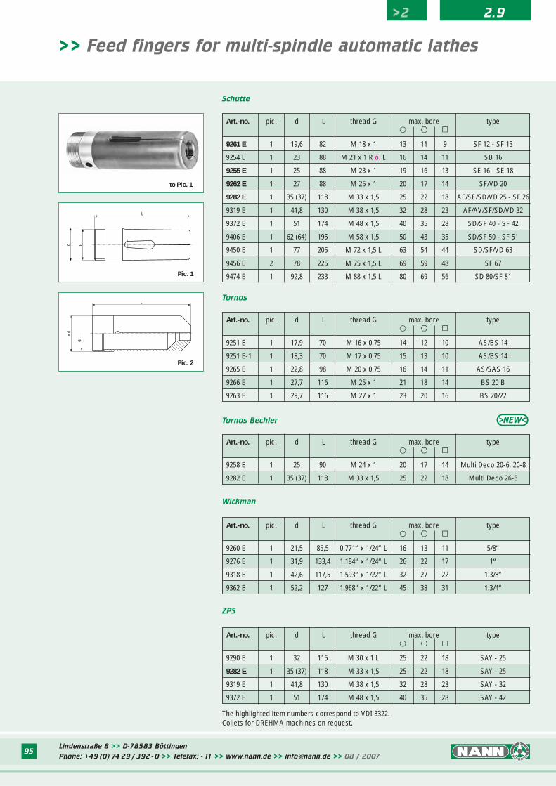
>> Feed fingers for multi-spindle automatic lathes
Pic. 1
Pic. 1
Examples for ordering:Feed fingers 9319 E 25.0 mm round:for 25.0mm round with round grooves
Feed fingers 9319 E 25.0 mm smooth:for 25.0mm round without grooves
The highlighted item numbers correspond to VDI 3322.
Art.-no. pic. d L thread G max. bore type� ºº ∫∫
9255 E 1 25 88 M 23 x 1 19 16 13 MS 16
9273 E 1 30,8 102 M 28 x 1,5 R o. L 22 19 15 KS 20 - KS 22
9282 E 1 35 (37) 118 M 33 x 1,5 25 22 18 KS/MS 25
9319 E 1 41,8 130 M 38 x 1,5 32 28 23 KS 32
9333 E 1 45 136 M 42 x 1,5 L 35 30 24 MS 35
9364 E 1 54 170 M 50 x 1,5 L 42 36 30 KS 42
9402 E 1 60 156 M 57 x 2 L 50 43 35 KS 50
9401 E 1 60 160 M 57 x 1,5 L 50 43 35 MS 50
Art-no. pic. d L thread G max. bore type� ºº ∫∫
9278 E 1 35 147 1.1/4“ x 1/20“ L 25 22 18 PRC 25
9285 E 1 39,5 168 1.7/16“ x 1/20“ L 32 27 22 PRB/PRC 32
9330 E 1 44,3 168 1.5/8“ x 1/20“ L 36 31 25 PRC 36
9405 E 1 63,5 186 2.5/16“ x 1/24“ L 50 43 35 PRB/PRC 50
9472 E 1 92 214 3.3/8“ x 1/24“ L 72 62 51 PRC 72
9482 E 1 116 273 4.3/8“ x 1/18“ L 104 90 73 PRC 100
Art.-no. pic. d L thread G max. bore type� ºº ∫∫
9259 E 2 19,5 82 M 17 x 1 13 11 9 AS 12
9268 E 1 22 86 M 20 x 1 16 14 11 GM 16 AC
9258 E 1 25 90 M 24 x 1 20 17 14 AS 16 - AS/GS 20 - GM 20
9288 E 1 30,5 90 M 28,5 x 0,75 25 22 18 AS 20 ext. 25
9286 E 1 32 140 M 28 x 1,5 L 22 19 15 AS 22
9287 E 1 33 140 M 30 x 1 L 25 22 18 AS 25
9289 E 1 33,6 140 M 30 x 1 25 22 18 GS 25
9316 E 1 40 136 M 38 X 1,5 L 32 27 22 AS/AV 32
9335 E 1 41,2 136 M 39 x 1 R o. L 35 30 24 GM 32 ext. 35 - GM 35
9336 E 1 41,5 136 M 38 x 1,5 R o. L 32 27 22 GM 32
9333 E 1 45 136 M 42 x 1,5 L 35 30 24 GS 35
9374 E 1 51,5 136 M 48 x 1,5 42 36 28 GM 42
9368 E 1 57 160 M 54 x 1,5 L 48 41 33 AS/AV/AA/AR 48
9401 E 1 60 160 M 57 x 1,5 L 50 43 35 GS 50 - GS 51
9447 E 1 77,5 170 M 74 x 1,5 L 67 58 47 AS 67
9475 E 1 94 180 M 88 x 1,5 L 82 70 57 AS/AV 82
9483 E 1 114 235 M 108 x 1,5 L 100 87 71 AS 100
>2 2.9
to Pic. 1
Lindenstraße 8 >> D-78583 Böttingen
Phone: +49 (0) 74 29 / 392 - 0 >> Telefax: - 11 >> www.nann.de >> [email protected] >> 08 / 200794
L
Gø d
ø D
K°
Schütte
Tornos
Tornos Bechler
ZPS
>> Collets for multi-spindle automatic lathes
L
Gø d
ø D
K°
Gø d
L
ø D
K°
ø D
K°
Gø d
L
Pic. 1
Pic. 2
Pic. 3
Pic. 4
The highlighted item numbers correspond to VDI 3322.Collets for DREHMA machines on request.
Art.-no. pic. d D L K° thread G max. bore type� ºº ∫∫
9015 E 1 25 36,1 68 15 M 22 x 1 L 13 11 9 SF 12 - SF 13
9006 E 3 30 40,5 80 15 M 26 x 1 L 16 14 11 SB 16
9007 E 1 32 41,5 79 15 M 28 x 1 L 16 14 11 SE 16 - SE 18
9016 E 1 32 41,5 79 15 M 30 x 1 L 20 17 14 SF/VD 20
9049 E 1 46 60,3 112 15 M 40 x 1,5 L 25 22 18 AF/SE/SD/VD 25-SF 26
9070 E 1 53 69,3 128 15 M 47 x 1,5 L 32 28 23 AF/AV/SF/SD/VD 32
9112 E 1 62,9 78,3 147 15 M 56 x 1,5 L 40 35 28 SD/SF 40 - SF 42
9139 E 1 75 97,8 175 15 M 68 x 1,5 L 50 43 35 SD/SF 50 - SF 51
9179 E 1 90 115,3 200 15 M 82 x 1,5 L 63 54 44 SD/SF/VD 63
9187 E 2 89,9 115,3 172 15 M 85 x 1,5 L 69 59 48 SF 67
9210 E 1 109 138,3 230 15 M 100 x 1,5 L 63 54 44 SD 80/SF 81
Art.-no. pic. d D L K° thread G max. bore type� ºº ∫∫
9012 E 1 34 4 85 16 M 30 x 1 L 20 17 14 Muti Deco 20-6, 20-8
9049 E-1 1 46 60,3 112 15 M 40 x 1,5L 25 22 18 Multi Deco 26-6, 32-6
Wickman
Art.-no. pic. d D L K° thread G max. bore type� ºº ∫∫
9014 E 4 29,4 38,1 90,5 15 1.03“x 1/24“ L 16 13 11 5/8“
9034 E 2 41 54,5 130,2 15 1.484“x1/24“L 25 22 17 1“
9072 E 2 55 66,8 113,5 16 2.001“ x 1/22“ 32 27 22 1.3/8“
9111 E 2 64,21 78,7 127 15 2.376“x 1/16“ 32 27 22 1.3/4“
Art.-no. pic. d D L K° thread G max. bore type� ºº ∫∫
9001 E 2 25 35 73 15°30’ M 22 x 1 14 12 10 AS/BS 14
9021 E 1 25 35 92 15°30’ M 25 x 1 16 14 11 AS/SAS 16
9018 E 1 35 45 105 15°30’ M 33 x 1 23 20 16 BS 20/22
9020 E 2 36 45 105 15°30’ M 33 x 1,25 21 18 14 BS 20 B
Art.-no. pic. d D L K° thread G max. bore type� ºº ∫∫
9047 E 2 42 50 120 15 M 38 x 1,5 25 22 17 SAY - 25
9049 E 1 46 60,3 112 15 M 40 x 1,5 L 25 22 17 SAY - 25
9070 E 1 53 69,3 128 15 M 47 x 1,5 L 32 28 23 SAY - 32
9112 E 1 62,90 78,3 147 15 M 56 x 1,5 L 40 35 28 SAY - 42
>2 2.9
to Pic. 1
to Pic. 2
Lindenstraße 8 >> D-78583 Böttingen
Phone: +49 (0) 74 29 / 392 - 0 >> Telefax: - 11 >> www.nann.de >> [email protected] >> 08 / 200795
Schütte
Tornos
Tornos Bechler
ZPS
>> Feed fingers for multi-spindle automatic lathes
Gd
L
ø d
G
L
Pic. 1
Pic. 2
The highlighted item numbers correspond to VDI 3322.Collets for DREHMA machines on request.
Art.-no. pic. d L thread G max. bore type� ºº ∫∫
9261 E 1 19,6 82 M 18 x 1 13 11 9 SF 12 - SF 13
9254 E 1 23 88 M 21 x 1 R o. L 16 14 11 SB 16
9255 E 1 25 88 M 23 x 1 19 16 13 SE 16 - SE 18
9262 E 1 27 88 M 25 x 1 20 17 14 SF/VD 20
9282 E 1 35 (37) 118 M 33 x 1,5 25 22 18 AF/SE/SD/VD 25 - SF 26
9319 E 1 41,8 130 M 38 x 1,5 32 28 23 AF/AV/SF/SD/VD 32
9372 E 1 51 174 M 48 x 1,5 40 35 28 SD/SF 40 - SF 42
9406 E 1 62 (64) 195 M 58 x 1,5 50 43 35 SD/SF 50 - SF 51
9450 E 1 77 205 M 72 x 1,5 L 63 54 44 SD/SF/VD 63
9456 E 2 78 225 M 75 x 1,5 L 69 59 48 SF 67
9474 E 1 92,8 233 M 88 x 1,5 L 80 69 56 SD 80/SF 81
Art.-no. pic. d L thread G max. bore type� ºº ∫∫
9251 E 1 17,9 70 M 16 x 0,75 14 12 10 AS/BS 14
9251 E-1 1 18,3 70 M 17 x 0,75 15 13 10 AS/BS 14
9265 E 1 22,8 98 M 20 x 0,75 16 14 11 AS/SAS 16
9266 E 1 27,7 116 M 25 x 1 21 18 14 BS 20 B
9263 E 1 29,7 116 M 27 x 1 23 20 16 BS 20/22
Art.-no. pic. d L thread G max. bore type� ºº ∫∫
9258 E 1 25 90 M 24 x 1 20 17 14 Multi Deco 20-6, 20-8
9282 E 1 35 (37) 118 M 33 x 1,5 25 22 18 Multi Deco 26-6
Wickman
Art.-no. pic. d L thread G max. bore type� ºº ∫∫
9260 E 1 21,5 85,5 0.771“ x 1/24“ L 16 13 11 5/8“
9276 E 1 31,9 133,4 1.184“ x 1/24“ L 26 22 17 1“
9318 E 1 42,6 117,5 1.593“ x 1/22“ L 32 27 22 1.3/8“
9362 E 1 52,2 127 1.968“ x 1/22“ L 45 38 31 1.3/4“
Art.-no. pic. d L thread G max. bore type� ºº ∫∫
9290 E 1 32 115 M 30 x 1 L 25 22 18 SAY - 25
9282 E 1 35 (37) 118 M 33 x 1,5 25 22 18 SAY - 25
9319 E 1 41,8 130 M 38 x 1,5 32 28 23 SAY - 32
9372 E 1 51 174 M 48 x 1,5 40 35 28 SAY - 42
>2 2.9
to Pic. 1
Lindenstraße 8 >> D-78583 Böttingen
Phone: +49 (0) 74 29 / 392 - 0 >> Telefax: - 11 >> www.nann.de >> [email protected] >> 08 / 200796
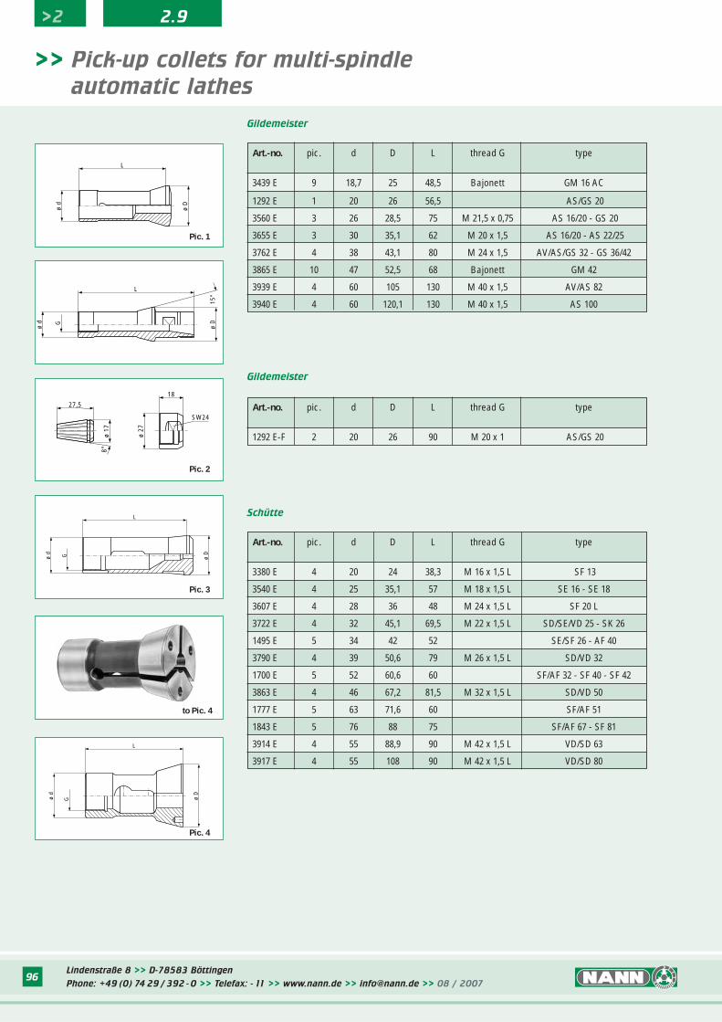
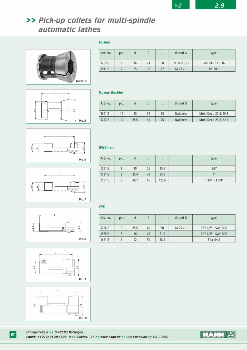
>> Pick-up collets for multi-spindle
automatic lathes
ø d
ø D
G
L
Pic. 4
Schütte
L
ø D
ø d
Pic. 1
Art.-no. pic. d D L thread G type
1292 E-F 2 20 26 90 M 20 x 1 AS/GS 20
Gildemeister
ø d G
L
ø D
15°
27,5
ø 17
8°
18
SW24
ø 27
Pic. 2
ø d G ø D
L
Pic. 3
Gildemeister
>2 2.9
Art.-no. pic. d D L thread G type
3439 E 9 18,7 25 48,5 Bajonett GM 16 AC
1292 E 1 20 26 56,5 AS/GS 20
3560 E 3 26 28,5 75 M 21,5 x 0,75 AS 16/20 - GS 20
3655 E 3 30 35,1 62 M 20 x 1,5 AS 16/20 - AS 22/25
3762 E 4 38 43,1 80 M 24 x 1,5 AV/AS/GS 32 - GS 36/42
3865 E 10 47 52,5 68 Bajonett GM 42
3939 E 4 60 105 130 M 40 x 1,5 AV/AS 82
3940 E 4 60 120,1 130 M 40 x 1,5 AS 100
Art.-no. pic. d D L thread G type
3380 E 4 20 24 38,3 M 16 x 1,5 L SF 13
3540 E 4 25 35,1 57 M 18 x 1,5 L SE 16 - SE 18
3607 E 4 28 36 48 M 24 x 1,5 L SF 20 L
3722 E 4 32 45,1 69,5 M 22 x 1,5 L SD/SE/VD 25 - SK 26
1495 E 5 34 42 52 SE/SF 26 - AF 40
3790 E 4 39 50,6 79 M 26 x 1,5 L SD/VD 32
1700 E 5 52 60,6 60 SF/AF 32 - SF 40 - SF 42
3863 E 4 46 67,2 81,5 M 32 x 1,5 L SD/VD 50
1777 E 5 63 71,6 60 SF/AF 51
1843 E 5 76 88 75 SF/AF 67 - SF 81
3914 E 4 55 88,9 90 M 42 x 1,5 L VD/SD 63
3917 E 4 55 108 90 M 42 x 1,5 L VD/SD 80
to Pic. 4
Lindenstraße 8 >> D-78583 Böttingen
Phone: +49 (0) 74 29 / 392 - 0 >> Telefax: - 11 >> www.nann.de >> [email protected] >> 08 / 200797
>> Pick-up collets for multi-spindle
automatic lathes
Art.-no. pic. d D L type
1261 E 8 19 26 55,6 5/8“
1381 E 8 25,4 38 93,6 1“
1561 E 8 39,7 65 120,6 1.3/8“ - 1.3/4“
Wickman
Art.-no. pic. d D L thread G type
3756 E 3 35,5 40 80 M 25 x 1 SAY 6/25 - SAY 6/32
1525 E 5 36 45 61,5 SAY 6/25 - SAY 6/32
1621 E 1 42 54 78,5 SAY 6/42
ZPS
ø d G ø D
L
Pic. 6
ø d G ø D
L
Pic. 7
ø d
ø D
L
Pic. 8
ø d
L
ø D
Pic. 5
ø d
L
ø D
Pic. 9
Art.-no. pic. d D L thread G type
3263 E 6 16 21 58 M 14 x 0,75 AS 14 - SAS 16
3541 E 7 25 35 77 M 22 x 1 BS 20 B
Tornos
L
ø d
ø D
Pic. 10
Tornos Bechler
>2 2.9
Art.-no. pic. d D L thread G type
3601 E 10 28 32 68 Bajonett Multi Deco 20-6, 20-8
3757 E 10 35,5 40 75 Bajonett Multi Deco 26-6, 32-6
to Pic. 5
98
>2 2.9
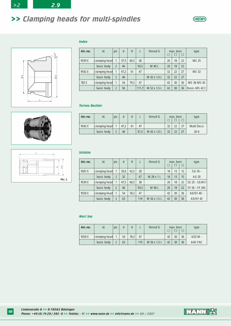
Index
>> Clamping heads for multi-spindles
Art.-no. id. pic. d D L thread G max. bore type� ∫∫ ºº
9539 E clamping head 1 37,5 60,5 38 26 18 22 MS 25
basic body 2 46 93,5 M 40 L 26 18 22
9542 E clamping head 1 47,2 61 47 32 22 27 MS 32
basic body 2 46 M 42 x 1,0 L 32 22 27
782 E clamping head 1 54 79,5 47 42 30 36 MS 36-MS 42
basic body 2 56 111,7 M 52 x 1,5 L 42 30 36 Basic-MS 42 C
Tornos Bechler
Art.-no. id. pic. d D L thread G max. bore type� ∫∫ ºº
9542 E clamping head 1 47,2 61 47 32 22 27 Multi Deco
basic body 2 46 81,5 M 42 x 1,0 L 32 22 27 26-6
Schütte
Art.-no. id. pic. d D L thread G max. bore type� ∫∫ ºº
9507 E clamping head 1 29,6 42,5 28 18 13 15 SG 18 -
basic body 2 32 67 M 28 x 1 L 18 13 15 AG 20
9539 E clamping head 1 47,5 60,5 38 26 18 22 SE 25 - SE/AF/
basic body 2 46 93,5 M 40 L 26 18 22 SF 26 - SF 26S
9550 E clamping head 1 54 78,3 47 42 30 36 AD/SF 40 -
basic body 2 63 119 M 56 x 1,5 L 42 30 36 AD/SF 42
Mori Say
Art.-no. id. pic. d D L thread G max. bore type� ∫∫ ºº
9550 E clamping head 1 54 78,3 47 42 30 36 6/32 M -
basic body 2 63 119 M 56 x 1,5 L 42 30 36 6/42 CNC
a°
L
Ø d
Ø D
ø
d
L
G
Pic. 1
Lindenstraße 8 >> D-78583 Böttingen
Phone: +49 (0) 74 29 / 392 - 0 >> Telefax: - 11 >> www.nann.de >> [email protected] >> 08 / 200798
99
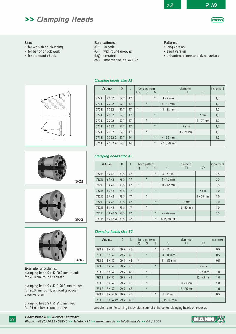
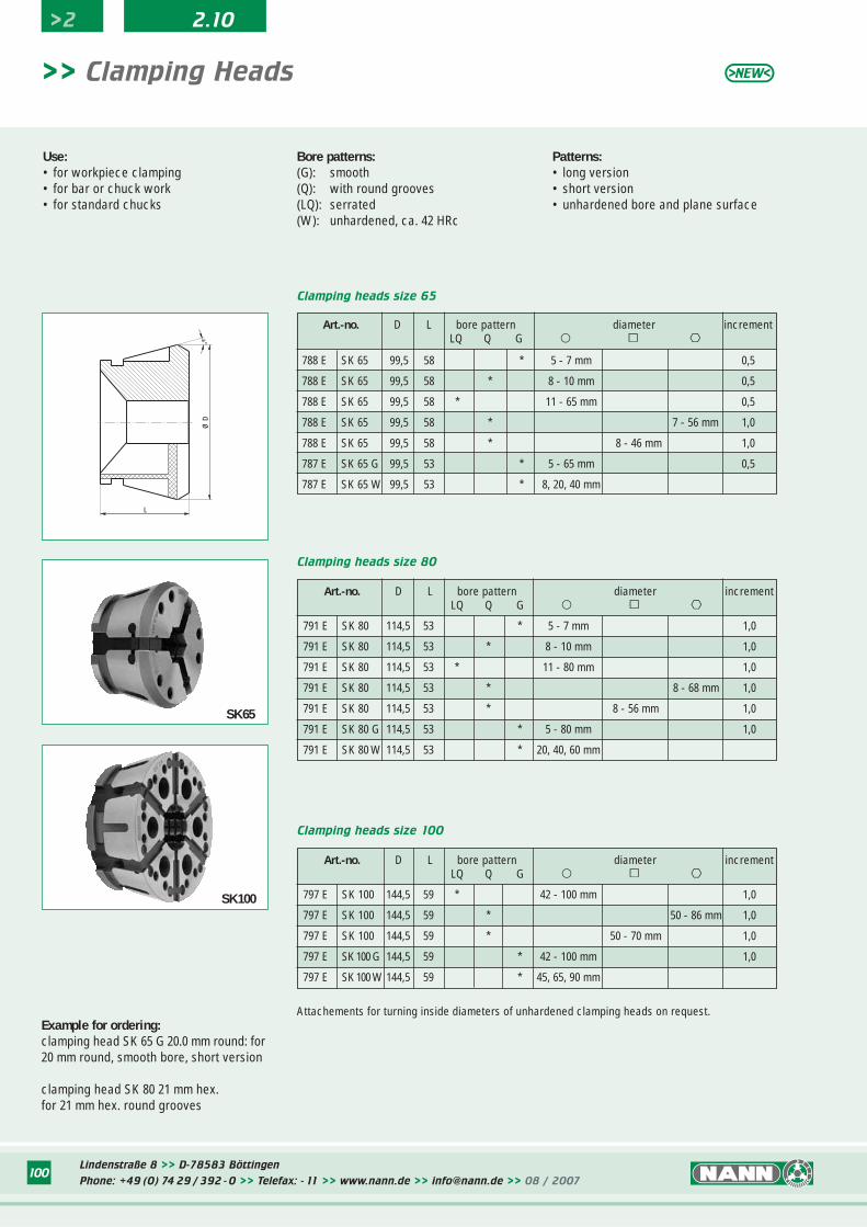
>> Clamping Heads
Bore patterns: (G): smooth(Q): with round grooves(LQ): serrated(W): unhardened, ca. 42 HRc
Patterns:• long version• short version• unhardened bore and plane surface
a°
L
Ø D
>2 2.10
Art.-no. D L bore pattern diameter incrementLQ Q G � ∫∫ ºº
772 E SK 32 57,7 47 * 4 - 7 mm 1,0
772 E SK 32 57,7 47 * 8 - 10 mm 1,0
772 E SK 32 57,7 47 * 11 - 32 mm 1,0
772 E SK 32 57,7 47 * 7 mm 1,0
772 E SK 32 57,7 47 * 8 - 27 mm 1,0
772 E SK 32 57,7 47 * 7 mm 1,0
772 E SK 32 57,7 47 * 8 - 22 mm 1,0
771 E SK 32 G 57,7 44 * 4 - 32 mm 1,0
771 E SK 32 W 57,7 44 * 5, 15, 20 mm
Art.-no. D L bore pattern diameter incrementLQ Q G � ∫∫ ºº
782 E SK 42 79,5 47 * 4 - 7 mm 0,5
782 E SK 42 79,5 47 * 8 - 10 mm 0,5
782 E SK 42 79,5 47 * 11 - 42 mm 0,5
782 E SK 42 79,5 47 * 7 mm 1,0
782 E SK 42 79,5 47 * 8 - 36 mm 1,0
782 E SK 42 79,5 47 * 7 mm 1,0
782 E SK 42 79,5 47 * 8 - 30 mm 1,0
781 E SK 42 G 79,5 42 * 4 - 42 mm 0,5
781 E SK 42 W 79,5 42 * 8, 15, 30 mm
Art.-no. D L bore pattern diameter incrementLQ Q G � ∫∫ ºº
783 E SK 52 79,5 46 * 4 - 7 mm 0,5
783 E SK 52 79,5 46 * 8 - 10 mm 0,5
783 E SK 52 79,5 46 * 11 - 52 mm 0,5
783 E SK 52 79,5 46 * 7 mm
783 E SK 52 79,5 46 * 8 - 9 mm 1,0
783 E SK 52 79,5 46 * 10 - 45 mm 1,0
783 E SK 52 79,5 46 * 8 - 9 mm 1,0
783 E SK 52 79,5 46 * 8 - 36 mm 1,0
783 E SK 52 G 79,5 46 * 4 - 52 mm 0,5
783 E SK 52 W 79,5 46 8, 15, 30 mm
Clamping heads size 42
Clamping heads size 52
Clamping heads size 32
SK42
SK32
Attachements for turning inside diameters of unhardened clamping heads on request.
SK65
Use:• for workpiece clamping• for bar or chuck work• for standard chucks
Example for ordering:clamping head SK 42 20.0 mm round:for 20.0 mm round serrated
clamping head SK 42 G 20.0 mm round:for 20.0 mm round, without grooves,short version
clamping head SK 65 21.0 mm hex.for 21 mm hex. round grooves
Lindenstraße 8 >> D-78583 Böttingen
Phone: +49 (0) 74 29 / 392 - 0 >> Telefax: - 11 >> www.nann.de >> [email protected] >> 08 / 200799
100
>2 2.10
>> Clamping Heads
Bore patterns: (G): smooth(Q): with round grooves(LQ): serrated(W): unhardened, ca. 42 HRc
Patterns:• long version• short version• unhardened bore and plane surface
Art.-no. D L bore pattern diameter incrementLQ Q G � ∫∫ ºº
788 E SK 65 99,5 58 * 5 - 7 mm 0,5
788 E SK 65 99,5 58 * 8 - 10 mm 0,5
788 E SK 65 99,5 58 * 11 - 65 mm 0,5
788 E SK 65 99,5 58 * 7 - 56 mm 1,0
788 E SK 65 99,5 58 * 8 - 46 mm 1,0
787 E SK 65 G 99,5 53 * 5 - 65 mm 0,5
787 E SK 65 W 99,5 53 * 8, 20, 40 mm
Clamping heads size 65
Art.-no. D L bore pattern diameter incrementLQ Q G � ∫∫ ºº
791 E SK 80 114,5 53 * 5 - 7 mm 1,0
791 E SK 80 114,5 53 * 8 - 10 mm 1,0
791 E SK 80 114,5 53 * 11 - 80 mm 1,0
791 E SK 80 114,5 53 * 8 - 68 mm 1,0
791 E SK 80 114,5 53 * 8 - 56 mm 1,0
791 E SK 80 G 114,5 53 * 5 - 80 mm 1,0
791 E SK 80 W 114,5 53 * 20, 40, 60 mm
Clamping heads size 80
Art.-no. D L bore pattern diameter incrementLQ Q G � ∫∫ ºº
797 E SK 100 144,5 59 * 42 - 100 mm 1,0
797 E SK 100 144,5 59 * 50 - 86 mm 1,0
797 E SK 100 144,5 59 * 50 - 70 mm 1,0
797 E SK 100 G 144,5 59 * 42 - 100 mm 1,0
797 E SK 100 W 144,5 59 * 45, 65, 90 mm
Clamping heads size 100
a°
L
Ø D
Example for ordering:clamping head SK 65 G 20.0 mm round: for20 mm round, smooth bore, short version
clamping head SK 80 21 mm hex.for 21 mm hex. round grooves
SK65
SK100
Attachements for turning inside diameters of unhardened clamping heads on request.
Use:• for workpiece clamping• for bar or chuck work• for standard chucks
Lindenstraße 8 >> D-78583 Böttingen
Phone: +49 (0) 74 29 / 392 - 0 >> Telefax: - 11 >> www.nann.de >> [email protected] >> 08 / 2007100
101
>2 2.10
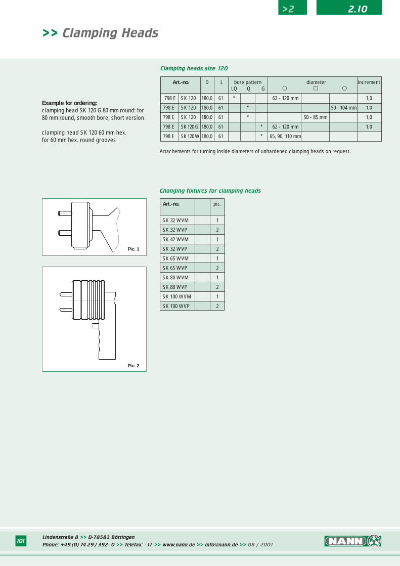
Changing fixtures for clamping heads
Art.-no. pic.
SK 32 WVM 1
SK 32 WVP 2
SK 42 WVM 1
SK 32 WVP 2
SK 65 WVM 1
SK 65 WVP 2
SK 80 WVM 1
SK 80 WVP 2
SK 100 WVM 1
SK 100 WVP 2
Pic. 1
Pic. 2
>> Clamping Heads
Art.-no. D L bore pattern diameter incrementLQ Q G � ∫∫ ºº
798 E SK 120 180,0 61 * 62 - 120 mm 1,0
798 E SK 120 180,0 61 * 50 - 104 mm 1,0
798 E SK 120 180,0 61 * 50 - 85 mm 1,0
798 E SK 120 G 180,0 61 * 62 - 120 mm 1,0
798 E SK 120 W 180,0 61 * 65, 90, 110 mm
Clamping heads size 120
Example for ordering:clamping head SK 120 G 80 mm round: for80 mm round, smooth bore, short version
clamping head SK 120 60 mm hex. for 60 mm hex. round grooves
Attachements for turning inside diameters of unhardened clamping heads on request.
Lindenstraße 8 >> D-78583 Böttingen
Phone: +49 (0) 74 29 / 392 - 0 >> Telefax: - 11 >> www.nann.de >> [email protected] >> 08 / 2007101
Lindenstraße 8 >> D-78583 Böttingen
Phone: +49 (0) 74 29 / 392 - 0 >> Telefax: - 11 >> www.nann.de >> [email protected] >> 08 / 2007102
>2 2.10
>> Drawback collets
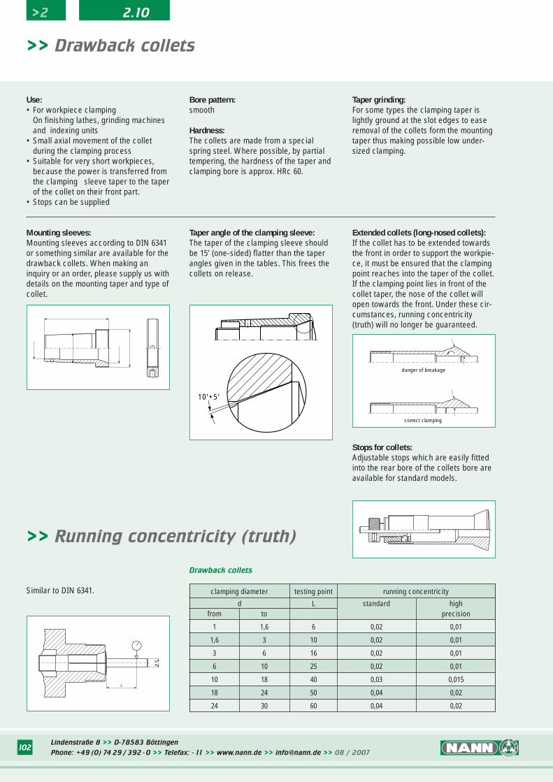
Use:• For workpiece clamping
On finishing lathes, grinding machinesand indexing units
• Small axial movement of the collet during the clamping process
• Suitable for very short workpieces, because the power is transferred from the clamping sleeve taper to the taper of the collet on their front part.
• Stops can be supplied
correct clamping
danger of breakage
10'+5'
Bore pattern: smooth
Hardness:The collets are made from a specialspring steel. Where possible, by partialtempering, the hardness of the taper andclamping bore is approx. HRc 60.
Taper grinding:For some types the clamping taper islightly ground at the slot edges to easeremoval of the collets form the mountingtaper thus making possible low under-sized clamping.
Taper angle of the clamping sleeve:The taper of the clamping sleeve shouldbe 15’ (one-sided) flatter than the taperangles given in the tables. This frees thecollets on release.
Stops for collets:Adjustable stops which are easily fittedinto the rear bore of the collets bore areavailable for standard models.
Extended collets (long-nosed collets):If the collet has to be extended towardsthe front in order to support the workpie-ce, it must be ensured that the clampingpoint reaches into the taper of the collet.If the clamping point lies in front of thecollet taper, the nose of the collet willopen towards the front. Under these cir-cumstances, running concentricity(truth) will no longer be guaranteed.
Mounting sleeves:Mounting sleeves according to DIN 6341or something similar are available for thedrawback collets. When making aninquiry or an order, please supply us withdetails on the mounting taper and type ofcollet.
clamping diameter testing point running concentricity
d L standard highfrom to precision
1 1,6 6 0,02 0,01
1,6 3 10 0,02 0,01
3 6 16 0,02 0,01
6 10 25 0,02 0,01
10 18 40 0,03 0,015
18 24 50 0,04 0,02
24 30 60 0,04 0,02
Drawback collets
L
ø d
Similar to DIN 6341.
>> Running concentricity (truth)
Lindenstraße 8 >> D-78583 Böttingen
Phone: +49 (0) 74 29 / 392 - 0 >> Telefax: - 11 >> www.nann.de >> [email protected] >> 08 / 2007103
>> Drawback collets
K°
ø d
L
ø D
K°
Gø d
L
ø D
Pic. 1
Pic. 2
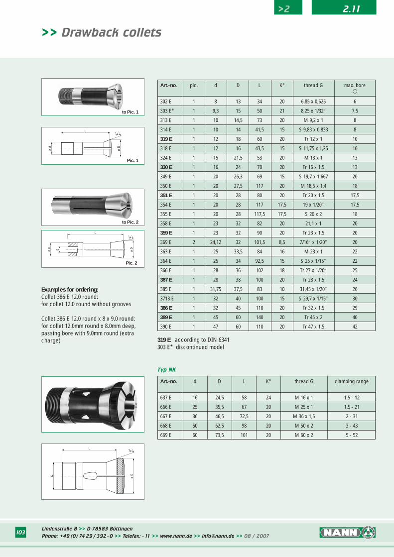
Examples for ordering:Collet 386 E 12.0 round:for collet 12.0 round without grooves
Collet 386 E 12.0 round x 8 x 9.0 round:for collet 12.0mm round x 8.0mm deep,passing bore with 9.0mm round (extracharge) 319 E according to DIN 6341
303 E* discontinued model
Typ NK
Art.-no. d D L K° thread G clamping range
637 E 16 24,5 58 24 M 16 x 1 1,5 - 12
666 E 25 35,5 67 20 M 25 x 1 1,5 - 21
667 E 36 46,5 72,5 20 M 36 x 1,5 2 - 31
668 E 50 62,5 98 20 M 50 x 2 3 - 43
669 E 60 73,5 101 20 M 60 x 2 5 - 52
L
G ø D
K°
Art.-no. pic. d D L K° thread G max. bore�
302 E 1 8 13 34 20 6,85 x 0,625 6
303 E* 1 9,3 15 50 21 8,25 x 1/32“ 7,5
313 E 1 10 14,5 73 20 M 9,2 x 1 8
314 E 1 10 14 41,5 15 S 9,83 x 0,833 8
319 E 1 12 18 60 20 Tr 12 x 1 10
318 E 1 12 16 43,5 15 S 11,75 x 1,25 10
324 E 1 15 21,5 53 20 M 13 x 1 13
330 E 1 16 24 70 20 Tr 16 x 1,5 13
349 E 1 20 26,3 69 15 S 19,7 x 1,667 20
350 E 1 20 27,5 117 20 M 18,5 x 1,4 18
351 E 1 20 28 80 20 Tr 20 x 1,5 17,5
354 E 1 20 28 117 17,5 19 x 1/20“ 17,5
355 E 1 20 28 117,5 17,5 S 20 x 2 18
358 E 1 23 32 82 20 21,1 x 1 20
359 E 1 23 32 90 20 Tr 23 x 1,5 20
369 E 2 24,12 32 101,5 8,5 7/16“ x 1/20“ 20
363 E 1 25 33,5 84 16 M 23 x 1 22
364 E 1 25 34 92,5 15 S 25 x 1/15“ 22
366 E 1 28 36 102 18 Tr 27 x 1/20“ 25
367 E 1 28 38 100 20 Tr 28 x 1,5 24
385 E 1 31,75 37,5 83 10 31,45 x 1/20“ 26
3713 E 1 32 40 100 15 S 29,7 x 1/15“ 30
386 E 1 32 45 110 20 Tr 32 x 1,5 29
389 E 1 45 60 140 20 Tr 45 x 2 40
390 E 1 47 60 110 20 Tr 47 x 1,5 42
>2 2.11
to Pic. 1
to Pic. 2
Lindenstraße 8 >> D-78583 Böttingen
Phone: +49 (0) 74 29 / 392 - 0 >> Telefax: - 11 >> www.nann.de >> [email protected] >> 08 / 2007104
>2 2.11
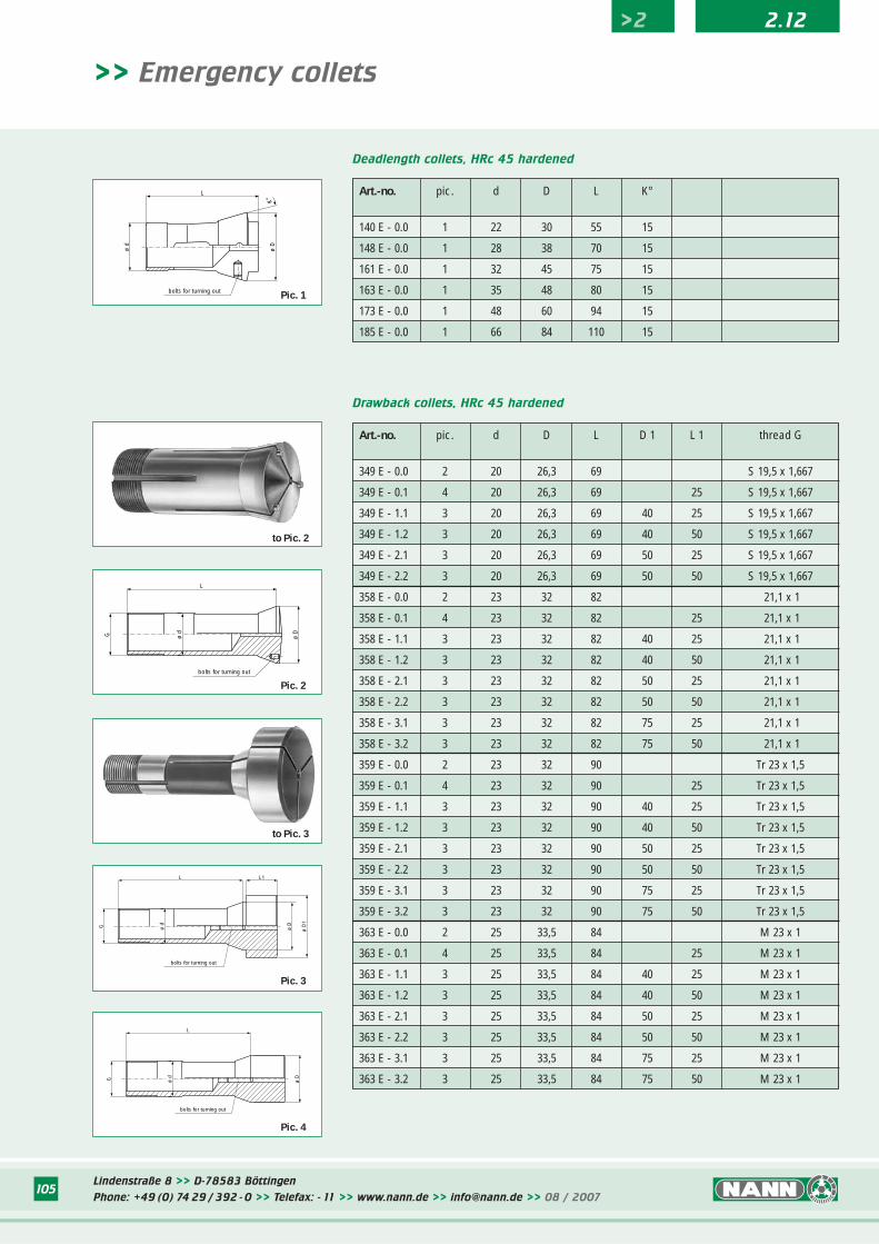
>> Emergency collets
Use:Emergency collets are used for holdingsmaller series workpieces when no stan-dard collet is available. Unlike the stan-dard collet, with its hardened taper andclamping bore, emergency collets onlyhave a hardness of approx. HRc 45. Thecustomer can therefore enlarge the boreof the collet.
To enlarge the bore, the emergency col-let is clamped on a bolt in the rear of theclamping bore or on pins in the slots andturned out in this position.
Patterns: • Deadlength collets• Drawback collets
Short pattern:Like standard colletsLarger and longer pattern:These collets can be used to clamp larger, shorter workpieces.
• Drawback collets with extended tapers:These collets are used when the machine has been fitted with an extended clamping taper (e. g.Weiler turning machines).
• Drawback collets for internal clamping:For holding workpieces by the bore: These require the corresponding taper insert (e.g. Weiler turning machines).
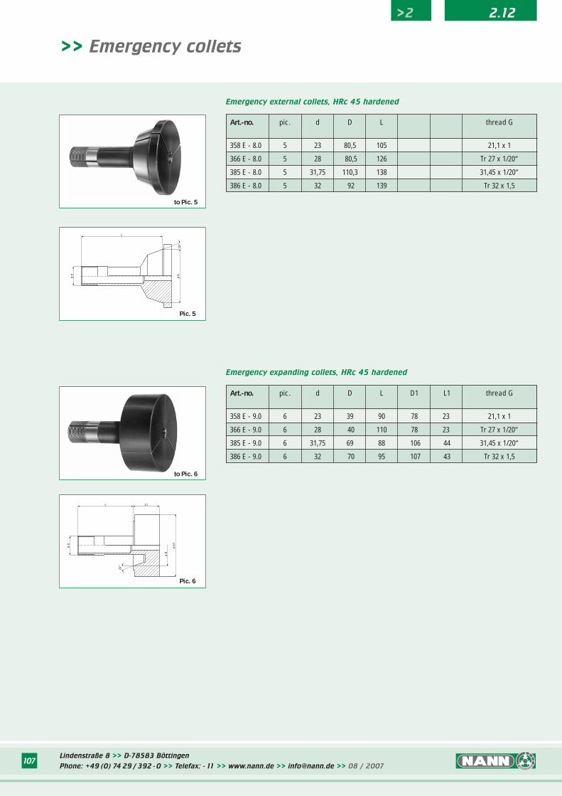
• External step collets:For clamping very short parts:The external step collets have severalsteps so that the whole range can beclamped using only a few collets. These are only suitable for very short workpieces.
• Internal step collets:For clamping rings from inside:The expanding collets have several steps so that the whole range can be clamped using only a few collets. They are only suitable for very short workpieces.
Note: The centrifugal force resulting at highspeeds can lead to a lessening of theclamping power and, in extreme case,breaking of the collets.
Please follow accident-preventioninstructions.
Lindenstraße 8 >> D-78583 Böttingen
Phone: +49 (0) 74 29 / 392 - 0 >> Telefax: - 11 >> www.nann.de >> [email protected] >> 08 / 2007105
K°
ø d
bolts for turning out
ø D
L
Art.-no. pic. d D L D 1 L 1 thread G
349 E - 0.0 2 20 26,3 69 S 19,5 x 1,667
349 E - 0.1 4 20 26,3 69 25 S 19,5 x 1,667
349 E - 1.1 3 20 26,3 69 40 25 S 19,5 x 1,667
349 E - 1.2 3 20 26,3 69 40 50 S 19,5 x 1,667
349 E - 2.1 3 20 26,3 69 50 25 S 19,5 x 1,667
349 E - 2.2 3 20 26,3 69 50 50 S 19,5 x 1,667
358 E - 0.0 2 23 32 82 21,1 x 1
358 E - 0.1 4 23 32 82 25 21,1 x 1
358 E - 1.1 3 23 32 82 40 25 21,1 x 1
358 E - 1.2 3 23 32 82 40 50 21,1 x 1
358 E - 2.1 3 23 32 82 50 25 21,1 x 1
358 E - 2.2 3 23 32 82 50 50 21,1 x 1
358 E - 3.1 3 23 32 82 75 25 21,1 x 1
358 E - 3.2 3 23 32 82 75 50 21,1 x 1
359 E - 0.0 2 23 32 90 Tr 23 x 1,5
359 E - 0.1 4 23 32 90 25 Tr 23 x 1,5
359 E - 1.1 3 23 32 90 40 25 Tr 23 x 1,5
359 E - 1.2 3 23 32 90 40 50 Tr 23 x 1,5
359 E - 2.1 3 23 32 90 50 25 Tr 23 x 1,5
359 E - 2.2 3 23 32 90 50 50 Tr 23 x 1,5
359 E - 3.1 3 23 32 90 75 25 Tr 23 x 1,5
359 E - 3.2 3 23 32 90 75 50 Tr 23 x 1,5
363 E - 0.0 2 25 33,5 84 M 23 x 1
363 E - 0.1 4 25 33,5 84 25 M 23 x 1
363 E - 1.1 3 25 33,5 84 40 25 M 23 x 1
363 E - 1.2 3 25 33,5 84 40 50 M 23 x 1
363 E - 2.1 3 25 33,5 84 50 25 M 23 x 1
363 E - 2.2 3 25 33,5 84 50 50 M 23 x 1
363 E - 3.1 3 25 33,5 84 75 25 M 23 x 1
363 E - 3.2 3 25 33,5 84 75 50 M 23 x 1
Drawback collets, HRc 45 hardened
G
L
ø d
bolts for turning out
ø D
Pic. 2
G ø d
ø D
L L1
ø D
1
bolts for turning out
>> Emergency collets
Pic. 3
Art.-no. pic. d D L K°
140 E - 0.0 1 22 30 55 15
148 E - 0.0 1 28 38 70 15
161 E - 0.0 1 32 45 75 15
163 E - 0.0 1 35 48 80 15
173 E - 0.0 1 48 60 94 15
185 E - 0.0 1 66 84 110 15
Deadlength collets, HRc 45 hardened
Pic. 1
G ø d
ø D
L
bolts for turning out
Pic. 4
>2 2.12
to Pic. 2
to Pic. 3
Lindenstraße 8 >> D-78583 Böttingen
Phone: +49 (0) 74 29 / 392 - 0 >> Telefax: - 11 >> www.nann.de >> [email protected] >> 08 / 2007106
>2 2.12
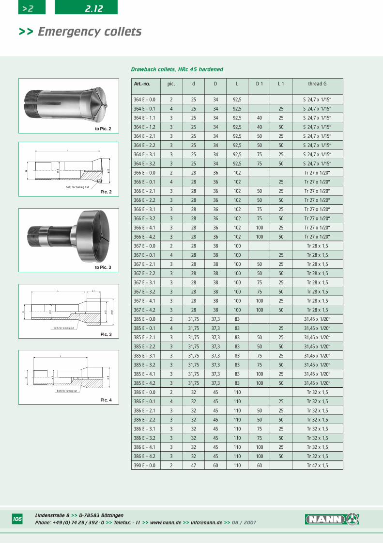
Art.-no. pic. d D L D 1 L 1 thread G
364 E - 0.0 2 25 34 92,5 S 24,7 x 1/15“
364 E - 0.1 4 25 34 92,5 25 S 24,7 x 1/15“
364 E - 1.1 3 25 34 92,5 40 25 S 24,7 x 1/15“
364 E - 1.2 3 25 34 92,5 40 50 S 24,7 x 1/15“
364 E - 2.1 3 25 34 92,5 50 25 S 24,7 x 1/15“
364 E - 2.2 3 25 34 92,5 50 50 S 24,7 x 1/15“
364 E - 3.1 3 25 34 92,5 75 25 S 24,7 x 1/15“
364 E - 3.2 3 25 34 92,5 75 50 S 24,7 x 1/15“
366 E - 0.0 2 28 36 102 Tr 27 x 1/20“
366 E - 0.1 4 28 36 102 25 Tr 27 x 1/20“
366 E - 2.1 3 28 36 102 50 25 Tr 27 x 1/20“
366 E - 2.2 3 28 36 102 50 50 Tr 27 x 1/20“
366 E - 3.1 3 28 36 102 75 25 Tr 27 x 1/20“
366 E - 3.2 3 28 36 102 75 50 Tr 27 x 1/20“
366 E - 4.1 3 28 36 102 100 25 Tr 27 x 1/20“
366 E - 4.2 3 28 36 102 100 50 Tr 27 x 1/20“
367 E - 0.0 2 28 38 100 Tr 28 x 1,5
367 E - 0.1 4 28 38 100 25 Tr 28 x 1,5
367 E - 2.1 3 28 38 100 50 25 Tr 28 x 1,5
367 E - 2.2 3 28 38 100 50 50 Tr 28 x 1,5
367 E - 3.1 3 28 38 100 75 25 Tr 28 x 1,5
367 E - 3.2 3 28 38 100 75 50 Tr 28 x 1,5
367 E - 4.1 3 28 38 100 100 25 Tr 28 x 1,5
367 E - 4.2 3 28 38 100 100 50 Tr 28 x 1,5
385 E - 0.0 2 31,75 37,3 83 31,45 x 1/20“
385 E - 0.1 4 31,75 37,3 83 25 31,45 x 1/20“
385 E - 2.1 3 31,75 37,3 83 50 25 31,45 x 1/20“
385 E - 2.2 3 31,75 37,3 83 50 50 31,45 x 1/20“
385 E - 3.1 3 31,75 37,3 83 75 25 31,45 x 1/20“
385 E - 3.2 3 31,75 37,3 83 75 50 31,45 x 1/20“
385 E - 4.1 3 31,75 37,3 83 100 25 31,45 x 1/20“
385 E - 4.2 3 31,75 37,3 83 100 50 31,45 x 1/20“
386 E - 0.0 2 32 45 110 Tr 32 x 1,5
386 E - 0.1 4 32 45 110 25 Tr 32 x 1,5
386 E - 2.1 3 32 45 110 50 25 Tr 32 x 1,5
386 E - 2.2 3 32 45 110 50 50 Tr 32 x 1,5
386 E - 3.1 3 32 45 110 75 25 Tr 32 x 1,5
386 E - 3.2 3 32 45 110 75 50 Tr 32 x 1,5
386 E - 4.1 3 32 45 110 100 25 Tr 32 x 1,5
386 E - 4.2 3 32 45 110 100 50 Tr 32 x 1,5
390 E - 0.0 2 47 60 110 60 Tr 47 x 1,5
Drawback collets, HRc 45 hardened
G ø d
ø D
L L1
ø D
1
bolts for turning out
>> Emergency collets
Pic. 3
G
L
ø d
bolts for turning out
ø D
Pic. 2
G ø d
ø D
L
bolts for turning out
Pic. 4
to Pic. 2
to Pic. 3
Lindenstraße 8 >> D-78583 Böttingen
Phone: +49 (0) 74 29 / 392 - 0 >> Telefax: - 11 >> www.nann.de >> [email protected] >> 08 / 2007107
Art.-no. pic. d D L thread G
358 E - 8.0 5 23 80,5 105 21,1 x 1
366 E - 8.0 5 28 80,5 126 Tr 27 x 1/20“
385 E - 8.0 5 31,75 110,3 138 31,45 x 1/20“
386 E - 8.0 5 32 92 139 Tr 32 x 1,5
Art.-no. pic. d D L D1 L1 thread G
358 E - 9.0 6 23 39 90 78 23 21,1 x 1
366 E - 9.0 6 28 40 110 78 23 Tr 27 x 1/20“
385 E - 9.0 6 31,75 69 88 106 44 31,45 x 1/20“
386 E - 9.0 6 32 70 95 107 43 Tr 32 x 1,5
Emergency external collets, HRc 45 hardened
Emergency expanding collets, HRc 45 hardened
ø D
ø d
L
20°
L
ø d
ø D
20°
L1
ø D
1
Pic. 5
Pic. 6
>> Emergency collets
>2 2.12
to Pic. 5
to Pic. 6
Lindenstraße 8 >> D-78583 Böttingen
Phone: +49 (0) 74 29 / 392 - 0 >> Telefax: - 11 >> www.nann.de >> [email protected] >> 08 / 2007108
>2 2.12
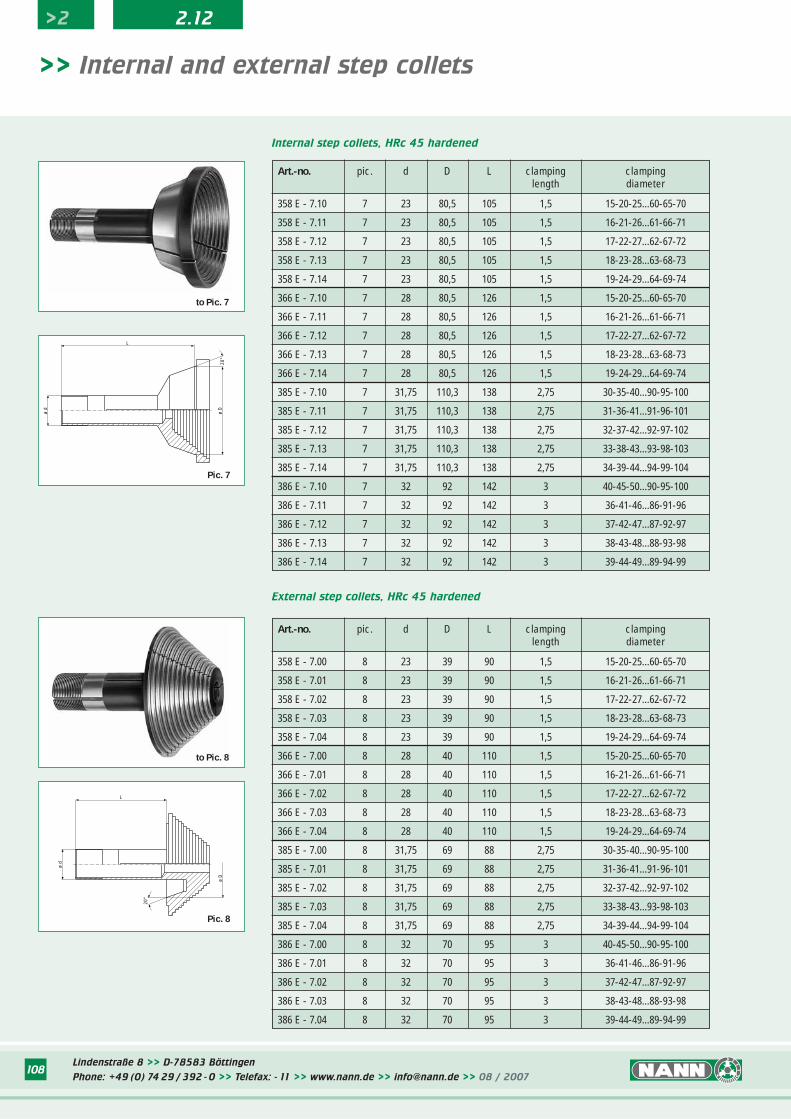
Art.-no. pic. d D L clamping clampinglength diameter
358 E - 7.00 8 23 39 90 1,5 15-20-25...60-65-70
358 E - 7.01 8 23 39 90 1,5 16-21-26...61-66-71
358 E - 7.02 8 23 39 90 1,5 17-22-27...62-67-72
358 E - 7.03 8 23 39 90 1,5 18-23-28...63-68-73
358 E - 7.04 8 23 39 90 1,5 19-24-29...64-69-74
366 E - 7.00 8 28 40 110 1,5 15-20-25...60-65-70
366 E - 7.01 8 28 40 110 1,5 16-21-26...61-66-71
366 E - 7.02 8 28 40 110 1,5 17-22-27...62-67-72
366 E - 7.03 8 28 40 110 1,5 18-23-28...63-68-73
366 E - 7.04 8 28 40 110 1,5 19-24-29...64-69-74
385 E - 7.00 8 31,75 69 88 2,75 30-35-40...90-95-100
385 E - 7.01 8 31,75 69 88 2,75 31-36-41...91-96-101
385 E - 7.02 8 31,75 69 88 2,75 32-37-42...92-97-102
385 E - 7.03 8 31,75 69 88 2,75 33-38-43...93-98-103
385 E - 7.04 8 31,75 69 88 2,75 34-39-44...94-99-104
386 E - 7.00 8 32 70 95 3 40-45-50...90-95-100
386 E - 7.01 8 32 70 95 3 36-41-46...86-91-96
386 E - 7.02 8 32 70 95 3 37-42-47...87-92-97
386 E - 7.03 8 32 70 95 3 38-43-48...88-93-98
386 E - 7.04 8 32 70 95 3 39-44-49...89-94-99
Art.-no. pic. d D L clamping clampinglength diameter
358 E - 7.10 7 23 80,5 105 1,5 15-20-25...60-65-70
358 E - 7.11 7 23 80,5 105 1,5 16-21-26...61-66-71
358 E - 7.12 7 23 80,5 105 1,5 17-22-27...62-67-72
358 E - 7.13 7 23 80,5 105 1,5 18-23-28...63-68-73
358 E - 7.14 7 23 80,5 105 1,5 19-24-29...64-69-74
366 E - 7.10 7 28 80,5 126 1,5 15-20-25...60-65-70
366 E - 7.11 7 28 80,5 126 1,5 16-21-26...61-66-71
366 E - 7.12 7 28 80,5 126 1,5 17-22-27...62-67-72
366 E - 7.13 7 28 80,5 126 1,5 18-23-28...63-68-73
366 E - 7.14 7 28 80,5 126 1,5 19-24-29...64-69-74
385 E - 7.10 7 31,75 110,3 138 2,75 30-35-40...90-95-100
385 E - 7.11 7 31,75 110,3 138 2,75 31-36-41...91-96-101
385 E - 7.12 7 31,75 110,3 138 2,75 32-37-42...92-97-102
385 E - 7.13 7 31,75 110,3 138 2,75 33-38-43...93-98-103
385 E - 7.14 7 31,75 110,3 138 2,75 34-39-44...94-99-104
386 E - 7.10 7 32 92 142 3 40-45-50...90-95-100
386 E - 7.11 7 32 92 142 3 36-41-46...86-91-96
386 E - 7.12 7 32 92 142 3 37-42-47...87-92-97
386 E - 7.13 7 32 92 142 3 38-43-48...88-93-98
386 E - 7.14 7 32 92 142 3 39-44-49...89-94-99
Internal step collets, HRc 45 hardened
L
ø d
ø D
20°
Pic. 8
ø d
L
ø D
20°
External step collets, HRc 45 hardened
>> Internal and external step collets
Pic. 7
to Pic. 7
to Pic. 8
Lindenstraße 8 >> D-78583 Böttingen
Phone: +49 (0) 74 29 / 392 - 0 >> Telefax: - 11 >> www.nann.de >> [email protected] >> 08 / 2007109
>2 2.13
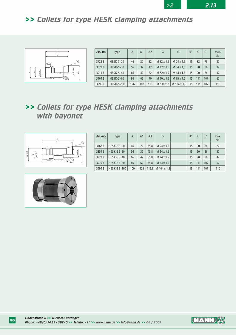
>> Collets for type HESK clamping attachments
Art.-no. type A A1 A2 G G1 K° C C1 max.dia.
3723 E HESK-S-20 46 22 32 M 32 x 1,5 M 24 x 1,5 15 82 78 22
3829 E HESK-S-30 56 32 42 M 42 x 1,5 M 34 x 1,5 15 90 86 32
3911 E HESK-S-40 66 42 52 M 52 x 1,5 M 44 x 1,5 15 90 86 42
3964 E HESK-S-60 86 62 70 M 70 x 1,5 M 65 x 1,5 15 111 107 62
3996 E HESK-S-100 126 102 110 M 110 x 2 M 104 x 1,5 15 111 107 110
C
C1
ø A2g7
G1
G
ø A
1H7
ø A
ø d
max
.
K°
>> Collets for type HESK clamping attachments
with bayonet
øA3h
6
øA1H
7
øAødm
ax.
C1C
G
K°
Art.-no. type A A1 A3 G K° C C1 max.dia.
3768 E HESK-SB-20 46 22 35,8 M 24 x 1,5 15 90 86 22
3859 E HESK-SB-30 56 32 45,8 M 34 x 1,5 15 90 86 32
3922 E HESK-SB-40 66 42 55,8 M 44 x 1,5 15 90 86 42
3970 E HESK-SB-60 86 62 75,8 M 64 x 1,5 15 111 107 62
3999 E HESK-SB-100 100 126 115,8 M 104 x 1,5 15 111 107 110
110
>2 2.14
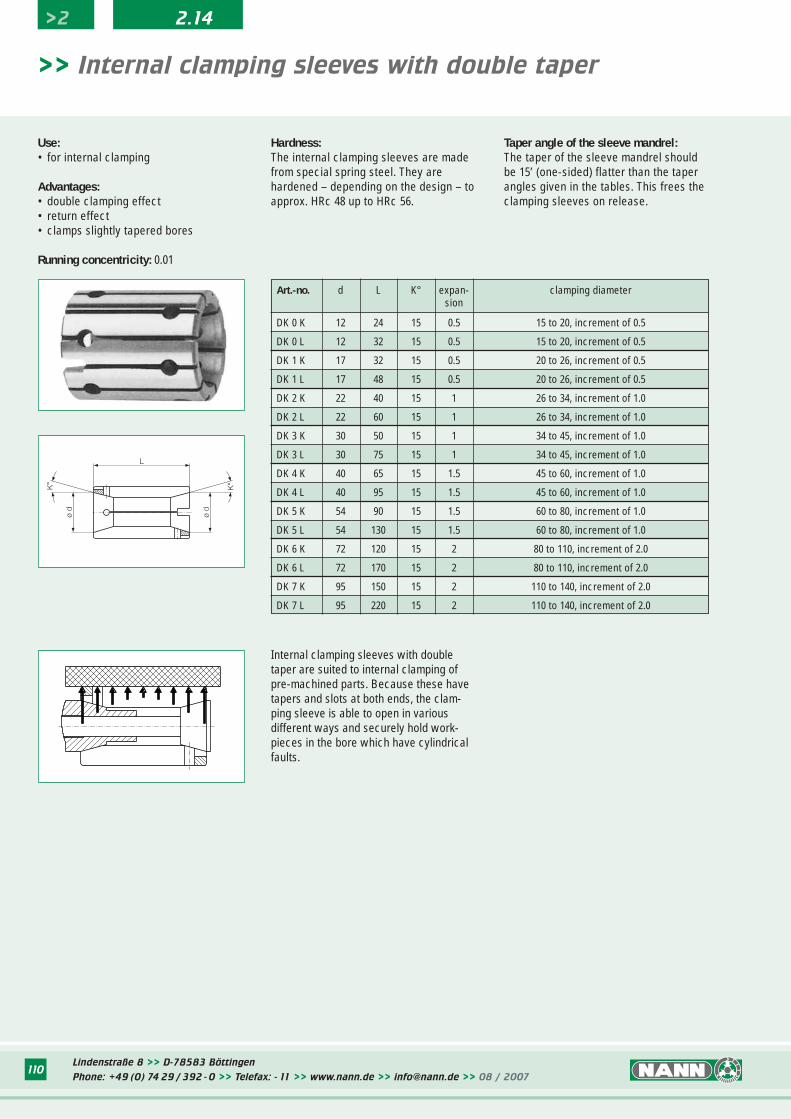
Art.-no. d L K° expan- clamping diametersion
DK 0 K 12 24 15 0.5 15 to 20, increment of 0.5
DK 0 L 12 32 15 0.5 15 to 20, increment of 0.5
DK 1 K 17 32 15 0.5 20 to 26, increment of 0.5
DK 1 L 17 48 15 0.5 20 to 26, increment of 0.5
DK 2 K 22 40 15 1 26 to 34, increment of 1.0
DK 2 L 22 60 15 1 26 to 34, increment of 1.0
DK 3 K 30 50 15 1 34 to 45, increment of 1.0
DK 3 L 30 75 15 1 34 to 45, increment of 1.0
DK 4 K 40 65 15 1.5 45 to 60, increment of 1.0
DK 4 L 40 95 15 1.5 45 to 60, increment of 1.0
DK 5 K 54 90 15 1.5 60 to 80, increment of 1.0
DK 5 L 54 130 15 1.5 60 to 80, increment of 1.0
DK 6 K 72 120 15 2 80 to 110, increment of 2.0
DK 6 L 72 170 15 2 80 to 110, increment of 2.0
DK 7 K 95 150 15 2 110 to 140, increment of 2.0
DK 7 L 95 220 15 2 110 to 140, increment of 2.0
L
ø d
ø d
K°
K°
Use:• for internal clamping
Advantages:• double clamping effect• return effect• clamps slightly tapered bores
Running concentricity: 0.01
Hardness:The internal clamping sleeves are madefrom special spring steel. They are hardened – depending on the design – toapprox. HRc 48 up to HRc 56.
Taper angle of the sleeve mandrel: The taper of the sleeve mandrel shouldbe 15’ (one-sided) flatter than the taperangles given in the tables. This frees theclamping sleeves on release.
>> Internal clamping sleeves with double taper
Internal clamping sleeves with doubletaper are suited to internal clamping ofpre-machined parts. Because these havetapers and slots at both ends, the clam-ping sleeve is able to open in various different ways and securely hold work-pieces in the bore which have cylindricalfaults.
Lindenstraße 8 >> D-78583 Böttingen
Phone: +49 (0) 74 29 / 392 - 0 >> Telefax: - 11 >> www.nann.de >> [email protected] >> 08 / 2007110
111
Art.-no. d L expan- clamping diametersion
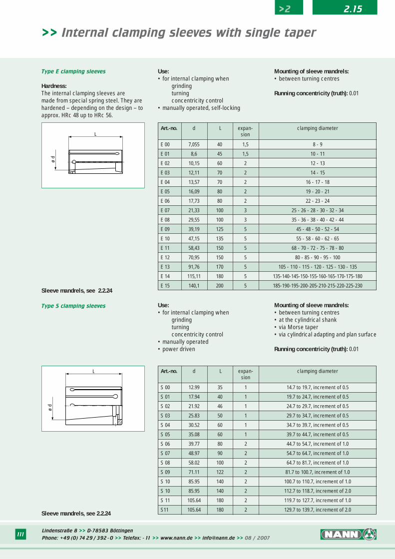
E 00 7,055 40 1,5 8 - 9
E 01 8,6 45 1,5 10 - 11
E 02 10,15 60 2 12 - 13
E 03 12,11 70 2 14 - 15
E 04 13,57 70 2 16 - 17 - 18
E 05 16,09 80 2 19 - 20 - 21
E 06 17,73 80 2 22 - 23 - 24
E 07 21,33 100 3 25 - 26 - 28 - 30 - 32 - 34
E 08 29,55 100 3 35 - 36 - 38 - 40 - 42 - 44
E 09 39,19 125 5 45 - 48 - 50 - 52 - 54
E 10 47,15 135 5 55 - 58 - 60 - 62 - 65
E 11 58,43 150 5 68 - 70 - 72 - 75 - 78 - 80
E 12 70,95 150 5 80 - 85 - 90 - 95 - 100
E 13 91,76 170 5 105 - 110 - 115 - 120 - 125 - 130 - 135
E 14 115,11 180 5 135-140-145-150-155-160-165-170-175-180
E 15 140,1 200 5 185-190-195-200-205-210-215-220-225-230
ø d
L
>> Internal clamping sleeves with single taper
Type E clamping sleeves
Hardness:The internal clamping sleeves are made from special spring steel. They arehardened – depending on the design – toapprox. HRc 48 up to HRc 56.
Use:• for internal clamping when
grindingturningconcentricity control
• manually operated, self-locking
Mounting of sleeve mandrels:• between turning centres
Running concentricity (truth): 0.01
Art.-no. d L expan- clamping diametersion
S 00 12.99 35 1 14.7 to 19.7, increment of 0.5
S 01 17.94 40 1 19.7 to 24.7, increment of 0.5
S 02 21.92 46 1 24.7 to 29.7, increment of 0.5
S 03 25.83 50 1 29.7 to 34.7, increment of 0.5
S 04 30.52 60 1 34.7 to 39.7, increment of 0.5
S 05 35.08 60 1 39.7 to 44.7, increment of 0.5
S 06 39.77 80 2 44.7 to 54.7, increment of 1.0
S 07 48.97 90 2 54.7 to 64.7, increment of 1.0
S 08 58.02 100 2 64.7 to 81.7, increment of 1.0
S 09 71.11 122 2 81.7 to 100.7, increment of 1.0
S 10 85.95 140 2 100.7 to 110.7, increment of 1.0
S 10 85.95 140 2 112.7 to 118.7, increment of 2.0
S 11 105.64 180 2 119.7 to 127.7, increment of 1.0
S11 105.64 180 2 129.7 to 139.7, increment of 2.0
ø d
L
Type S clamping sleeves Use:• for internal clamping when
grindingturningconcentricity control
• manually operated• power driven
Mounting of sleeve mandrels:• between turning centres• at the cylindrical shank• via Morse taper• via cylindrical adapting and plan surface
Running concentricity (truth): 0.01
Sleeve mandrels, see 2.2.24
Sleeve mandrels, see 2.2.24
>2 2.15
Lindenstraße 8 >> D-78583 Böttingen
Phone: +49 (0) 74 29 / 392 - 0 >> Telefax: - 11 >> www.nann.de >> [email protected] >> 08 / 2007111
Lindenstraße 8 >> D-78583 Böttingen
Phone: +49 (0) 74 29 / 392 - 0 >> Telefax: - 11 >> www.nann.de >> [email protected] >> 08 / 2007112
>2 2.15
ø d
ø D
L
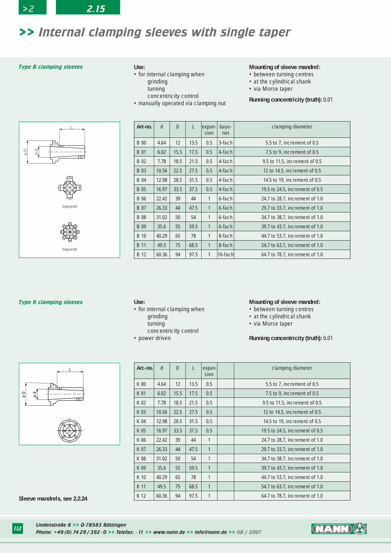
>> Internal clamping sleeves with single taper
Art.-no. d D L expan- clamping diametersion
K 00 4.64 12 13.5 0.5 5.5 to 7, increment of 0.5
K 01 6.02 15.5 17.5 0.5 7.5 to 9, increment of 0.5
K 02 7.78 18.5 21.5 0.5 9.5 to 11.5, increment of 0.5
K 03 10.56 22.5 27.5 0.5 12 to 14.5, increment of 0.5
K 04 12.98 28.5 31.5 0.5 14.5 to 19, increment of 0.5
K 05 16.97 33.5 37.5 0.5 19.5 to 24.5, increment of 0.5
K 06 22.42 39 44 1 24.7 to 28.7, increment of 1.0
K 07 26.33 44 47.5 1 29.7 to 33.7, increment of 1.0
K 08 31.02 50 54 1 34.7 to 38.7, increment of 1.0
K 09 35.6 55 59.5 1 39.7 to 43.7, increment of 1.0
K 10 40.29 65 78 1 44.7 to 53.7, increment of 1.0
K 11 49.5 75 68.5 1 54.7 to 63.7, increment of 1.0
K 12 60.36 94 97.5 1 64.7 to 78.7, increment of 1.0
Type K clamping sleeves Use:• for internal clamping when
grindingturningconcentricity control
• power driven
Mounting of sleeve mandrel:• between turning centres• at the cylindrical shank• via Morse taper
Running concentricity (truth): 0.01
Art-no. d D L expan- bayo- clamping diametersion net
B 00 4.64 12 13.5 0.5 3-fach 5.5 to 7, increment of 0.5
B 01 6.02 15.5 17.5 0.5 4-fach 7.5 to 9, increment of 0.5
B 02 7.78 18.5 21.5 0.5 4-fach 9.5 to 11.5, increment of 0.5
B 03 10.56 22.5 27.5 0.5 4-fach 12 to 14.5, increment of 0.5
B 04 12.98 28.5 31.5 0.5 4-fach 14.5 to 19, increment of 0.5
B 05 16.97 33.5 37.5 0.5 4-fach 19.5 to 24.5, increment of 0.5
B 06 22.42 39 44 1 6-fach 24.7 to 28.7, increment of 1.0
B 07 26.33 44 47.5 1 6-fach 29.7 to 33.7, increment of 1.0
B 08 31.02 50 54 1 6-fach 34.7 to 38.7, increment of 1.0
B 09 35.6 55 59.5 1 6-fach 39.7 to 43.7, increment of 1.0
B 10 40.29 65 78 1 8-fach 44.7 to 53.7, increment of 1.0
B 11 49.5 75 68.5 1 8-fach 54.7 to 63.7, increment of 1.0
B 12 60.36 94 97.5 1 10-fach 64.7 to 78.7, increment of 1.0
ø d
ø D
L
bayonet
bayonet
Type B clamping sleeves Use:• for internal clamping when
grindingturningconcentricity control
• manually operated via clamping nut
Mounting of sleeve mandrel:• between turning centres• at the cylindrical shank• via Morse taper
Running concentricity (truth): 0.01
Sleeve mandrels, see 2.2.24
113Lindenstraße 8 >> D-78583 Böttingen
Phone: +49 (0) 74 29 / 392 - 0 >> Telefax: - 11 >> www.nann.de >> [email protected] >> 08 / 2007
>2 2.16
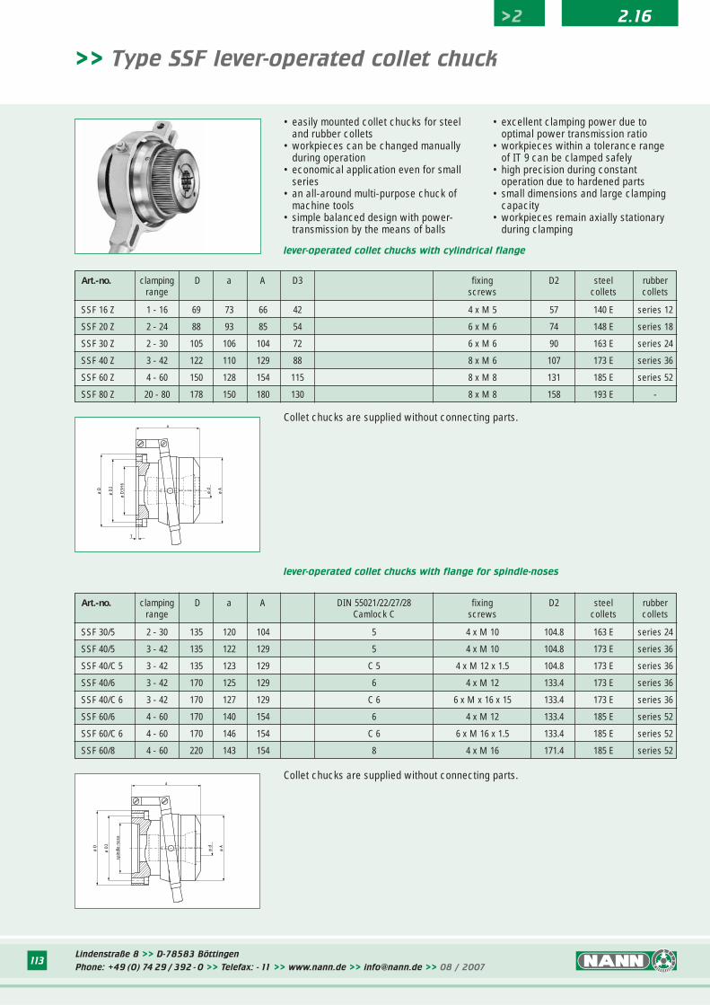
>> Type SSF lever-operated collet chuck
• easily mounted collet chucks for steel and rubber collets
• workpieces can be changed manually during operation
• economical application even for small series
• an all-around multi-purpose chuck of machine tools
• simple balanced design with power-transmission by the means of balls
Art.-no. clamping D a A DIN 55021/22/27/28 fixing D2 steel rubberrange Camlock C screws collets collets
SSF 30/5 2 - 30 135 120 104 5 4 x M 10 104.8 163 E series 24
SSF 40/5 3 - 42 135 122 129 5 4 x M 10 104.8 173 E series 36
SSF 40/C 5 3 - 42 135 123 129 C 5 4 x M 12 x 1.5 104.8 173 E series 36
SSF 40/6 3 - 42 170 125 129 6 4 x M 12 133.4 173 E series 36
SSF 40/C 6 3 - 42 170 127 129 C 6 6 x M x 16 x 15 133.4 173 E series 36
SSF 60/6 4 - 60 170 140 154 6 4 x M 12 133.4 185 E series 52
SSF 60/C 6 4 - 60 170 146 154 C 6 6 x M 16 x 1.5 133.4 185 E series 52
SSF 60/8 4 - 60 220 143 154 8 4 x M 16 171.4 185 E series 52
lever-operated collet chucks with flange for spindle-noses
ø D
ø D
3H6
ø D
2
a
ø A
ø d
T
Art.-no. clamping D a A D3 fixing D2 steel rubberrange screws collets collets
SSF 16 Z 1 - 16 69 73 66 42 4 x M 5 57 140 E series 12
SSF 20 Z 2 - 24 88 93 85 54 6 x M 6 74 148 E series 18
SSF 30 Z 2 - 30 105 106 104 72 6 x M 6 90 163 E series 24
SSF 40 Z 3 - 42 122 110 129 88 8 x M 6 107 173 E series 36
SSF 60 Z 4 - 60 150 128 154 115 8 x M 8 131 185 E series 52
SSF 80 Z 20 - 80 178 150 180 130 8 x M 8 158 193 E -
ø D
spin
dle-
nose
ø D
2
a
ø A
ø d
Collet chucks are supplied without connecting parts.
Collet chucks are supplied without connecting parts.
• excellent clamping power due to optimal power transmission ratio
• workpieces within a tolerance rangeof IT 9 can be clamped safely
• high precision during constant operation due to hardened parts
• small dimensions and large clamping capacity
• workpieces remain axially stationary during clamping
lever-operated collet chucks with cylindrical flange
Lindenstraße 8 >> D-78583 Böttingen
Phone: +49 (0) 74 29 / 392 - 0 >> Telefax: - 11 >> www.nann.de >> [email protected] >> 08 / 2007114
>2 2.17
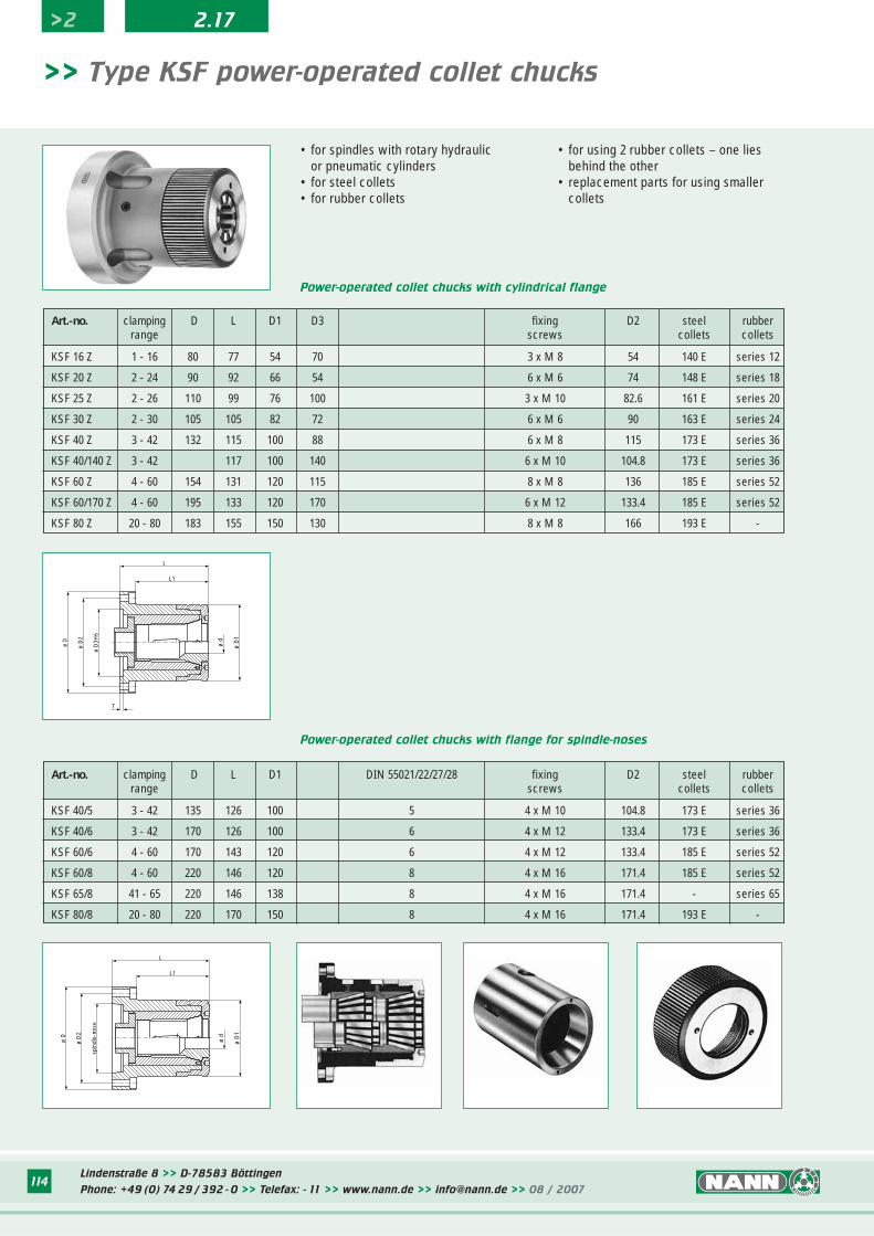
>> Type KSF power-operated collet chucks
• for spindles with rotary hydraulicor pneumatic cylinders
• for steel collets• for rubber collets
• for using 2 rubber collets – one lies behind the other
• replacement parts for using smaller collets
Power-operated collet chucks with flange for spindle-noses
Power-operated collet chucks with cylindrical flange
Art.-no. clamping D L D1 D3 fixing D2 steel rubberrange screws collets collets
KSF 16 Z 1 - 16 80 77 54 70 3 x M 8 54 140 E series 12
KSF 20 Z 2 - 24 90 92 66 54 6 x M 6 74 148 E series 18
KSF 25 Z 2 - 26 110 99 76 100 3 x M 10 82.6 161 E series 20
KSF 30 Z 2 - 30 105 105 82 72 6 x M 6 90 163 E series 24
KSF 40 Z 3 - 42 132 115 100 88 6 x M 8 115 173 E series 36
KSF 40/140 Z 3 - 42 117 100 140 6 x M 10 104.8 173 E series 36
KSF 60 Z 4 - 60 154 131 120 115 8 x M 8 136 185 E series 52
KSF 60/170 Z 4 - 60 195 133 120 170 6 x M 12 133.4 185 E series 52
KSF 80 Z 20 - 80 183 155 150 130 8 x M 8 166 193 E -
Art.-no. clamping D L D1 DIN 55021/22/27/28 fixing D2 steel rubberrange screws collets collets
KSF 40/5 3 - 42 135 126 100 5 4 x M 10 104.8 173 E series 36
KSF 40/6 3 - 42 170 126 100 6 4 x M 12 133.4 173 E series 36
KSF 60/6 4 - 60 170 143 120 6 4 x M 12 133.4 185 E series 52
KSF 60/8 4 - 60 220 146 120 8 4 x M 16 171.4 185 E series 52
KSF 65/8 41 - 65 220 146 138 8 4 x M 16 171.4 - series 65
KSF 80/8 20 - 80 220 170 150 8 4 x M 16 171.4 193 E -
ø D
ø D
3H6
ø D
2
L1
L
ø D
1
ø d
T
ø D
spin
dle-
nose
ø D
2
L1
L
ø D
1
ø d
Lindenstraße 8 >> D-78583 Böttingen
Phone: +49 (0) 74 29 / 392 - 0 >> Telefax: - 11 >> www.nann.de >> [email protected] >> 08 / 2007115
>2 2.17
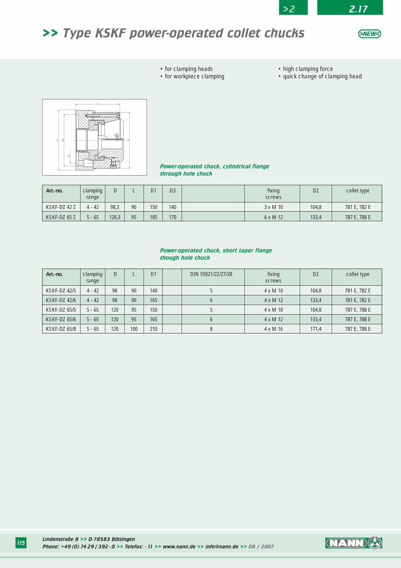
>> Type KSKF power-operated collet chucks
• for clamping heads • for workpiece clamping
• high clamping force• quick change of clamping head
Power-operated chuck, cylindrical flange
through hole chuck
Art.-no. clamping D L D1 D3 fixing D2 collet typerange screws
KSKF-DZ 42 Z 4 - 42 98,3 90 150 140 3 x M 10 104,8 781 E, 782 E
KSKF-DZ 65 Z 5 - 65 120,3 95 185 170 6 x M 12 133,4 787 E, 788 E
Power-operated chuck, short taper flange
though hole chuck
Art.-no. clamping D L D1 DIN 55021/22/27/28 fixing D2 collet typerange screws
KSKF-DZ 42/5 4 - 42 98 90 140 5 4 x M 10 104,8 781 E, 782 E
KSKF-DZ 42/6 4 - 42 98 90 165 6 4 x M 12 133,4 781 E, 782 E
KSKF-DZ 65/5 5 - 65 120 95 150 5 4 x M 10 104,8 787 E, 788 E
KSKF-DZ 65/6 5 - 65 120 95 165 6 4 x M 12 133,4 787 E, 788 E
KSKF-DZ 65/8 5 - 65 120 100 210 8 4 x M 16 171,4 787 E, 788 E
DD1
D3
D2
L

Lindenstraße 8 >> D-78583 Böttingen
Phone: +49 (0) 74 29 / 392 - 0 >> Telefax: - 11 >> www.nann.de >> [email protected] >> 08 / 2007116
>2 2.18
>> Type KSKF power-operated collet chucks
Power-operated chuck, cylindrical flange
Endstop chuck
Art.-no. clamping D L D1 D3 fixing D2 collet tpyerange screws
KSKF-AZ 42 Z 4 - 42 98 126 150 140 3 x M 10 104,8 781 E, 782 E
KSKF-AZ 65 Z 5 - 65 120 130 185 170 6 x M 12 133,4 787 E, 788 E
Power-operated chuck, short taper flange
Endstop chuck
Art.-no. clamping D L D1 DIN 55021/22/27/28 fixing D2 collet typerange screws
KSKF-AZ 42/5 4 - 42 98 121 140 5 4 x M 10 104,8 781 E, 782 E
KSKF-AZ 42/6 4 - 42 98 121 165 6 4 x M 12 133,4 781 E, 782 E
KSKF-AZ 65/5 5 - 65 120 130 155 5 4 x M 10 104,8 787 E, 788 E
KSKF-AZ 65/6 5 - 65 120 130 165 6 4 x M 12 133,4 787 E, 788 E
KSKF-AZ 65/8 5 - 65 120 135 210 8 4 x M 16 171,4 787 E, 788 E
Power-operated chuck, short taper flange
Endstop chuck, fixed clamping head
Art.-no. clamping D L D1 DIN 55021/22/27/28 fixing D2 collet typerange screws
KSKF-AF 42/5 4 - 42 135 120 135 5 4 x M 10 104,8 781 E, 782 E
KSKF-AF 65/6 5 - 65 161 106 160 6 4 x M 12 133,4 787 E, 788 E
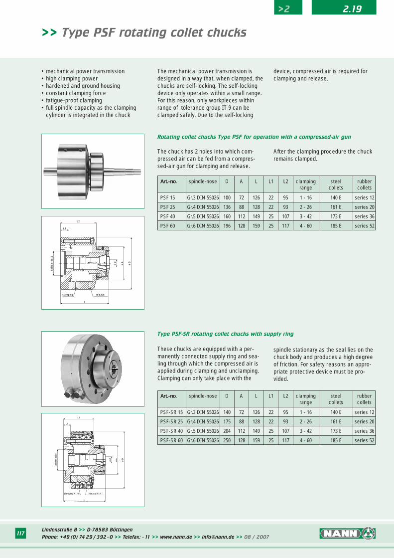
>> Type PSF rotating collet chucks
• mechanical power transmission • high clamping power• hardened and ground housing• constant clamping force• fatigue-proof clamping• full spindle capacity as the clamping
cylinder is integrated in the chuck
The mechanical power transmission isdesigned in a way that, when clamped, thechucks are self-locking. The self-lockingdevice only operates within a small range.For this reason, only workpieces withinrange of tolerance group IT 9 can beclamped safely. Due to the self-locking
device, compressed air is required forclamping and release.
The chuck has 2 holes into which com-pressed air can be fed from a compres-sed-air gun for clamping and release.
Rotating collet chucks Type PSF for operation with a compressed-air gun
After the clamping procedure the chuckremains clamped.
Art.-no. spindle-nose D A L L1 L2 clamping steel rubberrange collets collets
PSF 15 Gr.3 DIN 55026 100 72 126 22 95 1 - 16 140 E series 12
PSF 25 Gr.4 DIN 55026 136 88 128 22 93 2 - 26 161 E series 20
PSF 40 Gr.5 DIN 55026 160 112 149 25 107 3 - 42 173 E series 36
PSF 60 Gr.6 DIN 55026 196 128 159 25 117 4 - 60 185 E series 52
These chucks are equipped with a per-manently connected supply ring and sea-ling through which the compressed air isapplied during clamping and unclamping.Clamping can only take place with the
Type PSF-SR rotating collet chucks with supply ring
spindle stationary as the seal lies on thechuck body and produces a high degreeof friction. For safety reasons an appro-priate protective device must be pro-vided.
Art.-no. spindle-nose D A L L1 L2 clamping steel rubberrange collets collets
PSF-SR 15 Gr.3 DIN 55026 140 72 126 22 95 1 - 16 140 E series 12
PSF-SR 25 Gr.4 DIN 55026 175 88 128 22 93 2 - 26 161 E series 20
PSF-SR 40 Gr.5 DIN 55026 204 112 149 25 107 3 - 42 173 E series 36
PSF-SR 60 Gr.6 DIN 55026 250 128 159 25 117 4 - 60 185 E series 52
spin
dle-
nose
ø d
ø A
ø D
L2
L1
L
clamping release
spin
dle-
nose
L2
L1
L
release R1/4"clamping R1/4"
ø d
ø A
ø D
Lindenstraße 8 >> D-78583 Böttingen
Phone: +49 (0) 74 29 / 392 - 0 >> Telefax: - 11 >> www.nann.de >> [email protected] >> 08 / 2007117
>2 2.19
Lindenstraße 8 >> D-78583 Böttingen
Phone: +49 (0) 74 29 / 392 - 0 >> Telefax: - 11 >> www.nann.de >> [email protected] >> 08 / 2007118
>2 2.19
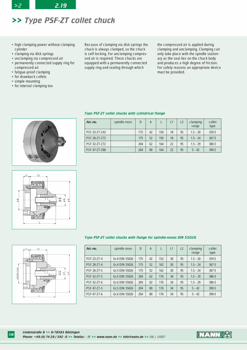
>> Type PSF-ZT collet chuck
• high clamping power without clampingcylinder
• clamping via disk springs• unclamping via compressed air• permanently connected supply ring for
compressed air• fatigue-proof clamping• for drawback collets• simple mounting• for internal clamping too
Because of clamping via disk springs thechuck is always clamped, so the chuckis self-locking. For unclamping compres-sed air is required. These chucks areequipped with a permanently connectedsupply ring and sealing through which
the compressed air is applied duringclamping and unclamping. Clamping canonly take place with the spindle station-ary as the seal lies on the chuck bodyand produces a high degree of friction.For safety reasons an appropriate devicemust be provided.
Art.-no. spindle-nose D A L L1 L2 clamping colletrange type
PSF 23-ZT-Z42 175 42 150 18 95 1.5 - 20 359 E
PSF 28-ZT-Z72 175 52 150 18 95 1.5 - 24 367 E
PSF 32-ZT-Z72 204 62 164 22 95 1.5 - 29 386 E
PSF 47-ZT-Z88 204 80 164 22 95 5 - 42 390 E
Type PSF-ZT collet chucks with cylindrical flange
Type PSF-ZT collet chucks with flange for spindle-noses DIN 55026
Art.-no. spindle-nose D A L L1 L2 clamping colletrange type
PSF 23-ZT-4 Gr.4 DIN 55026 175 42 152 30 95 1.5 - 20 359 E
PSF 28-ZT-4 Gr.4 DIN 55026 175 52 162 30 95 1.5 - 24 367 E
PSF 28-ZT-5 Gr.5 DIN 55026 175 52 162 30 95 1.5 - 24 367 E
PSF 32-ZT-5 Gr.5 DIN 55026 204 62 176 34 95 1.5 - 29 386 E
PSF 32-ZT-6 Gr.6 DIN 55026 204 62 176 34 95 1.5 - 29 386 E
PSF 47-ZT-5 Gr.5 DIN 55026 204 80 176 34 95 5 - 42 390 E
PSF 47-ZT-6 Gr.6 DIN 55026 204 80 176 34 95 5 - 42 390 E
ø A
ø d
L2L1
ø D
L
ø B
ø A
ø d
L2L1
ø D
L
spin
dle-
nose
Lindenstraße 8 >> D-78583 Böttingen
Phone: +49 (0) 74 29 / 392 - 0 >> Telefax: - 11 >> www.nann.de >> [email protected] >> 08 / 2007118
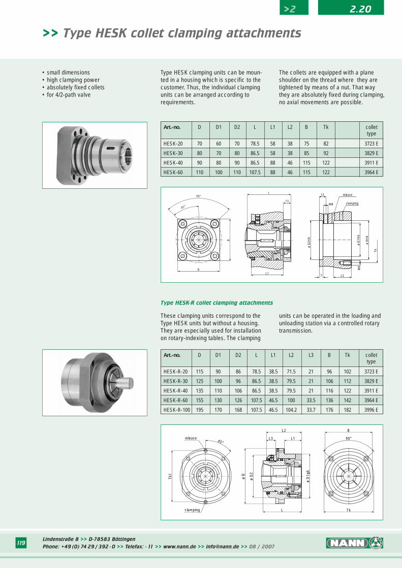
119
>> Type HESK collet clamping attachments
• small dimensions• high clamping power• absolutely fixed collets• for 4/2-path valve
Type HESK clamping units can be moun-ted in a housing which is specific to thecustomer. Thus, the individual clampingunits can be arranged according torequirements.
The collets are equipped with a planeshoulder on the thread where they aretightened by means of a nut. That waythey are absolutely fixed during clamping,no axial movements are possible.
These clamping units correspond to theType HESK units but without a housing.They are especially used for installationon rotary-indexing tables. The clamping
Type HESK-R collet clamping attachments
units can be operated in the loading andunloading station via a controlled rotarytransmission.
L3 L1
L2
ø D
ø D
2
L
ø D
1g6
B
90°
Tkclamping
Tk1
release45°
Art.-no. D D1 D2 L L1 L2 L3 B Tk collettype
HESK-R-20 115 90 86 78.5 38.5 71.5 21 96 102 3723 E
HESK-R-30 125 100 96 86.5 38.5 79.5 21 106 112 3829 E
HESK-R-40 135 110 106 86.5 38.5 79.5 21 116 122 3911 E
HESK-R-60 155 130 126 107.5 46.5 100 33.5 136 142 3964 E
HESK-R-100 195 170 168 107.5 46.5 104.2 33.7 176 182 3996 E
B
B
90°
45°
13
L
L1
ø D
2H9
ø D
1H6
ø D
H6
Tk
M8
L27
M8
12 release
clamping
>2 2.20
Art.-no. D D1 D2 L L1 L2 B Tk collettype
HESK-20 70 60 70 78.5 58 38 75 82 3723 E
HESK-30 80 70 80 86.5 58 38 85 92 3829 E
HESK-40 90 80 90 86.5 88 46 115 122 3911 E
HESK-60 110 100 110 107.5 88 46 115 122 3964 E
Lindenstraße 8 >> D-78583 Böttingen
Phone: +49 (0) 74 29 / 392 - 0 >> Telefax: - 11 >> www.nann.de >> [email protected] >> 08 / 2007119
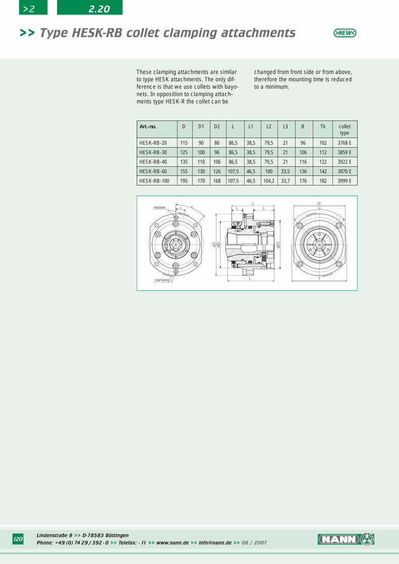
Lindenstraße 8 >> D-78583 Böttingen
Phone: +49 (0) 74 29 / 392 - 0 >> Telefax: - 11 >> www.nann.de >> [email protected] >> 08 / 2007120
>2 2.20
>> Type HESK-RB collet clamping attachments
These clamping attachments are similarto type HESK attachments. The only dif-ference is that we use collets with bayo-nets. In opposition to clamping attach-ments type HESK-R the collet can be
changed from front side or from above,therefore the mounting time is reducedto a minimum.
Art.-no. D D1 D2 L L1 L2 L3 B Tk collettype
HESK-RB-20 115 90 86 86,5 38,5 79,5 21 96 102 3768 E
HESK-RB-30 125 100 96 86,5 38,5 79,5 21 106 112 3859 E
HESK-RB-40 135 110 106 86,5 38,5 79,5 21 116 122 3922 E
HESK-RB-60 155 130 126 107,5 46,5 100 33,5 136 142 3970 E
HESK-RB-100 195 170 168 107,5 46,5 104,2 33,7 176 182 3999 E
clamping
releaseL
øD
41øD
L 9
TøD
1
L
L
D
Lindenstraße 8 >> D-78583 Böttingen
Phone: +49 (0) 74 29 / 392 - 0 >> Telefax: - 11 >> www.nann.de >> [email protected] >> 08 / 2007120
121
>> Type HESK-SK-Z collet clamping attachments
These clamping attachments are similarto type HESK-SK chucks. The only diffe-rence is, that the standard SK clampinghead isn’t fixed, there is a axial move-
ment of the clamping head. While clam-ping the workpiece is drawn into thechuck. The clamping heads can be chan-ged from the front side or from above,
therefore the mounting time is reduced toa minimum.
>2 2.20
Art.-no. D D1 D2 L L1 L2 B Tk collettype
HESK-SK-Z-65 165 140 136 107,5 46,5 41 146 152 787 E, 788 E
>> Type HESK-SK collet clamping attachments
SK clamping heads. The clamping headis absolutely fixed, there is no axialmovement. The clamping heads can be
changed from the front side or fromabove, therefore the mounting time isreduced to a minimum.
Art.-no. D D1 D2 L L1 L2 L3 B Tk collettype
HESK-SK-65 165 140 136 107,5 46,5 100 33,5 146 152 787 E, 788 E
These clamping attachments are similarto type HESK-R or HESK-RB chucks. Thedifference only is that we use standard
clamping??
release
?
?
release
clamping
Lindenstraße 8 >> D-78583 Böttingen
Phone: +49 (0) 74 29 / 392 - 0 >> Telefax: - 11 >> www.nann.de >> [email protected] >> 08 / 2007121
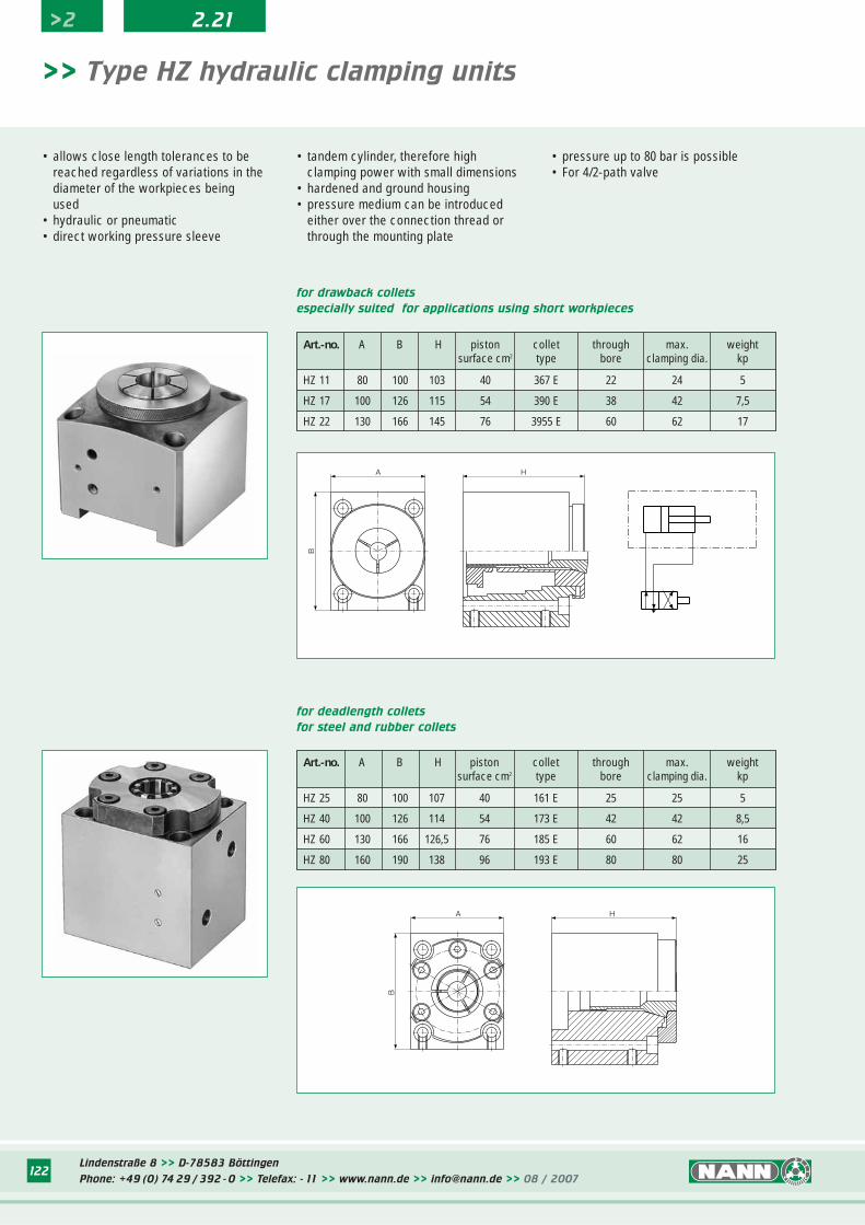
>2 2.21
Lindenstraße 8 >> D-78583 Böttingen
Phone: +49 (0) 74 29 / 392 - 0 >> Telefax: - 11 >> www.nann.de >> [email protected] >> 08 / 2007122
>> Type HZ hydraulic clamping units
• tandem cylinder, therefore high clamping power with small dimensions
• hardened and ground housing• pressure medium can be introduced
either over the connection thread or through the mounting plate
• pressure up to 80 bar is possible• For 4/2-path valve
Art.-no. A B H piston collet through max. weightsurface cm2 type bore clamping dia. kp
HZ 11 80 100 103 40 367 E 22 24 5
HZ 17 100 126 115 54 390 E 38 42 7,5
HZ 22 130 166 145 76 3955 E 60 62 17
for drawback collets
especially suited for applications using short workpieces
Art.-no. A B H piston collet through max. weightsurface cm2 type bore clamping dia. kp
HZ 25 80 100 107 40 161 E 25 25 5
HZ 40 100 126 114 54 173 E 42 42 8,5
HZ 60 130 166 126,5 76 185 E 60 62 16
HZ 80 160 190 138 96 193 E 80 80 25
for deadlength collets
for steel and rubber collets
• allows close length tolerances to be reached regardless of variations in the diameter of the workpieces being used
• hydraulic or pneumatic• direct working pressure sleeve
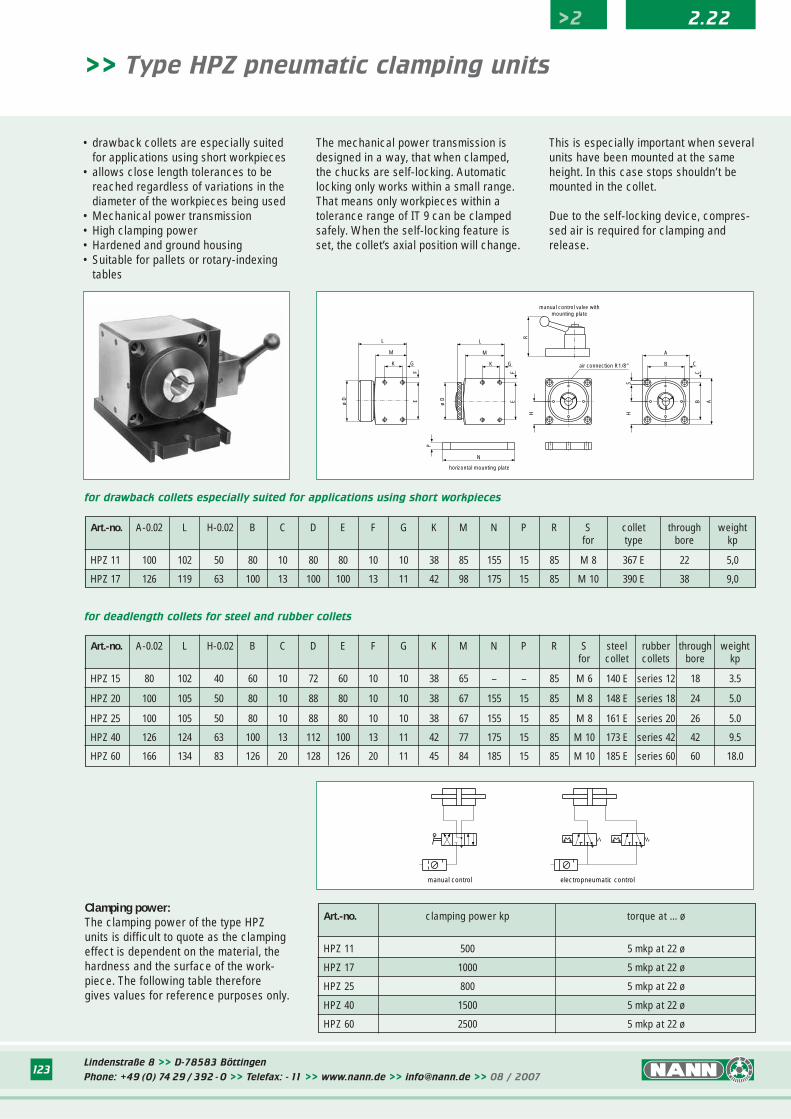
Lindenstraße 8 >> D-78583 Böttingen
Phone: +49 (0) 74 29 / 392 - 0 >> Telefax: - 11 >> www.nann.de >> [email protected] >> 08 / 2007123
• drawback collets are especially suited for applications using short workpieces
• allows close length tolerances to be reached regardless of variations in the diameter of the workpieces being used
• Mechanical power transmission• High clamping power• Hardened and ground housing• Suitable for pallets or rotary-indexing
tables
The mechanical power transmission isdesigned in a way, that when clamped,the chucks are self-locking. Automaticlocking only works within a small range.That means only workpieces within atolerance range of IT 9 can be clampedsafely. When the self-locking feature isset, the collet’s axial position will change.
>> Type HPZ pneumatic clamping units
Art.-no. A-0.02 L H-0.02 B C D E F G K M N P R S collet through weightfor type bore kp
HPZ 11 100 102 50 80 10 80 80 10 10 38 85 155 15 85 M 8 367 E 22 5,0
HPZ 17 126 119 63 100 13 100 100 13 11 42 98 175 15 85 M 10 390 E 38 9,0
for drawback collets especially suited for applications using short workpieces
for deadlength collets for steel and rubber collets
Clamping power:The clamping power of the type HPZunits is difficult to quote as the clampingeffect is dependent on the material, thehardness and the surface of the work-piece. The following table thereforegives values for reference purposes only.
Art.-no. clamping power kp torque at ... ø
HPZ 11 500 5 mkp at 22 ø
HPZ 17 1000 5 mkp at 22 ø
HPZ 25 800 5 mkp at 22 ø
HPZ 40 1500 5 mkp at 22 ø
HPZ 60 2500 5 mkp at 22 ø
Art.-no. A-0.02 L H-0.02 B C D E F G K M N P R S steel rubber through weightfor collet collets bore kp
HPZ 15 80 102 40 60 10 72 60 10 10 38 65 – – 85 M 6 140 E series 12 18 3.5
HPZ 20 100 105 50 80 10 88 80 10 10 38 67 155 15 85 M 8 148 E series 18 24 5.0
HPZ 25 100 105 50 80 10 88 80 10 10 38 67 155 15 85 M 8 161 E series 20 26 5.0
HPZ 40 126 124 63 100 13 112 100 13 11 42 77 175 15 85 M 10 173 E series 42 42 9.5
HPZ 60 166 134 83 126 20 128 126 20 11 45 84 185 15 85 M 10 185 E series 60 60 18.0
This is especially important when severalunits have been mounted at the sameheight. In this case stops shouldn’t bemounted in the collet.
Due to the self-locking device, compres-sed air is required for clamping andrelease.
>2 2.22
R
manual control valve with�mounting plate
air connection R1/8"
B A
C
B
A
C
SHH
horizontal mounting plate
N
P
L
M
K G
EF
ø D
ø D
L
M
K G
EF
manual control electropneumatic control
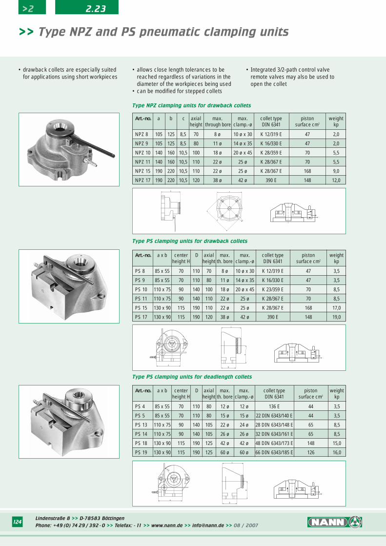
Lindenstraße 8 >> D-78583 Böttingen
Phone: +49 (0) 74 29 / 392 - 0 >> Telefax: - 11 >> www.nann.de >> [email protected] >> 08 / 2007124
>2 2.23
>> Type NPZ and PS pneumatic clamping units
• drawback collets are especially suited for applications using short workpieces
• allows close length tolerances to be reached regardless of variations in the diameter of the workpieces being used
• can be modified for stepped collets
Art.-no. a b c axial max. max. collet type piston weightheight through bore clamp.-ø DIN 6341 surface cm2 kp
NPZ 8 105 125 8,5 70 8 ø 10 ø x 30 K 12/319 E 47 2,0
NPZ 9 105 125 8,5 80 11 ø 14 ø x 35 K 16/330 E 47 2,0
NPZ 10 140 160 10,5 100 18 ø 20 ø x 45 K 28/359 E 70 5,5
NPZ 11 140 160 10,5 110 22 ø 25 ø K 28/367 E 70 5,5
NPZ 15 190 220 10,5 110 22 ø 25 ø K 28/367 E 168 9,0
NPZ 17 190 220 10,5 120 38 ø 42 ø 390 E 148 12,0
Type NPZ clamping units for drawback collets
Type PS clamping units for drawback collets
Art.-no. a x b center D axial max. max. collet type piston weightheight H height th. bore clamp.-ø DIN 6341 surface cm2 kp
PS 8 85 x 55 70 110 70 8 ø 10 ø x 30 K 12/319 E 47 3,5
PS 9 85 x 55 70 110 80 11 ø 14 ø x 35 K 16/330 E 47 3,5
PS 10 110 x 75 90 140 100 18 ø 20 ø x 45 K 23/359 E 70 8,5
PS 11 110 x 75 90 140 110 22 ø 25 ø K 28/367 E 70 8,5
PS 15 130 x 90 115 190 110 22 ø 25 ø K 28/367 E 168 17,0
PS 17 130 x 90 115 190 120 38 ø 42 ø 390 E 148 19,0
Art.-no. a x b center D axial max. max. collet type piston weightheight H height th. bore clamp.-ø DIN 6341 surface cm2 kp
PS 4 85 x 55 70 110 80 12 ø 12 ø 136 E 44 3,5
PS 5 85 x 55 70 110 80 15 ø 15 ø 22 DIN 6343/140 E 44 3,5
PS 13 110 x 75 90 140 105 22 ø 24 ø 28 DIN 6343/148 E 65 8,5
PS 14 110 x 75 90 140 105 26 ø 26 ø 32 DIN 6343/161 E 65 8,5
PS 18 130 x 90 115 190 125 42 ø 42 ø 48 DIN 6343/173 E 148 15,0
PS 19 130 x 90 115 190 125 60 ø 60 ø 66 DIN 6343/185 E 126 16,0
Type PS clamping units for deadlength collets
• Integrated 3/2-path control valveremote valves may also be used to open the collet
H a
cb
a
ø D
L
H
b
a
ø D
L
H
b
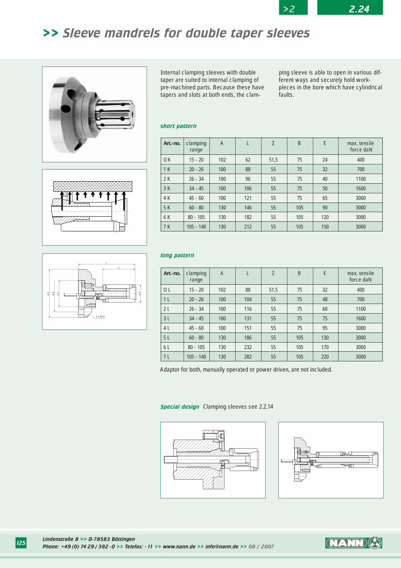
Lindenstraße 8 >> D-78583 Böttingen
Phone: +49 (0) 74 29 / 392 - 0 >> Telefax: - 11 >> www.nann.de >> [email protected] >> 08 / 2007125
>2 2.24
>> Sleeve mandrels for double taper sleeves
Internal clamping sleeves with doubletaper are suited to internal clamping ofpre-machined parts. Because these havetapers and slots at both ends, the clam-
ping sleeve is able to open in various dif-ferent ways and securely hold work-pieces in the bore which have cylindricalfaults.
short pattern
long pattern
ø A
ø B
ø Z
3 x M10
L
E
ø d
Special design Clamping sleeves see 2.2.14
Art.-no. clamping A L Z B E max. tensilerange force daN
O K 15 - 20 102 62 51,5 75 24 400
1 K 20 - 26 100 88 55 75 32 700
2 K 26 - 34 100 96 55 75 40 1100
3 K 34 - 45 100 106 55 75 50 1600
4 K 45 - 60 100 121 55 75 65 3000
5 K 60 - 80 130 146 55 105 90 3000
6 K 80 - 105 130 182 55 105 120 3000
7 K 105 - 140 130 212 55 105 150 3000
Art.-no. clamping A L Z B E max. tensilerange force daN
O L 15 - 20 102 88 51,5 75 32 400
1 L 20 - 26 100 104 55 75 48 700
2 L 26 - 34 100 116 55 75 60 1100
3 L 34 - 45 100 131 55 75 75 1600
4 L 45 - 60 100 151 55 75 95 3000
5 L 60 - 80 130 186 55 105 130 3000
6 L 80 - 105 130 232 55 105 170 3000
7 L 105 - 140 130 282 55 105 220 3000
Adaptor for both, manually operated or power driven, are not included.
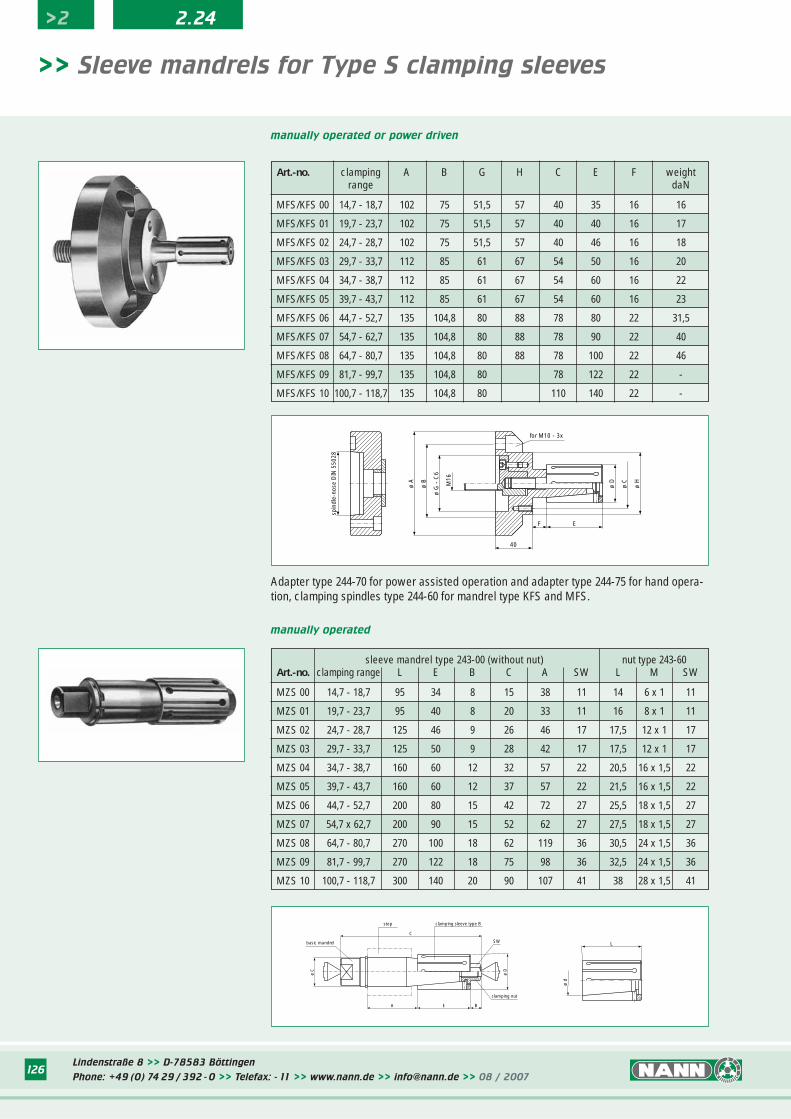
Lindenstraße 8 >> D-78583 Böttingen
Phone: +49 (0) 74 29 / 392 - 0 >> Telefax: - 11 >> www.nann.de >> [email protected] >> 08 / 2007126
>2 2.24
ø A
ø B
ø G
- C
6
M16
for M10 - 3x
ø D
ø C
ø H
F E
40
spin
dle-
nose
DIN
550
28
>> Sleeve mandrels for Type S clamping sleeves
manually operated or power driven
manually operated
sleeve mandrel type 243-00 (without nut) nut type 243-60Art.-no. clamping range L E B C A SW L M SW
MZS 00 14,7 - 18,7 95 34 8 15 38 11 14 6 x 1 11
MZS 01 19,7 - 23,7 95 40 8 20 33 11 16 8 x 1 11
MZS 02 24,7 - 28,7 125 46 9 26 46 17 17,5 12 x 1 17
MZS 03 29,7 - 33,7 125 50 9 28 42 17 17,5 12 x 1 17
MZS 04 34,7 - 38,7 160 60 12 32 57 22 20,5 16 x 1,5 22
MZS 05 39,7 - 43,7 160 60 12 37 57 22 21,5 16 x 1,5 22
MZS 06 44,7 - 52,7 200 80 15 42 72 27 25,5 18 x 1,5 27
MZS 07 54,7 x 62,7 200 90 15 52 62 27 27,5 18 x 1,5 27
MZS 08 64,7 - 80,7 270 100 18 62 119 36 30,5 24 x 1,5 36
MZS 09 81,7 - 99,7 270 122 18 75 98 36 32,5 24 x 1,5 36
MZS 10 100,7 - 118,7 300 140 20 90 107 41 38 28 x 1,5 41
Adapter type 244-70 for power assisted operation and adapter type 244-75 for hand opera-tion, clamping spindles type 244-60 for mandrel type KFS and MFS.
Art.-no. clamping A B G H C E F weightrange daN
MFS/KFS 00 14,7 - 18,7 102 75 51,5 57 40 35 16 16
MFS/KFS 01 19,7 - 23,7 102 75 51,5 57 40 40 16 17
MFS/KFS 02 24,7 - 28,7 102 75 51,5 57 40 46 16 18
MFS/KFS 03 29,7 - 33,7 112 85 61 67 54 50 16 20
MFS/KFS 04 34,7 - 38,7 112 85 61 67 54 60 16 22
MFS/KFS 05 39,7 - 43,7 112 85 61 67 54 60 16 23
MFS/KFS 06 44,7 - 52,7 135 104,8 80 88 78 80 22 31,5
MFS/KFS 07 54,7 - 62,7 135 104,8 80 88 78 90 22 40
MFS/KFS 08 64,7 - 80,7 135 104,8 80 88 78 100 22 46
MFS/KFS 09 81,7 - 99,7 135 104,8 80 78 122 22 -
MFS/KFS 10 100,7 - 118,7 135 104,8 80 110 140 22 -
ø D
SW
ø C
A E B
C
basic mandrel
stop clamping sleeve type B
clamping nut
ø d
L
Lindenstraße 8 >> D-78583 Böttingen
Phone: +49 (0) 74 29 / 392 - 0 >> Telefax: - 11 >> www.nann.de >> [email protected] >> 08 / 2007126
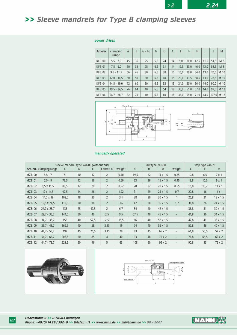
>> Sleeve mandrels for Type B clamping sleeves
manually operated
sleeve mandrel type 241-00 (without nut) nut type 241-60 stop type 241-70Art.-no. clamping range L A E center. B weight G H M weight C F M
MZB 00 5,5 - 7 71 10 12 2 0,40 19,5 22 14 x 1,5 0,25 10,8 8,5 7 x 1
MZB 01 7,5 - 9 79,5 12 16 2 0,60 23 26 16 x 1,5 0,45 13,8 10,5 9 x 1
MZB 02 9,5 x 11,5 89,5 12 20 2 0,92 28 27 20 x 1,5 0,55 16,8 13,2 11 x 1
MZB 03 12 x 14,5 97,5 14 26 2 1,92 31 29 24 x 1,5 0,7 20,8 16 14 x 1
MZB 04 14,5 x 19 102,5 18 30 2 3,1 38 30 30 x 1,5 1 26,8 21 18 x 1,5
MZB 05 19,5 x 24,5 113,5 20 36 2 3,6 47 30 36 x 1,5 1,7 31,8 26 24 x 1,5
MZB 06 24,7 x 28,7 136 25 42,5 2 6,7 54 40 42 x 1,5 - 36,8 31 30 x 1,5
MZB 07 29,7 - 33,7 144,5 30 46 2,5 9,5 57,5 40 45 x 1,5 - 41,8 36 34 x 1,5
MZB 08 34,7 - 38,7 156 40 52,5 2,5 15,5 66 40 52 x 1,5 - 47,8 41 36 x 1,5
MZB 09 39,7 - 43,7 166,5 40 58 3,15 19 74 40 56 x 1,5 - 52,8 46 40 x 1,5
MZB 10 44,7 - 53,7 197 45 76,5 3,15 28 83 45 65 x 2 - 61,8 55,5 52 x 2
MZB 11 54,7 - 63,7 208,5 50 85 4 40 93 48 75 x 2 - 71,8 65,5 62 x 2
MZB 12 64,7 - 78,7 221,5 50 96 5 63 108 50 95 x 2 - 90,8 83 75 x 2
power driven
Art.-no. clamping A B G - h6 N O C E F H J L Mrange
KFB 00 5,5 - 7,0 45 36 25 5,5 24 14 9,0 30,0 42,5 11,5 51,5 M 8
KFB 01 7,5 - 9,0 50 39 25 6,6 31 14 12,5 33,0 46,0 12,0 58,5 M 8
KFB 02 9,5 - 11,5 56 46 30 6,6 38 15 16,0 39,0 54,0 13,0 70,0 M 10
KFB 03 12,0 - 14,5 60 50 30 6,6 40 15 20,0 43,5 58,5 13,0 78,5 M 10
KFB 04 14,5 - 19,0 72 60 30 6,6 52 15 24,0 50,0 66,0 14,0 90,0 M 10
KFB 05 19,5 - 24,5 76 64 40 6,6 54 18 30,0 51,0 67,0 14,0 97,0 M 12
KFB 06 24,7 - 28,7 82 70 40 6,6 60 18 36,0 55,0 71,0 14,0 107,0 M 12
Lindenstraße 8 >> D-78583 Böttingen
Phone: +49 (0) 74 29 / 392 - 0 >> Telefax: - 11 >> www.nann.de >> [email protected] >> 08 / 2007127
>2 2.24
ø A
ø B
ø G
- h
6
M
C H
F
J1.5
E
L
ø O
ø D
ø N
ø d
ø D
L
L
H Ebasic mandrel
ø A
ø G
ø D
clamping nutclamping sleeve type B
stop
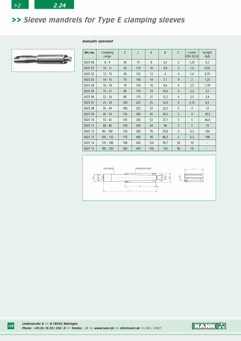
Lindenstraße 8 >> D-78583 Böttingen
Phone: +49 (0) 74 29 / 392 - 0 >> Telefax: - 11 >> www.nann.de >> [email protected] >> 08 / 2007128
>2 2.24
>> Sleeve mandrels for Type E clamping sleeves
manually operated
Art.-no. clamping E L A B C center weightrange DIN 332 B daN
MZE 00 8 - 9 40 75 8 4,2 3 1,25 0,2
MZE 01 10 - 11 43 110 10 4,8 3 1,6 0,55
MZE 02 12 - 13 60 125 12 6 4 1,6 0,75
MZE 03 14 - 15 70 140 14 7,1 4 2 1,25
MZE 04 16 - 18 70 150 16 8,6 4 2,5 1,78
MZE 05 19 - 21 80 170 19 10,5 4 2,5 3,1
MZE 06 22 - 24 80 175 21 12,2 4 2,5 3,4
MZE 07 25 - 34 100 225 25 14,3 4 3,15 6,5
MZE 08 35 - 44 100 225 33 22,5 5 4 12
MZE 09 45 - 54 125 300 45 30,5 5 4 29,3
MZE 10 55 - 65 135 330 53 37,7 5 5 46,6
MZE 11 68 - 80 150 350 64 48 5 5 74
MZE 12 80 - 100 150 350 76 59,8 5 6,3 104
MZE 13 105 - 135 170 400 99 80,3 5 6,3 198
MZE 14 135 - 180 180 420 124 99,7 50 10 -
MZE 15 185 - 230 200 420 150 124 40 10 -
ø d
L
ø A
ø D
ø B
E
L
C
basic mandrel clamping sleeve type E
Lindenstraße 8 >> D-78583 Böttingen
Phone: +49 (0) 74 29 / 392 - 0 >> Telefax: - 11 >> www.nann.de >> [email protected] >> 08 / 2007128
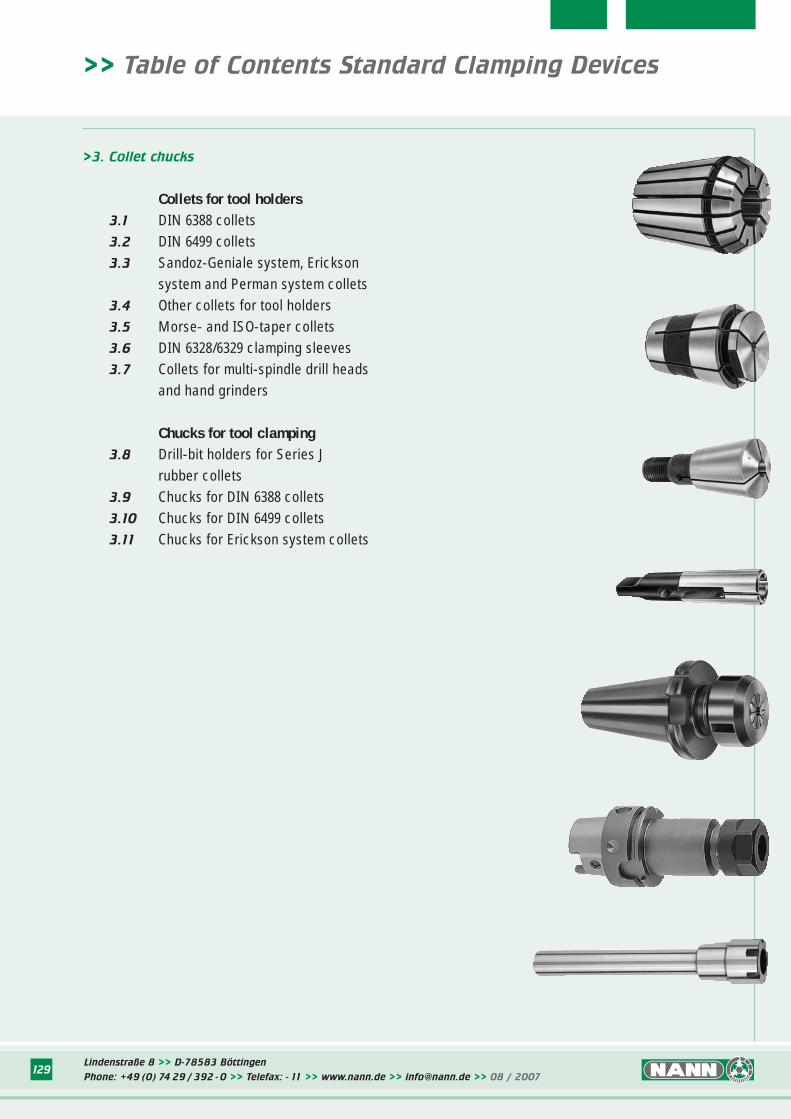
>> Table of Contents Standard Clamping Devices
>3. Collet chucks
Collets for tool holders3.1 DIN 6388 collets3.2 DIN 6499 collets3.3 Sandoz-Geniale system, Erickson
system and Perman system collets3.4 Other collets for tool holders3.5 Morse- and ISO-taper collets3.6 DIN 6328/6329 clamping sleeves3.7 Collets for multi-spindle drill heads
and hand grinders
Chucks for tool clamping3.8 Drill-bit holders for Series J
rubber collets3.9 Chucks for DIN 6388 collets3.10 Chucks for DIN 6499 collets3.11 Chucks for Erickson system collets
Lindenstraße 8 >> D-78583 Böttingen
Phone: +49 (0) 74 29 / 392 - 0 >> Telefax: - 11 >> www.nann.de >> [email protected] >> 08 / 2007129
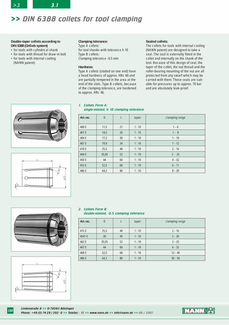
Lindenstraße 8 >> D-78583 Böttingen
Phone: +49 (0) 74 29 / 392 - 0 >> Telefax: - 11 >> www.nann.de >> [email protected] >> 08 / 2007130
1. Collets Form A:
single-slotted, h 10 clamping tolerance
Art.-no. D L taper clamping range
400 E 11,5 21 1 : 10 1 - 6
401 E 14,5 26 1 : 10 1 - 8
404 E 17,2 30 1 : 10 1 - 10
407 E 19,9 34 1 : 10 1 - 12
410 E 25,5 40 1 : 10 2 - 16
444 E 35,05 52 1 : 10 2 - 25
450 E 44 60 1 : 10 4 - 32
453 E 52,5 68 1 : 10 6 - 11
486 E 64,2 80 1 : 10 8 - 29
>> DIN 6388 collets for tool clamping
Double-taper collets according toDIN 6388 (Ortlieb system)• for tools with cylindrical shank• for tools with thread for draw-in bolt• for tools with internal cooling
(NANN patent)
Clamping tolerance:Type A collets:for tool shanks with tolerance h 10Type B collets:Clamping tolerance -0.5 mm
Hardness:Type A collets (slotted on one end) havea head hardness of approx. HRc 60 andare partially tempered in the area at theend of the slots. Type B collets, becauseof the clamping tolerance, are hardenedto approx. HRc 46.
Sealed collets:The collets for tools with internal cooling(NANN patent) are designed to take aseal. The seal is externally fitted in thecollet and internally on the shank of thetool. Because of this design of seal, thetaper of the collet, the nut thread and theroller-bearing mounting of the nut are allprotected from any swarf which may becarried with them. These seals are suit-able for pressures up to approx. 70 barand are absolutely leak-proof.
ø D
30°
K°
L
2. Collets Form B:
double-slotted, -0.5 clamping tolerance
Art.-no. D L taper clamping range
415 E 25,5 40 1 : 10 2 - 16
4541 E 30 45 1 : 10 2 - 20
462 E 35,05 52 1 : 10 2 - 25
467 E 44 60 1 : 10 6 - 32
468 E 52,5 68 1 : 10 12 - 40
486 E 64,2 80 1 : 10 30 - 50
ø D
30°
K°
L
>3 3.1
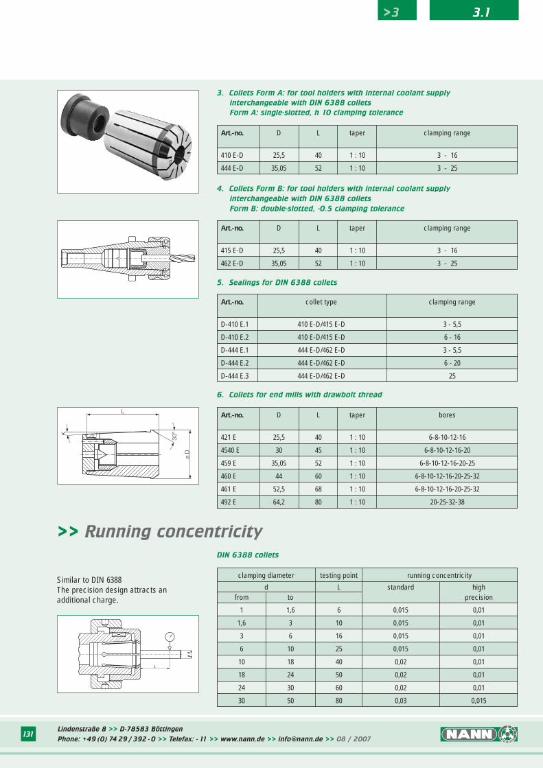
Lindenstraße 8 >> D-78583 Böttingen
Phone: +49 (0) 74 29 / 392 - 0 >> Telefax: - 11 >> www.nann.de >> [email protected] >> 08 / 2007131
3. Collets Form A: for tool holders with internal coolant supply
interchangeable with DIN 6388 collets
Form A: single-slotted, h 10 clamping tolerance
Art.-no. D L taper clamping range
410 E-D 25,5 40 1 : 10 3 - 16
444 E-D 35,05 52 1 : 10 3 - 25
4. Collets Form B: for tool holders with internal coolant supply
interchangeable with DIN 6388 collets
Form B: double-slotted, -0.5 clamping tolerance
Art.-no. D L taper clamping range
415 E-D 25,5 40 1 : 10 3 - 16
462 E-D 35,05 52 1 : 10 3 - 25
Art.-no. collet type clamping range
D-410 E.1 410 E-D/415 E-D 3 - 5,5
D-410 E.2 410 E-D/415 E-D 6 - 16
D-444 E.1 444 E-D/462 E-D 3 - 5,5
D-444 E.2 444 E-D/462 E-D 6 - 20
D-444 E.3 444 E-D/462 E-D 25
5. Sealings for DIN 6388 collets
clamping diameter testing point running concentricity
d L standard highfrom to precision
1 1,6 6 0,015 0,01
1,6 3 10 0,015 0,01
3 6 16 0,015 0,01
6 10 25 0,015 0,01
10 18 40 0,02 0,01
18 24 50 0,02 0,01
24 30 60 0,02 0,01
30 50 80 0,03 0,015
DIN 6388 collets
ø d
L
Similar to DIN 6388The precision design attracts an additional charge.
>> Running concentricity
6. Collets for end mills with drawbolt thread
Art.-no. D L taper bores
421 E 25,5 40 1 : 10 6-8-10-12-16
4540 E 30 45 1 : 10 6-8-10-12-16-20
459 E 35,05 52 1 : 10 6-8-10-12-16-20-25
460 E 44 60 1 : 10 6-8-10-12-16-20-25-32
461 E 52,5 68 1 : 10 6-8-10-12-16-20-25-32
492 E 64,2 80 1 : 10 20-25-32-38
ø D
L
30°K
>3 3.1
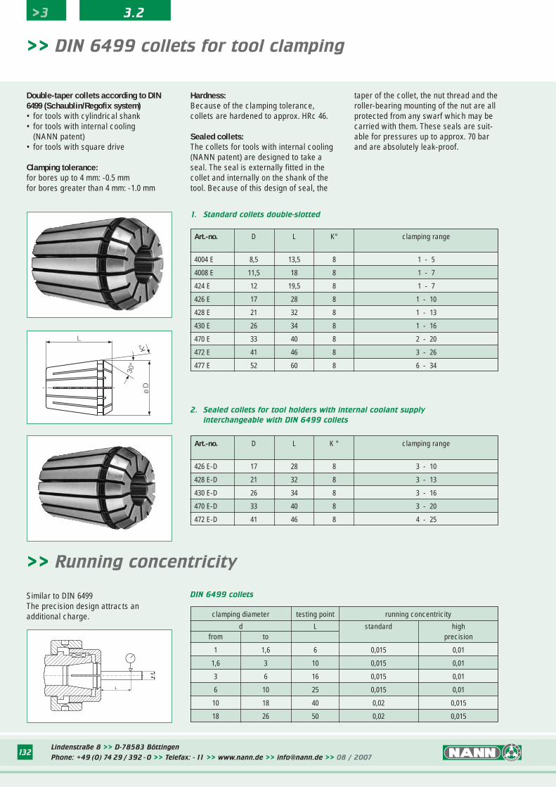
Lindenstraße 8 >> D-78583 Böttingen
Phone: +49 (0) 74 29 / 392 - 0 >> Telefax: - 11 >> www.nann.de >> [email protected] >> 08 / 2007132
1. Standard collets double-slotted
Art.-no. D L K° clamping range
4004 E 8,5 13,5 8 1 - 5
4008 E 11,5 18 8 1 - 7
424 E 12 19,5 8 1 - 7
426 E 17 28 8 1 - 10
428 E 21 32 8 1 - 13
430 E 26 34 8 1 - 16
470 E 33 40 8 2 - 20
472 E 41 46 8 3 - 26
477 E 52 60 8 6 - 34
>> DIN 6499 collets for tool clamping
Double-taper collets according to DIN6499 (Schaublin/Regofix system)• for tools with cylindrical shank• for tools with internal cooling
(NANN patent)• for tools with square drive
Clamping tolerance:for bores up to 4 mm: -0.5 mmfor bores greater than 4 mm: -1.0 mm
Hardness:Because of the clamping tolerance, collets are hardened to approx. HRc 46.
Sealed collets:The collets for tools with internal cooling(NANN patent) are designed to take aseal. The seal is externally fitted in thecollet and internally on the shank of thetool. Because of this design of seal, the
taper of the collet, the nut thread and theroller-bearing mounting of the nut are allprotected from any swarf which may becarried with them. These seals are suit-able for pressures up to approx. 70 barand are absolutely leak-proof.
ø D
30°
K°
L
Art.-no. D L K ° clamping range
426 E-D 17 28 8 3 - 10
428 E-D 21 32 8 3 - 13
430 E-D 26 34 8 3 - 16
470 E-D 33 40 8 3 - 20
472 E-D 41 46 8 4 - 25
2. Sealed collets for tool holders with internal coolant supply
interchangeable with DIN 6499 collets
Similar to DIN 6499The precision design attracts an additional charge. clamping diameter testing point running concentricity
d L standard highfrom to precision
1 1,6 6 0,015 0,01
1,6 3 10 0,015 0,01
3 6 16 0,015 0,01
6 10 25 0,015 0,01
10 18 40 0,02 0,015
18 26 50 0,02 0,015
DIN 6499 collets
>> Running concentricity
L
ø d
>3 3.2
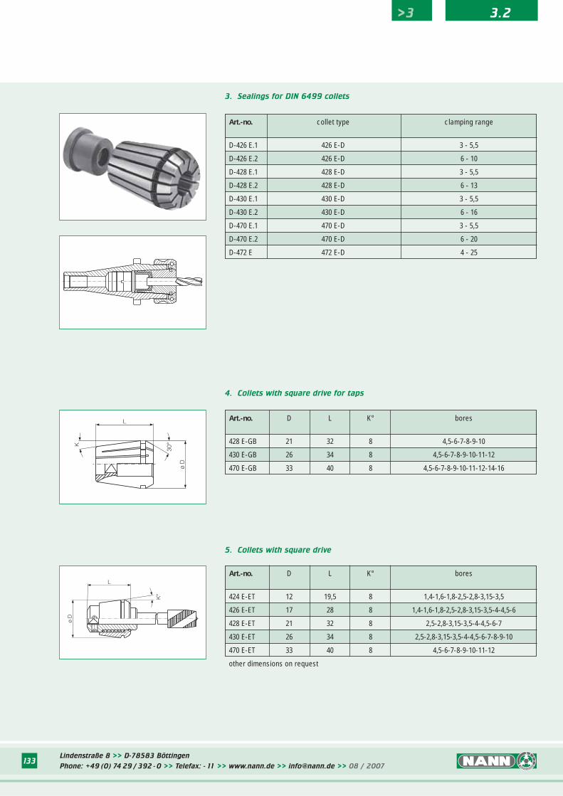
Lindenstraße 8 >> D-78583 Böttingen
Phone: +49 (0) 74 29 / 392 - 0 >> Telefax: - 11 >> www.nann.de >> [email protected] >> 08 / 2007133
Art.-no. collet type clamping range
D-426 E.1 426 E-D 3 - 5,5
D-426 E.2 426 E-D 6 - 10
D-428 E.1 428 E-D 3 - 5,5
D-428 E.2 428 E-D 6 - 13
D-430 E.1 430 E-D 3 - 5,5
D-430 E.2 430 E-D 6 - 16
D-470 E.1 470 E-D 3 - 5,5
D-470 E.2 470 E-D 6 - 20
D-472 E 472 E-D 4 - 25
3. Sealings for DIN 6499 collets
5. Collets with square drive
Art.-no. D L K° bores
424 E-ET 12 19,5 8 1,4-1,6-1,8-2,5-2,8-3,15-3,5
426 E-ET 17 28 8 1,4-1,6-1,8-2,5-2,8-3,15-3,5-4-4,5-6
428 E-ET 21 32 8 2,5-2,8-3,15-3,5-4-4,5-6-7
430 E-ET 26 34 8 2,5-2,8-3,15-3,5-4-4,5-6-7-8-9-10
470 E-ET 33 40 8 4,5-6-7-8-9-10-11-12
other dimensions on request
4. Collets with square drive for taps
Art.-no. D L K° bores
428 E-GB 21 32 8 4,5-6-7-8-9-10
430 E-GB 26 34 8 4,5-6-7-8-9-10-11-12
470 E-GB 33 40 8 4,5-6-7-8-9-10-11-12-14-16
L
ø D
K°
L
ø D
30°K
>3 3.2
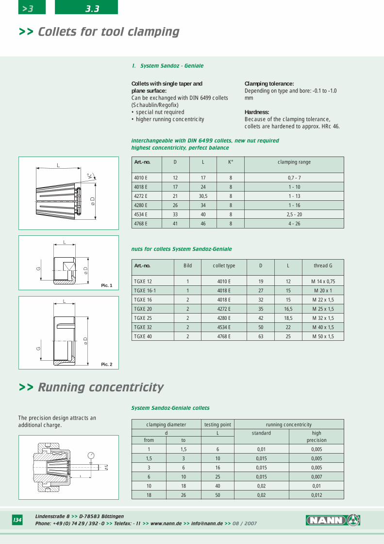
Lindenstraße 8 >> D-78583 Böttingen
Phone: +49 (0) 74 29 / 392 - 0 >> Telefax: - 11 >> www.nann.de >> [email protected] >> 08 / 2007134
>> Collets for tool clamping
interchangeable with DIN 6499 collets, new nut required
highest concentricity, perfect balance
Art.-no. D L K° clamping range
4010 E 12 17 8 0,7 - 7
4018 E 17 24 8 1 - 10
4272 E 21 30,5 8 1 - 13
4280 E 26 34 8 1 - 16
4534 E 33 40 8 2,5 - 20
4768 E 41 46 8 4 - 26
Collets with single taper andplane surface:Can be exchanged with DIN 6499 collets(Schaublin/Regofix)• special nut required• higher running concentricity
Clamping tolerance:Depending on type and bore: -0.1 to -1.0mm
Hardness:Because of the clamping tolerance, collets are hardened to approx. HRc 46.
L
ø D
K°
L
G
ø D
System Sandoz-Geniale collets
nuts for collets System Sandoz-Geniale
The precision design attracts an additional charge.
1. System Sandoz - Geniale
>> Running concentricity
L
ø d
clamping diameter testing point running concentricity
d L standard highfrom to precision
1 1,5 6 0,01 0,005
1,5 3 10 0,015 0,005
3 6 16 0,015 0,005
6 10 25 0,015 0,007
10 18 40 0,02 0,01
18 26 50 0,02 0,012
Art.-no. Bild collet type D L thread G
TGXE 12 1 4010 E 19 12 M 14 x 0,75
TGXE 16-1 1 4018 E 27 15 M 20 x 1
TGXE 16 2 4018 E 32 15 M 22 x 1,5
TGXE 20 2 4272 E 35 16,5 M 25 x 1,5
TGXE 25 2 4280 E 42 18,5 M 32 x 1,5
TGXE 32 2 4534 E 50 22 M 40 x 1,5
TGXE 40 2 4768 E 63 25 M 50 x 1,5
>3 3.3
L
ø D
G
Pic. 2
Pic. 1
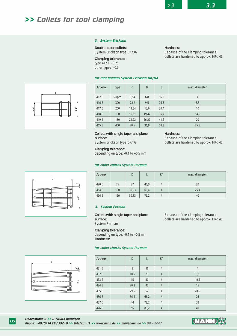
Lindenstraße 8 >> D-78583 Böttingen
Phone: +49 (0) 74 29 / 392 - 0 >> Telefax: - 11 >> www.nann.de >> [email protected] >> 08 / 2007135
>> Collets for tool clamping
for collet chucks System Perman
Art.-no. D L K° max. diameter
420 E 75 27 46,9 4 20
464 E 100 35,03 60,4 4 25,4
466 E 150 50,83 76,2 4 40
for tool holders System Erickson DK/DA
Art.-no. type d D L max. diameter
412 E Supra 5,54 6,8 16,3 4
416 E 300 7,62 9,5 25,5 6,5
417 E 200 11,34 13,6 30,4 10
418 E 100 16,51 19,47 36,7 14,5
419 E 180 22,22 26,29 41,6 20
465 E 400 30,6 36,9 50,8 25,5
Double-taper collets:System Erickson type DK/DA
Clamping tolerance:type 412 E: -0.25other types: -0.5
Collets with single taper and plane surface:System Erickson type DF/TG
Clamping tolerance:depending on type: -0.1 to –0.5 mm
Hardness:Because of the clamping tolerance, collets are hardened to approx. HRc 46.
Hardness:Because of the clamping tolerance, collets are hardened to approx. HRc 46.
for collet chucks System Perman
Art.-no. D L K° max. diameter
431 E 8 16 4 4
432 E 10,5 23 4 6,5
433 E 15 30 4 10,6
434 E 20,8 40 4 15
435 E 29,5 57 4 20,5
436 E 36,5 66,2 4 25
437 E 44 78,2 4 32
476 E 55 89,2 4 40
Collets with single taper and plane surface:System Perman
Clamping tolerance:depending on type: -0.1 to –0.5 mmHardness:
Because of the clamping tolerance, collets are hardened to approx. HRc 46.
ø D
L
ø d
L
ø D
K°
L
ø D
K°
2. System Erickson
3. System Perman
>3 3.3
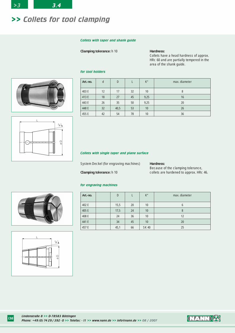
Lindenstraße 8 >> D-78583 Böttingen
Phone: +49 (0) 74 29 / 392 - 0 >> Telefax: - 11 >> www.nann.de >> [email protected] >> 08 / 2007136
for engraving machines
Art.-no. D L K° max. diameter
402 E 15,5 20 10 6
405 E 17,5 24 10 8
408 E 24 36 10 12
441 E 34 45 10 20
457 E 45,1 66 SK 40 25
>> Collets for tool clamping
for tool holders
Art.-no. d D L K° max. diameter
403 E 12 17 32 10 8
413 E 18 27 45 9,25 16
443 E 26 35 50 9,25 20
448 E 32 40,5 53 10 26
455 E 42 54 78 10 36
System Deckel (for engraving machines)
Clamping tolerance: h 10
Collets with taper and shank guide
Hardness:Because of the clamping tolerance, collets are hardened to approx. HRc 46.
L
ø D
K°
ø D
L
K°
Clamping tolerance: h 10 Hardness:Collets have a head hardness of approx.HRc 60 and are partially tempered in thearea of the shank guide.
Collets with single taper and plane surface
>3 3.4
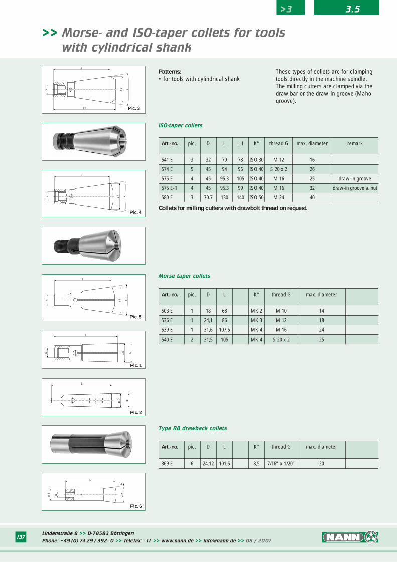
Lindenstraße 8 >> D-78583 Böttingen
Phone: +49 (0) 74 29 / 392 - 0 >> Telefax: - 11 >> www.nann.de >> [email protected] >> 08 / 2007137
>> Morse- and ISO-taper collets for tools
with cylindrical shank
Art.-no. pic. D L L 1 K° thread G max. diameter remark
541 E 3 32 70 78 ISO 30 M 12 16
574 E 5 45 94 96 ISO 40 S 20 x 2 26
575 E 4 45 95.3 105 ISO 40 M 16 25 draw-in groove
575 E-1 4 45 95.3 99 ISO 40 M 16 32 draw-in groove a. nut
580 E 3 70.7 130 140 ISO 50 M 24 40
ISO-taper collets
G
L
L1
ø D K
G ø D K
L
Pic. 3
Pic. 5
G ø D K
L
Pic. 4Collets for milling cutters with drawbolt thread on request.
Art.-no. pic. D L K° thread G max. diameter
503 E 1 18 68 MK 2 M 10 14
536 E 1 24,1 86 MK 3 M 12 18
539 E 1 31,6 107,5 MK 4 M 16 24
540 E 2 31,5 105 MK 4 S 20 x 2 25
Morse taper collets
G
L
Kø D
L
ø D K
Pic. 1
Pic. 2
K°
Gø d
L
ø D
Art.-no. pic. D L K° thread G max. diameter
369 E 6 24,12 101,5 8,5 7/16” x 1/20“ 20
Type R8 drawback collets
Pic. 6
Patterns:• for tools with cylindrical shank
These types of collets are for clampingtools directly in the machine spindle. The milling cutters are clamped via thedraw bar or the draw-in groove (Mahogroove).
>3 3.5
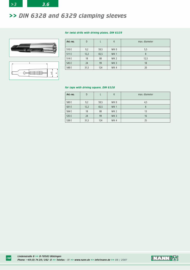
Lindenstraße 8 >> D-78583 Böttingen
Phone: +49 (0) 74 29 / 392 - 0 >> Telefax: - 11 >> www.nann.de >> [email protected] >> 08 / 2007138
L
ø D K
for twist drills with driving plates, DIN 6329
Art.-no. D L K max. diameter
510 E 9,2 59,5 MK 0 5,5
511 E 12,2 65,5 MK 1 8
514 E 18 80 MK 2 12,5
545 E 24 99 MK 3 18
548 E 31,5 124 MK 4 20
for taps with driving square, DIN 6328
Art.-no. D L K max. diameter
500 E 9,2 59,5 MK 0 4,5
501 E 12,2 65,5 MK 1 8
504 E 18 80 MK 2 13
535 E 24 99 MK 3 16
538 E 31,5 124 MK 4 25
>> DIN 6328 and 6329 clamping sleeves
>3 3.6
Lindenstraße 8 >> D-78583 Böttingen
Phone: +49 (0) 74 29 / 392 - 0 >> Telefax: - 11 >> www.nann.de >> [email protected] >> 08 / 2007138
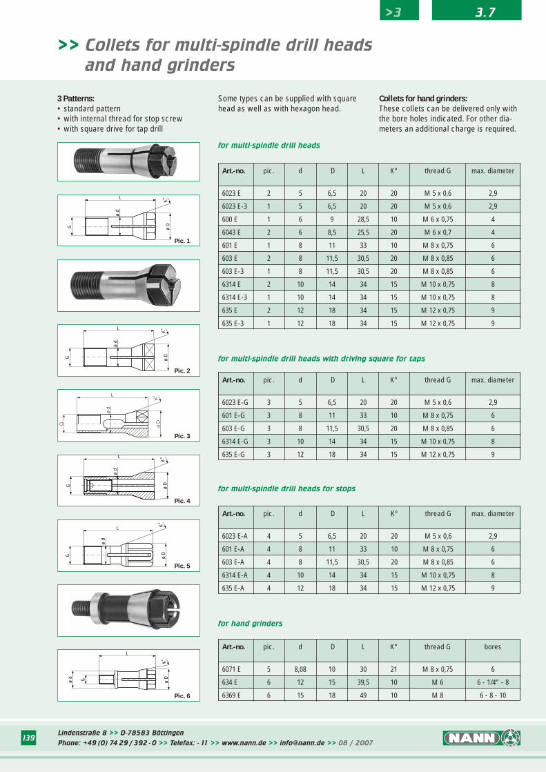
139
for multi-spindle drill heads with driving square for taps
Art.-no. pic. d D L K° thread G max. diameter
6023 E 2 5 6,5 20 20 M 5 x 0,6 2,9
6023 E-3 1 5 6,5 20 20 M 5 x 0,6 2,9
600 E 1 6 9 28,5 10 M 6 x 0,75 4
6043 E 2 6 8,5 25,5 20 M 6 x 0,7 4
601 E 1 8 11 33 10 M 8 x 0,75 6
603 E 2 8 11,5 30,5 20 M 8 x 0,85 6
603 E-3 1 8 11,5 30,5 20 M 8 x 0,85 6
6314 E 2 10 14 34 15 M 10 x 0,75 8
6314 E-3 1 10 14 34 15 M 10 x 0,75 8
635 E 2 12 18 34 15 M 12 x 0,75 9
635 E-3 1 12 18 34 15 M 12 x 0,75 9
Art.-no. pic. d D L K° thread G max. diameter
6023 E-G 3 5 6,5 20 20 M 5 x 0,6 2,9
601 E-G 3 8 11 33 10 M 8 x 0,75 6
603 E-G 3 8 11,5 30,5 20 M 8 x 0,85 6
6314 E-G 3 10 14 34 15 M 10 x 0,75 8
635 E-G 3 12 18 34 15 M 12 x 0,75 9
for multi-spindle drill heads
L
G
ø d
ø D
K°
L
G
ø d
ø D
K°
>> Collets for multi-spindle drill heads
and hand grinders
Pic. 2
G ø D
K°
ø d
L
Pic. 3
3 Patterns:• standard pattern• with internal thread for stop screw• with square drive for tap drill
Some types can be supplied with squarehead as well as with hexagon head.
Collets for hand grinders:These collets can be delivered only withthe bore holes indicated. For other dia-meters an additional charge is required.
for multi-spindle drill heads for stops
Art.-no. pic. d D L K° thread G max. diameter
6023 E-A 4 5 6,5 20 20 M 5 x 0,6 2,9
601 E-A 4 8 11 33 10 M 8 x 0,75 6
603 E-A 4 8 11,5 30,5 20 M 8 x 0,85 6
6314 E-A 4 10 14 34 15 M 10 x 0,75 8
635 E-A 4 12 18 34 15 M 12 x 0,75 9
Art.-no. pic. d D L K° thread G bores
6071 E 5 8,08 10 30 21 M 8 x 0,75 6
634 E 6 12 15 39,5 10 M 6 6 - 1/4“ - 8
6369 E 6 15 18 49 10 M 8 6 - 8 - 10
for hand grinders
G
L
ø D
K°
ø d
Pic. 5
K°
ø D
ø d G
L
Pic. 6
G
ø d
L
ø D
K°
Pic. 4
>3 3.7
Pic. 1
Lindenstraße 8 >> D-78583 Böttingen
Phone: +49 (0) 74 29 / 392 - 0 >> Telefax: - 11 >> www.nann.de >> [email protected] >> 08 / 2007139
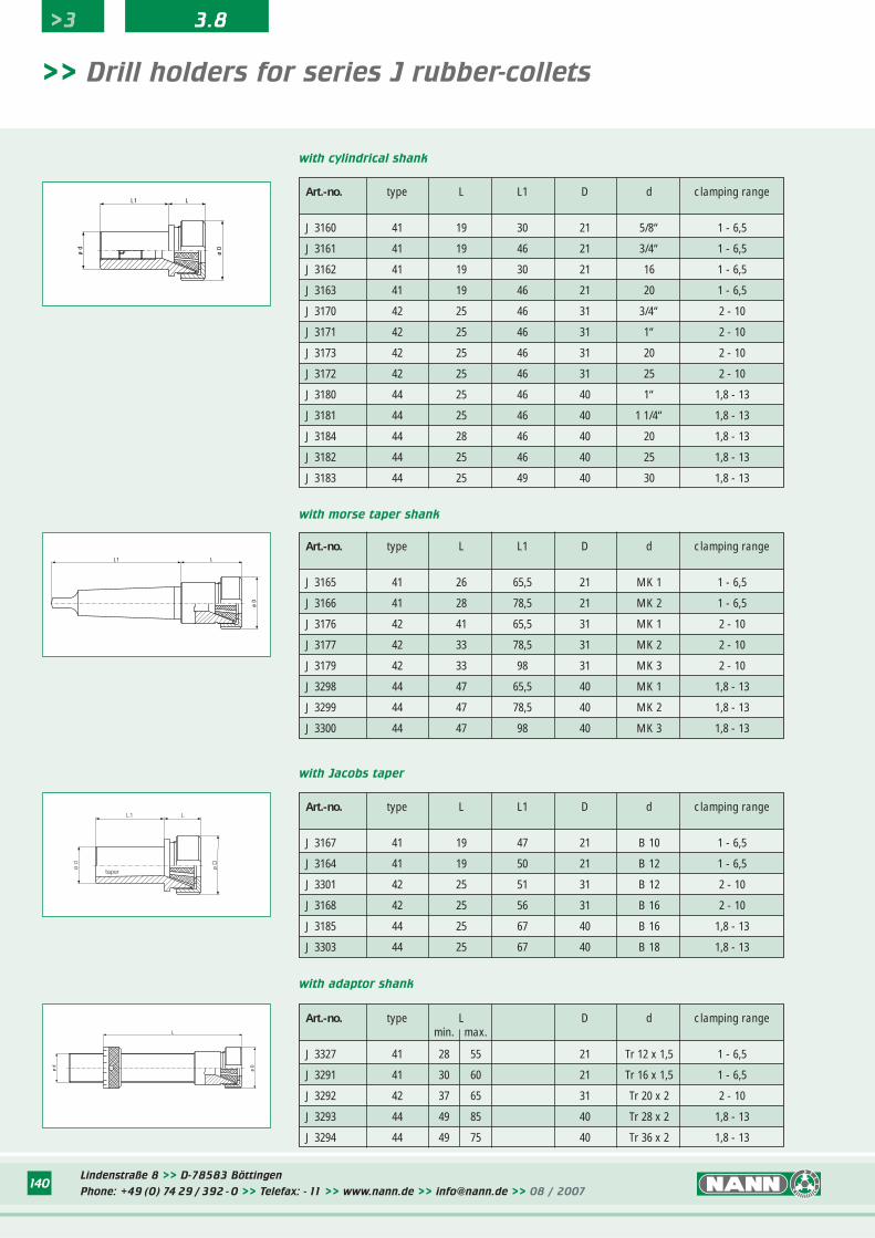
Lindenstraße 8 >> D-78583 Böttingen
Phone: +49 (0) 74 29 / 392 - 0 >> Telefax: - 11 >> www.nann.de >> [email protected] >> 08 / 2007140
>> Drill holders for series J rubber-collets
Art.-no. type L L1 D d clamping range
J 3160 41 19 30 21 5/8“ 1 - 6,5
J 3161 41 19 46 21 3/4“ 1 - 6,5
J 3162 41 19 30 21 16 1 - 6,5
J 3163 41 19 46 21 20 1 - 6,5
J 3170 42 25 46 31 3/4“ 2 - 10
J 3171 42 25 46 31 1“ 2 - 10
J 3173 42 25 46 31 20 2 - 10
J 3172 42 25 46 31 25 2 - 10
J 3180 44 25 46 40 1“ 1,8 - 13
J 3181 44 25 46 40 1 1/4“ 1,8 - 13
J 3184 44 28 46 40 20 1,8 - 13
J 3182 44 25 46 40 25 1,8 - 13
J 3183 44 25 49 40 30 1,8 - 13
with cylindrical shank
Art.-no. type L L1 D d clamping range
J 3165 41 26 65,5 21 MK 1 1 - 6,5
J 3166 41 28 78,5 21 MK 2 1 - 6,5
J 3176 42 41 65,5 31 MK 1 2 - 10
J 3177 42 33 78,5 31 MK 2 2 - 10
J 3179 42 33 98 31 MK 3 2 - 10
J 3298 44 47 65,5 40 MK 1 1,8 - 13
J 3299 44 47 78,5 40 MK 2 1,8 - 13
J 3300 44 47 98 40 MK 3 1,8 - 13
with morse taper shank
Art.-no. type L L1 D d clamping range
J 3167 41 19 47 21 B 10 1 - 6,5
J 3164 41 19 50 21 B 12 1 - 6,5
J 3301 42 25 51 31 B 12 2 - 10
J 3168 42 25 56 31 B 16 2 - 10
J 3185 44 25 67 40 B 16 1,8 - 13
J 3303 44 25 67 40 B 18 1,8 - 13
with Jacobs taper
Art.-no. type L D d clamping rangemin. max.
J 3327 41 28 55 21 Tr 12 x 1,5 1 - 6,5
J 3291 41 30 60 21 Tr 16 x 1,5 1 - 6,5
J 3292 42 37 65 31 Tr 20 x 2 2 - 10
J 3293 44 49 85 40 Tr 28 x 2 1,8 - 13
J 3294 44 49 75 40 Tr 36 x 2 1,8 - 13
with adaptor shank
ø d
ø D
L
L
ø D
L1
ø d
taper
L
ø D
L1
ø D
LL1
ø d
>3 3.8
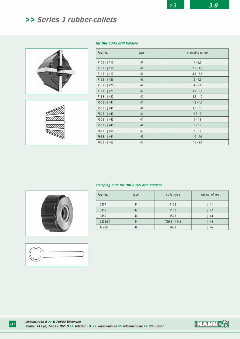
Lindenstraße 8 >> D-78583 Böttingen
Phone: +49 (0) 74 29 / 392 - 0 >> Telefax: - 11 >> www.nann.de >> [email protected] >> 08 / 2007141
>> Series J rubber-collets
Art.-no. type clamping range
710 E - J115 41 1 - 2,5
710 E - J116 41 2,5 - 4,5
710 E - J117 41 4,5 - 6,5
715 E - J423 42 2 - 4,5
715 E - J420 42 4,5 - 8
715 E - J421 42 3,5 - 6,5
715 E - J422 42 6,5 - 10
750 E - J444 44 1,8 - 4,5
750 E - J441 44 4,5 - 10
750 E - J443 44 2,8 - 7
750 E - J440 44 7 - 13
750 E - J445 44 9 - 15
766 E - J460 46 6 - 10
766 E - J461 46 10 - 16
766 E - J462 46 16 - 23
for DIN 6345 drill holders
Art.-no. type collet type Art-no. of key
J 3157 41 710 E J 41
J 3158 42 715 E J 42
J 3159 44 750 E J 44
J 3159/S1 44 750 E - J445 J 44
J N 460 46 766 E J 46
clamping nuts for DIN 6345 drill holders
>3 3.8
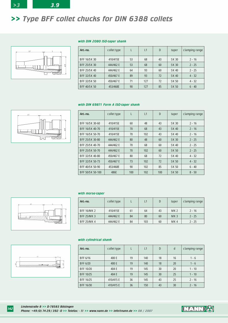
Lindenstraße 8 >> D-78583 Böttingen
Phone: +49 (0) 74 29 / 392 - 0 >> Telefax: - 11 >> www.nann.de >> [email protected] >> 08 / 2007142
with DIN 2080 ISO-taper shank
>> Type BFF collet chucks for DIN 6388 collets
Art.-no. collet type L L1 D taper clamping range
BFF 16/SK 30-60 410/415E 60 48 43 SK 30 2 - 16
BFF 16/SK 40-70 410/415E 70 68 43 SK 40 2 - 16
BFF 16/SK 50-70 410/415E 70 102 43 SK 40 2 - 16
BFF 25/SK 30-80 444/462 E 80 48 60 SK 30 2 - 25
BFF 25/SK 40-70 444/462 E 70 68 60 SK 40 2 - 25
BFF 25/SK 50-70 444/462 E 70 102 60 SK 50 2 - 25
BFF 32/SK 40-80 450/467 E 80 68 72 SK 40 4 - 32
BFF 32/SK 50-73 450/467 E 73 102 72 SK 50 4 - 32
BFF 40/SK 50-90 453/468E 90 102 85 SK 50 6 - 40
BFF 50/SK 50-100 486E 100 102 100 SK 50 8 - 50
with DIN 69871 Form A ISO-taper shank
Art.-no. collet type L L1 D taper clamping range
BFF 16/MK 2 410/415E 61 64 43 MK 2 2 - 16
BFF 25/MK 3 444/462 E 84 80 60 MK 3 2 - 25
BFF 25/MK 4 444/462 E 84 103 60 MK 4 2 - 25
with morse-taper
Art.-no. collet type L L1 D d clamping range
BFF 6/16 400 E 19 140 18 16 1 - 6
BFF 6/20 400 E 19 140 18 20 1 - 6
BFF 10/20 404 E 19 145 30 20 1 - 10
BFF 10/25 404 E 19 145 30 25 1 - 10
BFF 16/25 410/415 E 36 145 43 25 2 - 16
BFF 16/30 410/415 E 36 150 43 30 2 - 16
with cylindrical shank
ø D
L1 L
LL1
ø D
LL1
ø D
ø D
ø d
L1 L
Art.-no. collet type L L1 D taper clamping range
BFF 16/SK 30 410/415E 53 68 43 SK 30 2 - 16
BFF 25/SK 30 444/462 E 53 68 60 SK 30 2 - 25
BFF 25/SK 40 444/462 E 64 93 60 SK 40 2 - 25
BFF 32/SK 40 450/467 E 89 93 72 SK 40 4 - 32
BFF 32/SK 50 450/467 E 71 127 72 SK 50 4 - 32
BFF 40/SK 50 453/468E 90 127 85 SK 50 6 - 40
>3 3.9
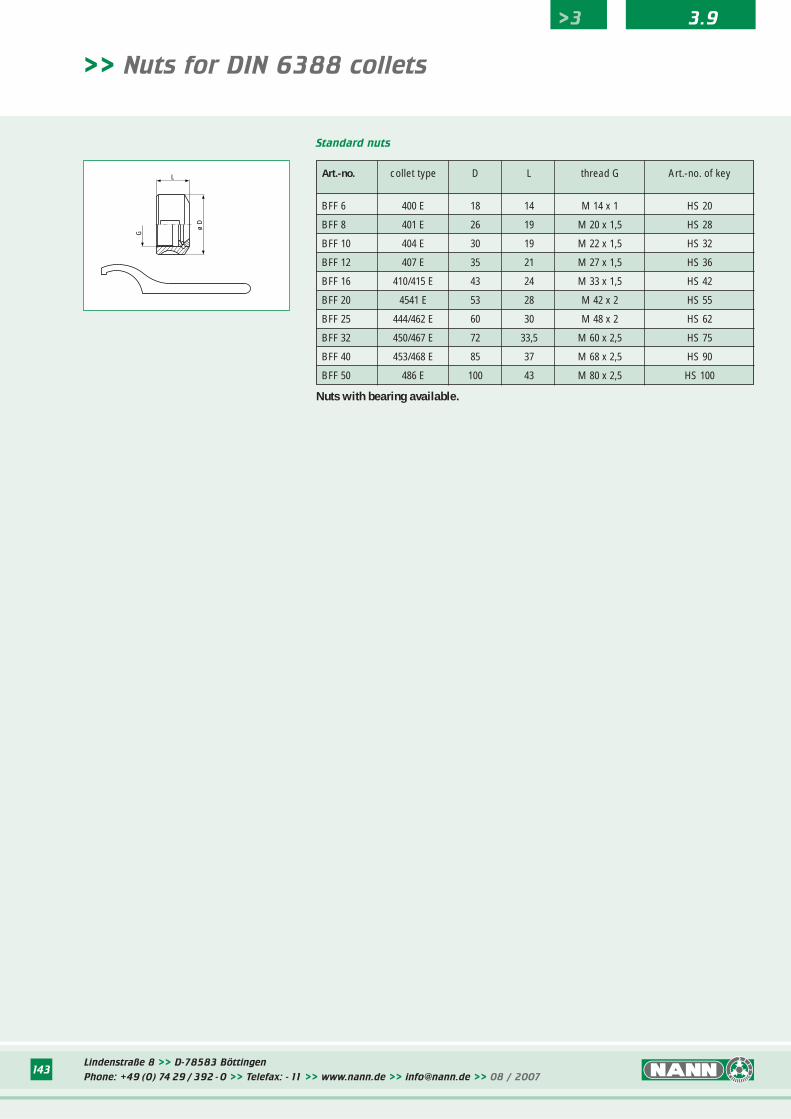
Lindenstraße 8 >> D-78583 Böttingen
Phone: +49 (0) 74 29 / 392 - 0 >> Telefax: - 11 >> www.nann.de >> [email protected] >> 08 / 2007143
>> Nuts for DIN 6388 collets
Art.-no. collet type D L thread G Art.-no. of key
BFF 6 400 E 18 14 M 14 x 1 HS 20
BFF 8 401 E 26 19 M 20 x 1,5 HS 28
BFF 10 404 E 30 19 M 22 x 1,5 HS 32
BFF 12 407 E 35 21 M 27 x 1,5 HS 36
BFF 16 410/415 E 43 24 M 33 x 1,5 HS 42
BFF 20 4541 E 53 28 M 42 x 2 HS 55
BFF 25 444/462 E 60 30 M 48 x 2 HS 62
BFF 32 450/467 E 72 33,5 M 60 x 2,5 HS 75
BFF 40 453/468 E 85 37 M 68 x 2,5 HS 90
BFF 50 486 E 100 43 M 80 x 2,5 HS 100
Standard nuts
Nuts with bearing available.
>3 3.9
G
ø D
L
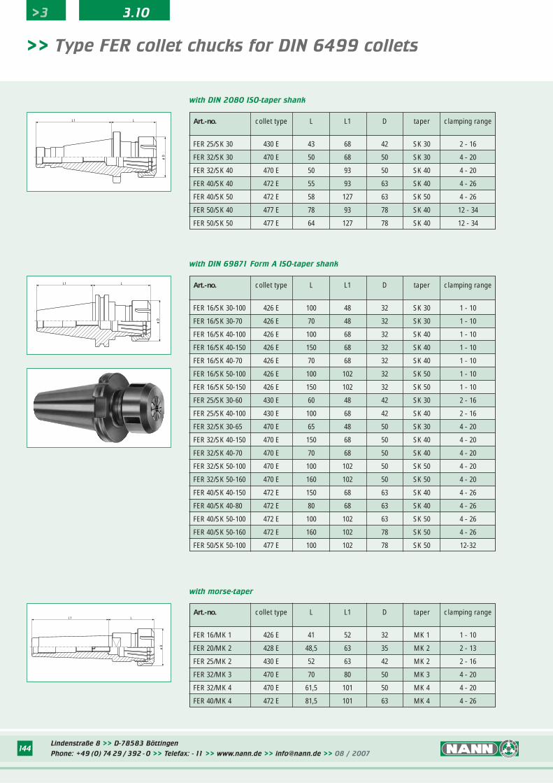
Lindenstraße 8 >> D-78583 Böttingen
Phone: +49 (0) 74 29 / 392 - 0 >> Telefax: - 11 >> www.nann.de >> [email protected] >> 08 / 2007144
>> Type FER collet chucks for DIN 6499 collets
with DIN 69871 Form A ISO-taper shank
ø D
LL1
with DIN 2080 ISO-taper shank
L
ø D
L1
with morse-taper
L
ø D
L1
Art.-no. collet type L L1 D taper clamping range
FER 25/SK 30 430 E 43 68 42 SK 30 2 - 16
FER 32/SK 30 470 E 50 68 50 SK 30 4 - 20
FER 32/SK 40 470 E 50 93 50 SK 40 4 - 20
FER 40/SK 40 472 E 55 93 63 SK 40 4 - 26
FER 40/SK 50 472 E 58 127 63 SK 50 4 - 26
FER 50/SK 40 477 E 78 93 78 SK 40 12 - 34
FER 50/SK 50 477 E 64 127 78 SK 40 12 - 34
Art.-no. collet type L L1 D taper clamping range
FER 16/SK 30-100 426 E 100 48 32 SK 30 1 - 10
FER 16/SK 30-70 426 E 70 48 32 SK 30 1 - 10
FER 16/SK 40-100 426 E 100 68 32 SK 40 1 - 10
FER 16/SK 40-150 426 E 150 68 32 SK 40 1 - 10
FER 16/SK 40-70 426 E 70 68 32 SK 40 1 - 10
FER 16/SK 50-100 426 E 100 102 32 SK 50 1 - 10
FER 16/SK 50-150 426 E 150 102 32 SK 50 1 - 10
FER 25/SK 30-60 430 E 60 48 42 SK 30 2 - 16
FER 25/SK 40-100 430 E 100 68 42 SK 40 2 - 16
FER 32/SK 30-65 470 E 65 48 50 SK 30 4 - 20
FER 32/SK 40-150 470 E 150 68 50 SK 40 4 - 20
FER 32/SK 40-70 470 E 70 68 50 SK 40 4 - 20
FER 32/SK 50-100 470 E 100 102 50 SK 50 4 - 20
FER 32/SK 50-160 470 E 160 102 50 SK 50 4 - 20
FER 40/SK 40-150 472 E 150 68 63 SK 40 4 - 26
FER 40/SK 40-80 472 E 80 68 63 SK 40 4 - 26
FER 40/SK 50-100 472 E 100 102 63 SK 50 4 - 26
FER 40/SK 50-160 472 E 160 102 78 SK 50 4 - 26
FER 50/SK 50-100 477 E 100 102 78 SK 50 12-32
Art.-no. collet type L L1 D taper clamping range
FER 16/MK 1 426 E 41 52 32 MK 1 1 - 10
FER 20/MK 2 428 E 48,5 63 35 MK 2 2 - 13
FER 25/MK 2 430 E 52 63 42 MK 2 2 - 16
FER 32/MK 3 470 E 70 80 50 MK 3 4 - 20
FER 32/MK 4 470 E 61,5 101 50 MK 4 4 - 20
FER 40/MK 4 472 E 81,5 101 63 MK 4 4 - 26
>3 3.10
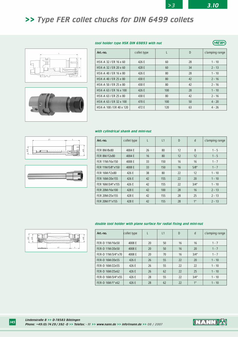
Lindenstraße 8 >> D-78583 Böttingen
Phone: +49 (0) 74 29 / 392 - 0 >> Telefax: - 11 >> www.nann.de >> [email protected] >> 08 / 2007145
>> Type FER collet chucks for DIN 6499 collets
with cylindrical shank and mini-nut
ø d
ø D
LL1
double tool holder with plane surface for radial fixing and mini-nut
ø D
ø D
ø d
L1L L
tool holder type HSK DIN 69893 with nut
L
D
Art.-no. collet type L D clamping range
HSK-A 32 / ER 16 x 60 426 E 60 28 1 - 10
HSK-A 32 / ER 20 x 60 428 E 60 34 2 - 13
HSK-A 40 / ER 16 x 80 426 E 80 28 1 - 10
HSK-A 40 / ER 25 x 80 430 E 80 42 2 - 16
HSK-A 50 / ER 25 x 80 430 E 80 42 2 - 16
HSK-A 63 / ER 16 x 100 426 E 100 28 1 - 10
HSK-A 63 / ER 25 x 80 430 E 80 42 2 - 16
HSK-A 63 / ER 32 x 100 470 E 100 50 4 - 20
HSK-A 100 / ER 40 x 120 472 E 120 63 4 - 26
Art.-no. collet type L L1 D d clamping range
FER 8M/8x80 4004 E 26 80 12 8 1 - 5
FER 8M/12x80 4004 E 16 80 12 12 1 - 5
FER 11M/16x150 4008 E 33 150 16 16 1 - 7
FER 11M/5/8“x150 4008 E 33 150 16 5/8“ 1 - 7
FER 16M/12x80 426 E 38 80 22 12 1 - 10
FER 16M/20x155 426 E 42 155 22 20 1 - 10
FER 16M/3/4“x155 426 E 42 155 22 3/4“ 1 - 10
FER 20M/16x100 428 E 42 100 28 16 2 - 13
FER 20M/25x155 428 E 42 155 28 25 2 - 13
FER 20M/1“x155 428 E 42 155 28 1“ 2 - 13
Art.-no. collet type L L1 D d clamping range
FER-D 11M/16x50 4008 E 20 50 16 16 1 - 7
FER-D 11M/20x50 4008 E 20 50 16 20 1 - 7
FER-D 11M/3/4“x70 4008 E 20 70 16 3/4“ 1 - 7
FER-D 16M/20x55 426 E 26 55 22 20 1 - 10
FER-D 16M/22x55 426 E 26 55 22 22 1 - 10
FER-D 16M/25x62 426 E 26 62 22 25 1 - 10
FER-D 16M/3/4“x55 426 E 28 55 22 3/4“ 1 - 10
FER-D 16M/1“x62 426 E 28 62 22 1“ 1 - 10
>3 3.10
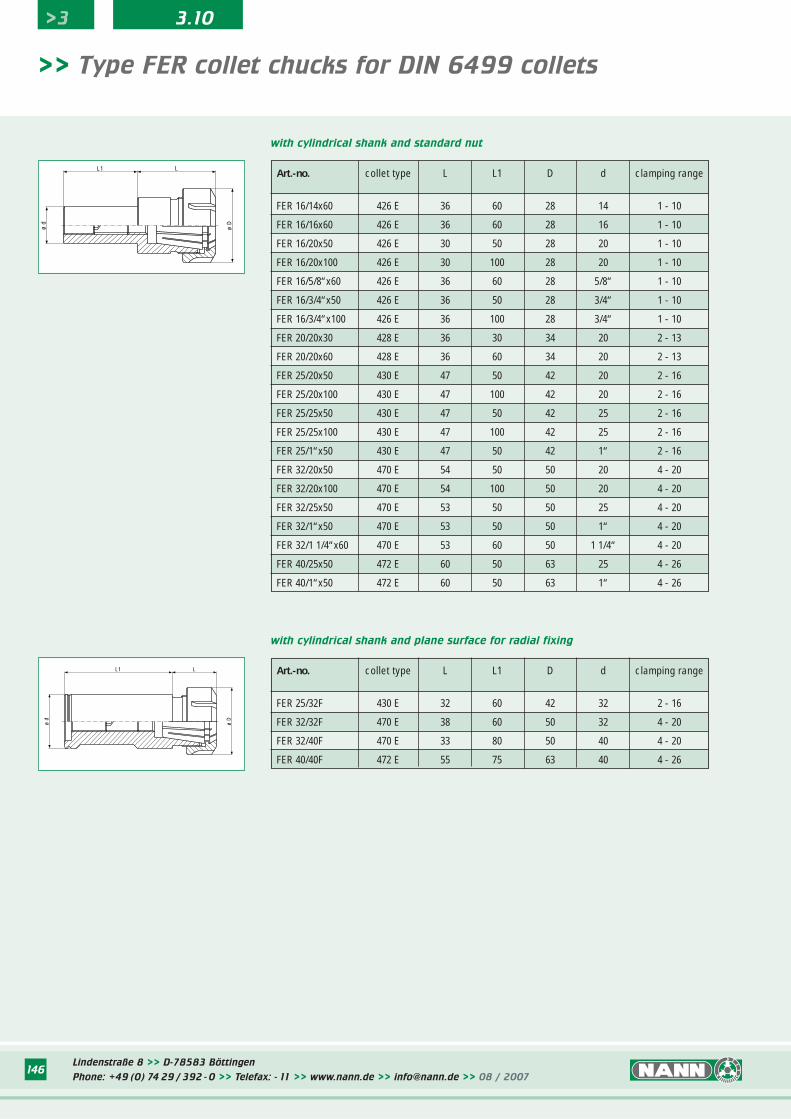
Lindenstraße 8 >> D-78583 Böttingen
Phone: +49 (0) 74 29 / 392 - 0 >> Telefax: - 11 >> www.nann.de >> [email protected] >> 08 / 2007146
>> Type FER collet chucks for DIN 6499 collets
with cylindrical shank and plane surface for radial fixing
ø d
ø D
LL1
with cylindrical shank and standard nut
ø D
ø d
LL1 Art.-no. collet type L L1 D d clamping range
FER 16/14x60 426 E 36 60 28 14 1 - 10
FER 16/16x60 426 E 36 60 28 16 1 - 10
FER 16/20x50 426 E 30 50 28 20 1 - 10
FER 16/20x100 426 E 30 100 28 20 1 - 10
FER 16/5/8“x60 426 E 36 60 28 5/8“ 1 - 10
FER 16/3/4“x50 426 E 36 50 28 3/4“ 1 - 10
FER 16/3/4“x100 426 E 36 100 28 3/4“ 1 - 10
FER 20/20x30 428 E 36 30 34 20 2 - 13
FER 20/20x60 428 E 36 60 34 20 2 - 13
FER 25/20x50 430 E 47 50 42 20 2 - 16
FER 25/20x100 430 E 47 100 42 20 2 - 16
FER 25/25x50 430 E 47 50 42 25 2 - 16
FER 25/25x100 430 E 47 100 42 25 2 - 16
FER 25/1“x50 430 E 47 50 42 1“ 2 - 16
FER 32/20x50 470 E 54 50 50 20 4 - 20
FER 32/20x100 470 E 54 100 50 20 4 - 20
FER 32/25x50 470 E 53 50 50 25 4 - 20
FER 32/1“x50 470 E 53 50 50 1“ 4 - 20
FER 32/1 1/4“x60 470 E 53 60 50 1 1/4“ 4 - 20
FER 40/25x50 472 E 60 50 63 25 4 - 26
FER 40/1“x50 472 E 60 50 63 1“ 4 - 26
Art.-no. collet type L L1 D d clamping range
FER 25/32F 430 E 32 60 42 32 2 - 16
FER 32/32F 470 E 38 60 50 32 4 - 20
FER 32/40F 470 E 33 80 50 40 4 - 20
FER 40/40F 472 E 55 75 63 40 4 - 26
>3 3.10
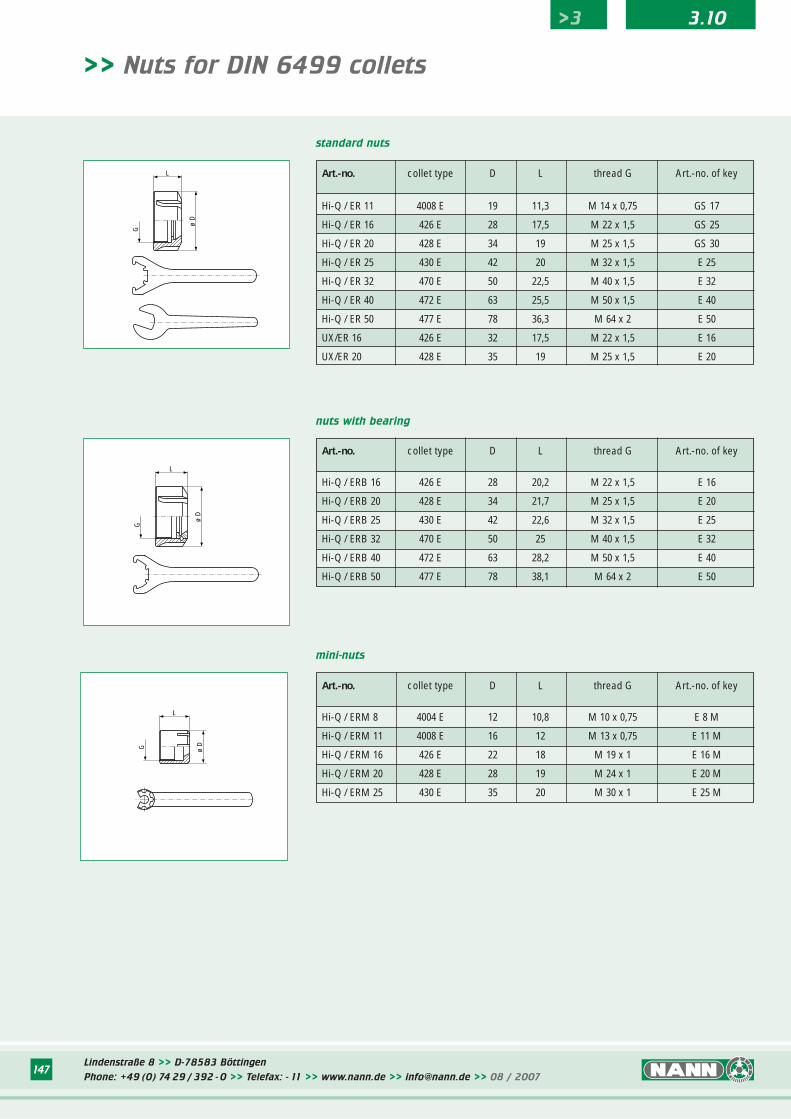
Lindenstraße 8 >> D-78583 Böttingen
Phone: +49 (0) 74 29 / 392 - 0 >> Telefax: - 11 >> www.nann.de >> [email protected] >> 08 / 2007147
>> Nuts for DIN 6499 collets
standard nuts
nuts with bearing
mini-nuts
Art.-no. collet type D L thread G Art.-no. of key
Hi-Q / ER 11 4008 E 19 11,3 M 14 x 0,75 GS 17
Hi-Q / ER 16 426 E 28 17,5 M 22 x 1,5 GS 25
Hi-Q / ER 20 428 E 34 19 M 25 x 1,5 GS 30
Hi-Q / ER 25 430 E 42 20 M 32 x 1,5 E 25
Hi-Q / ER 32 470 E 50 22,5 M 40 x 1,5 E 32
Hi-Q / ER 40 472 E 63 25,5 M 50 x 1,5 E 40
Hi-Q / ER 50 477 E 78 36,3 M 64 x 2 E 50
UX/ER 16 426 E 32 17,5 M 22 x 1,5 E 16
UX/ER 20 428 E 35 19 M 25 x 1,5 E 20
Art.-no. collet type D L thread G Art.-no. of key
Hi-Q / ERB 16 426 E 28 20,2 M 22 x 1,5 E 16
Hi-Q / ERB 20 428 E 34 21,7 M 25 x 1,5 E 20
Hi-Q / ERB 25 430 E 42 22,6 M 32 x 1,5 E 25
Hi-Q / ERB 32 470 E 50 25 M 40 x 1,5 E 32
Hi-Q / ERB 40 472 E 63 28,2 M 50 x 1,5 E 40
Hi-Q / ERB 50 477 E 78 38,1 M 64 x 2 E 50
Art.-no. collet type D L thread G Art.-no. of key
Hi-Q / ERM 8 4004 E 12 10,8 M 10 x 0,75 E 8 M
Hi-Q / ERM 11 4008 E 16 12 M 13 x 0,75 E 11 M
Hi-Q / ERM 16 426 E 22 18 M 19 x 1 E 16 M
Hi-Q / ERM 20 428 E 28 19 M 24 x 1 E 20 M
Hi-Q / ERM 25 430 E 35 20 M 30 x 1 E 25 M
>3 3.10
G
ø D
L
G
L
ø D
G ø D
L
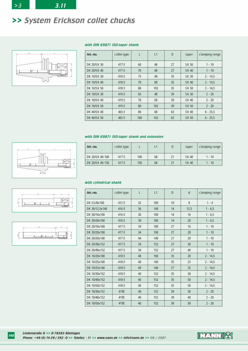
Lindenstraße 8 >> D-78583 Böttingen
Phone: +49 (0) 74 29 / 392 - 0 >> Telefax: - 11 >> www.nann.de >> [email protected] >> 08 / 2007148
>> System Erickson collet chucks
Art.-no. collet type L L1 D taper clamping range
DK 20/SK 30 417 E 60 48 27 SK 30 1 - 10
DK 20/SK 40 417 E 70 68 27 SK 40 1 - 10
DK 10/SK 30 418 E 75 48 35 SK 30 2 - 14,5
DK 10/SK 40 418 E 70 68 35 SK 40 2 - 14,5
DK 10/SK 50 418 E 80 102 35 SK 50 2 - 14,5
DK 18/SK 30 419 E 65 48 39 SK 30 2 - 20
DK 18/SK 40 419 E 70 68 39 SK 40 2 - 20
DK 18/SK 50 419 E 80 102 39 SK 50 2 - 20
DK 40/SK 40 465 E 80 68 63 SK 40 6 - 25,5
DK 40/SK 50 465 E 100 102 63 SK 50 6 - 25,5
with DIN 69871 ISO-taper shank
Art.-no. collet type L L1 D taper clamping range
DK 20/SK 40-100 417 E 100 68 21 SK 40 1 - 10
DK 20/SK 40-150 417 E 150 68 21 SK 40 1 - 10
with DIN 69871 ISO-taper shank and extension
with cylindrical shank
L1
ø D
L
ø D
LL1
ø d
ø D
LL1
ø D
LL1
ø d
Art.-no. collet type L L1 D d clamping range
DK SU/8x100 412 E 32 100 10 8 1 - 4
DK 30/12,5x140 416 E 36 140 14 12,5 1 - 6,5
DK 30/16x100 416 E 30 100 14 16 1 - 6,5
DK 30/20x100 416 E 30 100 14 20 1 - 6,5
DK 20/16x100 417 E 34 100 27 16 1 - 10
DK 20/20x100 417 E 34 100 27 20 1 - 10
DK 20/20x140 417 E 44 140 21 20 1 - 10
DK 20/30x152 417 E 34 152 27 30 1 - 10
DK 20/40x152 417 E 34 152 27 40 1 - 10
DK 10/20x100 418 E 48 100 35 20 2 - 14,5
DK 10/25x100 418 E 40 100 35 25 2 - 14,5
DK 10/25x140 418 E 49 140 27 25 2 - 14,5
DK 10/30x152 418 E 40 152 35 30 2 - 14,5
DK 10/40x152 418 E 40 152 35 50 2 - 14,5
DK 10/50x152 418 E 40 152 35 50 2 - 14,5
DK 18/30x152 419E 40 152 39 30 2 - 20
DK 18/40x152 419E 40 152 39 40 2 - 20
DK 18/50x152 419E 40 152 39 50 2 - 20
>3 3.11
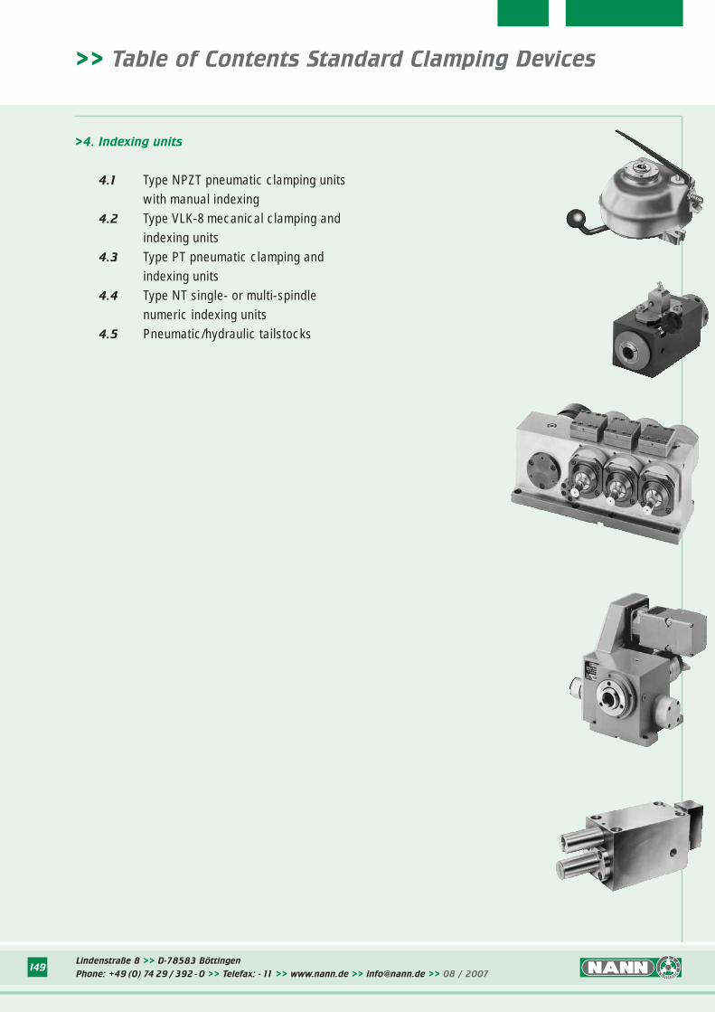
Lindenstraße 8 >> D-78583 Böttingen
Phone: +49 (0) 74 29 / 392 - 0 >> Telefax: - 11 >> www.nann.de >> [email protected] >> 08 / 2007149
>4. Indexing units
4.1 Type NPZT pneumatic clamping units with manual indexing
4.2 Type VLK-8 mecanical clamping and indexing units
4.3 Type PT pneumatic clamping and indexing units
4.4 Type NT single- or multi-spindle numeric indexing units
4.5 Pneumatic/hydraulic tailstocks
>> Table of Contents Standard Clamping Devices
Lindenstraße 8 >> D-78583 Böttingen
Phone: +49 (0) 74 29 / 392 - 0 >> Telefax: - 11 >> www.nann.de >> [email protected] >> 08 / 2007149
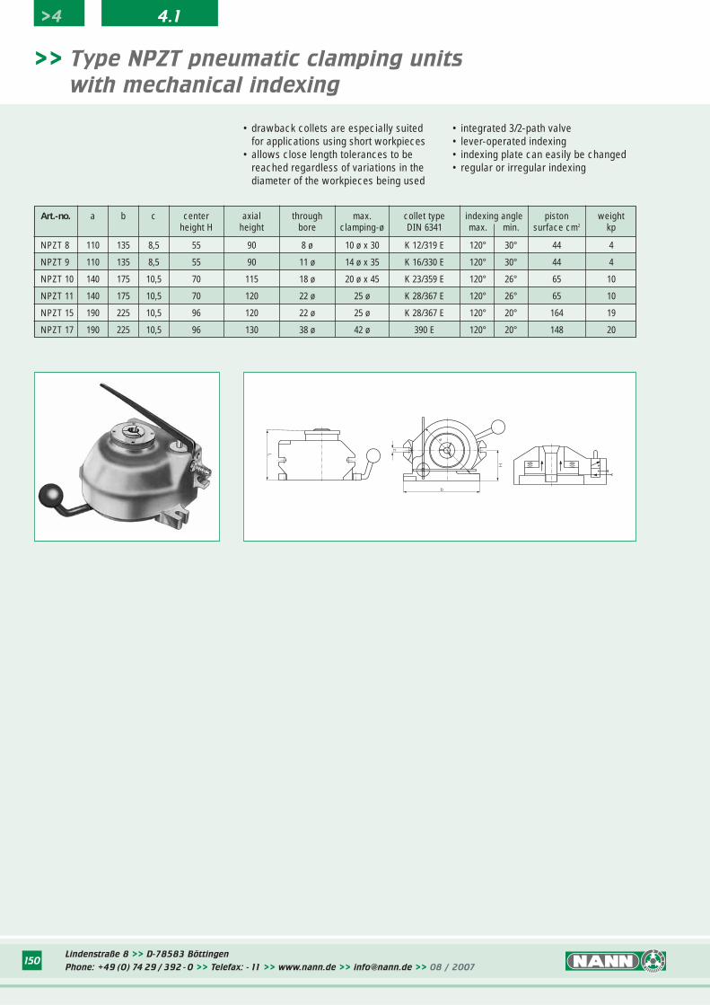
Lindenstraße 8 >> D-78583 Böttingen
Phone: +49 (0) 74 29 / 392 - 0 >> Telefax: - 11 >> www.nann.de >> [email protected] >> 08 / 2007150
• drawback collets are especially suitedfor applications using short workpieces
• allows close length tolerances to be reached regardless of variations in the diameter of the workpieces being used
>> Type NPZT pneumatic clamping units
with mechanical indexing
• integrated 3/2-path valve• lever-operated indexing• indexing plate can easily be changed• regular or irregular indexing
Art.-no. a b c center axial through max. collet type indexing angle piston weightheight H height bore clamping-ø DIN 6341 max. min. surface cm2 kp
NPZT 8 110 135 8,5 55 90 8 ø 10 ø x 30 K 12/319 E 120° 30° 44 4
NPZT 9 110 135 8,5 55 90 11 ø 14 ø x 35 K 16/330 E 120° 30° 44 4
NPZT 10 140 175 10,5 70 115 18 ø 20 ø x 45 K 23/359 E 120° 26° 65 10
NPZT 11 140 175 10,5 70 120 22 ø 25 ø K 28/367 E 120° 26° 65 10
NPZT 15 190 225 10,5 96 120 22 ø 25 ø K 28/367 E 120° 20° 164 19
NPZT 17 190 225 10,5 96 130 38 ø 42 ø 390 E 120° 20° 148 20
>4 4.1
L
b
H
c
a
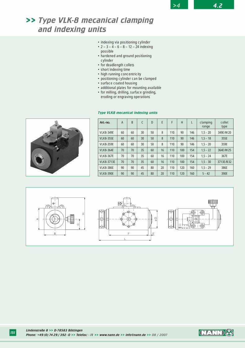
Lindenstraße 8 >> D-78583 Böttingen
Phone: +49 (0) 74 29 / 392 - 0 >> Telefax: - 11 >> www.nann.de >> [email protected] >> 08 / 2007151
• indexing via positioning cylinder• 2 – 3 – 4 – 6 – 8 – 12 – 24 indexing
possible• hardened and ground positioning
cylinder• for deadlength collets• short indexing time• high running concentricity• positioning cylinder can be clamped• surface coated housing• additional plates for mounting available• for milling, drilling, surface grinding,
eroding or engraving operations
>> Type VLK-8 mecanical clamping
and indexing units
Type VLK8 mecanical indexing units
Art.-no. A B C D E F H L clamping colletrange type
VLK8-349E 60 60 30 50 8 110 90 146 1,5 - 20 349E/W20
VLK8-355E 60 60 30 50 8 110 90 146 1,5 - 18 355E
VLK8-359E 60 60 30 50 8 110 90 146 1,5 - 20 359E
VLK8-364E 70 70 35 60 16 110 100 154 1,5 - 22 364E/W25
VLK8-367E 70 70 35 60 16 110 100 154 1,5 - 24 367E
VLK8-3713E 70 70 35 60 16 110 100 154 1,5 - 30 3713E/B32
VLK8-386E 90 90 45 80 20 110 120 160 1,5 - 29 386E
VLK8-390E 90 90 45 80 20 110 120 160 5 - 42 390E
>4 4.2
B
A
C
H
2412 8 6 4 3 2
ø D
L
F E
2412 8 6 4 3 2
2412 8 6 4 3 2
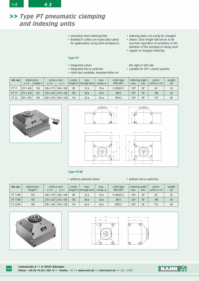
Lindenstraße 8 >> D-78583 Böttingen
Phone: +49 (0) 74 29 / 392 - 0 >> Telefax: - 11 >> www.nann.de >> [email protected] >> 08 / 2007152
• extremely short indexing time• drawback collets are especially suited
for applications using short workpieces
>> Type PT pneumatic clamping
and indexing units
• indexing plate can easily be changed• allows close length tolerances to be
reached regardless of variations in the diameter of the workpieces being used
• regular or irregular indexing
Art.-no. dimensions surface area center max. max. collet type indexing angle piston weighte x d height F a x b a x c height H through bore clamp.-ø DIN 6341 max. min. surface cm2 kp
PT 11 227 x 245 150 160 x 175 160 x 100 80 22 ø 25 ø K 28/367 E 120° 26° 65 26
PT 17 277 x 310 165 210 x 225 210 x 105 105 38 ø 42 ø 390 E 120° 18° 148 44
PT 22 297 x 335 190 230 x 245 230 x 128 116 62 ø 62 ø 3955 E 120° 18° 170 60
• integrated valves• integrated micro-switches• valve box available, mounted either on
Type PT
the right or left side• suitable for SPC control systems
Art.-no. dimensions surface area center max. max. collet type indexing angle piston weightheight F a x b a x c height H through bore clamp.-ø DIN 6341 max. min. surface cm2 kp
PT 11/W 150 160 x 175 160 x 100 80 22 ø 25 ø K 28/367 E 120° 26° 65 26
PT 17/W 165 210 x 225 210 x 105 105 38 ø 42 ø 390 E 120° 18° 148 44
PT 22/W 190 230 x 245 230 x 128 116 62 ø 62 ø 3955 E 120° 18° 170 60
• without solenoid valves
Type PT/W
• without micro-switches
F
c
F
c
c
b
ee
b
H
d d
a a
B
H
a
F
c
>4 4.3
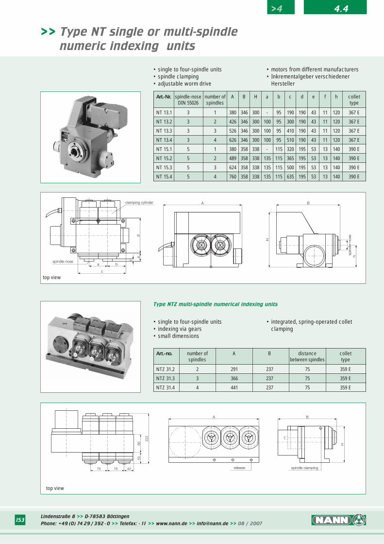
Lindenstraße 8 >> D-78583 Böttingen
Phone: +49 (0) 74 29 / 392 - 0 >> Telefax: - 11 >> www.nann.de >> [email protected] >> 08 / 2007153
>> Type NT single or multi-spindle
numeric indexing units
• single to four-spindle units• spindle clamping• adjustable worm drive
• motors from different manufacturers• Inkrementalgeber verschiedener
Hersteller
Art.-Nr. spindle-nose number of A B H a b c d e f h colletDIN 55026 spindles type
NT 13.1 3 1 380 346 300 - 95 190 190 43 11 120 367 E
NT 13.2 3 2 426 346 300 100 95 300 190 43 11 120 367 E
NT 13.3 3 3 526 346 300 100 95 410 190 43 11 120 367 E
NT 13.4 3 4 626 346 300 100 95 510 190 43 11 120 367 E
NT 15.1 5 1 380 358 338 - 115 320 195 53 13 140 390 E
NT 15.2 5 2 489 358 338 135 115 365 195 53 13 140 390 E
NT 15.3 5 3 624 358 338 135 115 500 195 53 13 140 390 E
NT 15.4 5 4 760 358 338 135 115 635 195 53 13 140 390 E
• single to four-spindle units• indexing via gears• small dimensions
Type NTZ multi-spindle numerical indexing units
• integrated, spring-operated collet clamping
spindle-nose
clamping cylinder
c
a b
de
f
top view
top view
Art.-no. number of A B distance colletspindles between spindles type
NTZ 31.2 2 291 237 75 359 E
NTZ 31.3 3 366 237 75 359 E
NTZ 31.4 4 441 237 75 359 E
>4 4.4
B
hspin
dle-
nose
H
A
release spindle clamping
B
H
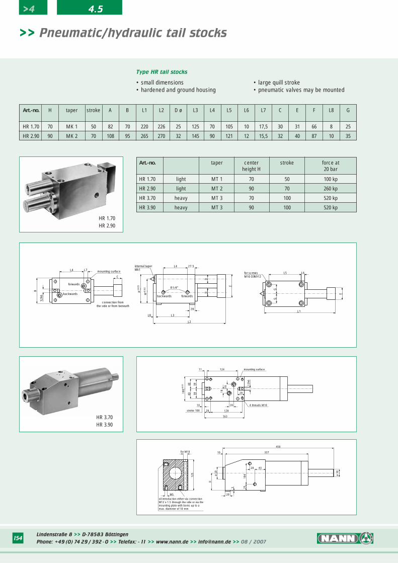
Lindenstraße 8 >> D-78583 Böttingen
Phone: +49 (0) 74 29 / 392 - 0 >> Telefax: - 11 >> www.nann.de >> [email protected] >> 08 / 2007154
>> Pneumatic/hydraulic tail stocks
• small dimensions• hardened and ground housing
Type HR tail stocks
• large quill stroke• pneumatic valves may be mounted
Art.-no. H taper stroke A B L1 L2 D ø L3 L4 L5 L6 L7 C E F L8 G
HR 1.70 70 MK 1 50 82 70 220 226 25 125 70 105 10 17,5 30 31 66 8 25
HR 2.90 90 MK 2 70 108 95 265 270 32 145 90 121 12 15,5 32 40 87 10 35
Art.-no. taper center stroke force atheight H 20 bar
HR 1.70 light MT 1 70 50 100 kp
HR 2.90 light MT 2 90 70 260 kp
HR 3.70 heavy MT 3 70 100 520 kp
HR 3.90 heavy MT 3 90 100 520 kp
HR 1.70HR 2.90
HR 3.70HR 3.90
>4 4.5
forwards
backwards
mounting surface
B
12h6
L4 L7
C
connection from�the side or from beneath
internal taper�Mk1
L4 27.5
R1/4"
backwards
F
DDA
±0.0
5
H±0
.02
L3
20
L8
L2
forwards
for screws�M10 DIN912
E
GG
L1
L5 L6
for M10
M5
125
20
3 25
337
450
10
104
4320
ø 30
H
ø 50
oil introduction either via connection�M12 x 1.5 through the side or via the�mounting plate with bores up to a�max. diameter of 10 mm
12411 mounting surface
383840
40
100±0
.01
10
stroke 100 26
20
128
163
4 threads M10
28
12h6
1818
![STANDARD CHUCKS SPANNTOP nova chuck - HAINBUCH · SPANNTOP nova combi deadlength size 32. Technical data I G AM C D A B ... Max. radial clamping force [kN] ... Clamping head protrusion](https://img.pdfslide.net/doc/110x75/5ade95387f8b9a595f8e5c02/standard-chucks-spanntop-nova-chuck-nova-combi-deadlength-size-32-technical-data.jpg)