Embed Size (px)
Citation preview

电气技术专业英语电气技术专业英语
朱一纶 主编朱一纶 主编
中国电力出版社中国电力出版社

Unit 15 User Manual Unit 15 User Manual
课件制作课件制作 : : 吴岱曦吴岱曦

IndexIndex
• TextText– 1. Safety Operation Guide 1. Safety Operation Guide – 2. PC-950 Front Panel Introduction (Fig 12. PC-950 Front Panel Introduction (Fig 1
5.1)5.1)
– 3. The Software Function 3. The Software Function

• Reading materialsReading materials– 1. Operational instruction (selection) 1. Operational instruction (selection) – 2. Material of PGA202/2032. Material of PGA202/203((sectionsection) )

• ExercisesExercises– 1. Put the Phrases into English 1. Put the Phrases into English – 2. Put the Phrases into Chinese 2. Put the Phrases into Chinese – 3. Sentence Translation3. Sentence Translation– 4. 4. TranslationTranslation

TextText

• As the modern education developing, As the modern education developing, various multimedia devices have various multimedia devices have been brought into many classrooms. been brought into many classrooms. For example: multimedia computer, For example: multimedia computer, VCR, VCD, projector, video VCR, VCD, projector, video presentation platform, electrical presentation platform, electrical curtain and amplifier etc. curtain and amplifier etc.

• It’s not convenient for the teacher to mIt’s not convenient for the teacher to manipulate all these above. The Educatioanipulate all these above. The Education Control System is developed to resolvn Control System is developed to resolve the problem. By controlling the multie the problem. By controlling the multimedia devices on a computer or the conmedia devices on a computer or the control panel, the course of control becometrol panel, the course of control becomes simple.s simple.

• This manual is applied to PC-950/ PC-This manual is applied to PC-950/ PC-3900 Education Control System.3900 Education Control System.

1. Safety Operation Guide1. Safety Operation Guide
• In order to guarantee the reliable operatIn order to guarantee the reliable operation of the equipments and safety of the sion of the equipments and safety of the stafftaff ,, please abide by the following proplease abide by the following proceeding in installation, using and mainteceeding in installation, using and maintenance:nance:

• 1) When installing the equipment, 1) When installing the equipment, make sure wire grounding in power make sure wire grounding in power cable is fine, DO NOT use double-cable is fine, DO NOT use double-legged socket, and ensure the legged socket, and ensure the voltage of input power supply voltage of input power supply consistent with which marked on consistent with which marked on the host. the host.

• 2) There is 110V/220V AC high voltage c2) There is 110V/220V AC high voltage components inside, please DO NOT opeomponents inside, please DO NOT open the casing without permission, in casn the casing without permission, in case of electric shock.e of electric shock.
• 3) DO NOT put the system equipment i3) DO NOT put the system equipment in the place too cold or too hot.n the place too cold or too hot.

• 4) As the power generating heat 4) As the power generating heat when running, the working when running, the working environment should be maintained environment should be maintained fine ventilation, in case of damage fine ventilation, in case of damage caused by overheat.caused by overheat.
• 5) Please cut off the general power 5) Please cut off the general power switch in humid weather or left switch in humid weather or left unused for long time.unused for long time.

• 6) Before following operation, ensure t6) Before following operation, ensure that the alternating current wire is pull hat the alternating current wire is pull out of the power supplyout of the power supply ::
– AA . . Take off or reship any components of Take off or reship any components of the equipment.the equipment.
– BB . . Take off or rejoin any pin or other link Take off or rejoin any pin or other link of the equipment.of the equipment.

• 7) As to non-professional or without 7) As to non-professional or without permission, please DO NOT try to permission, please DO NOT try to open the casing of the equipment, open the casing of the equipment, DO NOT repair it on your own, in DO NOT repair it on your own, in case of accident or increasing the case of accident or increasing the damage of the equipment.damage of the equipment.

• 8) DO NOT splash any chemistry substan8) DO NOT splash any chemistry substance or liquid in the equipment or around.ce or liquid in the equipment or around.

2. PC-950 Front Panel 2. PC-950 Front Panel Introduction (Fig 15.1)Introduction (Fig 15.1)
• 1. Control button1. Control button
• (1) Begin or Finish Class(1) Begin or Finish Class
• ① ① Press” CLASS BEGIN”, electrical Press” CLASS BEGIN”, electrical screen moves down and projector screen moves down and projector power on. 7 seconds later the power on. 7 seconds later the projector start working. Nothing projector start working. Nothing would perform when pressing “CLASS would perform when pressing “CLASS BEGIN” again.BEGIN” again.

Fig 15.1 Fig 15.1 PC-950 Front Panel PC-950 Front Panel

• ②②Press “CLASS OVER”, the system carry out Press “CLASS OVER”, the system carry out finish class order at a fixed time. When perforfinish class order at a fixed time. When perform the order, the electrical screen moves up anm the order, the electrical screen moves up and the projector will be cut off through RS232 cd the projector will be cut off through RS232 code. At this moment, only “CLASS BEGIN” is ode. At this moment, only “CLASS BEGIN” is controllable.controllable.
• NoticeNotice :: Only after pressing the “CLASS BEGOnly after pressing the “CLASS BEGIN” can other button be controllable.IN” can other button be controllable.

• (2) Projective Video Selection(2) Projective Video Selection
• ①①Press ”DVD/TV/VCR” in order to Press ”DVD/TV/VCR” in order to transmit AV signal from DVD to transmit AV signal from DVD to projector, and transmit the RS232 projector, and transmit the RS232 code (the ”DVD/TV/VCR” indicator code (the ”DVD/TV/VCR” indicator light turns red when switch to DVD) light turns red when switch to DVD)

• Press for the second time, it will Press for the second time, it will transmit AV signal from TV to projector transmit AV signal from TV to projector (the ”DVD/TV/VCR” indicator light turns (the ”DVD/TV/VCR” indicator light turns green when switch to TV); Press for the green when switch to TV); Press for the third time, it will transmit AV signal third time, it will transmit AV signal from VCR to projector (the from VCR to projector (the ”DVD/TV/VCR” indicator light turns ”DVD/TV/VCR” indicator light turns orange when switch to VCR). orange when switch to VCR).

• ②②Press ”PC/NOTEBOOK/VIS” in order Press ”PC/NOTEBOOK/VIS” in order to transmit VGA and audio signals from cto transmit VGA and audio signals from computer to projector, and send the RS2omputer to projector, and send the RS232 code(the ”PC/NOTEBOOK/VIS”32 code(the ”PC/NOTEBOOK/VIS” indiindicator light turns red when switch to PC) cator light turns red when switch to PC)

• Press for the second time, it will Press for the second time, it will transmit VGA and audio signals from transmit VGA and audio signals from laptop computer to Education Control laptop computer to Education Control System CREATOR projector (the System CREATOR projector (the ”PC/NOTEBOOK/VIS” indicator light ”PC/NOTEBOOK/VIS” indicator light turns green when switch to turns green when switch to NOTEBOOK) NOTEBOOK)

• Press for the third time, it will transmit VPress for the third time, it will transmit VGA signal from digital platform to projecGA signal from digital platform to projector (the ”PC/NOTEBOOK/VIS” indicatotor (the ”PC/NOTEBOOK/VIS” indicator light turns orange when switch to VIS).r light turns orange when switch to VIS).

• (3) Volume Control(3) Volume Control①①VOL+ output volume upVOL+ output volume up
②②VOL- output volume downVOL- output volume down

• (4) Projector Control Button(4) Projector Control Button①①ON——Send IR and RS232 codes to ON——Send IR and RS232 codes to
open the projector when press “ON”.open the projector when press “ON”.②②OFF——-Send IR and RS232 codes to OFF——-Send IR and RS232 codes to
close the projector when press “OFF”.close the projector when press “OFF”.③③VIDEO——Send IR and RS232 codes of VIDEO——Send IR and RS232 codes of
projector video when press “VIDEO”.projector video when press “VIDEO”.④④VGA——Send IR and RS232 codes of VGA——Send IR and RS232 codes of
computer signal when press “VGA”.computer signal when press “VGA”.

• (5) IR Learning(5) IR Learning• The buttons include “FUNCTION1The buttons include “FUNCTION1 、、 FUFU
NCTION2NCTION2 、、 ONON 、、 OFFOFF 、、 VIDEOVIDEO 、、 VGVGA”A”
• StepsSteps ::

• ①①Press ”IR LEARNING” for 2 seconds, iPress ”IR LEARNING” for 2 seconds, it will turn to IR Learning mode and other t will turn to IR Learning mode and other buttons become uncontrollable. The”Ibuttons become uncontrollable. The”IR LEARNING” will light for 10 seconds, aR LEARNING” will light for 10 seconds, and then it light off if not receives any IR cnd then it light off if not receives any IR code.ode.

• ②②Point the remote controller directly Point the remote controller directly to IR receiving window and press to IR receiving window and press corresponding buttons, then 6 IR corresponding buttons, then 6 IR learning buttons blink after receiving learning buttons blink after receiving the IR code. It will quit learning mode the IR code. It will quit learning mode 10 seconds later when not receives 10 seconds later when not receives any IR code.any IR code.

• ③③Press the learning button within 10 Press the learning button within 10 seconds in order to make IR learning seconds in order to make IR learning successful. Then it lights off after successful. Then it lights off after blinking 3 times.blinking 3 times.

• 2. Portable Computer VGA Signal 2. Portable Computer VGA Signal Input PortInput Port
• Connect to portable computer VGA Connect to portable computer VGA port, adopting standard 15HDF port, adopting standard 15HDF interface.interface.
• 3. LAN3. LAN
• Directly connect to the Ethernet port Directly connect to the Ethernet port on rear panel.on rear panel.

• 4. Electric lock4. Electric lock• Only a special key can open this lock. It eOnly a special key can open this lock. It e
quals to the function of “begin class” quals to the function of “begin class” and”finish class”. No button is controland”finish class”. No button is controllable when locked.lable when locked.

• 5. USB5. USB• Directly connect to the USB port on Directly connect to the USB port on
rear panel.rear panel.• 6. AV Signal Input6. AV Signal Input• Input the AV signal from external Input the AV signal from external
devices to the system. By default devices to the system. By default setting, the AV signal transmits to setting, the AV signal transmits to amplifier or projector output.amplifier or projector output.

• 7. Microphone Port7. Microphone Port
• Connect to microphoneConnect to microphone

3. The Software Function3. The Software Function
• The main interface of education The main interface of education control system software is shown in control system software is shown in Fig 15.2Fig 15.2

Fig 15.2 Fig 15.2 The main interface of edThe main interface of education control system softwareucation control system software

• 1.CLASS BEGIN1.CLASS BEGIN
• Left click mouse to begin class. Right Left click mouse to begin class. Right click mouse to open following click mouse to open following window (Fig 15.3), and you can set window (Fig 15.3), and you can set whether allow “Projector Action” and whether allow “Projector Action” and “Projector Screen”. Tick what you “Projector Screen”. Tick what you need and click “Download” to need and click “Download” to confirm.confirm.
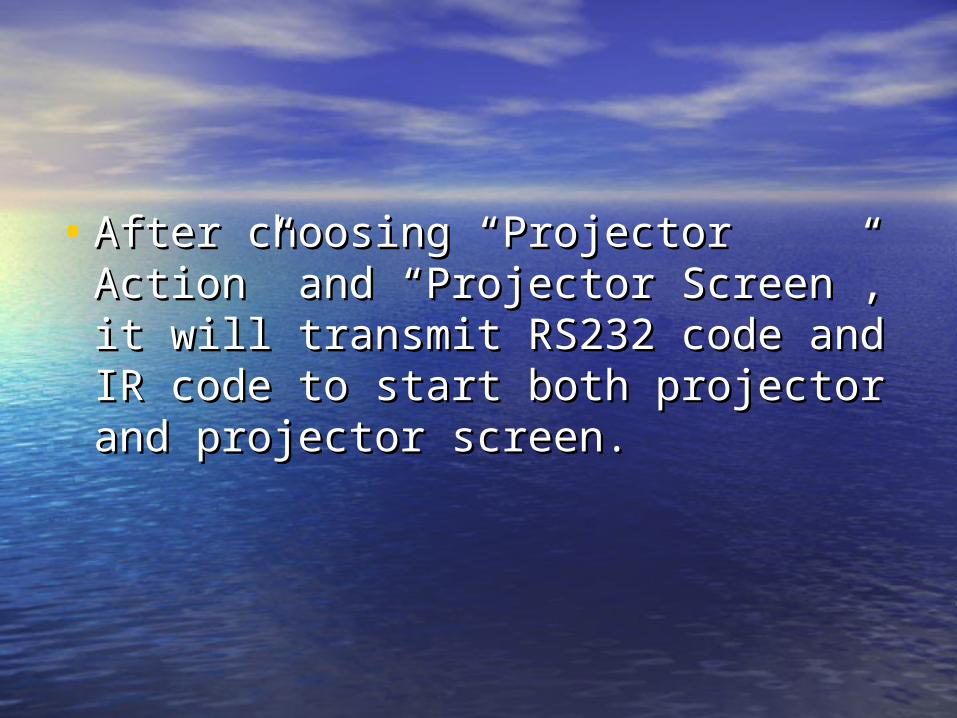
• After choosing “Projector Action” and After choosing “Projector Action” and “Projector Screen”, it will transmit “Projector Screen”, it will transmit RS232 code and IR code to start both RS232 code and IR code to start both projector and projector screen.projector and projector screen.

Fig 15.3 class begin linkage Fig 15.3 class begin linkage setup window setup window

• 2.CLASS OVER2.CLASS OVER
• Left click mouse to finish class. Right Left click mouse to finish class. Right click mouse to open following click mouse to open following window (Fig 15.4), and you can set window (Fig 15.4), and you can set whether allow “Projector Action” and whether allow “Projector Action” and “Projector Screen”. Tick what you “Projector Screen”. Tick what you need and click “Download” to need and click “Download” to confirm.confirm.

You can also set the delaying time. You can also set the delaying time. • Setting range Class OverSetting range Class Over :: 00 ~~ 60min60min• Setting range ProjectorSetting range Projector : : 22 ~~ 6min6min• Then confirm it.Then confirm it.

After choosing “Projector Action” and After choosing “Projector Action” and “Projector Screen”, it will transmit “Projector Screen”, it will transmit RS232 code and IR code to close RS232 code and IR code to close both projector and projector screen.both projector and projector screen.

Fig 15.4 class begin linkage Fig 15.4 class begin linkage setting window setting window

This is the End of the TextThis is the End of the Text

Reading materialsReading materials
1. Operational instruction 1. Operational instruction (selection)(selection)
• Usually software operational manuals Usually software operational manuals explain their operational processes in explain their operational processes in detail with graphic example, here are detail with graphic example, here are some examples which are selected some examples which are selected from protel tutorial. from protel tutorial.

1. Schematic Layout- Adding 1. Schematic Layout- Adding NetsNets
• On simple projects, it makes sense to On simple projects, it makes sense to run wires making connections, but on run wires making connections, but on larger projects this often makes larger projects this often makes things very cluttered, difficult to things very cluttered, difficult to make changes, and often results in make changes, and often results in errors due to wires crossing.errors due to wires crossing.

• Draw a small wire extending from VSS (GNDraw a small wire extending from VSS (GND), and a small wire from the other pin on tD), and a small wire from the other pin on the pin header (as shown in Fhe pin header (as shown in Fig 15.5)ig 15.5). Click . Click the ‘NET’ icon in the toolbar (Fig 15.6) athe ‘NET’ icon in the toolbar (Fig 15.6) and place this text on both lines, labeling thnd place this text on both lines, labeling them both GND.em both GND.
• This is the same exact thing as actually ruThis is the same exact thing as actually running wires between them. Protel knows tnning wires between them. Protel knows that these two pins should be connected.hat these two pins should be connected.

Fig 15.5 connect wit NETS Fig 15.5 connect wit NETS

Fig 15.6 Click the ‘NET’ icon in Fig 15.6 Click the ‘NET’ icon in the toolbar the toolbar

• You should now have the figure (Fig You should now have the figure (Fig 15.5). Notice the blue dots on pin 12 15.5). Notice the blue dots on pin 12 and pin 11, the dots appear when and pin 11, the dots appear when more there is a connect of more than more there is a connect of more than 2 areas. In the case of the blue dot 2 areas. In the case of the blue dot on the left, this connects pin 12, pin on the left, this connects pin 12, pin 31, and GND all together.31, and GND all together.

• The usefulness of nets cannot be The usefulness of nets cannot be over emphasized here, it may seem over emphasized here, it may seem like extra work, but DO IT!! like extra work, but DO IT!!

1.1. Allows for cell design of layout, This makes Allows for cell design of layout, This makes design neat, orderly, easy to troubleshoot.design neat, orderly, easy to troubleshoot.
2.2. Looks professional.(Fig 15.7) Looks professional.(Fig 15.7) 3.3. Major changes such as changing an 8 Major changes such as changing an 8
connection port from port A to B is simple connection port from port A to B is simple to just move the NETS, rather than rewire to just move the NETS, rather than rewire 8 different wires.8 different wires.
4.4. Can create multiple schematic documents Can create multiple schematic documents (advised), and link nets across schematics(advised), and link nets across schematics

FFig 15.7 ig 15.7 Schematic Layout- UsinSchematic Layout- Using Netsg Nets

2. Creating Custom Parts 2. Creating Custom Parts
• Sometimes a part will be required Sometimes a part will be required and no library associated with it. For and no library associated with it. For this, we need to make both a this, we need to make both a schematic and a PCB footprint for the schematic and a PCB footprint for the part. Following are some steps of part. Following are some steps of making a schmatic for a part.making a schmatic for a part.

• From the file menu(Fig 15From the file menu(Fig 15.8 ).8 ), create , create a new schematic library, and a new a new schematic library, and a new PCB library. Save these libraries PCB library. Save these libraries under a name you will remember.under a name you will remember.

Fig 15.8 File menu Fig 15.8 File menu

• Select/Highlight the schematic library Select/Highlight the schematic library you just created and click ‘SCH you just created and click ‘SCH Library’ in the bottom corner of the Library’ in the bottom corner of the project menu.(Fig 15.9 )project menu.(Fig 15.9 )

Fig 15.9 Select/Highlight Fig 15.9 Select/Highlight

• This shows information about the This shows information about the schematic library and a list of the schematic library and a list of the parts inside the library. Click the ADD parts inside the library. Click the ADD button to add a new part.button to add a new part.
• Click on the place rectangle for our Click on the place rectangle for our part(Fig 15.10). Keep in mind this is part(Fig 15.10). Keep in mind this is what we will see on our schematic.what we will see on our schematic.

Fig 15.10 the place Fig 15.10 the place rectanglerectangle

2. Material of PGA202/2032. Material of PGA202/203 (( ssectionection ))• Digitally Controlled Programmable-Digitally Controlled Programmable-
Gain Gain
INSTRUMENTATION AMPLIFIER (Fig INSTRUMENTATION AMPLIFIER (Fig 15.11(a)) 15.11(a))
• The PGA202 is a monolithic The PGA202 is a monolithic instrumentation amplifier with digitally instrumentation amplifier with digitally controlled gains of 1, 10, 100, and 1000. controlled gains of 1, 10, 100, and 1000. The PGA203 provides gains of 1, 2, 4, and The PGA203 provides gains of 1, 2, 4, and 8. 8.

• Both have TTL or CMOS-compatible Both have TTL or CMOS-compatible inputs for easy microprocessor inputs for easy microprocessor interface. Both have FET inputs and a interface. Both have FET inputs and a new transconductance circuitry that new transconductance circuitry that keeps the bandwidth nearly constant keeps the bandwidth nearly constant with gain. Gain and offsets are laser with gain. Gain and offsets are laser trimmed to allow use without any trimmed to allow use without any external components. external components.

• Both amplifiers are available in Both amplifiers are available in ceramic or plastic packages. The ceramic or plastic packages. The ceramic package is specified over ceramic package is specified over the full industrial temperature range the full industrial temperature range while the plastic package covers the while the plastic package covers the commercial range.commercial range.

Fig 15.11 Fig 15.11 PGA202/203 and its diaPGA202/203 and its diagram gram

• A simplified diagram of the A simplified diagram of the PGA202/203 is shown in Fig 15.11(b). PGA202/203 is shown in Fig 15.11(b). The design consists of a digitally The design consists of a digitally controlled, differential controlled, differential transconductance front end stage transconductance front end stage using precision FET buffers and the using precision FET buffers and the classical transimpedance output classical transimpedance output stage. stage.

• Gain switching is accomplished with Gain switching is accomplished with a novel current steering technique a novel current steering technique that allows for fast settling when that allows for fast settling when changing gains. The result is a high changing gains. The result is a high performance, programmable performance, programmable instrumentation amplifier with instrumentation amplifier with excellent speed and gain accuracy.excellent speed and gain accuracy.
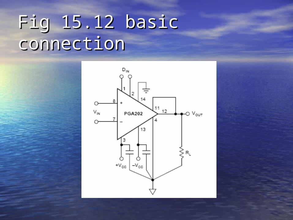
Fig 15.12 basic connectionFig 15.12 basic connection

• Fig 15.12 shows the proper Fig 15.12 shows the proper connections for power supply and connections for power supply and signal. The power supplies should be signal. The power supplies should be decoupled with 1mF tantalum decoupled with 1mF tantalum capacitors placed as close to the capacitors placed as close to the amplifier as possible for maximum amplifier as possible for maximum performance. performance.

• To avoid gain and CMR errors To avoid gain and CMR errors introduced by the external introduced by the external components, you should connect the components, you should connect the grounds as indicated. Any resistance grounds as indicated. Any resistance in the sense line (pin 11) or the VREF in the sense line (pin 11) or the VREF line (pin 4) will lead to a gain error, line (pin 4) will lead to a gain error, so these lines should be kept as short so these lines should be kept as short as possible. as possible.

• To also maintain stability, avoid To also maintain stability, avoid capacitance from the output to the capacitance from the output to the input or the offset adjust pins. input or the offset adjust pins.

This is the End ofThis is the End of the Reading materials the Reading materials

ExercisesExercises
• Ready to go?Ready to go?

1. Put the Phrases into 1. Put the Phrases into EnglishEnglish
• 11 )多媒体设备)多媒体设备• 22 )电子窗帘)电子窗帘• 33 )安装设备)安装设备• 44 )触电)触电• 55 )设备损坏)设备损坏
Show the Answer

• 66 )按下按钮 )按下按钮 • 77 )录像机信号 )录像机信号 • 88 )指示灯)指示灯• 99 )遥控器 )遥控器 • 1010 )单击鼠标)单击鼠标
Show the Answer

2. Put the Phrases into 2. Put the Phrases into ChineseChinese
• 11 )) video presentation platformvideo presentation platform
• 22 )) abide by the following proceedingabide by the following proceeding• 33 )) working environmentworking environment• 44 )) non-professionalnon-professional• 55 )) chemistry substancechemistry substance
Show the Answer

• 66 )) carry out finish class ordercarry out finish class order• 77 )) light turns redlight turns red• 88 )) uncontrollable buttonuncontrollable button• 99 )) double click mousedouble click mouse
• 10)10) delaying time delaying time
Show the Answer

3. Sentence Translation3. Sentence Translation
• 1)1) It’s not convenient for the teacher t It’s not convenient for the teacher to manipulate all these above.o manipulate all these above.
• 11 )教师要去操作所有这些设备有时不太方)教师要去操作所有这些设备有时不太方便。 便。

• 2) In order to guarantee the reliable operation 2) In order to guarantee the reliable operation of the equipments and safety of the staffof the equipments and safety of the staff ,, pleplease abide by the following proceeding in instalase abide by the following proceeding in installation, using and maintenance.lation, using and maintenance.
• 22 )为了保证设备可靠工作和人身安全,在)为了保证设备可靠工作和人身安全,在安装、使用和维护过程中请按照如下步骤安装、使用和维护过程中请按照如下步骤进行操作 。进行操作 。
• 3) Only after pressing the “CLASS 3) Only after pressing the “CLASS BEGIN” can other button be BEGIN” can other button be controllable.controllable.
• 33 )只有按下了“上课”按钮后,其它按钮)只有按下了“上课”按钮后,其它按钮才受控。 才受控。

• 4) Point the remote controller directly to 4) Point the remote controller directly to IR receiving window and press correspoIR receiving window and press corresponding buttons.nding buttons.
• 44 )把遥控器直接对准)把遥控器直接对准 IRIR 接受窗口,按下接受窗口,按下相应的按钮 。相应的按钮 。

• 55 )) Press the learning button within 10 Press the learning button within 10 seconds in order to make IR learning sucseconds in order to make IR learning successful.cessful.
• 55 )在)在 1010 秒内按下学习按钮使秒内按下学习按钮使 IRIR 学习成功。学习成功。

44 .. TranslationTranslation
• 把下列把下列 PGA202/203PGA202/203 器芯片的特点和应用器芯片的特点和应用译成中文。译成中文。 (( 有时用户说明书为了吸引大家有时用户说明书为了吸引大家的注意,用很简洁的方法列出产品的特点的注意,用很简洁的方法列出产品的特点和应用和应用 ,, 这里就是一个例子这里就是一个例子 )) 。。

FEATURESFEATURES
• DIGITALLY PROGRAMMABLE GAINS:DIGITALLY PROGRAMMABLE GAINS:– DECADE MODEL—PGA202DECADE MODEL—PGA202
•GAINS OF 1, 10, 100, 1000GAINS OF 1, 10, 100, 1000
– BINARY MODEL—PGA203BINARY MODEL—PGA203•GAINS OF 1, 2, 4, 8GAINS OF 1, 2, 4, 8
• LOW BIAS CURRENT: 50pA maxLOW BIAS CURRENT: 50pA max

• FAST SETTLING: 2ms to 0.01%FAST SETTLING: 2ms to 0.01%
• LOW NON-LINEARITY: 0.012% maxLOW NON-LINEARITY: 0.012% max
• HIGH CMRR: 80dB minHIGH CMRR: 80dB min
• NEW TRANSCONDUCTANCE NEW TRANSCONDUCTANCE CIRCUITRYCIRCUITRY
• LOW COSTLOW COST

APPLICATIONSAPPLICATIONS
• DATA ACQUISITION SYSTEMSDATA ACQUISITION SYSTEMS
• AUTO-RANGING CIRCUITSAUTO-RANGING CIRCUITS
• DYNAMIC RANGE EXPANSIONDYNAMIC RANGE EXPANSION
• REMOTE INSTRUMENTATIONREMOTE INSTRUMENTATION
• TEST EQUIPMENTTEST EQUIPMENT
Show the Answer

This is the End of the This is the End of the ExercisesExercises
Good work everyone !!!Good work everyone !!!(( 习题答案仅供参考习题答案仅供参考 ))