Embed Size (px)
Citation preview
WLTP-2012-006-Draft test procedure incl. test conditions-DC
PROPOSED ANNEX 7TEST PROCEDURE15.02.2012
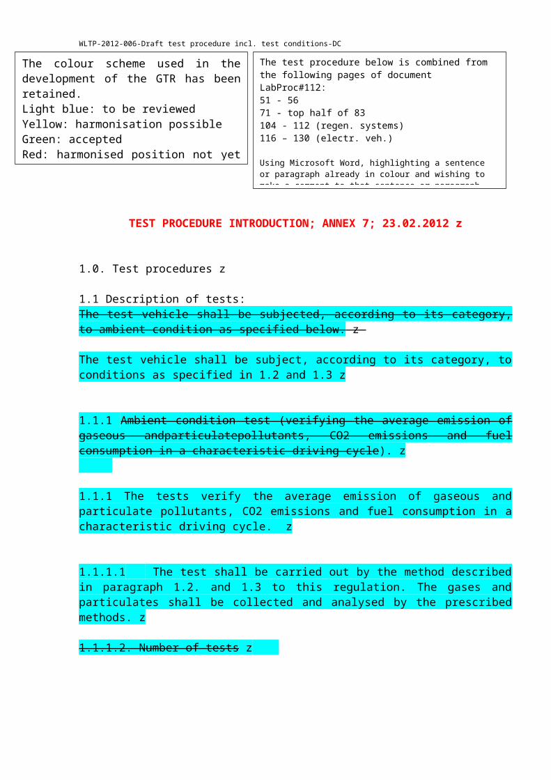
TEST PROCEDURE INTRODUCTION; ANNEX 7; 23.02.2012 z
1.0. Test procedures z
1.1 Description of tests:The test vehicle shall be subjected, according to its category, to ambient condition as specified below. z
The test vehicle shall be subject, according to its category, to conditions as specified in 1.2 and 1.3 z
1.1.1 Ambient condition test (verifying the average emission of gaseous andparticulatepollutants, CO2 emissions and fuel consumption in a characteristic driving cycle). z
1.1.1 The tests verify the average emission of gaseous and particulate pollutants, CO2 emissions and fuel consumption in a characteristic driving cycle. z
1.1.1.1 The test shall be carried out by the method described in paragraph 1.2. and 1.3 to this regulation. The gases and particulates shall be collected and analysed by the prescribed methods. z
1.1.1.2. Number of tests z
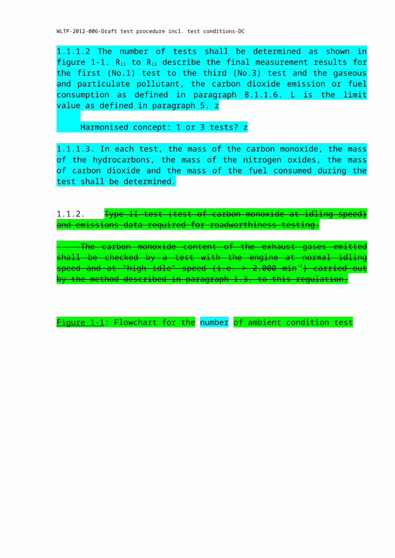
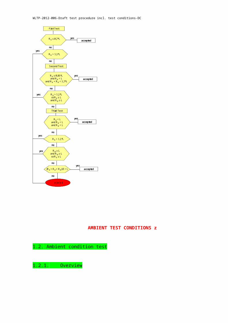
1.1.1.2 The number of tests shall be determined as shown in figure 1-1. R i1 to Ri3 describe the final measurement results for the first (No.1) test to the third (No.3) test and the gaseous and particulate pollutant, the carbon dioxide emission or fuel consumption as defined in paragraph 8.1.1.6. L is the limit value as defined in paragraph 5. z
Harmonised concept: 1 or 3 tests? z
1.1.1.3. In each test, the mass of the carbon monoxide, the mass of the hydrocarbons, the mass of the nitrogen oxides, the mass of carbon dioxide and the mass of the fuel consumed during the test shall be determined.
The colour scheme used in the development of the GTR has been retained.Light blue: to be reviewedYellow: harmonisation possibleGreen: acceptedRed: harmonised position not yet possibleB&W: not yet checked
The test procedure below is combined from the following pages of document LabProc#112:51 - 5671 - top half of 83104 - 112 (regen. systems)116 – 130 (electr. veh.)
Using Microsoft Word, highlighting a sentence or paragraph already in colour and wishing to make a comment to that sentence or paragraph leads to that colour being defaulted to pink. In other words, any significance attached to the various colours is lost. To get around this, in this document, a single dummy letter (in this case, “z”) has been added to which a comment can be attached.
WLTP-2012-006-Draft test procedure incl. test conditions-DC
1.1.2. Type II test (test of carbon monoxide at idling speed) and emissions data required for roadworthiness testing.
The carbon monoxide content of the exhaust gases emitted shall be checked by a test with the engine at normal idling speed and at "high idle" speed (i.e. > 2.000 min -1) carried out by the method described in paragraph 1.3. to this regulation.
Figure 1-1: Flowchart for the number of ambient condition test
First Test
Ri1 ≤ 0,7*L yes
no
accepted
Ri1 > 1,1*Lyes
no
Second Test
Ri1 ≤ 0,85*Land Ri2 < L
and Ri1 + Ri2 < 1,7*L
yesaccepted
no
Ri2 > 1,1*Lor Ri1 ≥ L
and Ri2 ≥ L
yes
no
Third Test
Ri1 < Land Ri2 < Land Ri3 < L
yesaccepted
no
Ri1 > 1,1*Lyes
no
Ri3 ≥ Land Ri2 ≥ Lor Ri1 ≥ L
yes
no
(Ri1 + Ri2 + Ri3)/3 < L
no
yesaccepted
rejected
AMBIENT TEST CONDITIONS z
WLTP-2012-006-Draft test procedure incl. test conditions-DC
1.2. Ambient condition test
1.2.1. Overview
1.2.1.1. Ambient condition test consists of prescribed sequences of dynamometer preparation, fuelling, soaking, and operating conditions.
1.2.1.2. The test is designed to determine gaseous and particulate emissions, and fuel consumption.z The test consists of engine start-ups and vehicle operation on a chassis dynamometer, through a specified driving cycle. A proportional part of the diluted exhaust emissions is collected continuously for subsequent analysis, using a constant volume (variable dilution) sampler (CVS). z
Definition of new or alternative equipment? AP
1.2.1.3. Except in cases of component malfunction or failure, all emission control systems installed on or incorporated in a tested vehicle shall be functioning during all procedures.
1.2.1.4. Background concentrations are measured for all species for which emissions measurements are made. For exhaust testing, this requires sampling and analysis of the dilution air.
1.2.1.4.1 Background particulate mass measurement
The particulate background level of the dilution air may be determined by passing filtered dilution air through the particulate filter. This shall be drawn from the same point as the particulate sample. One measurement may be performed prior to or after the test. Particulate mass measurements may be corrected by subtracting the background contribution from the dilution system. The permissible background contribution shall be ≤ 1 mg/km (or equivalent mass on the filter). If the background exceeds this level, the default figure of 1 mg/km (or equivalent mass on the filter) shall be employed. Where subtraction of the background contribution gives a negative result, the particulate mass result shall be considered to be zero.
1.2.1.4.2. Background particle number measurements --> PM/PN group
The subtraction of background particle numbers may be determined by sampling dilution air drawn from a point downstream of the particle and hydrocarbon filters into the particle number measurement system. Background correction of particle number measurements shall not be allowed for type approval, but may be used at the manufacturer's request for conformity of production and in service conformity where there are indications that tunnel contribution is significant.
TEST CELL EQUIPMENT
WLTP-2012-006-Draft test procedure incl. test conditions-DC
1.2.2. General test cell equipment
1.2.2.1. Variables to be measured z
1.2.2.1.1. The following temperatures shall be measured with an accuracy of 1.5 K:(a) Test cell ambient air(b) Intake air to the engine(c) Dilution and sampling system temperatures as required for emissions
measurement systems defined in Appendices 2 to 5 of this annex. z
1.2.2.1.2. The atmospheric pressure shall be measurable to within 0.1 kPa.
1.2.2.1.3. The absolute humidity (Ha) shall be measurable to within 5 per cent.
1.2.2.2. Test room and soak area
1.2.2.2.1. Test room
1.2.2.2.1.1. The test room with the chassis dynamometer and the gas sample collection device shall have a temperature setpoint [of 298 K] the tolerance of the actual value shall be within ± 5 K. The room temperature shall be measured continuously in the vicinity of vehicle cooling fan (1 Hz). z z
1.2.2.2.1.2. The absolute humidity (Ha) of either the air in the test cell or the intake air of the engine shall be such that:
5.5 ≤ Ha ≤ 12.2 (g H2O/kg dry air)
The humidity shall be measured continuously (1 Hz).
1.2.2.2.2. Soak area
1.2.2.2.2.1. The soak area shall have a temperature setpoint of [298 K] , the tolerance of the actual value shall be within ± 5 K and shall enable to precondition the test vehicle in accordance with paragraph 1.2.4.
TEST VEHICLE
1.2.3. Test vehicle (Light-Duty Vehicle)
1.2.3.1. GeneralThe test vehicle shall conform in all its components with the production series, or, if the vehicle is different from the production series, a full description shall be given in the test report. In selecting the test vehicle, the manufacturer and test authority shall agree which light-duty vehicle test model is representative for a related Test Group of vehicles.
1.2.3.2. Run-in
WLTP-2012-006-Draft test procedure incl. test conditions-DC
The vehicle must be presented in good mechanical condition. It must have been run-in and driven between 3000 km and 15 000 km before the test. The engine, transmission and vehicle shall be properly run-in, in accordance with the manufacturer’s requirements.
ADJUSTMENTS
1.2.4. Adjustments z
1.2.4.1. Dynamometer settings and verification (see Annex XYZ) z
1.2.4.2. Dynamometer operation mode z
1.2.4.2.1. Vehicle dyno operation mode can be activated on manufacturer’s request. z
1.2.4.2.2. A “dyno operation mode”, if any, shall be activated by using a manufacturer's instruction (e.g. using vehicle steering buttons in a special "pressing order", by using the manufacturer work shop tester, or fuse removal).The manufacturer shall provide to the approval authority a list of the deactivated devices and justification of the deactivation.Auxiliaries shall be switched off/deactivated during dyno operation.
1.2.4.2.3. “Dyno operation mode” shall not activate, modulate, delay or deactivate the operation of any part, that affects the emissions and fuel consumption under the test conditions. Any device that affects the operation on a chassis dyno can be set in a certain condition to ensure a proper operation.Activation or not of the mode shall be recorded in the test report.
1.2.4.3. The exhaust device shall not exhibit any leak likely to reduce the quantity of gas collected, which quantity shall be that emerging from the engine.
1.2.4.4. The tightness of the intake system may be checked to ensure that carburation is not affected by an accidental intake of air. z
1.2.4.5. The settings of the engine and of the vehicle's controls shall be those prescribed by the manufacturer. This requirement also applies, in particular, to the settings for idling (rotation speed and carbon monoxide content of the exhaust gases), for the cold start device and for the exhaust gas cleaning system.
1.2.4.6. The vehicle to be tested, or an equivalent vehicle, shall be fitted, if necessary, with a device to permit the measurement of the characteristic parameters necessary for chassis dynamometer setting, in conformity with paragraph 5. of this annex. z
3.2.6. The technical service responsible for the tests may verify that the vehicle's performance conforms to that stated by the manufacturer, that it can be used for normal driving and, more particularly, that it is capable of starting when cold and when hot.
WLTP-2012-006-Draft test procedure incl. test conditions-DC
1.2.4.7. Tyres shall be of a type specified as original equipment by the vehicle manufacturer. Tyre pressure may be increased by up to 50 per cent above the pressure specified in chapter X.X.X of Annex ZZ. The actual pressure used shall be recorded in the test report.
1.2.4.8. Specification of the reference fuelECE R 83-06: 3.3.1. The appropriate reference fuel as defined in Annex XYZ to this Regulation shall be used for testing.
Vehicles that are fuelled either with petrol or with LPG or NG/biomethane shall be tested according to Annex XY with the appropriate reference fuel(s) as defined in Annex XYZ.
1.2.4.9. Test vehicle preparation
1.2.4.9.1. The vehicle shall be approximately horizontal during the test so as to avoid any abnormal distribution of the fuel.
1.2.4.9.2. Dyno operation mode (as specified in chapter XYZ) and coast down mode (as specified in Annex XYZ) shall be switched on, if any. z
1.2.4.9.3. If necessary, the manufacturer shall provide additional fittings and adapters, as required to accommodate a fuel drain at the lowest point possible in the tank(s) as installed on the vehicle, and to provide for exhaust sample collection.
CALIBRATION OF ANALYSERS
Calibration of analysers z
PRELIMINARY TESTING CYCLES
1.2.5. Preliminary testing cycles (move to dynamometer settings)
1.2.5.1. Preliminary testing cycles can be carried out if necessary to determine how best to actuate the accelerator and brake controls so as to achieve a cycle approximating to the theoretical cycle within the prescribed limits under which the cycle is carried out.
TEST VEHICLE PRECONDITIONING
1.2.6. Test vehicle preconditioning
1.2.6.1. The fuel tank(s) shall be filled with the specified test fuel. If the existing fuel in thefuel tank(s) does not meet the specifications contained in paragraph XYZ above, the existing fuel shall be drained prior to the fuel fill. The test fuel shall be at a temperature less than or equal to
WLTP-2012-006-Draft test procedure incl. test conditions-DC
289 K (+16 °C). For the above operations, the evaporative emission control system shall neither be abnormally purged nor abnormally loaded.
1.2.6.2. Battery chargingBefore the pre-conditioning test cycle, the battery shall be fully charged. The battery shall not be charged again before the official testing.
1.2.6.3. The test vehicle shall be moved to the test cell and the following operations performed:
1.2.6.3.1. The test vehicle shall be placed, either by being driven or pushed, on a dynamometer and operated through the cycles as specified in paragraph XYZ. The vehicle need not be cold, and may be used to set dynamometer power.The dynamometer setting shall be the one indicated in paragraph XYZ
Pre-conditioning cycle (DHC input needed)
1.2.6.3.2. The preconditioning consists of a driving cycle (t.b.d.) paragraph XYZ
1.2.6.3.3. During the preconditioning the test cell temperature shall be the same as defined for the ambient condition test (5.2.2.2.)
1.2.6.3.4. The drive-wheel tyre pressure shall be set in accordance with the provisions of paragraph XYZ
STARTING THE ENGINE, DRIVING z
1.2.6.4. The engine shall be started up by means of the devices provided for this purpose according to the manufacturer's instructions, as incorporated in the drivers' handbook of production vehicles. z
1.2.6.4.1. The first cycle starts on the initiation of the engine start-up procedure.
1.2.6.4.2. In cases where LPG or NG/biomethane is used as a fuel, it is permissible that the engine is started on petrol and switched to LPG or NG/biomethane after a predetermined period of time which cannot be changed by the driver.
1.2.6.4.3. Idling z
1.2.6.4.4. Manual-shift or semi-automatic gearbox, see Tables XYZ. z
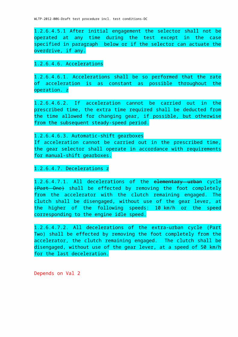
1.2.6.4.5. Automatic-shift gearbox1.2.6.4.5.1 After initial engagement the selector shall not be operated at any time during the test except in the case specified in paragraph below or if the selector can actuate the overdrive, if any.
1.2.6.4.6. Accelerations
WLTP-2012-006-Draft test procedure incl. test conditions-DC
1.2.6.4.6.1. Accelerations shall be so performed that the rate of acceleration is as constant as possible throughout the operation. z
1.2.6.4.6.2. If acceleration cannot be carried out in the prescribed time, the extra time required shall be deducted from the time allowed for changing gear, if possible, but otherwise from the subsequent steady-speed period.
1.2.6.4.6.3. Automatic-shift gearboxesIf acceleration cannot be carried out in the prescribed time, the gear selector shall operate in accordance with requirements for manual-shift gearboxes.
1.2.6.4.7. Decelerations z
1.2.6.4.7.1. All decelerations of the elementary urban cycle (Part One) shall be effected by removing the foot completely from the accelerator with the clutch remaining engaged. The clutch shall be disengaged, without use of the gear lever, at the higher of the following speeds: 10 km/h or the speed corresponding to the engine idle speed.
1.2.6.4.7.2. All decelerations of the extra-urban cycle (Part Two) shall be effected by removing the foot completely from the accelerator, the clutch remaining engaged. The clutch shall be disengaged, without use of the gear lever, at a speed of 50 km/h for the last deceleration.
Depends on Val 2
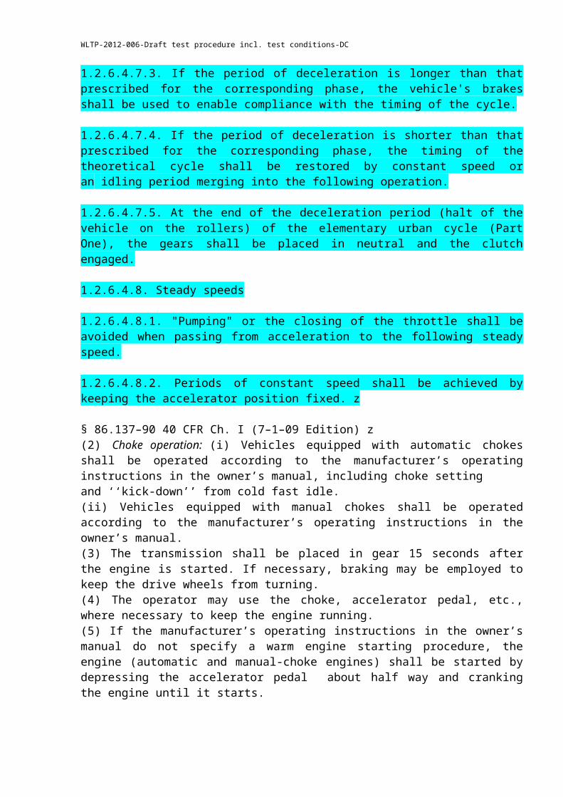
1.2.6.4.7.3. If the period of deceleration is longer than that prescribed for the corresponding phase, the vehicle's brakes shall be used to enable compliance with the timing of the cycle.
1.2.6.4.7.4. If the period of deceleration is shorter than that prescribed for the corresponding phase, the timing of the theoretical cycle shall be restored by constant speed or an idling period merging into the following operation.
1.2.6.4.7.5. At the end of the deceleration period (halt of the vehicle on the rollers) of the elementary urban cycle (Part One), the gears shall be placed in neutral and the clutch engaged.
1.2.6.4.8. Steady speeds
1.2.6.4.8.1. "Pumping" or the closing of the throttle shall be avoided when passing from acceleration to the following steady speed.
1.2.6.4.8.2. Periods of constant speed shall be achieved by keeping the accelerator position fixed. z
§ 86.137–90 40 CFR Ch. I (7–1–09 Edition) z(2) Choke operation: (i) Vehicles equipped with automatic chokes shall be operated according to the manufacturer’s operating instructions in the owner’s manual, including choke settingand ‘‘kick-down’’ from cold fast idle.
WLTP-2012-006-Draft test procedure incl. test conditions-DC
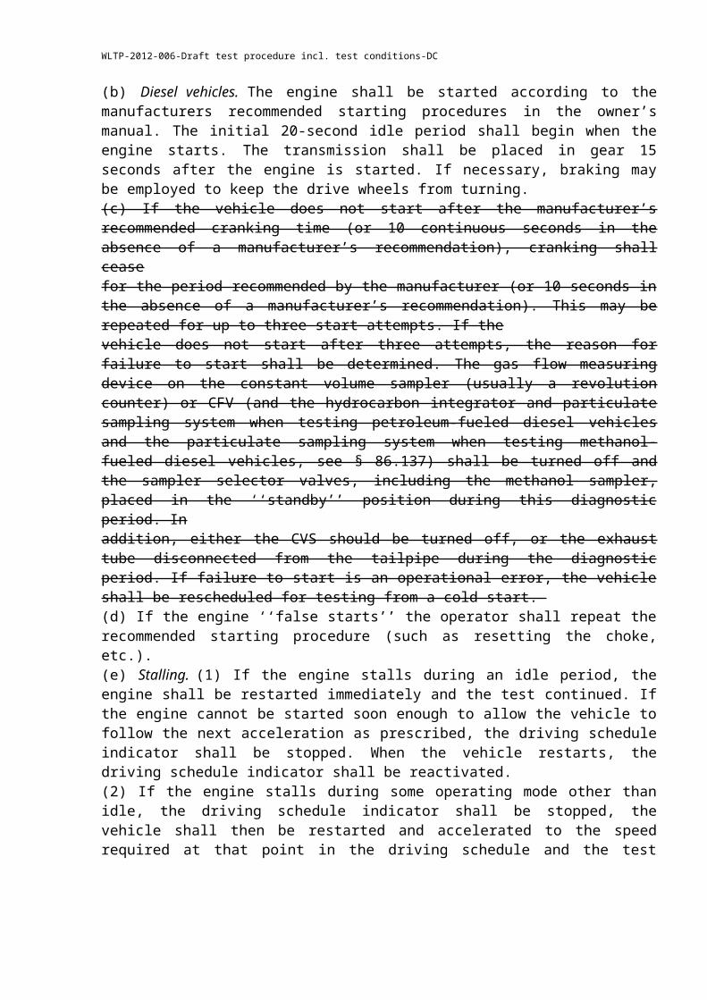
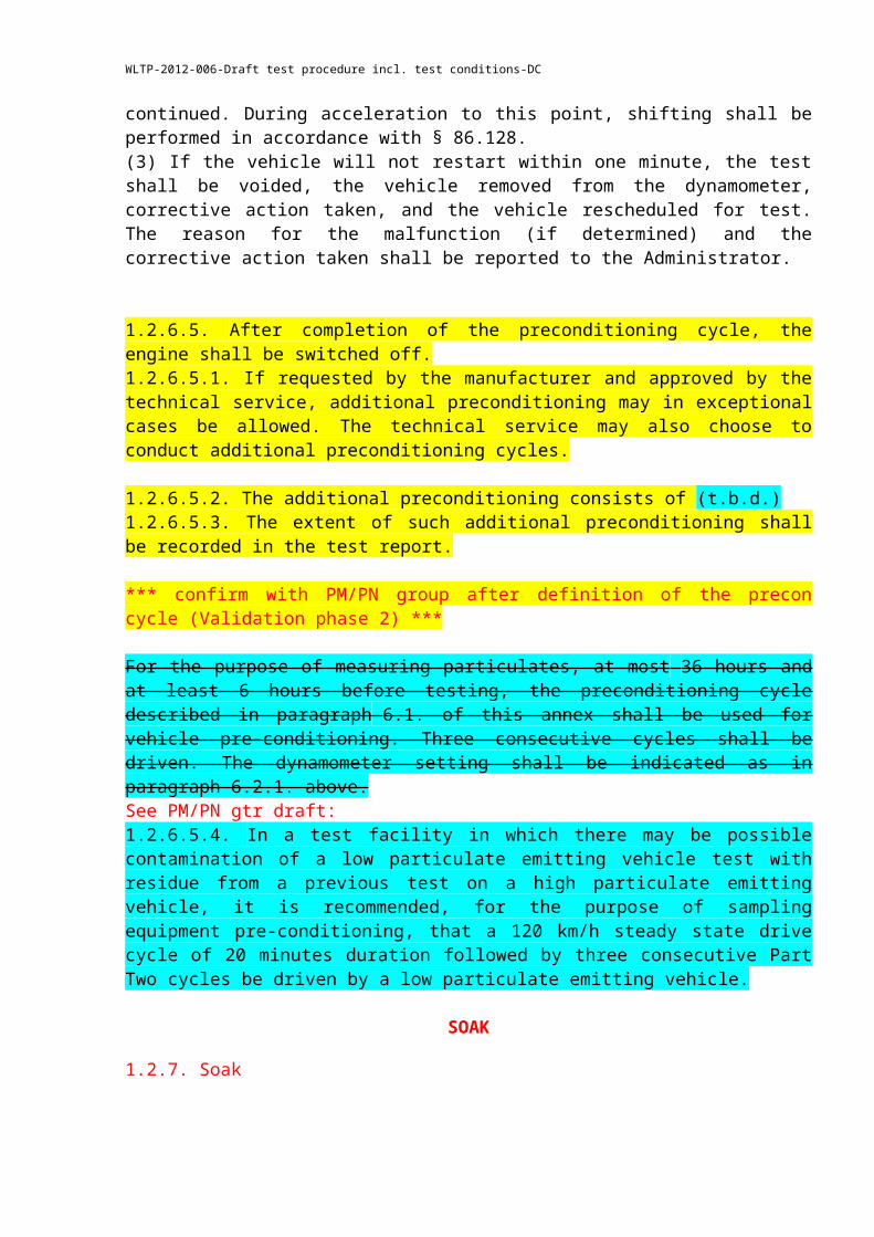
(ii) Vehicles equipped with manual chokes shall be operated according to the manufacturer’s operating instructions in the owner’s manual.(3) The transmission shall be placed in gear 15 seconds after the engine is started. If necessary, braking may be employed to keep the drive wheels from turning.(4) The operator may use the choke, accelerator pedal, etc., where necessary to keep the engine running. (5) If the manufacturer’s operating instructions in the owner’s manual do not specify a warm engine starting procedure, the engine (automatic and manual-choke engines) shall be started by depressing the accelerator pedal about half way and cranking the engine until it starts.(b) Diesel vehicles. The engine shall be started according to the manufacturers recommended starting procedures in the owner’s manual. The initial 20-second idle period shall begin when the engine starts. The transmission shall be placed in gear 15 seconds after the engine is started. If necessary, braking may be employed to keep the drive wheels from turning.(c) If the vehicle does not start after the manufacturer’s recommended cranking time (or 10 continuous seconds in the absence of a manufacturer’s recommendation), cranking shall ceasefor the period recommended by the manufacturer (or 10 seconds in the absence of a manufacturer’s recommendation). This may be repeated for up to three start attempts. If thevehicle does not start after three attempts, the reason for failure to start shall be determined. The gas flow measuring device on the constant volume sampler (usually a revolution counter) or CFV (and the hydrocarbon integrator and particulate sampling system when testing petroleum-fueled diesel vehicles and the particulate sampling system when testing methanol- fueled diesel vehicles, see § 86.137) shall be turned off and the sampler selector valves, including the methanol sampler, placed in the ‘‘standby’’ position during this diagnostic period. Inaddition, either the CVS should be turned off, or the exhaust tube disconnected from the tailpipe during the diagnostic period. If failure to start is an operational error, the vehicle shall be rescheduled for testing from a cold start. (d) If the engine ‘‘false starts’’ the operator shall repeat the recommended starting procedure (such as resetting the choke, etc.).(e) Stalling. (1) If the engine stalls during an idle period, the engine shall be restarted immediately and the test continued. If the engine cannot be started soon enough to allow the vehicle to follow the next acceleration as prescribed, the driving schedule indicator shall be stopped. When the vehicle restarts, the driving schedule indicator shall be reactivated.(2) If the engine stalls during some operating mode other than idle, the driving schedule indicator shall be stopped, the vehicle shall then be restarted and accelerated to the speed required at that point in the driving schedule and the test continued. During acceleration to this point, shifting shall be performed in accordance with § 86.128.(3) If the vehicle will not restart within one minute, the test shall be voided, the vehicle removed from the dynamometer, corrective action taken, and the vehicle rescheduled for test. The reason for the malfunction (if determined) and the corrective action taken shall be reported to the Administrator.
1.2.6.5. After completion of the preconditioning cycle, the engine shall be switched off.1.2.6.5.1. If requested by the manufacturer and approved by the technical service, additional preconditioning may in exceptional cases be allowed. The technical service may also choose to conduct additional preconditioning cycles.
1.2.6.5.2. The additional preconditioning consists of (t.b.d.)1.2.6.5.3. The extent of such additional preconditioning shall be recorded in the test report.
WLTP-2012-006-Draft test procedure incl. test conditions-DC
*** confirm with PM/PN group after definition of the precon cycle (Validation phase 2) ***
For the purpose of measuring particulates, at most 36 hours and at least 6 hours before testing, the preconditioning cycle described in paragraph 6.1. of this annex shall be used for vehicle pre-conditioning. Three consecutive cycles shall be driven. The dynamometer setting shall be indicated as in paragraph 6.2.1. above.See PM/PN gtr draft:1.2.6.5.4. In a test facility in which there may be possible contamination of a low particulate emitting vehicle test with residue from a previous test on a high particulate emitting vehicle, it is recommended, for the purpose of sampling equipment pre-conditioning, that a 120 km/h steady state drive cycle of 20 minutes duration followed by three consecutive Part Two cycles be driven by a low particulate emitting vehicle.
SOAK
1.2.7. Soak
1.2.7.1 After this preconditioning, and before testing, vehicles shall be kept in a room in which ambient conditions are described in XYZ. This conditioning shall be carried out according to the following options:
(a) for at least six hours and until the engine oil temperature and coolant, if any, are within 298 K ± 2 K. At the request of the manufacturer, forced cooling down can be used with open bonnet, or appropriate use of cooling fan. (b) for at least 12 hours and maximum 36 hours, with closed bonnet in soak area environment without using a cooling fan.
1.2.7.2. If the manufacturer so requests, the test shall be carried out not later than 30 hours after the vehicle has been run at its normal temperature.
1.2.7.3. For positive-ignition engined vehicles fuelled with LPG or NG/biomethane or so equipped that they can be fuelled with either petrol or LPG or NG/biomethane, between the tests on the first gaseous reference fuel and the second gaseous reference fuel, the vehicle shall be preconditioned again before the test on the second reference fuel with the second reference fuel. z
additional input on reference fuels needed
This preconditioning is done on the second reference fuel by driving a preconditioning cycle consisting of one Part One (urban part) and two times Part Two (extra-urban part) of the test cycle described in Appendix 1 to this annex. On the manufacturer's request and with the agreement of the technical service this preconditioning may be extended.
THE EMISSIONS TEST z
WLTP-2012-006-Draft test procedure incl. test conditions-DC
Test procedure: ECE R 83-06 (To be amended with input of subgroup DHC)
1.2.8. Emissions Test
1.2.8.1. The test vehicle shall be pushed, on a dynamometer and operated through the cycles as specified in paragraph 6.5.4. zPlace drive wheels of vehicle on dynamometer without starting the engine. The engine compartment cover shall be closed.
1.2.8.2. Engine starting and restarting zThe engine shall be started up by means of the devices provided for this purpose according to the manufacturer's instructions, as incorporated in the drivers' handbook of production vehicles.0
1.2.8.3. The drive-wheel tyre pressure shall be set in accordance with the provisions of paragraph XYZ
1.2.8.4. The ambient test cycle consist of a driving cycle (t.b.d.) paragraph XYZ2BSOYB1PROD with CF1.2.8.5. The complete dynamometer test consists of consecutive parts as described in paragraph 6.5.4. z
SAMPLING
1.2.9. Sampling
1.2.9.1. The following steps shall be taken for each test: z
1.2.9.1.1. ???For all vehicles, with the sample selector valves in the ‘‘standby’’ position, connect evacuated sample collection bags to the dilute exhaust and dilution air sample collection systems.??? zAP-open: Additional Pollutants sampling should be included
1.2.9.1.2. Sampling and analysing equipment shall be set to operational mode.
1.2.9.1.3. Attach the exhaust tube to the vehicle tailpipe(s).
1.2.9.1.4. Carefully install a particulate sample filter into each of the filter holders for diesel vehicle tests. The filters must be handled only with forceps or tongs. Rough or abrasive filter handling will result in erroneous weight determination.
1.2.9.1.5. Start the gas flow measuring device, position the sample selector valves to direct the sample flow into (turn on the petroleum-fuelled diesel hydrocarbon analyzer system integrator, mark the recorder chart, start particulate sample pump No. 1, and record both gas meter or flow measurement instrument readings, if applicable), turn the key on, and start cranking the engine.
WLTP-2012-006-Draft test procedure incl. test conditions-DC
1.2.9.1.6. Select sufficient bag fill flow rates to allow satisfactory bag measurement.
1.2.9.1.7. Operate the vehicle according to the driving cycles specified in paragraph 6.5.4. Depending on the cycle: z
1.2.9.1.7.1. At the end of the part 1 or part 1 reduced speed in cold condition, simultaneously switch the sample flows from the first bags and samples to the second bags and samples, switch off gas flow measuring device No. 1 and start gas flow measuring device No. 2. z
1.2.9.1.7.2. In case of class 3 vehicles, at the end of part 2 simultaneously switch the sample flows from the second bags and samples to the third bags and samples, switch off gas flow measuring device No. 2 and, start gas flow measuring device No. 3.
1.2.9.1.7.3. Before starting a new part, record the measured roll or shaft revolutions and reset the counter or switch to a second counter. As soon as possible, transfer the exhaust and dilution air samples to the analytical system and process the samples according to paragraph 8.1.1., obtaining a stabilised reading of the exhaust bag sample on all analysers within 20 minutes of the end of the sample collection phase of the test.
1.2.9.1.7.4. Turn the engine off 2 seconds after the end of the last part of the test.
1.2.9.1.7.5. Turn off the constant volume sampler (CVS) or critical flow venturi (CFV) or disconnect the exhaust tube from the tailpipe(s) of the vehicle. z z
1.2.9.1.7.6. Disconnect the exhaust tube from the vehicle tailpipe(s) and remove the vehicle from dynamometer.
1.2.9.2. Particulate Sampling
1.2.9.2.1. Sampling shall begin (BS) before or at the initiation of the engine start up procedure and end on conclusion of the final idling period in the extra-urban cycle. (Part Two, end of sampling (ES)) or, in the case of test Type VI, on conclusion of the final idling period of the last elementary urban cycle (Part One).
1.2.9.2.2. During the test the speed is recorded against time or collected by the data acquisition system so that the correctness of the cycles performed can be assessed.
1.2.9.2.3. Particles shall be measured continuously in the particle sampling system. The average concentrations shall be determined by integrating the analyser signals over the test cycle.DTP-AP: provisions for AP if needed
ECE R 83-06: Particulate mass filter selection --> PM/PN input
1.2.9.2.4. A single particulate filter without back-up shall be employed for both urban and extra-urban phases of the cycle combined.
WLTP-2012-006-Draft test procedure incl. test conditions-DC
1.2.9.2.5. Twin particulate filters, one for the urban, one for the extra-urban phase, may be used without back-up filters, only where the pressure-drop increase across the sample filter between the beginning and the end of the emissions test is otherwise expected to exceed 25 kPa.
1.2.9.2.6. Particulate mass filter preparation
1.2.9.2.6.1. Particulate mass sampling filters shall be conditioned (as regards temperature and humidity) in an open dish that has been protected against dust ingress for at least 2 and for not more than 80 hours before the test in an air-conditioned chamber. After this conditioning, the uncontaminated filters will be weighed and stored until they are used. If the filters are not used within one hour of their removal from the weighing chamber, they shall be re-weighed.
1.2.9.2.6.2. The one hour limit may be replaced by an eight-hour limit if one or both of the following conditions are met:
(a) a stabilized filter is placed and kept in a sealed filter holder assembly with the ends plugged, or;
(b) a stabilized filter is placed in a sealed filter holder assembly which is then immediately placed in a sample line through which there is no flow.z
§ 86.139–90 Particulate filter handling and weighing.(a) At least 8 hours, but not more than 56 hours before the test, place each filter in an open, but protected, petri dish and place in the weighing chamber which meets the humidity and temperature specifications of § 86.112.(b) At the end of the 8 to 56 hour stabilization period, weigh the filter on a balance having a precision of one microgram. Record this weight. This reading is the tare weight.(c) The filter shall then be stored in a covered petri dish which shall remain in the weighing chamber until needed for testing. (d)(1) If the filter is not used within one hour of its removal from the weighing chamber, it shall be reweighed.(2) The one hour limit may be replaced by an eight-hour limit if one or both of the following conditions are met:(i) A stabilized filter is placed and kept in a sealed filter holder assembly with the ends plugged, or (ii) A stabilized filter is placed in a sealed filter holder assembly, which is then immediately placed in a sample line through which there is no flow.
JAPAN:2−12−2−1 Before collection of PM and PMb(1) The collecting filter shall be soaked in the weighing room for at least24 hours.(2) After completion of the soaking according to Item (1), the weight of the collecting filter shall be measured in the weighing room.Then, the collecting filter for which the measurement of the weight has been conducted shall be used immediately for collecting PM and PMb.
1.2.9.2.6.3. The particulate sampling system shall be started and prepared for sampling.
WLTP-2012-006-Draft test procedure incl. test conditions-DC
1.2.9.2.7. Particle number measurement preparation
1.2.9.2.7.1. The particle specific dilution system and measurement equipment shall be started and readied for sampling.
1.2.9.2.7.2. Prior to the test(s) the correct function of the particle counter and volatile particle remover elements of the particle sampling system shall be confirmed according to Appendix 5, paragraphs 2.3.1. and 2.3.3.: z
1.2.9.2.7.3. The particle counter response shall be tested at near zero prior to each test and, on a daily basis, at high particle concentrations using ambient air.
1.2.9.2.7.4. When the inlet is equipped with a HEPA filter, it shall be demonstrated that the entire particle sampling system is free from any leaks.
1.2.9.2.7.5. The emissions analysers used for continuous sampling shall be adjusted with zero and span gases. The sample bags shall be evacuated.
POST TEST PROCEDURE
1.2.10. Post-test procedures
1.2.10.1 Gas analyser check
1.2.10.1.1. Zero and span gas reading of the analysers used for continuous diluted measurement shall be checked. The test shall be considered acceptable if the difference between the pre-test and post-test results is less than 2 per cent of the span gas value.
Gas analyser check z
Zero and span gas reading of the analysers used for continuous measurement shall be checked. The test shall be considered acceptable if the difference between the pre-test and post-test results is less than 2 per cent of the span gas value.
Bag analysis z
The exhaust gases contained in the bag shall be analysed as soon as possible and in any event not later than 20 minutes after the end of the test cycle.
Prior to each sample analysis, the analyser range to be used for each pollutant shall be set to zero with the appropriate zero gas.
The analysers shall then be set to the calibration curves by means of span gases of nominal concentrations of 70 to 100 per cent of the range.
WLTP-2012-006-Draft test procedure incl. test conditions-DC
The analysers' zero settings shall then be rechecked: if any reading differs by more than 2 per cent of the range from that set in paragraph 6.5.3.2. above, the procedure shall be repeated for that analyser.
The samples shall then be analysed.
After the analysis, zero and span points shall be rechecked using the same gases. If these rechecks are within 2 per cent of those in paragraph 6.5.3.3. above, the analysis shall be considered acceptable.
At all points in this paragraph, the flow-rates and pressures of the various gases shall be the same as those used during calibration of the analysers.
The figure adopted for the content of the gases in each of the pollutants measured shall be that read off after stabilisation of the measuring device. Hydrocarbon mass emissions of compression-ignition engines shall be calculated from the integrated HFID reading, corrected for varying flow if necessary, as shown in paragraph 6.6.6. below. z
1.2.10.2. Bag analysis
1.2.10.2.1. The exhaust gases contained in the bag shall be analysed as soon as possible and in any event not later than 20 minutes after the end of the test cycle.
1.2.10.2.2. Prior to each sample analysis, the analyser range to be used for each pollutant shall be set to zero with the appropriate zero gas.
1.2.10.2.3. The analysers shall then be set to the calibration curves by means of span gases of nominal concentrations of 70 to 100 per cent of the range.
1.2.10.2.4. The analysers zero settings shall then be rechecked: if any reading differs by more than 2 per cent of the range from that set in paragraph 6.5.3.2. above, the procedure shall be repeated for that analyser.
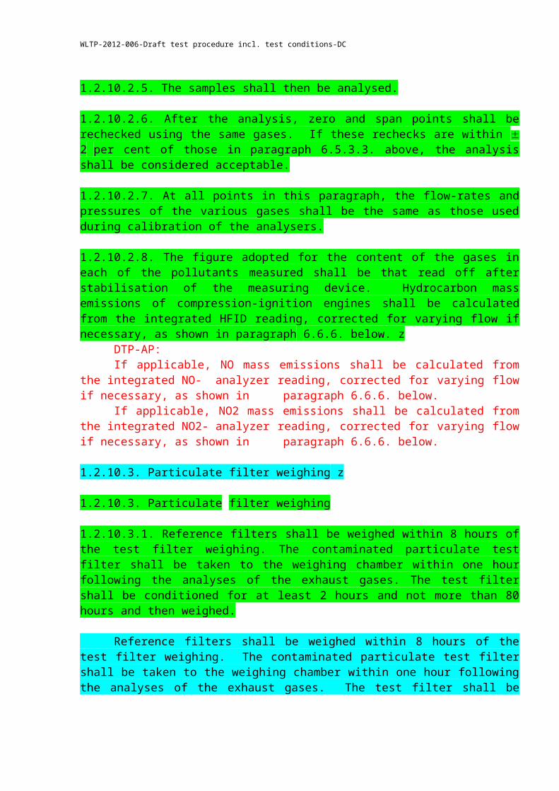
1.2.10.2.5. The samples shall then be analysed.
1.2.10.2.6. After the analysis, zero and span points shall be rechecked using the same gases. If these rechecks are within 2 per cent of those in paragraph 6.5.3.3. above, the analysis shall be considered acceptable.
1.2.10.2.7. At all points in this paragraph, the flow-rates and pressures of the various gases shall be the same as those used during calibration of the analysers.
1.2.10.2.8. The figure adopted for the content of the gases in each of the pollutants measured shall be that read off after stabilisation of the measuring device. Hydrocarbon mass emissions of compression-ignition engines shall be calculated from the integrated HFID reading, corrected for varying flow if necessary, as shown in paragraph 6.6.6. below. z
DTP-AP:
WLTP-2012-006-Draft test procedure incl. test conditions-DC
If applicable, NO mass emissions shall be calculated from the integrated NO-analyzer reading, corrected for varying flow if necessary, as shown in paragraph 6.6.6. below.If applicable, NO2 mass emissions shall be calculated from the integrated NO2-analyzer reading, corrected for varying flow if necessary, as shown in paragraph 6.6.6. below.
1.2.10.3. Particulate filter weighing z
1.2.10.3. Particulate filter weighing
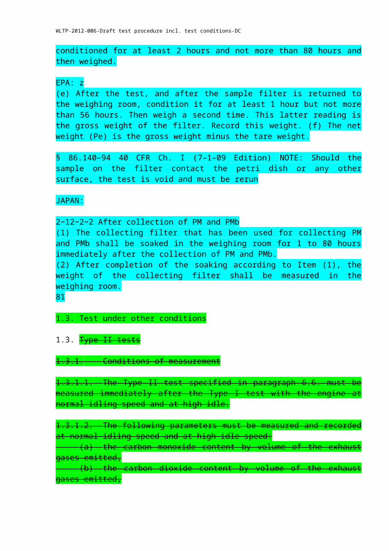
1.2.10.3.1. Reference filters shall be weighed within 8 hours of the test filter weighing. The contaminated particulate test filter shall be taken to the weighing chamber within one hour following the analyses of the exhaust gases. The test filter shall be conditioned for at least 2 hours and not more than 80 hours and then weighed.
Reference filters shall be weighed within 8 hours of the test filter weighing. The contaminated particulate test filter shall be taken to the weighing chamber within one hour following the analyses of the exhaust gases. The test filter shall be conditioned for at least 2 hours and not more than 80 hours and then weighed.
EPA: z(e) After the test, and after the sample filter is returned to the weighing room, condition it for at least 1 hour but not more than 56 hours. Then weigh a second time. This latter reading is the gross weight of the filter. Record this weight. (f) The net weight (Pe) is the gross weight minus the tare weight.
§ 86.140–94 40 CFR Ch. I (7–1–09 Edition) NOTE: Should the sample on the filter contact the petri dish or any other surface, the test is void and must be rerun
JAPAN:
2−12−2−2 After collection of PM and PMb(1) The collecting filter that has been used for collecting PM and PMb shall be soaked in the weighing room for 1 to 80 hours immediately after the collection of PM and PMb.(2) After completion of the soaking according to Item (1), the weight of the collecting filter shall be measured in the weighing room.81
1.3. Test under other conditions
1.3. Type II tests
1.3.1. Conditions of measurement
1.3.1.1. The Type II test specified in paragraph 6.6. must be measured immediately after the Type I test with the engine at normal idling speed and at high idle.
WLTP-2012-006-Draft test procedure incl. test conditions-DC
1.3.1.2. The following parameters must be measured and recorded at normal idling speed and at high idle speed: (a) the carbon monoxide content by volume of the exhaust gases emitted, (b) the carbon dioxide content by volume of the exhaust gases emitted, (c) the engine speed during the test, including any tolerances, (d) the engine oil temperature at the time of the test.
1.3.2. Sampling of exhaust gases
1.3.2.1. The exhaust outlets shall be provided with an air-tight extension, so that the sample probe used to collect exhaust gases may be inserted into the exhaust outlet at least 60 cm, without increasing the back pressure of more than 125 mm H20, and without disturbance of the vehicle running. The shape of this extension shall however be chosen in order to avoid, at the location of the sample probe, any appreciable dilution of exhaust gases in the air. Where a vehicle is equipped with an exhaust system having multiple outlets, either these shall be joined to a common pipe or the content of carbon monoxide must be collected from each of them, the result of the measurement being reached from the arithmetical average of these contents.
1.3.2.2. The concentrations in CO (CCO) and CO2 (CCO2 ) shall be determined from the measuring instrument readings or recordings, by use of appropriate calibration curves. The results have to be corrected according to paragraph 8.2.
WLTP-2012-006-Draft test procedure incl. test conditions-DC
z
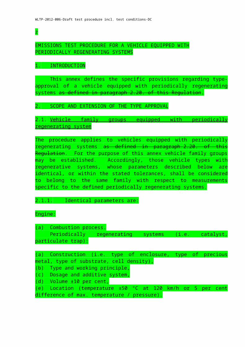
EMISSIONS TEST PROCEDURE FOR A VEHICLE EQUIPPED WITHPERIODICALLY REGENERATING SYSTEMS
1. INTRODUCTION
This annex defines the specific provisions regarding type-approval of a vehicle equipped with periodically regenerating systems as defined in paragraph 2.20. of this Regulation.
2. SCOPE AND EXTENSION OF THE TYPE APPROVAL
2.1. Vehicle family groups equipped with periodically regenerating system
The procedure applies to vehicles equipped with periodically regenerating systems as defined in paragraph 2.20. of this Regulation. For the purpose of this annex vehicle family groups may be established. Accordingly, those vehicle types with regenerative systems, whose parameters described below are identical, or within the stated tolerances, shall be considered to belong to the same family with respect to measurements specific to the defined periodically regenerating systems.
2.1.1. Identical parameters are:
Engine:
(a) Combustion process. Periodically regenerating systems (i.e. catalyst, particulate trap):
(a) Construction (i.e. type of enclosure, type of precious metal, type of substrate, cell density),(b) Type and working principle,(c) Dosage and additive system,(d) Volume ±10 per cent,(e) Location (temperature ±50 °C at 120 km/h or 5 per cent difference of max. temperature / pressure).
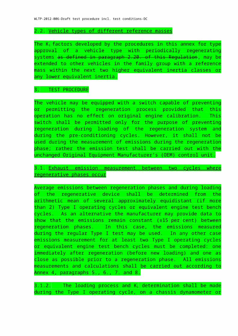
2.2. Vehicle types of different reference masses
The Ki factors developed by the procedures in this annex for type approval of a vehicle type with periodically regenerating systems as defined in paragraph 2.20. of this Regulation, may be extended to other vehicles in the family group with a reference mass within the next two higher equivalent inertia classes or any lower equivalent inertia.
3. TEST PROCEDURE
The vehicle may be equipped with a switch capable of preventing or permitting the regeneration process provided that this operation has no effect on original engine calibration. This switch shall be permitted only for the purpose of preventing regeneration during loading of the regeneration system and during the pre-conditioning cycles. However, it shall not be used during
WLTP-2012-006-Draft test procedure incl. test conditions-DC
the measurement of emissions during the regeneration phase; rather the emission test shall be carried out with the unchanged Original Equipment Manufacturer's (OEM) control unit.
3.1. Exhaust emission measurement between two cycles where regenerative phases occur
Average emissions between regeneration phases and during loading of the regenerative device shall be determined from the arithmetic mean of several approximately equidistant (if more than 2) Type I operating cycles or equivalent engine test bench cycles. As an alternative the manufacturer may provide data to show that the emissions remain constant (±15 per cent) between regeneration phases. In this case, the emissions measured during the regular Type I test may be used. In any other case emissions measurement for at least two Type I operating cycles or equivalent engine test bench cycles must be completed: one immediately after regeneration (before new loading) and one as close as possible prior to a regeneration phase. All emissions measurements and calculations shall be carried out according to Annex 4, paragraphs 5., 6., 7. and 8.
3.1.2. The loading process and Ki determination shall be made during the Type I operating cycle, on a chassis dynamometer or on an engine test bench using an equivalent test cycle. These cycles may be run continuously (i.e. without the need to switch the engine off between cycles). After any number of completed cycles, the vehicle may be removed from the chassis dynamometer, and the test continued at a later time.
3.1.3. The number of cycles (D) between two cycles where regeneration phases occur, the number of cycles over which emissions measurements are made (n), and each emissions measurement (M’sij) shall be reported in Annex 1, items 4.2.11.2.1.10.1. to 4.2.11.2.1.10.4. or 4.2.11.2.5.4.1. to 4.2.11.2.5.4.4. as applicable.
3.2. Measurement of emissions during regeneration
3.2.1. Preparation of the vehicle, if required, for the emissions test during a regeneration phase, may be completed using the preparation cycles in paragraph 5.3. of Annex 4 or equivalent engine test bench cycles, depending on the loading procedure chosen in paragraph 3.1.2. above.
3.2.2. The test and vehicle conditions for the Type I test described in Annex 4 apply before the first valid emission test is carried out.
3.2.3. Regeneration must not occur during the preparation of the vehicle. This may be ensured by one of the following methods:
3.2.3.1. A "dummy" regenerating system or partial system may be fitted for the pre-conditioning cycles.
3.2.3.2. Any other method agreed between the manufacturer and the type approval authority.
3.2.4. A cold-start exhaust emission test including a regeneration process shall be performed according to the Type I operating cycle, or equivalent engine test bench cycle. If the emissions tests between two cycles where regeneration phases occur are carried out on an engine test
WLTP-2012-006-Draft test procedure incl. test conditions-DC
bench, the emissions test including a regeneration phase shall also be carried out on an engine test bench.
3.2.5. If the regeneration process requires more than one operating cycle, subsequent test cycle(s) shall be driven immediately, without switching the engine off, until complete regeneration has been achieved (each cycle shall be completed). The time necessary to set up a new test should be as short as possible (e.g. particular matter filter change). The engine must be switched off during this period.
3.2.6. The emission values during regeneration (Mri) shall be calculated according to Annex 4, paragraph 8. The number of operating cycles (d) measured for complete regeneration shall be recorded.
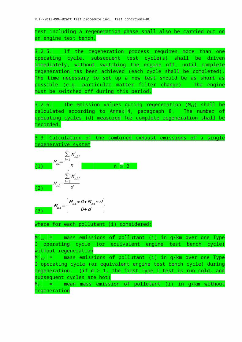
3.3. Calculation of the combined exhaust emissions of a single regenerative system
(1) M si=
∑j=1
n
M sij'
n n 2
(2) M ri=
∑j=1
d
M rij'
d
(3) M pi={M si∗D+M ri∗d
D+d }where for each pollutant (i) considered:
M’sij = mass emissions of pollutant (i) in g/km over one Type I operating cycle (or equivalent engine test bench cycle) without regenerationM’rij = mass emissions of pollutant (i) in g/km over one Type I operating cycle (or equivalent engine test bench cycle) during regeneration. (if d > 1, the first Type I test is run cold, and subsequent cycles are hot)Msi = mean mass emission of pollutant (i) in g/km without regeneration
Mri = mean mass emission of pollutant (i) in g/km during regenerationMpi = mean mass emission of pollutant (i) in g/km
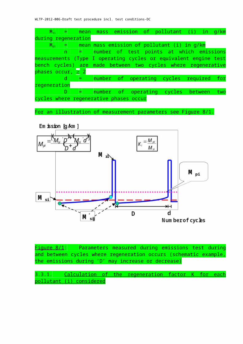
n = number of test points at which emissions measurements (Type I operating cycles or equivalent engine test bench cycles) are made between two cycles where regenerative phases occur, 2
d = number of operating cycles required for regenerationD = number of operating cycles between two cycles where regenerative
phases occur
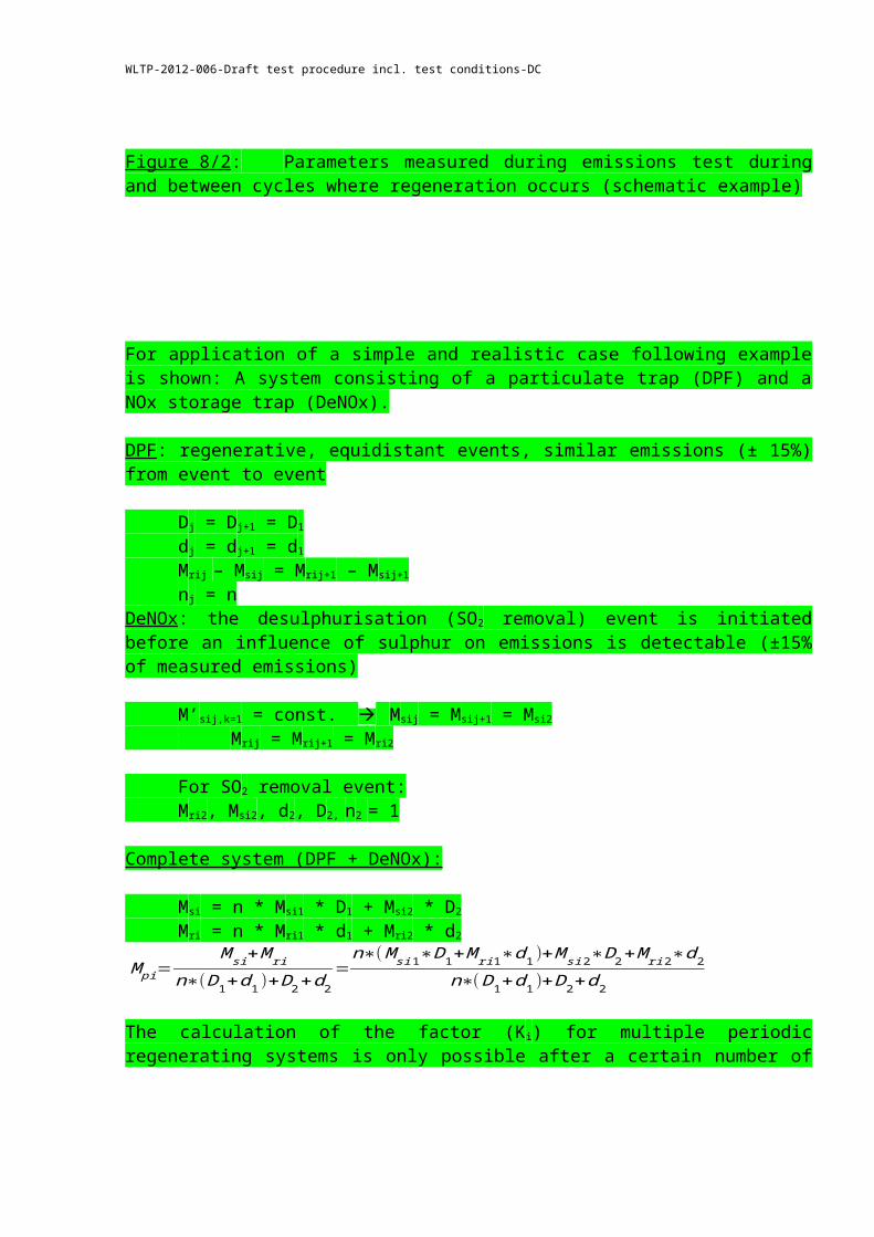
For an illustration of measurement parameters see Figure 8/1.
WLTP-2012-006-Draft test procedure incl. test conditions-DC
Figure 8/1: Parameters measured during emissions test during and between cycles where regeneration occurs (schematic example, the emissions during ‘D’ may increase or decrease)
3.3.1. Calculation of the regeneration factor K for each pollutant (i) considered
The manufacturer may elect to determine either additive or multiplicative factors,
For multiplicative factors; Ki = Mpi / Msi
For additive factors; Ki = Mpi - Msi
Msi, Mpi and Ki results, and the manufacturer’s choice of type of factor shall be recorded in the test report delivered by the technical service.
Ki may be determined following the completion of a single sequence.
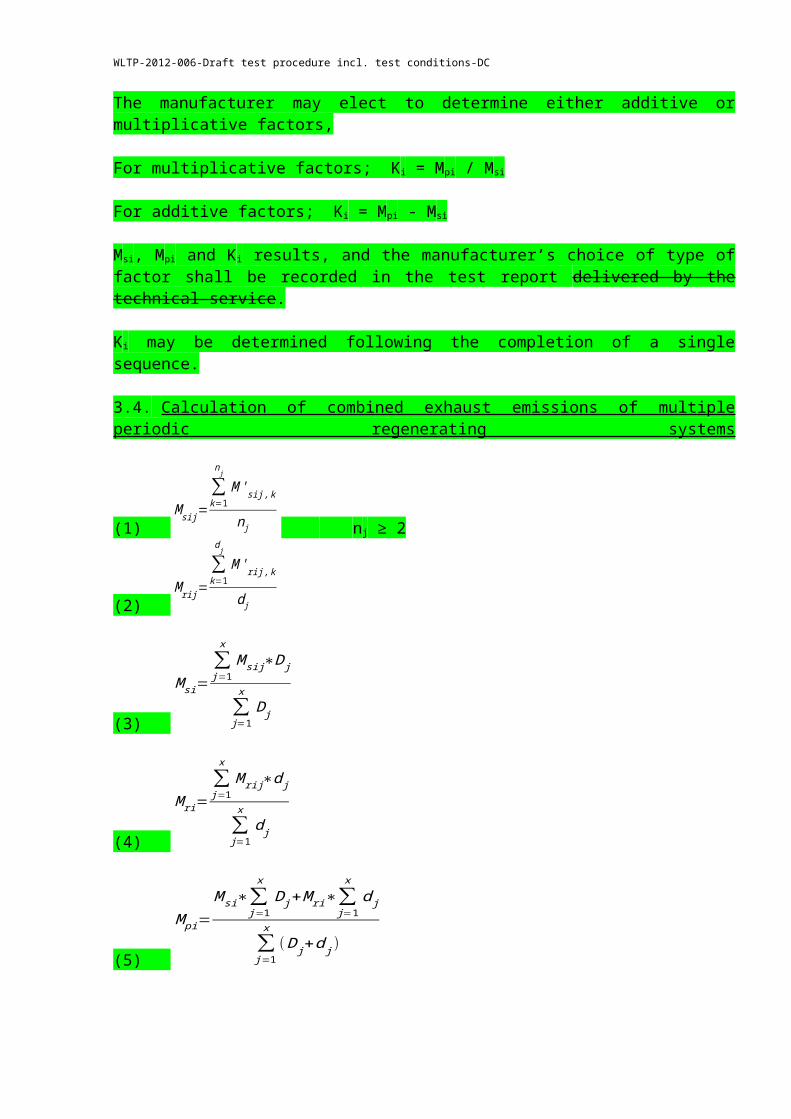
3.4. Calculation of combined exhaust emissions of multiple periodic regenerating systems
(1) M sij=
∑k=1
n j
M ' sij , k
n j nj ≥ 2
(2) M rij=
∑k=1
d j
M 'rij , k
d j
WLTP-2012-006-Draft test procedure incl. test conditions-DC
(3)
M si=∑j=1
x
M sij∗D j
∑j=1
x
D j
(4)
M ri=∑j=1
x
M rij∗d j
∑j=1
x
d j
(5)
M pi=M si∗∑
j=1
x
D j+M ri∗∑j=1
x
d j
∑j=1
x
( D j+d j)
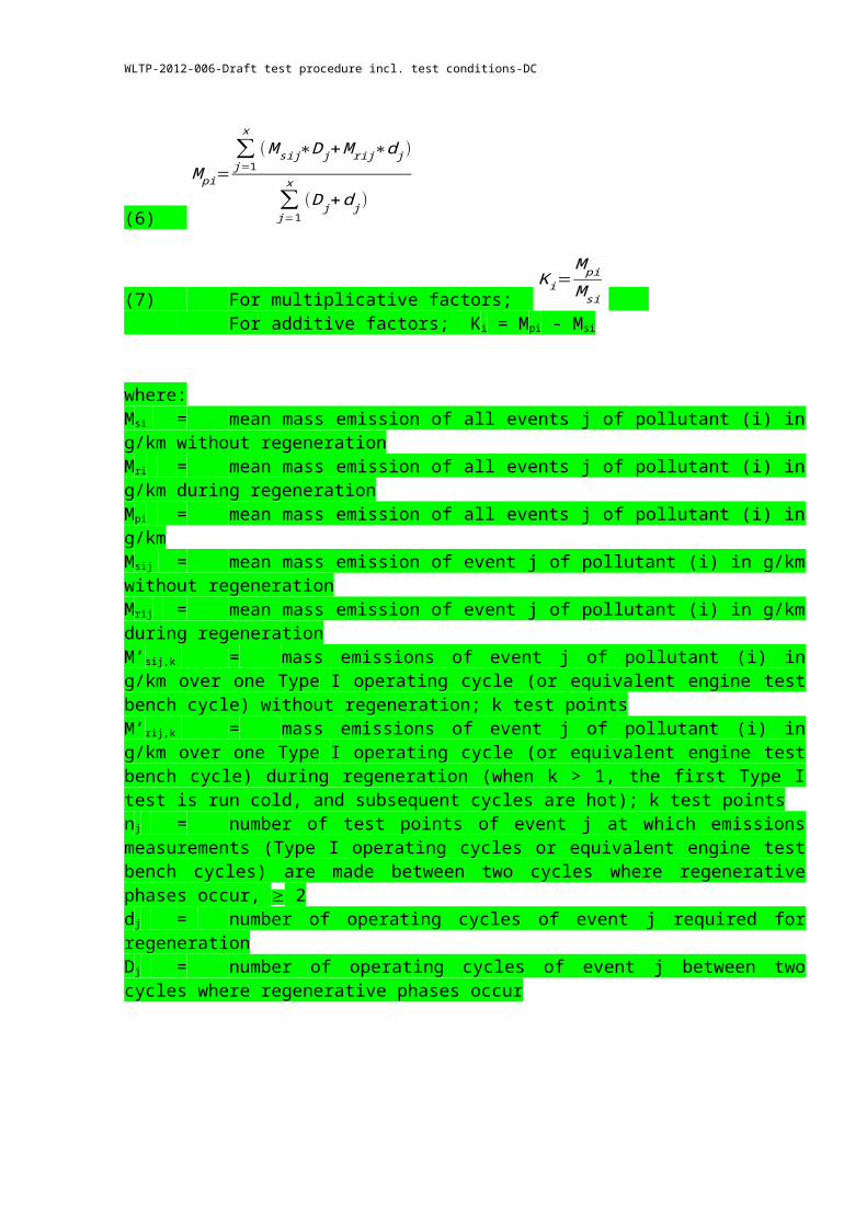
(6)
M pi=∑j=1
x
( M sij∗D j+M rij∗d j)
∑j=1
x
( D j+d j )
(7) For multiplicative factors; K i=
M pi
M si For additive factors; Ki = Mpi - Msi
where: Msi = mean mass emission of all events j of pollutant (i) in g/km without regenerationMri = mean mass emission of all events j of pollutant (i) in g/km during regenerationMpi = mean mass emission of all events j of pollutant (i) in g/kmMsij = mean mass emission of event j of pollutant (i) in g/km without regenerationMrij = mean mass emission of event j of pollutant (i) in g/km during regenerationM’sij,k = mass emissions of event j of pollutant (i) in g/km over one Type I operating cycle (or equivalent engine test bench cycle) without regeneration; k test pointsM’rij,k = mass emissions of event j of pollutant (i) in g/km over one Type I operating cycle (or equivalent engine test bench cycle) during regeneration (when k > 1, the first Type I test is run cold, and subsequent cycles are hot); k test pointsnj = number of test points of event j at which emissions measurements (Type I operating cycles or equivalent engine test bench cycles) are made between two cycles where regenerative phases occur, 2dj = number of operating cycles of event j required for regenerationDj = number of operating cycles of event j between two cycles where regenerative phases occur
Number of cycles
E m is si o n s
[g / k m ]
D (1) d (1)
d (x)
D (2) d (2) D (3) d (3) D (x)
M pi
M si
M ri(1) M ri(2) M ri(3)
M ri(x)
M si(1)M si(2)
M si(3)M si(x)
M si(1)
A B
WLTP-2012-006-Draft test procedure incl. test conditions-DC
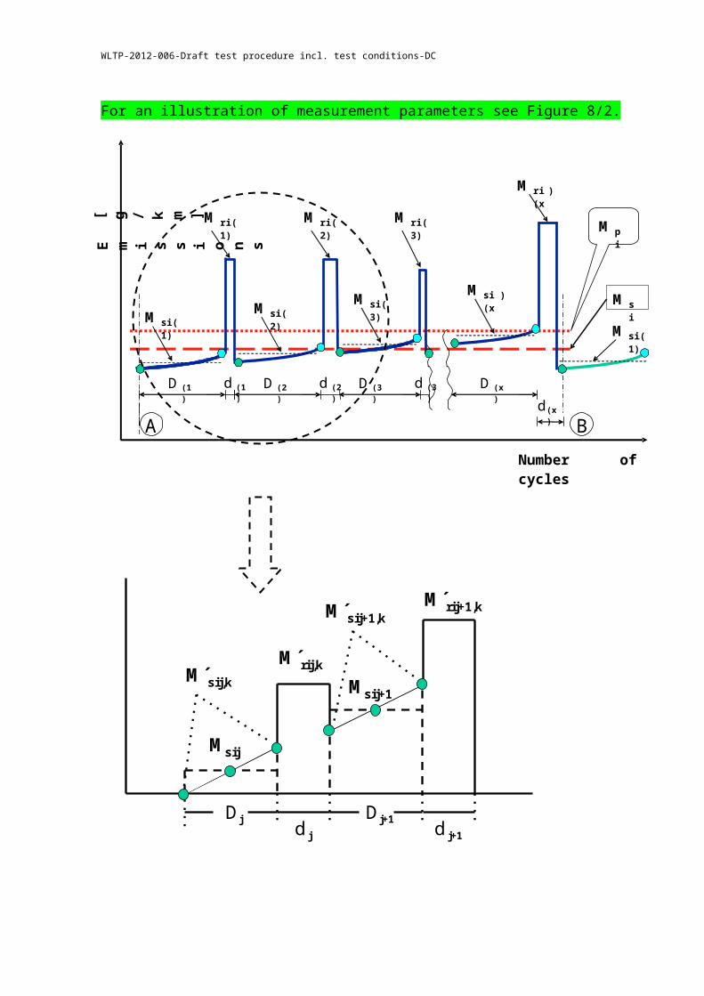
For an illustration of measurement parameters see Figure 8/2.
Figure 8/2: Parameters measured during emissions test during and between cycles where regeneration occurs (schematic example)
Dj d j
Dj+1 d j+1
M´sij,k
M´sij+1,k
M´rij,k
M´rij+1,k
Msij
Msij+1
WLTP-2012-006-Draft test procedure incl. test conditions-DC
For application of a simple and realistic case following example is shown: A system consisting of a particulate trap (DPF) and a NOx storage trap (DeNOx).
DPF: regenerative, equidistant events, similar emissions (± 15%) from event to event
Dj = Dj+1 = D1
dj = dj+1 = d1
Mrij – Msij = Mrij+1 – Msij+1
nj = nDeNOx: the desulphurisation (SO2 removal) event is initiated before an influence of sulphur on emissions is detectable (±15% of measured emissions)
M’sij,k=1 = const. Msij = Msij+1 = Msi2
Mrij = Mrij+1 = Mri2
For SO2 removal event:Mri2, Msi2, d2, D2, n2 = 1
Complete system (DPF + DeNOx):
Msi = n * Msi1 * D1 + Msi2 * D2
Mri = n * Mri1 * d1 + Mri2 * d2
M pi=M si+M ri
n∗( D1+d1 )+D2+d2=
n∗( M si1∗D1+M ri 1∗d1)+M si2∗D2+M ri 2∗d2
n∗( D1+d1)+D2+d2
The calculation of the factor (Ki) for multiple periodic regenerating systems is only possible after a certain number of regeneration phases for each system. After performing the complete procedure (A to B, see Figure 8/2), the original starting conditions A should be reached again.
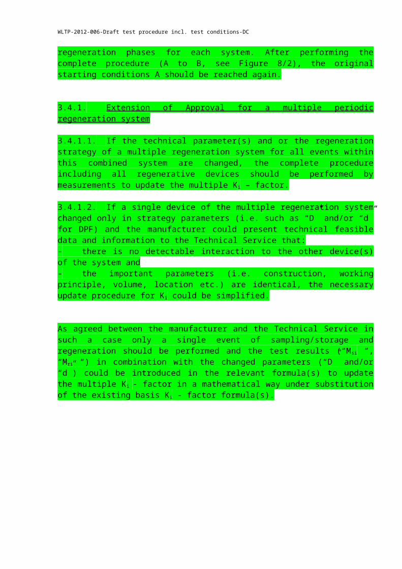
3.4.1. Extension of Approval for a multiple periodic regeneration system
3.4.1.1. If the technical parameter(s) and or the regeneration strategy of a multiple regeneration system for all events within this combined system are changed, the complete procedure including all regenerative devices should be performed by measurements to update the multiple Ki – factor.
3.4.1.2. If a single device of the multiple regeneration system changed only in strategy parameters (i.e. such as “D” and/or “d” for DPF) and the manufacturer could present technical feasible data and information to the Technical Service that:- there is no detectable interaction to the other device(s) of the system and- the important parameters (i.e. construction, working principle, volume, location etc.) are identical, the necessary update procedure for Ki could be simplified.

WLTP-2012-006-Draft test procedure incl. test conditions-DC
As agreed between the manufacturer and the Technical Service in such a case only a single event of sampling/storage and regeneration should be performed and the test results (“Msi “, “Mri “) in combination with the changed parameters (“D” and/or “d”) could be introduced in the relevant formula(s) to update the multiple Ki - factor in a mathematical way under substitution of the existing basis Ki - factor formula(s).
WLTP-2012-006-Draft test procedure incl. test conditions-DC
Annex 8 z
EMISSIONS TEST PROCEDURE AND CALCULATION FOR ELECTRIFIED VEHICLES
1. INTRODUCTION
1.1. This annex defines the specific provisions regarding type-approval of a hybrid electric vehicle (HEV) as defined in paragraph 2.21.2. of this Regulation.
1.2. As a general principle, for the tests of Type I, II, III, IV, V, VI and OBD, hybrid electric vehicles shall be tested according to Annex 4, 5, 6, 7, 9, 8 and 11 respectively, unless modified by this annex.
1.3. For the Type I test only, OVC vehicles (as categorized in paragraph 2.) shall be tested according to condition A and to condition B. The test results under both conditions A and B and the weighted values shall be reported in the communication form.
1.4. The emissions test results shall comply with the limits under all specified test conditions of this Regulation.
2. CATEGORIES OF HYBRID ELECTRIC VEHICLES
Vehicle charging
Off-Vehicle Charging (1)(OVC)
Not Off-Vehicle Charging (2)(NOVC)
Operating mode switch Without With Without With
(1) also known as "externally chargeable"(2) also known as "not externally chargeable"
3. TYPE I TEST METHODS
3.1. EXTERNALLY CHARGEABLE (OVC HEV) WITHOUT AN OPERATING MODE SWITCH
3.1.1. Two tests shall be performed under the following conditions:
Condition A: test shall be carried out with a fully charged electrical energy/power storage device.
Condition B: test shall be carried out with an electrical energy/power storage device in minimum state of charge (maximum discharge of capacity).
The profile of the state of charge (SOC) of the electrical energy/power storage device during different stages of the Type I test is given in Appendix 1.
WLTP-2012-006-Draft test procedure incl. test conditions-DC
3.1.2. Condition A
3.1.2.1. The procedure shall start with the discharge of the electrical energy/power storage device of the vehicle while driving (on the test track, on a chassis dynamometer, etc.):
- at a steady speed of 50 km/h until the fuel consuming engine of the HEV starts up,
- or, if a vehicle cannot reach a steady speed of 50 km/h without starting up the fuel consuming engine, the speed shall be reduced until the vehicle can run a lower steady speed where the fuel consuming engine does not start up for a defined time/distance (to be specified between technical service and manufacturer),
- or with manufacturer’s recommendation.
The fuel consuming engine shall be stopped within 10 seconds of it being automatically started.
3.1.2.2. Conditioning of vehicle
3.1.2.2.1. For compression-ignition engined vehicles the Part Two cycle described in Appendix 1 of Annex 4 shall be used. Three consecutive cycles shall be driven according to paragraph 3.1.2.5.3. below.
3.1.2.2.2. Vehicles fitted with positive-ignition engines shall be preconditioned with one Part One and two Part Two driving cycles according to paragraph 3.1.2.5.3. below.
3.1.2.3. After this preconditioning, and before testing, the vehicle shall be kept in a room in which the temperature remains relatively constant between 293 and 303 K (20 °C and 30 °C). This conditioning shall be carried out for at least six hours and continue until the engine oil temperature and coolant, if any, are within ± 2 K of the temperature of the room, and the electrical energy/power storage device is fully charged as a result of the charging prescribed in paragraph 3.1.2.4. below.
3.1.2.4. During soak, the electrical energy/power storage device shall be charged:
(a) with the on board charger if fitted, or
(b) with an external charger recommended by the manufacturer, using the normal overnight charging procedure.
This procedure excludes all types of special charges that could be automatically or manually initiated like, for instance, the equalization charges or the servicing charges.
The manufacturer shall declare that during the test, a special charge procedure has not occurred.
3.1.2.5. Test procedure
WLTP-2012-006-Draft test procedure incl. test conditions-DC
3.1.2.5.1. The vehicle shall be started up by the means provided for normal use to the driver. The first cycle starts on the initiation of the vehicle start-up procedure.
3.1.2.5.2. Sampling shall begin (BS) before or at the initiation of the vehicle start up procedure and end on conclusion of the final idling period in the extra-urban cycle (Part Two, end of sampling (ES)).
3.1.2.5.3. The vehicle shall be driven according to Annex 4, or in case of special gear shifting strategy according to the manufacturer's instructions, as incorporated in the drivers' handbook of production vehicles and indicated by a technical gear shift instrument (for drivers information). For these vehicles the gear shifting points prescribed in Annex 4, Appendix 1 are not applied. For the pattern of the operating curve the description according to paragraph 2.3.3. in Annex 4 shall apply.
3.1.2.5.4. The exhaust gases shall be analyzed according to Annex 4.
3.1.2.6. The test results shall be compared to the limits prescribed in paragraph 5.3.1.4. of this Regulation and the average emission of each pollutant for Condition A shall be calculated (M1i).
3.1.3. Condition B
3.1.3.1. Conditioning of vehicle
3.1.3.1.1. For compression-ignition engined vehicles the Part Two cycle described in Appendix 1 of Annex 4 shall be used. Three consecutive cycles shall be driven according to paragraph 3.1.3.4.3. below.
3.1.3.1.2. Vehicles fitted with positive-ignition engines shall be preconditioned with one Part One and two Part Two driving cycles according to paragraph 3.1.3.4.3. below.
3.1.3.2. The electrical energy/power storage device of the vehicle shall be discharged while driving (on the test track, on a chassis dynamometer, etc.):
- at a steady speed of 50 km/h until the fuel consuming engine of the HEV starts up,
- or if a vehicle cannot reach a steady speed of 50 km/h without starting up the fuel consuming engine, the speed shall be reduced until the vehicle can run a lower steady speed where the fuel consuming engine just does not start up for a defined time/distance (to be specified between technical service and manufacturer),
- or with manufacturer’s recommendation.
The fuel consuming engine shall be stopped within 10 seconds of it being automatically started.
WLTP-2012-006-Draft test procedure incl. test conditions-DC
3.1.3.3. After this preconditioning, and before testing, the vehicle shall be kept in a room in which the temperature remains relatively constant between 293 and 303 K (20 °C and 30 °C). This conditioning shall be carried out for at least six hours and continue until the engine oil temperature and coolant, if any, are within ± 2 K of the temperature of the room.
3.1.3.4. Test procedure
3.1.3.4.1. The vehicle shall be started up by the means provided for normal use to the driver. The first cycle starts on the initiation of the vehicle start-up procedure.
3.1.3.4.2. Sampling shall begin (BS) before or at the initiation of the vehicle start up procedure and end on conclusion of the final idling period in the extra-urban cycle (Part Two, end of sampling (ES)).
3.1.3.4.3. The vehicle shall be driven according to Annex 4, or in case of special gear shifting strategy according to the manufacturer's instructions, as incorporated in the drivers' handbook of production vehicles and indicated by a technical gear shift instrument (for drivers information). For these vehicles the gear shifting points prescribed in Annex 4, Appendix 1 are not applied. For the pattern of the operating curve the description according to paragraph 2.3.3. in Annex 4 shall apply.
3.1.3.4.4. The exhaust gases shall be analyzed according to Annex 4.
3.1.3.5. The test results shall be compared to the limits prescribed in paragraph 5.3.1.4. of this Regulation and the average emission of each pollutant for Condition B shall be calculated (M2i).
3.1.4. Test results
3.1.4.1. For communication, the weighted values shall be calculated as below:
Mi = ( De M1i + Dav M2i ) / ( De + Dav )
Where:
Mi = mass emission of the pollutant i in grams per kilometre.M1i = average mass emission of the pollutant i in grams per kilometre with a
fully charged electrical energy/power storage device calculated in paragraph 3.1.2.6.M2i = average mass emission of the pollutant i in grams per kilometre with an
electrical energy/power storage device in minimum state of charge (maximum discharge of capacity) calculated in paragraph 3.1.3.5.
De = vehicle electric range, according to the procedure described in Regulation No. 101, Annex 7, where the manufacturer must provide the means for performing the measurement with the vehicle running in pure electric mode.
Dav = 25 km (average distance between two battery recharges)
3.2. EXTERNALLY CHARGEABLE (OVC HEV) WITH AN OPERATING MODE SWITCH
WLTP-2012-006-Draft test procedure incl. test conditions-DC
3.2.1. Two tests shall be performed under the following conditions:
3.2.1.1. Condition A: test shall be carried out with a fully charged electrical energy/power storage device.
3.2.1.2. Condition B: test shall be carried out with an electrical energy/power storage device in minimum state of charge (maximum discharge of capacity)3.2.1.3. The operating mode switch shall be positioned according the table below:
Hybrid- modes
-Pure electric
-Hybrid
Switch in position
-Pure fuel consuming-Hybrid
Switch in position
-Pure electric-Pure fuel consuming-Hybrid
Switch in position
-Hybrid mode n (1)......-Hybrid mode m (1)
Switch in positionBatterystateof chargeCondition AFully charged
Hybrid Hybrid Hybrid Most electric hybrid mode (2)
Condition BMin. state of charge
Hybrid Fuel consuming Fuel consuming Most fuel consuming mode (3)
(1) For instance: sport, economic, urban, extra-urban position ...(2) Most electric hybrid mode:
The hybrid mode which can be proven to have the highest electricity consumption of all selectable hybrid modes when tested in accordance with condition A of paragraph 4. of Annex 10 to Regulation No. 101, to be established based on information provided by the manufacturer and in agreement with the technical service.(3) Most fuel consuming mode:
The hybrid mode which can be proven to have the highest fuel consumption of all selectable hybrid modes when tested in accordance with condition B of paragraph 4. of Annex 10 to Regulation No. 101, to be established based on information provided by the manufacturer and in agreement with the technical service.
3.2.2. Condition A
3.2.2.1. If the pure electric range of the vehicle is higher than one complete cycle, on the request of the manufacturer, the Type I test may be carried out in pure electric mode. In this case, engine preconditioning prescribed in paragraph 3.2.2.3.1. or 3.2.2.3.2. can be omitted.
3.2.2.2. The procedure shall start with the discharge of the electrical energy/power storage device of the vehicle while driving with the switch in pure electric position (on the test track, on a chassis dynamometer, etc.) at a steady speed of 70 per cent ± 5 per cent of the maximum thirty minutes speed of the vehicle (determined according to Regulation No. 101).
Stopping the discharge occurs:
WLTP-2012-006-Draft test procedure incl. test conditions-DC
- when the vehicle is not able to run at 65 per cent of the maximum thirty minutes speed; or
- when an indication to stop the vehicle is given to the driver by the standard on-board instrumentation, or
- after covering the distance of 100 km.
If the vehicle is not equipped with a pure electric mode, the electrical energy/power storage device discharge shall be achieved by driving the vehicle (on the test track, on a chassis dynamometer, etc.):
- at a steady speed of 50 km/h until the fuel consuming engine of the HEV starts up, or
- if a vehicle cannot reach a steady speed of 50 km/h without starting up the fuel consuming engine, the speed shall be reduced until the vehicle can run a lower steady speed where the fuel consuming engine does not start up for a defined time/distance (to be specified between technical service and manufacturer), or
- with manufacturer’s recommendation.
The fuel consuming engine shall be stopped within 10 seconds of it being automatically started.
3.2.2.3. Conditioning of vehicle
3.2.2.3.1. For compression-ignition engined vehicles the Part Two cycle described in Appendix 1 to the Annex 4 shall be used. Three consecutive cycles shall be driven according to paragraph 3.2.2.6.3. below.
3.2.2.3.2. Vehicles fitted with positive-ignition engines shall be preconditioned with one Part One and two Part Two driving cycles according to paragraph 3.2.2.6.3. below.
3.2.2.4. After this preconditioning, and before testing, the vehicle shall be kept in a room in which the temperature remains relatively constant between 293 and 303 K (20 °C and 30 °C). This conditioning shall be carried out for at least six hours and continue until the engine oil temperature and coolant, if any, are within ± 2 K of the temperature of the room, and the electrical energy/power storage device is fully charged as a result of the charging prescribed in paragraph 3.2.2.5.
3.2.2.5. During soak, the electrical energy/power storage device shall be charged:
(a) with the on board charger if fitted, or
(b) with an external charger recommended by the manufacturer, using the normal overnight charging procedure.
This procedure excludes all types of special charges that could be automatically or manually initiated like, for instance, the equalisation charges or the servicing charges.
WLTP-2012-006-Draft test procedure incl. test conditions-DC
The manufacturer shall declare that during the test, a special charge procedure has not occurred.
3.2.2.6. Test procedure
3.2.2.6.1. The vehicle shall be started up by the means provided for normal use to the driver. The first cycle starts on the initiation of the vehicle start-up procedure.
3.2.2.6.2. Sampling shall begin (BS) before or at the initiation of the vehicle start up procedure and end on conclusion of the final idling period in the extra-urban cycle (Part Two, end of sampling (ES)).
3.2.2.6.3. The vehicle shall be driven according to Annex 4, or in case of special gear shifting strategy according to the manufacturer's instructions, as incorporated in the drivers' handbook of production vehicles and indicated by a technical gear shift instrument (for drivers information). For these vehicles the gear shifting points prescribed in Annex 4, Appendix 1 are not applied. For the pattern of the operating curve the description according to paragraph 2.3.3. in Annex 4 shall apply.
3.2.2.6.4. The exhaust gases shall be analysed according to Annex 4.
3.2.2.7. The test results shall be compared to the limits prescribed in paragraph 5.3.1.4. of this Regulation and the average emission of each pollutant for Condition A shall be calculated (M1i).
3.2.3. Condition B
3.2.3.1. Conditioning of vehicle
3.2.3.1.1. For compression-ignition engined vehicles the Part Two cycle described in Appendix 1 to the Annex 4 shall be used. Three consecutive cycles shall be driven according to paragraph 3.2.3.4.3. below.
3.2.3.1.2. Vehicles fitted with positive-ignition engines shall be preconditioned with one Part One and two Part Two driving cycles according to paragraph 3.2.3.4.3. below.
3.2.3.2. The electrical energy/power storage device of the vehicle shall be discharged according to paragraph 3.2.2.2.
3.2.3.3. After this preconditioning, and before testing, the vehicle shall be kept in a room in which the temperature remains relatively constant between 293 and 303 K (20 °C and 30 °C). This conditioning shall be carried out for at least six hours and continue until the engine oil temperature and coolant, if any, are within ± 2 K of the temperature of the room.
3.2.3.4. Test procedure
3.2.3.4.1. The vehicle shall be started up by the means provided for normal use to the driver. The first cycle starts on the initiation of the vehicle start-up procedure.
WLTP-2012-006-Draft test procedure incl. test conditions-DC
3.2.3.4.2. Sampling shall begin (BS) before or at the initiation of the vehicle start up procedure
and end on conclusion of the final idling period in the extra-urban cycle (Part Two, end of sampling (ES)).
3.2.3.4.3. The vehicle shall be driven according to Annex 4, or in case of special gear shifting strategy according to the manufacturer's instructions, as incorporated in the drivers' handbook of production vehicles and indicated by a technical gear shift instrument (for drivers information). For these vehicles the gear shifting points prescribed in Annex 4, Appendix 1 are not applied. For the pattern of the operating curve the description according to paragraph 2.3.3. in Annex 4 shall apply.
3.2.3.4.4. The exhaust gases shall be analysed according to Annex 4.
3.2.3.5. The test results shall be compared to the limits prescribed in paragraph 5.3.1.4. of this Regulation and the average emission of each pollutant for Condition B shall be calculated (M2i).
3.2.4. Test results
3.2.4.1. For communication, the weighted values shall be calculated as below:
Mi = ( De M1i + Dav M2i ) / ( De + Dav )
Where :Mi = mass emission of the pollutant i in grams per kilometre M1i = average mass emission of the pollutant i in grams per kilometre with a fully charged electrical energy/power storage device calculated in paragraph 3.2.2.7.M2i = average mass emission of the pollutant i in grams per kilometre with an electrical energy/power storage device in minimum state of charge (maximum discharge of capacity) calculated in paragraph 3.2.3.5.De = vehicle electric range with the switch in pure electric position, according to the procedure described in Regulation No. 101, Annex 7. If there is not a pure electric position, the manufacturer must provide the means for performing the measurement with the vehicle running in pure electric mode.Dav = 25 km (average distance between two battery recharge).
3.3. NOT EXTERNALLY CHARGEABLE (NOTOVC HEV) WITHOUT AN OPERATING MODE SWITCH
3.3.1. These vehicles shall be tested according to Annex 4.
3.3.2. For preconditioning, at least two consecutive complete driving cycles (one Part One and one Part Two) are carried out without soak.
3.3.3. The vehicle shall be driven according to Annex 4, or in case of special gear shifting strategy according to the manufacturer's instructions, as incorporated in the drivers' handbook of
WLTP-2012-006-Draft test procedure incl. test conditions-DC
production vehicles and indicated by a technical gear shift instrument (for drivers information). For these vehicles the gear shifting points prescribed in Annex 4, Appendix 1 are not applied. For the pattern of the operating curve the description according to paragraph 2.3.3. in Annex 4 shall apply.
3.4. NOT EXTERNALLY CHARGEABLE (NOTOVC HEV) WITH AN OPERATING MODE SWITCH
3.4.1. These vehicles are preconditioned and tested in hybrid mode according to Annex 4. If several hybrid modes are available, the test shall be carried out in the mode that is automatically set after turn on of the ignition key (normal mode). On the basis of information provided by the manufacturer, the Technical Service will make sure that the limit values are met in all hybrid modes.
3.4.2. For preconditioning, at least two consecutive complete driving cycles (one Part One and one Part Two) shall be carried out without soak.
3.4.3. The vehicle shall be driven according to Annex 4, or in case of special gear shifting strategy according to the manufacturer's instructions, as incorporated in the drivers' handbook of production vehicles and indicated by a technical gear shift instrument (for drivers information). For these vehicles the gear shifting points prescribed in Annex 4, Appendix 1 are not applied. For the pattern of the operating curve the description according to paragraph 2.3.3. in Annex 4 shall apply.
4. TYPE II TEST METHODS
4.1. The vehicles shall be tested according to Annex 5 with the fuel consuming engine running. The manufacturer shall provide a "service mode" that makes execution of this test possible.
If necessary, the special procedure provided for in paragraph 5.1.6. to the Regulation shall be used.
5. TYPE III TEST METHODS
5.1. The vehicles shall be tested according to Annex 6 with the fuel consuming engine running. The manufacturer shall provide a "service mode" that makes execution of this test possible.
5.2. The tests shall be carried out only for conditions 1 and 2 of the paragraph 3.2. of Annex 6. If for any reasons it is not possible to test on condition 2, alternatively another steady speed condition (with fuel consuming engine running under load) should be carried out.
6. TYPE IV TEST METHODS
6.1. The vehicles shall be tested according to Annex 7.
6.2. Before starting the test procedure (paragraph 5.1. of Annex 7), the vehicles shall be preconditioned as follows:
WLTP-2012-006-Draft test procedure incl. test conditions-DC
6.2.1. For OVC vehicles:
6.2.1.1. OVC vehicles without an operating mode switch: the procedure shall start with the discharge of the electrical energy/power storage device of the vehicle while driving (on the test track, on a chassis dynamometer, etc.):
- at a steady speed of 50 km/h until the fuel consuming engine of the HEV starts up, or
- if a vehicle cannot reach a steady speed of 50 km/h without starting up the fuel consuming engine, the speed shall be reduced until the vehicle can run a lower steady speed where the fuel consuming engine just does not start up for a defined time/distance (to be specified between technical service and manufacturer), or
- with manufacturer’s recommendation.
The fuel consuming engine shall be stopped within 10 seconds of it being automatically started.
6.2.1.2. OVC vehicles with an operating mode switch: the procedure shall start with the discharge of the electrical energy/power storage device of the vehicle while driving with the switch in pure electric position (on the test track, on a chassis dynamometer, etc.) at a steady speed of 70 per cent ± 5 per cent from the maximum thirty minutes speed of the vehicle.
Stopping the discharge occurs:
- when the vehicle is not able to run at 65 per cent of the maximum thirty minutes speed, or
- when an indication to stop the vehicle is given to the driver by the standard on-board instrumentation, or
- after covering the distance of 100 km.
If the vehicle is not equipped with a pure electric mode, the electrical energy/power storage device discharge shall be conducted with the vehicle driving (on the test track, on a chassis dynamometer, etc.):
- at a steady speed of 50 km/h until the fuel consuming engine of the HEV starts up, or
- if a vehicle cannot reach a steady speed of 50 km/h without starting up the fuel consuming engine, the speed shall be reduced until the vehicle can run a lower steady speed where the fuel consuming engine does not start up for a defined time/distance (to be specified between technical service and manufacturer), or
- with manufacturer’s recommendation.
WLTP-2012-006-Draft test procedure incl. test conditions-DC
The engine shall be stopped within 10 seconds of it being automatically started.
6.2.2. For NOVC vehicles:
6.2.2.1. NOVC vehicles without an operating mode switch: the procedure shall start with a preconditioning of at least two consecutive complete driving cycles (one Part One and one Part Two) without soak.
6.2.2.2. NOVC vehicles with an operating mode switch: the procedure shall start with a preconditioning of at least two consecutive complete driving cycles (one Part One and one Part Two) without soak, performed with the vehicle running in hybrid mode. If several hybrid modes are available, the test shall be carried out in the mode which is automatically set after turn on of the ignition key (normal mode).
6.3. The preconditioning drive and the dynamometer test shall be carried out according to paragraphs 5.2. and 5.4. of Annex 7:
6.3.1. For OVC vehicles: under the same conditions as specified by condition B of the Type I test (paragraphs 3.1.3. and 3.2.3.).
6.3.2. For NOVC vehicles: under the same conditions as in the Type I test.
7. TYPE V TEST METHODS
7.1. The vehicles shall be tested according to Annex 9.
7.2. For OVC vehicles:
It is allowed to charge the electrical energy/power storage device twice a day during mileage accumulation.
For OVC vehicles with an operating mode switch, mileage accumulation should be driven in the mode which is automatically set after turn on of the ignition key (normal mode).
During the mileage accumulation a change into another hybrid mode is allowed if necessary in order to continue the mileage accumulation after agreement of the technical service.
The measurements of emissions of pollutants shall be carried out under the same conditions as specified by condition B of the Type I test (paragraphs 3.1.3. and 3.2.3.).
7.3. For NOVC vehicles:
For NOVC vehicles with an operating mode switch, mileage accumulation shall be driven in the mode which is automatically set after turn on of the ignition key (normal mode).
The measurements of emissions of pollutants shall be carried out in the same conditions as in the Type I test.
8. TYPE VI TEST METHODS
8.1. The vehicles shall be tested according to Annex 8.
WLTP-2012-006-Draft test procedure incl. test conditions-DC
8.2. For OVC vehicles, the measurements of emissions of pollutants shall be carried out under the same conditions as specified for condition B of the Type I test (paragraphs 3.1.3. and 3.2.3.).
8.3. For NOVC vehicles, the measurements of emissions of pollutants shall be carried out under the same conditions as in the Type I test.
9. ON BOARD DIAGNOSTICS (OBD) TEST METHODS
9.1. The vehicles shall be tested according to Annex 11.
9.2. For OVC vehicles, the measurements of emissions of pollutants shall be carried out under the same conditions as specified for condition B of the Type I test (paragraphs 3.1.3. and 3.2.3.).
9.3. For NOVC vehicles, the measurements of emissions of pollutants shall be carried out under the same conditions as in the Type I test.
WLTP-2012-006-Draft test procedure incl. test conditions-DC
Annex 14, Appendix 1,
Electrical energy/power storage device State Of Charge (SOC) profile for OVC HEV Type I test
Condition A of the Type I test
Condition A:(1) initial electrical energy/power storage device state of charge(2) discharge according to paragraph 3.1.2.1. or 3.2.2.1.(3) vehicle conditioning according to paragraph 3.1.2.2. or 3.2.2.2.(4) charge during soak according to paragraphs 3.1.2.3. and 3.1.2.4., or paragraphs 3.2.2.3. and 3.2.2.4.(5) test according to paragraph 3.1.2.5. or 3.2.2.5.
Condition B of the Type I test
Condition B:(1) initial state of charge(2) vehicle conditioning according to paragraph 3.1.3.1. or 3.2.3.1.(3) discharge according to paragraph 3.1.3.2. or 3.2.3.2.(4) soak according to paragraph 3.1.3.3. or 3.2.3.3.(5) test according to paragraph 3.1.3.4. or 3.2.3.4.
_ _ _ _ _


![Common Syntax Errors. syntax = [rules for] sentence building Word Choice Sentence Structure Paragraph Structure](https://img.pdfslide.net/doc/110x75/56649e405503460f94b32524/common-syntax-errors-syntax-rules-for-sentence-building-word-choice-sentence.jpg)