Embed Size (px)
DESCRIPTION
hev
Citation preview
Progress In Electromagnetics Research, Vol. 107, 47–61, 2010
DESIGN AND ANALYSIS OF A MAGNETIC-GEAREDELECTRONIC-CONTINUOUSLY VARIABLE TRANSMIS-SION SYSTEM USING FINITE ELEMENT METHOD
L. Jian and K. T. Chau
Department of Electrical and Electronic EngineeringThe University of Hong KongPokfulam Road, Hong Kong, China
Abstract—This paper proposes a new electronic-continuouslyvariable transmission (E-CVT) system for power-split hybrid electricvehicles (HEVs). The key is to integrate two permanent magnetmotor/generators (M/Gs) together with a coaxial magnetic gear(CMG). By designing the modulating ring of the CMG to be rotatable,this integrated machine can achieve both power splitting and mixing,and therefore, can seamlessly match the vehicle road load to theengine optimal operating region. With the one-side-in and one-side-out structure and the non-contact transmission of the CMG, allthe drawbacks aroused by the mechanical gears and chain existingin the traditional E-CVT system can be overcome. Moreover, theproposed E-CVT system possesses the merits of small size and lightweight, which are vitally important for extending the full-electricdrive range of HEVs. The working principle and the design detailsare elaborated. By using the finite element method (FEM), theelectromagnetic characteristics are analyzed.
1. INTRODUCTION
Limited by the unsatisfactory performance of battery technologies andthe high cost of fuel cells, hybrid electric vehicles (HEVs) have beenconsidered as the best choice to bridge the current situations and thedemands for clean and energy-efficient transportation. According tothe types of the power-train, HEVs can be generally classified as seriesHEVs, parallel HEVs and power-split HEVs, in which the power-split HEVs combine the benefits of both the parallel types and the
Received 28 June 2010, Accepted 23 July 2010, Scheduled 31 July 2010Corresponding author: L. Jian ([email protected]).

48 Jian and Chau
series types, hence offering the merits of ultra low emissions and highfuel economy [1]. The electronic-continuously variable transmission(E-CVT) system is one of the core components for the power-splitHEVs [2]. It was firstly adopted by Toyota Prius in 1997 [3]. Then,several derivatives such as the GM-Allison compound E-CVT, theTimken compound split E-CVT and the Renault compound split E-CVT were introduced [4].
Figure 1 depicts the basic architecture of the Toyota Prius E-CVT system. It mainly consists of a planetary gear set (includinga sun gear, a planet carrier which holds several planet gears meshedwith the sun gear, and a ring gear with inward-facing teeth that meshwith the planet gears), two electric motor/generators (M/Gs) and twopower electronic inverters. The engine shaft is connected to the planetcarrier, and the rotor shafts of the two M/Gs are attached to thesun gear and the ring gear, respectively. The ring gear is connectedto the final driveline through a silent chain and a counter gear todrive the wheels. By controlling the switching modes of the inverters,multiple power flows among the engine, the M/Gs and the batterycan be achieved. Thus, the E-CVT system can seamlessly match thevehicle road load to the engine optimal operating region. However, thereliance on mechanical gears (including the planetary gear set and the
Figure 1. Toyota Prius E-CVT system.

Progress In Electromagnetics Research, Vol. 107, 2010 49
counter gear) and the silent chain inevitably causes the drawbacks oftransmission loss, gear noise and regular lubrication.
In order to get rid of the shortcomings arising form the contactmechanisms, the combination of two concentrically arranged machineswere proposed to realize power splitting and mixing for HEVs [5, 6].Unfortunately, slip rings and carbon brushes have to be equipped toinject/withdraw currents into/from the rotating armature windings.With no doubt, this will degrade the reliability of the whole system.Recently, a high performance coaxial magnetic gear (CMG) has beenproposed [7, 8]. It can provide non-contact torque transmission andspeed variation using the modulation effect of permanent magnet (PM)fields. Since all the PMs are involved to transmit torque, the CMGcan offer as the torque density as high as its mechanical counterpart.Thus, it has promising industrial applications, such as EV drives [9]and wind power generation [10].
The purpose of this paper is to develop a new E-CVT systemin which the CMG is adopted to supersede the mechanical planetarygear set. By integrating the two PM M/Gs together with the CMG,the one-side-in and one-side-out mechanical structure can be achievedso as to eliminate the silent chain and the counter gear employed inthe traditional E-CVT system. Thus, the aforementioned drawbacksaroused by the mechanical planetary gear set can be overcome.Moreover, due to the high torque density of PM machines and thehigh extent of integration, the proposed E-CVT system possesses themerits of small size and light weight, which are vitally important forextending the full-electric drive range of HEVs. In Section 2, thesystem configuration and the operating principle will be introduced.Sections 3 and 4 will be devoted to the design of the integrated machineand its finite element analysis [11–14]. Finally, conclusion will be drawnin Section 5.
2. SYSTEM CONFIGURATION AND OPERATINGPRINCIPLE
Figure 2 shows the configuration of the proposed E-CVT system. Thekey is to integrate the two M/Gs into a CMG which is shown in Fig. 3.PMs are mounted on both the inside and outside surfaces of the rotorof M/G1, which also serves as the inner rotor of the CMG. Similarly,PMs are mounted on both the inside and outside surfaces of the rotorof M/G2, which also serves as the outer rotor of the CMG. The statorof M/G1 is deployed in the inner bore of the CMG and the stator ofM/G2 is located at the periphery of the CMG.
The engine shaft is connected to the modulating ring of the CMG,

50 Jian and Chau
Figure 2. Proposed E-CVT system.
Figure 3. Integration of CMG and two M/Gs.
and the rotor shaft of the M/G2 is attached to the final driveline.Therefore, it can offer multiple power flow paths as depicted in Fig. 4to achieve power mixing or splitting. By adjusting the switching modesof the two inverters, the power flows can be controlled to offer: 1)seamless match between the vehicle road load and the engine optimaloperating regime, therefore, resulting in a considerable reduction ofthe fuel consumption and greenhouse gas emission; 2) idle stop and

Progress In Electromagnetics Research, Vol. 107, 2010 51
Figure 4. Power flow paths.
full electric launch, which can help save fuel when many stop-and-goesoccur; 3) regenerative braking when the vehicle is slowing or coastingdownhill. In addition, the drawbacks of transmission loss, gear noiseand regular lubrication which are aroused from the mechanical contactmechanisms existing in the traditional E-CVT system can be totallyeliminated by using non-contact magnetic gearing. Also, the highextent of integration can help improve the transmission efficiency andsystem reliability, as well as reduce the overall size and weight.
The working principle of the CMG lies on the magnetic fieldmodulation of the modulating ring [15]. This modulating ring consistsof several ferromagnetic segments which are symmetrically deployed inthe airspace between its inner rotor and outer rotor. In order to enforcethe structural strength, epoxy is filled in the air slots. By defining p1
and p2 as the pole-pair numbers of the inner and outer rotors of theCMG, respectively, and ns as the number of ferromagnetic segments onthe modulation ring, the CMG can achieve stable torque transmissionwhen they satisfy the following relationship:
ns = p1 + p2 (1)
When the modulating ring is fabricated as a stationary component,the CMG can offer fixed-ratio variable speed transmission, and thecorresponding speed relationship is given by:
ω1 = −p2
p1ω2 = −Grω2 (2)
where ω1, ω2 are the rotational speeds of the outer rotor and innerrotor respectively, Gr is the so-called gear ratio, and the minus signindicates that the two rotors rotate in opposite directions. In orderto achieve multi-port power flow distribution, herein, the modulating

52 Jian and Chau
ring is purposely designed as another rotational component. Thecorresponding speed relationship is governed by:
ω1 + Grω2 − (1 + Gr)ω3 = 0 (3)
where ω3 is the rotational speed of the modulating ring. Withoutconsidering the power losses occurred in the CMG, it yields:
T1ω1 + T2ω2 + T3ω3 = 0 (4)T1 + T2 + T3 = 0 (5)
where T1, T2 and T3 are the developed magnetic torques on the innerrotor, the outer rotor and the modulating ring, respectively. Equations(3)–(5) demonstrate that when the modulating ring is designed to berotatable, the CMG possesses similar functions as the planetary gearset [4], thus offering the capability of both power splitting and mixingwhich are the fundamentals of E-CVT system.
3. DESIGN OF THE INTEGRATED MACHINE
3.1. Determination of Gear Ratio and Power Specifications
The gear ratio Gr of the CMG and the power specifications of thetwo M/Gs are governed by the expected performance of the vehicle tobe designed. Firstly, the distribution of the demanded working pointsof the final driveline can be determined by the driving cycle and thedesigned vehicle coefficients. Then the distribution of the demandedworking points of each M/G can be deduced according to the fuelconsumption map of the adopted engine and the energy managementstrategy [16] which will decide the power flows in the E-CVT system.Different gear ratios can deduce different power specifications of theM/Gs. Herein, Gr = 2.6 is adopted and the power specifications of thetwo M/Gs are listed in Table 1.
Table 1. Power specifications of M/Gs.
Rated power of M/G1 15 kWRated speed of M/G1 2500 rpm
Rated phase voltage of M/G1 100VRated power of M/G2 30 kWRated speed of M/G2 950 rpm
Rated phase voltage of M/G2 100V

Progress In Electromagnetics Research, Vol. 107, 2010 53
Figure 5. Construction of PM poles and rotors.
3.2. Construction of PM Poles and Rotors
The pole-pair numbers of the CMG are governed by (2). Hence, p1
and p2 equal to 5 and 13, respectively, are chosen to result in the gearratio of 2.6. Consequently, ns equals 18 can be deduced from (1).For this integrated machine, the decoupling of electromagnetic fieldsin the CMG and the two M/Gs is very important since it can directlyaffect the controllability of the system. Thus, the Halbach arrays areemployed to constitute the PM poles on the two rotors. As shownin Fig. 5, each pole of PM is divided into 4 and 2 segments forthe inner rotor and the outer rotor, respectively. The correspondingmagnetization directions are indicated by the arrow lines. It is wellknown that, the Halbach arrays can offer the merit of self-shielding.Therefore, the back iron of the two rotors can be designed to havesmall thickness, leading to save iron material and reduce the systemsize. Moreover, non-magnetic shielding cases are sandwiched withinthe two rotors so as to offer further decoupling. The adoption ofHalbach arrays can also help reduce the cogging torque and increasethe torque transmission capability of the CMG [17].
3.3. Design of Stator Slots and Armature Windings
Fractional-slots and concentrated windings are adopted in the statorsof the two M/Gs. The concentrated winding refers to the armature

54 Jian and Chau
winding that encircles a single stator tooth [18]. Fig. 6 illustrates theslots and winding connections on the stators of the two M/Gs. Thenumbers of slots are 12 and 24 on M/G1 and M/G2, respectively. Thus,the slot-per-phase-per-pole (SPP) of 2/5 and 8/13 are achieved for theM/G1 and M/G2, respectively.
(a)
(b)
Figure 6. Slots and winding connections of two M/Gs. (a) M/G1.(b) M/G2.
1.500 e+0001.393 e+0001.286 e+0001.179 e+0001.071 e+0009.643 e-0008.571 e-0007.500 e-0006.429 e+0005.357 e+0004.286 e+0003.214 e+0002.143 e+0009.643 e-0001.071 e-0000.000 e+000
Figure 7. Electromagnetic field distributions in integrated machine:No load (left), Full load (right).

Progress In Electromagnetics Research, Vol. 107, 2010 55
Table 2. Specifications of proposed machine.
No. of stator slots of M/G1 12No. of pole-pairs of M/G1 5
No. of phases of M/G1 3No. of stator slots of M/G2 24No. of pole-pairs of M/G2 13
No. of phases of M/G2 3No. of ferromagnetic segments 18
Length of airgaps 1 mmThickness of PMs 6 mm
Thickness of modulating ring 15mmThickness of shielding cases 4 mm
Thickness of back iron of rotors 4 mmInside radius of stator of M/G1 30mm
Outside radius of stator of M/G1 86.5mmInside radius of stator of M/G2 153.5mm
Outside radius of stator of M/G2 195mmEffective axial length 200mm
4. FINITE ELEMENT ANALYSIS
The electromagnetic characteristics of the proposed integrated machinecan be analyzed by using the finite element method (FEM). Thespecifications are listed in Table 2.
Firstly, the electromagnetic field distributions of the proposedmachine under no-load and full-load are illustrated in Fig. 7. It canbe observed that, almost no flux line goes through the shielding cases,which demonstrates that due to the adoptions of Halbach arrays andshielding cases, excellent field decoupling among the CMG and thetwo M/Gs can be achieved. With no doubt, this can help improvethe controllability of the whole system. Therefore, the electromagneticbehavior of each component (namely the CMG and the two M/Gs) canbe analyzed and modeled individually in spite of its integration.
Secondly, as shown in Fig. 8, the back electromotive force (EMF)waveforms can be obtained by rotating the two rotors of M/Gs at theirrated speeds. Moreover, Fig. 9 gives their harmonic spectra. It canbe found that, the harmonic contents existing in the two M/Gs arequite weak, which confirm that the Halbach array PMs can improvethe distributions of magnetic fields.

56 Jian and Chau
(a) (b)
Figure 8. Back EMF waveforms at rated speeds. (a) M/G1. (b)M/G2.
(a) (b)
Figure 9. Harmonic spectra of back EMF at rated speeds. (a) M/G1.(b) M/G2.
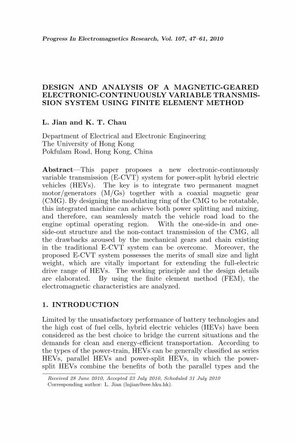
Thirdly, the torque transmission capability of the CMG can beassessed by calculating the Maxwell’s stress tensors in the airgapswhile keeping the outer rotor and the modulating ring standstill, androtating the inner rotor step by step. Fig. 10 depicts the resultingtorque-angle curves. It can be found that, the torque-angle curves varysinusoidally, in which the maximum torque values denote the pull-outtorques. Thus, the pull-out torques of the inner rotor, outer rotor andmodulating ring are 226.7Nm, 589.7Nm and 815.9 Nm, respectively.The ratio of the pull-out torques on the two rotors is 2.601, which has avery good agreement with the designed gear ratio of 2.6. In addition,the above three pull-out torques agree well with (5) since there is aphase difference of between the curve of the modulating ring and thecurves of the two rotors.
Progress In Electromagnetics Research, Vol. 107, 2010 57
Figure 10. Torque-angle curves of CMG.
(a) (b)
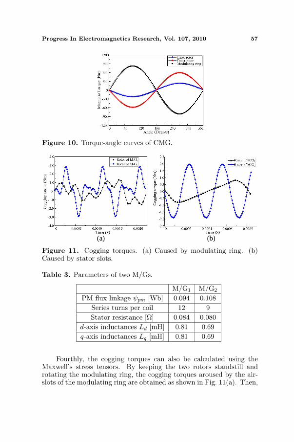
Figure 11. Cogging torques. (a) Caused by modulating ring. (b)Caused by stator slots.
Table 3. Parameters of two M/Gs.
M/G1 M/G2
PM flux linkage ψpm [Wb] 0.094 0.108Series turns per coil 12 9Stator resistance [Ω] 0.084 0.080
d-axis inductances Ld [mH] 0.81 0.69q-axis inductances Lq [mH] 0.81 0.69
Fourthly, the cogging torques can also be calculated using theMaxwell’s stress tensors. By keeping the two rotors standstill androtating the modulating ring, the cogging torques aroused by the air-slots of the modulating ring are obtained as shown in Fig. 11(a). Then,

58 Jian and Chau
by rotating the two rotors and the modulating ring simultaneously,the cogging torques aroused by the slots of the stators are obtained asshown in Fig. 11(b).
Finally, several important parameters can be calculated as listedin Table 3. Since non-salient PM poles are adopted in the twoM/Gs, their d-axis inductances Ld are almost the same with the q-axis inductances Lq. Fig. 12 shows both the current and voltageconstraints for operation of the M/Gs. The radius of the current limitcircle RI equals the rated current Irated, while the radius of the voltagelimit circle RU is proportional to the voltage limit Ulim and inverselyproportional to the rotational speed ωr,. The stator current is has to
Figure 12. Current and voltage constraints for operation of M/Gs.
(a) (b)
Figure 13. Torque-speed capabilities. (a) M/G1. (b) M/G2.

Progress In Electromagnetics Research, Vol. 107, 2010 59
be located in the overlapping area of both the voltage and current limitcircles. When the rotational speed is lower than the base speed, thestator current can be aligned along the q-axis to offer the maximumtorque/current operation, namely the constant-torque operation. Oncethe rotational speed exceeds the base speed, the stator current has todivert away from the q-axis, and the corresponding id will weaken thestator flux linkage to ensure that the back EMF is lower than thevoltage limit, namely the flux-weakening operation [19]. Fig. 13 showsthe resulting torque-speed capabilities of the two M/Gs.
5. CONCLUSION
In this paper, a new E-CVT system for power-split HEVs has beendesigned and analyzed by using FEM. The key is to integrate twoPM M/Gs together with a CMG. First, by purposely designing themodulating ring of the CMG to be rotatable, this integrated machinecan achieve both power splitting and mixing, and therefore canseamlessly match the vehicle road load to the engine optimal operatingregion. Then, with the one-side-in and one-side-out structure and thenon-contact transmission of the CMG, all the drawbacks aroused by themechanical gears and chain existing in the traditional E-CVT systemcan be overcome. Finally, the proposed E-CVT system possesses themerits of small size and light weight, which are vitally important forextending the full-electric drive range of HEVs.
ACKNOWLEDGMENT
This work was supported by a grant (Project No. HKU7105/07E)from the Research Grants Council, Hong Kong Special AdministrativeRegion, China.
REFERENCES
1. Chan, C. C. and K. T. Chau, Modern Electric Vehicle Technology,Oxford University Press, Oxford, 2001.
2. Chau, K. T. and C. C. Chan, “Emerging energy-efficienttechnologies for hybrid electric vehicles,” Proceedings of the IEEE ,Vol. 95, No. 4, 821–835, 2007.
3. Sasaki, S., “Toyota’s newly developed hybrid powertrain,” IEEEInternational Symposium on Power Semiconductor Devices andICs, 17–22, 1997.

60 Jian and Chau
4. Miller, J. M., “Hybrid electric vehicle propulsion systemarchitectures of the e-CVT type,” IEEE Trans. on PowerElectron., Vol. 21, No. 3, 756–767, 2006.
5. Hoeijmakers, M. J. and J. A. Ferreira, “The electric variabletransmission,” IEEE Trans. Ind. Appl., Vol. 42, No. 4, 1092–1100,2006.
6. Eriksson, S. and C. Sadarangani, “A four-quadrant HEV drivesystem,” IEEE Vehicular Technology Conference, 1510–1514,2002.
7. Atallah, K., S. Calverley, and D. Howe, “Design, analysis andrealization of a high-performance magnetic gear,” IEE Proc.Electric Power Appl., Vol. 151, No. 2, 135–143, 2004.
8. Jian, L. and K. T. Chau, “Analytical calculation of magneticfield distribution in coaxial magnetic gears,” Progress InEletromagnetics Research, Vol. 92, 1–16, 2009.
9. Chau, K. T., D. Zhang, J. Z. Jiang, C. Liu, and Y. Zhang, “Designof a magnetic-geared outer-rotor permanent-magnet brushlessmotor for electric vehicles,” IEEE Trans. Mag., Vol. 43, No. 6,2504–2506, 2007.
10. Jian, L., K. T. Chau, and J. Z. Jiang, “A magnetic-gearedouter-rotor permanent-magnet brushless machine for wind powergeneration,” IEEE Trans. Ind. Appli., Vol. 45, No. 3, 954–962,2009.
11. Faiz, J. and B. M. Ebrahimi, “Mixed fault diagnosis in three-phasesquirrel-cage induction motor using analysis of air-gap magneticfield,” Progress In Eletromagnetics Research, Vol. 64, 239–255,2006.
12. Vaseghi, B., N. Takorabet, and F. Meibody-Tabar, “Transientfinite element analysis of induction machines with stator windingturn fault,” Progress In Eletromagnetics Research, Vol. 95, 1–18,2009.
13. Faiz, J., B. M. Ebrahimi, and M. B. B. Sharifian, “Timestepping finite element analysis of broken bars fault in a three-phase squirrel-cage induction motor,” Progress In EletromagneticsResearch, Vol. 68, 53–70, 2007.
14. Chari, M., G. Bedrosian, J. D’Angelo, A. Konrad, G. Cotzas, andM. Shah, “Electromagnetic field analysis for electrical machinedesign,” Progress In Eletromagnetics Research, Vol. 04, 159–211,1991.
15. Jian, L. and K. T. Chau, “A coaxial magnetic gear with Halbachpermanent magnet arrays,” IEEE Trans. Energy Conv., Vol. 25,

Progress In Electromagnetics Research, Vol. 107, 2010 61
No. 2, 319–328, 2010.16. Liu, J. and H. Peng, “Modeling and control of a power-split hybrid
vehicle,” IEEE Trans. Control System Technol., Vol. 57, No. 1,1242–1251, 2008.
17. Jian, L., K. T. Chau, Y. Gong, J. Z. Jiang, C. Yu, and W. Li,“Comparison of coaxial magnetic gears with different topologies,”IEEE Trans. Magn., Vol. 45, No. 10, 4526–4529, 2009.
18. EL-Refaie, A. M., “Fractional-slot concentrated-windings syn-chronous permanent magnet machines: Opportunities and chal-lenges,” IEEE Trans. Ind. Electron., Vol. 57, No. 1, 107–121, 2010.
19. Sun, Z., J. Wang, G. Jewell, and D. Howe, “Enhanced optimaltorque control of fault-tolerant PM machine under flux-weakeningoperation,” IEEE Trans. Ind. Electron., Vol. 57, No. 1, 344–353,2010.


