Embed Size (px)
Citation preview
1-2-tree: Semantic Modeling and Editing of Trees
Bjorn Ganster, Reinhard Klein
Universitat BonnEmail: {ganster,rk}@uni-bonn.de
Abstract
In computer graphics, procedural methods and L-systems are common approaches to model complexbotanical trees. In contrast to previous tree mod-eling systems, we propose linking rules, parame-ters and geometry to semantic entities. This has theavantage that when an entity is clicked in the view-port, its parameters can be displayed immediately,and viewport editing operations can be reflected inthe parameter set. Furthermore, we store the entitiesin a hierarchical data structure and allow the user toactivate recursive traversal via selection options forall editing operations. Therefore, viewport or pa-rameter changes can be applied to a single entity ormany entities at once, and only the geometry for theaffected entities needs to be updated. The proposeduser interface aims at simplifying the modeling pro-cess.
1 Introduction
Modeling trees has been a topic for decades incomputer graphics, with applications in areassuch as films, computer games, advertising andarchitecture visualization, because outdoor scenesusually include trees. Current tree modeling toolsare often powerful, but difficult to handle, orthey are easy to use, but unable to capture theuniqueness of particular trees. Research in this areahas reached a point where we can focus on makingthe modeling process easy for users without abackground in computer graphics. For that reason,we aim to balance very powerful, but difficult-to-use systems with simpler, less powerful approaches.
Procedural systems for modeling trees use aprinciple for which Alvy Ray Smith coined theterm data amplification paradigm [29]: It describeshow complex models can be constructed froma small set of rules and some input parameters.
Unfortunately, previous tree modeling systemscreate the geometry as an unstructured list ofpolygons, without associating rules with theirgeometry instances.
Linking the geometry closely with the parame-ters used for geometry construction is a strengthof conventional modeling systems like 3DS Max,Maya, or Cinema4D, because local changes can bemade without affecting the whole model or entail-ing a complete reconstruction. However, due to thesheer number of primitives, exclusively modeling acomplex tree in this manner is impractical.
In the sketch-based modeling approach, the usercreates a rough sketch of an object, and algorithmsinfer a 3D model from this input. This shifts theresponsibility for managing the primitives to thecomputer, but altering the model requires a newsketch or different tools.
By integrating the procedural, conventional mod-eling and sketch-based approaches into a singlesystem, we combine their strengths and eliminatetheir weaknesses: We use a procedural model tocreate instances, but we link the parameters withtheir geometry instances to form semantic entitiesin a hierarchical data structure. This permits us tochange single instances or to perform mass updatesafter geometry creation without reconstructingthe entire model. Sketch-based modeling yieldsadditional methods for input, and the user canmodel on a semantic level after sketching. We callthis semantic modeling because we are dealing withentities rather than abstract rules or raw geometry.
We use a single hierarchical data structure tostore both the geometry and parameters for allbranches of a tree. This paper’s main contributionsare exposing the hierarchy traversals during updatesas selection options and retrieving branch parame-
VMV 2008 O. Deussen, D. Keim, D. Saupe (Editors)
ters from interactive changes in the viewport. Thispaper proposes a user interface and algorithms toease modeling trees, but it does not aim at creatingmore realistic models.
2 Related Work
2.1 Procedural modeling of trees
Aristid Lindenmayer [12] introduced a notation formodeling growth processes in 1968. Named aftertheir inventor, L-systems apply rewriting rules toan axiom to produce a linear symbolic descriptionof a plant, the L-string. An L-system requires thatall matches for a rule are applied in parallel, and aninput parameter states the number of parallel rewrit-ing steps to perform before the system terminates.The next stage in the algorithm produces geometryfrom the L-string. Lindenmayer and Prusinkiewiczdescribe this process with several extensions intheir book [21]. Prunsinkiewicz et al publisheda series of extensions: interaction with the envi-ronment [15], an application to topiary [22], andthe use of positional information [23]. Positionalinformation is taken from a 2D function editorto change parameter values along the parent branch.
Honda describes a procedural approach thatcreated the first 3D plant skeletons [9, 2]. Reevesinvented particle systems, and describes an applica-tion to trees together with Blau [26]. Oppenheimerproposed a recursive algorithm inspired by Man-delbrot’s fractals [19]. He needs few parametersto describe trees because he uses recursion factors.Bloomenthal demonstrated how to produce realisticbranches [3]. de Reffye et al animate tree growthusing procedural models [5]. Greene showed howto use voxel grids to speed up queries that preventself-intersection and allow to simulate heliotropism[7]. Holton proposed the strand model to calculaterealistic branching angles, radii and branch lengths[8].
Weber and Penn propose a parameterization fortrees designed for use by non-experts [31]. In par-ticular, they replace the recursion factors used byOppenheimer with 13 parameters that apply to allbranches on the same level of recursion. Therefore,parameter changes always affect all branches on thesame level. There are special parameters with a ’V’
suffix which define a maximum random deviationfrom the base parameter. The paper provides manyexamples demonstrating that the parameters sufficefor modeling a wide range of trees.
Lintermann and Deussen designed a graphicalprogramming language to describe trees, flowersand other plants [13]. Parameters can be varied byassigning mathematical functions which evaluateiteration counts or use pseudo random numbergenerators.
Power et al apply an inverse kinematics opti-mization technique to create a natural branch formwhile a user drags a branch, and branches can bebent, rotated or pruned in the viewport [20].
Since Weber and Penn published their system,computers have evolved to a point where it is pos-sible to store parameters for individual branches, asdemonstrated by Boudon et al [4] for L-systems.Their system collects parameters in a hierarchicaldata structure called decomposition graph. Theparameters can be inherited to child branches,similar to the inheritance mechanism used inobject-oriented programming languages. Theuser may edit the silhouette of a branch includingsub-levels, and an L-system fills it with the nextlevel of branches and leaves.
2.2 Image-based modeling of trees
More recently, research has focused on reproducingexisting plants from images [25, 27, 28]. Quanet al’s system allows the user to draw and movecurves, to edit the radius of a branch, or to placeleaves in the 3D viewport [24]. The system byNeubert et al [16] requires only few input imagesand permits sketching. The user provides onlyapproximate positions for the images, and noregistration is needed.
2.3 Sketch-based modeling of trees
Sketch interfaces allow a user to create a 2D sketchfrom which the computer derives a 3D model. Thishas been demonstrated for trees, flowers [11] andphyllotactic arrangement of plant organs [1]. Okabeet al presented a system that deduces a 3D model of
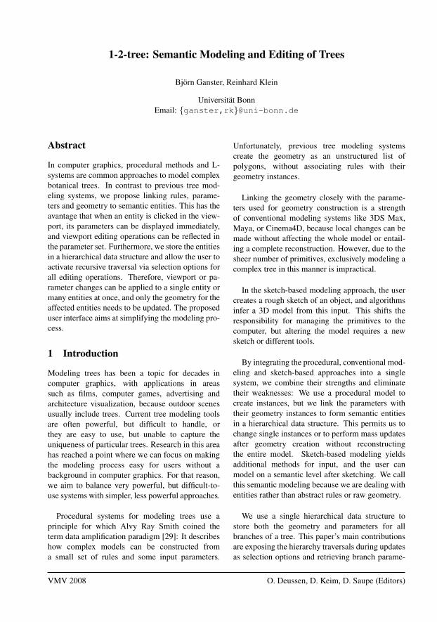
a b c d e
Figure 1: Modeling a plane tree in 1-2-tree. a) The trunk and the main branches are modeled individually.b+c+d) Further branches are added using mass updates. e) Result after adding leaves.
a tree from a sketch, by assuming that trees spreadbranches so that the distances between the branchesare maximized [18]. The system integrates threeexample-based interaction techniques that can beused to alter the model after the geometry has beencreated. The Sketch L-system by Ijiri et al allowsthe user to edit production rules in the 3D viewport[10]. The system applies the production rules inter-actively while the user sketches the trunk.
3 Overview
Our system treats tree organs such as the trunk,branches, twigs, roots, leaves, blossoms and fruitsas semantic entities. The entities have simpleparameters such as their size and color. Furtherparameters control placement and orientation of thetree organs. In this paper, we focus on the branchesand leaves as the most important entities that definethe tree structure and visual appearance, but futureimplementations could include other entities. Asin other publications, the term “branches” includesthe trunk, any twigs, and even roots.
The entities are stored in a simplified scenegraph [30], where all nodes represent branches. Al-gorithms that alter parameters or update geometryhave recursive scene graph traversal as a built-infeature. We expose the recursive data structureupdates to the user as selection options. Thus,the user may choose to apply parameter changesto a single branch or several branches at once. Anotation for positional information ensures variety.
Every entity has two representations: one is itsparameterization, the other is its geometry. Westore both representations in the scene graph node.This has a number of benefits: When the user se-
lects an entity in the viewport, our system displaysits parameters. When the user edits the geometryin the viewport, our system adjusts the entities’parameters. Any changes to the parameters orthe geometry are interactively applied to the otherrepresentation and optionally to other instances.Only the geometry for the affected nodes needs tobe rebuilt.
The new system is designed to allow for fast andeasy creation of trees, thus its name 1-2-tree (“easyas counting one-two-t(h)ree”).
4 Using 1-2-tree
We propose the following user interface: Whenthe user starts the system, the trunk for a newtree is displayed. Branches are added by settingthe number of child branches to nonzero or bysketching them in the viewport. All branches canbe edited directly in the viewport or by adjustingtheir parameters. For capturing the uniqueness ofspecific trees, it often makes sense to model thetrunk and some of the main branches individually,but as modeling a tree progresses, minor branchesand twigs are usually best edited using massupdates. Leaves are usually added as a last step, asthey hide the tree’s inner structure. See Figure 1 foran example.
4.1 Selection
The user may select branches in the viewport. In or-der to perform mass updates, further branches canbe added to the selection using the following selec-tion modes:• Same Level: Selects all branches on the same
branch level,• Recursive: Adds the selected branches’ chil-
dren to the selection.If both options are active, changes affect all
branches on the same level and below the currentlyselected branch. If the trunk is selected and recur-sive selection is active, editing operations affect theentire tree.
There may be several kinds of child branches ona branch. For the trunk, there may be a few mainbranches, many small branches near its top, andthe roots can be modeled as branches, too. Theuser may define groups of branches by assigningtags, and may limit updates to branches that carrythe selected branch’s tag. With properly assignedtags, it is therefore possible to edit only the mainbranches, for example.
Since all editing operations are applied to allselected branches, the selection modes permit theuser to perform powerful editing operations in anintuitive manner.
4.2 Viewport tools
The branches are defined by control points andradii, which are stored in the scene graph node.The following tools may be used to manipulate thecontrol points in the viewport:
The “Move” tool allows moving branch controlpoints. All following control points on the samebranch, its child branches and all branches inthe selection are translated by the same vector.Another viewport tool interactively rotates thecurrently selected branches against their parents inthe viewport. The parameters “Length” and “Angleagainst Parent” are updated for the entire selection.
The “Sketch” tool allows for sketching branchesdirectly in the viewport. The user moves the mouseover the parent branch to select a starting point and
then sketches the new branch. After sketching, thenew branch lies in a plane, but the user can movethe control points from a different perspective.
The currently selected branch can be deleted bypressing the DEL key. The user may delete thetrunk in this manner and sketch a new one. The“Saw” tool can be used to cut off branch parts at themouse position. It was implemented as a replace-ment for pruning.
4.3 Parameters
While sketching and moving control points workswell for editing individual branches, editing manybranches at a time can often be accomplished moreeasily by manipulating parameters. Our parametersare very similar to those of Weber and Penn [31],except that we store individual parameters foreach branch. In order to increase variety duringmass updates, we created a simple notation thatallows the user to combine parameter increasesor decreases along the parent branch with a noisefunction. This is a simplified form of positionalinformation [23]. Please refer to Appendix A fordetails on the notation and the parameter list.
For many trees, smaller branches and leaves areconcentrated near the hull of the tree. We modelthis observation by introducing the “anchor values”parameter: Every branch’s anchor value selects thecontrol points to use for placing the branch. Thestarting point ~q for a child branch with anchor valuea and n parent branch control points p0, ..., pn−1 iscomputed by interpolation
~q =
{~pk + (j − k)(~pk+1 − ~pk) if 0 < a < 1~p0 if a ≤ 0~pn−1 if a ≥ 1
where j = a(n− 1) and k = bjc. The user mayrestrict branches and leaves to the outer areas of atree by specifying an interval for the anchor values.For example, assigning “0.5-1” as an anchor valuewill place branches only on the outer half of abranch.
BranchParametersGeometry
Child branches
Parameter changesStore
RecalculateRecurse
¡¡
¡µ
¡¡
¡µ
¡¡
¡ª
¡¡
¡µ
SketchingRecalculate HHHj@
@@R
Viewport changesStore
RecalculateRecurse
À
©©©¼
¡¡
¡µ
RenderRenderRecurse
@@
@R@@
@R
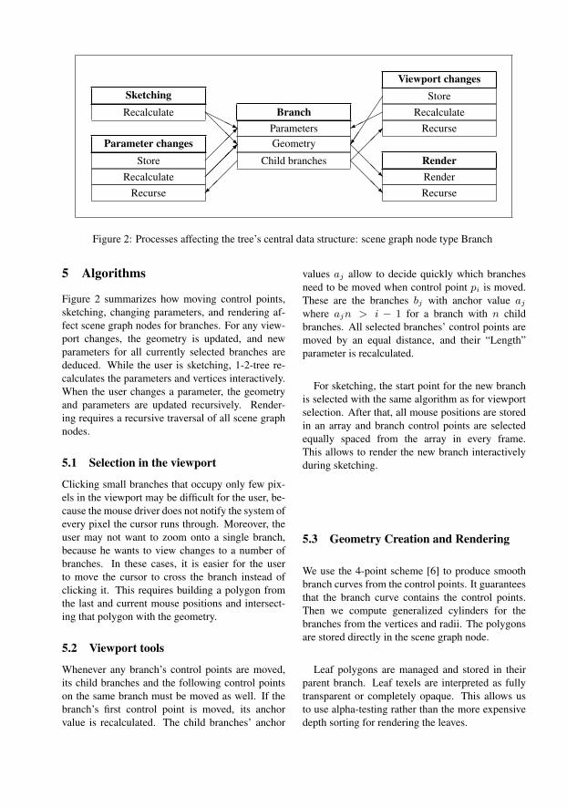
Figure 2: Processes affecting the tree’s central data structure: scene graph node type Branch
5 Algorithms
Figure 2 summarizes how moving control points,sketching, changing parameters, and rendering af-fect scene graph nodes for branches. For any view-port changes, the geometry is updated, and newparameters for all currently selected branches arededuced. While the user is sketching, 1-2-tree re-calculates the parameters and vertices interactively.When the user changes a parameter, the geometryand parameters are updated recursively. Render-ing requires a recursive traversal of all scene graphnodes.
5.1 Selection in the viewport
Clicking small branches that occupy only few pix-els in the viewport may be difficult for the user, be-cause the mouse driver does not notify the system ofevery pixel the cursor runs through. Moreover, theuser may not want to zoom onto a single branch,because he wants to view changes to a number ofbranches. In these cases, it is easier for the userto move the cursor to cross the branch instead ofclicking it. This requires building a polygon fromthe last and current mouse positions and intersect-ing that polygon with the geometry.
5.2 Viewport tools
Whenever any branch’s control points are moved,its child branches and the following control pointson the same branch must be moved as well. If thebranch’s first control point is moved, its anchorvalue is recalculated. The child branches’ anchor
values aj allow to decide quickly which branchesneed to be moved when control point pi is moved.These are the branches bj with anchor value aj
where ajn > i − 1 for a branch with n childbranches. All selected branches’ control points aremoved by an equal distance, and their “Length”parameter is recalculated.
For sketching, the start point for the new branchis selected with the same algorithm as for viewportselection. After that, all mouse positions are storedin an array and branch control points are selectedequally spaced from the array in every frame.This allows to render the new branch interactivelyduring sketching.
5.3 Geometry Creation and Rendering
We use the 4-point scheme [6] to produce smoothbranch curves from the control points. It guaranteesthat the branch curve contains the control points.Then we compute generalized cylinders for thebranches from the vertices and radii. The polygonsare stored directly in the scene graph node.
Leaf polygons are managed and stored in theirparent branch. Leaf texels are interpreted as fullytransparent or completely opaque. This allows usto use alpha-testing rather than the more expensivedepth sorting for rendering the leaves.

Hazel Oak tree Poplar Silver Linden
Figure 3: Example trees
Species Modeling time #Branches #Leaves #Branch levels Geometry ParametersHazel 4 min 58 s 2,221 17,939 4 21.9 MB 1.1 MBOak 5 min 03 s 9,931 57,228 4 22.3 MB 4.7 MBSilver Linden 7 min 33 s 2,211 7,048 4 21.7 MB 1.1 MBPoplar 3 min 29 s 6,631 27,483 4 32.4 MB 3.1 MBAsh Tree 4 min 37 s 221 680 4 689.0 kB 106.5 kBBeech Tree 5 min 57 s 7,517 187,000 5 23.8 MB 3.5 MBAhorn ca 25min 34,001 393,822 5 75.5 MB 15.7 MBBirch Tree 8 min 37 s 23,011 99,190 5 114.0 MB 10.9 MBPlane Tree ca. 9min 14,373 204,138 5 18.8 MB 7.0 MB
Table 1: Statistics for creating the trees in Figures 1, 3, 4
5.4 Persistence
In procedural modeling, the persistence problemrefers to the difficulty of retaining user edits afterparts of the model were changed [4, 14]. The naiveapproach to change the number of branches on aparent branch uses one of the old branches as a tem-plate for creating the new branches. However, if oneof the deleted branches was edited with individualparameters, these parameters are lost. Therefore,instead of deleting branches, the existing branchesshould be moved to their positions, and then theirpositional information should be re-evaluated. As-signing tags further reduces the impact of changingthe number of branches.
6 Results
1-2-tree recreates geometry only for scene graphnodes that were changed, and these changes areapplied fast enough that parallel execution is notneeded. Table 1 lists memory usage and timeneeded to model the trees shown in this paper.The amount of memory needed to store the ge-ometry usually exceeds the memory needed forthe parameters by a factor of at least 2. Giventoday’s memory sizes, we think the added cost ofindividual parameters for each branch is affordablefor editing single trees.
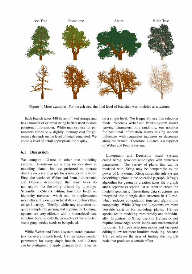
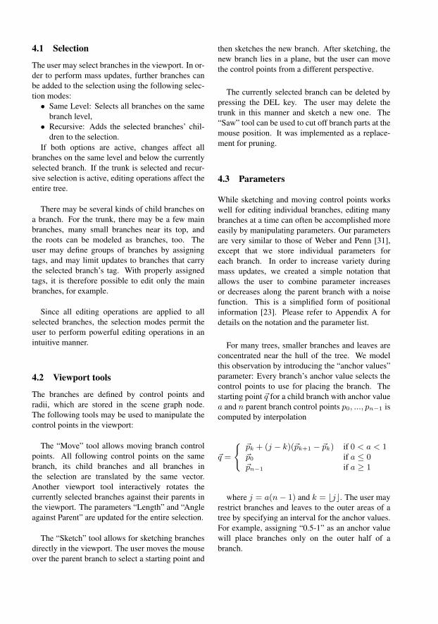
Ash Tree Beech tree Ahorn Birch Tree
Figure 4: More examples. For the ash tree, the final level of branches was modeled as a texture.
Each branch takes 440 bytes of fixed storage andhas a number of external string buffers used to storepositional information. While memory use for pa-rameters varies only slightly, memory cost for ge-ometry depends on the level of detail generated. Wechose a level of detail appropriate for display.
6.1 Discussion
We compare 1-2-tree to other tree modelingsystems. L-systems are a long success story inmodeling plants, but we preferred to operatedirectly on a scene graph for a number of reasons.First, the works of Weber and Penn, Lintermannand Deussen demonstrate that most trees donot require the flexibility offered by L-strings.Secondly, 1-2-tree’s editing functions build onhierarchy traversal, which can be implementedmore efficiently on hierarchical data structures thanon an L-string. Thirdly, while any alteration re-quires completely parsing and copying the L-string,updates are very efficient with a hierarchical datastructure because only the geometry of the affectedscene graph nodes needs to be updated.
While Weber and Penn’s system stores parame-ters for every branch level, 1-2-tree stores similarparameters for every single branch, and 1-2-treecan be configured to apply changes to all branches
on a single level. We frequently use this selectionmode. Whereas Weber and Penn’s system allowsvarying parameters only randomly, our notationfor positional information allows mixing randominfluences with parameter increases or decreasesalong the branch. Therefore, 1-2-tree is a supersetof Weber and Penn’s system.
Lintermann and Deussen’s visual system,called Xfrog, provides node types with numerousparameters. The variety of plants that can bemodeled with Xfrog may be comparable to thepower of L-systems. Xfrog stores the rule systemdescribing a plant in the so-called p-graph. Xfrog’salgorithm for geometry creation takes the p-graphand a separate exception list as input to create themodel’s geometry. These three data structures areintegrated into a single data structure in 1-2-tree,which reduces computation time and algorithmiccomplexity. While Xfrog and L-systems are moreversatile systems for modeling plants, 1-2-treespecializes in modeling trees rapidly and individu-ally. In contrast to Xfrog, users of 1-2-tree do notrequire knowledge about loops and mathematicalformulae. 1-2-tree’s selection modes and viewportediting allow for more intuitive modeling, because1-2-tree relieves the user of finding the p-graphnode that produces a certain effect.
Like 1-2-tree, Boudon et al’s system storesindividual parameters for each branch. In 1-2-tree,copying changes to other nodes is governed byintuitive selection settings rather than inheritancesettings. 1-2-tree integrates the functionalityof Boudon et al’s decomposition graph and thebranching structure browser into the 3D viewportto further ease modeling.
The system by Okabe et al [17] is orthogonalto ours. It focuses on sketch- and example-basedmodelling, whereas 1-2-tree focuses on proceduralmodeling and direct editing methods. Both ap-proaches have their advantages, and future usersmight want to have a system that integrates thestrengths of both systems.
Boudon et al report an average modeling timeof 3 hours for each model [4], and Okabe et al’smodels took less than 10 minutes on average [17].In 1-2-tree most models take between 4 and 10minutes to create.
7 Conclusion
We tried to balance the various approaches and usesketching where it is strongest, which is modelingindividual branches. We feel that deriving parame-ters from viewport input and applying the derivedparameters to other instances nicely combinesprocedural modeling and sketch-based interfaces.We focused on creating a system that gives the usermaximum control over the process of modelingtrees without requiring him to learn concepts likeloops, grammars and mathematical formulae. Thisreduces the flexibility of 1-2-tree, but greatlyenhances the ease of use. Simple tree modelscan usually be created within a few minutes, andarbitrary precision can be obtained by modelingindividual branches.
We have demonstrated the benefits of storingbranches as semantic entities in a hierarchical datastructure for modeling trees. Among these bene-fits are the powerful selection options for changingeither single entities or masses of branches. More-over, we have shown that this data structure can beused to propagate viewport changes back to the pa-rameters.
7.1 Future Work
The system proposed here could be extended toedit trees that were reconstructed from images andto determine parameter distributions of real trees.The system would take a number of images asinput, compute tree skeletons, conclude parameterdistributions and finally use these parameters tocreate other trees of the same species. The samealgorithm should compute branch textures from theinput images.
1-2-tree could be improved by more options andbetter algorithms for automatic radius calculation,branch and leaf placement.
7.2 Acknowledgments
We would like to thank Martin Schneider, RolandWahl, Lisa Schutzendorf, and Klaus Greulich fordiscussions and advice.
A Parameters
We use a simplified notation to mimic the effects ofpositional information. The notation a-b increasesor decreases the value along the parent branch froma to b. In order to introduce random variations, aparameter can be stated as cud, meaning a uniformdistribution with an expected value of c and amaximum deviation of d. Both notations can bemixed: aub-cud. This notation allows to interpolatebetween randomly distributed values, therefore wecall it an interpolated distribution for short.
Parameters are stored individually for eachbranch, and are sorted into categories. Cate-gory “Branch Parameters” defines basic branchproperties, such as the branch’s length and itsnumber of control points. Further parametersinclude “Gnarl”: maximum random deviationfrom a straight branch, “Gravitropism”: a grav-itational effect bending a branch down or up,“Subdivision Steps”: number of subdivision stepsused to produce smooth branches, “Complexity”:number of polygons to create for each generalizedcylinder, “CPS”: allows assigning the currentlyselected branches to a different child parameterset. This is useful to protect branches from changes.
The category “Radius Parameters” containsparameters for editing the branch radius and but-tons for calculating radii automatically. There areparameters for the radius at the start (“Radius”) andat its end (“Min. Radius”). The button “CalculateRadius” calculates radii from “Min. Radius” usingda Vinci’s law for branch radii [8].
The category “Child branches” governs childbranches. Its parameters are the “Number ofBranches”, “Anchor values”. It is possible toconfigure these parameters for several separatechild parameter sets (CPS).
The category “Angles” pools parameters thatmodel a branch’s angle against sibling and parentbranch. The category “Leaf” parameters containssimilar parameters for leaves to the parametersexplained before.
Category “Bark” allows creating a simple noisetexture to use as bark. Small green branches canbe used to produce the needles for a conifer. Inthat case, “Control Point Count”, “Complexity”and “Subdivision Steps” should be set to minimumvalues to reduce the number of polygons created.
References
[1] Fabricio Anastacio, Mario Costa Sousa, Fara-marz Samavati, and Joaquim A. Jorge. Mod-eling plant structures using concept sketches.In NPAR ’06: Proceedings of the 4th interna-tional symposium on Non-photorealistic ani-mation and rendering, pages 105–113, 2006.
[2] M. Aono and T. Kunii. Botanical tree imagegeneration. Computer Graphics and Applica-tions, IEEE, 4(5):10–34, May 1984.
[3] Jules Bloomenthal. A representation forbotanical trees using density distributions. In1st Int’l Conf. on Engineering and ComputerGraphics, 1984.
[4] Frederic Boudon, Przemyslaw Prusinkiewicz,Pavol Federl, Christophe Godin, and Ra-doslaw Karwowski. Interactive design of bon-sai tree models. In Proceedings of Eurograph-ics 2003: Computer Graphics Forum 22 (3),pages 591–599, 2003.
[5] Phillippe de Reffye, Claude Edelin, JeanFrancon, Marc Jaeger, and Claude Puech.Plant models faithful to botanical structureand development. In SIGGRAPH ’88:Proceedings of the 15th annual conferenceon Computer graphics and interactive tech-niques, pages 151–158, 1988.
[6] N. Dyn, J. Gregory, and D. Levin. A 4-point interpolatory scheme for curve design.In CAGD 4 (1987), pages 257–268, 1987.
[7] N. Greene. Voxel space automata: model-ing with stochastic growth processes in voxelspace. In SIGGRAPH ’89: Proceedings of the16th annual conference on Computer graphicsand interactive techniques, pages 175–184,1989.
[8] M. Holton. Strands, gravity and botanical treeimagery. Computer Graphics Forum 13 (1),pages 57–67, 1994.
[9] Hisao Honda. Description of the form of treesby the parameters of the tree-like body: Ef-fects of the branching angle and the branchlength on the shape of the tree-like body. Jour-nal of Theoretical Biology, pages 331–338,1971.
[10] Takashi Ijiri, Shigeru Owada, and TakeoIgarashi. The sketch L-system: Global con-trol of tree modeling using free-form strokes.In 6th International Symposium on SmartGraphics 2006, LNCS 4073, pages 138–146.Springer Verlag, 2006.
[11] Takashi Ijiri, Shigeru Owada, Makoto Okabe,and Takeo Igarashi. Floral diagrams and in-florescences: interactive flower modeling us-ing botanical structural constraints. In SIG-GRAPH ’05: ACM SIGGRAPH 2005 Papers,pages 720–726, 2005.
[12] Aristid Lindenmayer. Mathematical modelsfor cellular interactions in development, partsI and II. Journal of Theoretical Biology,18:280–315, 1968.
[13] Bernd Lintermann and Oliver Deussen. Amodelling method and user interface for cre-ating plants. Computer Graphics Forum,17(1):73–82, 1998.
[14] Markus Lipp, Peter Wonka, and MichaelWimmer. Interactive visual editing of gram-mars for procedural architecture. In Proceed-ings of ACM SIGGRAPH 2008, 2008.
[15] Radomır Mech and Przemyslaw
Prusinkiewicz. Visual models of plantsinteracting with their environment. InSIGGRAPH ’96: Proceedings of the 23rdannual conference on Computer graphics andinteractive techniques, pages 397–410, NewYork, 1996. ACM.
[16] Boris Neubert, Thomas Franken, and OliverDeussen. Approximate image-based tree-modeling using particle flows. ACM Trans-actions on Graphics, 2007.
[17] Makoto Okabe and Takeo Igarashi. 3d mod-eling of trees from freehand sketches. In SIG-GRAPH ’03: ACM SIGGRAPH 2003 Sketches& Applications, pages 1–1, 2003.
[18] Makoto Okabe, Shigeru Owada, and TakeoIgarashi. Interactive design of botanical treesusing freehand sketches and example-basedediting. In Proceedings of Eurographics 2005:Computer Graphics Forum 24 (3), pages 487–496, 2005.
[19] Peter E. Oppenheimer. Real time design andanimation of fractal plants and trees. In Com-puter Graphics (Proceedings of SIGGRAPH86), pages 55–64, 1986.
[20] Joanna L. Power, A. J. Bernheim Brush, Prze-myslaw Prusinkiewicz, and David H. Salesin.Interactive arrangement of botanical L-systemmodels. In I3D ’99: Proceedings of the 1999symposium on Interactive 3D graphics, pages175–182, 1999.
[21] P. Prusinkiewicz and Aristid Lindenmayer.The algorithmic beauty of plants. Springer-Verlag, New York, 1990.
[22] Przemyslaw Prusinkiewicz, Mark James, andRadomır Mech. Synthetic topiary. In SIG-GRAPH ’94: Proceedings of the 21st annualconference on Computer graphics and inter-active techniques, pages 351–358, New York,1994. ACM.
[23] Przemyslaw Prusinkiewicz, LarsMundermann, Radoslaw Karwowski, andBrendan Lane. The use of positional in-formation in the modeling of plants. InSIGGRAPH ’01: Proceedings of the 28thannual conference on Computer graphics andinteractive techniques, pages 289–300, NewYork, 2001. ACM.
[24] Long Quan, Ping Tan, Gang Zeng, Lu Yuan,Jingdong Wang, and Sing Bing Kang. Image-based plant modeling. In SIGGRAPH ’06:
ACM SIGGRAPH 2006 Papers, pages 599–604, 2006.
[25] Alex Reche-Martinez, Ignacio Martin, andGeorge Drettakis. Volumetric reconstructionand interactive rendering of trees from pho-tographs. In SIGGRAPH ’04: ACM SIG-GRAPH 2004 Papers, pages 720–727, 2004.
[26] William T. Reeves and Ricki Blau. Approxi-mate and probabilistic algorithms for shadingand rendering structured particle systems. InSIGGRAPH ’85: Proceedings of the 12th an-nual conference on Computer graphics and in-teractive techniques, pages 313–322, 1985.
[27] Tatsumi Sakaguchi and Jun Ohya. Modelingand animation of botanical trees for interactivevirtual environments. In VRST ’99: Proceed-ings of the ACM symposium on Virtual real-ity software and technology, pages 139–146,1999.
[28] Ilya Shlyakhter, Max Rozenoer, Julie Dorsey,and Seth Teller. Reconstructing 3d tree modelsfrom instrumented photographs. IEEE Com-puter Graphics and Applications, 21(3):53–61, 2001.
[29] Alvy Ray Smith. Plants, fractals, and for-mal languages. In Computer Graphics (Pro-ceedings of ACM SIGGRAPH 84), pages 1–10, New York, 1984. ACM Press.
[30] Paul S. Strauss and Rikk Carey. An object-oriented 3D graphics toolkit. In ComputerGraphics (Proceedings of ACM SIGGRAPH92), pages 341–349, New York, 1992. ACMPress.
[31] Jason Weber and Joseph Penn. Creation andrendering of realistic trees. In SIGGRAPH’95: Proceedings of the 22nd annual confer-ence on Computer graphics and interactivetechniques, pages 119–128, 1995.