Embed Size (px)
Citation preview
1
Chapter 10. Cellular Wireless Networks
Wen-Shyang HwangKUAS EE.
2
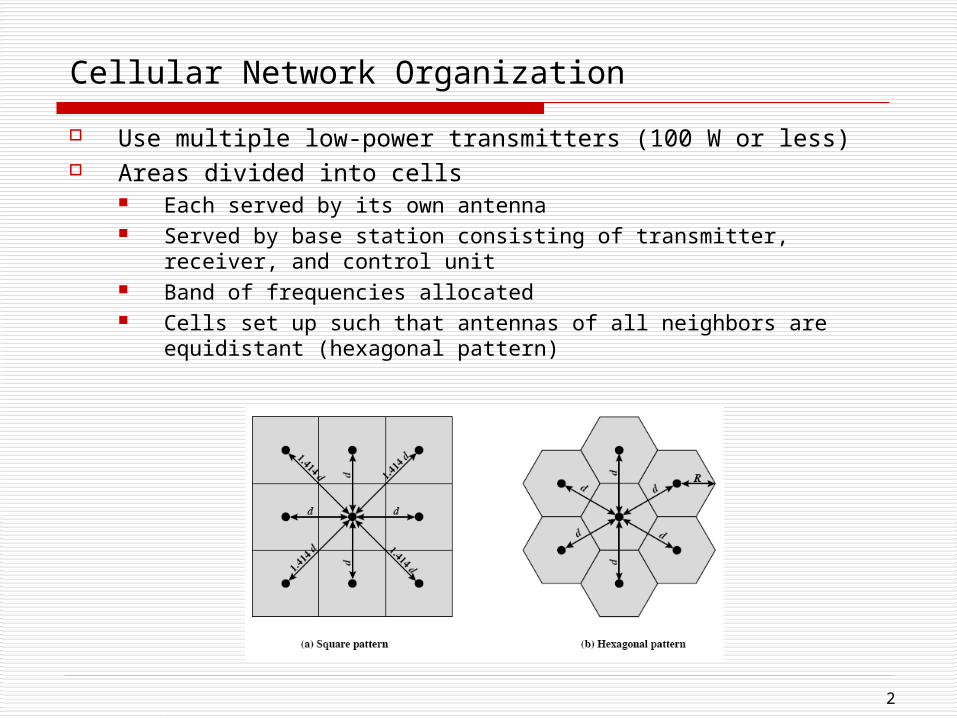
Cellular Network Organization
Use multiple low-power transmitters (100 W or less) Areas divided into cells
Each served by its own antenna Served by base station consisting of transmitter, receiver, and
control unit Band of frequencies allocated Cells set up such that antennas of all neighbors are equidistant
(hexagonal pattern)
3
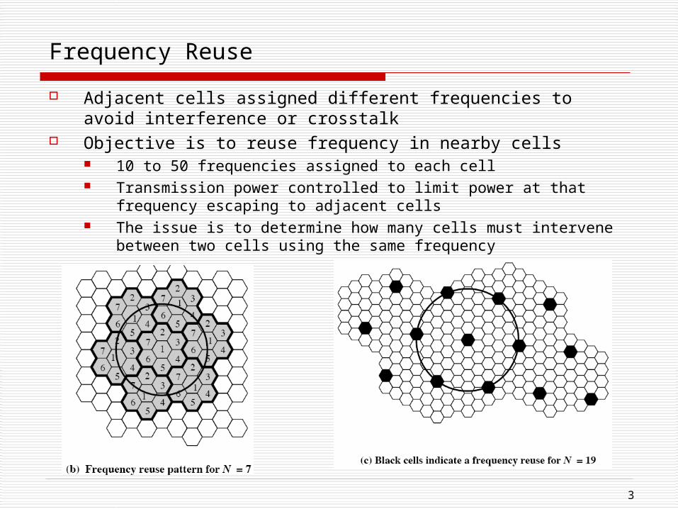
Frequency Reuse
Adjacent cells assigned different frequencies to avoid interference or crosstalk
Objective is to reuse frequency in nearby cells 10 to 50 frequencies assigned to each cell Transmission power controlled to limit power at that frequency
escaping to adjacent cells The issue is to determine how many cells must intervene between
two cells using the same frequency
4
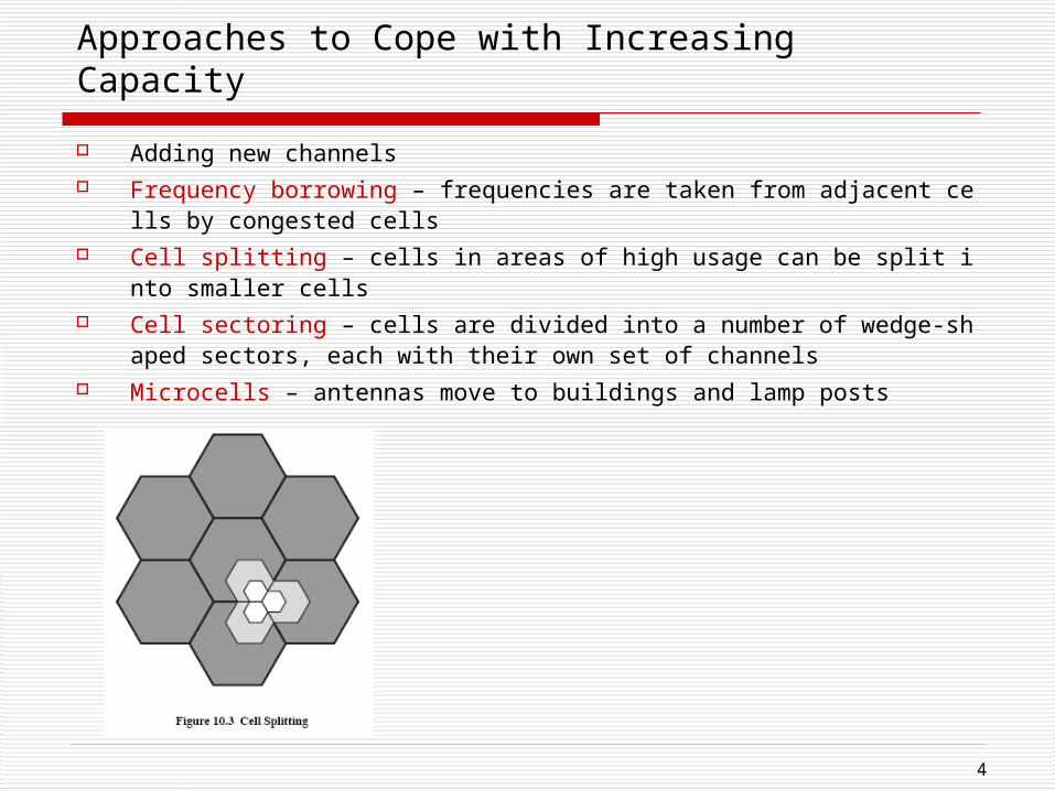
Approaches to Cope with Increasing Capacity
Adding new channels Frequency borrowing – frequencies are taken from adjacent cells by congeste
d cells Cell splitting – cells in areas of high usage can be split into smaller cells Cell sectoring – cells are divided into a number of wedge-shaped sectors, eac
h with their own set of channels Microcells – antennas move to buildings and lamp posts
5
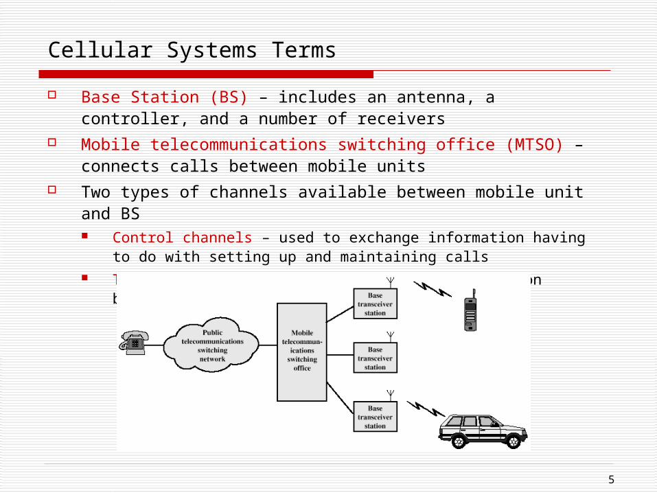
Cellular Systems Terms
Base Station (BS) – includes an antenna, a controller, and a number of receivers
Mobile telecommunications switching office (MTSO) – connects calls between mobile units
Two types of channels available between mobile unit and BS Control channels – used to exchange information having to do with
setting up and maintaining calls Traffic channels – carry voice or data connection between users
6
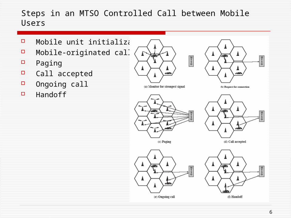
Steps in an MTSO Controlled Call between Mobile Users
Mobile unit initialization Mobile-originated call Paging Call accepted Ongoing call Handoff
7
Other Functions in an MTSO Controlled Call
Call blocking – busy tone Call termination – channel released Call drop – interference or weak signal Calls to/from fixed and remote mobile subscriber – connect to
PSTN
8
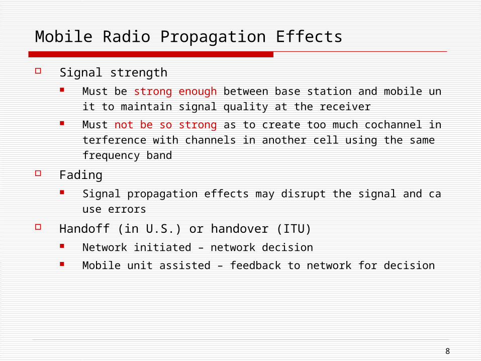
Mobile Radio Propagation Effects
Signal strength Must be strong enough between base station and mobile unit to maintai
n signal quality at the receiver Must not be so strong as to create too much cochannel interference with
channels in another cell using the same frequency band Fading
Signal propagation effects may disrupt the signal and cause errors Handoff (in U.S.) or handover (ITU)
Network initiated – network decision Mobile unit assisted – feedback to network for decision
9
Handoff Performance Metrics used to decide
Cell blocking probability – probability of a new call being blocked Call dropping probability – probability that a call is terminated due to a hand
off Call completion probability – probability that an admitted call is not dropped
before it terminates Probability of unsuccessful handoff – probability that a handoff is executed w
hile the reception conditions are inadequate Handoff blocking probability – probability that a handoff cannot be successfu
lly completed Handoff probability – probability that a handoff occurs before call terminatio
n Rate of handoff – number of handoffs per unit time Interruption duration – duration of time during a handoff in which a mobile is
not connected to either base station Handoff delay – distance the mobile moves from the point at which the hando
ff should occur to the point at which it does occur
10
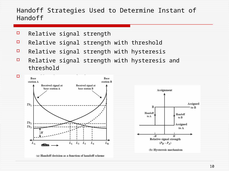
Handoff Strategies Used to Determine Instant of Handoff
Relative signal strength Relative signal strength with threshold Relative signal strength with hysteresis Relative signal strength with hysteresis and threshold Prediction techniques
11
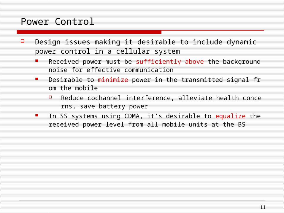
Power Control
Design issues making it desirable to include dynamic power control in a cellular system Received power must be sufficiently above the background noise for effe
ctive communication Desirable to minimize power in the transmitted signal from the mobile
Reduce cochannel interference, alleviate health concerns, save battery power
In SS systems using CDMA, it’s desirable to equalize the received power level from all mobile units at the BS
12
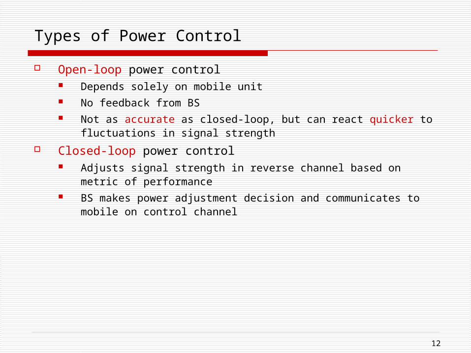
Types of Power Control
Open-loop power control Depends solely on mobile unit No feedback from BS Not as accurate as closed-loop, but can react quicker to
fluctuations in signal strength
Closed-loop power control Adjusts signal strength in reverse channel based on metric of
performance BS makes power adjustment decision and communicates to mobile
on control channel
13
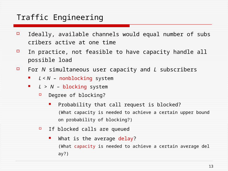
Traffic Engineering
Ideally, available channels would equal number of subscribers active at one time
In practice, not feasible to have capacity handle all possible load For N simultaneous user capacity and L subscribers
L < N – nonblocking system L > N – blocking system
Degree of blocking? Probability that call request is blocked?
(What capacity is needed to achieve a certain upper bound on probability of blocking?)
If blocked calls are queued What is the average delay?
(What capacity is needed to achieve a certain average delay?)
14
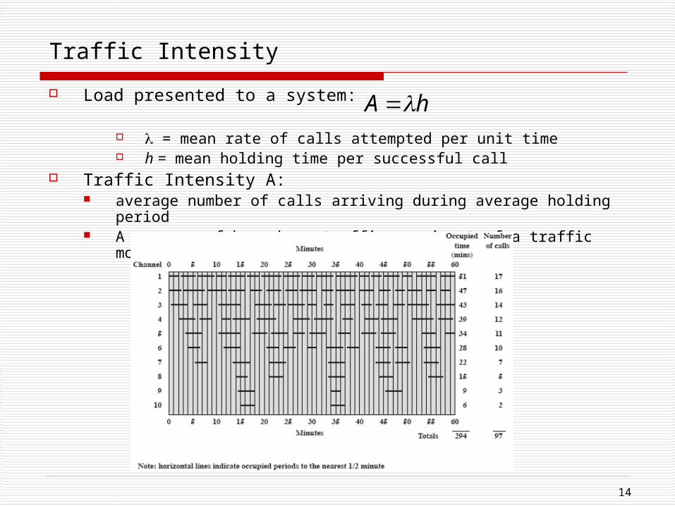
Traffic Intensity
Load presented to a system:
= mean rate of calls attempted per unit time h = mean holding time per successful call
Traffic Intensity A: average number of calls arriving during average holding period A measure of busy-hour traffic, as input of a traffic model
hA
15
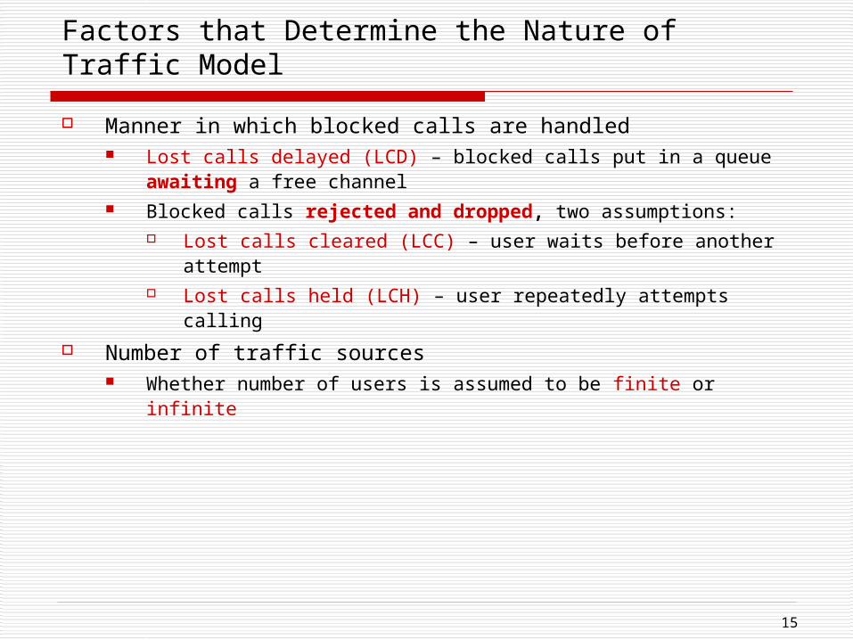
Factors that Determine the Nature of Traffic Model
Manner in which blocked calls are handled Lost calls delayed (LCD) – blocked calls put in a queue awaiting a
free channel Blocked calls rejected and dropped, two assumptions:
Lost calls cleared (LCC) – user waits before another attempt Lost calls held (LCH) – user repeatedly attempts calling
Number of traffic sources Whether number of users is assumed to be finite or infinite
16
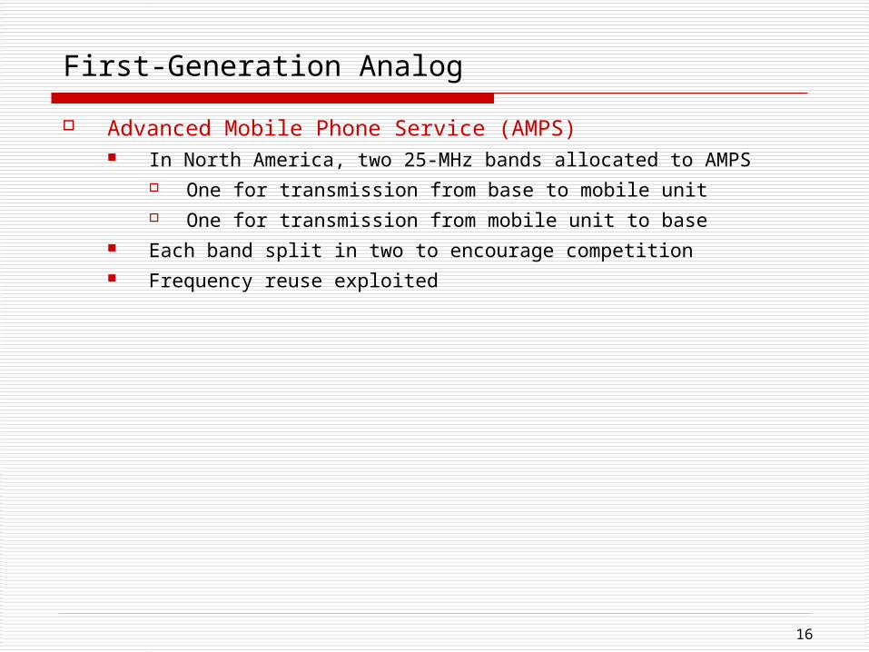
First-Generation Analog
Advanced Mobile Phone Service (AMPS) In North America, two 25-MHz bands allocated to AMPS
One for transmission from base to mobile unit One for transmission from mobile unit to base
Each band split in two to encourage competition Frequency reuse exploited
17
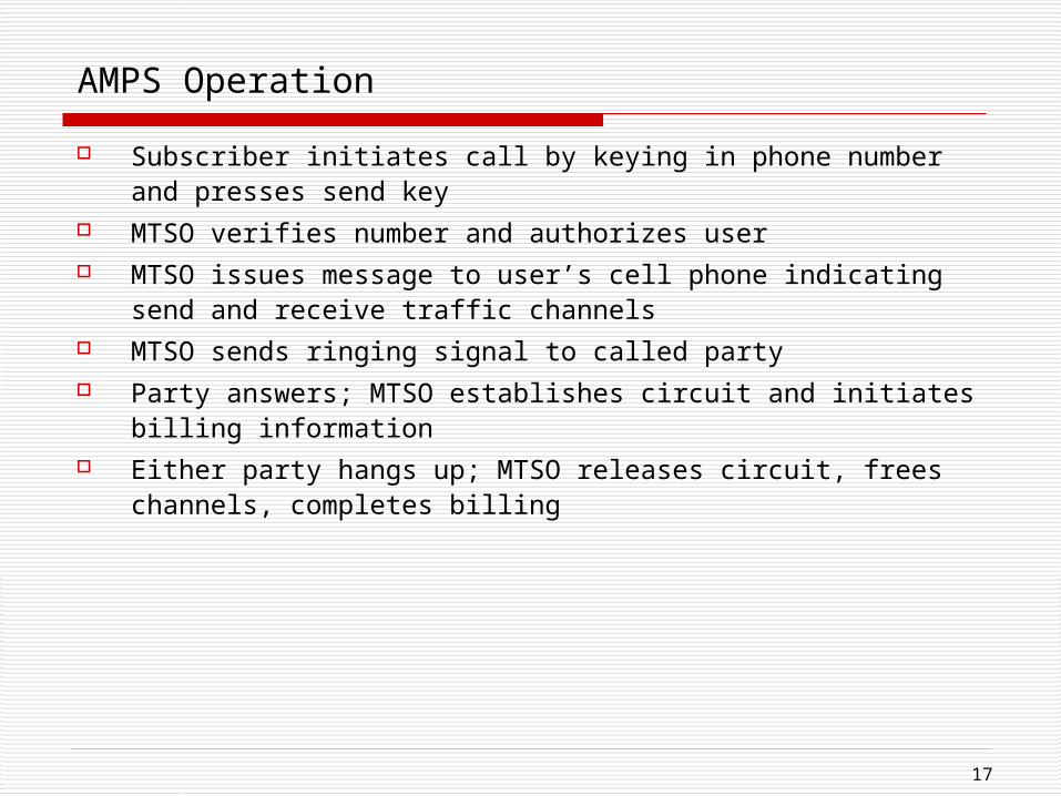
AMPS Operation
Subscriber initiates call by keying in phone number and presses send key
MTSO verifies number and authorizes user MTSO issues message to user’s cell phone indicating send and
receive traffic channels MTSO sends ringing signal to called party Party answers; MTSO establishes circuit and initiates billing
information Either party hangs up; MTSO releases circuit, frees channels,
completes billing
18
Differences Between First and Second Generation Systems
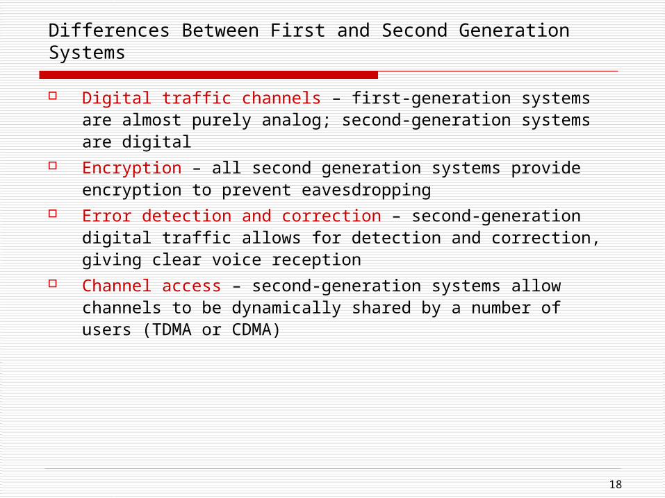
Digital traffic channels – first-generation systems are almost purely analog; second-generation systems are digital
Encryption – all second generation systems provide encryption to prevent eavesdropping
Error detection and correction – second-generation digital traffic allows for detection and correction, giving clear voice reception
Channel access – second-generation systems allow channels to be dynamically shared by a number of users (TDMA or CDMA)
19
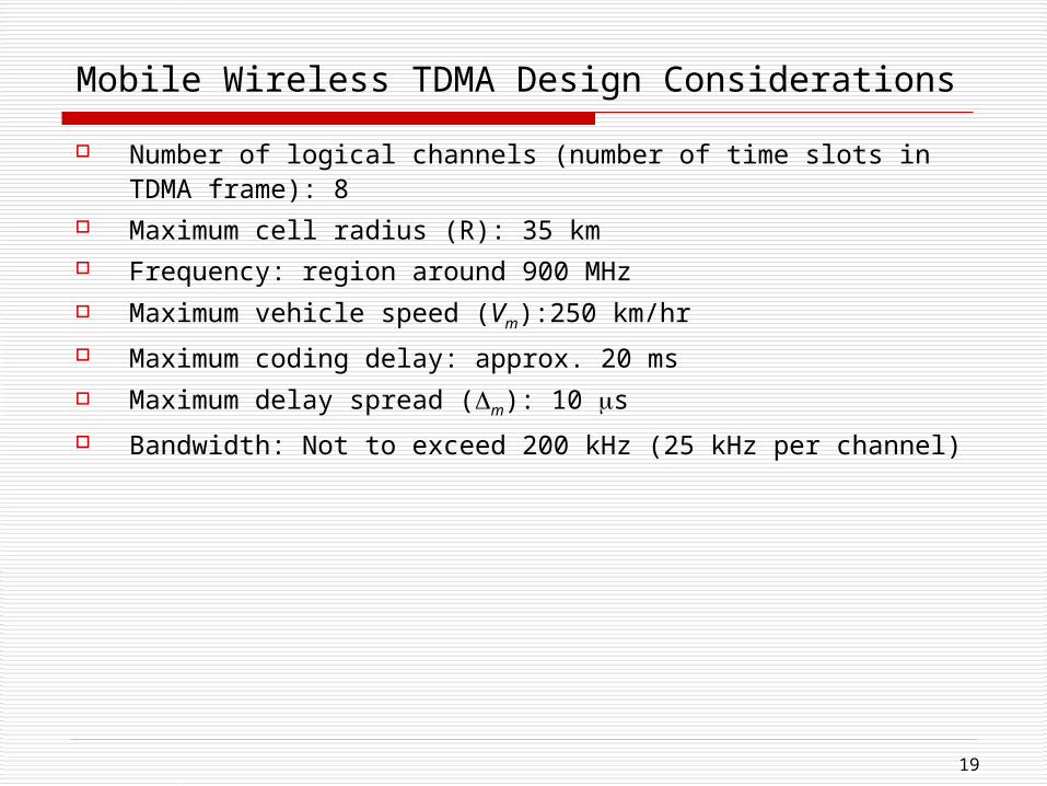
Mobile Wireless TDMA Design Considerations
Number of logical channels (number of time slots in TDMA frame): 8
Maximum cell radius (R): 35 km Frequency: region around 900 MHz Maximum vehicle speed (Vm):250 km/hr
Maximum coding delay: approx. 20 ms Maximum delay spread (m): 10 s
Bandwidth: Not to exceed 200 kHz (25 kHz per channel)
20
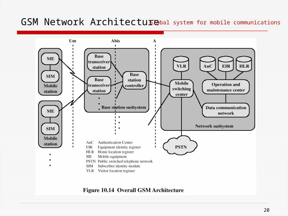
GSM Network Architecture Global system for mobile communications
21
Mobile Station
Mobile station communicates across Um interface (air interface) with base station transceiver in same cell as mobile unit
Mobile equipment (ME) – physical terminal, such as a telephone or PCS ME includes radio transceiver, digital signal processors and subscriber id
entity module (SIM) GSM subscriber units are generic until SIM is inserted
SIMs roam, not necessarily the subscriber devices
22
Base Station Subsystem (BSS)
BSS consists of base station controller and one or more base transceiver stations (BTS)
Each BTS defines a single cell Includes radio antenna, radio transceiver and a link to a base
station controller (BSC)
BSC reserves radio frequencies, manages handoff of mobile unit from one cell to another within BSS, and controls paging
23
Network Subsystem (NS)
NS provides link between cellular network and public switched telecommunications networks Controls handoffs between cells in different BSSs Authenticates users and validates accounts Enables worldwide roaming of mobile users
Central element of NS is the mobile switching center (MSC)

24
Mobile Switching Center (MSC) Databases
Home location register (HLR) database – stores information about each subscriber that belongs to it
Visitor location register (VLR) database – maintains information about subscribers currently physically in the region
Authentication center database (AuC) – used for authentication activities, holds encryption keys
Equipment identity register database (EIR) – keeps track of the type of equipment that exists at the mobile station
25
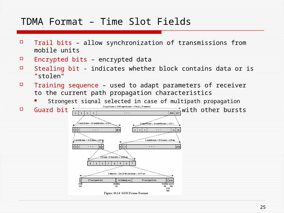
TDMA Format – Time Slot Fields
Trail bits – allow synchronization of transmissions from mobile units Encrypted bits – encrypted data Stealing bit - indicates whether block contains data or is "stolen" Training sequence – used to adapt parameters of receiver to the
current path propagation characteristics Strongest signal selected in case of multipath propagation
Guard bits – used to avoid overlapping with other bursts
26
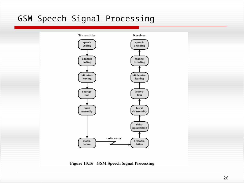
GSM Speech Signal Processing
27
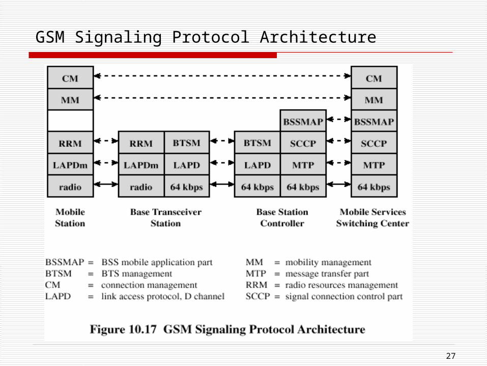
GSM Signaling Protocol Architecture
28
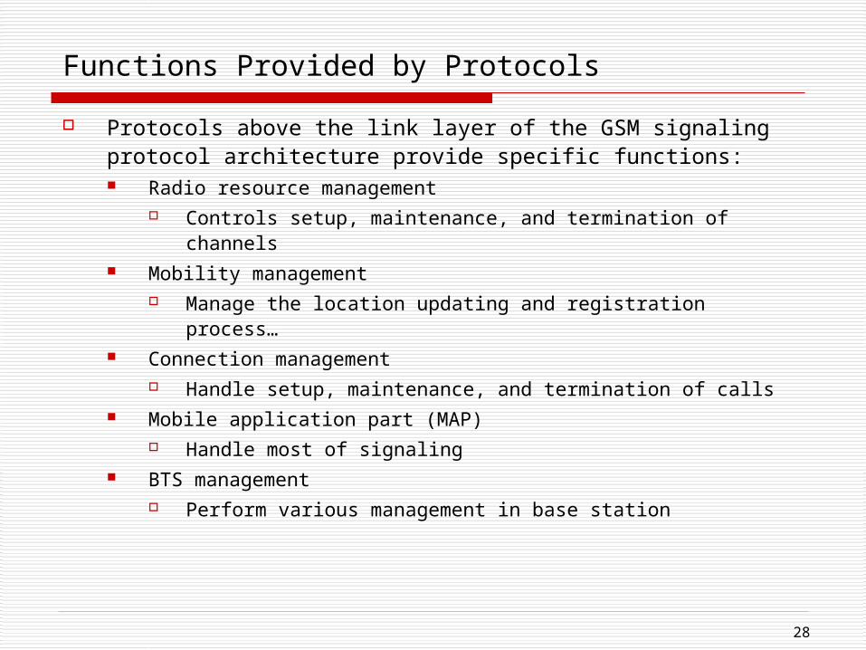
Functions Provided by Protocols
Protocols above the link layer of the GSM signaling protocol architecture provide specific functions: Radio resource management
Controls setup, maintenance, and termination of channels Mobility management
Manage the location updating and registration process… Connection management
Handle setup, maintenance, and termination of calls Mobile application part (MAP)
Handle most of signaling BTS management
Perform various management in base station
29
Advantages of (2G) CDMA Cellular
Frequency diversity – frequency-dependent transmission impairments have less effect on signal
Multipath resistance – chipping codes used for CDMA exhibit low cross correlation and low autocorrelation
Privacy – privacy is inherent since spread spectrum is obtained by use of noise-like signals
Graceful degradation – system only gradually degrades as more users access the system
30
Drawbacks of CDMA Cellular
Self-jamming – arriving transmissions from multiple users not
aligned on chip boundaries unless users are perfectly
synchronized
Near-far problem – signals closer to the receiver are received
with less attenuation than signals farther away
Soft handoff – requires that the mobile acquires the new cell
before it relinquishes the old; this is more complex than hard
handoff used in FDMA and TDMA schemes
31
Mobile Wireless CDMA Design Considerations
RAKE receiver – when multiple versions of a signal arrive more
than one chip interval apart, RAKE receiver attempts to recover
signals from multiple paths and combine them This method achieves better performance than simply recovering
dominant signal and treating remaining signals as noise
Soft Handoff – mobile station temporarily connected to more
than one base station simultaneously
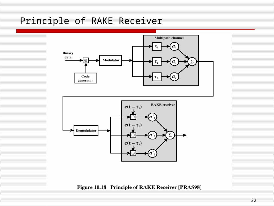
32
Principle of RAKE Receiver
33
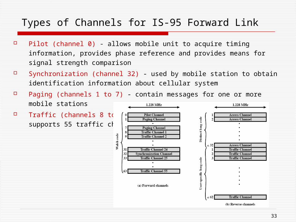
Types of Channels for IS-95 Forward Link
Pilot (channel 0) - allows mobile unit to acquire timing information, provides phase reference and provides means for signal strength comparison
Synchronization (channel 32) - used by mobile station to obtain identification information about cellular system
Paging (channels 1 to 7) - contain messages for one or more mobile stations Traffic (channels 8 to 31 and 33 to 63) – the forward channel supports 55
traffic channels
34
Forward Traffic Channel Processing Steps
Speech is encoded at a rate of 8550 bps Additional bits added for error detection Data transmitted in 20-ms blocks with forward error correction provi
ded by a convolutional encoder Data interleaved in blocks to reduce effects of errors Data bits are scrambled, serving as a privacy mask
Power control information inserted into traffic channel DS-SS function spreads the 19.2 kbps to a rate of 1.2288 Mbps using
one row of 64 x 64 Walsh matrix Digital bit stream modulated onto the carrier using QPSK modulatio
n scheme
35
ITU’s View of Third-Generation Capabilities
Voice quality comparable to the public switched telephone network
144 kbps data rate available to users in high-speed motor vehicles
over large areas
384 kbps available to pedestrians standing or moving slowly over
small areas
Support for 2.048 Mbps for office use
Symmetrical / asymmetrical data transmission rates
Support for both packet switched and circuit switched data services
An adaptive interface to the Internet to reflect efficiently the common
asymmetry between inbound and outbound traffic
More efficient use of the available spectrum in general
Support for a wide variety of mobile equipment
Flexibility to allow the introduction of new services and technologies

36
Alternative Interfaces
37
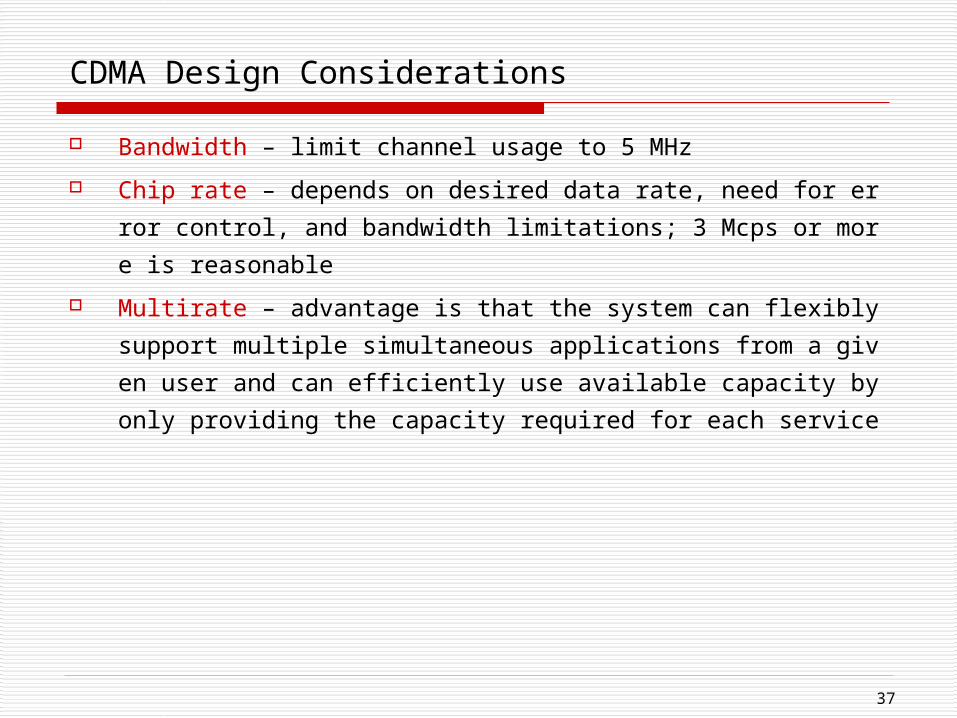
CDMA Design Considerations
Bandwidth – limit channel usage to 5 MHz Chip rate – depends on desired data rate, need for error control, and
bandwidth limitations; 3 Mcps or more is reasonable Multirate – advantage is that the system can flexibly support multipl
e simultaneous applications from a given user and can efficiently use available capacity by only providing the capacity required for each service