Embed Size (px)
Citation preview
1
Novel view synthesis from still pictures
by
Frédéric ABAD
under the supervision of
Olivier FAUGERAS1 Luc ROBERT2 Imad ZOGHLAMI2
1 ROBOTVIS Team INRIA Sophia Antipolis 2 REALVIZ SA
2
Novel view synthesis
Given data: Few reference photographs Reference camera calibration
Objective: Photo-realistic image generation Free virtual camera motion In particular: correct handling of
parallax and image resolution
3
Novel view synthesis
Usual approaches: Model-based rendering
(light simulation with mathematical models)
Image-based rendering(image interpolation)
Our approach: Hybrid image-model based rendering
(texture mapping)

4
Our approach
Based on a hybrid scene representation• Rough 3D model + few images (reference images and
masks)• Layer factorization
Rendering engine (main processing step)• View-dependent texture mapping• Double layered-structure
Refinement step (post-processing step)• Rendering errors occur when the 3D model is too rough
Mask extraction (pre-processing step)• Segmentation of the layers in the reference images

5
Our approach
Hybrid scene representation
Rendering engine (main processing step)
Refinement step (post-processing step)
Mask extraction (pre-processing step)
6
Our approach
Hybrid scene representation
Rendering engine (main processing step)
Refinement step (post-processing step)
Mask extraction (pre-processing step)
7
Scene representation
Hybrid representation:
Few reference images
Rough 3D model (built by image-based modeling)
3D structure decomposed into layers
Binary layer masks extracted from the reference images
8
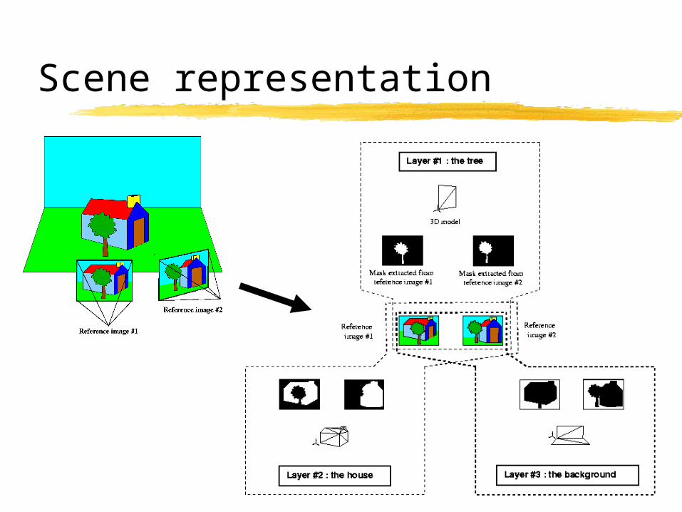
Scene representation
9
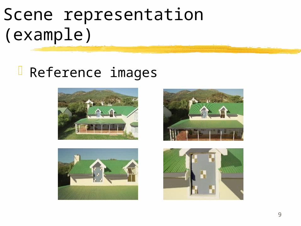
Scene representation (example)
Reference images

10
Scene representation (example)
3D model
11
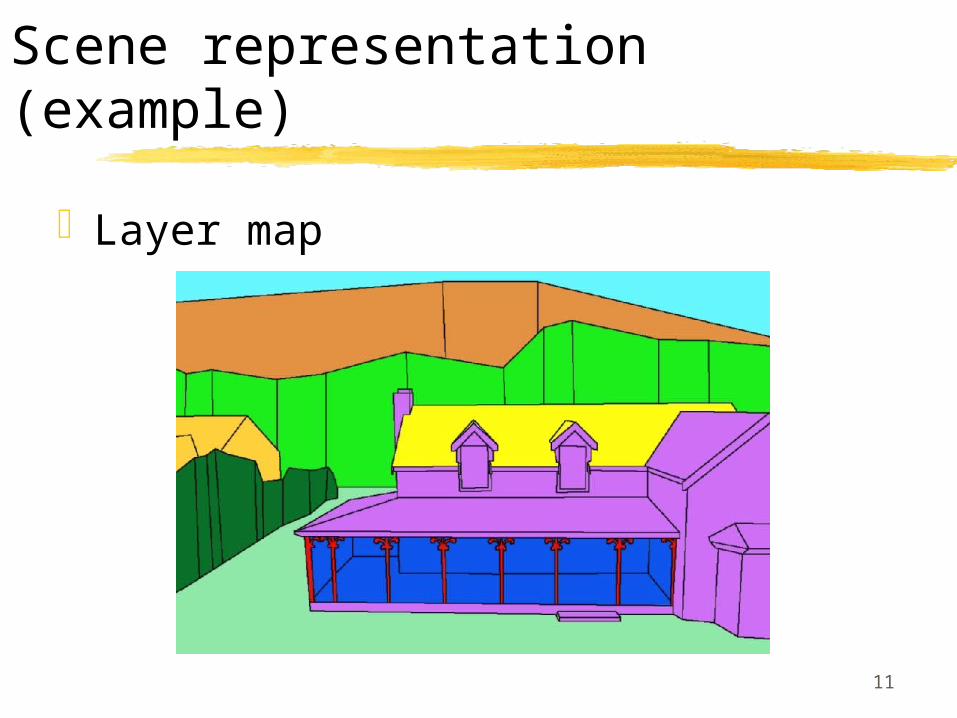
Scene representation (example)
Layer map

12
Scene representation (example)
Masks extracted from reference image #1

13
Our approach
Hybrid scene representation
Rendering engine (main processing step)
Refinement step (post-processing step)
Mask extraction (pre-processing step)

14
Our approach
Hybrid scene representation
Rendering engine (main processing step)
Refinement step (post-processing step)
Mask extraction (pre-processing step)
15
Rendering engine
View-dependent texture mapping [Debevec:96]
• Efficient combination of the different reference images with respect to the virtual viewpoint.
• Optimal image resolution
Double layered-structure, three steps:• Independant rendering of each geometric layer with the
best 3 reference textures• Intra-layer compositing (for VDTM)• Inter-layer compositing (for occlusion processing)
16
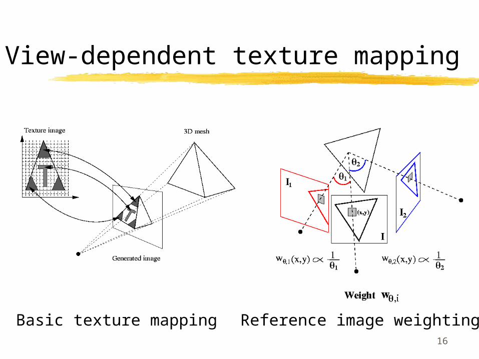
View-dependent texture mapping
Basic texture mapping Reference image weighting
17
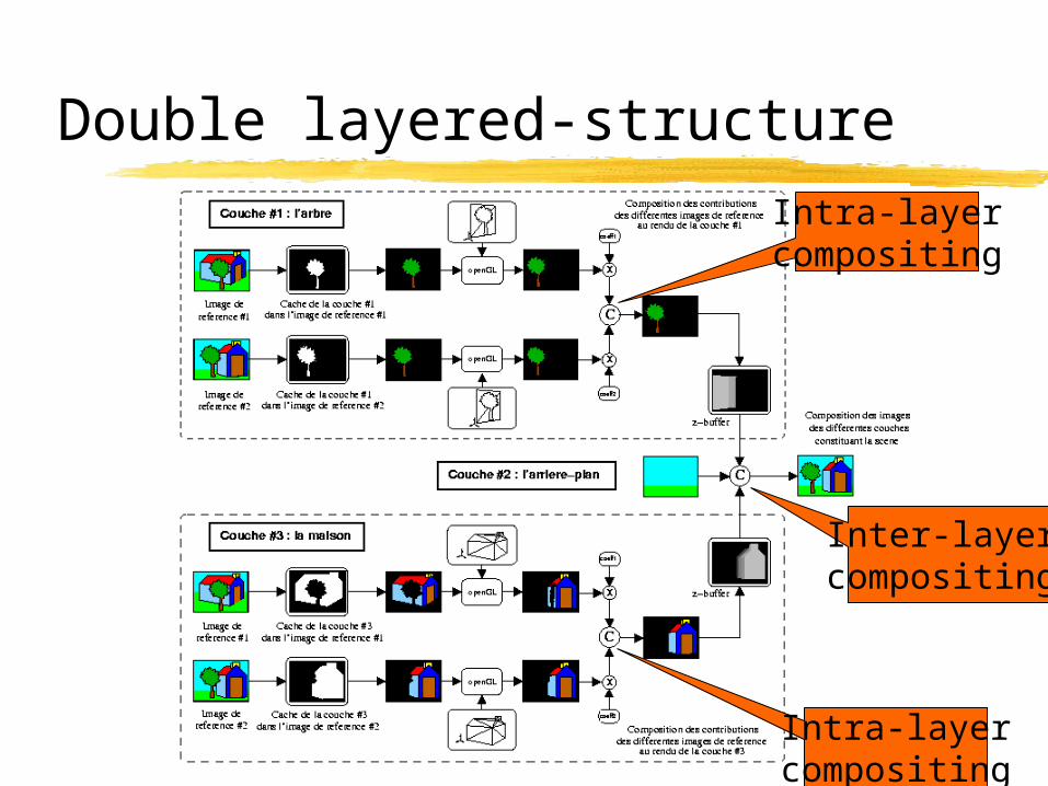
Double layered-structure
Inter-layer compositing
Intra-layercompositing
Intra-layercompositing
18
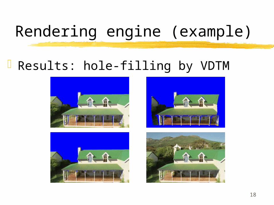
Rendering engine (example)
Results: hole-filling by VDTM
19
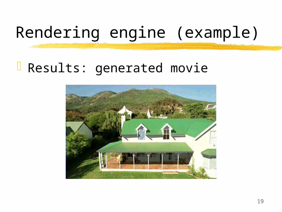
Rendering engine (example)
Results: generated movie
20
Our approach
Hybrid scene representation
Rendering engine (main processing step)
Refinement step (post-processing step)
Mask extraction (pre-processing step)

21
Our approach
Hybrid scene representation
Rendering engine (main processing step)
Refinement step (post-processing step)
Mask extraction (pre-processing step)
22
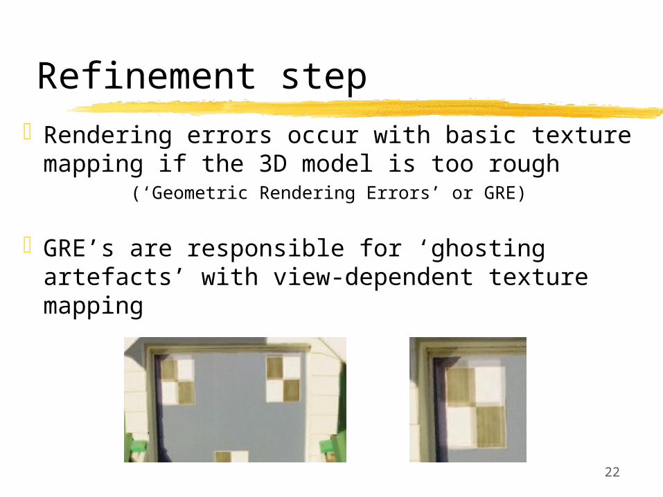
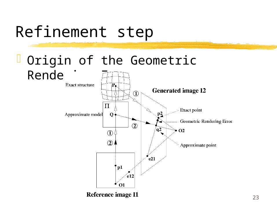
Refinement stepRendering errors occur with basic texture
mapping if the 3D model is too rough(‘Geometric Rendering Errors’ or GRE)
GRE’s are responsible for ‘ghosting artefacts’ with view-dependent texture mapping
23
Refinement step
Origin of the Geometric Rendering Errors

24
Refinement step
Origin of the ghosting artefacts

25
Refinement stepOur correcting approach:1) Detect GRE’s in auxiliary reference images2) Propagate them in new generated images3) Correct them by image morphing
26
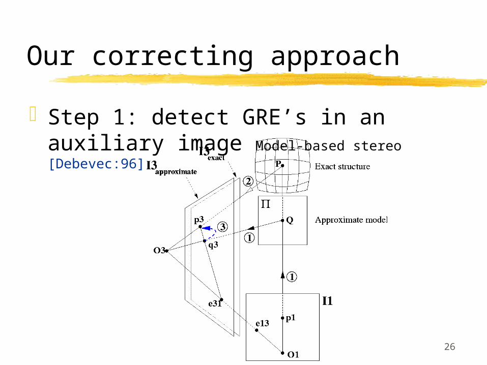
Our correcting approach
Step 1: detect GRE’s in an auxiliary image Model-based stereo [Debevec:96]
27
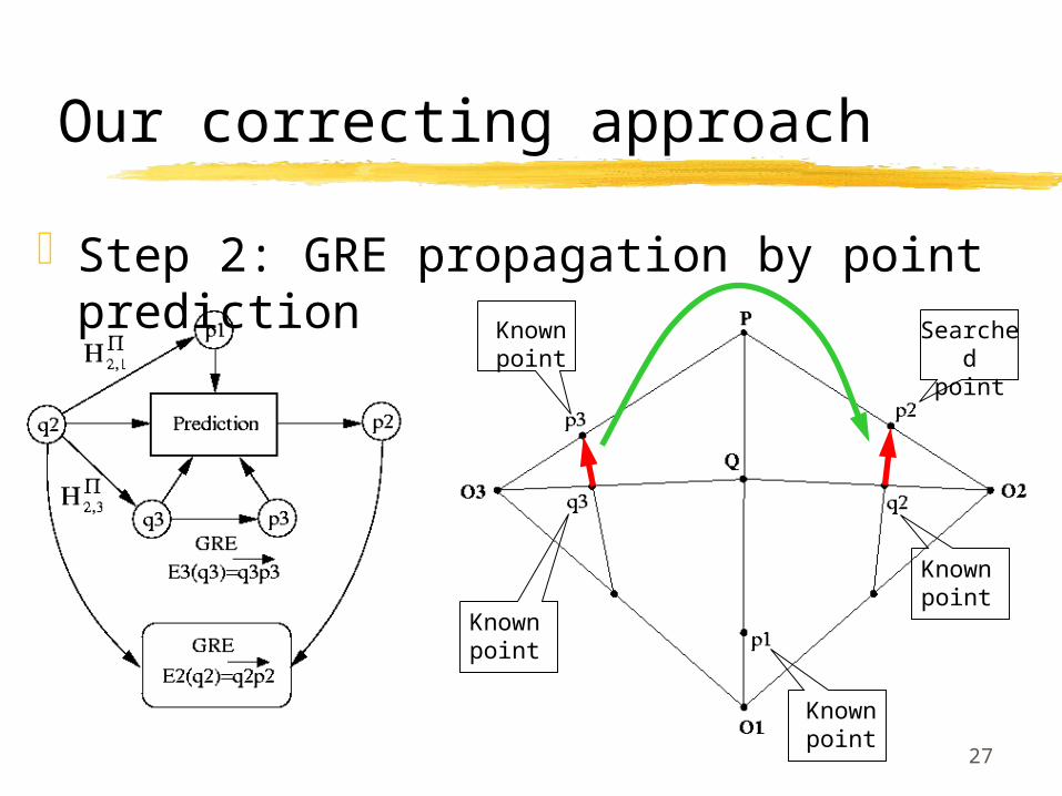
Our correcting approach
Step 2: GRE propagation by point prediction
Knownpoint
Knownpoint
Knownpoint
Knownpoint
Searchedpoint
28
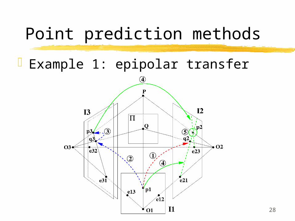
Point prediction methods
Example 1: epipolar transfer
29
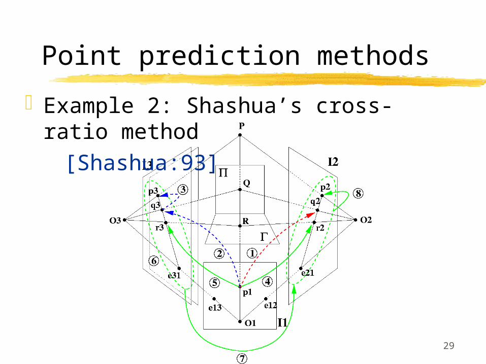
Point prediction methods
Example 2: Shashua’s cross-ratio method
[Shashua:93]
30
Point prediction methods
Other point prediction methods:
3D point reconstruction and projection Trifocal transfer Compact cross-ratio method Irani’s parallax-based multi-frame
rigidity constraint method

31
Our correcting approach
Step 3: correct the GRE’s by image morphing

32
Our correcting approach
Experimental comparison of point prediction methods: Epipolar transfer: simplest implementation
but imprecise and instable close to the trifocal plane
Irani’s approach: complex, imprecise and instable method
Cross-ratio approaches: simple, precise and stable methods

33
Our correcting approach
Experimental application to deghosting
34
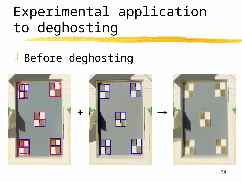
Experimental application to deghosting
Before deghosting
+
35
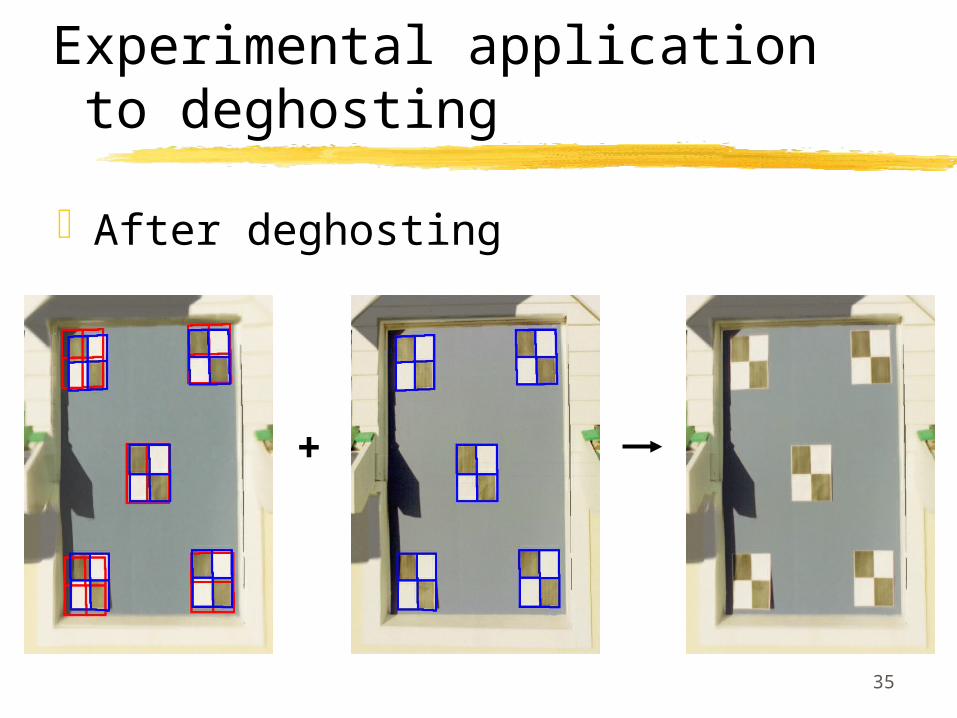
Experimental application to deghosting
After deghosting
+

36
Experimental application to deghosting
Comparison before/after
Before deghosting After deghosting

37
Our approach
Hybrid scene representation
Rendering engine (main processing step)
Refinement step (post-processing step)
Mask extraction (pre-processing step)
38
Our approach
Hybrid scene representation
Rendering engine (main processing step)
Refinement step (post-processing step)
Mask extraction (pre-processing step)
39
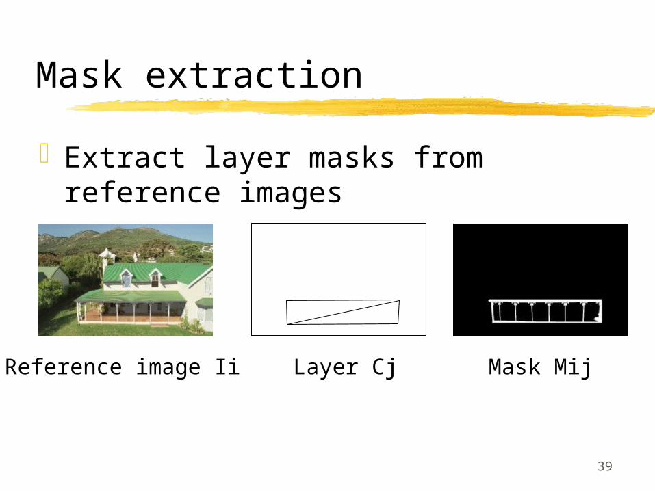
Mask extraction
Extract layer masks from reference images
Reference image Ii Layer Cj Mask Mij

40
Mask extraction
Region-based image segmentation: pixel labelling by energy
minimization
Energies
Optimization techniques

41
Mask extraction
Region-based image segmentation: pixel labelling by energy
minimization
Energies
Optimization techniques
42
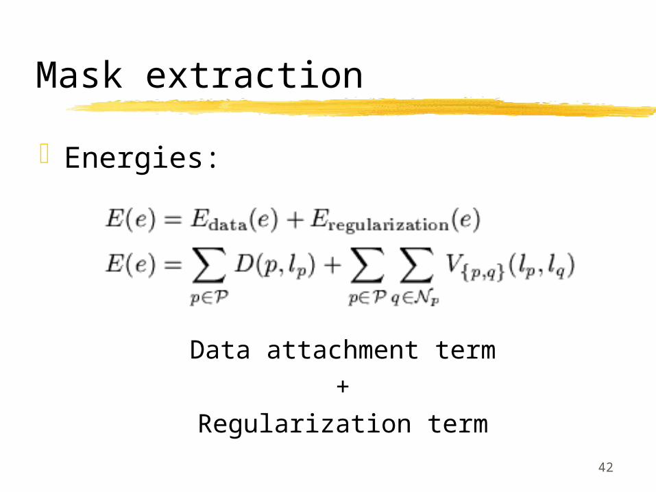
Mask extraction
Energies:
Data attachment term+
Regularization term
43
Energies
Data attachment term
Ensures the adaptation of the labelling to the observed data in the image
Inverse of the labelling likelihood

44
Data attachment term
Usual segmentation criteria: Luminance: luma-key Color: chroma-key Texture: texture-key
Emphasis on a new geometric
criterion: planar-key
45
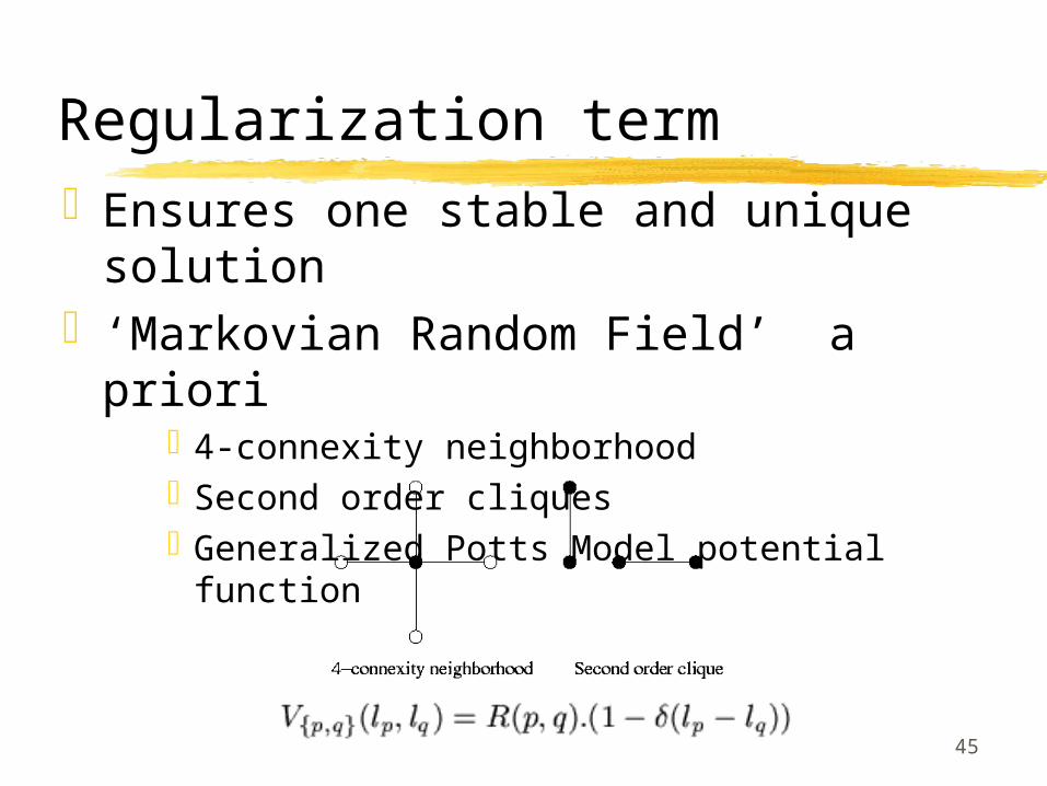
Regularization termEnsures one stable and unique
solution‘Markovian Random Field’ a priori
4-connexity neighborhoodSecond order cliquesGeneralized Potts Model potential function
46
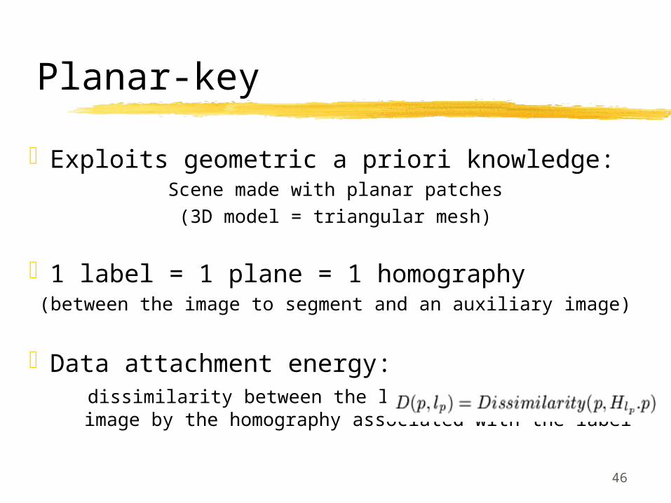
Exploits geometric a priori knowledge:Scene made with planar patches
(3D model = triangular mesh)
1 label = 1 plane = 1 homography(between the image to segment and an auxiliary image)
Data attachment energy: dissimilarity between the labelled pixel and its
image by the homography associated with the label
Planar-key
47
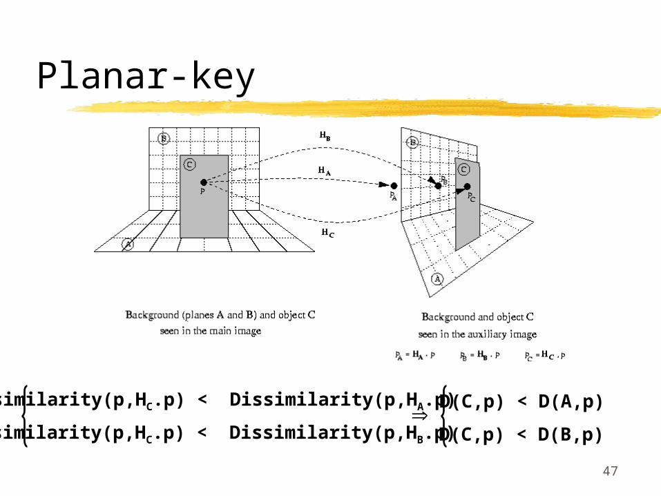
Planar-key
Dissimilarity(p,HC.p) < Dissimilarity(p,HA.p)
Dissimilarity(p,HC.p) < Dissimilarity(p,HB.p)
D(C,p) < D(A,p)
D(C,p) < D(B,p)
48
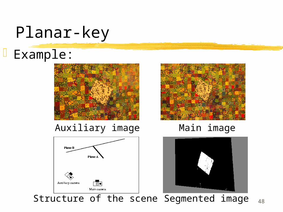
Planar-keyExample:
Auxiliary image Main image
Segmented imageStructure of the scene

49
Planar-key
Technique more complex than it seems: Dissimilarity measures Photometric discrepancy robustness Geometric inaccuracy robustness Occlusion shadow error management
50
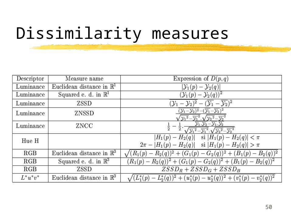
Dissimilarity measures
51
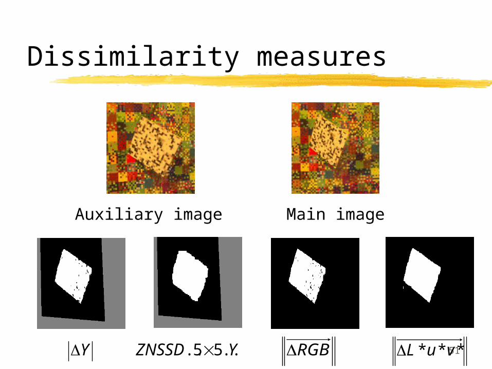
Dissimilarity measures
*** vuLRGBY YZNSSD ..55..
Main imageAuxiliary image

52
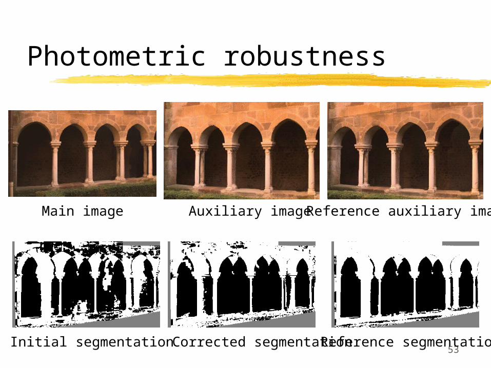
Photometric robustness
Problems when the main and auxiliary Camera Response Functions do not match.
Proposed solution: Piece-wise luminance histogram correction Affine transformation included in the
dissimilarity computation
53
Photometric robustness
Main image Auxiliary image Reference auxiliary image
Initial segmentation Corrected segmentation Reference segmentation

54
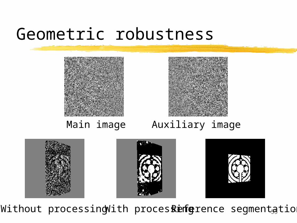
Geometric robustness
Problems when homographies are not accurate
Proposed solution: best-match point selection
55
Geometric robustness
Main image Auxiliary image
Reference segmentationWithout processing With processing
56
Occlusion shadow errors
Origin of the occlusion shadow errors:
pixels corresponding to occluded 3D points in auxiliary images
planar-key no longer valid potential labelling errors
(foreground label instead of background label)
57
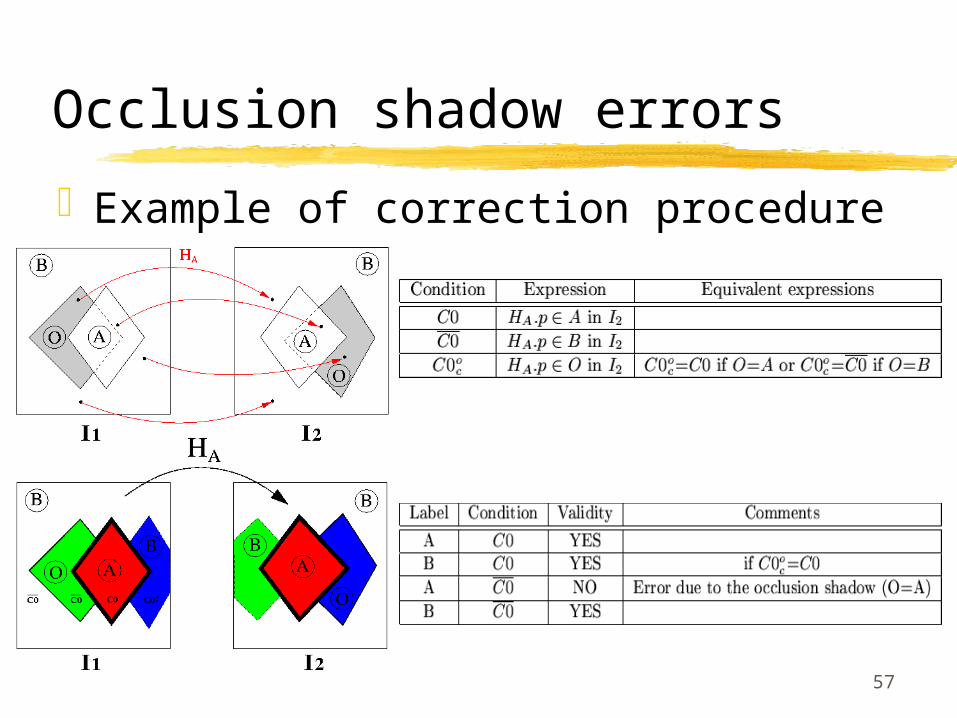
Occlusion shadow errors
Example of correction procedure
58
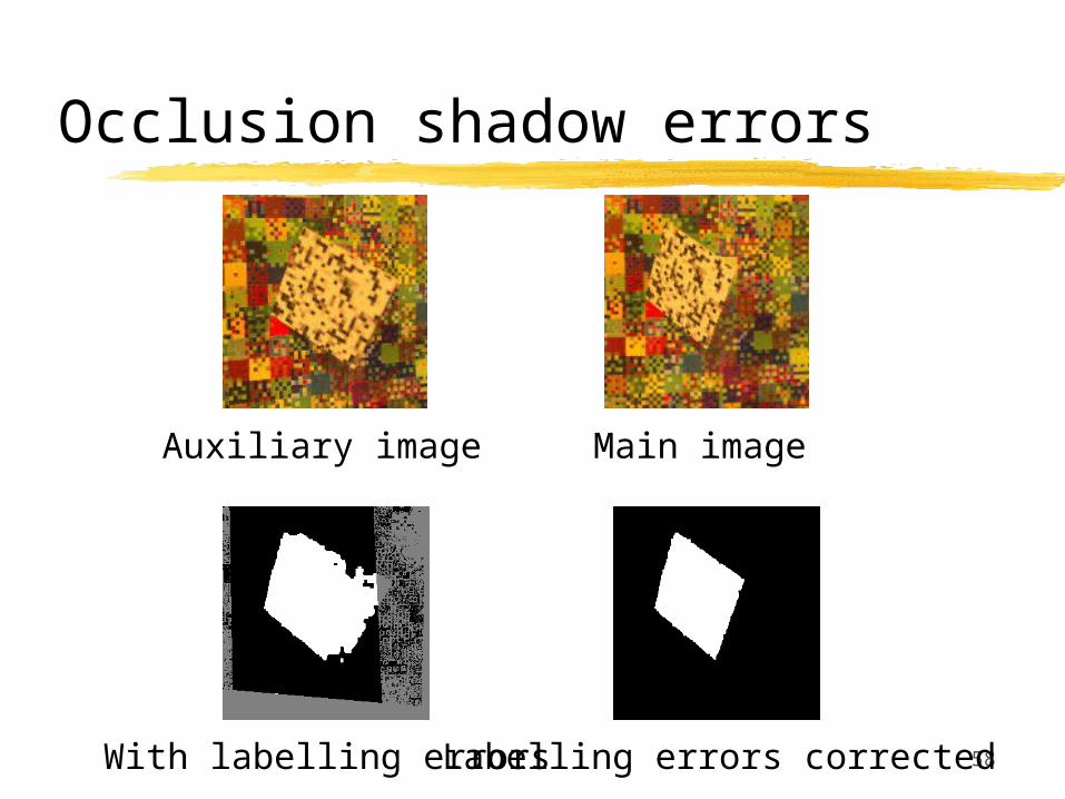
Occlusion shadow errors
Auxiliary image Main image
With labelling errors Labelling errors corrected
59
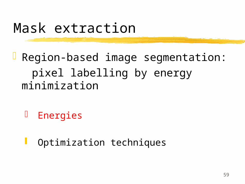
Mask extraction
Region-based image segmentation: pixel labelling by energy
minimization
Energies
Optimization techniques
60
Mask extraction
Region-based image segmentation: pixel labelling by energy
minimization
Energies
Optimization techniques
61
Optimization techniques
Usual approaches Deterministic (snakes) Stochastic (simulated annealing)
New approach: Graph-based techniques: graph-cuts
[Boykov-etal:99]
62
Optimization techniques
Graph-cuts: Well-adapted to our problem (MAP computation) Efficient (global minimum for 2-label problem) Low complexity algorithms Many implementations but no practical study
Complete study of the graph-cut implementations

63
Graph-cuts
Minimal energy = minimal cut = optimal labelling
Minimal cut = maximal flow (maxflow-mincut theorem [Ford-Fulkerson:56])

64
Graph-cuts
Generic max-flow algorithms:

65
Graph-cuts
Best implementations:
Shortest augmenting path with
Optimized stopping conditionGeometric optimization
FIFO preflow-push with
Optimized FIFO emptying condition(no efficient geometric optimization)

66
Graph-cuts
Practical implementation speeding-up
67
Conclusion
Contributions: Complete processing chain:
Pre-processing step: new mask extraction technique
(planar-key + graph-cut techniques)
Main processing step: efficient and open rendering framework
(layered structure + view-dependent texture mapping)
Post-processing step: original refinement approach(Geometric Rendering Errors propagation + deghosting)

68
Conclusion
Future work: Mask extraction:
• Other regularization a priori (Chien model)• Sub-pixel segmentation (partial transparency)
Rendering step:• Rendering speed (interactive frame-rate)• Automatization (weighting and ordering schemes)
Refinement step:• ‘3D Image Warping’-like refinement equation • Automatization and integration in the rendering
engine