Embed Size (px)
Citation preview
1
Optimal Power Allocation and AP Deployment in Green Wireless Cooperative Communications
Xiaoxia [email protected]
Department of Electrical and Computer EngineeringUniversity of Waterloo
2
Outline
• Introduction
• System Model
• Power Allocation for a Single-User Link
• AP Deployment
• Conclusions and Future Work
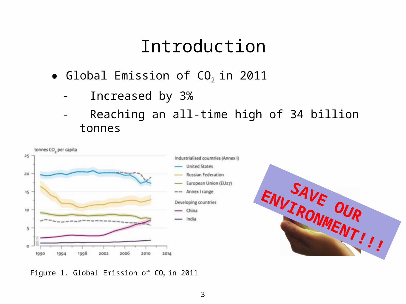
• Global Emission of CO2 in 2011
- Increased by 3%
- Reaching an all-time high of 34 billion tonnes
Figure 1. Global Emission of CO2 in 2011
SAVE OUR
ENVIRONMENT!!!
Introduction
3
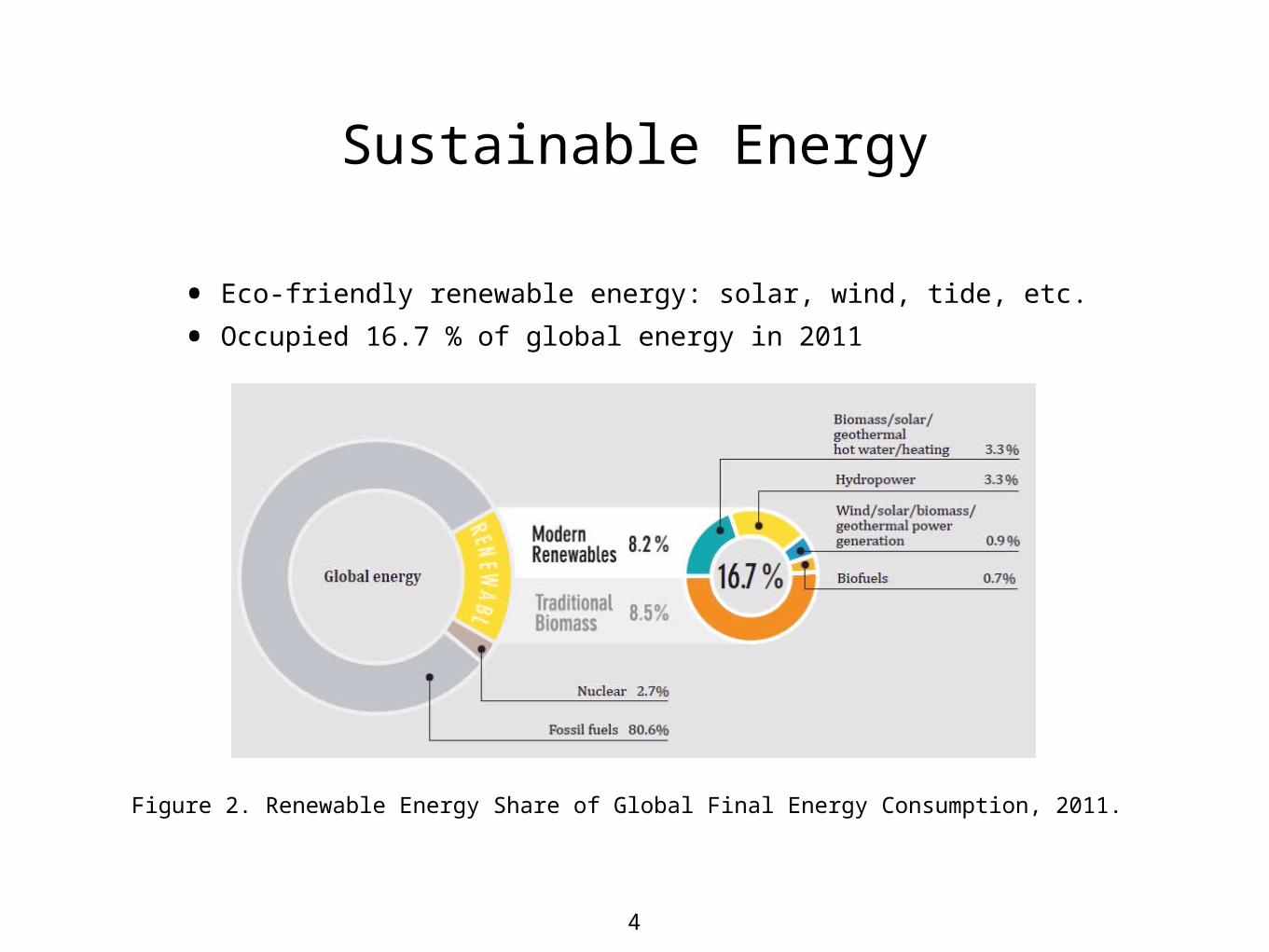
• Eco-friendly renewable energy: solar, wind, tide, etc.
• Occupied 16.7 % of global energy in 2011
Figure 2. Renewable Energy Share of Global Final Energy Consumption, 2011.
Sustainable Energy
4

• In wireless communications
- Up to 90% of power consumption in BSs
- Energy cost is high and increasing
• Green wireless networks: network devices powered by sustainable energy
- Example: Huawei
Solar-powered base stations deployed over 1500 sites in over 30 countries and regionso Operation cost reduced over 60%
o Carbon footprints reduced over 40%
Figure 3. A Green Base Station
Green Technology in Wireless Communications
5

• Characteristics of Sustainable Energy
- Variable or intermittent in its capacity
- Highly dependent on the location and weather
• Fulfillment of users’ QoS demand is challenging.
- Introduction of cooperative communication
- More efficient green wireless network
o Device deployment
o Resource allocation
Motivation
6

In a WLAN network where green APs are deployed, we would like to maximize the overall throughput by jointly allocating transmitting power and deploying the green APs, subject to the harvested energy constraint.
Objective
7

8
Outline
• Introduction
• System Model
• Power Allocation for a Single-User Link
• AP Deployment
• Conclusions and Future Work

9
System Model
• A wireless local area network (WLAN) where a green AP is deployed.
• Nodes could communicate with each other in an ad hoc manner.
• Transmission links are separated by TDMA.
• AP can cooperate with the source nodes to transmit data to the destination.
• n links in total.Figure 4. A green wireless cooperative communication network.
10
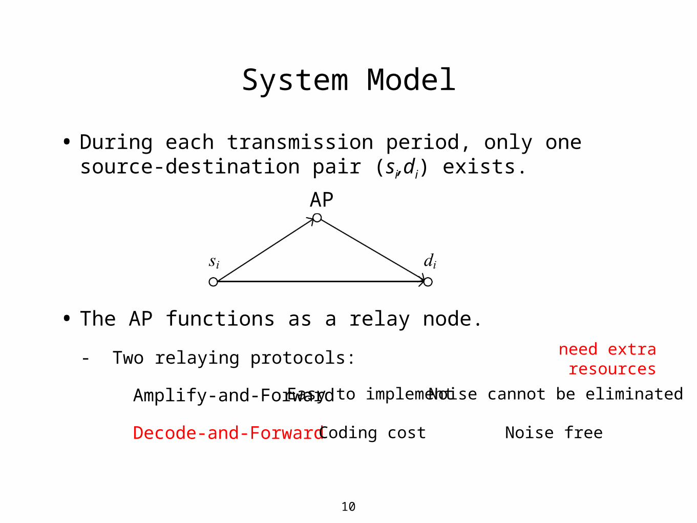
System Model
• During each transmission period, only one source-destination pair (si,di) exists.
AP
• The AP functions as a relay node.
- Two relaying protocols:
Amplify-and-Forward
Decode-and-Forward
Easy to implementNoise cannot be eliminated
Coding cost Noise free
need extra resources
11
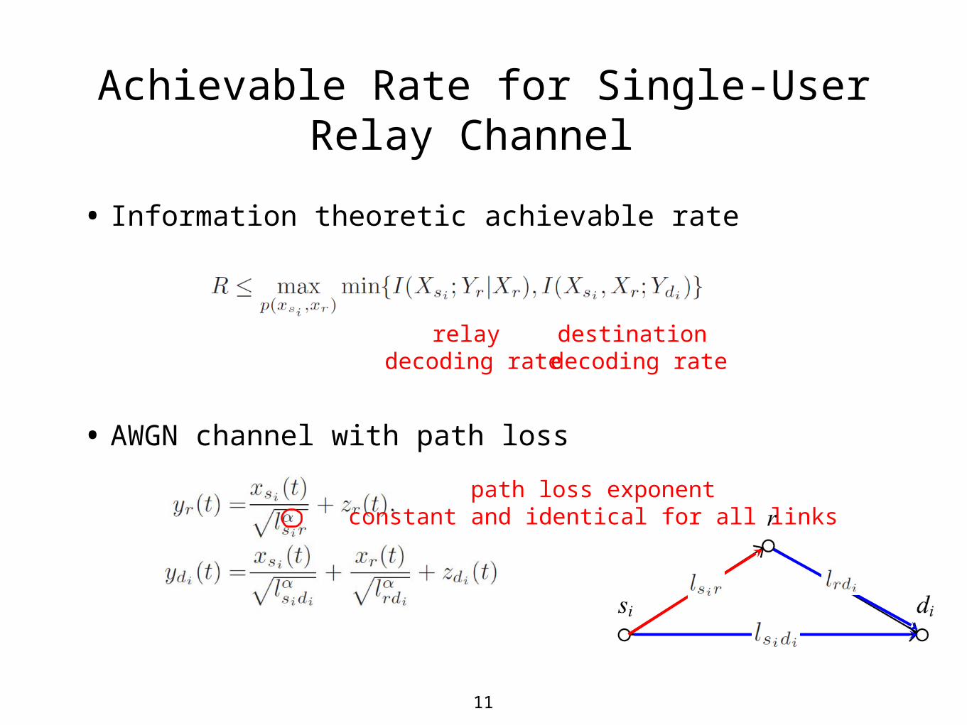
• Information theoretic achievable rate
Achievable Rate for Single-User Relay Channel
relay decoding rate
destination decoding rate
• AWGN channel with path loss
path loss exponentconstant and identical for all links
12
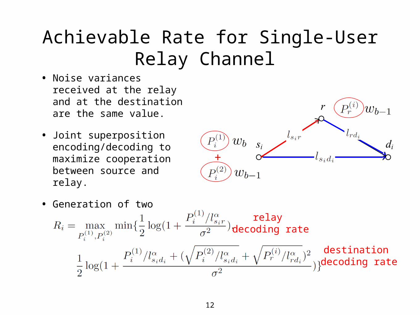
Achievable Rate for Single-User Relay Channel
• Noise variances received at the relay and at the destination are the same value.
• Joint superposition encoding/decoding to maximize cooperation between source and relay.
• Generation of two codes.
+
relay decoding rate
destination decoding rate
13
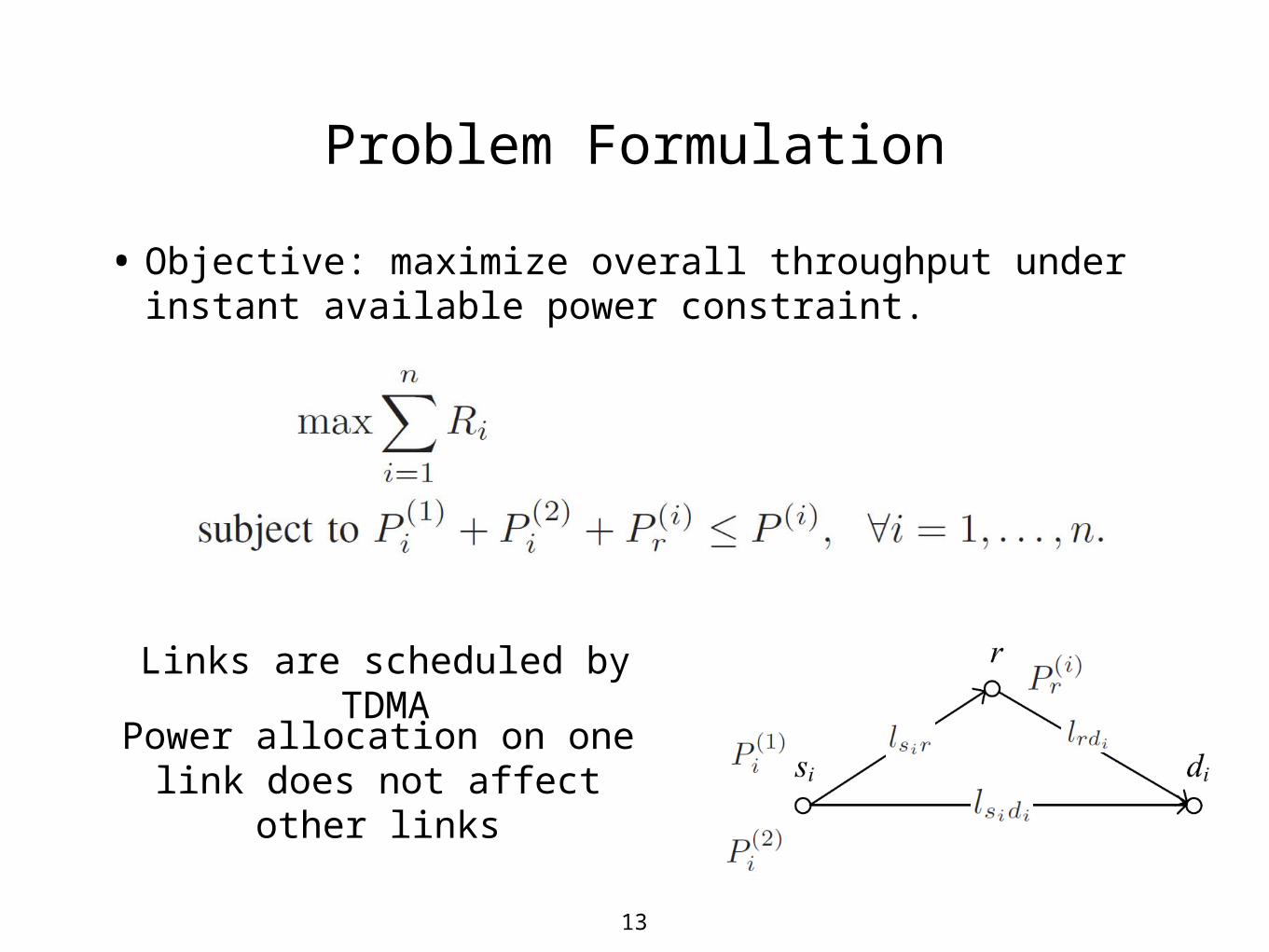
Problem Formulation
• Objective: maximize overall throughput under instant available power constraint.
Links are scheduled by TDMA
Power allocation on one link does not affect other links
14
Outline
• Introduction
• System Model
• Power Allocation for a Single-User Link
• AP Deployment
• Conclusions and Future Work
15
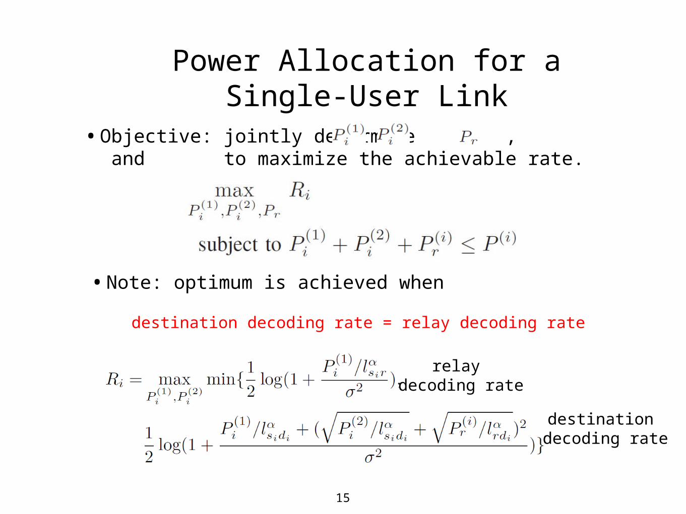
•Objective: jointly determine , and to maximize the achievable rate.
Power Allocation for a Single-User Link
• Note: optimum is achieved when
destination decoding rate = relay decoding rate
relay decoding rate
destination decoding rate

16
•Destination decoding rate is the bottleneck.
•Increase and reduce to balance.
•Coherent transmission.
Synchronous Case
relay decoding rate
destination decoding rate
Optimal power allocation is:
Largest achievable rate is:

17
•Relay decoding rate is the bottleneck.
•Source will set and .
•Independent transmission.
Asynchronous Case
Optimal power allocation is:
Largest achievable rate is:
relay decoding rate
destination decoding rate
18
Outline
• Introduction
• System Model
• Power Allocation for a Single-User Link
• AP Deployment
• Conclusions and Future Work
19
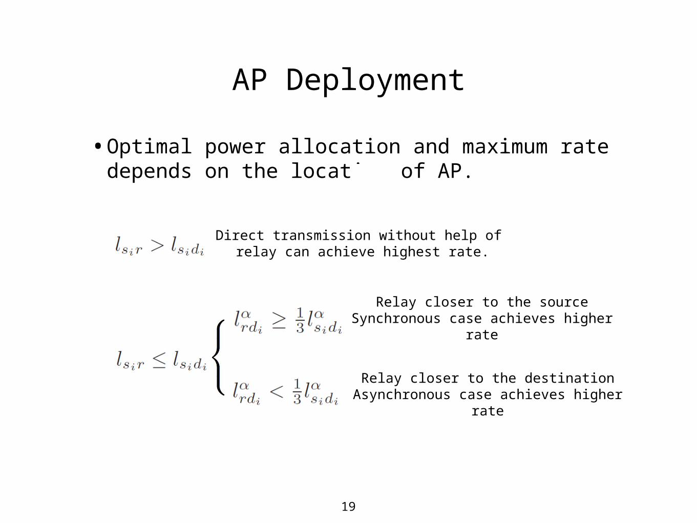
•Optimal power allocation and maximum rate depends on the location of AP.
AP Deployment
Direct transmission without help of relay can achieve highest rate.
Relay closer to the sourceSynchronous case achieves higher rate
Relay closer to the destinationAsynchronous case achieves higher rate
20
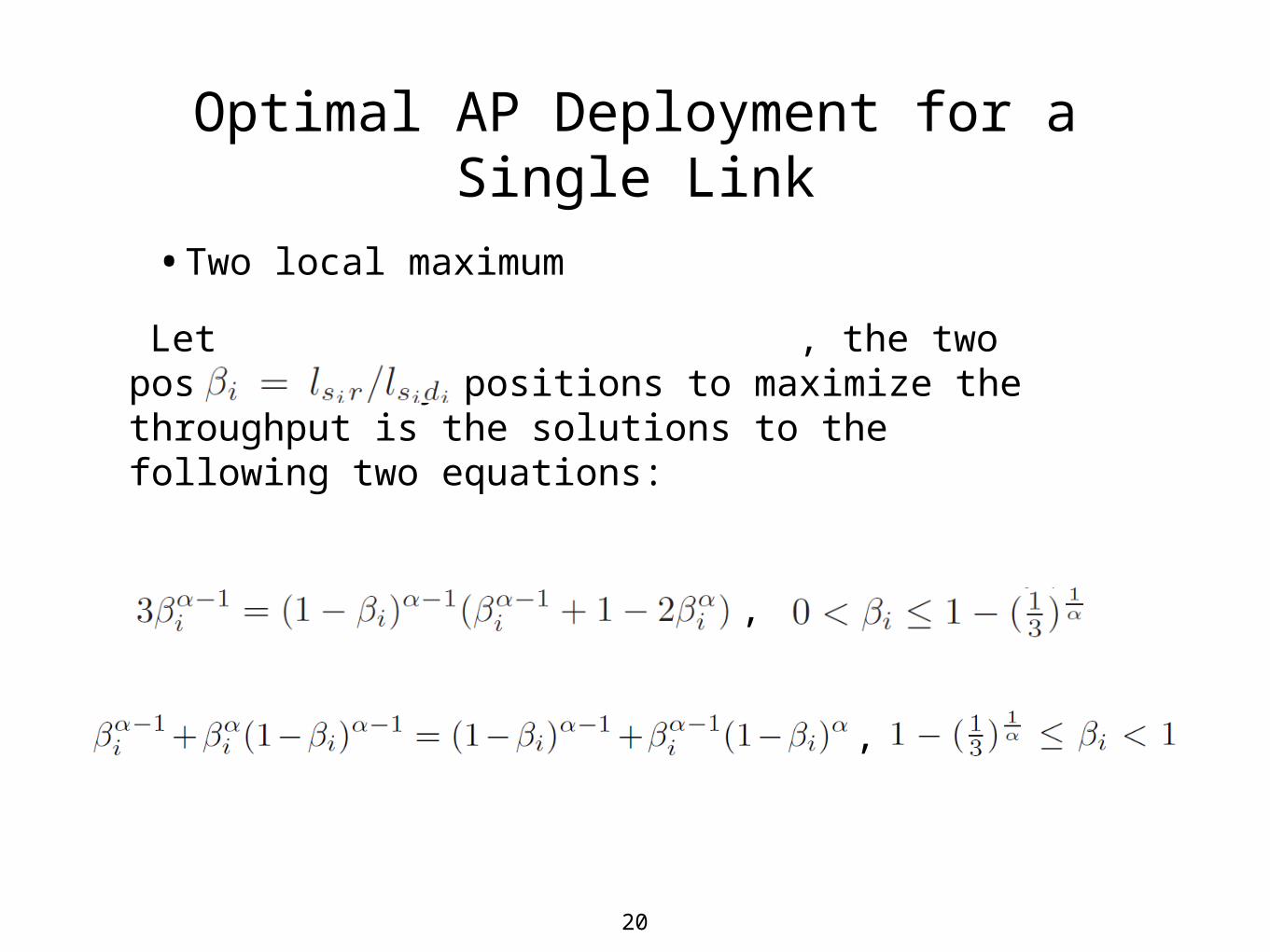
•Two local maximum
Optimal AP Deployment for a Single Link
Let , the two possible relay positions to maximize the throughput is the solutions to the following two equations:
,
,

21
•Sustainable energy can only be exploited in some specific locations due to the availability and neighboring environment.
•Several candidate AP locations are considered.
•The optimal location can be decided based on the overall throughput which is calculated by
Optimal AP Deployment
22
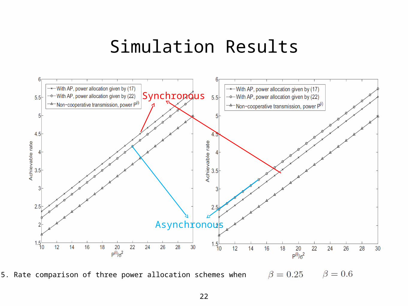
Simulation Results
Figure 5. Rate comparison of three power allocation schemes when and .
Synchronous
Asynchronous

23
Simulation Results
Figure 6. Achievable rate of a single user link with different AP locations.
24
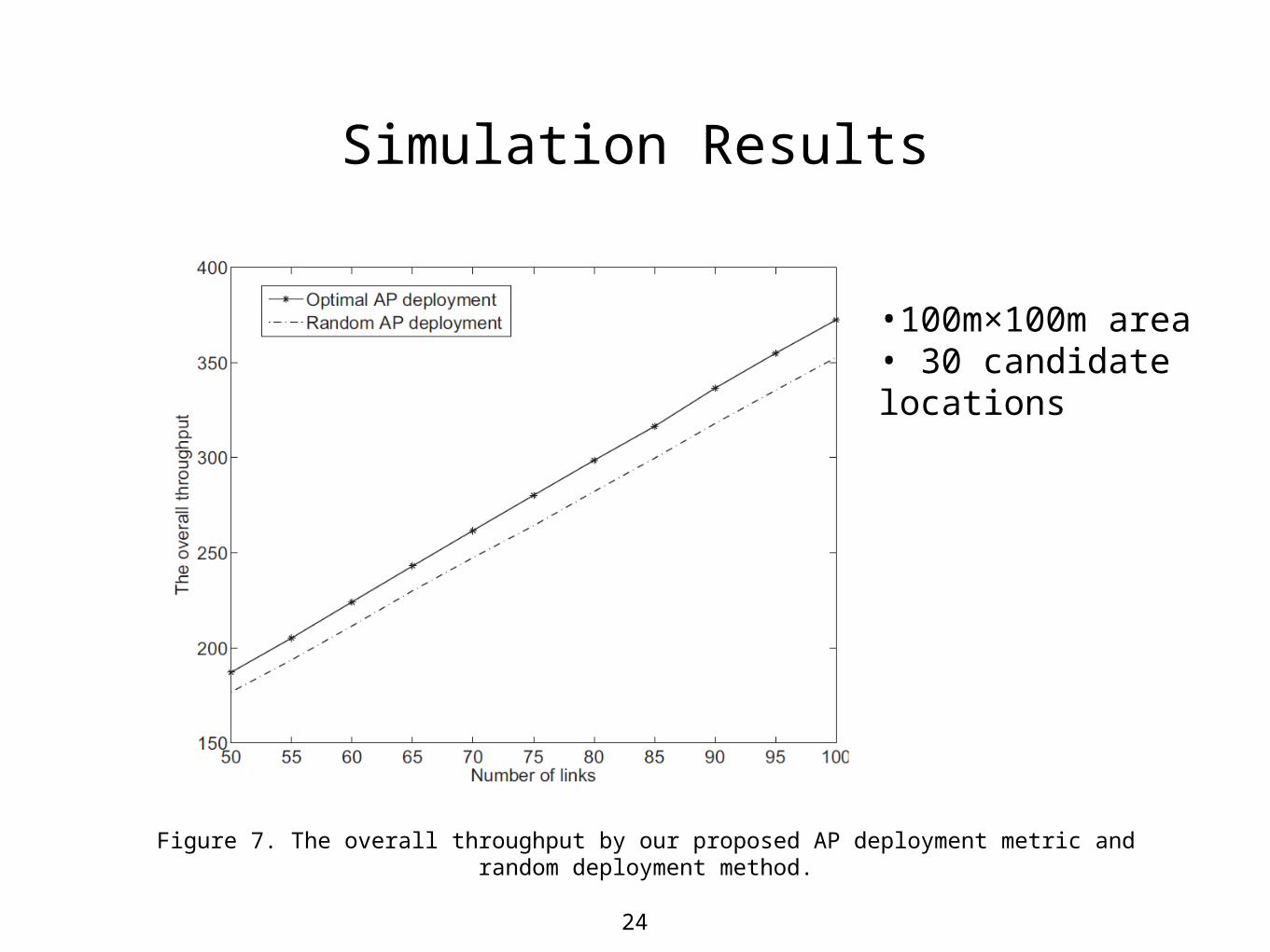
Simulation Results
Figure 7. The overall throughput by our proposed AP deployment metric and random deployment method.
•100m×100m area• 30 candidate locations
25
Outline
• Introduction
• System Model
• Power Allocation for a Single-User Link
• AP Deployment
• Conclusions and Future Work
26
Conclusions and Future Work
In this paper, a single-user channel achievable rate maximization problem is formulated and the optimal power allocation scheme is derived.
A throughput upper bound of each single-user channel is attained and the optimal AP deployment is provided.
In the future, we will consider the dynamic charging and discharging buffer in the AP.

27
Thanks!