Embed Size (px)
Citation preview

1
Pre–Capture Privacy for Small Vision SensorsFrancesco Pittaluga, Member, IEEE, and Sanjeev J Koppal, Member, IEEE,
Abstract—The next wave of micro and nano devices will create a world with trillions of small networked cameras. This will lead toincreased concerns about privacy and security. Most privacy preserving algorithms for computer vision are applied after image/videodata has been captured. We propose to use privacy preserving optics that filter or block sensitive information directly from the incidentlight-field before sensor measurements are made, adding a new layer of privacy. In addition to balancing the privacy and utility of thecaptured data, we address trade-offs unique to miniature vision sensors, such as achieving high-quality field-of-view and resolutionwithin the constraints of mass and volume. Our privacy preserving optics enable applications such as depth sensing, full-body motiontracking, people counting, blob detection and privacy preserving face recognition. While we demonstrate applications on macro-scaledevices (smartphones, webcams, etc.) our theory has impact for smaller devices.
Index Terms—Computer Vision, Privacy.
F
1 INTRODUCTION
Our world is bursting with ubiquitous, networked sensors.Even so, a new wave of sensing that dwarfs current sensornetworks is on the horizon. These are miniature platforms, withfeature sizes less than 1mm, that will appear in micro air ve-hicle swarms, intelligent environments, body and geographicalarea networks. Equipping these platforms with computer visioncapabilities could impact security, search and rescue, agriculture,environmental monitoring, exploration, health, energy, and more.
Yet, achieving computer vision at extremely small scales stillfaces two challenges. First, the power and mass constraints areso severe that full-resolution imaging, along with post-captureprocessing with convolutions, matrix inversions, and the like,are simply too restrictive. Second, the privacy implications ofreleasing trillions of networked, tiny cameras into the world wouldmean that there would likely be significant societal pushback andlegal restrictions.
In this paper, we propose a new framework to achieve bothpower efficiency and privacy preservation for vision on smalldevices. We build novel fixed and programmable optical designsthat filter incident illumination from the scene, before imagecapture. This allows us to attenuate sensitive information whilecapturing exactly the portion of the signal that is relevant to aparticular vision task. In this sense, we seek to generalize theidea of privacy preserving optics beyond specialized efforts. Wedemonstrate privacy preserving optics that enable accurate depthsensing, full-body motion tracking, multiple people tracking, blobdetection and face recognition.
Our optical designs filter light before image capture andrepresent a new axis of privacy vision research that complementsexisting “post image capture” based approaches to privacy preser-vation. Like these other approaches, we seek to balance the utilityand privacy of the data. For miniature sensors, we must alsobalance the performance and privacy guarantees of the systemwith sensor characteristics such as mass/volume, field-of-view andresolution. In this paper, we show applications on macro-scale
• F. Pittaluga and S. J. Koppal are with the Department of Electrical andComputer Engineering, University of Florida, Gainesville, FL, 32611.E-mail: [email protected] and [email protected]
devices (smartphones, webcams, etc.), but our theory has impactfor smaller devices.
Our contributions are1) We demonstrate a programmable optics-based privacy frame-
work that enables pre-capture implementations of mask-based privacy algorithms such as k-anonymity and black-out.We also provide theory to miniaturize these designs withinthe smallest sensor volume.
2) We show how to select a defocus blur that provides a certainlevel of privacy over a working region, within the limitsof sensor size. We show applications where defocus blurprovides both privacy and utility for time-of-flight, thermaland near-infrared sensors.
3) We implement angular scale space analysis using an opticalarray, with most of the power hungry difference-of-gaussiancomputations performed pre-capture. We demonstrate humanhead tracking with this sensor. We provide an optical ver-sion of the knapsack problem to miniaturize such multi-aperture optical privacy preserving sensors in the smallestmass/volume.
2 BACKGROUND
The work presented in paper lies at the intersection of privacypreserving computer vision and small-scale computer vision. Thissection aims to provide some relevant background for these twofields.
2.1 Privacy Preserving Computer Vision
Conventional privacy preserving systems for computer visionenforce privacy via post-capture application of existing software-based privacy algorithms. Many such software-based algorithmsexist. Pixelation, Gaussian blurring, face swapping [1] and black-out [2] provide privacy by trading off image utility [3], [4].Encryption based schemes such as [5], [6], [7] enable recoveryof the original data, via a key. Methods based on k-anonymity [8]provably bound face recognition rate at 1/k while maintainingimage utility [9], [10], [11], [12], [13]. This bound is achievedby averaging together each target face in an image with k � 1

2
other faces selected from a database. Despite the successes suchsoftware-based algorithms, privacy systems that rely on the postcapture application of these algorithms have an inherit vulnerabil-ity in that there exists a period, after capture, when privacy hasnot yet been enforced, where the raw data is vulnerable to attacks.This has resulted in the development of computational cameras forprivacy preserving computer vision
Computational cameras for privacy preserving computer vi-sion aim to remove the post-capture vulnerability by selectivelysampling the light-field such that they only capture non-sensitiveinformation. Within this space, there are four main approaches.The first approach leverages existing embedded technology toperform privacy algorithms at the camera level itself and thenuses encryption or other methods to manage the informationpipeline [14], [15], [16], [17]. The second approach, like thefirst, uses hardware integration to increase security, but aims tobuild novel sensors that preserve privacy through watermarking[18], cartooning [19] and pixel averaging [20]. The third approachaims to develop novel privacy algorithms that enforce privacyduring image fomation, via manipulation of sensor processessuch as gain, digitization and exposure time [21]. The fourthapproach aims to add a complementary layer of security by fixingconventional sensors with specialized privacy optics that removesensitive data prior to image capture, through filtering of theincident light-field. The methods presented in this paper all fallwithin the fourth approach. A range of other specialized privacyoptics have also been proposed. [22] proposed a system usingthermal motion sensors that enables two-person motion trackingin a room. [23] used a line sensor and cylindrical lens to detecta person’s position and movement. [24] controlled the light-transport to shadow sensitive regions, removing data-utility inthose areas. [25] showed a system consisting of five low resolutioncameras, installed in a single room, that enables private humanactivity recognition. Our sensors differ from this work in thatthey are mobile, i.e., do not require any form of installation. [26]proposed a system that uses a thermal sensor to detect faces anda second sensor fitted with an LCoS capture private images. Inthis paper, we present a programmable optics-based frameworkthat generalizes [26]. Using this framework, we show pre-captureimplementations of black-out and k-anonymity. We also showapplications where defocus optics provide both privacy and utilityfor time-of-flight, thermal, and near-infrared sensors.
Compressive sensing techniques have found application inimaging and vision [27], [28]. Some approaches use optical pro-jections [28] and have been integrated with classification [29] andencryption [30], [31], [32]. [33] proposed directly sensing randomscene projections and reconstructing a decimated version of thescene to enable privacy preserving object tracking and secrecyin the sense the original frames cannot be recovered withoutknowledge of the seed used to generate the sampling matrices. Infuture work, we may consider implementing CS-based algorithmswithin our optical frame work.
2.2 Small-Scale Computer Vision SensorsThe embedded systems community has proposed many visiontechniques for low-power hardware [34], [35], [36]. However, formicro-scale platforms, the average power consumption is oftenin the range of milli-Watts or micro-Watts [37], [38], [39], [40],[41], [42]. In these scenarios, our approach of jointly consideringoptics, sensing, and computation within the context of platformconstraints will be crucial.
Fig. 1. Optical Elements used for Defocus. We use either lensless orlenslet designs in this paper for optical defocus. The figure shows thatany lenslet sensor of diameter d and image distance u can be modeledas a lensless sensor of height u and pinhole size d, and therefore weuse only the lensless version in our theory.
Fourier optics [43], [44] have limited impact for miniaturevision systems that must process incoherent scene radiance. How-ever, controllable PSFs in conjunction with post-capture process-ing are widely used in computer vision [45], [46], [47], [48]. Incontrast to these approaches, we seek optics like [49], [50], [51],[52], that distill the incoming light-field for vision applications.[49] also provides design tools to maximize a sensor’s effective-field-of-view (eFOV). eFOV is defined as the the range of viewingangles over which this angular support of a sensor is consistent. Inthis paper, we expand these tools to include privacy considerations.
Our optical knapsack approach, presented in Sec. 3.2.2, forminiaturizing multi-aperture sensors is a miniature analog to largercamera sensor network coverage optimizations [53], [54], [55],[56].
3 FIXED PRIVACY OPTICS
We now consider fixed privacy optics for single and multi-aperturesensor designs. Fixed privacy optics have two main advantages.Firstly, since the optics do not contain electronics, they are highlyrobust against software-based attacks. Secondly, since the opticsdirectly filter the incident light-field they reduce the required on-board computations, without drawing on any on-board power.
3.1 Privacy Optics
In this section, we provide a tool for designing fixed-optics sensorsthat perform intentional optical defocus for privacy. As in [49],we assume a distant scene which can be represented by intensityvariation over the hemisphere of directions (i.e. the local light-field is a function of azimuth and elevation angles). Unlike [49],we augment the hemispherical model with a notion of scene depth,where the angular support of an object reduces as its distance tothe sensor increases. We use either lensless or lens-based opticsfor defocus and, as illustrated in Fig. 1, these apply an angulardefocus kernel over the hemispherical visual field. The rangeof viewing angles over which this angular support is consistent,is known as the effective FOV or eFOV [49]. We chose theoptical elements in Fig. 1 for fabrication convenience and ourtheory can be used with other FOV [49], [57], [58] elements.As demonstrated by [49], every lensless element can be replacedwith a corresponding lenslet element. Such an equivalent pair isillustrated in Fig. 1. In this paper, we utilize the lensless theory,even when considering lenslet systems.
The inputs to our design tool are the defocus specifications⌃ = {�,�, R,⇥, ⇢}, where � is the angular error tolerance, �

3
Fig. 2. Face Recognition Rate vs Simulated Optical Defocus. Wequantified optical defocus privacy empirically by convolving face imagesfrom the FERET database [59] with a Gaussian filters of standarddeviations {2, 4, 8, 16, 32, 64, 128, 256}, to simulate optical defocus, andperforming face recognition on filtered images. Three face recognitionalgorithms were tested: Principle Components Analysis, Linear Discrim-inant Analysis, and Elastic Bunch Graph Matching.
is the desired defocus given in terms of a Gaussian blur on animage of resolution R and FOV ⇥, and ⇢ is the length of thebiggest target feature that is to be degraded by defocus blurring.For example, for a sensor designed to de-identify faces, ⇢ mightbe the size in millimeters of large facial features, such as eyes.The field of view and resolution are necessary to relate standarddeviation, a dimensionless quantity, to an angular support defocusblur. The output of the tool are lensless sensor dimensions andcharacteristics, such as eFOV and angular support.
If we can approximate a gaussian filter of standard deviation �by a box blur corresponding to 2�, then, for defocus specifications⌃, the angular support is
!o
= 2�
✓⇥
R
◆. (1)
Like [60], we quantified the privacy of our algorithm by simu-lating it in software and testing against the CSU Face IdentificationEvaluation System (FES) [61]. To simulate optical defocus, probeface images from the FERET database [59] were convolved witha Gaussian filter before inputing them to the FES. The galleryimages were filtered equivalently to improve recognition [62].The fa and fb partitions were set as the gallery and probe imagesrespectively. This experiment was repeated for Gaussian filters ofstandard deviations {2, 4, 8, 16, 32, 64, 128, 256}. Fig 2. showsthe rank 1 recognition rate of three algorithms from the FESfor the set of standard deviations. The three algorithms testedwere Principle Components Analysis (PCA), Linear DiscriminantAnalysis (LDA), and Elastic Bunch Graph Matching (EBGM).From Fig. 2. it is clear that heavy Gaussian filtering significantlydecreases recognition rate. For all three algorithms, the rank 1recognition rate decreased to less than %12 when the standarddeviation was greater than 100.
3.2 Miniaturization
3.2.1 Miniaturization of Single-Aperture Sensor
In [49], a lensless sensor was optimally designed for maximumeFOV given an angular support !
o
and angular support tolerance�. We provide an additional design output, z
min
, which is theminimum distance between the sensor and the target in order
Fig. 3. Optical Knapsack Algorithm. A traditional knapsack solution forpacking optical elements might fail if the elements covered the sameportion of the visual field. Our optical knapsack solution takes intoaccount the angular coverage of each sensor and maintains the pseudo-polynomial nature of the original dynamic programming knapsack solu-tion.
for the sensor to preserve the degree of privacy specified by thedefocus specifications and it is given by,
zmin
=⇢
2tan(!o
2 ). (2)
In summary, our algorithm takes as input defocus specifications⌃ = {�, ⇢,⇥, R,�}, computes !
o
as described in Eq. 1 andapplies the method of [49] plus Eq. 2 to output the optimal designwith maximum eFOV, ⇧ = {u, d, z
min
}.
3.2.2 Miniaturization of Multi-Aperture Sensor.In this section, we arrange optical elements within the constraintsof small devices. Such packing problems have been studied inmany domains [63] and the knapsack problem is a well-knowninstantiation [64]. We propose an optical variation on the knapsackproblem that takes into account each element’s angular coverage.
To see why this is needed, consider applying the traditionalknapsack problem for a set of optical elements. Let the total size(mass, volume or area) available for sensing optics be A. Supposeeach optical element i has a field-of-view f
i
and a size of ai
. Givenn elements with indices 0 i n, we want to find an identityvector x of length n s.t. x
i
2 (0, 1) and ⌃i
xi
fi
is maximizedwhereas ⌃
i
xi
ai
A. While this problem is NP-hard, a pseudo-polynomial algorithm O(nA) has been proposed by recursivelycreating an n⇥A array M ;
M [0, a] = 0 if 0 a A
M [i, a] = �1 if a < 0
M [i, a] = max(M [i� 1, a], fi +M [i� 1, a� ai]),
where M(i, a) contains the maximum eFOV possible with thefirst i elements within size constraints a and so M(n,A) is thesolution. Since the a
i
values may be non-integers, these are usuallymultiplied by 10s, where s is the desired number of significantdigits. This well-known approach fails to provide the best opticalelement packing, because greedily increasing total eFOV does notguarantee coverage of the visual hemisphere. For example, a setof 5 identical elements, each having a eFOV of ⇡
5 , would seem tohave a sum total of 180� eFOV but would redundantly cover thesame angular region.
Our optical knapsack algorithm takes into account angularcoverage by first discretizing the field-of-view into � angularregions, each with a solid angle of ⇡
�
. We define an array K(n,�),where K(i, b) = 1 if that optical element covers the angular

4
Fig. 4. Edge detection application with optical packing. Wide angle optical edge detection has been shown [49] by subtracting sensormeasurements from two different lensless apertures. [49]’s approach in (I) is unable to utilize the full sensor size because it requires each imageto come from one sensor. In contrast, our optical knapsack technique can pack the sensor plane with multiple optical elements (II) and synthesize,in software, a wider field of view. (II) demonstrates how the angular support of multiple elements vary over the visual field, and how differentmeasurements from multiple apertures are combined to create a mosaicked image with a larger eFOV. We perform edge detection using both theconfiguration from [49] and our packed sensor on a simple scene consisting of a white blob on a dark background. When the target is directly infront of the sensor (III), both optical configurations produce reasonable edge maps. At a particular slanted angle (in this case, around 15 degreesdue to vignetting) [49]’s approach (IV) does not view the target (images show sensor noise) and no edges are detected. The edges are still visiblefor our design, demonstrating its larger field of view.
regions b in its field-of-view, and is zero everywhere else. We alsodefine the array M to be three-dimensional of size n ⇥ A ⇥ �.As before, each entry of M(i, a, 0) contains the maximum fieldof view that can be obtained with the first i elements with a sensorof size a and M(n,A, 0) contains the solution to the knapsackproblem. Entries M(i, a, 1) through M(i, a,�) are binary, andcontain a 1 if that angular region is covered by the elementscorresponding to the maximum field-of-view M(i, a, 0) and azero otherwise. The array M is initialized as,
M [i, a, b] = 0, if 0 a A, 0 i n and 0 b �
and is recursively updated asIf a < 0 M [i, a, 0] = �1For any other a, for any iIfM [i� 1, a, 0] <fi +M [i� 1, a� ai, 0]andP
1b�
M [i� 1, a, b] <P
1b�
M [i� 1, a� ai, b] _K[i, b]
8>>>>>>><
>>>>>>>:
M [i, a, 0] =
fi +M [i� 1, a� ai, 0]
M [i, a, b] =
M [i� 1, a� ai, b] _K[i, b], b 2 (1,�)
Otherwise 8b M [i, a, b] = M [i� 1, a, b]
where _ represents the logical OR function. This optical knapsackpacking algorithm adds a � multiplications and �+2 additions tothe computational cost of the algorithm. This results in a O(nA�)algorithm, which is still pseudo-polynomial. As with the originalknapsack problem, if the discretization of A and the angularregions � are reasonable, the implementation is tractable.
We demonstrate the optical packing algorithm for edge detec-tion for a simple white disk target (Fig. 4). Our goal is two lenslesssensors, each with angular supports !
o1 = 25� and !o2 = 45�
and both with error margins of � = 5�. Fig. 4(I) shows [49]’sapproach, with no packing, for a 6.6mm ⇥ 5.5mm sensor and
whose template height had been constrained to u = 2mm. Only asmall portion of the sensor is used, corresponding to an eFOV of36�. Next we utilized our optical knapsack algorithm to maximizethe eFOV on the given total area. In Fig. 4(II), a five elementdesign is shown. Note that our algorithm only solves the knapsackpart of the algorithm - the rectangular packing could be performedusing widely known methods [65], but in this case was donemanually. We discretized the template sizes in steps of 0.1mmand considered 30 different optical elements and discretized theangular coverage into 36 units of 5 degrees each. Since we targetedtwo defocus sensor designs, our 3D tensor was 30 ⇥ 2501 ⇥ 72.Our dynamic programming algorithm produced the solution inFig. 4(II), where the measurements from three elements, withaperture diameters 2.2mm, 1.9mm and 1.6mm, were mosaickedto create the image corresponding to !
o2 and the remaining twoelements, with aperture diameters 1.2mm and 0.9mm, were usedto create !
o1. In the figure, the mosaicked measurements weresubtracted to create a DoGs based edge detection. At a grazingangle, only the packed, wide FOV sensor can still observe thescene, demonstrating that our optimally packed design has a largerfield of view.
3.3 Example Sensor Designs3.3.1 Defocused Time-of-flight SensorWe designed 3D printed privacy optics for the Microsoft KinectV2 that enable privacy preserving depth sensing, segmentation,and full body motion tracking. The privacy optics, shown Fig.5(III), consisted of a 3D printed plano-convex lens for the depthsensor, a black-out cover for RGB camera, and a sleeve, whichholds the lens and cover. Our initial implementations [66] usedconventional plano-convex IR lenses from Edmund Optics, whichcost ⇠ $300. Using 3D printing we fabricated comparable lenses

5
Fig. 5. Privacy Preserving Depth Sensing and Full-Body Motion Tracking. We designed a fully 3D printed privacy sleeve for the MicrosoftKinect V2 and that allows accurate depth sensing and motion tracking. The sleeve has a removable 3D printed cover for the color camera and a 3Dprinted lens for the IR sensor. As shown in (I), without the privacy sleeve, faces can clearly be identified in both the RGB and IR sensor images. Incontrast, as shown in (II), our privacy sleeve performs optical black-out out for the RGB sensor and optical defocus for the IR sensor, yet the nativeKinect tracking software from Microsoft still performs accurate depth sensing and motion tracking. Close-ups of the 3d printed privacy sleeve andlens are shown in (III). A plot comparing the measured depth of a person’s head and chest with and with out our privacy sleeve for the documenteddepth range of the Kinect, is given in (IV).
for ⇠ $10. The lenses were printed on an Objet260 Connex3 3Dprinter using VeroClear-RGD810 transparent printing material andthen manually polished using various grades of sandpaper and aNOVUS 7100 Plastic Polish Kit.
AMCW TOF cameras approximate depth by measuring thetime-of-flight ⌧ of modulated probing signal, i.e. the time it takesthe probing signal to reflect off a scene point and return to thecamera. Given the time-of-flight ⌧ , the distance d of the scenepoint can be computed with d = 1
2c⌧ , where c denotes thespeed of light constant. However, since ⌧ cannot be observeddirectly, the phase shift � between the probing signal and thereceived signal is instead measured, and ⌧ is approximated usingthe the following relation � = �⌧ , where � is the angularfrequency (in rad/sec) of the modulated probing signal. Theprobing function is generally assumed to be a sinusoid p(t) givenby p(t) = 1+�cos(�t), 0 < � 1 where � is the amplitude ofthe modulated probing signal [67]. Illumination from the probingsignal arrives at a pixel via all optical paths within a pixel’s visualhemisphere, defined by the camera’s angular support !
o
. Thus, wemodel the signal r(t) arriving at each pixel as
r(t) =Z !
o
2
0
Z 2⇡
0�(✓,')(1 + �cos(�t� �
�
(✓,')))d✓d'(3)
where ��
= t�2d�/c denotes the phase shift w.r.t. to the probingsignal and � is proportional to albedo [67]. Discretizing eachpixel’s visual hemisphere into K optical paths, we approximate
r(t) as a linear combination of cosines
er(t) = c0 + �NX
n=1
�n
cos(�t� ��,n
) (4)
where c0 is some positive scalar. Then, with a bit of phasorarithmetic
er(t) = c0 + �ejvtNX
n=1
�n
e��
�,n
= c0 + �ejvt�e���,n .
(5)
Typically, TOF cameras are modeled as pinhole cameras. In phasornotation (Eq. 5), it is easy to see why the pinhole model is asensible assumption: nearby scene points tend to have similardepths and adding phasors with similar phase results in minimalsmoothing of the phase, despite large amplitude differences. Thesame principle applies to a defocused TOF cameras, except thatthe circle of confusion is larger. Thus, when the scene geometryis relatively smooth, our defocusing optics that the affect the IRamplitude image while leaving the phase (or depth information)mostly intact.
Figure 5(III) shows our experimental results for Kinect depthmeasurements of a tracked human head and chest, with and with-out our 3D printed defocus optics, for the entire documentedworking range of the Kinect. The mean absolute error for thedefocused measurements is 5.7cm and 5cm for the head andchest measurements respectively. In Fig. 5(II) we show pre-captureprivacy preserving full-body motion tracking with a kinect fitted

6
Fig. 6. Defocus with Close-Range IR Overexposure. We designeda sensor overexposes nearby faces to remove the minimum depthrequirement for defocus privacy. The setup consisted of an IR lightsource adjacent to a defocused webcam, with sensitivity in to NIR light,placed in an unilluminated office (Fig. 6(II,III)). With our setup, faceswere overexposed for distances less than zmin = 1.8m and wereappropriately exposed, but defocused for distances greater than 2.3m.Fig. 6(I) shows a sequence of four private images of a person standing3.0m, 2.4m, 1.8m, 0.6m (ordered left to right) from the sensor. 6(IV)shows an image of a person standing 0.6m without the overexposingIR light source. Since 0.6m < zmin, this image is not private.
with our privacy sleeve, using the native Kinect tracking API.The subject in the figure was 1.7m away from the sensor. Theangular support of the IR sensor with the sleeve was 3�, whichcorresponds to lensless parameters u = 10mm, d = 0.5mm, aminimum distance, z
min
= 1.5m for degrading features of 8cmand an eFOV of 64.7� for � = 1�.
3.3.2 Defocused Near-Infrared Sensor with Close-RangeOverexposureOptical defocus for privacy, as defined in Section 3, requiresa minimum distance z
min
between the sensor and the targetfor the user specified degree of privacy to be enforced. Thisconstraint can be eliminated, for an optically defocused near-infrared (NIR) sensor, by placing a NIR light source adjacent tothe sensor, such that nearby faces are overexposed. Since humanscannot see NIR light, the intensity of the light source can beadujsted indiscriminately without bothering passersby. However,overexposure significantly reduces data utility. Fortunately, due tothe inverse square falloff rate of light, if the intensity of the lightsource is set to the lowest setting that overexposes faces at z
min
,the overexposing light source has little effect on image quality forparts of the scene with distances greater than z
min
.We validated our design with a proof-of-concept experiment.
The experimental setup consisted of an IR light source adjacentto a defocused webcam, with sensitivity in to NIR light, placedin an otherwise unilluminated office (Fig. 6(II,III)). In our setup,faces were overexposed for distances less than z
min
= 1.8m andwere appropriately exposed, but defocused for distances greaterthan 2.3m. Fig. 6(I) shows a sequence of four private images ofa person standing 3.0, 2.4, 1.8, and 0.6 meters from the sensor.6(IV) shows an image of a person standing 0.6m without the
Fig. 7. Privacy Preserving People Tracking. We fitted a FLIR OneThermal sensor with an IR Lens to enable privacy preserving peopletracking via pre-capture optical Gaussian blurring. (I) shows the FLIROne and the IR Lens. (II) shows and image of a face taken with andwithout the IR Lens fitted to the FLIR One. Using this system, we wereable to easily perform people tracking by searching for high intensityblobs in the optically de-identified thermal images (III). Our defocusingoptics preserve approximate temperatures for objects larger than thelargest target feature. We measured the temperatures of a human headand the background wall at various distances from the sensor, withand without our defocusing optics, using the native FLIR One thermalcalibration. A graph of the measured temperature with and without ourdefocusing optics vs depth is shown in (IV).
overexposing IR light source. Since 0.6m < zmin
, this image isnot private.
3.3.3 Defocused Thermal SensorWe fitted a FLIR One thermal camera with an IR Lens (Fig. 7(I))to enable privacy preserving thermal sensing via optical defocus.The modified sensor had an angular support of 0.9855�, whichcorresponds to a minimum distance, z
min
= 4.6m for degradingfeatures of 8cm, lensless parameters u = 2mm, d = 1.29mm, andand eFOV of 50.8� for � = 0.2�. Figure 7(II) shows a humanface captured with and without our defocusing optics.
Our defocusing optics preserve approximate temperatures forobjects larger than the largest target feature. Using the nativeFLIR One thermal calibration, we measured the temperatures of ahuman head and an adjacent position on the wall behind the head
7
Fig. 8. Scale and Position from Anisotropically Defocused LinearSensors. Building on [23], we show a pre-capture privacy preservingscale detection two dimensional scene analysis with anisotropicallydefocused linear sensors. Our implementation consisted of to two Lu171Lumenera monochrome sensors (Fig. 9) each fitted with the 3D printedlens holder and 6mm focal cylindrical lens, shown in (I). Only a singlerow of pixels from each sensor was used in the analysis to simulateusing linear sensors. (II) shows how two dimensional scale and positioncan be extracted from the local extrema of the sensor outputs, the hori-zontal and vertical brightness distributions of the scene. Using only thehorizontally oriented sensor from this setup, we calculated the horizontalscale of a person standing {1.2, 1.8, 2.4, 3.0, 3.7}meters away from thesensor. (III) shows the measured vs expected scale for each distance.The mean and standard deviation of the absolute error in the measuredvs expected scale were 0.56pix and 0.46pix respectively.
(background wall), at various distances from the sensor, with andwithout our defocusing optics. The results are shown in Fig. 7(IV).Additionally, we performed privacy preserving people tracking foran alternate multi-person scene, by searching for high intensityblobs in the defocused thermal images (Fig. 7(III)). The subjectsin the multi-person scene were more than 5.5m away from thesensor.
3.3.4 Anisotropically Defocused Linear SensorThe defocusing effect of cylindrical lenses can be approximatedin software, by an anisotropic Gaussian filter. Thus, we can useour design tool to design a linear sensor that captures the one-dimensional brightness distribution of scene. [23] showed thatsuch a sensor can be used to privately determine a person’s one-dimensional position and state (fallen or standing up). We ex-tended [23]’s work in two ways. First, we showed that in additionto position and state, a person’s scale can also be extracted fromlocal extrema of the brightness distribution (Fig. 8(II)). Second,we showed two dimensional scene analysis (scale and position)by pairing two orthogonally oriented linear imaging arrays fittedwith cylindrical lenses. Two-dimensional scale analysis for headdetection in the Sec. 4.3.1.
Our implementation consisted of two Lu171 Lumeneramonochrome sensors fitted with 3D printed optics holders and6mm focal cylindrical lenses (Fig. 8(I)). Only a single row ofpixels from each sensor was used in the analysis to simulateusing linear sensors. Using only the horizontally oriented sensor
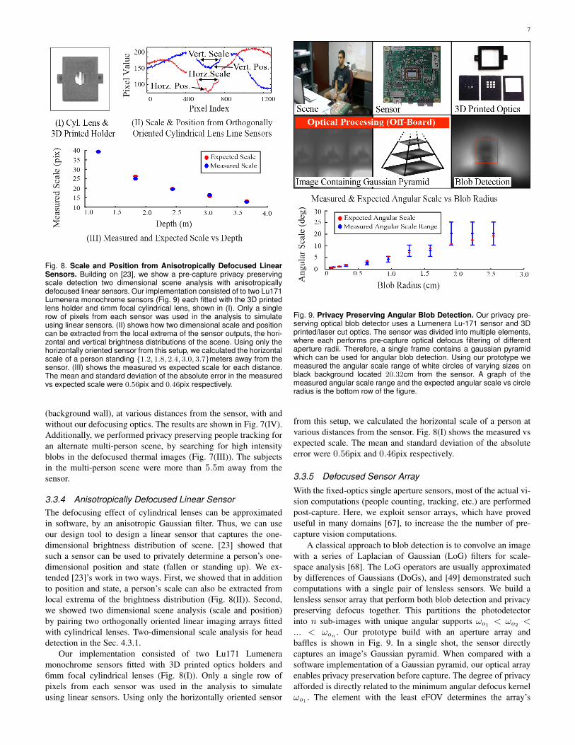
Fig. 9. Privacy Preserving Angular Blob Detection. Our privacy pre-serving optical blob detector uses a Lumenera Lu-171 sensor and 3Dprinted/laser cut optics. The sensor was divided into multiple elements,where each performs pre-capture optical defocus filtering of differentaperture radii. Therefore, a single frame contains a gaussian pyramidwhich can be used for angular blob detection. Using our prototype wemeasured the angular scale range of white circles of varying sizes onblack background located 20.32cm from the sensor. A graph of themeasured angular scale range and the expected angular scale vs circleradius is the bottom row of the figure.
from this setup, we calculated the horizontal scale of a person atvarious distances from the sensor. Fig. 8(I) shows the measured vsexpected scale. The mean and standard deviation of the absoluteerror were 0.56pix and 0.46pix respectively.
3.3.5 Defocused Sensor Array
With the fixed-optics single aperture sensors, most of the actual vi-sion computations (people counting, tracking, etc.) are performedpost-capture. Here, we exploit sensor arrays, which have proveduseful in many domains [67], to increase the the number of pre-capture vision computations.
A classical approach to blob detection is to convolve an imagewith a series of Laplacian of Gaussian (LoG) filters for scale-space analysis [68]. The LoG operators are usually approximatedby differences of Gaussians (DoGs), and [49] demonstrated suchcomputations with a single pair of lensless sensors. We build alensless sensor array that perform both blob detection and privacypreserving defocus together. This partitions the photodetectorinto n sub-images with unique angular supports !
o1 < !o2 <
... < !o
n
. Our prototype build with an aperture array andbaffles is shown in Fig. 9. In a single shot, the sensor directlycaptures an image’s Gaussian pyramid. When compared with asoftware implementation of a Gaussian pyramid, our optical arrayenables privacy preservation before capture. The degree of privacyafforded is directly related to the minimum angular defocus kernel!o1 . The element with the least eFOV determines the array’s

8
eFOV (although this is relaxed in the next section). Finally, theprivacy preserving advantage of these arrays comes with tradeoffs;for example, the optical array provides a fixed sampling of thescale space (scale granularity) and can estimate blobs only in afixed scale range.
We built a privacy preserving angular scale-space blob de-tector. In Fig. 9 we show our prototype, which consisted of acamera (Lu-171, Lumenera Inc.) with custom 3D-printed templateassembly and binary templates cut into black card paper using a100-micron laser (VLS3.50, Versa Inc.). We divided the cameraphotodetector plane into nine single-aperture sensor elements us-ing opaque baffles created from layered paper to prevent crosstalkbetween the sensor elements. The Lu-171 has a resolution of1280x1024 so the photodetector array was partitioned into a 3x3array of 320x320 pixels.
We validated our theory experimentally by using a prototypeto determine the angular scale range of white circles of varyingsizes on black background located 20.32cm from the sensor. Theresults are shown in Fig. 9. The angular scale range was correctlydetected for all of the circles except for the circle with radius0.64, which was off by 0.52 degrees. The angular supports for theprototype used in the experiment were {!
o1 = 0.44�,!o2 =
0.82�,!o3 = 0.97�,!
o4 = 1.26�,!o5 = 1.89�,!
o6 =3.06�,!
o7 = 5.48�,!o8 = 10.35�,!
o9 = 20.21�}.As an example application, we developed a second prototype
for low-power head tracking. Head-tracking was achieved byfirst detecting regions of interest using scale-space blob detectionand then running Viola-Jones object on the detected regions ofinterest. Identifying regions of interest using scale-space analysisdecreased the image search area for the Viola-Jones detector by50%. Fig. 9. shows a frame from a 2 minute office sequence, wherethe head was tracked correctly in 98% of frames. The opticalparameters of the prototype used to capture the office sequencewere {� = 4�,!
o1 = 9.76�,!o2 = 20.28�,!
o3 = 40.37�},which correspond to a minimum distance z
min
= 46.9cm, fordegrading features of 8cm and an eFOV of 39.54�. The Viola-Jones object detector was trained and tested on images of headblobs moving in an various office scenes.
3.4 LimitationsAlthough, in this paper, we show various example vision tasks thatwork well with optically defocused data, there are many visiontasks for which this is not the case. Furthermore, although de-blurring of heavily defocused images is an open problem [69],[70], [71], [72], [73], [74], [75], the use optical defocus for privacymay still be susceptible to reverse engineering.
4 PROGRAMMABLE PRIVACY OPTICS
In this section, we provide a framework, which leverages pro-grammable privacy optics to enable pre-capture implementationsof mask-based privacy algorithms such as k-anonymity and black-out.
4.1 Privacy OpticsThe proposed framework, illustrated in Fig. 10(I), consists of anoutput sensor (approximated by an ideal pinhole camera), whoseviewing path is split between the scene and an active optical mask,such as a projector or electronic display, and a pre-capture privacypreserving alignment sensor. With this setup, masking of sensitive
Fig. 10. Programmable Optics for Pre-Capture Privacy. In (I), weshow a ray diagram for our programmable optics-based pre-captureprivacy framework. In (II), we show the required mappings between thevarious system components. In (III), we demonstrate how to reduce thevolume occupied by the display and beamsplitter, determined by lbeamand lmask. For the perspective case, we show that there exists twoconfigurations with identical, minimum volume.
targets requires five steps: 1) Capture alignment image usingalignment sensor; 2) Segment targets in the alignment image; 3)Generate privacy masks using target segmentations; 4) Displayprivacy masks on electronic display; 5) Capture private imageusing output sensor. We formulate these five steps as follows.
The radiance I measured at each camera pixel (x, y) thatviews a scene point P is given by,
I(x, y) = eP
IP
+ eM
Idisplay
(M(x, y)), (6)
where IP
is the radiance from P , M is the privacy mask displayedby the electronic display, I
display
maps a privacy mask pixelintensity to its displayed radiance, and e
P
and eM
are the ratiosof the optical path split between the scene and the mask, whichcan range from 0 to 1. M(x, y) is given by
M(x, y) =X
1it�1
Fi
(H1(x, y)) (7)
where H1 is a transformation between the camera and maskplanes, and F
i
are the masks for the t segmented target planesin the alignment image. The masks F
i
are given by
Fi
(x, y) =
8<
:0, L(x0, y0) = 0
P1jk�1
wj
Dj
(H2(H3(x, y))), L(x0, y0) = 1
(8)

9
Fig. 11. Pre-Capture Black-out, K-Anonymity, and Face Recognition. We designed two programmable optics-based pre-capture privacy sensors.Our first prototype, Physical Setup 1, consisted of a 5” LED, a 2” beam splitter, and a Microsoft kinect fitted with our privacy sleeve (Fig. 5). Thecolor camera on the kinect was used as the system camera and the defocused TOF was used as the segmentation sensor. We implemented apre-caputure black-out using this prototype by masking the target with high intensity masks such that the pixels corresponding to the target wereoverexposed in the resulting camera images. Segmentation was acheived using the native Microsoft Kinect segmentation algorithm. Our secondprototype, Physical Setup 2, consisted of an 27” LED, a 14” beam splitter, a webcam, and the pair orthogonally oriented defocused linear sensorsfrom Fig. 8. The webcam was used as the system camera and the line sensors were used as the alignment sensors. Using this prototype weimplemented pre-capture k-anonymity for faces and privacy preserving face recognition.
where (x0, y0) = H1(H2(x, y)), Dj
are digital images, wj
are user defined weights, Li
(x, y) is binary segmentation in thealignment image for target i, H2 is a transformation between thesegmented target plane and the camera, and H3 is a transformationbetween each digital images and the segmented target plane. If thealignment sensor and the camera are collocated and of the sameresolution, H2 is an identity matrix. If they are not collocated, thenH2 varies for each segmented target plane and is depth dependent.Similarly, if the camera and the display mask are collocated andof the same resolution, H1 is an identity matrix. A graphicalillustration of these transformations is given in Fig. 10(II).
4.2 Miniaturization
We reduce the volume of the optics for small form factor plat-forms. For many algorithms it is desirable that the resolutionof the display be equal to or greater than the resolution of thesensor. Here we discuss how to reduce the size of the optical setupwhile still maintaining the desired display resolution. We assumethat the camera sensor in Fig. 10 is optimally miniaturized by amethod such as [49]. For clarity we consider a 2D ray diagram,but since our optics are symmetric these arguments hold in threedimensions. Let the beamsplitter angle be fixed at � and the sensorFOV be ✓. Let the minimum size of the mask that still affords thedesired resolution be M
min
. W.l.o.g let the mask be perpendicularto the reflected optical axis.
This leaves just two degrees of freedom for the optics; thesensor-beamsplitter distance l
beam
along the sensor’s optical axisand the mask-beamsplitter distance l
mask
along the reflectedoptical axis. In an orthographic version of optics, shown in Fig.10 (I), the size of the mask does not change as it is translatedtowards the sensor. Therefore, a mask of minimum size M
min
can be moved as close as possible to the sensor without occludingthe field-of-view as in Fig. 10 (I).
In the perspective case [76] the size of the mask reduces asit slides along the pencil of rays, as in Fig. 10 (II). Once the
minimum mask size Mmin
is reached, that configuration has theminimum optical size, given by 4CDE’s area.
We show that there exists an alternate choice, in the perspectivecase, for the minimum optical size. To maintain the minimumresolution, any mask position closer to the sensor must be verti-cally shifted, as in Fig. 10 (II). The area of these optics is givenby 4C
0D
0E + C
0B
0BC . From similar triangles, we can write
4C0D
0E as being created from 4CDE by a scale factor 1
s
, andthen equate the two configurations in Fig. 10 (II),
4CDE(1� 1
s) = C
0B
0BC. (9)
Consider 4CDE = 4COE + 4ODE. From the angle-side-angle theorem, this becomes,
4CDE =
l2beam sin
✓2 sin�
2 sin(
✓2 � �)
+
l2beam sin
✓2 sin�
2 sin(
✓2 + �)
. (10)
Since 4AB0C
0is a scaled version of 4ABC , the quadrilateral
area C0B
0BC =
4ABC(1� 1
s2) =
Mminlmask
2
(1� 1
s2). (11)
Putting Eq. 10 and Eq. 11 into Eq. 9, and setting constant C1 =sin ✓
2 sin�
2 sin( ✓
2��)+
sin ✓
2 sin�
2 sin( ✓
2+�),
s =
Mminlmask
2C1l2beam �Mminlmask, (12)
which is an equation for the scaling factor s such that the twodesigns in Fig. 10 (II) have the same area. Therefore we havefound two designs that provide the required resolution within thesmallest optical dimensions.

10
4.3 Example Sensor Designs
4.3.1 Alignment with Defocused Line SensorsIn this section we show two example applications, k-anonymityfor faces and privacy preserving face recognition. Our prototype,labeled Physical Setup 2 in Fig. 11, consisted of an 27” LED forthe display, a 14” beam splitter, a webcam, and a pair orthogonallyoriented linear sensors sensors with 6mm focal length cylindricallenses. The webcam was used as the output camera and the pairof line sensors were used as the alignment sensors. Output imageswere captured at 30 FPS.
K-anonymity for faces [8], [9] enables face de-identification byaveraging together a target face image with k� 1 of its neighbors(according to some similarity metric). The resulting average imagehas an algorithm-invariant face recognition rate upper bound of 1
k
.We present what is, to our knowledge, the first ever optical imple-mentation of k-anonymity for faces. Target faces were averagedwith k � 1 faces from a database by displaying privacy masks,generated via linear combinations of k�1 software aligned faces.We assumed the k � 1 faces, D
j
in Eq. 8, were captured undersimilar illumination environments to the target face. In our currentimplementation, access to the database could allow an adversaryto compromise anonymity. In future implementations we plan torandomize the value k, the choice of k neighbors and the blendingweights w
i
to make de-anonymity combinatorially hard.Recent efforts have resulted in privacy preserving face recog-
nition frameworks [77], [78], [79], [80]. Here we show a similarexample application, using optical k-anonymity for faces, thatallows recognition of membership to a class while preservingprivacy. Each target is first anonymized via optical k-anonymitywith k-1 faces corresponding to individuals that are not in themembership class and are not known to the party performing facerecognition. The anonymized face is compared to each face in themembership class using a similarity metric. If the similarity scoreis greater than a threshold then the anonymized face is matchedwith that individual. With no match, the system returns the k-anonymized face. We simulated this system using two subsets ofthe FERET Database [81], each containing a single image of a setof people. For k = {2, 4, 6, 8, 10}, 100 individuals from one subsetwere randomly selected as targets and anonymized with their k�1nearest neighbors found in the same subset by simulating the effectof the cylindrical lens by integrating the image vertically andmatching with the cosine similarity. The similarity between thisk-anonymized image and 11 other images from the second imagesubset was then computed using Face++’s verification algorithms[82]. One of these is the target image from the second imagesubset, while the remaining were randomly selected. Simulationresults are shown in 11. Such a system was built. Fig. 11 showsexamples where individuals were correctly discriminated.
4.3.2 Alignment with Defocused Time-of-Flight SensorBlack-out is a well known mask-based privacy algorithm forpreserving the anonymity of individuals in video data. We im-plemented pre-caputure black-out using the prototype, labeledPhysical Setup 1 in Fig. 11, which consisted of a 5” LED displaymask, a 2” beam splitter, and a Microsoft kinect. The Kinect wasfitted with 3D printed privacy optics to defocus the time-of-flightcamera (Fig. 5). The color camera on the kinect was used as theoutput camera and the defocused TOF was used as the alignmentsensor. Black-out was achieved by masking the target with highintensity masks such that the pixels corresponding to the targets
were overexposed in the resulting output camera image. The nativeMicrosoft Kinect segmentation software was used to segment thetargets. Fig. 11(I) shows our results for black-out faces and bodies.Output images were captured at 15 FPS.
4.4 LimitationsMiniaturization is limited by use of a display because it com-mits the system to continuous power use. The primary privacylimitation is that the framework relies on post-capture patternrecognition and alignment. Thus, privacy may be compromised,if pattern recognition or alignment fails at any frame.
5 SUMMARY
Most privacy preserving systems for computer vision, processimages after capture. There exists a moment of vulnerabilityin such systems, after capture, when privacy has not yet beenenforced. Our privacy preserving sensors filter the incident light-field before image capture, while light passes through the sensoroptics, so sensitive information is never measured by the sensor.Within this framework, we introduce a programmable privacyoptics that enable pre-capture implementations of mask-basedprivacy algorithms, such as black-out and k-anonymity, and fixedprivacy optics that provide both privacy and utility for time-of-flight, thermal, and near-infrared sensors. We also show theoryfor miniaturizing the proposed designs, including a novel ”opticalknapsack” solution for finding a field-of-view-optimal arrange-ment of optical elements. Our privacy preserving sensors enableapplications such as accurate depth sensing, full-body motiontracking, multiple people tracking and low-power blob detection.
REFERENCES
[1] D. Bitouk, N. Kumar, S. Dhillon, P. Belhumeur, and S. K. Nayar,“Face swapping: automatically replacing faces in photographs,” in ACMTransactions on Graphics (TOG), vol. 27, no. 3. ACM, 2008, p. 39.
[2] M. Boyle, C. Edwards, and S. Greenberg, “The effects of filtered videoon awareness and privacy,” in Proceedings of the 2000 ACM conferenceon Computer supported cooperative work. ACM, 2000, pp. 1–10.
[3] C. Neustaedter, S. Greenberg, and M. Boyle, “Blur filtration fails topreserve privacy for home-based video conferencing,” ACM Transactionson Computer-Human Interaction (TOCHI), vol. 13, no. 1, pp. 1–36, 2006.
[4] G. Loukides and J. Shao, “Data utility and privacy protection trade-off ink-anonymisation,” in Proceedings of the 2008 international workshop onPrivacy and anonymity in information society. ACM, 2008, pp. 36–45.
[5] C. Thorpe, F. Li, Z. Li, Z. Yu, D. Saunders, and J. Yu, “A coprime blurscheme for data security in video surveillance,” Pattern Analysis andMachine Intelligence, IEEE Transactions on, vol. 35, no. 12, pp. 3066–3072, 2013.
[6] F. Dufaux and T. Ebrahimi, “Scrambling for privacy protection in videosurveillance systems,” Circuits and Systems for Video Technology, IEEETransactions on, vol. 18, no. 8, pp. 1168–1174, 2008.
[7] F. Li, Z. Li, D. Saunders, and J. Yu, “A theory of coprime blurred pairs,”in Computer Vision (ICCV), 2011 IEEE International Conference on.IEEE, 2011, pp. 217–224.
[8] L. Sweeney, “k-anonymity: A model for protecting privacy,” Interna-tional Journal of Uncertainty, Fuzziness and Knowledge-Based Systems,vol. 10, no. 05, pp. 557–570, 2002.
[9] E. M. Newton, L. Sweeney, and B. Malin, “Preserving privacy byde-identifying face images,” Knowledge and Data Engineering, IEEETransactions on, vol. 17, no. 2, pp. 232–243, 2005.
[10] R. Gross, L. Sweeney, F. De la Torre, and S. Baker, “Semi-supervisedlearning of multi-factor models for face de-identification,” in ComputerVision and Pattern Recognition, 2008. CVPR 2008. IEEE Conference on.IEEE, 2008, pp. 1–8.
[11] R. Gross, E. Airoldi, B. Malin, and L. Sweeney, “Integrating utility intoface de-identification,” in Privacy Enhancing Technologies. Springer,2006, pp. 227–242.
11
[12] B. Driessen and M. Durmuth, “Achieving anonymity against major facerecognition algorithms,” in Communications and Multimedia Security.Springer, 2013, pp. 18–33.
[13] P. Agrawal and P. Narayanan, “Person de-identification in videos,” Cir-cuits and Systems for Video Technology, IEEE Transactions on, vol. 21,no. 3, pp. 299–310, 2011.
[14] J. Fernandez-Berni, R. Carmona-Galan, R. del Rıo, R. Kleihorst,W. Philips, and A. Rodrıguez-Vazquez, “Focal-plane sensing-processing:A power-efficient approach for the implementation of privacy-awarenetworked visual sensors,” Sensors, vol. 14, no. 8, pp. 15 203–15 226,2014.
[15] M. Mrityunjay and P. Narayanan, “The de-identification camera,” inComputer Vision, Pattern Recognition, Image Processing and Graphics(NCVPRIPG), 2011 Third National Conference on. IEEE, 2011, pp.192–195.
[16] A. Chattopadhyay and T. E. Boult, “Privacycam: a privacy preservingcamera using uclinux on the blackfin dsp,” in Computer Vision andPattern Recognition, 2007. CVPR’07. IEEE Conference on. IEEE, 2007,pp. 1–8.
[17] T. Winkler and B. Rinner, “Trustcam: Security and privacy-protection foran embedded smart camera based on trusted computing,” in AdvancedVideo and Signal Based Surveillance (AVSS), 2010 Seventh IEEE Inter-national Conference on. IEEE, 2010, pp. 593–600.
[18] G. R. Nelson, G. A. Jullien, and O. Yadid-Pecht, “Cmos image sensorwith watermarking capabilities,” in Circuits and Systems, 2005. ISCAS2005. IEEE International Symposium on. IEEE, 2005, pp. 5326–5329.
[19] T. Winkler, A. Erdelyi, and B. Rinner, “Trusteye. m4: Protecting thesensornot the camera,” in Advanced Video and Signal Based Surveillance(AVSS), 2014 11th IEEE International Conference on. IEEE, 2014, pp.159–164.
[20] J. Fernandez-Berni, R. Carmona-Galan, and A. Rodriguez-Vazquez,“Single-exposure hdr technique based on tunable balance between localand global adaptation.”
[21] F. Pittaluga, A. Zivkovic, and S. J. Koppal, “Sensor-level privacy for ther-mal cameras,” in 2016 IEEE International Conference on ComputationalPhotography (ICCP). IEEE, 2016, pp. 1–12.
[22] S. Browarek, “High resolution, low cost, privacy preserving humanmotion tracking system via passive thermal sensing,” Ph.D. dissertation,Massachusetts Institute of Technology, 2010.
[23] S. Nakashima, Y. Kitazono, L. Zhang, and S. Serikawa, “Developmentof privacy-preserving sensor for person detection,” Procedia-Social andBehavioral Sciences, vol. 2, no. 1, pp. 213–217, 2010.
[24] M. O’Toole, R. Raskar, and K. N. Kutulakos, “Primal-dual coding toprobe light transport.” ACM Trans. Graph., vol. 31, no. 4, p. 39, 2012.
[25] J. Dai, J. Wu, B. Saghafi, J. Konrad, and P. Ishwar, “Towards privacy-preserving activity recognition using extremely low temporal and spatialresolution cameras,” in The Sixth IEEE Workshop on Analysis andModeling of Faces and Gestures, CVPR 2015.
[26] Y. Zhang, Y. Lu, H. Nagahara, and R.-I. Taniguchi, “Anonymous cam-era for privacy protection,” in Pattern Recognition (ICPR), 2014 22ndInternational Conference on, Aug 2014, pp. 4170–4175.
[27] M. Wakin, J. Laska, M. Duarte, D. Baron, S. Sarbotham, D. Takhar,K. Kelly, and R. Baranuik, “An architecture for compressive imaging,”ICIP, 2006.
[28] M. F. Duarte, M. A. Davenport, D. Takhar, J. N. Laska, T. Sun,K. E. Kelly, and R. G. Baraniuk, “Single-pixel imaging via compressivesampling,” IEEE Signal Processing Magazine, vol. 25, no. 2, p. 83, 2008.
[29] M. A. Davenport, M. F. Duarte, M. B. Wakin, J. N. Laska, D. Takhar,K. F. Kelly, and R. G. Baraniuk, “The smashed filter for compressiveclassification and target recognition,” in Electronic Imaging 2007. Inter-national Society for Optics and Photonics, 2007, pp. 64 980H–64 980H.
[30] S. Zhou, J. Lafferty, and L. Wasserman, “Compressed and privacy-sensitive sparse regression,” Information Theory, IEEE Transactions on,vol. 55, no. 2, pp. 846–866, 2009.
[31] A. M. Abdulghani and E. Rodriguez-Villegas, “Compressive sensing:from compressing while sampling to compressing and securing whilesampling,” in Engineering in Medicine and Biology Society (EMBC),2010 Annual International Conference of the IEEE. IEEE, 2010, pp.1127–1130.
[32] M. J. Wainwright, M. I. Jordan, and J. C. Duchi, “Privacy awarelearning,” in Advances in Neural Information Processing Systems, 2012,pp. 1430–1438.
[33] M. Cossalter, M. Tagliasacchi, and G. Valenzise, “Privacy-enabled objecttracking in video sequences using compressive sensing,” in AdvancedVideo and Signal Based Surveillance, 2009. AVSS’09. Sixth IEEE Inter-national Conference on. IEEE, 2009, pp. 436–441.
[34] W. Wolf, B. Ozer, and T. Lv, “Smart cameras as embedded systems,”Computer, vol. 35, no. 9, pp. 48–53, 2002.
[35] V. Brajovic and T. Kanade, “Computational sensor for visual trackingwith attention,” Solid-State Circuits, IEEE Journal of, vol. 33, no. 8, pp.1199–1207, 1998.
[36] Y. LeCun, L. Bottou, Y. Bengio, and P. Haffner, “Gradient-based learningapplied to document recognition,” Proceedings of the IEEE, vol. 86,no. 11, pp. 2278–2324, 1998.
[37] B. Gyselinckx, C. Van Hoof, J. Ryckaert, R. Yazicioglu, P. Fiorini,and V. Leonov, “Human++: autonomous wireless sensors for body areanetworks,” in Custom Integrated Circuits Conference, Proceedings of theIEEE 2005. IEEE, 2005, pp. 13–19.
[38] A. Chandrakasan, N. Verma, J. Kwong, D. Daly, N. Ickes, D. Finchel-stein, and B. Calhoun, “Micropower wireless sensors,” Power, vol. 30,no. 35, p. 40, 2006.
[39] B. H. Calhoun, D. C. Daly, N. Verma, D. F. Finchelstein, D. D. Wentzloff,A. Wang, S. Cho, and A. P. Chandrakasan, “Design considerationsfor ultra-low energy wireless microsensor nodes,” Computers, IEEETransactions on, vol. 54, no. 6, pp. 727–740, 2005.
[40] A. P. Sample, D. J. Yeager, P. S. Powledge, A. V. Mamishev, andJ. R. Smith, “Design of an rfid-based battery-free programmable sensingplatform,” Instrumentation and Measurement, IEEE Transactions on,vol. 57, no. 11, pp. 2608–2615, 2008.
[41] E. Steltz and R. S. Fearing, “Dynamometer power output measurementsof miniature piezoelectric actuators,” Mechatronics, IEEE/ASME Trans-actions on, vol. 14, no. 1, pp. 1–10, 2009.
[42] A. Wilhelm, B. Surgenor, and J. Pharoah, “Evaluation of a micro fuelcell as applied to a mobile robot,” in Mechatronics and Automation, 2005IEEE International Conference, vol. 1. IEEE, 2005, pp. 32–36.
[43] J. W. Goodman et al., Introduction to Fourier optics. McGraw-hill NewYork, 1968, vol. 2.
[44] F. T. Yu and S. Jutamulia, “Optical pattern recognition,” Optical PatternRecognition, by Francis TS Yu, Suganda Jutamulia, Cambridge, UK:Cambridge University Press, 2008, vol. 1, 2008.
[45] R. Raskar, A. Agrawal, and J. Tumblin, “Coded exposure photography:motion deblurring using fluttered shutter,” ACM Transactions on Graph-ics (TOG), vol. 25, no. 3, pp. 795–804, 2006.
[46] R. Ng, “Fourier slice photography,” in ACM Transactions on Graphics(TOG), vol. 24, no. 3. ACM, 2005, pp. 735–744.
[47] A. Levin, R. Fergus, F. Durand, and W. T. Freeman, “Image and depthfrom a conventional camera with a coded aperture,” in ACM Transactionson Graphics (TOG), vol. 26, no. 3. ACM, 2007, p. 70.
[48] R. Fergus, A. Torralba, and W. T. Freeman, “Random lens imaging,”2006.
[49] S. J. Koppal, I. Gkioulekas, T. Young, H. Park, K. B. Crozier, G. L.Barrows, and T. Zickler, “Toward wide-angle microvision sensors,” IEEETransactions on Pattern Analysis & Machine Intelligence, no. 12, pp.2982–2996, 2013.
[50] S. J. Koppal, I. Gkioulekas, T. Zickler, and G. L. Barrows, “Wide-anglemicro sensors for vision on a tight budget,” in Computer Vision andPattern Recognition (CVPR), 2011 IEEE Conference on. IEEE, 2011,pp. 361–368.
[51] A. Zomet and S. K. Nayar, “Lensless imaging with a controllableaperture,” in Computer Vision and Pattern Recognition, 2006 IEEEComputer Society Conference on, vol. 1. IEEE, 2006, pp. 339–346.
[52] S. K. Nayar, V. Branzoi, and T. E. Boult, “Programmable imaging:Towards a flexible camera,” International Journal of Computer Vision,vol. 70, no. 1, pp. 7–22, 2006.
[53] U. M. Erdem and S. Sclaroff, “Automated camera layout to satisfy task-specific and floor plan-specific coverage requirements,” Computer Visionand Image Understanding, vol. 103, no. 3, pp. 156–169, 2006.
[54] A. O. Ercan, D. B. Yang, A. El Gamal, and L. J. Guibas, “Optimalplacement and selection of camera network nodes for target localization,”in Distributed computing in sensor systems. Springer, 2006, pp. 389–404.
[55] S. Soro and W. B. Heinzelman, “On the coverage problem in video-basedwireless sensor networks,” in Broadband Networks, 2005. BroadNets2005. 2nd International Conference on. IEEE, 2005, pp. 932–939.
[56] A. O. Ercan, D. B. Yang, A. E. Gamal, and L. J. Guibas, “On coverageissues in directional sensor networks: A survey,” Ad Hoc Networks, vol. 9,no. 7, pp. 1238–1255, 2011.
[57] K. Miyamoto, “Fish eye lens,” JOSA, vol. 54, no. 8, pp. 1060–1061,1964.
[58] R. Swaminathan, M. D. Grossberg, and S. K. Nayar, “Caustics of cata-dioptric cameras,” in Computer Vision, 2001. ICCV 2001. Proceedings.Eighth IEEE International Conference on, vol. 2. IEEE, 2001, pp. 2–9.

12
[59] P. J. Phillips, H. Moon, S. A. Rizvi, and P. J. Rauss, “The feret evaluationmethodology for face-recognition algorithms,” 2000.
[60] F. Dufaux and T. Ebrahimi, “A framework for the validation of privacyprotection solutions in video surveillance,” in Multimedia and Expo(ICME), 2010 IEEE International Conference on. IEEE, 2010, pp.66–71.
[61] D. S. Bolme, J. R. Beveridge, M. Teixeira, and B. A. Draper, “The csuface identification evaluation system: Its purpose, features and structure,”2003.
[62] E. Newton, L. Sweeney, and B. Malin, “Preserving privacy by de-identifying facial images,” CMU Technical Report CMU-CS-03-119,2003.
[63] H. Dyckhoff, “A typology of cutting and packing problems,” EuropeanJournal of Operational Research, vol. 44, no. 2, pp. 145–159, 1990.
[64] S. Martello and P. Toth, Knapsack problems: algorithms and computerimplementations. John Wiley & Sons, Inc., 1990.
[65] R. E. Korf, M. D. Moffitt, and M. E. Pollack, “Optimal rectanglepacking,” Annals of Operations Research, vol. 179, no. 1, pp. 261–295,2010.
[66] F. Pittaluga and S. J. Koppal, “Privacy preserving optics for miniaturevision sensors,” in Proceedings of the IEEE Conference on ComputerVision and Pattern Recognition, 2015, pp. 314–324.
[67] L. Streeter and A. A. Dorrington, “Simple harmonic error cancellation intime of flight range imaging,” Optics letters, vol. 40, no. 22, pp. 5391–5394, 2015.
[68] T. Lindeberg, Scale-space theory in computer vision. Springer Science& Business Media, 1993.
[69] J. Pan, Z. Hu, Z. Su, and M.-H. Yang, “Deblurring face images withexemplars,” in Computer Vision–ECCV 2014. Springer, 2014, pp. 47–62.
[70] H. Zhang, J. Yang, Y. Zhang, N. M. Nasrabadi, and T. S. Huang,“Close the loop: Joint blind image restoration and recognition withsparse representation prior,” in Computer Vision (ICCV), 2011 IEEEInternational Conference on. IEEE, 2011, pp. 770–777.
[71] M. Nishiyama, H. Takeshima, J. Shotton, T. Kozakaya, and O. Yam-aguchi, “Facial deblur inference to improve recognition of blurred faces,”in Computer Vision and Pattern Recognition, 2009. CVPR 2009. IEEEConference on. IEEE, 2009, pp. 1115–1122.
[72] M. Nishiyama, A. Hadid, H. Takeshima, J. Shotton, T. Kozakaya, andO. Yamaguchi, “Facial deblur inference using subspace analysis forrecognition of blurred faces,” Pattern Analysis and Machine Intelligence,IEEE Transactions on, vol. 33, no. 4, pp. 838–845, 2011.
[73] S. Farsiu, M. D. Robinson, M. Elad, and P. Milanfar, “Fast and robustmultiframe super resolution,” Image processing, IEEE Transactions on,vol. 13, no. 10, pp. 1327–1344, 2004.
[74] B. Bascle, A. Blake, and A. Zisserman, “Motion deblurring and super-resolution from an image sequence,” in Computer Vision ECCV’96.Springer, 1996, pp. 571–582.
[75] W. Dong, D. Zhang, G. Shi, and X. Wu, “Image deblurring and super-resolution by adaptive sparse domain selection and adaptive regulariza-tion,” Image Processing, IEEE Transactions on, vol. 20, no. 7, pp. 1838–1857, 2011.
[76] J. Gluckman and S. K. Nayar, “Catadioptric stereo using planar mirrors,”International Journal of Computer Vision, vol. 44, no. 1, pp. 65–79, 2001.
[77] A.-R. Sadeghi, T. Schneider, and I. Wehrenberg, “Efficient privacy-preserving face recognition,” in Information, Security and Cryptology–ICISC 2009. Springer, 2010, pp. 229–244.
[78] Z. Erkin, M. Franz, J. Guajardo, S. Katzenbeisser, I. Lagendijk, andT. Toft, “Privacy-preserving face recognition,” in Privacy EnhancingTechnologies. Springer, 2009, pp. 235–253.
[79] M. Osadchy, B. Pinkas, A. Jarrous, and B. Moskovich, “Scifi-a systemfor secure face identification,” in Security and Privacy (SP), 2010 IEEESymposium on. IEEE, 2010, pp. 239–254.
[80] T. A. Kevenaar, G. J. Schrijen, M. van der Veen, A. H. Akkermans,and F. Zuo, “Face recognition with renewable and privacy preservingbinary templates,” in Automatic Identification Advanced Technologies,2005. Fourth IEEE Workshop on. IEEE, 2005, pp. 21–26.
[81] P. J. Phillips, H. Moon, S. A. Rizvi, and P. J. Rauss, “The feret evaluationmethodology for face-recognition algorithms,” Pattern Analysis andMachine Intelligence, IEEE Transactions on, vol. 22, no. 10, pp. 1090–1104, 2000.
[82] H. Fan, Z. Cao, Y. Jiang, Q. Yin, and C. Doudou, “Learning deep facerepresentation,” arXiv preprint arXiv:1403.2802, 2014.
Francesco Pittaluga Francesco Pittauga is cur-rently a graduate student at the University ofFlorida’s ECE department. Prior to joining UF,Francesco attended Tufts University where hereceived a B.S. in Electrical Engineering with asecond major in Computer Science. His interestsspan computer vision, machine learning, andcomputational photography.
Sanjeev J. Koppal Sanjeev J. Koppal is an as-sistant professor at the University of Florida’sECE department. Prior to joining UF, he wasa researcher at the Texas Instruments Imag-ing R&D lab. Sanjeev obtained his Masters andPh.D. degrees from the Robotics Institute atCarnegie Mellon University, where his adviserwas Prof. Srinivasa Narasimhan. After CMU, hewas a post-doctoral research associate in theSchool of Engineering and Applied Sciences atHarvard University, with Prof. Todd Zickler. He
received his B.S. degree from the University of Southern California in2003. His interests span computer vision, computational photographyand optics and include novel cameras and sensors, 3D reconstruction,physics-based vision and active illumination.