Embed Size (px)
Citation preview
1
Process Analytic Division
Revolutionary Revolutionary Innovations inInnovations in
Continuous Emissions Monitoring Systems (CEMS)Continuous Emissions Monitoring Systems (CEMS)
November 10, 2004
2
IntroductionIntroductionIntroductionIntroduction• Continuous Emissions Monitoring Systems
(CEMS) are vital in power plant and process industries.
• These systems traditionally cause facilities to endure high installation and maintenance costs.
• However, revolutionary innovations now present significant cost-saving opportunities to CEMS users.
3
Traditional CEMS RequirementsTraditional CEMS RequirementsTraditional CEMS RequirementsTraditional CEMS Requirements• A sampling probe mounted at the appropriate height on a
stack
• A heated sample line to transport moisture-laden gas samples to the analysis station
• A shelter building erected and maintained to provide the proper operating environment for the analysis equipment
• A programmable logic controller (PLC) to manage the monitoring process
• A suitable data acquisition system (DAS) to generate data, reports and records
• Installation costs up to $150,000 or more per stack
4
New Innovative CEMSNew Innovative CEMSNew Innovative CEMSNew Innovative CEMS• Recent CEMS advancements allow emission
monitoring accuracy and data handling at a significantly lower cost than with systems created from discrete components through innovations like:
• Direct stack/duct enclosure mounting
• Split systems
• Smaller enclosures
• Reduced enclosure power requirements
• Plug and Play Ethernet Web-browser interfaces
5
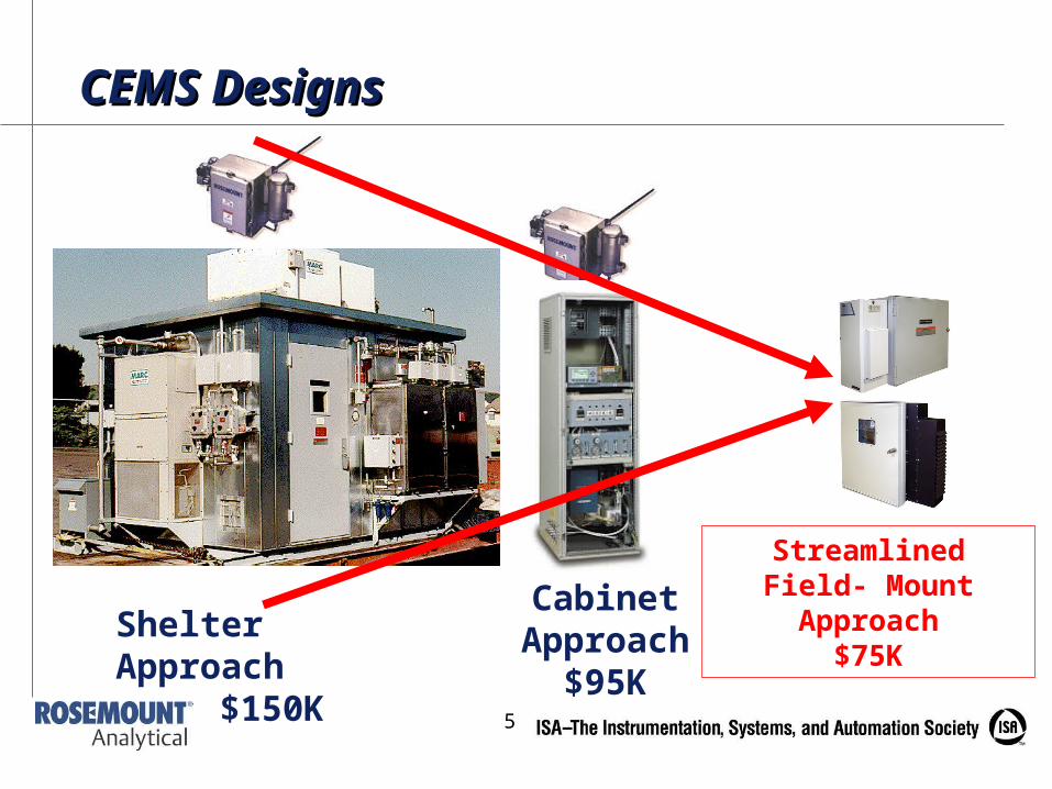
CEMS DesignsCEMS Designs
Shelter Approach$150K
Cabinet Approach
$95K
Streamlined Field- Mount Approach
$75K
6
Direct Enclosure MountingDirect Enclosure MountingDirect Enclosure MountingDirect Enclosure Mounting• The elimination of a heated sample line between a sample probe and
a sample conditioning/analysis system can create significant cost savings and save considerable headaches and process downtime or violations because:
• The installed cost of heated sample lines is about $100 per foot (the average 150-foot line costs about $15,000).
• Sample lines are delicate, require skilled installers and are often damaged during installation.
• Sample lines require diligent maintenance on the sample probe.
• Process upsets or process equipment failures can sometimes lead to plugging of the sample line, necessitating its replacement.
• Heated sample lines are long lead-time items, often taking weeks to procure even in emergency situations.
7
Direct Enclosure Mounting (con’t.)Direct Enclosure Mounting (con’t.)Direct Enclosure Mounting (con’t.)Direct Enclosure Mounting (con’t.)• Real-time measurements are important for timely feedback on critical
emission levels.
• With long sample lines the analysis process is delayed, causing potentially harmful delays in emission level corrections.
• However, close-coupled or direct mounting of sample handling and analysis enclosures eliminates the need for a sample line and provides the following advantages:
• Reduced transport time for sample reading, providing a near-real-time measurement signal
• Faster, continuous measurement for efficient pollution reduction system control, quicker adjustments, and reduced emission limits violations
• Elimination of heated sample lines, providing energy savings as they typically use 25-50% of energy consumed by the CEMS
8
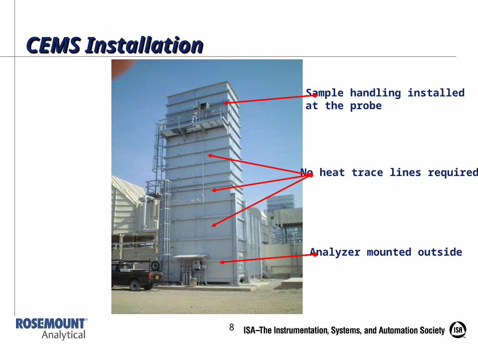
Sample handling installedat the probe
No heat trace lines required
Analyzer mounted outside
CEMS InstallationCEMS InstallationCEMS InstallationCEMS Installation
9
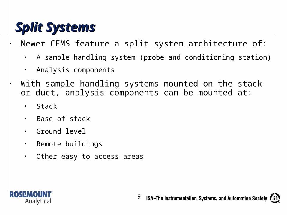
Split SystemsSplit SystemsSplit SystemsSplit Systems• Newer CEMS feature a split system architecture of:
• A sample handling system (probe and conditioning station)
• Analysis components
• With sample handling systems mounted on the stack or duct, analysis components can be mounted at:
• Stack
• Base of stack
• Ground level
• Remote buildings
• Other easy to access areas
10
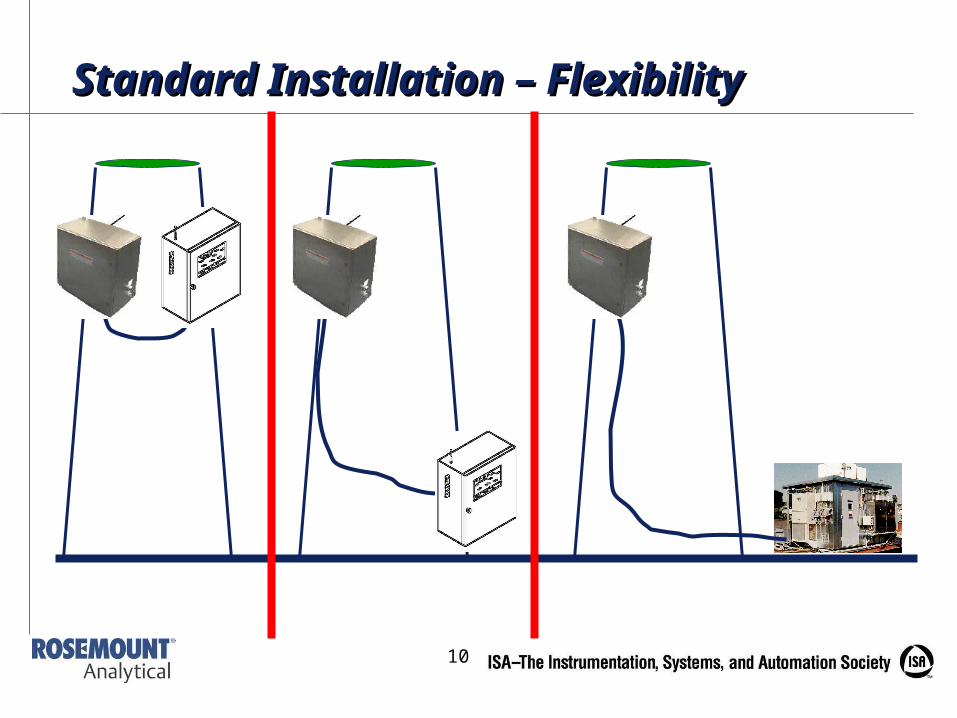
Standard Installation – FlexibilityStandard Installation – Flexibility
11
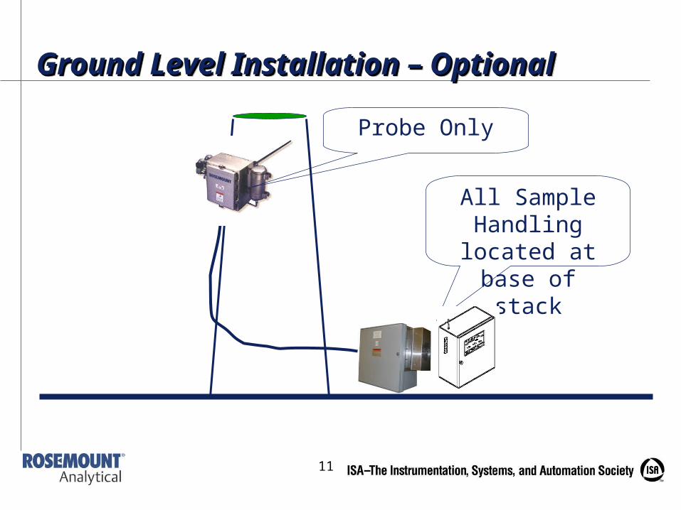
All Sample Handling located at base of stack
Probe Only
Ground Level Installation – OptionalGround Level Installation – OptionalGround Level Installation – OptionalGround Level Installation – Optional
12
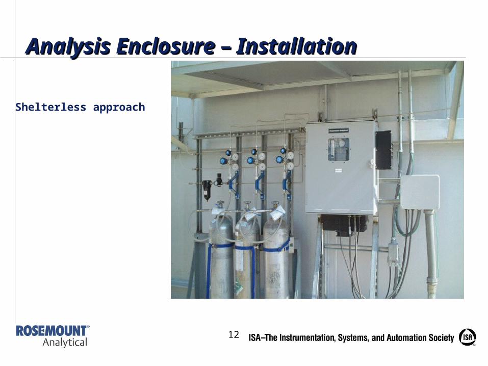
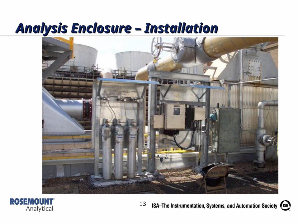
Shelterless approach
Analysis Enclosure – InstallationAnalysis Enclosure – InstallationAnalysis Enclosure – InstallationAnalysis Enclosure – Installation
13
Analysis Enclosure – InstallationAnalysis Enclosure – InstallationAnalysis Enclosure – InstallationAnalysis Enclosure – Installation
14
Smaller EnclosuresSmaller EnclosuresSmaller EnclosuresSmaller Enclosures• Smaller, self-contained CEMS enclosures provide a
compact, field-mountable combustion exhaust gas measurement system and offer:
• Installation in limited space locations
• Ratings for unprotected outdoor exposure, eliminating the need for concrete pad foundations and expensive shelters
• Compact, efficient cooling/heating control systems to maintain constant temperatures
• Reduce/eliminate building maintenance expenses
• Significant energy savings
• Easier, less expensive installation (cranes and other heavy lifting equipment no longer required)
15
New Installation OptionsNew Installation OptionsNew Installation OptionsNew Installation Options• Smaller system size makes Stainless Steel
enclosures more affordable
• Great for EMI/RFI environments
• Meets spec requirements for petrochemical facilities
• Skip the box and HVAC
• 2’x2’ Plate-mount for use in limited space situations on interior walls of existing shelters
• Sample handling enclosure can be mounted on outside of existing shelters.
16
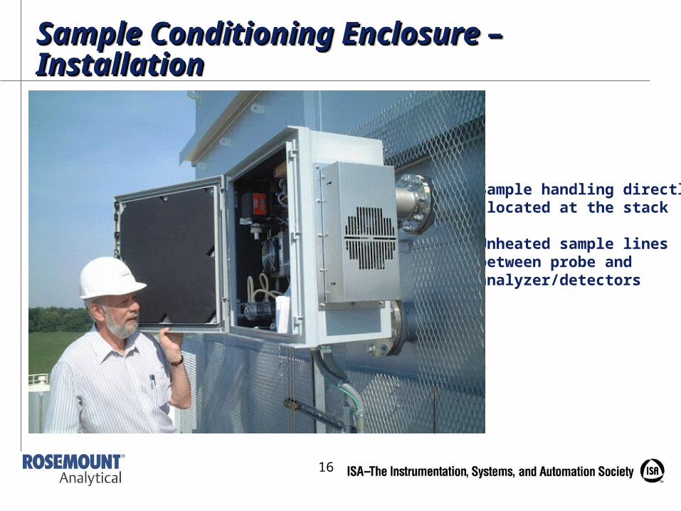
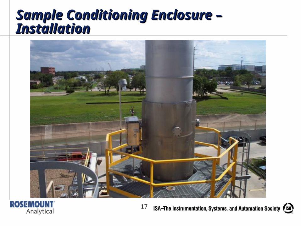
•Sample handling directly located at the stack
•Unheated sample lines between probe and analyzer/detectors
Sample Conditioning Enclosure – Sample Conditioning Enclosure – InstallationInstallationSample Conditioning Enclosure – Sample Conditioning Enclosure – InstallationInstallation
17
Sample Conditioning Enclosure – Sample Conditioning Enclosure – InstallationInstallationSample Conditioning Enclosure – Sample Conditioning Enclosure – InstallationInstallation
18
Reduced Enclosure Power Reduced Enclosure Power RequirementsRequirementsReduced Enclosure Power Reduced Enclosure Power RequirementsRequirements
• CEMS users now recognize lower power requirements through:
• Significant reduction of heating and cooling costs through elimination of shelter.
• Lower power magnitudes than traditional systems (500 Watts versus 30,000 Volt-Amps)
• Elimination of heated sample line power draw (18 Watts/foot)
19
Use Proven TechnologiesUse Proven TechnologiesUse Proven TechnologiesUse Proven Technologies• New packaging of existing technology
• Benefits of using proven technology:
• Avoid situations where too many changes at one time limits the diagnosis of root problem
• New packaging is already available using currently preferred methods for both sample handling and analysis.
• Hassles and expenses related to variances or local EPA acceptance of unfamiliar methods are eliminated
20
Proven Sample Handling TechnologiesProven Sample Handling TechnologiesProven Sample Handling TechnologiesProven Sample Handling Technologies• Using proven sample handling techniques also eliminates
costly troubleshooting and maintenance on new technologies, especially since some new packaging options use the same proven techniques as conventionally packaged systems.
• Unproven techniques may result in higher costs and significant lost uptime due to:
• Learning curves
• Unavailability of trained and experienced service resources
• Limitation on spare parts
• Higher costs for exotic premium technologies
• Slow service response
21
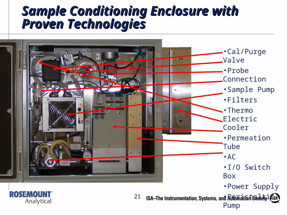
Sample Conditioning Enclosure with Sample Conditioning Enclosure with Proven TechnologiesProven Technologies
•Cal/Purge Valve
•Probe Connection
•Sample Pump
•Filters
•Thermo Electric Cooler
•Permeation Tube
•AC
•I/O Switch Box
•Power Supply
•Peristaltic Pump
22
Proven Sensor TechnologiesProven Sensor TechnologiesProven Sensor TechnologiesProven Sensor Technologies• Eliminate costly diagnostics and maintenance on new
technologies
• New packaging options use the same proven techniques as conventionally packaged systems
• Use proven EPA Reference Methods
• Proven detectors now available:
• Chemiluminescent NOx
• Nondispersive Infrared (NDIR) CO
• Nondispersive Ultraviolet (NDUV) SO2
• Paramagnetic O2
• Electrochemical O2
23
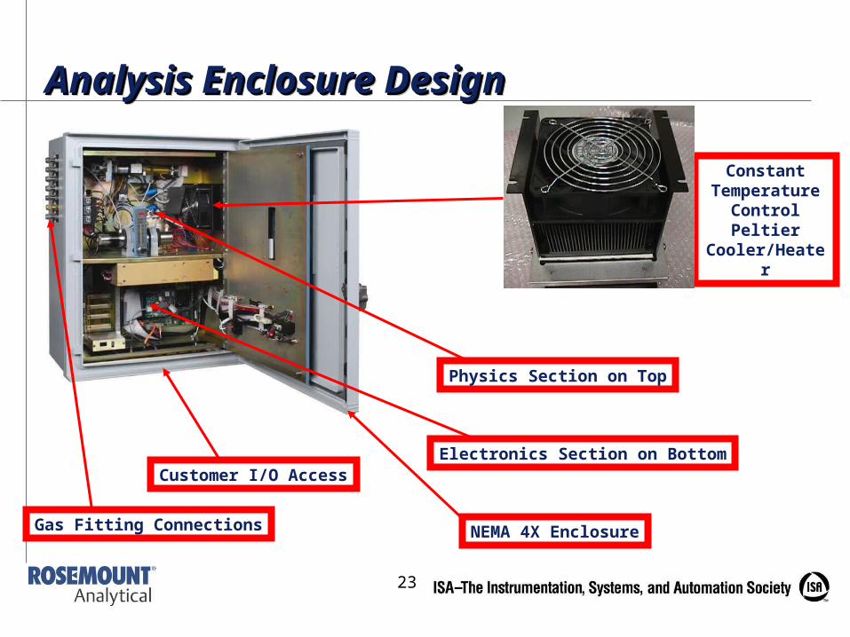
Electronics Section on Bottom
Physics Section on Top
Customer I/O Access
Gas Fitting Connections
Constant Temperature
Control Peltier Cooler/Heater
NEMA 4X Enclosure
Analysis Enclosure DesignAnalysis Enclosure DesignAnalysis Enclosure DesignAnalysis Enclosure Design
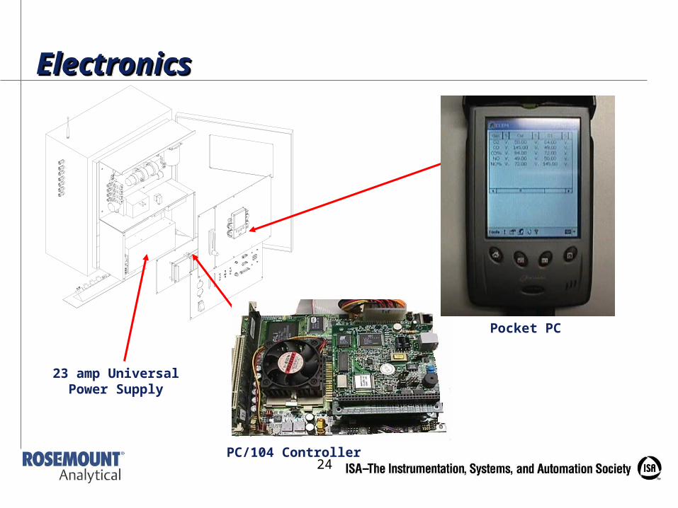
24PC/104 Controller
Pocket PC
23 amp Universal Power Supply
ElectronicsElectronicsElectronicsElectronics
25
Embedded PCEmbedded PCEmbedded PCEmbedded PC• Choose a system utilizing an industrial computer
standard such as PC-104, as this controller features:
• Resistance to plant environmental factors such as radio frequency interference (RFI), heat and vibration
• Commercially available parts
• Smaller form factors
• Acceptance as an industrial standard
26
Embedded PC (cont’d)Embedded PC (cont’d)Embedded PC (cont’d)Embedded PC (cont’d)• Built-in personal computers (PCs) with DAS
available on CEMS models that provide:
• Automatic function controls
• System limit and failure alarms
• Data averaging for regulatory requirements (40 CFR 60)
• Pollution calculations for diluent corrections, mass emissions
• Status flags for all values, calculations, averages.
• Calibration Logs, Alarm Logs, Emissions Logs
• Calibration correction factors for each analyzer output
27
Embedded PC (cont’d)Embedded PC (cont’d)Embedded PC (cont’d)Embedded PC (cont’d)• Months of data can be stored in the embedded PCs and
can be:
• 256 MB flash drive (no moving parts) can hold 3 months data
• Downloaded via a handheld PC
• Accessed remotely through an Ethernet network
• Network drive access through Windows Explorer
• Windows drive mapping
• Downloaded in Microsoft Excel or Microsoft Word format for further analysis and storage
• Interfaced to DCS, Data Acquisition Systems, etc. through OPC Servers
28
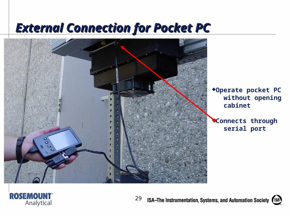
Handheld PC Operator InterfaceHandheld PC Operator InterfaceHandheld PC Operator InterfaceHandheld PC Operator Interface• Advanced CEMS feature handheld PCs at the
analysis enclosure that offer:
• Same access as remote web-browser displays
• Drop-down menus that eliminate the need to scroll through multiple levels for values or commands
• Operability outside the enclosure via a cable for more comfortable and easier data reading
• Leave it in the enclosure or take it with you
• Password protection, software for CEMS operations only – ensures the handheld stays with the CEMS
29
Operate pocket PC without opening cabinet
Connects through serial port
External Connection for Pocket PCExternal Connection for Pocket PCExternal Connection for Pocket PCExternal Connection for Pocket PC
30
Plug and Play Ethernet Web-browser InterfacePlug and Play Ethernet Web-browser InterfacePlug and Play Ethernet Web-browser InterfacePlug and Play Ethernet Web-browser Interface• Eliminating the need for custom software drivers to interface
with plant control systems, CEMS now feature:
• HTML Web-browser access to operating parameters, system setup and process data (Internet Explorer)
• No setup required – type IP address once and bookmark!
• Access from any plant computer, home PC, or even from out-of-town corporate offices.
• TCP-IP communications protocol for intranet and Internet communications
• Simple message structure for easy programming, parsing by OPC Servers, etc.
• Simple file format allows direct import into spreadsheets and database without any modifications or programming
31
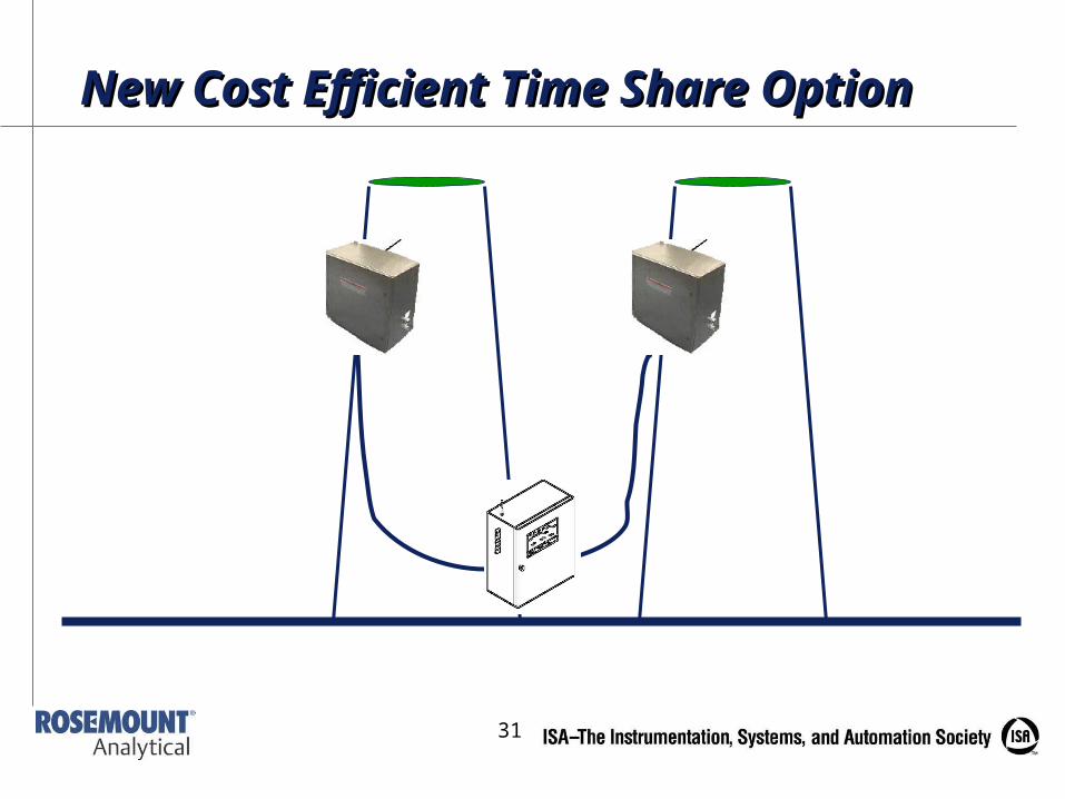
New Cost Efficient Time Share OptionNew Cost Efficient Time Share Option
32
Time Share FeaturesTime Share FeaturesTime Share FeaturesTime Share Features• Software configuration of switching time, stack
names, individual calibration parameters for each stack, etc.
• Automatic status flags for all values, averages, calculations, etc. for stack that is in by-pass (I.e. not being sampled)
• Analog output hold for stack in bypass, digital contact out to indicate which stack is being sampled.
33
Time Share Option BenefitsTime Share Option BenefitsTime Share Option BenefitsTime Share Option Benefits• Eliminates the cost of a second set of analyzers
• Great for two stacks for multiple emissions source installations such as gas turbine plants, auxiliary boilers, etc.
• Great for before/after SCR control signals
• Great for determining NH3 Slip using before/after SCR NOx measurement and mass balance formula.
• Perfect for automatic switch-over applications for backup boilers, bypass stacks, etc.
34
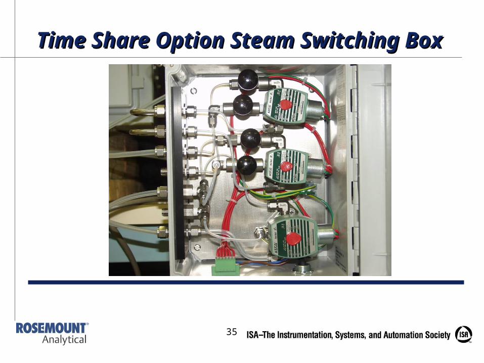
Steam Switching BoxSteam Switching BoxSteam Switching BoxSteam Switching Box• Continuous time-share switching of conditioned
sample streams
• Needle valves for flow balancing multiple sample streams
• Needle valves for flow balancing calibration gases to multiple sample probes
35
Time Share Option Steam Switching Time Share Option Steam Switching BoxBox
36
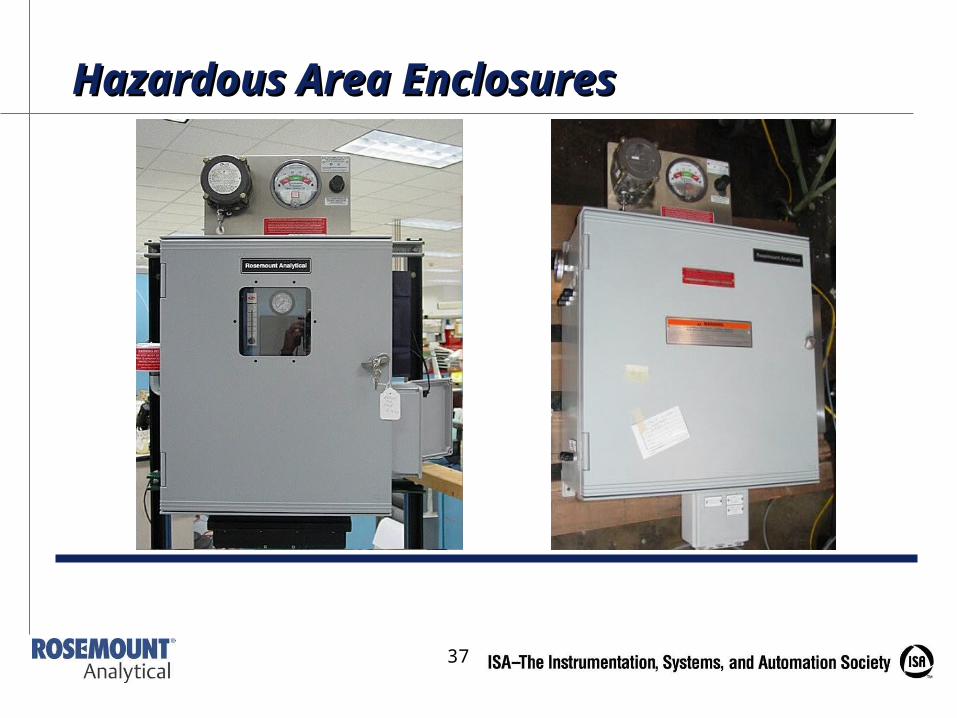
Hazardous Area OptionsHazardous Area OptionsHazardous Area OptionsHazardous Area Options• Sample Handling and/or Analyzer Enclosure can be upgraded for
Class 1 Div 2 areas:
• Z-purge enclosure
• Class 1 Div 2 HVAC units
• Class 1 Div 2 external power supply and cooling fan
• Hazardous area rated junction box
• Good solution for petrochemical applications where hazardous area rated shelters are too big/expensive
• Sample handling enclosure at probe eliminates sample line and associated hazardous area requirements
• Many stack locations are above the maximum height of the hazardous area – allowing the use of general purpose sample handling enclosures
37
Hazardous Area EnclosuresHazardous Area Enclosures
38
Future EnhancementsFuture EnhancementsFuture EnhancementsFuture Enhancements• Additional enhancements are expected in CEMS
development to simplify installation and operating costs even more, including:
• NDIR CO2 Bench
• Direct replacement for dilution systems with new low NOx limits
• Supports new CO2 monitoring and reporting requirements
• Wireless remote access
• Redundant hardware for mission-critical applications