Embed Size (px)
Citation preview

VHDL 4
BUILDING BLOCKS OF
A COMPUTER
1
http://www.cse.cuhk.edu.hk/~mcyang/teaching.html

We will learn
• Combinational circuit and sequential circuit
• Building blocks of a computer
• Control units are state machines, which consist of flip-
flops, decoders, multiplexers, etc.
• Beware that, there are usually more than one way to
design the same digital system in VHDL
2

Combinational vs. Sequential Circuits
There are two types of circuit designs:
• Combinational Circuit: it has no memory
• Its outputs are a function of the present value of the inputs only.
• As soon as inputs are changed, the information about the previous inputs is
lost, that is, combinational logic circuits have no memory.
• Example: inverter, tri state buffer, encoder/decoder, multiplexer, bi-
directional bus, etc.
• Sequential Circuit: it has memory
• It changes state and output based on some conditions, such as
input or clock signal.
• Its outputs are also dependent upon past inputs.
• In other words the output of a sequential circuit may depend upon its previous
outputs and so in effect has some form of memory.
• Example: latch, flip-flops (FFs), etc.
3
http://www.ee.surrey.ac.uk/Projects/CAL/seq-switching/General_seq_circ.htm
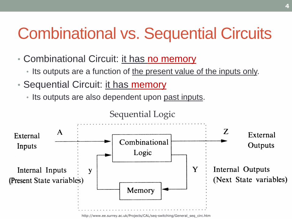
Combinational vs. Sequential Circuits
4
• Combinational Circuit: it has no memory
• Its outputs are a function of the present value of the inputs only.
• Sequential Circuit: it has memory
• Its outputs are also dependent upon past inputs.
Sequential Logic
http://www.ee.surrey.ac.uk/Projects/CAL/seq-switching/General_seq_circ.htm
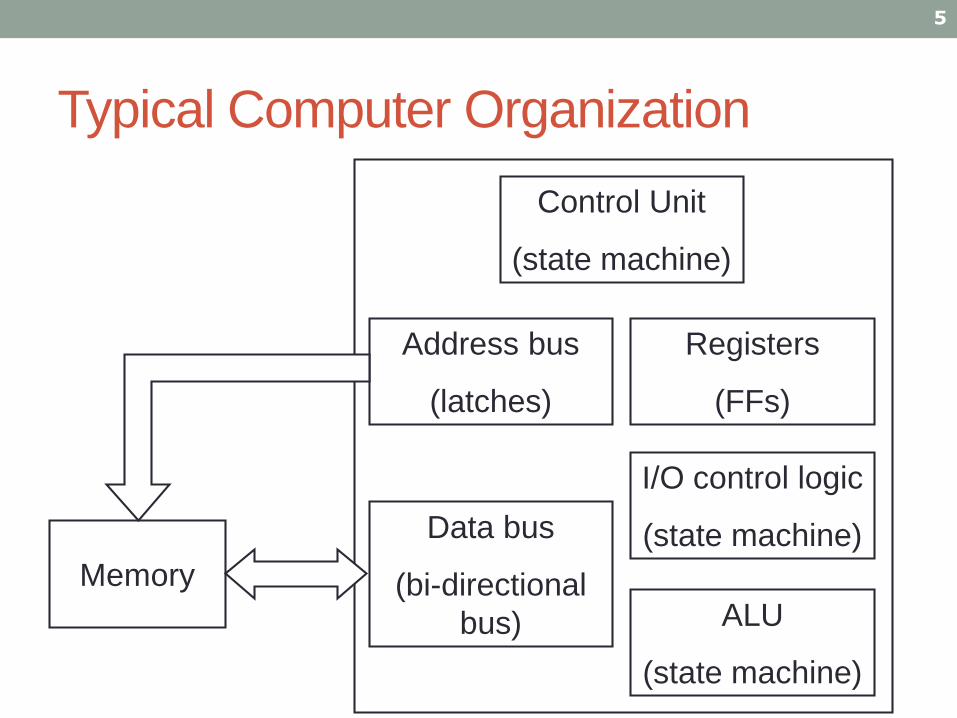
Typical Computer Organization
5
ALU
(state machine)
Control Unit
(state machine)
I/O control logic
(state machine)
Registers
(FFs)
Data bus
(bi-directional
bus)
Memory
Address bus
(latches)

Use VHDL to Make Building Blocks
1) Latch
2) Flip-flop with asynchronous reset
• Reset the circuit no matter with the clock
3) Flip-flop with synchronous reset
• Reset the circuit only at the clock edge
4) Tri state buffer
5) Decoder
6) Multiplexer
7) Bi-directional bus
6
Sequential
Circuit
Combinational
Circuit
D Q
C
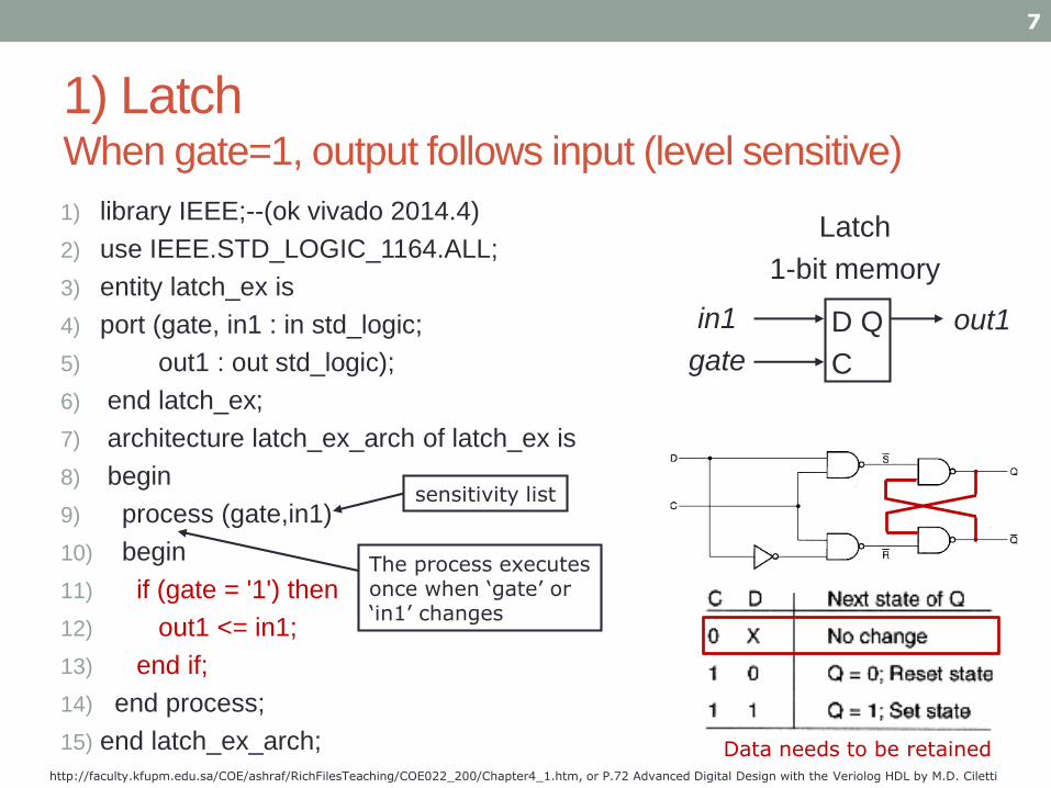
1) LatchWhen gate=1, output follows input (level sensitive)
7
http://faculty.kfupm.edu.sa/COE/ashraf/RichFilesTeaching/COE022_200/Chapter4_1.htm, or P.72 Advanced Digital Design with the Veriolog HDL by M.D. Ciletti
in1
gate
out1
Latch
1-bit memory
1) library IEEE;--(ok vivado 2014.4)
2) use IEEE.STD_LOGIC_1164.ALL;
3) entity latch_ex is
4) port (gate, in1 : in std_logic;
5) out1 : out std_logic);
6) end latch_ex;
7) architecture latch_ex_arch of latch_ex is
8) begin
9) process (gate,in1)
10) begin
11) if (gate = '1') then
12) out1 <= in1;
13) end if;
14) end process;
15) end latch_ex_arch;
The process executes once when ‘gate’ or ‘in1’ changes
sensitivity list
Data needs to be retained
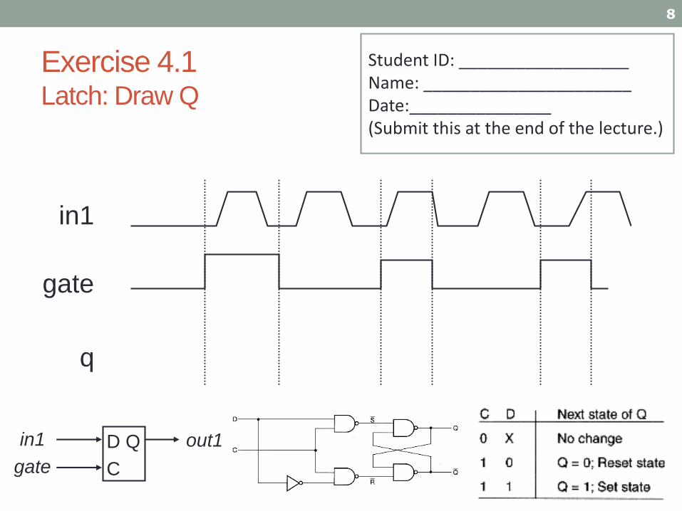
Exercise 4.1 Latch: Draw Q
8
in1
gate
q
Student ID: __________________Name: ______________________Date:_______________ (Submit this at the end of the lecture.)
D Q
C
in1
gate
out1
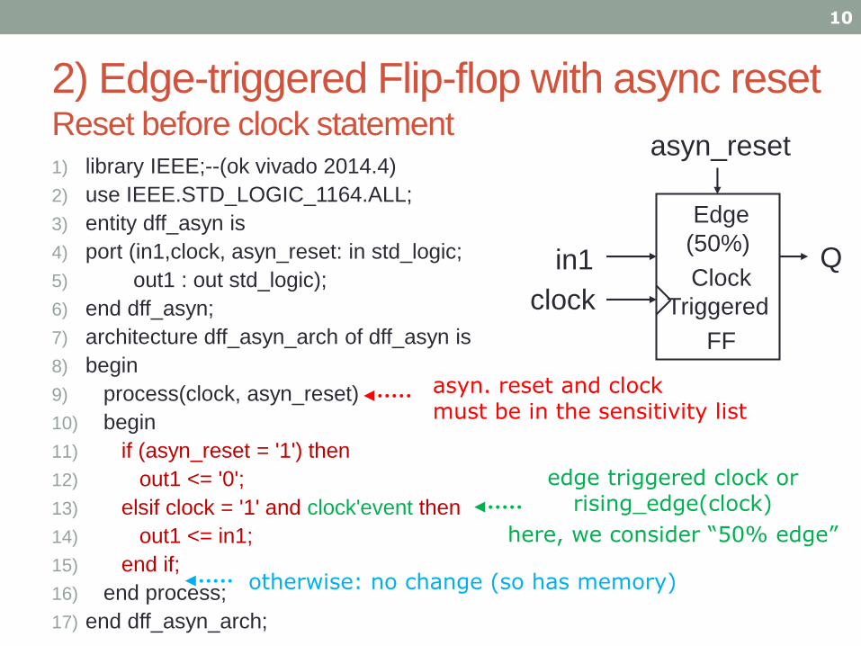
2) Edge-triggered Flip-flop with async resetReset before clock statement 1) library IEEE;--(ok vivado 2014.4)
2) use IEEE.STD_LOGIC_1164.ALL;
3) entity dff_asyn is
4) port (in1,clock, asyn_reset: in std_logic;
5) out1 : out std_logic);
6) end dff_asyn;
7) architecture dff_asyn_arch of dff_asyn is
8) begin
9) process(clock, asyn_reset)
10) begin
11) if (asyn_reset = '1') then
12) out1 <= '0';
13) elsif clock = '1' and clock'event then
14) out1 <= in1;
15) end if;
16) end process;
17) end dff_asyn_arch;
10
Qin1
clock
Edge
(50%)
Clock
Triggered
FF
asyn_reset
edge triggered clock orrising_edge(clock)
here, we consider “50% edge”
asyn. reset and clock must be in the sensitivity list
otherwise: no change (so has memory)

Exercise 4.2Edge-triggered Flip-flop with async reset
a) Draw Q
b) Explain the meaning of “50 %
clock trigger” for a Flip Flop.
Answer: ______________________
_____________________________
11
clock
in1
out1
asyn_reset is 0
Qin1
clock
Edge
(50%)
Clock
Triggered
FF
asyn_reset

Exercise 4.3
13
1) library IEEE;--(ok vivado 2014.4)
2) use IEEE.STD_LOGIC_1164.ALL;
3) entity dff_asyn is
4) port (in1,clock, asyn_reset: in std_logic;
5) out1 : out std_logic);
6) end dff_asyn;
7) architecture dff_asyn_arch of dff_asyn is
8) begin
9) process(clock, asyn_reset)
10) begin
11) if (asyn_reset = '1') then
12) out1 <= '0';
13) elsif clock = '1' and clock'event then
14) out1 <= in1;
15) end if;
16) end process;
17)end dff_asyn_arch;
a) When will line 9 be
executed?
Answer:
b) Which is more
“powerful”: clock or reset?
Answer:

3) Edge-triggered Flip-flop with sync resetClock before reset statement
15
1) library IEEE;--(ok vivado 2014.4)2) use IEEE.STD_LOGIC_1164.ALL;3) entity dff_syn is4) port (in1,clock, syn_reset: in std_logic;5) out1 : out std_logic);6) end dff_syn;7) architecture dff_syn_arch of dff_syn is8) --begin process(clock, syn_reset) -- 'syn_reset' can be removed9) begin process(clock) -- 'syn_reset' can be removed10) begin11) if clock = '1' and clock'event then12) if (syn_reset = '1') then13) out1 <= '0';14) else15) out1 <= in1;16) end if;17) end if;18) end process;19) end dff_syn_arch;
syn_reset
clock
out1
Din1
Discuss: Why syn_reset is not needed in the sensitivity list?
nested ifstatement
otherwise: no change

Difference between sync & async reset FF
16
• The order of the statements inside the process
determines synchronous or asynchronous reset
• if clock = '1' and clock'event then
• if (reset = '1') then – nested if statement
• if (reset = '1') then
• q <= '0';
• elsif clock = '1' and clock'event then
Sync. Reset Flip-Flop (check clock first)
Async. Reset Flip-Flop (check reset first)

Exercise 4.4
a) What is the difference between
• synchronous reset (syn-reset) flip-flops
• Answer:
• asynchronous reset (asyn-reset) flip-flops?
• Answer:
b) Discuss the difference between a latch and a flip flop.• In our course, by default all flip-flops are treated as 50% edge triggered flip-flops.
• Answer:
17

Use VHDL to Make Building Blocks
1) Latch
2) Flip-flop with asynchronous reset
• Reset the circuit no matter with the clock
3) Flip-flop with synchronous reset
• Reset the circuit only at the clock edge
4) Tri state buffer
5) Decoder
6) Multiplexer
7) Bi-directional bus
19
Sequential
Circuit
Combinational
Circuit

4) Tri state buffer: using when-else(Use capital letter big Z for float, Z is a reserved character)
20
1) library IEEE;--(ok vivado 2014.4)
2) use IEEE.STD_LOGIC_1164.ALL;
3) entity tri_ex is
4) port (in1, control : in std_logic;
5) out1 : out std_logic);
6) end tri_ex;
7) architecture tri_ex_arch of tri_ex is
8) begin
9) out1 <= in1 when control = '1' else 'Z';
10) end tri_ex_arch;
out1
control
in1
Z=float state
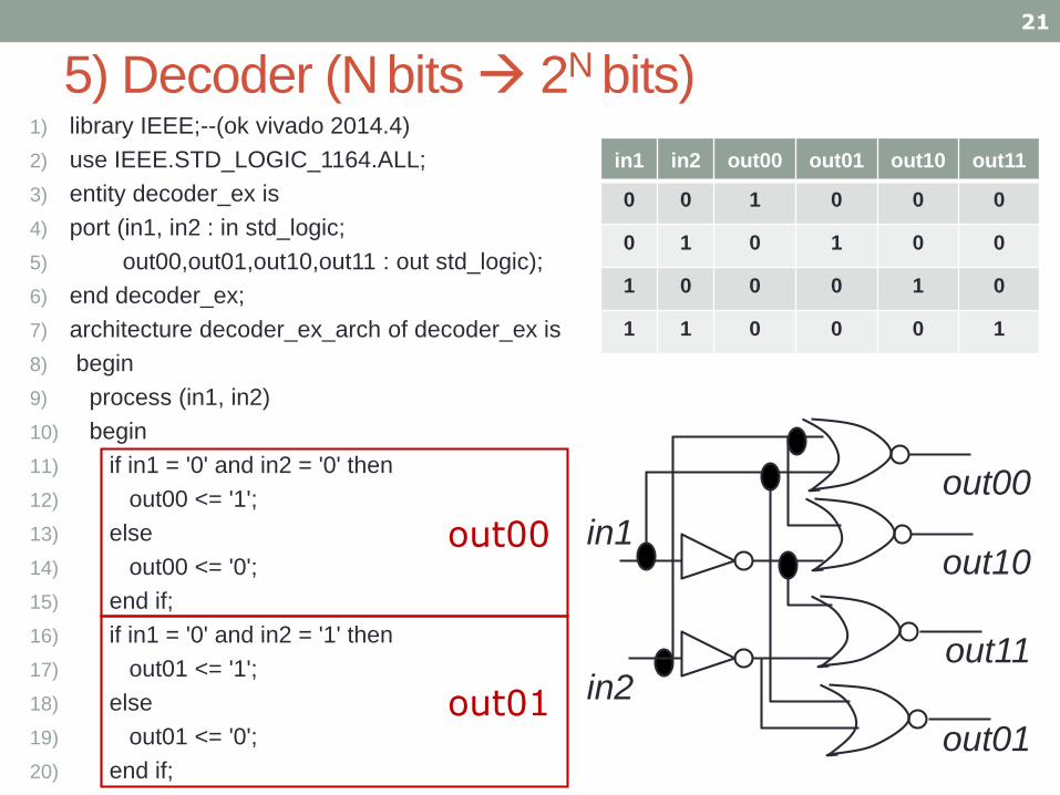
5) Decoder (Nbits 2N bits)
21
1) library IEEE;--(ok vivado 2014.4)
2) use IEEE.STD_LOGIC_1164.ALL;
3) entity decoder_ex is
4) port (in1, in2 : in std_logic;
5) out00,out01,out10,out11 : out std_logic);
6) end decoder_ex;
7) architecture decoder_ex_arch of decoder_ex is
8) begin
9) process (in1, in2)
10) begin
11) if in1 = '0' and in2 = '0' then
12) out00 <= '1';
13) else
14) out00 <= '0';
15) end if;
16) if in1 = '0' and in2 = '1' then
17) out01 <= '1';
18) else
19) out01 <= '0';
20) end if;
in1
in2
out00
out10
out11
out01out01
out00
in1 in2 out00 out01 out10 out11
0 0 1 0 0 0
0 1 0 1 0 0
1 0 0 0 1 0
1 1 0 0 0 1

22
21) if in1 = '1' and in2 = '0' then
22) out10 <= '1';
23) else
24) out10 <= '0';
25) end if;
26) if in1 = '1' and in2 = '1' then
27) out11 <= '1';
28) else
29) out11 <= '0';
30) end if;
31) end process;
32) end decoder_ex_arch;
5) Decoder (cont’d)
out10
out11
in1
in2
out00
out10
out11
out01
in1 in2 out00 out01 out10 out11
0 0 1 0 0 0
0 1 0 1 0 0
1 0 0 0 1 0
1 1 0 0 0 1

6) Multiplexer (2N bits N bits)
1) library IEEE;--(vivado 2014.4 tested ok)
2) use IEEE.STD_LOGIC_1164.ALL;
3) entity mux is
4) port (in1,in2, ctrl : in std_logic;
5) out1 : out std_logic);
6) end mux;
7) architecture mux_arch of mux is
8) begin
9) process (in1, in2, ctrl)
10) begin
11) if ctrl = '0' then
12) out1 <= in1;
13) else
14) out1 <= in2;
15) end if;
16) end process; end mux_arch;
23
Muxout1in1
in2
crtl
in1
in2out1
crtl

7) Bi-directional Bus
1) library IEEE;--(ok vivado 2014.4)
2) use IEEE.STD_LOGIC_1164.ALL;
3) entity inout_ex is
4) port (io1, io2 : inout std_logic;
5) ctrl : in std_logic);
6) end inout_ex;
7) architecture inout_ex_arch of inout_ex is
8) begin
9) io1 <= io2 when ctrl = '1' else 'Z';
10) -- “io1” follows “io2_in”
11) io2 <= io1 when ctrl = '0' else 'Z';
12) -- “io2” follows “io1_in”
13) end inout_ex_arch;
24
io1
ctrl = 1
io2
io1
ctrl = 0
io2
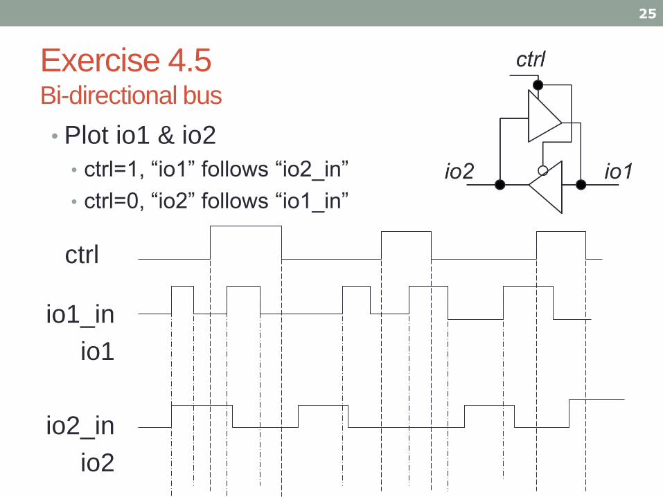
Exercise 4.5Bi-directional bus
25
• Plot io1 & io2
• ctrl=1, “io1” follows “io2_in”
• ctrl=0, “io2” follows “io1_in”
io1_in
io1
io2_in
io2
ctrl
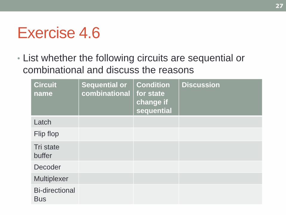
Exercise 4.6
27
• List whether the following circuits are sequential or
combinational and discuss the reasons
Circuit
name
Sequential or
combinational
Condition
for state
change if
sequential
Discussion
Latch
Flip flop
Tri state
buffer
Decoder
Multiplexer
Bi-directional
Bus

Quick revision
• You should know how to design
• Sequential logics
• asynchronous & synchronous reset flip-flops
• tri state buffers
• Combinational logics
• decoders
• multiplexers
• bi-directional bus
29
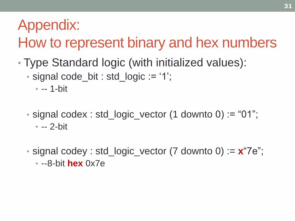
Appendix:
How to represent binary and hex numbers
• Type Standard logic (with initialized values):• signal code_bit : std_logic := ‘1’;
• -- 1-bit
• signal codex : std_logic_vector (1 downto 0) := “01”;
• -- 2-bit
• signal codey : std_logic_vector (7 downto 0) := x“7e”;
• --8-bit hex 0x7e
31


![[PPT]VHDL 3 Finite State Machines FSM - Chinese University …khwong/www2/ceng3430/vhdl5.pptx · Web viewVHDL 5FINITE STATE MACHINES (FSM) Some pictures are obtained from FPGA Express](https://img.pdfslide.net/doc/110x75/5b2b9a7b7f8b9a594c8b6a58/pptvhdl-3-finite-state-machines-fsm-chinese-university-khwongwww2ceng3430vhdl5pptx.jpg)