Embed Size (px)
DESCRIPTION
http://www.afa.com.eg/uploads/papers/2011/files/120112213738_3.1_2011_afa_uft_paper.pdf
Citation preview
Meeting environmental issues facing new and existing urea Fluid –bed Granulation with Plants
Mr. Harald Franzrahe
Process Manager - Uhde Fertilizer Technology B. V.
Netherlands
3.1 2011 - AFA - UFT Paper.doc Page 1
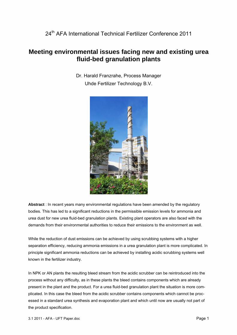
24th AFA International Technical Fertilizer Conference 2011
Meeting environmental issues facing new and existing urea fluid-bed granulation plants
Dr. Harald Franzrahe, Process Manager
Uhde Fertilizer Technology B.V.
Abstract : In recent years many environmental regulations have been amended by the regulatory
bodies. This has led to a significant reductions in the permissible emission levels for ammonia and
urea dust for new urea fluid-bed granulation plants. Existing plant operators are also faced with the
demands from their environmental authorities to reduce their emissions to the environment as well.
While the reduction of dust emissions can be achieved by using scrubbing systems with a higher
separation efficiency, reducing ammonia emissions in a urea granulation plant is more complicated. In
principle significant ammonia reductions can be achieved by installing acidic scrubbing systems well
known in the fertilizer industry.
In NPK or AN plants the resulting bleed stream from the acidic scrubber can be reintroduced into the
process without any difficulty, as in these plants the bleed contains components which are already
present in the plant and the product. For a urea fluid-bed granulation plant the situation is more com-
plicated. In this case the bleed from the acidic scrubber contains components which cannot be proc-
essed in a standard urea synthesis and evaporation plant and which until now are usually not part of
the product specification.
3.1 2011 - AFA - UFT Paper.doc Page 2
The bleed from the ammonia scrubber must be processed in some way. This processing can be done
in various ways.
In accordance with UFT's commitment to improve the fluid-bed granulation process UFT has
developed options for achieving ammonia emission reductions from fluid-bed urea granulation plants.
With UFT's Ammonia Convert Technology the acidic bleed from the ammonia scrubber has been suc-
cessful integrated into the granulation process.
In this paper various available and industrially proven options for granulation plant operators are pre-
sented. In especially UFT´s proprietary Ammonia Convert Technology, which combines minimized
ammonia emissions with reduced production cost will be discussed.
3.1 2011 - AFA - UFT Paper.doc Page 3
1 The UFT Fluid Bed Urea Granulation Technology Figure 1 shows the process flow diagram of the UFT Fluid Bed Urea Granulation process. Heart of the
plant is the granulator, where urea solution with a concentration of 97% is atomized into fine droplets
and sprayed onto the particles in the fluidized bed. Formaldehyde is added to the urea solution as
granulation additive and to improve storage properties.
Crushed oversize and fines coming from the screens are utilized in the granulator as seed material
and the particles continuously grow to their desired size by accretion. In the first cooler the product is
cooled down and via bucket elevator lifted to the screens, which separate coarse, fine and on-size
material. The on-size material is cooled down in the final cooler to the storage temperature and sent to
storage.
The major advantage of the UFT fluid bed urea granulation process is the melt concentration of 97%
urea. In this way the evaporating water is utilized in the granulator as additional coolant to remove the
heat of crystallization. This leads to the following features:
- Single stage evaporation unit in urea synthesis section
- Low biuret concentration in final product
- Low quantities of fluidization air needed in granulator
- Lower investment cost due to smaller granulator, less fluidization air, smaller scrubbing unit and single stage evaporation unit
- Low steam consumption in evaporation and granulation
- Low electrical energy consumption due to low amount of air required
Figure 2 shows a typical plant concept for a world class granulation plant. In this concept it can easily
be seen that the treatment of the off-gas from the granulation unit is a large section of the granulation
plant. The scrubbing systems for the air from the granulator and the fluid bed coolers therefore
contribute significantly to the investment and operating costs of the plant.
Their careful design and good operation are just as important as that of the granulation loop.

3.1 2011 - AFA - UFT Paper.doc Page 4
Figure 1 - Schematic of UFT granulation process
Figure 2 - World Scale Fluidized Bed Urea Granulation Plant
3.1 2011 - AFA - UFT Paper.doc Page 5
2 Emissions and emission limits from a fluidized bed granulation plant
There are three sources of emissions from a fluidized bed urea granulation plant
dust or particulate matter ammonia water vapor (opacity)
Since the last decades emission limits have been a key focus of the environmental protection agen-
cies. With the development of technology and increased public awareness the emission limits required
by the regulatory authorities or recommended by leading institutions have been continually reduced.
While the reduction of the permissible values primarily focuses on new plants and can be taken into
account during the design.
However, with plant lifetimes of over 30 years, some older plants are now also required to achieve
lower emission figures then was foreseen during their original design. Alternatively the new emission
limits are imposed when the plant is debottlenecked. This poses additional challenges as the limita-
tions of the existing facilities and the available space must be taken into account.
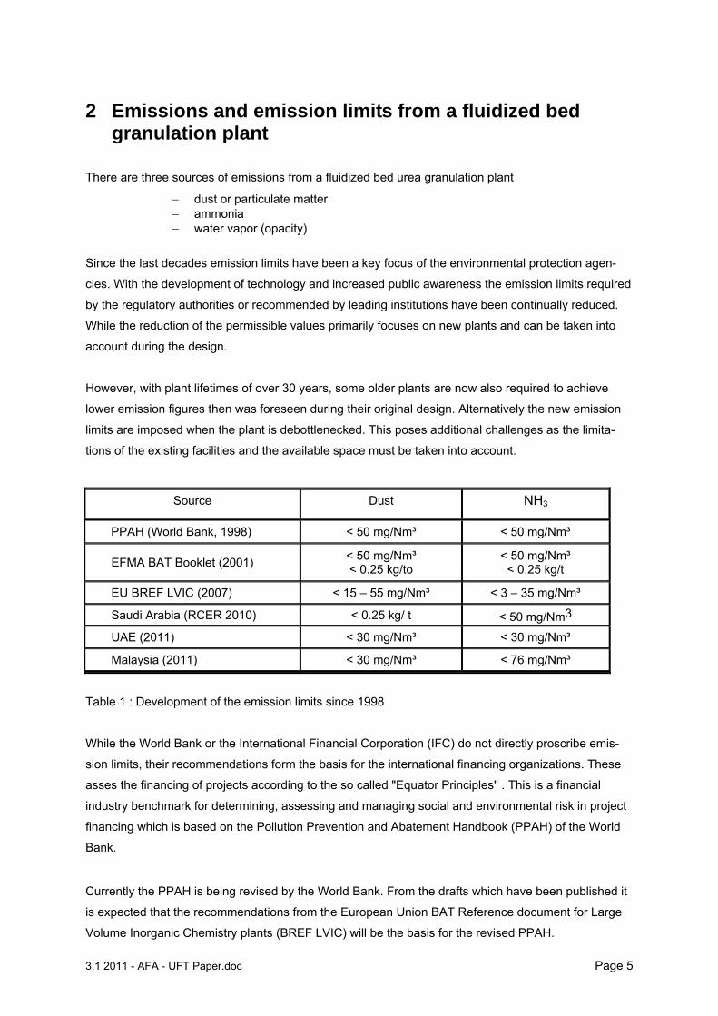
Source Dust NH3
PPAH (World Bank, 1998) < 50 mg/Nm³ < 50 mg/Nm³
EFMA BAT Booklet (2001) < 50 mg/Nm³ < 0.25 kg/to
< 50 mg/Nm³ < 0.25 kg/t
EU BREF LVIC (2007) < 15 – 55 mg/Nm³ < 3 – 35 mg/Nm³
Saudi Arabia (RCER 2010) < 0.25 kg/ t < 50 mg/Nm3
UAE (2011) < 30 mg/Nm³ < 30 mg/Nm³
Malaysia (2011) < 30 mg/Nm³ < 76 mg/Nm³
Table 1 : Development of the emission limits since 1998
While the World Bank or the International Financial Corporation (IFC) do not directly proscribe emis-
sion limits, their recommendations form the basis for the international financing organizations. These
asses the financing of projects according to the so called "Equator Principles" . This is a financial
industry benchmark for determining, assessing and managing social and environmental risk in project
financing which is based on the Pollution Prevention and Abatement Handbook (PPAH) of the World
Bank.
Currently the PPAH is being revised by the World Bank. From the drafts which have been published it
is expected that the recommendations from the European Union BAT Reference document for Large
Volume Inorganic Chemistry plants (BREF LVIC) will be the basis for the revised PPAH.
3.1 2011 - AFA - UFT Paper.doc Page 6
With increasing plant capacities the amount of emitted material from a single source has risen consid-
erably. It is therefore worthwhile to invest in emission reduction systems which return the emitted
material back to the process. However, particularly for ammonia emissions, only a few producers have
taken up the challenge to reduce the emissions drastically. Available emission reduction technologies
often being considered as unattractive or deemed only possible for plants serving a 'closed' market.
3 Dust emissions
The fluidized bed urea granulation plant is a solid-handling process. This means that solid material is
transported and handled. In addition a melt is atomized into fine droplets and injected into the fluidized
bed. All these actions can lead to dust formation and agglomeration. This is common to all granulation
processes and entails that the plant must be cleaned at regular intervals.
Sources of dust :
granulator (80 - 90%) – mostly coarse dust but also some fine dust which is difficult to remove
coolers (10 - 20%) – mostly coarse dust, easy to remove
material handling, in particularly from the crushers – only traces
3.1 Dust emissions control As shown above the operational possibilities to reduce dust emission are limited. Therefore dust
scrubbing systems are standard for fluidized bed urea granulation plants. This is not only due to
environmental reasons but also as a significant amount of product, which would otherwise be lost, is
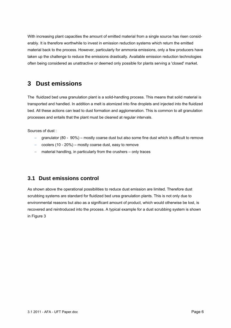
recovered and reintroduced into the process. A typical example for a dust scrubbing system is shown
in Figure 3
3.1 2011 - AFA - UFT Paper.doc Page 7
Figure 3 : Conventional Urea Dust Scrubbing system
As urea is very hygroscopic wet scrubbing systems are preferred. These systems can utilize the
following types of scrubbers :
Vertical scrubbers :
Venturi type scrubbers
Tray type types
Packed bed types, usually with random packing
Horizontal scrubbers
random packing
structured packing
As the dust scrubbing systems are purely water based the reduction in ammonia emissions in such a system in minimal.
4 Ammonia Emissions
The ammonia emitted from the urea granulation plant is to a large extent not generated in the
granulation plant, but enters the granulation plant with the urea solution. The amount of ammonia
contained in the urea solution is the result of the conditions in the evaporation section. The ammonia
is released from the urea solution during the spray of the urea solution into the fluidized bed.
If we assume a typical ammonia concentration in the urea solution of 600 ppm wt the ammonia con-
centration in the off gas is about 130 - 160 mg/Nm³, corresponding to a specific emission of 0.6 -0.7 kg
ammonia per ton urea.
Dust
Scrubbing
Urea granules N > 46 %wt.
NH3 160 mg/Nm³to atm.
Exhaust air with urea dust, NH3
Urea solution tank
Dust recycle
Condensate
Clean Condensate make up
Granulation
Urea Synthesis
Plant Evaporation
3.1 2011 - AFA - UFT Paper.doc Page 8
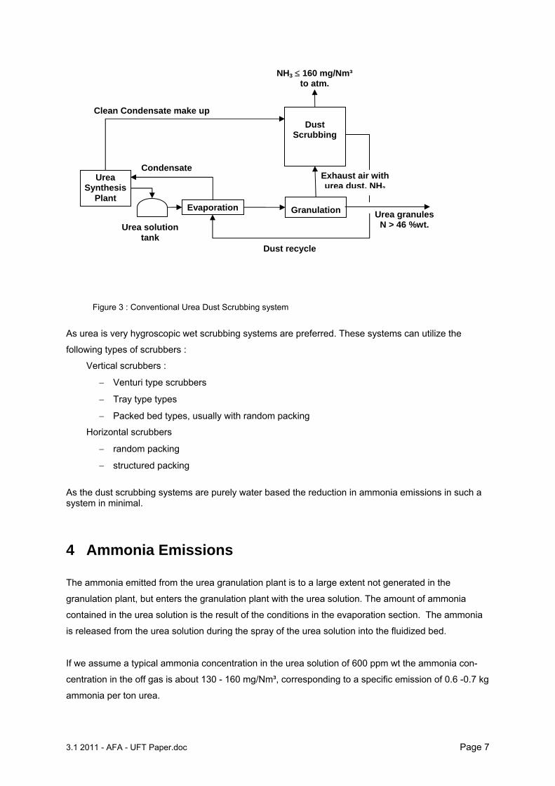
A much smaller amount of NH3 is formed during the formation of biuret in the melt line between urea
solution feed pump and the granulator spray nozzles. During the polymerization of urea to biuret
ammonia is released, as shown in the reaction below.
2 (NH2)2CO NH2C-NH-NH2CO + NH3
Free ammonia from evaporation section ≈ 500 to 600 ppm wt
Ammonia from biuret formation ≈ 90 ppm wt
Total free ammonia at granulator inlet 590 to 690 ppm wt
Free ammonia in final product ≈ 50 ppm wt
Free ammonia released (based on urea solution)
≈ 540 to 640 ppm wt
Table 2 : Sources for ammonia emissions in a fluidized bed urea granulation plant
4.1 Process possibilities to reduce Ammonia emissions (1) The atomization and fluidization air to the granulator effectively ‘strip’ the NH3 contained in the
concentrated urea solution, the NH3 content in the urea solution should therefore be as low as
possible. This can only be done by the adjusting the operating conditions in the urea synthesis and
evaporation units.
(2) The polymerization of urea to biuret releases ammonia, therefore the biuret formation between
evaporation and granulation units must be minimized.
Do not overheat the urea solution to the granulator e.g. high steam pressure on tracing or
jacketing
Reduce residence time of urea solution at elevated temperatures ( > 120°C)
Residence time and biuret content Increase when the capacity of the granulation plant is
reduced
Do not recycle urea solution unnecessarily.
(3) The process water from the melt plant often contains NH3. This water as make-up water for the
scrubbing system of the granulation plant. Any NH3 in the process water will be stripped in the dust
scrubbers and increase the NH3 emissions.
3.1 2011 - AFA - UFT Paper.doc Page 9
5 Ammonia Emission control
With a purely water based scrubbing system the gaseous ammonia released cannot be removed
effectively. The reason is the low solubility of ammonia in water under the prevailing temperature in the
atmospheric scrubber (~ 45°C). As the operational options for the reduction of ammonia emissions
are limited, additional ammonia reduction systems are required to meet the new environmental
legislation.
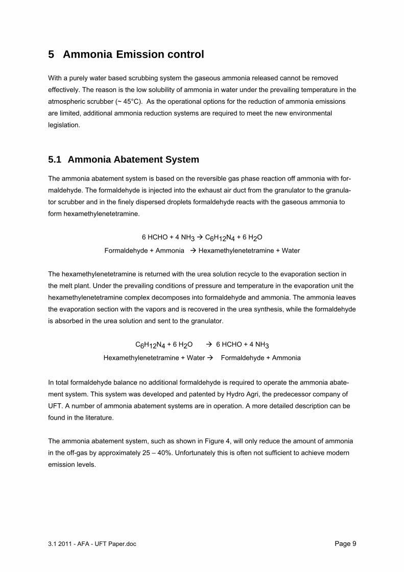
5.1 Ammonia Abatement System The ammonia abatement system is based on the reversible gas phase reaction off ammonia with for-
maldehyde. The formaldehyde is injected into the exhaust air duct from the granulator to the granula-
tor scrubber and in the finely dispersed droplets formaldehyde reacts with the gaseous ammonia to
form hexamethylenetetramine.
6 HCHO + 4 NH3 C6H12N4 + 6 H2O
Formaldehyde + Ammonia Hexamethylenetetramine + Water
The hexamethylenetetramine is returned with the urea solution recycle to the evaporation section in
the melt plant. Under the prevailing conditions of pressure and temperature in the evaporation unit the
hexamethylenetetramine complex decomposes into formaldehyde and ammonia. The ammonia leaves
the evaporation section with the vapors and is recovered in the urea synthesis, while the formaldehyde
is absorbed in the urea solution and sent to the granulator.
C6H12N4 + 6 H2O 6 HCHO + 4 NH3
Hexamethylenetetramine + Water Formaldehyde + Ammonia
In total formaldehyde balance no additional formaldehyde is required to operate the ammonia abate-
ment system. This system was developed and patented by Hydro Agri, the predecessor company of
UFT. A number of ammonia abatement systems are in operation. A more detailed description can be
found in the literature.
The ammonia abatement system, such as shown in Figure 4, will only reduce the amount of ammonia
in the off-gas by approximately 25 – 40%. Unfortunately this is often not sufficient to achieve modern
emission levels.
3.1 2011 - AFA - UFT Paper.doc Page 10
Figure 4 Typical Ammonia Abatement System As can be seen in figure 4 the ammonia abatement system only requires the installation of a small
amount of additional equipment - an additional UF line with a static mixer and a spraying system in the
duct between granulator and dust scrubber. The total amount of formaldehyde does not increase ! The
formaldehyde required according to the product specification is split between the feed to the urea
solution and the scrubber.
5.2 Acidic Scrubbing
While such systems are long established in other fertilizer plants e.g. AN/CAN or DAP/NPK, for urea
plants these systems produce a fundamental problem. The bleed streams from the ammonia reduc-
tion systems introduce foreign components which cannot easily be processed in the NH3 / Urea
complex. These 'new' components, mainly ammonia salts, would cause serious corrosion and other
problems for the urea synthesis unit.
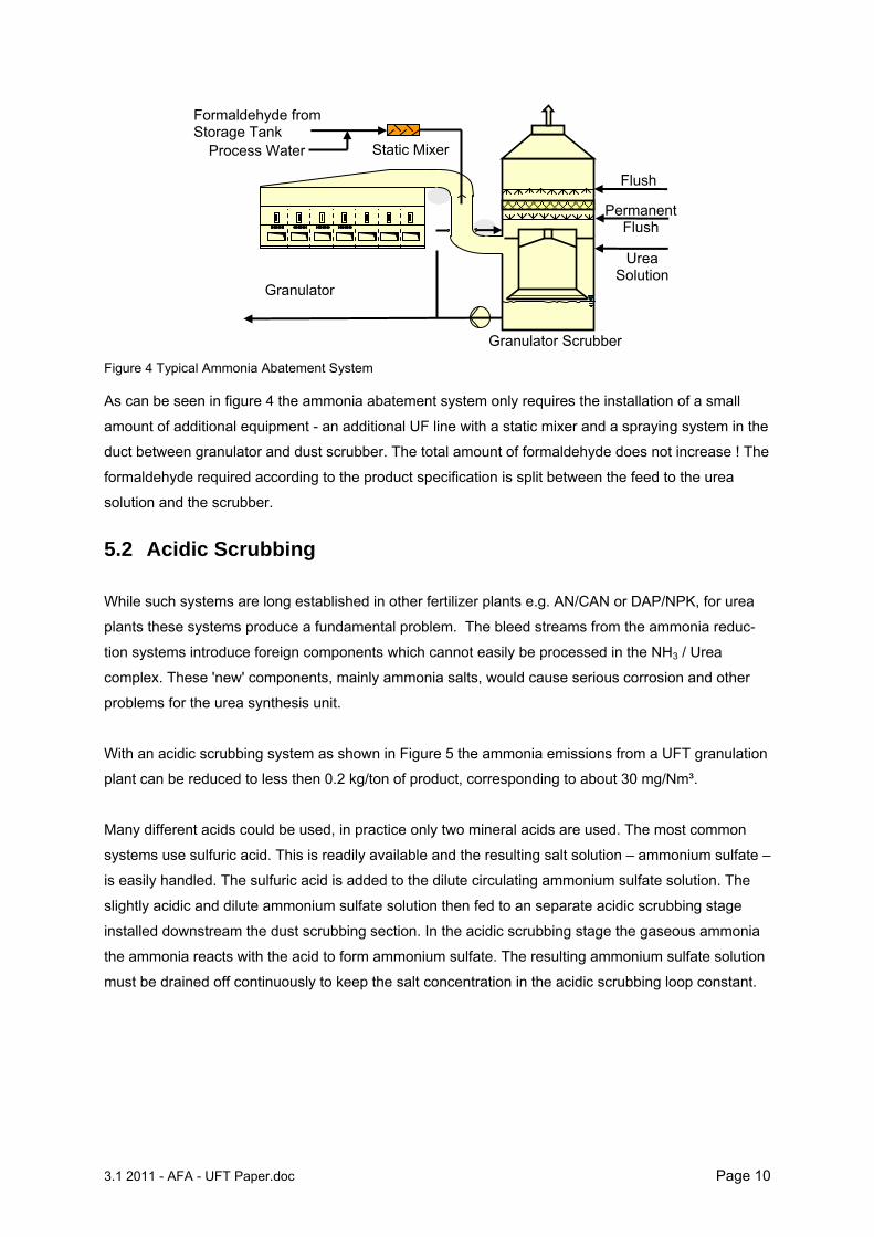
With an acidic scrubbing system as shown in Figure 5 the ammonia emissions from a UFT granulation
plant can be reduced to less then 0.2 kg/ton of product, corresponding to about 30 mg/Nm³.
Many different acids could be used, in practice only two mineral acids are used. The most common
systems use sulfuric acid. This is readily available and the resulting salt solution – ammonium sulfate –
is easily handled. The sulfuric acid is added to the dilute circulating ammonium sulfate solution. The
slightly acidic and dilute ammonium sulfate solution then fed to an separate acidic scrubbing stage
installed downstream the dust scrubbing section. In the acidic scrubbing stage the gaseous ammonia
the ammonia reacts with the acid to form ammonium sulfate. The resulting ammonium sulfate solution
must be drained off continuously to keep the salt concentration in the acidic scrubbing loop constant.
Granulator
Granulator Scrubber
Flush
Permanent Flush
Urea Solution
Static Mixer
Formaldehyde from Storage Tank
Process Water
3.1 2011 - AFA - UFT Paper.doc Page 11
Figure 5 - Typical Acidic Scrubbing System
An alternative to sulfuric acid is nitric acid. The efficiency and the process is the same, but there is a
safety issue. Apart from dealing with dilute ammonium nitrate solution there is the danger that at low
pH the nitric acid and urea react to form urea nitrate. Urea nitrate is highly explosive. Therefore special
attention must be given to control the pH of the acidic scrubbing section. In addition great care must
be taken to prevent dead – spots in the equipment and piping where nitrate containing material could
crystallize and accumulate.
Basically the same safety requirements as are required for the handling of dilute ammonium nitrate
solutions must be implemented. These require special pump designs, additional instrumentation and
washing facilities that ensure that all traces of nitrate containing material are flushed from the
scrubbing system thereby preventing any accumulation of nitrate material, e.g. in areas of the
scrubber system which are not wetted continuously.
Ammonium sulfate can be used as a liquid fertilizer, as a feed stock in a NPK plant or crystallized. The
nitric acid option is usually only feasible for sites which have a nitric acid / ammonium nitrate facilities.
In this case the ammonium nitrate solution can be sent to the ammonium nitrate plant, e.g. for
producing UAN solution.
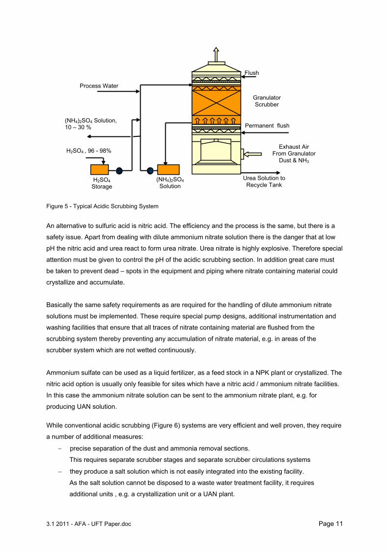
While conventional acidic scrubbing (Figure 6) systems are very efficient and well proven, they require
a number of additional measures:
precise separation of the dust and ammonia removal sections.
This requires separate scrubber stages and separate scrubber circulations systems
they produce a salt solution which is not easily integrated into the existing facility.
As the salt solution cannot be disposed to a waste water treatment facility, it requires
additional units , e.g. a crystallization unit or a UAN plant.
Flush
Permanent flush
Urea Solution to Recycle Tank
Process Water
(NH4)2SO4 Solution, 10 – 30 %
H2SO4 , 96 - 98%
H2SO4
Storage (NH4)2SO4 Solution
Granulator Scrubber
Exhaust Air From Granulator
Dust & NH3
3.1 2011 - AFA - UFT Paper.doc Page 12
Figure 6 Conventional Acidic Scrubbing System
5.3 Ammonia Convert Technology
The objectives for the development of the UFT proprietary Ammonia Convert Technology were:
Reduction of ammonia emission by at least 80%
System to be simple and reliable
No side stream of scrubbing solution of acidic scrubber
No contamination of the urea synthesis with ammonia salts
Overall economics to be feasible
Based on these objectives and the experience gained from acidic scrubbing systems, the scheme
shown in Figure 7 has been developed.
In the granulation plant in additional acidic scrubber stage is installed downstream of the dust scrub-
ber. This is to ensure that only a nearly dust free gas flow enters the acidic scrubbing stage. Otherwise
the urea would be decomposed by the acid. The ammonia is absorbed in the acidic scrubbing system
and is converted into ammonium sulfate.
The bleed of the combined scrubbing system is sent to a small evaporation unit, consisting of a single
stage vacuum evaporator. In this small evaporation unit the urea solution containing the ammonium
salt is concentrated up to the urea content required for granulation and is subsequently mixed with the
'fresh' urea solution coming from the vacuum evaporation unit of the urea synthesis plant.
Dust Scrubbing
NH3 30 mg/Nm³to atm.
Exhaust air with urea dust, NH3
Urea solution tank
Condensate
H2SO4 Feed
Granulation
Urea Synthesis
Plant Evaporation
Acidic Scrubbing
Condensate make up
Ammonium Sulphate Solution
10 - 30 %wt.
3.1 2011 - AFA - UFT Paper.doc Page 13
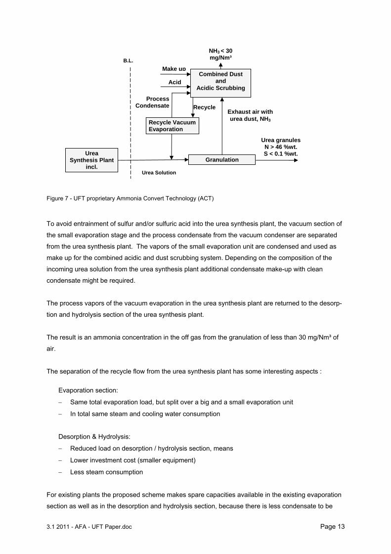
Figure 7 - UFT proprietary Ammonia Convert Technology (ACT)
To avoid entrainment of sulfur and/or sulfuric acid into the urea synthesis plant, the vacuum section of
the small evaporation stage and the process condensate from the vacuum condenser are separated
from the urea synthesis plant. The vapors of the small evaporation unit are condensed and used as
make up for the combined acidic and dust scrubbing system. Depending on the composition of the
incoming urea solution from the urea synthesis plant additional condensate make-up with clean
condensate might be required.
The process vapors of the vacuum evaporation in the urea synthesis plant are returned to the desorp-
tion and hydrolysis section of the urea synthesis plant.
The result is an ammonia concentration in the off gas from the granulation of less than 30 mg/Nm³ of
air.
The separation of the recycle flow from the urea synthesis plant has some interesting aspects :
Evaporation section:
Same total evaporation load, but split over a big and a small evaporation unit
In total same steam and cooling water consumption
Desorption & Hydrolysis:
Reduced load on desorption / hydrolysis section, means
Lower investment cost (smaller equipment)
Less steam consumption
For existing plants the proposed scheme makes spare capacities available in the existing evaporation
section as well as in the desorption and hydrolysis section, because there is less condensate to be
Combined Dust and
Acidic Scrubbing
Urea granules N > 46 %wt.
S < 0.1 %wt.
Exhaust air with urea dust, NH3
ProcessCondensate
Urea Synthesis Plant
incl.
Acid
NH3 < 30 mg/Nm³
Make up
Recycle
Granulation
Urea Solution
B.L.
Recycle Vacuum Evaporation
3.1 2011 - AFA - UFT Paper.doc Page 14
treated. The spare capacity gained is about 15% of the total plant capacity. So the ammonia convert
technology is an excellent revamp option.
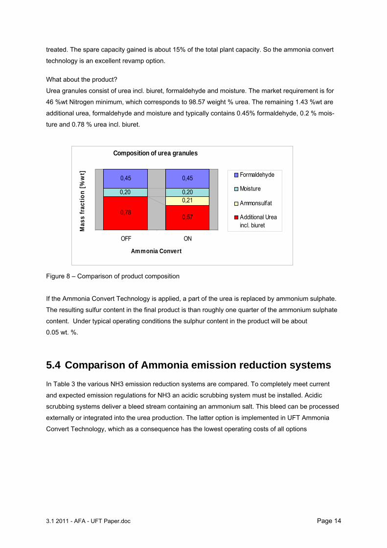
What about the product?
Urea granules consist of urea incl. biuret, formaldehyde and moisture. The market requirement is for
46 %wt Nitrogen minimum, which corresponds to 98.57 weight % urea. The remaining 1.43 %wt are
additional urea, formaldehyde and moisture and typically contains 0.45% formaldehyde, 0.2 % mois-
ture and 0.78 % urea incl. biuret.
Composition of urea granules
0,57
0,210,20
0,45 0,45
0,78
0,20
OFF ON
Ammonia Convert
Mas
s fr
acti
on
[%
wt] Formaldehyde
Moisture
Ammonsulfat
Additional Ureaincl. biuret
Figure 8 – Comparison of product composition
If the Ammonia Convert Technology is applied, a part of the urea is replaced by ammonium sulphate.
The resulting sulfur content in the final product is than roughly one quarter of the ammonium sulphate
content. Under typical operating conditions the sulphur content in the product will be about
0.05 wt. %.
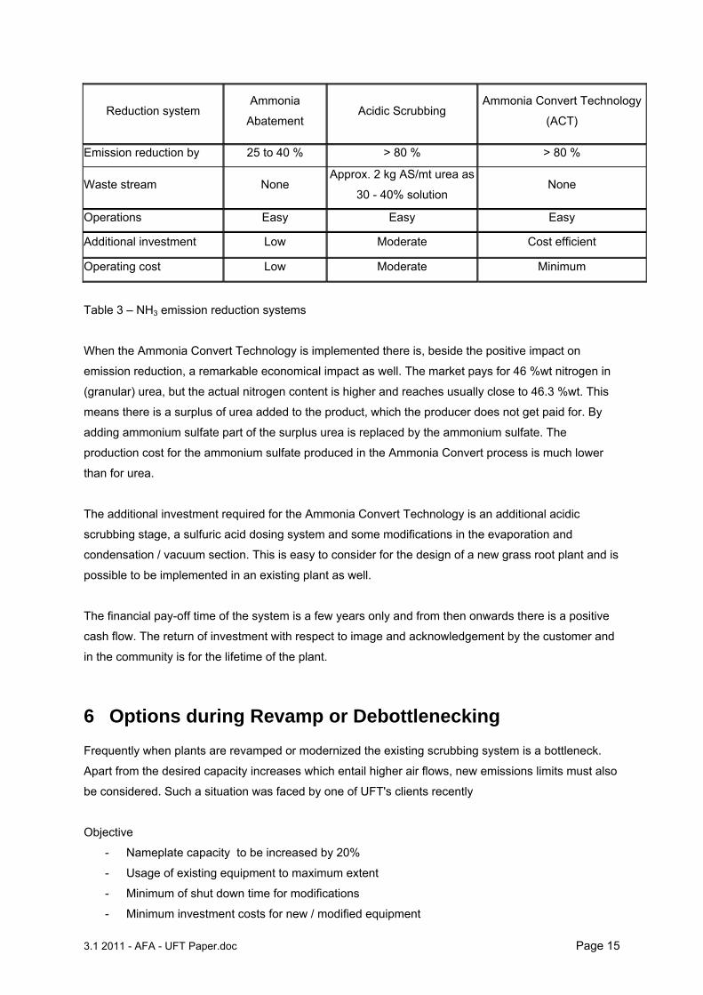
5.4 Comparison of Ammonia emission reduction systems In Table 3 the various NH3 emission reduction systems are compared. To completely meet current
and expected emission regulations for NH3 an acidic scrubbing system must be installed. Acidic
scrubbing systems deliver a bleed stream containing an ammonium salt. This bleed can be processed
externally or integrated into the urea production. The latter option is implemented in UFT Ammonia
Convert Technology, which as a consequence has the lowest operating costs of all options
3.1 2011 - AFA - UFT Paper.doc Page 15
Reduction system Ammonia
Abatement Acidic Scrubbing
Ammonia Convert Technology
(ACT)
Emission reduction by 25 to 40 % > 80 % > 80 %
Waste stream None Approx. 2 kg AS/mt urea as
30 - 40% solution None
Operations Easy Easy Easy
Additional investment Low Moderate Cost efficient
Operating cost Low Moderate Minimum
Table 3 – NH3 emission reduction systems
When the Ammonia Convert Technology is implemented there is, beside the positive impact on
emission reduction, a remarkable economical impact as well. The market pays for 46 %wt nitrogen in
(granular) urea, but the actual nitrogen content is higher and reaches usually close to 46.3 %wt. This
means there is a surplus of urea added to the product, which the producer does not get paid for. By
adding ammonium sulfate part of the surplus urea is replaced by the ammonium sulfate. The
production cost for the ammonium sulfate produced in the Ammonia Convert process is much lower
than for urea.
The additional investment required for the Ammonia Convert Technology is an additional acidic
scrubbing stage, a sulfuric acid dosing system and some modifications in the evaporation and
condensation / vacuum section. This is easy to consider for the design of a new grass root plant and is
possible to be implemented in an existing plant as well.
The financial pay-off time of the system is a few years only and from then onwards there is a positive
cash flow. The return of investment with respect to image and acknowledgement by the customer and
in the community is for the lifetime of the plant.
6 Options during Revamp or Debottlenecking Frequently when plants are revamped or modernized the existing scrubbing system is a bottleneck.
Apart from the desired capacity increases which entail higher air flows, new emissions limits must also
be considered. Such a situation was faced by one of UFT's clients recently
Objective
- Nameplate capacity to be increased by 20%
- Usage of existing equipment to maximum extent
- Minimum of shut down time for modifications
- Minimum investment costs for new / modified equipment
3.1 2011 - AFA - UFT Paper.doc Page 16
- No compromise on product quality and environmental aspects
Problems:
- Layout restrictions for new / exchanged equipment
- Steel and concrete structure restrictions
- Increased pressure drop of scrubbers due to requirement of higher fluidization air flows
- Limited spare capacity of major rotating equipment, especially scrubber exhaust fans
Approach:
- Enlargement of static equipment to the optimum usage of available space inside the building
considering refined distribution of cooling duties
- Replacing the internals of the existing high pressure drop Venturi-type scrubbers with two
stages of low pressure drop structured packing type.
The use of the structured packing reduced the pressure drop of the existing scrubber to about 1/3 of
the original value. In this case the new increased air flow can be handled by the existing scrubber and
the existing scrubber exhaust fan.
The new internals are arranged in two stages, therefore one stage could be used for a acidic
scrubbing if required at a latter stage.
7 Summary The ammonia emission reduction technologies available have all one or another draw back. Either the
achievable reduction is limited (ammonia abatement system) or a waste stream is generated, which
can not be treated economically in a stand alone ammonia/urea complex
The proposed Ammonia Convert Technology is based on an acidic scrubbing stage and a recycle of
the obtained ammonium salt into the final product. This allows reduction of ammonia emission to very
low levels, while at the same time avoiding an unwanted liquid waste stream.
The Ammonia Convert Technology is beneficial to the environment as it reduces ammonia emissions
drastically. At the same time production cost for granular urea can be reduced. Finally a urea fertilizer
as produced, which gives added value to the consumers due to the content of micro nutrients while
still supplying a nitrogen content of min. 46 %wt.
3.1 2011 - AFA - UFT Paper.doc Page 17
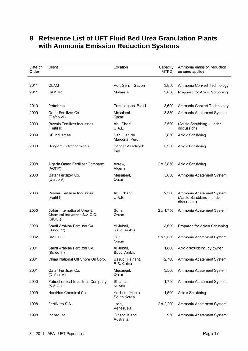
8 Reference List of UFT Fluid Bed Urea Granulation Plants with Ammonia Emission Reduction Systems
Date of Order
Client Location Capacity(MTPD)
Ammonia emission reduction scheme applied
2011 OLAM Port Gentil, Gabon 3,850 Ammonia Convert Technology
2011 SAMUR Malaysia 3,850 Prepared for Acidic Scrubbing
2010 Petrobras Tres Lagoas, Brazil 3,600 Ammonia Convert Technology
2009 Qatar Fertilizer Co. (Qafco VI)
Mesaieed, Qatar
3,850 Ammonia Abatement System
2009 Ruwais Fertilizer Industries (Fertil II)
Abu Dhabi U.A.E.
3,500 (Acidic Scrubbing – under discussion)
2009 CF Industries San Juan de Marcona, Peru
3,850 Acidic Scrubbing
2009 Hengam Petrochemicals Bandar Assaluyeh, Iran
3,250 Acidic Scrubbing
2008 Algeria Oman Fertilizer Company (AOFP)
Arzew, Algeria
2 x 3,850 Acidic Scrubbing
2008 Qatar Fertilizer Co. (Qafco V)
Mesaieed, Qatar
3,850 Ammonia Abatement System
2006 Ruwais Fertilizer Industries (Fertil I)
Abu Dhabi U.A.E.
2,500 Ammonia Abatement System (Acidic Scrubbing – under discussion)
2005 Sohar International Urea & Chemical Industries S.A.O.C. (SIUCI)
Sohar, Oman
2 x 1,750 Ammonia Abatement System
2003 Saudi Arabian Fertilizer Co. (Safco IV)
Al Jubail, Saudi Arabia
3,600 Prepared for Acidic Scrubbing
2002 OMIFCO Sur, Oman
2 x 2,530 Ammonia Abatement System
2001 Saudi Arabian Fertilizer Co. (Safco III)
Al Jubail, Saudi Arabia
1,800 Acidic scrubbing, by owner
2001 China National Off Shore Oil Corp. Basuo (Hainan), P.R. China
2,700 Ammonia Abatement System
2001 Qatar Fertilizer Co. (Qafco IV)
Mesaieed, Qatar
3,500 Ammonia Abatement System
2000 Petrochemical Industries Company (K.S.C.)
Shuaiba, Kuwait
1,750 Ammonia Abatement System
1999 NamHae Chemical Co. Yochon, (Yosu) South Korea
1,500 Acidic Scrubbing
1998 FertiNitro S.A. Jose, Venezuela
2 x 2,200 Ammonia Abatement System
1998 Incitec Ltd. Gibson Island Australia
950 Ammonia Abatement System
3.1 2011 - AFA - UFT Paper.doc Page 18
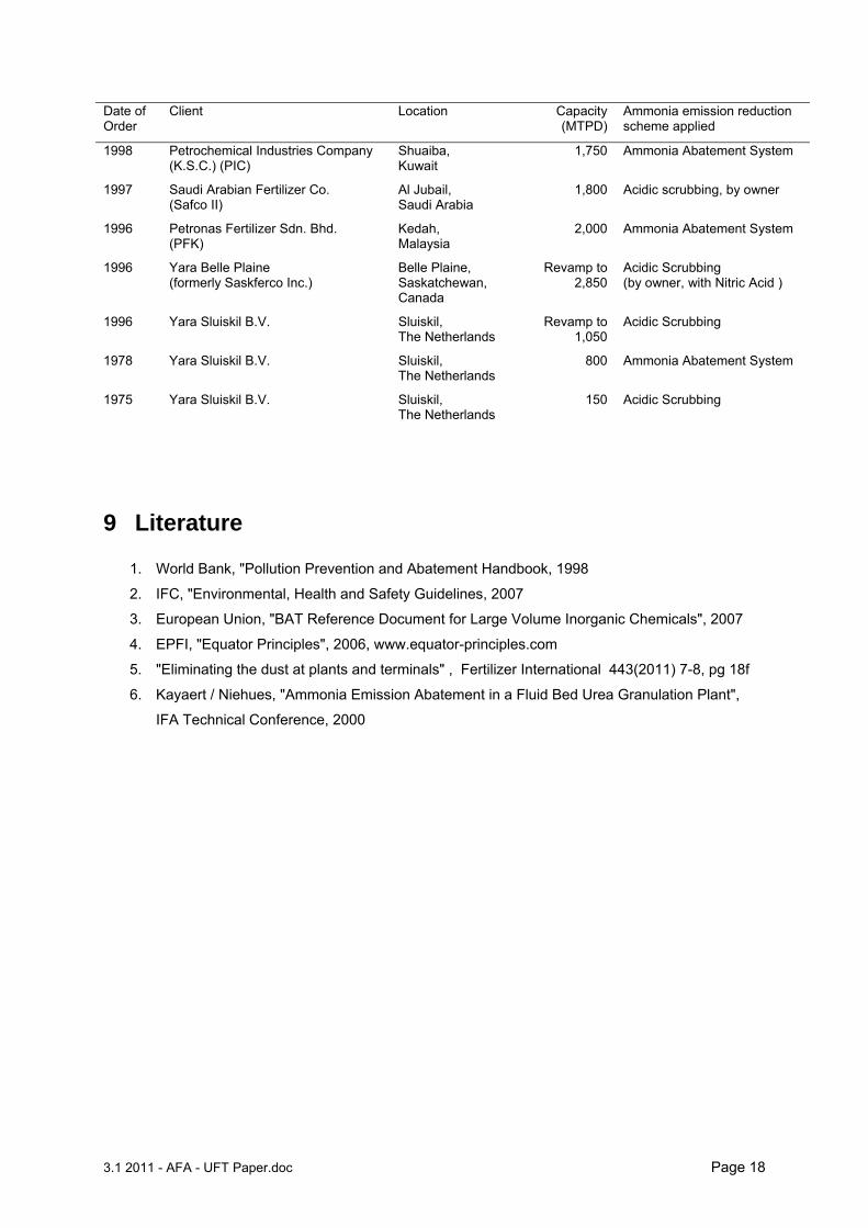
Date of Order
Client Location Capacity(MTPD)
Ammonia emission reduction scheme applied
1998 Petrochemical Industries Company (K.S.C.) (PIC)
Shuaiba, Kuwait
1,750 Ammonia Abatement System
1997 Saudi Arabian Fertilizer Co. (Safco II)
Al Jubail, Saudi Arabia
1,800 Acidic scrubbing, by owner
1996 Petronas Fertilizer Sdn. Bhd. (PFK)
Kedah, Malaysia
2,000 Ammonia Abatement System
1996 Yara Belle Plaine (formerly Saskferco Inc.)
Belle Plaine, Saskatchewan, Canada
Revamp to2,850
Acidic Scrubbing (by owner, with Nitric Acid )
1996 Yara Sluiskil B.V. Sluiskil, The Netherlands
Revamp to1,050
Acidic Scrubbing
1978 Yara Sluiskil B.V. Sluiskil, The Netherlands
800 Ammonia Abatement System
1975 Yara Sluiskil B.V. Sluiskil, The Netherlands
150 Acidic Scrubbing
9 Literature
1. World Bank, "Pollution Prevention and Abatement Handbook, 1998
2. IFC, "Environmental, Health and Safety Guidelines, 2007
3. European Union, "BAT Reference Document for Large Volume Inorganic Chemicals", 2007
4. EPFI, "Equator Principles", 2006, www.equator-principles.com
5. "Eliminating the dust at plants and terminals" , Fertilizer International 443(2011) 7-8, pg 18f
6. Kayaert / Niehues, "Ammonia Emission Abatement in a Fluid Bed Urea Granulation Plant",
IFA Technical Conference, 2000


