Embed Size (px)
Citation preview

PRIMA
© - ALSTOM 2013. All rights reserved. Information contained in this document is indicative only. No representation or warranty is given or should be relied on that it
is complete or correct or will apply to any particular project. This will depend on the technical and commercial circumstances. It is provided without liability and is
subject to change without notice. Reproduction, use or disclosure to third parties, without express written authority, is strictly prohibited.
Technical Data
Plug-in rapid-wire integrated
Publication Reference: PRIMA/EN TD/B


PRIMA
512
PRIMA: Plug-in rapid-wire integrated multi-mount auxiliary relays
Features
• Compact design – 12 relays per 19 inch rack
• Wide operative voltage range
• Optional test feature
• Self-reset flag as standard
• Optional timer
• Built-in snap lock feature automatically locks the relay to its socket
• Unique terminal design ensures rapid wiring – (time saving of up to 75%)
• Choice of two types of terminal
• DIN rail, panel or rack mounting
• Simple mechanical coding for relay to socket connection
• Manufactured from flame-retardant materials
Models Available
• PRE electrical reset relays
• PRH hand/electrical reset relays
• PRS self reset relays
ApplicationPrima, is a compact, voltage-operated,attracted armature auxiliary relay withinstantaneous and time delayed auxiliaryfunctions. It has been designed to fulfil theneed for contact multiplication inprotection and control environments, froma brief developed as a result of worldwidemarket studies. Great emphasis has beenplaced on making it as easy as possible tospecify, order, configure and install.
Figure 1 Relay and cross section of socket shown actual size
Captive nut
Wireplaced on
screw
Relaycontacts
Relayconnector Snap lock
featureCoding
plugSnap lock
feature

PRIM
A
513
Description
Ease of installation is ensured by thetwo-part design in which the relay plugsinto a socket which may be specifiedwith front or rear connected terminals. Asnaplock feature between relay andsocket, eliminates the need for separatewire clips. The front-connected socket,mainly for DIN rail mounting, mayalternatively be mounted on a solidpanel via a single fixing screw, whilst therear- connected design clips or screwfixes to suitable panel cut-outs or may beaccommodated on a special rackmounting frame.
The two types of terminal availableinclude a unique captive nut designwhich makes for wiring time reductionsof up to 75%.
The relays are available as either self-reset, electrical reset or hand/electricalreset types. The range includes amechanical operation indicator asstandard and an optional integratedtimer to minimise panel spacerequirements.
All the contacts are changeover type,designed to the latest IEC 255 standards,ensuring maximum flexibility withsimplified ordering.
Relay
Contacts
Self reset (PRS) models have 4changeover contacts except those withdelayed drop-off timer which have only3 contacts. Hand/electrical reset models(PRH) and electrical reset models (PRE)have 3 changeover contacts. All havesilver contact tips to provide long lifeand reliability over a wide range ofduties.
Optional magnetic blow-out contacts arerecommended for heavy or highlyinductive loads.
See Technical Data for contact ratings.
Operation indicators
All relays are fitted with an operationindicator that follows the contactoperation, with the exception of self-resetting instantaneous relays type PRSwhich, when required, can be fitted witha hand reset indicator.
Test/reset buttons
Relays other than the electrical resetmodel are available with an optional testbutton to check contact and followingindicator operation.
A reset button is fitted on all modelsexcept the electrical reset and self resetrelays with a following flag.
Both test and reset buttons are flush withthe cover and cannot be accidentallyoperated.
Time delays
The dc self-reset relays can be fitted withadjustable timers for delayed operationor delayed reset. These have a widerange, from 0.1 to 270s, to be set by thecustomer in 4 ranges with overlappingadjustment. By installing rectifier typePA01 in series with a dc relay, timedelayed relays can be used on acsupplies. Timers are supplied set to theirminimum values.
The controls are behind a hinged cover.Adjustment is by screwdriver, see Figure2. The rotary switch, on the right handside, allows the customer to select from 4timing ranges. The trimpot is then usedfor adjustment within the time rangeselected, (see Technical Data).
The cover has provision for the customerto affix an identification label.
Figure 2 Timer control adjustment
Figure 3 Operation of relay to socket coding
Relaycodingplug
5. Push assembly home6. Insert relay into socket
1. Insert relay plug (part way)2. Rotate plug anti-clockwise3. Pull assembly out (3mm)
4. Rotate assembly to achieve the desired setting
PRIMA
514
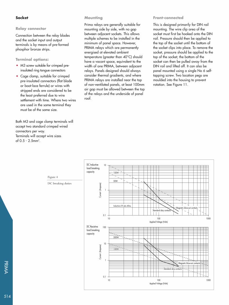
Socket
Relay connector
Connection between the relay bladesand the socket input and outputterminals is by means of pre-formedphosphor bronze strips.
Terminal options:• M3 screw suitable for crimped pre-
insulated ring tongue connectors
• Cage clamp, suitable for crimpedpre-insulated connectors (flat bladeor boot-lace ferrule) or wires withstripped ends are considered to bethe least preferred due to wiresettlement with time. Where two wiresare used in the same terminal theymust be of the same size.
Both M3 and cage clamp terminals willaccept two standard crimped wiredconnectors per way. Terminals will accept wire sizes of 0.5 - 2.5mm2.
Mounting
Prima relays are generally suitable formounting side by side, with no gapbetween adjacent sockets. This allowsmultiple schemes to be installed in theminimum of panel space. However,PRIMA relays which are permanentlyenergised at elevated ambienttemperature (greater than 40°C) shouldhave a vacant space, equivalent to thewidth of one PRIMA, between adjacentrelays. Panels designed should alwaysconsider thermal gradients, and wherePRIMA relays are installed near the topof non-ventilated panels, at least 100mmair gap must be allowed between the topof the relays and the underside of panelroof.
Front-connected
This is designed primarily for DIN railmounting. The wire clip area of thesocket must first be hooked onto the DINrail. Pressure should then be applied tothe top of the socket until the bottom ofthe socket clips into place. To remove thesocket, pressure should be applied to thetop of the socket; the bottom of thesocket can then be pulled away from theDIN rail and lifted off. It can also bepanel mounted using a single No 6 self-tapping screw. Two location pegs aremoulded into the housing to preventrotation. See Figure 11.
100
10
1
0.110 100 1000
Applied Voltage (Volts)
100Applied Voltage (Volts)
Curre
nt (A
mper
es)
500W
Magnetic blow-out contacts
Standard duty contacts
DC Resistiveload breakingcapacity
100W
10
0.110 1000
1
Curre
nt (A
mper
es) 50W
Inductive L/R ratio 40ms.Magnetic blow-out contacts
Standard duty contacts
DC Inductiveload breakingcapacity 100W
Figure 4
DC breaking duties

PRIM
A
515
Rear-connected
This is designed to be rack mounted using the clip-on mounting featureas follows: The wire clip area of the socket must be placed on the rackfirst, and pressure should then be applied to the top of the socket untilit clips into place. To remove the socket, apply pressure to the top of thesocket and push away from the rack. Alternatively, it may be panelmounted using two No 6 self-tapping screws or the clip-on mountingfeature as described above. The socket can then be lifted from the rack. See Figure 10 for details of the required cut-outs.
A custom designed 483mm (19 inch) rack is available into which 12relays will fit. See Figure 9 for rack assembly and blanking platedetails.
Relay to socket coding
A simple mechanical relay to socket coding system offering twelvecombinations is employed to prevent the relay being plugged into thewrong socket.
See Figure 3.
Contact wetting
In SCADA or alarm applications, the minimum recommended "wetting"values to ensure reliable making of contacts are 24V and 0.5VA.Where PRiMA relays are installed such that breaking of contacts willinitiate the alarm, it is recommended that the SCADA has an alarminitiation delay of at least 2ms.
This prevents spurious alarming when cubicle doors are closed, andcontinuity may be broken for a fleeting instant due to the transmittedmechanical shock.
In the most onerous application of relays being mounted directly onswing-frame cubicle doors, it is strongly recommended that any "breakto alarm" circuits utilise 1VA load for better contact wetting.
Rectifier Units
A PA01 rectifier unit may be used with relays with timer or the
24/27V rated relays to allow their use on ac supplies. The PA01 ishoused in a standard Prima case and must be used in conjunction witha socket suitable for the application.
Figure 5 Type PRS – Instantaneous self reset relay
Figure 6 Type PRS – Self reset relay with time delayed operation
+ —
A1 A2
11 21 31 41
12 22 32 42
14 24 34 44
ZG1074
A2A1
Initiatecontact
1073 1
Rear connected socketterminal layout
Front connected socketterminal layout
Viewed from rearViewed from front
Vx
RL14
42 32 22 12
41 31 21
A2 A1
11
44 34 24 14
121411
222421
323431
424441
Output contactsBreak 12 22 32 42Make 14 24 34 44Common + 11 21 31 41
+ —
42 32 22 12
41 31 21
A2 A1
A1 A211
11 21 31 41
44 34 24 14 12 22 32 42
14 24 34 44
121411
222421
323431
424441
ZG1078
A2A1
Initiatecontact
10731
Rear connected socketterminal layout
Front connected socketterminal layout
Viewed from rearViewed from front
Output contactsBreak 12 22 32 42Make 14 24 34 44Common + 11 21 31 41
Vx
RL14
xtsecs

PRIMA
516
Figure 10 Types PRS and PA – Self reset ac relay
with time delayed reset
The polarity indicated for the output contacts is recommended where magnetic blow-out contacts are used.
Figure 7 Type PRS – Self reset relay with time delayed reset Figure 8 Types PRH – Hand and electrically reset andPRE – Electrically reset
+ —
42 32
41 31
A2 A1
A1 A211
44 12
ZG1078
A2A1
14
Initiatecontact
1076 1 3
Rear connected socketterminal layout
Front connected socketterminal layout
Viewed from rearViewed from front
121411
222421
323431
424441
Output contacts
Break 22Make 24 Common + 21
xtsecs
Vx
RL13
+ —
A2 A1
A1 A211
ZG1074
A1 76 5 3 1
10
14
Rear connected socketterminal layout
Front connected socketterminal layout
Viewed from rearViewed from front
121411
222421
323431
424441
Output contacts
Vx
RL13
A2Operate
Reset
Figure 9 Types PRS and PA – Self reset ac relay with time delayed operation
A11
+ —
A23
Vx
RL14
121411
222421
323431
424441
+
A1 A2
Rear connected socketterminal layout
Front connected socketterminal layout
Viewed from rearViewed from front
41 31 21
A2 A1
11
Output contacts
BreakMakeCommon
xtsecs
A1 A2
32 22ExternalAC Unit
PA01
A11
—
A23
+Vx
RL13
121411
222421
323431
424441
+
A1 A2
Rear connected socketterminal layout
Front connected socketterminal layout
Viewed from rearViewed from front
21
A2 A1
11
Output contacts
xtsecs
A1 A2
32 22ExternalAC Unit
PA01
6Initiate
Contact
14
InitiateContact
34 24 14
22 12
21
22 32 42
24 14 34 44
11 21 31 41
34 44 41
42 32
31
44 24 14 34
42 32 22 12
12 22 32 42
14 24 34 44
11 21 31 41
12 22 32 42 14 24 34 44 11 21 31 41
14
22 24 21
32 34 31
42 44 41
BreakMakeCommon
41 31
44 34
32 22 12 42
24 14 12
14
11
22 32 42
24 34 44
21 31 41
22 24 21
32 34 31
42
44 41
BreakMake
Common
41 31
44 34
32 42 44
42
34
12
14
11
22 32 24
21
31
12
14
21 41
24 22

PRIM
A
517
Technical Data
RatingsAll models are for ac/dc operation except for the following which are dc only:
• self reset relays with timers
• 24/27V hand/electrical reset models
The use of rectifier unit PA01 will allow all dc only models to be used on ac supplies.
Standard coil ratings 24/27V, 30/34V, 48/54V,110/125V, 220/250V
PA01 24/250V ac
Operative ranges Voltage Continuous Maximumrating operating DC + peak (V) voltage ripple
range (V) voltage
24/27 19 - 32.4 35.5V30/34 24 - 41 45V48/54 37.5 - 65 71.5V110/125 87.5 - 150 165V220/250 175 - 275 330V
Frequency 50/60Hz
Burdens Operate Reset/timing
(specified at lower rated voltage) DC(W) AC(VA) DC(W) AC(VA)Self reset <3 <3 n/a n/aHand/electrical reset <4 <4 <12* <12Self-reset timer - DPU <4 n/a <1 n/aSelf-reset timer - DDO <4 n/a <3 n/a
*Cut-off after approximately 30ms.
Operating timeFor a normally open contact to 30ms typically for ac operated relaysclose at lower rated voltage 25ms typically for dc operated relays
Reset timeFor a normally closed contact to reset <100ms typically
Timer range (seconds)
The timer ranges shown here are approximate, and for the lower rated voltage
Switch position DPU mode DDO mode1 0.10 - 0.15 0.10 - 0.202 0.13 - 1.6 0.18 - 2.03 1.0 - 17.0 1.2 - 20.04 16.0 - 270.0 16.0 - 270.0
Note1: Timer setting instructions on reverse of blank identification labels provided witheach relay.
Note 2: Adjustments to the potentiometer and switch should be made using an insulatedtool.

PRIMA
518
Repeatability ±2%
Variation of timing over the operative voltage range
±15% or 20ms whichever is the greater
Variation of timing withtemperature over the operative temperature range ±10% or 20ms whichever is
the greater
ContactsAll relay types are fitted with changeover contacts (break before make) only. The number of contacts available for customer use varies with relay type. See Figures 5 - 8.
Number of output contactsSelf reset relay 4Hand /electrical reset relay 3Electrical reset relay 3Self reset timer - DPU 4Self reset timer - DDO 3
Contact ratingsContact Current Make and carry Make and Breaktype continuously carry for 3sStandard AC 1250VA with 7500VA with 1250VA with
maxima of 10A maxima of 30A maxima ofand 300V and 300V 10A and 300V
DC 1250W with 7500W with 120W (resistive)maxima of 10A maxima of 30A 30W* (inductive)and 300V and 300V at 100V.
L/R = 40msSee Figure 4for curves
Magnetic DC 1250W with 7500W with 350W (resistive)blow-out maxima of 10A maxima of 30A 50W* (inductive)
and 300V and 300V at 100V.
L/R = 40msSee Figure 4for curves
* Normally closed contacts breaking with positive potential applied tothe moving contacts
Contacts in use Continuous rating per contact (amps)1 102 103 54 5
Maximum rate of operation, 600 per hour
Durability Loaded contact 100,000 operationsUnloaded contact 1,000,000 operations

PRIM
A
519
High voltage withstandDielectric withstand
IEC 60255-5: 1977 2kV rms for 1 minute between allterminals and case earth. 2kV rms for 1 minute between terminals of independent circuits including contact circuits, with terminals on each independent circuit connected together. 1kV rms for 1 minute across open contacts of output relays.
ANSI/IEEEC37.90:1989 1.5kV rms across open outgoing
contact pairs.
High voltage impulseIEC 60255-5:1977 Three positive and three negative
impulses of 5kV peak, 1.2/50 µs, 0.5J between all independent circuits andbetween all terminals and earth.
Insulation resistanceIEC 60255-5:1977 >100MV when measured at 500V dc
Electrical environmentDC supply interruptionIEC 60255-11:1979 The unit will withstand a 10ms
interruption in the auxiliary supply, under normal operating conditions,without de-energising.
High frequency disturbances
IEC 60255-22-1:1988 Class III 2.5kV peak between independentcircuits and case.1.0kV peak across terminals of the same circuit.
Fast transient disturbanceIEC 60255-22-4: 1992 Class IV Applied directly to auxiliary supply.
EMC Compliance89/336/EEC Compliance to the European Commission
Directive on EMC is claimed via the Technical Construction File route.
EN 50081-2:1994 Generic Standards were used to establish EN 50082-2:1995 conformity.
Product safety72/23/EEC Compliance with the European
Commission Low Voltage Directive.
EN61010-1: 1993/A2:1995 Compliance is demonstrated by EN60950: 1992/A11: 1997 reference to generic safety standards.
File No. E194075 UL Recognised component for the USand Canada.
PRIMA
520
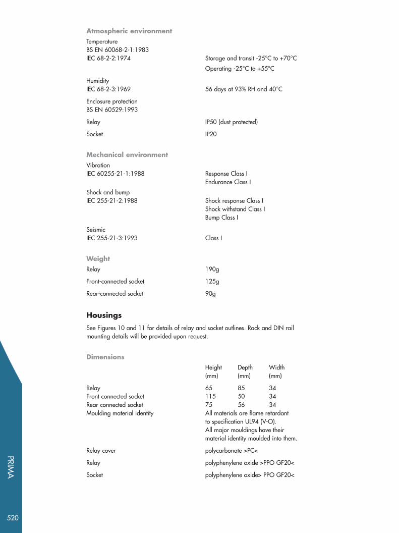
Atmospheric environmentTemperatureBS EN 60068-2-1:1983IEC 68-2-2:1974 Storage and transit -25°C to +70°C
Operating -25°C to +55°C
HumidityIEC 68-2-3:1969 56 days at 93% RH and 40°C
Enclosure protectionBS EN 60529:1993
Relay IP50 (dust protected)
Socket IP20
Mechanical environmentVibrationIEC 60255-21-1:1988 Response Class I
Endurance Class I
Shock and bumpIEC 255-21-2:1988 Shock response Class I
Shock withstand Class IBump Class I
SeismicIEC 255-21-3:1993 Class I
WeightRelay 190g
Front-connected socket 125g
Rear-connected socket 90g
Housings
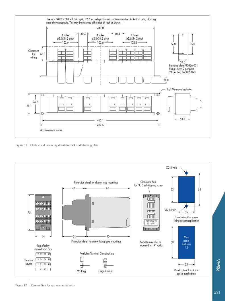
See Figures 10 and 11 for details of relay and socket outlines. Rack and DIN railmounting details will be provided upon request.
DimensionsHeight Depth Width(mm) (mm) (mm)
Relay 65 85 34Front connected socket 115 50 34Rear connected socket 75 56 34Moulding material identity All materials are flame retardant
to specification UL94 (V-O). All major mouldings have their material identity moulded into them.
Relay cover polycarbonate >PC<
Relay polyphenylene oxide >PPO GF20<
Socket polyphenylene oxide> PPO GF20<
PRIM
A
521
88.176.2
4 holes ø2.6x34.2 pitch
40.4
443.0
465.1482.6
34.0
85.0
Blanking plate PR0026 001Fixng screws 2 per plate24 per bag ZA0005 093
4 off M6 mounting holes
63.0
74.0
Clearancefor
wiring
The rack PR0025 001 will hold up to 12 Prima relays. Unused positions may be blanked off using blanking plate shown opposite. This may be mounted either side of rack as shown.
28.0
60.0
= =
All dimensions in mm
102.6
4 holes ø2.6x34.2 pitch
102.6
40.4 4 holes ø2.6x34.2 pitch
102.6
6453
35
35
69
Maxpanel
thickness1.2
Panel cut-out for screwfixing socket application
Panel cut-out for clip-onsocket application
12 22 32 42
14 24 34 44
A1 A2
11 21 31 41
Top of relayviewed from rear
TerminalLayout
Available Terminal Combinations
M3 Ring Cage Clamp
Ø2.8 Hole
Ø2.8 Hole
Clearance holefor No 6 self-tapping screw
Sockets may also bemounted in 19" racks
34
75
9447
9051Projection detail for screw fixing type mountings
Projection detail for clip-on type mountings
CUSTOMERSI.D. LABEL
Figure 11 Outline and mounting details for rack and blanking plate
Figure 12 Case outline for rear connected relay

PRIMA
522
Figure 13
Case outline
for front connected relay
44 34 24 14
42 32 22 12
A2 A1
41 31 21 11
Sockets may also be mountedon DIN rail to specifications
EN50054, DIN46277- 3 & BS5884
Top of relayviewed from front
TerminalLayout
35
7.5
55
110
131
5034
115
Clearance holefor No 6 self-tapping screw Ø4.40 Hole
Panel drilling details forscrew mounting of sockets
CUSTOMERSI.D. LABEL
Ø4.40 Hole
Ø2.8 Hole
Available Terminal Combinations
M3 Ring Cage Clamp
Relay Socket
Rack
Quantity
Quantity
Quantity
Contact Type (changeover)
Contacts
Flag
Timer
4 self-reset contacts
(3 contacts DDO timer)
3 hand/electrical-reset contacts
3 electrical-reset contacts
S
S
H
Standard contacts
Magnetic blow-out contacts
1
2
Following flag
Hand-reset flag (self-reset instantaneous only)
1
2
Delay on drop-off (self-reset dc only)
Delay on pick-up (self-reset dc only)
No delay (instantaneous)
D
P
N
T
B
Voltage
24/27
30/34
48/54
110/125
220/250
Electrical or Self-reset ac/dcHand/electrical reset dc
01
02
03
04
05
12
13
14
15
30/34
48/54
110/125
220/250
Test button fitted
No test button
Self test
Electrical orHand/electrical
reset acTerminal type
Cage clamp
M3 screw
1
3
Socket typeFront-connected
Rear-connected
F
R
Fixing screws
Quantity
Quantity
Quantity
Quantity
Quantity (bags)
(24 screws per bag)
E
PR
PR
PR P F 0 1
PS
PS
Blanking PlateP B 0 1
Rectifier
P A 0 1
P R 0 1
Quantity
Information required with order


Alstom Grid © - ALSTOM 2010. ALSTOM, the ALSTOM logo and any alternative version thereof are trademarks and service marks of ALSTOM. The other names mentioned, registered or not, are the property of their respective companies. The technical and other data contained in this document is provided for information only. Neither ALSTOM, its officers and employees accept responsibility for or should be taken as making any representation or warranty (whether express or implied) as to the accuracy or completeness of such data or the achievement of any projected performance criteria where these are indicated. ALSTOM reserves the right to revise or change this data at any time without further notice. Alstom Grid Worldwide Contact Centre www.grid.alstom.com/contactcentre/ Tel: +44 (0) 1785 250 070
www.alstom.com