Embed Size (px)
Citation preview

Rockwell Automation 1606-XLS480E-3 24V, 20A; Three Phase Input
1606-XLS480E-3 24V, 20A Three Phase Input POWER SUPPLY
Ultra-small size Extra-low inrush current Active power factor correction Wide range AC/DC input; auto select input Superior reserve power (can support 150% rated power for five seconds) Superior efficiency and temperature rating DC-OK and overload LED
1. GENERAL DESCRIPTION The most outstanding features of this 1606-XLS DIN-rail power supply are the high efficiency and the small size, which are achieved by a synchronous rectification and further novel design details. With short-term peak power capability of 150% and built-in large sized output capacitors, these features help start motors, charge capacitors and absorb reverse energy and often allow a unit of a lower wattage class to be used. High immunity to transients and power surges as well as low electromagnetic emission makes usage in nearly every environment possible. The integrated output power manager, a wide range input voltage design and virtually no input inrush current make installation and usage simple. Diagnostics are easy due to the dry DC-ok contact, a green DC-ok LED and red overload LED.
Unique quick-connect spring-clamp terminals allow a safe and fast installation and a large international approval package for a variety of applications makes this unit suitable for nearly every situation
2. SPECIFICATION QUICK REFERENCE
Output voltage DC 24V Adjustment range 24-28V Output current 20A Continuous, 24V 30A For typ. 4s, 24V Output power 480W Continuous, 24V 720W For typ. 4s, 24V Output ripple < 100mVpp 20Hz to 20MHz Input voltage AC 380-480V ±15% Line frequency 50-60Hz ±6% AC Input current 0.79 / 0.65A At 3x400 / 480VacPower factor 0.94 / 0.95 At 3x400 / 480VacAC Inrush current typ. 3A peak Efficiency 95.0 / 94.8% At 3x400 / 480VacLosses 25.3 / 26.4W At 3x400 / 480VacTemperature range -25°C to +70°C Operational Derating 12W/°C +60 to +70°C Hold-up time typ. 22 / 22ms At 3x400 / 480VacDimensions 65x124x127mm WxHxD
Output voltage DC 24V
Adjustment range 24-28V
3. AGENCY APPROVALS
IND. CONT. EQ. UL 508
UL 60950-1
Class I Div 2
EMC, LVD
4. RELATED PRODUCTS 1606-XLS-480E-3C Conformal coated
unit 1606-XLB Wall mount bracket
1606-XLSRED Redundancy Module
1606-XLBUFFER Buffer unit
10000051160 (Version 00)
www.ab.com Page 1

Rockwell Automation 1606-XLS480E-3 24V, 20A; Three Phase Input
10000051160 (Version 00)
www.ab.com Page 2
INDEX PAGE INDEX PAGE 1. General Description..............................................1 22. Fulfilled Standards ............................................. 15 2. Specification Quick reference ...............................1 23. Used Substances............................................... 15 3. Agency Approvals.................................................1 24. Physical Dimensions and Weight....................... 15 4. Related Products ..................................................1 25. Installation and Operation Instructions............... 16 5. AC-Input ...............................................................3 26. Accessories ....................................................... 17 6. DC-Input ...............................................................4 27. Application Notes............................................... 18 7. Input Inrush Current..............................................4 27.1. Repetitive Pulse Loading......................... 18 8. Output...................................................................4 27.2. Peak Current Capability........................... 19 9. Hold-up Time........................................................6 27.3. Back-feeding Loads................................. 19 10. DC-OK Relay Contact ..........................................8 27.4. Charging of Batteries............................... 19 11. Efficiency and Power Losses................................8 27.5. Output Circuit Breakers ........................... 20 12. Functional Diagram ..............................................9 27.6. External Input Protection ......................... 21 13. Product Face Label ............................................10 27.7. 2-Phase Operation .................................. 21 14. Terminals and Wiring..........................................11 27.8. Parallel Use to Increase Output Power.... 22 15. Reliability ............................................................11 27.9. Parallel Use for Redundancy ................... 22 16. EMC ...................................................................12 27.10. Daisy Chaining of Outputs ....................... 22 17. Environment .......................................................13 27.11. Series Operation...................................... 23 18. Protection Features ............................................14 27.12. Inductive and Capacitive Loads............... 23 19. Safety .................................................................14 27.13. Use in a Tightly Sealed Enclosure........... 23 20. Dielectric Strength ..............................................14 27.14. Mounting Orientations ............................. 24 21. Approvals............................................................15
INTENDED USE Those responsible for the application and use of the products must satisfy themselves that all necessary steps have been taken to assure that each application and use meets all performance and safety requirements, including and applicable laws, regulation , codes, and standards.
TERMINOLOGY AND ABBREVIATIONS PE and symbol PE is the abbreviation for Protective Earth and has the same meaning as the symbol . Earth, Ground This document uses the term “earth” which is the same as the U.S. term “ground”. T.b.d. To be defined, value or description will follow later. AC 400V A figure displayed with the AC or DC before the value represents a nominal voltage with standard
tolerances (usually ±15%) included. E.g.: DC 12V describes a 12V battery disregarding whether it is full (13.7V) or flat (10V) As long as not otherwise stated, AC 380V and AC 400V parameters are valid at 50Hz and AC 480V parameters are valid at 60Hz mains frequency.
400Vac A figure with the unit (Vac) at the end is a value without any additional tolerances included. PELV Protective Extra Low Voltage SELV Safety Extra Low Voltage
DISCLAIMER The information presented in this document is believed to be accurate and reliable and may change without notice.

Rockwell Automation 1606- XLS480E-3 24V, 20A; Three Phase Input
5. AC-INPUT
AC input nom. 3AC 380-480V Wide-range input,, see Fig. 5-1 Consult factory if one phase is earthed.
AC input range min. 3x 323-552Vac Continuous operation min. 3x 280-323Vac Full power for 200ms, no damage between 0 and 280Vac For 2-phase operation see section 27.7
Input frequency nom. 50–60Hz ±6% Turn-on voltage typ. 3x 263Vac Steady-state value, see Fig. 5-1
Shut-down voltage typ. 3x 242Vac Steady-state value, see Fig. 5-1
3AC 400V 3AC 480V
Input current typ. 0.79A 0.65A At 24V, 20A, all three phases equal voltage See Fig. 5-3
Power factor * typ. 0.94 0.95 At 24V, 20A, see Fig. 5-4
Start-up delay typ. 350ms 290ms See Fig. 5-2
Rise time typ. 30ms 30ms 0mF, 24V, 20A, see Fig. 5-2
typ. 40ms 40ms 20mF, 24V, 20A, see Fig. 5-2
Turn-on overshoot max. 500mV 500mV See Fig. 5-2
* The power factor is the ratio of the true (or real) power to the apparent power in an AC circuit. Fig. 5-1 Input voltage range Fig. 5-2 Turn-on behavior, definitions
Turn
-on
323V
Rated input range
VIN
POUT
280V 3x 552Vac
full powerfor 200ms
Shut
-dow
n
Start-updelay
RiseTime O
vers
hoot
- 5%OutputVoltage
IntputVoltage
Fig. 5-3 Input current vs. output load at 24V Fig. 5-4 Power factor vs. output load
20A2 4 6 8 10 12 14 16 180
0.10.20.30.40.50.6
0.8AInput Current, typ.
0.7
Output Current
3x 400Vac
3x 480Vac
Power Factor, typ.
2 4 6 8 10 12 14 16 18 20A0.75
0.8
0.85
0.9
0.95
1.0
3x400Vac
3x480Vac
Output Current
10000051160 (Version 00) www.ab.com
Page 3
Rockwell Automation 1606- XLS480E-3 24V, 20A; Three Phase Input 6. DC-INPUT The 1606-XLS480E-3 shall not be used with a DC-input voltage without consulting Rockwell Automation. Check 1606-XLS480E-3 for DC-input voltage. (special version for intermediate bus systems, drive systems)
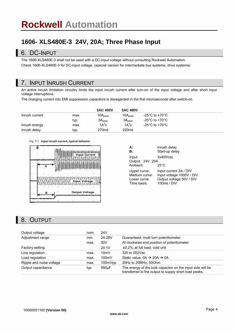
7. INPUT INRUSH CURRENT An active inrush limitation circuitry limits the input inrush current after turn-on of the input voltage and after short input voltage interruptions. The charging current into EMI suppression capacitors is disregarded in the first microseconds after switch-on. 3AC 400V 3AC 480V
Inrush current max. 10Apeak 10Apeak -25°C to +70°C typ. 3Apeak 3Apeak -25°C to +70°C Inrush energy max. 1A2s 1A2s -25°C to +70°C Inrush delay typ. 270ms 220ms
Fig. 7-1 Input inrush current, typical behavior
Input Current
Input Voltage
Output Voltage
A
B
A: Inrush delay B: Start-up delay Input: 3x400Vac Output: 24V, 20A Ambient: 25°C Upper curve: Input current 2A / DIV Medium curve: Input voltage 1000V / DIV Lower curve: Output voltage 50V / DIV Time basis: 100ms / DIV
8. OUTPUT
Output voltage nom. 24V Adjustment range min. 24-28V Guaranteed, multi turn potentiometer max. 30V At clockwise end position of potentiometer Factory setting 24.1V ±0.2%, at full load, cold unit Line regulation max. 10mV 320 to 552Vac Load regulation max. 100mV Static value, 0A 20A 0A Ripple and noise voltage max. 100mVpp 20Hz to 20MHz, 50Ohm
Output capacitance typ. 950µF The energy of the bulk capacitor on the input side will be transferred to the output to supply short load peaks.
10000051160 (Version 00) www.ab.com
Page 4
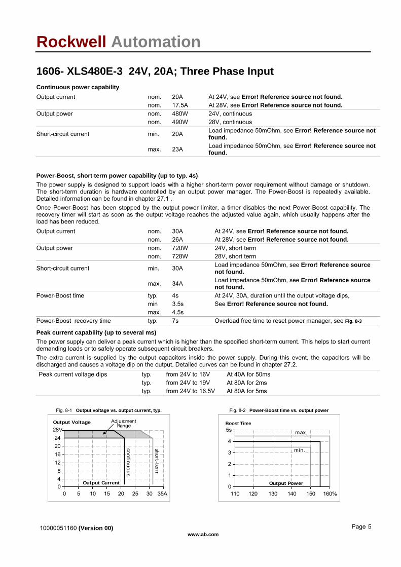
Rockwell Automation 1606- XLS480E-3 24V, 20A; Three Phase Input Continuous power capability
Output current nom. 20A At 24V, see Error! Reference source not found. nom. 17.5A At 28V, see Error! Reference source not found. Output power nom. 480W 24V, continuous nom. 490W 28V, continuous
Short-circuit current min. 20A Load impedance 50mOhm, see Error! Reference source not found.
max. 23A Load impedance 50mOhm, see Error! Reference source not found.
Power-Boost, short term power capability (up to typ. 4s) The power supply is designed to support loads with a higher short-term power requirement without damage or shutdown. The short-term duration is hardware controlled by an output power manager. The Power-Boost is repeatedly available. Detailed information can be found in chapter 27.1 . Once Power-Boost has been stopped by the output power limiter, a timer disables the next Power-Boost capability. The recovery timer will start as soon as the output voltage reaches the adjusted value again, which usually happens after the load has been reduced.
Output current nom. 30A At 24V, see Error! Reference source not found. nom. 26A At 28V, see Error! Reference source not found. Output power nom. 720W 24V, short term nom. 728W 28V, short term
Short-circuit current min. 30A Load impedance 50mOhm, see Error! Reference source not found.
max. 34A Load impedance 50mOhm, see Error! Reference source not found.
Power-Boost time typ. 4s At 24V, 30A, duration until the output voltage dips, min 3.5s See Error! Reference source not found. max. 4.5s Power-Boost recovery time typ. 7s Overload free time to reset power manager, see Fig. 8-3
Peak current capability (up to several ms) The power supply can deliver a peak current which is higher than the specified short-term current. This helps to start current demanding loads or to safely operate subsequent circuit breakers. The extra current is supplied by the output capacitors inside the power supply. During this event, the capacitors will be discharged and causes a voltage dip on the output. Detailed curves can be found in chapter 27.2.
Peak current voltage dips typ. from 24V to 16V At 40A for 50ms typ. from 24V to 19V At 80A for 2ms typ. from 24V to 16.5V At 80A for 5ms
Fig. 8-1 Output voltage vs. output current, typ. Fig. 8-2 Power-Boost time vs. output power
Output Voltage
00 5 10 20 25
48
12
28V
162024
35A15 30
Output Current
sho rt-t erm
AdjustmentRange
continuous
max.
Bonus Time
0110 120 130 140 150 160%
Output Power1
2
3
4
5s
min.
Boost Time
10000051160 (Version 00) www.ab.com
Page 5
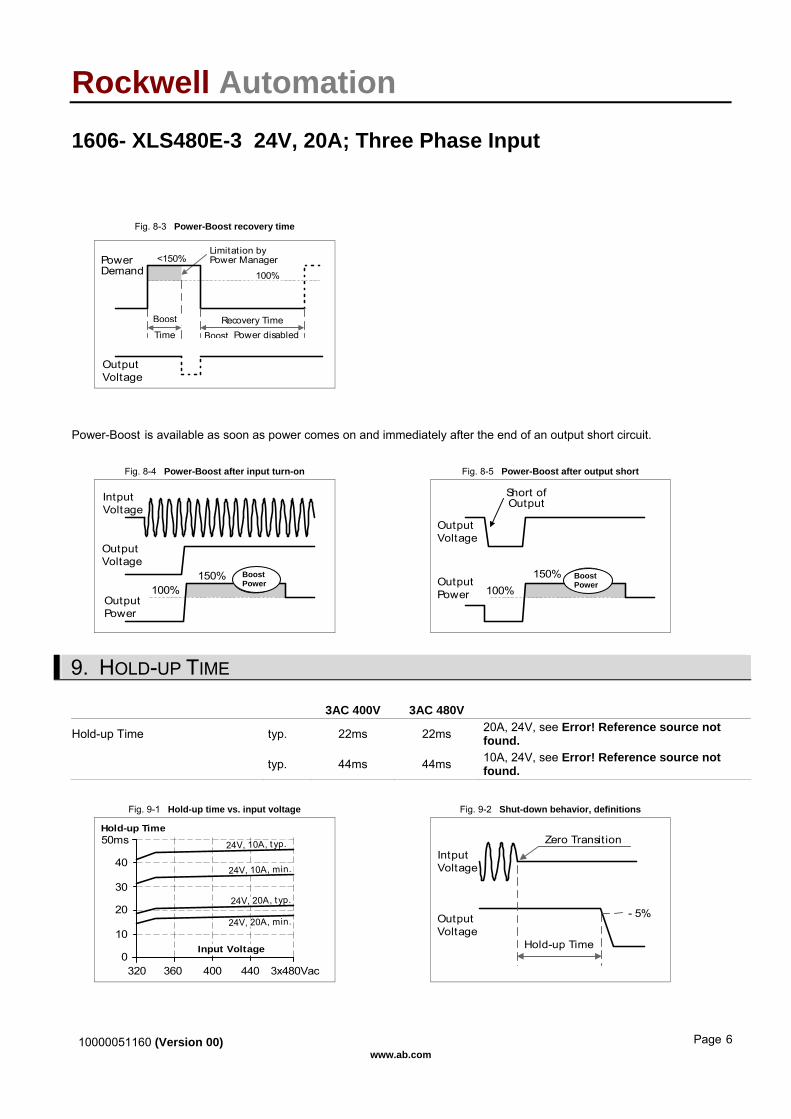
Rockwell Automation 1606- XLS480E-3 24V, 20A; Three Phase Input Fig. 8-3 Power-Boost recovery time
PowerDemand
OutputVoltage
Limitation byPower Manager
Bonus Power disabledRecovery Time
100%
<150%
BonusTime
Boost
Boost
Power-Boost is available as soon as power comes on and immediately after the end of an output short circuit. Fig. 8-4 Power-Boost after input turn-on Fig. 8-5 Power-Boost after output short
100%
OutputVoltage
IntputVoltage
BonusPower
OutputPower
150%
Short ofOutput
100%
OutputVoltage
BonusPowerOutput
Power
150%
Boost Power
Boost Power
9. HOLD-UP TIME
3AC 400V 3AC 480V
Hold-up Time typ. 22ms 22ms 20A, 24V, see Error! Reference source not found.
typ. 44ms 44ms 10A, 24V, see Error! Reference source not found.
Fig. 9-1 Hold-up time vs. input voltage Fig. 9-2 Shut-down behavior, definitions
0
10
20
30
40
50ms
320 360 400 440 3x480Vac
Input Voltage
Hold-up Time
24V, 10A, t yp.
24V, 20A, typ.
24V, 10A, min.
24V, 20A, min.
- 5%
Hold-up Time
Zero Transition
OutputVoltage
IntputVoltage
10000051160 (Version 00) www.ab.com
Page 6

Rockwell Automation 1606- XLS480E-3 24V, 20A; Three Phase Input
10000051160 (Version 00) www.ab.com
Page 7

Rockwell Automation 1606- XLS480E-3 24V, 20A; Three Phase Input
10. DC-OK RELAY CONTACT This feature monitors the output voltage, which is produced by the power supply itself. It is independent of a back-fed voltage from a unit which is connected in parallel to the power supply output.
Contact closes As soon as the output voltage reaches the adjusted output voltage.
Contact opens As soon as the output voltage dips more than 10% below the adjusted output voltage. Short dips will be extended to a signal length of 250ms. Dips shorter than 1ms will be ignored.
Contact re-closes As soon as the output voltage exceeds 90% of the adjusted voltage. Contact ratings max 60Vdc 0.3A, 30Vdc 1A, 30Vac 0.5A resistive load min 1mA at 5Vdc min. permissible load
Isolation voltage See dielectric strength table in section Error! Reference source not found.
Fig. 10-1 DC-ok relay contact behavior
250ms
90%VADJ
<1ms
10%
open
VOUT= VADJ
openclosed closed
>1ms
Note: The DC-ok feature requires that the output voltage reaches the nominal (=adjusted) level after turn-on in order to function according to specification. If this level cannot be achieved, the overload lamp will be on and the DC-ok contact will be open. The overload signal will only shut off as soon as the adjusted voltage is reached. This is an important condition to consider particularly, if the load is a battery, the power supply is used in parallel or the power supply is used for N+1 redundant systems.
11. EFFICIENCY AND POWER LOSSES
3AC 400V 3AC 480V Efficiency typ. 95.0% 94.8% 20A, 24V Power losses typ. 25.3W 26.3W 20A, 24V typ. 8.2W 10.0W 0A
Fig. 11-1 Efficiency vs. output current at 24V Fig. 11-2 Losses vs. output current at 24V
Efficiency
4 6 8 10 12 14 16 18 20A888990919293
Output Current
9495
96%
3x400Vac
3x480Vac
Power Losses
0 2 4 6 8 10 12 14 20A0
5
10
15
20
Output Current
25
30W
16 18
3x400Vac
3x480Vac
10000051160 (Version 00) www.ab.com
Page 8
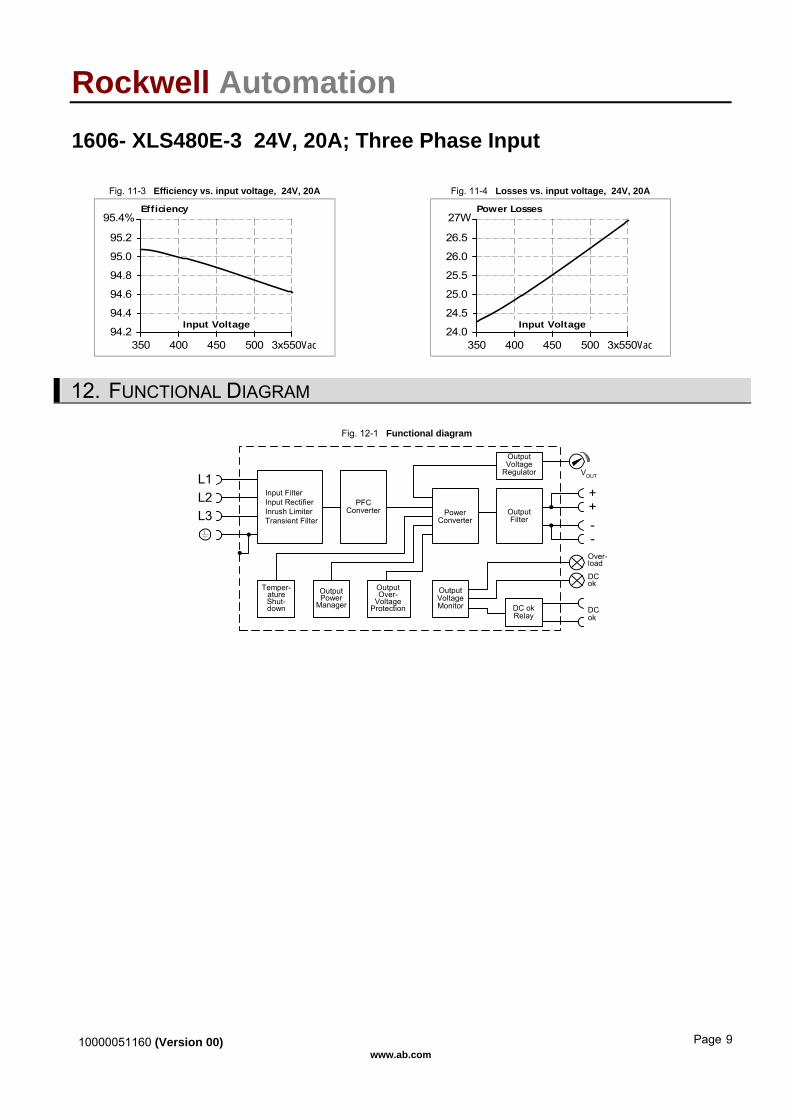
Rockwell Automation 1606- XLS480E-3 24V, 20A; Three Phase Input Fig. 11-3 Efficiency vs. input voltage, 24V, 20A Fig. 11-4 Losses vs. input voltage, 24V, 20A
Efficiency
350 400 450 500 3x550Vac94.2
94.4
94.6
94.8
Input Voltage
95.0
95.2
95.4%
Power Losses
350 400 450 500 3x550Vac24.0
24.5
25.0
25.5
Input Voltage
26.0
26.5
27W
12. FUNCTIONAL DIAGRAM Fig. 12-1 Functional diagram
++
--
VOUT
DCok
OutputOver-
VoltageProtection
PFCConverter
Input FilterInput RectifierInrush LimiterTransient Filter
OutputVoltage
Regulator
PowerConverter
OutputFilter
DC okRelay
OutputVoltageMonitor
OutputPower
Manager
Temper-atureShut-down
Over-load
DCok
L2L3
L1
10000051160 (Version 00) www.ab.com
Page 9
Rockwell Automation 1606- XLS480E-3 24V, 20A; Three Phase Input
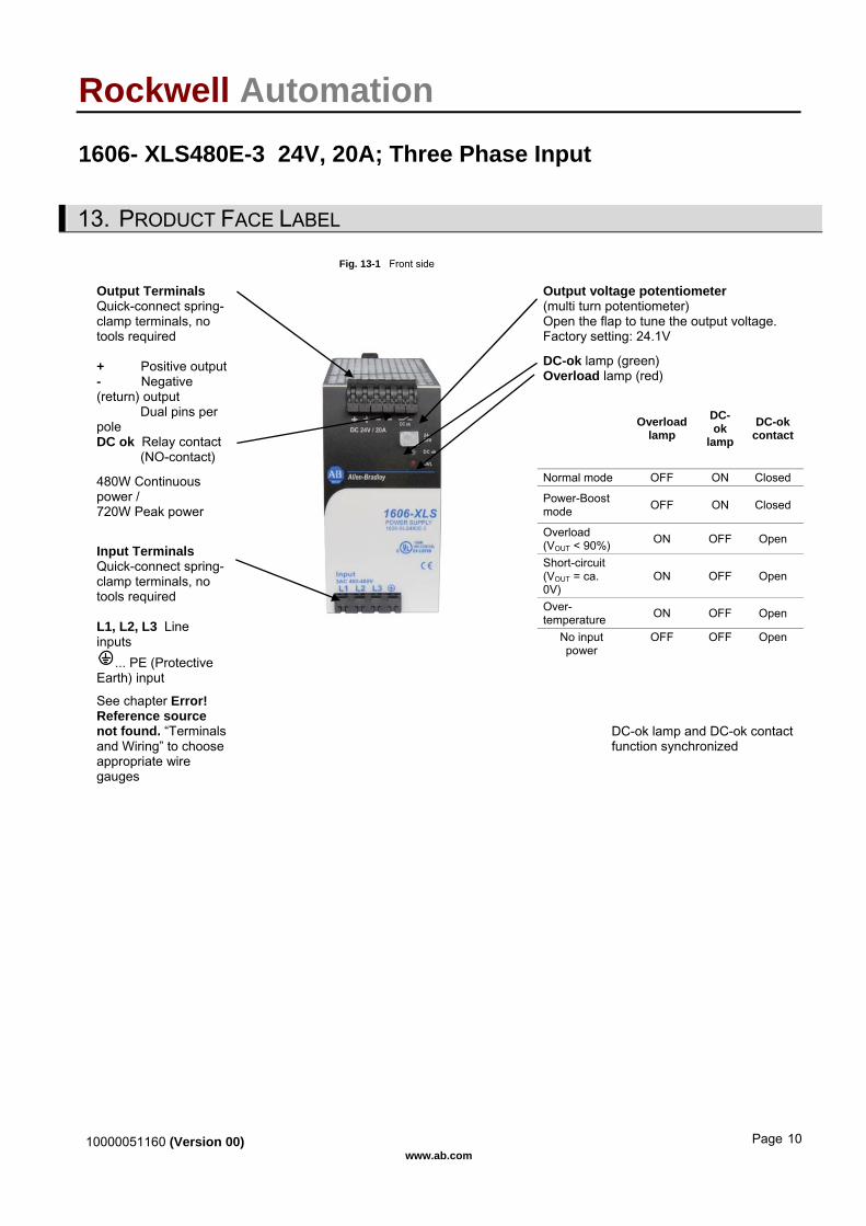
13. PRODUCT FACE LABEL
Fig. 13-1 Front side
Output voltage potentiometer (multi turn potentiometer) Open the flap to tune the output voltage. Factory setting: 24.1V
DC-ok lamp (green) Overload lamp (red)
Output Terminals Quick-connect spring-clamp terminals, no tools required + Positive output - Negative (return) output Dual pins per pole DC ok Relay contact (NO-contact)
Overload lamp
DC-ok
lamp DC-ok
contact
Normal mode OFF ON Closed 480W Continuous power / 720W Peak power
Power-Boost mode OFF ON Closed
Overload (VOUT < 90%) ON OFF Open
Short-circuit (VOUT = ca. 0V)
ON OFF Open
Over- temperature ON OFF Open
Input Terminals Quick-connect spring-clamp terminals, no tools required L1, L2, L3 Line inputs
... PE (Protective Earth) input
No input power
OFF OFF Open
See chapter Error! Reference source not found. “Terminals and Wiring” to choose appropriate wire gauges
DC-ok lamp and DC-ok contact function synchronized
10000051160 (Version 00) www.ab.com
Page 10

Rockwell Automation 1606- XLS480E-3 24V, 20A; Three Phase Input
14. TERMINALS AND WIRING
Type Bi-stable, quick-connect spring clamp terminals. IP20 Finger safe construction. Suitable for field- and factory installation. Shipped in open position.
Solid wire 0.5-6mm2 Stranded wire 0.5-4mm2 American wire gauge 20-10 AWG Ferrules Allowed, but not required Wire stripping length 10mm / 0.4inch Pull-out force 10AWG:80N, 12AWG:60N, 14AWG:50N, 16AWG:40N (according to UL486E)
Fig. 14-1 Connecting a wire
1. Insert the wire 2. Snap the leverTo disconnect wire: same procedurevice versa
Instructions: a) Use appropriate copper cables that are designed
for an operating temperature of: 60°C for ambient up to 45°C and 75°C for ambient up to 60°C minimum.
b) Follow national installation codes and installation regulations!
c) Ensure that all strands of a stranded wire enter the terminal connection!
d) Up to two stranded wires with the same cross section are permitted in one connection point (except PE wire).
e) Do not use the unit without PE connection.
15. RELIABILITY
3AC 400V 3AC 480V Lifetime expectancy min. 51 000h 48 000h 40°C, 24V, 20A min. 89 000h 86 000h 40°C, 24V, 10A min. 144 000h 135 000h 25°C, 24V, 20A MTBF SN 29500, IEC 61709 690 000h 670 000h 40°C, 24V, 20A 1 194 000h 1 159 000h 25°C, 24V, 20A MTBF MIL HDBK 217F 284 000h 271 000h 40°C, 24V, 20A, Ground Benign GB40 389 000h 371 000h 25°C, 24V, 20A, Ground Benign GB25
The Lifetime expectancy shown in the table indicates the operating hours (service life) and is determined by the lifetime expectancy of the built-in electrolytic capacitors. Lifetime expectancy is specified in operational hours. Lifetime expectancy is calculated according to the capacitor’s manufacturer specification. The prediction model allows a calculation of up to 15 years from date of shipment. MTBF stands for Mean Time Between Failure, which is calculated according to statistical device failures, and indicates reliability of a device. It is the statistical representation of the likelihood of a unit to fail and does not necessarily represent the life of a product.
10000051160 (Version 00) www.ab.com
Page 11

Rockwell Automation 1606- XLS480E-3 24V, 20A; Three Phase Input 16. EMC The power supply is suitable for applications in industrial environment as well as in residential, commercial and light industry environment without any restrictions. CE mark is in conformance with EMC guideline 89/336/EEC and 93/68/EEC and the low-voltage directive (LVD) 73/23/EWG.
EMC Immunity EN 61000-6-1 EN 61000-6-2 Generic standards
Electrostatic discharge EN 61000-4-2 Contact discharge Air discharge
8kV 15kV
Criterion A Criterion A
Electromagnetic RF field EN 61000-4-3 80MHz-1GHz 10V/m Criterion A
Fast transients (Burst) EN 61000-4-4 Input lines Output lines
4kV 2kV
Criterion A Criterion A
Surge voltage on input EN 61000-4-5 L1 L2, L2 L3, L1 L3
2kV Criterion A
Surge voltage on input EN 61000-4-5 L1 / L2 / L3 PE 4kV Criterion A
Surge voltage on output EN 61000-4-5 + - + / - PE
500V 500V
Criterion A Criterion A
Conducted disturbance EN 61000-4-6 0.15-80MHz 10V Criterion A
Mains voltage dips Dip on all three phases
EN 61000-4-11 70% of 380Vac 40% of 380Vac 40% of 380Vac
266Vac, 10ms 152Vac, 100ms 152Vac, 1000ms
Criterion A Criterion C Criterion C
Mains voltage dips Dip on one phase
EN 61000-4-11 70% of 380Vac 40% of 380Vac 40% of 380Vac
266Vac, 10ms 152Vac, 100ms 152Vac, 1000ms
Criterion A Criterion A Criterion A
Voltage interruptions EN 61000-4-11 0Vac, 5000ms Criterion C
Voltage sags SEMI F47 0200 Dips on two phases
according to section 7.2. (SEMI F47-200)
304Vac, 1000ms 266Vac, 500ms 190Vac, 200ms
Criterion A Criterion A Criterion A
Powerful transients VDE 0160 over entire load range 1300V, 1.3ms Criterion A Criterions: A: Power supply shows normal operation behavior within the defined limits. C: Temporary loss of function is possible. Power supply might shut-down and restarts by itself. No damages or hazards for the power supply occur.
EMC Emission EN 61000-6-3 and EN 61000-6-4 Generic standards
Conducted emission EN 55011, EN 55022, FCC Part 15, CISPR 11, CISPR 22 Class B, input lines
Radiated emission EN 55011, EN 55022 Class B Harmonic input current EN 61000-3-2 Fulfilled, active PFC Voltage fluctuations, flicker EN 61000-3-3 Fulfilled
This device complies with FCC Part 15 rules. Operation is subjected to following two conditions: (1) this device may not cause harmful interference, and (2) this device must accept any interference received, including interference that may cause undesired operation.
Switching Frequencies The power supply has three converters with three different switching frequencies included. One is nearly constant. The other two are input voltage and load dependent.
Switching frequency 1 100kHz Nearly constant Switching frequency 2 30kHz to 90kHz Input voltage and load dependent Switching frequency 3 40kHz to 220kHz Input voltage and load dependent
10000051160 (Version 00) www.ab.com
Page 12

Rockwell Automation 1606- XLS480E-3 24V, 20A; Three Phase Input
17. ENVIRONMENT
Operational temperature -25°C to +70°C (-13°F to 158°F) Reduce output power above +60°C
Output de-rating 12W/°C 60-70°C (140°F to 158°F), see Error! Reference source not found.
Storage temperature -40 to +85°C (-40°F to 185°F) Storage and transportation
Humidity 5 to 95% r.H. IEC 60068-2-30 Do not energize while condensation is present
Vibration sinusoidal 2-17.8Hz: ±1.6mm;
17.8-500Hz: 2g 2 hours / axis
IEC 60068-2-6
Vibration random 0.5m2(s3) 2 hours / axis
IEC 60068-2-64
Shock 30g 6ms, 20g 11ms
3 bumps / direction, 18 bumps in total
IEC 60068-2-27
Altitude 0 to 6000m (0 to 20 000ft) Reduce output power or ambient temperature above 2000m sea level.
Output de-rating (for altitude) 30W/1000m or 5°C/1000m above 2000m, see Error! Reference source not found.
Over-voltage category III EN 50178, altitudes up to 2000m II Altitudes from 2000m to 6000m Degree of pollution 2 EN 50178, not conductive
Fig. 17-1 Output current vs. ambient temp., Fig. 17-2 Output current vs. altitude
Allowed Output Current at 24V
0-25 0 20 70°C
5
10
15
20
25
30A
cont inuous
Ambient Temperature
for typ. 4s
40 60
A... 2x 460 to 552VacB... 2x 340 to 460Vac
B A
Allowed OutputCurrent at 24V
00 2000 4000 6000m
5
10
15
20
25
30A
cont inuous
Altitude
for typ. 4s
A... Tamb < 60°CB... Tamb < 50°CC... Tamb < 40°C
AB
C
The ambient temperature is defined as the air temperature 2cm below the unit.
10000051160 (Version 00) www.ab.com
Page 13
Rockwell Automation 1606- XLS480E-3 24V, 20A; Three Phase Input
18. PROTECTION FEATURES
Output protection Electronically protected against overload, no-load and short-circuits Output over-voltage protection typ. 32Vdc
max. 35Vdc In case of an internal power supply defect, a redundant circuitry limits the maximum output voltage. The output shuts-down and automatically attempts to restart.
Degree of protection IP 20 EN/IEC 60529 Penetration protection > 3.5mm e.g. screws, small parts Over-temperature protection yes Output shut-down with automatic restart Input transient protection MOV (Metal Oxide Varistor) and active transient filter Internal input fuse Not included See section 27.6
Note: In case of a protection event, audible noise may occur.
19. SAFETY
Input / output separation SELV IEC/EN 60950-1 PELV EN 60204-1, EN 50178, IEC 60364-4-41 double or reinforced insulation Class of protection I PE (Protective Earth) connection required Isolation resistance > 5MOhm Input to output, 500Vdc PE resistance < 0.1Ohm Between housing and PE terminal Touch current (leakage current) typ. 0.38mA 3x 440Vac, 50Hz, TN mains typ. 0.54mA 3x 528Vac, 60Hz, TN mains < 0.47mA 3x 400Vac, 50Hz, TN mains < 0.7mA 3x 480Vac, 60Hz, TN mains
20. DIELECTRIC STRENGTH
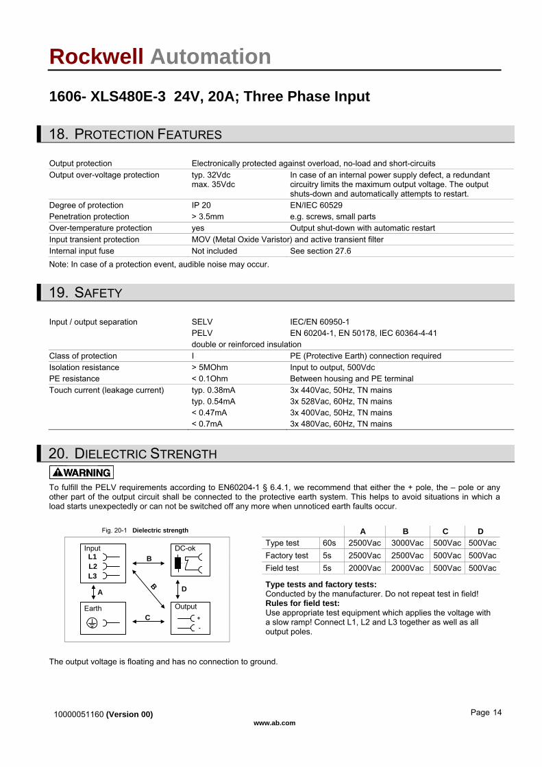
To fulfill the PELV requirements according to EN60204-1 § 6.4.1, we recommend that either the + pole, the – pole or any other part of the output circuit shall be connected to the protective earth system. This helps to avoid situations in which a load starts unexpectedly or can not be switched off any more when unnoticed earth faults occur. Fig. 20-1 Dielectric strength A B C D
Type test 60s 2500Vac 3000Vac 500Vac 500VacFactory test 5s 2500Vac 2500Vac 500Vac 500VacField test 5s 2000Vac 2000Vac 500Vac 500Vac
A D
C
B
BL1Input DC-ok
Earth Output
-
+
L3L2
Type tests and factory tests: Conducted by the manufacturer. Do not repeat test in field! Rules for field test: Use appropriate test equipment which applies the voltage with a slow ramp! Connect L1, L2 and L3 together as well as all output poles.
The output voltage is floating and has no connection to ground.
10000051160 (Version 00) www.ab.com
Page 14

Rockwell Automation 1606- XLS480E-3 24V, 20A; Three Phase Input 21. APPROVALS
IEC 60950-1 IECEE
CB SCHEME
CB Scheme, Information Technology Equipment
UL 508 IND. CONT. EQ.
LISTED E198865 listed for use in U.S.A. (UL 508) and Canada (C22.2 No. 14-95) Industrial Control Equipment
UL 60950-1
RECOGNIZED E137006 recognized for the use in U.S.A. (UL 60950-1) and Canada (C22.2 No. 60950) Information Technology Equipment, Level 5
UL 1604
RECOGNIZED E246877 recognized for use in U.S.A. (UL 1604) and Canada (C22.2 No. 213-M1987) Hazardous Location Class I Div 2 T4A Groups A,B,C,D and Class I Zone 2 Groups IIA, IIB and IIC
The unit is suitable for use in Class I Division 2 Groups A, B, C, D locations as well as for Class I Zone 2 Groups IIA, IIB and IIC locations. Substitution of components may impair suitability for Class I Division 2 environment. Do not disconnect equipment unless power has been switched off. Wiring must be in accordance with Class I, Division 2 wiring methods of the National Electrical Code, NFPA 70, and in accordance with other local or national codes.
SEMI F47
SEMI F47-0200 Power Quality Star Ride-through compliance for semiconductor industry. Full SEMI range compliance (Dips on two phase: 304Vac for 1000ms, 266Vac for 500ms and 190Vac for 200ms)
22. FULFILLED STANDARDS
EN 61558-2-17 Safety of Power Transformers EN/IEC 60204-1 Safety of Electrical Equipment of Machines EN/IEC 61131-2 Programmable Controllers EN 50178 Electronic Equipment in Power Installations
23. USED SUBSTANCES
The unit does not release any silicone and is suitable for the use in paint shops. Electrolytic capacitors included in this unit do not use electrolytes such as Quaternary Ammonium Salt Systems. Plastic housings and other molded plastic materials are free of halogens, wires and cables are not PVC insulated.
The production material within our production does not include following toxic chemicals: Polychlorized Biphenyl (PCB), Polychlorized Terphenyl (PCT), Pentachlorophenol (PCP), Polychlorinated naphthalene (PCN), Polybrom Biphenyll (PBB), Polybrom Bipheny-oxyd (PBO), Polybrominated Diphenylether (PBDE), Polychlorinated Diphenylether (PCDE), Polydibromphenyl Oxyd (PBDO), Cadmium, Asbest, Mercury, Silicia
24. PHYSICAL DIMENSIONS AND WEIGHT Weight 870g / 1.92lb DIN-Rail Use 35mm DIN-rails according to EN 60715 or EN 50022 with a height of 7.5 or 15mm.
The DIN-rail height must be added to the depth (127mm) to calculate the total required installation depth.
10000051160 (Version 00) www.ab.com
Page 15
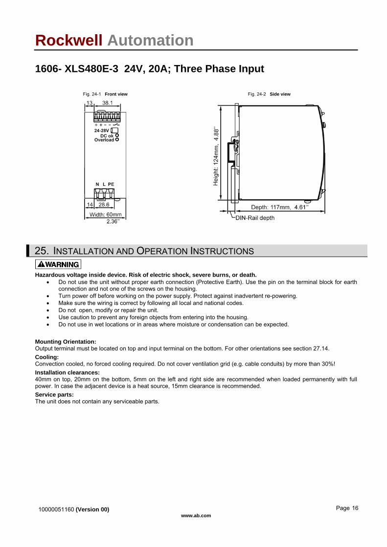
Rockwell Automation 1606- XLS480E-3 24V, 20A; Three Phase Input Fig. 24-1 Front view Fig. 24-2 Side view
25. INSTALLATION AND OPERATION INSTRUCTIONS
Hazardous voltage inside device. Risk of electric shock, severe burns, or death. • Do not use the unit without proper earth connection (Protective Earth). Use the pin on the terminal block for earth
connection and not one of the screws on the housing. • Turn power off before working on the power supply. Protect against inadvertent re-powering. • Make sure the wiring is correct by following all local and national codes. • Do not open, modify or repair the unit. • Use caution to prevent any foreign objects from entering into the housing. • Do not use in wet locations or in areas where moisture or condensation can be expected.
Mounting Orientation: Output terminal must be located on top and input terminal on the bottom. For other orientations see section 27.14. Cooling: Convection cooled, no forced cooling required. Do not cover ventilation grid (e.g. cable conduits) by more than 30%! Installation clearances: 40mm on top, 20mm on the bottom, 5mm on the left and right side are recommended when loaded permanently with full power. In case the adjacent device is a heat source, 15mm clearance is recommended. Service parts: The unit does not contain any serviceable parts.
10000051160 (Version 00) www.ab.com
Page 16
Rockwell Automation 1606- XLS480E-3 24V, 20A; Three Phase Input
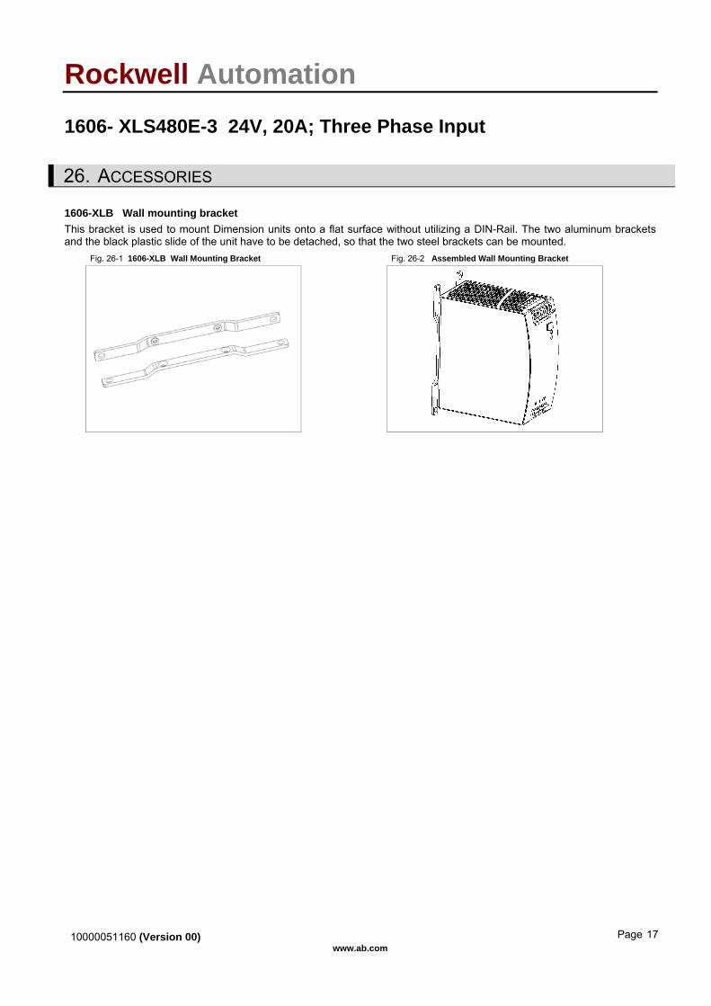
26. ACCESSORIES 1606-XLB Wall mounting bracket This bracket is used to mount Dimension units onto a flat surface without utilizing a DIN-Rail. The two aluminum brackets and the black plastic slide of the unit have to be detached, so that the two steel brackets can be mounted.
Fig. 26-1 1606-XLB Wall Mounting Bracket Fig. 26-2 Assembled Wall Mounting Bracket
10000051160 (Version 00) www.ab.com
Page 17
Rockwell Automation 1606- XLS480E-3 24V, 20A; Three Phase Input 27. APPLICATION NOTES
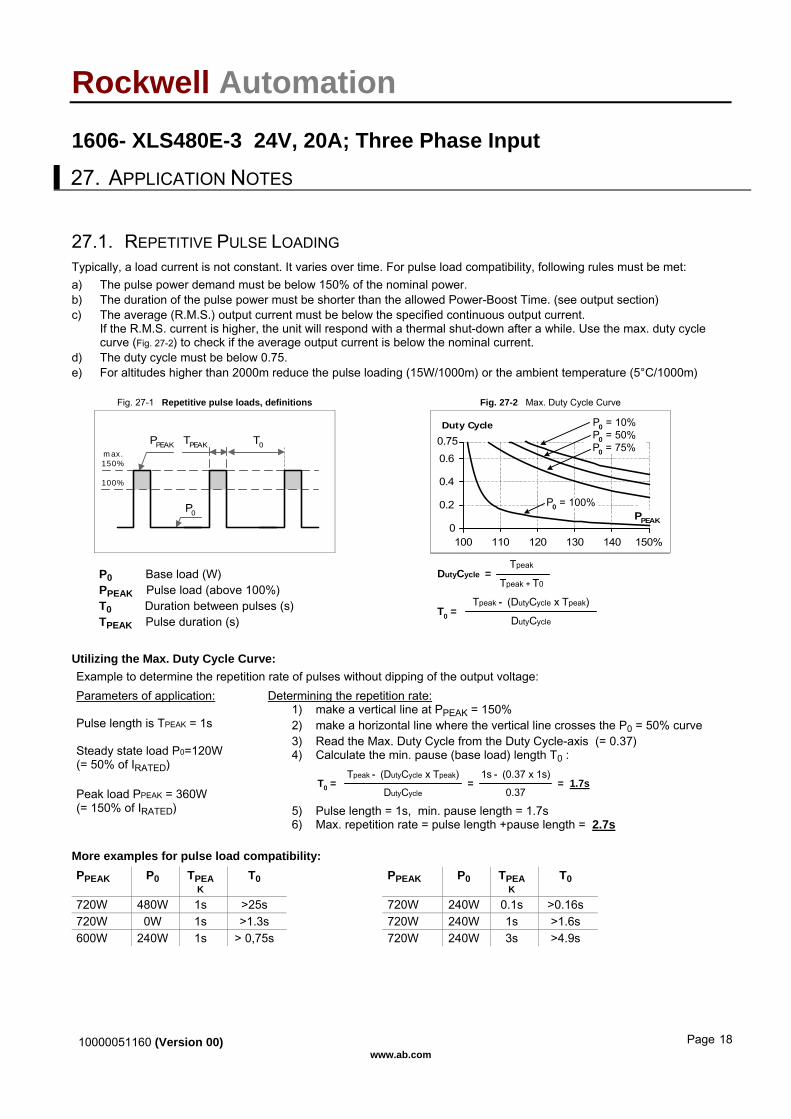
27.1. REPETITIVE PULSE LOADING Typically, a load current is not constant. It varies over time. For pulse load compatibility, following rules must be met: a) The pulse power demand must be below 150% of the nominal power. b) The duration of the pulse power must be shorter than the allowed Power-Boost Time. (see output section) c) The average (R.M.S.) output current must be below the specified continuous output current.
If the R.M.S. current is higher, the unit will respond with a thermal shut-down after a while. Use the max. duty cycle curve (Fig. 27-2) to check if the average output current is below the nominal current.
d) The duty cycle must be below 0.75. e) For altitudes higher than 2000m reduce the pulse loading (15W/1000m) or the ambient temperature (5°C/1000m)
Fig. 27-1 Repetitive pulse loads, definitions Fig. 27-2 Max. Duty Cycle Curve
100%
PPEAK TPEAK
P0
T0max.150%
150%1000
0.2
0.4
0.60.75Duty Cycle
110 120 130 140
PPEAK
P0 = 10%P0 = 50%P0 = 75%
P0 = 100%
P0 Base load (W) PPEAK Pulse load (above 100%) T0 Duration between pulses (s) TPEAK Pulse duration (s)
DutyCycleT0 =
Tpeak - (DutyCycle x Tpeak)
Tpeak + T0
TpeakDutyCycle =
Utilizing the Max. Duty Cycle Curve: Example to determine the repetition rate of pulses without dipping of the output voltage: Parameters of application: Pulse length is TPEAK = 1s Steady state load P0=120W (= 50% of IRATED) Peak load PPEAK = 360W (= 150% of IRATED)
Determining the repetition rate: 1) make a vertical line at PPEAK = 150% 2) make a horizontal line where the vertical line crosses the P0 = 50% curve 3) Read the Max. Duty Cycle from the Duty Cycle-axis (= 0.37) 4) Calculate the min. pause (base load) length T0 :
DutyCycleT0 =
Tpeak - (DutyCycle x Tpeak)=
0.37
1s - (0.37 x 1s)= 1.7s
5) Pulse length = 1s, min. pause length = 1.7s 6) Max. repetition rate = pulse length +pause length = 2.7s
More examples for pulse load compatibility: PPEAK P0 TPEA
K T0 PPEAK P0 TPEA
K T0
720W 480W 1s >25s 720W 240W 0.1s >0.16s 720W 0W 1s >1.3s 720W 240W 1s >1.6s 600W 240W 1s > 0,75s 720W 240W 3s >4.9s
10000051160 (Version 00) www.ab.com
Page 18
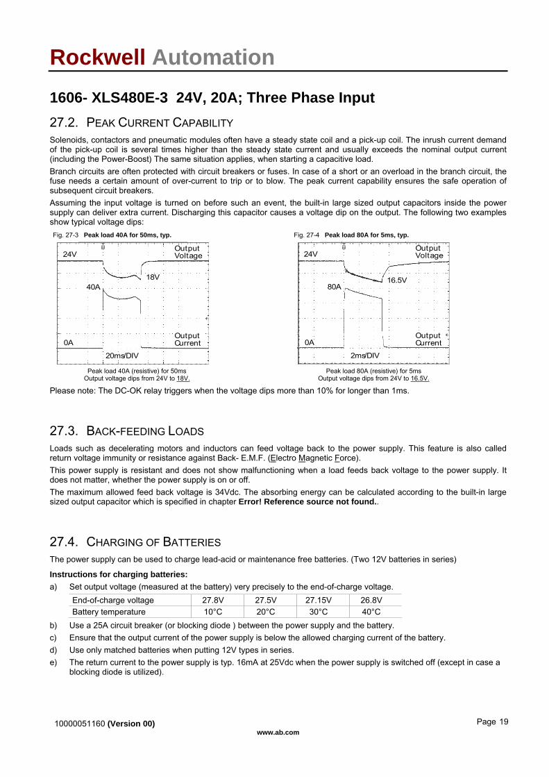
Rockwell Automation 1606- XLS480E-3 24V, 20A; Three Phase Input 27.2. PEAK CURRENT CAPABILITY Solenoids, contactors and pneumatic modules often have a steady state coil and a pick-up coil. The inrush current demand of the pick-up coil is several times higher than the steady state current and usually exceeds the nominal output current (including the Power-Boost) The same situation applies, when starting a capacitive load. Branch circuits are often protected with circuit breakers or fuses. In case of a short or an overload in the branch circuit, the fuse needs a certain amount of over-current to trip or to blow. The peak current capability ensures the safe operation of subsequent circuit breakers. Assuming the input voltage is turned on before such an event, the built-in large sized output capacitors inside the power supply can deliver extra current. Discharging this capacitor causes a voltage dip on the output. The following two examples show typical voltage dips: Fig. 27-3 Peak load 40A for 50ms, typ. Fig. 27-4 Peak load 80A for 5ms, typ.
20ms/DIV
OutputVoltage
OutputCurrent
24V
0A
40A18V
2ms/DIV
OutputVoltage
OutputCurrent
24V
0A
80A16.5V
Peak load 40A (resistive) for 50ms
Output voltage dips from 24V to 18V. Peak load 80A (resistive) for 5ms
Output voltage dips from 24V to 16.5V.
Please note: The DC-OK relay triggers when the voltage dips more than 10% for longer than 1ms.
27.3. BACK-FEEDING LOADS Loads such as decelerating motors and inductors can feed voltage back to the power supply. This feature is also called return voltage immunity or resistance against Back- E.M.F. (Electro Magnetic Force). This power supply is resistant and does not show malfunctioning when a load feeds back voltage to the power supply. It does not matter, whether the power supply is on or off. The maximum allowed feed back voltage is 34Vdc. The absorbing energy can be calculated according to the built-in large sized output capacitor which is specified in chapter Error! Reference source not found..
27.4. CHARGING OF BATTERIES The power supply can be used to charge lead-acid or maintenance free batteries. (Two 12V batteries in series)
Instructions for charging batteries: a) Set output voltage (measured at the battery) very precisely to the end-of-charge voltage.
End-of-charge voltage 27.8V 27.5V 27.15V 26.8V Battery temperature 10°C 20°C 30°C 40°C
b) Use a 25A circuit breaker (or blocking diode ) between the power supply and the battery. c) Ensure that the output current of the power supply is below the allowed charging current of the battery. d) Use only matched batteries when putting 12V types in series. e) The return current to the power supply is typ. 16mA at 25Vdc when the power supply is switched off (except in case a
blocking diode is utilized).
10000051160 (Version 00) www.ab.com
Page 19

Rockwell Automation 1606- XLS480E-3 24V, 20A; Three Phase Input 27.5. OUTPUT CIRCUIT BREAKERS Standard miniature circuit breakers (MCBs) can be used for branch protection. Ensure that the MCB is rated for DC voltage, too. The following tests show which circuit breakers the power supply typically trips. Circuit breakers have huge tolerances in their tripping behavior. Therefore, these typical tests can only be used as a recommendation or for comparing two different power supplies. Furthermore, the loop impedance has a major influence on whether a breaker trips or not. Two tests were performed, representing typical situations: Test 1: Short circuit with S1 on the power supply end of the cable (loop impedance approx. 20mOhm)
Fig. 27-5 Branch protectors, test circuit 1
CircuitBreakerPower
SupplyAC
DC
+
-
I
Load+
-S1
Parameters: Input voltage:3x 400Vac, load current: 0A Tripping time shorter than 5s. The following circuit breaker tripped during the test: A- or Z- Characteristic:: equal or smaller 25A B- Characteristic: equal or smaller 16A C- Characteristic: equal or smaller 10A
Test 2: Short circuit with S1 on the load end (additional impedance included; represents longer load wire length).
Fig. 27-6 Branch protectors, test circuit 2
R
CircuitBreakerPower
SupplyAC
DC
+
-
I
S1 Load+
-
Parameters: Input voltage: 3x 400Vac, load current: 0A Tripping time shorter than 5s. The following circuit breaker tripped during the test: A- or Z- Characteristic:: ≤ 16A and R< 82mOhm B- Characteristic: ≤ 6A and R< 180mOhm C- Characteristic: ≤ 8A and R<= 150mOhm What does this resistance mean in wire length?
0.5mm2 0.7mm2 1.0mm2 1.5mm2 2.5mm2 4.0mm2 82mOhm 2.3m 3.2m 4.6m 6.9m 11.4m 18.3m 150mOhm 4.2m 5.9m 8.4m 12.5m 20.9m 33.4m
180mOhm 5.0m 7.0m 10.0m 15.0m 25.1m 40.1m
Example: Which wire gauge must be used to trip a B-Characteristic circuit breaker with a rating of 6A? The load wire length is 21m. Answer: A 6A B-Characteristic circuit breaker requires a loop impedance of less than 180mOhm (test results). The wire length table shows that up to 25.1m wire with a cross section of 2.5mm2 are below 180mOhm. A wire not smaller than 2.5mm2 shall be used.
10000051160 (Version 00) www.ab.com
Page 20

Rockwell Automation 1606- XLS480E-3 24V, 20A; Three Phase Input
27.6. EXTERNAL INPUT PROTECTION The unit is tested and approved for branch circuits up to 15A (U.S.A.) and 16A (IEC). External protection is only required, if the supplying branch has an ampacity greater than this. In some countries local regulations might apply. Check also local codes and local requirements. If an external fuse is necessary or utilized, a minimum value is required to avoid undesired tripping of the fuse.
B-Characteristic C-Characteristic Ampacity max. 16A (U.S.A.: 15A) 16A (U.S.A.: 15A) min. 6A 3A
27.7. 2-PHASE OPERATION The 1606-XLS480E-3 is specified to operate on two phases.
Fig. 27-7 Wiring diagram 2-phase operation Instructions for 2-ph operation: Reduce output power according to curve. Exceeding the limits results in a thermal shut-down. The specification for EMC performance, hold-up time, losses and output ripple will no longer be valid. Check suitability individually in the application.
DC
L1
L2
PE
L2
L1
L3
Fuse
L3open
Fig. 27-8 2-phase operation, allowed output current Fig. 27-9 2-phase operation, Hold-up time
Allowed Output Current at 24V
0-25 0 20 70°C
5
10
15
20
25
30A
cont inuous
Input Voltage
for typ. 4s
40 60
A... 2x 460 to 552VacB... 2x 340 to 460Vac
B A
0
10
20
30
40
50ms
320 360 400 440 2x480Vac
Input Voltage
Hold-up Time (2-Ph)
24V, 10A, typ.
24V, 20A, typ.
24V, 10A, min.
24V, 20A, min.
10000051160 (Version 00) www.ab.com
Page 21
Rockwell Automation 1606- XLS480E-3 24V, 20A; Three Phase Input
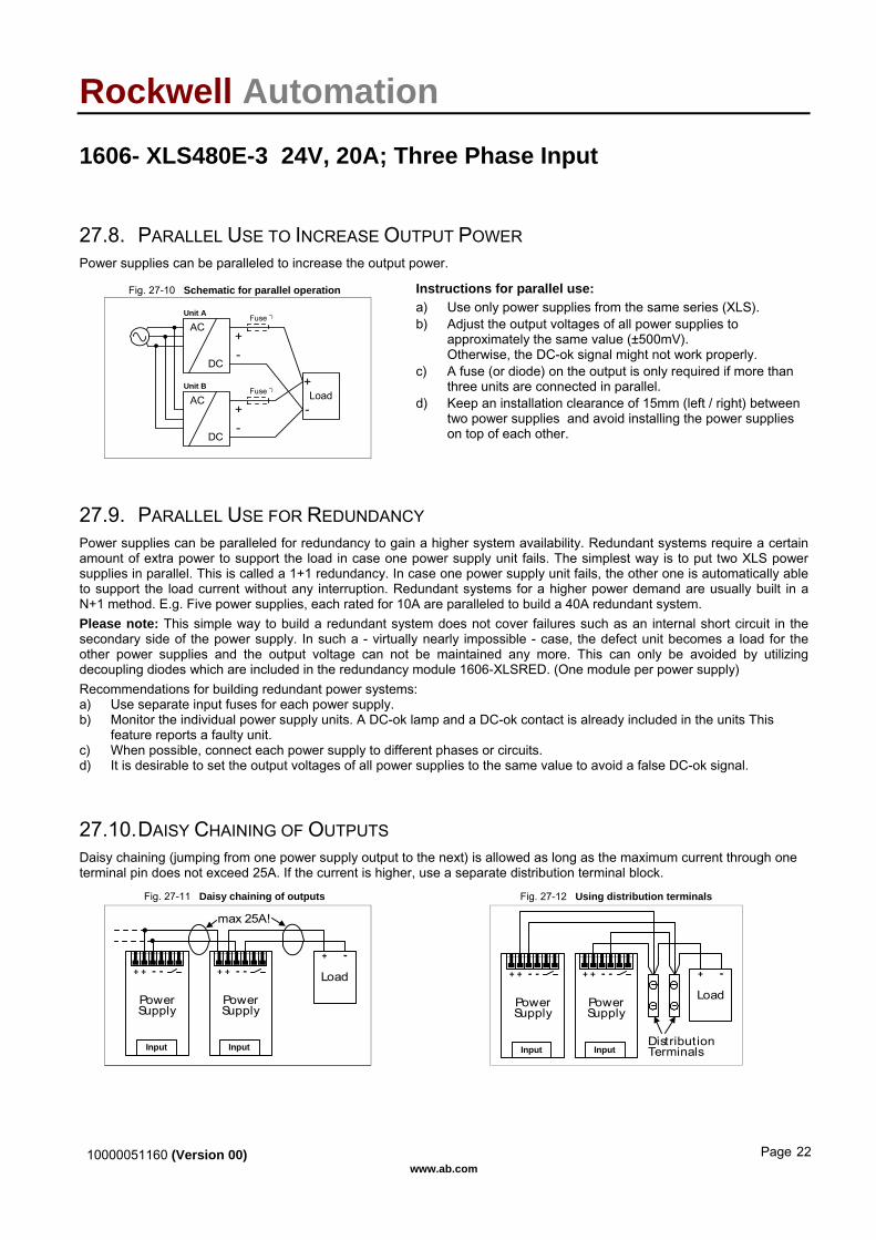
27.8. PARALLEL USE TO INCREASE OUTPUT POWER Power supplies can be paralleled to increase the output power.
Fig. 27-10 Schematic for parallel operation Instructions for parallel use:
Unit B
-+
Load+
-
Fuse *)
Fuse *)
AC
DC
AC
DC-+
Unit A
a) Use only power supplies from the same series (XLS). b) Adjust the output voltages of all power supplies to
approximately the same value (±500mV). Otherwise, the DC-ok signal might not work properly.
c) A fuse (or diode) on the output is only required if more than three units are connected in parallel.
d) Keep an installation clearance of 15mm (left / right) between two power supplies and avoid installing the power supplies on top of each other.
27.9. PARALLEL USE FOR REDUNDANCY Power supplies can be paralleled for redundancy to gain a higher system availability. Redundant systems require a certain amount of extra power to support the load in case one power supply unit fails. The simplest way is to put two XLS power supplies in parallel. This is called a 1+1 redundancy. In case one power supply unit fails, the other one is automatically able to support the load current without any interruption. Redundant systems for a higher power demand are usually built in a N+1 method. E.g. Five power supplies, each rated for 10A are paralleled to build a 40A redundant system. Please note: This simple way to build a redundant system does not cover failures such as an internal short circuit in the secondary side of the power supply. In such a - virtually nearly impossible - case, the defect unit becomes a load for the other power supplies and the output voltage can not be maintained any more. This can only be avoided by utilizing decoupling diodes which are included in the redundancy module 1606-XLSRED. (One module per power supply) Recommendations for building redundant power systems: a) Use separate input fuses for each power supply. b) Monitor the individual power supply units. A DC-ok lamp and a DC-ok contact is already included in the units This
feature reports a faulty unit. c) When possible, connect each power supply to different phases or circuits. d) It is desirable to set the output voltages of all power supplies to the same value to avoid a false DC-ok signal.
27.10. DAISY CHAINING OF OUTPUTS Daisy chaining (jumping from one power supply output to the next) is allowed as long as the maximum current through one terminal pin does not exceed 25A. If the current is higher, use a separate distribution terminal block.
Fig. 27-11 Daisy chaining of outputs Fig. 27-12 Using distribution terminals
PowerSupply
+ + - -
Input
PowerSupply
+ + - -
Input
Load
+ -
max 25A!
PowerSupply
+ + - -
Input
PowerSupply
+ + - -
Input
Load
+ -
DistributionTerminals
10000051160 (Version 00) www.ab.com
Page 22

Rockwell Automation 1606- XLS480E-3 24V, 20A; Three Phase Input 27.11. SERIES OPERATION The power supply can be put in series to increase the output voltage. Fig. 27-13 Schematic for series operation Instructions for use in series:
Unit B
-+
Load+
-
AC
DC
AC
DC-+
Unit A
Earth(see notes)
a) It is possible to connect as many units in series as needed, providing the sum of the output voltage does not exceed 150Vdc.
b) Warning ! Voltages with a potential above 60Vdc are not SELV any more and can be dangerous. Such voltages must be installed with a protection against touching.
c) For serial operation use power supplies of the same type. d) Earthing of the output is required when the sum of the output
voltage is above 60Vdc. e) Keep an installation clearance of 15mm (left/right) between two
power supplies and avoid installing the power supplies on top of each other.
Note: Avoid return voltage (e.g. from a decelerating motor or battery) which is applied to the output terminals.
27.12. INDUCTIVE AND CAPACITIVE LOADS The unit is designed to supply any kind of load, including unlimited capacitive and inductive loads.
27.13. USE IN A TIGHTLY SEALED ENCLOSURE When the power supply is installed in a tightly sealed enclosure, the temperature inside the enclosure will be higher than outside. The inside temperature defines the ambient temperature for the power supply. Results from such an installation: Power supply is placed in the middle of the box, no other heat producer inside the box Enclosure: Typ IP66 Box PK 9519 100, plastic, 180x180x165mm Load: 24V, 16A; (=80%) load is placed outside the box Input: 3x 400Vac Temperature inside enclosure: 55.9°C (in the middle of the right side of the power supply with a distance of 2cm) Temperature outside enclosure: 24.9°C Temperature rise: 31°C
10000051160 (Version 00) www.ab.com
Page 23

Rockwell Automation 1606- XLS480E-3 24V, 20A; Three Phase Input
10000051160 (Version 00) www.ab.com
Page 24
27.14. MOUNTING ORIENTATIONS Mounting orientations other than input terminals on the bottom and output on the top require a reduction in continuous output power or a limitation in the max. allowed ambient temperature. The amount of reduction influences the lifetime expectancy of the power supply. Therefore, two different derating curves for continuous operation can be found below: Curve A1 Recommended output current. Curve A2 Max allowed output current (results approx. in half the lifetime expectancy of A1). Fig. 27-12 Mounting Orientation A Standard Orientation
PowerSupply
OUTPUT
INPUT
Output Current
010 20 30 40 60°C
4
1216
20A
50
A1
8
Ambient Temperature
Fig. 27-13 Mounting Orientation B (Upside down)
PowerSupply
OUTPUT
INPUT
Output Current
010 20 30 40 60°C
4
1216
20A
50
8A1
A2
Ambient Temperature
Fig. 27-14 Mounting Orientation C (Table-top mounting)
Output Current
010 20 30 40 60°C
4
1216
20A
50
8A1
A2
Ambient Temperature
Fig. 27-15 Mounting Orientation D (Horizontal cw) Pow
erSupply
OU
TPUT
INPU
T
Output Current
010 20 30 40 60°C
4
1216
20A
50
8 A1
A2
Ambient Temperature
Fig. 27-16 Mounting Orientation E (Horizontal ccw)
Pow
erSu
pply
OU
TPU
T
INPU
T
Output Current
010 20 30 40 60°C
4
1216
20A
50
8 A1
A2
Ambient Temperature