Embed Size (px)
Citation preview

DS GOLF CARSGASOLINE/ELECTRIC
MANUAL NUMBER 1019684010199B0312A
1998-1999MAINTENANCES E R V I C E
MANUAL
EDITION CODE

FORWARD
Club Car golf cars are designed and built to provide maximum efficiency and performance. However, propermaintenance and repair is essential for achieving maximum service life and continued safe and reliable oper-ation. This maintenance and service manual provides detailed procedures for the maintenance and repair ofthose components that are common to all Club Car DS Golf Cars, and should be used in conjunction with theappropriate maintenance and service supplement. The supplement will provide maintenance and repair pro-cedures for those components specific to a particular type of vehicle. If you do not have the appropriate sup-plement for your vehicle(s), you may obtain one of the following from your Club Car distributor:
This manual and the supplement should be read prior to servicing the vehicle. The procedures provided mustbe properly implemented, and the CAUTION, WARNING, and DANGER statements must be heeded.
This manual was written for the vehicle mechanic who already possesses basic knowledge and skills in elec-trical and mechanical repair. If the mechanic does not have such basic knowledge and skills, attempted ser-vice or repairs to the vehicle may render it unsafe. For this reason, we advise that all repairs and/or servicebe performed by an authorized Club Car distributor’s/dealer’s representative or by a Club Car factory trainedtechnician.
It is the policy of Club Car, Inc. to assist its distributors and dealers in continually updating their serviceknowledge and facilities so they can provide prompt and efficient service for vehicle owners. Regional techni-cal representatives, golf car service seminars, periodic service bulletins, maintenance and service manuals,and other service publications also represent Club Car’s continuing commitment to customer support.
This service manual, used in conjunction with the appropriate supplement, covers all aspects of typical DSGolf Car service. However, unique situations do sometimes arise when servicing a golf car. If it appears thata service question is not answered in this manual or the supplement, you may write to us at: Club Car, Inc.;P.O. Box 204658; Augusta, GA 30917; Attention: Technical Services, or contact a Club Car Technical Servicerepresentative at (706) 863-3000, extension 3580.
©1999, 2012 Club Car, Inc.
Club Car, Armorflex, PowerDrive, PowerDrive Plus, and Tranquility are registered trademarks of Club Car, Inc.
This manual effective August 1, 1998
1998/1999 PowerDrive System 48 Vehicle Maintenance & Service Supplement Publication Part No. 101968404
1998/1999 PowerDrive Plus Vehicle Maintenance & Service Supplement Publication Part No. 101968405
1998/1999 V-Glide 36-Volt Vehicle Maintenance & Service Supplement Publication Part No. 101968406
1998/1999 FE 290 Gasoline Vehicle Maintenance & Service Supplement Publication Part No. 101968407
1998/1999 DS Golf Car Maintenance and Service Manual Page i
• READ SECTION 1 - SAFETY - BEFORE ATTEMPTING ANY SERVICE ON THIS VEHICLE.
• BEFORE SERVICING VEHICLE, READ COMPLETE SECTION(S) AND ANY REFERENCEDINFORMATION RELEVANT TO SERVICE OR REPAIR TO BE PERFORMED.
• THIS MANUAL REPRESENTS THE MOST CURRENT INFORMATION AT TIME OFPUBLICATION. CLUB CAR, INC. IS CONTINUALLY WORKING TO FURTHER IMPROVE OURVEHICLES AND OTHER PRODUCTS. THESE IMPROVEMENTS MAY AFFECT SERVICINGPROCEDURES. ANY MODIFICATION AND/OR SIGNIFICANT CHANGE IN SPECIFICATIONS ORPROCEDURES WILL BE FORWARDED TO ALL CLUB CAR DISTRIBUTORS AND DEALERS ANDWILL, WHEN APPLICABLE, APPEAR IN FUTURE EDITIONS OF THIS MANUAL.
• DAMAGE TO A VEHICLE OR COMPONENT THEREOF NOT RESULTING FROM A DEFECT ORWHICH OCCURS DUE TO UNREASONABLE OR UNINTENDED USE, OVERLOADING, ABUSE,OR NEGLECT (INCLUDING FAILURE TO PROVIDE REASONABLE OR NECESSARYMAINTENANCE AS INSTRUCTED IN THE VEHICLE OWNER’S MANUAL), ACCIDENT ORALTERATION, INCLUDING INCREASING VEHICLE SPEED BEYOND FACTORYSPECIFICATIONS OR MODIFICATIONS WHICH AFFECT THE STABILITY OF THE VEHICLE ORTHE OPERATION THEREOF, WILL VOID THE WARRANTY.
• CLUB CAR, INC. RESERVES THE RIGHT TO CHANGE SPECIFICATIONS AND DESIGNS ATANY TIME WITHOUT NOTICE AND WITHOUT INCURRING ANY OBLIGATION OR LIABILITYWHATSOEVER.
• THERE ARE NO WARRANTIES EXPRESSED OR IMPLIED IN THIS MANUAL. SEE THE LIMITEDWARRANTY FOUND IN THE VEHICLE OWNER’S MANUAL OR WRITE TO CLUB CAR, INC.
WARNING
NOTE
Page ii 1998/1999 DS Golf Car Maintenance and Service Manual
1
2
3
4
5
6
CONTENTS
SAFETY SECTION
General Warning ............................................................................................................................... 1-1
VEHICLE SPECIFICATIONS SECTION
General Information .......................................................................................................................... 2-1
GENERAL INFORMATION SECTION
Model Identification ........................................................................................................................... 3-1
Safety Committee ............................................................................................................................. 3-1
Pre-Operation Checklist .................................................................................................................... 3-2
Controls ............................................................................................................................................ 3-3
Driving Instructions ........................................................................................................................... 3-9
Towing ............................................................................................................................................... 3-11
Transporting on a Trailer ................................................................................................................... 3-11
Storage - Gasoline Vehicle ............................................................................................................... 3-12
Storage - Electric Vehicle .................................................................................................................. 3-13
BODY AND TRIM SECTION
General Information .......................................................................................................................... 4-2
Front and Rear Body Repair ............................................................................................................. 4-2
Seat .................................................................................................................................................. 4-4
Front Body ........................................................................................................................................ 4-4
Rear Body ......................................................................................................................................... 4-6
Floormat ............................................................................................................................................ 4-8
ACCELERATOR AND BRAKE PEDAL GROUP SECTION
General Information .......................................................................................................................... 5-1
Pedal Group Adjustment.................................................................................................................... 5-2
Pedal Group Disassembly and Assembly ......................................................................................... 5-8
WHEEL BRAKE ASSEMBLIES SECTION
Removal and Cleaning of Wheel Brake Assemblies ......................................................................... 6-3
Installing the Brake Shoes ................................................................................................................ 6-5
Adjusting the Brakes ......................................................................................................................... 6-8
Removal and Installation of Brake Assembly .................................................................................... 6-8
1998/1999 DS Golf Car Maintenance and Service Manual Page iii

7
8
9
STEERING AND FRONT SUSPENSION SECTION
General Information - Steering........................................................................................................... 7-1
Steering Wheel ................................................................................................................................. 7-2
Steering Column ............................................................................................................................... 7-2
Steering Adjustment .......................................................................................................................... 7-6
Rack and Pinion ................................................................................................................................ 7-7
Tie Rod and Drag Link ...................................................................................................................... 7-10
Front Suspension .............................................................................................................................. 7-12
Front Suspension Components ........................................................................................................ 7-14
Front Wheel Bearings and Hubs ....................................................................................................... 7-18
WHEELS AND TIRES SECTION
General Information ........................................................................................................................... 8-1
Wheel Removal, Repair and Installation ........................................................................................... 8-2
REAR SUSPENSION SECTION
General Information .......................................................................................................................... 9-1
Shock Absorbers ............................................................................................................................... 9-3
Leaf Springs ...................................................................................................................................... 9-3
Page iv 1998/1999 DS Golf Car Maintenance and Service Manual
1
SECTION 1–SAFETY
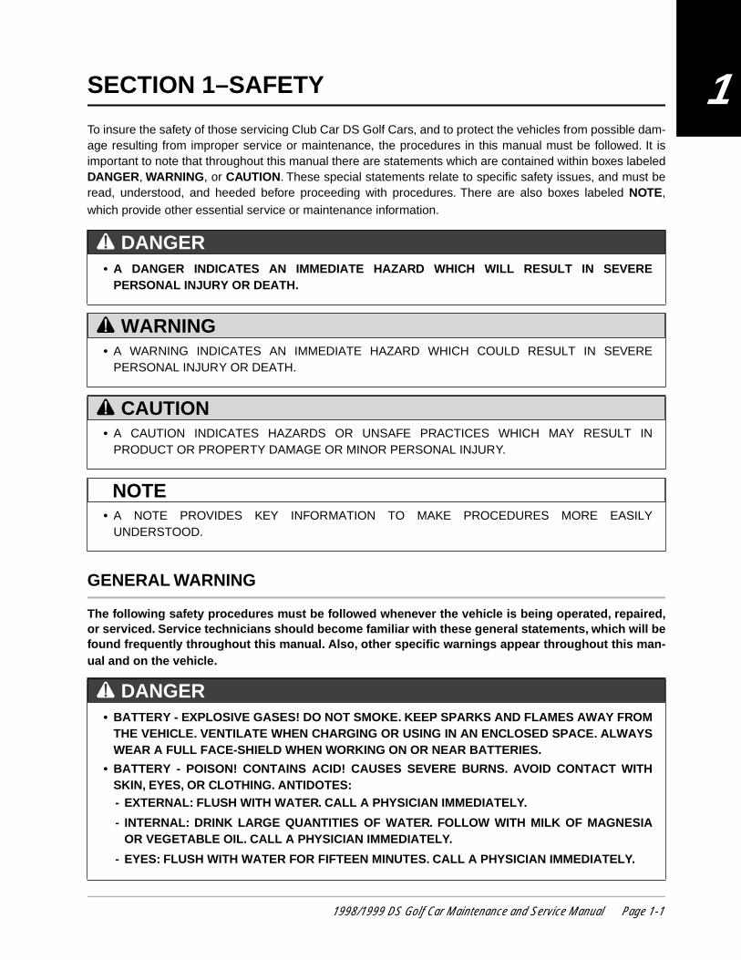
To insure the safety of those servicing Club Car DS Golf Cars, and to protect the vehicles from possible dam-age resulting from improper service or maintenance, the procedures in this manual must be followed. It isimportant to note that throughout this manual there are statements which are contained within boxes labeledDANGER, WARNING, or CAUTION. These special statements relate to specific safety issues, and must beread, understood, and heeded before proceeding with procedures. There are also boxes labeled NOTE,which provide other essential service or maintenance information.
GENERAL WARNING
The following safety procedures must be followed whenever the vehicle is being operated, repaired,or serviced. Service technicians should become familiar with these general statements, which will befound frequently throughout this manual. Also, other specific warnings appear throughout this man-ual and on the vehicle.
• A DANGER INDICATES AN IMMEDIATE HAZARD WHICH WILL RESULT IN SEVEREPERSONAL INJURY OR DEATH.
• A WARNING INDICATES AN IMMEDIATE HAZARD WHICH COULD RESULT IN SEVEREPERSONAL INJURY OR DEATH.
• A CAUTION INDICATES HAZARDS OR UNSAFE PRACTICES WHICH MAY RESULT INPRODUCT OR PROPERTY DAMAGE OR MINOR PERSONAL INJURY.
• A NOTE PROVIDES KEY INFORMATION TO MAKE PROCEDURES MORE EASILYUNDERSTOOD.
• BATTERY - EXPLOSIVE GASES! DO NOT SMOKE. KEEP SPARKS AND FLAMES AWAY FROMTHE VEHICLE. VENTILATE WHEN CHARGING OR USING IN AN ENCLOSED SPACE. ALWAYSWEAR A FULL FACE-SHIELD WHEN WORKING ON OR NEAR BATTERIES.
• BATTERY - POISON! CONTAINS ACID! CAUSES SEVERE BURNS. AVOID CONTACT WITHSKIN, EYES, OR CLOTHING. ANTIDOTES:- EXTERNAL: FLUSH WITH WATER. CALL A PHYSICIAN IMMEDIATELY.
- INTERNAL: DRINK LARGE QUANTITIES OF WATER. FOLLOW WITH MILK OF MAGNESIAOR VEGETABLE OIL. CALL A PHYSICIAN IMMEDIATELY.
- EYES: FLUSH WITH WATER FOR FIFTEEN MINUTES. CALL A PHYSICIAN IMMEDIATELY.
DANGER
WARNING
CAUTION
NOTE
DANGER
1998/1999 DS Golf Car Maintenance and Service Manual Page 1-1
SAFETY General Warning
1
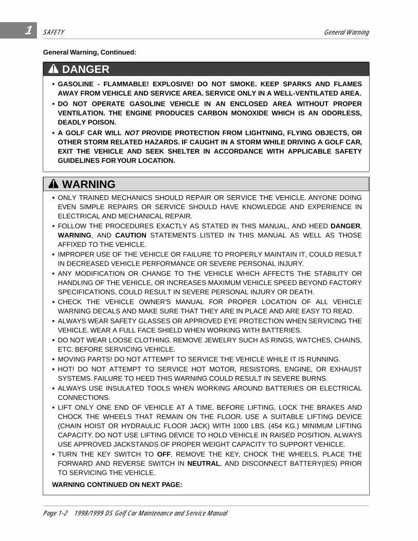
General Warning, Continued:
• GASOLINE - FLAMMABLE! EXPLOSIVE! DO NOT SMOKE. KEEP SPARKS AND FLAMESAWAY FROM VEHICLE AND SERVICE AREA. SERVICE ONLY IN A WELL-VENTILATED AREA.
• DO NOT OPERATE GASOLINE VEHICLE IN AN ENCLOSED AREA WITHOUT PROPERVENTILATION. THE ENGINE PRODUCES CARBON MONOXIDE WHICH IS AN ODORLESS,DEADLY POISON.
• A GOLF CAR WILL NOT PROVIDE PROTECTION FROM LIGHTNING, FLYING OBJECTS, OROTHER STORM RELATED HAZARDS. IF CAUGHT IN A STORM WHILE DRIVING A GOLF CAR,EXIT THE VEHICLE AND SEEK SHELTER IN ACCORDANCE WITH APPLICABLE SAFETYGUIDELINES FOR YOUR LOCATION.
• ONLY TRAINED MECHANICS SHOULD REPAIR OR SERVICE THE VEHICLE. ANYONE DOINGEVEN SIMPLE REPAIRS OR SERVICE SHOULD HAVE KNOWLEDGE AND EXPERIENCE INELECTRICAL AND MECHANICAL REPAIR.
• FOLLOW THE PROCEDURES EXACTLY AS STATED IN THIS MANUAL, AND HEED DANGER,WARNING, AND CAUTION STATEMENTS LISTED IN THIS MANUAL AS WELL AS THOSEAFFIXED TO THE VEHICLE.
• IMPROPER USE OF THE VEHICLE OR FAILURE TO PROPERLY MAINTAIN IT, COULD RESULTIN DECREASED VEHICLE PERFORMANCE OR SEVERE PERSONAL INJURY.
• ANY MODIFICATION OR CHANGE TO THE VEHICLE WHICH AFFECTS THE STABILITY ORHANDLING OF THE VEHICLE, OR INCREASES MAXIMUM VEHICLE SPEED BEYOND FACTORYSPECIFICATIONS, COULD RESULT IN SEVERE PERSONAL INJURY OR DEATH.
• CHECK THE VEHICLE OWNER’S MANUAL FOR PROPER LOCATION OF ALL VEHICLEWARNING DECALS AND MAKE SURE THAT THEY ARE IN PLACE AND ARE EASY TO READ.
• ALWAYS WEAR SAFETY GLASSES OR APPROVED EYE PROTECTION WHEN SERVICING THEVEHICLE. WEAR A FULL FACE SHIELD WHEN WORKING WITH BATTERIES.
• DO NOT WEAR LOOSE CLOTHING. REMOVE JEWELRY SUCH AS RINGS, WATCHES, CHAINS,ETC. BEFORE SERVICING VEHICLE.
• MOVING PARTS! DO NOT ATTEMPT TO SERVICE THE VEHICLE WHILE IT IS RUNNING.
• HOT! DO NOT ATTEMPT TO SERVICE HOT MOTOR, RESISTORS, ENGINE, OR EXHAUSTSYSTEMS. FAILURE TO HEED THIS WARNING COULD RESULT IN SEVERE BURNS.
• ALWAYS USE INSULATED TOOLS WHEN WORKING AROUND BATTERIES OR ELECTRICALCONNECTIONS.
• LIFT ONLY ONE END OF VEHICLE AT A TIME. BEFORE LIFTING, LOCK THE BRAKES ANDCHOCK THE WHEELS THAT REMAIN ON THE FLOOR. USE A SUITABLE LIFTING DEVICE(CHAIN HOIST OR HYDRAULIC FLOOR JACK) WITH 1000 LBS. (454 KG.) MINIMUM LIFTINGCAPACITY. DO NOT USE LIFTING DEVICE TO HOLD VEHICLE IN RAISED POSITION. ALWAYSUSE APPROVED JACKSTANDS OF PROPER WEIGHT CAPACITY TO SUPPORT VEHICLE.
• TURN THE KEY SWITCH TO OFF, REMOVE THE KEY, CHOCK THE WHEELS, PLACE THEFORWARD AND REVERSE SWITCH IN NEUTRAL , AND DISCONNECT BATTERY(IES) PRIORTO SERVICING THE VEHICLE.
WARNING CONTINUED ON NEXT PAGE:
DANGER
WARNING
Page 1-2 1998/1999 DS Golf Car Maintenance and Service Manual
SAFETY General Warning
1
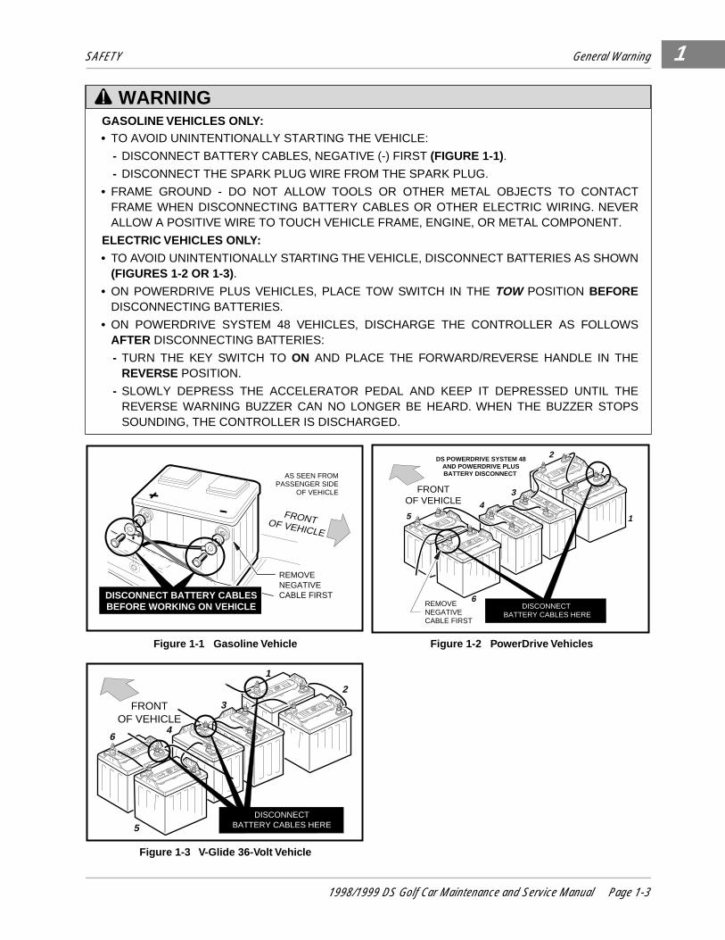
GASOLINE VEHICLES ONLY:• TO AVOID UNINTENTIONALLY STARTING THE VEHICLE:
- DISCONNECT BATTERY CABLES, NEGATIVE (-) FIRST (FIGURE 1-1).
- DISCONNECT THE SPARK PLUG WIRE FROM THE SPARK PLUG.
• FRAME GROUND - DO NOT ALLOW TOOLS OR OTHER METAL OBJECTS TO CONTACTFRAME WHEN DISCONNECTING BATTERY CABLES OR OTHER ELECTRIC WIRING. NEVERALLOW A POSITIVE WIRE TO TOUCH VEHICLE FRAME, ENGINE, OR METAL COMPONENT.
ELECTRIC VEHICLES ONLY:
• TO AVOID UNINTENTIONALLY STARTING THE VEHICLE, DISCONNECT BATTERIES AS SHOWN(FIGURES 1-2 OR 1-3).
• ON POWERDRIVE PLUS VEHICLES, PLACE TOW SWITCH IN THE TOW POSITION BEFOREDISCONNECTING BATTERIES.
• ON POWERDRIVE SYSTEM 48 VEHICLES, DISCHARGE THE CONTROLLER AS FOLLOWSAFTER DISCONNECTING BATTERIES:
- TURN THE KEY SWITCH TO ON AND PLACE THE FORWARD/REVERSE HANDLE IN THEREVERSE POSITION.
- SLOWLY DEPRESS THE ACCELERATOR PEDAL AND KEEP IT DEPRESSED UNTIL THEREVERSE WARNING BUZZER CAN NO LONGER BE HEARD. WHEN THE BUZZER STOPSSOUNDING, THE CONTROLLER IS DISCHARGED.
Figure 1-1 Gasoline Vehicle Figure 1-2 PowerDrive Vehicles
Figure 1-3 V-Glide 36-Volt Vehicle
WARNING
FRONTOF VEHICLE
AS SEEN FROMPASSENGER SIDE
OF VEHICLE
REMOVE NEGATIVECABLE FIRSTDISCONNECT BATTERY CABLES
BEFORE WORKING ON VEHICLE
DS POWERDRIVE SYSTEM 48AND POWERDRIVE PLUSBATTERY DISCONNECT
1
2
34
6
5
FRONTOF VEHICLE
REMOVE NEGATIVECABLE FIRST
DISCONNECT BATTERY CABLES HERE
1
2
3
46
5DISCONNECT
BATTERY CABLES HERE
FRONTOF VEHICLE
1998/1999 DS Golf Car Maintenance and Service Manual Page 1-3

1
2
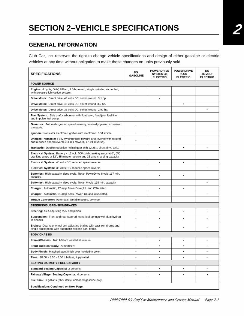
SECTION 2–VEHICLE SPECIFICATIONS
GENERAL INFORMATION
Club Car, Inc. reserves the right to change vehicle specifications and design of either gasoline or electric
vehicles at any time without obligation to make these changes on units previously sold.
SPECIFICATIONS DS GASOLINE
POWERDRIVE SYSTEM 48 ELECTRIC
POWERDRIVE PLUS
ELECTRIC
DS36-VOLT
ELECTRIC
POWER SOURCE
Engine: 4 cycle, OHV, 286 cc, 9.0 hp rated., single cylinder, air cooled, with pressure lubrication system. •
Drive Motor: Direct drive, 48 volts DC, series wound, 3.1 hp. •
Drive Motor: Direct drive, 48 volts DC, shunt wound, 3.2 hp. •
Drive Motor: Direct drive, 36 volts DC, series wound, 2.97 hp. •
Fuel System: Side draft carburetor with float bowl, fixed jets, fuel filter, and impulse fuel pump. •
Governor: Automatic ground speed sensing, internally geared in unitized transaxle. •
Ignition: Transistor electronic ignition with electronic RPM limiter. •
Unitized Transaxle: Fully synchronized forward and reverse with neutral and reduced speed reverse (11.8:1 forward, 17.1:1 reverse). •
Transaxle: Double reduction helical gear with 12.28:1 direct drive axle. • • •
Electrical System: Battery - 12 volt, 500 cold cranking amps at 0°, 650 cranking amps at 32°, 85 minute reserve and 35 amp charging capacity. •
Electrical System: 48 volts DC, reduced speed reverse. • •
Electrical System: 36 volts DC, reduced speed reverse. •
Batteries: High capacity, deep cycle, Trojan PowerDrive 8 volt, 117 min. capacity. • •
Batteries: High capacity, deep cycle, Trojan 6 volt, 115 min. capacity. •
Charger: Automatic, 17 amp PowerDrive; UL and CSA listed. • •
Charger: Automatic, 21 amp Accu-Power; UL and CSA listed. •
Torque Converter: Automatic, variable speed, dry type. •
STEERING/SUSPENSION/BRAKES
Steering: Self-adjusting rack and pinion. • • • •
Suspension: Front and rear tapered mono-leaf springs with dual hydrau-lic shocks. • • • •
Brakes: Dual rear wheel self-adjusting brakes with cast iron drums and single brake pedal with automatic-release park brake. • • • •
BODY/CHASSIS
Frame/Chassis: Twin I-Beam welded aluminum. • • • •
Front and Rear Body: Armorflex® • • • •
Body Finish: Matched paint finish over molded-in color. • • • •
Tires: 18.00 x 8.50 - 8.00 tubeless, 4 ply rated. • • • •
SEATING CAPACITY/FUEL CAPACITY
Standard Seating Capacity: 2 persons • • • •
Fairway Villager Seating Capacity: 4 persons • • • •
Fuel Tank: 7 gallons (26.5 liters), unleaded gasoline only. •
Specifications Continued on Next Page.
1998/1999 DS Golf Car Maintenance and Service Manual Page 2-1

VEHICLE SPECIFICATIONS General Information
2
DIMENSIONS/WEIGHT
Overall Length 91-1/2"(232 cm)
91-1/2"(232 cm)
91-1/2"(232 cm)
91-1/2"(232 cm)
Overall Width 47-1/4"(120 cm)
47-1/4"(120 cm)
47-1/4"(120 cm)
47-1/4"(120 cm)
Overall Height: At Steering Wheel. 48"(122 cm)
48"(122 cm)
48"(122 cm)
48"(122 cm)
Wheelbase 65-1/2"(166 cm)
65-1/2"(166 cm)
65-1/2"(166 cm)
65-1/2"(166 cm)
Ground Clearance 4-1/2"(11 cm)
4-1/2"(11 cm)
4-1/2"(11 cm)
4-1/2"(11 cm)
Front Wheel Tread 34-1/2"(88 cm)
34-1/2"(88 cm
34-1/2"(88 cm
34-1/2"(88 cm
Rear Wheel Tread 38-1/2"(98 cm)
38-1/2"(98 cm)
38-1/2"(98 cm)
38-1/2"(98 cm)
Weight: Standard electric vehicle (without batteries) 455 lbs.(206 kg)
477 lbs.(216 kg)
448 lbs.(203 kg)
Weight: Fairway Villager electric vehicle (without batteries) 495 lbs.(225 kg)
517 lbs.(235 kg) N/A
Weight: Standard gasoline powered vehicle (dry, without battery) 598 lbs.(271 kg.)
Weight: Fairway Villager gasoline powered vehicle (dry) 638 lbs.(289 kg.)
Forward Speed: At 2700 rpm 12 - 15 mph(19 - 24 kph)
12 - 15 mph(19 - 24 kph)
12 - 15 mph(19 - 24 kph)
12 - 15 mph(19 - 24 kph)
Clearance Circle (diameter) 17'-6"(533 cm)
17'-6"(533 cm)
17'-6"(533 cm)
17'-6"(533 cm)
Braking Distance: At 12 mph (19 kph) 14'(427 cm)
14'(427 cm)
14'(427 cm)
14'(427 cm)
SPECIFICATIONS DS GASOLINE
POWERDRIVE SYSTEM 48 ELECTRIC
POWERDRIVE PLUS
ELECTRIC
DS36-VOLT
ELECTRIC
Page 2-2 1998/1999 DS Golf Car Maintenance and Service Manual
3
SECTION 3–GENERAL INFORMATION
There are four DS Golf Car models: the DS gasoline powered vehicle, the DS V-Glide 36-volt electric poweredvehicle, the DS PowerDrive System 48 (48-volt) electric vehicle, and the DS PowerDrive Plus (48-volt) electricvehicle with motor braking. Throughout this manual, important features unique to each model are highlighted. Weurge the owner/operator to read and understand this manual, and to pay special attention to the features specificto his/her vehicle(s).
MODEL IDENTIFICATION
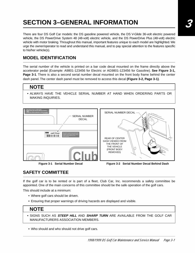
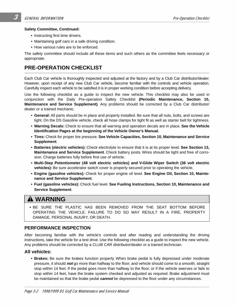
The serial number of the vehicle is printed on a bar code decal mounted on the frame directly above theaccelerator pedal (Example: A9801-123456 for Electric or AG9801-123456 for Gasoline). See Figure 3-1,Page 3-1. There is also a second serial number decal mounted on the front body frame behind the centerdash panel. The center dash panel must be removed to access this decal (Figure 3-2, Page 3-1) .
SAFETY COMMITTEE
If the golf car is to be rented or is part of a fleet, Club Car, Inc. recommends a safety committee beappointed. One of the main concerns of this committee should be the safe operation of the golf cars.
This should include at a minimum:
• Where golf cars should be driven.
• Ensuring that proper warnings of driving hazards are displayed and visible.
• Who should and who should not drive golf cars.
• ALWAYS HAVE THE VEHICLE SERIAL NUMBER AT HAND WHEN ORDERING PARTS ORMAKING INQUIRIES.
Figure 3-1 Serial Number Decal Figure 3-2 Serial Number Decal Behind Dash
• SIGNS SUCH AS STEEP HILL AND SHARP TURN ARE AVAILABLE FROM THE GOLF CARMANUFACTURERS ASSOCIATION MEMBERS.
NOTE
This vehicle is covered by one or more of thefollowing U.S. Patents as applicable: D271008D292899, 4343503, 4539162, 4637270, 48218274826467, 5042519, 5083736 and otherpatents pendings.
ClubGOGO
SERIAL NUMBER
A9801-123456P O BOX 204658AUGUSTA GA 30917
Club CarR
l Help speed up play.l Dispose of litter properly.
Club Car, Inc.
SERIAL NUMBERDECAL
SE
RIA
L N
UM
BE
R
A98
12-5
8394
7
P O
B
OX
204
658
AU
GU
ST
A
GA
30
917
Clu
b C
arR
REAR OF CENTERDASH VIEWED FROM
THE FRONT OFTHE VEHICLE(FRONT BODY
REMOVED)
SERIAL NUMBER DECAL
NOTE
1998/1999 DS Golf Car Maintenance and Service Manual Page 3-1
GENERAL INFORMATION Pre-Operation Checklist
3
Safety Committee, Continued:
• Instructing first time drivers.
• Maintaining golf cars in a safe driving condition.
• How various rules are to be enforced.
The safety committee should include all these items and such others as the committee feels necessary orappropriate.
PRE-OPERATION CHECKLIST
Each Club Car vehicle is thoroughly inspected and adjusted at the factory and by a Club Car distributor/dealer.However, upon receipt of any new Club Car vehicle, become familiar with the controls and vehicle operation.Carefully inspect each vehicle to be satisfied it is in proper working condition before accepting delivery.
Use the following checklist as a guide to inspect the new vehicle. This checklist may also be used inconjunction with the Daily Pre-operation Safety Checklist (Periodic Maintenance, Section 10,Maintenance and Service Supplement) . Any problems should be corrected by a Club Car distributor/dealer or a trained mechanic.
• General: All parts should be in place and properly installed. Be sure that all nuts, bolts, and screws aretight. On the DS Gasoline vehicle, check all hose clamps for tight fit as well as starter belt for tightness.
• Warning Decals: Check to ensure that all warning and operation decals are in place. See the VehicleIdentification Pages at the beginning of the Vehicle Owner’s Manual.
• Tires: Check for proper tire pressure. See Vehicle Capacities, Section 10, Maintenance and ServiceSupplement .
• Batteries (electric vehicles): Check electrolyte to ensure that it is at its proper level. See Section 13,Maintenance and Service Supplement . Check battery posts. Wires should be tight and free of corro-sion. Charge batteries fully before first use of vehicle.
• Multi-Step Potentiometer (48 volt electric vehicles) and V-Glide Wiper Switch (36 volt electricvehicles): Be sure accelerator switch cover is properly secured prior to operating the vehicle.
• Engine (gasoline vehicles): Check for proper engine oil level. See Engine Oil, Section 10, Mainte-nance and Service Supplement .
• Fuel (gasoline vehicles): Check fuel level. See Fueling Instructions, Section 10, Maintenance andService Supplement .
PERFORMANCE INSPECTIONAfter becoming familiar with the vehicle’s controls and after reading and understanding the drivinginstructions, take the vehicle for a test drive. Use the following checklist as a guide to inspect the new vehicle.Any problems should be corrected by a CLUB CAR distributor/dealer or a trained technician.
All vehicles:• Brakes: Be sure the brakes function properly. When brake pedal is fully depressed under moderate
pressure, it should not go more than halfway to the floor, and vehicle should come to a smooth, straightstop within 14 feet. If the pedal goes more than halfway to the floor, or if the vehicle swerves or fails tostop within 14 feet, have the brake system checked and adjusted as required. Brake adjustment mustbe maintained so that the brake pedal cannot be depressed to the floor under any circumstances.
• BE SURE THE PLASTIC HAS BEEN REMOVED FROM THE SEAT BOTTOM BEFOREOPERATING THE VEHICLE. FAILURE TO DO SO MAY RESULT IN A FIRE, PROPERTYDAMAGE, PERSONAL INJURY, OR DEATH.
WARNING
Page 3-2 1998/1999 DS Golf Car Maintenance and Service Manual
GENERAL INFORMATION Controls
3
• Park Brake: When latched, the park brake should lock the wheels and hold the vehicle stationary (onincline of 20% or less). It should release when either the accelerator or brake pedal is depressed.
• Reverse Buzzer: The reverse buzzer should sound as a warning when the vehicle is in REVERSE.
• Steering: The vehicle should be easy to steer and should not have any play in the steering wheel.
• Accelerator: With the key switch ON and the Forward/Reverse handle in the FORWARD position; asthe accelerator pedal is depressed, the engine or motor should start and the vehicle should come upsmoothly to full speed. When pedal is released it should return to the original position and the engine ormotor should stop. All DS (gasoline and electric) vehicles run at reduced speed in REVERSE.
• Governor (gasoline vehicles): Check maximum speed of the vehicle. The vehicle should run at 12-15mph (19-24 kph) on a level surface.
• General: Listen for any unusual noises such as squeaks or rattles. Check the vehicle ride and perfor-mance. Have a CLUB CAR distributor/dealer or a trained mechanic investigate anything unusual.
DS PowerDrive Plus Vehicles with Motor Braking:• Zero Speed Detect: With the vehicle parked on level ground and the park brake disengaged, place the
tow switch in the RUN position and attempt to push the vehicle. It should resist rolling (moving at nomore than 1 or 2 mph) with the Forward/Reverse handle in any position.
• “Pedal Up” Motor Braking: Accelerate the vehicle to full speed and then release the acceleratorpedal. Motor braking should quickly and smoothly slow the vehicle to approximately 9 mph. Motor brak-ing will disengage when vehicle slows to 9 mph.
• “Pedal Down” Motor Braking: Accelerate down an incline with the accelerator pedal depressed.When the vehicle reaches approximately 15 mph, motor braking should engage and moderate vehiclespeed between 15 and 16 mph, depending upon the grade of the hill.
CONTROLS
• DO NOT OPERATE GASOLINE VEHICLE IN AN ENCLOSED AREA WITHOUT PROPERVENTILATION. GASOLINE ENGINES PRODUCE CARBON MONOXIDE GAS, WHICH IS ANODORLESS, DEADLY POISON.
• IF RENTING OR LOANING THE VEHICLE, MAKE SURE DRIVER IS FAMILIAR WITH ALL CONTROLSAND OPERATING PROCEDURES BEFORE ALLOWING THE VEHICLE TO BE DRIVEN.
• DO NOT TAMPER WITH THE GASOLINE VEHICLE GOVERNOR. DOING SO WILL VOID THEWARRANTY, AS WELL AS DAMAGE THE ENGINE AND OTHER COMPONENTS, AND COULDRESULT IN PROPERTY DAMAGE, PERSONAL INJURY, OR DEATH DUE TO ACCIDENT ATUNSAFE SPEED.
• DO NOT MODIFY OR CHANGE THE VEHICLE IN ANY WAY WHICH MIGHT AFFECT ITSSTABILITY OR HANDLING, OR INCREASE MAXIMUM SPEED BEYOND FACTORYSPECIFICATIONS. PROPERTY DAMAGE, PERSONAL INJURY, OR DEATH COULD RESULT.
• DO NOT SHIFT THE FORWARD/REVERSE HANDLE WHILE THE VEHICLE IS MOVING. TOAVOID INJURY TO AN UNSUSPECTING PASSENGER OR DAMAGE TO THE VEHICLE, ALWAYSBRING THE VEHICLE TO A FULL STOP BEFORE SHIFTING THE SWITCH. A BUZZER WILLSOUND AS A WARNING WHEN THE VEHICLE IS IN REVERSE.
• RELEASE THE ACCELERATOR PEDAL AND THEN DEPRESS THE BRAKE PEDAL FIRMLYUNTIL THE VEHICLE STOPS. TO AVOID UNINTENTIONALLY STARTING OR ROLLING THEVEHICLE, SET THE PARK BRAKE, TURN THE KEY SWITCH TO OFF, AND REMOVE THE KEYWHEN LEAVING THE VEHICLE.
DANGER
WARNING
1998/1999 DS Golf Car Maintenance and Service Manual Page 3-3
GENERAL INFORMATION Controls
3
Controls, Continued:
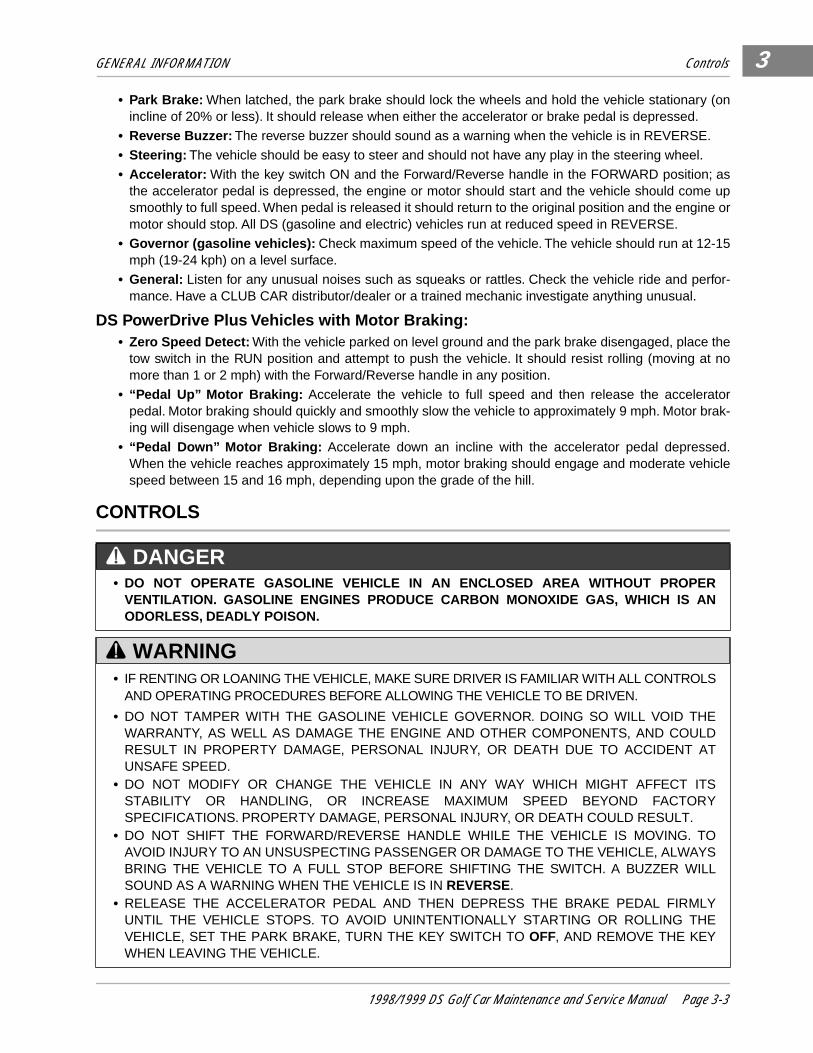
KEY SWITCH The key switch is mounted on the dash to the right of the steering column (Figure 3-3, Page 3-4) . It has twopositions, OFF and ON, which are clearly labeled.
FORWARD/REVERSE CONTROL
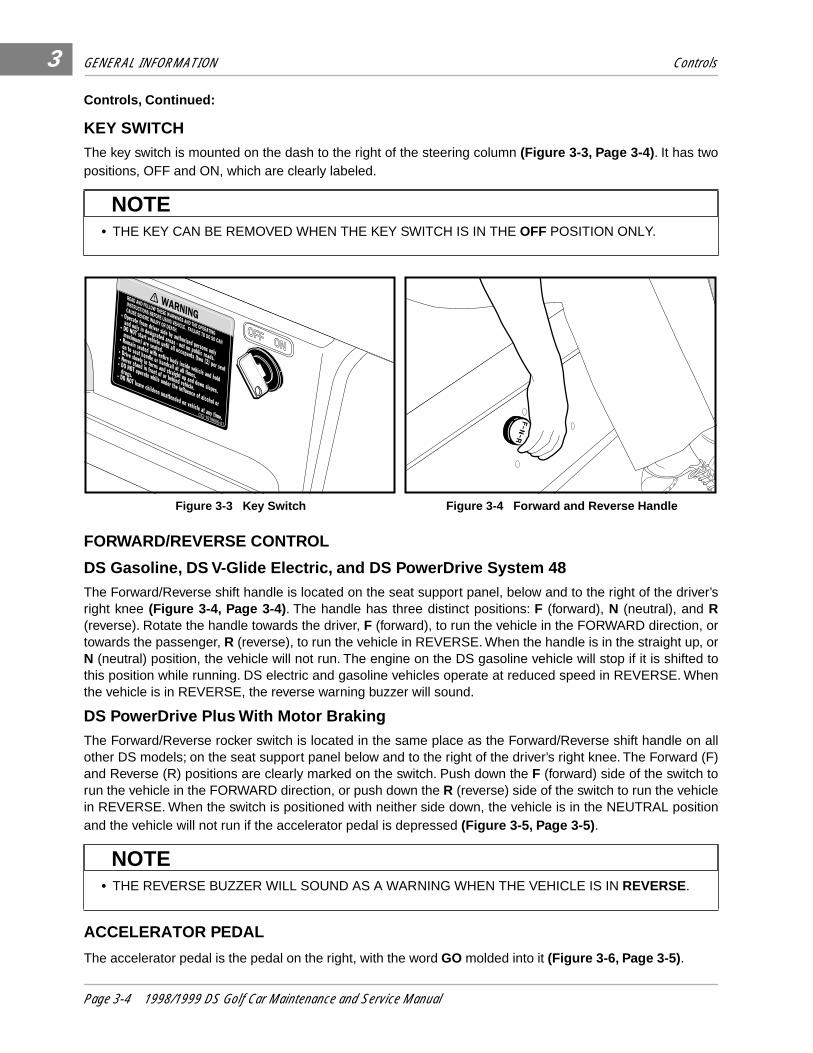
DS Gasoline, DS V-Glide Electric, and DS PowerDrive System 48The Forward/Reverse shift handle is located on the seat support panel, below and to the right of the driver’sright knee (Figure 3-4, Page 3-4) . The handle has three distinct positions: F (forward), N (neutral), and R(reverse). Rotate the handle towards the driver, F (forward), to run the vehicle in the FORWARD direction, ortowards the passenger, R (reverse), to run the vehicle in REVERSE. When the handle is in the straight up, orN (neutral) position, the vehicle will not run. The engine on the DS gasoline vehicle will stop if it is shifted tothis position while running. DS electric and gasoline vehicles operate at reduced speed in REVERSE. Whenthe vehicle is in REVERSE, the reverse warning buzzer will sound.
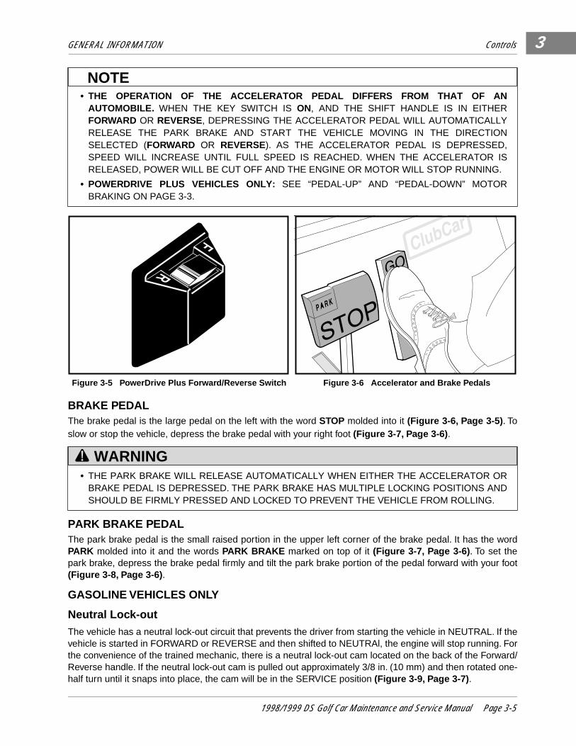
DS PowerDrive Plus With Motor BrakingThe Forward/Reverse rocker switch is located in the same place as the Forward/Reverse shift handle on allother DS models; on the seat support panel below and to the right of the driver’s right knee. The Forward (F)and Reverse (R) positions are clearly marked on the switch. Push down the F (forward) side of the switch torun the vehicle in the FORWARD direction, or push down the R (reverse) side of the switch to run the vehiclein REVERSE. When the switch is positioned with neither side down, the vehicle is in the NEUTRAL positionand the vehicle will not run if the accelerator pedal is depressed (Figure 3-5, Page 3-5) .
ACCELERATOR PEDAL
The accelerator pedal is the pedal on the right, with the word GO molded into it (Figure 3-6, Page 3-5) .
• THE KEY CAN BE REMOVED WHEN THE KEY SWITCH IS IN THE OFF POSITION ONLY.
Figure 3-3 Key Switch Figure 3-4 Forward and Reverse Handle
• THE REVERSE BUZZER WILL SOUND AS A WARNING WHEN THE VEHICLE IS IN REVERSE.
NOTE
OFF ON
NOTE
Page 3-4 1998/1999 DS Golf Car Maintenance and Service Manual
GENERAL INFORMATION Controls
3
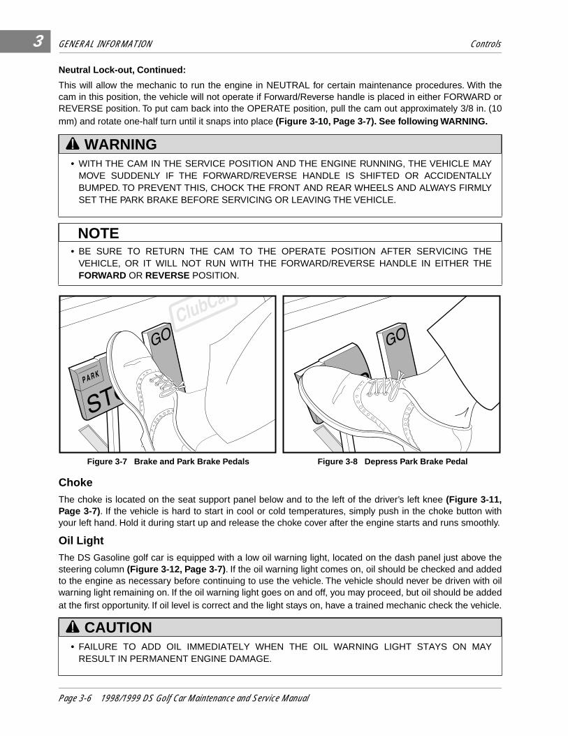
BRAKE PEDALThe brake pedal is the large pedal on the left with the word STOP molded into it (Figure 3-6, Page 3-5) . Toslow or stop the vehicle, depress the brake pedal with your right foot (Figure 3-7, Page 3-6) .
PARK BRAKE PEDALThe park brake pedal is the small raised portion in the upper left corner of the brake pedal. It has the wordPARK molded into it and the words PARK BRAKE marked on top of it (Figure 3-7, Page 3-6) . To set thepark brake, depress the brake pedal firmly and tilt the park brake portion of the pedal forward with your foot(Figure 3-8, Page 3-6) .
GASOLINE VEHICLES ONLY
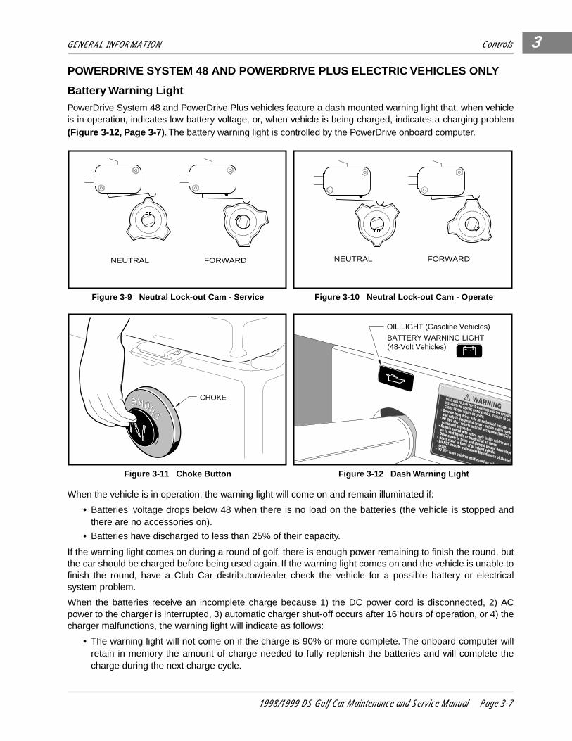
Neutral Lock-outThe vehicle has a neutral lock-out circuit that prevents the driver from starting the vehicle in NEUTRAL. If thevehicle is started in FORWARD or REVERSE and then shifted to NEUTRAl, the engine will stop running. Forthe convenience of the trained mechanic, there is a neutral lock-out cam located on the back of the Forward/Reverse handle. If the neutral lock-out cam is pulled out approximately 3/8 in. (10 mm) and then rotated one-half turn until it snaps into place, the cam will be in the SERVICE position (Figure 3-9, Page 3-7) .
• THE OPERATION OF THE ACCELERATOR PEDAL DIFFERS FROM THAT OF ANAUTOMOBILE. WHEN THE KEY SWITCH IS ON, AND THE SHIFT HANDLE IS IN EITHERFORWARD OR REVERSE, DEPRESSING THE ACCELERATOR PEDAL WILL AUTOMATICALLYRELEASE THE PARK BRAKE AND START THE VEHICLE MOVING IN THE DIRECTIONSELECTED (FORWARD OR REVERSE). AS THE ACCELERATOR PEDAL IS DEPRESSED,SPEED WILL INCREASE UNTIL FULL SPEED IS REACHED. WHEN THE ACCELERATOR ISRELEASED, POWER WILL BE CUT OFF AND THE ENGINE OR MOTOR WILL STOP RUNNING.
• POWERDRIVE PLUS VEHICLES ONLY: SEE “PEDAL-UP” AND “PEDAL-DOWN” MOTORBRAKING ON PAGE 3-3.
Figure 3-5 PowerDrive Plus Forward/Reverse Switch Figure 3-6 Accelerator and Brake Pedals
• THE PARK BRAKE WILL RELEASE AUTOMATICALLY WHEN EITHER THE ACCELERATOR ORBRAKE PEDAL IS DEPRESSED. THE PARK BRAKE HAS MULTIPLE LOCKING POSITIONS ANDSHOULD BE FIRMLY PRESSED AND LOCKED TO PREVENT THE VEHICLE FROM ROLLING.
NOTE
R
F
WARNING
1998/1999 DS Golf Car Maintenance and Service Manual Page 3-5
GENERAL INFORMATION Controls
3
Neutral Lock-out, Continued:
This will allow the mechanic to run the engine in NEUTRAL for certain maintenance procedures. With thecam in this position, the vehicle will not operate if Forward/Reverse handle is placed in either FORWARD orREVERSE position. To put cam back into the OPERATE position, pull the cam out approximately 3/8 in. (10mm) and rotate one-half turn until it snaps into place (Figure 3-10, Page 3-7). See following WARNING.
ChokeThe choke is located on the seat support panel below and to the left of the driver’s left knee (Figure 3-11,Page 3-7). If the vehicle is hard to start in cool or cold temperatures, simply push in the choke button withyour left hand. Hold it during start up and release the choke cover after the engine starts and runs smoothly.
Oil LightThe DS Gasoline golf car is equipped with a low oil warning light, located on the dash panel just above thesteering column (Figure 3-12, Page 3-7) . If the oil warning light comes on, oil should be checked and addedto the engine as necessary before continuing to use the vehicle. The vehicle should never be driven with oilwarning light remaining on. If the oil warning light goes on and off, you may proceed, but oil should be addedat the first opportunity. If oil level is correct and the light stays on, have a trained mechanic check the vehicle.
• WITH THE CAM IN THE SERVICE POSITION AND THE ENGINE RUNNING, THE VEHICLE MAYMOVE SUDDENLY IF THE FORWARD/REVERSE HANDLE IS SHIFTED OR ACCIDENTALLYBUMPED. TO PREVENT THIS, CHOCK THE FRONT AND REAR WHEELS AND ALWAYS FIRMLYSET THE PARK BRAKE BEFORE SERVICING OR LEAVING THE VEHICLE.
• BE SURE TO RETURN THE CAM TO THE OPERATE POSITION AFTER SERVICING THEVEHICLE, OR IT WILL NOT RUN WITH THE FORWARD/REVERSE HANDLE IN EITHER THEFORWARD OR REVERSE POSITION.
Figure 3-7 Brake and Park Brake Pedals Figure 3-8 Depress Park Brake Pedal
• FAILURE TO ADD OIL IMMEDIATELY WHEN THE OIL WARNING LIGHT STAYS ON MAYRESULT IN PERMANENT ENGINE DAMAGE.
WARNING
NOTE
CAUTION
Page 3-6 1998/1999 DS Golf Car Maintenance and Service Manual
GENERAL INFORMATION Controls
3
POWERDRIVE SYSTEM 48 AND POWERDRIVE PLUS ELECTRIC VEHICLES ONLY
Battery Warning LightPowerDrive System 48 and PowerDrive Plus vehicles feature a dash mounted warning light that, when vehicleis in operation, indicates low battery voltage, or, when vehicle is being charged, indicates a charging problem(Figure 3-12, Page 3-7) . The battery warning light is controlled by the PowerDrive onboard computer.
When the vehicle is in operation, the warning light will come on and remain illuminated if:
• Batteries’ voltage drops below 48 when there is no load on the batteries (the vehicle is stopped andthere are no accessories on).
• Batteries have discharged to less than 25% of their capacity.
If the warning light comes on during a round of golf, there is enough power remaining to finish the round, butthe car should be charged before being used again. If the warning light comes on and the vehicle is unable tofinish the round, have a Club Car distributor/dealer check the vehicle for a possible battery or electricalsystem problem.
When the batteries receive an incomplete charge because 1) the DC power cord is disconnected, 2) ACpower to the charger is interrupted, 3) automatic charger shut-off occurs after 16 hours of operation, or 4) thecharger malfunctions, the warning light will indicate as follows:
• The warning light will not come on if the charge is 90% or more complete. The onboard computer willretain in memory the amount of charge needed to fully replenish the batteries and will complete thecharge during the next charge cycle.
Figure 3-9 Neutral Lock-out Cam - Service Figure 3-10 Neutral Lock-out Cam - Operate
Figure 3-11 Choke Button Figure 3-12 Dash Warning Light
NEUTRAL FORWARD NEUTRAL FORWARD
CHOKE
OIL LIGHT (Gasoline Vehicles)
BATTERY WARNING LIGHT(48-Volt Vehicles) +
1998/1999 DS Golf Car Maintenance and Service Manual Page 3-7
GENERAL INFORMATION Controls3
Battery Warning Light, Continued:• When the charger is unplugged, the warning light will come on and remain illuminated for 10 seconds ifthe charge is less than 90% complete but the car has enough power to complete 36 holes of golf. Thiswill alert the fleet operator that the car may be used, but that it must be charged to completion as soonas possible.
• The warning light will repeatedly illuminate for 10 seconds, with 4 second intervals, if the charger timesout at 16 hours (see charger manual) and the batteries are not sufficiently charged. This indicates anabnormal charge cycle. Charger and batteries should be checked by your Club Car distributor/dealer.
• The warning light will repeatedly illuminate for 10 seconds, with 4 second intervals, during a chargecycle (DC plug is still connected) if AC power to the charger is interrupted. The light will go out when ACpower is restored.
POWERDRIVE PLUS ELECTRIC VEHICLES ONLY
Tow/Run Switch
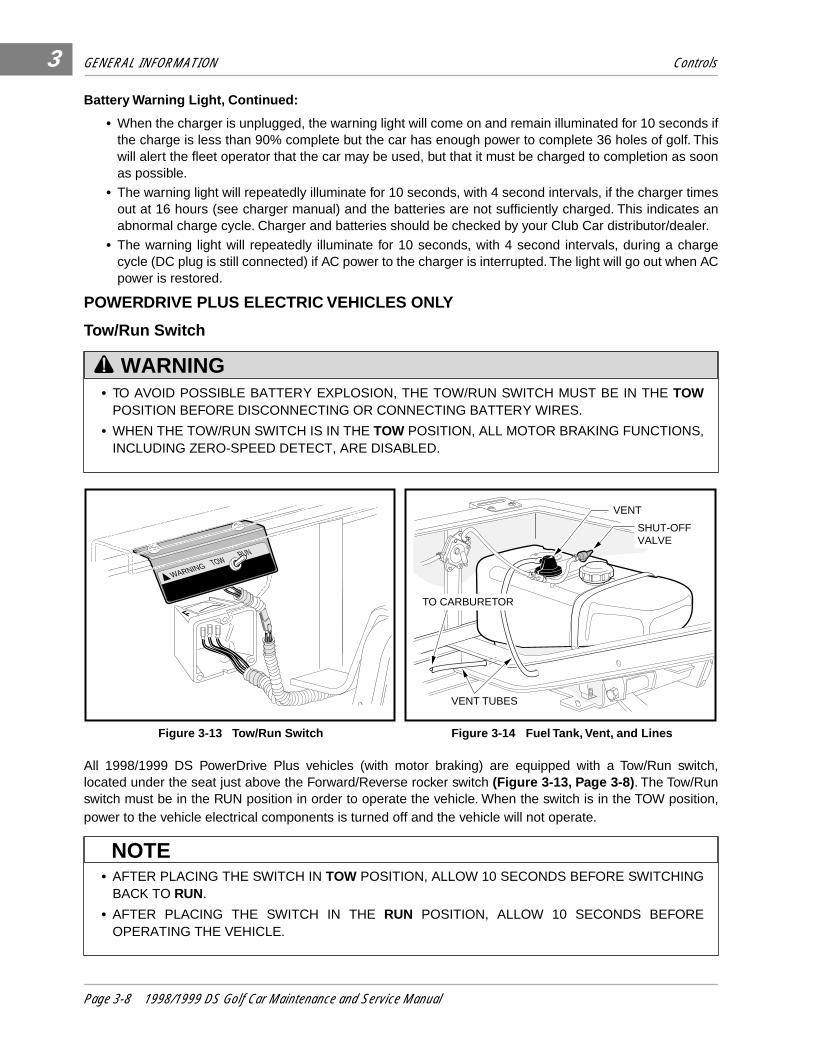
All 1998/1999 DS PowerDrive Plus vehicles (with motor braking) are equipped with a Tow/Run switch,located under the seat just above the Forward/Reverse rocker switch (Figure 3-13, Page 3-8) . The Tow/Runswitch must be in the RUN position in order to operate the vehicle. When the switch is in the TOW position,power to the vehicle electrical components is turned off and the vehicle will not operate.
• TO AVOID POSSIBLE BATTERY EXPLOSION, THE TOW/RUN SWITCH MUST BE IN THE TOWPOSITION BEFORE DISCONNECTING OR CONNECTING BATTERY WIRES.
• WHEN THE TOW/RUN SWITCH IS IN THE TOW POSITION, ALL MOTOR BRAKING FUNCTIONS,INCLUDING ZERO-SPEED DETECT, ARE DISABLED.
Figure 3-13 Tow/Run Switch Figure 3-14 Fuel Tank, Vent, and Lines
• AFTER PLACING THE SWITCH IN TOW POSITION, ALLOW 10 SECONDS BEFORE SWITCHINGBACK TO RUN.
• AFTER PLACING THE SWITCH IN THE RUN POSITION, ALLOW 10 SECONDS BEFOREOPERATING THE VEHICLE.
WARNING
F
TOWRUN
WARNING
VENT TUBES
TO CARBURETOR
SHUT-OFF VALVE
VENT
NOTE
Page 3-8 1998/1999 DS Golf Car Maintenance and Service Manual

GENERAL INFORMATION Driving Instructions 3
The Tow/Run switch should be placed in the TOW position under the following conditions:• Before Towing the Vehicle: Place the Tow/Run switch in the TOW position to disable all motor brakingfunctions, thus preventing possible damage that could occur to the vehicle or electrical components ifthe vehicle is towed while the Zero-Speed Detect motor braking function is operating.
• Before Disconnecting or Attaching Battery Wires: Place the Tow/Run switch in the TOW position toturn off power to the vehicle electrical system, thus preventing severe arcing and possible batteryexplosion as the battery wires are disconnected.
• For Long Term Storage: Place the Tow/Run switch in the TOW position to turn off power to the vehicleelectrical system, preventing vehicle electrical components from discharging the batteries.
DRIVING INSTRUCTIONS
• IF RENTING OR LOANING VEHICLE, MAKE SURE DRIVER IS FAMILIAR WITH ALL CONTROLSAND OPERATING PROCEDURES BEFORE ALLOWING THE VEHICLE TO BE DRIVEN.
• NO MORE THAN TWO PEOPLE SHOULD BE ON THE VEHICLE AT ONE TIME.
• THE VEHICLE IS NOT SPECIALLY EQUIPPED FOR HANDICAPPED PERSONS. BE SURE ALLPERSONS CAN PROPERLY OPERATE THE VEHICLE PRIOR TO ALLOWING THEM TO DRIVETHE VEHICLE.
• FOR NIGHT USE, THE VEHICLE MUST BE EQUIPPED WITH HEADLIGHTS, TAILLIGHTS, ANDREFLECTORS.
• STOP THE VEHICLE BEFORE SHIFTING THE FORWARD/REVERSE HANDLE. FAILURE TO DOSO MAY RESULT IN INJURY TO AN UNSUSPECTING PASSENGER AND (OR) DAMAGE TO THEVEHICLE. A BUZZER WILL SOUND AS A WARNING WHEN THE VEHICLE IS IN REVERSE.
WHEN DRIVING THE VEHICLE:
• OPERATE THE VEHICLE FROM THE DRIVER’S SEAT ONLY.
• TO PREVENT FALLS FROM THE VEHICLE, REMAIN SEATED IN A MOVING VEHICLE AND HOLDON TO SEAT HANDLES OR HANDRAILS AT ALL TIMES. DRIVER SHOULD KEEP BOTH HANDSON THE STEERING WHEEL WHEN THE VEHICLE IS IN MOTION.
• TO PREVENT THE POSSIBILITY OF SERIOUS INJURY, KEEP ENTIRE BODY INSIDE THEVEHICLE.
• TO PREVENT OVERTURNING THE VEHICLE, DRIVE SLOWLY IN TURNS.
• TO PREVENT OVERTURNING THE VEHICLE, DRIVE SLOWLY STRAIGHT UP AND DOWNSLOPES. DO NOT DRIVE THE VEHICLE ON SLOPES EXCEEDING 20% INCLINE.
• TO AVOID POSSIBLE INJURY TO AN UNSUSPECTING PASSENGER AND (OR) DAMAGE TO THEVEHICLE, AVOID SUDDEN STARTS, SUDDEN STOPS, AND ABRUPT TURNS.
• TO AVOID THE POSSIBILITY OF LOSING CONTROL OF OR OVERTURNING VEHICLE, REDUCESPEED FOR ADVERSE DRIVING CONDITIONS SUCH AS WET GRASS OR ROUGH TERRAIN.
• DO NOT USE THE VEHICLE ON PUBLIC ROADS. IT IS NOT DESIGNED OR INTENDED FORSTREET USE AND SHOULD NOT BE LICENSED FOR USE ON PUBLIC ROADS.
• OBEY ALL LOCAL RULES CONCERNING GOLF CARS.
• THE VEHICLE SHOULD BE DRIVEN IN ONLY SPECIFIED AREAS BY TRAINED DRIVERS.
• TO AVOID BEING STRUCK, DO NOT STAND IN FRONT OF OR BEHIND THE VEHICLE.
• DO NOT DRIVE WHILE UNDER THE INFLUENCE OF ALCOHOL, DRUGS, OR MEDICATIONS.
WARNING
1998/1999 DS Golf Car Maintenance and Service Manual Page 3-9
GENERAL INFORMATION Driving Instructions3
Driving Instructions, Continued:No one should drive the vehicle without first being instructed in the proper operation and use of the vehiclecontrols. An experienced operator should accompany each first-time driver on a test drive before allowinghim(her) to operate the vehicle alone. Only licensed drivers should be allowed to drive this vehicle.
To ensure safe operation of the vehicle, follow exactly and in order, all of the following procedures. Read andunderstand all instructions prior to driving the vehicle.
STARTING THE VEHICLE1. Read safety warnings located on dash and (or) above pedals.
2. Turn key to the ON position and be sure nothing is in your path.
3. Select direction by placing shifter in desired position (F = forward or R = reverse).
4. Depress accelerator pedal. The park brake will release automatically and the vehicle will start to move.As the accelerator pedal is depressed, speed will increase until full speed is reached.
STOPPING THE VEHICLE
To stop the vehicle, release the accelerator pedal and depress the brake pedal until the vehicle comes to acomplete stop.
PARKING AND LEAVING THE VEHICLE1. After stopping vehicle, firmly depress park brake pedal until it locks. This will prevent vehicle from rolling.
2. Turn the key switch to OFF and place the shift handle in the NEUTRAL position. Remove the key whenthe vehicle is not in use.
• VEHICLE OPERATOR MUST CONTROL SPEED WHEN GOING DOWNHILL. GASOLINE VEHICLE ONLY:
• NEVER SHIFT THE VEHICLE OUT OF FORWARD WHILE GOING DOWNHILL. IF YOU DO, YOUWILL NOT BE ABLE TO SHIFT INTO REVERSE OR BACK INTO FORWARD UNTIL STOPPED.
• DEPRESS THE BRAKE PEDAL AS NECESSARY AND PARTIALLY DEPRESS THEACCELERATOR WHEN DESCENDING A HILL. WITH THE ACCELERATOR PEDAL PARTIALLYDEPRESSED, THE GOVERNOR WILL CAUSE THE ENGINE TO ASSIST THE BRAKES INCONTROLLING DOWNHILL SPEED.
POWERDRIVE PLUS VEHICLE (WITH MOTOR BRAKING) ONLY: • “PEDAL DOWN” OR “PEDAL UP” MOTOR BRAKING MAY BE USED TO CONTROL SPEED WHEN
GOING DOWNHILL (SEE PERFORMANCE INSPECTION, PAGE 3-2) . HOWEVER, TERRAIN OROTHER CONDITIONS MAY REQUIRE THAT PEDAL BRAKING BE USED IN CONJUNCTIONWITH MOTOR BRAKING.
• DRIVING THROUGH WATER MAY AFFECT THE BRAKES. AFTER DRIVING THROUGH WATER,CHECK EFFECTIVENESS OF THE BRAKES BY GENTLY DEPRESSING THE BRAKE PEDAL. IFTHE VEHICLE DOES NOT SLOW DOWN AT THE NORMAL RATE, CONTINUE TO DEPRESS THEBRAKE PEDAL UNTIL THE BRAKES DRY OUT AND NORMAL PERFORMANCE RETURNS.
• WHEN STOPPED ON A HILL, USE THE BRAKE PEDAL TO HOLD YOUR POSITION. DO NOTUSE THE ACCELERATOR PEDAL.
WARNING
WARNING
CAUTION
Page 3-10 1998/1999 DS Golf Car Maintenance and Service Manual
GENERAL INFORMATION Towing 3
• PowerDrive Plus Vehicles (Motor Braking) Only: When the vehicle Tow/Run switch is in the RUNposition, (with the Forward/Reverse handle or key switch in any position), the “zero speed detect” func-tion will prevent the vehicle from rolling at more than 1 or 2 mph unless the accelerator is depressed.This prevents the possibility of a parked vehicle (with the park brake disengaged) rolling away too fastto be overtaken on foot. See “Zero Speed Detect” on Page 3-3 .
TOWING
All vehicles are equipped with both front and rear tow bar attaching points. A light duty tow bar is available forbreak-down towing and single vehicle towing. A heavy duty detachable tow bar and a heavy duty onboardtow bar are available for multi-vehicle towing. Observe all of the above warning statements when towing.
TRANSPORTING ON A TRAILER
If the vehicle must be transported over long distances or on public highways, it should be done on anapproved trailer. See following WARNIING:
• NEVER TOW THE VEHICLE ON PUBLIC STREETS OR HIGHWAYS.• USE ONLY APPROVED CLUB CAR TOW BARS.• TURN THE KEY SWITCH TO OFF AND PLACE THE FORWARD/REVERSE HANDLE IN NEUTRAL
BEFORE TOWING THE VEHICLE.• EXTREME CAUTION SHOULD BE USED WHEN TOWING ANY VEHICLE.• DO NOT EXCEED 5 MPH (8 KPH) TOWING SPEED.• DO NOT ALLOW PASSENGERS IN THE VEHICLES BEING TOWED.• AVOID SUDDEN STARTS, SUDDEN STOPS, AND TIGHT TURNS WHEN TOWING.• DO NOT TOW MORE THAN ONE CLUB CAR VEHICLE WITH ANOTHER CLUB CAR VEHICLE. IF
MORE THAN ONE VEHICLE MUST BE TOWED, USE AN ADEQUATELY POWERED VEHICLE(TRACTOR OR FULL SIZED TRUCK) PROPERLY FITTED, WITH A TOW HITCH HEIGHT OF 11INCHES. ONLY HEAVY-DUTY TOW BARS SHOULD BE USED FOR MULTI-VEHICLE TOWING.NEVER TOW MORE THAN FIVE VEHICLES AT ONE TIME.
• POWERDRIVE PLUS VEHICLE (WITH MOTOR BRAKING) ONLY: PLACE THE TOW/RUNSWITCH IN THE TOW POSITION. THE VEHICLE WILL NOT ROLL OTHERWISE.
• FOR USE ON PUBLIC ROADS, THE TRAILER MUST MEET ALL FEDERAL, STATE, AND LOCALREQUIREMENTS SUCH AS TAILLIGHTS, BRAKE LIGHTS, ETC.
• NEVER TOW A CLUB CAR VEHICLE BEHIND A PASSENGER VEHICLE OR TRUCK ON APUBLIC ROAD UNLESS IT IS ON AN APPROVED TRAILER.
• ALWAYS USE AN APPROVED TRAILER THAT HAS A LOAD RATING OF 1200 LB (544 KG) PERVEHICLE TO BE TOWED (EXAMPLE: A TWO-CAR TRAILER SHOULD BE RATED AT 2 X 1200 =2400 LB (2 X 544 = 1088 KG)).
• THE VEHICLE TO BE TOWED SHOULD BE TIED SECURELY TO THE TRAILER, WITH THEFORWARD/REVERSE HANDLE IN NEUTRAL , THE KEY SWITCH OFF, AND THE PARK BRAKEFIRMLY DEPRESSED AND LOCKED.
• WHEN TOWING ON A TRAILER, REDUCE NORMAL ROAD SPEED OF THE TOW VEHICLE.• BECAUSE OF ADDED LENGTH OF THE TRAILER, USE CAUTION WHEN TURNING A CORNER.• REMOVE THE VEHICLE WINDSHIELD BEFORE TRANSPORTING ON A TRAILER.• GASOLINE VEHICLE ONLY: TURN FUEL SHUT-OFF VALVE TO OFF (FIGURE 3-14, PAGE 3-8).
WARNING
WARNING
1998/1999 DS Golf Car Maintenance and Service Manual Page 3-11
GENERAL INFORMATION Storage - Gasoline Vehicle3
STORAGE - GASOLINE VEHICLE
To prepare your vehicle for extended off season storage:
1. Store vehicle in a cool place. This will prevent self-discharge of the battery. If the battery appears to beweak, have it charged using an automotive-type 12-volt battery charger rated 10 amps or less.
2. Drain carburetor.
2.1. Place the Forward/Reverse handle in the NEUTRAL position and the neutral lock-out cam in theSERVICE position. Turn the fuel shut-off valve to the CLOSED (OFF) position and run the engineuntil fuel remaining in the carburetor and fuel lines is used up and the engine stalls. Return theneutral lock-out cam to OPERATE position.
2.2. Loosen (do not remove) carburetor drain screw and drain fuel remaining in bowl into a small con-tainer, then pour fuel from the container into vehicle fuel tank. Retighten carburetor drain screw.
2.3. Disconnect fuel vent line from fuel tank vent nipple.
2.4. Plug the fuel tank vent nipple so that it is air tight. We recommend using a slip-on vinyl cap.
3. To protect the engine, remove the spark plug and pour 1/2 ounce of SAE 10 weight oil into the enginethrough the spark plug hole. Rotate the engine crankshaft several times and then re-install spark plug.
4. Increase tire pressure to 20 psi (.96 kPa).
• GASOLINE—FLAMMABLE! EXPLOSIVE! DO NOT SMOKE. KEEP SPARKS AND FLAMESAWAY FROM THE AREA OF THE VEHICLE.
• NEVER ATTEMPT TO DRAIN GASOLINE WHEN THE ENGINE IS HOT OR WHILE IT ISRUNNING. BE SURE TO CLEAN UP ANY SPILLED GASOLINE BEFORE OPERATING VEHICLE.
• STORE GASOLINE IN AN APPROVED GASOLINE CONTAINER ONLY. STORE IN A WELL-VENTILATED AREA AWAY FROM SPARKS, OPEN FLAMES, HEATERS, OR HEAT SOURCES.
• DO NOT SERVICE, REPAIR, OR OPERATE IN AN ENCLOSED AREA WITHOUT PROPERVENTILATION. THE ENGINE PRODUCES CARBON MONOXIDE WHICH IS AN ODORLESS,DEADLY POISON.
• KEEP GASOLINE OUT OF THE REACH OF CHILDREN.• DO NOT SIPHON GASOLINE FROM THE VEHICLE.
• DO NOT ATTEMPT TO CHARGE A BATTERY IF IT IS FROZEN OR IF THE CASE IS BULGED.DISCARD THE BATTERY. FROZEN BATTERIES CAN EXPLODE.
• BATTERIES IN A LOW STATE OF CHARGE WILL FREEZE AT LOW TEMPERATURES.
• TURN THE KEY SWITCH OFF, REMOVE THE KEY, AND LEAVE THE FORWARD/REVERSEHANDLE IN THE NEUTRAL POSITION DURING STORAGE. THIS IS TO PREVENTUNINTENTIONALLY STARTING THE VEHICLE.
DANGER
WARNING
CAUTION
WARNING
Page 3-12 1998/1999 DS Golf Car Maintenance and Service Manual
GENERAL INFORMATION Storage - Electric Vehicle 3
5. Grease front suspension and do all quarterly periodic lubrication. See Periodic Lubrication Sched-ule, Section 10, Maintenance and Service Supplement.
6. Thoroughly clean front body, rear body, seats, engine compartment, and underside of vehicle.
7. Do not latch the park brake. Chock wheels to prevent the vehicle from rolling.
TO RETURN THE STORED VEHICLE TO SERVICE1. Restore fuel system to operation.
1.1. Remove plug from the fuel tank vent nipple and connect the vent line to the nipple. Open fuelshut-off valve.
1.2. Place the Forward/Reverse handle in the NEUTRAL position and the neutral lock-out cam in theSERVICE position. Crank the engine until fuel is pumped into the carburetor and fuel lines andthe engine starts. Turn engine off and return neutral lock-out cam to the OPERATE position.
2. Readjust tire pressure to 12-14 psi (.57/.67 kPa).
3. Perform the Pre-Operation Checklist (see pages 3-2 and 3-3) .
STORAGE - ELECTRIC VEHICLE
1. Fully charge batteries. See Batteries, Section 13, Maintenance and Service Supplement .
2. Wash off any corrosion around the terminals with a solution of baking soda and water (one cup per gal-lon of water), then rinse solution from the batteries (do not allow this solution to enter the batteries). Letthe terminals dry and coat them with Battery Terminal Spray, Club Car Part No. 1014305.
3. Store in a cool, dry place. This will prevent self-discharge of the batteries.
• DUE TO THE OIL ADDED TO THE ENGINE IN PREPARATION FOR STORAGE, THE ENGINEMAY SMOKE EXCESSIVELY FOR A SHORT WHILE WHEN RUNNING IT FOR THE FIRST TIMEAFTER STORAGE.
• TURN THE KEY SWITCH OFF, REMOVE THE KEY, AND LEAVE THE FORWARD/REVERSEHANDLE IN THE NEUTRAL POSITION DURING STORAGE. THIS IS TO PREVENTUNINTENTIONALLY STARTING THE VEHICLE.
• POWERDRIVE PLUS VEHICLES (WITH MOTOR BRAKING) ONLY: PLACE THE TOW/RUNSWITCH IN THE TOW POSITION.
• DO NOT ATTEMPT TO CHARGE FROZEN BATTERIES OR BATTERIES WITH BULGED CASES.DISCARD THE BATTERY. FROZEN BATTERIES CAN EXPLODE.
• BATTERIES IN LOW STATE OF CHARGE WILL FREEZE AT LOW TEMPERATURES.
• WHEN WASHING THE VEHICLE, DO NOT DIRECT WATER STREAM AT THE MULTI-STEPPOTENTIOMETER (48-VOLT VEHICLES) OR V-GLIDE SPEED SWITCH (36-VOLT VEHICLE),FORWARD AND REVERSE SWITCH, OR OTHER ELECTRICAL COMPONENT.
• IF BATTERY WIRE TERMINALS ARE DAMAGED OR CORRODED, THEY SHOULD BEREPLACED OR CLEANED AS NECESSARY. FAILURE TO DO SO MAY CAUSE THEM TOOVERHEAT DURING OPERATION.
NOTE
WARNING
CAUTION
1998/1999 DS Golf Car Maintenance and Service Manual Page 3-13
GENERAL INFORMATION Storage - Electric Vehicle3
Storage - Electric Vehicle, Continued:4. Adjust tire pressure to 20 psi (.96 kPa).
5. Grease front suspension and do all quarterly periodic lubrication. See Periodic Lubrication Sched-ule, Section 10, Maintenance and Service Supplement.
6. Thoroughly clean front body, rear body, seats, battery compartment, and underside of vehicle.
7. Do not latch the park brake. Chock wheels to prevent the vehicle from rolling.
8. Keep batteries fully charged during storage. See Batteries, Section 13, Maintenance and ServiceSupplement.
• Charge 36-volt vehicles with Accu-Power battery chargers every 6-8 weeks as necessary. If it is notpossible or practical to charge the batteries, leave them disconnected while the vehicle is in storage.
• Leave PowerDrive System 48 and PowerDrive Plus vehicles with PowerDrive chargers plugged in dur-ing storage. The PowerDrive storage charge feature will automatically charge the batteries as neededthroughout storage period. If it is not possible to charge the batteries, leave the batteries disconnectedduring storage. See Batteries, Section 13, Maintenance and Service Supplement .
TO RETURN THE STORED VEHICLE TO SERVICE1. Fully charge batteries. See Batteries, Section 13, Maintenance and Service Supplement .
2. Readjust tire pressure to 18-20 psi (.86/.96 kPa).
3. Perform the Pre-Operation Checklist. See pages 3-2 and 3-3 .
• A POWERDRIVE SYSTEM 48 OR POWERDRIVE PLUS VEHICLE WILL NOT OPERATE WHILEPLUGGED TO A CHARGER.
NOTE
Page 3-14 1998/1999 DS Golf Car Maintenance and Service Manual
4
SECTION 4–BODY AND TRIM
• ONLY TRAINED MECHANICS SHOULD REPAIR OR SERVICE THIS VEHICLE. ANYONE DOINGEVEN SIMPLE REPAIRS OR SERVICE SHOULD HAVE KNOWLEDGE AND EXPERIENCE INGENERAL ELECTRICAL AND MECHANICAL REPAIR. FOLLOW ALL PROCEDURES EXACTLY.
• HEED DANGER, WARNING, AND CAUTION STATEMENTS IN THIS MANUAL, AS WELL ASMANUFACTURERS’ WARNINGS ON BODY REPAIR AND CLEANING PRODUCTS.
• ALWAYS WEAR SAFETY GLASSES OR APPROVED EYE PROTECTION WHILE SERVICING THEVEHICLE. WEAR A FULL FACE SHIELD WHEN WORKING WITH BATTERIES.
• ALWAYS WEAR A RESPIRATOR APPROVED FOR DUST AND MIST WHEN CUTTING, SANDING,PAINTING, OR REPAIRING BODY PANELS.
• DO NOT SWALLOW OR INHALE CLEANING PRODUCTS. USE IN A WELL-VENTILATED AREA.
• ALWAYS WEAR PROTECTIVE GLOVES. CLEANING PRODUCTS MAY BE HARMFUL ORIRRITATING TO SKIN.
• TURN KEY SWITCH OFF, PLACE FORWARD/REVERSE HANDLE IN THE NEUTRAL POSITION,AND REMOVE KEY BEFORE SERVICING THE VEHICLE.
• DO NOT WEAR LOOSE CLOTHING. REMOVE JEWELRY SUCH AS RINGS, WATCHES, CHAINS,ETC. WHEN SERVICING VEHICLE.
• USE INSULATED TOOLS WHEN WORKING NEAR BATTERIES OR ELECTRICAL CONNECTIONS.
• MOVING PARTS! - DO NOT ATTEMPT TO SERVICE VEHICLE WITH ENGINE/MOTOR RUNNING.
• HOT! - DO NOT ATTEMPT TO SERVICE VEHICLE WITH HOT MOTOR, RESISTORS, ENGINE,OR EXHAUST SYSTEM. FAILURE TO HEED THIS WARNING COULD RESULT IN SEVEREBURNS.
GASOLINE VEHICLE:
• TO AVOID UNINTENTIONALLY STARTING THE VEHICLE:
- DISCONNECT THE BATTERY CABLES, NEGATIVE (-) FIRST (SEE SECTION 1, FIGURE 1-1).
- DISCONNECT THE SPARK PLUG WIRE FROM THE PLUG.
• FRAME GROUND - DO NOT ALLOW TOOLS OR OTHER METAL OBJECTS TO CONTACTFRAME WHEN DISCONNECTING BATTERY CABLES OR OTHER ELECTRIC WIRING. NEVERALLOW A POSITIVE WIRE TO TOUCH THE VEHICLE FRAME, ENGINE, OR OTHER METALCOMPONENT.
ELECTRIC VEHICLE:
• TO AVOID UNINTENTIONALLY STARTING THE VEHICLE, DISCONNECT BATTERIES AS SHOWN(SECTION 1, FIGURE 1-2 OR 1-3).
• ON POWERDRIVE PLUS VEHICLES, PLACE TOW SWITCH IN THE TOW POSITION BEFOREDISCONNECTING BATTERIES.
• DISCHARGE THE CONTROLLER AS FOLLOWS AFTER DISCONNECTING BATTERIES:
- TURN THE KEY SWITCH TO ON AND PLACE THE FORWARD/REVERSE HANDLE IN THEREVERSE POSITION.
- SLOWLY DEPRESS THE ACCELERATOR PEDAL AND KEEP IT DEPRESSED UNTIL THEREVERSE WARNING BUZZER CAN NO LONGER BE HEARD. WHEN THE BUZZER STOPSSOUNDING, THE CONTROLLER IS DISCHARGED.
WARNING
1998/1999 DS Golf Car Maintenance and Service Manual Page 4-1
BODY AND TRIM General Information
4
MONOCOAT PAINT INCORPORATION DATES
GENERAL INFORMATION
Each vehicle is equipped with an injection molded Armorflex® front and rear body. Use a mild soap or deter-gent with a sponge or soft cloth for normal cleaning. Battery acid, fertilizers, tars, asphalt, creosote, paint, orchewing gum should be removed immediately to prevent possible stains. Because the finish on the vehicle isthe same as the finish on today’s automobiles, commercial automotive cleaning products should be used.
FRONT AND REAR BODY REPAIR
STRESS LINES OR STREAKSRepeated flexing of the body can cause white stress lines or streaks to appear. To remove them:
• DO NOT USE DETERGENTS OR CLEANING SOLVENTS THAT CONTAIN AMMONIA, AROMATICSOLVENTS, OR ALKALI MATERIALS ON BODY PANELS OR SEATS.
• DO NOT ALLOW BATTERY ACID TO DRIP ON BODY PANELS. BATTERY ACID WILL CAUSEPERMANENT BLEMISHES. WASH ACID OFF BODY PANELS IMMEDIATELY.
• DO NOT ALLOW CLEANING PRODUCTS TO CONTACT CLOTHES OR VEHICLE SURFACESOTHER THAN THOSE FOR WHICH CLEANING PRODUCTS ARE INTENDED.
• THE INFORMATION IN THIS SECTION APPLIES TO ONLY THOSE 1999 VEHICLES WITH THEMATCHED PAINT OVER PRIMER MONOCOAT FINISH. SEE NOTE BELOW.
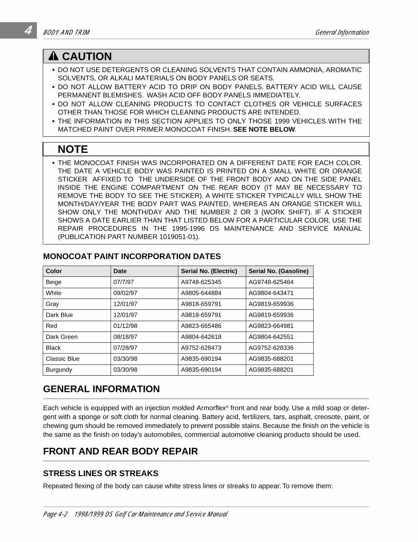
• THE MONOCOAT FINISH WAS INCORPORATED ON A DIFFERENT DATE FOR EACH COLOR.THE DATE A VEHICLE BODY WAS PAINTED IS PRINTED ON A SMALL WHITE OR ORANGESTICKER AFFIXED TO THE UNDERSIDE OF THE FRONT BODY AND ON THE SIDE PANELINSIDE THE ENGINE COMPARTMENT ON THE REAR BODY (IT MAY BE NECESSARY TOREMOVE THE BODY TO SEE THE STICKER). A WHITE STICKER TYPICALLY WILL SHOW THEMONTH/DAY/YEAR THE BODY PART WAS PAINTED, WHEREAS AN ORANGE STICKER WILLSHOW ONLY THE MONTH/DAY AND THE NUMBER 2 OR 3 (WORK SHIFT). IF A STICKERSHOWS A DATE EARLIER THAN THAT LISTED BELOW FOR A PARTICULAR COLOR, USE THEREPAIR PROCEDURES IN THE 1995-1996 DS MAINTENANCE AND SERVICE MANUAL(PUBLICATION PART NUMBER 1019051-01).
Color Date Serial No. (Electric) Serial No. (Gasoline)
Beige 07/7/97 A9748-625345 AG9748-625464
White 09/02/97 A9805-644884 AG9804-643471
Gray 12/01/97 A9818-659791 AG9819-659936
Dark Blue 12/01/97 A9818-659791 AG9819-659936
Red 01/12/98 A9823-665486 AG9823-664981
Dark Green 08/18/97 A9804-642618 AG9804-642551
Black 07/28/97 A9752-628473 AG9752-628336
Classic Blue 03/30/98 A9835-690194 AG9835-688201
Burgundy 03/30/98 A9835-690194 AG9835-688201
CAUTION
NOTE
Page 4-2 1998/1999 DS Golf Car Maintenance and Service Manual
BODY AND TRIM Front and Rear Body Repair
4
1. Hold a heat gun 12 in. (30 cm) away from the affected area, with the gun on its lowest heat setting.
2. Slowly wave the heat gun back and forth over the affected area until the streak fades.
3. It may be necessary to move the gun closer to the body to fade the streak, but under no circumstancesshould the gun be held closer than 6 in. (15 cm) to the body.
DEFORMATION Deformations in the body can be repaired using a procedure similar to the one used to remove stress lines.To remove deformations:
1. Hold a heat gun 12 in. (30 cm) away from the affected area, with the gun on its lowest heat setting.
2. Periodically remove the heat gun and bend the body in the opposite direction of the deformation.
3. Continue heating and bending the body until the original shape returns. Under no circumstancesshould the gun be held closer than 6 in. (15 cm) to the body.
MINOR SCRATCHES AND SURFACE BLEMISHES1. Thoroughly clean the affected area using strong, non-abrasive detergent and hot water, then clean with
Ultra-Kleen® Solvent Cleaner to remove any oil based contaminants.
2. Lightly buff imperfection with a clean, soft cloth or buff pad. Do not use any kind of polishing compound.
3. Wax the entire body part to restore luster and weather protection.
SMALL SCRATCHES THAT CANNOT BE BUFFED OUT
1. Thoroughly clean the affected area with alcohol and then dry thoroughly.
2. Using 240 grit or finer sandpaper, lightly sand the scratch to feather the edges. Finish sand the scratchwith 320 grit or finer paper to remove gloss from the surface. Sand as little body surface as possiblebeyond the scratch.
3. Using the brush in the bottle cap of the touch-up paint (available from Club Car Service Parts, see colorchart at top of page 4-4), apply paint to the scratch. Multiple layers of paint may be required to fill thescratch.
4. Allow paint to dry completely, then lightly buff the imperfection.
5. Wax the entire body part to restore luster and weather protection.
6. If the TPO body material is exposed, apply a light coat of adhesion promoter (Club Car Part No.101978901) to only the bare body material.
7. Fill the scratch with body filler (Club Car Part No. 1017295). Allow the filler to dry and then sand lightly.
8. Apply primer to the filled and promoter covered area. Allow the primer to dry, then perform steps 3through 5 above.
• HOLDING THE HEAT GUN TOO CLOSE TO THE BODY COULD MELT THE BODY OR DAMAGETHE FINISH SURFACE.
• BE CAREFUL NOT TO SAND COMPLETELY THROUGH FINISH TO THE BODY MATERIAL. IFTHE FINISH IS SANDED THROUGH AND THE TPO BODY MATERIAL EXPOSED, PROCEED TOSTEP 6.
CAUTION
CAUTION
1998/1999 DS Golf Car Maintenance and Service Manual Page 4-3
BODY AND TRIM Seat
4
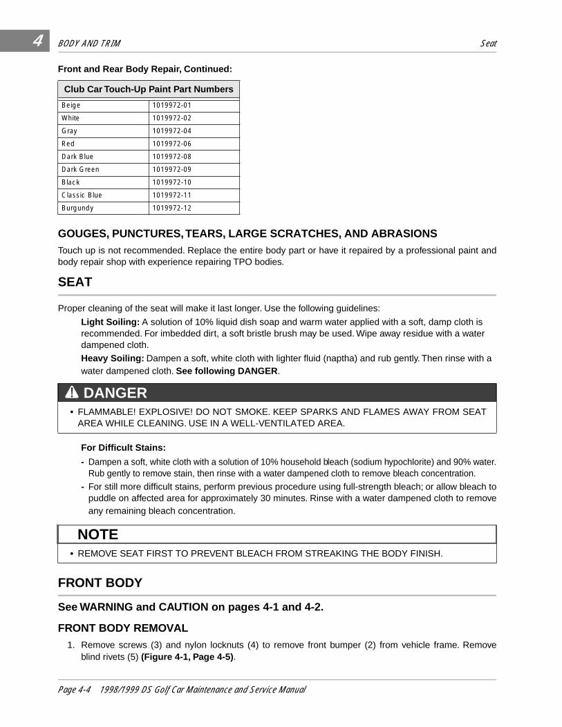
Front and Rear Body Repair, Continued:
GOUGES, PUNCTURES, TEARS, LARGE SCRATCHES, AND ABRASIONSTouch up is not recommended. Replace the entire body part or have it repaired by a professional paint andbody repair shop with experience repairing TPO bodies.
SEAT
Proper cleaning of the seat will make it last longer. Use the following guidelines:
Light Soiling: A solution of 10% liquid dish soap and warm water applied with a soft, damp cloth is recommended. For imbedded dirt, a soft bristle brush may be used. Wipe away residue with a water dampened cloth.
Heavy Soiling: Dampen a soft, white cloth with lighter fluid (naptha) and rub gently. Then rinse with a water dampened cloth. See following DANGER .
For Difficult Stains:
- Dampen a soft, white cloth with a solution of 10% household bleach (sodium hypochlorite) and 90% water.Rub gently to remove stain, then rinse with a water dampened cloth to remove bleach concentration.
- For still more difficult stains, perform previous procedure using full-strength bleach; or allow bleach topuddle on affected area for approximately 30 minutes. Rinse with a water dampened cloth to removeany remaining bleach concentration.
FRONT BODY
See WARNING and CAUTION on pages 4-1 and 4-2.
FRONT BODY REMOVAL 1. Remove screws (3) and nylon locknuts (4) to remove front bumper (2) from vehicle frame. Remove
blind rivets (5) (Figure 4-1, Page 4-5) .
Club Car Touch-Up Paint Part Numbers
Beige 1019972-01
White 1019972-02
Gray 1019972-04
Red 1019972-06
Dark Blue 1019972-08
Dark Green 1019972-09
Black 1019972-10
Classic Blue 1019972-11
Burgundy 1019972-12
• FLAMMABLE! EXPLOSIVE! DO NOT SMOKE. KEEP SPARKS AND FLAMES AWAY FROM SEATAREA WHILE CLEANING. USE IN A WELL-VENTILATED AREA.
• REMOVE SEAT FIRST TO PREVENT BLEACH FROM STREAKING THE BODY FINISH.
DANGER
NOTE
Page 4-4 1998/1999 DS Golf Car Maintenance and Service Manual
BODY AND TRIM Front Body
4
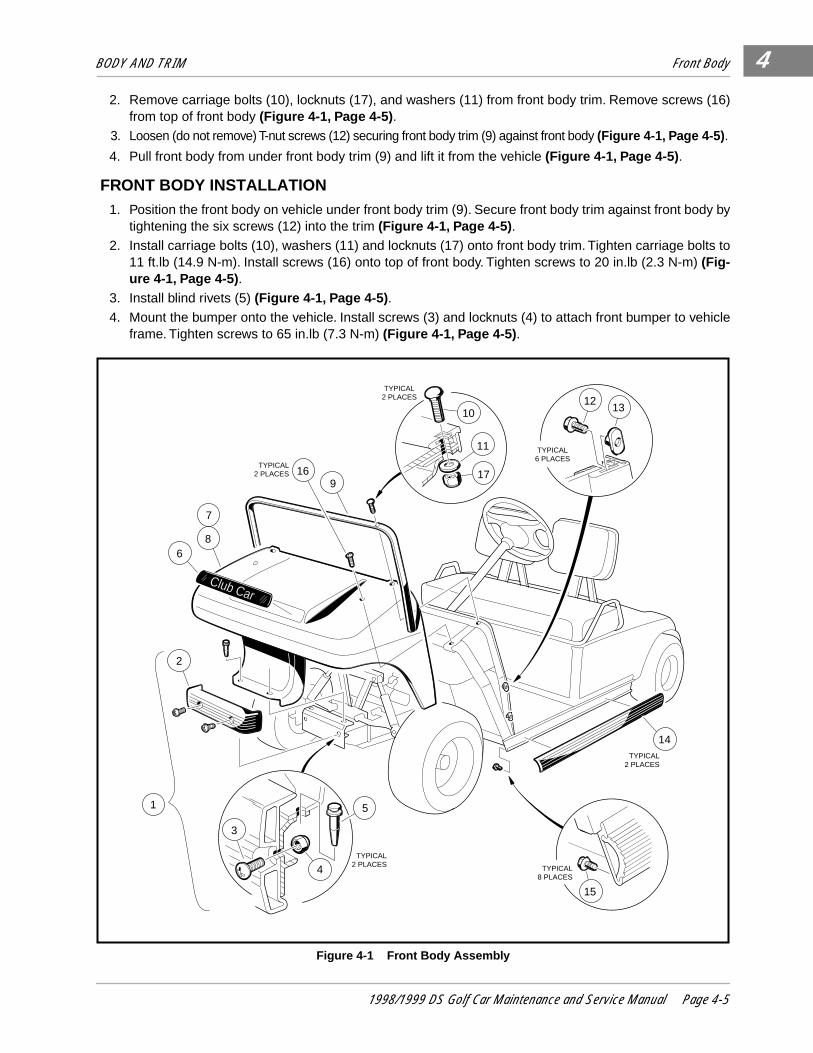
2. Remove carriage bolts (10), locknuts (17), and washers (11) from front body trim. Remove screws (16)from top of front body (Figure 4-1, Page 4-5) .
3. Loosen (do not remove) T-nut screws (12) securing front body trim (9) against front body (Figure 4-1, Page 4-5) .
4. Pull front body from under front body trim (9) and lift it from the vehicle (Figure 4-1, Page 4-5) .
FRONT BODY INSTALLATION1. Position the front body on vehicle under front body trim (9). Secure front body trim against front body by
tightening the six screws (12) into the trim (Figure 4-1, Page 4-5) .
2. Install carriage bolts (10), washers (11) and locknuts (17) onto front body trim. Tighten carriage bolts to11 ft.lb (14.9 N-m). Install screws (16) onto top of front body. Tighten screws to 20 in.lb (2.3 N-m) (Fig-ure 4-1, Page 4-5) .
3. Install blind rivets (5) (Figure 4-1, Page 4-5) .
4. Mount the bumper onto the vehicle. Install screws (3) and locknuts (4) to attach front bumper to vehicleframe. Tighten screws to 65 in.lb (7.3 N-m) (Figure 4-1, Page 4-5) .
Figure 4-1 Front Body Assembly
Club Car
14
1
2
68
7
169
10
11
17
TYPICAL2 PLACES
TYPICAL2 PLACES
TYPICAL2 PLACES
1213
TYPICAL6 PLACES
15
TYPICAL8 PLACES
5
3
4TYPICAL
2 PLACES
1998/1999 DS Golf Car Maintenance and Service Manual Page 4-5

BODY AND TRIM Rear Body
4
REAR BODY
See WARNING and CAUTION on pages 4-1 and 4-2.
REAR BODY REMOVAL
1. Remove the seat from the rear body.
2. Remove two screws (1) and locknuts located under bagwell protector in bagwell floor (Figure 4-2,Page 4-6).
3. Remove two screws located at the bottom edge of the seat support panel (in kick-plate below the For-ward/Reverse handle and just above the floormat) (Figure 4-3, Page 4-6) .
4. V-Glide Electric, PowerDrive System 48 Electric, and Gasoline vehicles - Remove the screwsecuring the Forward/Reverse handle and slide the handle from the shaft.
5. Electric vehicles only - Disconnect or remove charger receptacle:
• REAR BUMPER DOES NOT HAVE TO BE REMOVED TO REMOVE REAR BODY.
Figure 4-2 Remove Screws Under Bagwell Protector Figure 4-3 Remove Kick-Plate Screws
Figure 4-4 PowerDrive Charger Receptacle Figure 4-5 V-Glide Charger Receptacle
NOTE
1
���������������
���������������
���������������
���������������
yyyyyyyyyyyyyyy
zzzzzzzzzzzzzzz
{{{{{{{{{{{{{{{
|||||||||||||||
F
- -NR
GRAY SENSE LEADWITH FUSE
GRAY WIREFROM OBC
10 GAUGE BLACKWIRE TO OBC
10 GAUGERED WIRETO BATTERY
CHARGERRECEPTACLE
CHARGERRECEPTACLE
2
1
Page 4-6 1998/1999 DS Golf Car Maintenance and Service Manual
BODY AND TRIM Rear Body
4
• PowerDrive System 48 and PowerDrive Plus vehicles (Figure 4-4, Page 4-6):The charger receptacle must be disconnected, but does not have to be removed from the body:
5.1. Remove wire tie binding 10 gauge red wire (from charger receptacle to battery) to Forward/Reverse switch wires. Disconnect the 10 gauge red wire at the positive post of battery No. 1.
5.2. Remove the retaining nut and disconnect the 10 gauge black wire (from the on-board computer)from the receptacle.
5.3. Unplug the fuse holder assembly to disconnect the gray sense lead from the receptacle.
• V-Glide 36-volt vehicles (Figure 4-5, Page 4-6):
5.1. Remove the four phillips head screws (1) that secure the receptacle bezel (2) to the rear body.
5.2. Remove the bezel from the receptacle and then remove the receptacle from the body. The wiresdo not have to be disconnected from the receptacle.
6. Disconnect and remove Forward/Reverse Switch:
• V-Glide 36-volt and PowerDrive System 48 vehicles:
6.1. Remove three screws and nylon locknuts securing the Forward/Reverse switch to the rear body,then pull the Forward/Reverse switch from the body and place it on the vehicle frame I-beam (withwiring intact).
• PowerDrive Plus vehicles only:
6.1. Remove the three wires from the back of the Forward/Reverse switch housing by removing thethree self-tapping mounting screws.
• Gasoline vehicles only:
6.1. Remove four screws and nylon locknuts securing the Forward/Reverse shifter to the rear body.Pull the Forward/Reverse shifter from body and place it on vehicle frame I-beam.
6.2. Remove the shifter cable from the cable hanger under the driver side seat hinge.
6.3. Remove two carriage bolts and locknuts from fuel pump and remove fuel pump from seat support.
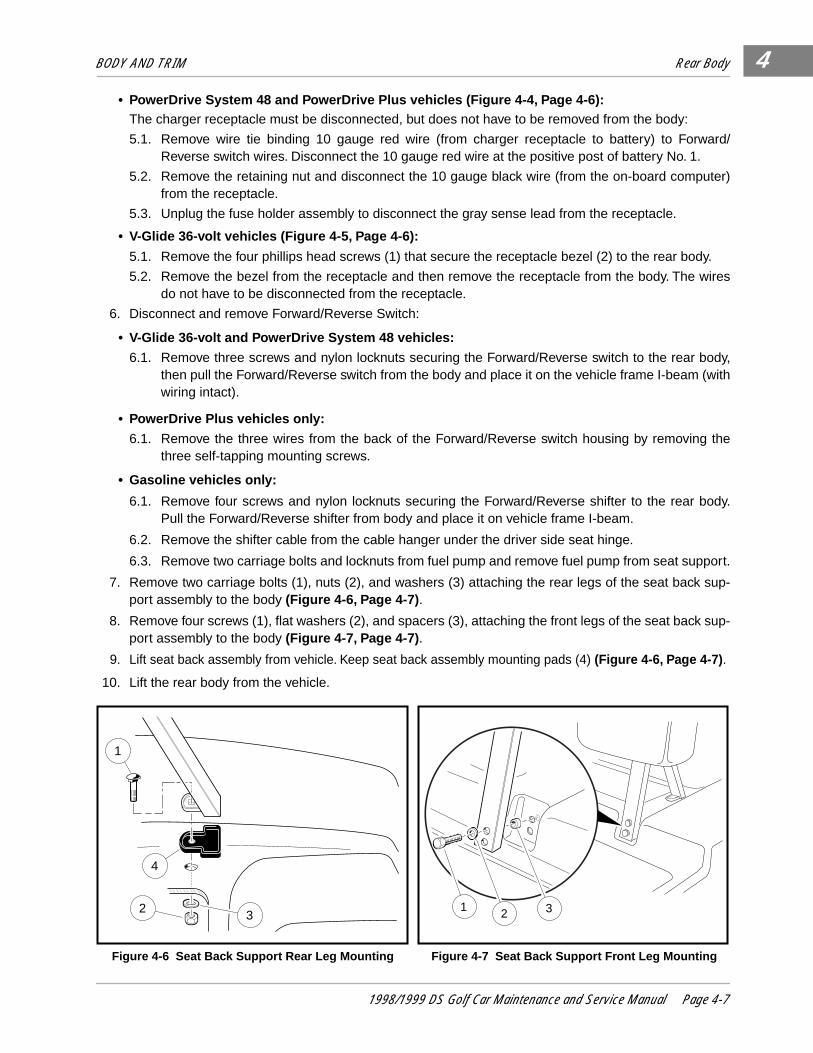
7. Remove two carriage bolts (1), nuts (2), and washers (3) attaching the rear legs of the seat back sup-port assembly to the body (Figure 4-6, Page 4-7) .
8. Remove four screws (1), flat washers (2), and spacers (3), attaching the front legs of the seat back sup-port assembly to the body (Figure 4-7, Page 4-7) .
9. Lift seat back assembly from vehicle. Keep seat back assembly mounting pads (4) (Figure 4-6, Page 4-7) .
10. Lift the rear body from the vehicle.
Figure 4-6 Seat Back Support Rear Leg Mounting Figure 4-7 Seat Back Support Front Leg Mounting
1
4
32 1 2 3
1998/1999 DS Golf Car Maintenance and Service Manual Page 4-7
BODY AND TRIM Floormat
4
REAR BODY INSTALLATION1. Install two screws in kick-plate. Tighten to 20 in.lb (2.3 N-m) (Figure 4-3, Page 4-6) .
2. Tighten two screws (1) and locknuts located under bagwell protector in bagwell floor to 20 in.lb (2.3 N-m)(Figure 4-2, Page 4-6) .
3. Tighten two carriage bolts (1), nuts (2), and washers (3) attaching the rear legs of the seat back sup-port assembly to the body to 11 ft. lb (14.9 N-m) (Figure 4-6, Page 4-7) .
4. Tighten four screws (1), flat washers (2), and spacers (3) attaching the front legs of the seat back sup-port assembly to the body to 20 in.lb (2.3 N-m) (Figure 4-7, Page 4-7) .
5. Adjust choke positioner. See Section 14–Fuel System, in the FE 290 Gasoline Vehicle Supplement.
FLOORMAT
FLOORMAT REMOVAL1. Remove the brake and accelerator pedals. See Section 5–Accelerator and Brake Pedal Group .
2. Loosen two screws in the rear body kick-plate (Figure 4-3, Page 4-6) and pull the rear edge of thefloormat from between the rear body and the floor panel.
3. Remove the top edge of the floormat from the overlapping flange under the dash.
4. Lift the mat from the vehicle.
FLOORMAT INSTALLATION1. Install the brake and accelerator pedals. See Section 5–Accelerator and Brake Pedal Group .
2. Reverse the removal procedure to install the floormat. Tighten screws to 20 in.lb (2.3 N-m).
• INSTALL THE MOUNTING PADS (4) (FIGURE 4-6, PAGE 4-7) BETWEEN THE REAR BODY ANDTHE SEAT BACK ASSEMBLY.
NOTE
Page 4-8 1998/1999 DS Golf Car Maintenance and Service Manual
5
SECTION 5–ACCELERATOR AND BRAKE PEDAL GROUP
GENERAL INFORMATION
• ONLY TRAINED MECHANICS SHOULD REPAIR OR SERVICE THE VEHICLE. ANYONE DOINGEVEN SIMPLE REPAIRS OR SERVICE SHOULD HAVE KNOWLEDGE AND EXPERIENCE INELECTRICAL AND MECHANICAL REPAIR.
• FOLLOW THE PROCEDURES EXACTLY AS STATED IN THIS MANUAL, AND HEED DANGER,WARNING, AND CAUTION STATEMENTS LISTED IN THIS MANUAL AS WELL AS THOSEAFFIXED TO THE VEHICLE.
• IMPROPER USE OF THE VEHICLE OR FAILURE TO PROPERLY MAINTAIN IT, COULD RESULTIN DECREASED VEHICLE PERFORMANCE OR SEVERE PERSONAL INJURY.
• ANY MODIFICATION OR CHANGE TO THE VEHICLE WHICH AFFECTS THE STABILITY ORHANDLING OF THE VEHICLE, OR INCREASES MAXIMUM VEHICLE SPEED BEYOND FACTORYSPECIFICATIONS, COULD RESULT IN SEVERE PERSONAL INJURY OR DEATH.
• ALWAYS WEAR SAFETY GLASSES OR APPROVED EYE PROTECTION WHEN SERVICING THEVEHICLE. WEAR A FULL FACE SHIELD WHEN WORKING WITH BATTERIES.
• DO NOT WEAR LOOSE CLOTHING. REMOVE JEWELRY SUCH AS RINGS, WATCHES, CHAINS,ETC. BEFORE SERVICING VEHICLE.
• MOVING PARTS! DO NOT ATTEMPT TO SERVICE THE VEHICLE WHILE IT IS RUNNING.
• HOT! DO NOT ATTEMPT TO SERVICE HOT MOTOR, RESISTORS, ENGINE, OR EXHAUSTSYSTEMS. FAILURE TO HEED THIS WARNING COULD RESULT IN SEVERE BURNS.
• ALWAYS USE INSULATED TOOLS WHEN WORKING AROUND BATTERIES OR ELECTRICALCONNECTIONS.
• LIFT ONLY ONE END OF VEHICLE AT A TIME. BEFORE LIFTING, LOCK THE BRAKES ANDCHOCK THE WHEELS THAT REMAIN ON THE FLOOR. USE A SUITABLE LIFTING DEVICE(CHAIN HOIST OR HYDRAULIC FLOOR JACK) WITH 1000 LBS. (454 KG.) MINIMUM LIFTINGCAPACITY. DO NOT USE LIFTING DEVICE TO HOLD VEHICLE IN RAISED POSITION. ALWAYSUSE APPROVED JACKSTANDS OF PROPER WEIGHT CAPACITY TO SUPPORT VEHICLE.
• TURN THE KEY SWITCH TO OFF, REMOVE THE KEY, CHOCK THE WHEELS, PLACE THEFORWARD/REVERSE HANDLE IN NEUTRAL , AND DISCONNECT BATTERY(IES) PRIOR TOSERVICING THE VEHICLE.
GASOLINE VEHICLES ONLY:
• TO AVOID UNINTENTIONALLY STARTING THE VEHICLE:
- DISCONNECT BATTERY CABLES, NEGATIVE (-) FIRST (FIGURE 1-1, PAGE 1-3).
- DISCONNECT THE SPARK PLUG WIRE FROM THE SPARK PLUG.
• FRAME GROUND - DO NOT ALLOW TOOLS OR OTHER METAL OBJECTS TO CONTACTFRAME WHEN DISCONNECTING BATTERY CABLES OR OTHER ELECTRIC WIRING. NEVERALLOW A POSITIVE WIRE TO TOUCH THE VEHICLE FRAME, ENGINE, OR OTHER METALCOMPONENT.
WARNING CONTINUED ON NEXT PAGE.
WARNING
1998/1999 DS Golf Car Maintenance and Service Manual Page 5-1
ACCELERATOR AND BRAKE PEDAL GROUP Pedal Group Adjustment
5
���
��zzz
||
PEDAL GROUP ADJUSTMENT
Read WARNING on page 5-1 and 5-2.1. ADJUST BRAKE PEDAL HEIGHT
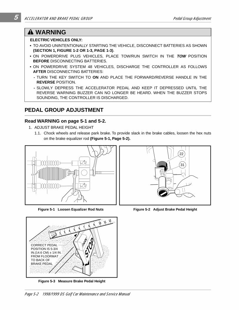
1.1. Chock wheels and release park brake. To provide slack in the brake cables, loosen the hex nutson the brake equalizer rod (Figure 5-1, Page 5-2).
ELECTRIC VEHICLES ONLY:• TO AVOID UNINTENTIONALLY STARTING THE VEHICLE, DISCONNECT BATTERIES AS SHOWN
(SECTION 1, FIGURE 1-2 OR 1-3, PAGE 1-3). • ON POWERDRIVE PLUS VEHICLES, PLACE TOW/RUN SWITCH IN THE TOW POSITION
BEFORE DISCONNECTING BATTERIES.
• ON POWERDRIVE SYSTEM 48 VEHICLES, DISCHARGE THE CONTROLLER AS FOLLOWSAFTER DISCONNECTING BATTERIES:
- TURN THE KEY SWITCH TO ON AND PLACE THE FORWARD/REVERSE HANDLE IN THEREVERSE POSITION.
- SLOWLY DEPRESS THE ACCELERATOR PEDAL AND KEEP IT DEPRESSED UNTIL THEREVERSE WARNING BUZZER CAN NO LONGER BE HEARD. WHEN THE BUZZER STOPSSOUNDING, THE CONTROLLER IS DISCHARGED.
Figure 5-1 Loosen Equalizer Rod Nuts Figure 5-2 Adjust Brake Pedal Height
Figure 5-3 Measure Brake Pedal Height
WARNING
22
31
������������
���������
��������������yyyyyyyyyyyy
zzzzzzzzz
{{{{{{{{||||||PARK
STOP
1 2 3 4 5 6 7 8 9 10 11 12
��yzCORRECT PEDAL POSITION IS 5-3/4 IN.(14.6 CM) ± 1/4 IN.FROM FLOORMATTO BACK OF BRAKE PEDAL
Page 5-2 1998/1999 DS Golf Car Maintenance and Service Manual
ACCELERATOR AND BRAKE PEDAL GROUP Pedal Group Adjustment
5
1.2. Loosen the brake stop jam nut (31), then relieve pedal pressure on the stop by pushing downslightly on the pedal. Then adjust the brake stop bumper (22) up or down (Figure 5-2, Page 5-2) .Adjusting the bumper upward decreases distance between pedal and floorboard. Adjusting thebumper downward increases distance between pedal and floorboard. Proper brake pedal heightis 5-3/4 in. (14.6 cm) ± 1/4 in (.6 cm) (Figure 5-3, Page 5-2) .
1.3. Tighten the jam nut (31) to 8 ft.lb. (9.5 N-m) (Figure 5-2, Page 5-2) .
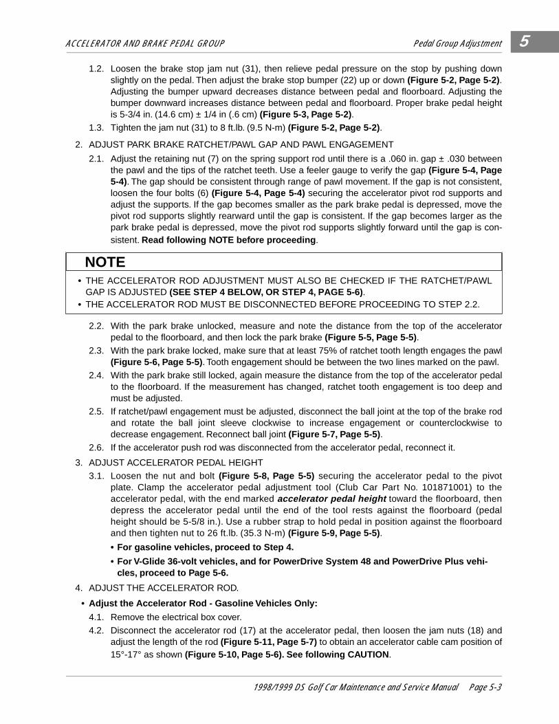
2. ADJUST PARK BRAKE RATCHET/PAWL GAP AND PAWL ENGAGEMENT
2.1. Adjust the retaining nut (7) on the spring support rod until there is a .060 in. gap ± .030 betweenthe pawl and the tips of the ratchet teeth. Use a feeler gauge to verify the gap (Figure 5-4, Page5-4). The gap should be consistent through range of pawl movement. If the gap is not consistent,loosen the four bolts (6) (Figure 5-4, Page 5-4) securing the accelerator pivot rod supports andadjust the supports. If the gap becomes smaller as the park brake pedal is depressed, move thepivot rod supports slightly rearward until the gap is consistent. If the gap becomes larger as thepark brake pedal is depressed, move the pivot rod supports slightly forward until the gap is con-sistent. Read following NOTE before proceeding .
2.2. With the park brake unlocked, measure and note the distance from the top of the acceleratorpedal to the floorboard, and then lock the park brake (Figure 5-5, Page 5-5) .
2.3. With the park brake locked, make sure that at least 75% of ratchet tooth length engages the pawl(Figure 5-6, Page 5-5) . Tooth engagement should be between the two lines marked on the pawl.
2.4. With the park brake still locked, again measure the distance from the top of the accelerator pedalto the floorboard. If the measurement has changed, ratchet tooth engagement is too deep andmust be adjusted.
2.5. If ratchet/pawl engagement must be adjusted, disconnect the ball joint at the top of the brake rodand rotate the ball joint sleeve clockwise to increase engagement or counterclockwise todecrease engagement. Reconnect ball joint (Figure 5-7, Page 5-5) .
2.6. If the accelerator push rod was disconnected from the accelerator pedal, reconnect it.
3. ADJUST ACCELERATOR PEDAL HEIGHT
3.1. Loosen the nut and bolt (Figure 5-8, Page 5-5) securing the accelerator pedal to the pivotplate. Clamp the accelerator pedal adjustment tool (Club Car Part No. 101871001) to theaccelerator pedal, with the end marked accelerator pedal height toward the floorboard, thendepress the accelerator pedal until the end of the tool rests against the floorboard (pedalheight should be 5-5/8 in.). Use a rubber strap to hold pedal in position against the floorboardand then tighten nut to 26 ft.lb. (35.3 N-m) (Figure 5-9, Page 5-5) .
• For gasoline vehicles, proceed to Step 4.
• For V-Glide 36-volt vehicles, and for PowerDrive System 48 and PowerDrive Plus vehi-cles, proceed to Page 5-6.
4. ADJUST THE ACCELERATOR ROD.
• Adjust the Accelerator Rod - Gasoline Vehicles Only: 4.1. Remove the electrical box cover.
4.2. Disconnect the accelerator rod (17) at the accelerator pedal, then loosen the jam nuts (18) andadjust the length of the rod (Figure 5-11, Page 5-7) to obtain an accelerator cable cam position of15°-17° as shown (Figure 5-10, Page 5-6). See following CAUTION .
• THE ACCELERATOR ROD ADJUSTMENT MUST ALSO BE CHECKED IF THE RATCHET/PAWLGAP IS ADJUSTED (SEE STEP 4 BELOW, OR STEP 4, PAGE 5-6) .
• THE ACCELERATOR ROD MUST BE DISCONNECTED BEFORE PROCEEDING TO STEP 2.2.
NOTE
1998/1999 DS Golf Car Maintenance and Service Manual Page 5-3
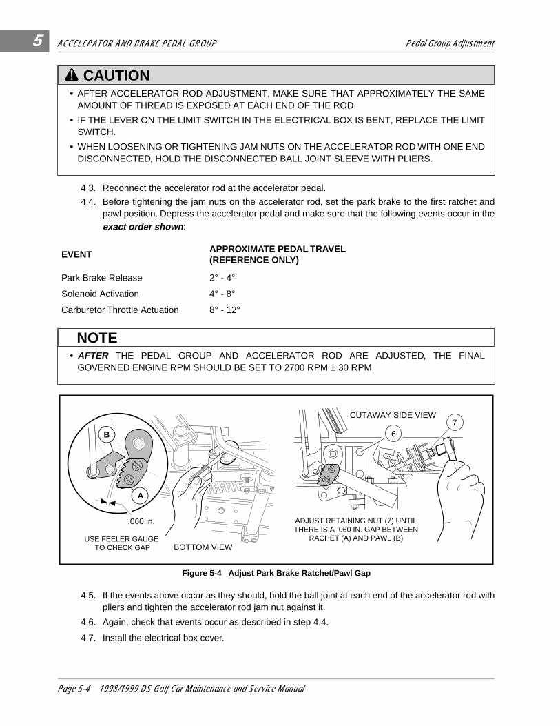
ACCELERATOR AND BRAKE PEDAL GROUP Pedal Group Adjustment
5
4.3. Reconnect the accelerator rod at the accelerator pedal.
4.4. Before tightening the jam nuts on the accelerator rod, set the park brake to the first ratchet andpawl position. Depress the accelerator pedal and make sure that the following events occur in theexact order shown :
4.5. If the events above occur as they should, hold the ball joint at each end of the accelerator rod withpliers and tighten the accelerator rod jam nut against it.
4.6. Again, check that events occur as described in step 4.4.
4.7. Install the electrical box cover.
• AFTER ACCELERATOR ROD ADJUSTMENT, MAKE SURE THAT APPROXIMATELY THE SAMEAMOUNT OF THREAD IS EXPOSED AT EACH END OF THE ROD.
• IF THE LEVER ON THE LIMIT SWITCH IN THE ELECTRICAL BOX IS BENT, REPLACE THE LIMITSWITCH.
• WHEN LOOSENING OR TIGHTENING JAM NUTS ON THE ACCELERATOR ROD WITH ONE ENDDISCONNECTED, HOLD THE DISCONNECTED BALL JOINT SLEEVE WITH PLIERS.
EVENTAPPROXIMATE PEDAL TRAVEL(REFERENCE ONLY)
Park Brake Release 2° - 4°
Solenoid Activation 4° - 8°
Carburetor Throttle Actuation 8° - 12°
• AFTER THE PEDAL GROUP AND ACCELERATOR ROD ARE ADJUSTED, THE FINALGOVERNED ENGINE RPM SHOULD BE SET TO 2700 RPM ± 30 RPM.
Figure 5-4 Adjust Park Brake Ratchet/Pawl Gap
CAUTION
NOTE
CUTAWAY SIDE VIEW
ADJUST RETAINING NUT (7) UNTILTHERE IS A .060 IN. GAP BETWEEN
RACHET (A) AND PAWL (B)
.060 in.
BOTTOM VIEW
A
B
USE FEELER GAUGE TO CHECK GAP
76
Page 5-4 1998/1999 DS Golf Car Maintenance and Service Manual

ACCELERATOR AND BRAKE PEDAL GROUP Pedal Group Adjustment
5
���
���
����
����
yyy
zzz
{{{{
||||
��
���zz
|||
Figure 5-5 Measure Accelerator Pedal Height Figure 5-6 Ratchet/Pawl Tooth Engagement
Figure 5-7 Brake Rod Adjustment Figure 5-8 Accelerator Pedal Height Adjustment
Figure 5-9 Accelerator Pedal Height Adjustment
������������
������������
����������������
����������������
yyyyyyyyyyyy
zzzzzzzzzzzz
{{{{{{{{{{{{{{{{
||||||||||||||||
�{
PARK
STOP
GOWITH PARK BRAKE
UNLOCKED MEASURE FROMFLOOR BOARD TO BACK
OF ACCELERATOR
1 2 3 4 5 6 7 8 910
RATCHET (B) TOOTH LENGTH
LOCKEDPOSITION A
B
MAKE SUREPAWL (A) ENGAGES AT LEAST 75%
OF RACHET TOOTH LENGTH (B)
ROTATE BALL JOINT (11) CLOCKWISE TO INCREASE PAWL TO RACHET ENGAGEMENT, COUNTERCLOCKWISE TO DECREASE IT.
SNAP LOOSE BALL JOINT ( 11) FROM BEHIND PARK BRAKE PEDAL
11
1/2 IN. SOCKET 1/2 IN. WRENCH
������������
���������
���������yyyyyyzzzzzz
{{{{{{{{{
|||||||||�|
PARKSTOP GO
5-5/8 IN.
ACCELERATOR PEDAL HEIGHT
ACCELERATOR PEDAL ADJUSTMENT TOOL (CLUB
CAR PART NO. 1018710) READS "ACCELERATOR PEDAL
HEIGHT" ON SIDE TOWARD FLOORBOARD
USE A RUBBER STRAP TO HOLD PEDAL IN
DEPRESSED POSITION
��y{PARK
GOACCELERATOR PEDAL HEIGHT
��y{STOP
1998/1999 DS Golf Car Maintenance and Service Manual Page 5-5

ACCELERATOR AND BRAKE PEDAL GROUP Pedal Group Adjustment
5
Adjust the Accelerator Rod, Continued:
• Adjust the Accelerator Rod - V-Glide 36-volt vehicles, PowerDrive System 48 and PowerDrivePlus vehicles.
4.1. Remove the wiper switch cover.
4.2. Slowly depress the accelerator pedal to the floor and hold it in this position. With the acceleratorpedal fully depressed, the wiper switch arm brush should be positioned entirely on the last fixedcontact. It is acceptable for the wiper switch arm to come into contact with the wiper switch hous-ing provided there is no excessive pressure against the housing. To check wiper arm pressureagainst the housing, keep the accelerator pedal fully depressed and disconnect the acceleratorrod from the wiper switch ball stud. Then try to reconnect it. If the accelerator pedal must bereleased in order to reconnect the accelerator rod, then the wiper switch arm is exerting excessivepressure against the housing; proceed to step 4.3. If the accelerator rod can be easily connected,it is correctly adjusted.
4.3. If the accelerator rod is not adjusted correctly, disconnect it from the ball stud at the wiper switchand manually rotate the bell crank until the wiper switch arm brush is positioned entirely on thelast fixed contact.
Figure 5-10 Accelerator Cable Cam Position
• BEFORE SERVICING, TURN THE KEY SWITCH TO OFF AND PLACE THE FORWARD/REVERSE HANDLE IN THE NEUTRAL POSITION.
• TO PREVENT ACCIDENTALLY STARTING THE VEHICLE, DISCONNECT THE BATTERIES ASINSTRUCTED IN WARNING ON PAGE 5-2. THIS WILL PREVENT THE POSSIBILITY OF THEVEHICLE RUNNING OVER YOU WHEN YOU ARE ADJUSTING THE ACCELERATOR ROD.
• ADJUST THE ACCELERATOR ROD/WIPER SWITCH ARM EXACTLY AS STATED IN STEP 4.2OR THE WIPER SWITCH COULD BECOME DAMAGED AND NOT OPERATE PROPERLY.
15° TO 17°
TOP VIEW OF THEELECTRICALCOMPONENTBOX
DANGER
CAUTION
Page 5-6 1998/1999 DS Golf Car Maintenance and Service Manual
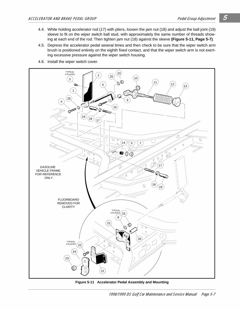
ACCELERATOR AND BRAKE PEDAL GROUP Pedal Group Adjustment 5
4.4. While holding accelerator rod (17) with pliers, loosen the jam nut (18) and adjust the ball joint (19)sleeve to fit on the wiper switch ball stud, with approximately the same number of threads show-ing at each end of the rod. Then tighten jam nut (18) against the sleeve (Figure 5-11, Page 5-7) .
4.5. Depress the accelerator pedal several times and then check to be sure that the wiper switch armbrush is positioned entirely on the eighth fixed contact, and that the wiper switch arm is not exert-ing excessive pressure against the wiper switch housing.
4.6. Install the wiper switch cover.
Figure 5-11 Accelerator Pedal Assembly and Mounting
TYPICAL4 PLACES
TYPICAL4 PLACES
23
24
22
21
21
815
20
TYPICAL4 PLACES
FLOORBOARDREMOVED FOR
CLARITY
14 5 7
19
425
1
3
1817
16
9
13
1918
17
1211
102
23
6
25
GASOLINE VEHICLE FRAMEFOR REFERENCE
ONLY
1998/1999 DS Golf Car Maintenance and Service Manual Page 5-7
ACCELERATOR AND BRAKE PEDAL GROUP Pedal Group Disassembly and Assembly5
PEDAL GROUP DISASSEMBLY AND ASSEMBLY
Removing the Brake Pedal Assembly1. Make sure key switch is OFF and that the Forward/Reverse handle is in NEUTRAL, then disconnect
battery or batteries as instructed in WARNING on pages 5-1 and 5-2. See following CAUTION .
2. Place chocks under the rear wheels and lift the front end of the vehicle with a chain hoist or floor jack.Place jackstands under the front cross tube of the vehicle frame and lower the vehicle onto the jack-stands. See following WARNING .
3. Remove the brake pedal assembly.
3.1. Disconnect the brake cables from the equalizer rod (14) (Figure 5-12, Page 5-9) .
3.2. Remove the pedal return spring (11) from the equalizer rod (14) (Figure 5-12, Page 5-9) .
3.3. Remove nuts (34), flat washers (27), bolts (28), and bearing blocks (26) (Figure 5-12, Page 5-9) .
3.4. Loosen the brake equalizer rod hex nut (5) five turns, then disconnect the rod (14) from the pedalshaft by removing the bolt (15) and nut (16) (Figure 5-12, Page 5-9) .
3.5. Remove the nut (25) and brake stop (24) (Figure 5-12, Page 5-9) .
3.6. Lift the pedal assembly (10) up through the floorboard (Figure 5-12, Page 5-9) .
Installing the Brake Pedal Assembly1. Install the brake pedal assembly.
1.1. From the top side of the floorboard, insert the brake pedal weldment assembly (10) (Figure 5-12,Page 5-9) through the opening in the floor as shown (Figure 5-13, Page 5-11) , and install thepedal stop (24) (Figure 5-12, Page 5-9) on the weldment.
1.2. Attach the equalizer rod (14) to the brake pedal weldment assembly (10) as shown (Figure 5-12,Page 5-9). Tighten the bolt (15) and nut (16) to 17 ft.lb (23.1 N-m).
1.3. Position and attach brake pedal assembly and mounting blocks (26) to vehicle frame as shown.Tighten the bolts and nuts to 50 in.lb (6.5 N-m) (Figure 5-12, Page 5-9) . See following NOTE .
• BEFORE DISCONNECTING BATTERIES, READ WARNING ON PAGES 5-1 AND 5-2.
• LIFT ONLY ONE END OF A VEHICLE AT A TIME. BEFORE LIFTING, LOCK THE BRAKES ANDCHOCK THE WHEELS THAT REMAIN ON THE FLOOR. USE A SUITABLE LIFTING DEVICE(CHAIN HOIST OR HYDRAULIC FLOOR JACK) WITH 1000 LBS. (454 KG.) MINIMUM LIFTINGCAPACITY. DO NOT USE LIFTING DEVICE TO HOLD VEHICLE IN RAISED POSITION. ALWAYSUSE APPROVED JACKSTANDS OF PROPER WEIGHT CAPACITY TO SUPPORT THE VEHICLE.
• EACH HALF OF EACH MOUNTING BLOCK ASSEMBLY IS MARKED WITH AN A OR B. THEHALVES MARKED A SHOULD BE ORIENTED TO THE TOP LEFT HAND AND BOTTOM RIGHTHAND SIDES OF THE BRAKE PEDAL ASSEMBLY, AND THE HALVES MARKED B SHOULD BEORIENTED TO THE TOP RIGHT HAND SIDE AND BOTTOM LEFT HAND SIDE OF THE BRAKEPEDAL ASSEMBLY (FIGURE 5-12, PAGE 5-9).
CAUTION
WARNING
NOTE
Page 5-8 1998/1999 DS Golf Car Maintenance and Service Manual

ACCELERATOR AND BRAKE PEDAL GROUP Pedal Group Disassembly and Assembly 5
1.4. Install the brake cables (6) on the equalizer rod using new cotter pins (8) and the clevis pins (9)that were removed when the brake pedal assembly was disassembled (Figure 5-12, Page 5-9) .Tighten the nut (5) on the equalizer rod so that brake pedal free-play is 1/4 in. to 1/2 in. (6.35 mmto 12.7 mm) (Figure 5-16, Page 5-11). See following NOTE.
• BRAKE PEDAL FREE-PLAY IS THE DISTANCE THE BRAKE PEDAL CAN BE DEPRESSEDBEFORE THE BRAKE ACTUATOR ARM MOVES.
Figure 5-12 Brake and Park Brake Pedal Assembly and Mounting
NOTE
STOP
A
A
B
B
27
28
TYPICAL4 PLACES
FLOORBOARDREMOVED FOR
CLARITY
REFERENCEGASOLINE VEHICLE
FRAME
29
32 3033
TYPICAL2 PLACES
31
12TYPICAL4 PLACES
21
20
17
25
23
3022
10
13
18
19
24
35
34
26
TYPICAL2 PLACES
1516
14
21
4
511
3
2
98
TYPICAL2 PLACES
67
1998/1999 DS Golf Car Maintenance and Service Manual Page 5-9
ACCELERATOR AND BRAKE PEDAL GROUP Pedal Group Disassembly and Assembly5
Removing the Park Brake Assembly1. Make sure the key switch is off and that the Forward/Reverse handle is in NEUTRAL, then disconnect
the battery or batteries as instructed in WARNING on pages 5-1 and 5-2. See following CAUTION .
2. Place chocks under the rear wheels and lift the front end of the vehicle with a chain hoist or floor jack.Place jackstands under the front cross tube of the vehicle frame and lower the vehicle onto the jack-stands. See following WARNING .
3. Remove the park brake assembly.
3.1. To remove the park brake rod and pawl assembly (17 through 20 and 35), remove the push-on nut(19) and disconnect the ball joint sleeve (21) from the park brake pedal (29). Remove the ball jointsleeve (20) from the rod and pawl assembly (Figure 5-12, Page 5-9). See following NOTE .
3.2. To remove the park brake pedal (1), remove the push-on retainer nut (32), disconnect the torsionspring (22) (Figure 5-14, Page 5-11) and slide the pedal off of the shaft. See following NOTE .
3.3. Inspect all parts for wear or damage and replace as necessary.
Installing the Park Brake Assembly1. From the bottom side of the floorboard, insert the park brake rod (17) through the brake pedal assem-
bly opening as shown (Figure 5-14, Page 5-11) . Then install the park brake pawl (35) onto the shaft onthe brake pedal assembly weldment (10) and also the park brake rod (17) into the park brake pawl(Figure 5-14, Page 5-11) .
2. Install the push nut (19) onto the park brake pawl shaft (Figure 5-14, Page 5-11) .
3. Install the spacer (23) and torsion spring (22) on the park brake pedal shaft on the brake pedal weld-ment (Figure 5-14, Page 5-11) .
4. Install the two bushings (30) in the park brake pedal and position the park brake pedal on the shaft onthe brake pedal assembly weldment (Figure 5-14, Page 5-11) . Then attach the ends of the torsionspring to the park brake pedal and to the brake pedal weldment as shown (Figure 5-15, Page 5-11) .
• BEFORE DISCONNECTING BATTERIES, READ WARNING ON PAGES 5-1 AND 5-2.
• LIFT ONLY ONE END OF THE VEHICLE AT A TIME. BEFORE LIFTING, LOCK THE BRAKES ANDCHOCK THE WHEELS THAT REMAIN ON THE FLOOR. USE A SUITABLE LIFTING DEVICE(CHAIN HOIST OR HYDRAULIC FLOOR JACK) WITH 1000 LBS. (454 KG.) MINIMUM LIFTINGCAPACITY. DO NOT USE LIFTING DEVICE TO HOLD VEHICLE IN RAISED POSITION. ALWAYSUSE APPROVED JACKSTANDS OF PROPER WEIGHT CAPACITY TO SUPPORT THE VEHICLE.
• A NEW PUSH-ON NUT (19) (FIGURE 5-14, PAGE 5-11) MUST BE USED WHEN REASSEMBLINGTHE PARK BRAKE.
• A NEW PUSH-ON NUT (32) (FIGURE 5-14, PAGE 5-11) MUST BE USED WHEN REASSEMBLINGTHE PARK BRAKE.
CAUTION
WARNING
NOTE
NOTE
Page 5-10 1998/1999 DS Golf Car Maintenance and Service Manual
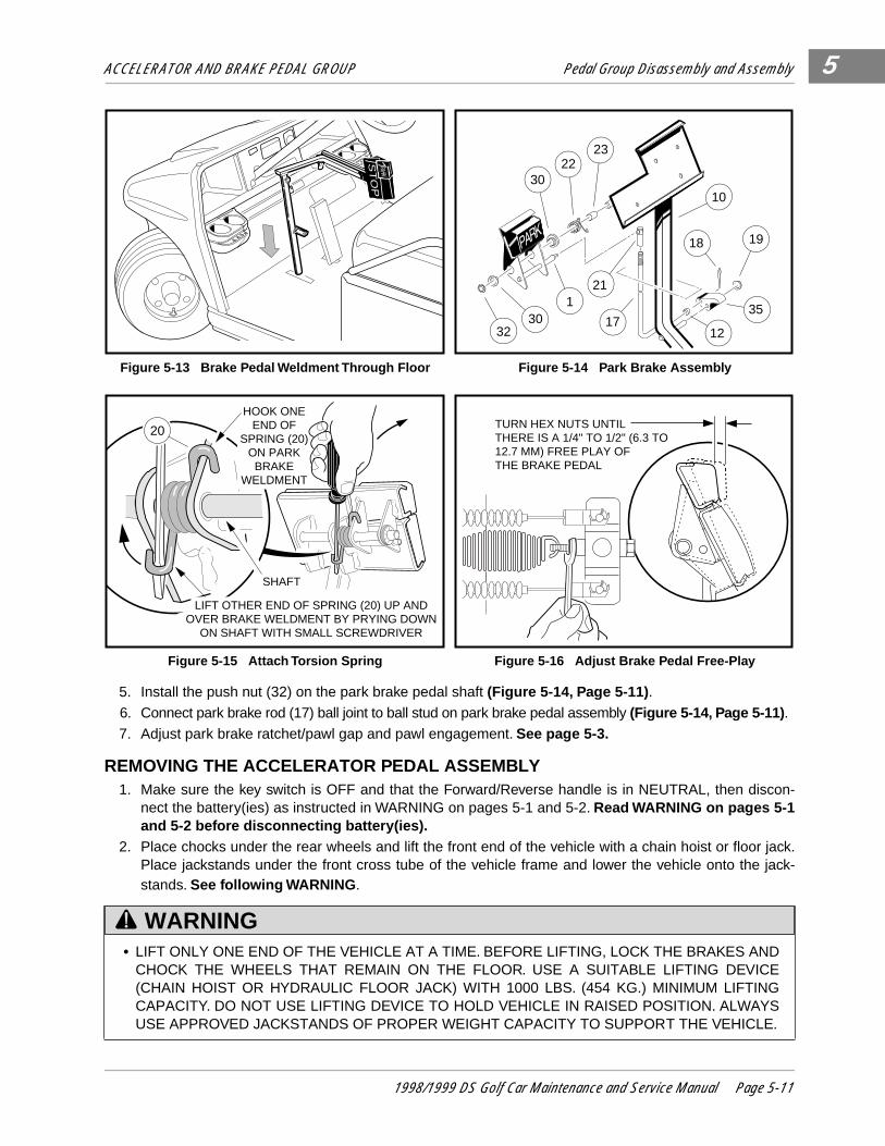
ACCELERATOR AND BRAKE PEDAL GROUP Pedal Group Disassembly and Assembly 5
5. Install the push nut (32) on the park brake pedal shaft (Figure 5-14, Page 5-11) .
6. Connect park brake rod (17) ball joint to ball stud on park brake pedal assembly (Figure 5-14, Page 5-11) .
7. Adjust park brake ratchet/pawl gap and pawl engagement. See page 5-3.
REMOVING THE ACCELERATOR PEDAL ASSEMBLY1. Make sure the key switch is OFF and that the Forward/Reverse handle is in NEUTRAL, then discon-
nect the battery(ies) as instructed in WARNING on pages 5-1 and 5-2. Read WARNING on pages 5-1and 5-2 before disconnecting battery(ies).
2. Place chocks under the rear wheels and lift the front end of the vehicle with a chain hoist or floor jack.Place jackstands under the front cross tube of the vehicle frame and lower the vehicle onto the jack-stands. See following WARNING .
Figure 5-13 Brake Pedal Weldment Through Floor Figure 5-14 Park Brake Assembly
Figure 5-15 Attach Torsion Spring Figure 5-16 Adjust Brake Pedal Free-Play
• LIFT ONLY ONE END OF THE VEHICLE AT A TIME. BEFORE LIFTING, LOCK THE BRAKES ANDCHOCK THE WHEELS THAT REMAIN ON THE FLOOR. USE A SUITABLE LIFTING DEVICE(CHAIN HOIST OR HYDRAULIC FLOOR JACK) WITH 1000 LBS. (454 KG.) MINIMUM LIFTINGCAPACITY. DO NOT USE LIFTING DEVICE TO HOLD VEHICLE IN RAISED POSITION. ALWAYSUSE APPROVED JACKSTANDS OF PROPER WEIGHT CAPACITY TO SUPPORT THE VEHICLE.
ST
OP
130
32
3022
23
10
21
1217
18 19
35
LIFT OTHER END OF SPRING (20) UP AND OVER BRAKE WELDMENT BY PRYING DOWN
ON SHAFT WITH SMALL SCREWDRIVER
SHAFT
20
HOOK ONEEND OF
SPRING (20)ON PARKBRAKE
WELDMENT
TURN HEX NUTS UNTIL THERE IS A 1/4" TO 1/2" (6.3 TO12.7 MM) FREE PLAY OFTHE BRAKE PEDAL
WARNING
1998/1999 DS Golf Car Maintenance and Service Manual Page 5-11
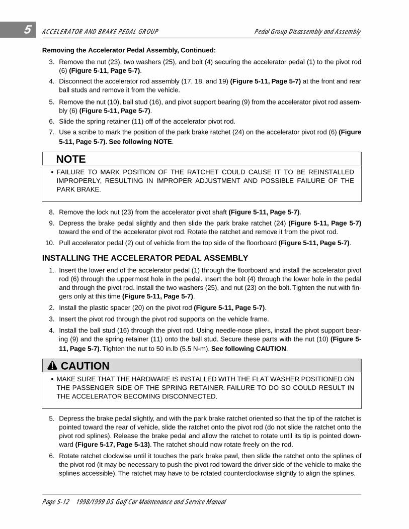
ACCELERATOR AND BRAKE PEDAL GROUP Pedal Group Disassembly and Assembly5
Removing the Accelerator Pedal Assembly, Continued:3. Remove the nut (23), two washers (25), and bolt (4) securing the accelerator pedal (1) to the pivot rod(6) (Figure 5-11, Page 5-7) .
4. Disconnect the accelerator rod assembly (17, 18, and 19) (Figure 5-11, Page 5-7) at the front and rearball studs and remove it from the vehicle.
5. Remove the nut (10), ball stud (16), and pivot support bearing (9) from the accelerator pivot rod assem-bly (6) (Figure 5-11, Page 5-7) .
6. Slide the spring retainer (11) off of the accelerator pivot rod.
7. Use a scribe to mark the position of the park brake ratchet (24) on the accelerator pivot rod (6) (Figure5-11, Page 5-7). See following NOTE .
8. Remove the lock nut (23) from the accelerator pivot shaft (Figure 5-11, Page 5-7) .
9. Depress the brake pedal slightly and then slide the park brake ratchet (24) (Figure 5-11, Page 5-7)toward the end of the accelerator pivot rod. Rotate the ratchet and remove it from the pivot rod.
10. Pull accelerator pedal (2) out of vehicle from the top side of the floorboard (Figure 5-11, Page 5-7) .
INSTALLING THE ACCELERATOR PEDAL ASSEMBLY1. Insert the lower end of the accelerator pedal (1) through the floorboard and install the accelerator pivot
rod (6) through the uppermost hole in the pedal. Insert the bolt (4) through the lower hole in the pedaland through the pivot rod. Install the two washers (25), and nut (23) on the bolt. Tighten the nut with fin-gers only at this time (Figure 5-11, Page 5-7) .
2. Install the plastic spacer (20) on the pivot rod (Figure 5-11, Page 5-7) .
3. Insert the pivot rod through the pivot rod supports on the vehicle frame.
4. Install the ball stud (16) through the pivot rod. Using needle-nose pliers, install the pivot support bear-ing (9) and the spring retainer (11) onto the ball stud. Secure these parts with the nut (10) (Figure 5-11, Page 5-7). Tighten the nut to 50 in.lb (5.5 N-m). See following CAUTION .
5. Depress the brake pedal slightly, and with the park brake ratchet oriented so that the tip of the ratchet ispointed toward the rear of vehicle, slide the ratchet onto the pivot rod (do not slide the ratchet onto thepivot rod splines). Release the brake pedal and allow the ratchet to rotate until its tip is pointed down-ward (Figure 5-17, Page 5-13) . The ratchet should now rotate freely on the rod.
6. Rotate ratchet clockwise until it touches the park brake pawl, then slide the ratchet onto the splines ofthe pivot rod (it may be necessary to push the pivot rod toward the driver side of the vehicle to make thesplines accessible). The ratchet may have to be rotated counterclockwise slightly to align the splines.
• FAILURE TO MARK POSITION OF THE RATCHET COULD CAUSE IT TO BE REINSTALLEDIMPROPERLY, RESULTING IN IMPROPER ADJUSTMENT AND POSSIBLE FAILURE OF THEPARK BRAKE.
• MAKE SURE THAT THE HARDWARE IS INSTALLED WITH THE FLAT WASHER POSITIONED ONTHE PASSENGER SIDE OF THE SPRING RETAINER. FAILURE TO DO SO COULD RESULT INTHE ACCELERATOR BECOMING DISCONNECTED.
NOTE
CAUTION
Page 5-12 1998/1999 DS Golf Car Maintenance and Service Manual
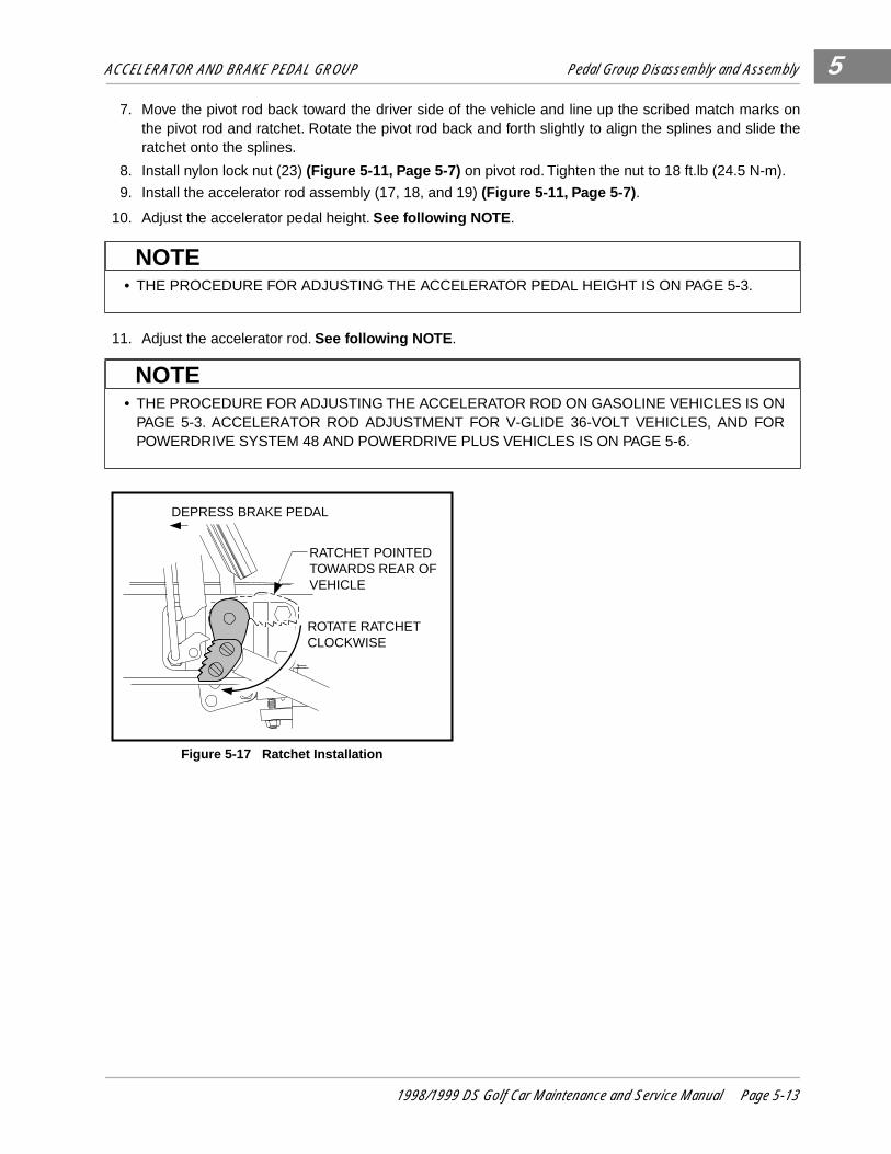
ACCELERATOR AND BRAKE PEDAL GROUP Pedal Group Disassembly and Assembly 5
7. Move the pivot rod back toward the driver side of the vehicle and line up the scribed match marks onthe pivot rod and ratchet. Rotate the pivot rod back and forth slightly to align the splines and slide theratchet onto the splines.
8. Install nylon lock nut (23) (Figure 5-11, Page 5-7) on pivot rod. Tighten the nut to 18 ft.lb (24.5 N-m).
9. Install the accelerator rod assembly (17, 18, and 19) (Figure 5-11, Page 5-7) .
10. Adjust the accelerator pedal height. See following NOTE .
11. Adjust the accelerator rod. See following NOTE .
• THE PROCEDURE FOR ADJUSTING THE ACCELERATOR PEDAL HEIGHT IS ON PAGE 5-3.
• THE PROCEDURE FOR ADJUSTING THE ACCELERATOR ROD ON GASOLINE VEHICLES IS ONPAGE 5-3. ACCELERATOR ROD ADJUSTMENT FOR V-GLIDE 36-VOLT VEHICLES, AND FORPOWERDRIVE SYSTEM 48 AND POWERDRIVE PLUS VEHICLES IS ON PAGE 5-6.
Figure 5-17 Ratchet Installation
NOTE
NOTE
RATCHET POINTED TOWARDS REAR OF VEHICLE
ROTATE RATCHET CLOCKWISE
DEPRESS BRAKE PEDAL
1998/1999 DS Golf Car Maintenance and Service Manual Page 5-13

5
6
SECTION 6–WHEEL BRAKE ASSEMBLIES
DS Golf Cars, both gasoline and electric, are equipped with self-adjusting , mechanically expanding shoedrum brakes on each rear wheel.
• ONLY TRAINED MECHANICS SHOULD REPAIR OR SERVICE THIS VEHICLE. ANYONE DOINGEVEN SIMPLE REPAIRS OR SERVICE SHOULD HAVE KNOWLEDGE AND EXPERIENCE INGENERAL REPAIR.
• FOLLOW ALL PROCEDURES EXACTLY AS STATED IN THIS MANUAL, AND HEED ALL DAN-GER, WARNING, AND CAUTION STATEMENTS LISTED IN THIS MANUAL, AS WELL AS THOSEAFFIXED TO THE VEHICLE.
• ALWAYS WEAR SAFETY GLASSES OR APPROVED EYE PROTECTION WHILE SERVICINGVEHICLE. WEAR A FULL FACE SHIELD WHEN WORKING WITH BATTERIES.
• TURN KEY SWITCH OFF, REMOVE THE KEY, PLACE FORWARD/REVERSE HANDLE IN THENEUTRAL POSITION, CHOCK THE WHEELS, AND DISCONNECT THE BATTERY(IES) PRIORTO SERVICING THE VEHICLE.
• SOME BRAKE SHOES CONTAIN ASBESTOS FIBER, AND ASBESTOS DUST IS CREATEDWHEN THESE BRAKE MECHANISMS ARE HANDLED. WEAR APPROVED EYE AND RESPIRA-TORY PROTECTION WHEN DISASSEMBLING AND CLEANING BRAKE MECHANISMS. INHALA-TION OF ASBESTOS COULD RESULT IN SEVERE PERSONAL INJURY OR DEATH. DO NOTUSE COMPRESSED AIR OR AEROSOL SPRAYS TO CLEAN THE BRAKE MECHANISM. CLEANBRAKE MECHANISMS USING THE NEGATIVE PRESSURE ENCLOSURE/HEPA VACUUM SYS-TEM OR LOW PRESSURE/WET CLEANING METHOD PER OSHA/29 CFR - 1910.1001.
• MOVING PARTS! - DO NOT ATTEMPT TO SERVICE THE VEHICLE WHILE IT IS RUNNING.
• DO NOT WEAR LOOSE CLOTHING. REMOVE JEWELRY SUCH AS RINGS, WATCHES, CHAINS,ETC. BEFORE SERVICING VEHICLE.
GASOLINE VEHICLES ONLY:
• TO AVOID UNINTENTIONALLY STARTING THE VEHICLE:
- DISCONNECT BATTERY CABLES, NEGATIVE (-) FIRST (SECTION 1, FIGURE 1-1).- DISCONNECT THE SPARK PLUG WIRE FROM THE SPARK PLUG.
• FRAME GROUND - DO NOT ALLOW TOOLS OR OTHER METAL OBJECTS TO CONTACTFRAME WHEN DISCONNECTING BATTERY CABLES OR OTHER ELECTRIC WIRING. NEVERALLOW A POSITIVE WIRE TO TOUCH THE VEHICLE FRAME, ENGINE, OR OTHER METALCOMPONENT.
ELECTRIC VEHICLES ONLY:
• TO AVOID UNINTENTIONALLY STARTING THE VEHICLE, DISCONNECT BATTERIES AS SHOWN(SECTION 1, FIGURE 1-2 OR 1-3).
• ON POWERDRIVE PLUS VEHICLES, PLACE THE TOW/RUN SWITCH IN THE TOW POSITIONBEFORE DISCONNECTING BATTERIES.
• ON POWERDRIVE SYSTEM 48 VEHICLES, DISCHARGE THE CONTROLLER AS FOLLOWSAFTER DISCONNECTING BATTERIES:
- TURN THE KEY SWITCH TO ON AND PLACE THE FORWARD/REVERSE HANDLE IN THEREVERSE POSITION.
- SLOWLY DEPRESS THE ACCELERATOR PEDAL AND KEEP IT DEPRESSED UNTIL THEREVERSE WARNING BUZZER CAN NO LONGER BE HEARD. WHEN THE BUZZER STOPSSOUNDING, THE CONTROLLER IS DISCHARGED.
WARNING
1998 DS Golf Car Maintenance and Service Manual Page 6-1

WHEEL BRAKE ASSEMBLIES
6
• LIFT ONLY ONE END OF THE VEHICLE AT A TIME. BEFORE LIFTING, LOCK THE BRAKES ANDCHOCK THE WHEELS THAT REMAIN ON THE FLOOR. USE A SUITABLE LIFTING DEVICE(CHAIN HOIST OR HYDRAULIC FLOOR JACK) WITH 1000 LBS. (454 KG.) MINIMUM LIFTINGCAPACITY. DO NOT USE LIFTING DEVICE TO HOLD VEHICLE IN RAISED POSITION. ALWAYSUSE APPROVED JACKSTANDS OF PROPER WEIGHT CAPACITY TO SUPPORT THE VEHICLE.
Figure 6-1 Self-adjusting Wheel Brake Assembly
WARNING
18
8
6
9
4
3
2
13
12���������
yyyyyyyyy
����yyyy
6
5
7TYPICAL 2PLACES
7TYPICAL 2PLACES
11TYPICAL 4PLACES 10
TYPICAL 4PLACES
16
1414
SEE REAR SUSPENSION - SECTION 9 FOR MOUNTING
15
ELECTRIC VEHICLEONLY GASOLINE VEHICLE
ONLY
Page 6-2 1998 DS Golf Car Maintenance and Service Manual

WHEEL BRAKE ASSEMBLIES Removal and Cleaning of Wheel Brake Assemblies
6
REMOVAL AND CLEANING OF WHEEL BRAKE ASSEMBLIES
REMOVE THE BRAKE SHOES AND CLEAN THE BRAKE ASSEMBLY
1. Place chocks at the front wheels. Loosen, but do not remove, lug nuts on rear wheels and lift the rear ofthe vehicle with a chain hoist or floor jack. Place jackstands under the axle tubes to support the vehicle.
2. Loosen the equalizer retaining nuts (1) on the equalizer rod (2) to slightly loosen the brake cable (Fig-ure 6-2, Page 6-3) .
3. Remove rear wheel lug nuts and rear wheels and then the brake drums. If the brake drums cannot beremoved, see the following NOTE. Otherwise, proceed to step 5.
• SOME BRAKE SHOES CONTAIN ASBESTOS FIBER AND ASBESTOS DUST IS CREATED WHENTHESE BRAKE MECHANISMS ARE HANDLED. WEAR APPROVED EYE AND RESPIRATORYPROTECTION WHEN DISASSEMBLING AND CLEANING BRAKE MECHANISMS. INHALATIONOF ASBESTOS COULD RESULT IN SEVERE PERSONAL INJURY OR DEATH. DO NOT USECOMPRESSED AIR OR AEROSOL SPRAYS TO CLEAN THE BRAKE MECHANISM. CLEANBRAKE MECHANISMS USING THE NEGATIVE PRESSURE ENCLOSURE/HEPA VACUUM SYS-TEM OR LOW PRESSURE/WET CLEANING METHOD PER OSHA/29 CFR - 1910.1001.
Figure 6-2 Loosen Equalizer Retaining Nuts Figure 6-3 Remove Axle Retaining Ring
• LIFT ONLY ONE END OF THE VEHICLE AT A TIME. BEFORE LIFTING, LOCK THE BRAKES ANDCHOCK THE WHEELS THAT REMAIN ON THE FLOOR. USE A SUITABLE LIFTING DEVICE(CHAIN HOIST OR HYDRAULIC FLOOR JACK) WITH 1000 LBS. (454 KG.) MINIMUM LIFTINGCAPACITY. DO NOT USE LIFTING DEVICE TO HOLD VEHICLE IN RAISED POSITION. ALWAYSUSE APPROVED JACKSTANDS OF PROPER WEIGHT CAPACITY TO SUPPORT THE VEHICLE.
• WHEN SERVICING VEHICLES WITH SEVERELY WORN BRAKE SHOES AND WHEN THEDRUMS CANNOT BE REMOVED BY NORMAL METHODS, PROCEED TO STEP 4 TO MINIMIZEDAMAGE TO THE BRAKE CLUSTER AND BRAKE COMPONENTS.
WARNING
2
1
1
2
WARNING
NOTE
1998 DS Golf Car Maintenance and Service Manual Page 6-3
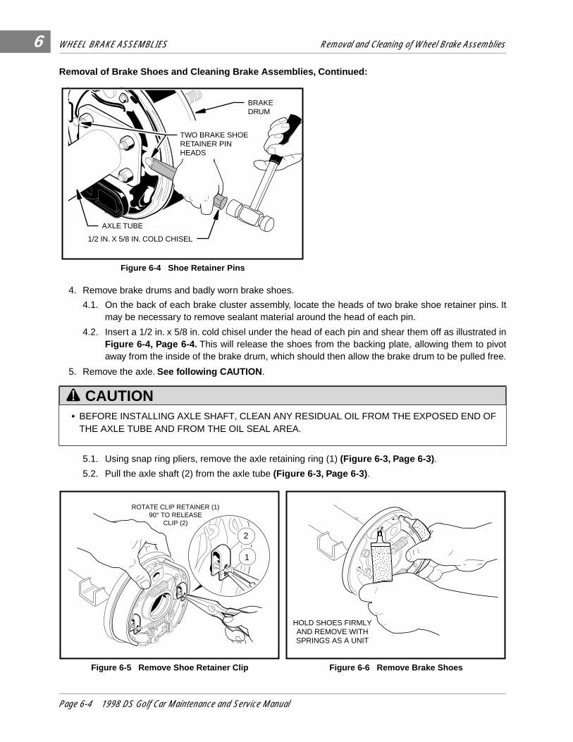
WHEEL BRAKE ASSEMBLIES Removal and Cleaning of Wheel Brake Assemblies
6
Removal of Brake Shoes and Cleaning Brake Assemblies, Continued:
4. Remove brake drums and badly worn brake shoes.
4.1. On the back of each brake cluster assembly, locate the heads of two brake shoe retainer pins. Itmay be necessary to remove sealant material around the head of each pin.
4.2. Insert a 1/2 in. x 5/8 in. cold chisel under the head of each pin and shear them off as illustrated inFigure 6-4, Page 6-4. This will release the shoes from the backing plate, allowing them to pivotaway from the inside of the brake drum, which should then allow the brake drum to be pulled free.
5. Remove the axle. See following CAUTION .
5.1. Using snap ring pliers, remove the axle retaining ring (1) (Figure 6-3, Page 6-3) .
5.2. Pull the axle shaft (2) from the axle tube (Figure 6-3, Page 6-3) .
Figure 6-4 Shoe Retainer Pins
• BEFORE INSTALLING AXLE SHAFT, CLEAN ANY RESIDUAL OIL FROM THE EXPOSED END OFTHE AXLE TUBE AND FROM THE OIL SEAL AREA.
Figure 6-5 Remove Shoe Retainer Clip Figure 6-6 Remove Brake Shoes
���������
yyyyyyyyy
����yyyy
AXLE TUBE
1/2 IN. X 5/8 IN. COLD CHISEL
BRAKE DRUM
TWO BRAKE SHOE RETAINER PIN HEADS
CAUTION
1
2
ROTATE CLIP RETAINER (1)90° TO RELEASE
CLIP (2)
������yz{{||����yz{|��yz
HOLD SHOES FIRMLYAND REMOVE WITH SPRINGS AS A UNIT
Page 6-4 1998 DS Golf Car Maintenance and Service Manual
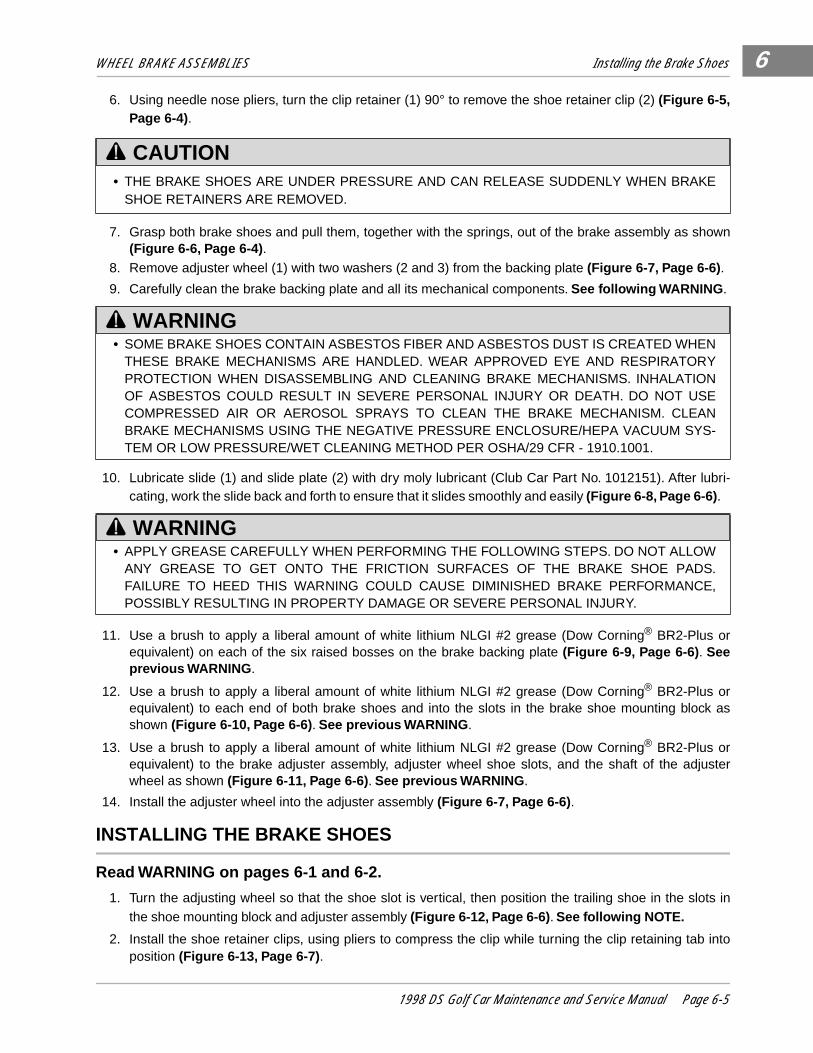
WHEEL BRAKE ASSEMBLIES Installing the Brake Shoes
6
6. Using needle nose pliers, turn the clip retainer (1) 90° to remove the shoe retainer clip (2) (Figure 6-5,Page 6-4).
7. Grasp both brake shoes and pull them, together with the springs, out of the brake assembly as shown(Figure 6-6, Page 6-4) .
8. Remove adjuster wheel (1) with two washers (2 and 3) from the backing plate (Figure 6-7, Page 6-6) .
9. Carefully clean the brake backing plate and all its mechanical components. See following WARNING .
10. Lubricate slide (1) and slide plate (2) with dry moly lubricant (Club Car Part No. 1012151). After lubri-cating, work the slide back and forth to ensure that it slides smoothly and easily (Figure 6-8, Page 6-6) .
11. Use a brush to apply a liberal amount of white lithium NLGI #2 grease (Dow Corning® BR2-Plus orequivalent) on each of the six raised bosses on the brake backing plate (Figure 6-9, Page 6-6) . Seeprevious WARNING .
12. Use a brush to apply a liberal amount of white lithium NLGI #2 grease (Dow Corning® BR2-Plus orequivalent) to each end of both brake shoes and into the slots in the brake shoe mounting block asshown (Figure 6-10, Page 6-6) . See previous WARNING .
13. Use a brush to apply a liberal amount of white lithium NLGI #2 grease (Dow Corning® BR2-Plus orequivalent) to the brake adjuster assembly, adjuster wheel shoe slots, and the shaft of the adjusterwheel as shown (Figure 6-11, Page 6-6) . See previous WARNING .
14. Install the adjuster wheel into the adjuster assembly (Figure 6-7, Page 6-6) .
INSTALLING THE BRAKE SHOES
Read WARNING on pages 6-1 and 6-2.
1. Turn the adjusting wheel so that the shoe slot is vertical, then position the trailing shoe in the slots inthe shoe mounting block and adjuster assembly (Figure 6-12, Page 6-6) . See following NOTE.
2. Install the shoe retainer clips, using pliers to compress the clip while turning the clip retaining tab intoposition (Figure 6-13, Page 6-7) .
• THE BRAKE SHOES ARE UNDER PRESSURE AND CAN RELEASE SUDDENLY WHEN BRAKESHOE RETAINERS ARE REMOVED.
• SOME BRAKE SHOES CONTAIN ASBESTOS FIBER AND ASBESTOS DUST IS CREATED WHENTHESE BRAKE MECHANISMS ARE HANDLED. WEAR APPROVED EYE AND RESPIRATORYPROTECTION WHEN DISASSEMBLING AND CLEANING BRAKE MECHANISMS. INHALATIONOF ASBESTOS COULD RESULT IN SEVERE PERSONAL INJURY OR DEATH. DO NOT USECOMPRESSED AIR OR AEROSOL SPRAYS TO CLEAN THE BRAKE MECHANISM. CLEANBRAKE MECHANISMS USING THE NEGATIVE PRESSURE ENCLOSURE/HEPA VACUUM SYS-TEM OR LOW PRESSURE/WET CLEANING METHOD PER OSHA/29 CFR - 1910.1001.
• APPLY GREASE CAREFULLY WHEN PERFORMING THE FOLLOWING STEPS. DO NOT ALLOWANY GREASE TO GET ONTO THE FRICTION SURFACES OF THE BRAKE SHOE PADS.FAILURE TO HEED THIS WARNING COULD CAUSE DIMINISHED BRAKE PERFORMANCE,POSSIBLY RESULTING IN PROPERTY DAMAGE OR SEVERE PERSONAL INJURY.
CAUTION
WARNING
WARNING
1998 DS Golf Car Maintenance and Service Manual Page 6-5

WHEEL BRAKE ASSEMBLIES Installing the Brake Shoes
6
Figure 6-7 Remove Adjuster Wheel Figure 6-8 Lubricate Slide and Slide Plate
Figure 6-9 Apply Grease On Bosses Figure 6-10 Apply Grease To Brake Shoes and Slots
Figure 6-11 Apply Grease To Brake Adjuster Figure 6-12 Install Adjuster Wheel, Trailing Shoe
1
23 LUBRICATE SLIDE (1) AND SLIDE
PLATE (2) WITH DRY MOLY LUBRICANT. THEN WORK THE
SLIDE BACK AND FORTH
1
2
USE A BRUSH TOAPPLY A LIBERAL AMOUNT
OF WHITE LITHIUM NLGI #2 GREASETO EACH OF THE SIX RAISED BOSSES.
BOSSES
BOSSES
��������yyzz{{||
��������yyzz{{||
USE A BRUSH TO APPLY ALIBERAL AMOUNT OF WHITE
LITHIUM NLGI #2 GREASETO THE ENDS OF THE BRAKE
SHOES AND IN THE SHOEMOUNTING SLOTS AS SHOWN.
USE A BRUSH TO APPLY LIBERALAMOUNTS OF WHITE LITHIUM NLGI #2
GREASE TO THE AREAS INDICATED.
TURN ADJUSTING WHEEL SO THAT THE
SHOE SLOT IS VERTICAL
17T STAMPINGON TRAILINGSHOE
FRONT OF
VEHICLE
��{|
17T
Page 6-6 1998 DS Golf Car Maintenance and Service Manual
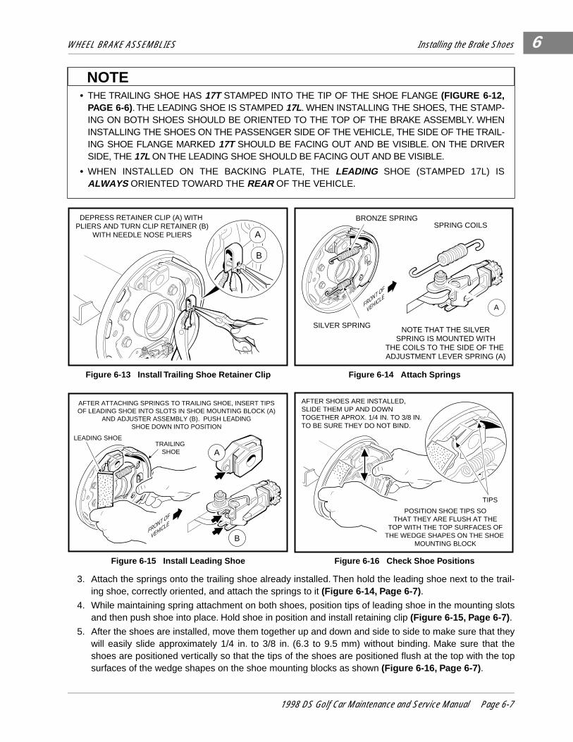
WHEEL BRAKE ASSEMBLIES Installing the Brake Shoes
6
���zz|
3. Attach the springs onto the trailing shoe already installed. Then hold the leading shoe next to the trail-ing shoe, correctly oriented, and attach the springs to it (Figure 6-14, Page 6-7) .
4. While maintaining spring attachment on both shoes, position tips of leading shoe in the mounting slotsand then push shoe into place. Hold shoe in position and install retaining clip (Figure 6-15, Page 6-7) .
5. After the shoes are installed, move them together up and down and side to side to make sure that theywill easily slide approximately 1/4 in. to 3/8 in. (6.3 to 9.5 mm) without binding. Make sure that theshoes are positioned vertically so that the tips of the shoes are positioned flush at the top with the topsurfaces of the wedge shapes on the shoe mounting blocks as shown (Figure 6-16, Page 6-7) .
• THE TRAILING SHOE HAS 17T STAMPED INTO THE TIP OF THE SHOE FLANGE (FIGURE 6-12,PAGE 6-6). THE LEADING SHOE IS STAMPED 17L. WHEN INSTALLING THE SHOES, THE STAMP-ING ON BOTH SHOES SHOULD BE ORIENTED TO THE TOP OF THE BRAKE ASSEMBLY. WHENINSTALLING THE SHOES ON THE PASSENGER SIDE OF THE VEHICLE, THE SIDE OF THE TRAIL-ING SHOE FLANGE MARKED 17T SHOULD BE FACING OUT AND BE VISIBLE. ON THE DRIVERSIDE, THE 17L ON THE LEADING SHOE SHOULD BE FACING OUT AND BE VISIBLE.
• WHEN INSTALLED ON THE BACKING PLATE, THE LEADING SHOE (STAMPED 17L) ISALWAYS ORIENTED TOWARD THE REAR OF THE VEHICLE.
Figure 6-13 Install Trailing Shoe Retainer Clip Figure 6-14 Attach Springs
Figure 6-15 Install Leading Shoe Figure 6-16 Check Shoe Positions
NOTE
A
B
DEPRESS RETAINER CLIP (A) WITH PLIERS AND TURN CLIP RETAINER (B)
WITH NEEDLE NOSE PLIERS
�|NOTE THAT THE SILVER
SPRING IS MOUNTED WITHTHE COILS TO THE SIDE OF THE ADJUSTMENT LEVER SPRING (A)
SPRING COILS
SILVER SPRING
A
BRONZE SPRING
FRONT OF
VEHICLE
����yz{|
AFTER ATTACHING SPRINGS TO TRAILING SHOE, INSERT TIPS OF LEADING SHOE INTO SLOTS IN SHOE MOUNTING BLOCK (A)
AND ADJUSTER ASSEMBLY (B). PUSH LEADING SHOE DOWN INTO POSITION
B
LEADING SHOE
���yy{
TRAILING SHOE A
FRONT OF
VEHICLE
����yz{|������yz{{||
AFTER SHOES ARE INSTALLED,SLIDE THEM UP AND DOWNTOGETHER APROX. 1/4 IN. TO 3/8 IN.TO BE SURE THEY DO NOT BIND.
POSITION SHOE TIPS SOTHAT THEY ARE FLUSH AT THE
TOP WITH THE TOP SURFACES OFTHE WEDGE SHAPES ON THE SHOE
MOUNTING BLOCK
TIPS
1998 DS Golf Car Maintenance and Service Manual Page 6-7
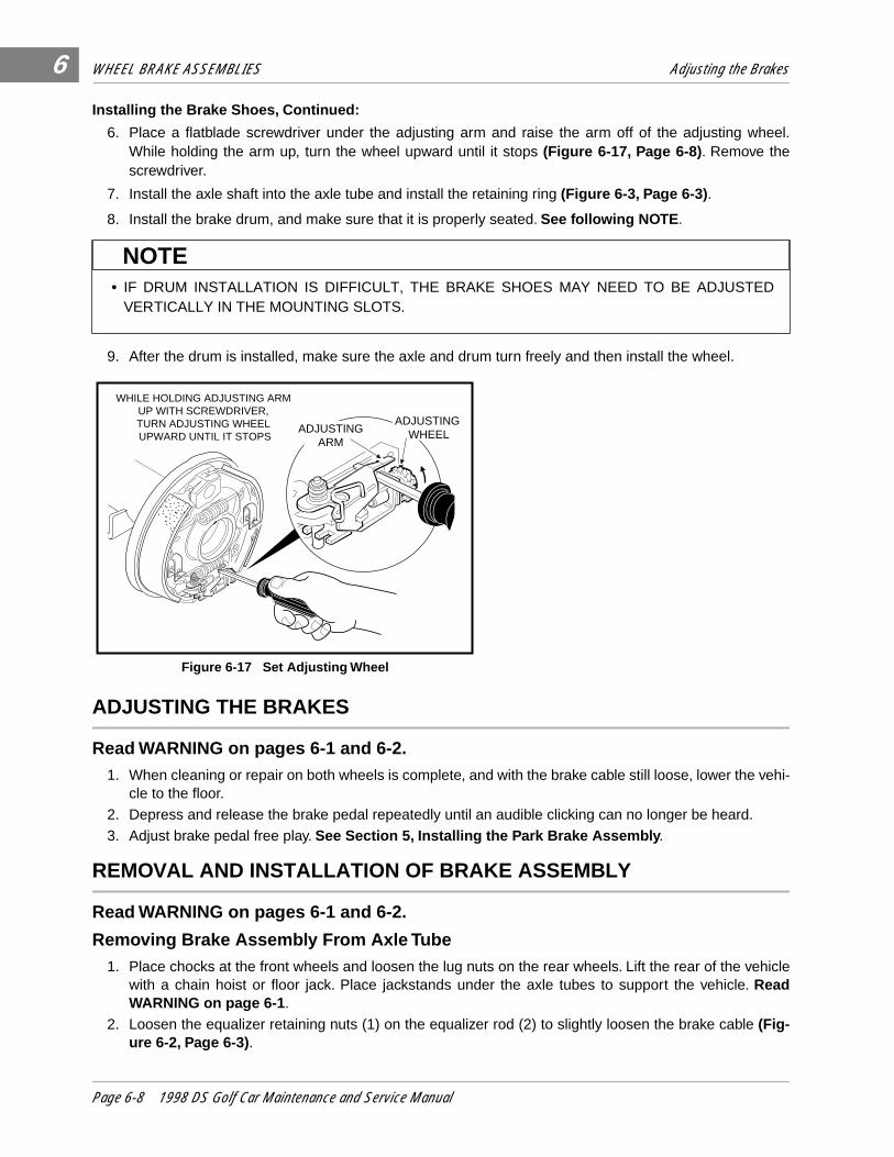
WHEEL BRAKE ASSEMBLIES Adjusting the Brakes
6
Installing the Brake Shoes, Continued:
6. Place a flatblade screwdriver under the adjusting arm and raise the arm off of the adjusting wheel.While holding the arm up, turn the wheel upward until it stops (Figure 6-17, Page 6-8) . Remove thescrewdriver.
7. Install the axle shaft into the axle tube and install the retaining ring (Figure 6-3, Page 6-3) .
8. Install the brake drum, and make sure that it is properly seated. See following NOTE .
9. After the drum is installed, make sure the axle and drum turn freely and then install the wheel.
ADJUSTING THE BRAKES
Read WARNING on pages 6-1 and 6-2.1. When cleaning or repair on both wheels is complete, and with the brake cable still loose, lower the vehi-
cle to the floor.
2. Depress and release the brake pedal repeatedly until an audible clicking can no longer be heard.
3. Adjust brake pedal free play. See Section 5, Installing the Park Brake Assembly .
REMOVAL AND INSTALLATION OF BRAKE ASSEMBLY
Read WARNING on pages 6-1 and 6-2.
Removing Brake Assembly From Axle Tube1. Place chocks at the front wheels and loosen the lug nuts on the rear wheels. Lift the rear of the vehicle
with a chain hoist or floor jack. Place jackstands under the axle tubes to support the vehicle. ReadWARNING on page 6-1 .
2. Loosen the equalizer retaining nuts (1) on the equalizer rod (2) to slightly loosen the brake cable (Fig-ure 6-2, Page 6-3) .
• IF DRUM INSTALLATION IS DIFFICULT, THE BRAKE SHOES MAY NEED TO BE ADJUSTEDVERTICALLY IN THE MOUNTING SLOTS.
Figure 6-17 Set Adjusting Wheel
NOTE
����yz{|
WHILE HOLDING ADJUSTING ARM UP WITH SCREWDRIVER, TURN ADJUSTING WHEEL UPWARD UNTIL IT STOPS
ADJUSTING WHEELADJUSTING
ARM
Page 6-8 1998 DS Golf Car Maintenance and Service Manual
WHEEL BRAKE ASSEMBLIES Removal and Installation of Brake Assembly
6
3. Remove lug nuts and rear wheels and then the brake drums.
4. Remove the axle.
4.1. Using snap ring pliers, remove the axle retaining ring (1) (Figure 6-3, Page 6-3) .
4.2. Pull the axle shaft (2) from the axle tube (Figure 6-3, Page 6-3) .
5. Remove cotter pin (13) and clevis pin (12) from brake cable (Figure 6-1, Page 6-2) .
6. Remove four bolts (11) and lock nuts (10) that mount the brake assembly to the transaxle (Figure 6-1,Page 6-2).
7. Brake assembly can now be removed from transaxle.
Installing Brake Assembly Onto Axle Tube1. Install in reverse order of disassembly.
2. Be sure bolts (11) (Club Car Part No. 1014153) and lock nuts (10) (Club Car Part No. 1013924) areused to mount the brake assembly (Figure 6-1, Page 6-2) .
3. Torque bolts to 30 ft.lb (40.6 N-m).
4. Adjust brakes as previously described in this section.
• BE SURE RETAINING RING IS PROPERLY SEATED IN GROOVE. IF RING IS NOT PROPERLYINSTALLED, THE AXLE ASSEMBLY WILL SEPARATE FROM THE TRANSAXLE AND DAMAGETHE AXLE ASSEMBLY AND OTHER COMPONENTS. LOSS OF CONTROL OF THE VEHICLECOULD RESULT IN SEVERE PERSONAL INJURY OR DEATH.
WARNING
1998 DS Golf Car Maintenance and Service Manual Page 6-9

6
7
SECTION 7–STEERING AND FRONTSUSPENSION
GENERAL INFORMATION - STEERING
Steering is controlled through a rack and pinion steering assembly that is connected by a steering column toa steering wheel.
No manual adjustment to the rack and pinion gear assembly is required. A spring loaded self-adjustingmechanism is incorporated into the assembly.
• ALWAYS WEAR SAFETY GLASSES OR APPROVED EYE PROTECTION WHILE SERVICINGVEHICLE. WEAR A FULL FACE SHIELD WHEN WORKING WITH BATTERIES.
• MOVING PARTS! DO NOT ATTEMPT TO SERVICE THE VEHICLE WHILE IT IS RUNNING.
• USE INSULATED TOOLS WHEN WORKING NEAR BATTERIES OR ELECTRICALCONNECTIONS.
• LIFT ONLY ONE END OF THE VEHICLE AT A TIME. BEFORE LIFTING, LOCK THE BRAKES ANDCHOCK THE WHEELS THAT REMAIN ON THE FLOOR. USE A SUITABLE LIFTING DEVICE(CHAIN HOIST OR HYDRAULIC FLOOR JACK) WITH 1000 LBS. (454 KG.) MINIMUM LIFTINGCAPACITY. DO NOT USE LIFTING DEVICE TO HOLD VEHICLE IN RAISED POSITION. ALWAYSUSE APPROVED JACKSTANDS OF PROPER WEIGHT CAPACITY TO SUPPORT THE VEHICLE.
• TURN KEY SWITCH TO OFF, PLACE FORWARD/REVERSE HANDLE IN THE NEUTRALPOSITION, REMOVE KEY, AND DISCONNECT BATTERY(IES) BEFORE SERVICING THEVEHICLE.
GASOLINE VEHICLES ONLY:
• TO AVOID UNINTENTIONALLY STARTING THE VEHICLE:
- DISCONNECT BATTERY CABLES, NEGATIVE (-) FIRST (SECTION 1, FIGURE 1-1).
- DISCONNECT THE SPARK PLUG WIRE FROM THE SPARK PLUG.
• FRAME GROUND - DO NOT ALLOW UNINSULATED METAL OBJECTS TO CONTACT FRAMEWHEN DISCONNECTING BATTERY CABLES OR OTHER ELECTRICAL WIRING. NEVER ALLOWA POSITIVE WIRE TO TOUCH THE VEHICLE FRAME, ENGINE, OR OTHER METALCOMPONENT.
ELECTRIC VEHICLES ONLY:
• TO AVOID UNINTENTIONALLY STARTING THE VEHICLE, DISCONNECT BATTERIES AS SHOWN(SECTION 1, FIGURE 1-2 OR 1-3).
• ON POWERDRIVE PLUS VEHICLES, PLACE TOW SWITCH IN THE TOW POSITION BEFOREDISCONNECTING BATTERIES.
• ON POWERDRIVE SYSTEM 48 VEHICLES, DISCHARGE THE CONTROLLER AS FOLLOWSAFTER DISCONNECTING THE BATTERIES:
- TURN THE KEY SWITCH TO ON AND PLACE THE FORWARD/REVERSE HANDLE IN THEREVERSE POSITION.
- SLOWLY DEPRESS THE ACCELERATOR PEDAL AND KEEP IT DEPRESSED UNTIL THEREVERSE WARNING BUZZER CAN NO LONGER BE HEARD. WHEN THE BUZZER STOPSSOUNDING, THE CONTROLLER IS DISCHARGED.
WARNING
1998/1999 DS Golf Car Maintenance and Service Manual Page 7-1
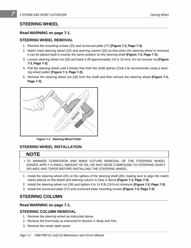
STEERING AND FRONT SUSPENSION Steering Wheel
7
STEERING WHEEL
Read WARNING on page 7-1.
STEERING WHEEL REMOVAL1. Remove the mounting screws (32) and scorecard plate (27) (Figure 7-2, Page 7-3) .
2. Match mark steering wheel (25) and steering column (20) so that when the steering wheel is removedit can be placed back in exactly the same position on the steering shaft (Figure 7-2, Page 7-3) .
3. Loosen steering wheel nut (26) and back it off approximately 1/4 in. (6 mm). Do not remove nut (Figure7-2, Page 7-3).
4. Pull the steering wheel until it breaks free from the shaft splines (Club Car recommends using a steer-ing wheel puller) (Figure 7-1, Page 7-2) .
5. Remove the steering wheel nut (26) from the shaft and then remove the steering wheel (Figure 7-2,Page 7-3).
STEERING WHEEL INSTALLATION
1. Install the steering wheel (25) on the splines of the steering shaft (20), making sure to align the matchmarks placed on the wheel and steering column in Step 2 above (Figure 7-2, Page 7-3) .
2. Install the steering wheel nut (26) and tighten it to 14 ft.lb (19 N-m) minimum (Figure 7-2, Page 7-3) .
3. Install the scorecard plate (27) and scorecard plate mounting screws (Figure 7-2, Page 7-3) .
STEERING COLUMN
Read WARNING on page 7-1.
STEERING COLUMN REMOVAL1. Remove the steering wheel as instructed above.
2. Remove the front body as instructed in Section 4, Body and Trim.
3. Remove the center dash panel.
Figure 7-1 Steering Wheel Puller
• TO MINIMIZE CORROSION AND MAKE FUTURE REMOVAL OF THE STEERING WHEELEASIER, APPLY A SMALL AMOUNT OF OIL OR ANTI-SEIZE COMPOUND TO STEERING SHAFTSPLINES AND TAPER BEFORE INSTALLING THE STEERING WHEEL.
NOTE
Page 7-2 1998/1999 DS Golf Car Maintenance and Service Manual
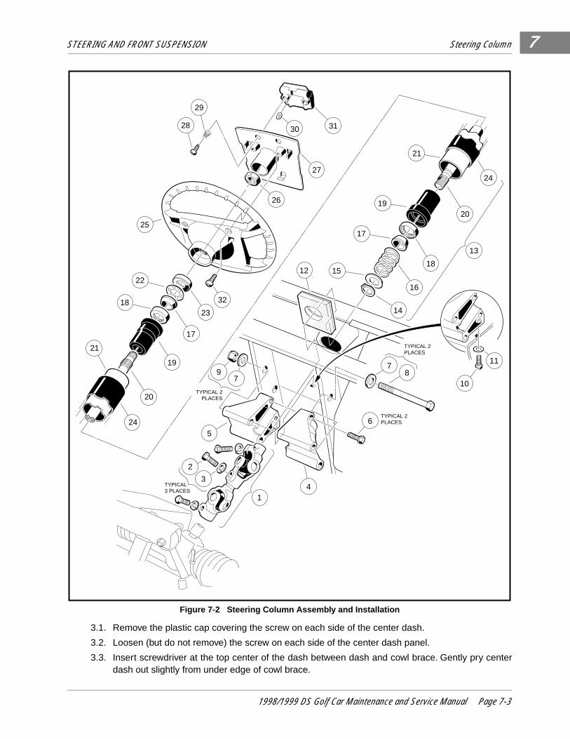
STEERING AND FRONT SUSPENSION Steering Column
7
3.1. Remove the plastic cap covering the screw on each side of the center dash.
3.2. Loosen (but do not remove) the screw on each side of the center dash panel.
3.3. Insert screwdriver at the top center of the dash between dash and cowl brace. Gently pry centerdash out slightly from under edge of cowl brace.
Figure 7-2 Steering Column Assembly and Installation
�y��yy
���
yyy
��������
yyyyyyyy
3130
27
29
28
26
25
22
3218
21
23
17
19
20
24
21
19
17
1512
24
20
18
16
14
13
78
6
41
97
5
2
3
TYPICAL 2PLACES
TYPICAL 2PLACES
TYPICAL 2PLACES
TYPICAL3 PLACES
11
10
1998/1999 DS Golf Car Maintenance and Service Manual Page 7-3
STEERING AND FRONT SUSPENSION Steering Column
7
Steering Column Removal, Continued:
3.4. Pull center dash out approximately 1 in. from the frame and then bend the top right corner inwardwhile pulling the top of the panel out and down.
3.5. Disconnect the wires from the electrical components mounted on the dash panel. Do not allowwires to touch.
3.6. Slide center dash panel up the steering column.
4. Remove the driver side dash pocket.
4.1. Remove cup holder hardware and cup holder.
4.2. Remove the flange lock screw from the top of the dash pocket.
4.3. Drill out the two pop rivets holding the dash pocket in place.
4.4. Slide dash pocket out of vehicle. 5. Remove the upper bolt (2) and lock washer (3) from the universal joint (Figure 7-2, Page 7-3).6. Remove the nuts (9), bolts (8 and 10), and washers (7 and 11) from the steering column mount (4 and
5) (Figure 7-2, Page 7-3) .
7. Remove the steering column from the vehicle.
STEERING COLUMN DISASSEMBLY1. Remove screws (6) and mount (4 and 5) from the steering column (Figure 7-2, Page 7-3) .
2. While supporting the steering shaft (20), remove snap ring (14) from shaft (Figure 7-2, Page 7-3).
3. Remove the washer (15), spring (16), and wedge (17) (Figure 7-2, Page 7-3) .
4. Turn the steering column over and insert a flat blade screwdriver between the seal (23) and the shaft.Pry the seal out of the bearing seat (19) (Figure 7-2, Page 7-3) .
5. Slide the shaft out of the tube to expose the retaining ring (22). Use pliers to twist the retaining ring untilit breaks off, then remove the wedge (17) (Figure 7-2, Page 7-3) .
6. Remove the shaft from the bottom of the tube.
7. Use the steering shaft to push the bearing seat (19) out from the opposite end of the steering tube (21)(Figure 7-2, Page 7-3) .
• BENDING THE TOP RIGHT CORNER OF THE CENTER DASH INWARD DURING REMOVALWILL PREVENT THE CONTACTS ON THE BACK OF THE KEY SWITCH FROM TOUCHING THEMETAL FRAME AROUND THE DASH.
• DO NOT ALLOW THE STEERING SHAFT TO SLIDE OUT OF THE STEERING TUBE WHILEREMOVING THE SNAP RING.
• A NEW SEAL WILL BE REQUIRED FOR REASSEMBLY.
• DO NOT REUSE THE RETAINING RING FOR REASSEMBLY. USE A NEW ONE.
NOTE
NOTE
NOTE
NOTE
Page 7-4 1998/1999 DS Golf Car Maintenance and Service Manual

STEERING AND FRONT SUSPENSION Steering Column
7
8. Insert a flat blade screwdriver between the bottom of the outer race of the bearing and the bottom lip ofthe bearing seat (19) and remove the bearing (18) (Figure 7-2, Page 7-3) .
STEERING COLUMN ASSEMBLY1. Insert the bearing seat (19) into the steering tube (21). Place a block of wood on the bearing seat and
tap lightly on the block until the bearing seat is fully seated in the steering tube (Figure 7-3, Page 7-5) .
2. Press the bearing (18) all the way into the bearing seat (19) using a steering column bearing press tool(Club Car Part No. 1014264) or a metal tube approximately 6 in. (15 cm) long with a maximum outerdiameter of 1-3/16 in. (3.3 cm) and a minimum inside diameter of 7/8 in. (2.2 cm). Be sure the bearingis installed in the bearing seat as shown (Figure 7-3, Page 7-5) so that the wedge (17) will ride againstthe inner race of the bearing.
3. Install the wedge (17), spring (16), washer (15), and snap ring (14) onto the bottom end of the steeringshaft (20) (Figure 7-3, Page 7-5) .
4. Insert the shaft from the bottom of the steering tube.
5. Turn the assembly over and place the shaft on a bench. Install the wedge (17) and retaining ring (22)onto the top of the shaft. Be sure that the prongs on the retaining ring face up and away from thewedge. Use a steering column retaining ring tool (Club Car Part No. 1014259) to seat the retaining ringto the proper depth. If you do not have the recommended tool, use the same tube as was used in Step2 to press the retaining ring onto the top of the shaft. The retaining ring should be pressed onto theshaft until 2 to 2.12 in. (5.1-5.4 centimeters) of the shaft extends from the top of the bearing seat in thesteering tube (Figure 7-4, Page 7-5) .
6. Press the seal (23) into the bearing seat (19) until it is flush with the end of the seat (Figure 7-2, Page7-3). When pressing the seal into the seat, set the steering tube on a bench so that all the pressure isexerted on the steering tube and not on the steering shaft.
• DO NOT DAMAGE THE BEARING OR BEARING SEAT WHILE REMOVING THE BEARING
Figure 7-3 Bottom End of Steering Column Figure 7-4 Top End of Steering Column
CAUTION
WEDGE SEATING INTO THE INNER
RACES OF BEARING
BEARING PRESS TOOL
# 1014264
19
21
20
18
14
15
16
19
17
STEP 1
STEP 2
STEP 3
5.1-5.4 cm2.00-2.12"
COLUMNRETAINING RINGTOOL # 1014259
WEDGE SEATING INTO THE INNER
RACES OF BEARING
BEARING PRESS TOOL
# 1014264
22
21
17
1718
19
STEP 1
STEP 2STEP 3
1998/1999 DS Golf Car Maintenance and Service Manual Page 7-5
STEERING AND FRONT SUSPENSION Steering Adjustment
7
STEERING COLUMN INSTALLATION1. Reinstall mount (4 and 5) onto end of steering column. Tighten bolts (6) to 22 ft.lb (30 N-m) (Figure 7-2,
Page 7-3).2. For ease of assembly and to prevent corrosion, apply a light coat of anti-seize and lubricating com-
pound to both splined ends of the steering shaft.
3. Position the steering column assembly in the vehicle while inserting the steering column shaft into theupper universal joint. The flat portion of the steering shaft spline must be aligned with the bolt hole inthe universal joint before sliding the spline into the universal joint. While holding the steering column inplace, attach it to the frame using bolts (8), washers (7) and nuts (9) (Figure 7-2, Page 7-3) . Thread thenuts onto the bolts but do not tighten them.
4. Reinstall washer (11) and screw (10). Torque to 22 ft.lb (30 N-m) (Figure 7-2, Page 7-3) .
5. Install the bolt (2) and lock washer (3) on the upper universal joint and tighten with fingers only.
6. Tighten the two nuts (9) to 18 ft.lb (24.4 N-m) (Figure 7-2, Page 7-3) .
7. Tighten the bolt (2) on the upper universal joint to 15 ft.lb (20.3 N-m) (Figure 7-2, Page 7-3) .
8. Reinstall center dash panel.
9. Reinstall dash pocket and related hardware.
STEERING ADJUSTMENT
Read WARNING on page 7-1.1. Turn steering wheel all the way to the right. Note the distance between the passenger side spindle stop
(2) and the passenger side A-plate (3) (Figure 7-5, Page 7-7) . The internal stop on the rack must reachits limit of travel against rack and pinion housing at exactly the same time the spindle stops against thepassenger side A-plate (with vehicle wheels turned to the right). If simultaneous contact occurs, steer-ing is in correct adjustment. If simultaneous contact does not occur, proceed to step 2.
2. Loosen the lock nuts (29 and 27) and turn the drag link (28), to adjust length of drag link rod. Adjust thelink rod with the steering wheel turned all the way to the right, so the passenger side spindle stop lightlytouches the passenger side A-plate. The internal stop on the rack must reach its limit of travel at thesame time the spindle stops against the passenger side A-plate (with vehicle wheels turned all the wayto the right (Figure 7-13, Page 7-11) . See following CAUTION .
3. When all adjustments have been completed, tighten the nuts (29 and 27) on the drag link assembly(Figure 7-13, Page 7-11) . See following NOTE.
4. Straighten the wheels and turn the steering wheel from lock to lock. Wheels should turn smoothly andeasily. If steering wheel does not turn smoothly and easily, inspect the steering assemblies; e.g., balljoints (24) (Figure 7-13) and (items 6 and 13) (Figure 7-18) , spindle bushings (3 and 4), wave washers(20) (Figure 7-19) , and rack assembly (17) (Figure 7-13). Also inspect the front suspension assem-blies; e.g., A-plate (1) (Figure 7-18), urethane bushings (2) (Figure 7-18) , and leaf spring (6) Figure 7-19). Replace components as necessary. See preceding CAUTION and following NOTE .
• THE DRAG LINK HAS BOTH LEFT AND RIGHT HAND THREADS. THE END OF THE DRAG LINKTOWARD THE SPINDLE HAS LEFT HAND THREADS, AND THE END TOWARD THE RACK HASRIGHT HAND THREADS. TO PREVENT DAMAGE TO THREADED PARTS, CARE SHOULD BETAKEN WHEN SERVICING THE DRAG LINK ROD.
• WHEN TIGHTENING NUTS, MAKE SURE DRAG LINK ROD (28) DOES NOT TURN (FIGURE 7-13,PAGE 7-11).
CAUTION
NOTE
Page 7-6 1998/1999 DS Golf Car Maintenance and Service Manual
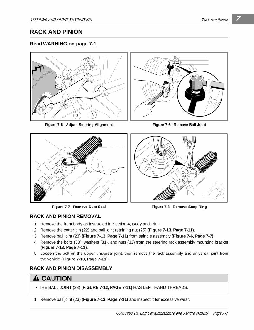
STEERING AND FRONT SUSPENSION Rack and Pinion
7
RACK AND PINION
Read WARNING on page 7-1.
RACK AND PINION REMOVAL 1. Remove the front body as instructed in Section 4, Body and Trim.
2. Remove the cotter pin (22) and ball joint retaining nut (25) (Figure 7-13, Page 7-11) .
3. Remove ball joint (23) (Figure 7-13, Page 7-11) from spindle assembly (Figure 7-6, Page 7-7) .
4. Remove the bolts (30), washers (31), and nuts (32) from the steering rack assembly mounting bracket(Figure 7-13, Page 7-11).
5. Loosen the bolt on the upper universal joint, then remove the rack assembly and universal joint fromthe vehicle (Figure 7-13, Page 7-11) .
RACK AND PINION DISASSEMBLY
1. Remove ball joint (23) (Figure 7-13, Page 7-11) and inspect it for excessive wear.
Figure 7-5 Adjust Steering Alignment Figure 7-6 Remove Ball Joint
Figure 7-7 Remove Dust Seal Figure 7-8 Remove Snap Ring
• THE BALL JOINT (23) (FIGURE 7-13, PAGE 7-11) HAS LEFT HAND THREADS.
2 3
CAUTION
1998/1999 DS Golf Car Maintenance and Service Manual Page 7-7
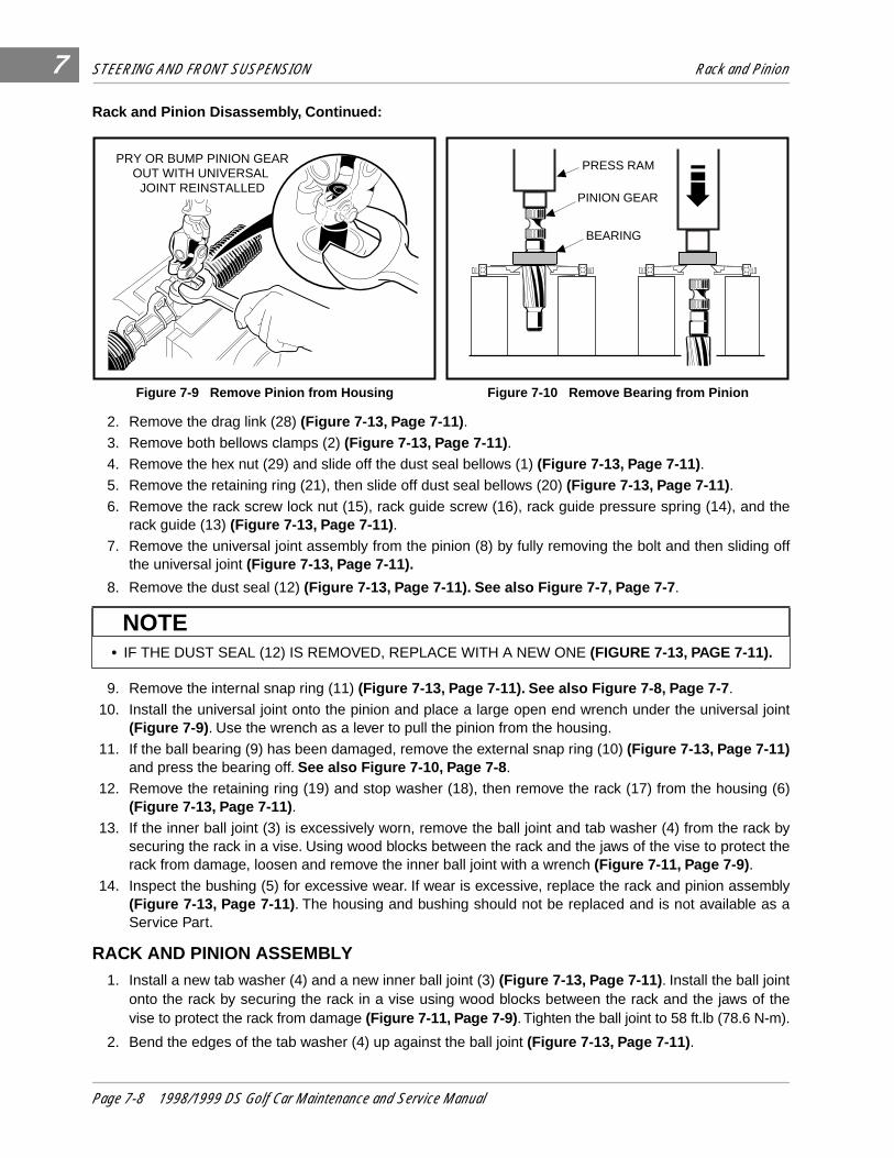
STEERING AND FRONT SUSPENSION Rack and Pinion
7
Rack and Pinion Disassembly, Continued:
2. Remove the drag link (28) (Figure 7-13, Page 7-11) .
3. Remove both bellows clamps (2) (Figure 7-13, Page 7-11) .
4. Remove the hex nut (29) and slide off the dust seal bellows (1) (Figure 7-13, Page 7-11) .
5. Remove the retaining ring (21), then slide off dust seal bellows (20) (Figure 7-13, Page 7-11) .
6. Remove the rack screw lock nut (15), rack guide screw (16), rack guide pressure spring (14), and therack guide (13) (Figure 7-13, Page 7-11) .
7. Remove the universal joint assembly from the pinion (8) by fully removing the bolt and then sliding offthe universal joint (Figure 7-13, Page 7-11).
8. Remove the dust seal (12) (Figure 7-13, Page 7-11). See also Figure 7-7, Page 7-7 .
9. Remove the internal snap ring (11) (Figure 7-13, Page 7-11). See also Figure 7-8, Page 7-7 .
10. Install the universal joint onto the pinion and place a large open end wrench under the universal joint(Figure 7-9) . Use the wrench as a lever to pull the pinion from the housing.
11. If the ball bearing (9) has been damaged, remove the external snap ring (10) (Figure 7-13, Page 7-11)and press the bearing off. See also Figure 7-10, Page 7-8 .
12. Remove the retaining ring (19) and stop washer (18), then remove the rack (17) from the housing (6)(Figure 7-13, Page 7-11) .
13. If the inner ball joint (3) is excessively worn, remove the ball joint and tab washer (4) from the rack bysecuring the rack in a vise. Using wood blocks between the rack and the jaws of the vise to protect therack from damage, loosen and remove the inner ball joint with a wrench (Figure 7-11, Page 7-9) .
14. Inspect the bushing (5) for excessive wear. If wear is excessive, replace the rack and pinion assembly(Figure 7-13, Page 7-11) . The housing and bushing should not be replaced and is not available as aService Part.
RACK AND PINION ASSEMBLY 1. Install a new tab washer (4) and a new inner ball joint (3) (Figure 7-13, Page 7-11) . Install the ball joint
onto the rack by securing the rack in a vise using wood blocks between the rack and the jaws of thevise to protect the rack from damage (Figure 7-11, Page 7-9) . Tighten the ball joint to 58 ft.lb (78.6 N-m).
2. Bend the edges of the tab washer (4) up against the ball joint (Figure 7-13, Page 7-11) .
Figure 7-9 Remove Pinion from Housing Figure 7-10 Remove Bearing from Pinion
• IF THE DUST SEAL (12) IS REMOVED, REPLACE WITH A NEW ONE (FIGURE 7-13, PAGE 7-11).
PRY OR BUMP PINION GEAROUT WITH UNIVERSAL
JOINT REINSTALLED
PRESS RAM
PINION GEAR
BEARING
NOTE
Page 7-8 1998/1999 DS Golf Car Maintenance and Service Manual
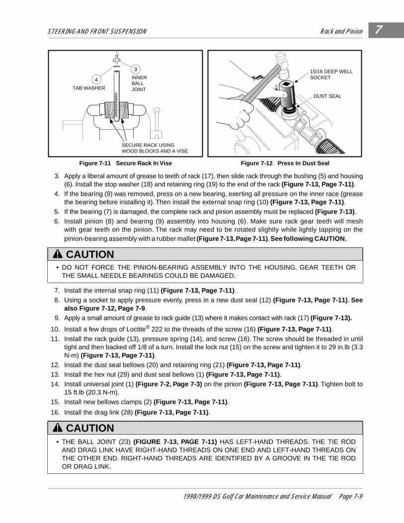
STEERING AND FRONT SUSPENSION Rack and Pinion 7
3. Apply a liberal amount of grease to teeth of rack (17), then slide rack through the bushing (5) and housing(6). Install the stop washer (18) and retaining ring (19) to the end of the rack (Figure 7-13, Page 7-11) .
4. If the bearing (9) was removed, press on a new bearing, exerting all pressure on the inner race (greasethe bearing before installing it). Then install the external snap ring (10) (Figure 7-13, Page 7-11) .
5. If the bearing (7) is damaged, the complete rack and pinion assembly must be replaced (Figure 7-13) .
6. Install pinion (8) and bearing (9) assembly into housing (6). Make sure rack gear teeth will meshwith gear teeth on the pinion. The rack may need to be rotated slightly while lightly tapping on thepinion-bearing assembly with a rubber mallet (Figure 7-13, Page 7-11) . See following CAUTION.
7. Install the internal snap ring (11) (Figure 7-13, Page 7-11) .
8. Using a socket to apply pressure evenly, press in a new dust seal (12) (Figure 7-13, Page 7-11) . Seealso Figure 7-12, Page 7-9 .
9. Apply a small amount of grease to rack guide (13) where it makes contact with rack (17) (Figure 7-13).
10. Install a few drops of Loctite® 222 to the threads of the screw (16) (Figure 7-13, Page 7-11) .
11. Install the rack guide (13), pressure spring (14), and screw (16). The screw should be threaded in untiltight and then backed off 1/8 of a turn. Install the lock nut (15) on the screw and tighten it to 29 in.lb (3.3N-m) (Figure 7-13, Page 7-11) .
12. Install the dust seal bellows (20) and retaining ring (21) (Figure 7-13, Page 7-11) .
13. Install the hex nut (29) and dust seal bellows (1) (Figure 7-13, Page 7-11) .
14. Install universal joint (1) (Figure 7-2, Page 7-3) on the pinion (Figure 7-13, Page 7-11) . Tighten bolt to15 ft.lb (20.3 N-m).
15. Install new bellows clamps (2) (Figure 7-13, Page 7-11) .
16. Install the drag link (28) (Figure 7-13, Page 7-11) .
Figure 7-11 Secure Rack In Vise Figure 7-12 Press In Dust Seal
• DO NOT FORCE THE PINION-BEARING ASSEMBLY INTO THE HOUSING. GEAR TEETH ORTHE SMALL NEEDLE BEARINGS COULD BE DAMAGED.
• THE BALL JOINT (23) (FIGURE 7-13, PAGE 7-11) HAS LEFT-HAND THREADS. THE TIE RODAND DRAG LINK HAVE RIGHT-HAND THREADS ON ONE END AND LEFT-HAND THREADS ONTHE OTHER END. RIGHT-HAND THREADS ARE IDENTIFIED BY A GROOVE IN THE TIE RODOR DRAG LINK.
SECURE RACK USING WOOD BLOCKS AND A VISE
TAB WASHER
INNERBALLJOINT
3
4
DUST SEAL
15/16 DEEP WELLSOCKET
CAUTION
CAUTION
1998/1999 DS Golf Car Maintenance and Service Manual Page 7-9
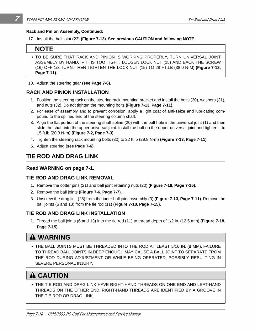
STEERING AND FRONT SUSPENSION Tie Rod and Drag Link7
Rack and Pinion Assembly, Continued:17. Install the ball joint (23) (Figure 7-13) . See previous CAUTION and following NOTE .
18. Adjust the steering gear (see Page 7-6).
RACK AND PINION INSTALLATION1. Position the steering rack on the steering rack mounting bracket and install the bolts (30), washers (31),
and nuts (32). Do not tighten the mounting bolts (Figure 7-13, Page 7-11) .
2. For ease of assembly and to prevent corrosion, apply a light coat of anti-seize and lubricating com-pound to the splined end of the steering column shaft.
3. Align the flat portion of the steering shaft spline (20) with the bolt hole in the universal joint (1) and thenslide the shaft into the upper universal joint. Install the bolt on the upper universal joint and tighten it to15 ft.lb (20.3 N-m) (Figure 7-2, Page 7-3) .
4. Tighten the steering rack mounting bolts (30) to 22 ft.lb (29.8 N-m) (Figure 7-13, Page 7-11) .
5. Adjust steering (see Page 7-6) .
TIE ROD AND DRAG LINK
Read WARNING on page 7-1.
TIE ROD AND DRAG LINK REMOVAL1. Remove the cotter pins (21) and ball joint retaining nuts (20) (Figure 7-18, Page 7-15) .
2. Remove the ball joints (Figure 7-6, Page 7-7) .
3. Unscrew the drag link (28) from the inner ball joint assembly (3) (Figure 7-13, Page 7-11) . Remove theball joints (6 and 13) from the tie rod (11) (Figure 7-18, Page 7-15) .
TIE ROD AND DRAG LINK INSTALLATION1. Thread the ball joints (6 and 13) into the tie rod (11) to thread depth of 1/2 in. (12.5 mm) (Figure 7-18,
Page 7-15).
• TO BE SURE THAT RACK AND PINION IS WORKING PROPERLY, TURN UNIVERSAL JOINTASSEMBLY BY HAND. IF IT IS TOO TIGHT, LOOSEN LOCK NUT (15) AND BACK THE SCREW(16) OFF 1/8 TURN. THEN TIGHTEN THE LOCK NUT (15) TO 28 FT.LB (38.0 N-M) (Figure 7-13,Page 7-11).
• THE BALL JOINTS MUST BE THREADED INTO THE ROD AT LEAST 5/16 IN. (8 MM). FAILURETO THREAD BALL JOINTS IN DEEP ENOUGH MAY CAUSE A BALL JOINT TO SEPARATE FROMTHE ROD DURING ADJUSTMENT OR WHILE BEING OPERATED, POSSIBLY RESULTING INSEVERE PERSONAL INJURY.
• THE TIE ROD AND DRAG LINK HAVE RIGHT-HAND THREADS ON ONE END AND LEFT-HANDTHREADS ON THE OTHER END. RIGHT-HAND THREADS ARE IDENTIFIED BY A GROOVE INTHE TIE ROD OR DRAG LINK.
NOTE
WARNING
CAUTION
Page 7-10 1998/1999 DS Golf Car Maintenance and Service Manual
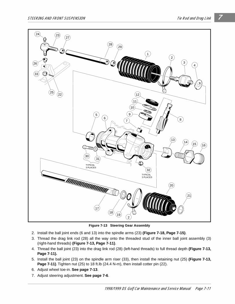
STEERING AND FRONT SUSPENSION Tie Rod and Drag Link 7
2. Install the ball joint ends (6 and 13) into the spindle arms (23) (Figure 7-18, Page 7-15) .
3. Thread the drag link rod (28) all the way onto the threaded stud of the inner ball joint assembly (3)(right-hand threads) (Figure 7-13, Page 7-11) .
4. Thread the ball joint (23) into the drag link rod (28) (left-hand threads) to full thread depth (Figure 7-13,Page 7-11).
5. Install the ball joint (23) on the spindle arm riser (33), then install the retaining nut (25) (Figure 7-13,Page 7-11). Tighten nut (25) to 18 ft.lb (24.4 N-m), then install cotter pin (22).
6. Adjust wheel toe-in. See page 7-13 .
7. Adjust steering adjustment. See page 7-6 .
Figure 7-13 Steering Gear Assembly
24 2327
28
26
2522
29
12
34
12
11
10
9
7
5
8
1314
15 16
32
3031
6
1718
19
21
TYPICAL3 PLACES
TYPICAL3 PLACES
2
20
33
1998/1999 DS Golf Car Maintenance and Service Manual Page 7-11
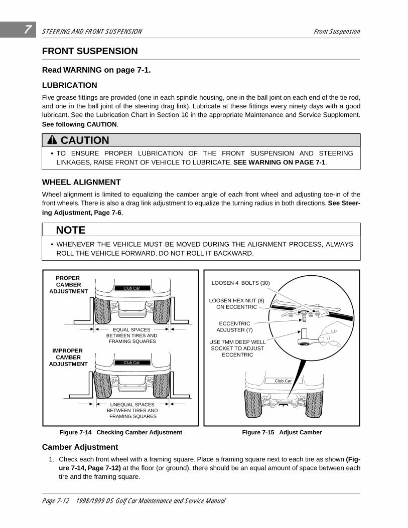
STEERING AND FRONT SUSPENSION Front Suspension7
FRONT SUSPENSION
Read WARNING on page 7-1.
LUBRICATIONFive grease fittings are provided (one in each spindle housing, one in the ball joint on each end of the tie rod,and one in the ball joint of the steering drag link). Lubricate at these fittings every ninety days with a goodlubricant. See the Lubrication Chart in Section 10 in the appropriate Maintenance and Service Supplement.See following CAUTION .
WHEEL ALIGNMENTWheel alignment is limited to equalizing the camber angle of each front wheel and adjusting toe-in of thefront wheels. There is also a drag link adjustment to equalize the turning radius in both directions. See Steer-ing Adjustment, Page 7-6 .
Camber Adjustment1. Check each front wheel with a framing square. Place a framing square next to each tire as shown (Fig-
ure 7-14, Page 7-12) at the floor (or ground), there should be an equal amount of space between eachtire and the framing square.
• TO ENSURE PROPER LUBRICATION OF THE FRONT SUSPENSION AND STEERINGLINKAGES, RAISE FRONT OF VEHICLE TO LUBRICATE. SEE WARNING ON PAGE 7-1 .
• WHENEVER THE VEHICLE MUST BE MOVED DURING THE ALIGNMENT PROCESS, ALWAYSROLL THE VEHICLE FORWARD. DO NOT ROLL IT BACKWARD.
Figure 7-14 Checking Camber Adjustment Figure 7-15 Adjust Camber
CAUTION
NOTE
Club Car
Club Car
EQUAL SPACES BETWEEN TIRES AND FRAMING SQUARES
UNEQUAL SPACES BETWEEN TIRES AND FRAMING SQUARES
PROPER CAMBER
ADJUSTMENT
IMPROPER CAMBER
ADJUSTMENT
Club Car
LOOSEN 4 BOLTS (30)
LOOSEN HEX NUT (8)ON ECCENTRIC
ECCENTRICADJUSTER (7)
USE 7MM DEEP WELLSOCKET TO ADJUST
ECCENTRIC
Page 7-12 1998/1999 DS Golf Car Maintenance and Service Manual
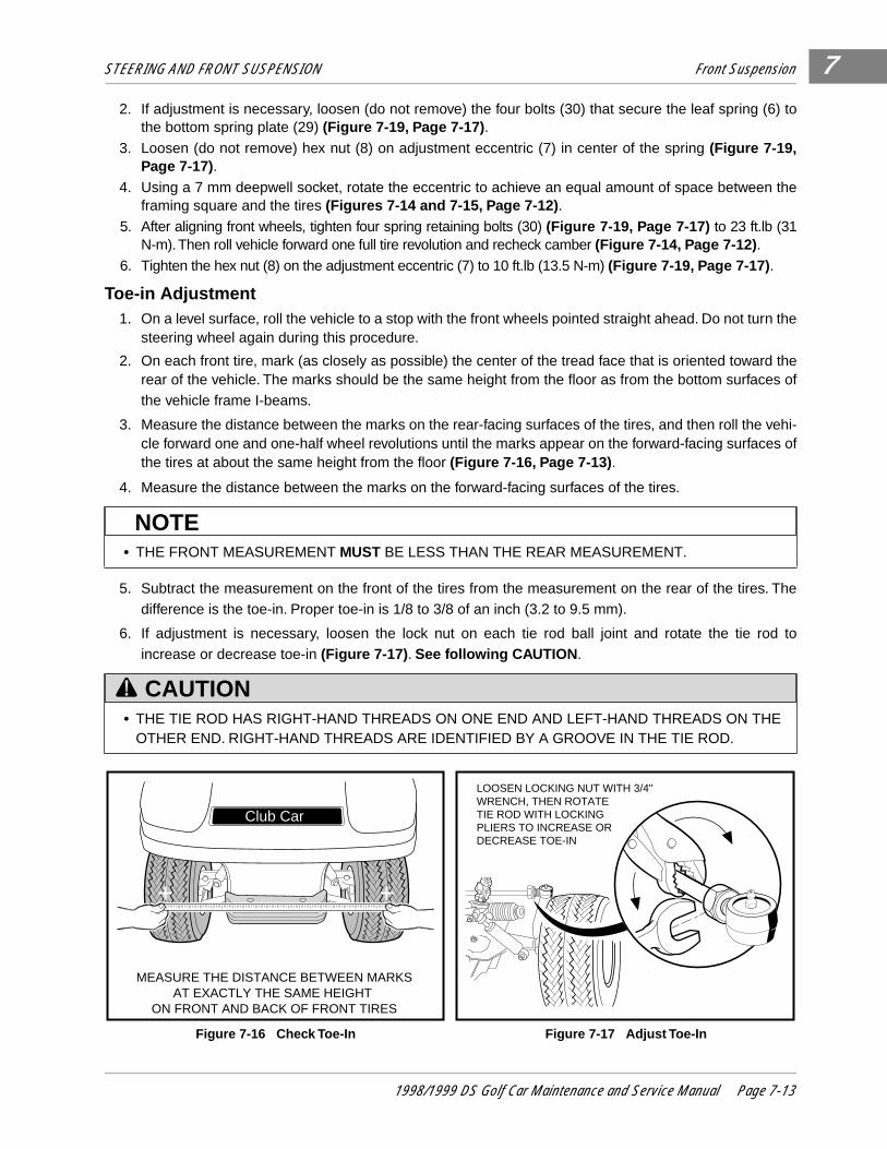
STEERING AND FRONT SUSPENSION Front Suspension 7
2. If adjustment is necessary, loosen (do not remove) the four bolts (30) that secure the leaf spring (6) tothe bottom spring plate (29) (Figure 7-19, Page 7-17) .
3. Loosen (do not remove) hex nut (8) on adjustment eccentric (7) in center of the spring (Figure 7-19,Page 7-17).
4. Using a 7 mm deepwell socket, rotate the eccentric to achieve an equal amount of space between theframing square and the tires (Figures 7-14 and 7-15, Page 7-12) .
5. After aligning front wheels, tighten four spring retaining bolts (30) (Figure 7-19, Page 7-17) to 23 ft.lb (31N-m). Then roll vehicle forward one full tire revolution and recheck camber (Figure 7-14, Page 7-12) .
6. Tighten the hex nut (8) on the adjustment eccentric (7) to 10 ft.lb (13.5 N-m) (Figure 7-19, Page 7-17) .
Toe-in Adjustment1. On a level surface, roll the vehicle to a stop with the front wheels pointed straight ahead. Do not turn the
steering wheel again during this procedure.
2. On each front tire, mark (as closely as possible) the center of the tread face that is oriented toward therear of the vehicle. The marks should be the same height from the floor as from the bottom surfaces ofthe vehicle frame I-beams.
3. Measure the distance between the marks on the rear-facing surfaces of the tires, and then roll the vehi-cle forward one and one-half wheel revolutions until the marks appear on the forward-facing surfaces ofthe tires at about the same height from the floor (Figure 7-16, Page 7-13) .
4. Measure the distance between the marks on the forward-facing surfaces of the tires.
5. Subtract the measurement on the front of the tires from the measurement on the rear of the tires. Thedifference is the toe-in. Proper toe-in is 1/8 to 3/8 of an inch (3.2 to 9.5 mm).
6. If adjustment is necessary, loosen the lock nut on each tie rod ball joint and rotate the tie rod toincrease or decrease toe-in (Figure 7-17) . See following CAUTION .
• THE FRONT MEASUREMENT MUST BE LESS THAN THE REAR MEASUREMENT.
• THE TIE ROD HAS RIGHT-HAND THREADS ON ONE END AND LEFT-HAND THREADS ON THEOTHER END. RIGHT-HAND THREADS ARE IDENTIFIED BY A GROOVE IN THE TIE ROD.
Figure 7-16 Check Toe-In Figure 7-17 Adjust Toe-In
NOTE
CAUTION
Club Car
MEASURE THE DISTANCE BETWEEN MARKSAT EXACTLY THE SAME HEIGHT
ON FRONT AND BACK OF FRONT TIRES
LOOSEN LOCKING NUT WITH 3/4" WRENCH, THEN ROTATE TIE ROD WITH LOCKING PLIERS TO INCREASE ORDECREASE TOE-IN
1998/1999 DS Golf Car Maintenance and Service Manual Page 7-13
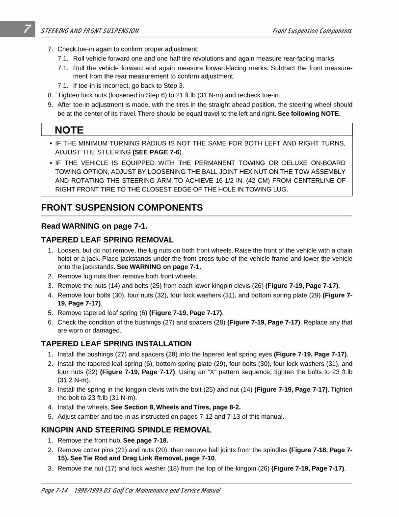
STEERING AND FRONT SUSPENSION Front Suspension Components7
7. Check toe-in again to confirm proper adjustment.7.1. Roll vehicle forward one and one half tire revolutions and again measure rear-facing marks.
7.1. Roll the vehicle forward and again measure forward-facing marks. Subtract the front measure-ment from the rear measurement to confirm adjustment.
7.1. If toe-in is incorrect, go back to Step 3.
8. Tighten lock nuts (loosened in Step 6) to 21 ft.lb (31 N-m) and recheck toe-in.
9. After toe-in adjustment is made, with the tires in the straight ahead position, the steering wheel shouldbe at the center of its travel. There should be equal travel to the left and right. See following NOTE.
FRONT SUSPENSION COMPONENTS
Read WARNING on page 7-1.
TAPERED LEAF SPRING REMOVAL1. Loosen, but do not remove, the lug nuts on both front wheels. Raise the front of the vehicle with a chain
hoist or a jack. Place jackstands under the front cross tube of the vehicle frame and lower the vehicleonto the jackstands. See WARNING on page 7-1.
2. Remove lug nuts then remove both front wheels.
3. Remove the nuts (14) and bolts (25) from each lower kingpin clevis (26) (Figure 7-19, Page 7-17) .
4. Remove four bolts (30), four nuts (32), four lock washers (31), and bottom spring plate (29) (Figure 7-19, Page 7-17).
5. Remove tapered leaf spring (6) (Figure 7-19, Page 7-17) .
6. Check the condition of the bushings (27) and spacers (28) (Figure 7-19, Page 7-17) . Replace any thatare worn or damaged.
TAPERED LEAF SPRING INSTALLATION1. Install the bushings (27) and spacers (28) into the tapered leaf spring eyes (Figure 7-19, Page 7-17) .
2. Install the tapered leaf spring (6), bottom spring plate (29), four bolts (30), four lock washers (31), andfour nuts (32) (Figure 7-19, Page 7-17) . Using an “X” pattern sequence, tighten the bolts to 23 ft.lb(31.2 N-m).
3. Install the spring in the kingpin clevis with the bolt (25) and nut (14) (Figure 7-19, Page 7-17) . Tightenthe bolt to 23 ft.lb (31 N-m).
4. Install the wheels. See Section 8, Wheels and Tires, page 8-2.5. Adjust camber and toe-in as instructed on pages 7-12 and 7-13 of this manual.
KINGPIN AND STEERING SPINDLE REMOVAL1. Remove the front hub. See page 7-18.2. Remove cotter pins (21) and nuts (20), then remove ball joints from the spindles (Figure 7-18, Page 7-
15). See Tie Rod and Drag Link Removal, page 7-10 .
3. Remove the nut (17) and lock washer (18) from the top of the kingpin (26) (Figure 7-19, Page 7-17) .
• IF THE MINIMUM TURNING RADIUS IS NOT THE SAME FOR BOTH LEFT AND RIGHT TURNS,ADJUST THE STEERING (SEE PAGE 7-6).
• IF THE VEHICLE IS EQUIPPED WITH THE PERMANENT TOWING OR DELUXE ON-BOARDTOWING OPTION, ADJUST BY LOOSENING THE BALL JOINT HEX NUT ON THE TOW ASSEMBLYAND ROTATING THE STEERING ARM TO ACHIEVE 16-1/2 IN. (42 CM) FROM CENTERLINE OFRIGHT FRONT TIRE TO THE CLOSEST EDGE OF THE HOLE IN TOWING LUG.
NOTE
Page 7-14 1998/1999 DS Golf Car Maintenance and Service Manual
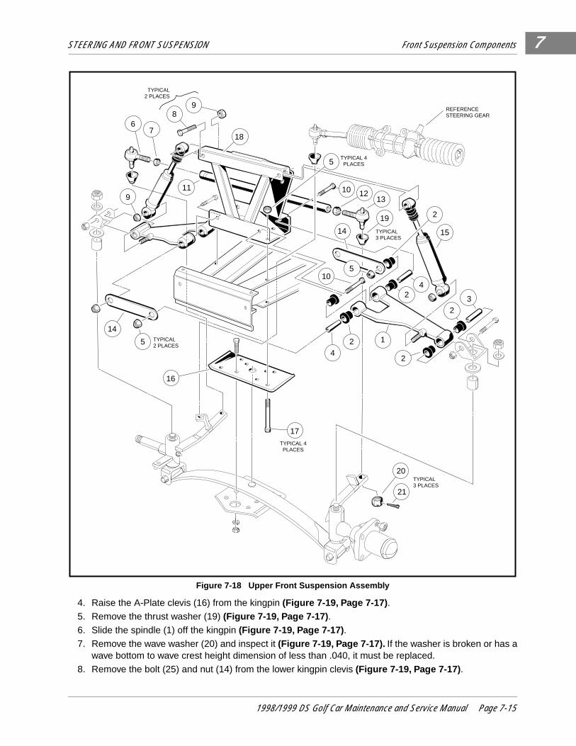
STEERING AND FRONT SUSPENSION Front Suspension Components 7
4. Raise the A-Plate clevis (16) from the kingpin (Figure 7-19, Page 7-17) .
5. Remove the thrust washer (19) (Figure 7-19, Page 7-17) .
6. Slide the spindle (1) off the kingpin (Figure 7-19, Page 7-17) .
7. Remove the wave washer (20) and inspect it (Figure 7-19, Page 7-17). If the washer is broken or has awave bottom to wave crest height dimension of less than .040, it must be replaced.
8. Remove the bolt (25) and nut (14) from the lower kingpin clevis (Figure 7-19, Page 7-17) .
Figure 7-18 Upper Front Suspension Assembly
9
4
12
2
2
24
15
3
14
13
18
1210
76
11
17TYPICAL 4PLACES
9
14
REFERENCESTEERING GEAR
20
21
TYPICAL3 PLACES
19
TYPICAL3 PLACES
5
105
2
TYPICAL2 PLACES
TYPICAL2 PLACES
5TYPICAL 4PLACES
16
8
1998/1999 DS Golf Car Maintenance and Service Manual Page 7-15
STEERING AND FRONT SUSPENSION Front Suspension Components7
Kingpin and Steering Removal, Continued:9. Remove the kingpin.
10. Inspect the kingpin and spindle. If either is worn or damaged, it must be replaced.
11. Inspect the bushings (3 and 4) (Figure 7-19, Page 7-17) . If the bushings are worn or damaged, removethem and press in new ones. See following NOTE .
KINGPIN AND STEERING SPINDLE INSTALLATION1. Inspect all parts and replace them as necessary.
2. Install the kingpin (26) over the tapered leaf spring eye. Insert the bolt (25) and install the nut (14) (Fig-ure 7-19, Page 7-17) . Tighten the bolt to 23 ft.lb (31 N-m).
3. Install the wave washer (20) on the kingpin (Figure 7-19, Page 7-17).4. Install the steering spindle on the kingpin. Then install the thrust washer (19), A-Plate clevis (16), flat
washer (18), and nut (17). Tighten the nut to 40 ft.lb (54.2 N-m) (Figure 7-19, Page 7-17) .
5. Attach the ball joints to the spindle arms, install and tighten the nut (20), and install the cotter pin (21)(Figure 7-18, Page 7-15) .
6. Install the front hub and wheel. See page 7-18.
DELTA A-PLATE REMOVAL1. Remove the wheel and tire.
2. Remove the bolts (10), A-Plate straps (14), and nuts (5) (Figure 7-18, Page 7-15) .
3. Remove the lower shock absorber mounting nut (9), then slide the shock absorber free of the Delta A-Plate (Figure 7-18, Page 7-15) .
4. Remove the Delta A-Plate (1) (Figure 7-18, Page 7-15) .
5. Inspect the bushings (2) in the Delta A-Plate and replace them if necessary.
DELTA A-PLATE INSTALLATION1. Install the A-Plate in reverse order of removal. Tighten the A-Plate suspension bolts (10 and 24) to 20
ft.lb (27.1 N-m) (Figure 7-18, Page 7-15) .
2. Tighten shock absorber mounting nut (9) to 20 ft.lb (27.1 Nm).
3. Install the wheel and adjust the camber as instructed on page 7-12 of this manual.
SHOCK ABSORBER REMOVAL1. Inspect the shock absorbers for fluid leakage at the point where the shaft enters the shock absorber
body. Leaking shock absorbers should be replaced.
2. Remove the nut (9) attaching the shock absorber to the A-Plate (Figure 7-18, Page 7-15) .
3. Remove nut (9) and bolt (8) attaching shock absorber to the vehicle frame (Figure 7-18, Page 7-15) .
4. Remove the shock absorber.
SHOCK ABSORBER INSTALLATION1. Install the shock absorber by reversing the removal procedure.
2. Tighten the nuts to 20 ft.lb (27 N-m).
• IF BUSHINGS ARE REPLACED, REAM NEW BUSHINGS TO .750 -.752 IN. (19.05/19.10 MM) INDIAMETER. REAMER SHOULD BE LONG ENOUGH TO REAM BOTH BUSHINGS FROM ONEDIRECTION.
NOTE
Page 7-16 1998/1999 DS Golf Car Maintenance and Service Manual
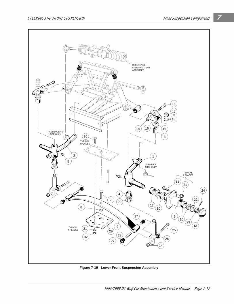
STEERING AND FRONT SUSPENSION Front Suspension Components 7
Figure 7-19 Lower Front Suspension Assembly
PASSENGER'SSIDE ONLY
15
17
18
19
3
16
TYPICAL4 PLACES
1
DRIVER'SSIDE ONLY
2
5
7
4
20
1121
TYPICAL4 PLACES
22
24
1210
910
2313
27
25
26
14
8
31
32
6
2928
27
REFERENCESTEERING GEARASSEMBLY
30TYPICAL
4 PLACES
14
1998/1999 DS Golf Car Maintenance and Service Manual Page 7-17
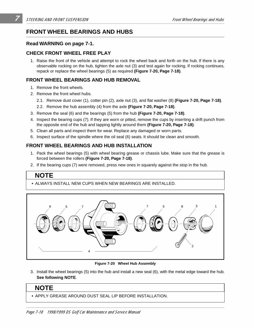
STEERING AND FRONT SUSPENSION Front Wheel Bearings and Hubs7
FRONT WHEEL BEARINGS AND HUBS
Read WARNING on page 7-1.
CHECK FRONT WHEEL FREE PLAY1. Raise the front of the vehicle and attempt to rock the wheel back and forth on the hub. If there is any
observable rocking on the hub, tighten the axle nut (3) and test again for rocking. If rocking continues,repack or replace the wheel bearings (5) as required (Figure 7-20, Page 7-18) .
FRONT WHEEL BEARINGS AND HUB REMOVAL1. Remove the front wheels.
2. Remove the front wheel hubs.
2.1. Remove dust cover (1), cotter pin (2), axle nut (3), and flat washer (8) (Figure 7-20, Page 7-18) .
2.2. Remove the hub assembly (4) from the axle (Figure 7-20, Page 7-18) .
3. Remove the seal (6) and the bearings (5) from the hub (Figure 7-20, Page 7-18) .
4. Inspect the bearing cups (7). If they are worn or pitted, remove the cups by inserting a drift punch fromthe opposite end of the hub and tapping lightly around them (Figure 7-20, Page 7-18) .
5. Clean all parts and inspect them for wear. Replace any damaged or worn parts.
6. Inspect surface of the spindle where the oil seal (6) seats. It should be clean and smooth.
FRONT WHEEL BEARINGS AND HUB INSTALLATION1. Pack the wheel bearings (5) with wheel bearing grease or chassis lube. Make sure that the grease is
forced between the rollers (Figure 7-20, Page 7-18) .
2. If the bearing cups (7) were removed, press new ones in squarely against the stop in the hub.
3. Install the wheel bearings (5) into the hub and install a new seal (6), with the metal edge toward the hub.See following NOTE .
• ALWAYS INSTALL NEW CUPS WHEN NEW BEARINGS ARE INSTALLED.
Figure 7-20 Wheel Hub Assembly
• APPLY GREASE AROUND DUST SEAL LIP BEFORE INSTALLATION.
NOTE
6 5 7 7 5 8 3 1
2
4
NOTE
Page 7-18 1998/1999 DS Golf Car Maintenance and Service Manual

STEERING AND FRONT SUSPENSION Front Wheel Bearings and Hubs 7
4. Install the hub assembly (4) and flat washer (8) on the axle and start the axle nut (3).5. Tighten the axle nut until the hub is hard to turn, then back the nut off until the hub turns freely. Installthe cotter pin (2) (Figure 7-20, Page 7-18) .
6. Install the dust cap (1) (Figure 7-20, Page 7-18) .
7. Repeat the procedure for the opposite wheel. Install the wheels and then tighten the lug nuts to 55 ft.lb(74.6 N-m).
• WHEN THE COTTER PINS ARE BENT OVER, MAKE SURE THEY DO NOT CONTACT THE HUBOR DUST CAP.
NOTE
1998/1999 DS Golf Car Maintenance and Service Manual Page 7-19

7
8
SECTION 8–WHEELS AND TIRES
GENERAL INFORMATION
Maximum tire life and good vehicle handling qualities are directly related to proper wheel and tire care.
• Keep tires inflated to 12-14 psi (83-96 kPa) for gasoline vehicles; 18-20 psi (124-138 kPa) for electricvehicles.
• ONLY TRAINED MECHANICS SHOULD REPAIR OR SERVICE THIS VEHICLE. ANYONE DOINGEVEN SIMPLE REPAIRS OR SERVICE SHOULD HAVE KNOWLEDGE AND EXPERIENCE INGENERAL ELECTRICAL AND MECHANICAL REPAIR.
• FOLLOW ALL PROCEDURES EXACTLY AS STATED IN THIS MANUAL, AND HEED ALLDANGER, WARNING, AND CAUTION STATEMENTS LISTED IN THIS MANUAL AS WELL ASTHOSE AFFIXED TO THE VEHICLE.
• ALWAYS WEAR SAFETY GLASSES OR APPROVED EYE PROTECTION WHILE SERVICINGVEHICLE. WEAR A FULL FACE SHIELD WHEN WORKING WITH BATTERIES.
• MOVING PARTS! - DO NOT ATTEMPT TO SERVICE THE VEHICLE WHILE IT IS RUNNING.• USE INSULATED TOOLS WHEN WORKING NEAR BATTERIES OR ELECTRICAL
CONNECTIONS.• LIFT ONLY ONE END OF VEHICLE AT A TIME. BEFORE LIFTING, LOCK BRAKES AND CHOCK
THE WHEELS THAT REMAIN ON THE FLOOR. USE A SUITABLE LIFTING DEVICE (CHAINHOIST OR HYDRAULIC FLOOR JACK) WITH 1000 LBS. (454 KG.) MINIMUM LIFTING CAPACITY.DO NOT USE THE LIFTING DEVICE TO HOLD VEHICLE IN RAISED POSITION. ALWAYS USEAPPROVED JACKSTANDS OF PROPER WEIGHT CAPACITY TO SUPPORT THE VEHICLE.
• TURN KEY SWITCH OFF, PLACE FORWARD/REVERSE HANDLE IN NEUTRAL , REMOVE KEY,CHOCK WHEELS, AND DISCONNECT THE BATTERY(IES) BEFORE SERVICING THE VEHICLE.
GASOLINE VEHICLES ONLY:
• TO AVOID UNINTENTIONALLY STARTING THE VEHICLE:
- DISCONNECT BATTERY CABLES, NEGATIVE (-) FIRST (SECTION 1, FIGURE 1-1).
- DISCONNECT THE SPARK PLUG WIRE FROM THE SPARK PLUG.
• FRAME GROUND - DO NOT ALLOW TOOLS OR OTHER METAL OBJECTS TO CONTACTFRAME WHEN DISCONNECTING BATTERY CABLES OR OTHER ELECTRICAL WIRING. NEVERALLOW A POSITIVE WIRE TO TOUCH THE VEHICLE FRAME, ENGINE, OR OTHER METALCOMPONENT.
ELECTRIC VEHICLES ONLY:
• TO AVOID UNINTENTIONALLY STARTING THE VEHICLE, DISCONNECT BATTERIES AS SHOWN(SECTION 1, FIGURES 1-2 OR 1-3).
• ON POWERDRIVE PLUS VEHICLES, PLACE THE TOW SWITCH IN THE TOW POSITIONBEFORE DISCONNECTING BATTERIES.
• ON POWERDRIVE SYSTEM 48 VEHICLES, DISCHARGE THE CONTROLLER AS FOLLOWSAFTER DISCONNECTING THE BATTERIES:
- TURN THE KEY SWITCH TO ON AND PLACE THE FORWARD/REVERSE HANDLE IN THEREVERSE POSITION.
- SLOWLY DEPRESS THE ACCELERATOR PEDAL AND KEEP IT DEPRESSED UNTIL THEREVERSE WARNING BUZZER CAN NO LONGER BE HEARD. WHEN THE BUZZER STOPSSOUNDING, THE CONTROLLER IS DISCHARGED.
WARNING
1998/1999 DS Golf Car Maintenance and Service Manual Page 8-1
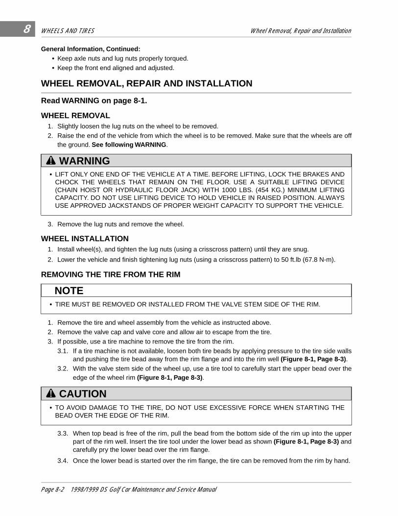
WHEELS AND TIRES Wheel Removal, Repair and Installation
8
General Information, Continued:• Keep axle nuts and lug nuts properly torqued.
• Keep the front end aligned and adjusted.
WHEEL REMOVAL, REPAIR AND INSTALLATION
Read WARNING on page 8-1.
WHEEL REMOVAL1. Slightly loosen the lug nuts on the wheel to be removed.
2. Raise the end of the vehicle from which the wheel is to be removed. Make sure that the wheels are offthe ground. See following WARNING .
3. Remove the lug nuts and remove the wheel.
WHEEL INSTALLATION1. Install wheel(s), and tighten the lug nuts (using a crisscross pattern) until they are snug.
2. Lower the vehicle and finish tightening lug nuts (using a crisscross pattern) to 50 ft.lb (67.8 N-m).
REMOVING THE TIRE FROM THE RIM
1. Remove the tire and wheel assembly from the vehicle as instructed above.
2. Remove the valve cap and valve core and allow air to escape from the tire.
3. If possible, use a tire machine to remove the tire from the rim.
3.1. If a tire machine is not available, loosen both tire beads by applying pressure to the tire side wallsand pushing the tire bead away from the rim flange and into the rim well (Figure 8-1, Page 8-3) .
3.2. With the valve stem side of the wheel up, use a tire tool to carefully start the upper bead over theedge of the wheel rim (Figure 8-1, Page 8-3) .
3.3. When top bead is free of the rim, pull the bead from the bottom side of the rim up into the upperpart of the rim well. Insert the tire tool under the lower bead as shown (Figure 8-1, Page 8-3) andcarefully pry the lower bead over the rim flange.
3.4. Once the lower bead is started over the rim flange, the tire can be removed from the rim by hand.
• LIFT ONLY ONE END OF THE VEHICLE AT A TIME. BEFORE LIFTING, LOCK THE BRAKES ANDCHOCK THE WHEELS THAT REMAIN ON THE FLOOR. USE A SUITABLE LIFTING DEVICE(CHAIN HOIST OR HYDRAULIC FLOOR JACK) WITH 1000 LBS. (454 KG.) MINIMUM LIFTINGCAPACITY. DO NOT USE LIFTING DEVICE TO HOLD VEHICLE IN RAISED POSITION. ALWAYSUSE APPROVED JACKSTANDS OF PROPER WEIGHT CAPACITY TO SUPPORT THE VEHICLE.
• TIRE MUST BE REMOVED OR INSTALLED FROM THE VALVE STEM SIDE OF THE RIM.
• TO AVOID DAMAGE TO THE TIRE, DO NOT USE EXCESSIVE FORCE WHEN STARTING THEBEAD OVER THE EDGE OF THE RIM.
WARNING
NOTE
CAUTION
Page 8-2 1998/1999 DS Golf Car Maintenance and Service Manual
WHEELS AND TIRES Wheel Removal, Repair and Installation
8
REPAIRING A TIRE1. Determine the location and cause of the air leak:
1.1. Remove the wheel (see Wheel Removal) and inflate the tire to no more than 20 psi (138 kPa).
1.2. Immerse the tire in water and then mark the point where bubbles are formed by escaping air.
1.3. Determine the cause of the air leak. See following NOTE .
2. When the cause of the air leak has been determined, remove tire from the rim (see Tire Removal) andrepair as required.
INSTALLING THE TIRE ON THE RIM
1. Clean both tire beads to remove dirt or other foreign matter.
Figure 8-1 Removing Tire From The Rim
• AN AIR LEAK COULD BE DUE TO A PUNCTURED CASING, FAULTY VALVE CORE,IMPROPERLY SEATED VALVE STEM, OR IMPROPERLY SEATED TIRE BEAD.
• SMALL HOLES IN THE CASING CAN BE PLUGGED USING A STANDARD AUTOMOTIVETUBELESS TIRE REPAIR KIT AVAILABLE AT AUTO SUPPLY STORES.
• WHILE MOUNTING OR INFLATING TIRE, KEEP HANDS, FINGERS, ETC. FROM EXPOSEDAREAS BETWEEN THE TIRE BEAD AND RIM.
WITH TIRE DEFLATED,LOOSEN TIRE BEADSFROM RIM BY APPLYING PRESSURE TO TIRESIDE WALLS
ATIRE
BEADS
TIREBEADS
RIM FLANGE
VALVE STEM SIDE UP
PRESSURE AGAINSTTIRE TOOL
B
TIRE BEADSPOSITIONEDIN RIM WELL
USING TIRE TOOL,CAREFULLY LIFTTIRE BEAD OVERRIM FLANGE
C
LIFT LOWERTIRE BEADUP AND OVERRIM FLANGE
NOTE
WARNING
1998/1999 DS Golf Car Maintenance and Service Manual Page 8-3
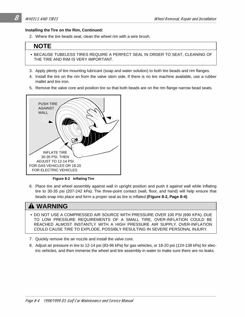
WHEELS AND TIRES Wheel Removal, Repair and Installation
8
Installing the Tire on the Rim, Continued:
2. Where the tire beads seat, clean the wheel rim with a wire brush.
3. Apply plenty of tire mounting lubricant (soap and water solution) to both tire beads and rim flanges.
4. Install the tire on the rim from the valve stem side. If there is no tire machine available, use a rubbermallet and tire iron.
5. Remove the valve core and position tire so that both beads are on the rim flange narrow bead seats.
6. Place tire and wheel assembly against wall in upright position and push it against wall while inflatingtire to 30-35 psi (207-242 kPa). The three-point contact (wall, floor, and hand) will help ensure thatbeads snap into place and form a proper seal as tire is inflated (Figure 8-2, Page 8-4) .
7. Quickly remove the air nozzle and install the valve core.
8. Adjust air pressure in tire to 12-14 psi (83-96 kPa) for gas vehicles, or 18-20 psi (124-138 kPa) for elec-tric vehicles, and then immerse the wheel and tire assembly in water to make sure there are no leaks.
• BECAUSE TUBELESS TIRES REQUIRE A PERFECT SEAL IN ORDER TO SEAT, CLEANING OFTHE TIRE AND RIM IS VERY IMPORTANT.
Figure 8-2 Inflating Tire
• DO NOT USE A COMPRESSED AIR SOURCE WITH PRESSURE OVER 100 PSI (690 KPA). DUETO LOW PRESSURE REQUIREMENTS OF A SMALL TIRE, OVER-INFLATION COULD BEREACHED ALMOST INSTANTLY WITH A HIGH PRESSURE AIR SUPPLY. OVER-INFLATIONCOULD CAUSE TIRE TO EXPLODE, POSSIBLY RESULTING IN SEVERE PERSONAL INJURY.
NOTE
PUSH TIRE AGAINSTWALL
INFLATE TIRE30-35 PSI, THEN
ADJUST TO 12-14 PSIFOR GAS VEHICLES OR 18-20
FOR ELECTRIC VEHICLES
WARNING
Page 8-4 1998/1999 DS Golf Car Maintenance and Service Manual
9
SECTION 9–REAR SUSPENSION
GENERAL INFORMATION
The rear suspension of the DS vehicle is completely independent. It consists of two leaf springs controlled bytwo shock absorbers mounted between the springs and the vehicle frame.
• ONLY TRAINED MECHANICS SHOULD REPAIR OR SERVICE THIS VEHICLE. ANYONE DOINGEVEN SIMPLE REPAIRS OR SERVICE SHOULD HAVE KNOWLEDGE AND EXPERIENCE INGENERAL ELECTRICAL AND MECHANICAL REPAIR.
• FOLLOW ALL PROCEDURES EXACTLY AS STATED IN THIS MANUAL, AND HEED ALLDANGER, WARNING, AND CAUTION STATEMENTS LISTED IN THIS MANUAL AS WELL ASTHOSE AFFIXED TO THE VEHICLE.
• ALWAYS WEAR SAFETY GLASSES OR APPROVED EYE PROTECTION WHILE SERVICINGVEHICLE. WEAR A FULL FACE SHIELD WHEN WORKING WITH BATTERIES.
• MOVING PARTS! - DO NOT ATTEMPT TO SERVICE THE VEHICLE WHILE IT IS RUNNING.
• USE INSULATED TOOLS WHEN WORKING NEAR BATTERIES OR ELECTRICALCONNECTIONS.
• LIFT ONLY ONE END OF THE VEHICLE AT A TIME. BEFORE LIFTING, LOCK THE BRAKES ANDCHOCK THE WHEELS THAT REMAIN ON THE FLOOR. USE A SUITABLE LIFTING DEVICE(CHAIN HOIST OR HYDRAULIC FLOOR JACK) WITH 1000 LBS. (454 KG.) MINIMUM LIFTINGCAPACITY. DO NOT USE LIFTING DEVICE TO HOLD VEHICLE IN RAISED POSITION. ALWAYSUSE APPROVED JACKSTANDS OF PROPER WEIGHT CAPACITY TO SUPPORT THE VEHICLE.
• TURN KEY SWITCH OFF, PLACE FORWARD/REVERSE HANDLE IN NEUTRAL , REMOVE KEY,CHOCK THE WHEELS, AND DISCONNECT BATTERY(IES) BEFORE SERVICING VEHICLE.
GASOLINE VEHICLES ONLY:
• TO AVOID UNINTENTIONALLY STARTING THE VEHICLE:
- DISCONNECT BATTERY CABLES, NEGATIVE (-) FIRST (FIGURE 1-1, SECTION 1).- DISCONNECT THE SPARK PLUG WIRE FROM THE SPARK PLUG.
• FRAME GROUND - DO NOT ALLOW TOOLS OR OTHER METAL OBJECTS TO CONTACTFRAME WHEN DISCONNECTING BATTERY CABLES OR OTHER ELECTRICAL WIRING. NEVERALLOW A POSITIVE WIRE TO TOUCH THE VEHICLE FRAME, ENGINE, OR OTHER METALCOMPONENT.
ELECTRIC VEHICLES ONLY:
• TO AVOID UNINTENTIONALLY STARTING THE VEHICLE, DISCONNECT BATTERIES AS SHOWNIN SECTION 1, FIGURES 1-2 OR 1-3.
• ON POWERDRIVE PLUS VEHICLES, PLACE THE TOW SWITCH IN THE TOW POSITIONBEFORE DISCONNECTING BATTERIES.
• ON POWERDRIVE SYSTEM 48 VEHICLES, DISCHARGE THE CONTROLLER AS FOLLOWSAFTER DISCONNECTING THE BATTERIES:
- TURN THE KEY SWITCH TO ON AND PLACE THE FORWARD/REVERSE HANDLE IN THEREVERSE POSITION.
- SLOWLY DEPRESS THE ACCELERATOR PEDAL AND KEEP IT DEPRESSED UNTIL THEREVERSE WARNING BUZZER CAN NO LONGER BE HEARD. WHEN THE BUZZER STOPSSOUNDING, THE CONTROLLER IS DISCHARGED.
WARNING
1998/1999 DS Golf Car Maintenance and Service Manual Page 9-1

REAR SUSPENSION General Information
9
Figure 9-1 Rear Suspension Assembly and Mounting
4
3
3
15
151
2
43
4
4
2
15
TYPICAL 2PLACES
9
10
10
9
5
6
8
7121
4
2
14
13
16
TYPICAL ONEACH SIDE
OF VEHICLE
17
11
17
BRAKE CABLEHANGER MOUNTING
GASOLINE VEHICLE ONLY
BRAKE CABLEHANGER MOUNTING
ELECTRIC VEHICLE ONLY
TYPICAL ONEACH SIDE
OF VEHICLE
Page 9-2 1998/1999 DS Golf Car Maintenance and Service Manual
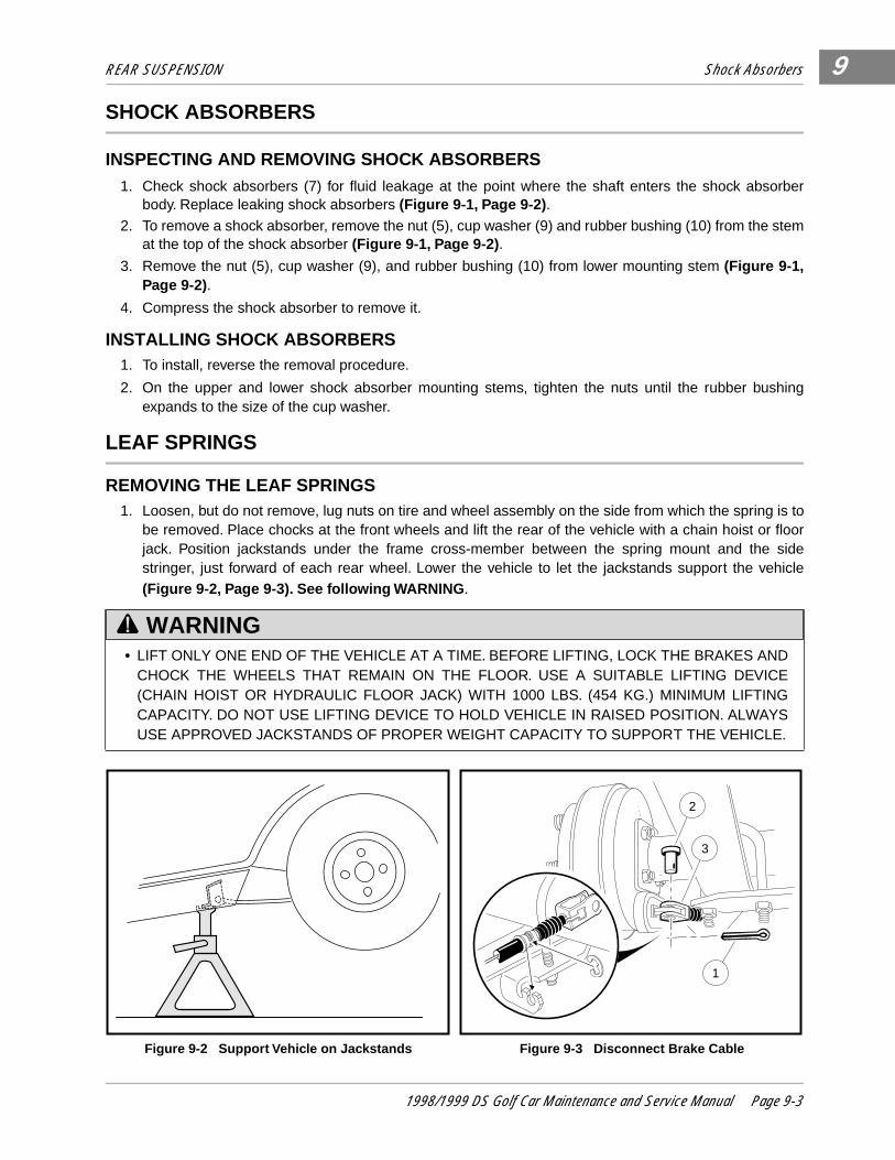
REAR SUSPENSION Shock Absorbers
9
SHOCK ABSORBERS
INSPECTING AND REMOVING SHOCK ABSORBERS1. Check shock absorbers (7) for fluid leakage at the point where the shaft enters the shock absorber
body. Replace leaking shock absorbers (Figure 9-1, Page 9-2) .
2. To remove a shock absorber, remove the nut (5), cup washer (9) and rubber bushing (10) from the stemat the top of the shock absorber (Figure 9-1, Page 9-2) .
3. Remove the nut (5), cup washer (9), and rubber bushing (10) from lower mounting stem (Figure 9-1,Page 9-2).
4. Compress the shock absorber to remove it.
INSTALLING SHOCK ABSORBERS1. To install, reverse the removal procedure.
2. On the upper and lower shock absorber mounting stems, tighten the nuts until the rubber bushingexpands to the size of the cup washer.
LEAF SPRINGS
REMOVING THE LEAF SPRINGS1. Loosen, but do not remove, lug nuts on tire and wheel assembly on the side from which the spring is to
be removed. Place chocks at the front wheels and lift the rear of the vehicle with a chain hoist or floorjack. Position jackstands under the frame cross-member between the spring mount and the sidestringer, just forward of each rear wheel. Lower the vehicle to let the jackstands support the vehicle(Figure 9-2, Page 9-3). See following WARNING .
• LIFT ONLY ONE END OF THE VEHICLE AT A TIME. BEFORE LIFTING, LOCK THE BRAKES ANDCHOCK THE WHEELS THAT REMAIN ON THE FLOOR. USE A SUITABLE LIFTING DEVICE(CHAIN HOIST OR HYDRAULIC FLOOR JACK) WITH 1000 LBS. (454 KG.) MINIMUM LIFTINGCAPACITY. DO NOT USE LIFTING DEVICE TO HOLD VEHICLE IN RAISED POSITION. ALWAYSUSE APPROVED JACKSTANDS OF PROPER WEIGHT CAPACITY TO SUPPORT THE VEHICLE.
Figure 9-2 Support Vehicle on Jackstands Figure 9-3 Disconnect Brake Cable
WARNING
1
2
3
1998/1999 DS Golf Car Maintenance and Service Manual Page 9-3
REAR SUSPENSION Leaf Springs
9
Removing the Leaf Springs, Continued:
2. Place a floorjack under the transaxle differential casing to support (but not lift) the drivetrain. Raise itjust enough to relieve tension on the shock absorbers without compressing them.
3. Remove the tire and wheel assembly on the side from which the spring is to be removed.
4. Remove the cotter pin (1) and the clevis pin (2) at the brake lever and brake cable connection and pullthe clevis (3) away from the lever (Figure 9-3, Page 9-3) . Detach the brake cable from the shock mountbracket (16) (Figure 9-1, Page 9-2).
5. Remove the nut (5), cup washer (9), and rubber bushing (10) from the lower mounting stem of theshock absorber (Figure 9-1, Page 9-2) .
6. Remove the nuts (14), lock washers (13), and the U-bolt (11) securing the spring to the transaxle (Fig-ure 9-1, Page 9-2) . Remove the shock mount bracket (16) and the U-bolt.
7. Remove the bolt (15) and nut (2) attaching the rear spring to the shackle (1) (Figure 9-1, Page 9-2) .
8. Remove the nut (2) and bolt (15) attaching the front of the spring to the vehicle frame (Figure 9-1,Page 9-2) and remove the spring.
9. Inspect the bushings (4) and spacers (3) in the spring eyes and replace them if they are worn or dam-aged (Figure 9-1, Page 9-2) .
INSTALLING THE LEAF SPRINGS1. To install the springs, reverse the removal procedure. See following CAUTION .
2. Tighten the nuts on the U-bolts to 25 ft.lb (34 N-m).
3. Tighten nylon locknuts (2) on spring mounting bolts (15) to 15 ft.lb (20.3 N-m) (Figure 9-1, Page 9-2) .
• WHEN POSITIONING THE SPRING ON THE TRANSAXLE, BE SURE TO INSERT THE LOCATINGBOLT ON THE SPRING IN THE LOCATING HOLE IN THE TRANSAXLE SADDLE.
CAUTION
Page 9-4 1998/1999 DS Golf Car Maintenance and Service Manual


Golf CarsClub Car Inc.P.O. Box 204658Augusta, GA 30917-4658