Embed Size (px)
Citation preview

Abstract—The monograph analysis a low power voltage
controlled ring oscillator, implement using the 1P6M 0.18µm CMOS process provided by TSMC with 1.8 volts power supply. The circuit is a modification of conventional ring oscillator. A tail current improvement is applied to reduce the charging and discharging time. The output frequency ranges from 0.958-4.43 GHz with control voltages of 1 V to 1.8 V. The simulated result of the phase noise is –94.5 dBc/Hz @ 1 MHz. The circuit draws 0.212 mW of power at Vtail = Vctrl = 1V and 0.226 mW at Vtail = Vctrl = 1.8 V from the 1.8 V supply.
Indexed Terms—CMOS, low power, phase noise, tail current and voltage controlled oscillator (VCO).
I. INTRODUCTION The VCO is the key component that controls the
frequency of the PLL. A good VCO should have low phase noise low DC power and high frequency swing. There are mainly two types of VCO, ring oscillator and LC tank. LC oscillators have low phase noise and as well as low frequency swing. They are used in wireless communication applications. On the other hand ring oscillators have wide range of frequency swing and easy to implement. Ring oscillators also occupy less chip area as they do not have inductor as compared to LC tank oscillators but they are more prone to noise.
A three stage ring oscillator is designed using 1P6M 0.18µm CMOS technology provided by TSMC.
The circuit achieves RF frequency range by using the tail current improvement. The first delay cell is a CMOS NAND gate and the other two delay cells are CMOS inverters.
The tail current improvement is applied to the first delay cell, CMOS NAND gate. The tail current improvement reduces the charging and discharging time of the output node capacitance of the particular delay cell. As the charging and discharging time reduces the output frequency increases. The inputs of the first delay cell are control voltage and the output feedback.
The output frequency varies from 0.958 GHz to 4.43 GHz at Vtail = Vctrl = 1 V and Vtail = Vctrl = 1.8 V respectively. The objective of this paper is to achieve good noise performance and low DC power consumption with RF frequency range. Vtail is tail current controlling voltage and Vctrl is to control and tune the voltage.
Manuscript received August 26, 2011; revised November 5, 2011. Authors are with Department of Electronics and Communications
Engineering, National Institute of Technology,Jalandhar, India (e-mail: [email protected],[email protected]).
II. PROPOSED RING OSCILLATOR
A. Tail Current Improvement
Fig. 1. Tail current improvement [1]
The tail current improvement is shown in figure 1[1]. The transistor M3 is added to the source of transistor M2 where transistor M1 and M2 both are acting as a CMOS inverter. Transistor M3 is acting as a current source when in saturation. The input impedance of an ideal current source is infinite. Thus when Vin < Vt, M1, M2 is turned off and M1 is turned on, output node capacitance CL is charging by VDD through M1 where M3 provides better isolation. This reduces the charging time of output node capacitance as compared to normal inverter case. Vt represents the threshold voltage of particular transistor.
For the discharging time improvement when Vin > Vt, M2, M2 is turned on and M1 is turned off, output node capacitance is discharging to ground through M2 and M3 where M3 provide discharging current as soon as M2 gets on and M1 gets off. This initial discharging current reduces the discharging time of the output node capacitance CL.
B. Ring oscillator Circuit and Design The schematic of the proposed ring oscillator is shown in
figure 2. The first delay is CMOS Nand gate and the other two are CMOS inverters. The tail current improvement is applied to the first delay cell. The first delay cell Nand gate will act as an inverter if both of its inputs are the same. This completes the three inverter stages. Each inverter has a certain delay between stages. This delay is termed as ‘inverter pair delay’. It is the sum of the rise and fall time of an individual inverter.
For N stage ring oscillator the oscillation frequency is given by as:
(1)
1P6M 0.18-µm Low Power CMOS Ring Oscillator for Radio Frequency Applications
Ashish Raman and R. K. Sarin
International Journal of Computer Theory and Engineering, Vol. 3, No. 6, December 2011
770

Fig. 2. Schematic for the proposed ring oscillator
where τrise and τfall are the rise and fall time of a individual delay cell or stage. For a good VCRO rise time and fall time should be equal. Thus taking τrise = τfall = τ. As a 3 stage ring oscillator is presented in this paper so by taking the value N=3, the frequency of oscillation is given as:
Fosc = 1/6 τ (2)
For a inverter shown in figure 3[2], the (W/L) ratios of the transistors (nMOS and pMOS) are given as :
Fig. 3. CMOS inverter [2]
, , , , 1 (3)
, , , , 1 (4)
where Cload is the output load capacitance and Cox is the gate oxide capacitance per unit area. Again taking τrise = τfall = τ, eq. 3 and 4 will be as:
, , , , 1
(5)
, , , , 1 (6)
Clearly as µp<µn, the (W/L)p will be greater than (W/L)n.
C. Phase Noise Analysis Phase noise performance of ring oscillator is poorer than
LC resonator based oscillator [1]. Phase error introduced by noise impulses is highest at the waveform rising and falling edges where energy is being pushed into or pulled from the load capacitors. In case of LC oscillator the capacitor charge is not completely removed per cycle but in case of ring oscillator complete charging and discharging of the node capacitance is occurred. Thus phase noise performance of ring oscillator is poorer than LC oscillators. Figure 4[1] shows the amplitude and phase noise on oscillator signal.
Fig. 4. Amplitude and phase noise on oscillator signal[1]
Analysis has shown that single ended ring oscillators exhibit a relatively constant amount of phase noise independent of the number of stages N for a given frequency and power consumption [1]:
∆ (7)
where PDC is the DC power consumption and ΔF is an offset frequency close to the oscillator frequency.
International Journal of Computer Theory and Engineering, Vol. 3, No. 6, December 2011
771
Vol
tage
(Vol
ts)
Vol
tage
(Vol
ts)
D. Power Analysis The static power consumption of the CMOS inverter is
quite negligible. During switching events where the output load capacitance alternatively charged and discharged, the CMOS inverter consumes power [2].
Considering figure 5 and assuming that the input is an ideal voltage waveform with negligible rise and fall time.
Fig. 5. CMOS inverter for power analysis [2]
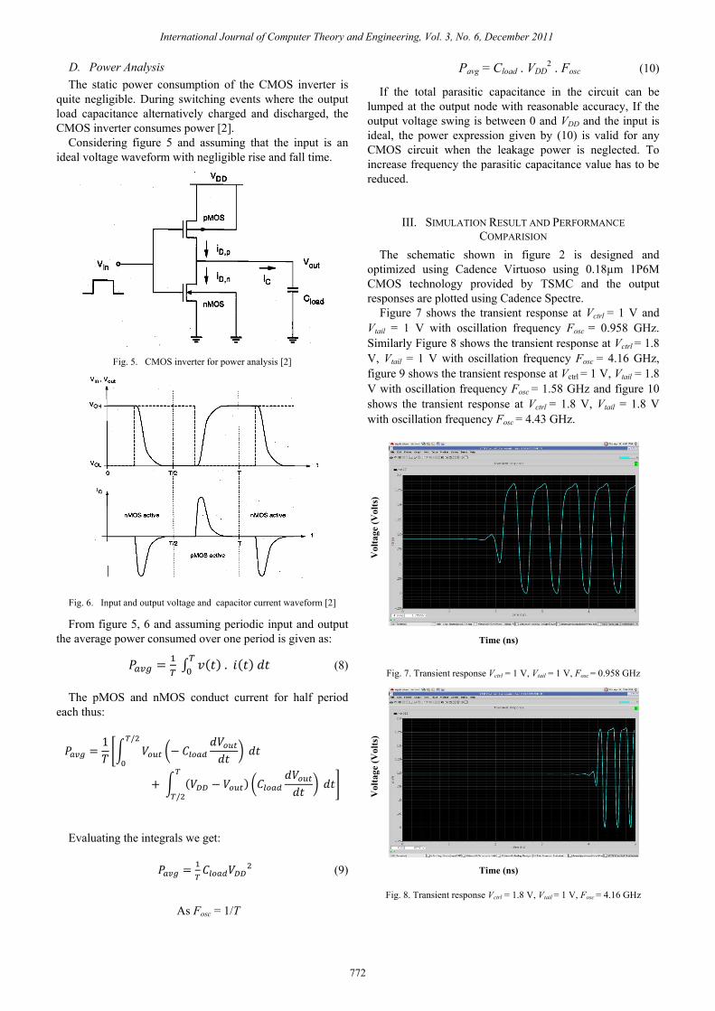
Fig. 6. Input and output voltage and capacitor current waveform [2]
From figure 5, 6 and assuming periodic input and output the average power consumed over one period is given as: . (8)
The pMOS and nMOS conduct current for half period each thus: 1 /
/
Evaluating the integrals we get: (9)
As Fosc = 1/T
Pavg = Cload . VDD2 . Fosc (10)
If the total parasitic capacitance in the circuit can be lumped at the output node with reasonable accuracy, If the output voltage swing is between 0 and VDD and the input is ideal, the power expression given by (10) is valid for any CMOS circuit when the leakage power is neglected. To increase frequency the parasitic capacitance value has to be reduced.
III. SIMULATION RESULT AND PERFORMANCE COMPARISION
The schematic shown in figure 2 is designed and optimized using Cadence Virtuoso using 0.18µm 1P6M CMOS technology provided by TSMC and the output responses are plotted using Cadence Spectre.
Figure 7 shows the transient response at Vctrl = 1 V and Vtail = 1 V with oscillation frequency Fosc = 0.958 GHz. Similarly Figure 8 shows the transient response at Vctrl = 1.8 V, Vtail = 1 V with oscillation frequency Fosc = 4.16 GHz, figure 9 shows the transient response at Vctrl = 1 V, Vtail = 1.8 V with oscillation frequency Fosc = 1.58 GHz and figure 10 shows the transient response at Vctrl = 1.8 V, Vtail = 1.8 V with oscillation frequency Fosc = 4.43 GHz.
Fig. 7. Transient response Vctrl = 1 V, Vtail = 1 V, Fosc = 0.958 GHz
Fig. 8. Transient response Vctrl = 1.8 V, Vtail = 1 V, Fosc = 4.16 GHz
Time (ns)
Time (ns)
International Journal of Computer Theory and Engineering, Vol. 3, No. 6, December 2011
772

Volta
ge (V
olts
)
Vol
tage
(Vol
ts)
Phas
e N
oise
dB
c/H
z @
1 M
Hz
Phas
e N
oise
dB
c/H
z @
1 M
Hz
Phas
e N
oise
dB
c/H
z @
1 M
Hz
Fig. 9. Transient response Vctrl =1 V, Vtail=1.8 V, Fosc = 1.58 GHz
Time (ns)
Fig. 10. Transient response Vctrl =1.8 V, Vtail=1.8 V, Fosc = 4.43 GHz
Fig. 11. Transient response Vctrl = 1 V, Vtail = 1 V, PN = -83.77 dBc/Hz @ 1 MHz
Figure 11 shows the noise response at Vctrl = 1 V and Vtail = 1 V with phase noise -83.77 dBc/Hz @ 1 MHz. Similarly Figure 12 shows the noise response at Vctrl = 1.8 V, Vtail = 1 V with phase noise -94.23 dBc/Hz @ 1 MHz, figure 13 at Vctrl = 1 V, Vtail = 1.8 V with phase noise -90.84 dBc/Hz @ 1 MHz and figure 14 at Vctrl = 1.8 V, Vtail = 1.8 V with phase noise value -94.51 dBc/Hz @ 1 MHz.
Frequency vs control voltage graph is shown in figure 15 where red line is for Vtail=1.8 V and black for Vtail = 1 V.
Performance comparison is given in table 1, where it is shown that the power consumption is least in this work.
Fig. 12. Transient response Vctrl = 1.8 V, Vtail = 1 V, PN = -94.23 dBc/Hz @
1 MHz
Fig. 13. Transient response Vctrl = 1 V, Vtail = 1.8 V, PN = -94.51 dBc/Hz @ 1 MHz
Fig. 14. Transient response Vctrl = 1.8 V, Vtail = 1.8 V, PN = -94.51 dBc/Hz @ 1 MHz
Fig. 15. Oscillation frequency variation with control voltage
Time (ns)
Frequency (GHz)
Frequency (GHz)
Frequency (GHz) Frequency (GHz)
International Journal of Computer Theory and Engineering, Vol. 3, No. 6, December 2011
773

TABLE I: PERFORMANCE COMPARISON
Reference Process Technology(µm)
Type Tuning Range (GHz) Power (mW)
Phase Noise dBc/Hz @ 1 MHz
Supply Voltage (Volts)
[3] 0.18 CMOS Ring
1.624-3.229 1 - 1.8
[4] 0.18 CMOS Ring
8.4-10.1 50 -99.9 1.8
[5] 0.18 CMOS Differential 4.85-4.93 - -124.9 1.8
[6] 0.18 CMOS Armstrong VCO
4.96-5.34 3.9 -116.7 1.8
[7] 0.18 CMOS Colpitts VCO 4.9-5.46 6.4 -120.2 1.8
[8] 0.18 CMOS Hartley VCO 4.02-4.5 6.75 -122.5 1.8
[9] 0.25 CMOS LC
4.55-5.45 13.7 -114 1.8
[10] 0.18 CMOS Ring
5.16-5.93 27 -99.5 1.8
This Work 0.18 CMOS Ring
0.958-4.43 0.226 -94.51 1.8
IV. CONCLUSIONS In this work a 3 stage voltage controlled ring oscillator
is designed using 0.18µm 1P6M CMOS technology provided by TSMC which consumes a very low DC power, Pavg = 0.226 mW with a frequency range from 0.958 to 4.43 GHz. The phase noise of the circuit is –94.51 dBc/Hz @1 MHz.
REFERENCES [1] R. Caverly, “CMOS RFIC DESIGN PRINCIPLES,” ARTECH
HOUSE, London, 1st Edition,ch 6,pp 269-273, 2007. [2] S. M. Kang and Y. Leblebici, “CMOS Digital Integrated Circuits
Analysis and Design,” Tata McGraw Hill, Edition2003, ch 6,pp 231-261,nineteenth reprient 2008.
[3] H. M. Liu, X. X. Zhang, Y. j. Dai, Y. j. Lu, and B. l. Wei, “A Wide Range Low Power CMOS Radio Frequency Ring Oscillator,” 4th IEEE conference on Industrial Electronics and Applications, ICIEA ,pp. 1340 – 1344, 2009..
[4] Q. Hai, Liu, L. G. Wang, and Liter Siek, “A 0.18-µm 10-GHz CMOS Ring Oscillator for Optical Transceivers,” IEEE
International Symposium on Circuits and Systems, ISCAS, Vol. 2,pp 1525 - 1528, 2005.
[5] T. Nghia Nguyen and J. W. Lee, “Low Phase Noise Differential Vackar VCO in 0.18µm CMOS Technology,” IEEE Microwave and Wireless Components Letters Vol. 20 No. 02 February 2010.
[6] Y-H. Chung, S.-L. Jang, S.-H. Lee, R.-H. Yen, and J.-J. Jhao, “5 GHz low power current reuse balanced CMOS differential Armstrong VCO,” IEEE Microwave and Wireless Components Letters Vol. 17, No. 2, PP. 139–141, February 2007.
[7] J-A. Hou and Y.-H.Wang, “A 5 GHz differential Colpitts CMOS VCO using the bottom PMOS cross couple current source,” IEEE Microwave and Wireless Components Letters Vol. 19, No. 6, PP. 401–403, June 2009.
[8] S-H. Lee, Y.-H. Chuang, S.-L. Jang, and C.-C. Chen, “Low phase noise,” IEEE Microwave and Wireless Components Letters Vol. 17, No. 2, PP. 145–147, February 2007.
[9] C. Samori, S. Levantion, and V. Boccuzzi, “A -94 dBc/Hz @100 kHz fully-integrated, 5-GHz CMOS VCO with 18% tuning range for bluetooth applications,” in Proceedings IEEE Custom Integrated Circuits Conference, PP. 201–204, 2001.
[10] Y. A. Eken and J. P. Uyemura, “A 5.9-GHz voltage-controlled ring oscillator in 0.18-µm CMOS,” IEEE J. Solid-State Circuits, vol.39, No. 1, pp. 230-233, January 2004.
International Journal of Computer Theory and Engineering, Vol. 3, No. 6, December 2011
774


![Full page photo€¦ · 3.70 0.18 Õnsnà21_yuãunuaamÜFJ+FJanSnaàouuaouaaäu 0.06 uaìnmuuouïf[fapãu [cnn) rillsansfapãu (UT] 4.76 0.70 comp úuÜuuafañu [l_nnl o .30 0.18](https://img.pdfslide.net/doc/110x75/5f28ea5db7be101d2346532e/full-page-photo-370-018-nsn21yuunuaamoefjfjansnaouuaouaau-006-uanmuuouffapu.jpg)


![VERS L'INFINI ET AU-DELA [scale=0.18]afficheintro](https://img.pdfslide.net/doc/110x75/62b48d69cf94061aeb1eaece/vers-linfini-et-au-dela-scale018afficheintro.jpg)