Embed Size (px)
Citation preview

©2010 Cengage Learning
CHAPTER 4
APPLICATIONS OF BOOLEAN ALGEBRAMINTERM AND MAXTERM EXPANSIONS
This chapter in the book includes:ObjectivesStudy Guide
4.1 Conversion of English Sentences to Boolean Equations4.2 Combinational Logic Design Using a Truth Table4.3 Minterm and Maxterm Expansions4.4 General Minterm and Maxterm Expansions4.5 Incompletely Specified Functions4.6 Examples of Truth Table Construction4.7 Design of Binary Adders and Subtractors
Problems

©2010 Cengage Learning
Conversion of English Sentences to Boolean Equations
The three main steps in designing a single-output combinational switching circuit are
1. Find a switching function that specifies the desired behavior of the circuit.
2. Find a simplified algebraic expression for the function.
3. Realize the simplified function using available logic elements.
* 了解所需電路之指令要求 轉化為一布林函式 簡化並實現為邏輯電路

©2010 Cengage Learning
Example 1
F A B
We will define a two-valued variable to indicate the truth of falsity of each phrase:
F = 1 if “Mary watches TV” is true; otherwise F = 0.
A = 1 if “it is Monday night” is true; otherwise A = 0.
B = 1 if “she has finished her homework” is true; otherwise B = 0.
Because F is “true” if A and B are both “true”, we can represent the sentence by F = A • B

©2010 Cengage Learning
Example 2
The alarm will ring iff the alarm switch is turned on and the door is not closed, or it is after 6 P.M. and the window is not closed.
Define the desired function of a circuit

©2010 Cengage Learning
Example 2 (continued)
Section 4.1 (p. 91)
The corresponding equation is:
And the corresponding circuit is:
The alarm will ring iff the alarm switch is turned on and the door is not closed, or it is after 6 P.M. and the window is not closed.
Convert to Boolean Equation
Realize it to a logiccurcuit

©2010 Cengage Learning
4.2 Combinational Logic Design using a Truth Table
Suppose we want the output of a circuit to be f = 1 if N ≥ 0112 and f = 0 if N < 0112. Then the truth table is:
* 用 truth table 反推電路

©2010 Cengage Learning
Next, we will derive an algebraic expression for f from the truth table by using the combinations of values of A, B, and C for which f = 1. For example, the term A′BC is 1 only if A = 0, B = 1, and C = 1. Finding all terms such that f = 1 and ORing them together yields:
f = A′BC + AB′C′ + AB′C + ABC′ + ABC (4-1)
* 將布林函式以積之合 (SOP) 來表示

©2010 Cengage Learning
The equation can be simplified by first combining terms and then eliminating A′:
This equation leads directly to the following circuit:
f = A′BC + AB′ + AB = A′BC + A = A + BC (4-2)
簡化公式 11-D
* 簡化並實現其電路

©2010 Cengage Learning
Instead of writing f in terms of the 1’s of the function, we may also write f in terms of the 0’s of the function. Observe that the term A + B + C is 0 only if A = B = C = 0. ANDing all of these ‘0’ terms together yields:
f = (A + B + C)(A + B + C′)(A + B′ + C) (4-3)
• 反之,可以取 truth table 中之 0 項, 以布林函式合之積 (POS) 來表示

©2010 Cengage Learning
By combining terms and using the second distributive law, we can simplify the equation:
f = (A + B + C)(A + B + C′)(A + B′ + C) (4-3)
f = (A + B)(A + B′ + C) = A + B(B′ + C) = A + BC (4-4)簡化公式 (X+Y)(X+Z)=X+YZ

©2010 Cengage Learning
4.3 Minterm and Maxterm Expansions
Each of the terms in Equation (4-1) is referred to as a minterm. In general, a minterm of n variables is a product of n literals in which each variable appears exactly once in either true or complemented form, but not both.
(A literal is a variable or its complement)
f = A′BC + AB′C′ + AB′C + ABC′ + ABC (4-1)
• 函數之最小項 : 為一標準積之合 (standard SOP) 的表示式• 函數內之每一乘積項皆為一 minterm ,且其中之變數僅出 現一次。

©2010 Cengage Learning
Table 4-1 Minterms and Maxterms for Three Variables
©2010 Cengage Learning
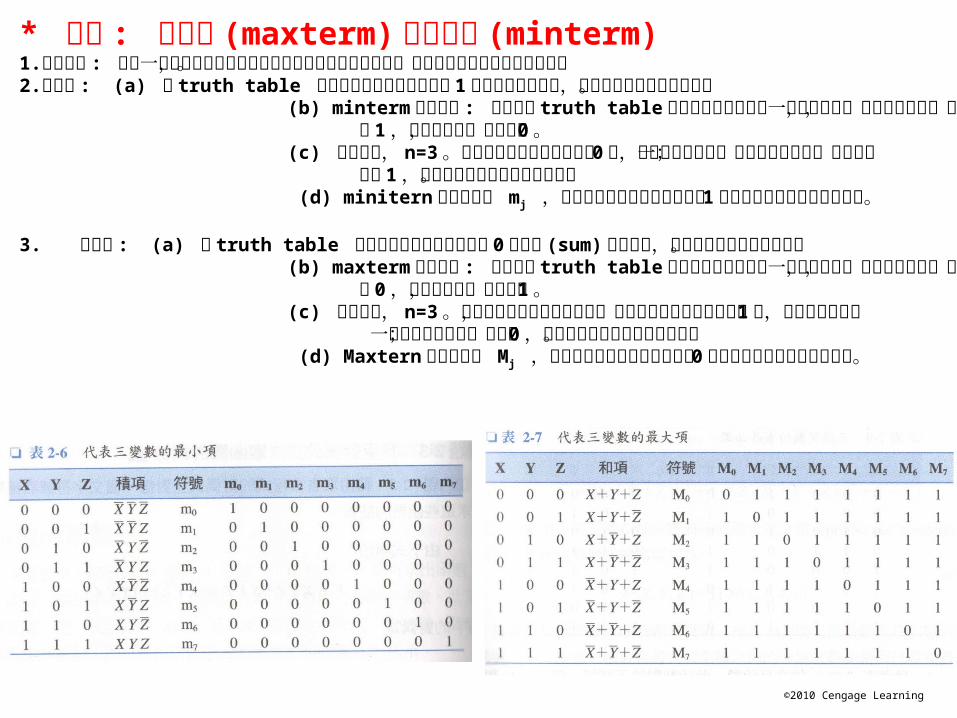
* 總結 : 最大項 (maxterm) 與最小項 (minterm)1.主要目的 : 提供一標準型式有助於布林表示式化簡程序的加速完成,且更適合實現邏輯電路之使用。2.最小項 : (a) 將 truth table 中所有代表函數二進位值為 1 的乘積項都找出來,即可得到最小項之表示式。 (b) minterm 的特點是 : 可以代表 truth table 中所有二進位變數的一個完整組合,對該組合而言,其值 為 1 ,其他組合時,其值則為 0 。 (c) 舉例來說, n=3 。如果二進位組合中的位元為 0 時,其文字符號便是一個取補數的變數;如果位元 值為 1 ,其文字符號則未取補數的變數。 (d) minitern 的代表符號 mj ,其下標代表可以使最小項值為 1 的二進位組合之等效十進位值。
3. 最大項 : (a) 將 truth table 中所有代表函數二進位值為 0 的和項 (sum) 都找出來,即可得到最大項之表示式。 (b) maxterm 的特點是 : 可以代表 truth table 中所有二進位變數的一個完整組合,對該組合而言,其值 為 0 ,其他組合時,其值則為 1 。 (c) 舉例來說, n=3 。最大項就是三變數之邏輯和,如果二進位組合中的位元為 1 時,其文字符號便是 一個取補數的變數;如果為 0 ,其文字符號則未取補數的變數。 (d) Maxtern 的代表符號 Mj ,其下標代表可以使最小項值為 0 的二進位組合之等效十進位值。

©2010 Cengage Learning
Minterm expansion for a function is unique. Equation (4-1) can be rewritten in terms of m-notation as:
This can be further abbreviated by listing only the decimal subscripts in the form:
f = A′BC + AB′C′ + AB′C + ABC′ + ABC(4-1)
f (A, B, C) = m3 + m4 + m5 + m6 + m7 (4-5)
f (A, B, C) = Ʃ m(3, 4, 5, 6, 7) (4-5)

©2010 Cengage Learning
Minterm Expansion Example
Find the minterm expansion of f(a,b,c,d) = a'(b' + d) + acd'.
* 如何取得函數之最小項表示式 ( 即轉成最簡化的積之合 )
每一最小項,不足之變數皆補上

©2010 Cengage Learning
Maxterm Expansion Example
Find the maxterm expansion of f(a,b,c,d) = a'(b' + d) + acd'.
* 如何取得函數之最大項表示式 ( 即轉成最簡化的合之積 )
• 最大項與最小項互為補數關係 ! f (A, B, C) = Ʃ m(3, 4, 5, 6, 7) f (A, B, C) = (0, 1, 2)
©2010 Cengage Learning
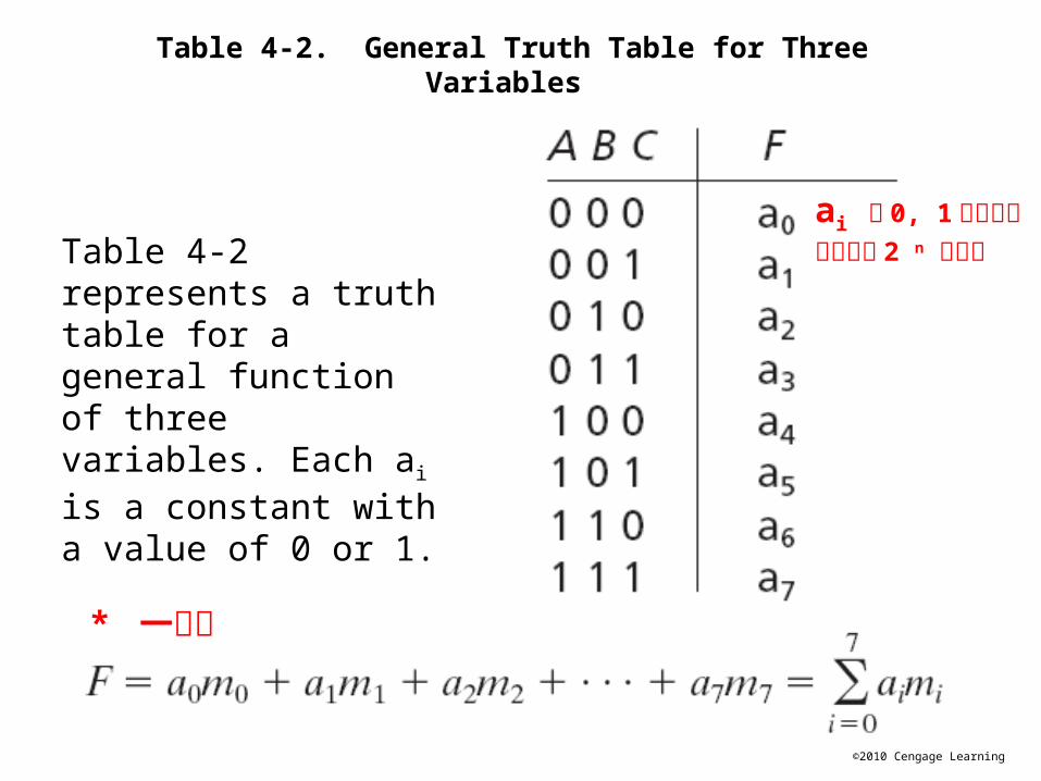
Table 4-2. General Truth Table for Three Variables
Table 4-2 represents a truth table for a general function of three variables. Each ai is a constant with a value of 0 or 1.
* 一般式
ai 有 0, 1 兩種可能全部會有 2 n 之表示

©2010 Cengage Learning
General Minterm and Maxterm Expansions
We can write the minterm expansion for a general function of three variables as follows:
The maxterm expansion for a general function of three variables is:

©2010 Cengage Learning
* 用 DeMorgan’s Law
* 最大項與最小項之補數表示式

©2010 Cengage Learning
Table 4-3. Conversion of Forms
Table 4-3 summarizes the procedures for conversion between minterm and maxterm expansions of F and F'

©2010 Cengage Learning
Table 4-4. Application of Table 4-3
互補關係
(4-12) (4-15) 可得證明 (4-13) (4-14)
(4-12) (4-14) 可得證明 (4-13)(4-15)

©2010 Cengage Learning
Product of Two minterm expansion:Only these with the same terms can
presented

©2010 Cengage Learning
Section 4.5 (p. 99)
Incompletely Specified Functions
A large digital system is usually divided into many subcircuits. Consider the following example in which the output of circuit N1 drives the input of circuit N2:

©2010 Cengage Learning
Table 4-5: Truth Table with Don't
Cares
Let us assume the output of N1 does not generate all possible combinations of values for A, B, and C. In particular, we will assume there are no combinations of values for w, x, y, and z which cause A, B, and C to assume values of 001 or 110.
Input (w, x, y, z ) don’t lead to ABC =001 or 110, then we say F is incompletely specified
Don’t-cares

©2010 Cengage Learning
When we realize the function, we must specify values for the don’t-cares. It is desirable to choose values which will help simplify the function. If we assign the value 0 to both X’s, then
If we assign 1 to the first X and 0 to the second, then
If we assign 1 to both X’s, then
The second choice of values leads to the simplest solution.
So how to write a function with don’t-cares ?

©2010 Cengage Learning
Table 4-5The minterm expansion for Table 4-5 is:
The maxterm expansion for Table 4-5 is:
Write a function with don’t-care terms

©2010 Cengage Learning
Examples of Truth Table Construction
We will design a simple binary adder that adds two 1-bit binary numbers, a and b, to give a 2-bit sum. The numeric values for the adder inputs and outputs are as follows:

©2010 Cengage Learning
We will represent inputs to the adder by the logic variables A and B and the 2-bit sum by the logic variables X and Y, and we construct a truth table:
Because a numeric value of 0 is represented by a logic 0 and a numeric value of 1 by a logic 1, the 0’s and 1’s in the truth table are exactly the same as in the previous table. From the truth table,

©2010 Cengage Learning
Ex: Design an adder which adds two 2-bit binary numbers to give a 3-bit binary sum. Find the truth table for the circuit. The circuit has four inputs and three outputs as shown:
Example 01 : Design an adder

©2010 Cengage Learning
m0
m1
.
.

©2010 Cengage Learning
Example 02 : Design an error detector for 6-3-1-1 BCD code
See Page.21(Table 1-2)

©2010 Cengage Learning
Example 03 : Design an detector for 8-4-2-1 DCB, where input canbe exactly divisible by 3
0
3
6
Too many don’t-care terms We will treat this by Karnaugh-map

©2010 Cengage Learning
Example 4: Design of Binary Adders for 4-Bit Binary Numbers
We will design a parallel adder that adds two 4-bit unsigned binary numbers and a carry input to give a 4-bit sum and a carry output.
Ex.

©2010 Cengage Learning
One approach would be to construct a truth table with nine inputs and five outputs and then derive and simplify the five output equations.
A better method is to design a logic module that adds two bits and a carry, and then connect four of these modules together to form a 4-bit adder.
Methods

©2010 Cengage Learning
Parallel Adder Composed ofFour Full Adders Ex.

©2010 Cengage Learning
Truth Table for a Full Adder
進位到下一行他行進位過來

©2010 Cengage Learning
Full Adder Logic Equations
The logic equations for the full adder derived from the truth table are:
Ex. (X+X+X)=X

©2010 Cengage Learning
Implementation of Full Adder
However, when 2’s complement is used, the carrier(C4) is discarded, therefore no carry into
the first cell, C0 is 0.
So first cell can be simplified to

©2010 Cengage Learning
An overflow has occurred if adding two positive numbers gives a negative result or adding two negative numbers gives a positive result.
We define an overflow signal, V = 1 if an overflow occurs.For Figure 4-3, V = A3′B3′S3 + A3B3S3′
Detect Overflow for Signed Binary Numbers
A3 B3 S3 V0100010

©2010 Cengage LearningFigure 4-6: Binary Subtracter Using Full Adders
Full Adders may be used to form A – B using the 2’s complement representation for negative numbers. The 2’s complement of B can be formed by first finding the 1’s complement and then adding 1.
Example 5: Design of Binary subtracter for 4-Bit Binary Numbers(see HW 1.33)

©2010 Cengage Learning
Figure 4-7: Parallel Subtracter
Alternatively, direct subtraction can be accomplished by employing a full subtracter in a manner analogous to a full adder.
有無借出 ? 需要借入 ?

©2010 Cengage Learning
Table 4.6. Truth Table for Binary Full Subtracter
有無借出 ? 需要借入 ?

©2010 Cengage Learning
Consider xi = 0, yi = 1, and bi = 1:
Section 4.7 (p. 107)需要借入

©2010 Cengage Learning
HW Chapter 4:
4.5 (a)4.74.134.224.33