Embed Size (px)
Citation preview
Information Contents
1. FAG Mounting Manager 11.1 Calculation options used in the different mounting methods 11.1.1 Mounting bearings with a tapered bore involving measurement of the axial displacement 11.1.2 Mounting bearings with a tapered bore involving measurement of the radial clearance reduction 21.2 Program structure 21.2.1 Start page 21.2.2 Calculation 31.2.3 Information 91.2.4 Library 92 Fundamentals 102.1 Mounting 102.2 Dismounting 113 Mounting methods involving measurement of the axial displacement 113.1 Radial clearance reduction 123.2 Special cases 123.3 Starting position 123.4 Axial displacement from the starting position 123.5 Reduction of the fit tightness by smoothening 133.6 Procedure 13
1. FAG Mounting Manager The FAG MOUNTING MANAGER is a comfortable tool for selecting the right bearing mounting method and offers the following features:
• it shows various mechanical and hydraulic methods • it calculates the data needed for the mounting procedure • it provides useful mounting tips • it generates a list of the required accessories and tools
Additional information on how to mount and dismount bearings is provided by documents in the library (publications, Technical Information issues, etc.) and the Bearing Learning System (WLS).
1.1 Calculation options used in the different mounting methods
Bearings with a tapered bore are mounted either directly onto a tapered shaft/journal or with an adapter or withdrawal sleeve onto a cylindrical shaft. The bearing clearance is adjusted either conventionally with the help of feeler gauges (radial clearance reduction), or it is determined via the axial displacement.
1.1.1 Mounting bearings with a tapered bore involving measurement of the axial displacement
The bearing is positioned at the starting point on the tapered shaft seat by means of a hydraulic nut. In the process, the required starting pressure in the hydraulic nut that is specified for each bearing is measured by means of a digital pressure gauge. As the bearing is driven up the shaft, the axial displacement until the bearing reaches its end position on the tapered seat is measured by means of a dial gauge that is attached to the hydraulic nut. This mounting procedure
• makes mounting considerably simpler and shortens the process • offers a maximum of safety and precision • enables fitters to mount sealed bearings correctly
1.1.2 Mounting bearings with a tapered bore involving measurement of the radial clearance reduction
As the bearing is driven onto its tapered seat, the inner ring is expanded, reducing the radial bearing clearance. This radial clearance reduction serves as a yardstick for the tightness of the bearing fit. It is measured by means of a feeler gauge.

1.2 Program structure
1.2.1 Start page
Step 1: Select a language Step 2: Select a program function 1. Calculation 2. Information 3. Bearing Learning System 4. Library

1.2.2 Calculation
Enter the following data • Select a bearing • Select a bearing seat • Select a measuring method
1.2.2.1 Measuring methods – measuring the axial displacement
Select the mounting method/tools Select mechanical or hydraulic mounting

1.2.2.1.1 Calculation page
Specify the mounting conditions
1.2.2.1.2 Results page • Axial displacement • Check values for the radial clearance before mounting • Check values for the radial clearance reduction • Mounting instructions • Tool recommendation


Measuring methods – measuring the radial clearance reduction Select the mounting method
Results page • Radial clearance before mounting • Radial clearance reduction values
(Displacement on taper 1:12/taper 1:30) • Check values for the radial clearance after mounting • Mounting instructions • Tool recommendation

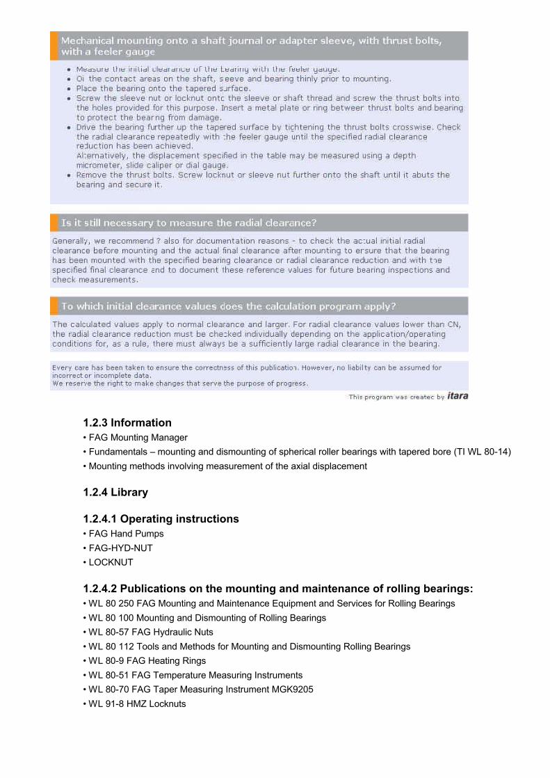
1.2.3 Information • FAG Mounting Manager • Fundamentals – mounting and dismounting of spherical roller bearings with tapered bore (TI WL 80-14) • Mounting methods involving measurement of the axial displacement
1.2.4 Library
1.2.4.1 Operating instructions • FAG Hand Pumps • FAG-HYD-NUT • LOCKNUT
1.2.4.2 Publications on the mounting and maintenance of rolling bearings: • WL 80 250 FAG Mounting and Maintenance Equipment and Services for Rolling Bearings • WL 80 100 Mounting and Dismounting of Rolling Bearings • WL 80-57 FAG Hydraulic Nuts • WL 80 112 Tools and Methods for Mounting and Dismounting Rolling Bearings • WL 80-9 FAG Heating Rings • WL 80-51 FAG Temperature Measuring Instruments • WL 80-70 FAG Taper Measuring Instrument MGK9205 • WL 91-8 HMZ Locknuts

2 Fundamentals
Mounting and dismounting bearings with a tapered bore (see also WL 80100/3 and WL 80102/5)
2.1 Mounting
Bearings with a tapered bore are fitted either directly onto a tapered shaft or with an adapter sleeve or withdrawal sleeve onto a cylindrical shaft. The thoroughly cleaned bearing bore and the seating surfaces on the shaft and on the sleeve may be oiled just very thinly prior to mounting. Although a thicker lubricant film would reduce friction and facilitate mounting, the lubricant would be gradually squeezed out of the fitting joints during operation. As a result, the tight fit would slacken, the ring or sleeve would start to creep along the shaft, and the surfaces would seize. As the bearing is pushed up the tapered surface, its inner ring is expanded, reducing the radial clearance. This makes the radial clearance reduction a yardstick for the tightness of the inner ring fit. The radial clearance reduction is the difference between the clearance values before and after mounting. So the radial clearance must be measured before mounting; it must then be continuously monitored as the bearing is pushed onto its tapered seat until the required clearance reduction, and thus the necessary tight fit, is obtained. Small and medium-sized bearings can be pushed onto their tapered seat with the help of a locknut. The nut is tighened by means of a hook wrench. Small bearings with an adapter sleeve are pushed onto the tapered seat of the sleeve by means of the adapter sleeve nut and a hook wrench. Small withdrawal sleeves are pressed into the gap between shaft and inner ring by means of the locknut. Larger bearings can be mounted using the FAG hydraulic method. With the hydraulic method, oil is pressed between the mating surfaces, e.g. machine oil or some oil with rust-dissolving additives. The oil film largely overcomes the friction between the mating parts so that they can be displaced easily in relation to one another without risking surface damage. For oil injection, oil grooves, feed ducts and threaded connections for the pumps must be provided in the shaft or sleeve. Very little oil is required for hydraulically mounting bearings with a tapered bore that sit directly on a tapered journal.
A medium-viscosity machine oil is used as pressure fluid. We recommend to use as thin an oil as possible with a viscosity of ≈ 75 mm
2/s at 20 °C (nominal viscosity 32 mm
2/s at 40 °C) for the mounting procedure to make sure
that the oil drains completely from the fitting joint after mounting.
During the mounting procedure, oil is pumped between the mating surfaces. The axial mounting forces are applied by tightening six or eight bolts in the locknut or adapter sleeve nut. A mounting washer prevents damage to the withdrawal sleeve and to the bearing ring. When the withdrawal sleeve is pressed between bearing and shaft, the oil feed line goes through the locknut. The displacement of the bearing or withdrawal sleeve is determined on the basis of the required radial clearance reduction.Before the radial clearance can be measured, the bearing must be relieved from the oil pressure. It takes 10 to 30 minutes until the high pressure oil has drained completely from the fitting joint. During this period, the axial preload must be maintained. Then the mounting device (nut with thrust bolts or hydraulic nut) is removed, and the locknut or sleeve nut is screwed further onto the shaft and secured.
The pictures show how a spherical roller bearing is mounted: · - onto a tapered journal, · - onto an adapter sleeve, · - onto a withdrawal sleeve

2.2 Dismounting
To dismount bearings that sit directly on a tapered shaft seat or on an adapter sleeve, the locking device of the locknut or sleeve nut must be loosened first. Then the nut must be turned back by the amount corresponding to the displacement. Next, the inner ring must be driven off the adapter sleeve or from its tapered shaft seat by means of light hammer taps. A metal drift or, even better, a mounting sleeve can be used. If a hydraulic nut can be used, the adapter sleeve/the loosened adapter sleeve nut is supported and the bearing is driven off the adapter sleeve. An adapter sleeve can be loosened with a hydraulic nut if the bearing is supported by a supporting ring. Of course the hydraulic nut must be supported by a washer or some similar device. Bearings mounted onto a withdrawal sleeve are dismounted with the help of an extraction nut. To this end, the axial fastening elements must be unscrewed. In difficult cases – especially with large bearings – thrust bolts can be used in addition to extraction nuts. In these cases, a washer is inserted between inner ring and thrust bolts. Withdrawal sleeves can be dismounted more easily and economically by means of a hydraulic nut. Withdrawal sleeves that project over the shaft end must be supported by a thick-walled ring. Caution: Press-fitted assemblies are released abruptly! Because of the risk of accident, the axial movement of the bearing or withdrawal sleeve must be restricted by means of a locknut, an adapter sleeve nut or a stop element.
3 Mounting methods involving measurement of the axial displacement
The tapered bore bearing is placed onto its tapered seat. The bearing is positioned at the starting point in positive contact by means of a hydraulic nut exerting an individually specified pressure. The pressure can be measured accurately by means of a digital pressure gauge, permitting simple and reliable determination of the starting position. Then the defined axial displacement “s” is measured accurately with a depth micrometer,slide caliper or dial gauge and the bearing is pushed up the shaft to its correct end position and secured.
3.1 Radial clearance reduction
As the bearing is driven up the tapered seat, its inner ring is expanded, reducing the radial clearance. This makes the radial clearance reduction Δr a yardstick for the tightness of the inner ring fit. The radial clearance reduction is the difference between the radial clearance before and after bearing mounting. In the default settings for the inner ring expansion ε
d, the values preset for the calculation of the bearing types listed ensure a sufficiently tight fit.

3.2 Special cases
In some cases, bearings must be mounted with a larger radial clearance reduction. This is often the case: · - with high shock-type loads · - with thin-walled hollow shafts · - with bearings where the shaft is considerably cooler than the inner ring · - when special requirements on the operating clearance have to be met
In order to avoid unpermissible tangential stresses, a value of 0.0007 x d should not be exceeded. In case of higher values please consult the FAG field staff. With displacements in the upper range, the minimum radial clearance after mounting must be observed; if necessary, a larger initial radial clearance (C3, C4, C5) should be selected.
3.3 Starting position
1. Depending on the mounting situation, the bearing is placed either directly onto the tapered shaft or onto a cylindrical shaft with an adapter sleeve or withdrawal sleeve and moved to its starting position.
2. The hydraulic nut is screwed onto the shaft end or onto the adapter sleeve or withdrawal sleeve and connected to the hand pump (use a hand pump set PUMP1000…DIGI with a digital pressure gauge).
3. The bearing is pushed into its starting position in positive contact exerting a defined pressure. The required oil pressure is determined by the bearing size and the number of sliding surfaces. In the starting position, any form inaccuracies are compensated, and the ring is already slightly expanded.
3.4 Axial displacement from the starting position
When the bearing has been pushed into its starting position, the dial indicator of the displacement gauge must be zeroized. The bearing is driven up the tapered shaft by pumping until the dial indicator shows that the specified displacement “s” has been obtained. If the FAG hydraulic method is used, oil is continously pressed into the fitting joint by means of a second pump during the process. After the bearing has been driven up to its end position using the FAG hydraulic method, the next steps are as follows:
1. The pressure inside the hydraulic nut must be maintained (10 to 30 minutes), and the return valve at the second pump must be opened to allow the high pressure oil to drain from the fitting joint.
2. The return valve at the pump for the high pressure hose leading to the hydraulic nut must be opened to allow the high pressure oil to drain from the hydraulic nut.
3. To let the oil drain completely, the annular piston of the hydraulic nut must be pushed back to its initial position. This is most easily done by screwing the hydraulic nut further onto the shaft or sleeve thread.
4. The bearing must be secured with a locknut and accessories. The tightness of the bearing fit is reduced by temperature differences. The bearing and the shaft must have the same temperature during the mounting procedure. If necessary, the bearing must be heated, or the shaft must be cooled.
3.5 Reduction of the fit tightness by smoothening
As the bearing is pushed onto its seat, the surfaces are smoothened, reducing the tightness of the desired bearing fit. The values listed in the tables take into account the following factors:
• the smoothening of one sliding surface • utilisation of new FAG components • the surface roughness of the shaft R
a= 1.6 µm

For surfaces already smoothened by repeated mountings, the deviation of the radial clearance reduction or displacement can be calculated using the FAG Mounting Manager program. The reduction of the fit tightness due to smoothening must be checked with small bearings; with larger bearings the effect is negligible.
3.6 Procedure 1. Check if the shaft seats are within tolerance, if bearings and all the required accessories (locknut, sleeve, locking element) and tools (pump, hydraulic nut) of the right design are available. Attention: Generally, the FAG hydraulic nut allocated to a bearing in the program must be used; if, for example, the piston surface deviates from the value in the program, the starting pressure values determined by means of the program must not be used. The necessary approximate values must be determined using the FAG Mounting Manager. 2. Check the mounting conditions:
Mounting with one sliding surface
• Bearings fitted directly onto a tapered shaft journal • Bearings fitted onto a free adapter sleeve
Mounting with two sliding surfaces • Supported bearings fitted onto an adapter sleeve • Bearings fitted onto a withdrawal sleeve
3. Oil all sliding surfaces thinly with machine oil. 4. Place the bearing onto the tapered seat and screw the hydraulic nut onto the shaft or sleeve thread until it abuts the bearing’s inner ring. 5. Screw the displacement gauge in the hydraulic nut. 6. Move the bearing to its “starting position" by pumping oil into the hydraulic nut until the starting pressure determined by means of the calculation program has been built up. 7. Zeroize the dial indicator. Drive the bearing up the tapered shaft by pumping more oil into the hydraulic nut until the dial indicator shows that the specified displacement “s” has been obtained. If you use the FAG hydraulic method, keep pumping oil into the fitting joint by means of a second pump. 8. After mounting, open the return valve at the hand pump to allow the high pressure oil to drain from the fitting joint.
9. It takes 10 to 30 minutes until the high pressure oil has drained completely from the fitting joint. During this period, the axial preload must be maintained. Then the mounting device (nut with thrust bolts or hydraulic nut) is removed, and the locknut or sleeve nut is screwed further onto the shaft and secured.