Embed Size (px)
Citation preview
Ceramic insert with chipbreaker
Wiper insert for finishing
Multi-edge cutter for cast iron MFK
MFK
Double-sided insert with free cutting geometry to resist chatter
10 usable cutting edges per insert.
Tough edge with low cutting forces.
New CVD grade CA420M for longer tool life.
NEW
1
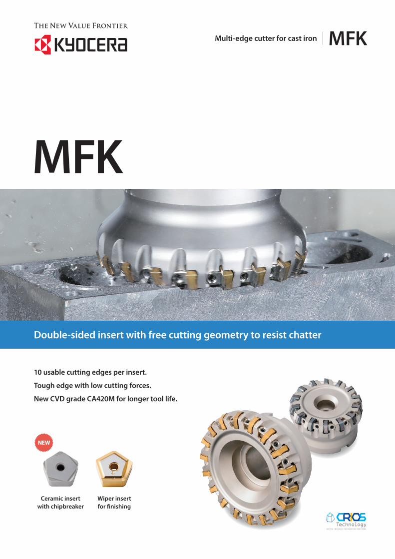
MFK Competitor A
3,000
2,500
2,000
1,500
1,000
500
0
Cutt
ing
forc
e (N)
Cutt
ing
forc
e (N)
MFK Competitor B
1,000
800
600
400
200
0
7 % 16 %
Resultant force in radial direction Resultant force in axial direction
MFK Competitor A
3,000
2,500
2,000
1,500
1,000
500
0
Cutt
ing
forc
e (N)
Cutt
ing
forc
e (N)
MFK Competitor B
1,000
800
600
400
200
0
7 % 16 %
Resultant force in radial direction Resultant force in axial direction
1 Low cutting forces prevent chattering
2 Tough and reliable insert construction prevents fracturing
Low cutting forces with helical cutting edge design.
Tough and reliable dual angle edge design.
Second main cutting edge
First main cutting edge
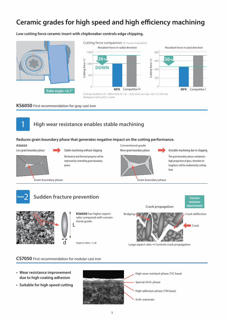
Cutting force comparison (In-house evaluation)
Cutting conditions: Vc = 180 m/min, fz = 0.3 mm/t, ap × ae = 3.0 × 62 mm, dry Workpiece: GGG60, ø125
Fracture resistance comparison (In-house evaluation)
Cutting conditions: Vc = 300 m/min, fz = 0.5 mm/t, ap = 2.0 mm, wet Workpiece: Nodular cast iron (4 bores)
Surface finish comparison (In-house evaluation)
MFK
Cutting conditions: Vc = 180 m/min, fz = 0.3 mm/t, ap × ae = 3 × 78 mm, dry Workpiece:GGG60
Competitor E
Chattering creates poor surface
0 5 10Cutting time (min)
CA420M
PR1510
Competitor D (CVD)
Competitor C (CVD)
MFK
15 20 25
25 %
A.R. Max. +15°
Burr comparison
MFK
Competitor F
Cutting direction
Burr
Sharp cutting prevents burr formation
• Tough edge with low cutting forces enable stable machining.• Uses 10-edge inserts for economical machining.
Cutter for cast iron
MFK
2
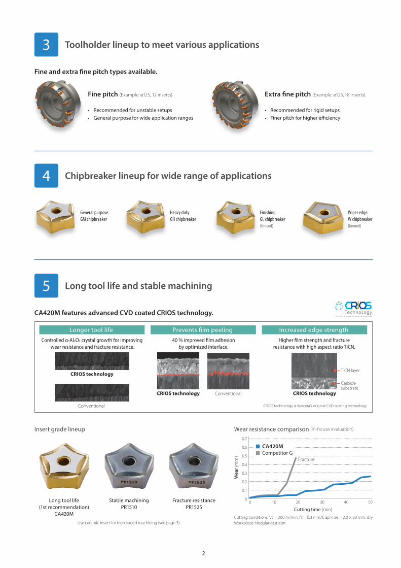
Longer tool life Increased edge strength
CRIOS technology is Kyocera’s original CVD coating technology.
Controlled α-Al2O3 crystal growth for improving wear resistance and fracture resistance.
40 % improved �lm adhesionby optimized interface.
Prevents �lm peeling
Higher �lm strength and fractureresistance with high aspect ratio TiCN.
Conventional
Conventional
TiCN layer
Carbide substrate
CRIOS technology
CRIOS technology CRIOS technology
4 Chipbreaker lineup for wide range of applications
General purpose: GM chipbreaker
5 Long tool life and stable machining
CA420M features advanced CVD coated CRIOS technology.
Insert grade lineup
Long tool life(1st recommendation)
CA420M
Stable machining PR1510
Fracture resistance PR1525
3 Toolholder lineup to meet various applications
Fine pitch (Example: ø125, 12 inserts)
• Recommended for unstable setups• General purpose for wide application ranges
Extra fine pitch (Example: ø125, 18 inserts)
• Recommended for rigid setups• Finer pitch for higher efficiency
Fine and extra fine pitch types available.
Cutting conditions: Vc = 200 m/min, fz = 0.3 mm/t, ap × ae = 2.0 × 80 mm, dryWorkpiece: Nodular cast iron
0 10 20 30 40 50
0.7
0.6
0.5
0.4
0.3
0.2
0.1
0
Wea
r (mm)
Cutting time (min)
Fracture
CA420MCompetitor G
Wear resistance comparison (In-house evaluation)
Use ceramic insert for high speed machining (see page 3).
Heavy duty: GH chipbreaker
Finishing: GL chipbreaker (Ground)
Wiper edge: W chipbreaker (Ground)
3
Bridging
Aspect ratio = L/d
Crack deflection
CrackL
d
Grain boundary phase Grain boundary phase
Special Al2O3 phase
High adhesion phase (TiN base)
Si3N4 substrate
High wear resistant phase (TiC base)
MFK Competitor H
Cutt
ing
forc
e (N)
Resultant force in radial direction
1,500
1,000
500
0
26 %
DOWN
Cutt
ing
forc
e (N)
MFK Competitor I
Resultant force in axial direction
800
600
400
200
0
36 %
Large aspect ratio Controls crack propagation
The grain boundary phase contained a high proportion of glass, therefore its toughness will be weakened by cutting heat.
Mechanical and thermal property will be improved by controlling grain boundary phase.
Conventional gradeKS6050
KS6050 has higher aspect ratio compared with conven-tional grade.
Crack propagation
Less grain boundary phase More grain boundary phase Unstable machining due to chippingStable machining without chipping
• Wear resistance improvement due to high coating adhesion
• Suitable for high speed cutting
Cutting conditions: Vc = 600 m/min, fz = 0.1 – 0.25 mm/t, ae × ap = 62.5 × 2 mm, dry Workpiece: GG25, ø125, 1 insert
Cutting force comparison (In-house evaluation)
1 High wear resistance enables stable machining
Point2 Sudden fracture prevention
Ceramic grades for high speed and high efficiency machiningLow cutting force ceramic insert with chipbreaker controls edge chipping.
Reduces grain boundary phase that generates negative impact on the cutting performance.
Fracture resistance
improvement
KS6050 First recommendation for gray cast iron
CS7050 First recommendation for nodular cast iron
Rake angle +6.7°
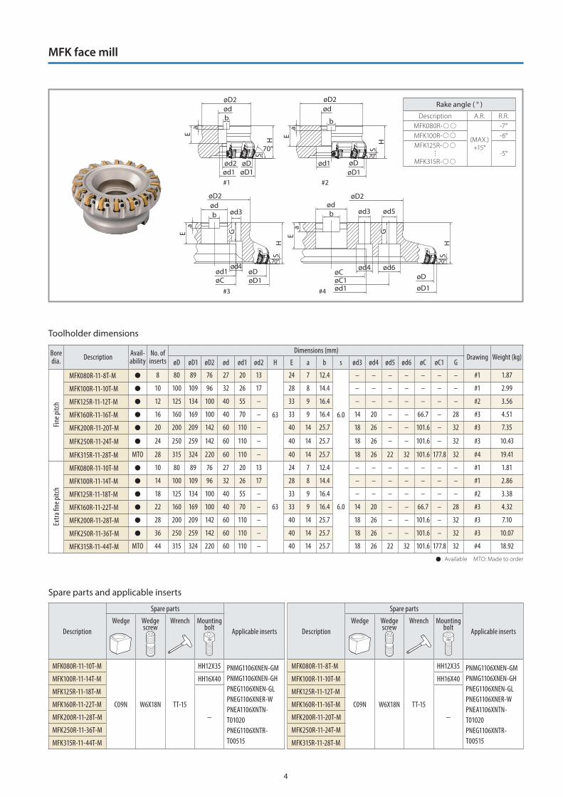
4
#1 #2
#3 #4
S
GG
b
aE
H
S
b
aE
H
b
aE
SH
S
GG
b
aE
H
70°70°
70°70°
øC øD1øD
ød4
ød3ød
øD1øDød1
ød
øD1øDød2
ød1
ødøD2 øD2
øD1
øDøC1øC
ød6
ød5
ød4
ød3ød
ød1
ød1
øD2 øD2
Toolholder dimensions
Bore dia. Description Avail
abilityNo. of inserts
Dimensions (mm)Drawing Weight (kg)
øD øD1 øD2 ød ød1 ød2 H E a b s ød3 ød4 ød5 ød6 øC øC1 G
Fine p
itch
MFK080R118TM 8 80 89 76 27 20 13
63
24 7 12.4
6.0
– – – – – – – #1 1.87
MFK100R1110TM 10 100 109 96 32 26 17 28 8 14.4 – – – – – – – #1 2.99
MFK125R1112TM 12 125 134 100 40 55 – 33 9 16.4 – – – – – – – #2 3.56
MFK160R1116TM 16 160 169 100 40 70 – 33 9 16.4 14 20 – – 66.7 – 28 #3 4.51
MFK200R1120TM 20 200 209 142 60 110 – 40 14 25.7 18 26 – – 101.6 – 32 #3 7.35
MFK250R1124TM 24 250 259 142 60 110 – 40 14 25.7 18 26 – – 101.6 – 32 #3 10.43
MFK315R1128TM MTO 28 315 324 220 60 110 – 40 14 25.7 18 26 22 32 101.6 177.8 32 #4 19.41
Extra
fine p
itch
MFK080R1110TM 10 80 89 76 27 20 13
63
24 7 12.4
6.0
– – – – – – – #1 1.81
MFK100R1114TM 14 100 109 96 32 26 17 28 8 14.4 – – – – – – – #1 2.86
MFK125R1118TM 18 125 134 100 40 55 – 33 9 16.4 – – – – – – – #2 3.38
MFK160R1122TM 22 160 169 100 40 70 – 33 9 16.4 14 20 – – 66.7 – 28 #3 4.32
MFK200R1128TM 28 200 209 142 60 110 – 40 14 25.7 18 26 – – 101.6 – 32 #3 7.10
MFK250R1136TM 36 250 259 142 60 110 – 40 14 25.7 18 26 – – 101.6 – 32 #3 10.07
MFK315R1144TM MTO 44 315 324 220 60 110 – 40 14 25.7 18 26 22 32 101.6 177.8 32 #4 18.92
: Available MTO: Made to order
Rake angle ( ° )
Description A.R. R.R.MFK080R-
(MAX.)+15°
-7°MFK100R- -6°MFK125R-
MFK315R--5°
MFK face mill
Spare parts and applicable inserts
Description
Spare parts
Applicable inserts Description
Spare parts
Applicable insertsWedge Wedge
screwWrench Mounting
boltWedge Wedge
screwWrench Mounting
bolt
MFK080R1110TM
C09N W6X18N TT15
HH12X35 PNMG1106XNENGMPNMG1106XNENGHPNEG1106XNENGLPNEG1106XNERWPNEA1106XNTNT01020PNEG1106XNTRT00515
MFK080R118TM
C09N W6X18N TT15
HH12X35 PNMG1106XNENGMPNMG1106XNENGHPNEG1106XNENGLPNEG1106XNERWPNEA1106XNTNT01020PNEG1106XNTRT00515
MFK100R1114TM HH16X40 MFK100R1110TM HH16X40
MFK125R1118TM
−
MFK125R1112TM
−
MFK160R1122TM MFK160R1116TM
MFK200R1128TM MFK200R1120TM
MFK250R1136TM MFK250R1124TM
MFK315R1144TM MFK315R1128TM
5
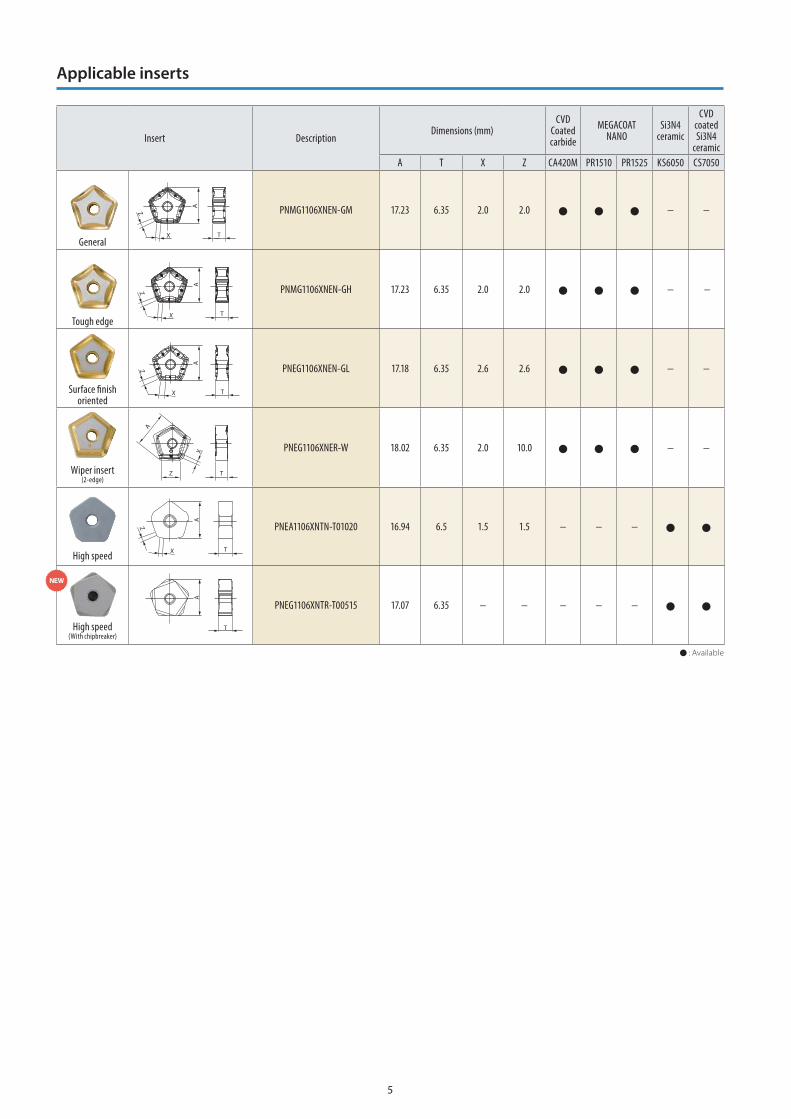
Insert DescriptionDimensions (mm)
CVD Coated carbide
MEGACOATNANO
Si3N4 ceramic
CVD coated Si3N4
ceramicA T X Z CA420M PR1510 PR1525 KS6050 CS7050
General
PNMG1106XNENGM 17.23 6.35 2.0 2.0 − −
Tough edge
PNMG1106XNENGH 17.23 6.35 2.0 2.0 − −
Surface finish oriented
PNEG1106XNENGL 17.18 6.35 2.6 2.6 − −
Wiper insert (2edge)
PNEG1106XNERW 18.02 6.35 2.0 10.0 − −
High speed
PNEA1106XNTNT01020 16.94 6.5 1.5 1.5 − − −
High speed(With chipbreaker)
PNEG1106XNTRT00515 17.07 6.35 − − − − −
: Available
A
X
Z
T
A
X
Z
T
T
A
X
Z
X
Z
A
T
A
X
Z
T
T
A
Applicable inserts
NEW
6
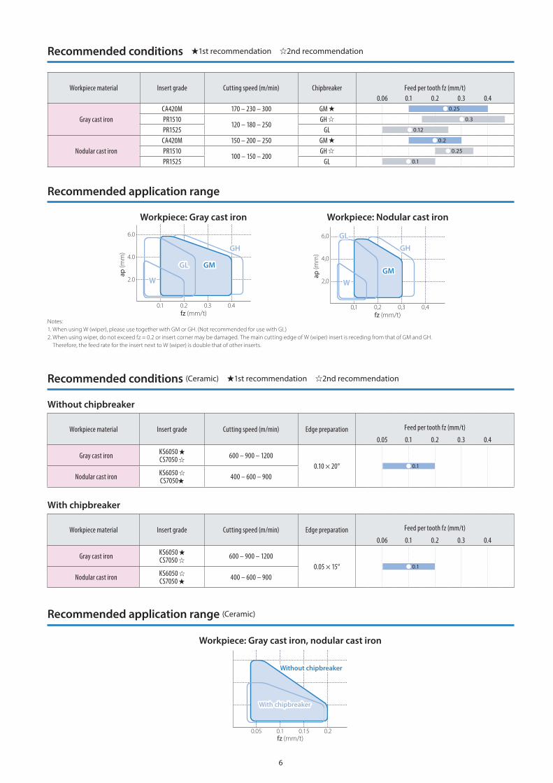
fz (mm/t)
ap (m
m)
6.0
4.0
2.0
0.05 0.1 0.15 0.2
With chipbreaker
Without chipbreaker
Notes: 1. When using W (wiper), please use together with GM or GH. (Not recommended for use with GL)2. When using wiper, do not exceed fz = 0.2 or insert corner may be damaged. The main cutting edge of W (wiper) insert is receding from that of GM and GH.
Therefore, the feed rate for the insert next to W (wiper) is double that of other inserts.
Workpiece: Gray cast iron Workpiece: Nodular cast iron
GL GM
W
GH
fz (mm/t)
ap (m
m)
6.0
4.0
2.0
0.1 0.2 0.3 0.4
fz (mm/t)ap
(mm)
GL
GMW
GH
6,0
4,0
2,0
0,1 0,2 0,3 0,4
Workpiece material Insert grade Cutting speed (m/min) Chipbreaker Feed per tooth fz (mm/t)0.06 0.1 0.2 0.3 0.4
Gray cast ironCA420M 170 – 230 – 300 GM PR1510
120 – 180 – 250GH
PR1525 GL
Nodular cast ironCA420M 150 – 200 – 250 GM PR1510
100 – 150 – 200GH
PR1525 GL
0.25
0.3
0.12
0.2
0.25
0.1
Workpiece material Insert grade Cutting speed (m/min) Edge preparation Feed per tooth fz (mm/t)
0.05 0.1 0.2 0.3 0.4
Gray cast iron KS6050 CS7050 600 – 900 – 1200
0.10 × 20°Nodular cast iron KS6050
CS7050 400 – 600 – 900 0.1
Without chipbreaker
Workpiece material Insert grade Cutting speed (m/min) Edge preparation Feed per tooth fz (mm/t)
0.06 0.1 0.2 0.3 0.4
Gray cast iron KS6050 CS7050 600 – 900 – 1200
0.05 × 15°Nodular cast iron KS6050
CS7050 400 – 600 – 900 0.1
With chipbreaker
Recommended conditions 1st recommendation 2nd recommendation
Recommended application range
Recommended conditions (Ceramic) 1st recommendation 2nd recommendation
Recommended application range (Ceramic)
Workpiece: Gray cast iron, nodular cast iron
TZE00080©2015 KYOCERA Corporation | www.kyocera-unimerco.com/contact-us
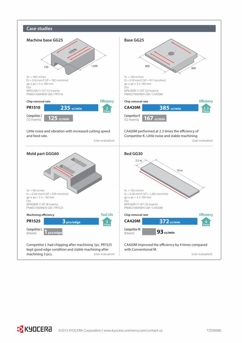
PR1510
Competitor J(12 Inserts)
CA420M
Competitor K(12 Inserts)
Case studies
Chip removal rate
235 cc/min
125 cc/min
Chip removal rate
385 cc/min
167 cc/min
720 1,000 800800
2.2 m
10 m
Vc = 160 m/minfz = 0.16 mm/t (Vf = 782 mm/min)ap × ae = 3 × 100 mmDryMFK125R-11-12T (12 Inserts)PNMG1106XNEN-GM / PR1510
Mold part GGG60
PR1525
Competitor L(8 Inserts)
Vc = 90 m/minfz = 0.34 mm/t (Vf = 974 mm/min)ap × ae = 2 × – 60 mmDryMFK080R-11-8T (8 Inserts)PNMG1106XNEN-GM / PR1525
CA420M
Competitor M(8 Inserts)
Bed GG30
Base GG25Machine base GG25
Vc = 150 m/minfz = 0.26 mm/t (Vf = 1,242 mm/min)ap × ae = 3 × 100 mmDryMFK160R-11-16T (16 Inserts)PNMG1106XNEN-GM / CA420M
Vc = 160 m/minfz = 0.18 mm/t (Vf = 917 mm/min)ap × ae = 3 × 140 mmDryMFK200R-11-20T (20 Inserts)PNMG1106XNEN-GM / CA420M
Little noise and vibration with increased cutting speed and feed rate. (User evaluation)
Competitor L had chipping after machining 1pc. PR1525 kept good edge condition and stable machining after machining 3 pcs. (User evaluation)
CA420M improved the efficiency by 4 times compared with Conventional M. (User evaluation)
CA420M performed at 2.3 times the efficiency of Competitor K. Little noise and stable machining. (User evaluation)
Chip removal rateMachining efficiency
Efficiency
2 Times
372 cc/min
93 cc/min
3 pcs/edge
1 pcs/edge
Efficiency
2.3 Times
Tool Life
3 Times
Efficiency
4 Times