Embed Size (px)
Citation preview

April 2010 © 2010 Fluke Corporation. All rights reserved. Specifications are subject to change without notice. All product names are trademarks of their respective companies. 1
27 II/28 II
Digital Multimeters
Calibration Information
Introduction XWWarning
To avoid electric shock or injury, do not perform the performance tests or calibration adjustment procedures unless qualified to do so.
The information provided in this document is for the use of qualified personnel only.
The 27 II/28 II Calibration Information provides adjustment and performance test procedures for the Fluke Model 27 II and 28 II Digital Multimeters (hereafter known as the Meter).
This document includes the following information:
• Safety Information and International Electrical Symbols (page 2) • Specifications (page 5) • Testing the Fuse (page 9) • Cleaning (page 9) • Performance Tests (page 11) • Calibration Adjustment (page 19) • Replacement Parts (page 24) • Complete Warranty (page 27)
See the 27 II/28 II Users Manual for complete operating instructions.
Contact Information To contact Fluke, call one of the following telephone numbers:
USA: 1-888-99-FLUKE (1-888-993-5853) Canada: 1-800-36-FLUKE (1-800-363-5853) Europe: +31 402-675-200 Japan: +81-3-3434-0181 Singapore: +65-738-5655 Anywhere in the world: +1-425-446-5500
Or, visit Fluke's Web site at www.fluke.com. To register your product, visit register.fluke.com
27 II/28 II Calibration Information
2
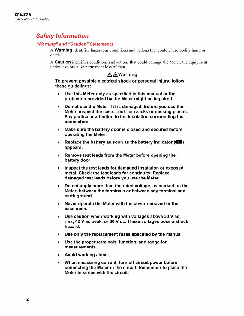
Safety Information "Warning" and "Caution" Statements
A Warning identifies hazardous conditions and actions that could cause bodily harm or death.
A Caution identifies conditions and actions that could damage the Meter, the equipment under test, or cause permanent loss of data.
XWWarning To prevent possible electrical shock or personal injury, follow these guidelines:
• Use this Meter only as specified in this manual or the protection provided by the Meter might be impaired.
• Do not use the Meter if it is damaged. Before you use the Meter, inspect the case. Look for cracks or missing plastic. Pay particular attention to the insulation surrounding the connectors.
• Make sure the battery door is closed and secured before operating the Meter.
• Replace the battery as soon as the battery indicator () appears.
• Remove test leads from the Meter before opening the battery door.
• Inspect the test leads for damaged insulation or exposed metal. Check the test leads for continuity. Replace damaged test leads before you use the Meter.
• Do not apply more than the rated voltage, as marked on the Meter, between the terminals or between any terminal and earth ground.
• Never operate the Meter with the cover removed or the case open.
• Use caution when working with voltages above 30 V ac rms, 42 V ac peak, or 60 V dc. These voltages pose a shock hazard.
• Use only the replacement fuses specified by the manual.
• Use the proper terminals, function, and range for measurements.
• Avoid working alone.
• When measuring current, turn off circuit power before connecting the Meter in the circuit. Remember to place the Meter in series with the circuit.

Digital Multimeters Safety Information
3
• When making electrical connections, connect the common test lead before connecting the live test lead; when disconnecting, disconnect the live test lead before disconnecting the common test lead.
• Do not use the Meter if it operates abnormally. Protection may be impaired. When in doubt, have the Meter serviced.
• Do not use the Meter around explosive gas, vapor or in damp or wet environments.
• Use only three 1.5-V AA batteries, properly installed in the Meter case, to power the Meter.
• When servicing the Meter, use only specified replacement parts.
• When using probes, keep fingers behind the finger guards on the probes.
• Do not use the Low-Pass Filter to verify the presence of hazardous voltages. Voltages greater than what is indicated may be present. First, make a voltage measurement without the filter to detect the possible presence of hazardous voltage. Then add the filter.
WCaution To avoid possible damage to the Meter or to the equipment under test, follow these guidelines:
• Disconnect circuit power and discharge all high-voltage capacitors before testing resistance, continuity, diodes, or capacitance.
• Use the proper terminals, function, and range for all measurements.
• Before measuring current, check the Meter’s fuses. (See “Fuse Test”.)

27 II/28 II Calibration Information
4
Electrical Symbols Table 1 lists the electrical symbols that appear in this document and on the Meter
Table 1. Symbols
B AC (Alternating Current) J Earth ground
F DC (Direct Current) I Fuse
X Hazardous voltage P Conforms to European Union directives.
W Risk of Danger. Important information. See Manual.
) Conforms to relevant Canadian Standards Association directives.
Battery. Low battery when displayed.
T Double insulated
R Continuity test or continuity beeper tone.
E Capacitance
CAT III
IEC Overvoltage Category III
CAT III equipment is designed to protect against transients in equipment in fixed-equipment installations, such as distribution panels, feeders and short branch circuits, and lighting systems in large buildings.
CAT IV
IEC Overvoltage Category IV CAT IV equipment is designed to protect against transients from the primary supply level, such as an electricity meter or an overhead or underground utility service.
~ Do not dispose of this product as unsorted municipal waste. Go to Fluke’s website for recycling information.
Diode
® Inspected and licensed by TÜV Product Services. ; Conforms to relevant Australian standards.
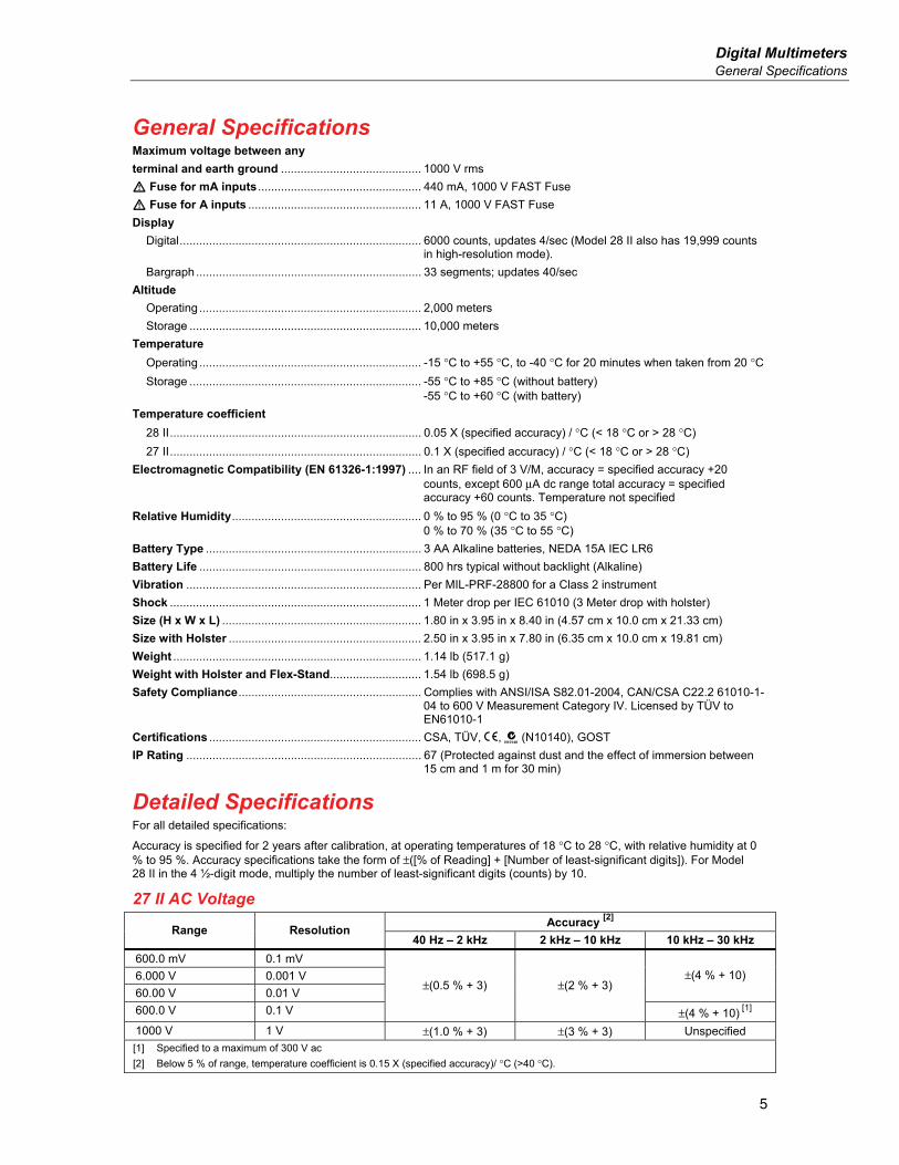
Digital Multimeters General Specifications
5
General Specifications Maximum voltage between any
terminal and earth ground ........................................... 1000 V rms
W Fuse for mA inputs .................................................. 440 mA, 1000 V FAST Fuse
W Fuse for A inputs ..................................................... 11 A, 1000 V FAST Fuse
Display
Digital.......................................................................... 6000 counts, updates 4/sec (Model 28 II also has 19,999 counts in high-resolution mode).
Bargraph ..................................................................... 33 segments; updates 40/sec
Altitude
Operating .................................................................... 2,000 meters
Storage ....................................................................... 10,000 meters
Temperature
Operating .................................................................... -15 °C to +55 °C, to -40 °C for 20 minutes when taken from 20 °C
Storage ....................................................................... -55 °C to +85 °C (without battery) -55 °C to +60 °C (with battery)
Temperature coefficient
28 II............................................................................. 0.05 X (specified accuracy) / °C (< 18 °C or > 28 °C)
27 II............................................................................. 0.1 X (specified accuracy) / °C (< 18 °C or > 28 °C)
Electromagnetic Compatibility (EN 61326-1:1997) .... In an RF field of 3 V/M, accuracy = specified accuracy +20 counts, except 600 μA dc range total accuracy = specified accuracy +60 counts. Temperature not specified
Relative Humidity.......................................................... 0 % to 95 % (0 °C to 35 °C) 0 % to 70 % (35 °C to 55 °C)
Battery Type .................................................................. 3 AA Alkaline batteries, NEDA 15A IEC LR6
Battery Life .................................................................... 800 hrs typical without backlight (Alkaline)
Vibration ........................................................................ Per MIL-PRF-28800 for a Class 2 instrument
Shock ............................................................................. 1 Meter drop per IEC 61010 (3 Meter drop with holster)
Size (H x W x L) ............................................................. 1.80 in x 3.95 in x 8.40 in (4.57 cm x 10.0 cm x 21.33 cm)
Size with Holster ........................................................... 2.50 in x 3.95 in x 7.80 in (6.35 cm x 10.0 cm x 19.81 cm)
Weight ............................................................................ 1.14 lb (517.1 g)
Weight with Holster and Flex-Stand............................ 1.54 lb (698.5 g)
Safety Compliance........................................................ Complies with ANSI/ISA S82.01-2004, CAN/CSA C22.2 61010-1-04 to 600 V Measurement Category IV. Licensed by TÜV to EN61010-1
Certifications ................................................................. CSA, TÜV, P, ; (N10140), GOST
IP Rating ........................................................................ 67 (Protected against dust and the effect of immersion between 15 cm and 1 m for 30 min)
Detailed Specifications For all detailed specifications:
Accuracy is specified for 2 years after calibration, at operating temperatures of 18 °C to 28 °C, with relative humidity at 0 % to 95 %. Accuracy specifications take the form of ±([% of Reading] + [Number of least-significant digits]). For Model 28 II in the 4 ½-digit mode, multiply the number of least-significant digits (counts) by 10.
27 II AC Voltage Accuracy
[2]
Range Resolution 40 Hz – 2 kHz 2 kHz – 10 kHz 10 kHz – 30 kHz
600.0 mV 0.1 mV
6.000 V 0.001 V
60.00 V 0.01 V
±(4 % + 10)
600.0 V 0.1 V
±(0.5 % + 3) ±(2 % + 3)
±(4 % + 10) [1]
1000 V 1 V ±(1.0 % + 3) ±(3 % + 3) Unspecified
[1] Specified to a maximum of 300 V ac
[2] Below 5 % of range, temperature coefficient is 0.15 X (specified accuracy)/ °C (>40 °C).
27 II/28 II Calibration Information
6
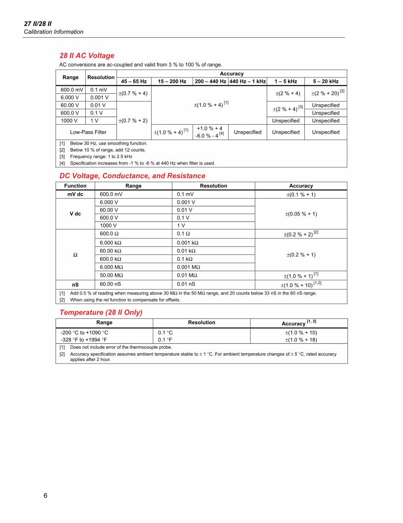
28 II AC Voltage AC conversions are ac-coupled and valid from 3 % to 100 % of range.
Accuracy Range Resolution
45 – 65 Hz 15 – 200 Hz 200 – 440 Hz 440 Hz – 1 kHz 1 – 5 kHz 5 – 20 kHz
600.0 mV 0.1 mV
6.000 V 0.001 V ±(0.7 % + 4) ±(2 % + 4) ±(2 % + 20)
[2]
60.00 V 0.01 V Unspecified
600.0 V 0.1 V ±(2 % + 4)
[3]
Unspecified
1000 V 1 V
±(1.0 % + 4) [1]
Unspecified Unspecified
Low-Pass Filter
±(0.7 % + 2)
±(1.0 % + 4) [1]
+1.0 % + 4
-6.0 % - 4 [4]
Unspecified Unspecified Unspecified
[1] Below 30 Hz, use smoothing function.
[2] Below 10 % of range, add 12 counts.
[3] Frequency range: 1 to 2.5 kHz
[4] Specification increases from -1 % to -6 % at 440 Hz when filter is used.
DC Voltage, Conductance, and Resistance Function Range Resolution Accuracy
mV dc 600.0 mV 0.1 mV ±(0.1 % + 1)
6.000 V 0.001 V
60.00 V 0.01 V
600.0 V 0.1 V V dc
1000 V 1 V
±(0.05 % + 1)
600.0 Ω 0.1 Ω ±(0.2 % + 2) [2]
6.000 kΩ 0.001 kΩ
60.00 kΩ 0.01 kΩ
600.0 kΩ 0.1 kΩ
6.000 MΩ 0.001 MΩ
±(0.2 % + 1) Ω
50.00 MΩ 0.01 MΩ ±(1.0 % + 1) [1]
nS 60.00 nS 0.01 nS ±(1.0 % + 10) [1,2]
[1] Add 0.5 % of reading when measuring above 30 MΩ in the 50 MΩ range, and 20 counts below 33 nS in the 60 nS range.
[2] When using the rel function to compensate for offsets.
Temperature (28 II Only) Range Resolution Accuracy
[1, 2]
-200 °C to +1090 °C -328 °F to +1994 °F
0.1 °C 0.1 °F
±(1.0 % + 10) ±(1.0 % + 18)
[1] Does not include error of the thermocouple probe.
[2] Accuracy specification assumes ambient temperature stable to ± 1 °C. For ambient temperature changes of ± 5 °C, rated accuracy applies after 2 hour.

Digital Multimeters Detailed Specifications
7
AC Current Accuracy
Function Range Resolution Burden Voltage 27 II [1, 2]
(40 Hz – 1 kHz) 28 II
[3]
(45 Hz – 2 kHz)
600.0 μA 0.1 μA 100 μV/μA μA ac
6000 μA 1 μA 100 μV/μA
60.00 mA 0.01 mA 1.8 mV/mA mA ac
400.0 mA [4]
0.1 mA 1.8 mV/mA
6.000 A 0.001 A 0.03 V/A A ac
10.00 A [5,6]
0.01 A 0.03 V/A
±(1.5 % + 2) ±(1.0 % + 2)
[1] AC conversion for the 27 II is ac coupled and calibrated to the rms value of a sine wave input.
[2] Below 300 counts, add 1 count and the temperature coefficient is 0.15 x (specified accuracy) / °C (>40 °C).
[3] AC conversions for the 28 II are ac coupled, true rms responding, and valid from 3 % to 100 % of range, except 400 mA range. (5 % to 100 % of range) and 10 A range (15 % to 100 % or range).
[4] 400 mA continuous. 600 mA for 18 hr maximum.
[5] W 10 A continuous up to 35 °C. < 20 minutes on, 5 minutes off at 35 °C to 55 °C. >10 A to 20 A for 30 seconds maximum, 5 minutes off.
[6] >10 A accuracy unspecified.
DC Current Accuracy
Function Range Resolution Burden Voltage 27 II 28 II
600.0 μA 0.1 μA 100 μV/μA ±(0.2 % + 4) ±(0.2 % + 4) μA dc
6000 μA 1 μA 100 μV/μA ±(0.2 % + 2) ±(0.2 % + 2)
60.00 mA 0.01 mA 1.8 mV/mA ±(0.2 % + 4) ±(0.2 % + 4) mA dc
400.0 mA [1]
0.1 mA 1.8 mV/mA ±(0.2 % + 2) ±(0.2 % + 2)
6.000 A 0.001 A 0.03 V/A ±(0.2 % + 4) ±(0.2 % + 4) A dc
10.00 A [2,3]
0.01 A 0.03 V/A ±(0.2 % + 2) ±(0.2 % + 2)
[1] 400 mA continuous; 600 mA for 18 hr maximum.
[2] W 10 A continuous up to 35 °C. < 20 minutes on, 5 minutes off at 35 °C to 55 °C. >10 A to 20 A for 30 seconds maximum, 5 minutes off.
[3] >10 A accuracy unspecified.
Capacitance Range Resolution Accuracy
10.00 nF 0.01 nF
100.0 nF 0.1 nF ±(1.0 % + 2)
[1]
1.000 μF 0.001 μF
10.00 μF 0.01 μF
100.0 μF 0.1 μF
9999 μF 1 μF
±(1.0 % + 2)
[1] With a film capacitor or better, using the rel mode to zero residual.
Diode Range Resolution Accuracy
2.000 V 0.001 V ±(1.0 % + 1)
Frequency Range Resolution Accuracy
199.99 Hz 0.01 Hz
1999.9 Hz 0.1 Hz
19.999 kHz 0.001 kHz
199.99 kHz 0.01 kHz
±(0.005 % + 1) [1]
>200 kHz 0.1 kHz Unspecified
[1] From 0.5 Hz to 200 kHz and for pulse widths > 2 μs.

27 II/28 II Calibration Information
8
Frequency Counter Sensitivity and Trigger Levels Minimum Sensitivity (RMS Sine Wave)
Input Range 5 Hz – 20 kHz 0.5 Hz – 200 kHz
Approximate Trigger Level (DC Voltage Function)
600 mV dc 70 mV (to 400 Hz) 70 mV (to 400 Hz) 40 mV
600 mV ac 150 mV 150 mV -
6 V 0.3 V 0.7 V 1.7 V
60 V 3 V 7 V (≤140 kHz) 4 V
600 V 30 V 70 V (≤14.0 kHz) 40 V
1000 V 100 V 200 V (≤1.4 kHz) 100 V
Duty Cycle (Vdc and mVdc) Range Accuracy
0.0 % to 99.9 % [1]
Within ± (0.2 % per kHz + 0.1 %) for rise times < 1 μs.
[1] 0.5 Hz to 200 kHz, pulse width >2 μs. Pulse width range is determined by the frequency by the frequency of the signal.
Input Characteristics
Function Overload
Protection
Input Impedance (nominal)
Common Mode Rejection Ratio
(1 kΩ unbalance) Normal Mode Rejection
L 1000 V rms > 120 dB at dc, 50 Hz or
60 Hz > 60 dB at 50 Hz or 60 Hz
1000 V rms 10 MΩ <100 pF
> 120 dB at dc, 50 Hz or 60 Hz
> 60 dB at 50 Hz or 60 Hz
K 1000 V rms 10 MΩ < 100 pF (ac-coupled)
> 60 dB, dc to 60 Hz
Full Scale Voltage Typical Short Circuit Current
Open Circuit Test Voltage
To 6 MΩ 5 MΩ or 60 nS
600 Ω 6 kΩ 60 kΩ 600 kΩ 6 MΩ 50 MΩ
Ω 1000 V rms <2.8 V dc <850 mV dc <1.3 V dc 500 μA 100 μA 10 μA 1 μA 0.2 μA 0.1 μA
G 1000 V rms <2.8 V dc 2.200 V dc 1.0 mA typical
MIN MAX Recording Accuracy Nominal Response
27 II 28 II
100 ms to 80 % Specified accuracy ±12 counts for changes >200 ms in duration (±40 counts in ac with beeper on)
100 ms to 80 % (dc functions)
Specified accuracy ±12 counts for changes >200 ms in duration
120 ms to 80 % (ac functions)
Specified accuracy ±40 counts for changes >350 ms and inputs >25 % of range
250 μs (peak) [1]
Specified accuracy ±100 counts for changes >250 μs in duration (add ±100 counts for readings over 6000 counts) (add ±100 counts for readings in Low Pass mode)
[1] For repetitive peaks: 1 ms for single events.

Digital Multimeters Basic Maintenance
9
Basic Maintenance XWWarning
To avoid possible electric shock or personal injury, repairs or servicing covered in this manual should be performed only by qualified personnel.
General Maintenance Periodically wipe the case with a damp cloth and mild detergent. Do not use abrasives or solvents.
Dirt or moisture in the terminals can affect readings and can falsely activate the Input Alert feature. Clean the terminals as follows:
1. Turn the Meter off and remove all test leads.
2. Shake out any dirt that may be in the terminals.
3. Soak a clean swab with mild detergent and water. Work the swab around in each terminal. Dry each terminal using canned air to force the water and detergent out of the terminals.
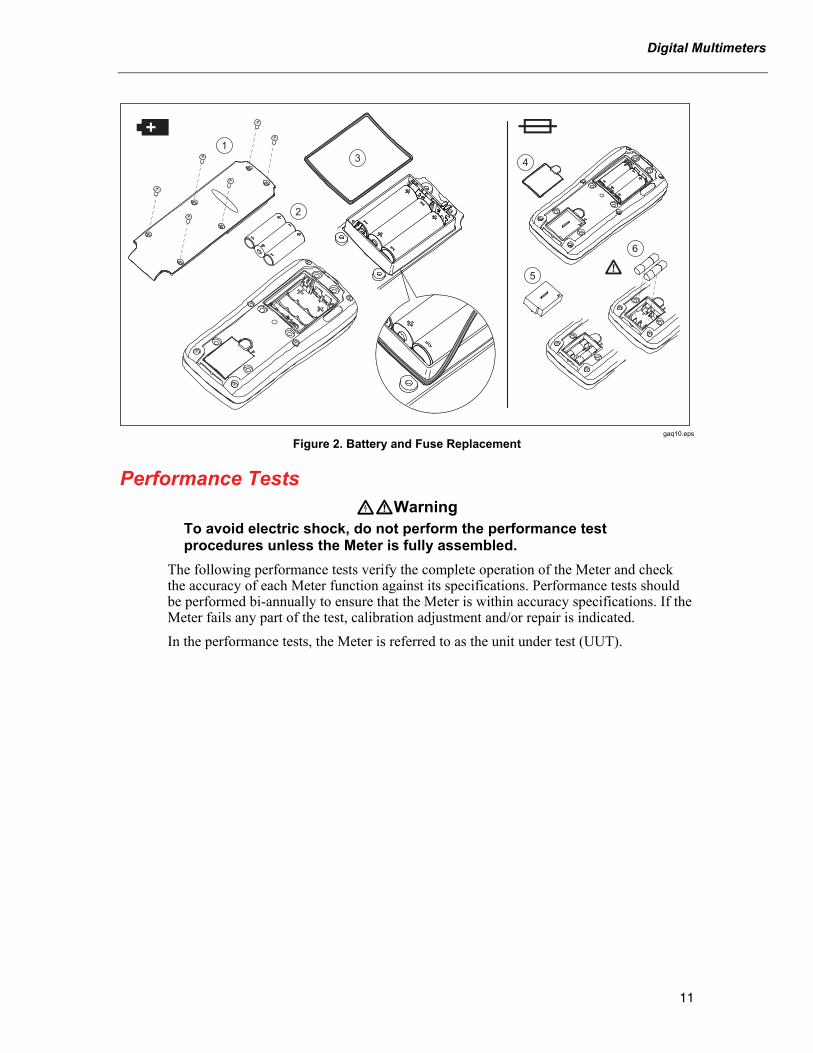
XWWarning To avoid electrical shock or personal injury, remove the test leads and any input signals before replacing the battery or fuses. To prevent damage or injury, install ONLY specified replacement fuses with the amperage, voltage, and speed ratings shown in Table 7.
Fuse Test As shown in Figure 1, with the Meter in the function, insert a test lead into the jack and place the probe tip on the other end of the test lead against the metal of the current input jack. If “LEAd” appears in the display, the probe tip has been inserted too far into the amps input jack. Back the lead out a bit until the message disappears and either OL or a resistance reading appears in the display. The resistance value should be as shown in Figure 1. If the tests give readings other than those shown, have the Meter serviced.
Touch top halfof input contacts
Good F1 fuse: 00.0 Ω to 00.5 Ω
Replace fuse: OL
Good F2 fuse: 0.995 kΩ to 1.005 kΩ
Replace fuse: OL
gaq105.eps
Figure 1. Current Fuse Test

27 II/28 II Calibration Information
10
How to Replace the Batteries
XWWarning To avoid false readings, which could lead to possible electric shock or personal injury, replace the battery as soon as the battery indicator () appears. If the display shows “batt” the Meter will not function until the battery is replaced.
Replace the battery as follows, refer to Figure 2:
1. Turn the rotary switch to OFF and remove the test leads from the terminals.
2. Remove the six Phillips-head screws from the case bottom and remove the battery door ().
Note While lifting the battery door, ensure the rubber gasket stays attached to the battery compartment barrier.
3. Remove the three batteries and replace all three with AA Alkaline batteries ().
4. Ensure the battery compartment gasket () is properly installed around the outside edge of the battery compartment barrier.
5. Replace the battery door by aligning the battery compartment barrier with battery compartment.
6. Secure the door with the six Phillips-head screws.
How to Replace the Fuses Referring to Figure 2, examine or replace the Meter's fuses as follows:
1. Turn the rotary switch to OFF and remove the test leads from the terminals.
2. Refer to step 2 under the How to Replace the Batteries section above to remove the battery door.
3. Remove the fuse compartment seal () from the fuse compartment.
4. Gently lift out the fuse compartment door () from the fuse compartment.
5. Remove the fuse by gently prying one end loose, then sliding the fuse out of its bracket ().
6. Install ONLY specified replacement fuses with the amperage, voltage, and speed ratings shown in Table 7. The 440-mA fuse is shorter than the 10-A fuse. For correct placement of each fuse, note the marking on the printed circuit board under each fuse.
7. Replace the fuse compartment door by aligning the arrow on the fuse door with the arrow on the case bottom and lowering the door into the fuse compartment.
8. Replace the fuse compartment seal by aligning the tab on the seal with the outline on the case bottom. Ensure the seal () is properly seated.
9. Refer to steps four through six under the Replacing the Batteries section above to reinstall the battery door.
Digital Multimeters
11
14
5
6
2
3
gaq10.eps
Figure 2. Battery and Fuse Replacement
Performance Tests XWWarning
To avoid electric shock, do not perform the performance test procedures unless the Meter is fully assembled.
The following performance tests verify the complete operation of the Meter and check the accuracy of each Meter function against its specifications. Performance tests should be performed bi-annually to ensure that the Meter is within accuracy specifications. If the Meter fails any part of the test, calibration adjustment and/or repair is indicated.
In the performance tests, the Meter is referred to as the unit under test (UUT).

27 II/28 II Calibration Information
12
Required Equipment Table 2 lists the equipment required to conduct a performance test on the Meter.
Table 2. Required Equipment
Recommended Equipment Measurement Function Accuracy
DC Volts 0 to 1000 V ±0.012 %
DC Current 350 μA to 2 A ±0.05 %
AC Volts 0 to 1000 V ±0.15 % @ 60 Hz to 20 kHz ±3 %
AC Current 350 μA to 2 A ±0.39 % @ 60 Hz to 1 kHz
Resistance 1 Ω to 100 MΩ ±0.06 %
Capacitance 9 to 900 μF ±0.475 %
5520A Multi-product Calibrator (or equivalent)
Frequency 19.999 to 199.99 kHz, ±0.0137 %150 mV to 6 Vrms, ±5 %
K-type Thermocouple, mini-plug on both ends
Temperature
Digital Multimeters Performance Tests
13
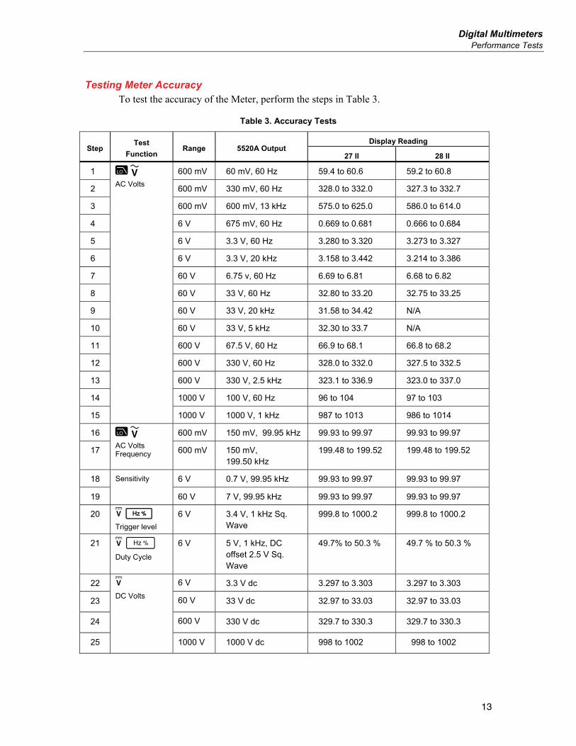
Testing Meter Accuracy To test the accuracy of the Meter, perform the steps in Table 3.
Table 3. Accuracy Tests
Display Reading Step
Test
Function Range 5520A Output
27 II 28 II
1 600 mV 60 mV, 60 Hz 59.4 to 60.6 59.2 to 60.8
2 600 mV 330 mV, 60 Hz 328.0 to 332.0 327.3 to 332.7
3 600 mV 600 mV, 13 kHz 575.0 to 625.0 586.0 to 614.0
4 6 V 675 mV, 60 Hz 0.669 to 0.681 0.666 to 0.684
5 6 V 3.3 V, 60 Hz 3.280 to 3.320 3.273 to 3.327
6 6 V 3.3 V, 20 kHz 3.158 to 3.442 3.214 to 3.386
7 60 V 6.75 v, 60 Hz 6.69 to 6.81 6.68 to 6.82
8 60 V 33 V, 60 Hz 32.80 to 33.20 32.75 to 33.25
9 60 V 33 V, 20 kHz 31.58 to 34.42 N/A
10 60 V 33 V, 5 kHz 32.30 to 33.7 N/A
11 600 V 67.5 V, 60 Hz 66.9 to 68.1 66.8 to 68.2
12 600 V 330 V, 60 Hz 328.0 to 332.0 327.5 to 332.5
13 600 V 330 V, 2.5 kHz 323.1 to 336.9 323.0 to 337.0
14 1000 V 100 V, 60 Hz 96 to 104 97 to 103
15
AC Volts
1000 V 1000 V, 1 kHz 987 to 1013 986 to 1014
16 600 mV 150 mV, 99.95 kHz 99.93 to 99.97 99.93 to 99.97
17
AC Volts Frequency 600 mV 150 mV,
199.50 kHz 199.48 to 199.52 199.48 to 199.52
18 6 V 0.7 V, 99.95 kHz 99.93 to 99.97 99.93 to 99.97
19
Sensitivity
60 V 7 V, 99.95 kHz 99.93 to 99.97 99.93 to 99.97
20 Trigger level
6 V 3.4 V, 1 kHz Sq. Wave
999.8 to 1000.2 999.8 to 1000.2
21 Duty Cycle
6 V 5 V, 1 kHz, DC offset 2.5 V Sq. Wave
49.7% to 50.3 % 49.7 % to 50.3 %
22 6 V 3.3 V dc 3.297 to 3.303 3.297 to 3.303
23 60 V 33 V dc 32.97 to 33.03 32.97 to 33.03
24 600 V 330 V dc 329.7 to 330.3 329.7 to 330.3
25
DC Volts
1000 V 1000 V dc 998 to 1002 998 to 1002
27 II/28 II Calibration Information
14
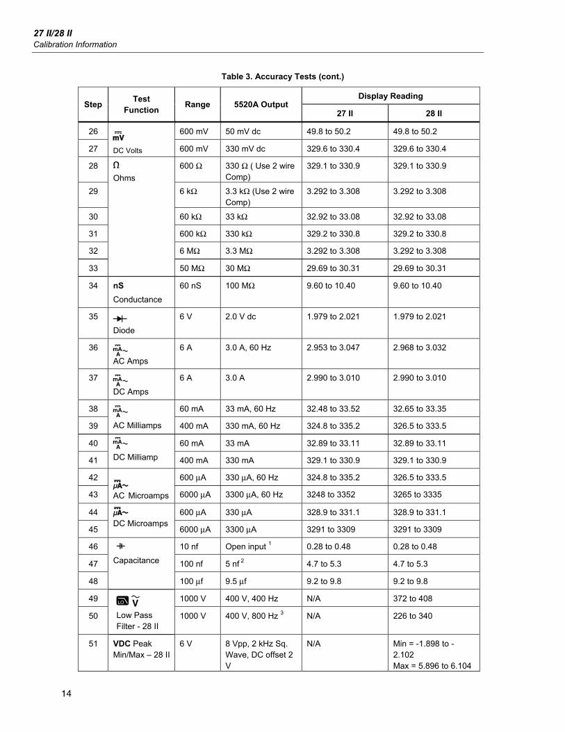
Table 3. Accuracy Tests (cont.)
Display Reading Step
Test Function
Range 5520A Output 27 II 28 II
26 600 mV 50 mV dc 49.8 to 50.2 49.8 to 50.2
27 DC Volts 600 mV 330 mV dc 329.6 to 330.4 329.6 to 330.4
28 600 Ω 330 Ω ( Use 2 wire Comp)
329.1 to 330.9 329.1 to 330.9
29 6 kΩ 3.3 kΩ (Use 2 wire Comp)
3.292 to 3.308 3.292 to 3.308
30 60 kΩ 33 kΩ 32.92 to 33.08 32.92 to 33.08
31 600 kΩ 330 kΩ 329.2 to 330.8 329.2 to 330.8
32 6 MΩ 3.3 MΩ 3.292 to 3.308 3.292 to 3.308
33
Ohms
50 MΩ 30 MΩ 29.69 to 30.31 29.69 to 30.31
34 nS
Conductance
60 nS 100 MΩ 9.60 to 10.40 9.60 to 10.40
35 Diode
6 V 2.0 V dc 1.979 to 2.021 1.979 to 2.021
36 AC Amps
6 A 3.0 A, 60 Hz 2.953 to 3.047 2.968 to 3.032
37 DC Amps
6 A 3.0 A 2.990 to 3.010 2.990 to 3.010
38 60 mA 33 mA, 60 Hz 32.48 to 33.52 32.65 to 33.35
39
AC Milliamps 400 mA 330 mA, 60 Hz 324.8 to 335.2 326.5 to 333.5
40 60 mA 33 mA 32.89 to 33.11 32.89 to 33.11
41
DC Milliamp 400 mA 330 mA 329.1 to 330.9 329.1 to 330.9
42 600 μA 330 μA, 60 Hz 324.8 to 335.2 326.5 to 333.5
43 AC Microamps 6000 μA 3300 μA, 60 Hz 3248 to 3352 3265 to 3335
44 600 μA 330 μA 328.9 to 331.1 328.9 to 331.1
45
DC Microamps
6000 μA 3300 μA 3291 to 3309 3291 to 3309
46 10 nf Open input 1 0.28 to 0.48 0.28 to 0.48
47 100 nf 5 nf 2 4.7 to 5.3 4.7 to 5.3
48
E
Capacitance
100 μf 9.5 μf 9.2 to 9.8 9.2 to 9.8
49 1000 V 400 V, 400 Hz N/A 372 to 408
50
Low Pass Filter - 28 II
1000 V 400 V, 800 Hz 3 N/A 226 to 340
51 VDC Peak Min/Max – 28 II
6 V 8 Vpp, 2 kHz Sq. Wave, DC offset 2 V
N/A Min = -1.898 to -2.102 Max = 5.896 to 6.104

Digital Multimeters Calibration Adjustments
15
Table 3. Accuracy Tests (cont.)
Display Reading Step
Test Function
Range 5520A Output 27 II 28 II
52 0 °C N/A -1.0 to 1.0
53
mVdc Temperature 4 – 28 II
100 °C N/A 98.0 to 102.0
54 Press backlight button
Backlight comes on
Backlight comes on
55 Press backlight button
Backlight intensifies
Backlight intensifies
56
Backlight
Press backlight button
Backlight goes off Backlight goes off
[1] Remove test leads from unit.
[2] Use REL to compensate for internal Meter and lead capacitance (must disconnect test leads from calibrator before pushing REL)
[3] The Meter accuracy is not specified at this input signal frequency with Low-pass filter selected. The display reading shown, checks that the Low-pass filter is active and follows an expected roll-off curve.
[4] To ensure accurate measurement, the Meter and thermocouple adapter must be at the same temperature. After connecting the thermocouple adapter to the Meter allow for reading to stabilize before recording display reading.
Calibration Adjustments Perform the Calibration Adjustment Procedure if the Meter fails any performance tests. If the adjustment routine is discontinued prior to completion, no changes are made to the calibration contstants that are stored in memory. The following is an explanation of the pushbutton features and requirements to enter the CAL mode.
Cal Mode Pushbutton Functions • The CAL mode will be initiated by holding down the MINMAX pushbutton at power
up and entering a four digit password.
• The AutoHOLD pushbutton will act as an "ENTER" key and will advance through the CAL initiation and adjustment procedure steps.
• The pushbuttons are used to select a four-digit password.
During initiation of the CAL mode, a display count will show how many times calibration constants have been written to memory.
Entering and Displaying the Four-Digit Password When the Meter was manufactured it was given a default password of 1234. The following pushbuttons are used to select the password. Each pushbutton represents the indicated digit.
Yellow = 1 MINMAX = 2 RANGE = 3 AutoHOLD = 4
Backlight =5 Continuity = 6 REL = 7 Hz = 8
After selecting the password the user has two choices:
Pressing AutoHOLD will display "C-01" which indicates correct password and successful entry. You may now proceed with the first calibration step.
Pressing RANGE will display "----", which indicates correct password, proceed to select a new password.
If the password is incorrect, the concluding AutoHOLD or RANGE pushbutton press will instead cause the Meter to double beep and the display will show "????". The password entry process was unsuccessful and can be tried again or you may exit this mode by turning the Meter off.
27 II/28 II Calibration Information
16
Changing the Password To change the password in the Meter:
1. Turn the Meter Rotary Switch from OFF to VAC mode while holding down the MINMAX pushbutton at the same time. The Meter will display Y CAL.
2. Press the AutoHOLD pushbutton twice. The display should show "????"
3. Using the pushbuttons select the old password (do not use AutoHOLD to save the password)
4. Press the RANGE pushbutton. The Meter should display "_ _ _ _" .
5. Use the pushbuttons to select a desired new password.
6. Press AutoHOLD to save the new password.
Restoring the Default Password If the password has been forgotten, the default password (1234) can be restored by performing the following:
1. Turn the rotary switch of the Meter to OFF.
2. Remove the bottom case and bottom shield of the Meter.
3. Check the revision number on the PCB. Board revision location is identified in Figures 3 and 4 below.
Digital Multimeters Calibration Adjustments
17
If the revision number is 010:
4. Remove the PCB from the top case.
5. Apply power to the PCB by clipping on a dc voltage between 3.5 V and 5 V at the test points marked “+” and “-” at the edge of the board. See Figure 3.
5
TP2TP1
S7
S11
3.5 - 5 V
6
6
7
8
7
2X-2- 3001 REV 010
2X-2- 3001 REV 010
gaq101.eps
Figure 3. Revision 010 Board Layout
6. While shorting across keypad button S7, turn the rotary switch one position clockwise. See Figure 3.
7. Short across keypad button S11. See Figure 3.
8. Turn the rotary switch one position counterclockwise, back to its original position.
9. The default password is now restored.
10. Reassemble the Meter before performing adjustments or testing.
27 II/28 II Calibration Information
18
If the revision number is 011 or higher:
4. Apply power to the PCB by clipping on a dc voltage between 3.5 V and 5 V at the test points marked “+” and “-” at the edge of the board. See Figure 4.
S11
4
3.5 - 5 V
5
6
S11
2X-2- 3001 REV 011
2X-2- 3001 REV 011
gaq102.eps
Figure 4. Revision 011 Board Layout
5. Turn the rotary switch from OFF to while holding down MIN MAX at the same time. The Meter should display CAL.
6. Short across keypad button S11 on the back of the PCB. See Figure 4. The Meter should beep.
7. Turn the rotary switch one position counterclockwise, back to the OFF position.
8. The default password is now restored.
9. Reassemble the Meter before performing adjustments or testing.

Digital Multimeters Calibration Adjustments
19
Other Pushbutton Functions Table 4 list the button on the Meter and describes what the button does when pressed after the password has been entered and pressed.
Table 4. Pushbutton Functions During Cal Mode
Button Cal Mode Description
(yellow)
Press and hold to test the present function. The measurement is not calibrated so it may be inaccurate. This is normal.
Press and hold to display the required input level.
Press and hold to display the frequency of the input signal.
Press to store the new calibration adjustment value and advance to the next step. This pushbutton is also used to exit calibration adjustment mode after the calibration adjustment sequence is complete.
Calibration Adjustment Procedure In the following procedure, some adjustment steps take longer to execute than others (10 to 15 Seconds). For some of these steps the Meter gives a double beep to indicate completion. Not all steps have this feature.
1. Turn the rotary switch of the Meter from OFF to while holding down at the same time. The Meter should display CAL.
2. Press once to see the number of calibrations that have been completed. Press again to enable password entry. The Meter should display "????".
3. Use the keypad pushbuttons to enter the existing password and press . The Meter should display Y .
4. Apply the value listed in Table 5 or 6 for each calibration step, and/or (optional) press the to display the required input signal level and press to display the required input signal frequency.
Note After pressing , wait until the step number advances before changing the calibrator source or turning the rotary switch of the Meter. If the reference source input is not within an anticipated range of the required value, the Meter will emit a double beep and not allow completion of the step. Set the calibrator to standby prior to changing the function switch position and or after completing adjustment of each function. If the calibration adjustment is not completed correctly, the Meter will not operate correctly.
27 II/28 II Calibration Information
20
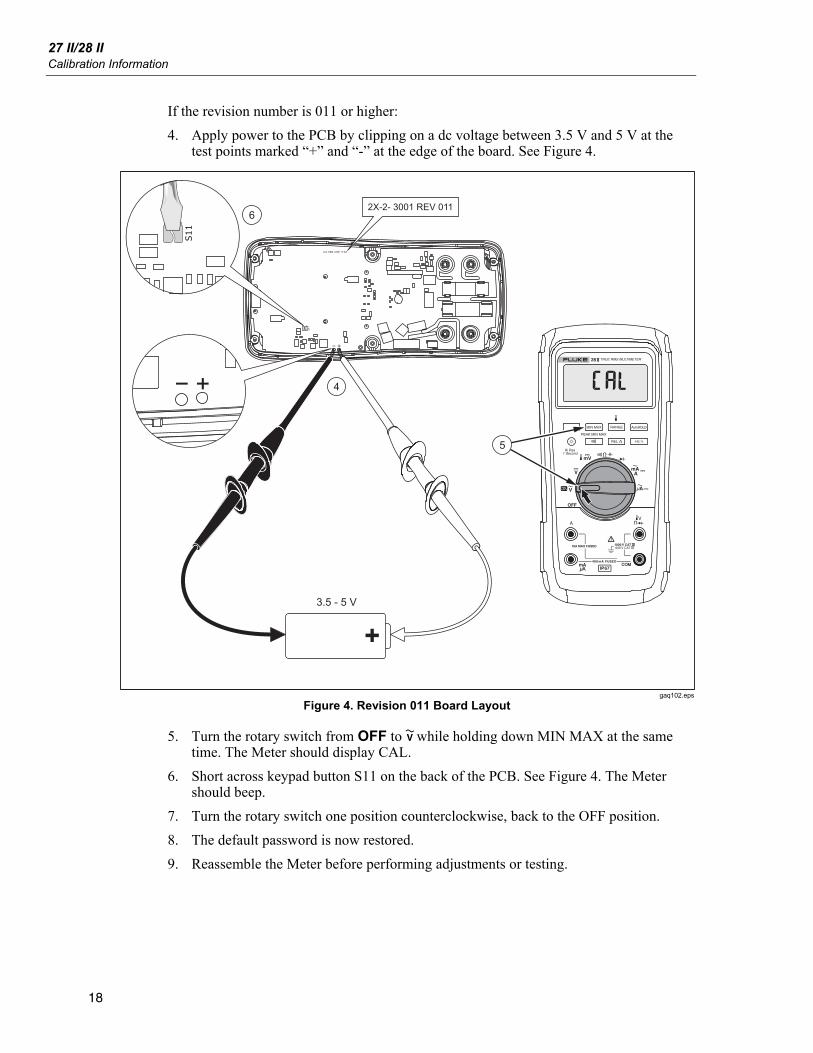
Table 5. Fluke 27 II Calibration Adjustment Steps
Function (Switch Position)
Adjustment Step Input Value
C-01 0 mV, 0 Hz
C-02 6.0 mV, 60 Hz
C-03 60.0 mV, 60 Hz
C-04 600.0 mV, 60 Hz
C-05 600.0 mV, 20 kHz
C-06 6.0 V, 60 Hz
C-07 6.0 V, 20 kHz
C-08 60.0 V, 60 Hz
C-09 60.0 V, 20 kHz
C-10 600.0 V, 60 Hz
(AC Volts)
C-11 600.0 V, 10 kHz
C-12 6.0 V
C-13 60.0 V (DC Volts)
C-14 600.0 V
C-15 600.0 mV (DC Millivolts) C-16 60.00 mV
C-17 600.0 Ω
C-18 6.000 kΩ
C-19 60.00 kΩ
C-20 600.0 kΩ
C-21 6.000 MΩ
C-22 0.000 Ω
(Ohms)
C-23 50.0 MΩ
(Diode Test)
C-24 3.000 V
C-25 0.000 A, 0 Hz
C-26 60.0 mA 60 Hz
C-27 6.0 A, 60 Hz
(Amps)
C-28 6.0 A, 0 Hz
C-29 0.0 mA, 0 Hz
C-30 600.0 μA, 60 Hz
C-31 6.0 mA, 60 Hz
C-32 60.0 mA, 60 Hz
C-33 400.0 mA, 60 Hz
C-34 60.0 mA, 0 Hz
(Milliamps)
C-35 400.0 mA, 0 Hz

Digital Multimeters Calibration Adjustments
21
Table 5. Fluke 27 II Calibration Adjustment Steps (cont.)
Function (Switch Position)
Adjustment Step Input Value
C-36 0.0 μA ac, 0 Hz
C-37 30.0 μA, 60 Hz
C-38 60.0 μA. 60 Hz
C-39 600.0 μA, 60 Hz
C-40 6000.0 μA, 60 Hz
C-41 600.0 μA, 0 Hz
(Microamps)
C-42 6000.0 μA, 0 Hz
Table 6. Fluke 28 II Calibration Adjustment Steps
Function (Switch Position)
Adjustment Step Input Value
C-01 600.0 mV, 60 Hz
C-02 600.0 mV, 20 kHz
C-03 6.000 V, 60 Hz
C-04 6.000 V, 20 kHz
C-05 60.00 V, 60 Hz
C-06 60.00 V, 20 kHz
C-07 600.0 V, 60 Hz
(AC Volts)
C-08 600.0 V, 10 kHz
C-09 6.000 V
C-10 60.00 V (DC Volts)
C-11 600.0 V
C-12 600.0 mV (DC Millivolts) C-13 60.00 mV
C-14 600.0 Ω
C-15 6.000 kΩ
C-16 60.00 kΩ
C-17 600.0 kΩ
C-18 6.000 MΩ
C-19 0.000 Ω
(Ohms)
C-20 50.0 MΩ
(Diode Test) C-21 3.000 V
C-22 6.000 A, 60 Hz (Amps) C-23 6.000 A dc
C-24 60.00 mA, 60 Hz
C-25 400.0 mA, 60 Hz
C-26 60.00 mA dc
(Amps)
C-27 400.0 mA dc

27 II/28 II Calibration Information
22
Table 6. Fluke 28 II Calibration Adjustment Steps (cont.)
Function (Switch Position)
Adjustment Step Input Value
C-28 600.0 μA, 60 Hz
C-29 6000 μA, 60 Hz
C-30 600.0 μA dc
(Microamps)
C-31 6000 μA dc
Disassembling the Meter To disassemble the Meter:
1. Use a Philips screwdriver to remove the six battery-door screws (H1).
2. Lift up the battery door (MP1) at the top end of the Meter and remove it from the case back.
3. Remove three AA batteries.
4. Remove the fuse access door (MP4).
5. Remove the fuse cap (MP5).
6. Use a Philips screwdriver to remove the bottom-case screws (H2) with their 0-rings (H3).
7. Separate the bottom case (MP6) from the top case (MP19).
8. Use a Philips screwdriver to remove the bottom-shield screw (H4).
9. Remove the bottom shield (MP9) from the Meter.
10. Use a Philips screwdriver to remove four PCA input screws (H5).
11. Use a Philips screwdriver to remove six PCA screws (H4) from the board.
12. Remove the PCA from the top case.
13. Remove the top shield (MP13) from the top case.
14. Remove the elastomerics (MP10) from the top shield.
15. Unsnap mask (MP15) from the top shield (MP13).
16. Remove the LCD (DS1) from the top shield.
17. Remove the backlight (MP14) from the top shield.
18. Remove the keypad (MP18) from the top case.
19. Remove the RSOB spacer (MP16) from the top case.
20. Remove the E-clip holding the spring detent (MP17) from the top case.
21. Remove the sprint detent from the top case.
22. Remove the knob (MP20) from the top case.

Digital Multimeters Reassembling the Meter
23
Reassembling the Meter Note
Before reassembling the Meter, read the How to Retain the IP67 Rating section first.
To reassemble the Meter, perform the disassembly steps in reverse order.
How to Retain the IP67 Rating The following items identify parts of the Meter that can compromise the IP67 rating by leaking if assembly instructions are not followed carefully.
1. Knob: The knob has an overmolded seal that fits tight against the top case. This area must be lubed and the lube must be spread evenly around the seal area.
2. E-clip: Make sure it is installed correctly.
3. Keypad: The keypad must be seated correctly and all six board screws tightened to 6 in-lbs torque.
4. Bottom case gasket: The gasket must be installed so that the gasket does not have any twists, bends, waves, etc. The gasket must be completely flat in the bottom case groove. This can be accomplished by using a modified top case to push the gasket into position.
5. Battery door gasket: Place over battery compartment walls and push each corner down as far as they will go. Install battery door screws with 6 in-lbs torque.
6. Fuse access door: Place onto bottom case and wiggle it to make sure it is fully seated. Install the battery door screws with 6 in-lbs torque.
7. Case screw o-ring: Torque case screws to 12 in-lbs torque. Verify that the o-rings are not sticking out of the sides of the screw head.
Note If you want to ensure your Meter meets the IP67 rating, return the Meter to a qualified Fluke Service center.

27 II/28 II Calibration Information
24
Replacement Parts Table 7 lists the Meter’s replaceable parts identified in Figure 5.
MP20
MP19
MP18
MP15
DS1
MP14
MP10
MP9
H4 (7)
MP7
MP8 (2)
MP6
MP2
MP3 (2)
BT1 (3)
MP1
MP4
H1 (6)
MP5
H4 (7)
H5 (4)
F1
F2
MP13
MP11MP12
MP16
MP17
H2 (6)H3 (6)
gaq106.eps
Figure 5. Exploded View of Meter
Digital Multimeters Replacement Parts
25
Table 7. Replaceable Parts List
Item Description Part
Number Qty.
BT1 BATTERY,PRIMARY,ZN-MNO2,1.5V,2.24AH,15A,LR6,ALKALINE,AA,14X50MM,BULK 376756 3
DS1 LCD,4.5 DIGIT,TN,TRANSFLECTIVE,BAR GRAPH,OSPR80,,FLUKE-87-5 2065213 1
F1 WFUSE,11A,1000V,FAST.406INX1.5IN,BULK 803293 1
F2 WFUSE,.440 A,1000V,FAST.406INX1.5IN,BULK 943121 1
H1 SCREW,M3X0.5,6MM,PAN,PHILLIPS,STEEL,ZINC-BLACK CHROMATE 2032792 6
H2 SCREW,5-14,.750,PAN,HEXALOBULAR,STEEL,ZINC-BLK CHROMATE,BLUNT PT,THREAD FORM 1558745 6
H3 O-RING,NITRILE,INT LUBE,SHORE A 70,AS 568A-006,.114 ID,.070 W 705947 6
H4 SCREW,4-14,.510,PAN,PHILLIPS,STEEL,ZINC-CHROMATE,THREAD CUT 853668 7
H5 SCREW,M3X0.5,6MM,PAN,PHILLIPS,STEEL,ZINC-CHROMATE 2743764 4
MP1 FLUKE-2X-2-2010,BATTERY DOOR, WITHOUT BATTERY CONTACTS 3321030 1
MP2 FLUKE-2X-II-8007,GASKET, BATT DOOR, FLUKE 27-II AVG AND FLUKE 28-II TRMS METERS 3439087 1
MP3 FLUKE 89-4-8012 ,BATTERY CONTACT, DUAL 666435 2
MP4 FLUKE-2X-2-2014,FUSE ACCESS DOOR, 27-2 AVG AND 28-2 TRMS MULTIMETER 3400480 1
MP5 FLUKE-2X-2-2015,FUSE CAP 3440546 1
MP6 FLUKE-2X-2-2004,CASE, BOTTOM WITHOUT BATTERY CONTACTS 3320869 1
MP7 FLUKE 2X-II-8006,GASKET, TOP CASE, FLUKE-27-II AVG AND FLUKE-28-II TRMS METERS 3439079 1
MP8 SHENGUANG-8012,BATTERY CONTACT SHENGUANG 3324731 2
MP9 FLUKE-2X-2-8002,BOTTOM SHIELD, FLUKE 27-2 AVG / FLUKE 28-2 TRMS MULTIMETER 3371942 1
MP10 CONNECTOR,ELASTOMERIC,.375 HIGH,.10 THICK,1.59 LONG,BULK 3440661 2
MP11 FLUKE-17X-8001,CONTACT, RSOB 3084560 4
MP12 FLUKE 87-5-2009,HOUSING, RSOB 2073945 1
MP13 FLUKE-2X-2-8001,TOP SHIELD, FLUKE 27-2 AVG / FLUKE 28-2 TRMS MULTIMETER 3371939 1
MP14 FLUKE-2X-2-8009,BACKLIGHT, FLUKE 27II / FLUKE 28II MULTIMETER 3471251 1
27 II/28 II Calibration Information
26
Table 7. Replaceable Parts List (cont.)
Item Description Part
Number Qty.
FLUKE-27-2-2501-04,MASK, LCD (PAD XFER), (for 27-2) 3400020 1 MP15
FLUKE-28-2-2501-05,MASK, LCD (PAD XFER) (for 28-2) 3400047 1
MP16 FLUKE-2X-2-2007,SPACER, RSOB 3320891 1
MP17 FLUKE-2X-2-2008,DETENT, SPRING 3320905 1
MP18 FLUKE-2X-8003,KEYPAD, FLUKE 27-2 AND FLUKE 28-2 3359962 1
FLUKE-27-2-2501,TOP CASE, PAD XFER (For 27-2) 3441368 1 MP19
FLUKE-28-2-2502, TOP CASE, PAD XFER (for 28-2) 3320857 1
MP20 FLUKE-2X-2-2009,ROTARY KNOB 3320922 1
Not Shown FLUKE-2X-2-2011,HOLSTER w/Tilt Stand 3321048 1
Not Shown TL75-4201 ,TEST LEADS 855742 1
Not Shown 80BK-A-8001, TYPE K THERMOCOUPLE ASSEMBLY (for 28-2) 2747900 1
Not Shown FLUKE 87-5-8009,TILTSTAND 2074040 1
Not Shown 27 II / 28 II Getting Started Manual 3368142 1
Not Shown 27 II / 28 II Users Manual CD 3368139 1

Digital Multimeters Replacement Parts
27
Lifetime Limited Warranty Each Fluke 20, 70, 80, 170, 180 and 280 Series DMM will be free from defects in material and workmanship for its lifetime. As used herein, “lifetime” is defined as seven years after Fluke discontinues manufacturing the product, but the warranty period shall be at least ten years from the date of purchase. This warranty does not cover fuses, disposable batteries, damage from neglect, misuse, contamination, alteration, accident or abnormal conditions of operation or handling, including failures caused by use outside of the product’s specifications, or normal wear and tear of mechanical components. This warranty covers the original purchaser only and is not transferable. For ten years from the date of purchase, this warranty also covers the LCD. Thereafter, for the lifetime of the DMM, Fluke will replace the LCD for a fee based on then current component acquisition costs.
To establish original ownership and prove date of purchase, please complete and return the registration card accompanying the product, or register your product on http://www.fluke.com. Fluke will, at its option, repair at no charge, replace or refund the purchase price of a defective product purchased through a Fluke authorized sales outlet and at the applicable international price. Fluke reserves the right to charge for importation costs of repair/replacement parts if the product purchased in one country is sent for repair elsewhere.
If the product is defective, contact your nearest Fluke authorized service center to obtain return authorization information, then send the product to that service center, with a description of the difficulty, postage and insurance prepaid (FOB Destination). Fluke assumes no risk for damage in transit. Fluke will pay return transportation for product repaired or replaced in-warranty. Before making any non-warranty repair, Fluke will estimate cost and obtain authorization, then invoice you for repair and return transportation.
THIS WARRANTY IS YOUR ONLY REMEDY. NO OTHER WARRANTIES, SUCH AS FITNESS FOR A PARTICULAR PURPOSE, ARE EXPRESSED OR IMPLIED. FLUKE SHALL NOT BE LIABLE FOR ANY SPECIAL, INDIRECT, INCIDENTAL OR CONSEQUENTIAL DAMAGES OR LOSSES, INCLUDING LOSS OF DATA, ARISING FROM ANY CAUSE OR THEORY. AUTHORIZED RESELLERS ARE NOT AUTHORIZED TO EXTEND ANY DIFFERENT WARRANTY ON FLUKE’S BEHALF. Since some states do not allow the exclusion or limitation of an implied warranty or of incidental or consequential damages, this limitation of liability may not apply to you. If any provision of this warranty is held invalid or unenforceable by a court or other decision-maker of competent jurisdiction, such holding will not affect the validity or enforceability of any other provision.
Fluke Corporation P.O. Box 9090 Everett, WA 98206-9090 U.S.A.
Fluke Europe B.V. P.O. Box 1186 5602 BD Eindhoven The Netherlands
5/07

27 II/28 II Calibration Information
28