Embed Size (px)
Citation preview

CONTENTS Sections :- Page 1. Installation 2 2. Open Program, Create Cause Effect File 3
• Adding / deleting panels • Folder management • File naming
3. Main Editor Window for Configuring Cause and Effect 7 1.View Menu. 7 2.Panal Layout Menu 8 3.Special Functions 9 4. Sensitivity 12 5. Sensitivity - Day Night: Settings 13 6. Select Output 14 7. Allocate Zone/Groups 22 8. Edit texts 23 9. Print 24 10. DOWNLOADING TO PANEL 25 APPENDIX / TIPS 31
Installation PC requirements :- PC tower – Pentium 2 – 4 (500MHz and Above) 128Mb Ram Floppy Disk Drive , CD-ROM or If downloading from Internet ( Modem ) Hard Disk = 2GB At Least
Software : Operating Systems Win 98 SE, Win2000, Windows ME, Windows NT, Win XP
Software Applications : If C&E was downloaded from Internet . User will need Win RAR Application to Unzip/unRAR downloaded Cause and
Effect file. Installation Guide setup. Click on Setup. If file is in Win RAR format. Run Win RAR , Then unzip/un compress file to a folder then click setup
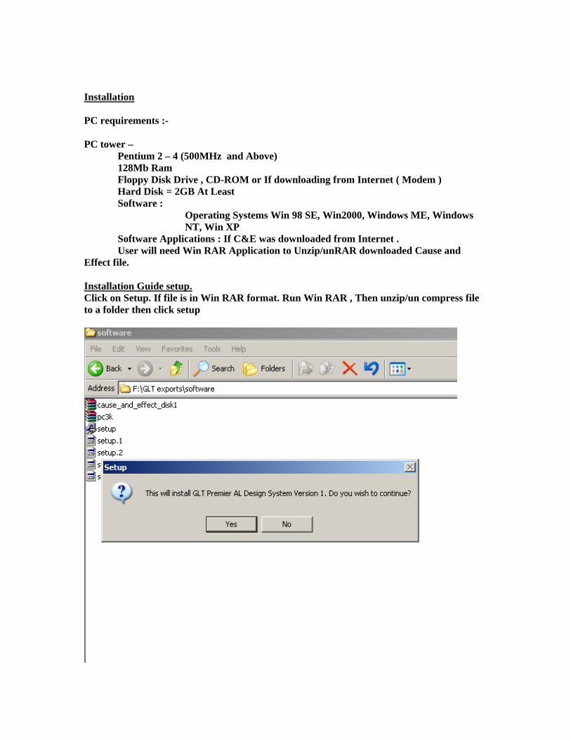
Install and follow instructions. Accept License and choose program folder path.
Once Installed, Run program either via shortcut or from programs Menu.
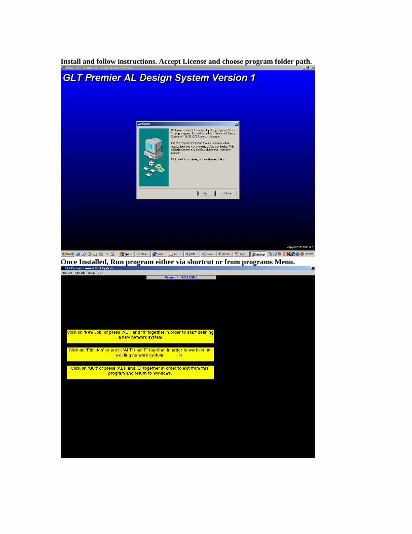
3. CAUSE/EFFECT PROGRAMMING SYSTEM CABLE CONNECTIONS FOR DOWNLOAD 1.PC to Premier AL / GLOBAL NET REP Null Modem Cable 2.PC USB PORT to Premier AL or PC USB PORT to Premier AL GLOBAL NETWORK REPEATER
USB to Serial COMM D-TYPE Converter Box / Unit + 1 USB CABLE + 1 NULL MODEM CABLE
This document is a description of the cause/effect programming system for the Premier AL network system. The equipment is currently limited to two panel types, the Premier AL Global network repeater and the Premier AL 1-4 loop analogue addressable panel. Each job designed on this system will have a 5 digit contract number that is included in all of the file-names used for that job, and is also the name of the directory where the files are stored, whether on a hard disk or a floppy disk. There will also be a twenty character contract name to be specified, together with a twenty character name for each panel on the system. Once a job has been fully designed, a wide variety of printouts can be generated for reference, and a hex file will be generated for each appropriate panel that can then be downloaded into that panel directly from a computer, or may be programmed into an appropriate EPROM or EEPROM first, and then the EPROM taken to the panel and installed. First Create A JOB FILE .If no existing File/ Panel Cause And Effect file is present. Select 1. New Job. Fill in Fields , i.e job name , file number and folder path etc
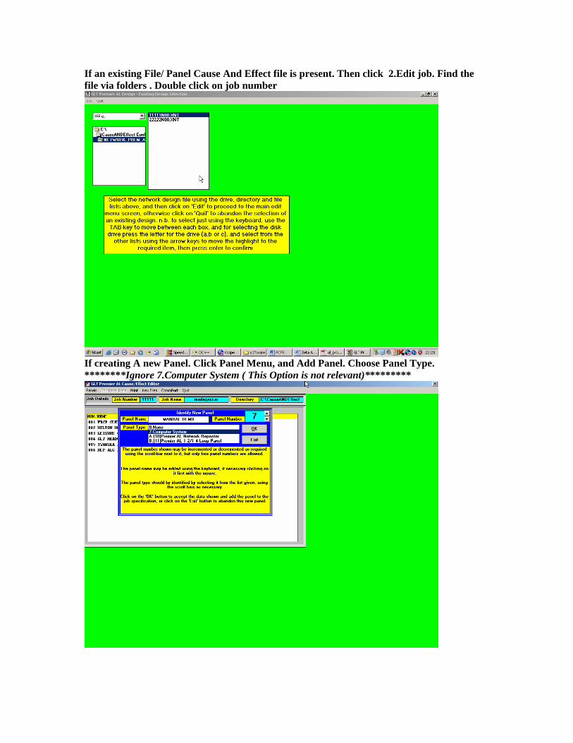
If an existing File/ Panel Cause And Effect file is present. Then click 2.Edit job. Find the file via folders . Double click on job number
If creating A new Panel. Click Panel Menu, and Add Panel. Choose Panel Type. ********Ignore 7.Computer System ( This Option is not relevant)*********

Once the Panel Has been created, it now needs editing Highlight Panel in Existing panel Window and Click Edit Panel Data Menu
EDIT PANEL DATA MENU BRINGS UP A NEW WINDOW. WHICH IS WHERE THE USER CAN CONFIGURE CAUSE AND EFFECT
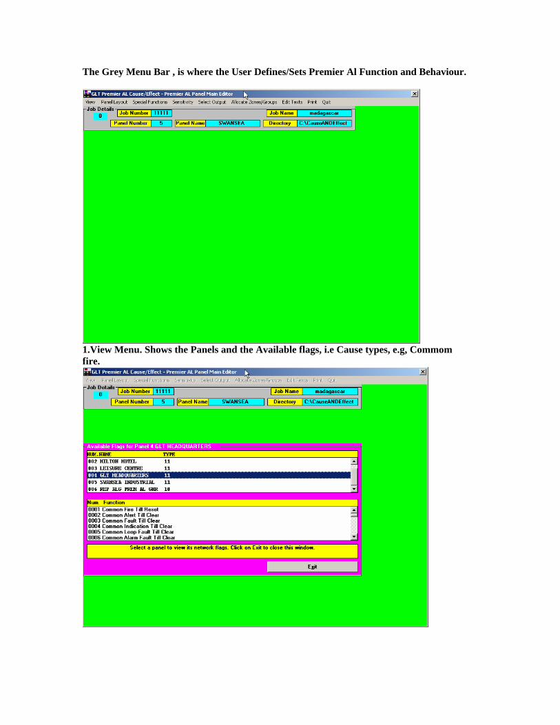
The Grey Menu Bar , is where the User Defines/Sets Premier Al Function and Behaviour.
1.View Menu. Shows the Panels and the Available flags, i.e Cause types, e.g, Commom fire.

2.Panal Layout Menu. User defines, Number of Loops, Repeaters(LOCAL), I/O Boards.etc Use the arrow keys, to define the number of repeater s, i/o boards , loop cards.
3.11.Special Functions > Time Functions > Panel Delay. User defines Delay Duration and Start / Stop Time.
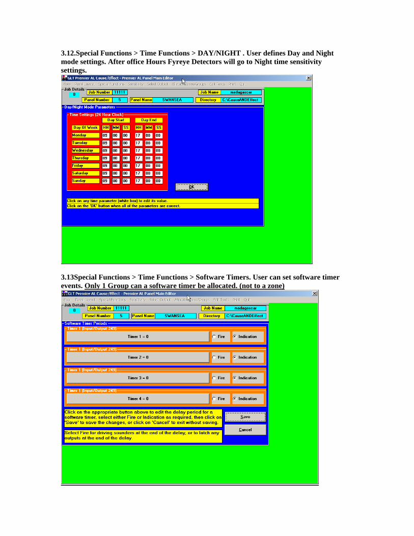
3.12.Special Functions > Time Functions > DAY/NIGHT . User defines Day and Night mode settings. After office Hours Fyreye Detectors will go to Night time sensitivity settings.
3.13Special Functions > Time Functions > Software Timers. User can set software timer events. Only 1 Group can a software timer be allocated. (not to a zone)

3.21Special Functions > Time Functions > Access code. Type Old code to enter new code
3.31Special Functions > Time Functions > Network Responses. User text is recommended. User defines if or how a panel responds to network flags, causes, events etc
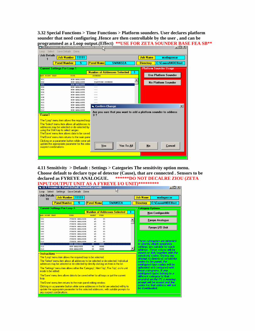
3.32 Special Functions > Time Functions > Platform sounders. User declares platform sounder that need configuring .Hence are then controllable by the user , and can be programmed as a Loop output.(Effect) **USE FOR ZETA SOUNDER BASE FEA SB**
4.11 Sensitivity > Default : Settings > Categories The sensitivity option menu. Choose default to declare type of detector (Cause), that are connected . Sensors to be declared as FYREYE ANALOGUE. ******DO NOT DECALRE ZIOU (ZETA INPUT/OUTPUT UNIT AS A FYREYE I/O UNIT)*********

4.12 Sensitivity > Default : Settings > Alert trips User can set alert trips(pre-alarm condition), via the settings menu.
4.13. Sensitivity > Default : Settings > Fire trips. User can program fire trips settings for each individual sensor(cause)
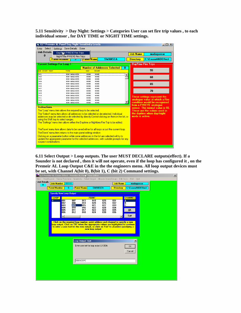
5.11 Sensitivity > Day Night: Settings > Categories User can set fire trip values , to each individual sensor , for DAY TIME or NIGHT TIME settings.
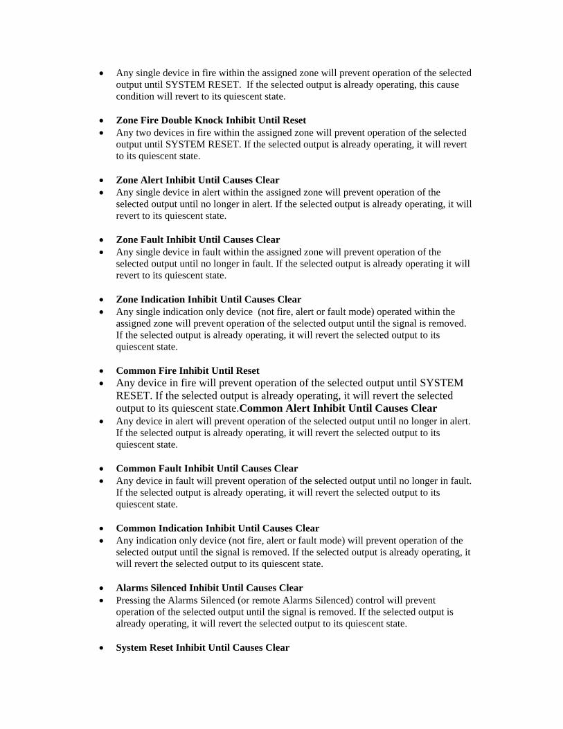
6.11 Select Output > Loop outputs. The user MUST DECLARE outputs(effect). If a Sounder is not declared , then it will not operate, even if the loop has configured it , on the Premeir AL Loop Output C&E in the the engineers menu. All loop output devices must be set, with Channel A(bit 0), B(bit 1), C (bit 2) Command settings.

Once a loop out put is declared. Then the User can manipulate/program its behaviour(effect). Highlight the loop output and CLICK the CAUSES Button.
Choose either Local for a Single Panel. Or Network for a network of Panels. ***WARNING.MAKE SURE YOU ARE FULLY CAPABLE AND UNDERSTAND CAUSE AND EFFECT. RECORD STATE OF CAUSES > AND RECORD NEW CAUSES CREATED, SO THAT IT CAN BE DELETED IF PANEL DOES NOT OPERATE OR GIVES A FAULT) USER MUST RETRACE STEPS, IN CASE USER HAS TO DELETE A BADLY CREATED CAUSE AND EFFECT*** CHOOSING LOCAL WILL BRING UP ARANGE OF FLAG?CAUSE TYPES WHICH ARE DEFINED :-
• Zone Fire Single Knock Operate Until Reset • One single device in fire within the assigned zone will cause the selected output to
operate until SYSTEM RESET.
• Zone Fire Single Knock Operate Until Silence • As above except operates until SILENCE ALARMS is pressed.
• Zone Fire Double Knock Operate Until Reset • Two devices in fire within the assigned zone will cause the selected output to operate
until SYSTEM RESET.
• Zone Fire Double Knock Operate Until Silence • As above except operates until SILENCE ALARMS is pressed.
• Zone Fire Triple Knock Operate Until Reset

• Three devices in fire within the assigned zone will cause the selected output to operate until SYSTEM RESET.
• Zone Fire Triple Knock Operate Until Silence • As above except operates until SILENCE ALARMS is pressed.
• Zone Alert Operate Until Causes Clear • Any single device in alert within the assigned zone will cause the selected output to
operate until no longer in alert.
• Zone Fault Operate Until Causes Clear • Any single device in fault within the assigned zone will cause the selected output to
operate until no longer in fault.
• Zone Indication Operate Until Causes Clear • Any single indication only device (not fire, alert or fault mode) operated within the
assigned zone will cause the selected output to operate until the signal is removed.
• Common Fire Operate Until Reset • Any device in fire will cause the selected output to operate until SYSTEM RESET.
• Common Fire Operate Until Silence • As above except until SILENCE ALARMS is pressed.
• Common Alert Operate Until Causes Clear • Any device in alert will cause the selected output to operate until no longer in alert.
• Common Fault Operate Until Causes Clear • Any device in fault will cause the selected output to operate until no longer in fault.
• Common Indication Operate Until Causes Clear • Any indication only device (not fire, alert or fault mode) operated will cause the
selected output to operate until the signal is removed.
• Alarms Silenced Operate Until Causes Clear • Pressing the Alarms Silenced (or remote Alarms Silenced) control will cause the
selected output to operate until the signal is removed.
• System Reset Operate Until Causes Clear • Pressing the System Reset (or remote System Reset) control will cause the selected
output to operate for 10-15 seconds until the signal is removed.
• Evacuate Operate Until Causes Clear • Pressing the Evacuate (or remote Evacuate) control will cause the selected output to
operate until the system is no longer in Evacuate.
• Zone Fire Single Knock Inhibit Until Reset
• Any single device in fire within the assigned zone will prevent operation of the selected output until SYSTEM RESET. If the selected output is already operating, this cause condition will revert to its quiescent state.
• Zone Fire Double Knock Inhibit Until Reset • Any two devices in fire within the assigned zone will prevent operation of the selected
output until SYSTEM RESET. If the selected output is already operating, it will revert to its quiescent state.
• Zone Alert Inhibit Until Causes Clear • Any single device in alert within the assigned zone will prevent operation of the
selected output until no longer in alert. If the selected output is already operating, it will revert to its quiescent state.
• Zone Fault Inhibit Until Causes Clear • Any single device in fault within the assigned zone will prevent operation of the
selected output until no longer in fault. If the selected output is already operating it will revert to its quiescent state.
• Zone Indication Inhibit Until Causes Clear • Any single indication only device (not fire, alert or fault mode) operated within the
assigned zone will prevent operation of the selected output until the signal is removed. If the selected output is already operating, it will revert the selected output to its quiescent state.
• Common Fire Inhibit Until Reset • Any device in fire will prevent operation of the selected output until SYSTEM
RESET. If the selected output is already operating, it will revert the selected output to its quiescent state.Common Alert Inhibit Until Causes Clear
• Any device in alert will prevent operation of the selected output until no longer in alert. If the selected output is already operating, it will revert the selected output to its quiescent state.
• Common Fault Inhibit Until Causes Clear • Any device in fault will prevent operation of the selected output until no longer in fault.
If the selected output is already operating, it will revert the selected output to its quiescent state.
• Common Indication Inhibit Until Causes Clear • Any indication only device (not fire, alert or fault mode) will prevent operation of the
selected output until the signal is removed. If the selected output is already operating, it will revert the selected output to its quiescent state.
• Alarms Silenced Inhibit Until Causes Clear • Pressing the Alarms Silenced (or remote Alarms Silenced) control will prevent
operation of the selected output until the signal is removed. If the selected output is already operating, it will revert the selected output to its quiescent state.
• System Reset Inhibit Until Causes Clear
• Pressing the System Reset (or remote System Reset) control will prevent operation of the selected output for 10-15 seconds until the signal is removed. If the selected output is already operating, it will revert the selected output to its quiescent state.
• Evacuate Inhibit Until Causes Clear • Pressing the Evacuate (or remote Evacuate) control will prevent operation of the
selected output until the system is no longer in Evacuate. If the selected output is already operating, it will revert the selected output to its quiescent state.
CHOOSING NETWORK, WILL BRING A LIST OF PANELS AND CAUSES (FLAGS) The flag or Cause definitions are the same, as above, with additional Flag/ Causes available. These are:-
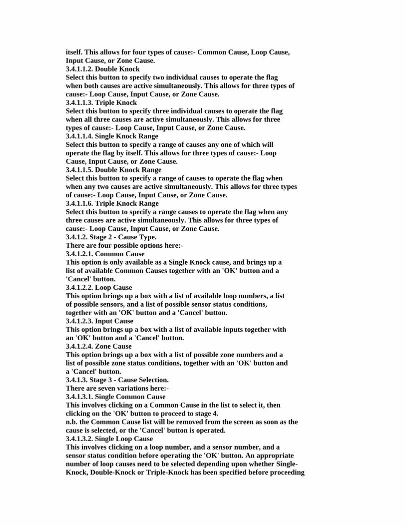
3.4.1. Add New Flag.Creating Unique Causes: WARNING.MAKE SURE YOU ARE FULLY CAPABLE AND UNDERSTAND CAUSE AND EFFECT. RECORD STATE OF CAUSES > AND RECORD NEW CAUSES CREATED, SO THAT IT CAN BE DELETED IF PANEL DOES NOT OPERATE OR GIVES A FAULT or A BADLY WRITTEN CAUSE AND EFFECT/MISTAKE) **** TIP: BACK UP FOLDER THEN CREATE CAUSE AND EFFECT*** When this option is selected, a box appears identifying the new flag number, and offering various option buttons plus a 'Cancel' button. Flag specification takes place in four stages, with appropriate options being given at each stage.
3.4.1.1. Stage 1 - Cause number & Combination Options. There are six options on offer here, as well as a 'Cancel' button to return to the menu bar options. 3.4.1.1.1. Single Knock Select this button to specify an individual cause to operate the flag by
itself. This allows for four types of cause:- Common Cause, Loop Cause, Input Cause, or Zone Cause. 3.4.1.1.2. Double Knock Select this button to specify two individual causes to operate the flag when both causes are active simultaneously. This allows for three types of cause:- Loop Cause, Input Cause, or Zone Cause. 3.4.1.1.3. Triple Knock Select this button to specify three individual causes to operate the flag when all three causes are active simultaneously. This allows for three types of cause:- Loop Cause, Input Cause, or Zone Cause. 3.4.1.1.4. Single Knock Range Select this button to specify a range of causes any one of which will operate the flag by itself. This allows for three types of cause:- Loop Cause, Input Cause, or Zone Cause. 3.4.1.1.5. Double Knock Range Select this button to specify a range of causes to operate the flag when when any two causes are active simultaneously. This allows for three types of cause:- Loop Cause, Input Cause, or Zone Cause. 3.4.1.1.6. Triple Knock Range Select this button to specify a range causes to operate the flag when any three causes are active simultaneously. This allows for three types of cause:- Loop Cause, Input Cause, or Zone Cause. 3.4.1.2. Stage 2 - Cause Type. There are four possible options here:- 3.4.1.2.1. Common Cause This option is only available as a Single Knock cause, and brings up a list of available Common Causes together with an 'OK' button and a 'Cancel' button. 3.4.1.2.2. Loop Cause This option brings up a box with a list of available loop numbers, a list of possible sensors, and a list of possible sensor status conditions, together with an 'OK' button and a 'Cancel' button. 3.4.1.2.3. Input Cause This option brings up a box with a list of available inputs together with an 'OK' button and a 'Cancel' button. 3.4.1.2.4. Zone Cause This option brings up a box with a list of possible zone numbers and a list of possible zone status conditions, together with an 'OK' button and a 'Cancel' button. 3.4.1.3. Stage 3 - Cause Selection. There are seven variations here:- 3.4.1.3.1. Single Common Cause This involves clicking on a Common Cause in the list to select it, then clicking on the 'OK' button to proceed to stage 4. n.b. the Common Cause list will be removed from the screen as soon as the cause is selected, or the 'Cancel' button is operated. 3.4.1.3.2. Single Loop Cause This involves clicking on a loop number, and a sensor number, and a sensor status condition before operating the 'OK' button. An appropriate number of loop causes need to be selected depending upon whether Single- Knock, Double-Knock or Triple-Knock has been specified before proceeding

to stage 4. n.b. the loop cause list will remain visible until sufficient causes have been selected, or the 'Cancel' button is operated. 3.4.1.3.3. Single Input Cause This involves clicking on an input number then operating the 'OK' button. An appropriate number of input causes need to be selected depending upon whether Single-Knock, Double-Knock or Triple-Knock has been specified before proceeding to stage 4. n.b. the input cause list will remain visible until sufficient causes have been selected, or the 'Cancel' button is operated. 3.4.1.3.4. Single Zone Cause This involves clicking on a zone number and a zone status condition before operating the 'OK' button. An appropriate number of zone causes need to be selected depending upon whether Single-Knock, Double-Knock or Triple-Knock has been specified before proceeding to stage 4. n.b. the zone cause list will remain visible until sufficient causes have been selected, or the 'Cancel' button is operated. 3.4.1.3.5. Range of Loop Causes This involves clicking on a loop number, and a range of sensor numbers, and a sensor status condition before operating the 'OK' button. The range of sensor numbers is selected by moving the mouse pointer to the first sensor number, pressing the left mouse button and dragging the mouse pointer to the last sensor number before releasing the button. The selected devices will be highlighted. n.b. the loop cause list will be removed from the screen when either a valid cause is selected, or the 'Cancel' button is operated. 3.4.1.3.6. Range of Input Causes This involves selecting a range of input numbers before operating the 'OK' button. The range of input numbers is selected by moving the mouse pointer to the first input number, pressing the left mouse button and dragging the mouse pointer to the last input number before releasing the button. The selected inputs will be highlighted. n.b. the input cause list will be removed from the screen when either a valid cause is selected, or the 'Cancel' button is operated. 3.4.1.3.7. Range of Zone Causes This involves selecting a range of zone numbers, and a zone status condition before operating the 'OK' button. The range of zone numbers is selected by moving the mouse pointer to the first zone number, pressing the left mouse button and dragging the mouse pointer to the last zone number before releasing the button. The selected zones will be highlighted. n.b. the zone cause list will be removed from the screen when either a valid cause is selected, or the 'Cancel' button is operated. 3.4.1.4. Stage 4 - Clearing Mode Selection. The options presented here will depend upon the cause type selected, but as soon as one of these options has been selected then the appropriate cause will be added to the definition for the current flag, and the program will return to stage 1 above, still for the same flag, so that further causes may be specified for that flag. 3.4.1.4.1. On Till Cause Clear This option is available for all cause types, and means that the flag will only be activated while the cause itself is active. 3.4.1.4.2. On Till Silence
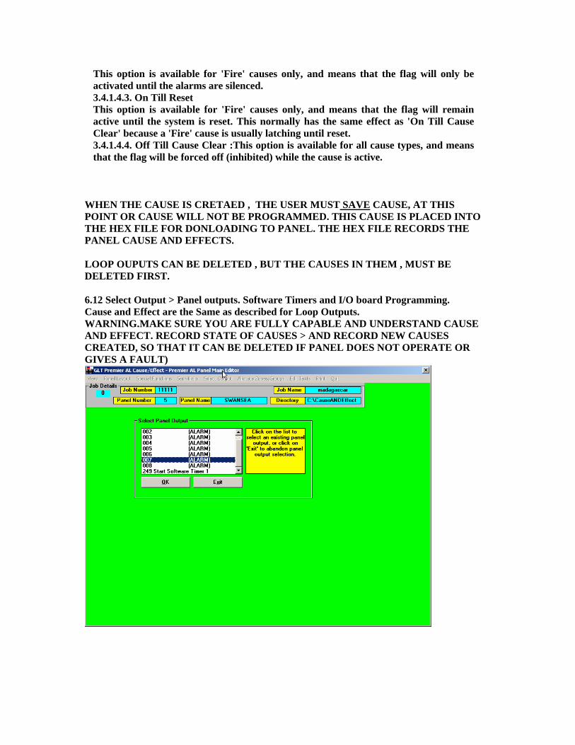
This option is available for 'Fire' causes only, and means that the flag will only be activated until the alarms are silenced. 3.4.1.4.3. On Till Reset This option is available for 'Fire' causes only, and means that the flag will remain active until the system is reset. This normally has the same effect as 'On Till Cause Clear' because a 'Fire' cause is usually latching until reset. 3.4.1.4.4. Off Till Cause Clear :This option is available for all cause types, and means that the flag will be forced off (inhibited) while the cause is active.
WHEN THE CAUSE IS CRETAED , THE USER MUST SAVE CAUSE, AT THIS POINT OR CAUSE WILL NOT BE PROGRAMMED. THIS CAUSE IS PLACED INTO THE HEX FILE FOR DONLOADING TO PANEL. THE HEX FILE RECORDS THE PANEL CAUSE AND EFFECTS. LOOP OUPUTS CAN BE DELETED , BUT THE CAUSES IN THEM , MUST BE DELETED FIRST. 6.12 Select Output > Panel outputs. Software Timers and I/O board Programming. Cause and Effect are the Same as described for Loop Outputs. WARNING.MAKE SURE YOU ARE FULLY CAPABLE AND UNDERSTAND CAUSE AND EFFECT. RECORD STATE OF CAUSES > AND RECORD NEW CAUSES CREATED, SO THAT IT CAN BE DELETED IF PANEL DOES NOT OPERATE OR GIVES A FAULT)

7.11 Allocate Zone/Groups > Allocate > Allocate Zone/Groups to Points. This Section is where the USER , plans a list of which zones and groups the sensor/detectors are to be allocated or placed in. Also Grouping in common or local . There are 32 Zones, which are mutually exclusive. If sensor 1 is in zone 1, it cannot be placed in any other Zone upto zone 32. It can however be placed in any zone/group from 33 to 248.
Premier AL Zone/Group Allocation n.b. Although the word ZONE is generally used in this area, zones 33-255 are reserved for cause/effect operations and are often referred to as groups (including the panel menu pages). Each loop device may be allocated to 1 zone (1-32) and up to 7 groups (33-255). Each panel input may be allocated to up to 8 groups (33-255). Here is Also where to REMOVE sensors from zones and Groups. 7.12 Allocate Zone/Groups > View > This screen offers the following menu options:- Allocate Zone/Groups > View > Zones groups for points This brings up two boxes, one giving a list of available loops and a list of sensor addresses, while the other gives up to the zone number and up to seven group numbers and a 'Cancel' button. Whenever a loop number and a sensor number are selected, the list of zones/groups identifies the currently allocated zones/groups for that sensor. Operating the 'Cancel' button clears these boxes from the screen and reenables the menu options. Allocate Zone/Groups > View > Zones groups for Input

This brings up two boxes, one giving a list of available panel inputs, while the other gives up to eight group numbers and a 'Cancel' button. Allocate Zone/Groups > View > Point/inputs for zone group. User can view what is allocated. (L1:001 = Loop 1 , device address 001 is in zone 1)
8.11 Edit texts > Select Text Category >
Here the user can define Point texts, panel name etc.
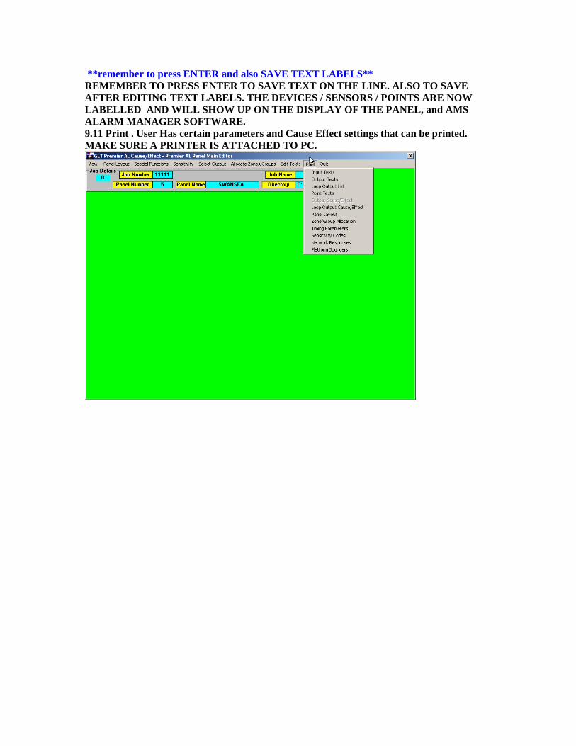
**remember to press ENTER and also SAVE TEXT LABELS** REMEMBER TO PRESS ENTER TO SAVE TEXT ON THE LINE. ALSO TO SAVE AFTER EDITING TEXT LABELS. THE DEVICES / SENSORS / POINTS ARE NOW LABELLED AND WILL SHOW UP ON THE DISPLAY OF THE PANEL, and AMS ALARM MANAGER SOFTWARE. 9.11 Print . User Has certain parameters and Cause Effect settings that can be printed. MAKE SURE A PRINTER IS ATTACHED TO PC.
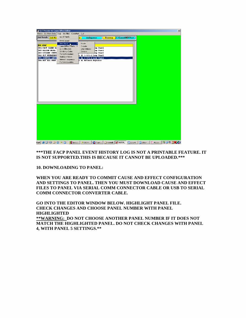
***THE FACP PANEL EVENT HISTORY LOG IS NOT A PRINTABLE FEATURE. IT IS NOT SUPPORTED.THIS IS BECAUSE IT CANNOT BE UPLOADED.*** 10. DOWNLOADING TO PANEL: WHEN YOU ARE READY TO COMMIT CAUSE AND EFFECT CONFIGURATION AND SETTINGS TO PANEL. THEN YOU MUST DOWNLOAD CAUSE AND EFFECT FILES TO PANEL VIA SERIAL COMM CONNECTOR CABLE OR USB TO SERIAL COMM CONNECTOR CONVERTER CABLE. GO INTO THE EDITOR WINDOW BELOW. HIGHLIGHT PANEL FILE. CHECK CHANGES AND CHOOSE PANEL NUMBER WITH PANEL HIGHLIGHTED **WARNING: DO NOT CHOOSE ANOTHER PANEL NUMBER IF IT DOES NOT MATCH THE HIGHLIGHTED PANEL. DO NOT CHECK CHANGES WITH PANEL 4, WITH PANEL 5 SETTINGS.**
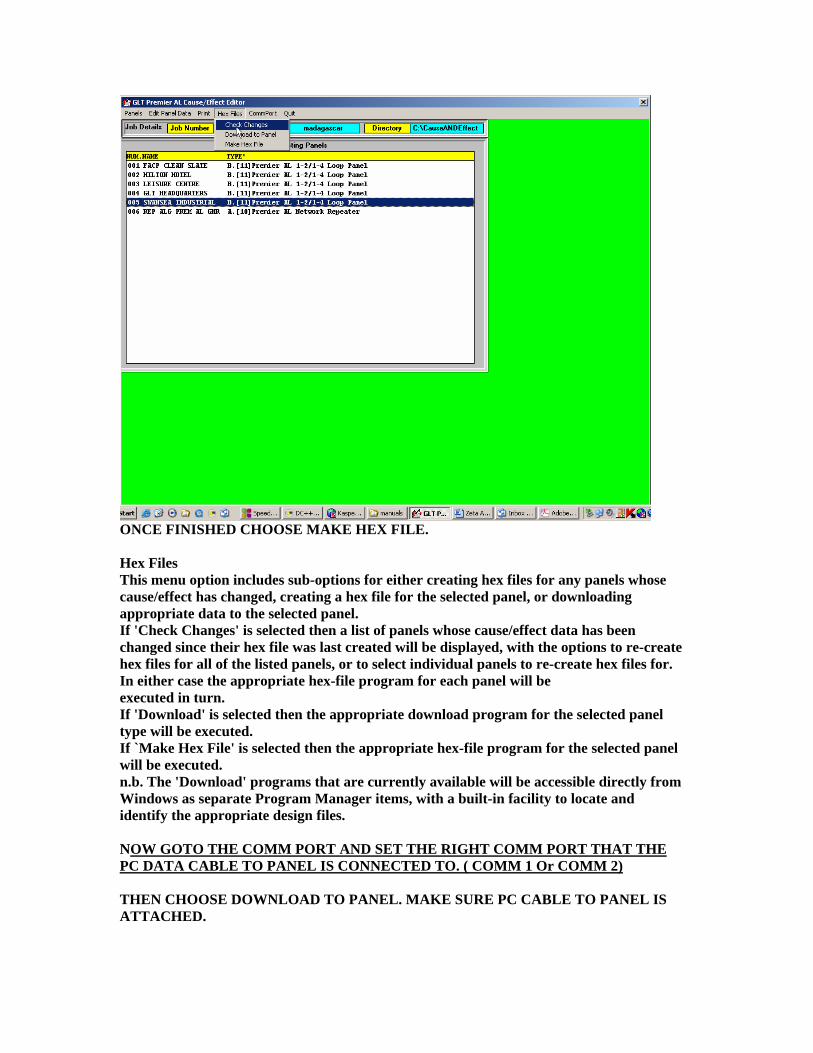
ONCE FINISHED CHOOSE MAKE HEX FILE. Hex Files This menu option includes sub-options for either creating hex files for any panels whose cause/effect has changed, creating a hex file for the selected panel, or downloading appropriate data to the selected panel. If 'Check Changes' is selected then a list of panels whose cause/effect data has been changed since their hex file was last created will be displayed, with the options to re-create hex files for all of the listed panels, or to select individual panels to re-create hex files for. In either case the appropriate hex-file program for each panel will be executed in turn. If 'Download' is selected then the appropriate download program for the selected panel type will be executed. If `Make Hex File' is selected then the appropriate hex-file program for the selected panel will be executed. n.b. The 'Download' programs that are currently available will be accessible directly from Windows as separate Program Manager items, with a built-in facility to locate and identify the appropriate design files. NOW GOTO THE COMM PORT AND SET THE RIGHT COMM PORT THAT THE PC DATA CABLE TO PANEL IS CONNECTED TO. ( COMM 1 Or COMM 2) THEN CHOOSE DOWNLOAD TO PANEL. MAKE SURE PC CABLE TO PANEL IS ATTACHED.

USER WILL BE PROMPTED TO ENTER ACCESS CODE. ( default 8812) Once the panel details have been identified, the program requests the current panel access code to be entered. The program then asks whether or not the panel name or job name is to be used for the company logo on the panel, before checking what information is available for downloading.
The program then tries to identify the panel connected to the serial port of the computer. A red Progress Bar indicates communication.
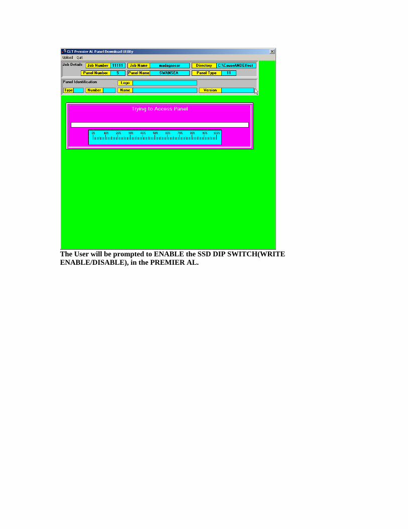
The User will be prompted to ENABLE the SSD DIP SWITCH(WRITE ENABLE/DISABLE), in the PREMIER AL.
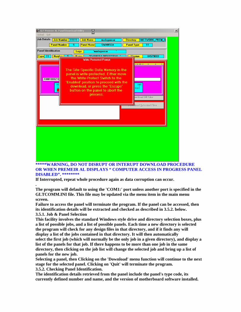
*****WARNING, DO NOT DISRUPT OR INTERUPT DOWNLOAD PROCEDURE OR WHEN PREMEIR AL DISPLAYS “ COMPUTER ACCESS IN PROGRESS PANEL DISABLED”. ******** If Interrupted, repeat whole procedure again as data corruption can occur. . The program will default to using the 'COM1:' port unless another port is specified in the GLTCOMM.INI file. This file may be updated via the menu item in the main menu screen. Failure to access the panel will terminate the program. If the panel can be accessed, then its identification details will be extracted and checked as described in 3.5.2. below. 3.5.1. Job & Panel Selection This facility involves the standard Windows style drive and directory selection boxes, plus a list of possible jobs, and a list of possible panels. Each time a new directory is selected the program will check for any design files in that directory, and if it finds any will display a list of the jobs contained in that directory. It will then automatically select the first job (which will normally be the only job in a given directory), and display a list of the panels for that job. If there happens to be more than one job in the same directory, then clicking on the job list will change the selected job and bring up a list of panels for the new job. Selecting a panel, then Clicking on the 'Download' menu function will continue to the next stage for the selected panel. Clicking on 'Quit' will terminate the program. 3.5.2. Checking Panel Identification. The identification details retrieved from the panel include the panel's type code, its currently defined number and name, and the version of motherboard software installed.

If the type code returned is not 11 which represents the Premier AL panel, then the program will terminate. If the panel number returned is different from that specified on the computer, then a prompt will appear asking whether it is required to change the panel's number or not. If 'No' is selected, and the number returned by the panel is not 0 then the program will terminate, otherwise if the number from the panel is 0 then the panel name will be checked, but if 'Yes' is selected then the panel number specified on the computer will be transferred to the panel, and the program will then proceed to check the panel name. Similarly if the panel name returned is different from that specified on the computer, then an option will be given to update the name stored in the panel to that specified on the computer. This time however selecting 'No' will not terminate the program, but proceed directly to the next stage. n.b. a stand-alone panel will always return a panel number of 0, and this cannot be changed. 3.5.3. Selecting Download Information. When the panel's identification has been successfully checked, a list of suitable data files existing on the computer will be displayed, with the option to download all of the data, or just selected files. Clicking on 'All' will download all of the available information to the panel, while Clicking on 'Selected' will only download any files that are highlighted in the list. n.b. A progress bar will be displayed during each download process for reference. Also if the panel has a switch for write-protecting its EEPROM memory, and that switch is in the 'Protected' position, then a warning prompt will be displayed giving the user an opportunity to move the switch into the 'Enabled' position before proceeding with the download, or to terminate the download process.
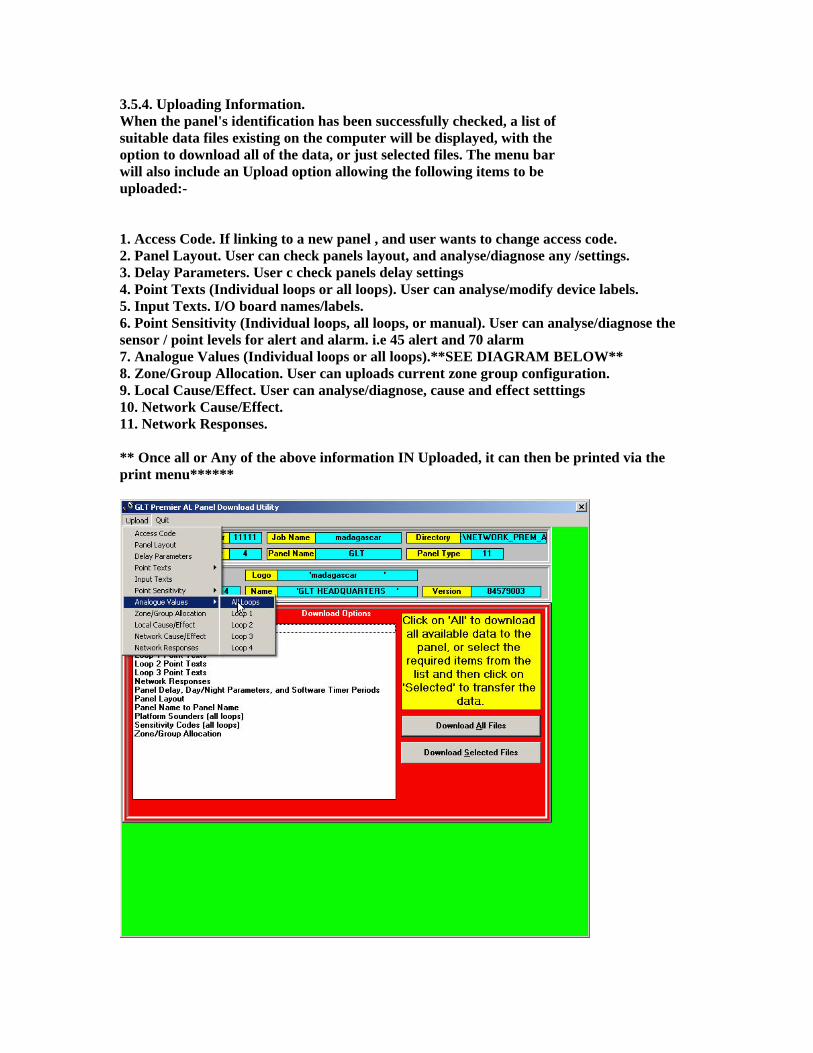
3.5.4. Uploading Information. When the panel's identification has been successfully checked, a list of suitable data files existing on the computer will be displayed, with the option to download all of the data, or just selected files. The menu bar will also include an Upload option allowing the following items to be uploaded:- 1. Access Code. If linking to a new panel , and user wants to change access code. 2. Panel Layout. User can check panels layout, and analyse/diagnose any /settings. 3. Delay Parameters. User c check panels delay settings 4. Point Texts (Individual loops or all loops). User can analyse/modify device labels. 5. Input Texts. I/O board names/labels. 6. Point Sensitivity (Individual loops, all loops, or manual). User can analyse/diagnose the sensor / point levels for alert and alarm. i.e 45 alert and 70 alarm 7. Analogue Values (Individual loops or all loops).**SEE DIAGRAM BELOW** 8. Zone/Group Allocation. User can uploads current zone group configuration. 9. Local Cause/Effect. User can analyse/diagnose, cause and effect setttings 10. Network Cause/Effect. 11. Network Responses. ** Once all or Any of the above information IN Uploaded, it can then be printed via the print menu******
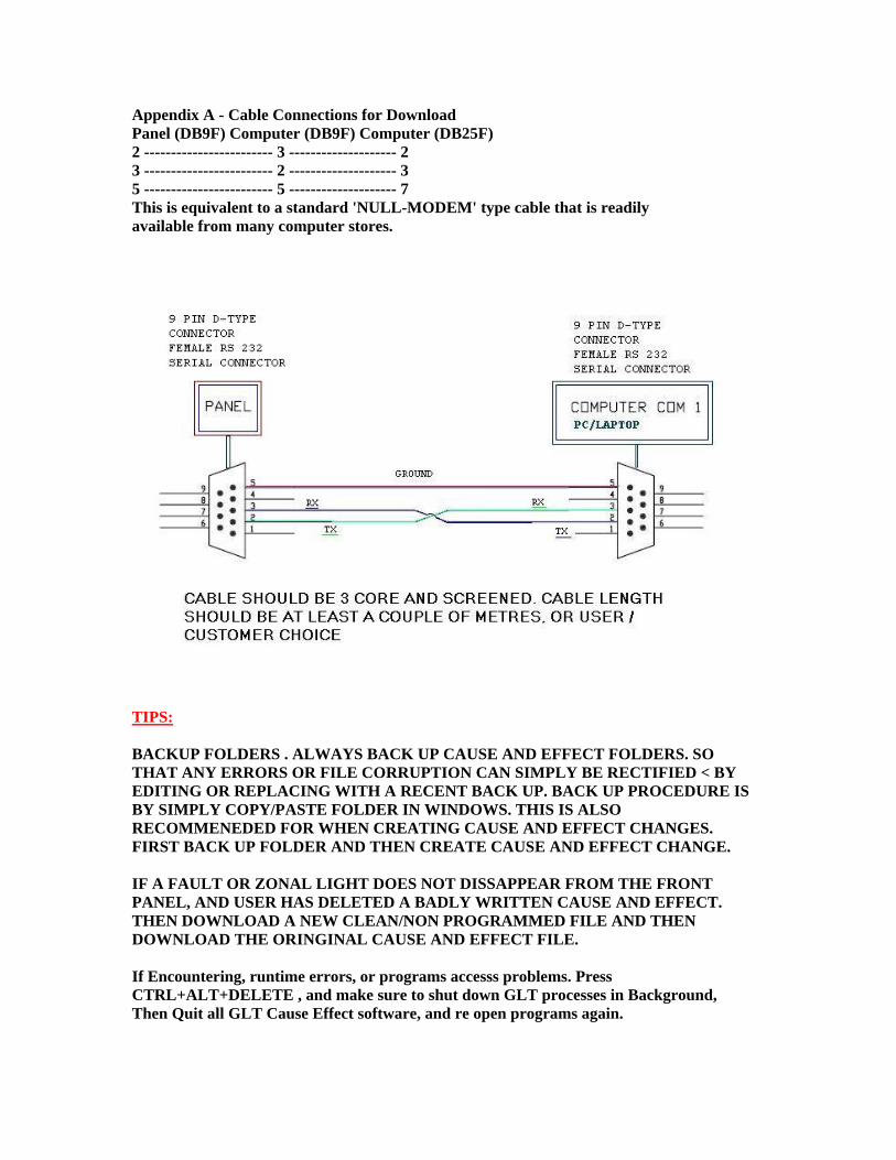
Appendix A - Cable Connections for Download Panel (DB9F) Computer (DB9F) Computer (DB25F) 2 ------------------------ 3 -------------------- 2 3 ------------------------ 2 -------------------- 3 5 ------------------------ 5 -------------------- 7 This is equivalent to a standard 'NULL-MODEM' type cable that is readily available from many computer stores.
TIPS: BACKUP FOLDERS . ALWAYS BACK UP CAUSE AND EFFECT FOLDERS. SO THAT ANY ERRORS OR FILE CORRUPTION CAN SIMPLY BE RECTIFIED < BY EDITING OR REPLACING WITH A RECENT BACK UP. BACK UP PROCEDURE IS BY SIMPLY COPY/PASTE FOLDER IN WINDOWS. THIS IS ALSO RECOMMENEDED FOR WHEN CREATING CAUSE AND EFFECT CHANGES. FIRST BACK UP FOLDER AND THEN CREATE CAUSE AND EFFECT CHANGE. IF A FAULT OR ZONAL LIGHT DOES NOT DISSAPPEAR FROM THE FRONT PANEL, AND USER HAS DELETED A BADLY WRITTEN CAUSE AND EFFECT. THEN DOWNLOAD A NEW CLEAN/NON PROGRAMMED FILE AND THEN DOWNLOAD THE ORINGINAL CAUSE AND EFFECT FILE. If Encountering, runtime errors, or programs accesss problems. Press CTRL+ALT+DELETE , and make sure to shut down GLT processes in Background, Then Quit all GLT Cause Effect software, and re open programs again.