Embed Size (px)
Citation preview
3 Thermal Design Examples
D. G. Gilmore,* Y. Yoshikawa, t R. Stoll, ~ R. Bettini, ~ B. Patti,** G. Cluzet, t t J. Doenecke, ;~ K. Vollmer, ; ; C. Finch,*** and B. Turner***
Introduction The purpose of a thermal-control system is to maintain all of a spacecraft's com- ponents within the allowable temperature limits for all operating modes of the vehicle, in all of the thermal environments it may be exposed to (i.e., those dis- cussed in Chapter 2). To illustrate how thermal control is achieved, this chapter describes some typical thermal designs. While these designs are currently in wide use, they are not the only possible thermal designs for the spacecraft and compo- nents examined here, and creative alternative solutions to thermal design problems are always desirable. The designs described in the following discussions should therefore be considered examples only.
Establishing a thermal design for a spacecraft is usually a two-part process. The first step is to select a thermal design for the body, or basic enclosures, of the spacecraft that will serve as a thermal sink for all internal components. The second step is to select thermal designs for various components located both within and outside the spacecraft body. The following sections give a qualitative description of typical designs. For a more detailed discussion of the design-selection process and the thermal analysis required to verify a design, see Chapter 15, "Thermal Design Analysis."
Spin-Stabilized Satellites Of all the thermal designs for spin-stabilized satellites ("spinners"), the most com- mon is the one typified by Defense Satellite Communications System (DSCS) II, Satellite Data Systems, North Atlantic Treaty Organization (NATO) II, and a host of commercial communication satellites. The design approach is to use the spin- ning solar array as a heat sink for the internal components. A cylinder spinning with the sun normal to the spin axis will be close to room temperature if the ratio of solar absorption to infrared (IR) emittance (~e) is near 1.0, as is the approxi- mate case with the solar cells that cover the cylinder. Because of its temperature, the spinning solar array makes a convenient heat sink for internal components.
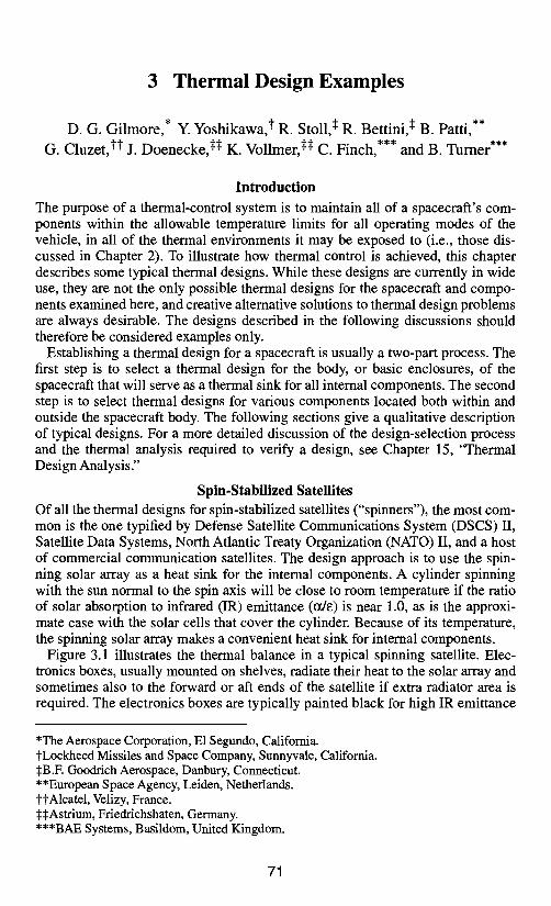
Figure 3.1 illustrates the thermal balance in a typical spinning satellite. Elec- tronics boxes, usually mounted on shelves, radiate their heat to the solar array and sometimes also to the forward or aft ends of the satellite if extra radiator area is required. The electronics boxes are typically painted black for high IR emittance
*The Aerospace Corporation, E1 Segundo, California. tLockheed Missiles and Space Company, Sunnyvale, California. ~B.F. Goodrich Aerospace, Danbury, Connecticut. **European Space Agency, Leiden, Netherlands. ttAlcatel, Velizy, France. ~:~Astrium, Friedrichshaten, Germany. ***BAE Systems, Basildom, United Kingdom.
71
72 Thermal Design Examples
ummer sun " ~
Fig. 3.1. "Spinner" thermal balance.
and are mounted so as to ensure good heat conduction to the shelves. For most boxes the combined surface area of the box itself and its shelf is sufficient to radi- ate the waste heat to the solar array without development of a large temperature difference between the box and the room-temperature array. If a box is small and has high heat dissipation, a thermal "doubler" (a sheet of high-conductivity mate- rial such as aluminum, beryllium, or copper) may be placed under the box to help spread the heat out on the shelf and increase the effective radiating area of the box.
Because most spinners are placed in high-altitude geosynchronous orbits, they experience no more than one eclipse per day, and those eclipses last a maximum of 72 min. During eclipse the solar-array temperature drops dramatically, typi- cally from room temperature to a value on the order of-75°C. In this period, the temperature of the electronics boxes and other components also drops; however, because their thermal mass is high, they do not cool nearly as fast as the relatively lightweight solar array. The result is that the spacecraft can often coast through the eclipse without falling below the minimum allowable operating temperature of the electronics. If the thermal design analysis shows that some components get too cold, then either a lower-emittance finish on the cold units or a heater may be required to reduce their radiative coupling to the solar array or provide extra heat during eclipse. The use of heaters during eclipse should be minimized, however, since they drive up the size, and therefore the mass, of batteries.
Three-Axis-Stabilized Satellites
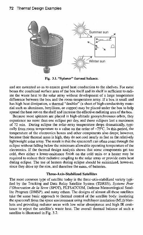
The most common type of satellite today is the three-axis-stabilized variety typi- fied by the Tracking and Data Relay Satellite System (TDRSS), Systeme Pour l'Observation de la Terre (SPOT), FLTSATCOM, Defense Meteorological Satel- lite Program (DMSP), and many others. The designs of almost all these satellites take the same basic approach to thermal control of the satellite body: insulating the spacecraft from the space environment using multilayer insulation (MLI) blan- kets and providing radiator areas with low solar absorptance and high IR emit- tance to reject the satellite's waste heat. The overall thermal balance of such a satellite is illustrated in Fig. 3.2.
Propulsion Systems 73
• Insulate main body with multilayer insulation (MLI) blanket
• Provide low solar absorptance (o~), high infrared emittance (~) radiators to reject waste heat
• Use heaters to protect equipment when satellite is in low power mode MLI
• Use surface finishes and insulation to control appendage temperatures (antennas and Heater\ solar arrays typically have very wide temperature ranges) Electronics
waste heat
Fig. 3.2. Three-axis-satellite thermal control.
Environmental heating
Radiator
The high-power-dissipation boxes in a three-axis satellite are usually mounted on the walls of the satellite; this positioning provides them with a direct conduc- tion path to the radiating areas on the outside surface. As with the spinner, some of the high-power boxes in the three-axis satellite may require a doubler or heat pipes to spread the heat out over a wider area of the wall to which they are mounted. Boxes mounted on shelves, panels, and other structures internal to the vehicle radiate their waste heat directly or indirectly to the outside walls of the spacecraft, where the heat is then rejected to space. Because this type of design is insulated and uses low-solar-absorptance radiators, it is less sensitive to sun position, albedo loads, and eclipses than designs for spinners are.
Propulsion Systems
Almost all satellites have onboard propulsion systems for attitude control and small orbit corrections. The propulsion system typically consists of small (less than 3 kg of thrust) compressed-gas or liquid-propellant thrusters and all the assorted tanks, lines, valves, and other components used to store propellants and feed the thrusters. Some satellites may also have a solid-rocket motor to provide the final boost from transfer orbit to operational orbit. Propulsion-system compo- nents must meet special thermal-control requirements to avoid the freezing of liq- uid propellants, to prevent temperature gradients within solid propellants, and to limit the temperature differences between fuel and oxidizer in liquid bipropellant systems.
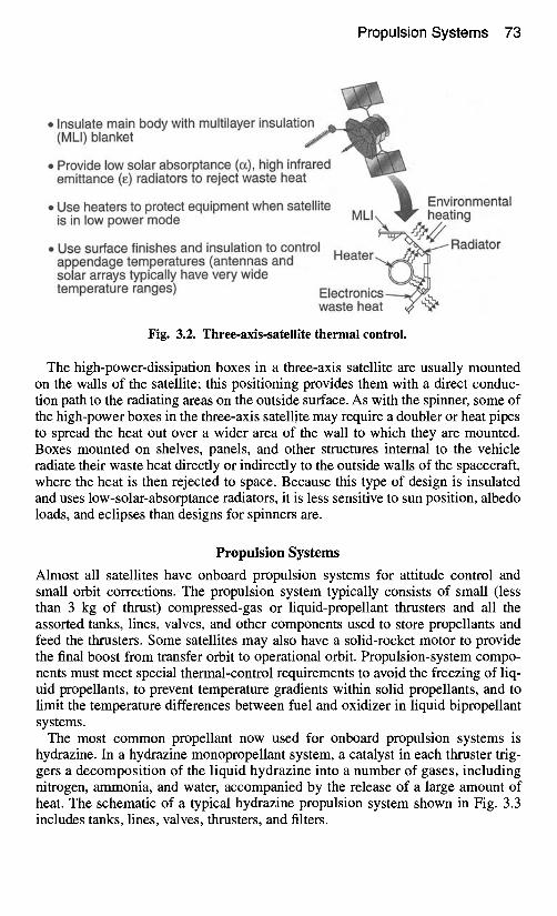
The most common propellant now used for onboard propulsion systems is hydrazine. In a hydrazine monopropellant system, a catalyst in each thruster trig- gers a decomposition of the liquid hydrazine into a number of gases, including nitrogen, ammonia, and water, accompanied by the release of a large amount of heat. The schematic of a typical hydrazine propulsion system shown in Fig. 3.3 includes tanks, lines, valves, thrusters, and filters.
74 Thermal Design Examples
Tank 1 Tank 2 Tank 3 FVl F D 1 % ~ . _ % ( ~ -" - ~ F D 2 ] F D 3~T~'~
R= Roll .-. I LVl I P = Pitch (PI~-I
c~hedYbd~a ~t a t ~ s l ~LV3 ! on all thrusters I
Tank 4 ~ FV4 Fill & vent valve (4)
N2H 4 ) ~._"~FD4 ~-- {~Fi l l & drain valve (4) ~ Filter (4)
-l'~'~Titanium to ' I _ stainless-steel joint
I-(~ Pressure ~,.c., transducer (4)
{NLatl kv6ching valve (6)
(+X)(-X) -R +R-P +P -Y +Y-R +R -P +P -Y +Y (+XI(-X)
North East AV West AV West AV East AV South AV
Fig. 3.3. DSCS propulsion-system schematic.
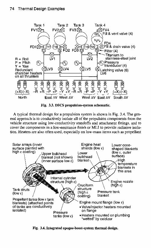
A typical thermal design for a propulsion system is shown in Fig. 3.4. The gen- eral approach is to conductively isolate all of the propulsion components from the vehicle structure using low-conductivity standoffs and attachment fittings, and to cover the components in a low-emittance finish or MLI to provide radiative isola- tion. Heaters are also often used, especially on low-mass items such as propellant
Solar arrays (inner surface painted with high ~ coating) / Upper bulkhead
/ blanket (not shown) ~ / ( inner surface low ~)
Engine heat shields (low ~)
Lower bulkhead blanket \ _..
Lower cone- shaped blankets (low ~, outer surface)
~ High temperature blankets in this area
Internal cylinder structure (high ~)
Tank struts (low ~) Propellant tanks (low ~ tank blankets) (attached points of tanks are conductively isolated) Pressure
tanks (low ~)
" Engine nozzle / Cruciform \ (high ~)
/ ~ / structure \ / ' ~ ~ ' % (high ~ Pressure tank ~ coating) blanket
?Er~,/ " Engine mount flange (low E) / • Valve/injector heaters mounted
on flange • Heaters mounted on plumbing
'SNetted" by oxidizer
Fig. 3.4. Integrated apogee-boost-system thermal design.
Propulsion Systems 75
lines, which may cool very quickly during eclipses or other short-term cold condi- tions. Heaters may be either hardwired (on all the time) or controlled to a fixed temperature using thermostats or solid-state controllers. In addition, the heater power density (W/cm of line) may sometimes have to be varied along the line to ensure that acceptable temperatures are maintained as the line runs through "hot" and "cold" areas of the spacecraft. Heaters must be used and propulsion compo- nents must be isolated, because the spacecraft may get quite cold during some launch or operational modes, and hydrazine freezes at 2°C.
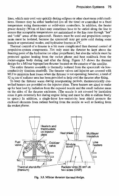
Thermal control of a thruster is a bit more complicated than thermal control of propulsion-system components. Not only must the thruster be kept above the freezing point of the hydrazine (or other propellants), but also the vehicle must be protected against heating from the rocket plume and heat soakback from the rocket-engine body during and after the firing. Figure 3.5 shows the thermal design for a Milstar bipropellant thruster located on the exterior of the satellite.
The entire thruster assembly is thermally isolated from the spacecraft via low- conductivity titanium standoffs. The thruster valves and injector are covered with MLI to minimize heat losses when the thruster is not operating; however, a total of 52 sq cm of radiator area has been provided to help cool the thruster after firing.
To keep the thruster warm during nonoperating periods, thermostatically con- trolled heaters are provided on the injector plate. These heaters are sized to make up for heat lost by radiation from the exposed nozzle and the small radiator areas on the sides of the thruster enclosure. (The nozzle is not covered by insulation since it gets extremely hot during engine firing and must be able to radiate freely to space.) In addition, a single-layer low-emissivity heat shield protects the enclosed elements from radiant heating from the nozzle as well as heating from the rocket plume.
/Heaters and ~ [ ~ thermostats ')1( on!njector Heatshield ~ Multilayer
prate \ I I insulation --..._ i - - l - - - I ~ - ~ , ' / / Fuel y3a_~.<., ,-~,, .~-~ .. Oxidize r . ~ / Line
va,ve llll va,ve heaters
I ~ "~-~) - - / I
The! Imal standoffs ~ l ~ IA-'D-!;;-2; "c -Im2~;; ---i (titanium) two sides (OSR)
Fig. 3.5. Milstar thruster thermal design.
76 Thermal Design Examples
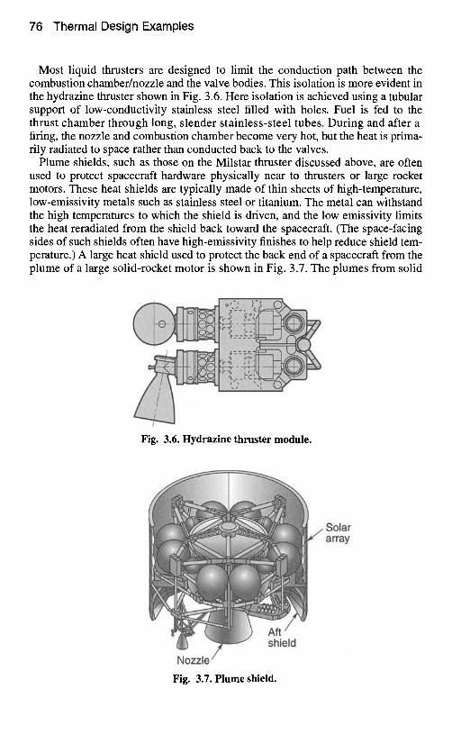
Most liquid thrusters are designed to limit the conduction path between the combustion chamber/nozzle and the valve bodies. This isolation is more evident in the hydrazine thruster shown in Fig. 3.6. Here isolation is achieved using a tubular support of low-conductivity stainless steel filled with holes. Fuel is fed to the thrust chamber through long, slender stainless-steel tubes. During and after a firing, the nozzle and combustion chamber become very hot, but the heat is prima- rily radiated to space rather than conducted back to the valves.
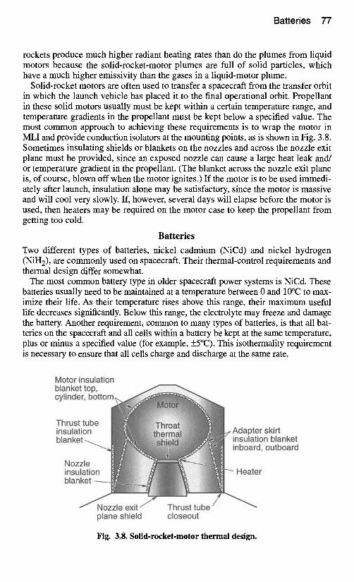
Plume shields, such as those on the Milstar thruster discussed above, are often used to protect spacecraft hardware physically near to thrusters or large rocket motors. These heat shields are typically made of thin sheets of high-temperature, low-emissivity metals such as stainless steel or titanium. The metal can withstand the high temperatures to which the shield is driven, and the low emissivity limits the heat reradiated from the shield back toward the spacecraft. (The space-facing sides of such shields often have high-emissivity finishes to help reduce shield tem- perature.) A large heat shield used to protect the back end of a spacecraft from the plume of a large solid-rocket motor is shown in Fig. 3.7. The plumes from solid
Fig. 3.6. Hydrazine thruster module.
Solar array
Fig. 3.7. Plume shield.
Batteries 77
rockets produce much higher radiant heating rates than do the plumes from liquid motors because the solid-rocket-motor plumes are full of solid particles, which have a much higher emissivity than the gases in a liquid-motor plume.
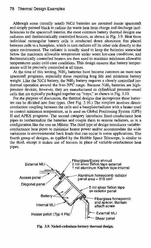
Solid-rocket motors are often used to transfer a spacecraft from the transfer orbit in which the launch vehicle has placed it to the final operational orbit. Propellant in these solid motors usually must be kept within a certain temperature range, and temperature gradients in the propellant must be kept below a specified value. The most common approach to achieving these requirements is to wrap the motor in MLI and provide conduction isolators at the mounting points, as is shown in Fig. 3.8. Sometimes insulating shields or blankets on the nozzles and across the nozzle exit plane must be provided, since an exposed nozzle can cause a large heat leak and/ or temperature gradient in the propellant. (The blanket across the nozzle exit plane is, of course, blown off when the motor ignites.) If the motor is to be used immedi- ately after launch, insulation alone may be satisfactory, since the motor is massive and will cool very slowly. If, however, several days will elapse before the motor is used, then heaters may be required on the motor case to keep the propellant from getting too cold.
Batteries
Two different types of batteries, nickel cadmium (NiCd) and nickel hydrogen (NiH2), are commonly used on spacecraft. Their thermal-control requirements and thermal design differ somewhat.
The most common battery type in older spacecraft power systems is NiCd. These batteries usually need to be maintained at a temperature between 0 and 10°C to max- imize their life. As their temperature rises above this range, their maximum useful life decreases significantly. Below this range, the electrolyte may freeze and damage the battery. Another requirement, common to many types of batteries, is that all bat- teries on the spacecraft and all cells within a battery be kept at the same temperature, plus or minus a specified value (for example, +5°C). This isothermality requirement is necessary to ensure that all cells charge and discharge at the same rate.
Motor insulation blanket top, cylinder, b o t t o ~
Thrust tube ~ ~ ~ insulation ~ ~ ~ blanket ~ ~ ~
Nozzle l~il[~~i ~ insulation l i blankei I
/ ~Nozzle exit ~ plane shield
, n sa, a',er nS ,r'a. inboard, outboard
B Heater
Thrust tube' closeout
Fig. 3.8. Solid-rocket-motor thermal design.
78 Thermal Design Examples
Although some (usually small) NiCd batteries are mounted inside spacecraft and simply painted black to radiate the waste heat from charge and discharge inef- ficiencies to the spacecraft interior, the most common battery thermal designs use radiators and thermostatically controlled heaters, as shown in Fig. 3.9. Heat from individual rectangular battery cells is conducted down aluminum fins placed between cells to a baseplate, which in turn radiates off its other side directly to the space environment. The radiator is usually-sized to keep the batteries somewhat below the maximum allowable temperature under worst hot-case conditions, and thermostatically controlled heaters are then used to maintain minimum allowable temperatures under cold-case conditions. This design ensures that battery temper- atures will be precisely controlled at all times.
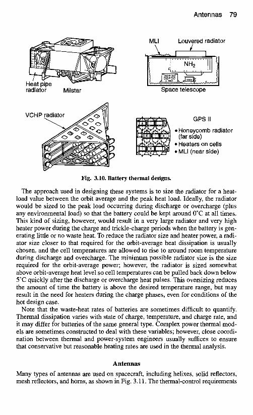
At the time of this writing, NiH 2 batteries have become common on most new spacecraft programs, especially those requiring long life and minimum battery weight. Like the NiCd battery, the NiH 2 battery requires a closely controlled iso- thermal operation around the 0-to-20°C range. Because NiH 2 batteries are high- pressure devices, however, they are manufactured as cylindrical pressure-vessel ceils that are typically packaged together on "trays," as shown in Fig. 3.10.
For the purpose of discussion, the thermal designs that incorporate these batter- ies can be divided into four types. (See Fig. 3.10.) The simplest involves direct- conduction coupling between the cells and a baseplate/radiator with a heater used to control minimum temperature, as is used on Global Positioning System (GPS) II and APEX programs. The second category introduces fixed-conductance heat pipes to isothermalize the batteries and couple them to remote radiators, as in a configuration like the one on Milstar. The third type of design introduces variable- conductance heat pipes to minimize heater power and/or accommodate the wide variations in environmental back loads that can occur in some applications. The fourth group of designs, as typified by the Hubble Space Telescope, is similar to the third, except it makes use of louvers in place of variable-conductance heat pipes.
Fiberglass/Epoxy shroud External MLI 2 mil silver Teflon tape external
1 mil aluminum Kapton tape internal
Aluminum honeycomb radiator Access panel panel area = 516 cm 2
Diagonal panel t ~ 5 mil silver Teflon tape on radiator panel
B~ Fiberglass honeycomb
~ttery Shear panel
and spacer, titanium Internal MLI attach screw
Heater patch (Typ 4 PIs', External MLI
Fig. 3.9. Nickel-cadmium-battery thermal design.
A n t e n n a s 79
Heat pipe radiator Milstar
VCHP
r
MLI Louvered radiator
Space telescope
..~t-,-e_ 1-,-,- ,'_ _-,~. GPS II
. . . . • Honeycomb radiator (far side)
• Heaters on cells ~ :z~z~ ' . z : t • MLI (near side)
t ~ l r w
Fig. 3.10. Battery thermal designs.
The approach used in designing these systems is to size the radiator for a heat- load value between the orbit average and the peak heat load. Ideally, the radiator would be sized to the peak load occurring during discharge or overcharge (plus any environmental load) so that the battery could be kept around 0°C at all times. This kind of sizing, however, would result in a very large radiator and very high heater power during the charge and trickle-charge periods when the battery is gen- erating little or no waste heat. To reduce the radiator size and heater power, a radi- ator size closer to that required for the orbit-average heat dissipation is usually chosen, and the cell temperatures are allowed to rise to around room temperature during discharge and overcharge. The minimum possible radiator size is the size required for the orbit-average power; however, the radiator is sized somewhat above orbit-average heat level so cell temperatures can be pulled back down below 5°C quickly after the discharge or overcharge heat pulses. This oversizing reduces the amount of time the battery is above the desired temperature range, but may result in the need for heaters during the charge phases, even for conditions of the hot design case.
Note that the waste-heat rates of batteries are sometimes difficult to quantify. Thermal dissipation varies with state of charge, temperature, and charge rate, and it may differ for batteries of the same general type. Complex power thermal mod- els are sometimes constructed to deal with these variables; however, close coordi- nation between thermal and power-system engineers usually suffices to ensure that conservative but reasonable heating rates are used in the thermal analysis.
Antennas
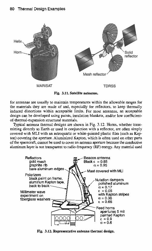
Many types of antennas are used on spacecraft, including helixes, solid reflectors, mesh reflectors, and horns, as shown in Fig. 3.11. The thermal-control requirements
80 Thermal Design Examples
Helix
Horn
MARISAT TDRSS
Fig. 3.11. Satellite antennas.
for antennas are usually to maintain temperatures within the allowable ranges for the materials they are made of and, especially for reflectors, to keep thermally induced distortions within acceptable limits. For most antennas, an acceptable design can be developed using paints, insulation blankets, and/or low coefficient- of-thermal-expansion structural materials.
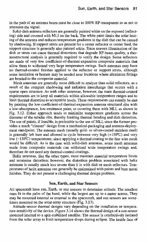
Typical antenna thermal designs are shown in Fig. 3.12. Horns, whether trans- mitting directly to Earth or used in conjunction with a reflector, are often simply covered with MLI with an astroquartz or white-painted plastic film (such as Kap- ton) coveting the aperture. Aluminized Kapton, which is often used on other parts of the spacecraft, cannot be used to cover an antenna aperture because the conductive aluminum layer is not transparent to radio-frequency (RF) energy. Any material used
Reflectors gold mesh graphite rib bare aluminu
Polarizers black paint o~ aluminum Kal back to back
Millimeter wave experiment on fiberglass washers
. . . . . i antenna = 0.85
'= 0.95
covered with MLI
Nutation dampers polished aluminum o~= 0.17
=0.05 with Kapton stripes o~ = 0.36
=0.66
Feed horns apertures 5 mil painted Kapton
=0.9 (z = 0.6
Fig. 3.12. Representative antenna thermal design.
Sun, Earth, and Star Sensors 81
in the path of an antenna beam must be close to 100% RF-transparent so as not to attenuate the signal.
Solid-dish antenna reflectors are generally painted white on the exposed (reflect- ing) side and covered with MLI on the back. The white paint limits the solar heat- ing of the antenna and reduces temperature gradients in the dish that can be caused by shadowing. If support struts are present for a center reflector or center feed, the support structure is generally also painted white. Since uneven illumination of the dish or struts can cause thermal distortions that degrade RF-beam quality, a ther- mostructural analysis is generally required to verify the design. Some reflectors are made of very low coefficient-of-thermal-expansion composite materials that allow them to withstand very large temperature swings. Such antennas may have no thermal-control finishes applied to the reflector or support struts, although some insulation or heaters may be needed near locations where aluminum fittings are bonded to the composite material.
Mesh antennas are generally more difficult to analyze than solid reflectors, as a result of the complex shadowing and radiation interchange that occurs with a sparse open structure. As with other antennas, however, the main thermal-control requirements are to keep all materials within allowable temperature ranges and to limit thermal distortion to acceptable levels. These requirements can usually be met by painting the low-coefficient-of-thermal-expansion antenna structural ribs with a low-absorptance, low-emittance paint, or coveting them with MLI, as shown in Fig. 3.12. Either approach tends to minimize temperature gradients across the diameter of the tubular fibs, thereby limiting thermal bending and dish distortion. The use of paints, if feasible, is preferable to the use of MLI, since the former pro- vides a much "cleaner" design from a mechanical-packaging and antenna-deploy- ment standpoint. The antenna mesh (usually gold- or silver-coated stainless steel) is generally left bare and allowed to cycle between very high (+150°C) and very low (-130°C) temperatures, since applying a thermal coating to the fine wire mesh would be difficult. As is the case with solid-dish antennas, some mesh antennas made from composite materials can withstand wide temperature swings and, therefore do not need any thermal-control coatings.
Helix antennas, like the other types, must maintain material temperature limits and minimize distortion; however, the distortion problem associated with helix antennas is usually much less severe than it is with dish or mesh reflectors. Tem- peratures of helix antennas can generally be maintained with paints and bare metal finishes. They do not present a challenging thermal design problem.
Sun, Earth, and Star Sensors
All spacecraft have sun, Earth, or star sensors to determine attitude. The smallest ones fit in the palm of the hand, while the largest are up to a meter across. They may be mounted internal or external to the spacecraft, and sun sensors are some- times mounted on the solar-array structure (Fig. 3.13).
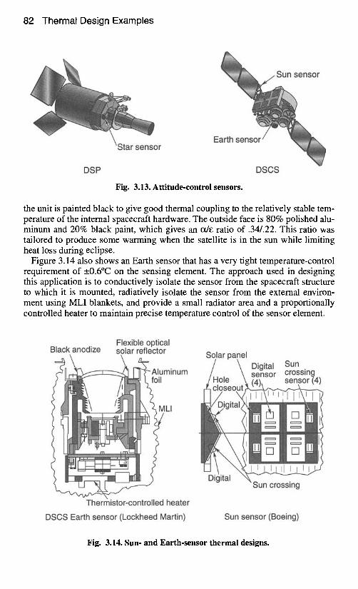
Attitude-sensor thermal designs vary depending on the installation or tempera- ture sensitivity of the device. Figure 3.14 shows the thermal design of a sun sensor mounted internal to a spin-stabilized satellite. The sensor is conductively isolated from the solar array to limit temperature drops during eclipse. The inside face of
82 Thermal Design Examples
4[ r
Earth sensor
Sun sensor
DSP DSCS
Fig. 3.13. Attitude-control sensors.
the unit is painted black to give good thermal coupling to the relatively stable tem- perature of the internal spacecraft hardware. The outside face is 80% polished alu- minum and 20% black paint, which gives an ~/E ratio of .34/.22. This ratio was tailored to produce some warming when the satellite is in the sun while limiting heat loss during eclipse.
Figure 3.14 also shows an Earth sensor that has a very tight temperature-control requirement of _0.6°C on the sensing element. The approach used in designing this application is to conductively isolate the sensor from the spacecraft structure to which it is mounted, radiatively isolate the sensor from the external environ- ment using MLI blankets, and provide a small radiator area and a proportionally controlled heater to maintain precise temperature control of the sensor element.
Flexible optical Black anodize solar reflector
minum
ILl
~un crossing
Thermistor-controlled heater
DSCS Earth sensor (Lockheed Martin) Sun sensor (Boeing)
Fig. 3.14. Sun- and Earth-sensor thermal designs.
Sun, Earth, and Star Sensors 83
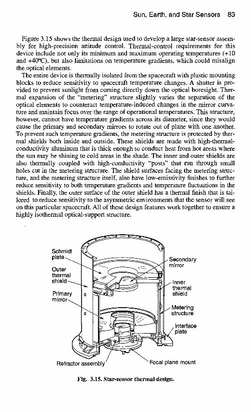
Figure 3.15 shows the thermal design used to develop a large star-sensor assem- bly for high-precision attitude control. Thermal-control requirements for this device include not only its minimum and maximum operating temperatures (+ 10 and +40°C), but also limitations on temperature gradients, which could misalign the optical elements.
The entire device is thermally isolated from the spacecraft with plastic mounting blocks to reduce sensitivity to spacecraft temperature changes. A shutter is pro- vided to prevent sunlight from coming directly down the optical boresight. Ther- mal expansion of the "metering" structure slightly varies the separation of the optical elements to counteract temperature-induced changes in the mirror curva- ture and maintain focus over the range of operational temperatures. This structure, however, cannot have temperature gradients across its diameter, since they would cause the primary and secondary mirrors to rotate out of plane with one another. To prevent such temperature gradients, the metering structure is protected by ther- mal shields both inside and outside. These shields are made with high-thermal- conductivity aluminum that is thick enough to conduct heat from hot areas where the sun may be shining to cold areas in the shade. The inner and outer shields are also thermally coupled with high-conductivity "posts" that run through small holes cut in the metering structure. The shield surfaces facing the metering struc- ture, and the metering structure itself, also have low-emissivity finishes to further reduce sensitivity to both temperature gradients and temperature fluctuations in the shields. Finally, the outer surface of the outer shield has a thermal finish that is tai- lored to reduce sensitivity to the asymmetric environments that the sensor will see on this particular spacecraft. All of these design features work together to ensure a highly isothermal optical-support structure.
Schmidt p l a t e . . . , . . ~ ~ ~ ; ~ ~ ~ ~ ~ ~ ~
Outer I "ilk,.. - / " f ~'-x~---.,,-~x~ '~ thermal I IL ~ ~ 7 " - - ~ - - - 1 ~ sh'e'°"4- P~imary Io II
Refractor assembly
/ Secondary mirror
j Inner thermal shield
j Metering structure
. Interface ~ plate
Focal plane mount
Fig. 3.15. Star-sensor thermal design.
84 Thermal Design Examples
Cooled Devices Some spacecraft payloads require cooling to low temperatures. The most common types of cooled instruments include IR-sensor focal planes and optics, as well as low-noise amplifiers for RF receivers. Several devices are available for cooling such applications, including radiators, stored-cryogen cooling systems, and refrig- erators. This section describes specific designs that make use of coolers; for a more complete discussion of these technologies, see Vol. 2 of this handbook.
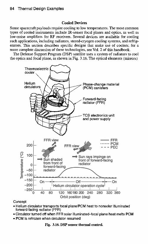
The Defense Support Program (DSP) satellite uses a system of radiators to cool the optics and focal plane, as shown in Fig. 3.16. The optical elements (mirrors)
Thermoelectric cooler.
Helium ~ Phase-change material circulators / (PCM) canisters
Forward-facing radiator (FFR)
TCS electronics unit and power supply
200
¢Jo 100 v
*" 0
(~ -50
FFR view
""~ Sun shaded
FFR . . . . . . P O M
FFR - - - PEC
Sun rays impinge on front of forward-facing
from front of radiator - forward-facing - - r a d i a t o r _ _ / - _ _
E -100 -- , " ~ ~ ~ r . r . r . r . r . r . r . r . r . r ~ ~ r . r ~
-150- - On -iHeliu m Off = -200 circlulato r operal,o n c~cle r -250 [ I I I
0 40 80 120 160180 200 240 280 320 360 Orbit position (deg)
Concept • Helium circulator transports focal plane/PCM heat to nonsolar illuminated
forward-facing radiator (FFR) • Circulator turned off when FFR solar illuminated-focal plane heat melts PCM • PCM is refrozen when circulator resumed
Fig. 3.16. DSP sensor thermal control.
Cooled Devices 85
and the telescope enclosure and baffles are cooled passively by covering the tele- scope enclosure with low-absorptance, high-emittance quartz mirrors. Cooling the optics and enclosure reduces the amount of IR radiation emitted from those sur- faces. Without this cooling, the sensors at the focal plane would not be able to see their targets over the IR "noise" created by the telescope itself. The focal-plane assembly is connected to a phase-change-material (PCM) heat sink and a passive radiator by a pumped-helium loop. The operating principle of this system (shown in Fig. 3.16) is the transporting of heat from the focal plane and PCM to the radia- tor by means of a pumped-helium loop during the half of the orbit when the sun does not shine on the radiator. During the other half-orbit, solar illumination heats the radiator to temperatures well above those of the focal plane. To avoid a focal- plane temperature rise, the helium circulation is shut off, effectively decoupling the radiators, and the heat loads from the focal plane are stored in the PCM. When the sun moves behind the vehicle, the circulator is turned back on to reject the focal-plane heat and the excess heat stored in the PCM. Minimizing heat leaks into the forward-facing radiator by the use of MLI and low-conductance supports on the back side is critical to achieving low-temperature performance. Even small heat leaks into the radiator during the shadowed half-orbit can raise its tempera- ture considerably from 173 K. (Because of the T 4 nature of radiation-heat transfer, only one-fifth as much heat is needed to raise radiator equilibrium temperatures one degree at 173 K than at room temperature. For lower-temperature radiators the sensitivity is even greater; for example, the sensitivity is greater by a factor of 50 at 80 K than at room temperature. For this reason, low-temperature radiators are extremely sensitive to heat loads from the environment or heat leaks from the spacecraft.)
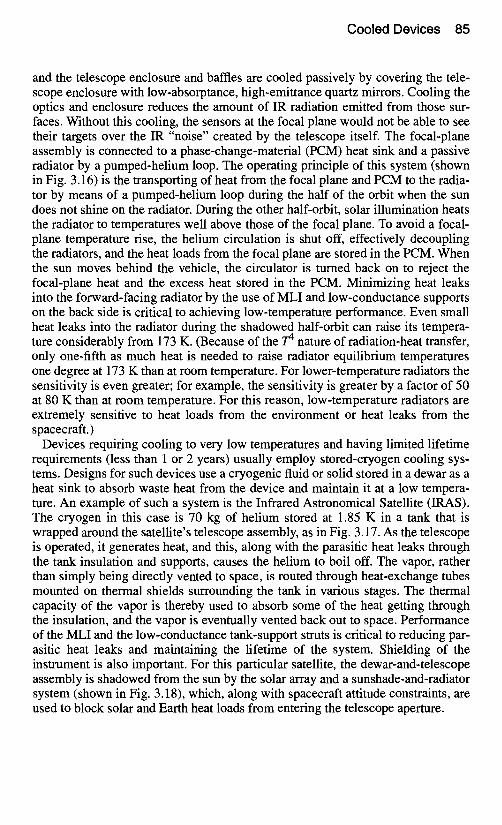
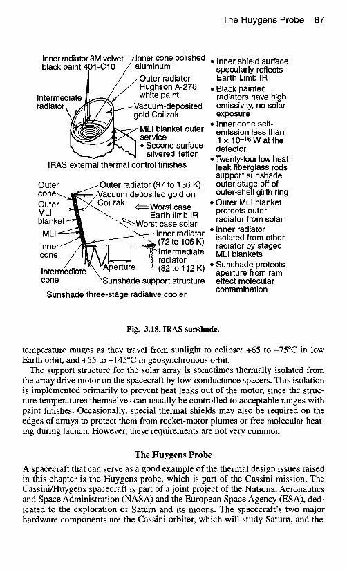
Devices requiring cooling to very low temperatures and having limited lifetime requirements (less than 1 or 2 years) usually employ stored-cryogen cooling sys- tems. Designs for such devices use a cryogenic fluid or solid stored in a dewar as a heat sink to absorb waste heat from the device and maintain it at a low tempera- ture. An example of such a system is the Infrared Astronomical Satellite (IRAS). The cryogen in this case is 70 kg of helium stored at 1.85 K in a tank that is wrapped around the satellite's telescope assembly, as in Fig. 3.17. As the telescope is operated, it generates heat, and this, along with the parasitic heat leaks through the tank insulation and supports, causes the helium to boil off. The vapor, rather than simply being directly vented to space, is routed through heat-exchange tubes mounted on thermal shields surrounding the tank in various stages. The thermal capacity of the vapor is thereby used to absorb some of the heat getting through the insulation, and the vapor is eventually vented back out to space. Performance of the MLI and the low-conductance tank-support struts is critical to reducing par- asitic heat leaks and maintaining the lifetime of the system. Shielding of the instrument is also important. For this particular satellite, the dewar-and-telescope assembly is shadowed from the sun by the solar array and a sunshade-and-radiator system (shown in Fig. 3.18), which, along with spacecraft attitude constraints, are used to block solar and Earth heat loads from entering the telescope aperture.
86 Thermal Design Examples
Sunshade Sunshade support Solar panel / E x t e r n a l structure surface Girth rings Optical / 188 K 171 J( subsyst MLI m 90 K / / ra131~layers
Earth shie~ ~ ~ i J ~ 4 1 1 L I . . . . . //50 K,aEIJ[ ' 15" • 5 p, rings , ~ ~'25 IKnIEIJl u '
Dewar m, ~ 1 / ' ~ = H Flui 2" shell 2 K ,
Main cryogen tank Interface support Supports
structure Spacecraft Vapor-cooled shields
o70 kg He stored at 1.85 K • 2.2 K focal plane • Design life = 1 year • Volume = 311 cm 3 • Dry weight (tankage) = 386 kg
• Instrument heat load = 12.2 mW • Heat leak dominated by supports (55%) • MLI heat leak only 17 % total • Parasitic heat leak:
- Total = 33 mW - Q/A = 0.013 W/m 2
Fig. 3.17. Infrared Astronomical Satellite (IRAS) thermal design.
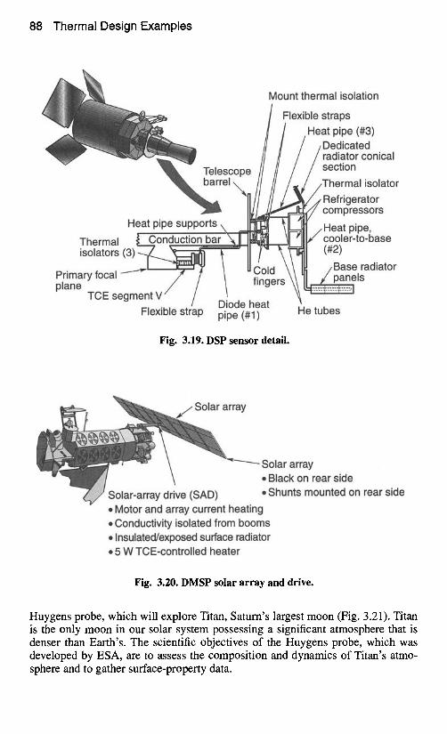
Applications with moderate-to-large cooling requirements and a lifetime in excess of 1 or 2 years normally employ refrigerators. However, refrigerators have drawbacks, which will be discussed in Vol. 2. A sample refrigerator design is the DSP Third Color Experiment cryocooler, shown in Fig. 3.19. Here a refrigerator is mounted in the telescope assembly to provide additional cooling to a set of sen- sors that are mounted on, but conductively isolated from, the primary focal plane. A heat pipe is used to transfer heat from the sensor (TCE Segment V in the figure) to the refrigerator-compressor cold heat pipe, to a radiator mounted on the side of the spacecraft. The temperature boost given by the refrigerator results in a much smaller radiator area because of the T 4 nature of radiation heat transfer. The reduced size and mass of the radiator more than compensate for the mass of the refrigerator and the extra electrical-power-system mass required to run it.
Solar Arrays
Thermal control of solar arrays is generally straightforward. The solar cells pre- clude the use of any thermal finishes on the sun-facing side of the array, so the array's thermal radiative properties are controlled by the high-absorptance, high- emittance solar cells themselves (see Fig. 3.20). To keep array temperatures as low as possible (a practice that increases electrical efficiency), designs usually call for the back of an array to be painted with high-emittance black or white paint. The white paint is used primarily in low-altitude orbits where albedo loads from Earth may illuminate the back side of the array. As a result of their high absorptance, high emittance, large area, and low mass, solar arrays typically cycle through wide
The Huygens Probe 87
Inner radiator 3M velvet / Inner cone polished black paint 4 .01-C10/a luminum • Inner shield surface
specularly reflects ] / /Outer radiator Earth Limb IR
/ ~ Hughson A-276 • Black painted Intermediate ~ white paint radiators have high radiator\ J/1~11 / . ~ Vacuum-deposited emissivity, no solar
~ / f f ' / a ~ ~ gold Coilzak exposure i t ~ ~ ~ MLI blanket outer • Inner cone self- I ~ j < ~ / " , , h service emission less than t, - - " , r ~ I • Second surface 1 x 10 -16 W at the
~ silvered Teflon detector • Twenty-four low heat
IRAS external thermal control finishes leak fiberglass rods support sunshade
Outer Outer radiator (97 to 136 K) outer stage off of cone.....~l~--~/Va outer-shell girth ring cuum deposited gold on Cute - l ~ J ~ Coilzak < ~ Worst case • Outer MLI blanket MLI ---"!"-" . ~ Earth limb IR protects outer b lanke t -~ "'.~..% Worst case solar radiator from solar
MLI ~ ~ Inner radiator • Inner radiator Inner ~ / l ~ j - - ~ _ .- ~ (72 to 106 K) isolated from other
radiator by staged cone / I A A tl I "~/~lntermediate MLI blankets
/ IV \ / 1 - - -~ I I1~ radiator Intermediate ~'k~ vAperture - - (82 to 112 K) ° apertureSUnshadefromPr°teCtSram cone "Sunshade support structure effect molecular
contamination Sunshade three-stage radiative cooler
Fig. 3.18. IRAS sunshade.
temperature ranges as they travel from sunlight to eclipse: +65 to-75°C in low Earth orbit, and +55 to-145°C in geosynchronous orbit.
The support structure for the solar array is sometimes thermally isolated from the array drive motor on the spacecraft by low-conductance spacers. This isolation is implemented primarily to prevent heat leaks out of the motor, since the struc- ture temperatures themselves can usually be controlled to acceptable ranges with paint finishes. Occasionally, special thermal shields may also be required on the edges of arrays to protect them from rocket-motor plumes or free molecular heat- ing during launch. However, these requirements are not very common.
The l-luygens Probe
A spacecraft that can serve as a good example of the thermal design issues raised in this chapter is the Huygens probe, which is part of the Cassini mission. The Cassini/Huygens spacecraft is part of a joint project of the National Aeronautics and Space Administration (NASA) and the European Space Agency (ESA), ded- icated to the exploration of Saturn and its moons. The spacecraft's two major hardware components are the Cassini orbiter, which will study Saturn, and the
88 Thermal Design Examples
Mount thermal isolation
Telescope barrel ,,
Heat pipe supports,
Thermal bar isolators (3)~ _
Primary focal ----~ / / plane
TCE segment V J
Flexible strap
Flexible straps Heat pipe (#3)
Dedicated radiator conical section
~ Thermal isolator
Re fmr ~re~at°~s
Heat pipe, j/cooler-to-base
(#2)
,Base radiator fingers
Diode heat pipe (#1) He tubes
Fig. 3.19. DSP sensor detail.
olar array
Solar array • Black on rear side • Shunts mounted on rear side
• Motor and array current heating • Conductivity isolated from booms • Insulated/exposed surface radiator • 5 W TCE-controlled heater
Fig. 3.20. DMSP solar array and drive.
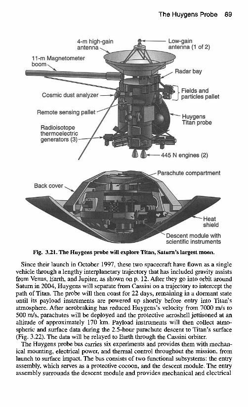
Huygens probe, which will explore Titan, Saturn's largest moon (Fig. 3.21). Titan is the only moon in our solar system possessing a significant atmosphere that is denser than Earth's. The scientific objectives of the Huygens probe, which was developed by ESA, are to assess the composition and dynamics of Titan's atmo- sphere and to gather surface-property data.
The Huygens Probe 89
4-m high-gain antenna
11-m Magnetometer boom ..
Low-gain antenna (1 of 2)
Radar bay
Cosmic dust analyzer
Remote sensing pallet
Radioisotope thermoelectric generators (3)
Back cover
Fields and particles pallet
Huygens Titan probe
445 N engines (2)
Parachute compartment
Heat shield
Descent module with scientific instruments
Fig. 3.21. The Huygens probe will explore Titan, Saturn's largest moon.
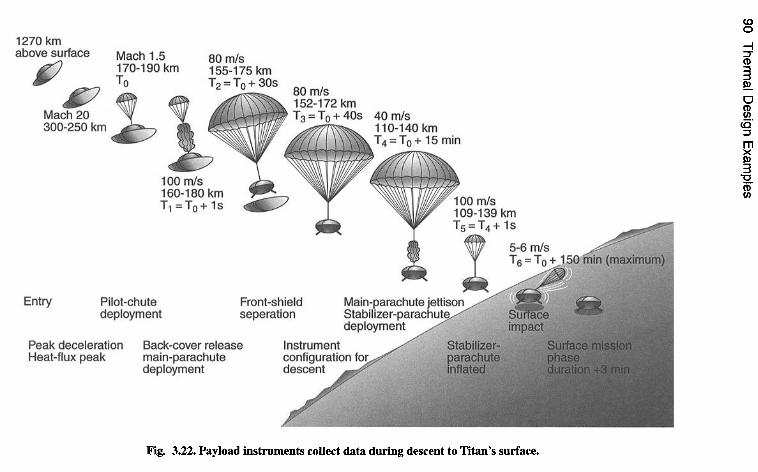
Since their launch in October 1997, these two spacecraft have flown as a single vehicle through a lengthy interplanetary trajectory that has included gravity assists from Venus, Earth, and Jupiter, as shown on p. 12. After they go into orbit around Saturn in 2004, Huygens will separate from Cassini on a trajectory to intercept the path of Titan. The probe will then coast for 22 days, remaining in a dormant state until its payload instruments are powered up shortly before entry into Titan's atmosphere. After aerobraking has reduced Huygens's velocity from 7000 rn/s to 500 m/s, parachutes will be deployed and the protective aeroshell jettisoned at an altitude of approximately 170 km. Payload instruments will then collect atmo- spheric and surface data during the 2.5-hour parachute descent to Titan's surface (Fig. 3.22). The data will be relayed to Earth through the Cassini orbiter.
The Huygens probe bus carries six experiments and provides them with mechan- ical mounting, electrical power, and thermal control throughout the mission, from launch to surface impact. The bus consists of two functional subsystems: the entry assembly, which serves as a protective cocoon, and the descent module. The entry assembly surrounds the descent module and provides mechanical and electrical
90 Therm
al Design Exam
ples
E~
U')+
u~ ii
.m
OC
L
~-~
LI.. u~
Lt~ "~
"0
o6
m
E
o~E~~ ~6~o
,,- ,-
I--
, 0
OQ
.
e-
w
ffl
t- O
"~a
. OK
~a
=t
e,, O
~a
r#} ~a
I=
=1
~a
o I= ~a
,m
O
#.
The Huygens Probe 91
connections to the Cassini orbiter, as well as the heat shields necessary to protect the vehicle during aerobraking in Titan's atmosphere. It also provides some thermal control for the descent module during the cruise and postseparation coast phases.
After the aerobraking maneuver, the entry assembly is jettisoned, exposing the descent module, which coasts through Titan's atmosphere via the deployed para- chutes. The descent module consists of an aluminum shell and two platforms sup- porting the six experiments and bus electronics (Fig. 3.23).
Thermal Design Drivers
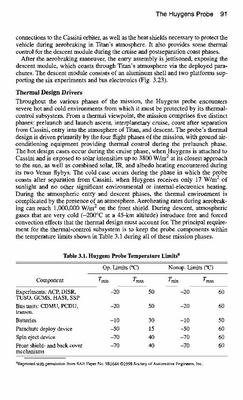
Throughout the various phases of the mission, the Huygens probe encounters severe hot and cold environments from which it must be protected by its thermal- control subsystem. From a thermal viewpoint, the mission comprises five distinct phases: prelaunch and launch ascent, interplanetary cruise, coast after separation from Cassini, entry into the atmosphere of Titan, and descent. The probe's thermal design is driven primarily by the four flight phases of the mission, with ground air- conditioning equipment providing thermal control during the prelaunch phase. The hot design cases occur during the cruise phase, when Huygens is attached to Cassini and is exposed to solar intensifies up to 3800 W/m 2 at its closest approach to the sun, as well as combined solar, IR, and albedo heating encountered during its two Venus flybys. The cold case occurs during the phase in which the probe coasts after separation from Cassini, when Huygens receives only 17 W/m 2 of sunlight and no other significant environmental or internal-electronics heating. During the atmospheric entry and descent phases, the thermal environment is complicated by the presence of an atmosphere. Aeroheating rates during aerobrak- ing can reach 1,000,000 W/m 2 on the front shield. During descent, atmospheric gases that are very cold (-200°C at a 45-km altitude) introduce free and forced convection effects that the thermal design must account for. The principal require- ment for the thermal-control subsystem is to keep the probe components within the temperature limits shown in Table 3.1 during all of these mission phases.
Table 3.1. Huygens Probe Temperature Limits a
Op. Limits (°C) Nonop. Limits (°C)
Component Train Tmax Train Tmax
Experiments: ACE DISR, -20 50 -20 60 TUSO, GCMS, HASI, SSP Bus units: CDMU, PCDU, -20 50 -20 60 transm.
Batteries -10 30 -10 50 Parachute deploy device -50 15 -50 60 Spin eject device -70 40 -70 60
Front shield- and back cover -70 40 -70 60 mechanisms
aReprinted with permission from SAE Paper No. 981644 ©1998 Society of Automotive Engineers, Inc.
92 Thermal Design Examples
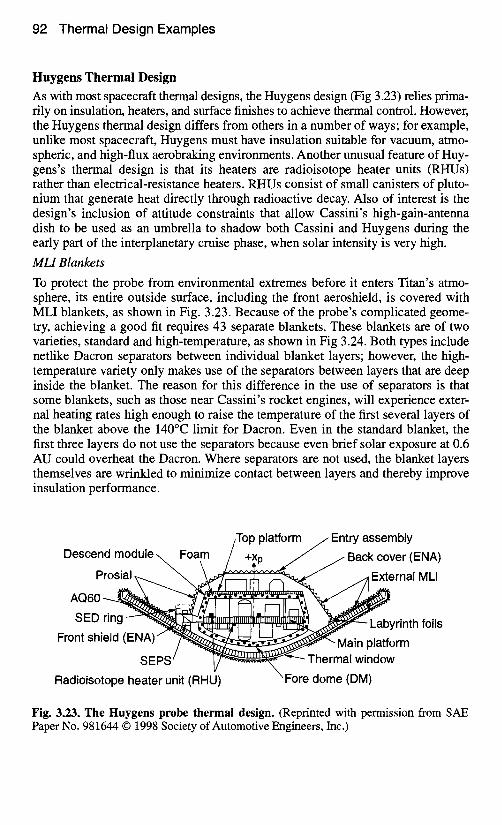
Huygens Thermal Design As with most spacecraft thermal designs, the Huygens design (Fig 3.23) relies prima- rily on insulation, heaters, and surface finishes to achieve thermal control. However, the Huygens thermal design differs from others in a number of ways; for example, unlike most spacecraft, Huygens must have insulation suitable for vacuum, atmo- spheric, and high-flux aerobraking environments. Another unusual feature of Huy- gens's thermal design is that its heaters are radioisotope heater units (RHUs) rather than electrical-resistance heaters. RHUs consist of small canisters of pluto- nium that generate heat directly through radioactive decay. Also of interest is the design's inclusion of attitude constraints that allow Cassini's high-gain-antenna dish to be used as an umbrella to shadow both Cassini and Huygens during the early part of the interplanetary cruise phase, when solar intensity is very high.
MLI Blankets
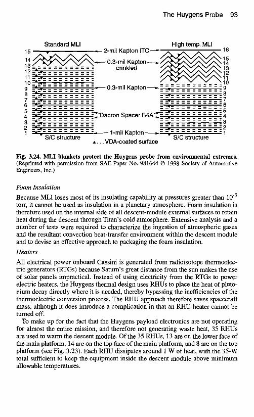
To protect the probe from environmental extremes before it enters Titan's atmo- sphere, its entire outside surface, including the front aeroshield, is covered with MLI blankets, as shown in Fig. 3.23. Because of the probe's complicated geome- try, achieving a good fit requires 43 separate blankets. These blankets are of two varieties, standard and high-temperature, as shown in Fig 3.24. Both types include netlike Dacron separators between individual blanket layers; however, the high- temperature variety only makes use of the separators between layers that are deep inside the blanket. The reason for this difference in the use of separators is that some blankets, such as those near Cassini's rocket engines, will experience exter- nal heating rates high enough to raise the temperature of the first several layers of the blanket above the 140°C limit for Dacron. Even in the standard blanket, the first three layers do not use the separators because even brief solar exposure at 0.6 AU could overheat the Dacron. Where separators are not used, the blanket layers themselves are wrinkled to minimize contact between layers and thereby improve insulation performance.
/Top platform / E n t r y assembly Descend module\ Foam / +Xp / /Back cover (ENA)
P rosii~al ~ . . . . . . . . ~ ~ / j [ Ex~ternal MLI
SED nng ring -~- Front shield ~ ~ ' ~ ! i ~ [ li"l[J ~ ~ Labyrinth f°ils
(ENA) / ~ - ~ Main platform SEPS / V - ' ~ ~ ~ ' ~ Thermal window
Radioisotope heater unit (RHU)
Fig. 3.23. The Huygens probe thermal design. (Reprinted with permission from SAE Paper No. 981644 © 1998 Society of Automotive Engineers, Inc.)
The Huygens Probe 93
Standard MLI High temp. MLI 15 ..,-- 2-mil Kapton ITO ---- 16
14 ~ 0.3-mil Kapton ~ 14 13 12 -A~_ crinkled 13
12 11 -A2.- 11 10 "A~_ 10 9 - i ~ - ~ 0.3-mil Kapton----~_ ~ _ 9 8 -AL•- ~.., ~ _ 8 7 -A~_ 7 6 ZII~I II I ~I 6
5 -A..~_ 5 4 -A~_ ~Dacron Spacer B 4 A ~ = _ ~-i 4 3 -A...v- 3 - . W I
2 -A..~_ 2 - - . , - V ==.
1 1-mil Kapton ~ • S/C structure 1 -A • S/C structure A. . . VDA-coated surface
Fig. 3.24. MLI blankets protect the Huygens probe from environmental extremes. (Reprinted with permission from SAE Paper No. 981644 © 1998 Society of Automotive Engineers, Inc.)
Foam Insulation
Because MLI loses most of its insulating capability at pressures greater than 10 -3 torr, it cannot be used as insulation in a planetary atmosphere. Foam insulation is therefore used on the internal side of all descent-module external surfaces to retain heat during the descent through Titan's cold atmosphere. Extensive analysis and a number of tests were required to characterize the ingestion of atmospheric gases and the resultant convection heat-transfer environment within the descent module and to devise an effective approach to packaging the foam insulation.
Heaters
All electrical power onboard Cassini is generated from radioisotope thermoelec- tric generators (RTGs) because Saturn's great distance from the sun makes the use of solar panels impractical. Instead of using electricity from the RTGs to power electric heaters, the Huygens thermal design uses RHUs to place the heat of pluto- nium decay directly where it is needed, thereby bypassing the inefficiencies of the thermoelectric conversion process. The Pd-IU approach therefore saves spacecraft mass, although it does introduce a complication in that an RHU heater cannot be turned off.
To make up for the fact that the Huygens payload electronics are not operating for almost the entire mission, and therefore not generating waste heat, 35 RHUs are used to warm the descent module. Of the 35 RHUs, 13 are on the lower face of the main platform, 14 are on the top face of the main platform, and 8 are on the top platform (see Fig. 3.23). Each RHU dissipates around 1 W of heat, with the 35-W total sufficient to keep the equipment inside the descent module above minimum allowable temperatures.
94 Thermal Design Examples
Thermal Window
Because Huygens is entirely covered by MLI, and predicting MLI's effectiveness with any precision is difficult, a thermal "window" was placed in the insulation near the apex of the front shield, as shown in Fig. 3.23. The window provides a known heat leak, which ensures that the RHUs will not overheat internal compo- nents if the MLI insulation performs better than nominally expected. The window
consists of a cut-out in the MLI that exposes a 0.165-m 2 area of the front shield that is covered by a thin aluminum plate. The plate is painted white to provide a high emittance while minimizing the effect of any solar illumination. The inside surface of the shield and the outside surface of the descent module are both painted black in this area to improve the radiative heat-transfer path from the descent module to the window.
Aeroshield
The purpose of the aeroshield is to provide an appropriately shaped structure to produce the desired deceleration forces during the probe's entry into Titan's atmo- sphere and to protect the probe from the very high heating rates encountered dur- ing this mission phase. The aeroshield structure is composed of a central aluminum nose cap surrounded by a conical aluminum honeycomb cone. Because Huygens's MLI covering is constructed of materials that cannot survive high tem- peratures, that covering will burn off shortly after the start of the entry phase. Thermal protection is therefore provided by an 18-mm-thick layer of AQ60 abla- tive material on the front surface of the aeroshield plus a 2-mm-thick layer of Pro- sial on the rear side of the aeroshield and the outside of the entry module back cover, as indicated in Fig. 3.23. Ablative materials are typically used on entry shields because the charring and vaporization process allows a tremendous amount of heat to be absorbed with minimal mass. In some cases, heating rates are so high that no material could survive, making the sacrifice of an ablative layer the only practical means of surviving atmospheric entry.
Gap Closeout
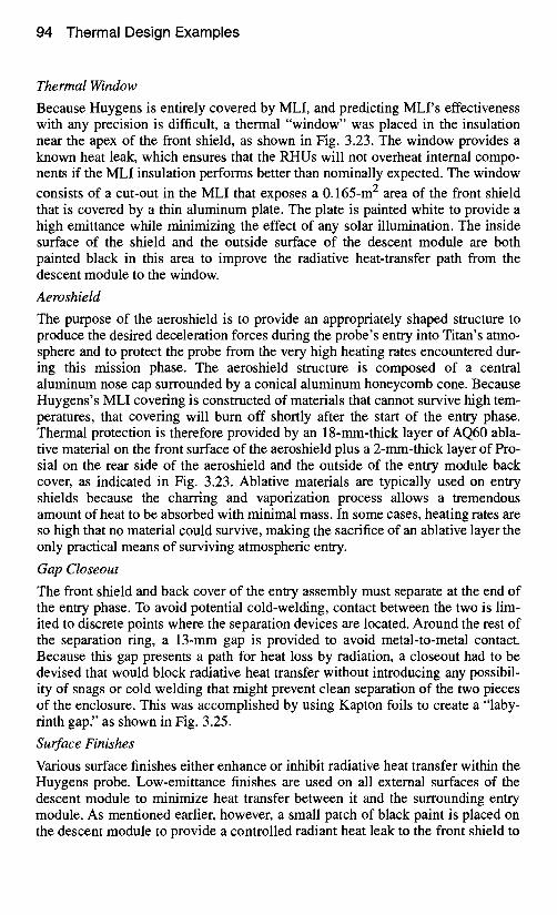
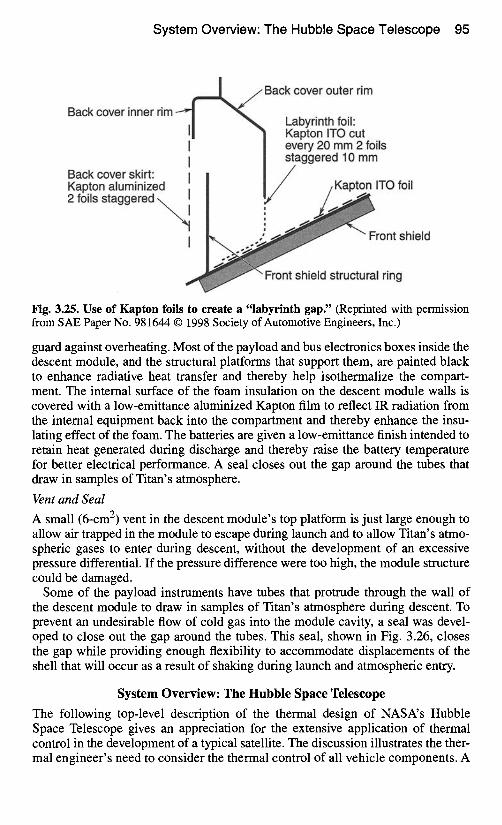
The front shield and back cover of the entry assembly must separate at the end of the entry phase. To avoid potential cold-welding, contact between the two is lim- ited to discrete points where the separation devices are located. Around the rest of the separation ring, a 13-mm gap is provided to avoid metal-to-metal contact. Because this gap presents a path for heat loss by radiation, a closeout had to be devised that would block radiative heat transfer without introducing any possibil- ity of snags or cold welding that might prevent clean separation of the two pieces of the enclosure. This was accomplished by using Kapton foils to create a "laby- rinth gap," as shown in Fig. 3.25.
Surface Finishes
Various surface finishes either enhance or inhibit radiative heat transfer within the Huygens probe. Low-emittance finishes are used on all external surfaces of the descent module to minimize heat transfer between it and the surrounding entry module. As mentioned earlier, however, a small patch of black paint is placed on the descent module to provide a controlled radiant heat leak to the front shield to
System Overview: The Hubble Space Telescope 95
Back cover inner rim ----" I
'% Back cover outer rim
I Labyrinth foil" Kapton ITO cut every 20 mm 2 foils
I ,,staggered 10 mm Back cover skirt: I Kapton aluminized / Kapton ITO foil 2 foils staggered - . ~ i ~ l ~
Front shield
Front shield structural ring
Fig. 3.25. Use of Kapton foils to create a "labyrinth gap" (Reprinted with permission from SAE Paper No. 981644 © 1998 Society of Automotive Engineers, Inc.)
guard against overheating. Most of the payload and bus electronics boxes inside the descent module, and the structural platforms that support them, are painted black to enhance radiative heat transfer and thereby help isothermalize the compart- ment. The internal surface of the foam insulation on the descent module walls is covered with a low-emittance aluminized Kapton film to reflect IR radiation from the internal equipment back into the compartment and thereby enhance the insu- lating effect of the foam. The batteries are given a low-emittance finish intended to retain heat generated during discharge and thereby raise the battery temperature for better electrical performance. A seal closes out the gap around the tubes that draw in samples of Titan's atmosphere.
Vent and Seal
A small (6-cm 2) vent in the descent module's top platform is just large enough to allow air trapped in the module to escape during launch and to allow Titan's atmo- spheric gases to enter during descent, without the development of an excessive pressure differential. If the pressure difference were too high, the module structure could be damaged.
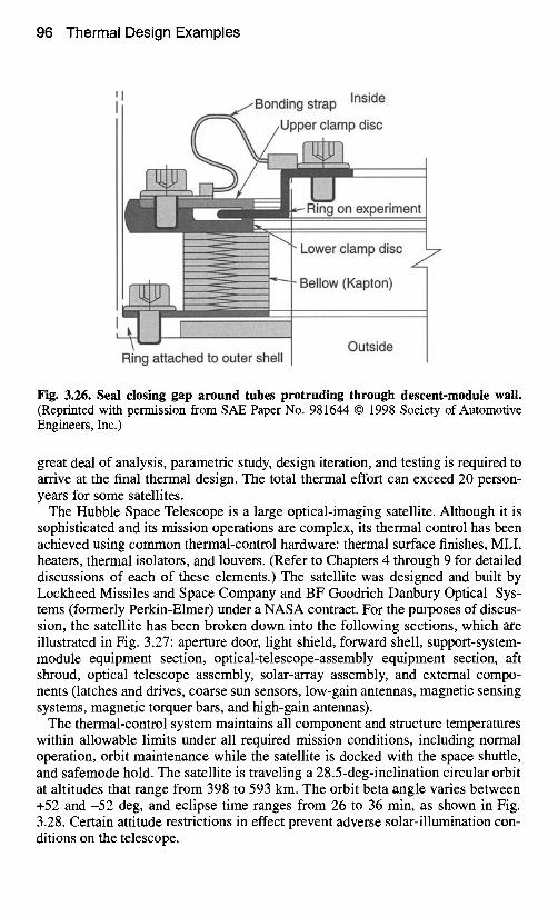
Some of the payload instruments have tubes that protrude through the wall of the descent module to draw in samples of Titan's atmosphere during descent. To prevent an undesirable flow of cold gas into the module cavity, a seal was devel- oped to close out the gap around the tubes. This seal, shown in Fig. 3.26, closes the gap while providing enough flexibility to accommodate displacements of the shell that will occur as a result of shaking during launch and atmospheric entry.
System Overview: The Hubble Space Telescope
The following top-level description of the thermal design of NASA's Hubble Space Telescope gives an appreciation for the extensive application of thermal control in the development of a typical satellite. The discussion illustrates the ther- mal engineer's need to consider the thermal control of all vehicle components. A
96 Thermal Design Examples
Bonding strap Inside
/Upper clamp disc
Ring attached to outer shell
/P -Ring on experiment
Lower clamp disc 7
Bellow (Kapton)
Outside
Fig. 3.26. Seal closing gap around tubes protruding through descent-module wall. (Reprinted with permission from SAE Paper No. 981644 © 1998 Society of Automotive Engineers, Inc.)
great deal of analysis, parametric study, design iteration, and testing is required to arrive at the final thermal design. The total thermal effort can exceed 20 person- years for some satellites.
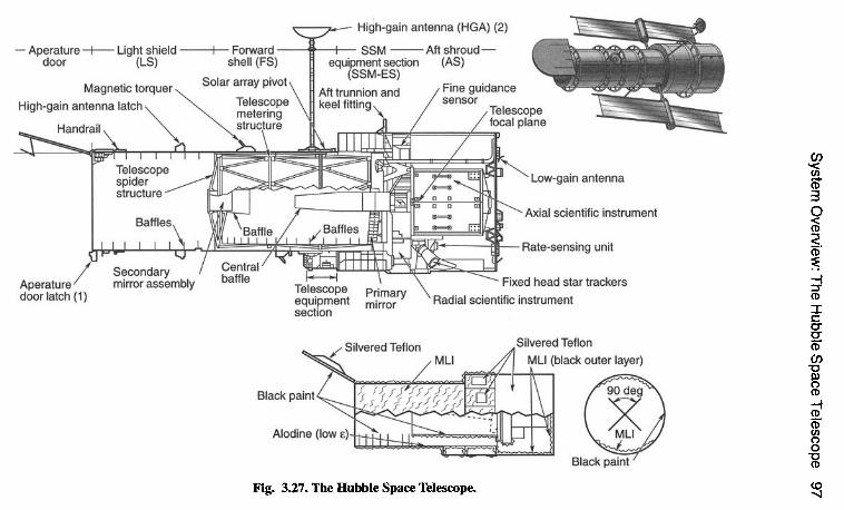
The Hubble Space Telescope is a large optical-imaging satellite. Although it is sophisticated and its mission operations are complex, its thermal control has been achieved using common thermal-control hardware: thermal surface finishes, MLI, heaters, thermal isolators, and louvers. (Refer to Chapters 4 through 9 for detailed discussions of each of these elements.) The satellite was designed and built by Lockheed Missiles and Space Company and BF Goodrich Danbury Optical Sys- tems (formerly Perkin-Elmer) under a NASA contract. For the purposes of discus- sion, the satellite has been broken down into the following sections, which are illustrated in Fig. 3.27: aperture door, light shield, forward shell, support-system- module equipment section, optical-telescope-assembly equipment section, aft shroud, optical telescope assembly, solar-array assembly, and external compo- nents (latches and drives, coarse sun sensors, low-gain antennas, magnetic sensing systems, magnetic torquer bars, and high-gain antennas).
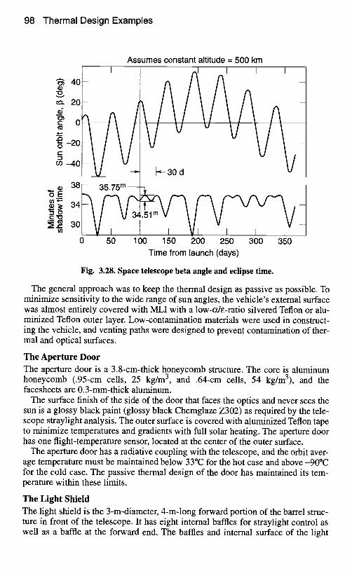
The thermal-control system maintains all component and structure temperatures within allowable limits under all required mission conditions, including normal operation, orbit maintenance while the satellite is docked with the space shuttle, and safemode hold. The satellite is traveling a 28.5-deg-inclination circular orbit at altitudes that range from 398 to 593 km. The orbit beta angle varies between +52 and-52 deg, and eclipse time ranges from 26 to 36 min, as shown in Fig. 3.28. Certain attitude restrictions in effect prevent adverse solar-illumination con- ditions on the telescope.
System O
verview: The H
ubble Space Telescope
97
I q tl( 0
0
-- 0
0-
(I) ~
-- A
0
(I)~
c --~
co N
g
~
r-
e 0
-._~ ~
.~
(-
E
e l- e
- .-
_~
a
) "-
~ o
t- e
- ,_
.-
~
, _
~
e--
o
._~
II ~
~..__~
__~.~
j
Ihl( ~ I~ll
°° I I
1 ~
/
~ l~
ffl ~,1-. V
i 1~'5 g
.m
0 ~
-
LL
~
L
co -I
~-o
~ ~
~.._. o
~- ~g
rn
I o
p
p ~
- 8 "~
*'° ~
e- ID
O
< ~
~o
.9o _~
"{3
t'~
$- >
:~_,J I~
--J {I L.,\ \
~! ~ ~
el
0
El
/ ;
0.)
~o ¢-
"0
0 1
. <
0 ca
~a
~a
=1
~a
[- i<
E.
98 Thermal Design Examples
Assumes constant altitude = 500 km r
"~ 40
,'~ 20 ¢f
0
-20 O
g m -40
O ° m ,
[
38
34
30
0 I I
50 100 150 200 250 300 350 Time from launch (days)
Fig. 3.28. Space telescope beta angle and eclipse time.
The general approach was to keep the thermal design as passive as possible. To minimize sensitivity to the wide range of sun angles, the vehicle's external surface was almost entirely covered with MLI with a low-cx&-ratio silvered Teflon or alu- minized Teflon outer layer. Low-contamination materials were used in construct- ing the vehicle, and venting paths were designed to prevent contamination of ther- mal and optical surfaces.
The Aperture Door The aperture door is a 3.8-cm-thick honeycomb structure. The core is aluminum honeycomb (.95-cm cells, 25 kg/m 3, and .64-cm cells, 54 kg/m3), and the facesheets are 0.3-mm-thick aluminum.
The surface finish of the side of the door that faces the optics and never sees the sun is a glossy black paint (glossy black Chemglaze Z302) as required by the tele- scope straylight analysis. The outer surface is covered with aluminized Teflon tape to minimize temperatures and gradients with full solar heating. The aperture door has one flight-temperature sensor, located at the center of the outer surface.
The aperture door has a radiative coupling with the telescope, and the orbit aver- age temperature must be maintained below 33°C for the hot case and above-90°C for the cold case. The passive thermal design of the door has maintained its tem- perature within these limits.
The Light Shield The light shield is the 3-m-diameter, 4-m-long forward portion of the barrel struc- ture in front of the telescope. It has eight internal baffles for straylight control as well as a baffle at the forward end. The baffles and internal surface of the light
System Overview: The Hubble Space Telescope 99
shield are coated with an optical black paint (fiat black Chemglaze Z306) as required by the telescope straylight analysis. The ~ e ratio of the black paint is 0.95/0.92. The external surface of the light shield is covered with MLI blankets (an outer layer of aluminized Teflon, 15 layers of .008-mm embossed double-alu- minized Kapton, and an inner layer of .025-mm single-aluminized Kapton). An effective emittance of 0.02 has been used for the MLI blankets. The MLI blankets are mounted on the structure to reduce the structural temperature variation, and they also function as part of the meteoroid protection system. There are eight flight-temperature sensors on the light-shield structures. This design meets the orbit-average temperature requirement o f -33 to -59°C.
The Forward Shell
The forward shell is a 3-m-diameter, 3-m-long cylinder that encloses the telescope assembly. The forward-shell internal surface finish is alodine with an emittance of approximately 0.15. The external surfaces are covered with MLI blankets identi- cal to the light-shield MLI blankets (an outer layer of aluminized Teflon, 15 layers of .008-mm embossed double-aluminized Kapton, and an inner layer of .025-mm single-aluminized Kapton). The MLI covers the external tings except for the structural ring at station 358, which is covered with aluminized Teflon. The for- ward shell has eight flight-temperature sensors. Temperature of the forward shell is maintained between-23 and-53°C on an orbit-average basis.
The Support-System-Module Equipment Section
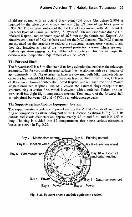
The support-system-module equipment section (SSM-ES) consists of an annular ring of compartments surrounding part of the telescope, as shown in Fig. 3.27. Its outside and inside diameters are approximately 4.3 m and 3 m, and it is 1.53 m long. The ring is divided into 12 compartments that house various electronics boxes, as shown in Fig. 3.29.
Bay 7 - Mechanism c o ~ " E J E - ~
Bay 6 - Reaction w h ~ ~ ~
Bay 5 - Communications
Bay 4 - P o w e r ~
Bay 3 - Power
~ay 8 - Pointing control
9 - Reaction wheel
Bay 10- SI control and data handling
3ay 1 - Data management
Bay 2 - Power
Fig. 3.29. Support-system-module equipment section.
100 Thermal Design Examples
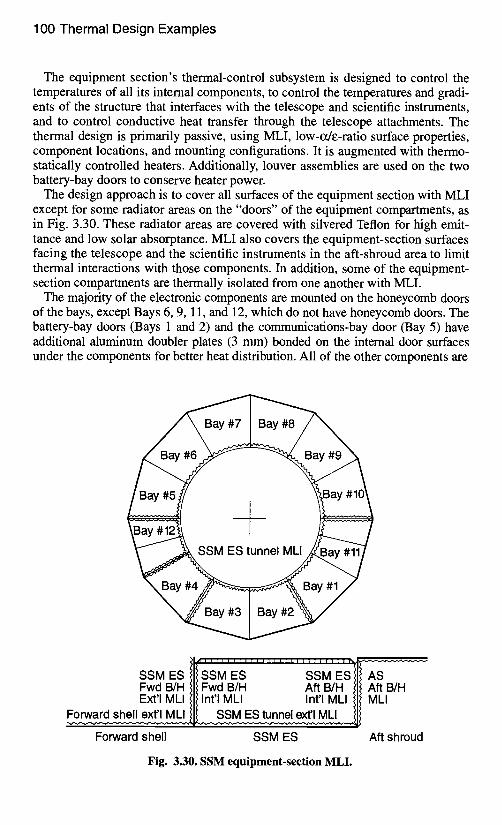
The equipment section's thermal-control subsystem is designed to control the temperatures of all its intemal components, to control the temperatures and gradi- ents of the structure that interfaces with the telescope and scientific instruments, and to control conductive heat transfer through the telescope attachments. The thermal design is primarily passive, using MLI, low-ode-ratio surface properties, component locations, and mounting configurations. It is augmented with thermo- statically controlled heaters. Additionally, louver assemblies are used on the two battery-bay doors to conserve heater power.
The design approach is to cover all surfaces of the equipment section with MLI except for some radiator areas on the "doors" of the equipment compartments, as in Fig. 3.30. These radiator areas are covered with silvered Teflon for high emit- tance and low solar absorptance. MLI also covers the equipment-section surfaces facing the telescope and the scientific instruments in the aft-shroud area to limit thermal interactions with those components. In addition, some of the equipment- section compartments are thermally isolated from one another with MLI.
The majority of the electronic components are mounted on the honeycomb doors of the bays, except Bays 6, 9, 11, and 12, which do not have honeycomb doors. The battery-bay doors (Bays 1 and 2) and the communications-bay door (Bay 5) have additional aluminum doubler plates (3 mm) bonded on the internal door surfaces under the components for better heat distribution. All of the other components are
Bay #6
SSM ES tunnel MLI
SSMES/ Fwd BIH )If Fwcl B/I--I .Aft BIH Ill Aft BIH Ext'l MLI Ill Int'!MLI _ Int'l MU Ill M,i
Forward shell SSM ES Aft shroud
Fig. 3.30. SSM equipment-section MLI.
System Overview: The Hubble Space Telescope 101
mounted directly on the door or mounted on the structure at the bottom of the bay called the "tunnel structure" Along the bottom of the bay are structural beams with additional members for mounting components. The reaction-wheel assem- blies (RWA) have separate mounting structures to provide the correct orientation.
Thermostatically controlled heaters, if needed, maintain minimum temperatures during normal component operation, and they maintain survival temperatures dur- ing times when components are not operating. The batteries have integral internal heater systems. Heaters are mounted on the RWAs, and the remaining equipment- section heaters are mounted on the doors or component mounting structures. Six- teen primary heater circuits are used for the equipment section: one circuit for the computer in Bay 1; one circuit for each of the six batteries in Bays 2 and 3; one circuit for Bay 4; one circuit for the tape recorders in Bay 5; one circuit for the communication equipment in Bay 5; one circuit for each of the four RWAs in Bays 6 and 9; one circuit for the Bay 7 and Bay 8 door heaters, plus the tape recorder in Bay 8; and one circuit for the scientific-instrument electronics trays in Bay 10. Sixteen secondary heater circuits serve as backup. Several heater circuits control more than one heater system: the Bay 5 tape-recorder circuit has two tape- recorder heater systems; the communication circuit has two separate heater sys- tems on the tray; each RWA circuit has separate heater systems for the inboard and outboard bearing; Bay 7 and Bay 8 are on one heater circuit, with heater systems on the Bay 7 door, Bay 8 door, and the tape-recorder mounting structure; and the scientific-instrument electronics circuit has two heater systems on the tray.
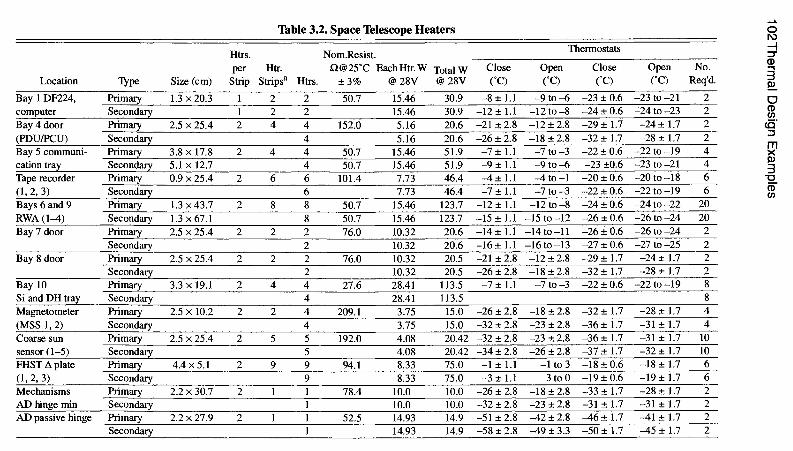
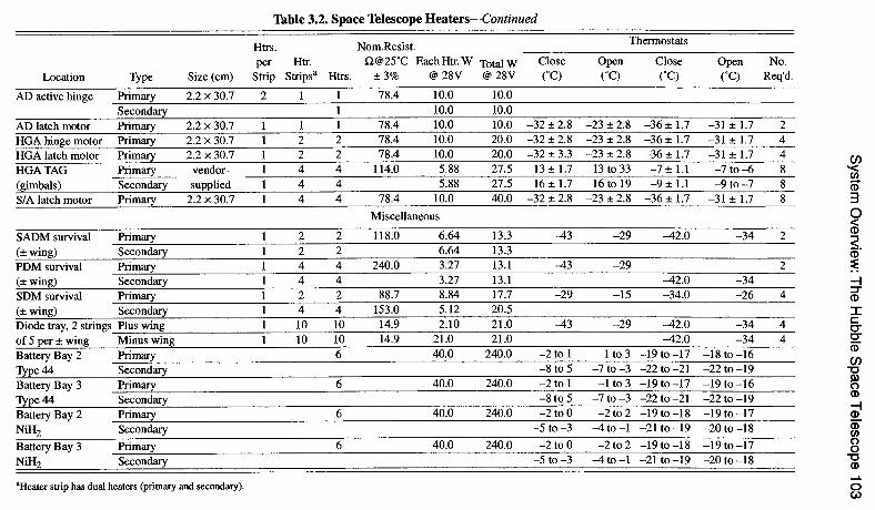
Each heater system, both primary and secondary, has two thermostats wired in series with its heater elements. The systems are thereby protected against open heaters, thermostats, or wires. The second thermostat wired in series will back up a failed closed thermostat in either the primary or the secondar-y system. Two independent failures are required to disable these heater systems. The primary and secondary heater elements can be on the same strip. If a second heater strip is present, the primary heaters are wired in parallel with the secondar-y heaters. Table 3.2 lists all Space Telescope heaters. These heaters were enabled prior to launch, and their status was verified with the first available telemetry data received during deployment operations from the space shuttle.
Many of the electronic components in the equipment section have no internal temperature sensors. To provide temperature data for these components, 20 tem- perature sensors have been placed near the interface of these components and their respective mounting structures.
The following sections describe the thermal designs of selected bays in the equipment section. Bay 1 is a typical electronics-box bay, with a fairly wide range of allowable temperatures, and its design uses radiator area on the door, MLI, and heaters to achieve thermal control. Bays 2 and 3 contain NiH 2 batteries, which must be controlled within a relatively narrow temperature range (-5 to +20°C). MLI, heaters, radiator areas, louvers, and aluminum doublers are used on these bays. Bays 7 and 8 have relatively low levels of electronic waste heat to dissipate and therefore have no radiators; these bays rely on MLI and heaters to keep com- ponents within temperature limits.
102Th
ermal
Desig
n
Exam
ples
o
e4
,-..~ I ce~
I
+1 ¸ +1 I
+1 +1
c,l I
t~ ,
~xl t'-I
m.
t'N
X
m.
c',l
~,.~
+
Ii +I
t-:.
+1
c,i +1 I
t',l +1 I
~ t",l
,-:. ,-.
tN
×
r,¢l
O
O
+1 +1
• 0
+1 +1
, °
c,l • °
X
X
r~
O
O
I I
O
O
+1 +1
~ I c',1
"2."2.
• H +1
t~
t~
c,l ×
I I
O
r~
t'N
+11
Q I
"2.
+1 I
r-:.
c,,I
p., t~
•
°
• °
X
X
m.m
.
r~
~ ("4
+1 +1
C',I ~
I I
I I
+1 +1
I I
ce~ ~
~.m
.
t~
c-,I
t~
1¢3 (',1 ×
p.,
O
c-,I +1
O
O
I +1
o
+1 +1
~ien
~-,li
I
I
+1 +1
m.~
.
t~
X
m.
r~
r~
t ~ t'~
•
°
+1 +1
+1 +1
+1 +1
~ c-,I
I I
+I +I
~. o.
o.
t",l
×
r~
,.~
,-; ,_.;
+li+
l +I
+I
+1 +1
+11+1
t",l C
'I ~Q
~ O
+1 +1
,.. e¢~
m~
I
II
+i *il +i
O4
',~t" "~" o~
oo
o. ,~
c',,l c',,l
c'4 ×
×
c'4
~N
~ m
~r~
M
("4 • °
+I +I
+1 +1
c,l c,l
+I +I
+1 +1
~ m
I
I
o.o
. O
O
O
~
m ×
cxl
u =
~<
System
Overview
: The Hubble S
pace Telescope 103
O
~a
~a
f~
~a m ,=
-H
+1
I I
-H
+1
I I
~o
oo
-H
-H
-H-H
cq
m" I ~
o
I -H
+1
I
~o
-H
-H
0o
~o ~t"
r~
X
c',l
E
t,
L~
+1
I E
~?
O
~D
m"
m" I
I I
I
-T(7
-T~7 o~
c,I I
m"
m"
~o
c~
I I
o~
c~l
I I
O~
cq
I I I
m"
m"
r- ~J
I O
O~
~o I Q
o~ I c~
oo
r~
I I
O
(o~
I I
,-~ L"91
I o I
° o
.~.- Z
~:
~o I
o~ I I o O
.=. Z
o
,=
104 Thermal Design Examples
Bay 1
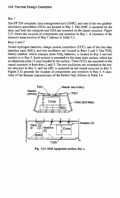
The DF 224 computer, data management unit (DMU), and one of the two gimbal- electronics assemblies (GEA) are located in Bay 1. The DMU is mounted on the door, and both the computer and GEA are mounted on the tunnel structure. Figure 3.31 shows the location of components and monitors in Bay 1. A summary of the thermal characteristics of Bay 1 follows in Table 3.3.
Bays 2 and 3
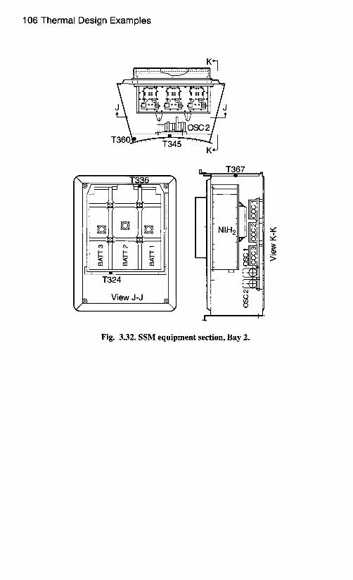
Nickel-hydrogen batteries, charge current controllers (CCC), one of the four data interface units (DIU), and two oscillators are located in Bays 2 and 3. One NiH 2 battery module, which contains three NiH 2 batteries, is located in Bay 2 and one module is in Bay 3. Each module is mounted on the inner door surface, which has an aluminum plate (3 mm) bonded to the surface. Three CCCs are mounted on the tunnel structure in both Bays 2 and 3. The two oscillators are mounted on the tun- nel structure in Bay 2, and the DIU is mounted on the tunnel structure in Bay 3. Figure 3.32 presents the location of components and monitors in Bay 2. A sum- mary of the thermal characteristics of the battery bays follows in Table 3.4.
T351 \ / Heater secondary Heater ~ \ / primary ~'-~--,..,-~, -~ - i E . ~ T 357
i '
Comp ~ T364 (Mid Web)
. I,, ' ,,1 ' ,,1,, - I 'D I i i i i i | ,
1 f i i= II ~ Heaters (2) L k 0 . . . .
Heaters o o Comp 1(2) 0
Jr..., ,I L
'l r r 7 "
T335 /
Fig. 3.31. SSM equipment section, Bay 1.
System Overview: The Hubble Space Telescope 105
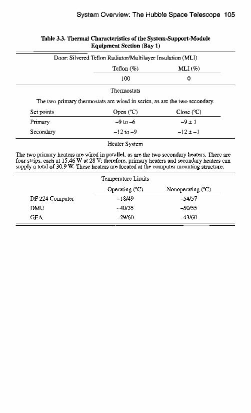
Table 3.3. Thermal Characteristics of the System-Support-Module Equipment Section (Bay 1)
Door: Silvered Teflon Radiator/Multilayer Insulation (MLI)
Teflon (%) MLI (%)
100 0
Thermostats
The two primary thermostats are wired in series, as are the two secondary.
Set points Open (°C) Close (°C)
Primary -9 to -6 -9 _+ 1
Secondary -12 to -9 -12 _+ - 1
Heater System
The two primary heaters are wired in parallel, as are the two secondary heaters. There are four strips, each at 15.46 W at 28 V; therefore, primary heaters and secondary heaters can supply a total of 30.9 W. These heaters are located at the computer mounting structure.
Temperature Limits
Operating (°C) Nonoperating (°C)
DF 224 Computer -18/49 -54/57
DMU --40/35 -50/55
GEA -29/60 --43/60
106 Thermal Design Examples
~ r - ' ~ , , , 7 ~
T36@-,""~ t345 ~~K J
I 1_ l____
U
.£-.
T367
N I H 2
o
Fig. 3.32. SSM equipment section, Bay 2.
,b
System Overview: The Hubble Space Telescope 107
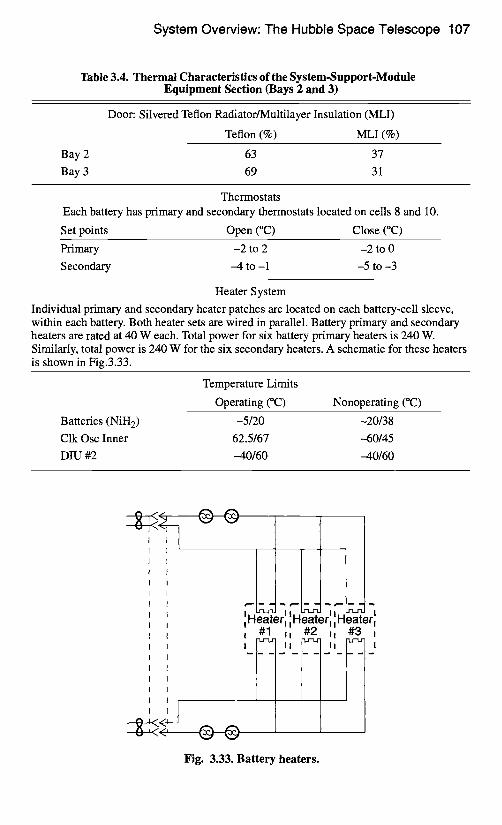
Table 3.4. Thermal Characteristics of the System-Support-Module Equipment Section (Bays 2 and 3)
Bay 2
Bay 3
Door: Silvered Teflon Radiator/Multilayer Insulation (MLI)
Teflon (%) MLI (%)
63 37
69 31
Thermostats Each battery has primary and secondary thermostats located on cells 8 and 10.
Set points Open (°C) Close (°C)
Primary -2 to 2 -2 to 0
Secondary -4 to-1 -5 to-3
Heater System
Individual primary and secondary heater patches are located on each battery-cell sleeve, within each battery. Both heater sets are wired in parallel. Battery primary and secondary heaters are rated at 40 W each. Total power for six battery primary heaters is 240 W. Similarly, total power is 240 W for the six secondary heaters. A schematic for these heaters is shown in Fig.3.33.
Temperature Limits
Operating (°C) Nonoperating (°C)
Batteries (NiH 2) -5/20 -20/38
Clk Osc Inner 62.5/67 --60/45
DIU #2 --40/60 --40/60
.
I ,,
Fig. 3.33. Battery heaters.
108 Thermal Design Examples
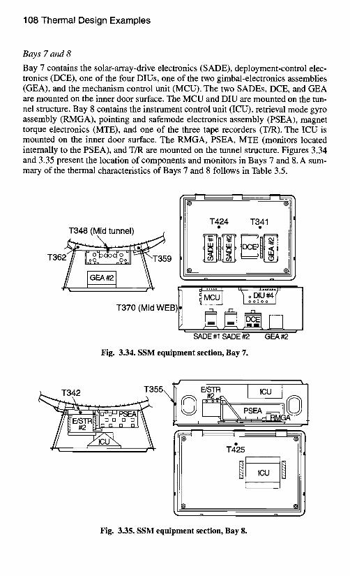
Bays 7 and 8
Bay 7 contains the solar-array-drive electronics (SADE), deployment-control elec- tronics (DCE), one of the four DIUs, one of the two gimbal-electronics assemblies (GEA), and the mechanism control unit (MCU). The two SADEs, DCE, and GEA are mounted on the inner door surface. The MCU and DIU are mounted on the tun- nel structure. Bay 8 contains the instrument control unit (ICU), retrieval mode gyro assembly (RMGA), pointing and safemode electronics assembly (PSEA), magnet torque electronics (MTE), and one of the three tape recorders (T/R). The ICU is mounted on the inner door surface. The RMGA, PSEA, MTE (monitors located internally to the PSEA), and T/R are mounted on the tunnel structure. Figures 3.34 and 3.35 present the location of components and monitors in Bays 7 and 8. A sum- mary of the thermal characteristics of Bays 7 and 8 follows in Table 3.5.
T348 (Mid tunnel)
~ E #1 SADE #2 G ~ #2
Fig. 3.34. SSM equipment section, Bay 7.
T4"25
ICU
I-I r ' l •
Fig. 3.35. SSM equipment section, Bay 8.
System Overview: The Hubble Space Telescope 109
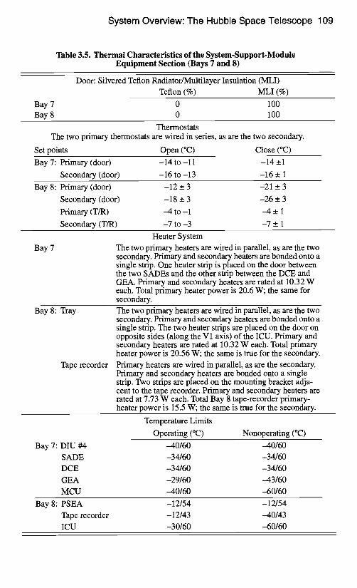
Table 3.5. Thermal Characteristics of the System-Support-Module Equipment Section (Bays 7 and 8)
Bay 7 Bay 8
Door: Silvered Teflon Radiator/Multilayer Insulation (MLI) Teflon (%) MLI (%)
0 100 0 100
Thermostats The two primary thermostats are wired in series, as are the two secondary.
Set points Open (°C) Close (°C)
Bay 7: Primary (door) -14 to-11 -14 +_1
Secondary (door) -16 to -13 -16 _ 1
Bay 8: Primary (door) -12 __ 3 -21 _+ 3
Secondary (door) -18 _ 3 -26 __. 3
Primary (T/R) -4 to-1 -4 __. 1
Secondary (T/R) -7 to -3 -7 +_ 1
Bay 7
Heater System
The two primar-y heaters are wired in parallel, as are the two secondary. Primary and secondary heaters are bonded onto a single strip. One heater strip is placed on the door between the two SADEs and the other strip between the DCE and GEA. Primary and secondary heaters are rated at 10.32 W each. Total primary heater power is 20.6 W; the same for secondary.
Bay 8: Tray
Tape recorder
The two primary heaters are wired in parallel, as are the two secondary. Primary and secondary heaters are bonded onto a single strip. The two heater strips are placed on the door on opposite sides (along the V1 axis) of the ICU. Primary and secondary heaters are rated at 10.32 W each. Total primary heater power is 20.56 W; the same is true for the secondary.
Primary heaters are wired in parallel, as are the secondary. Primary and secondary heaters are bonded onto a single strip. Two strips are placed on the mounting bracket adja- cent to the tape recorder. Primary and secondary heaters are rated at 7.73 W each. Total Bay 8 tape-recorder primary- heater power is 15.5 W; the same is true for the secondary.
Bay 7:
Temperature Limits
Operating (°C) Nonoperating (°C)
DIU #4 -40/60 -40/60
SADE -34/60 -34/60
DCE -34/60 -34/60
GEA -29/60 -43/60
MCU -40/60 -60/60
Bay 8: PSEA -12/54 -12/54
Tape recorder - 12/43 --40/43
ICU -30/60 -60/60
1 10 Thermal Design Examples
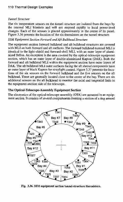
Tunnel Structure
The six temperature sensors on the tunnel structure are isolated from the bays by the internal MLI blankets and will not respond rapidly to local power-level changes. Each of the sensors is placed approximately in the center of its panel. Figure 3.36 presents the location of the six thermistors on the tunnel structure.
SSM Equipment Section Forward and Aft Bulkhead Structure
The equipment section forward bulkhead and aft bulkhead structures are covered with MLI on both forward and aft surfaces. The forward bulkhead external MLI is identical to the light-shield and forward-shell MLI, with an outer layer of alumi- nized Teflon. An exception is the area covered by the optical-telescope equipment section, which has an outer layer of double-aluminized Kapton (DAK). Both the forward and aft bulkhead MLI within the equipment section have outer layers of DAK. The aft bulkhead MLI outer surfaces facing the aft shroud components have an outer layer of black Kapton for straylight control. Figure 3.37 presents the loca- tions of the six sensors on the forward bulkhead and the five sensors on the aft bulkhead. These are generally located close to the center of the bay. There are six additional sensors on the aft bulkhead to monitor the axial and tangential links to the equipment-section side of the telescope.
The Optical-Telescope-Assembly Equipment Section
The electronics of the optical-telescope assembly (OTA) are mounted in an equip- ment section. It consists of several compartments forming a section of a ring around
Bay
Bay #6
T42/\ Bay #7 Bay #8 T348 • T342~ Bay #9
3ay
Bay #12 Bay #11
/ Bay #3 [ Bay #2 T325 I
Bay #1
Fig. 3.36. SSM equipment section tunnel-structure thermistors.
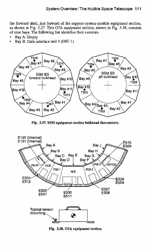
System Overview: The Hubble Space Telescope 111
the forward shell, just forward of the support-system-module equipment section, as shown in Fig. 3.27. This OTA equipment section, shown in Fig. 3.38, consists of nine bays. The following list identifies their contents. • Bay A: Empty • Bay B" Data interface unit 1 (DIU 1)
SSM ES aft bulkhead
Fig. 3.37. SSM equipment-section bulkhead thermistors.
E 190 (Internal) E191 (Internal) E510
gay A Bay J ~ 2 9 BayB BayH y/ /
Ba, c Ba, , Ba, O ~" BayD / BayF
~ E 3 2 8 E512 ~ Illlll'lll~llllllllllJlllll ~ E509
E326 E327 E507 E330 E508
E511
Typical sensor -~ mounting ~ e ~ t~
i I
Fig. 3.38. OTA equipment section.
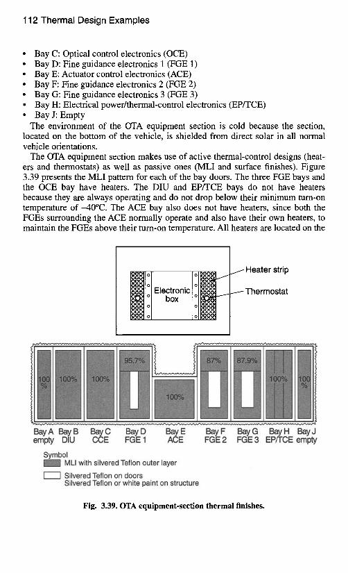
112 Thermal Design Examples
• Bay C: Optical control electronics (OCE) • Bay D: Fine guidance electronics 1 (FGE 1) • Bay E: Actuator control electronics (ACE) • Bay F: Fine guidance electronics 2 (FGE 2) • Bay G: Fine guidance electronics 3 (FGE3) • Bay H: Electrical power/thermal-control electronics (EP/TCE) • Bay J: Empty
The environment of the OTA equipment section is cold because the section, located on the bottom of the vehicle, is shielded from direct solar in all normal vehicle orientations.
The OTA equipment section makes use of active thermal-control designs (heat- ers and thermostats) as well as passive ones (MLI and surface finishes). Figure 3.39 presents the MLI pattern for each of the bay doors. The three FGE bays and the OCE bay have heaters. The DIU and EP/TCE bays do not have heaters because they are always operating and do not drop below their minimum turn-on temperature of -40°C. The ACE bay also does not have heaters, since both the FGEs surrounding the ACE normally operate and also have their own heaters, to maintain the FGEs above their turn-on temperature. All heaters are located on the
Heater strip
Electronic Thermostat box
Bay A Bay B Bay C Bay D Batty E Bay F Bay G Bay H Bay J empty DIU CCE FGE 1 ACE FGE 2 FGE 3 EP/TCE empty
Symbol MLI with silvered Teflon outer layer
Silvered Teflon on doors Silvered Teflon or white paint on structure
Fig. 3.39. OTA equipment-section thermal finishes.
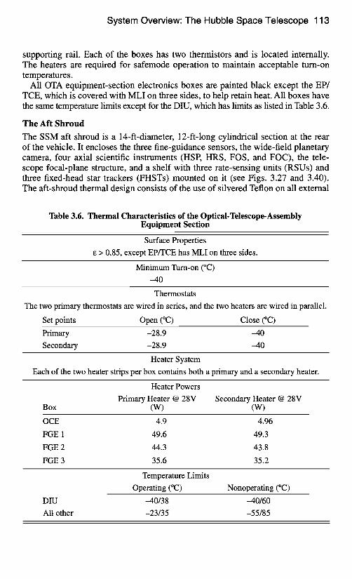
System Overview: The Hubble Space Telescope 113
supporting rail. Each of the boxes has two thermistors and is located internally. The heaters are required for safemode operation to maintain acceptable turn-on temperatures.
All OTA equipment-section electronics boxes are painted black except the EP/ TCE, which is covered with MLI on three sides, to help retain heat. All boxes have the same temperature limits except for the DIU, which has limits as listed in Table 3.6.
The Aft Shroud
The SSM aft shroud is a 14-ft-diameter, 12-ft-long cylindrical section at the rear of the vehicle. It encloses the three fine-guidance sensors, the wide-field planetary camera, four axial scientific instruments (HSP, HRS, FOS, and FOC), the tele- scope focal-plane structure, and a shelf with three rate-sensing units (RSUs) and three fixed-head star trackers (FHSTs) mounted on it (see Figs. 3.27 and 3.40). The aft-shroud thermal design consists of the use of silvered Teflon on all external
Table 3.6. Thermal Characteristics of the Optical-Telescope-Assembly Equipment Section
Surface Properties
e > 0.85, except EPffCE has MLI on three sides.
Minimum Turn-on (°C)
-40
Thermostats
The two primary thermostats are wired in series, and the two heaters are wired in parallel.
Set points Open (°C) Close (°C)
Primary -28.9 -40
Secondary -28.9 -40
Heater System
Each of the two heater strips per box contains both a primary and a secondary heater.
Heater Powers
Primary Heater @ 28V Secondary Heater @ 28V Box (W) (W)
OCE 4.9 4.96
FGE 1 49.6 49.3
FGE 2 44.3 43.8
FGE 3 35.6 35.2
Temperature Limits
Operating (°C) Nonoperating (°C)
DIU -40/38 -40/60
All other -23/35 -55/85
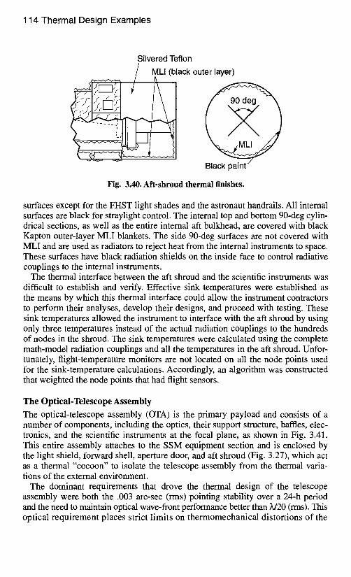
Silvered Teflon lack outer layer)
114 Thermal Design Examples
Fig. 3.40. Aft-shroud thermal finishes.
surfaces except for the FHST light shades and the astronaut handrails. All internal surfaces are black for straylight control. The internal top and bottom 90-deg cylin- drical sections, as well as the entire intemal aft bulkhead, are covered with black Kapton outer-layer MLI blankets. The side 90-deg surfaces are not covered with MLI and are used as radiators to reject heat from the internal instruments to space. These surfaces have black radiation shields on the inside face to control radiative couplings to the intemal instruments.
The thermal interface between the aft shroud and the scientific instruments was difficult to establish and verify. Effective sink temperatures were established as the means by which this thermal interface could allow the instrument contractors to perform their analyses, develop their designs, and proceed with testing. These sink temperatures allowed the instrument to interface with the aft shroud by using only three temperatures instead of the actual radiation couplings to the hundreds of nodes in the shroud. The sink temperatures were calculated using the complete math-model radiation couplings and all the temperatures in the aft shroud. Unfor- tunately, flight-temperature monitors are not located on all the node points used for the sink-temperature calculations. Accordingly, an algorithm was constructed that weighted the node points that had flight sensors.
The Optical-Telescope Assembly
The optical-telescope assembly (OTA) is the primary payload and consists of a number of components, including the optics, their support structure, baffles, elec- tronics, and the scientific instruments at the focal plane, as shown in Fig. 3.41. This entire assembly attaches to the SSM equipment section and is enclosed by the light shield, forward shell, aperture door, and aft shroud (Fig. 3.27), which act as a thermal "cocoon" to isolate the telescope assembly from the thermal varia- tions of the external environment.
The dominant requirements that drove the thermal design of the telescope assembly were both the .003 arc-sec (rms) pointing stability over a 24-h period and the need to maintain optical wave-front performance better than )d20 (rms). This optical requirement places strict limits on thermomechanical distortions of the
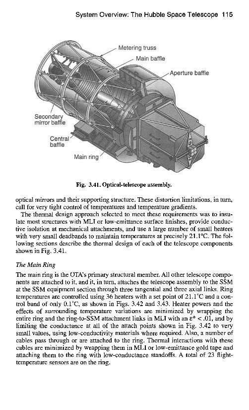
System Overview: The Hubble Space Telescope 115
Metering truss
.... -1 baffle
'~:~':~ rture baffle
mirror baffle
Central" baffle
Main ring
Fig. 3.41. Optical-telescope assembly.
optical mirrors and their supporting structure. These distortion limitations, in tum, call for very tight control of temperatures and temperature gradients.
The thermal design approach selected to meet these requirements was to insu- late most structures with MLI or low-emittance surface finishes, provide conduc- tive isolation at mechanical attachments, and use a large number of small heaters with very small deadbands to maintain temperatures at precisely 21.1°C. The fol- lowing sections describe the thermal design of each of the telescope components shown in Fig. 3.41.
The Main Ring
The main ring is the OTA's primary structural member. All other telescope compo- nents are attached to it, and it, in turn, attaches the telescope assembly to the SSM at the SSM equipment section through three tangential and three axial links. Ring temperatures are controlled using 36 heaters with a set point of 21.1°C and a con- trol band of only 0.1"C, as shown in Figs. 3.42 and 3.43. Heater powers and the effects of surrounding temperature variations are minimized by wrapping the entire ring and the ring-to-SSM attachment links in MLI with an E* < .01, and by limiting the conductance at all of the attach points shown in Fig. 3.42 to very small values, using low-conductivity materials where required. Also, a number of cables pass through or are attached to the ring. Thermal interactions with these cables are minimized by wrapping them in MLI or low-emittance gold tape and attaching them to the ring with low-conductance standoffs. A total of 23 flight- temperature sensors are on the ring.
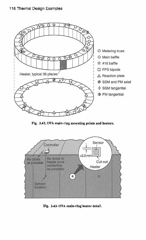
116 Thermal Design Examples
O Metering truss
O Main baffle
"~r #16 baffle
D FPS bipods
/k Reaction plate
• SSM and PM axial
0 SSM tangential
~ PM tangential
Fig. 3.42. OTA main-ring mounting points and heaters.
Fig. 3.43. OTA main-ring heater detail.
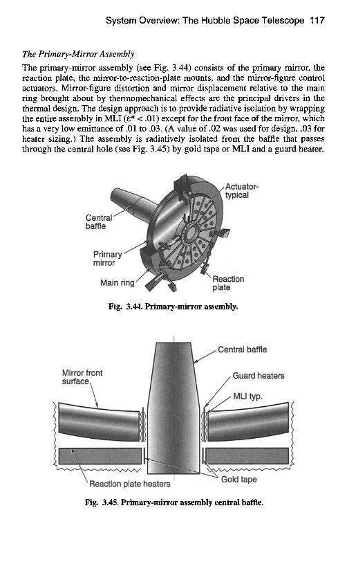
System Overview: The Hubble Space Telescope 117
The Primary-Mirror Assembly
The primary-mirror assembly (see Fig. 3.44) consists of the primary mirror, the reaction plate, the mirror-to-reaction-plate mounts, and the mirror-figure control actuators. Mirror-figure distortion and mirror displacement relative to the main ring brought about by thermomechanical effects are the principal drivers in the thermal design. The design approach is to provide radiative isolation by wrapping the entire assembly in MLI (e* < .01) except for the front face of the mirror, which has a very low emittance of .01 to .03. (A value of .02 was used for design, .03 for heater sizing.) The assembly is radiatively isolated from the baffle that passes through the central hole (see Fig. 3.45) by gold tape or MLI and a guard heater.
/ Actuator- . i ~ ) typical
Centra baffle
Primary mirror
Main rinn / ~ Reaction "'~ ~¢" ' I plate
Fig. 3.44. Primary-mirror assembly.
Central baffle
Mirror front sufface~ Guard h.eaters
/ 'i
~ heaters I
Fig. 3.45. Primary-mirror assembly central baffle.
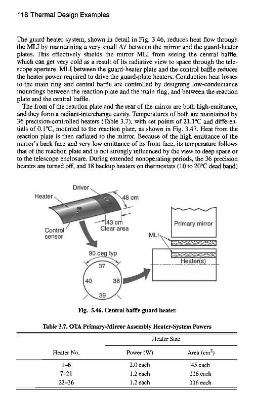
118 Thermal Design Examples
The guard heater system, shown in detail in Fig. 3.46, reduces heat flow through the MLI by maintaining a very small AT between the mirror and the guard-heater plates. This effectively shields the mirror MLI from seeing the central baffle, which can get very cold as a result of its radiative view to space through the tele- scope aperture. MLI between the guard-heater plate and the control baffle reduces the heater power required to drive the guard-plate heaters. Conduction heat losses to the main ring and central baffle are controlled by designing low-conductance mountings between thereaction plate and the main ring, and between the reaction plate and the central baffle.
The front of the reaction plate and the rear of the mirror are both high-emittance, and they form a radiant-interchange cavity. Temperatures of both are maintained by 36 precision-controlled heaters (Table 3.7), with set points of 21.1°C and differen- tials of 0.1°C, mounted to the reaction plate, as shown in Fig. 3.47. Heat from the reaction plate is then radiated to the mirror. Because of the high emittance of the mirror's back face and very low emittance of its front face, its temperature follows that of the reaction plate and is not strongly influenced by the view to deep space or to the telescope enclosure. During extended nonoperating periods, the 36 precision heaters are turned off, and 18 backup heaters on thermostats (10 to 20°C dead band)
Driver
H e a t e ~ ~ ~ : m ..... ~:;ii;iiZS
Control sensor
Primary mirror ML,
H_eater(s)__
Fig. 3.46. Central baffle guard heater.
Table 3.7. OTA Primary-Mirror Assembly Heater-System Powers
Heater Size
Heater No. Power (W) Area (cm 2)
1--6 2.0 each 45 each
7-21 1.2 each 116 each
22-36 1.2 each 116 each
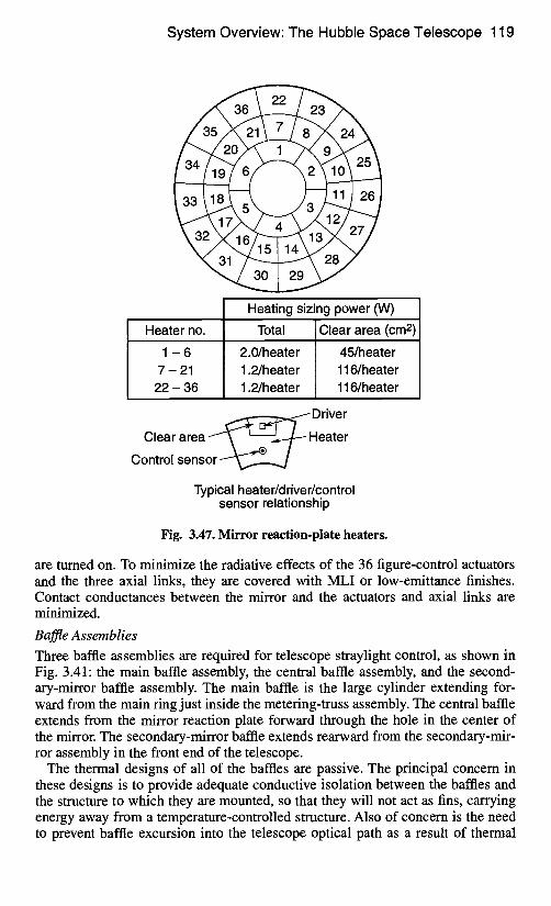
System Overview: The Hubble Space Telescope 119
Heating sizing power (W)
Heater no.
1 - 6 7-21
22- 36
Total
2.0/heater 1.2/heater 1.2/heater
Clear area (cm 2)
45/heater 116/heate r 116/heate r
~~--u--u--u--u--u--~~ Driver
Clear area - ' ~ ~ . . ~ H e a t e r
Control sensor
Typical heater/driver/control sensor relationship
Fig. 3.47. Mirror reaction-plate heaters.
are turned on. To minimize the radiative effects of the 36 figure-control actuators and the three axial links, they are covered with MLI or low-emittance finishes. Contact conductances between the mirror and the actuators and axial links are minimized.
Baffle Assemblies Three baffle assemblies are required for telescope straylight control, as shown in Fig. 3.41: the main baffle assembly, the central baffle assembly, and the second- ary-mirror baffle assembly. The main baffle is the large cylinder extending for- ward from the main ring just inside the metering-truss assembly. The central baffle extends from the mirror reaction plate forward through the hole in the center of the mirror. The secondary-mirror baffle extends rearward from the secondary-mir- ror assembly in the front end of the telescope.
The thermal designs of all of the baffles are passive. The principal concern in these designs is to provide adequate conductive isolation between the baffles and the structure to which they are mounted, so that they will not act as fins, carrying energy away from a temperature-controlled structure. Also of concern is the need to prevent baffle excursion into the telescope optical path as a result of thermal
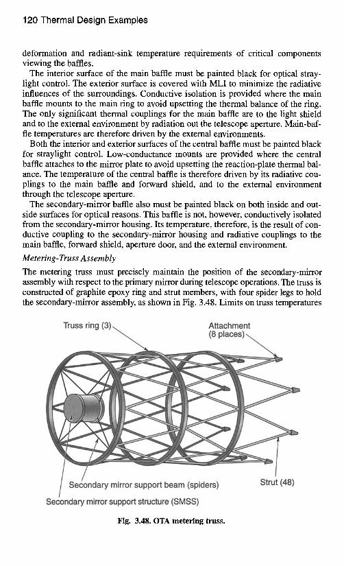
120 Thermal Design Examples
deformation and radiant-sink temperature requirements of critical components viewing the baffles.
The interior surface of the main baffle must be painted black for optical stray- light control. The exterior surface is covered with MLI to minimize the radiative influences of the surroundings. Conductive isolation is provided where the main baffle mounts to the main ring to avoid upsetting the thermal balance of the ring. The only significant thermal couplings for the main baffle are to the light shield and to the external environment by radiation out the telescope aperture. Main-baf- fle temperatures are therefore driven by the external environments.
Both the interior and exterior surfaces of the central baffle must be painted black for straylight control. Low-conductance mounts are provided where the central baffle attaches to the mirror plate to avoid upsetting the reaction-plate thermal bal- ance. The temperature of the central baffle is therefore driven by its radiative cou- plings to the main baffle and forward shield, and to the external environment through the telescope aperture.
The secondary-mirror baffle also must be painted black on both inside and out- side surfaces for optical reasons. This baffle is not, however, conductively isolated from the secondary-mirror housing. Its temperature, therefore, is the result of con- ductive coupling to the secondary-mirror housing and radiative couplings to the main baffle, forward shield, aperture door, and the external environment.
Metering- Truss Assembly
The metering truss must precisely maintain the position of the secondary-mirror assembly with respect to the primary mirror during telescope operations. The truss is constructed of graphite epoxy ring and strut members, with four spider legs to hold the secondary-mirror assembly, as shown in Fig. 3.48. Limits on truss temperatures
Truss ring (3) Attachment
Secondary mirror support beam (spiders)
Secondary mirror support structure (SMSS)
Strut (48)
Fig. 3.48. OTA metering truss.
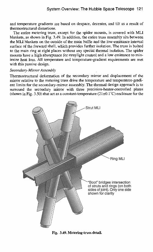
System Overview: The Hubble Space Telescope 121
and temperature gradients are based on despace, decenter, and tilt as a result of thermostructural distortions.
The entire metering truss, except for the spider mounts, is covered with MLI blankets, as shown in Fig. 3.49. In addition, the entire truss assembly sits between the MLI blankets on the outside of the main baffle and the low-emittance internal surface of the forward shell, which provides further isolation. The truss is bolted to the main ring at eight places without any special thermal isolation. The spider mounts have a high absorptance for straylight control and a low emittance to min- imize heat loss. All temperature and temperature-gradient requirements are met with this passive design.
Secondary-Mirror Assembly Thermostructural deformation of the secondary mirror and displacement of the mirror relative to the metering truss drive the temperature and temperature-gradi- ent limits for the secondary-mirror assembly. The thermal design approach is to surround the secondary mirror with three precision-heater-controlled plates (shown in Fig. 3.50) that act as a constant-temperature (2 I+_0.1°C) enclosure for the
Strut MLI
Ring MLI
"Boot" bridges intersection of struts and rings (on both sides of joint). Only one side shown for clarity
Fig. 3.49. Metering-truss detail.
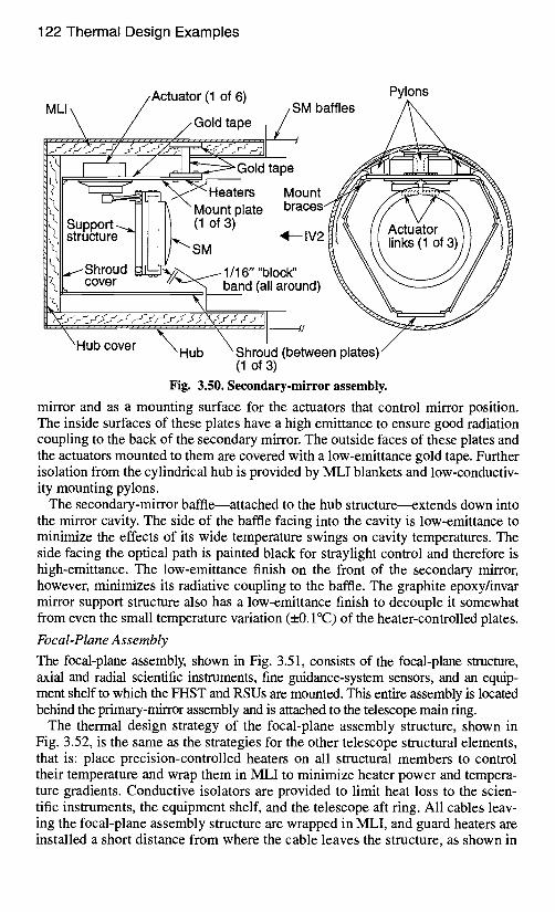
122 Thermal Design Examples
/Actuator (1 of 6) Pylons MLI \ / / SM baffles
..~. / . . . /Gold tape I / i = "
~l I I / ~__~~Gold tape ,# t~'l~ ' ~ ' ~ ~ ~ r s Mount . ~ ~1/ ~'q~l ~" \ Mount plate braces~ff//,~ \~11 Support~_l I I III (1 of 3) /~( ,~llstructure_lll I I ~ s M ,,, ,~-,, IV2~ ~ / ~ll~Shroud tdrL-W~ff~ J 1/16' block' \11~ cover .... ~ band (all around)
~"~H;;" ;;;;;"" "~,'H;;"" '~';;;;!d (be~een plates> (1 of 3)
Fig. 3.50. Secondary-mirror assembly.
mirror and as a mounting surface for the actuators that control mirror position. The inside surfaces of these plates have a high emittance to ensure good radiation coupling to the back of the secondary mirror. The outside faces of these plates and the actuators mounted to them are covered with a low-emittance gold tape. Further isolation from the cylindrical hub is provided by MLI blankets and low-conductiv- ity mounting pylons.
The secondary-mirror baffle--attached to the hub structure---extends down into the mirror cavity. The side of the baffle facing into the cavity is low-emittance to minimize the effects of its wide temperature swings on cavity temperatures. The side facing the optical path is painted black for straylight control and therefore is high-emittance. The low-emittance finish on the front of the secondary mirror, however, minimizes its radiative coupling to the baffle. The graphite epoxy/invar mirror support structure also has a low-emittance finish to decouple it somewhat from even the small temperature variation (_0. I°C) of the heater-controlled plates.
Focal-Plane Assembly The focal-plane assembly, shown in Fig. 3.51, consists of the focal-plane structure, axial and radial scientific instruments, fine guidance-system sensors, and an equip- ment shelf to which the FHST and RSUs are mounted. This entire assembly is located behind the primary-mirror assembly and is attached to the telescope main ring.
The thermal design strategy of the focal-plane assembly structure, shown in Fig. 3.52, is the same as the strategies for the other telescope structural elements, that is" place precision-controlled heaters on all structural members to control their temperature and wrap them in MLI to minimize heater power and tempera- ture gradients. Conductive isolators are provided to limit heat loss to the scien- tific instruments, the equipment shelf, and the telescope aft ring. All cables leav- ing the focal-plane assembly structure are wrapped in MLI, and guard heaters are installed a short distance from where the cable leaves the structure, as shown in
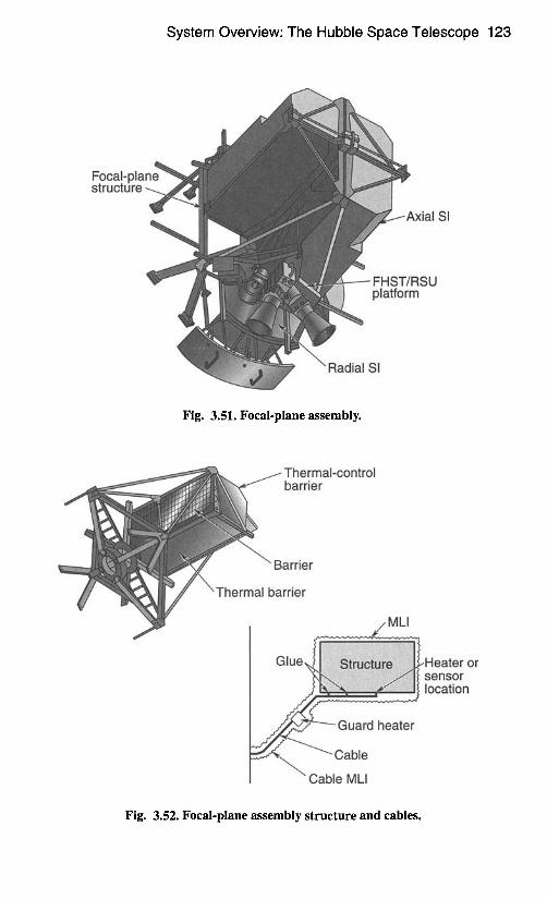
System Overview: The Hubble Space Telescope 123
Focal-plane structu re
SI
FHST/RSU platform
\ Radial SI
Fig. 3.51. Focal-plane assembly.
~ Thermal-control , ~ barrier
"Barrier
Thermal barrier
o r
Fig. 3.52. Focal-plane assembly structure and cables.
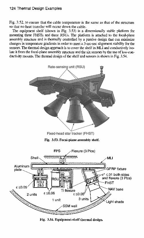
124 Thermal Design Examples
Fig. 3.52, to ensure that the cable temperature is the same as that of the structure so that no heat transfer will occur down the cable.
The equipment shelf (shown in Fig. 3.53) is a dimensionally stable platform for mounting three FHSTs and three RSUs. The platform is attached to the focal-plane assembly structure and is thermally controlled by a passive design that can minimlz" e changes in temperature gradients in order to meet a 3-arc-sec alignment stability for the sensors. The thermal design approach is to cover the shelf in MLI and conductively iso- late it from the focal-plane assembly structure and the six sensors by the use of low-con- ductivity mounts. The thermal design of the shelf and sensors is shown in Fig. 3.54.
Rate-sensing unit (RSU)
Fixed-head star tracker (FHST)
Fig. 3.53. Focal-plane assembly shelf.
FPS .././Flexure (3 Pies) / / / / / / / / / / / / / / . ~ / / / / / / /
MLI
Aluminum ltl I(} plate ~ ~ ~ - ~ U - c , - - z - - - ~ ~ ~ G F R P fixture
~ ~ ~ ~ ' ~ ~ i l t \ ~ " ~ - ~ ~ * <.01 both sides [RSUI~ [ ~ ~ / ~ and flexure (3 Pies)
xs <0.0S" ~ - " " ' ~ ~ , , ~ , L ~ , , . . fA_ . . I "~ ~ NAV base
Fig. 3.54. Equipment-shelf thermal design.
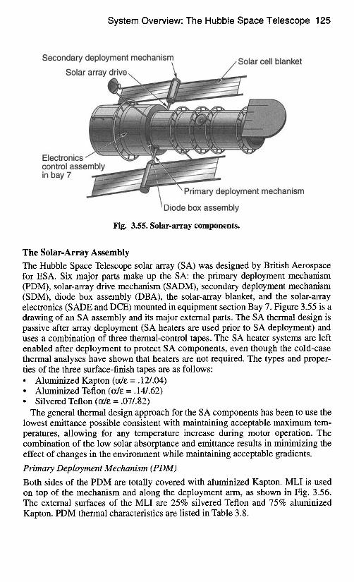
System Overview: The Hubble Space Telescope 125
Secondary deployment mechanism \
Solar array drive \ Solar cell blanket
Electronics / ' " control assembly in bay 7
" Primary deployment mechanism
Diode box assembly
Fig. 3.55. Solar-array components.
The Solar-Array Assembly The Hubble Space Telescope solar array (SA) was designed by British Aerospace for ESA. Six major parts make up the SA: the primary deployment mechanism (PDM), solar-array drive mechanism (SADM), secondary deployment mechanism (SDM), diode box assembly (DBA), the solar-array blanket, and the solar-array electronics (SADE and DCE) mounted in equipment section Bay 7. Figure 3.55 is a drawing of an SA assembly and its major external parts. The SA thermal design is passive after array deployment (SA heaters are used prior to SA deployment) and uses a combination of three thermal-control tapes. The SA heater systems are left enabled after deployment to protect SA components, even though the cold-case thermal analyses have shown that heaters are not required. The types and proper- ties of the three surface-finish tapes are as follows: • Aluminized Kapton (~E =.12/.04) • Aluminized Teflon (~E = .14/.62) • Silvered Teflon (ode = .07/.82)
The general thermal design approach for the SA components has been to use the lowest emittance possible consistent with maintaining acceptable maximum tem- peratures, allowing for any temperature increase during motor operation. The combination of the low solar absorptance and emittance results in minimizing the effect of changes in the environment while maintaining acceptable gradients.
Primary Deployment Mechanism (PDM)
Both sides of the PDM are totally covered with aluminized Kapton. MLI is used on top of the mechanism and along the deployment arm, as shown in Fig. 3.56. The external surfaces of the MLI are 25% silvered Teflon and 75% aluminized Kapton. PDM thermal characteristics are listed in Table 3.8.
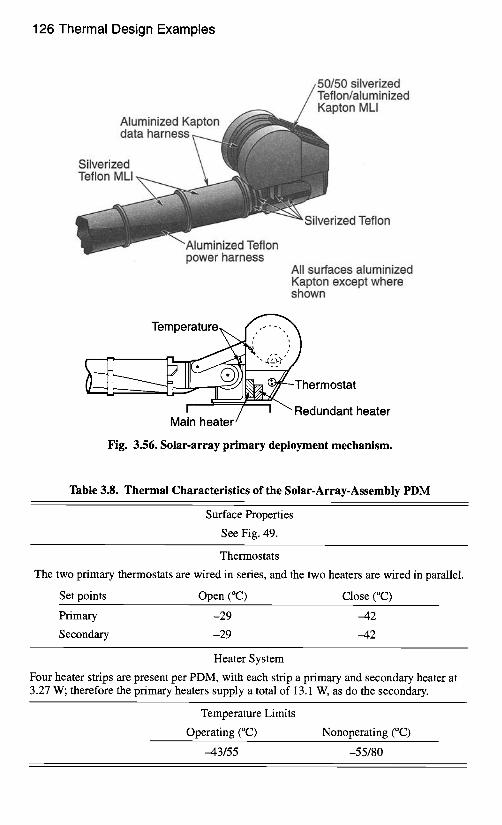
126 Thermal Design Examples
Aluminized Kapton data harness ,..._
Silverized Teflon MLI
50/50 silverized
Kapton MLI
Silverized Teflon
Aluminized Teflon power harness
All surfaces aluminized Kapton except where shown
- Malin ho~ater / ' \ Fledundant heater
Fig. 3.56. Solar-array primary deployment mechanism.
Table 3.8. Thermal Characteristics of the Solar-Array-Assembly PDM
Surface Properties
See Fig. 49.
Thermostats
The two primary thermostats are wired in series, and the two heaters are wired in parallel.
Set points Open (°C) Close (°C)
Primary -29 -42
Secondary -29 -42
Heater System
Four heater strips are present per PDM, with each strip a primary and secondary heater at 3.27 W; therefore the primary heaters supply a total of 13.1 W, as do the secondary.
Temperature Limits
Operating (°C) Nonoperating (°C)
-43/55 -55/80
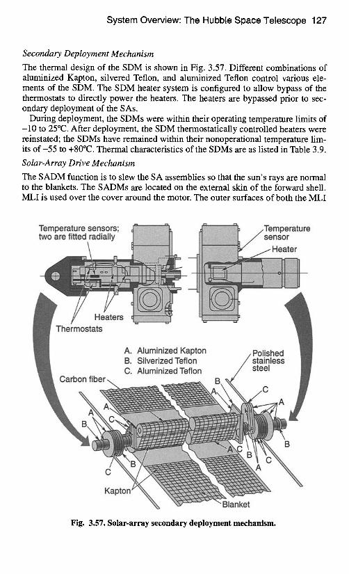
System Overview: The Hubble Space Telescope 127
Secondary Deployment Mechanism
The thermal design of the SDM is shown in Fig. 3.57. Different combinations of aluminized Kapton, silvered Teflon, and aluminized Teflon control various ele- ments of the SDM. The SDM heater system is configured to allow bypass of the thermostats to directly power the heaters. The heaters are bypassed prior to sec- ondary deployment of the SAs.
During deployment, the SDMs were within their operating temperature limits of -10 to 25°C. After deployment, the SDM thermostatically controlled heaters were reinstated; the SDMs have remained within their nonoperational temperature lim- its o f -55 to +80°C. Thermal characteristics of the SDMs are as listed in Table 3.9.
Solar-Array Drive Mechanism
The SADM function is to slew the SA assemblies so that the sun's rays are normal to the blankets. The SADMs are located on the external skin of the forward shell. MLI is used over the cover around the motor. The outer surfaces of both the MLI
Temperature sensors; two are fitted radially ~lliillillitili!iililli~k Tesensormperature
JHeater
// Heaters Thermostats
Carbon fiber
A. Aluminized Kapton B. Silverized Teflon C. Aluminized Teflon
Polished stainless I ! steel !
./
Kapton ~
Blanket
Fig. 3.57. Solar-array secondary deployment mechanism.
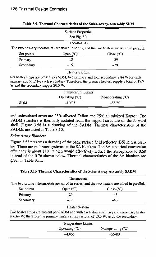
128 Thermal Design Examples
Table 3.9. Thermal Characteristics of the Solar-Array-Assembly SDM
Surface Properties See Fig. 50.
Thermostats The two primary thermostats are wired in series, and the two heaters are wired in parallel.
Set points Open (°C) Close (°C)
Primary -15 -29
Secondary -15 -29
Heater System Six heater strips are present per SDM, two primary and four secondary, 8.84 W for each primary and 5.12 for each secondary. Therefore, the primary heaters supply a total of 17.7 W and the secondary supply 20.5 W.
Temperature Limits Operating (°C) Nonoperating (°C)
SDM -10/25 -55/80
and uninsulated areas are 25% silvered Teflon and 75% aluminized Kapton. The SADM structure is thermally isolated from the support structure on the forward shell. Figure 3.58 is a drawing of the SADM. Thermal characteristics of the SADMs are listed in Table 3.10.
Solar-Array Blankets
Figure 3.58 presents a drawing of the back surface field reflector (BSFR) SA blan- ket. There are no heater systems on the SA blankets. The SA electrical-conversion efficiency is about 11%, which would effectively reduce the absorptance to 0.68 instead of the 0.76 shown below. Thermal characteristics of the SA blankets are given in Table 3.11.
Table 3.10. Thermal Characteristics of the Solar-Array-Assembly SADM
Thermostats The two primary thermostats are wired in series, and the two heaters are wired in parallel.
Set points Open (°C) Close (°C)
Primary -29 -43
Secondary -29 -43
Heater System Two heater strips are present per SADM and with each strip a primary and secondary heater at 6.64 W; therefore the primary heaters supply a total of 13.3 W, as do the secondary.
Temperature Limits Operating (°C) Nonoperating (°C)
-43/55 -55/80
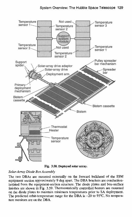
System Overview: The Hubble Space Telescope 129
Tempera I Not used sensor 1 ~Temperature[
Tempera1 sensor 3
I Temp eraturef [i I sensor 2 [
Support spider Solar-array drive adaptor
~ Solar-array drive
Primary deployment mechanism
Bistem cassette
Bistem
/Temperature sensor 3
jTemperature sensor 1
13, ,11^ . . ^ , , , , . . ^^ . . 1^~ .
I
Thermostat ~eater
Temperature sensor
Fig. 3.58. Deployed solar array.
Solar-Array Diode Box Assembly The two DBAs are mounted externally on the forward bulkhead of the SSM equipment section approximately 9 deg apart. The DBA brackets are conduction- isolated from the equipment-section structure. The diode plates and box-surface finishes are shown in Fig. 3.59. Thermostatically controlled heaters are mounted on the diode plates to maintain minimum temperatures prior to SA deployment. The predicted orbit-temperature range for the DBA is -20 to 93°C. No tempera- ture monitors are on the DBA.
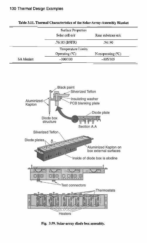
130 Thermal Design Examples
Table 3.11. Thermal Characteristics of the Solar-Array-Assembly Blanket
Surface Properties Solar cell ct/e Rear substrate o~/e
.76/.83 (BSFR) .54/.90
Temperature Limits Operating (°C) Nonoperating (°C)
SA blanket -100/100 -105/105
Black paint ~ ~ Silverized Teflon
,,,.._,_._..., Insulating washer ~a;~on"~u ~ t i [ ~ ~ PCB blanking plate
i " //-Diode plate Diode box structure ~ P " ~ ~ ":" "
Section A.A Silverized Teflon ~
~ ................ .,,.,. ':::~:~E~I w ~ Diode plates
Aluminized Kapton on box external surfaces
Inside of diode box is alodine
m. ~ ::::::::::::::::::::::::::::::::::::::::::::::::::::::::::::::::::::::::::::::::::::::::::::::::::::::::::::::::::::::::::::::::::::::::::::::::::::::::::::::::::::::::::::::::::::::::::::::::::::::::::::::::::::::::::: ~ .~.
' ~ ~ ' - ' ~ ~ T e s t connectors Thermostats
Heaters
Fig. 3.59. Solar-array diode box assembly.
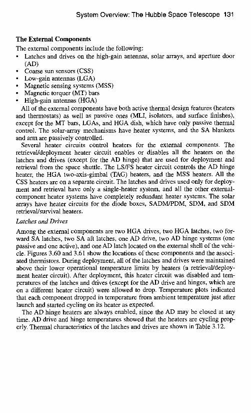
System Overview: The Hubble Space Telescope 131
The External C o m p o n e n t s
The external components include the following: • Latches and drives on the high-gain antennas, solar arrays, and aperture door
(AD) • Coarse sun sensors (CSS) • Low-gain antennas (LGA) • Magnetic sensing systems (MSS) • Magnetic torquer (MT) bars • High-gain antennas (HGA)
All of the external components have both active thermal design features (heaters and thermostats) as well as passive ones (MLI, isolators, and surface finishes), except for the MT bars, LGAs, and HGA dish, which have only passive thermal control. The solar-array mechanisms have heater systems, and the SA blankets and arm are passively controlled.
Several heater circuits control heaters for the external components. The retrieval/deployment heater circuit enables or disables all the heaters on the latches and drives (except for the AD hinge) that are used for deployment and retrieval from the space shuttle. The LS/FS heater circuit controls the AD hinge heater, the HGA two-axis-gimbal (TAG) heaters, and the MSS heaters. All the CSS heaters are on a separate circuit. The latches and drives used only for deploy- ment and retrieval have only a single-heater system, and all the other external- component heater systems have completely redundant heater systems. The solar arrays have heater circuits for the diode boxes, SADM/PDM, SDM, and SDM retrieval/survival heaters.
Latches and Drives
Among the extemal components are two HGA drives, two HGA latches, two for- ward SA latches, two SA aft latches, one AD drive, two AD hinge systems (one passive and one active), and one AD latch located on the external shell of the vehi- cle. Figures 3.60 and 3.61 show the locations of these components and the associ- ated thermistors. During deployment, all of the latches and drives were maintained above their lower operational temperature limits by heaters (a retrieval/deploy- ment heater circuit). After deployment, this heater circuit was disabled and tem- peratures of the latches and drives (except for the AD drive and hinges, which are on a different heater circuit) were allowed to drop. Temperature plots indicated that each component dropped in temperature from ambient temperature just after launch and started cycling on its heater as expected.
The AD hinge heaters are always enabled, since the AD may be closed at any time. AD drive and hinge temperatures showed that the heaters are cycling prop- erly. Thermal characteristics of the latches and drives are shown in Table 3.12.
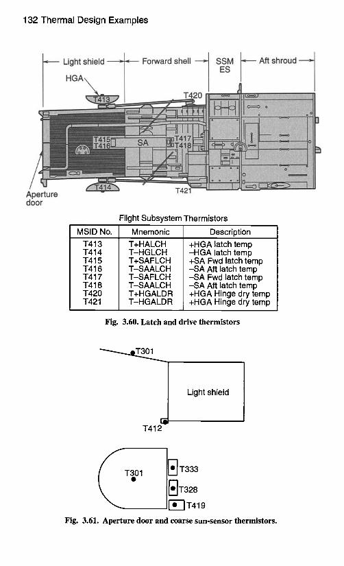
132 Thermal Design Examples
Light shield
Aperture door
HGA\ m
Forward shell ~ SES~VI
+++++L..++++++++ ....... ++"t++:!+ + ++++++++++ + ++ N
Aft shroud =
NiIli+iil~?Nii+~IIN~!~iiii{i++iI+INii~H
~+++++®+++++!~
Flight Subsystem Thermistors
MSID No. Mnemonic Description T413 T414 T415 T416 T417 T418 T420 T421
T+HALCH T-HGLCH T+SAFLCH T-SAALCH T-SAFLCH T-SAALCH T+HGALDR T-HGALDR
+HGA latch temp -HGA latch temp +SA Fwd latch temp -SA Aft latch temp -SA Fwd latch temp -SA Aft latch temp +HGA Hinge dry temp +HGA Hinge dry temp
Fig. 3.60. Latch and drive thermistors
" ~ T 3 0 1 ~ . ~
T412
Light shield
]r• T333
1~'-~T419
Fig. 3.61. Aperture door and coarse sun-sensor thermistors.
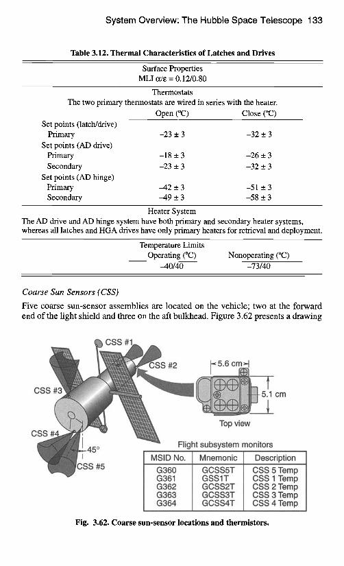
System Overview: The Hubble Space Telescope 133
Table 3.12. Thermal Characteristics of Latches and Drives
Surface Properties MLI ode = 0.12/0.80
Thermostats The two primary thermostats are wired in series with the heater.
Open (°C) Close (°(2) Set points (latch/drive)
Primary -23 _+ 3 -32 _+ 3 Set points (AD drive)
Primary -18 _+ 3 -26 _+ 3
Secondary -23 _+ 3 -32 + 3 Set points (AD hinge)
Primary -42 _+ 3 -51 + 3 Secondary -49 e 3 -58 e 3
Heater System The AD drive and AD hinge system have both primary and secondary heater systems, whereas all latches and HGA drives have only primary heaters for retrieval and deployment.
Temperature Limits Operating (°C) Nonoperating (°C)
-40/40 -73/40
Coarse Sun Sensors (CSS)
Five coarse sun-sensor assemblies are located on the vehicle; two at the forward end of the light shield and three on the aft bulkhead. Figure 3.62 presents a drawing
CSS #3
CSS
I
C, SS #5
#2 ~ 5.6 cml~ii i
~ N;~ N 5.1 cm
Top view
Flight subsystem monitors
MSID No. G360 G361 G362 G363 G364
Mnemonic GCSS5T GSSIT GCSS2T GCSS3T GCSS4T
Description CSS 5 Temp CSS 1 Temp CSS 2 Temp CSS 3 Temp CSS 4 Temp
Fig. 3.62. Coarse sun-sensor locations and thermistors.
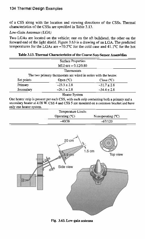
134 Thermal Design Examples
of a CSS along with the location and viewing directions of the CSSs. Thermal characteristics of the CSSs are specified in Table 3.13.
Low-Gain Antennas (LGA)
Two LGAs are located on the vehicle; one on the aft bulkhead, the other on the forward end of the light shield. Figure 3.63 is a drawing of an LGA. The predicted temperatures for the LGAs are -70.5°C for the cold case and 41.1°C for the hot
Table 3.13. Thermal Characteristics of the Coarse Sun-Sensor Assemblies
Surface Properties
MLI (t/e = 0.12/0.80
Thermostats The two primary thermostats are wired in series with the heater.
Set points Open (°C) Close (°C)
Primary -23.3 _ 2.8 -31.7 +_. 2.8 Secondary -26.1 +_ 2.8 -34.4 _ 2.8
Heater System One heater strip is present per each CSS, with each strip containing both a primary and a secondary heater at 4.08 W. CSS 4 and CSS 5 are mounted on a common bracket and have only one heater system.
Temperature Limits Operating (°C) Nonoperating (°C)
-40/38 -67/120
1.5 cm .,, n Top view
Side'
Fig. 3.63. Low-gain antenna
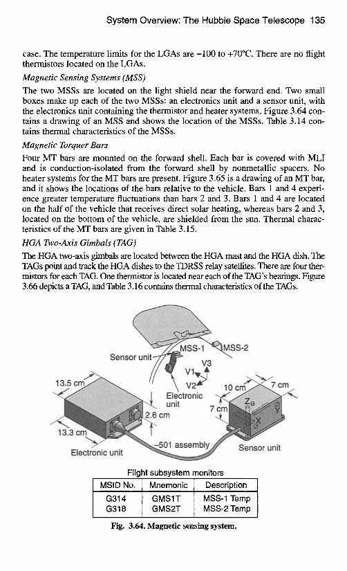
System Overview: The Hubble Space Telescope 135
case. The temperature limits for the LGAs are -100 to +70°C. There are no flight thermistors located on the LGAs.
Magnetic Sensing Systems (MSS) The two MSSs are located on the light shield near the forward end. Two small boxes make up each of the two MSSs: an electronics unit and a sensor unit, with the electronics unit containing the thermistor and heater systems. Figure 3.64 con- tains a drawing of an MSS and shows the location of the MSSs. Table 3.14 con- tains thermal characteristics of the MSSs.
Magnetic Torquer Bars Four MT bars are mounted on the forward shell. Each bar is covered with MLI and is conduction-isolated from the forward shell by nonmetallic spacers. No heater systems for the MT bars are present. Figure 3.65 is a drawing of an MT bar, and it shows the locations of the bars relative to the vehicle. Bars 1 and 4 experi- ence greater temperature fluctuations than bars 2 and 3. Bars 1 and 4 are located on the half of the vehicle that receives direct solar heating, whereas bars 2 and 3, located on the bottom of the vehicle, are shielded from the sun. Thermal charac- teristics of the MT bars are given in Table 3.15.
HGA Two-Axis Gimbals (TAG) The HGA two-axis gimbals are located between the HGA mast and the HGA dish. The TAGs point and track the HGA dishes to the TDRSS relay satellites. There are four ther- mistors for each TAG. One thermistor is located near each of the TAG's bearings. Figure 3.66 depicts a TAG, and Table 3.16 contains thermal characteristics of the TAGs.
S-2 Sensor u n i t ~ ' ~ V3
. ~ // V v~_~ 13 5 c r n ~ // ~' V2 ~>1 f~"'~'~/7 c m \ vz-- l o c m ~ u z
~ " ~ii~i~i ~ii!!~i~ii~ii®ii~i -.., "~' unit Electronic 7 cm
2.6 cm
Electronic unit " ~ . ~ ~,~' " " " . . . . . . . . .
Flight subsystem monitors MSID No. Mnemonic Description
G314 GMS1T MSS-1 Temp G318 GMS2T MSS-2 Temp
Fig. 3.64. Magnetic sensing system.
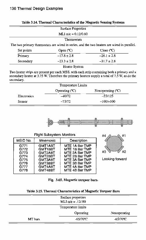
136 Thermal Design Examples
Table 3.14. Thermal Characteristics of the Magnetic Sensing Systems
Surface Properties
MLI tx/e = 0.12/0.80
Thermostats
The two primary thermostats are wired in series, and the two heaters are wired in parallel.
Set points Open (°C) Close (°C)
Primary -17.8 _+ 2.8 -26.1 __. 2.8
Secondary -23.3 _+ 2.8 -31.7 _ 2.8
Heater System
Two heater strips are present per each MSS, with each strip containing both a primary and a secondary heater at 3.75 W. Therefore the primary heaters supply a total of 7.5 W, as do the secondary.
Temperature Limits
Operating (°C) Nonoperating (°C)
Electronics --40/72 -55/125
Sensor -73/72 -100/+ 100
MSID No.
G771 G772 G773 G774 G775 G776 G777 G778
Flight Subsystem Monitors
Mnemonic
GMT1ABT GMT1BBT GMT2ABT GMT2BBT GMT3ABT GMT3BBT GMT4ABT GMT4BBT
Description
MTE 1A Bar TMP MTE 1B Bar TMP MTE 2A Bar TMP MTE 2B Bar TMP MTE 3A Bar TMP MTE 3B Bar TMP MTE 4A Bar TMP MTE 4B Bar TMP
12 Looking forward
Fig. 3.65. Magnetic torquer bars.
Table 3.15. Thermal Characteristics of Magnetic Torquer Bars
Surface properties MLI ~ e = .12/.80
Temperature limits
Operating Nonoperating
MT bars -65/70°C -65/70°C
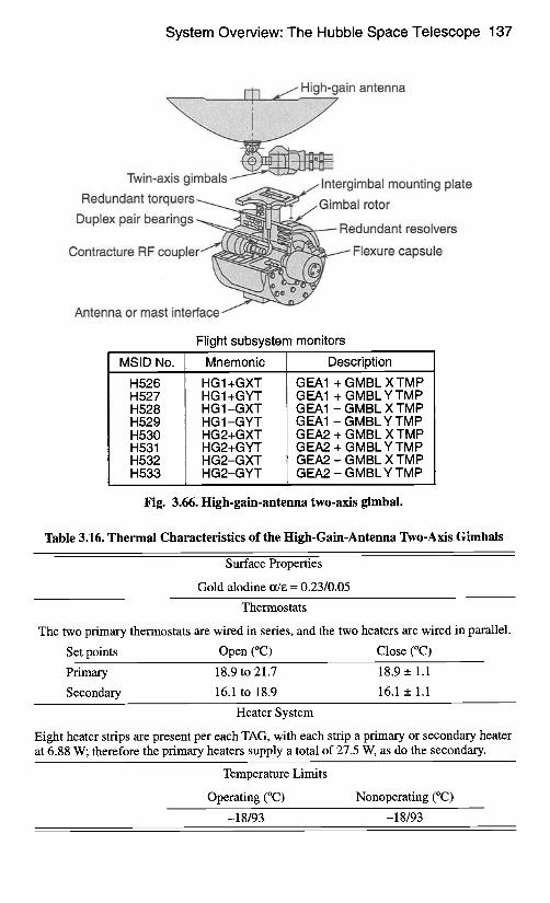
System Overview: The Hubble Space Telescope 137
High-gain antenna
Twin-axis gimbals Intergimbal mounting plate
Redundant torquers Gimbal rotor
Duplex pair bearings .. Redundant resolvers
Contracture RF coupler Flexure capsule
Antenna or mast interface
Flight subsystem monitors
MSID No.
H526 H527 H528 H529 H530 H531 H532 H533
Mnemonic
HGI+GXT HG 1 +GYT HG1-GXT H G 1 -G YT HG2+GXT HG2+GYT HG2-GXT HG2-GYT
Description
GEA1 + GMBL X TMP GEA1 + GMBL Y TMP GEA1 - GMBL X TMP GEA1 - GMBL Y TMP GEA2 + GMBL X TMP GEA2 + GMBL Y TMP GEA2 - GMBL X TMP GEA2 - GMBL Y TMP
Fig. 3.66. High-gain-antenna two-axis gimbal.
Table 3.16. Thermal Characteristics of the High-Gain-Antenna Two-Axis Gimbals
Surface Properties
Gold alodine ct/e = 0.23/0.05
Thermostats
The two primary thermostats are wired in series, and the two heaters are wired in parallel.
Set points Open (°C) Close (°C)
Primary 18.9 to 21.7 18.9 _+ 1.1
Secondary 16.1 to 18.9 16.1 _ 1.1
Heater System
Eight heater strips are present per each TAG, with each strip a primary or secondary heater at 6.88 W; therefore the primary heaters supply a total of 27.5 W, as do the secondary.
Temperature Limits
Operating (°C) Nonoperating (°C)
-18/93 -18/93


![L 19 - Thermodynamics [4] Thermal radiation examples Thermal radiation examples –Greenhouse effect –Ozone layer Change of phase (ice water steam) Change](https://img.pdfslide.net/doc/110x75/56649f1f5503460f94c3764c/l-19-thermodynamics-4-thermal-radiation-examples-thermal-radiation-examples.jpg)