Embed Size (px)
Citation preview
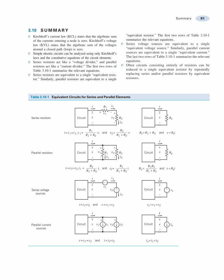
3.10 SUMMARYKirchhoff’s current law (KCL) states that the algebraic sumof the currents entering a node is zero. Kirchhoff’s voltagelaw (KVL) states that the algebraic sum of the voltagesaround a closed path (loop) is zero.Simple electric circuits can be analyzed using only Kirchhoff’slaws and the constitutive equations of the circuit elements.Series resistors act like a “voltage divider,” and parallelresistors act like a “current divider.” The first two rows ofTable 3.10-1 summarize the relevant equations.Series resistors are equivalent to a single “equivalent resis-tor.” Similarly, parallel resistors are equivalent to a single
“equivalent resistor.” The first two rows of Table 3.10-1summarize the relevant equations.Series voltage sources are equivalent to a single“equivalent voltage source.” Similarly, parallel currentsources are equivalent to a single “equivalent current.”The last two rows of Table 3.10-1 summarize the relevantequations.Often circuits consisting entirely of resistors can bereduced to a single equivalent resistor by repeatedlyreplacing series and/or parallel resistors by equivalentresistors.
Table 3.10-1 Equivalent Circuits for Series and Parallel Elements
Circuit
Parallel resistors
Series voltagesources
Parallel currentsources
Series resistors Circuit–
+v
–
+v
v, v
–
– ++
v2
v2
v2
v1
v1
v1
R2
R1
R1 R2
R1 + R2
R2 R1
R1 + R2 R1 + R2
R1
R1 + R2
R1 + R2
R1R2
and
andand
and
and
Rs= R1 + R2
vs= v1+ v2
ip= i1+ i2
Rp=
v = Rsi
v = Rpi
Rs
i1 i
Circuit–
+
–+
v Rp
i
Circuit
–
+
v vs
i
i
Circuit
–
+
v ip
i
i2
R2i2
i2
i1i
i1
i
i
i = i 1= i 2 ,v 1=
v = v1= v2, i1 =
i = i1= i2
i
i = i1+ i2
v = v1+ v2
v1 i1 v2 i2
v = v1= v2
i2=i, i
Circuit
Circuit
Circuit
– – –
+
–
–
+
+
+ +v
–
+v
– – –
+ + +v
and v2=
Summary 91

PROBLEMS
Section 3.2 Kirchhoff’s Laws
P 3.2-1 Consider the circuit shown in Figure P 3.2-1.Determine the values of the power supplied by branch B and thepower supplied by branch F.
+
–
+
–
+
+
+–
–
–+
–
–12 V 12 V 12 V 4 A
4 V
1 A
–1 A
1 A
–5 V
2 A iA B C F
D
E
v
Figure P 3.2-1
P 3.2-2 Determine the values of i2, i4, v2, v3, and v6 in FigureP 3.2-2.
6 V 2 A
+
– +
–
+
–
+
++
–
––
–2 V
6 A
4 V
3 A
–3 Ai2 i4A B D
C E
Fv2
v3
v6
Figure P 3.2-2
P 3.2-3 Consider the circuit shown in Figure P 3.2-3.
(a) Suppose that R1¼ 8 V and R2¼ 4 V. Find the current i andthe voltage v.
(b) Suppose, instead, that i¼ 2.25 A and v¼ 42 V. Determinethe resistances R1 and R2.
(c) Suppose, instead, that the voltage source supplies 24 W ofpower and that the current source supplies 9 W of power.Determine the current i, the voltage v, and the resistancesR1 and R2.
12 V 3 A
+
–
+–
i
R2
R1 v
Figure P 3.2-3
P 3.2-4 Determine the power absorbed by each of the resistorsin the circuit shown in Figure P 3.2-4.
Answer: The 4-V resistor absorbs 100 W, the 6-V resistorabsorbs 24 W, and the 8-V resistor absorbs 72 W.
12 V 20 V
3 A
6 Ω 4 Ω
8 Ω
+–
+–
Figure P 3.2-4
P 3.2-5 Determine the power absorbed by each of theresistors in the circuit shown in Figure P 3.2-5.
Answer: The 4-V resistor absorbs 16 W, the 6-V resistorabsorbs 24 W, and the 8-V resistor absorbs 8 W.
6 V
8 V
8 V
2 A 12 V
6 Ω 8 Ω
4 Ω
+–
+–
+–
+–
Figure P 3.2-5
P 3.2-6 Determine the power supplied by each voltage sourcein the circuit of Figure P 3.2-6.
Answer: The 2-V voltage source supplies 2 mW and the 3-Vvoltage source supplies "6 mW.
3 mA
5 mA
3 V+– +–
2 V
2 mA
Figure P 3.2-6
P 3.2-7 What is the value of the resistance R in FigureP 3.2-7.
Hint: Assume an ideal ammeter. An ideal ammeter isequivalent to a short circuit.
Answer: R¼ 4 V
12 V 2 A
1 A
Ammeter
R
+–
Figure P 3.2-7
Problem available in WileyPLUS at instructor’s discretion.
92 3. Resistive Circuits
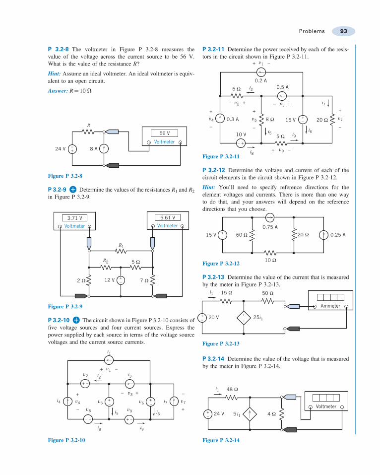
P 3.2-8 The voltmeter in Figure P 3.2-8 measures thevalue of the voltage across the current source to be 56 V.What is the value of the resistance R?
Hint: Assume an ideal voltmeter. An ideal voltmeter is equiv-alent to an open circuit.
Answer: R¼ 10 V
24 V 8 A–+
56 V
Voltmeter
R
Figure P 3.2-8
P 3.2-9 Determine the values of the resistances R1 and R2
in Figure P 3.2-9.
2 Ω 7 Ω
5 Ω
12 V +–
3.71 V
Voltmeter
5.61 V
Voltmeter
R1
R2
Figure P 3.2-9
P 3.2-10 The circuit shown in Figure P 3.2-10 consists offive voltage sources and four current sources. Express thepower supplied by each source in terms of the voltage sourcevoltages and the current source currents.
i4
i1
i2+
++
–
+ –
+ –+
+
–
–+–
–
– +
–
i3
i5 i6
i8 i9
i7v6
v9
v7
v3
v5
v8
v4
v2
v1
Figure P 3.2-10
P 3.2-11 Determine the power received by each of the resis-tors in the circuit shown in Figure P 3.2-11.
6 Ω
8 Ω 20 Ω
5 Ω10 V
15 V0.3 A
+
–
+
–
+
–
+ –
+ –
+–
+–
+–+–
0.2 A0.5 A
i8
i2
i7
i6i9i5
v2 v3
v9
v7v5v4
v1
Figure P 3.2-11
P 3.2-12 Determine the voltage and current of each of thecircuit elements in the circuit shown in Figure P 3.2-12.
Hint: You’ll need to specify reference directions for theelement voltages and currents. There is more than one wayto do that, and your answers will depend on the referencedirections that you choose.
15 V +– 0.25 A
0.75 A60 Ω 20 Ω
10 ΩFigure P 3.2-12
P 3.2-13 Determine the value of the current that is measuredby the meter in Figure P 3.2-13.
P 3.2-14 Determine the value of the voltage that is measuredby the meter in Figure P 3.2-14.
Voltmeter5 i124 V+
–
48 Ω
4 Ω
i1
Figure P 3.2-14
i1
20 V+–
+–
Ammeter
25i1
50 Ω15 Ω
Figure P 3.2-13
Problems 93
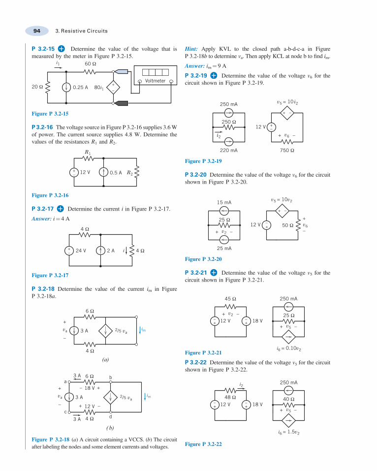
P 3.2-15 Determine the value of the voltage that ismeasured by the meter in Figure P 3.2-15.
Voltmeter+–
80i10.25 A
60 Ω
20 Ω
i1
Figure P 3.2-15
P 3.2-16 The voltage source in Figure P 3.2-16 supplies 3.6 Wof power. The current source supplies 4.8 W. Determine thevalues of the resistances R1 and R2.
12 V 0.5 A
R1
R2+–
Figure P 3.2-16
P 3.2-17 Determine the current i in Figure P 3.2-17.
Answer: i¼ 4 A
2 A24 V+– i 4 Ω
4 Ω
Figure P 3.2-17
P 3.2-18 Determine the value of the current im in FigureP 3.2-18a.
im
im
2/5 va
2/5 va3 A
3 A
(a)
( b)3 A
18 V
12 Vc
ab
d
6 Ω
4 Ω
6 Ω
4 Ω
3 A
+
–
+ +
+–
–
–
va
va
Figure P 3.2-18 (a) A circuit containing a VCCS. (b) The circuitafter labeling the nodes and some element currents and voltages.
Hint: Apply KVL to the closed path a-b-d-c-a in FigureP 3.2-18b to determine va. Then apply KCL at node b to find im.
Answer: im¼ 9 A
P 3.2-19 Determine the value of the voltage v6 for thecircuit shown in Figure P 3.2-19.
250 mA
220 mA
v5 = 10 i2
12 V
750 Ω
250 Ω
+
+
–
–+ –v6i2
Figure P 3.2-19
P 3.2-20 Determine the value of the voltage v6 for the circuitshown in Figure P 3.2-20.
25 mA
12 V+ –
+
–+–
+ –
15 mA
50 Ω25 Ω
v6v2
v5 = 10v2
Figure P 3.2-20
P 3.2-21 Determine the value of the voltage v5 for thecircuit shown in Figure P 3.2-21.
i6 = 0.10v2
12 V 18 V+ –
+ –+–
+–
250 mA
25 Ω
45 Ω
v2
v5
Figure P 3.2-21
P 3.2-22 Determine the value of the voltage v5 for the circuitshown in Figure P 3.2-22.
i6 = 1.5v2
250 mA
18 V+ –
+–
+– 12 V
40 Ω48 Ω
v5
i2
Figure P 3.2-22
94 3. Resistive Circuits

P 3.2-23 Determine the value of the voltage v6 for thecircuit shown in Figure P 3.2-23.
i210i2
12 V12 V 18 V50 Ω
25 Ω v6
+
–
+– +
–
+ –
+–
Figure P 3.2-23
P 3.2-24 Determine the value of the voltage v5 for thecircuit shown in Figure P 3.2-24.
25 mA
250 mA15 mA
+ – + –
0.5v2
25 Ω250 Ω
v5v2
Figure P 3.2-24
P 3.2-25 The voltage source in the circuit shown inFigure P 3.2-25 supplies 2 W of power. The value of thevoltage across the 25-V resistor is v2¼ 4 V. Determinethe values of the resistance R1 and of the gain G of the VCCS.
R1
Gv220 V+
–
+–
25 Ω v2
Figure P 3.2-25
P 3.2-26 Consider the circuit shown in Figure P 3.2-26.Determine the values of
(a) The current ia in the 20-V resistor.(b) The voltage vb across the 10-V resistor.(c) The current ic in the independent voltage source.
ia
ic25 V
+ –+ –
+ –
4 ia
10 Ω20 Ω
vb
Figure P 3.2-26
P 3.2-27 Consider the circuit shown in Figure P 3.2-27.
(a) Determine the values of the resistances.(b) Determine the values of the power supplied by each current
source.(c) Determine the values of the power received by each
resistor.
3 A
+ –
+
–
Rc
RbRa
4 V
−1.5 A12 V
2 A
+ –−3 V
Figure P 3.2-27
P 3.2-28 Consider the circuit shown in Figure P 3.2-28.
(a) Determine the value of the power supplied by eachindependent source.
(b) Determine the value of the power received by eachresistor.
(c) Is power conserved?
3 mA
2 kΩ+ –
12 V
3 kΩ2 mA
18 kΩ
Figure P 3.2-28
P 3.2-29 The voltage across the capacitor in FigureP 3.2-29 is v tð Þ ¼ 24 " 10e"25t V for t ) 0. Determine thevoltage source current i(t) for t > 0.
n(t)i(t)
+
–
+– C 80 Ω
20 Ω30 V
Figure P 3.2-29
P 3.2-30 The current the inductor in Figure P 3.2-30 is givenby i tð Þ ¼ 8 " 6e"25t A for t ) 0. Determine the voltage v(t)across the 80-V resistor for t > 0.
Problems 95
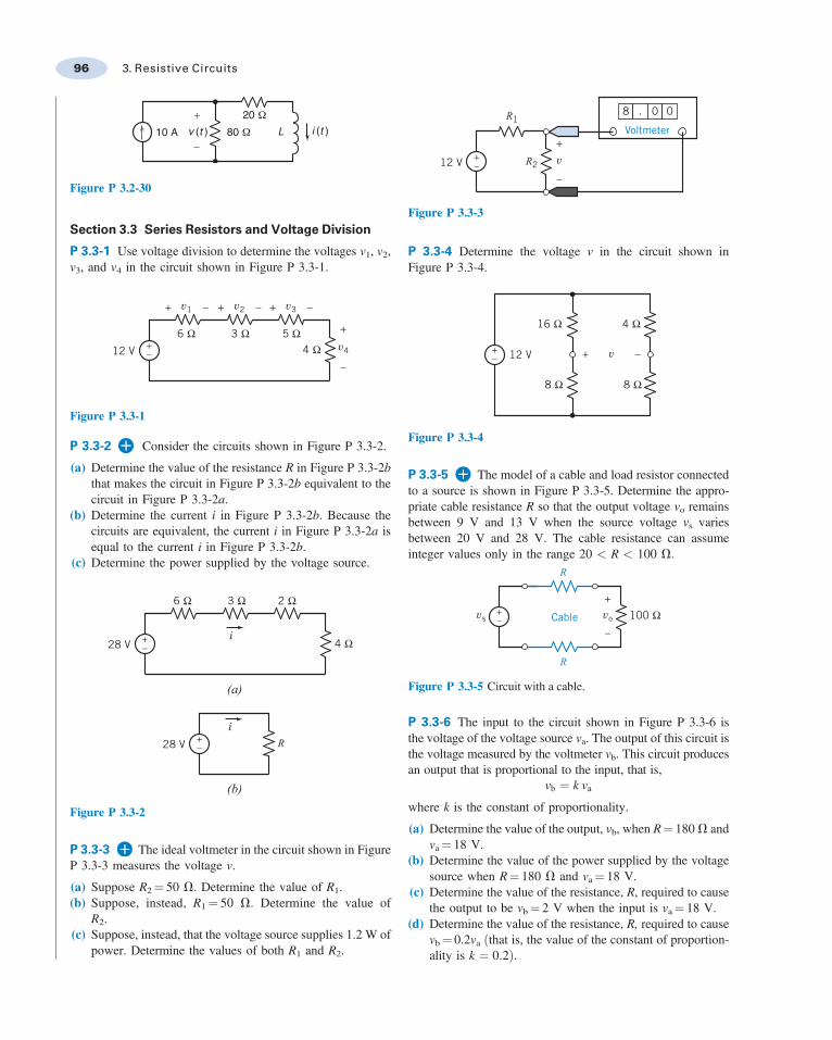
10 A 80 Ω Lv (t )+
–
20 Ωi (t )
Figure P 3.2-30
Section 3.3 Series Resistors and Voltage Division
P 3.3-1 Use voltage division to determine the voltages v1, v2,v3, and v4 in the circuit shown in Figure P 3.3-1.
6 Ω 3 Ω4 Ω
5 Ω+–12 V v4
–
+
v3 –+v2 –+v1 –+
Figure P 3.3-1
P 3.3-2 Consider the circuits shown in Figure P 3.3-2.
(a) Determine the value of the resistance R in Figure P 3.3-2bthat makes the circuit in Figure P 3.3-2b equivalent to thecircuit in Figure P 3.3-2a.
(b) Determine the current i in Figure P 3.3-2b. Because thecircuits are equivalent, the current i in Figure P 3.3-2a isequal to the current i in Figure P 3.3-2b.
(c) Determine the power supplied by the voltage source.
+–28 V
+–28 V
6 Ω 3 Ω 2 Ω
4 Ωi
i
(a)
(b)
R
Figure P 3.3-2
P 3.3-3 The ideal voltmeter in the circuit shown in FigureP 3.3-3 measures the voltage v.
(a) Suppose R2¼ 50 V. Determine the value of R1.(b) Suppose, instead, R1 ¼ 50 V. Determine the value of
R2.(c) Suppose, instead, that the voltage source supplies 1.2 W of
power. Determine the values of both R1 and R2.
v
–
++–12 V
R18
Voltmeter
. 0 0
R2
Figure P 3.3-3
P 3.3-4 Determine the voltage v in the circuit shown inFigure P 3.3-4.
+– 12 V
16 Ω 4 Ω
8 Ω 8 Ω
v –+
Figure P 3.3-4
P 3.3-5 The model of a cable and load resistor connectedto a source is shown in Figure P 3.3-5. Determine the appro-priate cable resistance R so that the output voltage vo remainsbetween 9 V and 13 V when the source voltage vs variesbetween 20 V and 28 V. The cable resistance can assumeinteger values only in the range 20 < R < 100 V.
vovs
R
R
Cable+–
+
–
100 Ω
Figure P 3.3-5 Circuit with a cable.
P 3.3-6 The input to the circuit shown in Figure P 3.3-6 isthe voltage of the voltage source va. The output of this circuit isthe voltage measured by the voltmeter vb. This circuit producesan output that is proportional to the input, that is,
vb ¼ k va
where k is the constant of proportionality.
(a) Determine the value of the output, vb, when R¼ 180 V andva¼ 18 V.
(b) Determine the value of the power supplied by the voltagesource when R¼ 180 V and va¼ 18 V.
(c) Determine the value of the resistance, R, required to causethe output to be vb¼ 2 V when the input is va¼ 18 V.
(d) Determine the value of the resistance, R, required to causevb¼ 0.2va ðthat is, the value of the constant of proportion-ality is k ¼ 0:2Þ.
96 3. Resistive Circuits
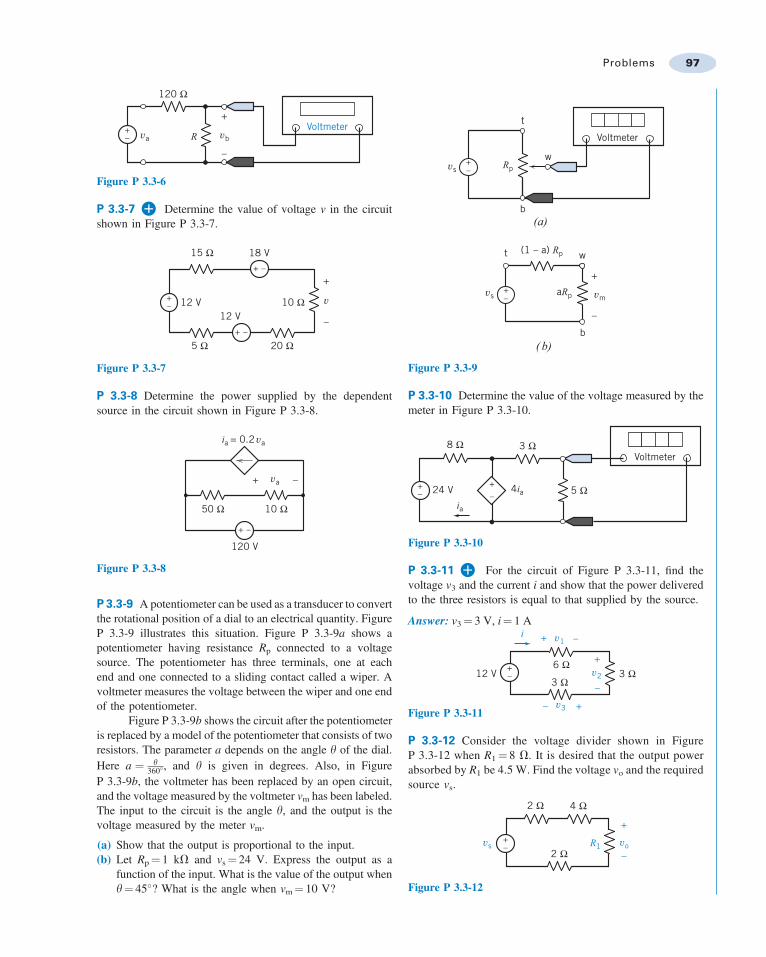
vbva RVoltmeter+
–
+
–
120 Ω
Figure P 3.3-6
P 3.3-7 Determine the value of voltage v in the circuitshown in Figure P 3.3-7.
12 V12 V
18 V
+–
+
–
+ –
+ –
20 Ω5 Ω
15 Ω
10 Ω v
Figure P 3.3-7
P 3.3-8 Determine the power supplied by the dependentsource in the circuit shown in Figure P 3.3-8.
ia = 0.2 va
10 Ω50 Ω
+ –
+ –
120 V
va
Figure P 3.3-8
P 3.3-9 A potentiometer can be used as a transducer to convertthe rotational position of a dial to an electrical quantity. FigureP 3.3-9 illustrates this situation. Figure P 3.3-9a shows apotentiometer having resistance Rp connected to a voltagesource. The potentiometer has three terminals, one at eachend and one connected to a sliding contact called a wiper. Avoltmeter measures the voltage between the wiper and one endof the potentiometer.
Figure P 3.3-9b shows the circuit after the potentiometeris replaced by a model of the potentiometer that consists of tworesistors. The parameter a depends on the angle y of the dial.Here a ¼ y
360', and y is given in degrees. Also, in FigureP 3.3-9b, the voltmeter has been replaced by an open circuit,and the voltage measured by the voltmeter vm has been labeled.The input to the circuit is the angle y, and the output is thevoltage measured by the meter vm.
(a) Show that the output is proportional to the input.(b) Let Rp¼ 1 kV and vs¼ 24 V. Express the output as a
function of the input. What is the value of the output wheny¼ 45'? What is the angle when vm¼ 10 V?
Rp
(1 – a) Rp
aRp+–
+
–
+–
Voltmeter
t
t
w
w
b
b
(a)
( b)
vs
vs vm
Figure P 3.3-9
P 3.3-10 Determine the value of the voltage measured by themeter in Figure P 3.3-10.
4ia
8 Ω 3 Ω
5 Ω+–
+– 24 V
Voltmeter
ia
Figure P 3.3-10
P 3.3-11 For the circuit of Figure P 3.3-11, find thevoltage v3 and the current i and show that the power deliveredto the three resistors is equal to that supplied by the source.
Answer: v3¼ 3 V, i¼ 1 Ai
3 Ω3 Ω
6 Ω+–12 V
+
+
–
–
v2
v3
+ –v1
Figure P 3.3-11
P 3.3-12 Consider the voltage divider shown in FigureP 3.3-12 when R1 ¼ 8 V. It is desired that the output powerabsorbed by R1 be 4.5 W. Find the voltage vo and the requiredsource vs.
R12 Ω
2 Ω 4 Ω
+
–
+–vs vo
Figure P 3.3-12
Problems 97

P 3.3-13 Consider the voltage divider circuit shown in FigureP 3.3-13. The resistor R represents a temperature sensor. Theresistance R, in V, is related to the temperature T, in 'C, by theequation
R ¼ 50þ 12
T
(a) Determine the meter voltage, vm, corresponding to tem-peratures 0'C, 75'C, and 100'C.
(b) Determine the temperature T corresponding to the metervoltages 8 V, 10 V, and 15 V.
R vm
Voltmeter
+–
+
–
75 Ω
20 Ω
Figure P 3.3-13
P 3.3-14 Consider the circuit shown in Figure P 3.3-14.
(a) Determine the value of the resistance R required to causevo ¼ 17:07 V.
(b) Determine the value of the voltage vo when R = 14 V.(c) Determine the power supplied by the voltage source when
vo ¼ 14:22 V. R
vo32 V+–
+
–
8 Ω
Figure P 3.3-14
P 3.3-15 Figure P 3.3-15 shows four similar but slightlydifferent circuits. Determine the values of the voltages v1, v2,v3, and v4.
+– v1
−
+
+– v2
−
+
26 V 30 Ω+–
v3
−
+
70 Ω
+–
v4
−
+26 V
26 V 26 V
70 Ω
130 Ω
70 Ω
60 Ω
30 Ω
70 Ω
Figure P 3.3-15
P 3.3-16 Figure P 3.3-16 shows four similar but slightlydifferent circuits. Determine the values of the voltages v1, v2,v3, and v4.
v3
−
++–
v1
−
+
+ –
60 Ω v2
−
+
40 Ω
+–
28 V
v4
−
+
+ –
28 V
28 V 28 V
60 Ω 20 Ω30 Ω40 Ω
30 Ω20 Ω
Figure P 3.3-16
P 3.3-17 The input to the circuit shown in Figure P 3.3-17 isthe voltage source voltage
v s tð Þ ¼ 12 cos 377 tð Þ mV
The output is the voltage vo(t). Determine vo(t).
10 kΩ +
–
v o (t )+
–
v a110 kΩ 1000 v a 9.9 kΩ
100 Ω
v s (t ) +–
+–
Figure P 3.3-17
Section 3.4 Parallel Resistors and Current Division
P 3.4-1 Use current division to determine the currents i1,i2, i3, and i4 in the circuit shown in Figure P 3.4-1.
i1 i2 i3 i4
4 A 6 Ω 3 Ω 2 Ω 1 Ω
Figure P 3.4-1
P 3.4-2 Consider the circuits shown in Figure P 3.4-2.
(a) Determine the value of the resistance R in Figure P 3.4-2bthat makes the circuit in Figure P 3.4-2b equivalent to thecircuit in Figure P 3.4-2a.
(b) Determine the voltage v in Figure P 3.4-2b. Because thecircuits are equivalent, the voltage v in Figure P 3.4-2a isequal to the voltage v in Figure P 3.4-2b.
(c) Determine the power supplied by the current source.
R
(a) ( b)
6 A6 A
+
–
+
–
6 Ω 12 Ω 4 Ω vv
Figure P 3.4-2
98 3. Resistive Circuits
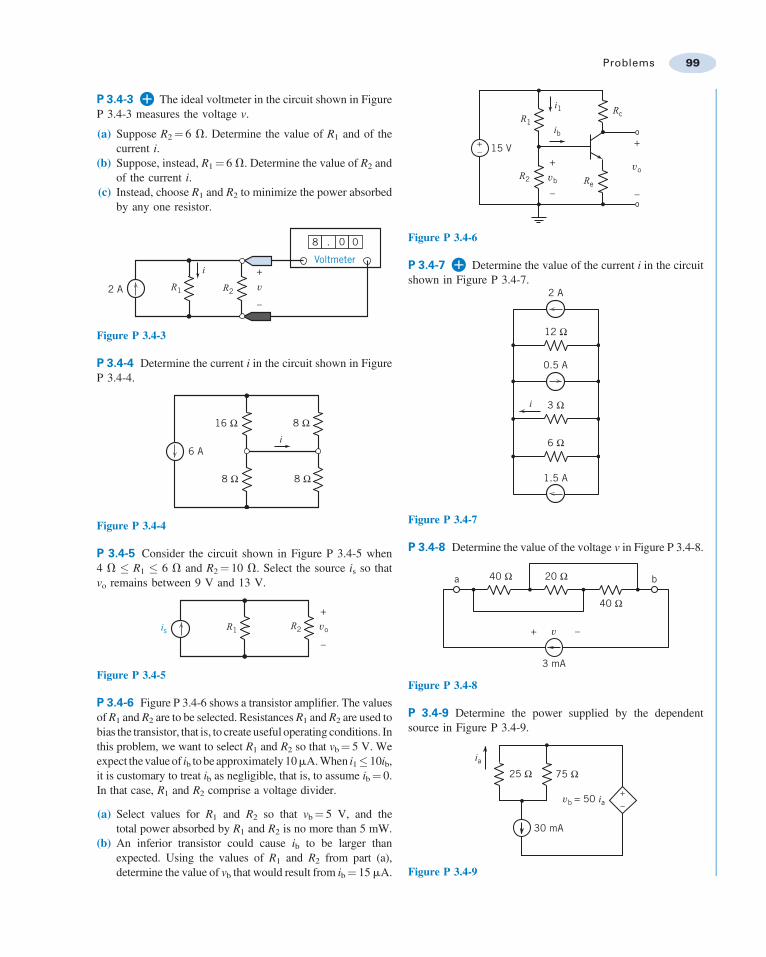
P 3.4-3 The ideal voltmeter in the circuit shown in FigureP 3.4-3 measures the voltage v.
(a) Suppose R2¼ 6 V. Determine the value of R1 and of thecurrent i.
(b) Suppose, instead, R1¼ 6 V. Determine the value of R2 andof the current i.
(c) Instead, choose R1 and R2 to minimize the power absorbedby any one resistor.
R1 R2
i
2 A
8 . 0 0
+Voltmeter
–
v
Figure P 3.4-3
P 3.4-4 Determine the current i in the circuit shown in FigureP 3.4-4.
16 Ω
8 Ω
8 Ω
8 Ω
i6 A
Figure P 3.4-4
P 3.4-5 Consider the circuit shown in Figure P 3.4-5 when4 V + R1 + 6 V and R2¼ 10 V. Select the source is so thatvo remains between 9 V and 13 V.
voR1 R2is
+
–
Figure P 3.4-5
P 3.4-6 Figure P 3.4-6 shows a transistor amplifier. The valuesof R1 and R2 are to be selected. Resistances R1 and R2 are used tobias the transistor, that is, to create useful operating conditions. Inthis problem, we want to select R1 and R2 so that vb¼ 5 V. Weexpect the value of ib to be approximately 10mA. When i1+ 10ib,it is customary to treat ib as negligible, that is, to assume ib¼ 0.In that case, R1 and R2 comprise a voltage divider.
(a) Select values for R1 and R2 so that vb¼ 5 V, and thetotal power absorbed by R1 and R2 is no more than 5 mW.
(b) An inferior transistor could cause ib to be larger thanexpected. Using the values of R1 and R2 from part (a),determine the value of vb that would result from ib¼ 15 mA.
vovb
R1
R2 Re
Rc
ib
i1
15 V+
–
+–
+
–
Figure P 3.4-6
P 3.4-7 Determine the value of the current i in the circuitshown in Figure P 3.4-7.
12 Ω
3 Ω
6 Ω
2 A
0.5 A
1.5 A
i
Figure P 3.4-7
P 3.4-8 Determine the value of the voltage v in Figure P 3.4-8.
v
40 Ω 20 Ω
40 Ω
a
+ –
3 mA
b
Figure P 3.4-8
P 3.4-9 Determine the power supplied by the dependentsource in Figure P 3.4-9.
ia
vb = 50 ia
75 Ω25 Ω
30 mA
+–
Figure P 3.4-9
Problems 99
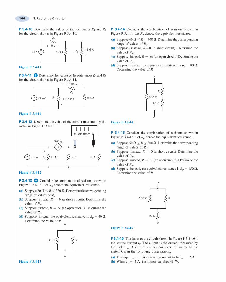
P 3.4-10 Determine the values of the resistances R1 and R2
for the circuit shown in Figure P 3.4-10.R1
R240 Ω24 V
8 V++
–
–1.6 A
Figure P 3.4-10
P 3.4-11 Determine the values of the resistances R1 and R2
for the circuit shown in Figure P 3.4-11.
R1
R2
+ –
80 Ω24 mA 19.2 mA
0.384 V
Figure P 3.4-11
P 3.4-12 Determine the value of the current measured by themeter in Figure P 3.4-12.
30 Ω 10 Ω
+
–
10 Ω1.2 A
Ammeter
0.2 va
va
Figure P 3.4-12
P 3.4-13 Consider the combination of resistors shown inFigure P 3.4-13. Let Rp denote the equivalent resistance.
(a) Suppose 20 V + R + 320 V. Determine the correspondingrange of values of Rp.
(b) Suppose, instead, R ¼ 0 (a short circuit). Determine thevalue of Rp.
(c) Suppose, instead, R ¼ 1 (an open circuit). Determine thevalue of Rp.
(d) Suppose, instead, the equivalent resistance is Rp ¼ 40 V.Determine the value of R.
R80 Ω
Figure P 3.4-13
P 3.4-14 Consider the combination of resistors shown inFigure P 3.4-l4. Let Rp denote the equivalent resistance.
(a) Suppose 40 V + R + 400 V. Determine the correspondingrange of values of Rp.
(b) Suppose, instead, R¼ 0 (a short circuit). Determine thevalue of Rp.
(c) Suppose, instead, R ¼ 1 (an open circuit). Determine thevalue of Rp.
(d) Suppose, instead, the equivalent resistance is Rp ¼ 80 V.Determine the value of R.
R
40 Ω
160 Ω
Figure P 3.4-14
P 3.4-15 Consider the combination of resistors shown inFigure P 3.4-15. Let Rp denote the equivalent resistance.
(a) Suppose 50 V + R + 800 V. Determine the correspondingrange of values of Rp.
(b) Suppose, instead, R ¼ 0 (a short circuit). Determine thevalue of Rp.
(c) Suppose, instead, R ¼ 1 (an open circuit). Determine thevalue of Rp.
(d) Suppose, instead, the equivalent resistance is Rp ¼ 150 V.Determine the value of R.
R
50 Ω
200 Ω
Figure P 3.4-15
P 3.4-16 The input to the circuit shown in Figure P 3.4-16 isthe source current is. The output is the current measured bythe meter io. A current divider connects the source to themeter. Given the following observations:
(a) The input is ¼ 5 A causes the output to be io ¼ 2 A.(b) When is ¼ 2 A, the source supplies 48 W.
100 3. Resistive Circuits

Determine the values of the resistances R1 and R2.
R1
R2
io
is
Ammeter
Figure P 3.4-16
P 3.4-17 Figure P 3.4-17 shows four similar but slightlydifferent circuits. Determine the values of the currents i1, i2,i3, and i4.
45 Ω 90 Ω300 mA
i 2
75 Ω 25 Ω320 mA
i 1
15 Ω 60 Ω500 mA
i 3
120 Ω 30 Ω250 mAi 4
Figure P 3.4-17
P 3.4-18 Figure P 3.4-18 shows four similar but slightlydifferent circuits. Determine the values of the currents i1, i2,i3, and i4.
240 mA i1
i2240 mA
60 Ω
40 Ω
60 Ω
30 Ω
60 Ω
i4
i3240 mA
240 mA
60 Ω
20 Ω 15 Ω
Figure P 3.4-18
P 3.4-19 The input to the circuit shown in Figure P 3.4-19 isthe current source current Is. The output is the current io. Theoutput of this circuit is proportion to the input, that is
io ¼ k Is
Determine the value of the constant of proportionality k.io
Is R R R
R
R
Figure P 3.4-19
P 3.4-20 The input to the circuit shown in Figure P 3.4-20 isthe voltage source voltage Vs. The output is the voltage vo.The output of this circuit is proportion to the input, that is
vo ¼ k V s
Determine the value of the constant of proportionality k.
Vs R R R
R
R
+–
R
R
+
–
vo
Figure P 3.4-20
Section 3.5 Series Voltage Sources and ParallelCurrent Sources
P 3.5-1 Determine the power supplied by each source inthe circuit shown in Figure P 3.5-1.
2 Ω 2 Ω
3 V
8 V
1.25 A3 A
+ –
+ –
Figure P 3.5-1
Problems 101
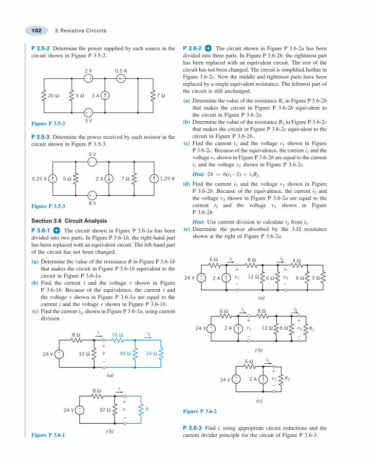
P 3.5-2 Determine the power supplied by each source in thecircuit shown in Figure P 3.5-2.
20 Ω 5 Ω 7 Ω3 A
3 V
2 V 0.5 A
+ –
+–
Figure P 3.5-2
P 3.5-3 Determine the power received by each resistor in thecircuit shown in Figure P 3.5-3.
5 Ω 7 Ω
8 V
2 A 1.25 A0.25 A
3 V
+ –
+ –
Figure P 3.5-3
Section 3.6 Circuit Analysis
P 3.6-1 The circuit shown in Figure P 3.6-1a has beendivided into two parts. In Figure P 3.6-1b, the right-hand parthas been replaced with an equivalent circuit. The left-hand partof the circuit has not been changed.
(a) Determine the value of the resistance R in Figure P 3.6-1bthat makes the circuit in Figure P 3.6-1b equivalent to thecircuit in Figure P 3.6-1a.
(b) Find the current i and the voltage v shown in FigureP 3.6-1b. Because of the equivalence, the current i andthe voltage v shown in Figure P 3.6-1a are equal to thecurrent i and the voltage v shown in Figure P 3.6-1b.
(c) Find the current i2, shown in Figure P 3.6-1a, using currentdivision.
v
v
R
i
i i2
( b)
(a)
32 Ω
32 Ω 48 Ω 24 Ω
16 Ω
8 Ω
8 Ω
24 V
24 V
+
–
+
–
+–
+–
Figure P 3.6-1
P 3.6-2 The circuit shown in Figure P 3.6-2a has beendivided into three parts. In Figure P 3.6-2b, the rightmost parthas been replaced with an equivalent circuit. The rest of thecircuit has not been changed. The circuit is simplified further inFigure 3.6-2c. Now the middle and rightmost parts have beenreplaced by a single equivalent resistance. The leftmost part ofthe circuit is still unchanged.
(a) Determine the value of the resistance R1 in Figure P 3.6-2bthat makes the circuit in Figure P 3.6-2b equivalent tothe circuit in Figure P 3.6-2a.
(b) Determine the value of the resistance R2 in Figure P 3.6-2cthat makes the circuit in Figure P 3.6-2c equivalent to thecircuit in Figure P 3.6-2b.
(c) Find the current i1 and the voltage v1 shown in FigureP 3.6-2c. Because of the equivalence, the current i1 and thevoltage v1 shown in Figure P 3.6-2b are equal to the currenti1 and the voltage v1 shown in Figure P 3.6-2c.
Hint: 24 ¼ 6(i1"2) þ i1R2
(d) Find the current i2 and the voltage v2 shown in FigureP 3.6-2b. Because of the equivalence, the current i2 andthe voltage v2 shown in Figure P 3.6-2a are equal to thecurrent i2 and the voltage v2 shown in FigureP 3.6-2b.
Hint: Use current division to calculate i2 from i1.(e) Determine the power absorbed by the 3-V resistance
shown at the right of Figure P 3.6-2a.
i1
(a)
i2
v2v1
+
–
+–
+
–
6 Ω
6 Ω 3 Ω6 Ω12 Ω
8 Ω 4 Ω
2 A24 V
v1 v2 R1
( b)
i2i1
+
–
+–
+
–
6 Ω 8 Ω
12 Ω 6 Ω24 V 2 A
v1 R2
(c)
i1
+
–
+–
6 Ω
24 V 2 A
Figure P 3.6-2
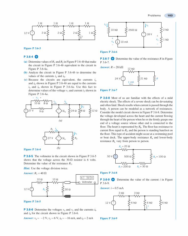
P 3.6-3 Find i, using appropriate circuit reductions and thecurrent divider principle for the circuit of Figure P 3.6-3.
102 3. Resistive Circuits
i
+– 2 Ω 2 Ω 2 Ω
1 Ω 1 Ω 1 Ω 1 Ω
1 Ω12 V
Figure P 3.6-3
P 3.6-4
(a) Determine values of R1 and R2 in Figure P 3.6-4b that makethe circuit in Figure P 3.6-4b equivalent to the circuit inFigure P 3.6-4a.
(b) Analyze the circuit in Figure P 3.6-4b to determine thevalues of the currents ia and ib.
(c) Because the circuits are equivalent, the currents iaand ib shown in Figure P 3.6-4b are equal to the currentsia and ib shown in Figure P 3.6-4a. Use this fact todetermine values of the voltage v1 and current i2 shown inFigure P 3.6-4a.
+
+
–+–
–
10 Ω 8 Ω
8 Ω 12 Ω9 Ω27 V 24 Ω
v1
ia
3ia
ib
i2
(a)
+ +27 V 3ia
ib
ia
– –
(b)
R1
R2
Figure P 3.6-4
P 3.6-5 The voltmeter in the circuit shown in Figure P 3.6-5shows that the voltage across the 30-V resistor is 6 volts.Determine the value of the resistance R1.
Hint: Use the voltage division twice.
Answer: R1¼ 40 V
R1+–
10 Ω 10 Ω
30 Ω
Voltmeter
6 0 0
12 V
Figure P 3.6-5
P 3.6-6 Determine the voltages va and vc and the currents iband id for the circuit shown in Figure P 3.6-6.
Answer: va¼ "2 V, vc¼ 6 V, ib¼"16 mA, and id¼ 2 mA
+
–
vc+
–va
ibid
18 V+–
10 kΩ 2500 Ω 2 kΩ
1 kΩ10 mA
Figure P 3.6-6
P 3.6-7 Determine the value of the resistance R in FigureP 3.6-7.
Answer: R¼ 28 kV
24 V1 mA
+–
12 kΩ
21 kΩ R
Figure P 3.6-7
P 3.6-8 Most of us are familiar with the effects of a mildelectric shock. The effects of a severe shock can be devastatingand often fatal. Shock results when current is passed through thebody. A person can be modeled as a network of resistances.Consider the model circuit shown in Figure P 3.6-8. Determinethe voltage developed across the heart and the current flowingthrough the heart of the person when he or she firmly grasps oneend of a voltage source whose other end is connected to thefloor. The heart is represented by Rh. The floor has resistance tocurrent flow equal to Rf, and the person is standing barefoot onthe floor. This type of accident might occur at a swimming poolor boat dock. The upper-body resistance Ru and lower-bodyresistance RL vary from person to person.
50 V +– 500 Ω
Ru = 20 Ω
Rf = 200 Ω
Rh = 100 Ω
RL = 30 Ω
Figure P 3.6-8
P 3.6-9 Determine the value of the current i in FigureP 3.6-9.
Answer: i¼ 0.5 mA
i12 V +
–
3 kΩ 3 kΩ
6 kΩ 6 kΩ 6 kΩ
Figure P 3.6-9
Problems 103
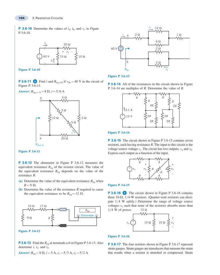
P 3.6-10 Determine the values of ia, ib, and vc in FigureP 3.6-10.
ia
ib60 V+
+–
–
15 Ω
20 Ω
10 Ω
vc
Figure P 3.6-10
P 3.6-11 Find i and Req a-b if vab¼ 40 V in the circuit ofFigure P 3.6-11.
Answer: Req a"b¼ 8 V, i¼ 5=6 A
b
a
12 Ω
20 Ω
3 Ω
2 Ω5 Ω
6 Ω
Req a–b
i
Figure P 3.6-11
P 3.6-12 The ohmmeter in Figure P 3.6-12 measures theequivalent resistance Req of the resistor circuit. The value ofthe equivalent resistance Req depends on the value of theresistance R.
(a) Determine the value of the equivalent resistance Req whenR¼ 9 V.
(b) Determine the value of the resistance R required to causethe equivalent resistance to be Req¼ 12 V.
Ohmmeter9 Ω
10 Ω 17 Ω
R
Req
Figure P 3.6-12
P 3.6-13 Find the Req at terminals a-b in Figure P 3.6-13. Alsodetermine i, i1, and i2.
Answer: Req¼ 8 V, i¼ 5 A, i1¼ 5=3 A, i2¼ 5=2 A
i1
i2
i
+
12 Ω
1 Ω
6 Ω
2 Ω
2 Ω
2 Ω
40 V
a
b
–
Req
Figure P 3.6-13
P 3.6-14 All of the resistances in the circuit shown in FigureP 3.6-14 are multiples of R. Determine the value of R.
RR
RR2R
2R
2R
2R
4R
3R
0.1 A
12 V+–
Figure P 3.6-14
P 3.6-15 The circuit shown in Figure P 3.6-15 contains sevenresistors, each having resistance R. The input to this circuit is thevoltage source voltage vs. The circuit has two outputs, va and vb.Express each output as a function of the input.
vs va vb
R
R
R
RR
R
R
++
–
–
+
–
Figure P 3.6-15
P 3.6-16 The circuit shown in Figure P 3.6-16 containsthree 10-V, 1=4-W resistors. (Quarter-watt resistors can dissi-pate 1=4 W safely.) Determine the range of voltage sourcevoltages vs such that none of the resistors absorbs more than1=4 W of power.
vovs+
+
––
10 Ω
10 Ω 10 Ω
Figure P 3.6-16
P 3.6-17 The four resistors shown in Figure P 3.6-17 representstrain gauges. Strain gauges are transducers that measure the strainthat results when a resistor is stretched or compressed. Strain
104 3. Resistive Circuits

gauges are used to measure force, displacement, or pressure. Thefour strain gauges in Figure P 3.6-17 each have a nominal(unstrained) resistance of 200 V and can each absorb 0.5 mWsafely. Determine the range of voltage source voltages vs such thatno strain gauge absorbs more than 0.5 mW of power.
vs
vo
+
−
200 Ω
200 Ω 200 Ω
200 Ω
+ –
Figure P 3.6-17
P 3.6-18 The circuit shown in Figure P 3.6-18b has beenobtained from the circuit shown in Figure P 3.6-18a byreplacing series and parallel combinations of resistances byequivalent resistances.
(a) Determine the values of the resistances R1, R2, and R3
in Figure P 3.6-18b so that the circuit shown in FigureP 3.6-18b is equivalent to the circuit shown in FigureP 3.6-18a.
(b) Determine the values of v1, v2, and i in FigureP 3.6-18b.
(c) Because the circuits are equivalent, the values of v1, v2, andi in Figure P 3.6-18a are equal to the values of v1, v2, and iin Figure P 3.6-18b. Determine the values of v4, i5, i6, andv7 in Figure P 3.6-18a.
+
+
+
–
–
–
24 V+– +
–
10 Ω
30 Ω
4 Ω
9 Ω18 Ω
6 Ω
6 Ω6 Ω
4 Ω
a
c
b
d
10 Ω
(a)
v1
i5
i6
i
v2
v7
v4
R1
R3
R2
24 V+–
4 Ω
a
c
b
d
(b)
i+– v2
+ –v1
Figure P 3.6-18
P 3.6-19 Determine the values of v1, v2, i3, v4, v5, and i6in Figure P 3.6-19.
+
+
–
–
24 V +–
4 Ω
6 Ω
80 Ω20 Ω
30 Ω
4 Ω
c
a
d
b
12 Ω
16 Ω
6 Ω
10 Ω
10 Ω
v1
+– v2
v5
+– v4
i3
i6
Figure P 3.6-19
P 3.6-20 Determine the values of i, v, and Req for the circuitshown in Figure P 3.6-20, given that vab¼ 18 V.
b
a
10 Ω
6 Ω
36 Ω
30 Ω
9 Ω72 Ω
Req
+
–v
i
Figure P 3.6-20
P 3.6-21 Determine the value of the resistance R in the circuitshown in Figure P 3.6-21, given that Req¼ 9 V .
Answer: R¼ 15 V
A
B
12 Ω
5 Ω 30 Ω
24 Ω
4 Ω
8 Ω
Req
R
Figure P 3.6-21
P 3.6-22 Determine the value of the resistance R in the circuitshown in Figure P 3.6-22, given that Req¼ 40 V.
Problems 105
R
R
R
R R
R
R
RReq
Figure P 3.6-22
P 3.6-23 Determine the values of r, the gain of the CCVS, and g,the gain of the VCCS, for the circuit shown in Figure P 3.6-23.
+
+
–
–
+
+
–
–vbria
ia
gvb12 V 9.74 V 6.09 V+–
8 Ω
8 Ω 8 Ω
Figure P 3.6-23
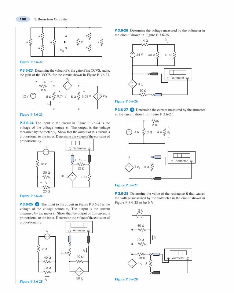
P 3.6-24 The input to the circuit in Figure P 3.6-24 is thevoltage of the voltage source vs. The output is the voltagemeasured by the meter, vo. Show that the output of this circuit isproportional to the input. Determine the value of the constant ofproportionality.
10 va
+ –vo
+ –va
vs
+ –
20 Ω
8 Ω
20 Ω
20 Ω12 Ω
Voltmeter
+–
Figure P 3.6-24
P 3.6-25 The input to the circuit in Figure P 3.6-25 is thevoltage of the voltage source vs. The output is the currentmeasured by the meter io. Show that the output of this circuit isproportional to the input. Determine the value of the constant ofproportionality.
vs Ammeter
+ –
2 Ω20 Ω
40 Ω40 Ω
10 Ω
50 ia
io
iaFigure P 3.6-25
P 3.6-26 Determine the voltage measured by the voltmeter inthe circuit shown in Figure P 3.6-26.
ia
8 ia
24 V
+–
+–
10 Ω
40 Ω 10 Ω
4 Ω
Voltmeter
Figure P 3.6-26
P 3.6-27 Determine the current measured by the ammeterin the circuit shown in Figure P 3.6-27.
+
–
va
8 va
3 A
2 Ω
4 Ω3 Ω
10 Ω
Ammeter
Figure P 3.6-27
P 3.6-28 Determine the value of the resistance R that causesthe voltage measured by the voltmeter in the circuit shown inFigure P 3.6-28 to be 6 V.
Voltmeter
+–
ia
5 ia R
3 A
40 Ω
10 Ω
18 Ω
Figure P 3.6-28
106 3. Resistive Circuits
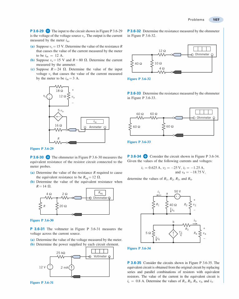
P 3.6-29 The input to the circuit shown in Figure P 3.6-29is the voltage of the voltage source vs. The output is the currentmeasured by the meter im.
(a) Suppose vs ¼ 15 V. Determine the value of the resistance Rthat causes the value of the current measured by the meterto be im ¼ 12 A.
(b) Suppose vs¼ 15 V and R¼ 80 V. Determine the currentmeasured by the ammeter.
(c) Suppose R¼ 24 V. Determine the value of the inputvoltage vs that causes the value of the current measuredby the meter to be im¼ 3 A.
5 va
im
+
–
vavs
18 Ω
12 Ω
16 Ω Ammeter
+–
R
Figure P 3.6-29
P 3.6-30 The ohmmeter in Figure P 3.6-30 measures theequivalent resistance of the resistor circuit connected to themeter probes.
(a) Determine the value of the resistance R required to causethe equivalent resistance to be Req¼ 12 V.
(b) Determine the value of the equivalent resistance whenR¼ 14 V.
Req
Ohmmeter4 Ω 2 Ω
20 ΩR
Figure P 3.6-30
P 3.6-31 The voltmeter in Figure P 3.6-31 measures thevoltage across the current source.
(a) Determine the value of the voltage measured by the meter.(b) Determine the power supplied by each circuit element.
2 mA12 V +–
25 kΩVoltmeter
Figure P 3.6-31
P 3.6-32 Determine the resistance measured by the ohmmeterin Figure P 3.6-32.
Ohmmeter
4 Ω
10 Ω
12 Ω
40 Ω
Figure P 3.6-32
P 3.6-33 Determine the resistance measured by the ohmmeterin Figure P 3.6-33.
Ohmmeter
60 Ω60 Ω
60 Ω 60 Ω
Figure P 3.6-33
P 3.6-34 Consider the circuit shown in Figure P 3.6-34.Given the values of the following currents and voltages:
i1 ¼ 0:625 A; v2 ¼ "25 V; i3 ¼ "1:25 A;and v4 ¼ "18:75 V;
determine the values of R1, R2, R3, and R4.
v2
v2 v4
i3
i6
i1
i5
R2
R4
R3
R1
+ –
40 Ω
5 Ω
+
–
+
–
50 Va
b
4
Figure P 3.6-34
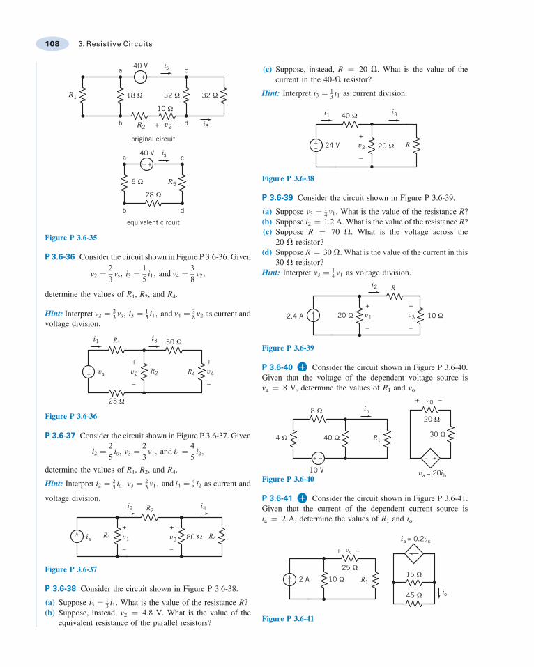
P 3.6-35 Consider the circuits shown in Figure P 3.6-35. Theequivalent circuit is obtained from the original circuit by replacingseries and parallel combinations of resistors with equivalentresistors. The value of the current in the equivalent circuit isis ¼ 0.8 A. Determine the values of R1, R2, R5, v2, and i3.
Problems 107
a
b
a
b
c
d
c
dv2+ –
– +
– +
40 V
original circuit
equivalent circuit
40 V
18 Ω 32 Ω
28 Ω
10 Ω
32 ΩR1
R2
is
is
i3
R56 Ω
Figure P 3.6-35
P 3.6-36 Consider the circuit shown in Figure P 3.6-36. Given
v2 ¼23
vs; i3 ¼15
i1; and v4 ¼38
v2;
determine the values of R1, R2, and R4.
Hint: Interpret v2 ¼ 23 vs; i3 ¼ 1
5 i1; and v4 ¼ 38 v2 as current and
voltage division.
+
–
+
–
i1 i3
v4v2vs
R1
R2 R4+–
50 Ω
25 Ω
Figure P 3.6-36
P 3.6-37 Consider the circuit shown in Figure P 3.6-37. Given
i2 ¼25
is; v3 ¼23
v1; and i4 ¼45
i2;
determine the values of R1, R2, and R4.
Hint: Interpret i2 ¼ 25 is; v3 ¼ 2
3 v1; and i4 ¼ 45 i2 as current and
voltage division.
+
–
+
–
is
i2 i4
v1 v3R1 R4
R2
80 Ω
Figure P 3.6-37
P 3.6-38 Consider the circuit shown in Figure P 3.6-38.
(a) Suppose i3 ¼ 13 i1. What is the value of the resistance R?
(b) Suppose, instead, v2 ¼ 4.8 V. What is the value of theequivalent resistance of the parallel resistors?
(c) Suppose, instead, R ¼ 20 V. What is the value of thecurrent in the 40-V resistor?
Hint: Interpret i3 ¼ 13 i1 as current division.
+
–
i1 i3
v2 R
40 Ω
24 V 20 Ω+–
Figure P 3.6-38
P 3.6-39 Consider the circuit shown in Figure P 3.6-39.
(a) Suppose v3 ¼ 14 v1. What is the value of the resistance R?
(b) Suppose i2 ¼ 1.2 A. What is the value of the resistance R?(c) Suppose R ¼ 70 V. What is the voltage across the
20-V resistor?(d) Suppose R ¼ 30 V. What is the value of the current in this
30-V resistor?Hint: Interpret v3 ¼ 1
4 v1 as voltage division.
+
–
i2
v1
+
–
v3
R
20 Ω 10 Ω2.4 A
Figure P 3.6-39
P 3.6-40 Consider the circuit shown in Figure P 3.6-40.Given that the voltage of the dependent voltage source isva ¼ 8 V, determine the values of R1 and vo.
vO
va = 20ib
ib+ –
+ – +–
8 Ω
40 Ω 30 Ω
20 Ω
4 Ω R1
10 VFigure P 3.6-40
P 3.6-41 Consider the circuit shown in Figure P 3.6-41.Given that the current of the dependent current source isia ¼ 2 A, determine the values of R1 and io.
+ –vc
R1
io
2 A 10 Ω
45 Ω
15 Ω25 Ω
ia = 0.2vc
Figure P 3.6-41
108 3. Resistive Circuits
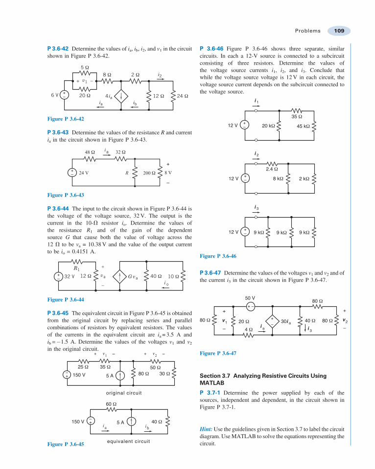
P 3.6-42 Determine the values of ia, ib, i2, and v1 in the circuitshown in Figure P 3.6-42.
i2
ibia
v1
12 Ω 24 Ω4 ia
2 Ω8 Ω5 Ω
20 Ω6 V
+ –
+–
Figure P 3.6-42
P 3.6-43 Determine the values of the resistance R and currentia in the circuit shown in Figure P 3.6-43.
200 Ω
32 Ω
24 V R
ia
+–
48 Ω
8 V
+
–
Figure P 3.6-43
P 3.6-44 The input to the circuit shown in Figure P 3.6-44 isthe voltage of the voltage source, 32 V. The output is thecurrent in the 10-V resistor io. Determine the values ofthe resistance R1 and of the gain of the dependentsource G that cause both the value of voltage across the12 V to be va = 10.38 V and the value of the output currentto be io = 0.4151 A.
+– 12 Ω va
+
–
32 V
R1
G va 40 Ω 10 Ωi o
Figure P 3.6-44
P 3.6-45 The equivalent circuit in Figure P 3.6-45 is obtainedfrom the original circuit by replacing series and parallelcombinations of resistors by equivalent resistors. The valuesof the currents in the equivalent circuit are ia = 3.5 A andib ="1.5 A. Determine the values of the voltages v1 and v2
in the original circuit.
+–
+–
ia ib
+ v1 _ + v2
_
150 V
150 V 5 A
5 A 40 Ω
60 Ω
25 Ω 35 Ω80 Ω
50 Ω30 Ω
original circuit
equivalent circuitFigure P 3.6-45
P 3.6-46 Figure P 3.6-46 shows three separate, similarcircuits. In each a 12-V source is connected to a subcircuitconsisting of three resistors. Determine the values ofthe voltage source currents i1, i2, and i3. Conclude thatwhile the voltage source voltage is 12 V in each circuit, thevoltage source current depends on the subcircuit connected tothe voltage source.
12 V
35 Ω
i 1
+– 20 kΩ 45 kΩ
12 V
2.4 Ω
i 2
+– 8 kΩ 2 kΩ
12 V
i 3
+– 9 kΩ 9 kΩ9 kΩ
Figure P 3.6-46
P 3.6-47 Determine the values of the voltages v1 and v2 and ofthe current i3 in the circuit shown in Figure P 3.6-47.
4 Ω
40 Ω
50 V
+– 30i a
80 Ω
80 Ω 20 Ωi 3
+
–v1
i a
80 Ω
+
–v2
+ –
Figure P 3.6-47
Section 3.7 Analyzing Resistive Circuits UsingMATLAB
P 3.7-1 Determine the power supplied by each of thesources, independent and dependent, in the circuit shown inFigure P 3.7-1.
Hint: Use the guidelines given in Section 3.7 to label the circuitdiagram. Use MATLAB to solve the equations representing thecircuit.
Problems 109
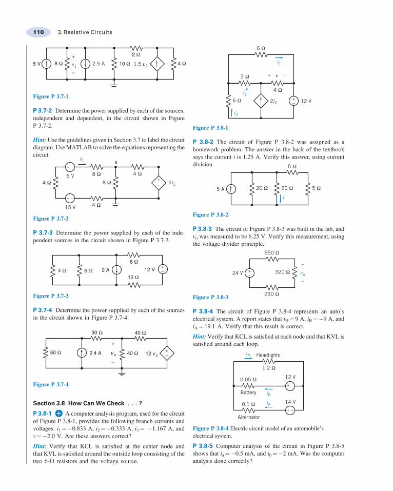
5 V 8 Ω2 Ω
4 Ω10 Ω+
–v1 2.5 A 1.5 v1
Figure P 3.7-1
P 3.7-2 Determine the power supplied by each of the sources,independent and dependent, in the circuit shown in FigureP 3.7-2.
Hint: Use the guidelines given in Section 3.7 to label the circuitdiagram. Use MATLAB to solve the equations representing thecircuit.
i1
5i1
15 V
a+ –
+
+
–
–4 Ω
8 Ω
8 Ω
4 Ω
6 V 4 Ω
Figure P 3.7-2
P 3.7-3 Determine the power supplied by each of the inde-pendent sources in the circuit shown in Figure P 3.7-3.
+–6 Ω 2 A
8 Ω4 Ω 12 V
12 Ω
Figure P 3.7-3
P 3.7-4 Determine the power supplied by each of the sourcesin the circuit shown in Figure P 3.7-4.
30 Ω
40 Ω2.4 A 12 v c
40 Ω
50 Ω+
–v c
+–
Figure P 3.7-4
Section 3.8 How CanWe Check . . . ?
P 3.8-1 A computer analysis program, used for the circuitof Figure P 3.8-1, provides the following branch currents andvoltages: i1¼"0.833 A, i2¼"0.333 A, i3¼ "1.167 A, andv¼"2.0 V. Are these answers correct?
Hint: Verify that KCL is satisfied at the center node andthat KVL is satisfied around the outside loop consisting of thetwo 6-V resistors and the voltage source.
i1
2i2
i2
i3
12 V+–
+ –
6 Ω
6 Ω
4 Ω
3 Ω v
Figure P 3.8-1
P 3.8-2 The circuit of Figure P 3.8-2 was assigned as ahomework problem. The answer in the back of the textbooksays the current i is 1.25 A. Verify this answer, using currentdivision.
i5 A
5 Ω
5 Ω20 Ω20 Ω
Figure P 3.8-2
P 3.8-3 The circuit of Figure P 3.8-3 was built in the lab, andvo was measured to be 6.25 V. Verify this measurement, usingthe voltage divider principle.
vo24 V
650 Ω
320 Ω
230 Ω
+
–
+–
Figure P 3.8-3
P 3.8-4 The circuit of Figure P 3.8-4 represents an auto’selectrical system. A report states that iH¼ 9 A, iB¼"9 A, andiA¼ 19.1 A. Verify that this result is correct.
Hint: Verify that KCL is satisfied at each node and that KVL issatisfied around each loop.
iBiA
iH
Alternator
Battery
12 V
14 V
Headlights
+ –
+ –
1.2 Ω
0.1 Ω
0.05 Ω
Figure P 3.8-4 Electric circuit model of an automobile’selectrical system.
P 3.8-5 Computer analysis of the circuit in Figure P 3.8-5shows that ia¼"0.5 mA, and ib¼"2 mA. Was the computeranalysis done correctly?
110 3. Resistive Circuits
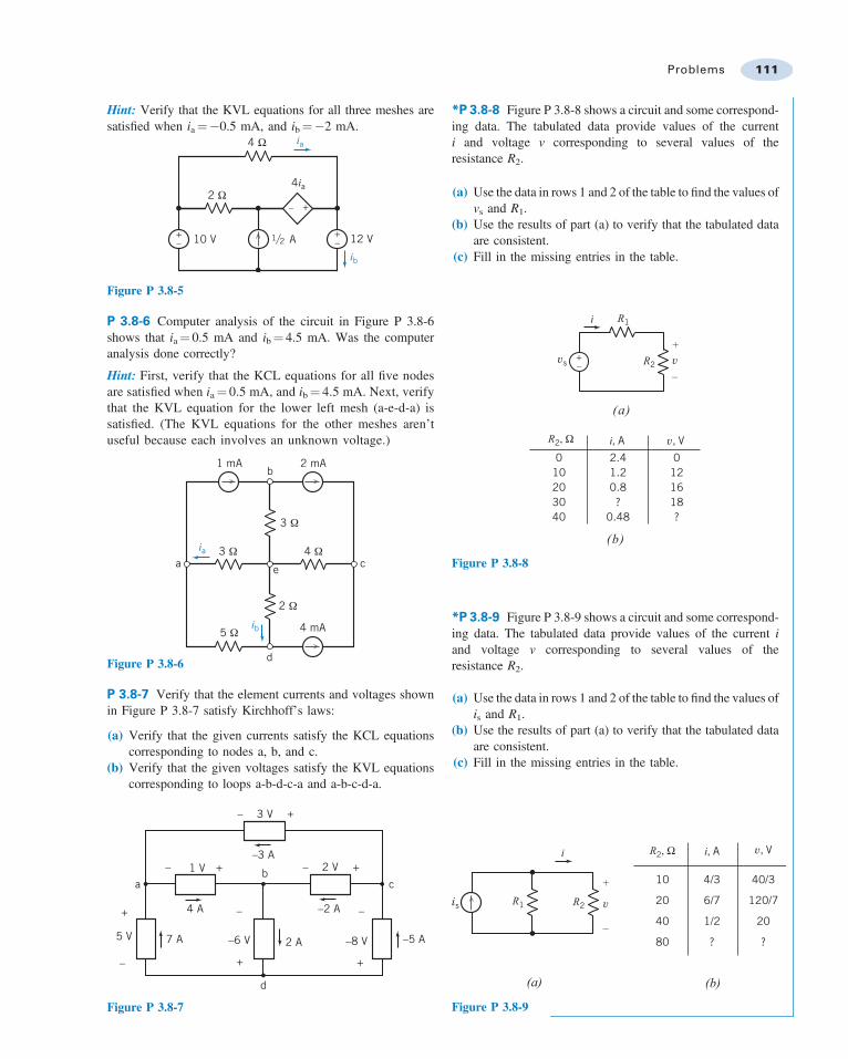
Hint: Verify that the KVL equations for all three meshes aresatisfied when ia¼"0.5 mA, and ib¼"2 mA.
4ia
ia
ib
12 VA110 V+
+
–
–
+–
4 Ω
2 Ω
2
Figure P 3.8-5
P 3.8-6 Computer analysis of the circuit in Figure P 3.8-6shows that ia¼ 0.5 mA and ib¼ 4.5 mA. Was the computeranalysis done correctly?
Hint: First, verify that the KCL equations for all five nodesare satisfied when ia ¼ 0.5 mA, and ib ¼ 4.5 mA. Next, verifythat the KVL equation for the lower left mesh (a-e-d-a) issatisfied. (The KVL equations for the other meshes aren’tuseful because each involves an unknown voltage.)
1 mA 2 mA
e c
d
b
a
4 mA
ia
ib5 Ω
2 Ω
4 Ω
3 Ω
3 Ω
Figure P 3.8-6
P 3.8-7 Verify that the element currents and voltages shownin Figure P 3.8-7 satisfy Kirchhoff’s laws:
(a) Verify that the given currents satisfy the KCL equationscorresponding to nodes a, b, and c.
(b) Verify that the given voltages satisfy the KVL equationscorresponding to loops a-b-d-c-a and a-b-c-d-a.
+
+
+
–
+
+
+
–
–
––a c
b
d
3 V
2 V–3 A
–2 A
–6 V
4 A
7 A –5 A–8 V
–
1 V
5 V 2 A
Figure P 3.8-7
*P 3.8-8 Figure P 3.8-8 shows a circuit and some correspond-ing data. The tabulated data provide values of the currenti and voltage v corresponding to several values of theresistance R2.
(a) Use the data in rows 1 and 2 of the table to find the values ofvs and R1.
(b) Use the results of part (a) to verify that the tabulated dataare consistent.
(c) Fill in the missing entries in the table.
R1
R2
R2, Ω
vs
+
–v+
–
i
i, A
(a)
(b)
3040
20100
?0.48
0.81.22.4
v, V
18?
16120
Figure P 3.8-8
*P 3.8-9 Figure P 3.8-9 shows a circuit and some correspond-ing data. The tabulated data provide values of the current iand voltage v corresponding to several values of theresistance R2.
(a) Use the data in rows 1 and 2 of the table to find the values ofis and R1.
(b) Use the results of part (a) to verify that the tabulated dataare consistent.
(c) Fill in the missing entries in the table.
R1 R2
R2, Ω
is
+
–
v
i i, A
(a) (b)
80
40
20
10
?
1/2
6/7
4/3
v, V
?
20
120/7
40/3
Figure P 3.8-9
Problems 111
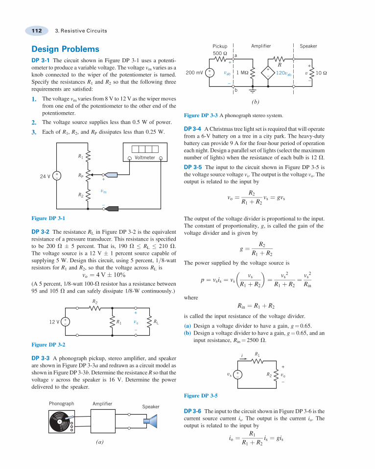
Design ProblemsDP 3-1 The circuit shown in Figure DP 3-1 uses a potenti-ometer to produce a variable voltage. The voltage vm varies as aknob connected to the wiper of the potentiometer is turned.Specify the resistances R1 and R2 so that the following threerequirements are satisfied:
1. The voltage vm varies from 8 V to 12 V as the wiper movesfrom one end of the potentiometer to the other end of thepotentiometer.
2. The voltage source supplies less than 0.5 W of power.
3. Each of R1, R2, and RP dissipates less than 0.25 W.
R1
R2
RP24 V
Voltmeter
+–
vm
+
–
Figure DP 3-1
DP 3-2 The resistance RL in Figure DP 3-2 is the equivalentresistance of a pressure transducer. This resistance is specifiedto be 200 V , 5 percent. That is, 190 V + RL + 210 V.The voltage source is a 12 V , 1 percent source capable ofsupplying 5 W. Design this circuit, using 5 percent, 1=8-wattresistors for R1 and R2, so that the voltage across RL is
vo ¼ 4 V, 10%(A 5 percent, 1/8-watt 100-V resistor has a resistance between95 and 105 V and can safely dissipate 1/8-W continuously.)
12 V
+
–
+– R1 RL
R2
vo
Figure DP 3-2
DP 3-3 A phonograph pickup, stereo amplifier, and speakerare shown in Figure DP 3-3a and redrawn as a circuit model asshown in Figure DP 3-3b. Determine the resistance R so that thevoltage v across the speaker is 16 V. Determine the powerdelivered to the speaker.
Phonograph Amplifier Speaker
(a)
vab v–
+R
120vab
+
–
200 mV +–
+
–
a
b
Speaker
(b)
Amplifier
1 MΩ 10 Ω
Pickup500 Ω
Figure DP 3-3 A phonograph stereo system.
DP 3-4 A Christmas tree light set is required that will operatefrom a 6-V battery on a tree in a city park. The heavy-dutybattery can provide 9 A for the four-hour period of operationeach night. Design a parallel set of lights (select the maximumnumber of lights) when the resistance of each bulb is 12 V.
DP 3-5 The input to the circuit shown in Figure DP 3-5 isthe voltage source voltage vs. The output is the voltage vo. Theoutput is related to the input by
vo ¼R2
R1 þ R2vs ¼ gvs
The output of the voltage divider is proportional to the input.The constant of proportionality, g, is called the gain of thevoltage divider and is given by
g ¼ R2
R1 þ R2
The power supplied by the voltage source is
p ¼ vsis ¼ vsvs
R1 þ R2
! "¼ vs2
R1 þ R2¼ vs2
Rin
whereRin ¼ R1 þ R2
is called the input resistance of the voltage divider.
(a) Design a voltage divider to have a gain, g¼ 0.65.(b) Design a voltage divider to have a gain, g¼ 0.65, and an
input resistance, Rin¼ 2500 V.
R2
R1
vs vo
i
+–
+
–
Figure DP 3-5
DP 3-6 The input to the circuit shown in Figure DP 3-6 is thecurrent source current is. The output is the current io. Theoutput is related to the input by
io ¼R1
R1 þ R2is ¼ gis
112 3. Resistive Circuits
The output of the current divider is proportional to the input.The constant of proportionality g is called the gain of thecurrent divider and is given by
g ¼ R1
R1 þ R2
The power supplied by the current source is
p ¼ vsis ¼ isR1R2
R1 þ R2
! "% &is ¼
R1R2
R1 þ R2is2 ¼ Rinis2
where
Rin ¼R1R2
R1 þ R2
is called the input resistance of the current divider.
(a) Design a current divider to have a gain, g¼ 0.65.(b) Design a current divider to have a gain, g¼ 0.65, and an
input resistance, Rin¼ 10000 V.
R2R1vsis
io
+
–
Figure DP 3-6
DP 3-7 Design the circuit shown in Figure DP 3-7 to have anoutput vo¼ 8.5 V when the input is vs¼ 12 V. The circuitshould require no more than 1 mW from the voltage source.
R2
R1
vs vo
i
+–
+
–
Figure DP 3-7
DP 3-8 Design the circuit shown in Figure DP 3-8 to have anoutput io¼ 1.8 mA when the input is is¼ 5 mA. The circuit shouldrequire no more than 1 mW from the current source.
R1 R2vsis
io
+
–
Figure DP 3-8
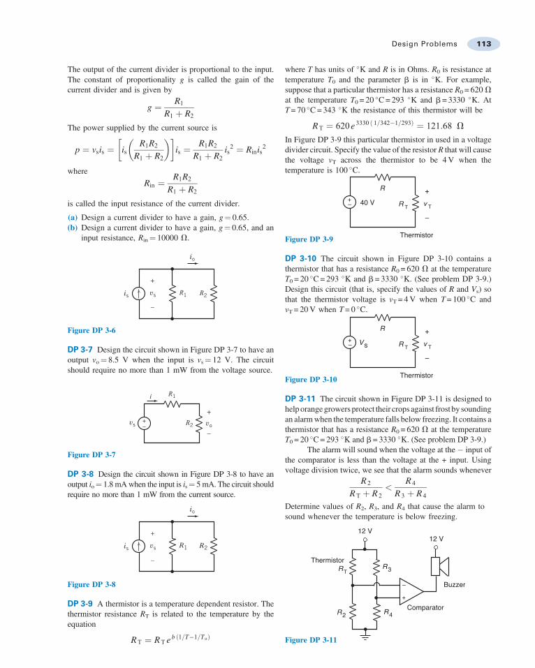
DP 3-9 A thermistor is a temperature dependent resistor. Thethermistor resistance RT is related to the temperature by theequation
RT ¼ RT e b 1=T"1=Toð Þ
where T has units of 'K and R is in Ohms. R0 is resistance attemperature T0 and the parameter b is in 'K. For example,suppose that a particular thermistor has a resistance R0 = 620 Vat the temperature T0 = 20 'C = 293 'K and b= 3330 'K. AtT = 70 'C = 343 'K the resistance of this thermistor will be
RT ¼ 620e 3330 1=342"1=293ð Þ ¼ 121:68 V
In Figure DP 3-9 this particular thermistor in used in a voltagedivider circuit. Specify the value of the resistor R that will causethe voltage vT across the thermistor to be 4 V when thetemperature is 100 'C.
+– 40 V
R
Thermistor
R T v T
+
–
Figure DP 3-9
DP 3-10 The circuit shown in Figure DP 3-10 contains athermistor that has a resistance R0 = 620 V at the temperatureT0 = 20 'C = 293 'K and b= 3330 'K. (See problem DP 3-9.)Design this circuit (that is, specify the values of R and Vs) sothat the thermistor voltage is vT = 4 V when T = 100 'C andvT = 20 V when T = 0 'C.
+– Vs
R
Thermistor
R T v T
+
–
Figure DP 3-10
DP 3-11 The circuit shown in Figure DP 3-11 is designed tohelp orange growers protect their crops against frost by soundingan alarm when the temperature falls below freezing. It contains athermistor that has a resistance R0 = 620 V at the temperatureT0 = 20 'C = 293 'K and b= 3330 'K. (See problem DP 3-9.)
The alarm will sound when the voltage at the " input ofthe comparator is less than the voltage at the + input. Usingvoltage division twice, we see that the alarm sounds whenever
R 2
RT þ R 2<
R 4
R 3 þ R 4
Determine values of R2, R3, and R4 that cause the alarm tosound whenever the temperature is below freezing.
–
+
12 V
R3
R4R2
RT
Thermistor
12 V
Comparator
Buzzer
Figure DP 3-11
Design Problems 113