Embed Size (px)
Citation preview
23/12/2003
ComplyIT
Trip Requirement and Availability Calculator (TRAC)
User Guide
Version 1.9(30)
3BGB200004-D0002 A
Page 2 of 109 © ABB 2003
Notice
The information in this document is subject to change without notice and should not be construed as a commitment by ABB. ABB assumes no responsibility for any errors that may appear in this document.
In no event shall ABB be liable for direct, indirect, special, incidental or consequential damages of any nature or kind arising from the use of this document, nor shall ABB be liable for incidental or consequential damages arising from use of any software or hardware described in this document.
This document and parts thereof must not be reproduced or copied without written permission from ABB, and the contents thereof must not be imparted to a third party nor used for any unauthorized purpose.
The software or hardware described in this document is furnished under a license and may be used, copied, or disclosed only in accordance with the terms of such license.
Copyright © 2004 ABB
All rights reserved.
Release: January 2004
Document number: 3BGB200004 - D0002 A
TRADEMARKS Registrations and trademarks used in this document include:
Microsoft Registered trademark of Microsoft Corporation.
Windows Registered trademark of Microsoft Corporation.
ComplyIT Trademark of ABB.
3BGB200004-D0002 A
Page 3 of 109 © ABB 2003
TRAC
Trip Requirement and Availability Calculator
TRAC is a validated, professionally developed package for Instrumented Protection System SIL Determination and Design in accordance with IEC 61508 & IEC 61511.
User Guide
1 Product Description..................................................................... 5 2 Getting Started............................................................................ 6 3 TRAC User Guidance ............................................................... 38 4 TRAC Roles .............................................................................. 60 5 Frequently Asked Questions..................................................... 61 6 System Requirements............................................................... 67 7 Overview of TRAC Installation.................................................. 68 8 Installation Flowchart ................................................................ 69 9 How to Install a TRAC Client .................................................... 71 10 How to install the Server ........................................................ 73 11 Licensing TRAC ..................................................................... 72 12 Configuring the Server on your Network................................ 76 13 Configuring a Client on your Network .................................... 81 Appendix A - Main Menu.................................................................. 93 Appendix B - Server and Database Security ................................... 96 Appendix C - Strong Passwords .................................................... 100 Appendix D - Software Licence Agreement ................................... 101 Appendix E - Further Information and Support .............................. 109
3BGB200004-D0002 A
Page 4 of 109 © ABB 2003
Welcome to TRAC. This User Guide provides an introduction to the basics behind TRAC, its user interface and the database that has been designed to be flexible and configurable to meet your needs. This User Guide covers TRAC versions 1.9(30) onwards.
3BGB200004-D0002 A
Page 5 of 109 © ABB 2003
1 Product Description TRAC is a proven approach for the SIL assessment, architectural technical specifications and data storage, of plant instrumented safety or product critical systems.
TRAC uses a new software package that has been professionally developed and fully validated by ABB. The software is designed to simplify the task of managing data with ease of use, based on standard Microsoft PC technology. The system is supplied via a licensed agreement with ABB and comes complete with the necessary backup support.
The product is based on the highly successful BP developed Trip Test Interval Calculator ‘TTIC’ system, developed specifically for the chemicals and related sectors, which has been in existence since 1997. TRAC incorporates the proven features of the ‘TTIC’ system in addition to new features designed to take into account new user features and in accordance with the requirements of IEC 61508 & IEC 61511.
Benefits
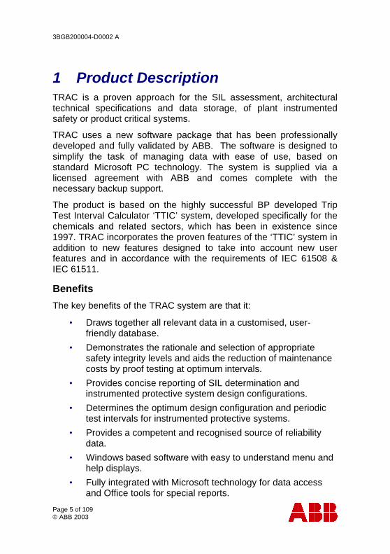
The key benefits of the TRAC system are that it:
• Draws together all relevant data in a customised, user-friendly database.
• Demonstrates the rationale and selection of appropriate safety integrity levels and aids the reduction of maintenance costs by proof testing at optimum intervals.
• Provides concise reporting of SIL determination and instrumented protective system design configurations.
• Determines the optimum design configuration and periodic test intervals for instrumented protective systems.
• Provides a competent and recognised source of reliability data.
• Windows based software with easy to understand menu and help displays.
• Fully integrated with Microsoft technology for data access and Office tools for special reports.
3BGB200004-D0002 A
Page 6 of 109 © ABB 2003
2 Getting Started Having installed the TRAC software (see section 7), first ensure the server that your TRAC database is located on, is running.
• For networked TRAC installations, this is done by your TRAC System Administrator.
• For stand alone TRAC installations, use the icon on the taskbar, or select Windows menu item Programs, MSDE, Service Manager.
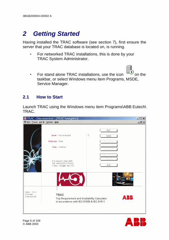
2.1 How to Start
Launch TRAC using the Windows menu item Programs\ABB Eutech\ TRAC.
3BGB200004-D0002 A
Page 7 of 109 © ABB 2003
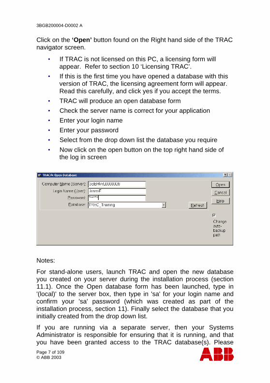
Click on the ‘Open’ button found on the Right hand side of the TRAC navigator screen.
• If TRAC is not licensed on this PC, a licensing form will appear. Refer to section 10 ‘Licensing TRAC’.
• If this is the first time you have opened a database with this version of TRAC, the licensing agreement form will appear. Read this carefully, and click yes if you accept the terms.
• TRAC will produce an open database form
• Check the server name is correct for your application
• Enter your login name
• Enter your password
• Select from the drop down list the database you require
• Now click on the open button on the top right hand side of the log in screen
Notes:
For stand-alone users, launch TRAC and open the new database you created on your server during the installation process (section 11.1). Once the Open database form has been launched, type in '(local)' to the server box, then type in 'sa' for your login name and confirm your 'sa' password (which was created as part of the installation process, section 11). Finally select the database that you initially created from the drop down list.
If you are running via a separate server, then your Systems Administrator is responsible for ensuring that it is running, and that you have been granted access to the TRAC database(s). Please
3BGB200004-D0002 A
Page 8 of 109 © ABB 2003
contact your Systems Administrator for you login name and initial password.
TRAC may ask if you wish to create an automatic backup of the chosen database (section 13.4).
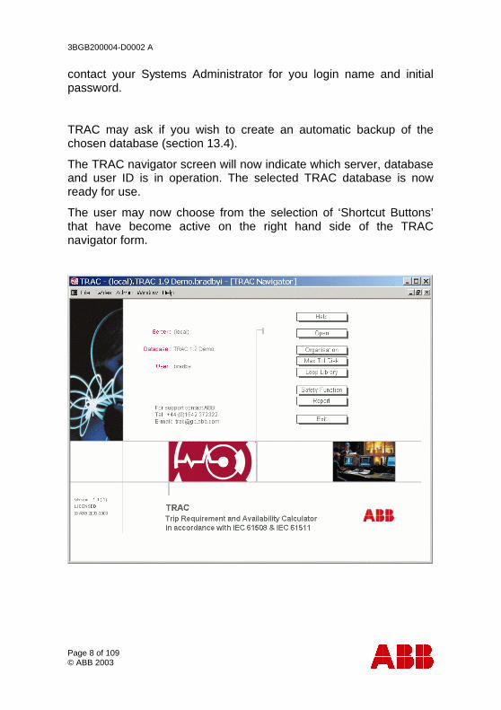
The TRAC navigator screen will now indicate which server, database and user ID is in operation. The selected TRAC database is now ready for use.
The user may now choose from the selection of ‘Shortcut Buttons’ that have become active on the right hand side of the TRAC navigator form.
3BGB200004-D0002 A
Page 9 of 109 © ABB 2003
2.2 The Navigator
TRAC has been designed so the navigation buttons the user is required to follow to successfully utilise the tool are in sequential order starting from at the top and working down.
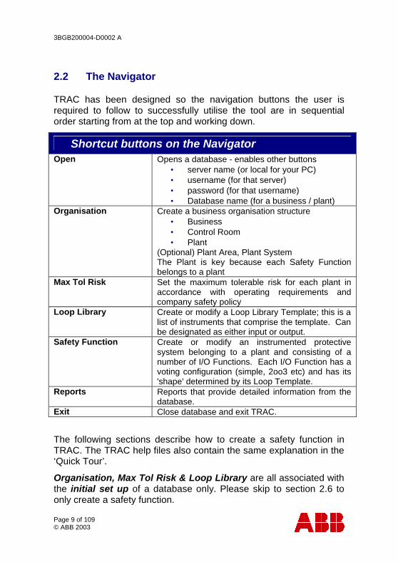
• Shortcut buttons on the Navigator Open Opens a database - enables other buttons
• server name (or local for your PC) • username (for that server) • password (for that username) • Database name (for a business / plant)
Organisation Create a business organisation structure • Business • Control Room • Plant
(Optional) Plant Area, Plant System The Plant is key because each Safety Function belongs to a plant
Max Tol Risk Set the maximum tolerable risk for each plant in accordance with operating requirements and company safety policy
Loop Library
Create or modify a Loop Library Template; this is a list of instruments that comprise the template. Can be designated as either input or output.
Safety Function Create or modify an instrumented protective system belonging to a plant and consisting of a number of I/O Functions. Each I/O Function has a voting configuration (simple, 2oo3 etc) and has its 'shape' determined by its Loop Template.
Reports
Reports that provide detailed information from the database.
Exit Close database and exit TRAC.
The following sections describe how to create a safety function in TRAC. The TRAC help files also contain the same explanation in the ‘Quick Tour’.
Organisation, Max Tol Risk & Loop Library are all associated with the initial set up of a database only. Please skip to section 2.6 to only create a safety function.
3BGB200004-D0002 A
Page 10 of 109 © ABB 2003
2.3 Organisation
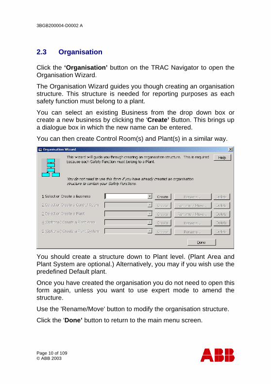
Click the ‘Organisation’ button on the TRAC Navigator to open the Organisation Wizard.
The Organisation Wizard guides you though creating an organisation structure. This structure is needed for reporting purposes as each safety function must belong to a plant.
You can select an existing Business from the drop down box or create a new business by clicking the ‘Create’ Button. This brings up a dialogue box in which the new name can be entered.
You can then create Control Room(s) and Plant(s) in a similar way.
You should create a structure down to Plant level. (Plant Area and Plant System are optional.) Alternatively, you may if you wish use the predefined Default plant.
Once you have created the organisation you do not need to open this form again, unless you want to use expert mode to amend the structure.
Use the 'Rename/Move' button to modify the organisation structure.
Click the ‘Done’ button to return to the main menu screen.
3BGB200004-D0002 A
Page 11 of 109 © ABB 2003
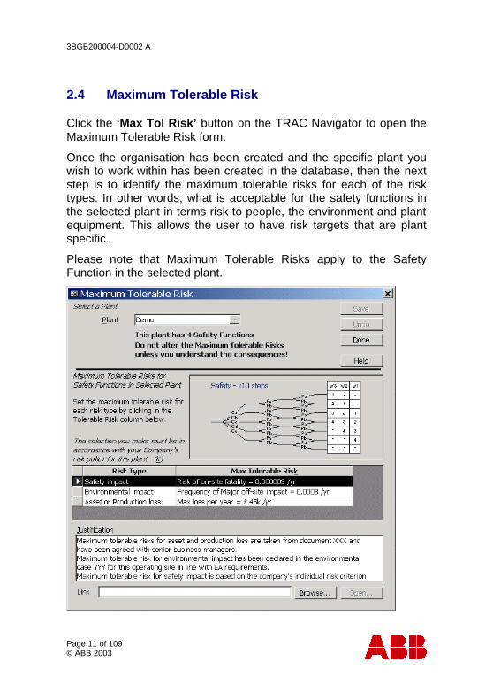
2.4 Maximum Tolerable Risk
Click the ‘Max Tol Risk’ button on the TRAC Navigator to open the Maximum Tolerable Risk form.
Once the organisation has been created and the specific plant you wish to work within has been created in the database, then the next step is to identify the maximum tolerable risks for each of the risk types. In other words, what is acceptable for the safety functions in the selected plant in terms risk to people, the environment and plant equipment. This allows the user to have risk targets that are plant specific.
Please note that Maximum Tolerable Risks apply to the Safety Function in the selected plant.
3BGB200004-D0002 A
Page 12 of 109 © ABB 2003
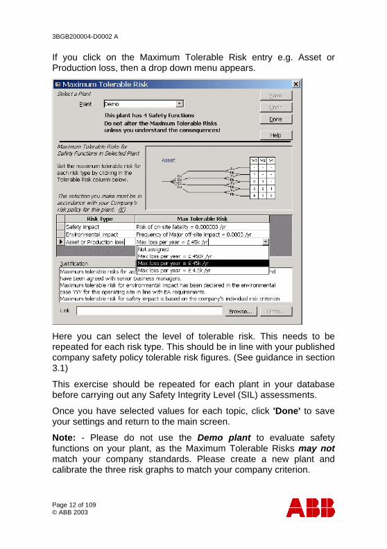
If you click on the Maximum Tolerable Risk entry e.g. Asset or Production loss, then a drop down menu appears.
Here you can select the level of tolerable risk. This needs to be repeated for each risk type. This should be in line with your published company safety policy tolerable risk figures. (See guidance in section 3.1)
This exercise should be repeated for each plant in your database before carrying out any Safety Integrity Level (SIL) assessments.
Once you have selected values for each topic, click 'Done' to save your settings and return to the main screen.
Note: - Please do not use the Demo plant to evaluate safety functions on your plant, as the Maximum Tolerable Risks may not match your company standards. Please create a new plant and calibrate the three risk graphs to match your company criterion.
3BGB200004-D0002 A
Page 13 of 109 © ABB 2003
2.5 Loop Template Library
This is where the I/O functions (which are used to create a safety function) are built up of individual components, either as input or output templates. One Template can be re-used many times in several different I/O functions. Hence, a common equipment configuration used on your plant, can be described in one template and then used to configure several safety functions on your plant. This should save you time in configuring TRAC.
Loop Templates can be used to build up into a library of standard components that can be re-used across many safety functions in your database.
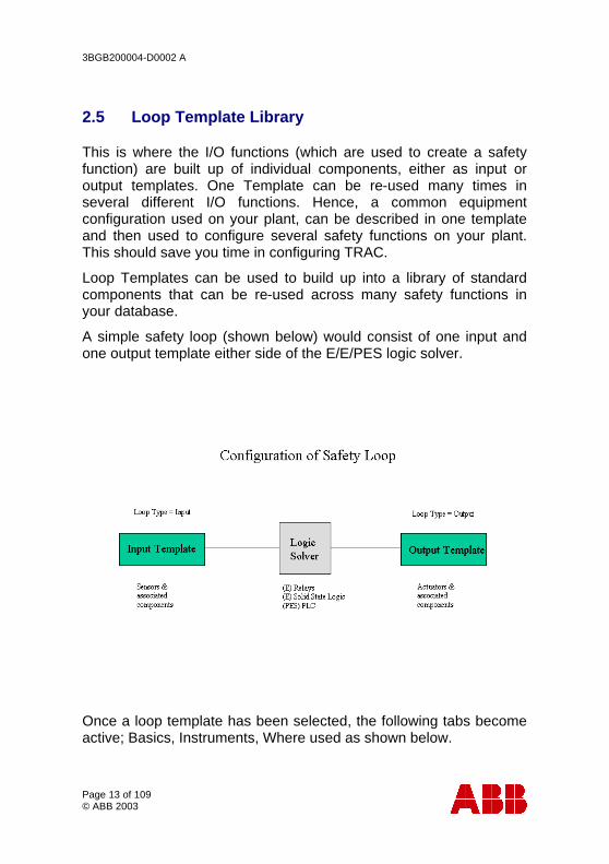
A simple safety loop (shown below) would consist of one input and one output template either side of the E/E/PES logic solver.
Once a loop template has been selected, the following tabs become active; Basics, Instruments, Where used as shown below.
3BGB200004-D0002 A
Page 14 of 109 © ABB 2003
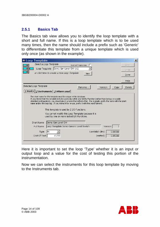
2.5.1 Basics Tab
The Basics tab view allows you to identify the loop template with a short and full name. If this is a loop template which is to be used many times, then the name should include a prefix such as 'Generic' to differentiate this template from a unique template which is used only once (as shown in the example).
Here it is important to set the loop 'Type' whether it is an input or output loop and a value for the cost of testing this portion of the instrumentation.
Now we can select the instruments for this loop template by moving to the Instruments tab.
3BGB200004-D0002 A
Page 15 of 109 © ABB 2003
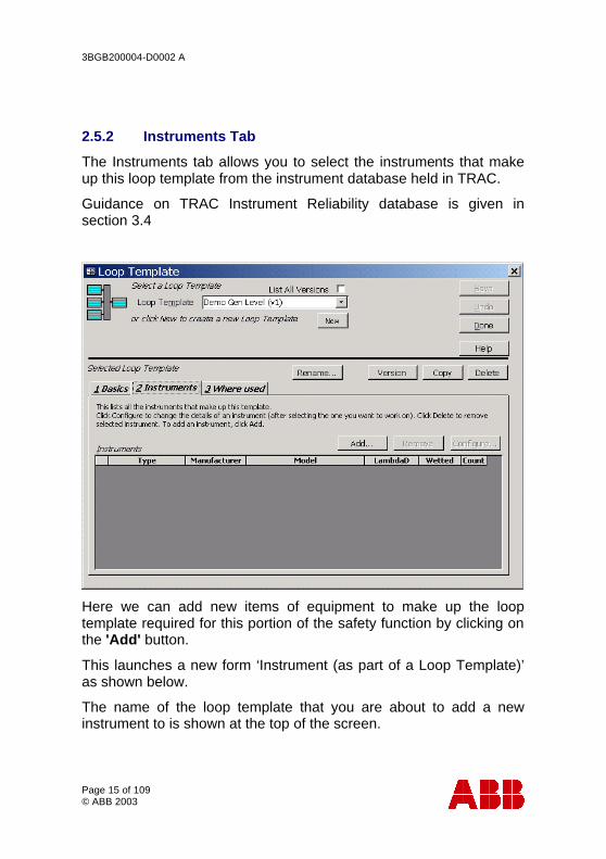
2.5.2 Instruments Tab
The Instruments tab allows you to select the instruments that make up this loop template from the instrument database held in TRAC.
Guidance on TRAC Instrument Reliability database is given in section 3.4
Here we can add new items of equipment to make up the loop template required for this portion of the safety function by clicking on the 'Add' button.
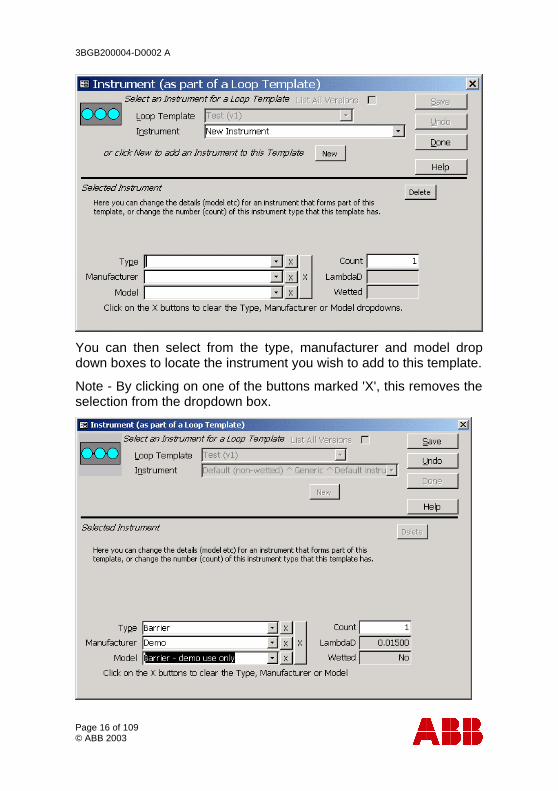
This launches a new form ‘Instrument (as part of a Loop Template)’ as shown below.
The name of the loop template that you are about to add a new instrument to is shown at the top of the screen.
3BGB200004-D0002 A
Page 16 of 109 © ABB 2003
You can then select from the type, manufacturer and model drop down boxes to locate the instrument you wish to add to this template.
Note - By clicking on one of the buttons marked 'X', this removes the selection from the dropdown box.
3BGB200004-D0002 A
Page 17 of 109 © ABB 2003
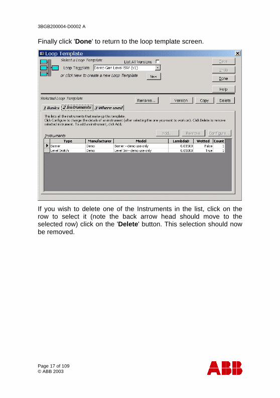
Finally click 'Done' to return to the loop template screen.
If you wish to delete one of the Instruments in the list, click on the row to select it (note the back arrow head should move to the selected row) click on the 'Delete' button. This selection should now be removed.
3BGB200004-D0002 A
Page 18 of 109 © ABB 2003
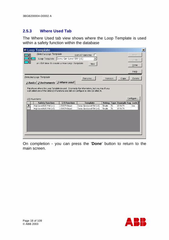
2.5.3 Where Used Tab
The Where Used tab view shows where the Loop Template is used within a safety function within the database
On completion - you can press the 'Done' button to return to the main screen.

3BGB200004-D0002 A
Page 19 of 109 © ABB 2003
2.6 Safety Function
Click the ‘Safety Function’ button on the TRAC Navigator to open the Safety Function form.
This is where the key information for your safety functions is held. Here you can carry out an assessment of the risk, configure your safety loop using equipment details held in the database, and see if your safety loop meets the requirements of your assessment.
First of all, you must select the plant you are considering from the drop down list. Then you can either create a new safety function by clicking the ‘New’ button, or view an existing safety function again by selecting this from the drop down list.
3BGB200004-D0002 A
Page 20 of 109 © ABB 2003
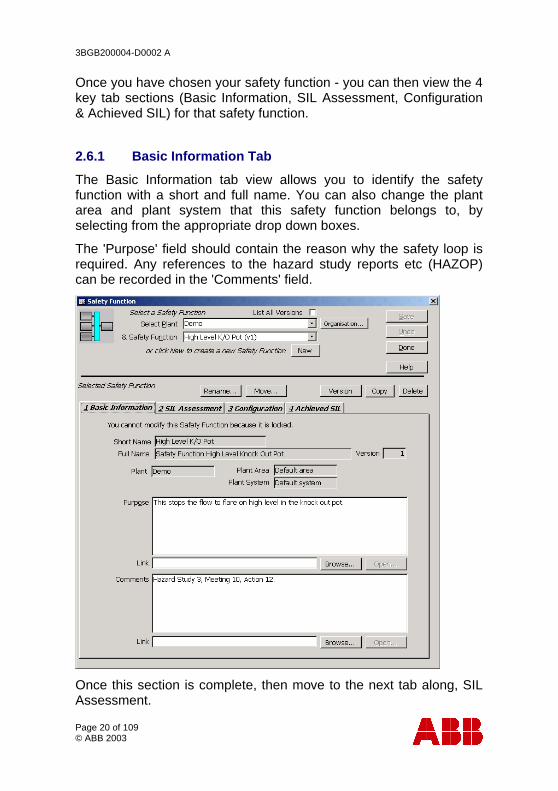
Once you have chosen your safety function - you can then view the 4 key tab sections (Basic Information, SIL Assessment, Configuration & Achieved SIL) for that safety function.
2.6.1 Basic Information Tab
The Basic Information tab view allows you to identify the safety function with a short and full name. You can also change the plant area and plant system that this safety function belongs to, by selecting from the appropriate drop down boxes.
The 'Purpose' field should contain the reason why the safety loop is required. Any references to the hazard study reports etc (HAZOP) can be recorded in the 'Comments' field.
Once this section is complete, then move to the next tab along, SIL Assessment.
3BGB200004-D0002 A
Page 21 of 109 © ABB 2003
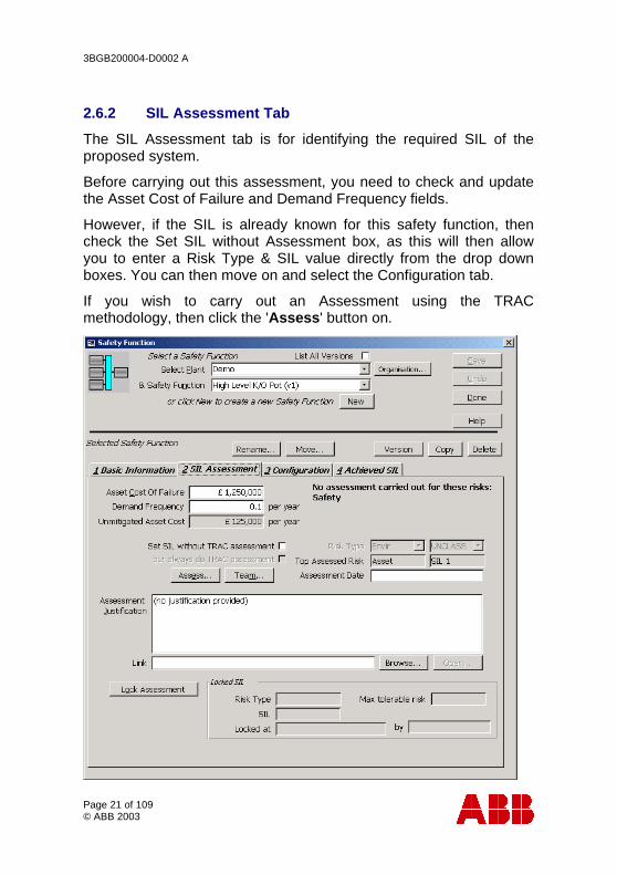
2.6.2 SIL Assessment Tab
The SIL Assessment tab is for identifying the required SIL of the proposed system.
Before carrying out this assessment, you need to check and update the Asset Cost of Failure and Demand Frequency fields.
However, if the SIL is already known for this safety function, then check the Set SIL without Assessment box, as this will then allow you to enter a Risk Type & SIL value directly from the drop down boxes. You can then move on and select the Configuration tab.
If you wish to carry out an Assessment using the TRAC methodology, then click the 'Assess' button on.
3BGB200004-D0002 A
Page 22 of 109 © ABB 2003
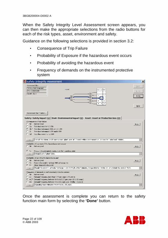
When the Safety Integrity Level Assessment screen appears, you can then make the appropriate selections from the radio buttons for each of the risk types, asset, environment and safety.
Guidance on the following selections is provided in section 3.2:
• Consequence of Trip Failure
• Probability of Exposure if the hazardous event occurs
• Probability of avoiding the hazardous event
• Frequency of demands on the instrumented protective system
Once the assessment is complete you can return to the safety function main form by selecting the ‘Done’ button.

3BGB200004-D0002 A
Page 23 of 109 © ABB 2003
A team who fully understands the plant should carry out this assessment activity. Click the 'Team' button (on the Safety Function form) to open the form shown below, where you can record the names and roles of those present during this assessment activity.
Once the details of the team members have been completed you can then return to the safety function main form by clicking the ‘Done’ button.
3BGB200004-D0002 A
Page 24 of 109 © ABB 2003
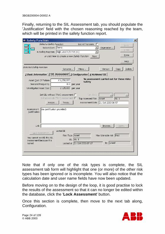
Finally, returning to the SIL Assessment tab, you should populate the 'Justification' field with the chosen reasoning reached by the team, which will be printed in the safety function report.
Note that if only one of the risk types is complete, the SIL assessment tab form will highlight that one (or more) of the other risk types has been ignored or is incomplete. You will also notice that the calculation date and user name fields have now been updated.
Before moving on to the design of the loop, it is good practise to lock the results of the assessment so that it can no longer be edited within the database, click the 'Lock Assessment' button.
Once this section is complete, then move to the next tab along, Configuration.
3BGB200004-D0002 A
Page 25 of 109 © ABB 2003
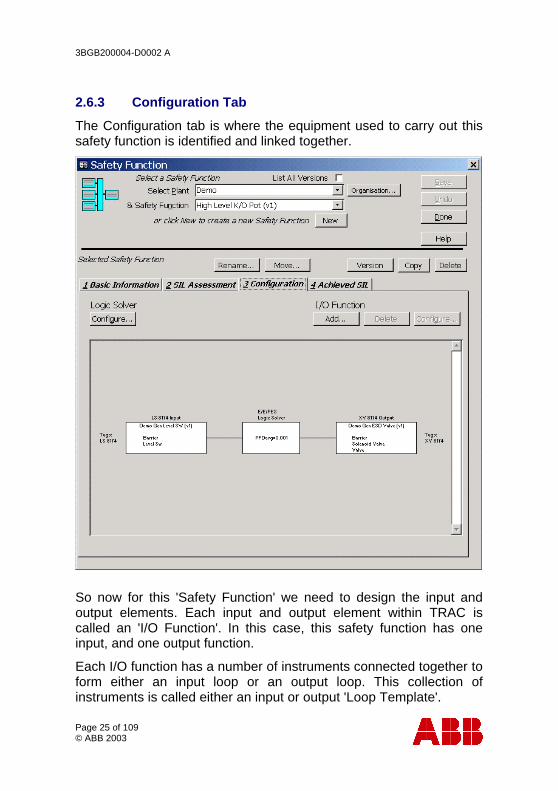
2.6.3 Configuration Tab
The Configuration tab is where the equipment used to carry out this safety function is identified and linked together.
So now for this 'Safety Function' we need to design the input and output elements. Each input and output element within TRAC is called an 'I/O Function'. In this case, this safety function has one input, and one output function.
Each I/O function has a number of instruments connected together to form either an input loop or an output loop. This collection of instruments is called either an input or output 'Loop Template'.
3BGB200004-D0002 A
Page 26 of 109 © ABB 2003
Click 'Add' to create a new I/O Function for this safety function.
(Note - if the safety function you have selected is 'locked', you will not be able to add/delete or configure any data. Please use the 'Version' button to create an 'unlocked' copy of this safety function.)
If you wish to delete one of the I/O Functions shown, click on the function in the graphic (note the I/O function will now turns grey to indicate that it has been selected) now click the 'Delete' button. This selection should now be removed.
To edit an existing I/O Function select the graphic by clicking on it once and click the I/O Function 'Configure' button, or simply double click. This brings up the I/O Function form.
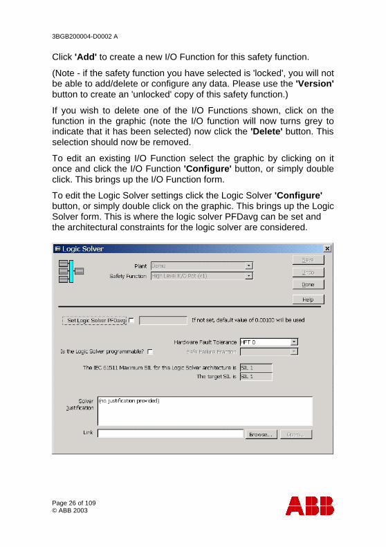
To edit the Logic Solver settings click the Logic Solver 'Configure' button, or simply double click on the graphic. This brings up the Logic Solver form. This is where the logic solver PFDavg can be set and the architectural constraints for the logic solver are considered.
3BGB200004-D0002 A
Page 27 of 109 © ABB 2003
2.6.4 I/O - Input/Output Function
I/O Functions are used to describe how the loop templates are connected together to define your safety function.
A safety function must have at least one input and one output template, and can have many input and output templates.
For the safety function to operate successfully, all I/O Functions must operate correctly. Each I/O Function can be configured with voting in TRAC.
To demonstrate how I/O functions work, we will consider an input function.
Please create a new (by clicking the 'New' button) or select an existing I/O function from the drop down box. Once an I/O function has been selected, the following tabs can be viewed; Definition, Factors & Tags.
3BGB200004-D0002 A
Page 28 of 109 © ABB 2003
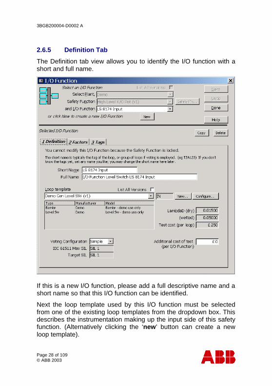
2.6.5 Definition Tab
The Definition tab view allows you to identify the I/O function with a short and full name.
If this is a new I/O function, please add a full descriptive name and a short name so that this I/O function can be identified.
Next the loop template used by this I/O function must be selected from one of the existing loop templates from the dropdown box. This describes the instrumentation making up the input side of this safety function. (Alternatively clicking the ‘new’ button can create a new loop template).

3BGB200004-D0002 A
Page 29 of 109 © ABB 2003
Note - The selection of generic loop templates comes in handy when you have to repeat a large number of similar design systems. These are then held in the ‘Loop Library’ for future reference.
If the loop template you desire is not within the current drop down list or you wish to modify an existing template, then click the 'configure' or ‘new’ button. TRAC will then display the loop template library form. (See section 2.5).
The voting configuration for this I/O function can be selected from the dropdown box. From this, the loop architecture can be calculated (using IEC 61511) and this can be compared against the target SIL from the SIL Assessment for this safety function.
Once this section is complete, then move to the next tab along, Factors.
3BGB200004-D0002 A
Page 30 of 109 © ABB 2003
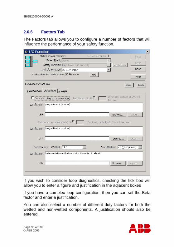
2.6.6 Factors Tab
The Factors tab allows you to configure a number of factors that will influence the performance of your safety function.
If you wish to consider loop diagnostics, checking the tick box will allow you to enter a figure and justification in the adjacent boxes
If you have a complex loop configuration, then you can set the Beta factor and enter a justification.
You can also select a number of different duty factors for both the wetted and non-wetted components. A justification should also be entered.
3BGB200004-D0002 A
Page 31 of 109 © ABB 2003
Guidance on the selection of these factors is given in section 3.3.
Once this section is complete, then move to the next tab along, Tags.
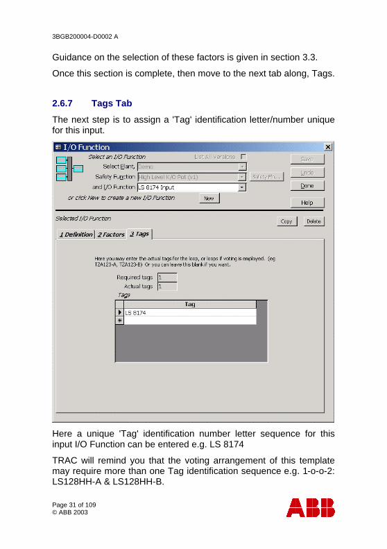
2.6.7 Tags Tab
The next step is to assign a 'Tag' identification letter/number unique for this input.
Here a unique 'Tag' identification number letter sequence for this input I/O Function can be entered e.g. LS 8174
TRAC will remind you that the voting arrangement of this template may require more than one Tag identification sequence e.g. 1-o-o-2: LS128HH-A & LS128HH-B.
3BGB200004-D0002 A
Page 32 of 109 © ABB 2003
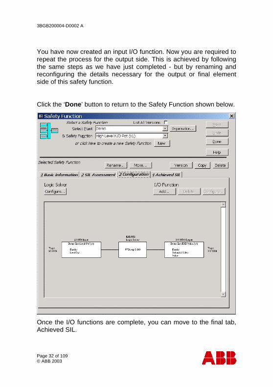
You have now created an input I/O function. Now you are required to repeat the process for the output side. This is achieved by following the same steps as we have just completed - but by renaming and reconfiguring the details necessary for the output or final element side of this safety function.
Click the ‘Done’ button to return to the Safety Function shown below.
Once the I/O functions are complete, you can move to the final tab, Achieved SIL.
3BGB200004-D0002 A
Page 33 of 109 © ABB 2003
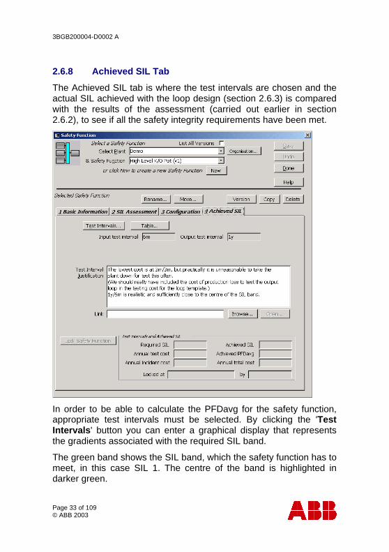
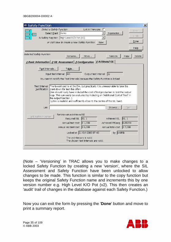
2.6.8 Achieved SIL Tab
The Achieved SIL tab is where the test intervals are chosen and the actual SIL achieved with the loop design (section 2.6.3) is compared with the results of the assessment (carried out earlier in section 2.6.2), to see if all the safety integrity requirements have been met.
In order to be able to calculate the PFDavg for the safety function, appropriate test intervals must be selected. By clicking the 'Test Intervals' button you can enter a graphical display that represents the gradients associated with the required SIL band.
The green band shows the SIL band, which the safety function has to meet, in this case SIL 1. The centre of the band is highlighted in darker green.

3BGB200004-D0002 A
Page 34 of 109 © ABB 2003
The areas shaded out indicate that the minimum test interval constraints for demand rate and mean time to dangerous failure have not been met. It is strongly recommended that the shaded areas be avoided, as testing may not be frequent enough to show up any unrevealed faults before an incident occurs or the loop may not be sufficiently reliable.
The red square indicates the chosen cursor position and as the position is changed, the total, testing and failure annual costs are updated on the right hand side of the screen. You can select various solutions within the graph by clicking the mouse pointer into a chosen area. Here a red marker moves around with the pointer to advise you which portion of the grid is currently selected.
The blue square represents the position that TRAC would recommend for this loop. TRAC will select a default portion of the graph based on the optimum test interval and overall cost of failure.
Once happy with the selection, you can return to the achieved SIL tab by clicking the ‘Done’ button.
The results for this safety function are then displayed; Required SIL, Achieved SIL, Achieved PFDavg, Annual Test Cost, Annual Incident Cost & Total Annual Cost.
Once you are satisfied that the design of the safety function is complete, it is good practise to lock the results in the database so that it can no longer be edited, click the 'Lock Safety Function' button.
3BGB200004-D0002 A
Page 35 of 109 © ABB 2003
(Note – ‘Versioning’ in TRAC allows you to make changes to a locked Safety Function by creating a new 'version', where the SIL Assessment and Safety Function have been unlocked to allow changes to be made. This function is similar to the copy function but keeps the original Safety Function name and increments this by one version number e.g. High Level K/O Pot (v2). This then creates an 'audit' trail of changes in the database against each Safety Function.)
Now you can exit the form by pressing the 'Done' button and move to print a summary report.
3BGB200004-D0002 A
Page 36 of 109 © ABB 2003
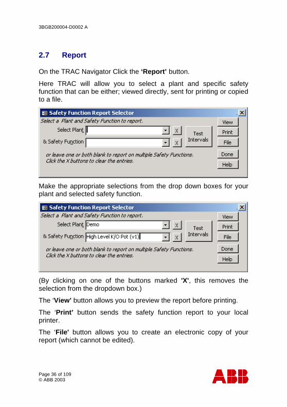
2.7 Report
On the TRAC Navigator Click the ‘Report’ button.
Here TRAC will allow you to select a plant and specific safety function that can be either; viewed directly, sent for printing or copied to a file.
Make the appropriate selections from the drop down boxes for your plant and selected safety function.
(By clicking on one of the buttons marked 'X', this removes the selection from the dropdown box.)
The ‘View’ button allows you to preview the report before printing.
The ‘Print’ button sends the safety function report to your local printer.
The ‘File' button allows you to create an electronic copy of your report (which cannot be edited).
3BGB200004-D0002 A
Page 37 of 109 © ABB 2003
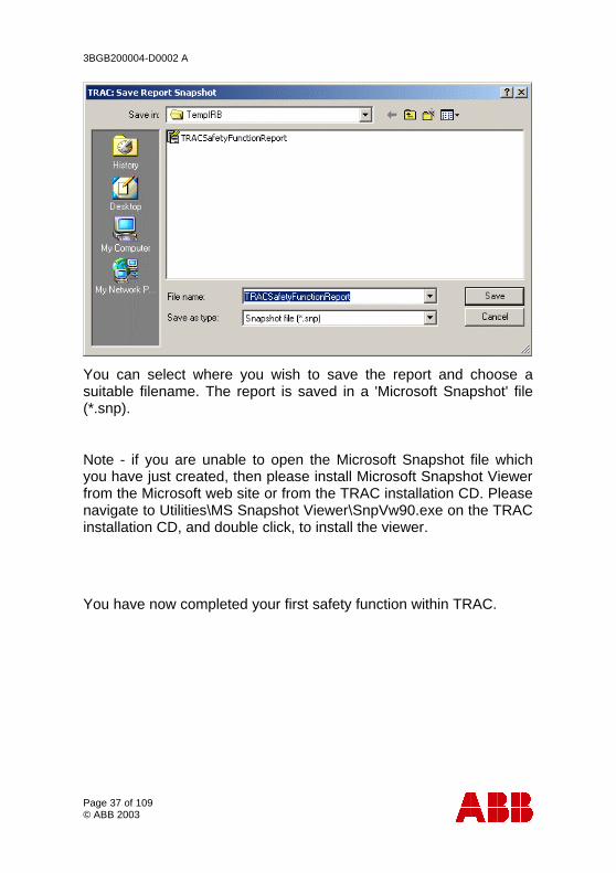
You can select where you wish to save the report and choose a suitable filename. The report is saved in a 'Microsoft Snapshot' file (*.snp).
Note - if you are unable to open the Microsoft Snapshot file which you have just created, then please install Microsoft Snapshot Viewer from the Microsoft web site or from the TRAC installation CD. Please navigate to Utilities\MS Snapshot Viewer\SnpVw90.exe on the TRAC installation CD, and double click, to install the viewer.
You have now completed your first safety function within TRAC.

3BGB200004-D0002 A
Page 38 of 109 © ABB 2003
3 TRAC User Guidance The following guidance is offered by ABB to help you decide on the key values that should be used within TRAC;
• Setting TRAC Maximum Tolerable Risks • Carrying out TRAC SIL Assessments • Selecting values for Input/Output Functions • TRAC Reliability Data
3.1 TRAC Maximum Tolerable Risk
3.1.1 Introduction
TRAC uses a simple risk graph approach to assessment of the appropriate Safety Integrity Level for an instrumented Safety Function. Before use, the risk graph needs aligning with the company safety policy. This is the responsibility of the company safety policy manager. It is suggested that a company risk policy document be produced by the manager. The justification box in TRAC under "Maximum Tolerable Risk" for each plant can refer to the document and indicate how the choice used in TRAC aligns with the policy.
3.1.2 Tolerable Risk
The term "Tolerable Risk" here is intended to indicate a level of risk associated with a safety function that permits the company overall to achieve its targets for safety, care of the environment and financial risk.
"Maximum Tolerable Risk" is the level of tolerable risk for a safety function that just permits the company overall to achieve its targets for safety, care of the environment and financial risk.
3BGB200004-D0002 A
Page 39 of 109 © ABB 2003
3.1.3 Safety Risk
Setting Maximum Tolerable Risk
The Maximum Tolerable Risk setting for Safety Risks determines the frequency for the Consequence " CD - Onsite Fatality" from each of the safety functions assessed for safety risk on the plant selected.
The current choices available are:
• Risk of on-site fatality = 0.0003 /yr.
• Risk of on-site fatality = 0.00003 /yr.
• Risk of on-site fatality = 0.000003 /yr.
Example
We can see the effect in the choice of risk setting by using an example.
If we have made the top selection, the frequency for the Consequence CD - "Risk of on-site fatality = 0.0003 /yr."
Consider, for example, a situation where the conditions for Exposure and Avoidance are as follows:
• "PB - Almost impossible to avoid"
• "FB - Frequent to permanent exposure in the hazardous zone"
These two selections imply that there will be no reduction in risk from these factors.
If we take the demand range W2 (0.3/yr. to 0.03/yr.) the highest demand rate within that range is 0.3/yr. We therefore require a risk reduction of 1000 to bring the frequency down to 0.0003/yr.
This is the risk reduction that needs to be provided by the Instrumented Trip System of being assessed. A requirement for risk reduction of 1000 means that we require at least SIL 3 to ensure this is achieved. This is the value that will be given by TRAC.
3BGB200004-D0002 A
Page 40 of 109 © ABB 2003
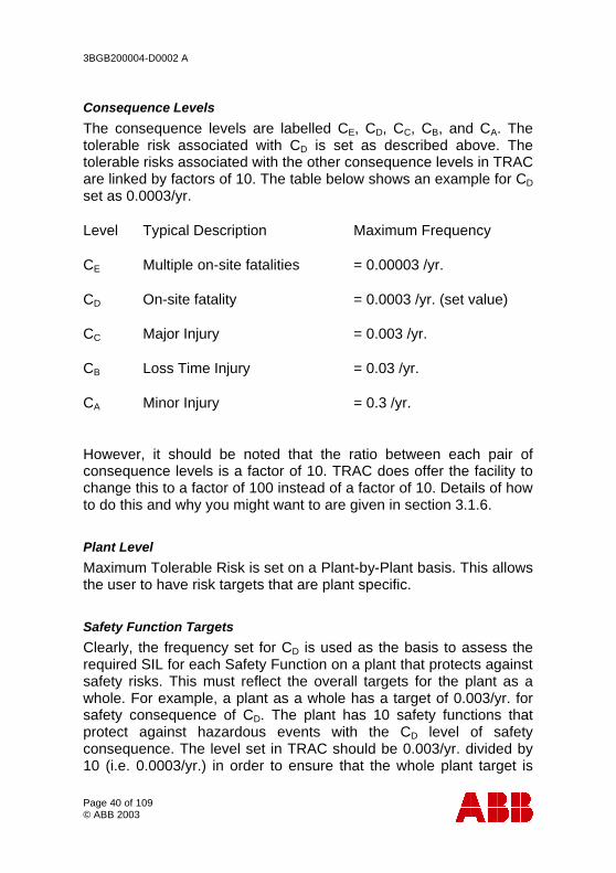
Consequence Levels
The consequence levels are labelled CE, CD, CC, CB, and CA. The tolerable risk associated with CD is set as described above. The tolerable risks associated with the other consequence levels in TRAC are linked by factors of 10. The table below shows an example for CD set as 0.0003/yr.
Level Typical Description Maximum Frequency
CE Multiple on-site fatalities = 0.00003 /yr.
CD On-site fatality = 0.0003 /yr. (set value)
CC Major Injury = 0.003 /yr.
CB Loss Time Injury = 0.03 /yr.
CA Minor Injury = 0.3 /yr.
However, it should be noted that the ratio between each pair of consequence levels is a factor of 10. TRAC does offer the facility to change this to a factor of 100 instead of a factor of 10. Details of how to do this and why you might want to are given in section 3.1.6.
Plant Level
Maximum Tolerable Risk is set on a Plant-by-Plant basis. This allows the user to have risk targets that are plant specific.
Safety Function Targets
Clearly, the frequency set for CD is used as the basis to assess the required SIL for each Safety Function on a plant that protects against safety risks. This must reflect the overall targets for the plant as a whole. For example, a plant as a whole has a target of 0.003/yr. for safety consequence of CD. The plant has 10 safety functions that protect against hazardous events with the CD level of safety consequence. The level set in TRAC should be 0.003/yr. divided by 10 (i.e. 0.0003/yr.) in order to ensure that the whole plant target is
3BGB200004-D0002 A
Page 41 of 109 © ABB 2003
met. Where there are a number of plants on a site, the target for a plant should be a realistic proportion of the target for the whole site.
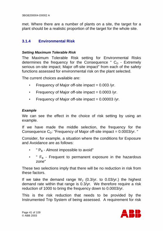
3.1.4 Environmental Risk
Setting Maximum Tolerable Risk
The Maximum Tolerable Risk setting for Environmental Risks determines the frequency for the Consequence " CD - Extremely serious on-site impact; Major off-site impact" from each of the safety functions assessed for environmental risk on the plant selected.
The current choices available are:
• Frequency of Major off-site impact = 0.003 /yr.
• Frequency of Major off-site impact = 0.0003 /yr.
• Frequency of Major off-site impact = 0.00003 /yr.
Example
We can see the effect in the choice of risk setting by using an example.
If we have made the middle selection, the frequency for the Consequence CD: "Frequency of Major off-site impact = 0.0003/yr. "
Consider, for example, a situation where the conditions for Exposure and Avoidance are as follows:
• " PB - Almost impossible to avoid"
• " FB - Frequent to permanent exposure in the hazardous zone"
These two selections imply that there will be no reduction in risk from these factors.
If we take the demand range W2 (0.3/yr. to 0.03/yr.) the highest demand rate within that range is 0.3/yr. We therefore require a risk reduction of 1000 to bring the frequency down to 0.0003/yr.
This is the risk reduction that needs to be provided by the Instrumented Trip System of being assessed. A requirement for risk
3BGB200004-D0002 A
Page 42 of 109 © ABB 2003
reduction of 1000 means that we require at least SIL 3 to ensure this is achieved. This is the value that will be given by TRAC.
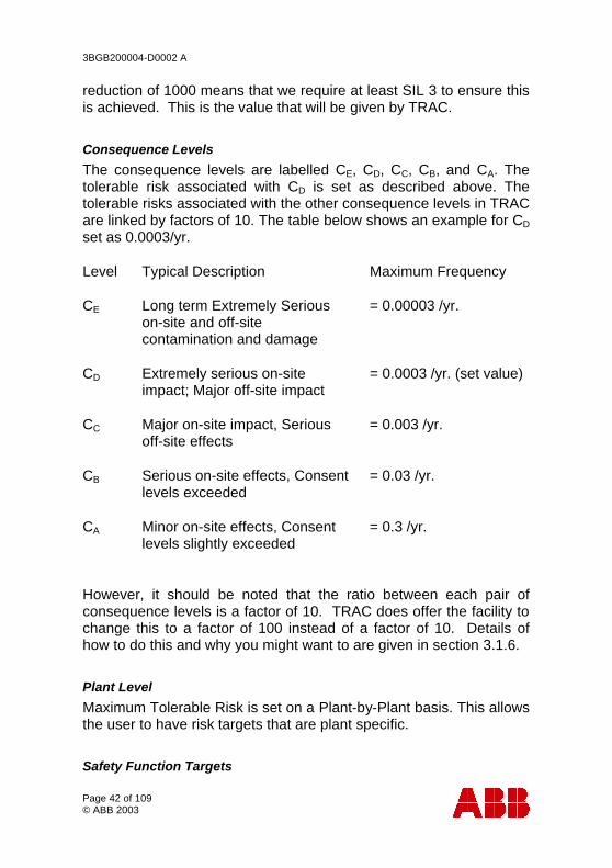
Consequence Levels
The consequence levels are labelled CE, CD, CC, CB, and CA. The tolerable risk associated with CD is set as described above. The tolerable risks associated with the other consequence levels in TRAC are linked by factors of 10. The table below shows an example for CD set as 0.0003/yr.
Level Typical Description Maximum Frequency
CE Long term Extremely Serious on-site and off-site contamination and damage
= 0.00003 /yr.
CD Extremely serious on-site impact; Major off-site impact
= 0.0003 /yr. (set value)
CC Major on-site impact, Serious off-site effects
= 0.003 /yr.
CB Serious on-site effects, Consent levels exceeded
= 0.03 /yr.
CA Minor on-site effects, Consent levels slightly exceeded
= 0.3 /yr.
However, it should be noted that the ratio between each pair of consequence levels is a factor of 10. TRAC does offer the facility to change this to a factor of 100 instead of a factor of 10. Details of how to do this and why you might want to are given in section 3.1.6.
Plant Level
Maximum Tolerable Risk is set on a Plant-by-Plant basis. This allows the user to have risk targets that are plant specific.
Safety Function Targets
3BGB200004-D0002 A
Page 43 of 109 © ABB 2003
Clearly, the frequency set for CD is used as the basis to assess the required SIL for each Safety Function on a plant that protects against environmental risks. This must reflect the overall targets for the plant as a whole. For example, a plant as a whole has a target of 0.003/yr. for environmental consequence of CD. The plant has 10 safety functions that protect against hazardous events with the CD level of environmental consequence. The level set in TRAC should be 0.003/yr. divided by 10 (i.e. 0.0003/yr.) in order to ensure that the whole plant target is met. Where there are a number of plants on a site, the target for a plant should be a realistic proportion of the target for the whole site.
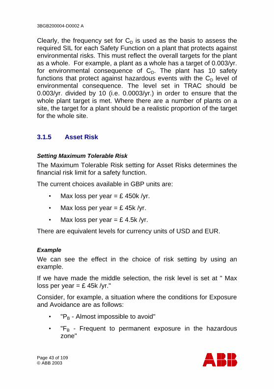
3.1.5 Asset Risk
Setting Maximum Tolerable Risk
The Maximum Tolerable Risk setting for Asset Risks determines the financial risk limit for a safety function.
The current choices available in GBP units are:
• Max loss per year = £ 450k /yr.
• Max loss per year = £ 45k /yr.
• Max loss per year = £ 4.5k /yr.
There are equivalent levels for currency units of USD and EUR.
Example
We can see the effect in the choice of risk setting by using an example.
If we have made the middle selection, the risk level is set at " Max loss per year = £ 45k /yr."
Consider, for example, a situation where the conditions for Exposure and Avoidance are as follows:
• "PB - Almost impossible to avoid"
• "FB - Frequent to permanent exposure in the hazardous zone"
3BGB200004-D0002 A
Page 44 of 109 © ABB 2003
These two selections imply that there will be no reduction in risk from these factors.
If we take the demand range W2 (0.3/yr. to 0.03/yr.) the highest demand rate within that range is 0.3/yr.
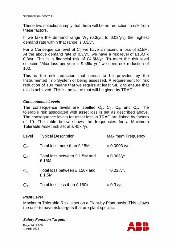
For a Consequence level of CC we have a maximum loss of £15M. At the above demand rate of 0.3/yr., we have a risk level of £15M x 0.3/yr. This is a financial risk of £4.5M/yr. To meet the risk level selected "Max loss per year = £ 45k/ yr." we need risk reduction of 100.
This is the risk reduction that needs to be provided by the Instrumented Trip System of being assessed. A requirement for risk reduction of 100 means that we require at least SIL 2 to ensure that this is achieved. This is the value that will be given by TRAC.
Consequence Levels
The consequence levels are labelled CD, CC, CB, and CA. The tolerable risk associated with asset loss is set as described above. The consequence levels for asset loss in TRAC are linked by factors of 10. The table below shows the frequencies for a Maximum Tolerable Asset risk set at £ 45k /yr.
Level Typical Description Maximum Frequency
CD Total loss more than £ 15M = 0.0003 /yr.
CC Total loss between £ 1.5M and £ 15M
= 0.003/yr
CB Total loss between £ 150k and £ 1.5M
= 0.03 /yr.
CA Total loss less than £ 150k = 0.3 /yr.
Plant Level
Maximum Tolerable Risk is set on a Plant-by-Plant basis. This allows the user to have risk targets that are plant specific.
Safety Function Targets
3BGB200004-D0002 A
Page 45 of 109 © ABB 2003
Clearly, the risk level set is used as the basis to assess the required SIL for each Safety Function on a plant. This must reflect the overall targets for the plant as a whole. For example, a plant as a whole has a target of £ 450k /yr. for asset risk. The plant has 10 safety functions that protect against hazardous events with asset loss as the consequence. The level set in TRAC should be £ 450k /yr. divided by 10 (i.e. £ 45k /yr.) in order to ensure that the whole plant target is met.
3.1.6 Setting Alternative Ratios - Safety & Environment
Purpose of Alternative Ratios
The purpose behind this option is to allow the user-company to align TRAC most closely to match the company risk targets. The tables given in the earlier sections of this document use factors of 10. TRAC allows the possibility to set either (or both) the safety or the environment consequence ratios to factors of 100 rather than 10.
Below are the similar tables for safety and environment using the factor of 100 setting. (Note the ratio between the lowest two consequences is unchanged.)
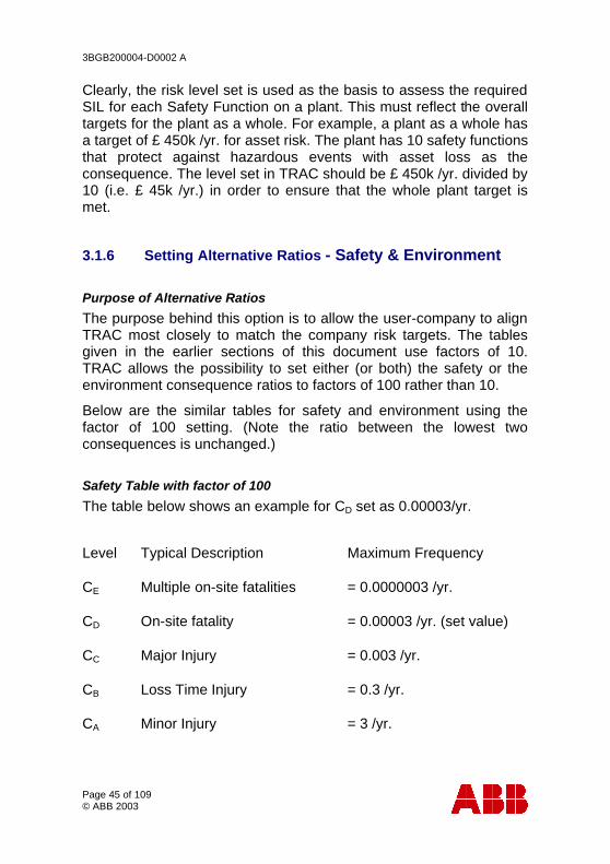
Safety Table with factor of 100
The table below shows an example for CD set as 0.00003/yr.
Level Typical Description Maximum Frequency
CE Multiple on-site fatalities = 0.0000003 /yr.
CD On-site fatality = 0.00003 /yr. (set value)
CC Major Injury = 0.003 /yr.
CB Loss Time Injury = 0.3 /yr.
CA Minor Injury = 3 /yr.

3BGB200004-D0002 A
Page 46 of 109 © ABB 2003
Environment Table with factor of 100
The table below shows an example for CD set as 0.00003/yr.
Level Typical Description Maximum Frequency
CE Long term Extremely Serious on-site and off-site contamination and damage.
= 0.0000003 /yr.
CD Extremely serious on-site impact; Major off-site impact.
= 0.00003 /yr. (set value)
CC Major on-site impact, Serious off-site effects
= 0.003 /yr.
CB Serious on-site effects, Consent levels exceeded.
= 0.3 /yr.
CA Minor on-site effects, Consent levels slightly exceeded.
= 3 /yr.
Selection Interface
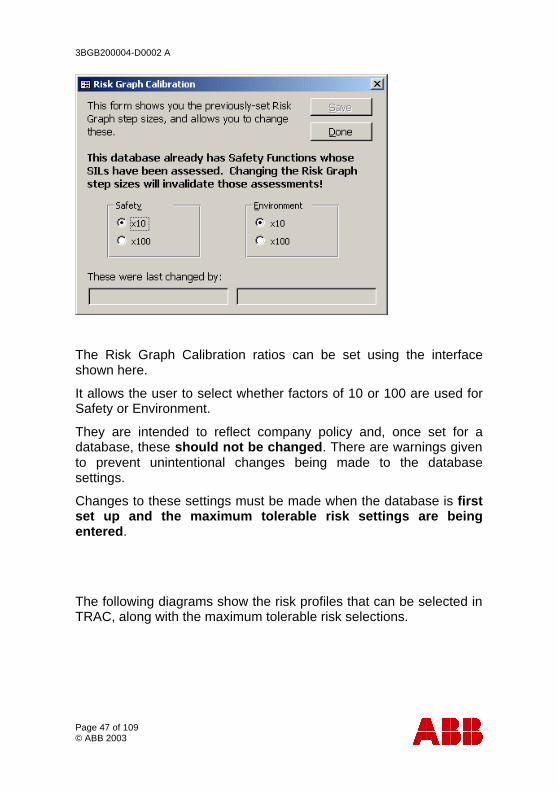
Select Tables\System\Risk Graph Calibration from the top menu to launch the Risk Graph Calibration form.
This form allows you to change the Risk Graph step sizes for Safety and Environment.
Changes to the Risk Graph settings must be made before any SIL assessments have been carried out i.e. when a database is first created.
3BGB200004-D0002 A
Page 47 of 109 © ABB 2003
The Risk Graph Calibration ratios can be set using the interface shown here.
It allows the user to select whether factors of 10 or 100 are used for Safety or Environment.
They are intended to reflect company policy and, once set for a database, these should not be changed. There are warnings given to prevent unintentional changes being made to the database settings.
Changes to these settings must be made when the database is first set up and the maximum tolerable risk settings are being entered.
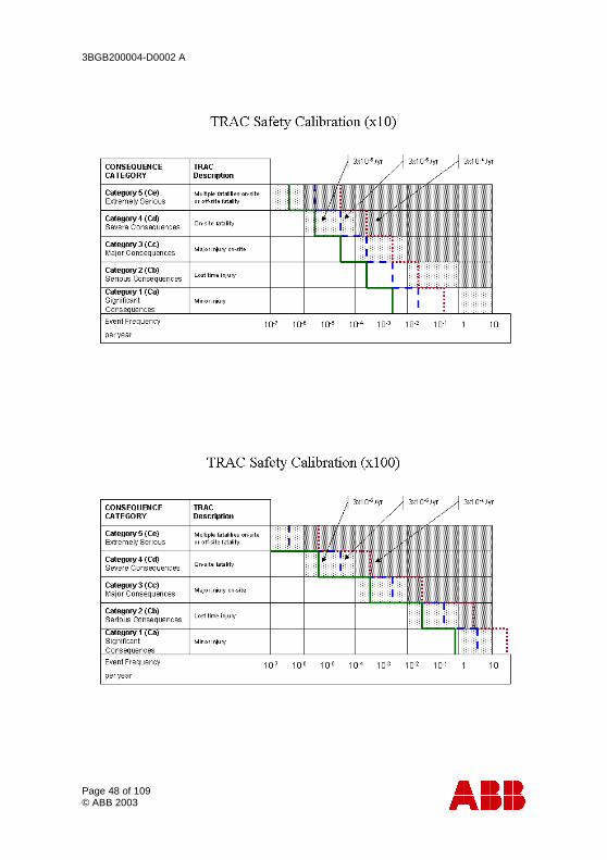
The following diagrams show the risk profiles that can be selected in TRAC, along with the maximum tolerable risk selections.
3BGB200004-D0002 A
Page 48 of 109 © ABB 2003
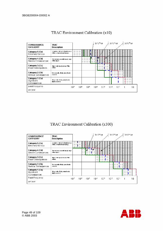
3BGB200004-D0002 A
Page 49 of 109 © ABB 2003
3BGB200004-D0002 A
Page 50 of 109 © ABB 2003
3.2 TRAC SIL Assessment
3.2.1 Probability of avoiding the hazardous event (PA or PB) Selection
There are two options under this heading on the TRAC SIL Assessment Form
• PA - Possible under certain conditions (credit claimed for risk reduction should be limited to a factor of 10 i.e. risk reduction is effective on 90% of occasions)
• PB - Almost impossible (no reduction in risk)
Great care should be exercised when selecting PA that the risk reduction claimed is not already included in the source of demand (usually the control system) or the trip system that is being assessed.
PA - should only be selected for operator involvement if all the following are true:
• facilities are provided to alert the operator that the protection has failed
• independent facilities are provided to shut down such that the hazard can be avoided or which enable all persons to escape to a safe area
• the time between the operator being alerted and a hazardous event occurring exceeds 30 minutes
Note: In this context, "independent" means "independent of the failed protective system" and also "independent of the sources of demand (e.g. failed control system)".
Factors which would prompt the selection of PB:
• operation of a unsupervised process (control room not continuously manned);
• hazardous event would develop quickly;
3BGB200004-D0002 A
Page 51 of 109 © ABB 2003
• danger not easily recognised by those at risk
• difficult to avoid the hazardous event (no effective escape routes available for the specific event)
PA - may be used to include risk reduction from passive protection means.
3.2.2 Probability of Exposure (FA or FB) Selection
This is only used for Safety Risks not for Environment or Asset. The Environment and Assets are assumed to be permanently exposed to risk from process hazards.
For safety risks, the Probability of Exposure in the hazardous zone (F) is calculated by determining the proportion of time when the area is occupied during a normal working period.
Notes:
If the time in the hazardous area is different, depending on the shift being operated then the maximum should be selected.
It is only appropriate to use FA where it can be shown that the demand rate is not related to times when occupancy could be higher than normal.
3.2.3 Consequence (C) Selection
During SIL Assessment the user is required to select a Consequence (C) from a table. There is a different table for Safety, Environment and Asset risk.
The choice should reflect a high likelihood that the consequence would be realised if none of the protective measures included in the SIL Assessment were effective.
3BGB200004-D0002 A
Page 52 of 109 © ABB 2003
3.2.4 Demand Frequency (W1, W2, W3) Selection
There are three demand rate options when carrying out SIL Assessments. (Default settings in TRAC).
These cover three ranges:
• W3 is 3 /yr. to 0.3/yr.
• W2 is 0.3 /yr. to 0.03/yr.
• W1 is above 0.03 /yr.
From experience, the failure rate for a specific demand cause will fall clearly into one of these ranges.
It is important that the range selected is consistent with the numeric demand frequency specified for the safety function under the "SIL Assessment Tab"

3BGB200004-D0002 A
Page 53 of 109 © ABB 2003
3.3 Input/Output (I/O) Function Factors
3.3.1 Duty Factor Selection
Each safety function has at least one input I/O function and one output I/O function. Each of these I/O functions is configured by the user when the safety function is created. Each I/O function comprises of instruments that are in contact the process fluid (wetted) and others that are not on contact with the process fluid (non-wetted). For each I/O function, two duty factors can be set: one for the wetted instruments and another for the non-wetted. The duty factor is used to increase the dangerous failure rate used by TRAC for calculation. A wetted duty factor of x1.5 on and input I/O function means that TRAC will take from the database the dangerous failure rate for the sensors in that loop and multiply that rate by 1.5. The wetted duty factor is used to reflect the effect process fluid on the reliability of the measurement. A heavy hydrocarbon or polymeric material that could block the impulse line of a pressure sensor might be described by a duty factor of x4. Less "difficult" materials can be covered by lower duty factors. The non-wetted duty factor is used in a similar to increase the failure rates for barriers, trip amplifiers, solenoid valves, etc. in a loop where they may be subject to vibration or other adverse environmental influences.
3BGB200004-D0002 A
Page 54 of 109 © ABB 2003
3.3.2 Diagnostic Coverage Selection
Simple instrumented systems have no means of detecting fail-to-danger faults; that is why they are tested at regular intervals. Some logic solvers have the capability to detect some types of fail-to-danger faults in I/O loops. If the logic solver can detect this type of fault, then the diagnostic coverage factor may be used to reflect this. The factor claimed (%) should be the proportion of fail-to-danger faults that can be detected AND be guaranteed to be corrected within a short enough period of time that the contribution to the PFDavg of the loop from the detected faults is negligible. This needs to be demonstrated before making the claim including consideration and contribution from human error.
3.3.3 Beta Factor Selection
Where the I/O function has a multi-channel voting arrangement (such as 1oo3) failure of that function requires failure of more than one channel be in a failed state. It is important to include the potential for dependent failure in any calculations. TRAC uses a Beta Factor model for inclusion of dependent (common mode or common cause) failure. If you have no knowledge of the potential for dependent failure in a multi-channel I/O Function then you are recommended to use the default beta factor of 15%. Assessment of the I/O Function and justification of some other beta factor requires specialist knowledge and understanding.
3BGB200004-D0002 A
Page 55 of 109 © ABB 2003
3.4 TRAC Reliability Data
3.4.1 Introduction
TRAC is provided with a database of generic instrument failure rate data. This allows the new user to carry out basic trip system reliability calculations using TRAC.
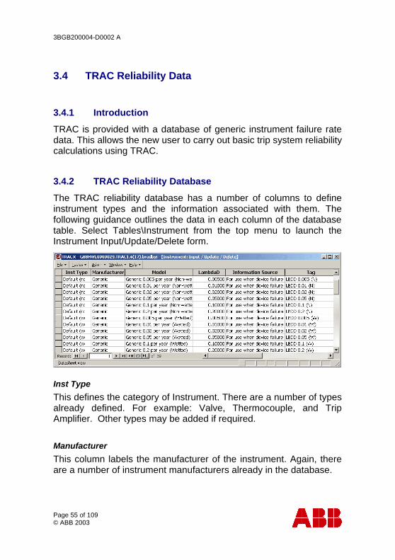
3.4.2 TRAC Reliability Database
The TRAC reliability database has a number of columns to define instrument types and the information associated with them. The following guidance outlines the data in each column of the database table. Select Tables\Instrument from the top menu to launch the Instrument Input/Update/Delete form.
Inst Type
This defines the category of Instrument. There are a number of types already defined. For example: Valve, Thermocouple, and Trip Amplifier. Other types may be added if required.
Manufacturer
This column labels the manufacturer of the instrument. Again, there are a number of instrument manufacturers already in the database.
3BGB200004-D0002 A
Page 56 of 109 © ABB 2003
Model
This defines the model of the instrument. Typically, this would be the appropriate model name and number. This is a free-form field and is not predefined.
LambdaD
This is the dangerous failure rate per year for the instrument. For an instrument used in a trip loop, this is the failure rate associated with failure of the trip to operate on demand. This will be a proportion of the total failure rate for the instrument.
Information Source
This is a free-form field in which to note the source of the failure data. This may be from another database, from site instrument failure records or from manufacturers. See important note below regarding manufacture sourced information.
Tag
This is a short-form field to identify the instrument and is only used internally within TRAC.
IsPredefined
Initially, this field is initially "True" for instrument data shipped with TRAC and is "False" for user-entered data.
3.4.3 New Data
New Data - where will it come from?
Most TRAC users will want to add new reliability data. This will be for a variety of reasons. These may include: (1) you have specialist instruments that are not already in the database (2) you have local failure rate information that you wish to add to the database to use as an alternative to the existing TRAC generic data.
3BGB200004-D0002 A
Page 57 of 109 © ABB 2003
A word of warning: manufacturers are not in a position to record failure data from field experience. Some will try to gauge the failure rate from complaints or returns; this will tend to be on the optimistic side. Others will try to look at quality control testing to gauge the failure rate. In general, this will not be as realistic as data from genuine field operation. This is especially true for applications where the process fluid has an influence on the failure rate; for example sensors and valves.
An exception would be electronic circuitry - assessment of this can be carried out using FMEA techniques and can provide a realistic assessment of reliability.
Dangerous Failures and Safe Failures
For safety function assessment, instrument failures can be broadly classed into two types: safe and dangerous. The distinction between these failure modes is best illustrated by consideration of a sensor in a single channel trip. Failure of the sensor such that it’s output spuriously operates the trip; this would be classed as a safe failure. The failure is revealed (by the trip operating).
An example of a dangerous failure would be where a solenoid valve is normally energised and seizes in that position. When the power is removed, the valve stays in the energised position. The dangerous failures for the solenoid valve would be this and others where it fails to respond on demand.
Dangerous Failure Rate (λD)
The key information used by TRAC is the dangerous failure rate for the instrument. This is the failure rate for the instrument when the failure mode is such that the safety function would not operate on demand if the instrument were the only one used for that safety function. The dangerous failure rate is designated by the symbol λD (Lambda D) and has units of "per year of use".
It is therefore important that the user is able to assess the dangerous failure rate from the data recorded for instrument failures on site.
3BGB200004-D0002 A
Page 58 of 109 © ABB 2003
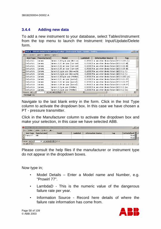
3.4.4 Adding new data
To add a new instrument to your database, select Tables\Instrument from the top menu to launch the Instrument: Input/Update/Delete form.
Navigate to the last blank entry in the form. Click in the Inst Type column to activate the dropdown box. In this case we have chosen a PT - pressure transmitter.
Click in the Manufacturer column to activate the dropdown box and make your selection, in this case we have selected ABB.
Please consult the help files if the manufacturer or instrument type do not appear in the dropdown boxes.
Now type in;
• Model Details – Enter a Model name and Number, e.g. "Prowirl 77".
• LambdaD - This is the numeric value of the dangerous failure rate per year.
• Information Source - Record here details of where the failure rate information has come from.
3BGB200004-D0002 A
Page 59 of 109 © ABB 2003
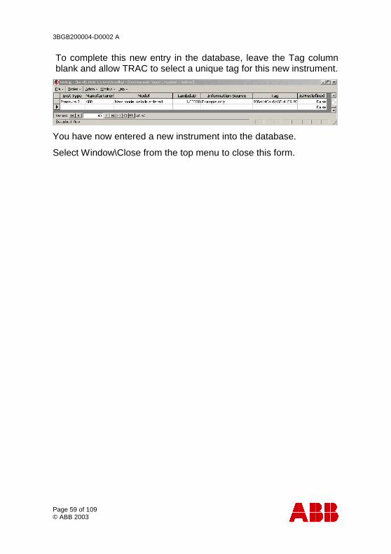
To complete this new entry in the database, leave the Tag column blank and allow TRAC to select a unique tag for this new instrument.
You have now entered a new instrument into the database.
Select Window\Close from the top menu to close this form.
3BGB200004-D0002 A
Page 60 of 109 © ABB 2003
4 TRAC Roles Roles for TRAC.
TRAC uses Microsoft SQL Server security to protect your data. The level of protection you implement will depend on the user group who need access to the information and your computer network.
The security barriers are:
• gaining access to a PC that has network access to the server
• login name and password control access to the server
• assignment of access for that login name to one or more databases
• the TRAC security profile and roles in the database
Passwords are used to stop login names being used by unauthorised people.
Each TRAC database user name can have one of three roles. When a new database is created for the first time, three login names are created with their associated database user names and roles.
• TRACReader - view data and run reports.
• TRACUser - as TRACReader, plus create and modify Safety Functions, perform backups.
• TRACOwner - as TRACUser, plus modify configuration data, create and delete databases, restore backups. Grant/revoke database access to logins created by the systems administrator.
Note: Do not modify configuration data unless directed to do so by ABB!
In addition there is the server role of:
• SystemsAdministrator (sa) - responsible for the computer environment, software upgrades and server security, creating/revoking server login accounts.
3BGB200004-D0002 A
Page 61 of 109 © ABB 2003
5 Frequently Asked Questions How do I configure TRAC to meet my needs?
There are many features in TRAC that allow the main tables to be reconfigured to your needs. However it is best to discuss and develop your specific requirements with the TRAC support team during the initial licence period as personal reconfiguration may lead to errors within your TRAC system.
How is TRAC supported and developed?
TRAC has been developed to meet the needs of people responsible for managing safety system determination and suitable designs.
Bugs and undesirable features are logged and corrected during further releases of the software. Suggestions for improvements are encouraged as part of the development plan. Contact TRAC support at ABB - see back page for contact details.
Do I need to start the server?
The TRAC server has to be started before the client can access the information. The server can be started automatically as part of the PC start up (eg if the database is used frequently by a variety of people) or manually from the windows start menu (eg if the database is used infrequently by a small number of people). Running a server does consume windows resources and therefore may slow down other software if there is not enough memory or disk space.
What is the server called?
Client PCs access the server PC using the network's name for the server PC. (A special case exists for the client PC being the same as the server PC where the name "(Local)" can be used).
I get an error when I try to access the server.
The computer network has to provide a route from the client to the server. If you get errors such as a general network error when trying to access the server, it is likely that the client is trying to use the wrong protocol to traverse this route. See section 13.3

3BGB200004-D0002 A
Page 62 of 109 © ABB 2003
What is the database called?
A database is given a name when it is created by a system owner (role TRAC Owner). The name needs to be published to all the users who want access to the data together with the server name.
What does the system administrator have to do?
The role of systems administrator is key to a secure, reliable database - both physical and software. The system administrator password gives complete access to the database structure, information and security. Therefore the choice of system administrator is very important and they should have the capabilities to manage the database in a way that reflects the importance of the information being handled. Immediately TRAC has been installed the systems administrator password should be changed, written down, and kept in a safe place (login name of "sa")
The system administrator is responsible for issuing login names and passwords.
What is Backup / Restore?
The information in TRAC is stored in a database that is attached to a server, whilst the data is stored in a file by the server on its local hard disk it must not be copied or moved directly. TRAC provides functionality to manage a comprehensive set of backups. These backups make data secure from corruption or loss due to problems with people, hardware and software. Backup copies of the data should be taken before and after any major information is changed or added. A backup file can be stored on a network drive and backed up to tape. See Help for more details.
Do I need a Licence to run TRAC?
To run the TRAC program you need to be issued with a key by the TRAC support desk. The key is only valid for a specific PC and therefore if you install the client software on 6 different PCs you will need 6 keys. The first time you open a database on a new PC you will be prompted to ring ABB and obtain a new key.
3BGB200004-D0002 A
Page 63 of 109 © ABB 2003
I've opened a 'spreadsheet' view on a table. How do I close it again?
Press Ctrl-F4, or choose Close from the Windows menu.
There are a large number of forms in TRAC that have no close button, mostly spreadsheet views in the Maintenance and System Menus. All can be closed by the Ctrl-F4 key, which is the standard Windows shortcut for closing a 'child' window.
I've opened several 'spreadsheet' views. How do I switch between them?
Use Ctrl-F6. This is the standard key assignment to switch windows in Microsoft Office products. (This will not work if you have reassigned shortcut keys in Office.)
Alternatively, select Next or Previous from the Windows menu.
I want to use TRAC for the first time - how do I gain access to database XYZ which is on server ABC?
1. Contact your system administrator for ABC and ask them to create a login account for you. When they have done this, they will tell you what password to use.
2. Contact the Database Owner for XYZ and ask them to grant you access to database XYZ. You will need to agree between yourselves what level of access is required, if Owner, User or Reader. You must tell them your login name but not the password.
3. Open the database. 4. Change your password.
How do I change my password?
1. Open any TRAC (or TRAMS) database. 2. Select Admin, Passwords from the menu bar. 3. Enter you existing password 4. Enter your new password the New Password field. 5. Re-enter this in the Confirmation field. 6. Press Set.
3BGB200004-D0002 A
Page 64 of 109 © ABB 2003
How do I change someone else's password?
Only the system administrator can do this.
The procedure is the same as changing your own password, but the Login Name list will contain a list of all logins on this server. Select the login whose password you want to change.
Alternatively, use Microsoft tools such as Enterprise Manager.
Help - I've forgotten my password?
1. Contact the system administrator and ask them to change it for you. They will tell you what your new password is.
2. Open any TRAC (or TRAMS) database. 3. Change your password to something you can remember.
Help - I've forgotten the sa password?
This is really bad news. Contact ABB for assistance.
How do I create new Server Login accounts?
Only the system administrator (sa) can do this.
1. Open any TRAC (or TRAMS) database as login sa. 2. Select Admin, Server Logins from the menu bar. 3. Enter your password, followed by tab or press Refresh. This
will produce a list of all current logins. 4. Click New. 5. Enter the name for the new login. If your company has a
standard for login names, you should follow this. 6. Click any roles you want to give the login.
Note: Do not grant Sysadmin or SecurityAdmin roles unless you understand the consequences!
7. Enter the password and confirmation. 8. Press Apply followed by Close. 9. The same form may be used to change the password or
change server roles, by selecting the login name and clicking Edit.
Alternatively, use Microsoft tools such as Enterprise Manager.
3BGB200004-D0002 A
Page 65 of 109 © ABB 2003
How do I delete a Server Login account?
Only the system administrator (sa) can do this.
1. Open any TRAC (or TRAMS) database as login sa. 2. Select Admin, Server Logins from the menu bar. 3. Enter your password, followed by tab or press Refresh. This
will produce a list of all current logins. 4. Select the login you want to delete. 5. Click on Delete.
You cannot delete a login if they are still a user in any database.
How do I grant access to a database?
You can only grant access to a database if you are the owner.
1. Open the TRAC database you want to give access to. 2. Select Admin, Database Users from the menu bar. 3. Enter your password, followed by tab or press Refresh. This
will produce a list of all current database users. 4. Click on New. 5. Enter the login name for the person you wish to grant access
to. (If you are system administrator you can select this from a list.)
6. Tab to the next field. This is the name the user will have in this database. By default it is the same as the login name; there is no good reason to change it.
7. Click on Owner, User or Reader to set up the user with the required access roles.
Note: Although you can individually select roles from the check boxes and list, this is not recommended.
8. Click Apply followed by Close. 9. The same form may be used to change the database roles
for a user, by selecting the user name and clicking Edit.
3BGB200004-D0002 A
Page 66 of 109 © ABB 2003
How do I revoke database access?
You can only revoke access to a database if you are the owner.
1. Open the TRAC database you want to revoke access to. 2. Select Admin, Database Users from the menu bar. 3. Enter your password, followed by tab or press Refresh. This
will produce a list of all current database users. 4. Select the user to be revoked. 5. Click on Delete.
Note: This does not revoke the server login. You may wish to ask the system administrator to do that.
3BGB200004-D0002 A
Page 67 of 109 © ABB 2003
6 System Requirements
• Computer / Processor - PC with Pentium 400 MHz or higher processor (1 GHz recommended)
• Memory - minimum 64 MB (96 MB recommended)
• Hard Disk - 200 MB for typical installation
• CD-ROM drive
• Display - 800 x 600 pixels or larger (1024 x 768 if large fonts selected) (1024 x 768 recommended)
• Operating System - Windows 95B, Windows 98, Windows ME, Windows 2000 Windows XP or NT4.
• Peripherals - Mouse
3BGB200004-D0002 A
Page 68 of 109 © ABB 2003
7 Overview of TRAC Installation What sort of installation will best meet your needs?
TRAC comes in two parts Client (TRAC) and Server (MSDE).
• The TRAC client is used to provide a user interface to manage and display data.
• The MSDE server holds the data on its hard disk and provides the client computer with useful packets of data. There can be many servers on a single network. The server has to be running for the data to be available ie databases that are to be shared should not be on portable computers or switched off for holidays!
There are three types of installation -
• single computer - both parts run on one computer,
• multiple clients - a single server supports multiple clients. This allows different PCs to access a common set of data.
• multiple server - this implies multiple clients and allows many databases to be managed independently but made available to a group of users.
A server can be installed on any PC; it does not necessarily need the client software to be installed on the same PC.
3BGB200004-D0002 A
Page 69 of 109 © ABB 2003
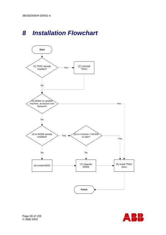
8 Installation Flowchart
Start
(1) TRAC alreadyinstalled?
(3) MSDE on anothermachine, accessed over
Network?
(2) UninstallTRAC
Yes
No
(8) Install TRACclient
Yes
No
(4) Is MSDE alreadyinstalled? Yes
(5) Is it Version 7.00.839or later?
Yes
No
(7) UpgradeMSDE
Finish
(6) Install MSDE
No
3BGB200004-D0002 A
Page 70 of 109 © ABB 2003
Notes:
1. You can check this by going to Control Panel, Add/Remove Programs, and looking for an entry called TRAC. (The name will have version numbers after it, eg TRAC 1.4 (18))
2. Uninstall TRAC by going to Control Panel, Add/Remove Programs, and selecting an entry called TRAC. (The name will have version numbers after it, eg TRAC 1.4 (18)) Then click on Add/Remove. This does NOT remove either MSDE or your database.
3. If you are going to locate the database on this PC, you need to install MSDE (on SQL Server 7) on this PC. See section 11 below for details.
4. You can check this by going to Control Panel, Add/Remove Programs, and looking for an entry called MSDE. Please note that MSDE must originally have been installed using Mixed Mode (Windows Authentication and SQL Server authentication).
5. Right-click the Service Manager icon on the taskbar, select About. The information displayed includes the version number.
6. Run setup.bat from the MSDE directory on the TRAC installation CD. See section 11 below for details.
7. This will upgrade MSDE (or SQL Server 7) to version 7.00.839. This is essential for TRAC. This step is now automatically carried out as part of the MSDE installation. See section 11 below for details.
8. Run setup.exe from the TRAC directory on the TRAC installation CD. See section 9 below for details.
3BGB200004-D0002 A
Page 71 of 109 © ABB 2003
9 How to Install a TRAC Client If TRAC is already installed, uninstall it first. See section 8 'Installation Flowchart'.
On each PC that will be used as a client -
1. Insert the TRAC CD into the CD drive on the PC. The TRAC menu system should autostart (if not double click on autorun.exe)
2. Navigate to 'Install TRAC Software (menu)'
3. Please read the instructions and then select 'Install TRAC Client Software'.
Notes:
When prompted by the software, we recommend that you do not over write existing system files with those from the TRAC CD; i.e. when prompted "Keep existing file?" respond "Yes".
If Microsoft Access 2000 is already installed on your PC, then please ensure that you have upgraded to Service Release 1 (SR-1) or TRAC will not run.
If you are using Windows NT, Windows 2000 or Windows XP, then the following permissions need to be set as a minimum. The ABB Eutech and ABBeutCIMlib directories security permissions - Read, Write, Execute and Delete for each person accessing TRAC.
On the first occasion that the TRAC client is launched, the software must be registered. Please refer to section 10, licensing TRAC.
If you are running TRAC as a network application, please refer to section 13 on how to configure your client.
3BGB200004-D0002 A
Page 72 of 109 © ABB 2003
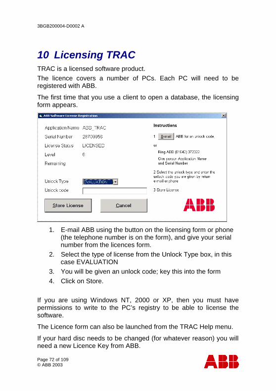
10 Licensing TRAC TRAC is a licensed software product. The licence covers a number of PCs. Each PC will need to be registered with ABB.
The first time that you use a client to open a database, the licensing form appears.
1. E-mail ABB using the button on the licensing form or phone (the telephone number is on the form), and give your serial number from the licences form.
2. Select the type of license from the Unlock Type box, in this case EVALUATION
3. You will be given an unlock code; key this into the form 4. Click on Store.
If you are using Windows NT, 2000 or XP, then you must have permissions to write to the PC’s registry to be able to license the software.
The Licence form can also be launched from the TRAC Help menu.
If your hard disc needs to be changed (for whatever reason) you will need a new Licence Key from ABB.
3BGB200004-D0002 A
Page 73 of 109 © ABB 2003
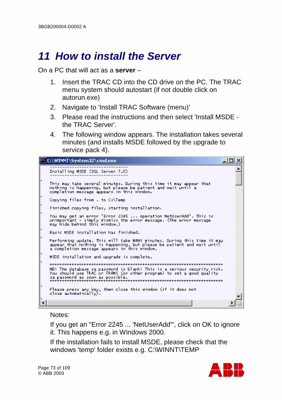
11 How to install the Server On a PC that will act as a server –
1. Insert the TRAC CD into the CD drive on the PC. The TRAC menu system should autostart (if not double click on autorun.exe)
2. Navigate to 'Install TRAC Software (menu)' 3. Please read the instructions and then select 'Install MSDE -
the TRAC Server'. 4. The following window appears. The installation takes several
minutes (and installs MSDE followed by the upgrade to service pack 4).
Notes: If you get an "Error 2245 ... 'NetUserAdd'", click on OK to ignore it. This happens e.g. in Windows 2000. If the installation fails to install MSDE, please check that the windows 'temp' folder exists e.g. C:\WINNT\TEMP
3BGB200004-D0002 A
Page 74 of 109 © ABB 2003
The TRAC Server software is now installed but there is no database and the standard 'sa' login created has no password.
A new database must be created on the server (to set up the standard TRAC logins) by launching the TRAC client software, see section 11.1 Please set a strong password for ‘sa’ and be careful not to forget it! You will need this password to administer TRAC. The passwords can be changed through Admin\Passwords form reached through the TRAC drop down menus. If you are running TRAC as a network application, please refer to section 12 on how to configure your server. Please note that MSDE, supplied as part of the TRAC installation, can only be used for TRAC & TRAMS databases. Your organisation must hold the appropriate Microsoft licenses to use MSDE for any other application databases.
11.1 Create a New Database
Please register your copy of TRAC as outlined in section 10.
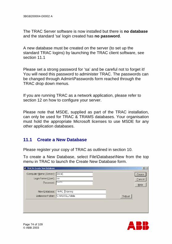
To create a New Database, select File\Database\New from the top menu in TRAC to launch the Create New Database form.
3BGB200004-D0002 A
Page 75 of 109 © ABB 2003
Ensure that the Computer Name (Server) is correctly entered for the server or enter ‘(local)’.
Type in your Login name ‘sa’ and password. (Password is initially blank unless you have reset the password.)
Type in a suitable New Database name you wish to give to the database, in this case 'TRAC_Training'.
To select the Database Folder where this new database will be held, click the 'Default' button. The Database folder (C:\MSSQL7\DATA) for TRAC databases should then appear in the Database Folder field.
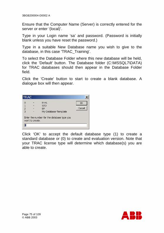
Click the 'Create' button to start to create a blank database. A dialogue box will then appear.
Click ‘OK’ to accept the default database type (1) to create a standard database or (0) to create and evaluation version. Note that your TRAC license type will determine which database(s) you are able to create.
3BGB200004-D0002 A
Page 76 of 109 © ABB 2003
12 Configuring the Server on your Network
This guidance is to help you set up a server PC on a network where the TRAC database(s) are run. This procedure should be carried out with the cooperation of your local IT department.
If you are running TRAC as a standalone package on one PC, then you do not need to follow these steps.
Notes:
If you are planning to use and existing SQL7 server, please ensure that the collating sequence and character set use the default settings. When a SQL7 server is installed it is irrevocably set up with a certain collating (sort) sequence and character set. A database backed up on one sort/charset cannot be restored to a database with different sort/charset. Providing you install MSDE from the standard installation kit, you always get the same sort/charset, but SQL7 installed by other means can be set up differently.
If you are planning to use an existing SQL7 server, please ensure that it has been configured with SQL Server Authentication.
12.1 Configure SQLserver Logon
If the server is running Windows NT, Windows 2000 or Windows XP, then the server must have a recognised network logon.
We recommend that a static password be chosen so that there is no need to update this password on a regular basis. Please ask your local IT department to create this network logon with a static password. This network logon also needs to be part of the Administrator's Group for the domain you are working in. (Control
3BGB200004-D0002 A
Page 77 of 109 © ABB 2003
Panel\Administrative Tools\Computer Management\System Tools\Local Users and Groups\Groups\Administrators). If you wish to restore database direct from a network drive, then the Logon must have mappings to the relevant network drives.
Please note that you will need the new network logon creating BEFORE you can proceed with the following steps.
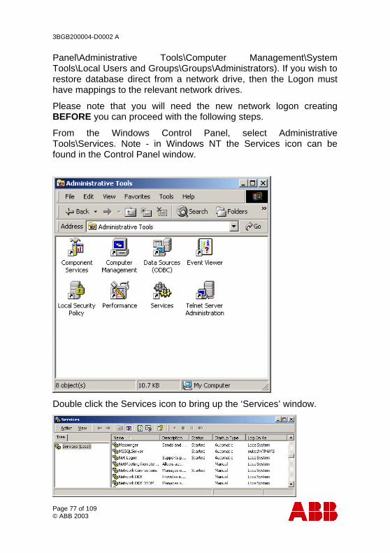
From the Windows Control Panel, select Administrative Tools\Services. Note - in Windows NT the Services icon can be found in the Control Panel window.
Double click the Services icon to bring up the ‘Services’ window.
3BGB200004-D0002 A
Page 78 of 109 © ABB 2003
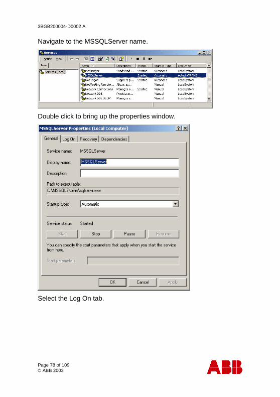
Navigate to the MSSQLServer name.
Double click to bring up the properties window.
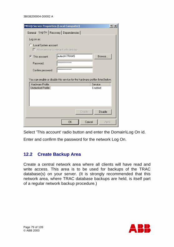
Select the Log On tab.
3BGB200004-D0002 A
Page 79 of 109 © ABB 2003
Select 'This account' radio button and enter the Domain\Log On id.
Enter and confirm the password for the network Log On.
12.2 Create Backup Area
Create a central network area where all clients will have read and write access. This area is to be used for backups of the TRAC database(s) on your server. (It is strongly recommended that this network area, where TRAC database backups are held, is itself part of a regular network backup procedure.)
3BGB200004-D0002 A
Page 80 of 109 © ABB 2003
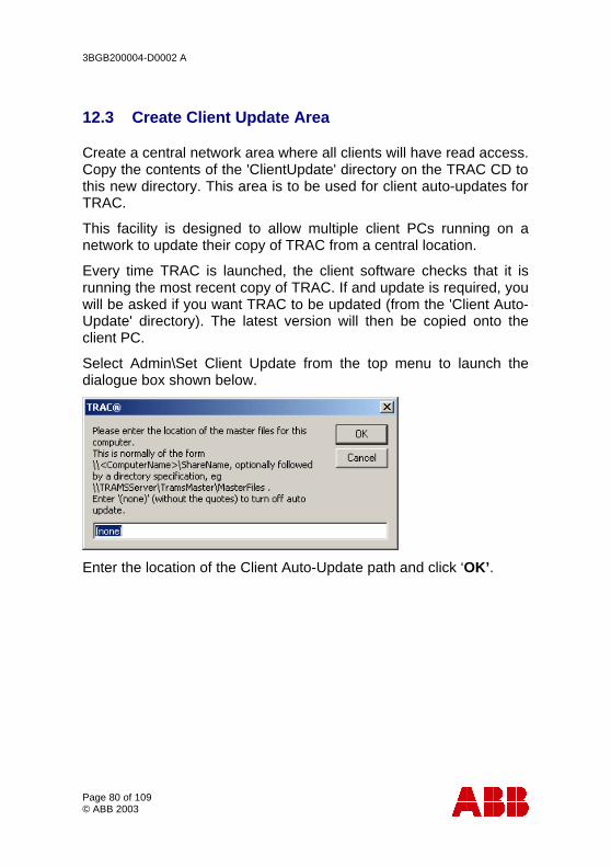
12.3 Create Client Update Area
Create a central network area where all clients will have read access. Copy the contents of the 'ClientUpdate' directory on the TRAC CD to this new directory. This area is to be used for client auto-updates for TRAC.
This facility is designed to allow multiple client PCs running on a network to update their copy of TRAC from a central location.
Every time TRAC is launched, the client software checks that it is running the most recent copy of TRAC. If and update is required, you will be asked if you want TRAC to be updated (from the 'Client Auto-Update' directory). The latest version will then be copied onto the client PC.
Select Admin\Set Client Update from the top menu to launch the dialogue box shown below.
Enter the location of the Client Auto-Update path and click ‘OK’.
3BGB200004-D0002 A
Page 81 of 109 © ABB 2003
13 Configuring a Client on your Network
This guidance is to help you set up a client PC on a network where a TRAC database is run on a central server.
The following steps need to be carried out by someone with System Administrator access once the server has been installed and configured as outlined in section 12.
If you are running TRAC as a standalone package on one PC, then you do not need to follow these steps.
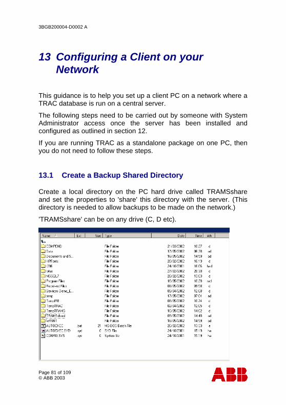
13.1 Create a Backup Shared Directory
Create a local directory on the PC hard drive called TRAMSshare and set the properties to 'share' this directory with the server. (This directory is needed to allow backups to be made on the network.)
'TRAMSshare' can be on any drive (C, D etc).

3BGB200004-D0002 A
Page 82 of 109 © ABB 2003
Right click on 'TRAMSshare' to bring up the properties window.
Select 'Share this folder' and click 'OK'.
Notice that the icon changes on the TRAMSshare folder to indicate that you have created an open share on this folder.
If you are using Windows NT, Windows 2000 or Windows XP, then the following permissions need to be set as a minimum:
• The TRAMSshare directory security permissions - Read, Write, Execute and Delete for the 'SQLserver login'
• The TRAMSshare directory share permissions - Read, Write, Execute and Delete for the 'SQLserver login'
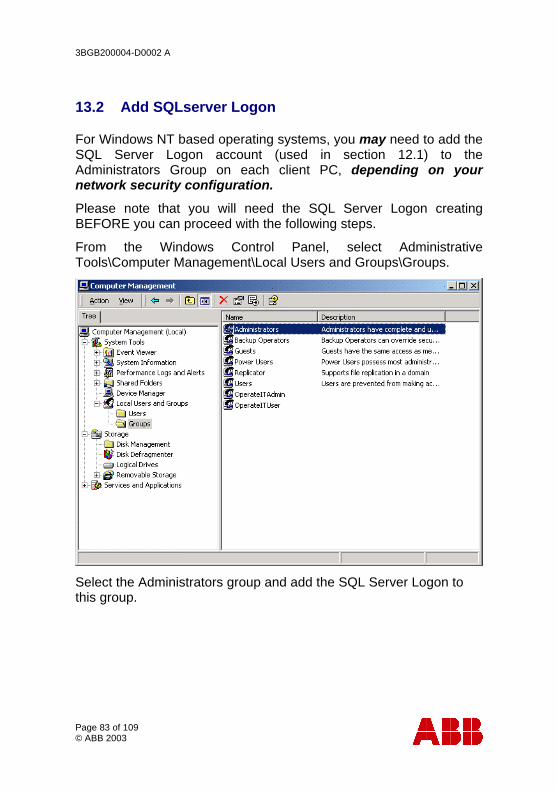
3BGB200004-D0002 A
Page 83 of 109 © ABB 2003
13.2 Add SQLserver Logon
For Windows NT based operating systems, you may need to add the SQL Server Logon account (used in section 12.1) to the Administrators Group on each client PC, depending on your network security configuration.
Please note that you will need the SQL Server Logon creating BEFORE you can proceed with the following steps.
From the Windows Control Panel, select Administrative Tools\Computer Management\Local Users and Groups\Groups.
Select the Administrators group and add the SQL Server Logon to this group.
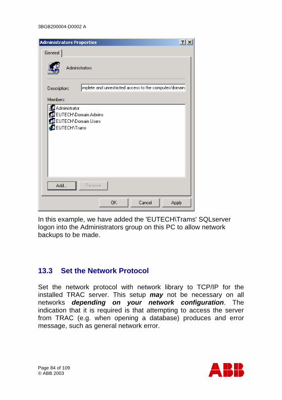
3BGB200004-D0002 A
Page 84 of 109 © ABB 2003
In this example, we have added the 'EUTECH\Trams' SQLserver logon into the Administrators group on this PC to allow network backups to be made.
13.3 Set the Network Protocol
Set the network protocol with network library to TCP/IP for the installed TRAC server. This setup may not be necessary on all networks depending on your network configuration. The indication that it is required is that attempting to access the server from TRAC (e.g. when opening a database) produces and error message, such as general network error.
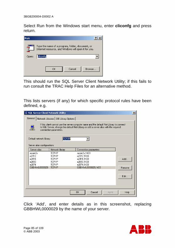
3BGB200004-D0002 A
Page 85 of 109 © ABB 2003
Select Run from the Windows start menu, enter cliconfg and press return.
This should run the SQL Server Client Network Utility; if this fails to run consult the TRAC Help Files for an alternative method.
This lists servers (if any) for which specific protocol rules have been defined, e.g.
Click ‘Add’, and enter details as in this screenshot, replacing GBBHWL0000029 by the name of your server.
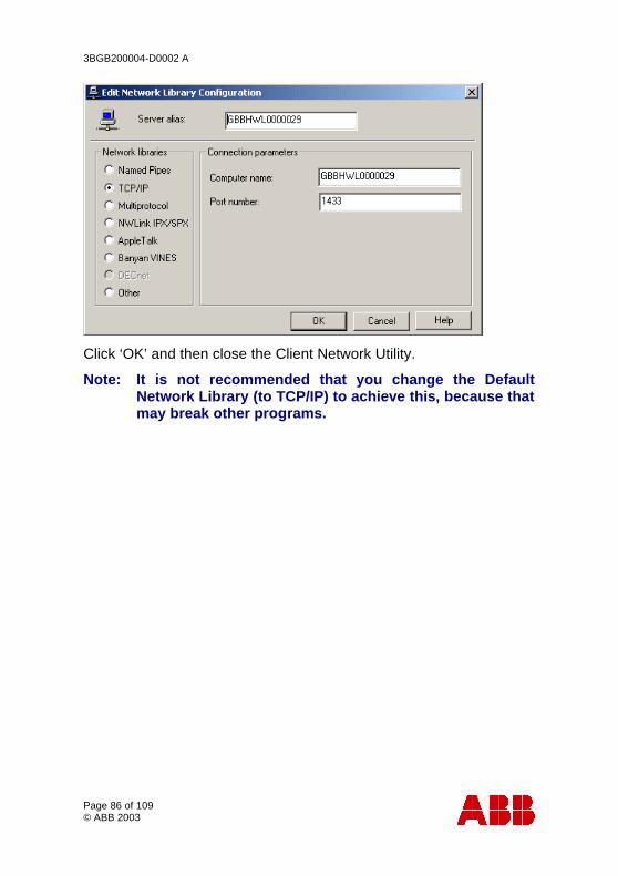
3BGB200004-D0002 A
Page 86 of 109 © ABB 2003
Click ‘OK’ and then close the Client Network Utility.
Note: It is not recommended that you change the Default Network Library (to TCP/IP) to achieve this, because that may break other programs.
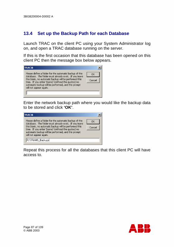
3BGB200004-D0002 A
Page 87 of 109 © ABB 2003
13.4 Set up the Backup Path for each Database
Launch TRAC on the client PC using your System Administrator log on, and open a TRAC database running on the server.
If this is the first occasion that this database has been opened on this client PC then the message box below appears.
Enter the network backup path where you would like the backup data to be stored and click ‘OK’.
Repeat this process for all the databases that this client PC will have access to.
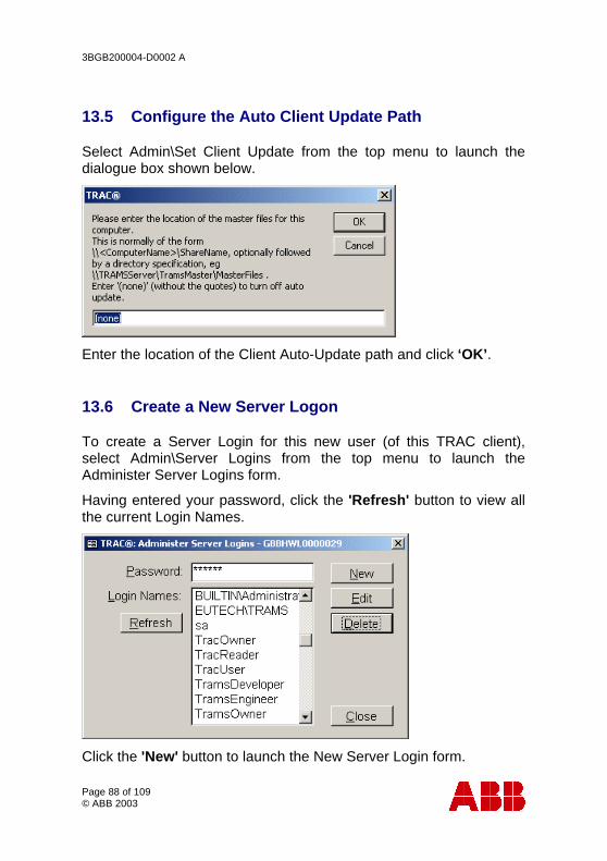
3BGB200004-D0002 A
Page 88 of 109 © ABB 2003
13.5 Configure the Auto Client Update Path
Select Admin\Set Client Update from the top menu to launch the dialogue box shown below.
Enter the location of the Client Auto-Update path and click ‘OK’.
13.6 Create a New Server Logon
To create a Server Login for this new user (of this TRAC client), select Admin\Server Logins from the top menu to launch the Administer Server Logins form.
Having entered your password, click the 'Refresh' button to view all the current Login Names.
Click the 'New' button to launch the New Server Login form.
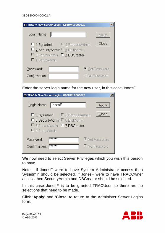
3BGB200004-D0002 A
Page 89 of 109 © ABB 2003
Enter the server login name for the new user, in this case JonesF.
We now need to select Server Privileges which you wish this person to have.
Note - If JonesF were to have System Administrator access then Sysadmin should be selected. If JonesF were to have TRACOwner access then SecurityAdmin and DBCreator should be selected.
In this case JonesF is to be granted TRACUser so there are no selections that need to be made.
Click 'Apply' and 'Close' to return to the Administer Server Logins form.
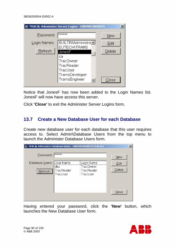
3BGB200004-D0002 A
Page 90 of 109 © ABB 2003
Notice that JonesF has now been added to the Login Names list. JonesF will now have access this server.
Click 'Close' to exit the Administer Server Logins form.
13.7 Create a New Database User for each Database
Create new database user for each database that this user requires access to. Select Admin\Database Users from the top menu to launch the Administer Database Users form.
Having entered your password, click the 'New' button, which launches the New Database User form.
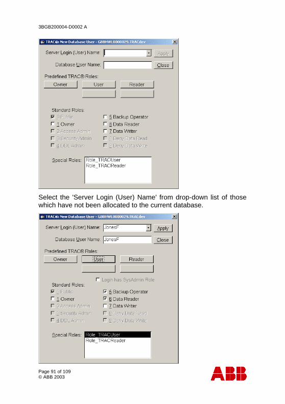
3BGB200004-D0002 A
Page 91 of 109 © ABB 2003
Select the 'Server Login (User) Name' from drop-down list of those which have not been allocated to the current database.
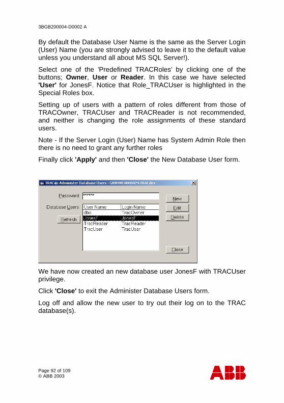
3BGB200004-D0002 A
Page 92 of 109 © ABB 2003
By default the Database User Name is the same as the Server Login (User) Name (you are strongly advised to leave it to the default value unless you understand all about MS SQL Server!).
Select one of the 'Predefined TRACRoles' by clicking one of the buttons; Owner, User or Reader. In this case we have selected 'User' for JonesF. Notice that Role_TRACUser is highlighted in the Special Roles box.
Setting up of users with a pattern of roles different from those of TRACOwner, TRACUser and TRACReader is not recommended, and neither is changing the role assignments of these standard users.
Note - If the Server Login (User) Name has System Admin Role then there is no need to grant any further roles
Finally click 'Apply' and then 'Close' the New Database User form.
We have now created an new database user JonesF with TRACUser privilege.
Click 'Close' to exit the Administer Database Users form.
Log off and allow the new user to try out their log on to the TRAC database(s).
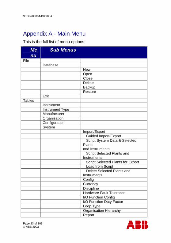
3BGB200004-D0002 A
Page 93 of 109 © ABB 2003
Appendix A - Main Menu This is the full list of menu options:
• Menu
• Sub Menus
File Database New Open Close Delete Backup Restore Exit Tables Instrument Instrument Type Manufacturer Organisation Configuration System Import/Export Guided Import/Export Script System Data & Selected
Plants and Instruments
Script Selected Plants and Instruments
Script Selected Plants for Export Load from Script Delete Selected Plants and
Instruments Config Currency Discipline Hardware Fault Tolerance I/O Function Config I/O Function Duty Factor Loop Type Organisation Hierarchy Report
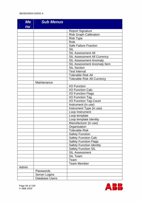
3BGB200004-D0002 A
Page 94 of 109 © ABB 2003
• Menu
• Sub Menus
Report Signature Risk Graph Calibration Risk Type Role Safe Failure Fraction SIL SIL Assessment All SIL Assessment All Currency SIL Assessment Anomaly SIL Assessment Anomaly Item SIL Section Test Interval Tolerable Risk All Tolerable Risk All Currency Maintenance I/O Function I/O Function Calc I/O Function Flags I/O Function Tag I/O Function Tag Count Instrument (in use) Instrument Type (in use) Loop Instrument Loop template Loop template Identity Manufacturer (in use) Organisation Tolerable Risk Safety Function Safety Function Calc Safety Function Flags Safety Function Identity Safety Function SIL SIL Assessment SIL Team Team Team Member Admin Passwords Server Logins Database Users
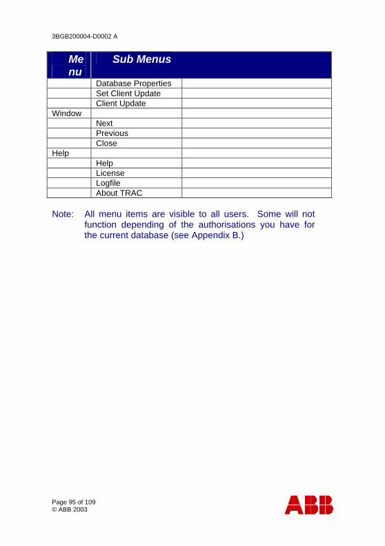
3BGB200004-D0002 A
Page 95 of 109 © ABB 2003
• Menu
• Sub Menus
Database Properties Set Client Update Client Update Window Next Previous Close Help Help License Logfile About TRAC Note: All menu items are visible to all users. Some will not
function depending of the authorisations you have for the current database (see Appendix B.)

3BGB200004-D0002 A
Page 96 of 109 © ABB 2003
Appendix B - Server and Database Security
Basics Security is implemented using SQL Server authentication. That is, the SQL Server is responsible for its own security, rather than using the services provided by any NT domain of which the user and server may be part of.
There are two aspects to security; gaining access to the SQL Server, and having done that, gaining access to databases on the server.
The Security Module SQL Server Login
This is the process of gaining access to the SQL Server, and requires a Login Name and Password.
When the server is installed, only the sa (system administrator) login exists. Although SQL Server allows the sa password to be blank, it is strongly recommended that this be changed to a strong password (see Appendix C - Strong Passwords), because sa has unlimited privileges for the server and for all databases on the server.
Note: In a networked environment, any machine on the network can gain access to any SQL Server running on any other machine on the network. With suitable tools, which include TRAC, a malicious person could damage the data in databases on that server, or damage the server installation itself, or create logins for unauthorised persons. The only protection against this is using strong passwords and keeping these secret. This is most important for the sa password.
The sa login account is then used to create user login accounts, for example using Enterprise Manager if available. In TRAC, the sa account is used to create the first TRAC database on the server. As part of this, TRAC creates a number of TRAC-specific logins, which are:
3BGB200004-D0002 A
Page 97 of 109 © ABB 2003
• TRACOwner
• TRACUser
• TRACReader
These all have an initial password of TRAC.
Note: It is strongly recommended that the passwords for the TRAC-specific logins are changed to at least moderately-strong passwords. This is particularly important for TRACOwner which has unlimited privileges in any TRAC database. (TRACReader at the other extreme has only read access and is much less critical.)
Each login account may be granted one or more server roles, which give the ability, for example, to make backups or create new databases. These are described in more detail in 'Server Roles' below.
Once the first TRAC database has been created, the sa account can be used within TRAC to create additional logins. Typically these would be name-based logins (eg huntjr), with strong passwords and used in preference to the default TRAC-specific logins. In that case the passwords for the TRAC-specific logins would not be made public.
Note: The TRACOwner login cannot be deleted so long as any TRAC database exists. The TRACUser and TRACReader logins can be deleted, but this is not recommended because they will be recreated every time a new TRAC database is created.
Server Roles
All server roles are predefined. The following are of interest to TRAC:
• Sysadmin
• SecurityAdmin
• DBCreator
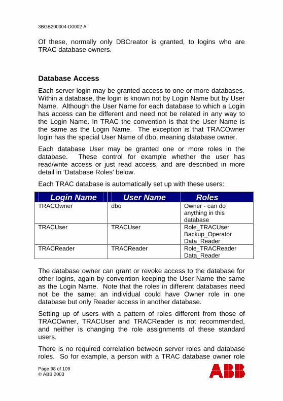
3BGB200004-D0002 A
Page 98 of 109 © ABB 2003
Of these, normally only DBCreator is granted, to logins who are TRAC database owners.
Database Access
Each server login may be granted access to one or more databases. Within a database, the login is known not by Login Name but by User Name. Although the User Name for each database to which a Login has access can be different and need not be related in any way to the Login Name. In TRAC the convention is that the User Name is the same as the Login Name. The exception is that TRACOwner login has the special User Name of dbo, meaning database owner.
Each database User may be granted one or more roles in the database. These control for example whether the user has read/write access or just read access, and are described in more detail in 'Database Roles' below.
Each TRAC database is automatically set up with these users:
• Login Name • User Name • Roles TRACOwner dbo Owner - can do
anything in this database
TRACUser TRACUser Role_TRACUser Backup_Operator Data_Reader
TRACReader TRACReader Role_TRACReader Data_Reader
The database owner can grant or revoke access to the database for other logins, again by convention keeping the User Name the same as the Login Name. Note that the roles in different databases need not be the same; an individual could have Owner role in one database but only Reader access in another database.
Setting up of users with a pattern of roles different from those of TRACOwner, TRACUser and TRACReader is not recommended, and neither is changing the role assignments of these standard users.
There is no required correlation between server roles and database roles. So for example, a person with a TRAC database owner role
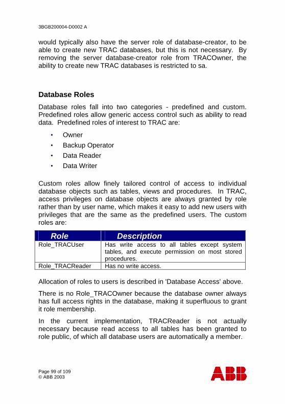
3BGB200004-D0002 A
Page 99 of 109 © ABB 2003
would typically also have the server role of database-creator, to be able to create new TRAC databases, but this is not necessary. By removing the server database-creator role from TRACOwner, the ability to create new TRAC databases is restricted to sa.
Database Roles
Database roles fall into two categories - predefined and custom. Predefined roles allow generic access control such as ability to read data. Predefined roles of interest to TRAC are:
• Owner
• Backup Operator
• Data Reader
• Data Writer
Custom roles allow finely tailored control of access to individual database objects such as tables, views and procedures. In TRAC, access privileges on database objects are always granted by role rather than by user name, which makes it easy to add new users with privileges that are the same as the predefined users. The custom roles are:
• Role • Description Role_TRACUser Has write access to all tables except system
tables, and execute permission on most stored procedures.
Role_TRACReader Has no write access. Allocation of roles to users is described in 'Database Access' above.
There is no Role_TRACOwner because the database owner always has full access rights in the database, making it superfluous to grant it role membership.
In the current implementation, TRACReader is not actually necessary because read access to all tables has been granted to role public, of which all database users are automatically a member.
3BGB200004-D0002 A
Page 100 of 109 © ABB 2003
Appendix C - Strong Passwords
A strong password is one that cannot be easily guessed, nor found by systematic probing by 'hacking' software. These guidelines apply:
• At least 8 characters.
• Not based on a dictionary word.
• Contains at least 2 non-alphabetic characters.
• Is not based on names of friends, family or pets.
A good way to create a password is to think of a pass phrase and base password on the initial letters from each word of the phrase.
E.g. “TRAC is the ABB Trip Requirement and Availability Calculator” could become “]TitATRaAC[”. (Passwords in SQL server 7 are not case sensitive.)
3BGB200004-D0002 A
Page 101 of 109 © ABB 2003
Appendix D - Software Licence Agreement THIS AGREEMENT which is a copy of the general licence requirements as found within the signed ‘Master Licence’ agreement is made between, ABB Eutech (" Eutech ") whose registered office is at Daresbury Park, Warrington, Cheshire, WA4 4BT, United Kingdom, and The Authorised User of this Software.
WHEREAS A ABB Eutech has the right to issue the computer programs
described in Schedule 1 and is prepared to license its use to the Licensee.
B This agreement and the Schedules attached thereto sets out
the general terms relating to the use by the Licensee of the Software. Any specific changes will be identified within the signed master agreement copy held by the User and ABB Eutech.
NOW IT IS HEREBY AGREED AS FOLLOWS:
1 Definitions
“Licence” shall mean this agreement between the Licensee and ABB Eutech complete with the Schedules attached hereto and referred to herein.
“Effective Date” shall mean the date, from which the provisions of the master Licence shall apply.
3BGB200004-D0002 A
Page 102 of 109 © ABB 2003
“Software” shall mean the computer programmes listed in Schedule 1 in machine-readable and/or printed form, any upgrades or modifications supplied in accordance with the Licence but excluding any additional components that may from time to time be developed by or on behalf of ABB Eutech, which may be made available under a separate, or revised licence agreement.
2 Licence 2.1 ABB Eutech hereby grants to the Licensee, subject to
Clause 5 hereof, a non-exclusive, irrevocable, non-transferable licence to use the Software listed in Schedule 1 for its own internal use.
2.2 Such use shall be subject to and the compliance by the
Licensee with the System and Operating System requirements listed in Schedule 1.
3 Intellectual Property Rights
The Licensee acknowledges that all and any proprietary rights in the Software and in all associated documentation, software or related materials now existing or to be developed by ABB Eutech shall be and remain the sole property of ABB Eutech under this Licence. The Licensee further acknowledges that unauthorised copying or disclosure of the Software may cause great damage to ABB Eutech.
4 Liabilities 4.1 ABB Eutech do not warrant in any way shape or form the
Licensed software. 4.1.1 Since ABB Eutech shall have no control over the use to
which the Software is put by or on behalf of the Licensee, the Licensee shall assume full responsibility for any use by the Licensee (including any employee of the Licensee) of all or any part of the Software and shall indemnify and hold
3BGB200004-D0002 A
Page 103 of 109 © ABB 2003
harmless ABB Eutech against any claims which may be brought against ABB Eutech arising out of such use.
4.1.2 ABB Eutech shall not be liable to the Licensee for any
indirect or consequential loss or damage whatsoever and howsoever arising from this Licence.
4.1.3 Neither party shall be liable for failure to perform its
obligations under this Licence if such failure results from circumstances beyond that party's control.
4.2 Third Party Rights 4.2.1 ABB Eutech makes no warranty or representation that the
use of the Software provided under this Licence will not infringe the rights of any third party.
4.2.3 Notwithstanding clause 4.1.2, ABB Eutech will defend any
action brought against the Licensee which alleges that any Software supplied infringes any United Kingdom patent or copyright provided that the Licensee promptly notifies ABB Eutech of the action, makes no admission of liability and gives ABB Eutech sole authority, information and assistance for the defence or settlement of the action. Any failure by the Licensee to meet these obligations will completely bar the Licensee’s right of recovery under this provision.
4.2.4 ABB Eutech will pay all damages and costs awarded against
the Licensee as a result of such action provided always that the aggregate liability of ABB Eutech in under the provisions of this clause shall not in the cumulative exceed the value of the Fees.
4.2.5 ABB Eutech will not be responsible for any settlement or
compromise made without its consent. ABB Eutech may at any time it is concerned about the possibility of such an infringement at its option and expense: - (a) replace or modify the Software so that infringement
will not exist; or
3BGB200004-D0002 A
Page 104 of 109 © ABB 2003
(b) remove the Software involved and refund a portion of the licence fee depreciate by an equal amount over the lifetime of the Software as determined by ABB Eutech; or
(c) obtain for the Licensee the right to continue using the Software.
4.2.6 ABB Eutech disclaims all other liability for copyright, patent
or other infringement including any incidental or consequential damages.
4.2.7 Save as provided for elsewhere in this Licence, any liability (including liability in negligence) of ABB Eutech for deficient or defective Software shall not in the cumulative extend beyond correction of its errors or omissions up to the value of the purchase fee.
5 Acknowledgement of Intellectual Property Rights 5.1 All technical papers, sales and publicity material issued by or
on behalf of the Licensee and referring to the use of the Software shall acknowledge the Software has been licensed by: "ABB Eutech, Daresbury, Warrington, Cheshire, WA4 4BT, United Kingdom."
5.2 The Licensee shall not alter or remove any copyright, trade
mark, proprietary or other legal notice contained on or in the Software and shall ensure any copy made in accordance with this Licence bears the same markings as the original.
5.3 The Licensee undertakes not to make unauthorised copies of the Software. The Licensee may make one copy of the executable code for back up purposes.
6 Confidentiality 6.1 All information relating to the Software provided by ABB
Eutech to the Licensee is done so on the understanding that the details thereof are confidential. Such details shall be

3BGB200004-D0002 A
Page 105 of 109 © ABB 2003
treated by the Licensee, and any employee, agent or sub-contractor of the Licensee, as confidential both during the term of this Licence and after its termination or completion. Such details shall not be divulged to any person whatsoever other than those persons to whom it is necessary to supply such details for the purposes of this Licence. The Licensee shall procure that the persons to whom information is divulged shall themselves observe the requirements of this Clause.
6.2 The provisions of sub-Clause 6.1 of this Clause shall not apply to: (i) Information which at the time of disclosure was
published or otherwise generally available to the public;
(ii) Information which after disclosure by ABB Eutech is
published or becomes generally available to the public otherwise than through any act or omission on the part of the Licensee;
(iii) Information that the Licensee can show was already
in its possession at the time of disclosure;
(iv) Information which is acquired from others who did not obtain it under an undertaking of confidentiality to ABB Eutech.
7 Termination
ABB Eutech may without prejudice to any other right or remedy hereunder terminate this Licence by written notice to the Licensee following any of the events listed below:
(a) if the Licensee is in breach of any of the terms of this
Licence and fails to rectify such breach within thirty (30) days after receipt of written notice from ABB Eutech requesting rectification; or

3BGB200004-D0002 A
Page 106 of 109 © ABB 2003
(b) if the Licensee requests termination of this Licence thirty (30) days after receipt of written notice by ABB Eutech requesting termination; or
(c) if the Licensee shall have a Receiver appointed of
the whole or any part of its assets or if an order shall be made or a resolution passed for winding up the Licensee unless ABB Eutech agrees that such order or resolution is part of a scheme of reconstruction of the Licensee or if the said Receiver is willing and in ABB Eutech's opinion is able to abide by the terms of this Licence; or
(d) if the Licensee shall be amalgamated with or
become a subsidiary (as defined in Section 736 of the Companies Act 1985 or any re-enactment or modification thereof for the time being in force) of any other company or be purchased by any person, firm, company, corporation or other organisation.
Notwithstanding termination of this Licence pursuant to this
Clause 8, the terms of Clauses 4, 5, 6, and 7 hereof shall continue in effect.
(d) Should ABB Eutech wish to terminate this
agreement in the future on the basis of commercial or business reasons and no longer wish to support the product, then the licensee can enter into discussions with ABB Eutech for the purchase and access to the product source code and operational manual.
8 Duration and Term 8.1 This Licence shall come into force on the Effective Date
stated within the master signed agreement and shall, subject to the provisions of clause 8, continue for the period of the Licence stated within schedule 2 of the signed master licence.

3BGB200004-D0002 A
Page 107 of 109 © ABB 2003
8.2 At the end of the period of the Licence or following termination in accordance with clause 8, the Licensee shall cease to load, copy, store or use the Software and shall return to ABB Eutech, by registered mail, the Software and all related documentation and materials and any copies of the same.
9 Assignment
No rights, duties or obligations under this Licence may be assigned by the Licensee to any other party without the prior written consent of ABB Eutech, which consent may be subject to the agreement of terms.
10 Notices Any notice, demand or other communication to be served
under this Licence may be served upon any party hereto only by sending or delivering the same or sending the same by registered first class post, telex, telegraph or facsimile transmission to the party to be served at its registered address or such other address as may be notified from time to time.
11 Law
The construction, validity and performance of this Licence shall be governed by English Law and both parties hereby submit irrevocably to the non-exclusive jurisdiction of the English Courts.
3BGB200004-D0002 A
Page 108 of 109 © ABB 2003
SCHEDULE 1 Definition of Software • TRAC – A Trip requirement and availability calculator for the SIL
determination of Instrumented Protective Systems in accordance with the requirements of IEC 61508.
System Requirements
• PC with Pentium 400 MHz or higher processor
• Minimum of 64 MB of physical memory
• Adequate free disk space dependent of the size of the database Certified Operating systems
• Microsoft Windows 95 4.00.950 B (OSR 2)
• Microsoft Windows 98
• Microsoft Windows NT
• Microsoft Windows 2000
• Microsoft Windows XP

3BGB200004-D0002 A
Page 109 of 109 © ABB 2003
Appendix E - Further Information and Support
To contact the TRAC customer support call:
Tel: +44 (0)1642 372322 E-mail: [email protected] Web: www.abb.com
Contact Address:
TRAC ABB Belasis Hall Technology Park PO Box 99 Billingham TS23 4YS United Kingdom