Embed Size (px)
Citation preview
Downlink Packet Transmission Control in Soft Handoff Status on CDMA Wireless IP Networks 125
Downlink Packet Transmission Control in SoftHandoff Status on CDMA Wireless IP
Networks
Abubaker Khumsi, Kazuo Mori, and Hideo Kobayashi, Non-members
ABSTRACT
A soft handoff scheme is very helpful to minimizethe service disruption in CDMA wireless IP networks.In the conventional soft handoff scheme, the downlinkthroughput performance decreases due to fading fluc-tuations, this is because the base station transmitspackets to mobile stations even in bad channel con-ditions. This paper presents a new transmission con-trol scheme for the downlink IP packet transmissionswhere the system throughput could be efficiently im-proved. The proposed scheme focuses on the fact thatthe IP packets do not have stringent delay require-ments, it aims to support the guaranteed delivery ofIP packets along the network.
Keywords: Soft handoff, IP packets, CDMA, cellu-lar system
1. INTRODUCTION
In cellular system, the handoff is a process that al-lows a mobile station’s session in progress to continuewithout interruption when a mobile station movesfrom one cell to another. One of the factors affectingthe Quality of Service (QoS) in the wireless IP net-works is the service disruption during handoffs of themobile station [1]. The packet loss or packet errorover wireless links during handoff would cause sig-nificant throughput degradation. However, realizingan IP wireless network introduces many challengesincluding the soft handoff.
The soft handoff allows a mobile station to commu-nicate with multiple base stations simultaneously. Al-though the soft handoff is an effective way to increasechannel capacity, reliability, and coverage range ofthe Code Division Multiple Access (CDMA) systems,but it has some disadvantages especially in down-link channels. One of the main problems is thatthe simultaneously multiple base stations transmis-sion will cause an increase of the interference thataffects other radio links, and consequently limits thedownlink capacity [2]. To avoid this problem a soft
04PSI21: Manuscript received on January 15, 2005 ; revisedon June 10, 2005.
The authors are with the Department of Electrical and Elec-tronic Engineering, Faculty of Engineering Mie UniversityKamihama-cho 1515, Tsu-shi, Mie, 514-8507 Japan. Tel: +81-59-231-9740, Fax: +81-59-231-9740 E-mail: {afakhomsi@com.,kmori@, koba@}elec.mie-u.ac.jp
handoff scheme which uses Site Selection DiversityTransmission Power Control (SSDT) is proposed in[3]. However, In the conventional soft handoff scheme,the base station keeps transmitting packets even inbad channel conditions which leads to the degrada-tion of the system performance.
The objective of this paper is to improve the sys-tem capacity with maintaining the minimum servicedisruption during handoffs of the mobile stations indownlink IP packet transmissions on CDMA wirelessIP networks. This can be achieved by delaying thepacket transmission from base stations to mobile sta-tions till better channel conditions during the softhandoff mode.
2. CELLULAR SYSTEMS AND TRANS-MISSION POWER CONTROL
In a DS/CDMA system, Transmission Power Con-trol (TPC) is a vital necessity for system operation.The capacity of a DS/CDMA cellular system is in-terference limited since the channels are separatedneither in frequency nor in time, and the cochannelinterference is inherently strong. A single mobile sta-tion exceeding its required transmitted power couldinhibit the communication of all other mobile sta-tions. The TPC schemes have to compensate not onlyfor signal strength variations due to the varying dis-tance between base station and mobile but must alsoattempt to compensate for signal strength fluctua-tions typical for a wireless channel, these fluctuationsare due to the changing propagation environment be-tween the base station and the mobile station. In theuplink, the TPC serves to alleviate the nearfar effect.
The use of the TPC is not limited to the uplink,but is also employed in the downlink. The controlledtransmission maintaining the transmitted power levelat the minimum acceptable level reduces the cochan-nel interference, which translated into an increasedcapacity of the system.
2.1 Transmission power control and handoff
There are many studies regarding the downlinkperformance for systems applying TPC. Gejji [4] ob-tained a power control law that is radial distance de-pendent and provides uniform service to all mobilestations for the downlink transmission power con-trol in CDMA cellular systems. This TPC method
126 ECTI TRANSACTIONS ON ELECTRICAL ENG., ELECTRONICS, AND COMMUNICATIONS VOL.3, NO.2 AUGUST 2005
is regarded as open-looped. Open-loop TPC mech-anisms cannot overcome the fast fading effect whichis arisen by multi-path fading. There are closed-loopTPC methods proposed to track and compensate thefast multi-path fading. Ariyavisitakul and Chang [5]studied a closed-loop signal to interference power ra-tio (SIR) based power control mechanism that thebase station increases its transmitted power by anamount of unit if the received SIR is lower than athreshold value, otherwise it decreases its transmittedpower by an amount of unit. Chang [6] proposes twoclosed-loop downlink TPC mechanisms. One is thecentralized SIR balancing transmission power controlmethod; this method is a base controlled scheme, theother is the distributed SIR based transmission powercontrol method. In the all previous methods the ef-fect of soft handoff has not been considered.
The transmission power control together with softhandoff determines the feasibility of the DS/CDMAcellular system and is crucial to its performance. Ac-cordingly, the multiple site transmission the straight-forward realization of downlink TPC with fast poweradjustment in soft handoff mode is that each activebase station modifies its output power equally in ac-cordance with TPC commands that are sent by themobile station. The TPC commands transmitted bythe mobile station requests a decrease or increase inthe base station output power according to the recep-tion quality.
Though this scheme can enhance the system ca-pacity, the required multiple site transmission for softhand-off increases the downlink interference that willaffects other radio links [7]. Moreover, the transmis-sion power of active base stations will become im-balanced due to errors in receiving TPC commands.TPC commands reception errors cannot be avoidedin practice.
To avoid these problems Furukawa [3] proposeda closed-loop form of downlink transmission powercontrol, called site selection diversity TPC (SSDT).We refer to this scheme as conventional soft hand-off scheme throughout this paper. It is explained inSection 3.
3. SOFT HANDOFF IN DOWNLINK IPPACKET TRANSMISSION
3.1 Conventional soft handoff scheme
In the conventional soft handoff scheme SSDT, themobile station selects three base stations from theservice area which have a minimum average atten-uation. These base stations are called active basestations and the base station which has the minimumaverage attenuation between the three selected basestations defined as the selected base station. Thenumber of active base stations to be selected dependson the soft handoff margin (sho-m). In this selec-tion criterion, the difference of the minimum averageattenuation corresponds to each active base station
should be less than the soft handoff margin. The softhandoff margin is a parameter that controls the areaof the soft handoff region. The mobile station peri-odically chooses one of the active base stations whichhas the minimum instantaneous attenuation to themobile station as a transmitting base station.
The disadvantages of this method is that in badchannel conditions the larger transmitted power is re-quired to compensate the fading. As a result, thedownlink interference increases. Since the prevail-ing voice services in conventional cellular system, thebase station tries to maintain the connection of themobile station even in bad channel conditions, caus-ing dramatic degradation of the system performance.
4. PROPOSED TRANSMISION CONTROLSCHEME
In the proposed transmission control scheme, if thechannel condition is bad due to fading fluctuationsduring soft handoff mode, the base station intention-ally delays the packet transmission until better chan-nel conditions are available. In other words, the basestation sends the packets only when the instantaneousattenuation from the transmitting base station is lessthan a threshold value which is given by the followingequation:
Thresholdvalue = Ave − atten + ∆p [dB] (1)
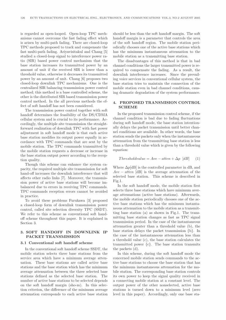
Where ∆p[dB] is the controlled parameter in dB, andAve − atten [dB] is the average attenuation of theselected base station. This scheme is described inFig.1.
In the soft handoff mode, the mobile station firstselects three base stations which have minimum aver-age attenuations (active base stations). Afterwards,the mobile station periodically chooses one of the ac-tive base stations which has the minimum instanta-neous attenuation to the mobile station as a transmit-ting base station (a) as shown in Fig.1. The trans-mitting base station changes as fast as TPC signaltransmission period. In the case of the instantaneousattenuation greater than a threshold value (b), thebase station delays the packet transmission {b}. Inthe case of the instantaneous attenuation less thana threshold value (c), the base station calculates thetransmitted power {c}. The base station transmitsthe packets (d).
In this scheme, during the soft handoff mode theconcerned mobile station sends commands to the ac-tive base stations to choose the base station that hasthe minimum instantaneous attenuation for the mo-bile station. The corresponding base station controlsits own power to keep the signal quality received ina connecting mobile station at a constant level. Theoutput power of the other nonselected, active basestations is turned down to a minimum level (zerolevel in this paper). Accordingly, only one base sta-
Downlink Packet Transmission Control in Soft Handoff Status on CDMA Wireless IP Networks 127
(a)(b)
(c)
{c}
{b}
Mobile station (Ms)Selected base station (Bs)
Active base stations
(d)
Fig.1: Proposed soft handoff scheme
tion among the active base stations provides adequatepower to the connected mobile station.
By applying this proposed transmission controlscheme the system throughput could be efficientlyimproved. The tolerable delay time would not af-fect IP packets transmission when these packets arenot supporting real time applications. Although thisscheme is intended to support applications, which donot have stringent delay requirements, it can be usedfor real time applications, because the proposed con-trol scheme is limited to during soft handoff mode.The computer simulation results which compare ourproposed scheme with the conventional soft handoffscheme are presented in section 6.
5. SYSTEM MODEL
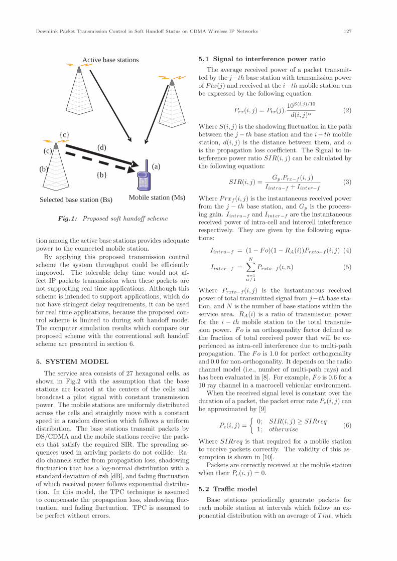
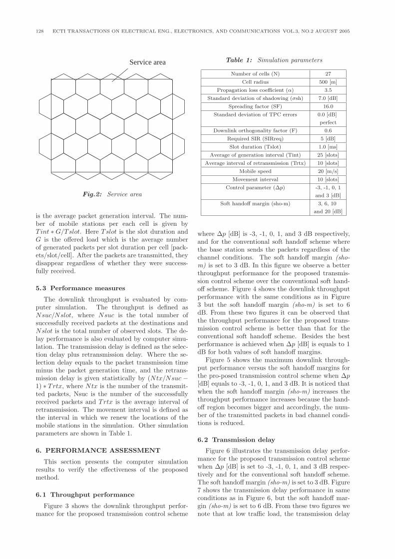
The service area consists of 27 hexagonal cells, asshown in Fig.2 with the assumption that the basestations are located at the centers of the cells andbroadcast a pilot signal with constant transmissionpower. The mobile stations are uniformly distributedacross the cells and straightly move with a constantspeed in a random direction which follows a uniformdistribution. The base stations transmit packets byDS/CDMA and the mobile stations receive the pack-ets that satisfy the required SIR. The spreading se-quences used in arriving packets do not collide. Ra-dio channels suffer from propagation loss, shadowingfluctuation that has a log-normal distribution with astandard deviation of σsh [dB], and fading fluctuationof which received power follows exponential distribu-tion. In this model, the TPC technique is assumedto compensate the propagation loss, shadowing fluc-tuation, and fading fluctuation. TPC is assumed tobe perfect without errors.
5.1 Signal to interference power ratio
The average received power of a packet transmit-ted by the j−th base station with transmission powerof Ptx(j) and received at the i−th mobile station canbe expressed by the following equation:
Prx(i, j) = Ptx(j).10S(i,j)/10
d(i, j)α(2)
Where S(i, j) is the shadowing fluctuation in the pathbetween the j − th base station and the i− th mobilestation, d(i, j) is the distance between them, and αis the propagation loss coefficient. The Signal to in-terference power ratio SIR(i, j) can be calculated bythe following equation:
SIR(i, j) =Gp.Prx−f (i, j)
Iintra−f + Iinter−f(3)
Where Prxf (i, j) is the instantaneous received powerfrom the j − th base station, and Gp is the process-ing gain. Iintra−f and Iinter−f are the instantaneousreceived power of intra-cell and intercell interferencerespectively. They are given by the following equa-tions:
Iintra−f = (1 − Fo)(1 − RA(i))Prxto−f (i, j) (4)
Iinter−f =N∑
n=1n �=1
Prxto−f (i, n) (5)
Where Prxto−f (i, j) is the instantaneous receivedpower of total transmitted signal from j−th base sta-tion, and N is the number of base stations within theservice area. RA(i) is a ratio of transmission powerfor the i − th mobile station to the total transmis-sion power. Fo is an orthogonality factor defined asthe fraction of total received power that will be ex-perienced as intra-cell interference due to multi-pathpropagation. The Fo is 1.0 for perfect orthogonalityand 0.0 for non-orthogonality. It depends on the radiochannel model (i.e., number of multi-path rays) andhas been evaluated in [8]. For example, Fo is 0.6 for a10 ray channel in a macrocell vehicular environment.
When the received signal level is constant over theduration of a packet, the packet error rate Pe(i, j) canbe approximated by [9]
Pe(i, j) ={
0; SIR(i, j) ≥ SIRreq1; otherwise
(6)
Where SIRreq is that required for a mobile stationto receive packets correctly. The validity of this as-sumption is shown in [10].
Packets are correctly received at the mobile stationwhen their Pe(i, j) = 0.
5.2 Traffic model
Base stations periodically generate packets foreach mobile station at intervals which follow an ex-ponential distribution with an average of Tint, which
128 ECTI TRANSACTIONS ON ELECTRICAL ENG., ELECTRONICS, AND COMMUNICATIONS VOL.3, NO.2 AUGUST 2005
Service area
Fig.2: Service area
is the average packet generation interval. The num-ber of mobile stations per each cell is given byTint ∗ G/Tslot. Here Tslot is the slot duration andG is the offered load which is the average numberof generated packets per slot duration per cell [pack-ets/slot/cell]. After the packets are transmitted, theydisappear regardless of whether they were success-fully received.
5.3 Performance measures
The downlink throughput is evaluated by com-puter simulation. The throughput is defined asNsuc/Nslot, where Nsuc is the total number ofsuccessfully received packets at the destinations andNslot is the total number of observed slots. The de-lay performance is also evaluated by computer simu-lation. The transmission delay is defined as the selec-tion delay plus retransmission delay. Where the se-lection delay equals to the packet transmission timeminus the packet generation time, and the retrans-mission delay is given statistically by (Ntx/Nsuc −1) ∗ Trtx, where Ntx is the number of the transmit-ted packets, Nsuc is the number of the successfullyreceived packets and Trtx is the average interval ofretransmission. The movement interval is defined asthe interval in which we renew the locations of themobile stations in the simulation. Other simulationparameters are shown in Table 1.
6. PERFORMANCE ASSESSMENT
This section presents the computer simulationresults to verify the effectiveness of the proposedmethod.
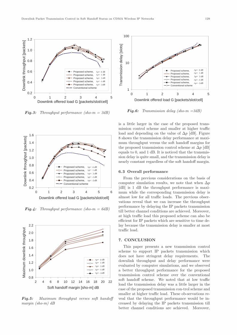
6.1 Throughput performance
Figure 3 shows the downlink throughput perfor-mance for the proposed transmission control scheme
Table 1: Simulation parameters
Number of cells (N) 27
Cell radius 500 [m]
Propagation loss coefficient (α) 3.5
Standard deviation of shadowing (σsh) 7.0 [dB]
Spreading factor (SF) 16.0
Standard deviation of TPC errors 0.0 [dB]
perfect
Downlink orthogonality factor (F) 0.6
Required SIR (SIRreq) 5 [dB]
Slot duration (Tslot) 1.0 [ms]
Average of generation interval (Tint) 25 [slots]
Average interval of retransmission (Trtx) 10 [slots]
Mobile speed 20 [m/s]
Movement interval 10 [slots]
Control parameter (∆p) -3, -1, 0, 1
and 3 [dB]
Soft handoff margin (sho-m) 3, 6, 10
and 20 [dB]
where ∆p [dB] is -3, -1, 0, 1, and 3 dB respectively,and for the conventional soft handoff scheme wherethe base station sends the packets regardless of thechannel conditions. The soft handoff margin (sho-m) is set to 3 dB. In this figure we observe a betterthroughput performance for the proposed transmis-sion control scheme over the conventional soft hand-off scheme. Figure 4 shows the downlink throughputperformance with the same conditions as in Figure3 but the soft handoff margin (sho-m) is set to 6dB. From these two figures it can be observed thatthe throughput performance for the proposed trans-mission control scheme is better than that for theconventional soft handoff scheme. Besides the bestperformance is achieved when ∆p [dB] is equals to 1dB for both values of soft handoff margins.
Figure 5 shows the maximum downlink through-put performance versus the soft handoff margins forthe pro-posed transmission control scheme when ∆p[dB] equals to -3, -1, 0, 1, and 3 dB. It is noticed thatwhen the soft handoff margin (sho-m) increases thethroughput performance increases because the hand-off region becomes bigger and accordingly, the num-ber of the transmitted packets in bad channel condi-tions is reduced.
6.2 Transmission delay
Figure 6 illustrates the transmission delay perfor-mance for the proposed transmission control schemewhen ∆p [dB] is set to -3, -1, 0, 1, and 3 dB respec-tively and for the conventional soft handoff scheme.The soft handoff margin (sho-m) is set to 3 dB. Figure7 shows the transmission delay performance in sameconditions as in Figure 6, but the soft handoff mar-gin (sho-m) is set to 6 dB. From these two figures wenote that at low traffic load, the transmission delay
Downlink Packet Transmission Control in Soft Handoff Status on CDMA Wireless IP Networks 129
Downlink offered load G [packets/slot/cell]0 1 2 3 4 5
Dow
nlin
k th
roug
hput
[pac
kets
]
0.2
0.4
0.6
0.8
1.0
1.2
Proposed scheme,Proposed scheme,Proposed scheme,Proposed scheme,Proposed scheme,Conventional scheme
0 dBp=
1 dBp=
3 dBp=
-1 dBp=
-3 dBp=
Fig.3: Throughput performance (sho-m = 3dB)
Downlink offered load G [packets/slot/cell]
0 1 2 3 4 5 6
Dow
nlin
k th
roug
hput
[pac
kets
]
0.2
0.4
0.6
0.8
1.0
1.2
1.4
1.6
Proposed scheme,Proposed scheme,Proposed scheme,Proposed scheme,Proposed scheme,Conventional scheme
0 dBp=
1 dBp=
3 dBp=
-1 dBp=
-3 dBp=
Fig.4: Throughput performance (sho-m = 6dB)
Soft handoff margin [sho-m] dB
2 4 6 8 10 12 14 16 18 20 22
Max
imum
dow
nlin
k th
roug
hput
0.8
1.0
1.2
1.4
1.6
1.8
2.0
2.2
0 dBp=
1 dBp=
3 dBp=
-1 dBp=
-3 dBp=
Fig.5: Maximum throughput verses soft handoffmargin (sho-m) dB
Downlink offered load G [packets/slot/cell]
0 1 2 3 4 5
Tra
nsm
issi
on d
elay
[slo
ts]
1
10
100
Proposed scheme,Proposed scheme,Proposed scheme,Proposed scheme,Proposed scheme,Conventional scheme
0 dBp=
1 dBp=
3 dBp=
-1 dBp=
-3 dBp=
Fig.6: Transmission delay (sho-m =3dB)
is a little larger in the case of the proposed trans-mission control scheme and smaller at higher trafficload and depending on the value of ∆p [dB]. Figure8 shows the transmission delay performance at maxi-mum throughput versus the soft handoff margins forthe proposed transmission control scheme at ∆p [dB]equals to 0, and 1 dB. It is noticed that the transmis-sion delay is quite small, and the transmission delay isnearly constant regardless of the soft handoff margin.
6.3 Overall performance
From the previous considerations on the basis ofcomputer simulation results, we note that when ∆p[dB] is 1 dB the throughput performance is maxi-mum while the corresponding transmission delay isalmost low for all traffic loads. The previous obser-vations reveal that we can increase the throughputperformance by delaying the IP packets transmissiontill better channel conditions are achieved. Moreover,at high traffic load this proposed scheme can also beefficient for IP packets which are sensitive to time de-lay because the transmission delay is smaller at mosttraffic load.
7. CONCLUSION
This paper presents a new transmission controlscheme to support IP packets transmission whichdoes not have stringent delay requirements. Thedownlink throughput and delay performance wereevaluated by computer simulations, and we observeda better throughput performance for the proposedtransmission control scheme over the conventionalsoft handoff scheme. We noted that at low trafficload the transmission delay was a little larger in thecase of the proposed transmission con-trol scheme andsmaller at higher traffic load. These ob-servations re-veal that the throughput performance would be in-creased by delaying the IP packets transmission tillbetter channel conditions are achieved. Moreover,
130 ECTI TRANSACTIONS ON ELECTRICAL ENG., ELECTRONICS, AND COMMUNICATIONS VOL.3, NO.2 AUGUST 2005
Downlink offered load G [packets/slot/cell]
0 1 2 3 4 5 6
Tra
nsm
issi
on d
elay
[slo
ts]
1
10
100
Proposed scheme,Proposed scheme,Proposed scheme,Proposed scheme,Proposed scheme,Conventional scheme
0 dBp=
1 dBp=
3 dBp=
-1 dBp=
-3dBp=
Fig.7: Transmission delay (sho-m = 6dB)
Soft handoff margin [sho-m] dB
2 4 6 8 10 12 14 16 18 20 22
Tra
nsm
issi
on d
elay
at m
axim
umth
roug
hput
[slo
ts]
10
1000 dB1 dB
p=p=
Fig.8: Transmission delay at maximum throughputversus soft handoff margin (sho-m)
this new proposed transmission control scheme couldalso be efficient for IP packets which are sensitive totime delay because the transmission delay is smallerat most of traf-fic load.
References
[1] Eunsoo Shim, Hung-yu Wei, Yusun Chang, andRichard D. Gitlin, “Low Latency Handoff forWireless IP QoS with Neighbor Casting”, Proc.Of ICC 2002, CD-ROM, May 2002.
[2] A.J.Viterbi, A. M. Viterbi, K. S. Gilhousen, andE. Zehavi. “Soft handoff extends CDMA cell cov-erage And increase reverse link capacity,” IEEEJ. Select. Areas Commun. Vol. 12, pp. 1281-1288.Oct.1994.
[3] Hiroshi Furukawa, Kojiro Hamabe, and Aki-hisa Ushirokawa. “SSDT Site Selection DiversityTransmission Power Control for CDMA ForwardLink,” IEEE J. Select. Areas Commun. VOL.18,
NO.8, pp.1546-1554. Agust 2000.[4] R.R. Gejji, “Forward link power control in CDMA
cellular systems,” IEEE Trans. Veh. Technol.,vol.41, pp.532-536, Nov. 1992.
[5] S. Ariyavisitakul and L.F Chang, “Signal andinterference statistics of a CDMA system withfeedback power control,” IEEE Trans. Commun.,VOL. COM-41, no.11, pp.1626-1634, Nov.1993.
[6] Chung-Ju Chang and Fang Ching Ren, “Cen-tralized and Distributed Downlink Power ControlMethods for a DS/CDMA Cellular Mobile Ra-dio System,” IEICE Trans. Commun., vol. E80-B,No.2, pp.366- 371, Feb. 1997.
[7] M. Soleimanipour and G.H. Freeman, “A realisticapproach to the capacity of cellular CDMA sys-tems,” in Proc. VTC96, Apr. 1996. pp.1125-1129.
[8] ETSI/SMG2, “The ETSI UMTS Terrestrial Ra-dio Access (UTRA) ITU-R RTT candidate sub-mission,” submitted to ITU-R TG 8/1 as a can-didate for IMT-2000, Oct. 1998.
[9] K. Toshimitsu, T. Yamazato, M. Katayama, andA. Ogawa, “A novel spread slotted Aloha systemwith channel load sensing protocol,” IEEE J. Sel.Areas Commun., vol.12, no.4, pp.665-672, May1994.
[10] K. Mori, T. Kobayashi, Yamazato, and A.Ogawa, “Service fairness in CDMA cellular packetsystems with site diversity reception,” IEICETrans. Commun., vol.E82-B, no.12, pp.1964-1973,Dec. 1999.
Abubaker Khumsi received his B.E.degree in Electrical and Electronic engi-neering from Alfateh University, Libya,in 1991 and received his M.E. degreein Electrical and Electronic Engineer-ing from Mie University, Japan, in 2004.From 1993 to 1998, he was a project en-gineer at Waha oil company in Libya.In 1998 he joined the higher institute ofElectroncs in Libya as an assistant lec-turer till the year 2000. He is currently
working toward the Ph.D. degree in Systems Engineering atMie University, Japan. His research interests include wirelessIP networks.
Kazuo Mori received the B.E. Degreein computer engineering from NagoyaInstitute of Technology, Japan, in 1986and received the Ph.D. degree in in-formation electronics engineering fromNagoya university, Japan in 2000. In1986, he joined the Hypermedia Re-search Center, SANYO Electric Co.,Ltd. And was engaged in research anddevelopment on Telecommunication sys-tems. From 1995 to 2000, he was a re-
search engineer at YRP Mobile Telecomunications Key Tech-nology Research Laboratories Co., Ltd., where he was engagedin research on mobile communication systems. Since 2000, hehas been an Associate Professor of the Department of Elec-trical and Electronic Engineering at Mie University, Japan.
Downlink Packet Transmission Control in Soft Handoff Status on CDMA Wireless IP Networks 131
His research interests include mobile communication systems,CDMA schemes, radio packet communications , and teletrafficevaluation. Dr. Mori received the excellent Paper Award fromIEICE, Japan in 2002.
Hideo Kobayashi received the B.E.,M.E., and Dr.E. degrees in 1975, 1977and 1989, respectively from Tohoku Uni-versity. He joined KDD in 1977, and en-gaged in research on digital fixed satel-lite and mobile satellite communicationsystems. From 1998 to 1990, he waswith INMARSAT as a Technical Staffand involved in the development of fu-ture INMARSAT systems. Since 1998he has been a Professor of Mie Univer-
sity. His current research interests include mobile communica-tions and wireless LAN systems. Dr. Kobayashi is a memberof IEEE.