Embed Size (px)
Citation preview
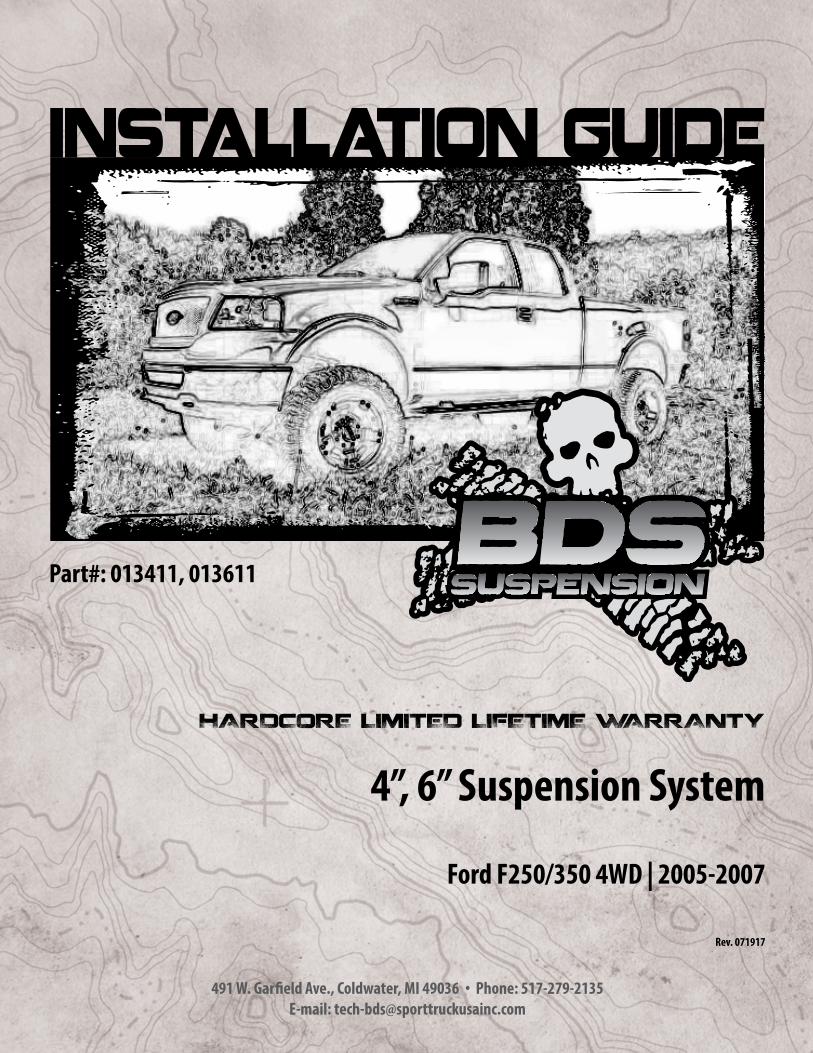
4”, 6” Suspension System
Ford F250/350 4WD | 2005-2007
Rev. 071917
Part#: 013411, 013611
491 W. Garfield Ave., Coldwater, MI 49036 . Phone: 517-279-2135E-mail: [email protected]
2 | 013411, 013611
Read And Understand All Instructions And Warnings Prior To Installation Of
System And Operation Of Vehicle.
BEFORE YOU STARTBDS Suspension Co. recommends this system be installed by a professional technician. In addition to these instructions, professional knowledge of disassembly/ reassembly procedures and post installation checks must be known.
FOR YOUR SAFETYCertain BDS Suspension products are intended to improve off-road performance. Modifying your vehicle for off-road use may result in the vehicle handling differently than a factory equipped vehicle. Extreme care must be used to prevent loss of control or vehicle rollover. Failure to drive your modified vehicle safely may result in serious injury or death. BDS Suspension Co. does not recommend the combined use of suspension lifts, body lifts, or other lifting devices. You should never operate your modified vehicle under the influence of alcohol or drugs. Always drive your modified vehicle at reduced speeds to ensure your ability to control your vehicle under all driving conditions. Always wear your seat belt.
BEFORE INSTALLATION• Special literature required: OE Service Manual for model/year
of vehicle. Refer to manual for proper disassembly/reassembly procedures of OE and related components.
• Adhere to recommendations when replacement fasteners, retainers and keepers are called out in the OE manual.
• Larger rim and tire combinations may increase leverage on suspension, steering, and related components. When selecting combinations larger than OE, consider the additional stress you could be inducing on the OE and related components.
• Post suspension system vehicles may experience drive line vibrations. Angles may require tuning, slider on shaft may require replacement, shafts may need to be lengthened or trued, and U-joints may need to be replaced.
• Secure and properly block vehicle prior to installation of BDS Suspension components. Always wear safety glasses when using power tools.
• If installation is to be performed without a hoist, BDS Suspension Co. recommends rear alterations first.
• Due to payload options and initial ride height variances, the amount of lift is a base figure. Final ride height dimensions may vary in accordance to original vehicle attitude. Always measure the attitude prior to beginning installation.
BEFORE YOU DRIVECheck all fasteners for proper torque. Check to ensure for adequate clearance between all rotating, mobile, fixed, and heated members. Verify clearance between exhaust and brake lines, fuel lines, fuel tank, floor boards and wiring harness. Check steering gear for clearance. Test and inspect brake system.
Perform steering sweep to ensure front brake hoses have adequate slack and do not contact any rotating, mobile or heated members. Inspect rear brake hoses at full extension for adequate slack. Failure to perform hose check/ replacement may result in component failure. Longer replacement hoses, if needed can be purchased from a local parts supplier.
Perform head light check and adjustment.
Re-torque all fasteners after 500 miles. Always inspect fasteners and components during routine servicing.
Your truck is about to be fitted with the best suspension system on the market today. That means you will be driving the baddest looking truck in the neighborhood, and you’ll have the warranty to ensure that it stays that way for years to come.
Thank you for choosing BDS Suspension!
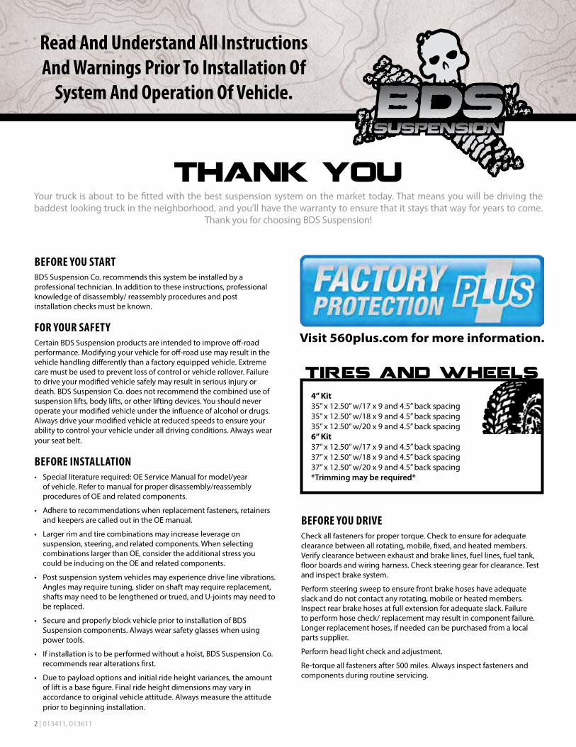
4” Kit35” x 12.50” w/17 x 9 and 4.5” back spacing35” x 12.50” w/18 x 9 and 4.5” back spacing35” x 12.50” w/20 x 9 and 4.5” back spacing6” Kit37” x 12.50” w/17 x 9 and 4.5” back spacing37” x 12.50” w/18 x 9 and 4.5” back spacing37” x 12.50” w/20 x 9 and 4.5” back spacing*Trimming may be required*
013411, 013611 | 3
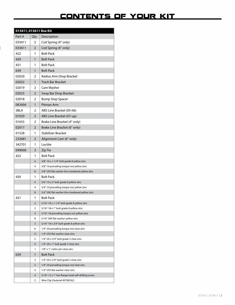
013411, 013611 Box Kit
Part # Qty Description
033411 2 Coil Spring (4" only)
033611 2 Coil Spring (6" only)
422 1 Bolt Pack
430 1 Bolt Pack
431 1 Bolt Pack
639 1 Bolt Pack
02020 2 Radius Arm Drop Bracket
02022 1 Track Bar Bracket
02019 2 Cam Washer
02025 2 Sway Bar Drop Bracket
02018 2 Bump Stop Spacer
083404 1 Pitman Arm
SBLA 2 ABS Line Bracket (05-06)
01029 2 ABS Line Bracket (07-up)
01655 2 Brake Line Bracket (4" only)
02017 2 Brake Line Bracket (6" only)
01528 1 Stabilizer Bracket
232681 2 Alignment Cam (6" only)
342701 1 Loctite
099000 3 Zip Tie
422 1 Bolt Pack4 3/8"-16 x 1-1/4" bolt grade 8 yellow zinc
4 3/8"-16 prevailing torque nut yellow zinc
8 3/8" USS flat washer thru-hardened yellow zinc
430 1 Bolt Pack4 3/4"-10 x 5" bolt grade 8 yellow zinc
4 3/4"-10 prevailing torque nut yellow zinc
8 3/4" SAE flat washer thru-hardened yellow zinc
431 1 Bolt Pack2 5/16"-18 x 1-1/4" bolt grade 8 yellow zinc
2 5/16"-18 x 1" bolt grade 8 yellow zinc
4 5/16"-18 prevailing torque nut yellow zinc
8 5/16" SAE flat washer yellow zinc
2 5/16"-18 x 3/4" bolt grade 8 yellow zinc
6 1/4"-20 prevailing torque nut clear zinc
12 1/4" USS flat washer clear zinc
2 1/4"-20 x 3/4" bolt grade 5 clear zinc
4 1/4"-20 x 1" bolt grade 5 clear zinc
1 1/8" x 1" cotter pin clear zinc
639 1 Bolt Pack2 1/4"-20 x 3/4" bolt grade 5 clear zinc
2 1/4"-20 prevailing torque nut clear zinc
4 1/4" USS flat washer clear zinc
4 5/16"-13 x 1" hex flange head self-drilling screw
2 Wire Clip (Fastenal #0708762)
4 | 013411, 013611
INSTALLATION INSTRUCTIONS1. Park the vehicle on a clean, flat surface and block the rear wheels for safety.
2. Disconnect the front track bar from the frame mount. Retain hardware.
3. Raise the front of the vehicle and support under the frame rails with jack stands.
Note: As a result of the location of the long radius arm suspension, support locations are limited. Use your best judgment while supporting the vehicle with sufficient strength stands at appropriate locations. The radius arms will need to move freely during this installation.
4. Remove the front wheels.
5. Support the front axle with a hydraulic jack.
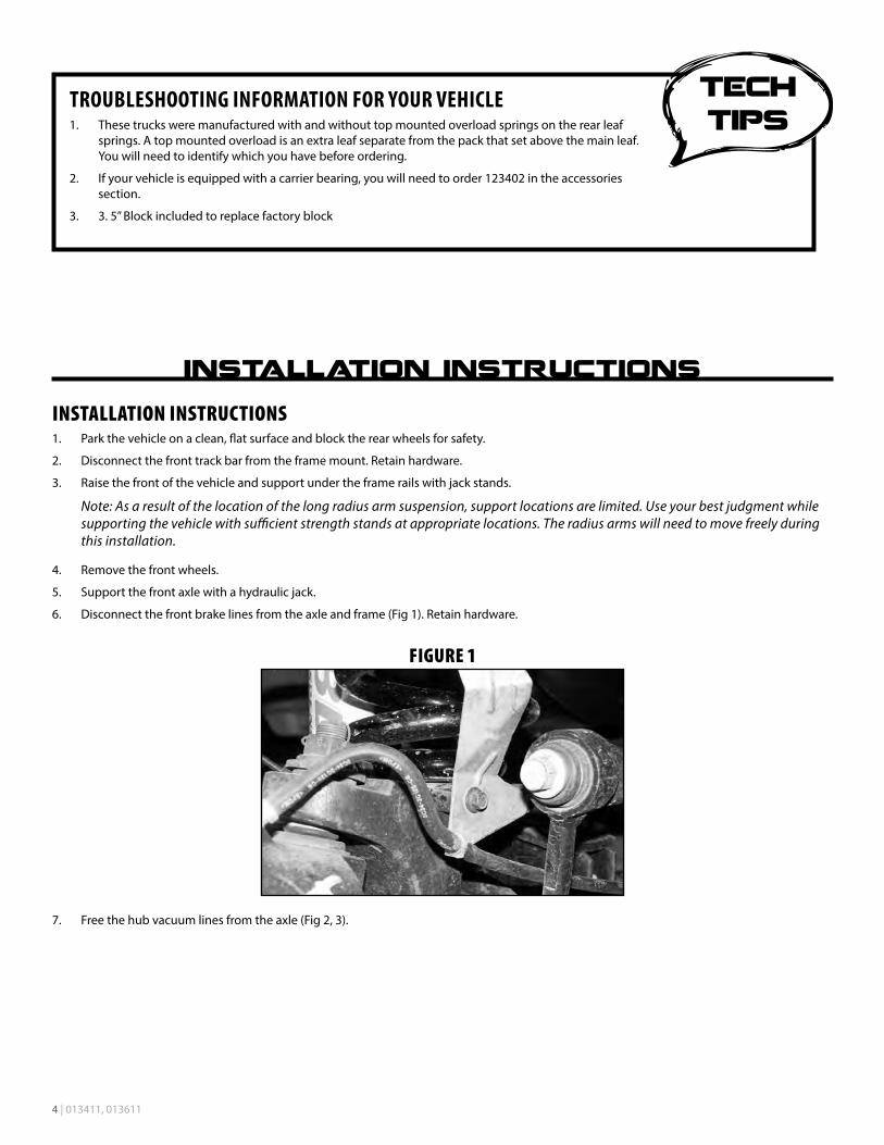
6. Disconnect the front brake lines from the axle and frame (Fig 1). Retain hardware.
FIGURE 1
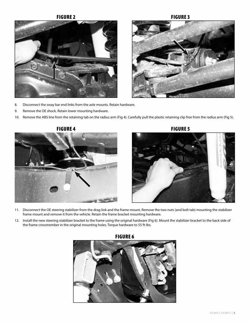
7. Free the hub vacuum lines from the axle (Fig 2, 3).
TROUBLESHOOTING INFORMATION FOR YOUR VEHICLE1. These trucks were manufactured with and without top mounted overload springs on the rear leaf
springs. A top mounted overload is an extra leaf separate from the pack that set above the main leaf. You will need to identify which you have before ordering.
2. If your vehicle is equipped with a carrier bearing, you will need to order 123402 in the accessories section.
3. 3. 5” Block included to replace factory block
013411, 013611 | 5
FIGURE 2 FIGURE 3
8. Disconnect the sway bar end links from the axle mounts. Retain hardware.
9. Remove the OE shock. Retain lower mounting hardware.
10. Remove the ABS line from the retaining tab on the radius arm (Fig 4). Carefully pull the plastic retaining clip free from the radius arm (Fig 5).
FIGURE 4 FIGURE 5
11. Disconnect the OE steering stabilizer from the drag link and the frame mount. Remove the two nuts (and bolt tab) mounting the stabilizer frame mount and remove it from the vehicle. Retain the frame bracket mounting hardware.
12. Install the new steering stabilizer bracket to the frame using the original hardware (Fig 6). Mount the stabilizer bracket to the back side of the frame crossmember in the original mounting holes. Torque hardware to 55 ft-lbs.
FIGURE 6
6 | 013411, 013611
13. Install the provided shock stud in the new stabilizer bracket up through the bracket so that the stud points down (Fig 6). Torque to 50 ft-lbs.
14. Disconnect the (5) bolts mounting the OE track bar bracket to the frame. Remove bracket and retain hardware.
15. Disconnect the drag link from the pitman arm. Retain hardware. Free the drag link from the pitman arm with a pickle fork.
16. Remove the pitman arm nut. Note the indexing of the pitman arm in relation to the steering sector shaft and remove the pitman arm from the steering box using the appropriate puller.
17. Remove all of the dri-lock compound on the threads of the OE nut and steering sector shafts. This is important to ensure that the new thread lock compound will adhere properly.
18. Apply a bead of the supplied thread lock all the way around the threads of the OE nut.
19. Install the new pitman arm (indexed the same as the OE) and fasten with the OE nut. Torque the nut to 350 ft-lbs.
20. Lower the axle until the OE coil springs are free and remove the springs from the vehicle. Retain the upper spring isolator for use with the new springs.
Note: Do not over extend the brake lines.
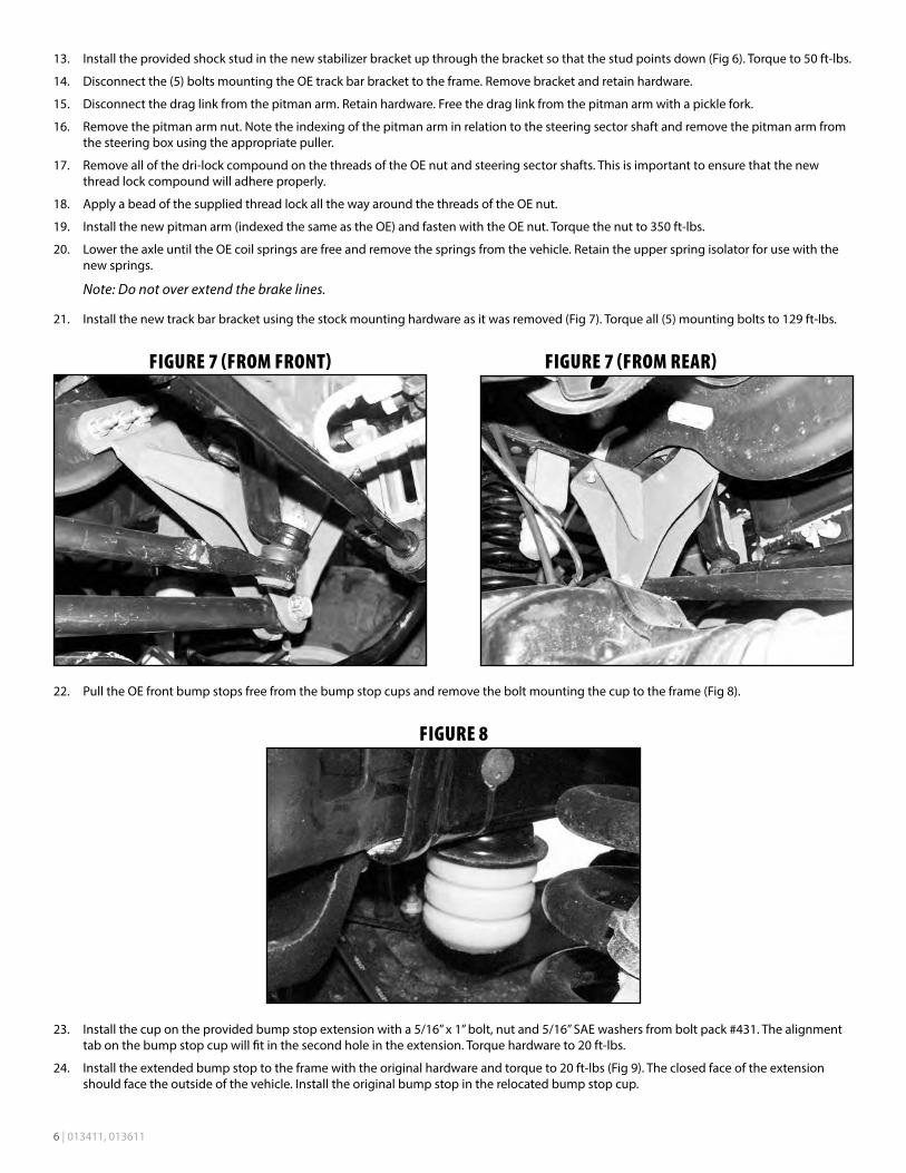
21. Install the new track bar bracket using the stock mounting hardware as it was removed (Fig 7). Torque all (5) mounting bolts to 129 ft-lbs.
FIGURE 7 (FROM FRONT) FIGURE 7 (FROM REAR)
22. Pull the OE front bump stops free from the bump stop cups and remove the bolt mounting the cup to the frame (Fig 8).
FIGURE 8
23. Install the cup on the provided bump stop extension with a 5/16” x 1” bolt, nut and 5/16” SAE washers from bolt pack #431. The alignment tab on the bump stop cup will fit in the second hole in the extension. Torque hardware to 20 ft-lbs.
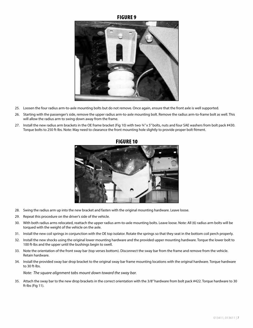
24. Install the extended bump stop to the frame with the original hardware and torque to 20 ft-lbs (Fig 9). The closed face of the extension should face the outside of the vehicle. Install the original bump stop in the relocated bump stop cup.
013411, 013611 | 7
FIGURE 9
25. Loosen the four radius arm-to-axle mounting bolts but do not remove. Once again, ensure that the front axle is well supported.
26. Starting with the passenger’s side, remove the upper radius arm-to-axle mounting bolt. Remove the radius arm-to-frame bolt as well. This will allow the radius arm to swing down away from the frame.
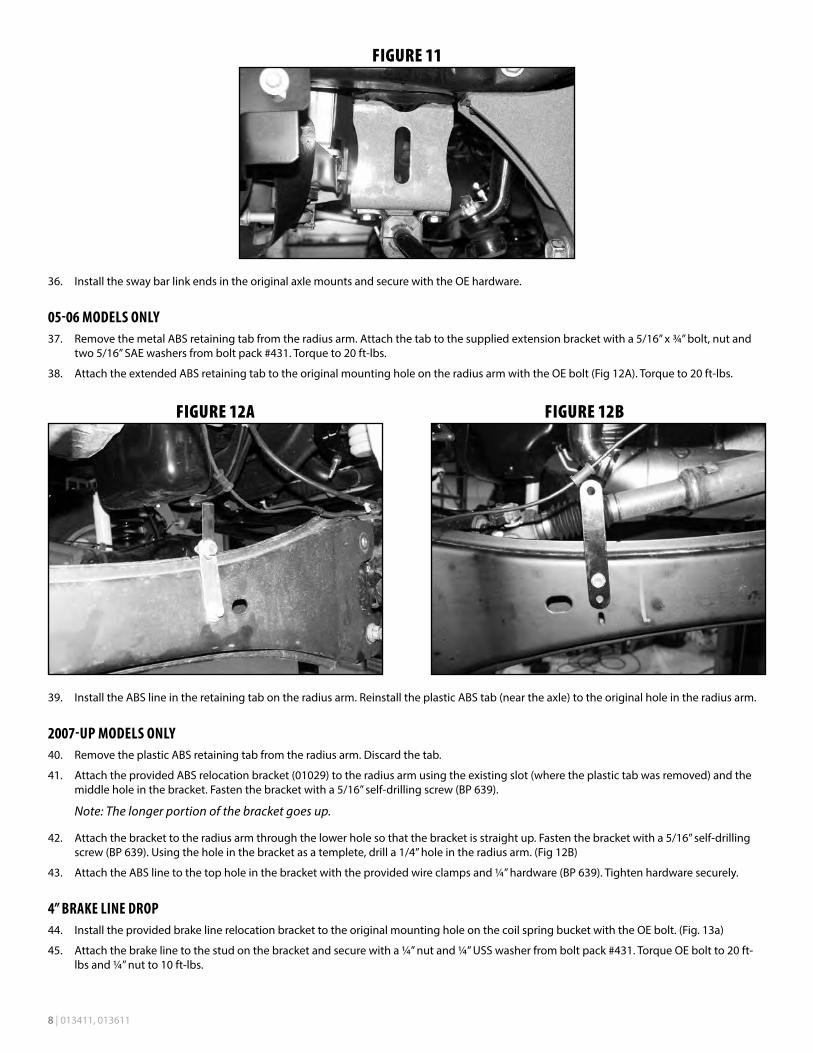
27. Install the new radius arm brackets in the OE frame bracket (Fig 10) with two ¾” x 5” bolts, nuts and four SAE washers from bolt pack #430. Torque bolts to 250 ft-lbs. Note: May need to clearance the front mounting hole slightly to provide proper bolt fitment.
FIGURE 10
28. Swing the radius arm up into the new bracket and fasten with the original mounting hardware. Leave loose.
29. Repeat this procedure on the driver’s side of the vehicle.
30. With both radius arms relocated, reattach the upper radius arm-to-axle mounting bolts. Leave loose. Note: All (6) radius arm bolts will be torqued with the weight of the vehicle on the axle.
31. Install the new coil springs in conjunction with the OE top isolator. Rotate the springs so that they seat in the bottom coil perch properly.
32. Install the new shocks using the original lower mounting hardware and the provided upper mounting hardware. Torque the lower bolt to 100 ft-lbs and the upper until the bushings begin to swell.
33. Note the orientation of the front sway bar (top verses bottom). Disconnect the sway bar from the frame and remove from the vehicle. Retain hardware.
34. Install the provided sway bar drop bracket to the original sway bar frame mounting locations with the original hardware. Torque hardware to 30 ft-lbs.
Note: The square alignment tabs mount down toward the sway bar.
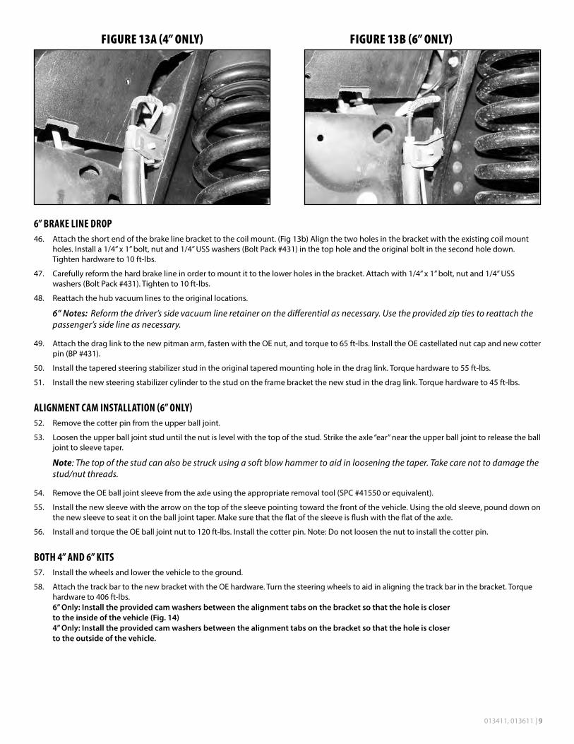
35. Attach the sway bar to the new drop brackets in the correct orientation with the 3/8” hardware from bolt pack #422. Torque hardware to 30 ft-lbs (Fig 11).
8 | 013411, 013611
FIGURE 11
36. Install the sway bar link ends in the original axle mounts and secure with the OE hardware.
05-06 MODELS ONLY37. Remove the metal ABS retaining tab from the radius arm. Attach the tab to the supplied extension bracket with a 5/16” x ¾” bolt, nut and
two 5/16” SAE washers from bolt pack #431. Torque to 20 ft-lbs.
38. Attach the extended ABS retaining tab to the original mounting hole on the radius arm with the OE bolt (Fig 12A). Torque to 20 ft-lbs.
FIGURE 12A FIGURE 12B
39. Install the ABS line in the retaining tab on the radius arm. Reinstall the plastic ABS tab (near the axle) to the original hole in the radius arm.
2007-UP MODELS ONLY40. Remove the plastic ABS retaining tab from the radius arm. Discard the tab.
41. Attach the provided ABS relocation bracket (01029) to the radius arm using the existing slot (where the plastic tab was removed) and the middle hole in the bracket. Fasten the bracket with a 5/16” self-drilling screw (BP 639).
Note: The longer portion of the bracket goes up.
42. Attach the bracket to the radius arm through the lower hole so that the bracket is straight up. Fasten the bracket with a 5/16” self-drilling screw (BP 639). Using the hole in the bracket as a templete, drill a 1/4” hole in the radius arm. (Fig 12B)
43. Attach the ABS line to the top hole in the bracket with the provided wire clamps and ¼” hardware (BP 639). Tighten hardware securely.
4” BRAKE LINE DROP44. Install the provided brake line relocation bracket to the original mounting hole on the coil spring bucket with the OE bolt. (Fig. 13a)
45. Attach the brake line to the stud on the bracket and secure with a ¼” nut and ¼” USS washer from bolt pack #431. Torque OE bolt to 20 ft-lbs and ¼” nut to 10 ft-lbs.
013411, 013611 | 9
FIGURE 13A (4” ONLY) FIGURE 13B (6” ONLY)
6” BRAKE LINE DROP46. Attach the short end of the brake line bracket to the coil mount. (Fig 13b) Align the two holes in the bracket with the existing coil mount
holes. Install a 1/4” x 1” bolt, nut and 1/4” USS washers (Bolt Pack #431) in the top hole and the original bolt in the second hole down. Tighten hardware to 10 ft-lbs.
47. Carefully reform the hard brake line in order to mount it to the lower holes in the bracket. Attach with 1/4” x 1” bolt, nut and 1/4” USS washers (Bolt Pack #431). Tighten to 10 ft-lbs.
48. Reattach the hub vacuum lines to the original locations.
6” Notes: Reform the driver’s side vacuum line retainer on the differential as necessary. Use the provided zip ties to reattach the passenger’s side line as necessary.
49. Attach the drag link to the new pitman arm, fasten with the OE nut, and torque to 65 ft-lbs. Install the OE castellated nut cap and new cotter pin (BP #431).
50. Install the tapered steering stabilizer stud in the original tapered mounting hole in the drag link. Torque hardware to 55 ft-lbs.
51. Install the new steering stabilizer cylinder to the stud on the frame bracket the new stud in the drag link. Torque hardware to 45 ft-lbs.
ALIGNMENT CAM INSTALLATION (6” ONLY)52. Remove the cotter pin from the upper ball joint.
53. Loosen the upper ball joint stud until the nut is level with the top of the stud. Strike the axle “ear” near the upper ball joint to release the ball joint to sleeve taper.
Note: The top of the stud can also be struck using a soft blow hammer to aid in loosening the taper. Take care not to damage the stud/nut threads.
54. Remove the OE ball joint sleeve from the axle using the appropriate removal tool (SPC #41550 or equivalent).
55. Install the new sleeve with the arrow on the top of the sleeve pointing toward the front of the vehicle. Using the old sleeve, pound down on the new sleeve to seat it on the ball joint taper. Make sure that the flat of the sleeve is flush with the flat of the axle.
56. Install and torque the OE ball joint nut to 120 ft-lbs. Install the cotter pin. Note: Do not loosen the nut to install the cotter pin.
BOTH 4” AND 6” KITS57. Install the wheels and lower the vehicle to the ground.
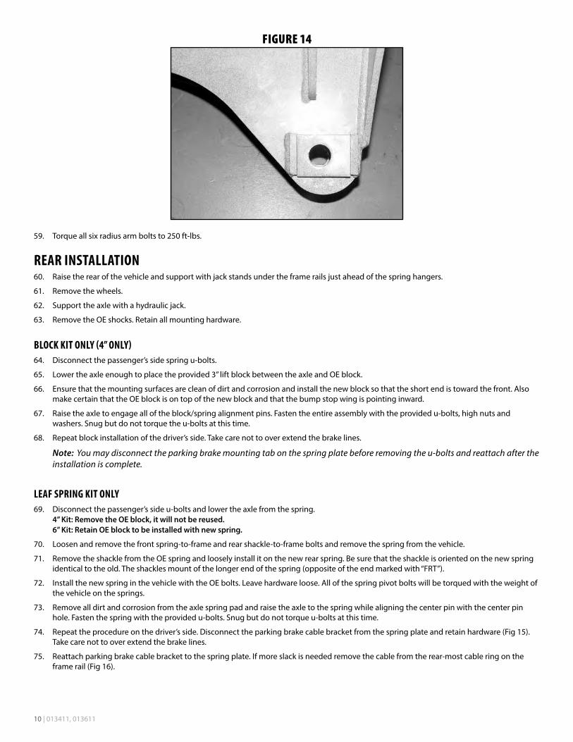
58. Attach the track bar to the new bracket with the OE hardware. Turn the steering wheels to aid in aligning the track bar in the bracket. Torque hardware to 406 ft-lbs. 6” Only: Install the provided cam washers between the alignment tabs on the bracket so that the hole is closer to the inside of the vehicle (Fig. 14) 4” Only: Install the provided cam washers between the alignment tabs on the bracket so that the hole is closer to the outside of the vehicle.
10 | 013411, 013611
FIGURE 14
59. Torque all six radius arm bolts to 250 ft-lbs.
REAR INSTALLATION60. Raise the rear of the vehicle and support with jack stands under the frame rails just ahead of the spring hangers.
61. Remove the wheels.
62. Support the axle with a hydraulic jack.
63. Remove the OE shocks. Retain all mounting hardware.
BLOCK KIT ONLY (4” ONLY)64. Disconnect the passenger’s side spring u-bolts.
65. Lower the axle enough to place the provided 3” lift block between the axle and OE block.
66. Ensure that the mounting surfaces are clean of dirt and corrosion and install the new block so that the short end is toward the front. Also make certain that the OE block is on top of the new block and that the bump stop wing is pointing inward.
67. Raise the axle to engage all of the block/spring alignment pins. Fasten the entire assembly with the provided u-bolts, high nuts and washers. Snug but do not torque the u-bolts at this time.
68. Repeat block installation of the driver’s side. Take care not to over extend the brake lines.
Note: You may disconnect the parking brake mounting tab on the spring plate before removing the u-bolts and reattach after the installation is complete.
LEAF SPRING KIT ONLY69. Disconnect the passenger’s side u-bolts and lower the axle from the spring.
4” Kit: Remove the OE block, it will not be reused. 6” Kit: Retain OE block to be installed with new spring.
70. Loosen and remove the front spring-to-frame and rear shackle-to-frame bolts and remove the spring from the vehicle.
71. Remove the shackle from the OE spring and loosely install it on the new rear spring. Be sure that the shackle is oriented on the new spring identical to the old. The shackles mount of the longer end of the spring (opposite of the end marked with “FRT”).
72. Install the new spring in the vehicle with the OE bolts. Leave hardware loose. All of the spring pivot bolts will be torqued with the weight of the vehicle on the springs.
73. Remove all dirt and corrosion from the axle spring pad and raise the axle to the spring while aligning the center pin with the center pin hole. Fasten the spring with the provided u-bolts. Snug but do not torque u-bolts at this time.
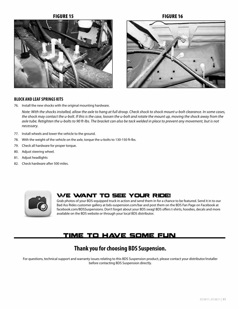
74. Repeat the procedure on the driver’s side. Disconnect the parking brake cable bracket from the spring plate and retain hardware (Fig 15). Take care not to over extend the brake lines.
75. Reattach parking brake cable bracket to the spring plate. If more slack is needed remove the cable from the rear-most cable ring on the frame rail (Fig 16).
013411, 013611 | 11
FIGURE 15 FIGURE 16
BLOCK AND LEAF SPRINGS KITS76. Install the new shocks with the original mounting hardware.
Note: With the shocks installed, allow the axle to hang at full droop. Check shock to shock mount u-bolt clearance. In some cases, the shock may contact the u-bolt. If this is the case, loosen the u-bolt and rotate the mount up, moving the shock away from the axle tube. Retighten the u-bolts to 90 ft-lbs. The bracket can also be tack welded in place to prevent any movement, but is not necessary.
77. Install wheels and lower the vehicle to the ground.
78. With the weight of the vehicle on the axle, torque the u-bolts to 130-150 ft-lbs.
79. Check all hardware for proper torque.
80. Adjust steering wheel.
81. Adjust headlights
82. Check hardware after 500 miles.
Thank you for choosing BDS Suspension.For questions, technical support and warranty issues relating to this BDS Suspension product, please contact your distributor/installer
before contacting BDS Suspension directly.